

Page 1

REVISION HISTORY
AX1
CHASSIS
MODEL
KP-FR43M31
KP-FR43M91
KP-FR43M91
NO. SUFFIX DATE SUPP / CORR DESCRIPTION
1 -01 2005/8 _ _ 1st Issue
PA RT NO. : 9-872-831-04
2 -02 2005/10 Supp-1 Loudspeaker suffix change (Pg 190)
3 -03 2005/11 Corr-1 Delete Screen (43) Contrast illustration with
no part number (Pg 156)
4 -04 2006/07 Corr-2 Part number change (Pg 157)
Page 2
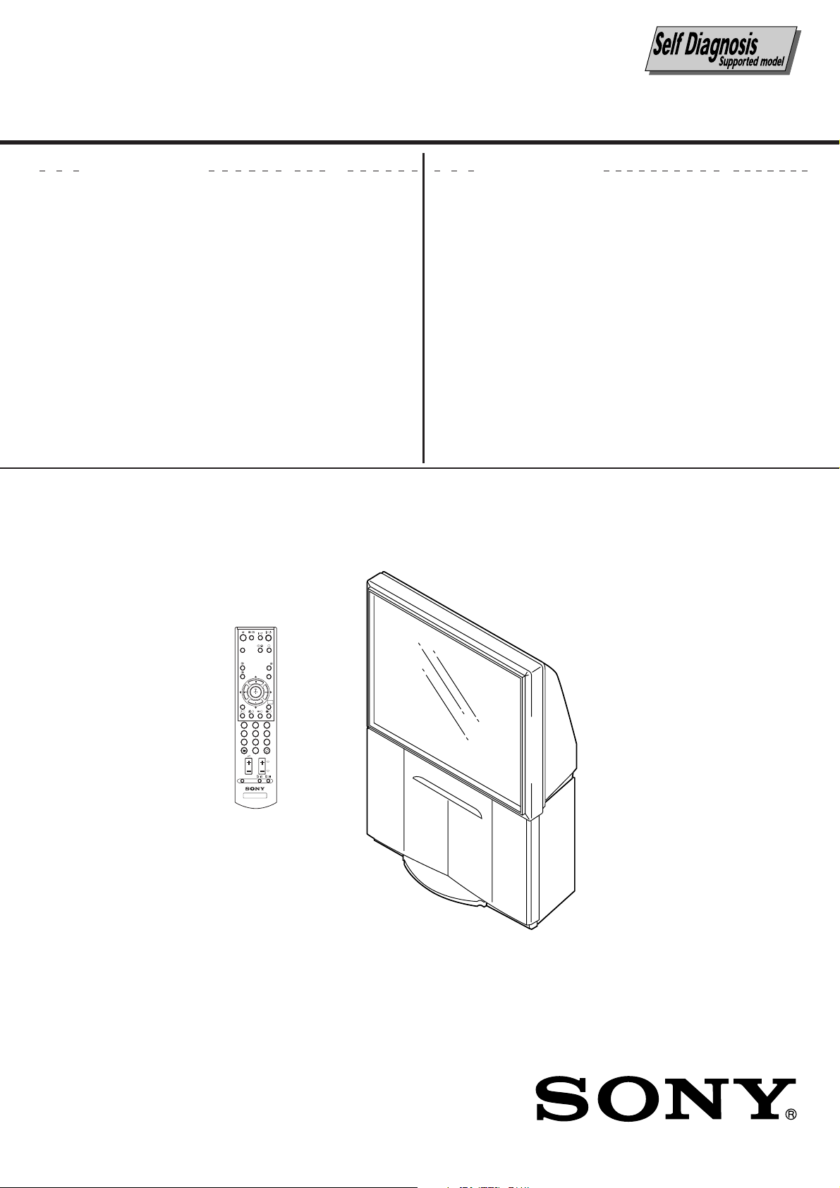
SERVICE MANUAL
AX1
CHASSIS
MODEL COMMANDER DEST. CHASSIS NO.
KP-FR43M31 RM-GA001 Oceania SCC-V43A-A
KP-FR43M91 RM-GA001 GE SCC-V42A-A
KP-FR43M91 RM-GA001 Saudi Arabia SCC-V48A-A
MODEL COMMANDER DEST. CHASSIS NO.
VIDEO
WEGA
THEATRE
A/B
PROG INDEX
WEGA
GATE
RETURN
123
4
5
6
7809
PROG
OPTION
TV
RM-GA001
RM-GA001
PROJECTION TV
Page 3

KP-FR43M31/FR43M91
RM-GA001
TABLE OF CONTENTS
Section Title Page
1. SELF DIAGNOSIS FUNCTION
1-1. Diagnostic Test Indicators ........................................... 4
1-2. Display of Standby/Timer Light Flash Count............. 5
1-3. Stopping the Standby/Timer Flash .............................. 5
1-4. Self-Diagnostic Screen Display .................................. 5
1-5. Handling of Self-Diagnostic Screen Display .............. 5
1-6. Self-Diagnostic Circuit ................................................6
2. DISASSEMBLY
2-1. Rear Cover Removal .................................................... 7
2-2. Main Bracket Removal ................................................ 7
2-3. Front Panel Assy Removal .......................................... 7
2-4. HA1, HB1, HC1 and HX Boards Removal................. 7
2-5. Mirror Cover and Beznet Block Removal ................... 8
2-6. Beznet Assy Removal .................................................. 8
2-7. Terminal Bracket Removal .......................................... 8
2-8. UG Board Removal ..................................................... 8
2-9. AD, BH, DS, MG and T Boards Removal .................. 9
2-10. A, D and G1 Boards Removal ..................................... 9
2-11. CRT and PWB Block Removal ................................... 9
2-12. High-Voltage Cable Installation and Removal .......... 10
2-13. Mechanical Assy Removal ........................................ 10
3. SET-UP ADJUSTMENTS
3-1. Screen Voltage Adjustment (Rough Alignment) ....... 11
3-2. Screen (G2) Adjustment (Fine Adjustment) ............. 11
3-3. Blue Offset Adjustment ............................................. 11
3-4. Focus Rough Adjustment .......................................... 11
3-5. Deflection Yoke Tilt Adjustment ............................... 12
3-6. 2-Pole and 4-Pole Magnet Adjustment ..................... 12
3-6-1. Adjustment of 2-Pole Magnets ................... 12
3-6-2. Green, Red, Blue Adjustment of
4-Pole Magnets ............................................ 12
3-6-3. Blue left side dot Adjustment of
2-Pole Magnets ............................................ 12
3-7. Blue Defocus Adjustment.......................................... 12
3-8. Green, Red and Blue Focus Adjustment ................... 13
3-8-1. Green, Red and Blue Lens
Focus Adjustment ........................................ 13
3-8-2. Green and Red Electrical
Focus Adjustment ........................................ 13
3-9. Final Focus Check ..................................................... 13
3-10. Adjustments with Commander ..................................13
3-10-1. How to Enter Service Mode ........................ 13
3-10-2. Method of Cancellation from
Service Mode ............................................... 14
3-10-3. How to Adjustments .................................... 14
3-10-4. How to Write the Data ................................ 14
3-10-5. Memory Write Confirmation Method ......... 14
Section Title Page
3-11. Service List ................................................................ 15
3-12. Registration Adjustment ............................................67
3-12-1. Adjustment Flow ......................................... 67
3-12-2. Setup for Adjustment .................................. 67
3-12-3. Method of Main Deflection Adjustment ..... 67
3-12-4. Operation Method for
Projector Engine (PJE) Mode ..................... 68
3-12-5. Method of Projector Engine Adjustment
(Sub Deflection Adjustment) ...................... 69
3-13. Auto Convergence Setting ......................................... 71
3-14. White Balance Adjustment ........................................ 71
3-15. Auto Convergence Error Code List ........................... 72
4. ADJUSTMENT
4-1. HV Regulation Adjustment (D Board) ...................... 73
4-2. +B Max Voltage Confirmation .................................. 73
4-3. +B OVP Confirmation ............................................... 73
5. ELECTRICAL ADJUSTMENTS
5-1. Picture Quality Adjustment ....................................... 74
5-1-1. Preparation ................................................... 74
5-1-2. NTSC Video Input (Main Picture) .............. 75
5-1-3. NTSC RF Input (Main Picture) .................. 75
5-1-4. PAL Video Input (Main Picture) ................. 76
5-1-5. PAL RF Input (Main Picture) ..................... 76
6. DIAGRAMS
6-1. Block Diagrams ......................................................... 77
6-1-1. A (1/2), D (1/2) and
HC Boards Block Diagrams................... 77
6-1-2. A (2/2) Board Block Diagram .................... 79
6-1-3. D (2/2) Board Block Diagram .................... 81
6-1-4. AD and SR Boards Block Diagrams .......... 83
6-1-5. BH Board Block Diagram ........................... 84
6-1-6. DS, G1 and T Boards Block Diagrams ....... 86
6-1-7. HA and HB1 Boards Block Diagrams ........ 88
6-1-8. MG (1/2) Board Block Diagram ................. 89
6-1-9. MG (2/2), CR, CG, CB and
VM Boards Block Diagrams .................. 91
6-1-10. UG Board Block Diagram........................... 93
6-2. Circuit Boards Location ............................................ 95
6-3. Schematic Diagrams Information.............................. 96
– 2 –
Page 4

Section Title Page
6-3-1. A Board — (Block 001) .............................. 97
6-3-2. A Board — (Block 002) .............................. 99
6-3-3. A Board — (Block 003) .............................. 99
6-3-4. AD Board Schematic Diagram ................. 101
6-3-5. BH Board — (Block 001) ......................... 104
6-3-6. BH Board — (Block 002) ......................... 106
6-3-7. BH Board — (Block 003) ......................... 108
6-3-8. CR Board Schematic Diagram .................. 109
6-3-9. CG Board Schematic Diagram.................. 110
6-3-10. CB Board Schematic Diagram .................. 111
6-3-11. D Board — (Block 001) ............................ 112
6-3-12. D Board — (Block 002) ............................ 114
6-3-13. D Board — (Block 003) ............................ 116
6-3-14. DS Board Schematic Diagram .................. 117
6-3-15. G1 Board Schematic Diagram .................. 119
6-3-16. HA1 Board Schematic Diagram ............... 121
6-3-17. HB1 Board Schematic Diagram ............... 122
6-3-18. HC1 and HX Boards
Schematic Diagrams ............................ 123
6-3-19. MG Board — (Block 001) ........................ 124
6-3-20. MG Board — (Block 002) ........................ 126
6-3-21. T Board Schematic Diagram ..................... 128
6-3-22. UG Board Schematic Diagram ................. 130
6-3-23. VM and SR Boards
Schematic Diagrams ............................ 132
6-4. Voltage Measurement and Waveforms .................... 133
6-5. Printed Wiring Boards ............................................. 138
6-6. Semiconductors ........................................................ 151
KP-FR43M31/FR43M91
RM-GA001
7. EXPLODED VIEWS
7-1. Front Panel Block .................................................... 154
7-2. Cabinet Block .......................................................... 155
7-3. Bezenet and Mirror Cover Block ............................ 156
7-4. Main Bracket and Picture Tube Block .................... 157
8. ELECTRICAL PARTS LIST........................................ 158
OPERATING INSTRUCTIONS
CAUTION
SHORT CIRCUIT THE ANODE OF THE PICTURE TUBE AND THE
ANODE CAP TO THE METAL CHASSIS, CRT SHIELD, OR
CARBON PAINTED ON THE CRT, AFTER REMOVING THE
ANODE.
SAFETY-RELATED COMPONENT WARNING!!
COMPONENTS IDENTIFIED BY SHADING AND MARK ! ON THE
SCHEMATIC DIAGRAMS, EXPLODED VIEWS AND IN THE
PARTS LIST ARE CRITICAL TO SAFE OPERATION. REPLACE
THESE COMPONENTS WITH SONY PARTS WHOSE PART
NUMBERS APPEAR AS SHOWN IN THIS MANUAL OR IN
SUPPLEMENTS PUBLISHED BY SONY.
– 3 –
Page 5

KP-FR43M31/FR43M91
RM-GA001
SECTION 1
SELF DIAGNOSTIC FUNCTION
The unit in this manual contain a self-diagnostic function. If an error occurs, the STANDBY/TIMER LED will automatically
begin to flash.
The number of times the LED flashes translates to a probable source of the problem. A defination of the STANDBY/TIMER
LED flash indicators is listed in the intruction manual for the user’s knowledge and reference. If an error symptom cannot be
reproduced, the remote commander can be used to review the failure occurrence data stored in memory to reveal past
problems and how often these problems occur.
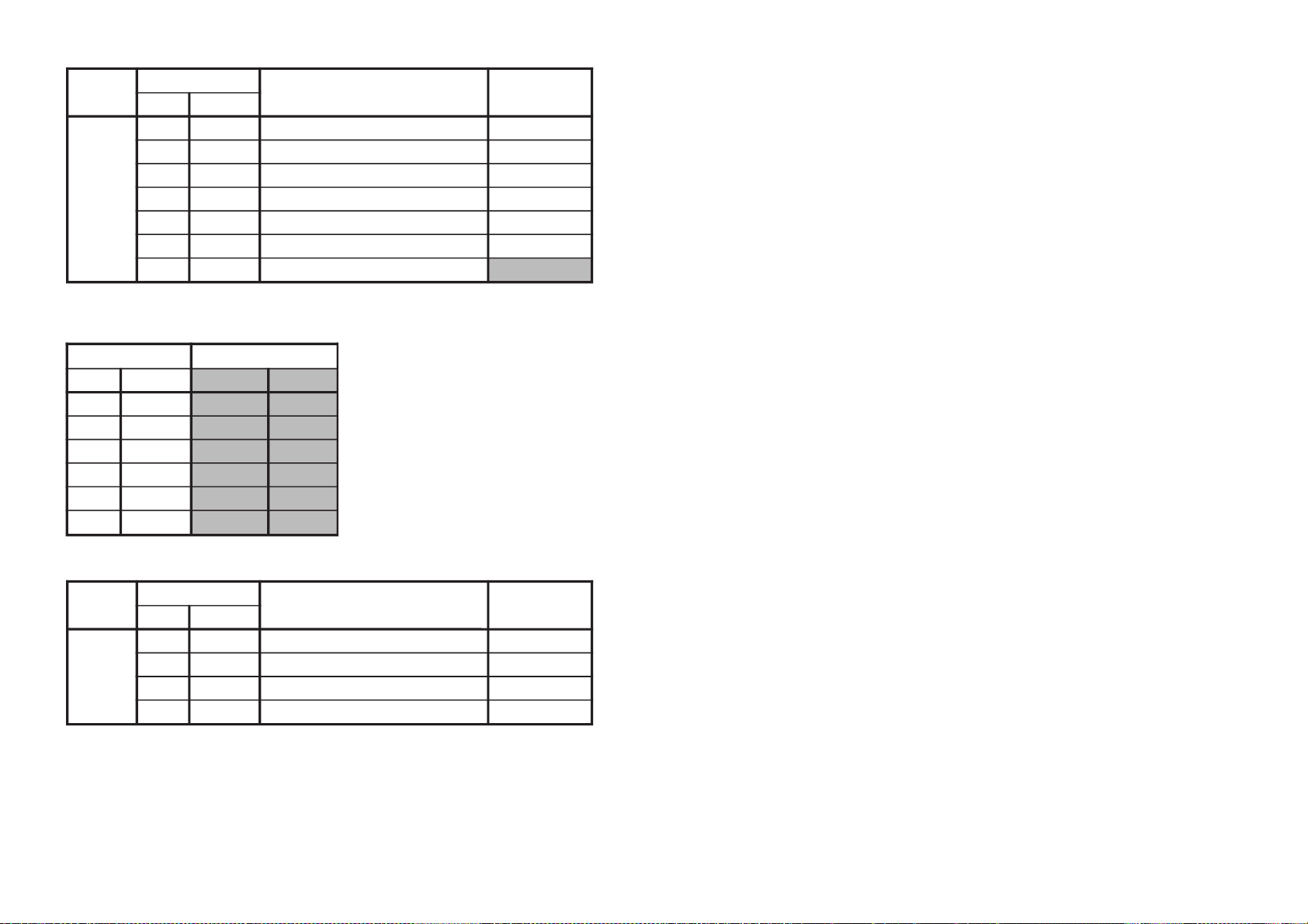
1-1. DIAGNOSTIC TEST INDICATORS
When an error occurs, the STANDBY/TIMER LED will flash a number of times to indicate the possible cause of the
problem. If there is more than one error, the LED will identify the first of the problem areas.
Result for all of the following diagnostic items are displayed on screen. If the screen displays a “0”, no error has occurred.
Diagnostic
Item
Description
•Power does not
turn on
• +B overcurrent
(OCP)
• +B overvoltage
(OVP)
•Vertical deflection
stopped
• White balance
failure
(not balanced)
•LOW B down***
• Horizontal
deflection
stopped
•Audio Protection
• Zero crossing
detector
• HV protection
No. of times
STANDBY/TIMER
LED flashes
Does not light
2 times
3 times
4 times
5 times
6 times
7 times
8 times
9 times
10 times
Self-diagnostic
display/
Diagnostic result
—
Item 2:1
or more than 1
Item 3:1
or more than 1
Item 4:1
or more than 1
Item 5:1
or more than 1
Item 6:1
or more than 1
Item 7:1
or more than 1
Item 8:1
or more than 1
Item 9:1
or more than 1
Item 10:1
or more than 1
Probable Cause Location
•Power cord is not plugged
in.
• Fuse (F6000) is burned out.
(A board)
• H.OUT (Q5001) is shorted.
• +B PWM (Q5201) is
shorted. (D board)
• IC6503 is faulty. (D board)
• 15V is not supplied.
(D board)
• IC5101 is faulty. (D board)
• Video Out
(IC9101,IC9201,IC9301)
is faulty. (CR,CG,CB board)
•CRT drive (IC0401) is faulty.
(MG board)
• G2 is impropenrly adjustd.**
• +5V line is overloaded.
(A, BM, MG boards)
• +5V line is shorted.
(A, BM, MG boards)
• IC6201 is faulty. (A board)
• Q5006 is broken. (D board)
• IC0401 is faulty. (MG board)
•+ or - 22V audio supply
is not present - Check
PS2001 & PS2000.
• D6166 or D6114 is open.
(A board)
• Q8014 or Q6013 have
shorted replace along with
R8051 on D board.
• IC8005 is damaged.
(D board)
Symptoms
•Power does not come on.
• No power is supplied to the PJ.
•AC power supply is faulty.
•Power does not turn on.
• Load on power line is shorted.
• Has entered standby mode.
• Has entered standby mode
after horizontal raster.
•Vertical deflection pulse is
stopped.
•Power line is shorted or power.
• No raster is generated.
•CRT cathode current detection
reference pulse output is small.
• No picture.
• No picture.
• No picture.
• No picture.
• No picture.
* If a +B overcurrent is detected, stoppage of the vertical detection is detected simultaneously. The symptom that is
diagnosed first by the microcontroller is displayed on the screen.
** Refer to screen (G2) adjustment (fine adjustment) in section 2 of this manual.
*** Is STANDBY/TIMER LED flashes six (6) times, unplug the unit and wait 10 seconds before performing the adjustment.
– 4 –
Page 6
KP-FR43M31/FR43M91
2 OCP : 0 7 H STOP : 0
3 OVP : 0 8 A PRT : 1
4V STOP : 0 9 Z DET : 0
5 AKB : 0 10 HV PRT : 0
6 LOW-B : 0 101 WDT : 0
Number 1
means a fault was detected one time only.
Number 0
means that no fault detected.
SELF DIAGNOSTIC
RM-GA001
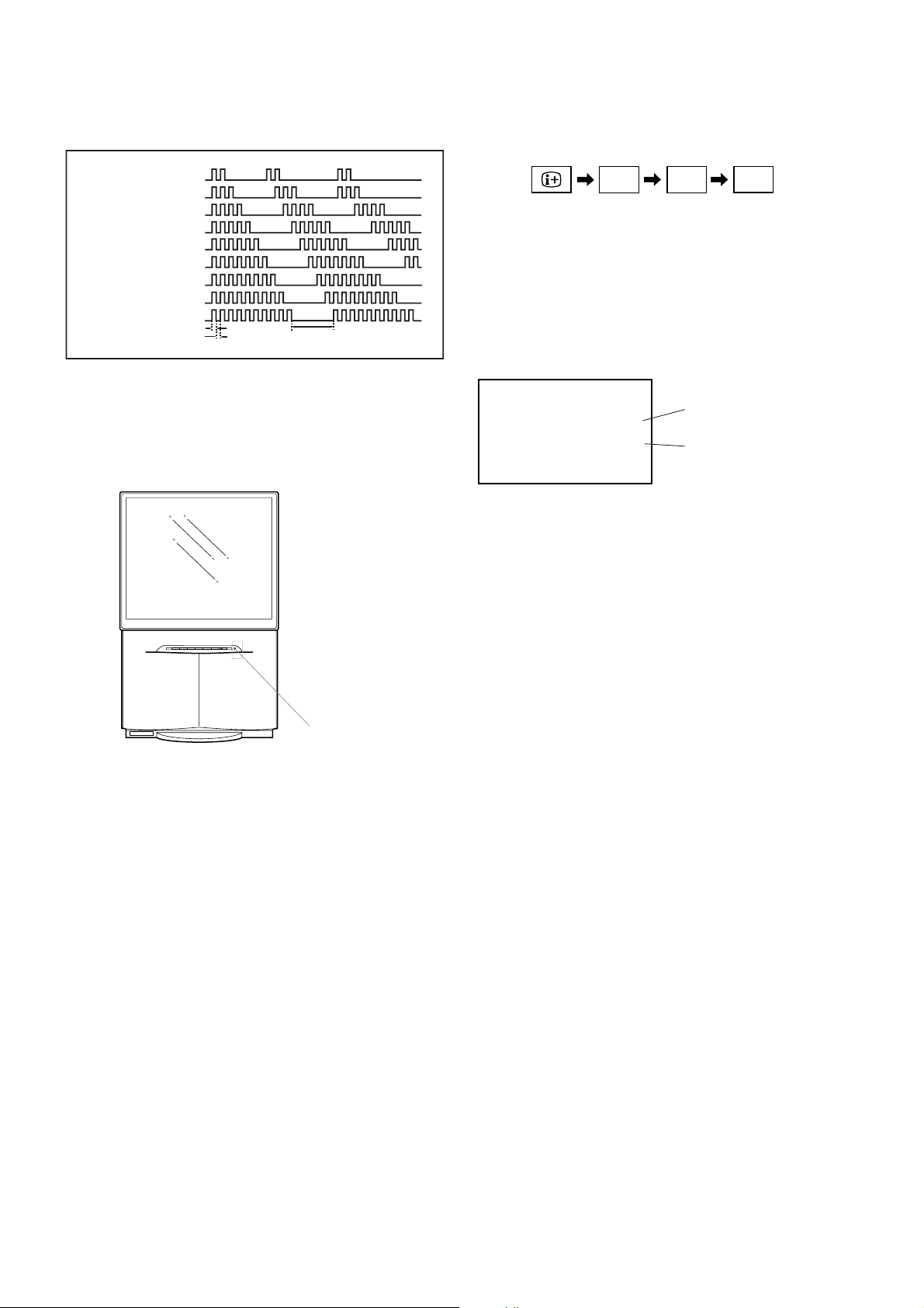
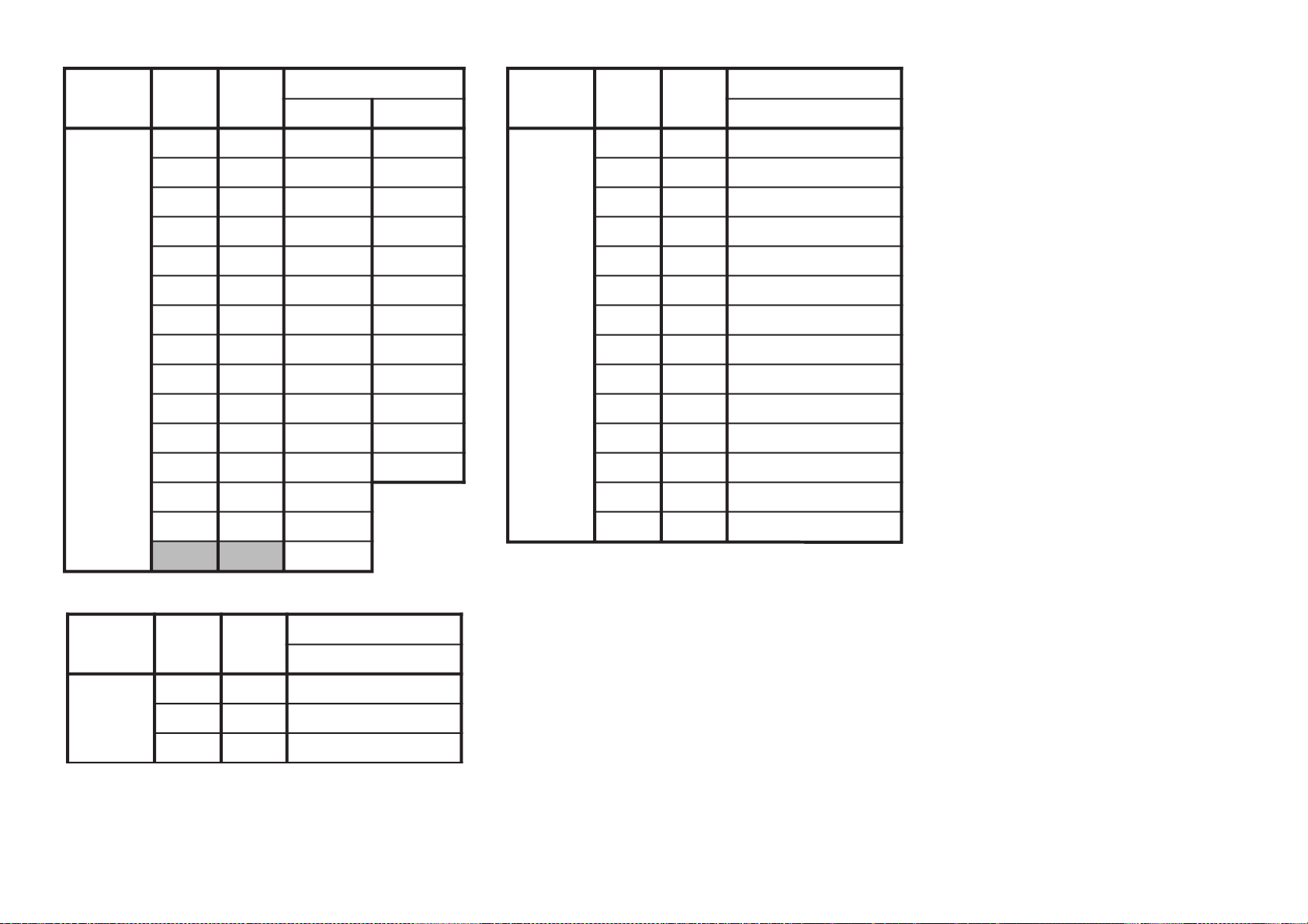
1-2. DISPLAY OF STANDBY/TIMER LIGHT FLASH
COUNT
Diagnostic items Flash count
+B Overcurrent 2 tims
Low +B Overvoltage 3 tims
Vert deflection stopped 4 tims
White balance failure 5 tims
Low +B OVP/OCP 6 tims
Horiz. deflection stopped 7 tims
Audio protection 8 tims
Zero crossing detector 9 tims
HV protection 10 tims
* One flash counts is not used for silf-diagnostic.
LED ON 0.3 sec.
LED OFF 0.3 sec.
LED OFF 3 sec.
1-3. STOPPING THE STANDBY/TIMER FLASH
Tu rn off the power switch on the TV main unit or unplug the
power cord from the outlet to stop the STANDBY/TIMER
lamp from flashing.
Self-Diagnosis is screen display:
1-5. HANDLING OF SELF-DIAGNOSTIC SCREEN
DISPLAY
5
ON SCREEN
()
DISPLAY
2 –
*(VOLUME) (POWER)(DIGIT 5)
*: Note that this differs from entering the service mode
(volume +)
Since the diagnostic results displayed on the screen are
not automatically cleared, always check the selfdiagnostic screen.
After you have completed repairs, clear the result display
to “0”
:/1
STANDBY/TIMER
1-4. SELF-DIAGNOSTIC SCREEN DISPLAY
For errors with symptoms such as “power sometimes shuts
off” or “screen sometimes goes out” that cannot be
confirmed, it is possible to bring up past occurrences of
failure for confirmation on the screen:
[To Bring Up Screen Test]
In standby mode, press buttons on the remote commander
sequentially in rapid succession as shown below:
[Clearing the result display]
To clear the result display to “0”, press button on the remote
commander sequentially as shown below when the
diagnostic screen is being displayed.
8 button
Press
(It will indicate “CLEAR” on the screen.)
Press - button
(The “CLEAR” display change to red color.)
[Quitting Self-diagnostic screen]
To quit the entire self-diagnostic screen, turn off the power
switch on the remote commander or the main unit.
– 5 –
Page 7
KP-FR43M31/FR43M91
RM-GA001
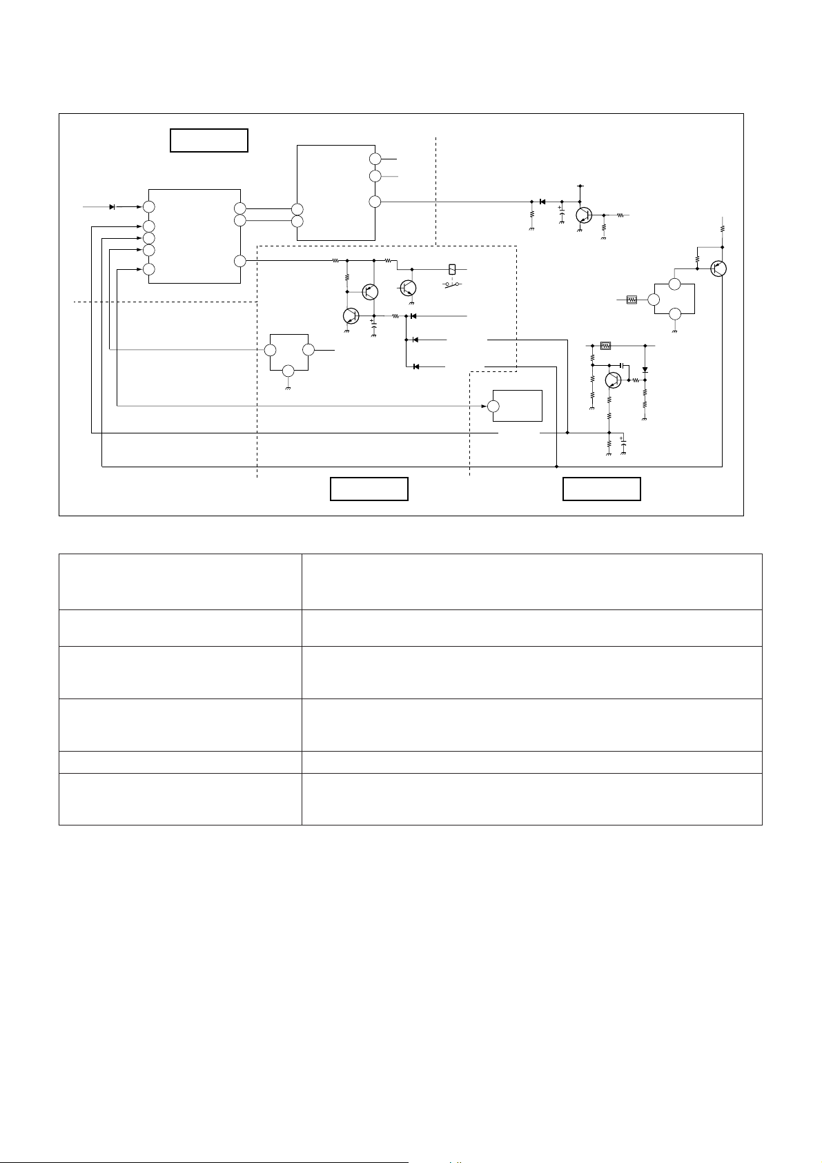
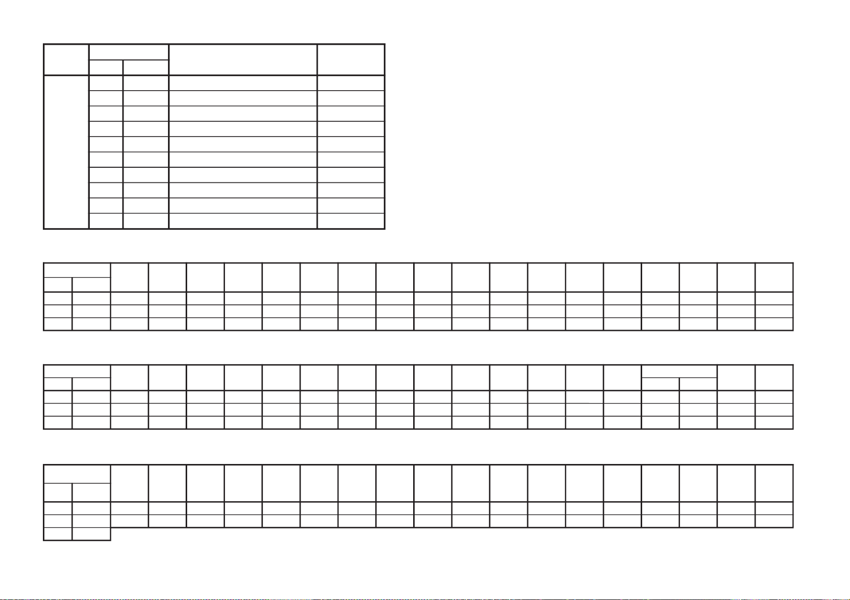
1-6. SELF-DIAGNOSTIC CIRCUIT
MG BOARD
IC0001
STBY-LED
MAIN MICRO
22
STBY-LED
5
OCP
6
OVP
87
LOW B ERR
33
HV PROT
CLKO
DATO
AC RLY
24
56
57
Q6105
CRT
VDY-
Q6102
D6803
D6122
D6121
RY6000
<+B OCP>
<+B OVP>
<P_SW(-)
<IK PROT2>
+B>
+12V
Q5202
+B>
< H PLS
IC6801
1
< +B
D6805
+15V
<
2
Q6802
3
AKB
V PROT
14
13
36
53 SCL
52 SDA
Q6108
HG PROT
IC6201
1
2
3
< +15V
IC8001
1
Q6803
<+B OCP>
A BOARD D BOARD
+B overcurrent (OCP) Occurs when excessive current flows through R6812.
The increase in voltage across Q6803 causes it to turn on which sends a high
signal to the micro.
+B overvoltage (OVP) IC6801 detects +B OVP condition and Q6802.
This sends a high signal to the micro and also shuts down the AC relay.
V-STOP Occurs when an absence of the vertical deflection pulse is detected by pin 56
of IC0404. (MG board)
Power supply will shut down when waveform interval exceeds 2 seconds.
While balance failure If the RGB levels* do not balance within 2 seconds after the power is turned
on, this error will be detected by IC0401.
TV will stay on, but there will be no picture.
Low +B OCP/OVP Occurs when set 5V is out.
Horizontal deflection stopped Occurs when either:
1) a +B overcurrent is detected (Q6803), or
2) IC0401 (MG board) is damaged.
– 6 –
Page 8
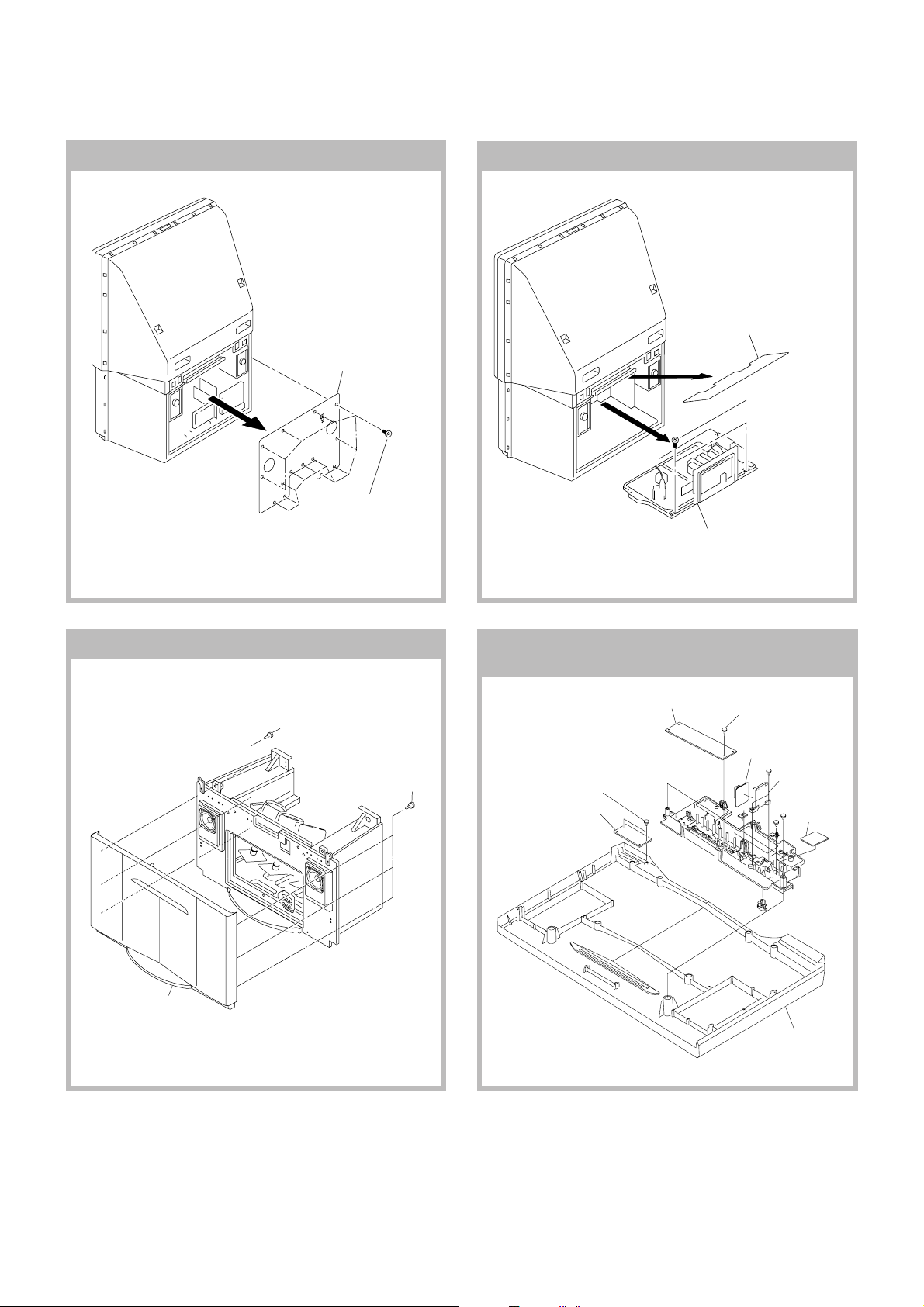
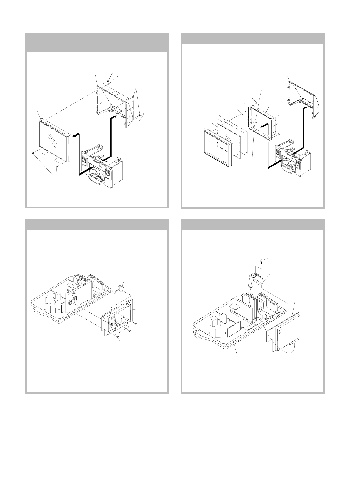
DISASSEMBLY
2 Rear board
SECTION 2
2-2. MAIN BRACKET REMOVAL2-1. REAR COVER REMOVAL
KP-FR43M31/FR43M91
RM-GA001
1 Optical shield
2 Two screws
(Tapping screw
hexagon head)
1 Fourteen screws
(Tapping screw
hexagon head)
2-3. FRONT PANEL ASSY REMOVAL
Three screws
(tapping screw
hexagon head)
Three screws
(tapping screw
hexagon head)
3 PWB block assy
2-4. HA1, HB1, HC1 AND HX
BOARDS REMOVAL
2 HA1 board
1 Two screws
(BVTP 3x12
Type2 IT-3)
3 HB1 board
Three screws
(BVTP 3x12
Type2 IT-3)
4 HC1 board
5 HC1 bracket
6 HX board
Front panel (43) assy
Front panel assy
– 7 –
Page 9
KP-FR43M31/FR43M91
RM-GA001
REMOVAL
2-6. BEZNET ASSY REMOVAL2-5. MIRROR COVER AND BEZNET BLOCK
5 Beznet block
4 Four screws
(BVTP 4x12)
3 Mirror cover
2 Four screws
2 Six screws
(BVTP 4x16)
1 Four screws
(Hexagon head)
2 Four screws
(BVTP 4x16)
6 Diffusion plate (F)
7 Diffusion plate (L)
8 Contrast screen
9 Beznet assy
2-8. UG BOARD REMOVAL2-7. TERMINAL BRACKET REMOVAL
3 Six screws
(BVTP 4x16 Type2 IT-3)
4 Screen holder (side)
5 Twelve screws
(BVTP 4x16 Type2 IT-3)
2 Holder Bracket (43L)
qf Screen holder
(TOP)
0 Screen holder
(LOW)
Mirror cover
qa Four screws
(BVTP 4x16
Type2 IT-3)
qs Screen holder
(SIDE)
qd Holder
Bracket (43R)
PWB block assy
RF splitter
4 Terminal bracket
3 Screw
(PSW 3x8)
2 Four screws
(BVTP 3x12
Type2 IT-3)
1 Two screws
(Hexagon head)
Main bracket section
1 Two screws
(PSW 3x8)
2 B bracket
3 UG board
– 8 –
Page 10
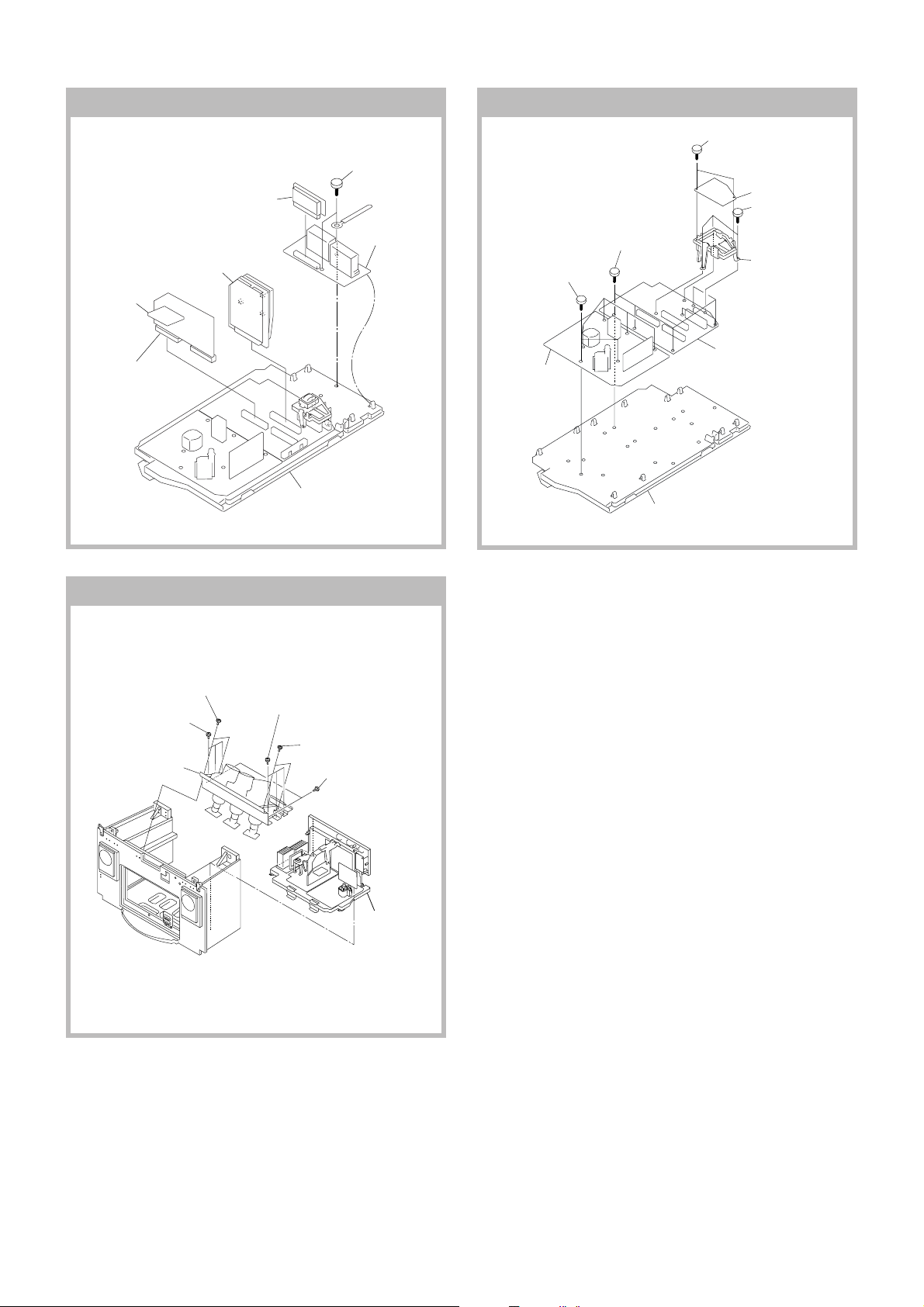
1 T board
6 MG Board
2 BH board
5 AD Board
3 Two screws
(BVTP 3x12
Type2 IT-3)
4 DS board
2-10. A, D AND G1 BOARDS REMOVAL2-9. AD, BH, DS, MG AND T BOARDS REMOVAL
7 Six screws
(BVTP 3x12)
8 D board
5 Six screws
(BVTP 3x12)
KP-FR43M31/FR43M91
RM-GA001
1 Two screws
(BVTP 3x12
Type2 IT-3)
2 G1 board
3 Three screws
(BVTP 3x12
Type2 IT-3)
4 G1 bracket
6 A board
Main bracket section
2-11. CRT AND PWB BLOCK REMOVAL
1 Two screws
(BVTP 4x16)
5 Three screws
2 Three screws
(Hexagon head)
(4x20)
3 Picture tube block assy
(Hexagon head)
(4x20)
6 Two screws
(BVTP 4x16)
4 Two screws
(Hexagon head)
(4x20)
Main bracket section
PWB block assy
– 9 –
Page 11
KP-FR43M31/FR43M91
RM-GA001
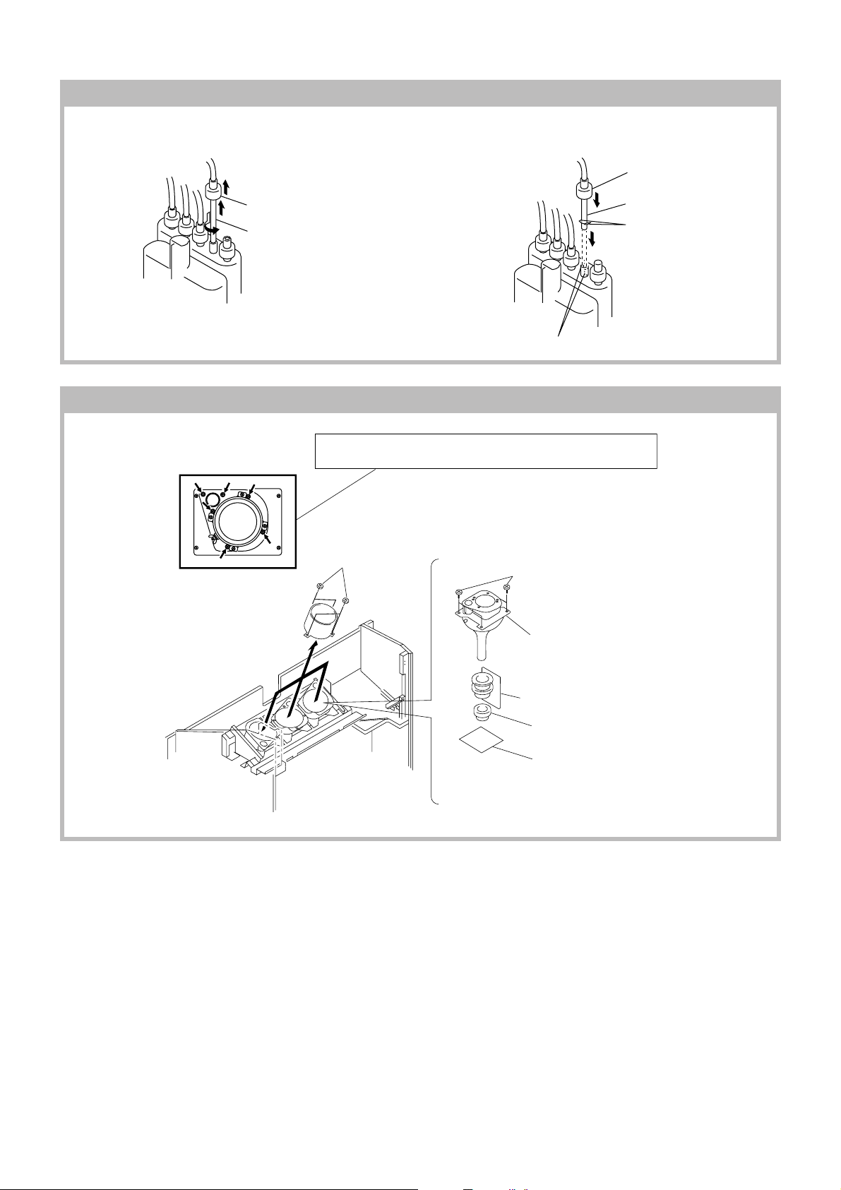
2-12. HIGH-VOLTAGE CABLE INSTALLATION AND REMOVAL
(1) Remover (2) Installation
1 Rubber cap
1 Rubber cap
2 HV cable turn 90
2-13. MECHANICAL ASSY REMOVAL
2 HV cab
Hook
Gutter
Removing the arrow-marked screw (gold color) is strictly inhibited.
If removed, it may cause liquid spill.
1 Four screws
(BVTP 4x16)
5 Four screws
(BVTP 4x16)
6 Mechaseal assy (R)
4 Deflection yoke
3 Neck assy
2 CR board
– 10 –
Page 12
SECTION 3
SET-UP ADJUSTMENTS
KP-FR43M31/FR43M91
RM-GA001
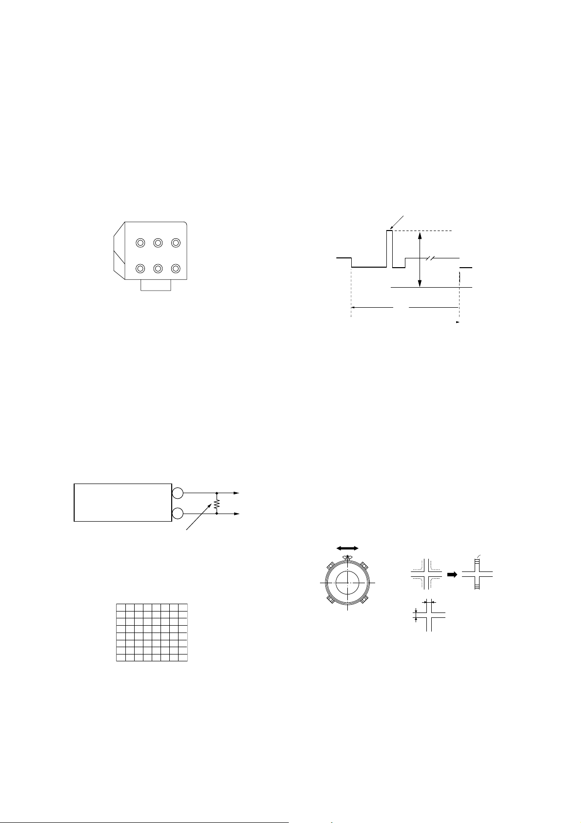
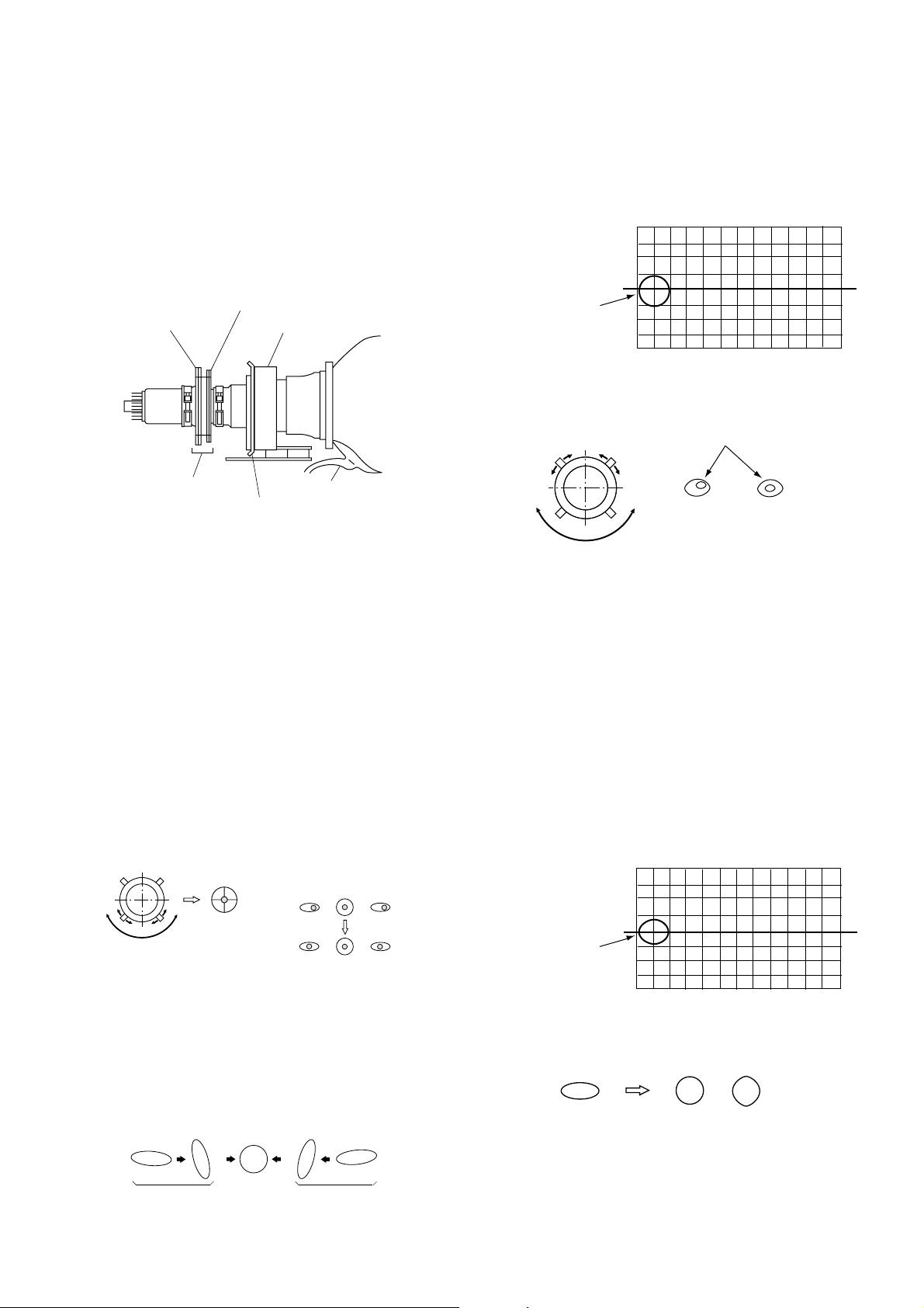
3-1. SCREEN VOLTAGE ADJUSTMENT
(ROUGH ALIGNMENT)
1. Receive the Monoscope signal.
2. Set 50% BRIGHTNESS and minimum PICTURE.
3. Turn the red VR on the focus pack all the way to the left
and then gradually turn it to the right until the point
where you can see the retrace line.
4. Next gradually turn it to the left to the position where the
retrace line disappears.
Focus Pack
FOCUS
B RG
SCREEN
BRG
Fig. 3-1
3-2. SCREEN (G2) ADJUSTMENT
(FINE ADJUSTMENT)
1. Turn on the power of the set.
2. Select VIDEO1 and make no signal input.
3. Supply DC (177.5 0.5V) from external power supply to
KR. (Fig. 3-2)
4. Turn red of G2 VR clockwise, then retrace line appear.
5. Turn G2 VR counter clockwise and set retrace line just
disappear. (Fig. 3-3)
6. Add DC voltage DC (174 0.5V) to KR.
7. Confirm if retrace can be seen.
8. Adjust green and blue at the same method.
Power
Supply
+
–
Dummy Resister
3k ohm 20W
3-3. BLUE OFFSET ADJUSTMENT
This adjustment item must be ending the G2 adjustment.
1. Input the HD (1080i/60Hz Black) signal into component
in terminal.
2. Set PICTURE 100%, others are normal,
DRC 1250/60Hz.
3. Adjust with SLN so that the blue reference pulse peak
voltage of B terminal (CN1504) enters into standard.
BLUE REFERENCE PULSE
(UG board CN1504 B5 B)
2.15
0.05V
GND (0V)
V
Item: DE F2 03 SLN
4. Write the adjustment value in the NVM area of
widezoom mode after the adjustment.
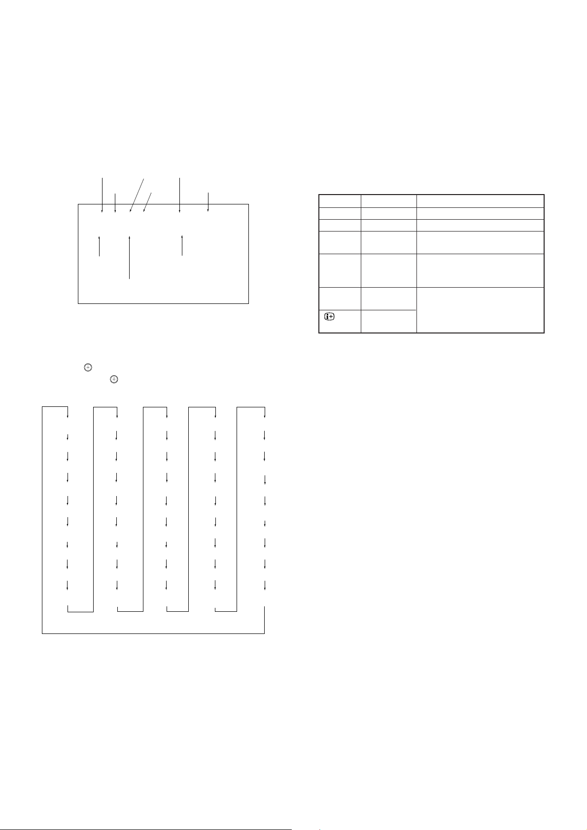
3-4. FOCUS ROUGH ADJUSTMENT
1. Connect VIDEO-1 terminal.
2. Receive video dot hatch pattern.
3. Use lens-cover to red and blue.
4. Adjust electric focus. (roughly)
5. Rotate the green lens and adjust to obtain the best lens
focus.
6. Rotate the green focus volume on the focus pack and
adjust to obtain best electrical focus.
7. If focus is not good, repeat 4 process.
8. Repeat above process for red and blue lenses and
electric focus.
9. Fix lens screw.
Scanning line visible.
Fig. 3-2
Test signal
Fig. 3-3
– 11 –
A
Minimize both A and B.
Lens
B
Fig. 3-4 Fig. 3-5
Page 13
KP-FR43M31/FR43M91
j
RM-GA001
3-5. DEFLECTION YOKE TILT ADJUSTMENT
1. Receive the Monoscope signal.
2. Place the caps on the red and blue lens so that only the
green color.
3. Loosen the deflection yoke setscrew and align the tilt of
the Deflection yoke so that the bars at the center of the
monoscope pattern are horizontal.
4. After aligning the deflection yoke, fasten it securely to
the funnel-shaped portion of the CRT.
5. The tilt of the deflection yoke for red and blue is aligned
the same as was done for green.
4-Pole Magnet
2-Pole Magnet
VM Coil Assy
Deflection Yoke
Anode Cap
Centering Magnet
Fig. 3-6
3-6-3. Blue left side dot adjustment of 2-pole Magnets
1. Turn blue focus volume of fucus pack counter-clockwise,
so that diameter of the dot becomes large, and can see
bright core position.
2. Pay attentio to left side dot of the screen. (Fig. 3-10)
3. Adjustment 2 pole magnet, so that bright core position of
dot become center position of dot. (Fig. 3-11)
Blue 2 Pole magnet
Adjustment Position
Fig. 3-10
Use the center dot Bright Core
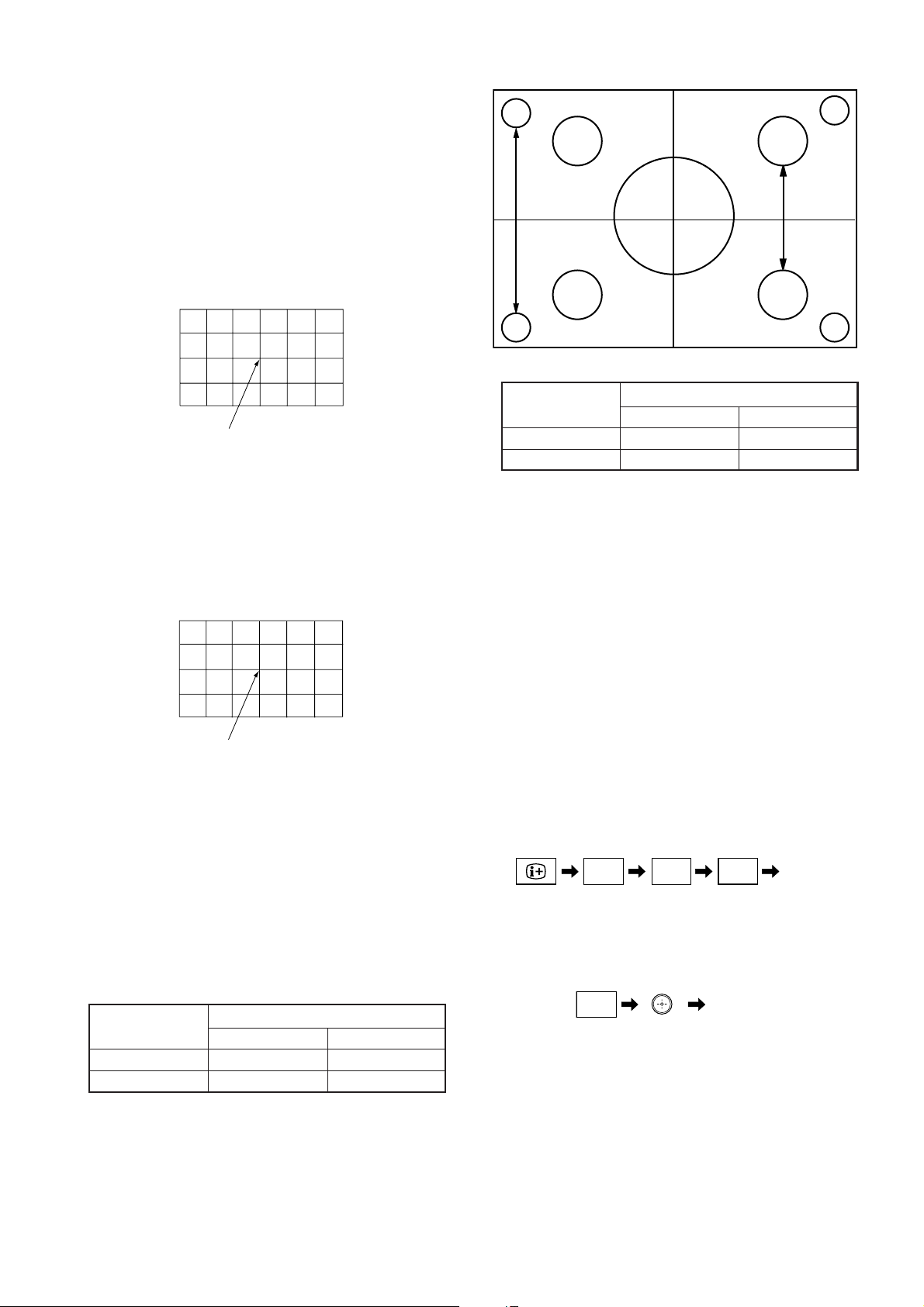
3-6. 2-POLE AND 4-POLE MAGNET ADJUSTMENT
3-6-1. Adjustment of 2-pole magnets
1. Receive the Dot signal (1080i/50Hz) from HD/DVD 1
terminal.
2. Place the caps on the red and blue lens so that only the
green color is shown.
3. Turn the green focus volume of focus pack counterclock-wise, so that diameter of the dot become large.
4. Adjust the 2-pole magnet, counter-clockwise and
clockwise center of the dot doesn’t move. (Use focus
volume)
5. Center position is changed by 2-pole magnet
adjustment. So, center magnet adjustment and 2-pole
magnet adjustment are needed tracking adjustment.
6. Repeat same adjustment method for red and blue.
Use the center dot
Left-end dot
(BLUE)
NG
OK
Fig. 3-7 Fig. 3-8
Right-end dot
(BLUE)
Fig. 3-11
3-7. BLUE DEFOCUS ADJUSTMENT
1. Receive 1080i/50Hz dot signal from HD/DVD 1 terminal.
2. Set “VIVID” and PICTURE 100%, other 50% and white
balance “COOL” (VM OFF), PIOF: 0.
3. Blue 4 pole: make round in the center of screen.
4. Confirm that center dot focus is adjusted in focus.
(Fig. 3-12a)
5. Adjust blue electrical focus to make the left side spot
nearly round by minimizing width and height. (Slight
overfocus is OK) (Fig. 3-12b)
6. Confirm that the green to blue spot size is within spec.
Blue center dot height shall be 1.2 times the g reen dot
height.
7. Return data to original condition.
Blue 2 Defocus
Adjustment Position
ust focus
3-6-2. Green, Red, Blue adjustment of 4-pole magnets
Fig. 3-12a
1. Turn Green focus volume of focus pack clockwise.
2. By using 4 pole magnets make the spot size round.
3. Repeat for red and blue.
4. Turn focus pack counter-clockwise and “Just Focus” red,
green and blue.
OK
Fig. 3-12b
NG NGOK
Fig. 3-9
– 12 –
Page 14
3-8. GREEN, RED AND BLUE FOCUS
ADJUSTMENT
3-8-1. Green, Red, Blue Lens focus adjustment
1. Input a cross hatch signal into VIDEO 1. (composite
video input)
2. Place a lens cover over red and blue lenses and project
only green.
3. Rotate the green lens and adjust to obtain the best lens
focus at the center area.
4. Fix lens screw.
5. Repeat above proces for red and blue.
Adjust Point center
Fig. 3-13
KP-FR43M31/FR43M91
RM-GA001
85% 70%
Monochromatic flare (mm)
Model Center 85% circle
53 1.0 2.5
43 1.0 2.5
3-8-1. Green and Red electrical focus adjustment
1. Input a cross-hatch signal into VIDEO 1.
2. Project only Green.
3. Rotate the green focus volume on the focus pack and
adjust to obtain the best focus at the center screen.
4. Repeat above process for red.
Adjust Point
Fig. 3-14
3-9. FINAL FOCUS CHECK
1. Receive 1080i/50Hz dot signal from HD/DVD 1 terminal.
2. Set “CUSTOM” MODE and PICTURE 100%.
3. Cap Red and blue lens.
4. Confirm that Green Resolution is within spec.
5. Receive HD (1080i) Hatch signal.
6. Confirm center and corner monochromatic flare within
spec.
7. Repeat process for Red if resolution is without spec
readjust focus.
Resolution (TV Line)
Model Center 85% circle
53 750 600
43 750 600
or NG set
1. Adjust Focus Again.
2. If NG again, rotate Green Lens 180 degree.
3. Still NG, then judge with below standard.
Center “750”
85% circle: “600” at 3 points, and “550” at 1 point
4. Replace Green, Red Lens.
We mark this Lens, try to fit this Lens with another set.
If NG again in another set, this Lens is leaved.
3-10. ADJUSTMENTS WITH COMMANDER
Service adjustment to this model can performed with the
supplied remote commander RM-GA001.
3-10-1. How to Enter Service Mode
1. Turn on the main power switch to place this set in
standby mode. (LED will light in red.)
2. Press the buttons on the commander as follows, and
enter service mode.
5
ON SCREEN
()
DISPLAY
3. After entering service mode, reset current adjustment
data. Then turn off the power switch.
2 –
(VOLUME +)(DIGIT 5)
8
(ENTER)(DIGIT 8)
4. Turn on the main power switch and enter mode again as
step 2 above.
:/1
TV
()
STANDBY
Enter the
“Reset”
Enter the
“Service mode”
– 13 –
Page 15
KP-FR43M31/FR43M91
RM-GA001
3-10-2. Method of Cancellation from Service Mode
1. Set the standby mode (Press “!/1 (TV STANDBY)”
button on the commander), then press “!/1
(TV STANDBY)” button again, hereupon it becomes TV
Mode.
3-10-3. How to Adjustments
1. Set in the service mode, the following screen will
appear.
Category Name Item Name Mode
Item No. Data
SERVICE 60 CH 6320OSD OSV
000Q 3.1M 0010 0000 20 00 00 0000
Suffix No.
Software
Version
Total Power On time
(Hours)
50 : PAL, SECAM
60 : NTSC
2. Press “1” or “4” button on the commander to select the
adjustment item.
3. Press “3” or “6” button on the commander to change
the adjustment data.
4. Move “
When move “
” up or down to select the adjustment category.
” up (category up), service mode
changes in the order as shown below.
PIC
SOU
YCTM
YCTS
MID1
MID2
DDEV
PJE*
PFOP
GUID
3-10-4. How to Write the Data
1. Set in the service mode.
2. Press “1” or “4” button on the commander, select the
adjustment item, and press “3” or “6” button to change
the data.
3. Press “% (MUTE)” button on the commander and it will
indicate “WRITE” on the screen.
4. Press “-” button on the commander to write into
memory. (The “WRITE” display will be changed to red
color while executing, and back to “SERVICE”.)
Commander Function (Except PJE mode)
Button Mode Description
% + - WRITE Writes data to NVM.
7 + - READ Reads data from NVM.
8 + - NORMAL All user control goes to the
standard.
5 + - INITIAL Service data initialization.
Not stored.
(Be sure not to use usually)
2 + - COPY Do not operate with a remote
commander.
+ - WRT5060 (The data vary with among
mode.)
Note : Before changing to other modes, press “% (MUTE)”
+ “-” buttons on the commander to write the data.
(Omission of this operation causes the data to be
returned to the data before adjustment.)
: Confirm the adjustment mode before writing data for
data values because to vary in each adjustment
mode.
: The adjustment item that there are no relations in the
adjustment is not to change data values because all
items are written in each adjustment mode.
DRC
LUMA
COLR
CLTY
MIDE
CCPM
COMB
YCTC
MCP
DEF1
DEF2
DEF3
DEF4
DEF5
MID3
VSW
CRNR
RNR
BNR
SNNR
AWID
GRN
AP
MSMO
OSDP
ASEL
VSEL
PFID
* : When it moves from PJE to other categorys,
repeat 1 or 4 button and press it.
POWR
OPM
OPB
SRV
OSD
MSP
TEXT
3-10-5. Memory Write Confirmation Method
1. After adjustment, turn off the AC main power switch off.
2. Turn the power switch ON and set in the service mode.
3. Call the adjustment items again to confirm adjustments
were made.
– 14 –
Page 16
Note
yrogetaC
metI
noitcnuFeulaVlaitnI
emaNeciveD
)sserddAevalS(
.oNemaN
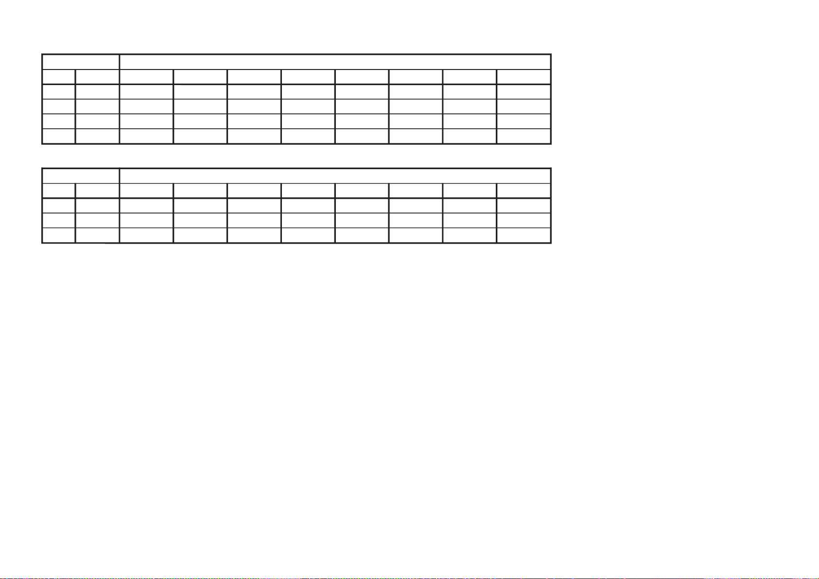
DSO0VSOnoitisoPVDSO02)H06(460F169PXC
1HSOnoitisoPHDSOD0
21WF1#puteSwodniWdleiFNEVE/DDODSO7
32WF2#puteSwodniWdleiFNEVE/DDODSO41
4FOV)tesffO(noitisoPVDSO1*
metIeulaVlaitnI
.oNemaN
TESFFOVDSO
05DH06DHSMPMOCV06PMOCV001PMOCV021PMOCV
4FOV02020202020202
metIeulaVlaitnI
.oNemaN
TESFFOVDSO
05LLUF06LLUF001LLUF021LLUF
4FOV23236161
metI eulaVlaitnI
.oNemaN
TESFFOVDSO
05MZDW06MZDW001MZDW021MZDW05MOOZ06MOOZ001MOOZ021MOOZ06XEDNI05ETIROVAF05ETIROVAF05NIWT06NIWT
4FOV020202
02
02
0202020202020202
•
•
•
• Standard data listed on the Adjustment Item Table are reference valies, therefore it may be different for each model and each
• Note for Different Data :
: The data value of each mode. Other are set up by each mode.
: Shaded items are fixed data.
: Though data value is indicated on the screen, it is not used.
Those are the standard data values written on the microprocessor. Therefore , the data values of the modes and stored respectiv
In case of a device replacement, adjustment by rewriting the data value is necessary for some items.
Version 0.60
– 15 –
3-11. SERVICE LIST
mode.
ely in the memory.
OSD: Standard Data *1
OSD: Standard Data *1
OSD: Standard Data *1
KP-FR43M31/FR43M91
RM-GA001
Page 17
yrogetaC
metI
noitcnuFeulaVlaitnI
emaNeciveD
)sserddAevalS(
.oNemaN
PSM0 TSWdlohserhToeretSG/W51)H48(D5143PSM
1TBWdlohserhTlaugniliBG/WCE
2LLWdlohserhTlaruanoMG/W5
3CAWtnuoCtnemeergAG/W1
4LDWyaleDhcraeSG/W03
5LDNyaleDhcraeSMACIN02
6LDSyaleDdaeRsutatsoeretS01
7CGAtnatsnoC/otuAhctiwSCGA1
8LERedoMtnatsnoCtaniaGCGA82
9MRCffo/nognitumreirraC0
01OCAffo/notuokcolCoiduA1
11PFmetsysM-nonrofelacserPMFB1
21MPFmetsysMrofelacserPMF23
31HFVEDHrofelacserPMF63
41MHFMdnaVEDHrofelacserPMF56
51KDHFKDdnaVEDHrofelacserPMFA1
61PGWelacserPG/WC1
71PINelacserPMACINF7
81RREdlohserhThctiwsMFotuA05
91LOVhFF70oth0070niagrekaepSduoL03
TXET0HXTnoitisoPyalpsiDlatnoziroHtxeteleTB2
1VXTnoitisoPyalpsiDlacitreVtxeteleTF3
2DHTtfihSegdEevitcacnys-HtxeteleT23
3DYTtfihSegdEevitcacnys-VtxeteleT00
4LPHnoitarugifnoCytiraloPcnys-HtxeteleT00
5LPYnoitarugifnoCytiraloPcnys-VtxeteleT00
6LPFnoitarugifnoCytiraloPdleiFtxeteleT10
7DMFedomecroFpoT/txetsaFtxeteleT30
8RBTssenthgirBBGRtxeteleTF0
9PONnoitarugifnoCelbaTnoitpOlanoitaNtxeteleTF0
01HCTnoitarugifnoCteSretcarahCdetsiwTtxeteleT3
– 16 –
KP-FR43M31/FR43M91
RM-GA001
Page 18
yrogetaC
metI
noitcnuFataDdradnatS
emaNeciveD
)sserddAevalS(
.oNemaN
CIP0CIPerutciPresU1*ERUTCIP-DEFP
1LOCroloCresU1*
2IRBthgirBresU1*
3EUHeuHresU1*
4PHSprahSresU1*
5FOIP)%57(ocE*02/)atad-02(*erutciP(tesffOerutciP1*
yrogetaC
metI
noitcnuF
ataDdradnatS
emaNeciveD
)sserddAevalS(
.oNemaN
elbaTedoMdnuoS/erutciP
cimanyDamarD/dradnatStfoS/eniF/iHlanosrePDNUOS-DEFP
UOS0SABssaBresU23232323
1ERTelberTresU23232323
PIC: Standard Data *1
metI ataDdradnatS
.oNemaN
elbaTedoMdnuoS/erutciP tesffOerutciP
cimanyD
/dradnatS
amarD
/eniF-iH
tfoS
lanosrePSM
lamroN
)3:4(
DH
/xednI/niwT
paP
rehtO
0CIP46F4A305
1LOCD4C34323
2IRB43F42323
3EUH23232323
4PHS53232323
5FOIP 55550
yrogetaC.oNemaNnoitcnuF
)1motsuCVT(etellaPCRD)2motsuCVT(etellaPCRD)3motsuCVT(etellaPCRD)1motsuCoediV(etellaPCRD)2motsuCoediV(etellaPCRD)3motsuCoediV(etellaPCRD)1motsuCpmoC(etellaPCRD)2motsuCpmoC(etellaPCRD)3motsuCpmoC(etellaPCRD
cimanyDreP/eniFiH/dtScimanyDreP/eniFiH/dtScimanyDreP/eniFiH/dtScimanyDreP/eniFiH/dtScimanyDreP/eniFiH/dtScimanyDreP/eniFiH/dtScimanyDreP/eniFiH/dtScimanyDreP/eniFiH/dtScimanyDreP/eniFiH/dtS
CRD
0RALC
ytiralCrebmunlaitnIetellaPCRDresU
000000000000000000000000000000000000
1LAER
ytilaeRrebmunlaitnIetellaPCRDresU
818181818181818181818181818181818181
– 17 –
KP-FR43M31/FR43M91
RM-GA001
Page 19
– 18 –
yrogetaC
metI
noitcnuFataDdradnatS
emaNeciveD
)sserddAevalS(
.oNemaN
DEFP0DEFPecivreSenignE-FP*enignE-fP
yrogetaC
metI
noitcnuFataDdradnatS
emaNeciveD
)sserddAevalS(
.oNemaN
DIUG
0DIUG
DIyrtnuoCtceleSediuG
)hsilgnE:3,aeroK:2,nawiT:1,hsilgnE:0(
0
yrogetaC
metI
noitcnuFeulaVlaitnI
emaNeciveD
)sserddAevalS(
.oNemaN
RWOP01YLD1yaleDnOrewoP4
12YLD2yaleDnOrewoP41
23YLD3yaleDnOrewoP4
3TEDZyaleDtceteDoreZF1
4OMTZ)sm003nimsm01*(tuoemiTtceteDoreZE1
yrogetaC.oNemaNnoitcnuFeulaVlaitnI
MAFR0IANLeulavlaitinitibANLpmAFR10
1TANLleveLdlohserhTpmAFR3C
2SANLylnolangisMACESrofleveLdlohserhTpmAFR3C
3NSNLdlohserhTleveLNSpmAFR20
4DSNLdlohserhTporDleveLNSpmAFR40
5XENLgnimiTleveLNSkcehcpmAFRA0
6RTHCedoMresUpmAFRtesotgrPotuAretfadlohserhTlennahCE1
KP-FR43M31/FR43M91
RM-GA001
Page 20
yrogetaC
metI
noitcnuFlaitnI
.oNemaN
MPO0CPAhctiwSCPA 1
1YSTmetsySVTotuAhtiwgnihcraesrednunoitceleSmetsySVT 0
2MFAhctiwSMFotuA 0
3LBDnoitcnufkcabeulBelbasiD 1
4OSSnoitceleShcraeSHCdeepS 1
5HCSnoitidnoCgnippihSrofnoitceleSHC 1
6ACSnoitidnoCgnippihSrofnoitceleSriA/elbaC 1
7
GMD
ediuGnoitarepo-uneMelbasiD
0
8
NSV
edoMoediVninoitcudeResioNelbanE
0
9BBLytisnetnIkcaBeulBrewoL 1
01P32otuA:1,FFOecroF:0edoMnwoDlluP3/2 1
11FDAHP-FD C0
21PQDAHP_PQD D0
31MILVtimiLretneC-VediW F0
411TUTatad_ecivres*]sm[01+]sm[03)xaM(1edoMemiTtiaWenuT 8
512TUTatad_ecivres*]sm[01+]sm[03)xaM(2edoMemiTtiaWenuT 5
613TUTatad_ecivres*]sm[01+]sm[03)xaM(3edoMemiTtiaWenuT 5
71WTUTesnestniop6emiTtiaWenuT 5
81RN3)teseRtseTroteseRresU(TINIRN-D3 1
91GIS.tnuoctcetedkcolforebmuntceteDlangiS-oN 1*
02GISN.retnuoctcetedkcolnuforebmuntceteDlangiS-oN 1*
12WSNL)ffo:0,otuA:1(noitidnoCtseRtseT/gnippihSretsooBlangiS 1
22MPSC )eziromemton:0,eziromem:1(yromemtsalpeekrekaepSretneC 1
metIataDdradnatS
.oNemaN
tceteD-angiS
FRoediV
91GIS0 0
02GISN0 0
– 19 –
OPM: Standard Data *1
KP-FR43M31/FR43M91
RM-GA001
Page 21
– 20 –
yrogetaC
metI
noitcnuFataDdradnatS
emaNeciveD
)sserddAevalS(
.oNemaN
BPO0 0PO0stiBlanoitpO06stiB-noitpO
11PO1stiBlanoitpO57
22PO2stiBlanoitpO3
33PO3stiBlanoitpO8
44PO4stiBlanoitpO31
yrogetaC
metI
noitcnuFataDdradnatS
emaNeciveD
)sserddAevalS(
.oNemaN
VRS0MOCdnammoCecivreS*
KP-FR43M31/FR43M91
RM-GA001
Page 22

KP-FR43M31/FR43M91
OPTION NOTE
COM Comb Operation Selection 00 = automatic operation (depends on color system status),
01 = no comb operation,
02 = forced 2D-comb operation,
03 = forced 3D-comb operation
TSY TV System Selection for Auto TV system 00 = B/G, 01 = 1, 10 = D/K, 11 = M
SSO Speed CH search Selection 00 = normal, 01 = 4 times, 10 = 6 times, 11 = 8 times
Category Item Bit 7 Bit 6 Bit 5 Bit 4 Bit 3 Bit 2 Bit 1 Bit 0
OP0 Reserved Reserved Auto TV Main-Tuner NICAM HDEV Korea Stereo US Stereo
System Stereo
OP1 Reserved Secam Center Video HD/DVD input AVIN
Speaker NTSC3.58
OP2 Msys miss Band Edge Reserved Language Language Language Language Language
Korea Taiwanese Thai Arabic S-Chinese
OP3 Reserved IK Blanking MS Blanking DRC palette DRC 3 Memory Multi Picture
Mode Stick
OP4 Reserved Power Wide/ Wide Front Key Eco Standy Zero Cross CPJ5
Narrow
RM-GA001
Auto TV System 0: TV System Fixed 1: TV System Auto Detect (Stereo Decoder)
Main-Tuner Stereo 0: Monaural 1: Stereo
NICAM 0: not available 1: available
HDEV (High Deviation Switch) 0: Auto Stereo Only 1: Auto Stereo/Fixed Monaural Select
Korean stereo 0: not available 1: available
US stereo 0: not available 1: available
SECAM 0: not available 1: available
Center Speaker 0: not available 1: available
Video NTSC3.58 0: Video 1-4 Multi Col Sys 1: Video 1-4 col Sys NTSC3.58 fixed
HD/DVD input 0: No HD/DVD input 1: HD/DVD1
2: HD/DVD 1,2,3 3: HD/DVD 1,2,3
AVIN 0: No Video 1: Video 1
2: Video 1,2,3 3: Video 1,2,3,4
Msys miss (miss detect c/m) 0: not available 1: available
Band Edge (c/m) 0: not available 1: available
Language Korea 0: not available 1: available
Language Taiwanese 0: not available 1: available
Language Thai 0: not available 1: available
Language Arabic 0: not available 1: available
Language S-Chinese 0: not available 1: available
IK Blanking (Test Bit) 0: Not used 1: Used
Memory Stick Off Blanking 0: Normal 1: long blanking
DRC palette (DRC-MF_V1) 0: not available 1: available
DRC 3 Mode 0: 2 Mode (DRC 1250/Prog) 1: 3 Mode (DRC 1250/DRC100/Prog)
Memory Stick 0: not available 1: available
Multi-Pic 0: Single 1: Quick-PAP
2: TWIN, INDEX 3: Quick-PAP & TWIN, INDEX
Power Wide/Narrow (for CTV) 0: Narrow CTV/CPJ 1: Wide CTV
Wide 0: 4:3 Model 1: 16:9 Model
Front Key 0: Front 7 key 1: Front 8 key (CPJ)
2: Front 12 key 3: Reserved (Front 12 key)
Eco-Standy 0: Standby not sleep 1: Standby sleep available
Zero Cross 0: NG Power On 1: NG Power Off
CPJ 0: TV 1: CPJs
– 21 –
Page 23
yrogetaC
metI
noitcnuFataDdradnatS
.oNemaN
1FED
0
SOPV
13
1
ZISV
03
2NILV8
3OCSV1*
4NECV13
5NIPV2*
6OCSN13
7ZPTH51
8MOOZ3*
9WSPA4*
01TPSA5*
11LRCS5*
21NLVU6*
31NLVL6*
41OSPV7*
metIataDdradnatS
.oNemaNmooZediWrehtO
3OCSV118
metIataDdradnatS
.oNemaNpmocVrehtO
5NIPV5151
metImooZ
.oNemaN
mooZediW
noitpaC
rehtO
8MOOZ10
metIataDdradnatS
.oNemaN
DH
DS
zH05zH06
9WSPA101
metI ataDdradnatS
.oNemaN
lluF lamroN/pmoCV moozediWnoitpaCmooZ
zH05zH06zH001zH021zH05zH06zH001zH021zH05zH06zH001zH021zH05zH06zH001zH021zH05zH06zH001zH021
DSBHDSDH5301DHDSDSDSDHDSDH5301DHDSDSDSDSDSDSDSDSDSDSDSDSDSDS
01TPSA 3333 3 333333 7133222222223434343434343434
11LRCS1313131313131313131313131313131313131313131313131313
metIataDdradnatS
.oNemaNmooZediWnoitpaCrehtO
21NLVU400
31NLVL4010
metIataDdradnatS
.oNemaNzH05zH06zH001zH021
41OSPV7777
PF Version 0.20I
– 22 –
KP-FR43M31/FR43M91
DEF1: Standard Data *1
RM-GA001
DEF1: Standard Data *2
DEF1: Standard Data *3
DEF1: Standard Data *6
DEF1: Standard Data *7
DEF1: Standard Data *4
DEF1: Standard Data *5
Page 24
metIataDdradnatS
.oNemaNzH05zH06zH001zH021
81OHPP7777
metIataDdradnatS
.oNemaN
zH06zH001zH021
ediW
mooZ
rehtO
ediW
mooZ
rehtO
ediW
mooZ
rehtO
91ONIP000000
01OPCU000000
12OPCL000000
metImooZ
.oNemaNmooZediWrehtO
32SHIH22
42LSIH22
52PMIH77
62NPIH11
yrogetaC
metI
noitcnuFataDdradnatS
.oNemaN
2FED0TNCH13
1SOPH1*
2ZISH2*
3NILS2*
4NIPM2*
5NIP2*
6PCU2*
7PCL2*
8AHPP3*
9GNAV13
01GNAL13
11WOBV13
21WOBL13
31GCXU0
41GCXL0
51PCXU2
61PCXL2
71PPCX0
81OHPP4*
91ONIP5*
02OPCU5*
12OPCL5*
22COAV0
32SHIH6*
42LSIH6*
52PMIH6*
62NPIH6*
metIataDdradnatS
.oNemaNDHDS
1SOPH1313
metIataDdradnatS
.oNemaNmooZediWrehtO
2ZISH9404
3NILS00
4NIDM00
5NIP0413
6PCU1353
7PCL1353
metIataDdradnatS
.oNemaNnoitpaCmooZediWmooZrehtO
8AHPP0202
DEF2: Standard Data *1
DEF2: Standard Data *2
– 23 –
DEF2: Standard Data *6
DEF2: Standard Data *3
DEF2: Standard Data *4
DEF2: Standard Data *5
KP-FR43M31/FR43M91
RM-GA001
Page 25
yrogetaC
metI
noitcnuFataDdradnatS
.oNemaN
3FED0KLBH1
1KLBL1*
2KLBR1*
3KLBV2*
4KLBT3*
5KLBB3*
6MCFA3*
7PMUJ4*
8PJDV5*
9TBKA6*
metIataDdradnatS
.oNemaNDHDS
1KLBL0505
2KLBR1313
metIataDdradnatS
.oNemaNnoitpaCmooZediWmooZrehtO
3KLBV01
metI ataDdradnatS
.oNemaN
lluF lamroN/pmoCV moozediWnoitpaCmooZ
zH05zH06zH001zH021zH05zH06zH001zH021zH05zH06zH001zH021zH05zH06zH001zH021zH05zH06zH001zH021
DSDHDSDH5301DHDSDSDSDHDSDH5301DHDSDSDSDSDHDSDSDSDSDHDSDSDSDSDHDSDS
4KLBT242442220120101222121212121 777777777 7
5KLBB 8686 6 888 418 4141885151515151 777777777 7
)4(3FEDataDdradnatS
.oNemaNpmocVrehtO
7PMUJ00
metIataDdradnatS
.oNemaNnoitpaCmooZediWmooZDHrehtO
8PJDV110
metI ataDdradnatS
.oNemaN
lluFlamroN/pmoCV moozediWnoitpaCmooZ
zH05zH06zH001zH021zH05zH06zH001zH021zH05zH06zH001zH021zH05zH06zH001zH021zH05zH06zH001zH021
DSDHDSDHDSDSDSDHDSDHDSDSDSDSDHDSDSDSDSDHDSDSDSDSDHDSDS
9TBKA026102610202026102610202515151515151515151515151515151
DEF3: Standard Data *3
– 24 –
KP-FR43M31/FR43M91
DEF3: Standard Data *1
RM-GA001
DEF3: Standard Data *2
DEF3: Standard Data *4
DEF3: Standard Data *5
DEF3: Standard Data *6
Page 26
yrogetaC
metI
noitcnuFataDdradnatS
.oNemaN
4FED0CDPQ1*
1VDPQ1*
2PDPQ1*
3MAPQ1*
4VAPQ1*
5PAPQ1*
6YPOC
0
metIataDdradnatS
.oNemaN
pmocV
rehtO
0CDPQ
24
24
1VDPQ
36
36
2PDPQ
6
6
3MAPQ
83
83
4VAPQ
74
74
5PAPQ
6
6
yrogetaC
metI
noitcnuFataDdradnatS
.oNemaN
5FED0NOV1
1CDWE0
2SCGA0
3PMCA0
DEF4: Standard Data *1
– 25 –
KP-FR43M31/FR43M91
RM-GA001
Page 27
KP-FR43M31/FR43M91
yrogetaC.oNemaN
ATADDRADNATS
pmocVrehtO
07080UWBY1313
1LWBY1313
2PASR1313
3BMUR1313
4WBUR1313
5BMLR1313
6WBLR1313
7PASL1313
8BMUL1313
9WBUL1313
01BMLL1313
11WBLL1313
21JDAC92
31ACVH05
41
YPOC0
yrogetaC.oNemaN
ATADDRADNATS
pmocV
CAD0WSFD1
1HPPQ13
2HPFD13
yrogetaC.oNemaN
ATADDRADNATS
pmocV
DL0SN721
1TL721
2BL721
3TR721
4BR721
5PSSN21
6PSWE7
7WSNE0
8WSET0
9TMHD0
01XL36
11XR36
21TFSH36
31PYD36
RM-GA001
– 26 –
Page 28
yrogetaC
metI
noitcnuFataDdradnatS
.oNemaN
AMUL0FORB1*
1MMAG1*
2SMAG2*
3MAGR2*
4MAGG2*
5MAGB2*
6KLB1*
7DEPA3*
8RTCD3*
9MLBA3*
metI
FRdiviV
I06_084
CSTN
LAPI05_675SB
CY/VC
I06_084
CSTN
LAPI05_675
pmoC
I06_084
I05_675P06_084P05_675P06_027P05_027I06_0801I05_0801
IVD
I06_084
I05_675P06_084
.oNemaN
0FORB 000000000001111000
1MMAG 333322233333333223
6KLB 333333333333333333
metI
P05_675P06_027P05_027I06_0801I05_080106_AGV
.cteCSTA
I06_084
I05_675P06_084P05_675P06_027P05_027I06_0801I05_0801
BGR-itluMVA
xednISMlluF
.oNemaN i084p084
0FORB 000000000000000011
1MMAG 333333223333332233
6KLB 333333333333333333
metI
pupoPreyalPeivoM
llAniwT
tamroF
dradnatS
FR
I06_084
CSTN
LAPI05_675SB
CY/VC
I06_084
CSTN
LAPI05_675
pmoC
P06_084
I05_675P06_084P05_675P06_027P05_027I06_0801
.oNemaN
0FORB 111122222222200222
1MMAG 333311111111111111
6KLB
LUMA: Standard Data *1
– 27 –
LUMA: Standard Data *1
LUMA: Standard Data *1
KP-FR43M31/FR43M91
RM-GA001
Page 29

metI
I05_0801
IVD
I06_084
I05_675P06_084P05_675P06_027P05_027I06_0801I05_080106_AGV
.cteCSTA
I06_084
I05_675P06_084P05_675P06_027P05_027I06_0801I05_0801
.oNemaN
0FORB 200000000000000000
1MMAG 111111111111111111
6KLB 222222222222222222
metIBGR-itluMVA
xednISMlluFpupoPreyalPeivoM
llAniwT
tamroF
.oNemaNi084p084
0FORB00111111
1MMAG11333332
6KLB 22222222
metI
motsuC
FR
106_084
CSTN
LAP105_675SB
CY/VC
106_084
CSTN
LAP105_675
pmoC
106_084
105_675P06_084P05_675P06_027P05_027106_0801105_0801
IVD
106_084
105_675P06_084
.oNemaN
0FORB 222222222111111000
1MMAG 000000000000000000
6KLB 000000000000000000
metI
P05_675P06_027P05_027106_0801105_080106_AGV
.cteCSTA
106_084
105_675P06_084P05_675P06_027P05_027106_0801105_0801
BGR-itluMVA
xednISMlluF
.oNemaN i084p084
0FORB 000000000000000011
1MMAG 000000000000000000
6KLB 000000000000000000
metI
pupoPreyalPeivoM
llAniwT
tamroF
.oNemaN
0FORB 1112
1MMAG 0000
6KLB 0000
LUMA: Standard Data *1
LUMA: Standard Data *1
LUMA: Standard Data *1
– 28 –
KP-FR43M31/FR43M91
RM-GA001
LUMA: Standard Data *1
LUMA: Standard Data *1
Page 30
metI ataDdradnatS
.oNemaN0AMMAG1AMMAG2AMMAG3AMMAG4AMMAG5AMMAG6AMMAG7AMMAG
2SMAG 00000000
3MAGR04821 0000
4MAGG04821 0000
5MAGB04821 0000
metI ataDdradnatS
.oNemaN0KLB1KLB2KLB3KLB4KLB5KLB6KLB7KLB
7DEPA00120000
8RTCD 037 21 0000
9MLBA010 10000
LUMA: Standard Data *2
LUMA: Standard Data *3
– 29 –
KP-FR43M31/FR43M91
RM-GA001
Page 31

KP-FR43M31/FR43M91
yrogetaC
metI
noitcnuFataDdradnatS
.oNemaN
RLOC0FOLC1*
1FOUH1*
2
VRDR
14
3VRDG14
4
VRDB
14
5
TUCR
13
6TUCG13
7
TUCB
13
8
TRBS
13
9LOCD1
01WSBW2*
11FOBS2*
21FODR2*
31FODG2*
41FODB2*
51FOCR2*
61FOCG2*
71FOCB2*
81SIXA1*
91RY-R3*
02BY-R3*
12RY-G3*
22BY-G3*
RM-GA001
– 30 –
Page 32

metI
FRdiviV
I06_084
CSTN
LAPI05_675SB
CY/VC
I06_084
CSTN
LAPI05_675
pmoC
I06_084
I05_675P06_084P05_675P06_027P05_027I06_0801I05_0801
IVD
I06_084
I05_675P06_084P05_675
.oNemaN
0FOLC 5555555555555555555
1FOUH 3333333333333333333
81SIXA 0000000000000000000
metI
P06_027P05_027I06_0801I05_080106_AGV
.cteCSTA
I06_084
I05_675P06_084P05_675P06_027P05_027I06_0801I05_0801
BGR-itluMVA
xednISMlluFpupoPreyalP
.oNemaN i084p084
0FOLC 5555555555555553333
1FOUH 3333333333333333333
81SIXA 0000000000000000000
metI
eivoM
llAniwT
tamroF
dradnatS
FR
I06_084
CSTN
LAPI05_675SB
CY/VC
I06_084
CSTN
LAPI05_675
pmoC
P06_084
I05_675P06_084P05_675P06_027P05_027I06_0801I05_0801
IVD
I06_084
I05_675
.oNemaN
0FLOC3544444445555554455
1FOUH 3333333333333333333
81SIXA 0000000000000000000
metI
P06_084P05_675P06_027P05_027I06_0801I05_080106_AGV
.cteCSTA
I06_084
I05_675P06_084P05_675P06_027P05_027I06_0801I05_0801
BGR-itluMVA
xednISMlluF
.oNemaN i084p084
0FLOC 5555555555555555533
1FOUH 3333333333333333333
81SIXA 0000000000000000000
metI
pupoPreyalPeivoM
llAniwT
tamroF
motsuC
FR
I06_084
CSTN
LAPI05_675SB
CY/VC
I06_084
CSTN
LAPI05_675
pmoC
I06_084
I05_675P06_084P05_675P06_027P05_027I06_0801I05_0801
.oNemaN
0FLOC 3333333533333333333
1FOUH 3333333333333333333
81SIXA 0000000000000000000
metI
IVD
I06_084
I05_675P06_084P05_675P06_027P05_027I06_0801I05_080106_AGV
.cteCSTA
I06_084
I05_675P06_084P05_675P06_027P05_027I06_0801I05_0801
BGR-itluMVA
.oNemaN i084p084
0FOLC 3333333333333533333
1FOUH 3333333333333333333
81SIXA 0000000000000000000
COLR: Standard Data *1
COLR: Standard Data *1
COLR: Standard Data *1
– 31 –
COLR: Standard Data *1
COLR: Standard Data *1
COLR: Standard Data *1
KP-FR43M31/FR43M91
RM-GA001
Page 33

metI
xednISMlluFpupoPreyalPeivoM
llAniwT
tamroF
.oNemaN
0FOLC 333333
1FOUH 333333
81SIXA 000000
metIataDdradnatS
.oNemaNMRAWLOOC
LOOCDIM
01WSBW01
0
11FOBS33
3
21FODR1313
13
31FODG1343 13
41FODB4354
13
51FOCR1313
13
61FOCG1373
13
71FOCB4336
13
metIataDdradnatS
.oNemaN0SIXA1SIXA2SIXA3SIXA
91RY-R8 4189
02BY-R9 5189
12RY-G9889
22BY-G 6257
COLR: Standard Data *1
COLR: Standard Data *2
– 32 –
KP-FR43M31/FR43M91
RM-GA001
COLR: Standard Data *3
Page 34

– 33 –
yrogetaC
metI
noitcnuFataDdradnatS
.oNemaN
YLTC0MSYS1*
1LMVU1*
2RCMV1*
3MLMV1*
40FMV1*
5LDMV1*
6FOHS1*
70FHS1*
8VORP1*
9VL1F1*
01VLTL1*
11DMTL1*
21VLTC1*
31EDIM1*
41VLMV2*
KP-FR43M31/FR43M91
RM-GA001
Page 35

metI
FRdiviV
I06_084
CSTN
LAPI05_675SB
CY/VC
I06_084
CSTN
LAPI05_675
pmoC
I06_084
I05_675P06_084P05_675P06_027P05_027I06_0801I05_0801
IVD
I06_084
I05_675P06_084P05_675
.oNemaN
0MSYS 111111111113333 1111
1LMVU 0000000000000000000
2RCMV 1111000000000000000
3MLMV 3333333333333333333
40FMV 111111111110000 1111
5LDMV 55555555555 31313131 5555
6FOHS 222222222 11111122 11
70FHS 1111111111111111111
8VORP 0000333220033332200
9VL1F 1111000 1100 1100 1100
01VLTL 2222333333333333333
11DMTL 1111111110000 111100
21VLTC 0000000000033330000
31EDIM 7777 111111515191917272323213135353
metI
P06_027P05_027I06_0801I05_080106_AGV
.cteCSTA
I06_084
I05_675P06_084I05_675P06_027P05_027I06_0801I05_0801
BGR-itluMVA
xednISMlluFpupoPreyalP
.oNemaN i084p084
0MSYS 33333 11113333113333
1LMVU 0000000000000000000
2RCMV 0000000000000000000
3MLMV 3333333333333333333
40FMV 00000 11110000110000
5LDMV3131313131 5555 3131313155 31313131
6FOHS 1111122111111211111
70FHS 1111111111111111111
8VORP 3333322003333203333
9VL1F11000 1100 1100 100000
01VLTL 3333333333333333333
11DMTL00111110000 1110 1111
21VLTC 3333300003333003333
31EDIM34349393931313535334349393135384252584
CLTY: Standard Data *1
– 34 –
CLTY: Standard Data *1
KP-FR43M31/FR43M91
RM-GA001
Page 36

metI
eivoM
llAniwT
tamroF
dradnatS
FR
I06_084
CSTN
LAPI05_675SB
CY/VC
I06_084
CSTN
LAPI05_675
pmoC
I06_084
I05_675P06_084P05_675P06_027P05_027I06_0801I05_0801
IVD
I06_084
I05_675
.oNemaN
0MSYS3211111111111333311
1LMVU 0000000000000000000
2RCMV0311110000000000000
3MLMV 3333333333333333333
40FMV0011111111111000011
5LDMV3131 55555555555 3131313155
6FOHS1233333332200 111122
70FHS 1111111111111111111
8VORP 3300003332200333322
9VL1F 000000000 1111000011
01VLTL 3322222222233333322
11DMTL 1111111111111111111
21VLTC 3000000000000333300
31EDIM2565 5555 01010141418181626222220303
metI
eivoM
llAniwT
tamroF
motsuC
FR
I06_084
CSTN
LAPI05_675SB
CY/VC
I06_084
CSTN
LAPI05_675
pmoC
I06_084
I05_675P06_084P05_675P06_027P05_027I06_0801I05_0801
IVD
I06_084
I05_675
.oNemaN
0MSYS3211111112211333322
1LMVU 0000000000000000000
2RCMV0311110000000000000
3MLMV 3333333333333333333
40FMV0011111110000000000
5LDMV3131 5555555 31313131313131313131
6FOHS1211112222200112222
70FHS 1111111111111111111
8VORP 33000022233 11333333
9VL1F 0000000000000000000
01VLTL 3300000000000000000
11DMTL 1111111111111111111
21VLTC 3000000000000000000
31EDIM1555 0000888 21216161424202028282
CLTY: Standard Data *1
– 35 –
CLTY: Standard Data *1
KP-FR43M31/FR43M91
RM-GA001
Page 37

metI ataDdradnatS
.oNemaN
DIVIV
dradnatSmotsuC
WOLDIMHGIHWOLDIMHGIHWOLDIMHGIH
41VLMV601516 015149 21
metI
P06_084P05_675P06_027P05_027I06_0801I05_080106_AGV
.cteCSTA
I06_084
I05_675P06_084P05_675P06_027P05_027I06_0801I05_0801
BGR-itluMVA
xednISMlluF
.oNemaN i084p084
0MSYS113333 1221133332 133
1LMVU 0000000000000000000
2RCMV 0000000000000000000
3MLMV 3333333333333333333
40FMV 000000 1000000000000
5LDMV3131313131315313131313131313131313131
6FOHS00112202200 11222022
70FHS 1111111111111111111
8VORP113333033 1133333 133
9VL1F 000000 1000000000000
01VLTL 0000003000000000000
11DMTL 1111111111111111111
21VLTC 0000000000000000000
31EDIM23230404636344828223230404636382235494
metI
pupoPreyalPeivoM
llAniwT
tamroF
.oNemaN
0MSYS 3332
1LMVU 0000
2RCMV 0003
3MLMV 3333
40FMV 0000
5LDMV31313131
6FOHS 222 1
70FHS 1111
8VORP 3333
9VL1F 0000
01VLTL 0000
11DMTL 1111
21VLTC 0000
31EDIM94549435
CLTY: Standard Data *1
CLTY: Standard Data *1
– 36 –
KP-FR43M31/FR43M91
RM-GA001
CLTY: Standard Data *2
Page 38

– 37 –
yrogetaC
metIDIVIVdradnatS MOTSUC
.oNemaNFRCY/VC/SBtnenopmoCIVDitluMVA/CSTAFRCY/VC/SBtnenopmoCIVDitluMVA/CSTAFRCY/VC/SBtnenopmoCIVDitluMVA/CSTA
YCRD
0TCNO821821821821821821821821821821821821821821821
1SERO821821821821821821821821821821821821821821821
yrogetaC
metI
noitcnuF
ataDdradnatS
.oNemaN0123456789 0111213141
EDIM0POP36-0 000000000000000
1YLHM3-0131111111111111
2CLHM3-0 333333333333333
3YLVM3-0010000000000000
4CLVM3-0010000000000000
5RYHM3-0131113330021000
6LYHM3-0120 112220 122002
7EYHM7-0 575557770247002
8OYHM1-0 111111110 111111
9RCHM3-0 000000000000000
01LCHM3-0 000000000000000
11ECHM7-0 000000000000000
21OCHM1-0 000000000000000
31RYVM3-0 020000200 111001
41LYVM3-001000 1120 111001
51EYVM7-0 030003330333003
61RCVM3-0 000000000000000
71LCVM3-0 000000000000000
81ECVM7-0 000000000000000
yrogetaC
metI
noitcnuF
ataDdradnatS
.oNemaN516171819102122232425262728292
EDIM0POP36-0 000000000000000
1YLHM3-0 111110000110011
2CLHM3-0 333330000330033
3YLVM3-0 000000000000000
4CLVM3-0 000000000000000
5RYHM3-0110 210000110000
6LYHM3-0211221111111100
7EYHM7-0742472477257700
8OYHM1-0 111110000110011
9RCHM3-0 0000000 11220 100
01LCHM3-0 0000000 11111100
11ECHM7-0 000000044004400
21OCHM1-0 000000011111100
31RYVM3-0201110000110000
41LYVM3-0101110011111100
51EYVM7-0 503330044034400
61RCVM3-0 000000011221100
71LCVM3-0 0000000 11111100
81ECVM7-0 000000044004400
KP-FR43M31/FR43M91
RM-GA001
Page 39

– 38 –
yrogetaC
metI
noitcnuF
ataDdradnatS
.oNemaN54647484940515253545556575859506162636
EDIM0POP36-0 0000000000000000000
1YLHM3-0 0000000000000000000
2CLHM3-0 0000000000000000000
3YLVM3-0 0000000000000000000
4CLVM3-0 0000000000000000000
5RYHM3-0 0000000000000000000
6LYHM3-0 0000000000000000000
7EYHM7-0 0000000000000000000
8OYHM1-0 0000000000000000000
9RCHM3-0 0000000000000000000
01LCHM3-0 0000000000000000000
11ECHM7-0 0000000000000000000
21OCHM1-0 0000000000000000000
31RYVM3-0 0000000000000000000
41LYVM3-0 0000000000000000000
51EYVM7-0 0000000000000000000
61RCVM3-0 0000000000000000000
71LCVM3-0 0000000000000000000
81ECVM7-0 0000000000000000000
yrogetaC
metI
noitcnuF
ataDdradnatS
.oNemaN031323334353637383930414243444
EDIM0POP36-0 000000000000000
1YLHM3-0 111111000011000
2CLHM3-0 333333000033000
3YLVM3-0 000000000000000
4CLVM3-0 000000000000000
5RYHM3-0 111111000011000
6LYHM3-0221122 111111110
7EYHM7-0274727247725770
8OYHM1-0 111111000011000
9RCHM3-0 00000000 11220 10
01LCHM3-0 00000000 1111110
11ECHM7-0 000000004400440
21OCHM1-0 00000000 1111110
31RYVM3-01200 11000011000
41LYVM3-0110 111001111110
51EYVM7-0 350375004403440
61RCVM3-0 00000000 1122 110
71LCVM3-0 00000000 1111110
81ECVM7-0 000000004400440
KP-FR43M31/FR43M91
RM-GA001
Page 40

yrogetaC
metI
noitcnuFataDdradnatS
.oNemaN
MPCC0CFER1
1VELY1*
2VELC1*
3EUHS1*
4OUHS3
5LDCY2*
62PUF3*
70FHS3*
8VORP3*
9CPHS3*
01PHSS3*
11FPBC4*
21APBC4*
31QEC4*
41LIFS5*
51CTSS5*
61GCFA6*
71GLFA7*
81MCFA7*
91CLFA7*
02CHFA7*
121MDC7*
222MDC7*
323MDC7*
42PPLC82
52SPGB8*
62DEPA9*
72RTCD9*
82PRTY01*
92PRTC01*
03PUTS6*
13TNIV6*
23DALC6*
33DASS6*
43GPLC6*
yrogetaC
metI
noitcnuFataDdradnatS
.oNemaN
MPCC53LSSH6*
63LSSV6*
73CTTS6*
83CFAV6*
93FPLS11*
0447710
14MOCN21*
24PLDS01*
342MOR01*
44RCEV31*
54LCEV31*
64NCEV31*
74AGEV31*
841TPB41*
942TPB41*
05VELK11*
15GCPA11*
25MKLB1
35OPSH7
45SIBV5
55W1DI1
65H030
7501430
85TNC41
95FODS0
06TAPA2
16LHPA2
26RAPA1
36YHPA0
46CTTD2
56TLTD2
66656E0
76PLCD0
86WSVM6*
96TCVM0
metI ataDdradnatS
.oNemaN
FR
SB
VCCYpmoCIXD/CSTABGRitluMVASM
zH06
zH05
zH06
zH06
zH05zH06zH05zH05zH06zH05zH06
1VELY
491
491
491
491
491491491491491491491491011
2VELC
001
001
001
001
001001001491491491491491011
3EUHS
7
7
7
7
77777777 7
– 39 –
CCPM: Standard Data *1
KP-FR43M31/FR43M91
RM-GA001
Page 41

CCPM: Standard Data *2
metI ataDdradnatS
.oNemaN
FRSBVCCYpmoCIVD/CSTABGRitluMVASM
CSTNIKD_LAPREHTO_LAPzH06CSTNLAPCSTNLAP
5LDCY888888888 8 8 8
metI
FRdiviV
I06_084
CSTN
LAPI05_675SB
CY/VC
I06_084
CSTN
LAPI05_675
pmoC
I06_084
I05_675P06_084P05_675P06_027P05_027I06_0801I05_0801
IVD
I06_084
I05_675P06_084P05_675
.oNemaN
62PUF 0000000000000000000
70FHS 1111111111111111111
8VORP 3333333333333333333
9CPHS 0000000000000000000
01PHSS 7777777777777777777
metI1
P06_027P05_027I06_0801I05_080106_AGV
.cteCSTA
I06_084
I05_675P06_084P05_675P06_027P05_027I06_0801I05_0801
BGR-itluMVA
xednISMlluFpupoPreyalP
.oNemaN i084p084
62PUF 0000000000000000000
70FHS 1111111111111111111
8VORP 3333333333333333333
9CPHS 0000000000000000000
01PHSS 7777777777777777777
eivoM
llAniwT
tamroF
dradnatS
FR
I06_084
CSTN
LAPI05_675SB
CY/VC
I06_084
CSTN
LAPI05_675
pmoC
I06_084
I05_675P06_084P05_675P06_027P05_027I06_0801I05_0801
IVD
I06_084
I05_675
.oNemaN
62PUF 0000000000000000000
70FHS 1111111111111111111
8VORP 3333333333333333333
9CPHS 0000000000000000000
01PHSS 7777777777777777777
CCPM: Standard Data *3
CCPM: Standard Data *3
– 40 –
KP-FR43M31/FR43M91
RM-GA001
CCPM: Standard Data *3
Page 42

metI
P06_084P05_675P06_027P05_027I06_0801I05_080106_AGV
.cteCSTA
I06_084
I05_675P06_084P05_675P06_027P05_027I06_0801I05_0801
BGR-itluMVA
xednISMlluF
.oNemaN i084p084
62PUF 0000000000000000000
70FHS 1111111111111111111
8VORP 3333333333333333333
9CPHS 0000000000000000000
01PHSS 7777777777777777777
metI
IVD
I06_084
I05_675P06_084P05_675P06_027P05_027I06_0801I05_080106_AGV
.cteCSTA
I06_084
I05_675P06_084P05_675P06_027P05_027I06_0801I05_0801
BGR-itluMVA
.oNemaN i084p084
62PUF 0000000000000000000
70FHS 1111111111111111111
8VORP 3333333333333333333
9CPHS 0000000000000000000
01PHSS 7777777777777777777
metI
xednISMlluFpupoPreyalPeivoM
llAniwT
tamroF
.oNemaN
62PUF 000000
70FHS 111111
8VORP 333333
9CPHS 000000
01PHSS 777777
metI
pupoPreyalP
llAniwT
tamroF
motsuC
FR
I06_084
CSTN
LAPI05_675SB
CY/VC
I06_084
CSTN
LAPI05_675
pmoC
I06_084
I05_675P06_084P05_675P06_027P05_027I06_0801I05_0801
.oNemaN
62PUF 000000000000000000
70FHS 111111111111111111
8VORP 333333333333333333
9CPHS 000000000000000000
01PHSS 777777777777777777
CCPM: Standard Data *3
CCPM: Standard Data *3
– 41 –
CCPM: Standard Data *3
CCPM: Standard Data *3
KP-FR43M31/FR43M91
RM-GA001
Page 43

metI ataDdradnatS
.oNemaN
FRVCCY
CSTNNO:RGIKD_LAPREHTO_LAPSBCSTNLAPCSTNLAP
11FPBC 220 0 00000
21APBC110000000
31QEC110000000
metIataDdradnatS
.oNemaNFRVCCYpmoClatigiD
41LIFS 11111
51CTSS 00000
metI ataDdradnatS
.oNemaNFRSBCY/VC
rehtO
I06_084I05_675P06_084P05_675P06_027P05_027I06_0801I05_0801
61GCFA 00000000000
03PUTS 00000000000
13TNIV 77777777737
23DALC 00000000010
33DASS 00000000111
43GPLC 00000002000
53LSSH 00000003000
63LSSV 20022333333
73CTTS 22222222222
83CFAV12211111111
86WSVM 22222222222
CCPM: Standard Data *4
CCPM: Standard Data *5
– 42 –
CCPM: Standard Data *6
KP-FR43M31/FR43M91
RM-GA001
Page 44

CCPM: Standard Data *7
metIataDdradnatS
.oNemaNFRSBCY/VCrehtO
71GLFA 0000
81MCFA 0000
91CLFA 0000
02CHFA 0000
121MDC 2222
222MDC 0000
323MDC 0000
metIataDdradnatS
.oNemaNFRSB1OEDIV2OEDIV3OEDIV
/4OEDIV
rehtO
52SPGB010101010101
metI ataDdradnatS
.oNemaNelgniS0kcalB1kcalB2kcalB3kcalB4kcalB5kcalB6kcalB7kcalB
62DEPA 000000000
72RTCD 000000000
metIataDdradnatS
.oNemaNDSrehtO
82PRTY10
92PRTC10
24PLDS10
342MOR00
CCPM: Standard Data *8
– 43 –
CCPM: Standard Data *9
CCPM: Standard Data *10
KP-FR43M31/FR43M91
RM-GA001
Page 45

metIataDdradnatS
.oNemaNFRSBVCrehtO/CY
93FPLS 0000
05VELK 2222
15GCPA 0000
CCPM: Standard Data *11
metIataDdradnatS
.oNemaN
zH06zH05
FRCY/VCrehtOFRCY/VCrehtO
14MOCN 000000
metIDIVIVdradnatSMOTSUC
.oNemaN
zH06zH05zH06zH05zH06zH05
FRrehtOFRrehtOFRrehtOFRrehtOFRrehtOFRrehtO
44RCEV 000000000000
54LCEV 000000000000
64NCEV 222222222222
74AGEV 000000000000
metIataDdradnatS
.oNemaNFRrehtO
841TPB0404
942TPB0303
CCPM: Standard Data *12
CCPM: Standard Data *13
– 44 –
KP-FR43M31/FR43M91
RM-GA001
CCPM: Standard Data *14
Page 46

yrogetaC
metI
noitcnuFataDdradnatS
oNemaN
BMOC0SSN1*
1SSET0
2CSN1*
3VSN1*
4PTCS1*
5PBYC1*
6PB2Y1*
7EL2C1*
8NCTD1*
9LDEV1*
01PH1*
11RNP1*
21TDCN1*
311CM1*
412CM1*
511RC1*
612RC1*
713RC1*
814RC1*
91RCC1*
02DEHC1*
12DEVC1*
225RC1*
32TLFY1*
42EL3C1*
52HFMY1*
62VFMY1*
72WS2F1*
821OM1*
922OM1*
03RNNM1*
13HTD1*
23VTD1*
33D2TD1*
43PHTD1*
53RCTD1*
63CF2D1*
73F2D1*
832F2D1*
93LF2D1*
04CD1*
yrogetaC
metI
noitcnuFataDdradnatS
oNemaN
BMOC14LFVC1*
24DD2H1*
34F2CH1*
44URHT0
54HCM1*
64VCM1*
74SDEP1*
84KMM1*
94MAKM1*
05TLHG1*
15LSET0
25WSNM1*
35BYDM1*
45PBCL1*
55ESPB1*
65H2RC1*
75RPMI1*
85SPMI1*
95LPMI1*
06LPLP1*
16EYDM1*
26LCLP1*
362LPB1*
46LPH1*
56PFVC1*
66HDTS1*
76HHS1*
86FOPB1*
96L1C1*
073LPB1*
173F2D1*
27WSPL1*
37RCL1*
47RC2F1*
57RIY1*
67OMOM1*
77VYC1*
873LAP1*
– 45 –
KP-FR43M31/FR43M91
RM-GA001
Page 47

metIataDdradnatS
oNemaN
CSTNLAP
dradnatSdradnatSnoNdradnatSdradnatSnoN
0SSN8888
2CSN51515151
3VSN1111
4PTCS0200
5PBYC0101
6PB2Y0101
7EL2C1010
8NCTD1010
9LDEV3333
01PH2222
11RNP0000
21TDCN0000
311CM445151
412CM335151
511RC1111
612RC1111
713RC0000
814RC1111
91RCC2222
02DEHC2222
12DEVC3322
225RC4300
32TLFY4444
42EL3C1111
52HFMY3333
62VFMY1111
72WS2F0000
821OM515166
922OM3333
03RNNM1111
13HTD2222
23VTD2224
33D2TD2223
43PHTD3323
53RCTD4440
63CF2D3330
73F2D9988
832F2D1113
93LF2D0000
04CD0000
metIataDdradnatS
oNemaN
CSTNLAP
dradnatSdradnatSnoNdradnatSdradnatSnoN
14LFVC3 0 3 0
24DD2H0 0 1 1
34F2CH1 1 1 1
54HCM51513232
64VCM1 1 0 0
74SDEP0 0 0 0
84KMM7 7 7 7
94MAKM0 0 0 0
05TLHG0 0 0 0
25WSNM0 0 0 0
35BYDM0 0 0 0
45PBCL2 2 2 2
55ESPB1 1 1 1
65H2RC0 0 0 0
75RPMI3 3 3 3
85SPMI1 1 11
95LPMI0 0 0 0
06LPLP1 1 1 1
16EYDM3 3 3 3
26LCLP1 1 1 1
362LPB1 1 1 1
46LPH1 1 1 1
56PFVC0 0 0 0
66HDTS2 2 1 1
76HHS1 1 1 1
86FOPB1 1 0 0
96L1C1 1 1 1
073LPB7 7 7 7
173F2D2 2 2 2
27WSPL1 1 1 1
37RCL1 1 1 1
47RC2F1 1 1 1
57RIY1 1 1 1
67OMOM0 0 0 0
77VYC0 0 0 0
873LAP1 1 1 1
COMB: Standard Data *1
– 46 –
KP-FR43M31/FR43M91
RM-GA001
Page 48

YROGETACMETI
STCY
)3012AXC(
ONEMAN
0VELY02
1VELC71
FRSBrehtO
2NOCS 999
3LOCS 222
4EUHS1155
5YLDY 000
FRSBVCrehtO
6PAHS 6688
70FHS 0000
8OERP 3333
90FPB3
01QFPB2
FRrehtO
11WSPB10
21PART0
FRrehtO
31GCFA10
FRVC/SBrehtO
41AHPP 777
511OBC43
611ORC23
elgniS0kcalB1kcalB2kcalB3kcalB4kcalB5kcalB6kcalB7kcalB
71DPTA0112 10000
81RTCD021320000
– 47 –
KP-FR43M31/FR43M91
RM-GA001
Page 49

– 48 –
yrogetaC
metI
noitcnuFataDdradnatS
oNemaN
MTCY
)3612AXC(
0VELY13
1VELC13
2NOCS1*
3LOCS1*
4YLDY1*
5PAHS1*
60FHS0
7OERP3
80FPB1
9QFPB2
01WSLF1
11FOBC9
21FORC9
31Y-RS7
41Y-BS1
metIataDdradnatS
oNemaNFRrehtO
2NOCS77
3LOCS77
4YLDY55
5PAHS66
KP-FR43M31/FR43M91
YCTM (CXA2163): Standard Data *1
RM-GA001
Page 50

– 49 –
yrogetaC
metI
noitcnuFataDdradnatS
oNemaN
STCY
)3612AXC(
0VELY
13
1VELC
13
2NOCS
1*
3LOCS
1*
4EUHS
1*
5YLDY
2*
6PAHS
1*
70FHS
0
8OERP
3
90FPB
1
01QFPB
2
11WSLF
1
21FOBC
9
31FORC
9
41Y-RS
7
51Y-BS
7
61WGNP
1
71SINP
0
81MOCN
0
91DPTA
3*
02RTCD
3*
metIdradnatS
oNemaN
zH06zH05
FRrehtOFRrehtO
2NOCS 7777
3LOCS 7777
4EUHS13131313
6PAHS 6868
metIataDdradnatS
oNemaN
FRVCCY
CSTNIKDLAPREHTOLAPCSTNLAPCSTNLAP
5YLDY7777777
metI ataDdradnatS
oNemaNelgniS0kcalB1kcalB2kcalB3kcalB4kcalB5kcalB6kcalB7kcalB
91DPTA011210000
02RTCD 022320000
yrogetaC
metI
noitcnuFataDdradnatS
oNemaN
CTCY
)3612AXC(
0STDS0
1SLEB2
20FLB0
3DIVS0
4PPGS0
5SDIS1
6DMDC0
7GCFA0
8MVM0
YCTS (CXA2163): Standard Data *1
YCTS (CXA2163): Standard Data *2
YCTS (CXA2163): Standard Data *3
KP-FR43M31/FR43M91
RM-GA001
Page 51

– 50 –
metIataDdradnatS
oNemaNrehtO
ciPllamS
)lamroN(
51TLBA07
metIataDdradnatS
oNemaN
CRDgolanA
CY/VC/FRi084-pmoCp675/p084p027i0801rehtO
9FOY777777
01FOBC131313131313
11FORC131313131313
21CIPS515151515151
31LOCS131313131313
41EUHS131313131313
metI ataDdradnatS
oNemaN
1VD CSTA/LATIGID
CRDp084p027i0801AGVCRDp084p027i0801SMNIWT
9FOY 77777777777
01FOBC1313131313131313131313
11FORC1313131313131313131313
21CIPS5151515151515151515151
31LOCS1313131313131313131313
41EUHS1313131313131313131313
yrogetaC
metI
noitcnuFataDdradnatS
oNemaN
PCM0 FOCT0
1NOP1
2NOR1
3NOG1
4NOB1
5OBKA0
6LBGR2
7TMLY3
8BKLB3
9FOY1*
01FOBC1*
11FORC1*
21CIPS1*
31LOCS1*
41EUHS1*
51TLBA2*
MCP: Standard Data *1
KP-FR43M31/FR43M91
MCP: Standard Data *2
RM-GA001
MCP: Standard Data *1
Page 52

metIataDdradnatS
oNemaNelgniSrehtO
0DCYD2 2
metIataDdradnatS
oNemaN)lamroN(elgniSezeerF/niwT2-SMxednI
1DSYD 0333
metI ataDdradnatS
oNemaN
pmoCV rehtO
zH05zH06zH001zH021zH05zH06zH001zH021
2PVDM0 0000000
MID1: Standard Data *2
yrogetaC
metI
noitcnuFataDdradnatS
oNemaN
2DIM
0LOCB1*
1SYSM1*
metIataDdradnatS
oNemaN)lamroN(elgniSniwTezeerFxednIetirovaF2-SM
0LOCB111511
yrogetaC
metI
noitcnuF
ataDdradnatS
oNemaN
FRSB/VCCY1VD/rPbPYCitluMVA/pmoC
zH05zH06zH05zH06zH05zH06l06_084l05_675P06_084P05_675
3DIM
0HPHM 0000000002
1HPHS 0000000000
yrogetaC
metI
noitcnuFataDdradnatS
oNemaN
1DIM0 DCYD1*
1DSYD2*
2PVDM3*
MID1: Standard Data *3
– 51 –
MID1: Standard Data *1
MID2: Standard Data *1
KP-FR43M31/FR43M91
RM-GA001
Page 53

– 52 –
yrogetaC
metI
noitcnuFataDdradnatS
oNemaN
WSV
0CTV0
1PESH0
yrogetaC
metInoitcnuFataDdradnatS
oNemaNFRSBVCCYpmoCSM
RNRC
0RNY 000000
1RNC 000000
yrogetaC
metI
noitcnuF
ataDdradnatS
oNemaN
IVD/)rPbPY(itluMVA/pmoC CSTA/SM/CSTA/BGR/)BGR(itluMVA
P06_027P05_027106_0801105_0801rehtOl06_084l05_675P06_084P05_675P06_027
3DIM
0HPHM 0000000000
1HPHS 0000000000
yrogetaC
metI
noitcnuF
ataDdradnatS
oNemaN
)CSTA/SM/CSTA/BGR/BGR(ITLUMVA
P056_027l06_0801l05_0801rehtO2-SM
3DIM
0HPHM3-2- 000
1HPHS 00000
KP-FR43M31/FR43M91
RM-GA001
Page 54

– 53 –
WOLRNR
FR
SM
FRSBCY/YCtnenopmoC CSTA/lVD/BGR/)BGR(itluMVA
RNR
oNemaN105_0801rehtOZH05ZH06ZH05ZH06l06_084l06_675P06_084P05_675P06_027P05_027l06_0801l05_0801l06_084l06_675P06_084P05_675P06_027P05_027
0PLYN0000000000000000000000
1GYN0003333333333333333333
2HPYN0005555555555555555555
3MLYN0001111111111111111111
4PLCN0000000000000000000000
5GCN0005555555555555555555
6HPCN0003333333333333333333
7MLCN0001111111111111111111
HGIHRNR
FR
SM
FRSBCY/YCtnenopmoC CSTA/lVD/BGR/)BGR(itluMVA
RNR
oNemaNl06_0801l05_0801rehtOZH05ZH06ZH05ZH06l06_084l06_675P06_084P05_675P06_027P05_027l06_0801l05_0801l06_084l06_675P06_084P05_675P06_027
0PLYN0000000000000000000000
1GYN3333333333333333333333
2HPYN5555555555555555555555
3MLYN1111222222222222222222
4PLCN0000000000000000000000
5GCN5555555555555555555555
6HPCN3333333333333333333333
7MLCN1111222222222222222222
HGIHRNR
CSTA/lVD/BGR/)BGR(itluMVA
RNR
oNemaNP05_027l06_0801l05_0801rehtOSM
0PLYN 00000
1GYN 33333
2HPYN 55555
3MLYN 22222
4PLCN 00000
5GCN 55555
6HPCN 33333
7MLCN 22222
FFORNR
FRSBCY/VCtnenopmoC CSTA/lVD/BGR/)BGR(itluMVA
RNR
oNemaNZH05ZH06ZH05ZH06l06_084l06_675P06_084P05_675P06_027P05_027l06_0801l05_0801l06_084l06_675P06_084P05_675P06_027P05_027l06_0801
0PLYN 00000000000000000000
1GYN 00000000000000000000
2HPYN 00000000000000000000
3MLYN 00000000000000000000
4PLCN 00000000000000000000
5GCN 00000000000000000000
6HPCN 00000000000000000000
7MLCN 00000000000000000000
KP-FR43M31/FR43M91
RM-GA001
Page 55

KP-FR43M31/FR43M91
yrogetaC
metI
noitcnuFataDdradnatS
oNemaN
RNNS
0EDOM0
1RNNS0
2TSYH0
3TLSW1*
4NSSS2*
5NS2F2*
6NSCS2*
7NSGV2*
8NSNY2*
9NSNC2*
01NSYP2*
11NSYL2*
21NSCP2*
31NSCL2*
41PHS72*
511FY72*
611TL72*
711TC72*
81LMV72*
91CMV72*
02DDIM2*
12VLCC2*
22PBCC2*
324RCP2*
42HMYP2*
52VMYP2*
621OMP2*
722OMP2*
822FDP2*
92D2FP2*
03GCAS2*
13GLAS2*
FFO:RNB WOL:RNB HGIH:RNB
lVD/CSTA/itluMVA/pmoC/CY/VC/SB/FR lVD/CSTA/itluMVA/pmoC/CY/VC/SB/FR lVD/CSTA/itluMVA/pmoC/CY/VC/SB/FR
RNB
oNemaNl06_084l05_675P06_084P05_675P06_027P05_027l06_0801l05_0801rehtOSMl06_084l05_675P06_084P05_675P06_027P05_027l06_0801l05_0801rehtOSMl06_084l05_675P06_084P05_675P06_027P05_027l06_0801l05_0801rehtOSM
0LDE 000000000022222222222222222222
1LFL 000000000022222222222222222222
2TCD 000000000022222222222222222222
3VELB 000000000022222222223333333333
4END 0000000000 11111111111111111111
RM-GA001
– 54 –
Page 56

metIataDdradnatS
oNemaNABCDEFG
3TLSW5113543658011721
metIataDdradnatS
oNemaN01234567
4NSSS00112223
5NS2F 00000000
6NSCS00111111
7NSGV01111111
8NSNY 00000000
9NSNC00112223
01NSYP 00000000
11NSYL 00000000
21NSCP 00000000
31NSCL 00000000
41PHS700113334
511FY700112222
611TL7 00000000
711TC7 00000000
81LMV7 00000000
91CMV700112223
02DDIM 00000000
12VLCC 00000000
22PBCC 00000000
324RCP 00000000
42HMYP 00000000
52VMYP 00000000
621OMP 00000000
722OMP 00000000
822FDP 00000000
92D2FP 00000000
03GCAS 0000 1122
13GLAS 0000 1122
SNNR: Standard Data *1
SNNR: Standard Data *2
– 55 –
KP-FR43M31/FR43M91
RM-GA001
Page 57

– 56 –
yrogetaC
metI
noitcnuFataDdradnatS
oNemaN
DIWA0 FOWA0
1DWRF1*
21TRF1*
3LFPL1*
4RAPU1*
5HTPU1*
6941X1*
7TSMD1*
8LRPU1*
9LSFO1*
01FOLS1*
1134RF1*
21PFER1*
31MFER1*
metIataDdradnatS
oNemaNFRCY/VCrehtO
1DWRF222
21TRF222
3LFPL111
4
RAPU000
5HTPU000
6941X000
7TSMD111
8LRPU010
9LSFO000
01FOLS000
1134RF222
21PFER111
31MFER000
KP-FR43M31/FR43M91
AWID: Standard Data *1
RM-GA001
Page 58

– 57 –
yrogetaC
metI ataDdradnatS
oNemaNnoitcnuFFRSBCY/VCpmoCBGRMVA
75020 DWRF 2222 2
1LFPL 1111 1
2RAPU 0000 0
3HTPU 0000 0
4941X 0000 0
5TSMD 0000 0
6LRPU 0000 0
7LSFO 0000 0
8FOCS 0000 0
9CSDE 0000 0
011DDE2111 1
112DDE2111 1
yrogetaC
metI
noitcnuFataDdradnatS
oNemaN
VEDD0TPSA1
1RSVO81
2PYTD0
3DIFD0
4DTLA0
5MCIH0
6XMLA4
KP-FR43M31/FR43M91
RM-GA001
Page 59

KP-FR43M31/FR43M91
yrogetaCoN
metI
ataDdradnatS
CFS0
CPOC0
1
LPOC0
2
WSET1
3
WSNE1
4
WSSN1
5
WSWE1
6UETL712
7CETL712
8DETL212
9UETR92
01CETR32
11DETR62
21ETSN532
31UNEL461
41CNEL921
51DNEL831
61UNER001
71CNER811
81DNER29
91NESN032
02USNL352
12CSNL0
22DSNL3
32USNR352
42CSNR0
52DSNR3
62SNSN26
72UWEL812
82CWEL0
92DWEL83
03UWER83
13CWER0
23DWER812
33NEPA46
43TCET46
53TCNE86
63TCSN46
73TCWE46
83
SOPH5
93
SOPV51
LLUF
PMOCV/LAMRON
MOOZEDIWNOITPAC
MOOZ
I069/P084
zH06
P045/I0801
zH06
zH021I084zH001I675
I2511/P675
zH05
P045/I0801
zH05
zH06I5301
I069/P084
zH06
P045/I0801
zH06
zH021I084
zI675
zH001
I2511/P675
zH05
P045/I0801
zH05
zH06I5301
I069/P084
zH06
zH06I0801zH021I084zH001I675
I2511/P675
zH05
I069/P084
zH06
zH06I0801zH021I084zH001I675
I2511/P675
zH05
I069/P084
zH06
zH06I0801zH021I084zH001I675
I2511/P675
zH05
04ISOV1247112034541247102034512636372030563637203057777341549
14SOVR0310315656031031031031031565603103103031031565603103103156560310310315656031
24IESV0584520306558405845203065505747432826574743282659393024274
34ESVR6262313162626262623131626262626231316262623131626262313162
44TNIV0555520306555505555203065505747432826574743282659393024274
54NIVR6262313162626262623131626262626231316262623131626262313162
64PDO9
74MVDO96
84HHDO7
94LHPH37
05SOH42
15IESH19
25TNIH19
35NILH05
45VCDL31
55MOCV02
65LSET36
75AMWP552
85XMCH23
95XMCV23
06XMCL46
16XMAL46
26XMSN46
36XMPU3
46VLSH61
56PTFS0
RM-GA001
– 58 –
Page 60

yrogetaC
metI
noitcnuFataDdradnatS
oNemaN
PA0 VBUS1*
1SSAB2*
2BERT2*
3EBB2*
4LEBB2*
5HEBB2*
6CGA3*
7LCGA3*
8RUS1*
metIataDdradnatS
oNemaNdnuorruSurTdetalumiSFFO
0VBUS003
8RUS21510
AP: Standard Data *2
metI ataDdradnatS
oNemaN
0EBB-0ettelaP 1EBB-0ettelaP
SB/uTsrehtOSB/uTsrehtO
dnuorruSurTdetalumiSFFOdnuorruSurTdetalumiSFFOdnuorruSurTdetalumiSFFOdnuorruSurTdetalumiSFFO
1SSAB010101010101010101010101
2BERT010101010101010101010101
3EBB111111110000
4LEBB555555550000
5HEBB555555550000
metI ataDdradnatS
oNemaN
2EBB-0ettelaP 1ettelaP
SB/uTsrehtOSB/uTsrehtO
dnuorruSurTdetalumiSFFOdnuorruSurTdetalumiSFFOdnuorruSurTdetalumiSFFOdnuorruSurTdetalumiSFFO
1SSAB0101010101017 777 77
2BERT0101010101017 777 77
3EBB0 00000111111
4LEBB000000555555
5HEBB000000555555
– 59 –
AP: Standard Data *1
AP: Standard Data *2
KP-FR43M31/FR43M91
RM-GA001
Page 61

yrogetaC
metI
noitcnuFataDdradnatS
oNemaN
OMSM0FPSM
0
1UXIM
0
21DTS
0
3SDVL
0
4VLGB
0
5CAPD
0
yrogetaC
metI
noitcnuFataDdradnatS
oNemaN
PDSO0LVEL0
1VLFF0
AP: Standard Data *2
metI ataDdradnatS
oNemaN
2ettelaP 3ettelaP
SB/uTsrehtOSB/uTsrehtO
dnuorruSurTdetalumiSFFOdnuorruSurTdetalumiSFFOdnuorruSurTdetalumiSFFOdnuorruSurTdetalumiSFFO
1SSAB777777777777
2BERT777777777777
3EBB111111000000
4LEBB333333000000
5HEBB333333000000
metIataDdradnatS
oNemaN
dnuoSydaetS
OTUAFFO
6CGA10
7LCGA00
AP: Standard Data *3
– 60 –
KP-FR43M31/FR43M91
RM-GA001
Page 62

– 61 –
yrogetaC
metI
noitcnuFataDdradnatS
oNemaN
LESA01UT8
12UT9
23UT01
31DIV1
42DIV7
53DIV2
64DIV3
71VUY4
82VUY5
93VUY6
01SM1
11CSTA6
21KPSC6
yrogetaC
metI
noitcnuFataDdradnatS
oNemaN
LESV01UT1
12UT2
23UT3
31DIV5
42DIV4
53DIV6
64DIV7
71VUY81
82VUY71
93VUY61
01CSTA61
11MCES61
yrogetaC
metI
noitcnuFataDdradnatS
oNemaN
DIFP0 SLOC2
1SFED1
2CRD1
3XAMA1
4EMRF0
5XAMS1
6OLVF1
775020
8TMSN0
9TEDY0
yrogetaC
metI
noitcnuFataDdradnatS
oNemaN
POFP0DMC0
KP-FR43M31/FR43M91
RM-GA001
Page 63

zH06/084ZH021/084ZH05/675ZH001/675ZH06/045ZH05/045
LLUFPMOCVLLUFPMOCVLLUFPMOCVLLUFPMOCV
LLUF
NIWTCSTN
PMOCVPMOCV
oNemaNniMxaM ATADLAITINI
000SIDF01 1
1AERA02 0
2YPOC01 0
3PCLA01 0
4HDSO1552 01
5VDSO155206177112679852036384601
6ECPS0444 1244 12 4 44
7MC1V0111111111 1 11
8UC1V05904003622006644942781794073862302302
91NOZ617218577929307395374566868
012NOZ617218577929307395374566868
113NOZ617218577929307395374566868
214NOZ617218577929307395374566868
31SVPT 0704040404 0 44
41PVPT05520515120206166252224228
51PHPT055613838383838383838383838
61UVLB07402131131060606106147477777391
71LVLB074025001500169469480218021895895950195015711
81PVLX07402865865872872486486633633865865486
91LHLB05561662662662662662662662662662662662
02RHLB0556126512651265126512651265126512651265126512651
12PHLX05561319319319319319319319319319319319
22VLLX0740200133105761211610618211841841
32HLLX06561001001001001001001001001001001001
42PHTO0556157215721572157215721572157215721572157215721
52PRFD 0300000000 0 00
62PRVC 0300000000 0 00
72TERH821-721 00000000 0 00
82SRFD0111111111 1 11
92SRVC0100000000 0 00
03PHFD0556105310531053105310531053105310531053105310531
13SVTO8-71-01-01-01-0 1-00
23PVTO07217527819 138 1224163
33TERV821-721 00000000 0 00
43VEDO05561203203203203203203203203203203203
53P1HP05561 00000000 0 00
63P2HP05561 00000000 0 00
73MO1V0100000000 0 00
83FO1V215-1155173172151418316205186571601
93PHCP05561 00000000 0 00
04PVCP032015446028255875253519389
14P1VP03201 00000000 0 00
24P2VP03201 00000000 0 00
34PMVC03201 00000000 0 00
44PMFD03201 00000000 0 00
– 62 –
KP-FR43M31/FR43M91
RM-GA001
Page 64

zH06/084zH021/084zH05/675zH001/675zH06/045zH05/045
LLUFPMOCVLLUFPMOCVLLUFPMOCVLLUFPMOCV
LLUF
NIWTCSTN
PMOCVPMOCV
oNemaNniMxaM ataDlaitinI
54W1HP06561 00000000000
64W2HP06561604:"35,885"34304:"35,485"34604:"35,885"34304:"35,485"34604:"35,885"34304:"35,485"34604:"35,885"34304:"35,485"34604:"35,885"34304:"35,485"34304:"35,485"34
74WHCP0656165616561656165616561656165616561656165616561
84WVCP03201084344042422675035882862045194194
94W1VP032015272818113928181528181
05W2VP03201 00000000000
15WMVC032016181992202996199
25WMFD03201 00000000000
35PV1A07402191222301301922062901521641181792
45PV2A07402191222301301922062901521641181792
55PV3A07402191222301301922062901521641181792
65PV4A07402191222301301922062901521641181792
75PV5A074021777384144149299001854005597968589
85PV6A074021777384144149299001854005597968589
95PV7A074021777384144149299001854005597968589
06PV8A074021777384144149299001854005597968589
16PH1A05561844844844844844844844844844844844
26PH2A05561186186186186186186186186186186186
36PH3A05561419419419419419419419419419419419
46PH4A0556174117411741174117411741174117411741174117411
56PH5A05561844844844844844844844844844844844
66PH6A05561186186186186186186186186186186186
76PH7A05561419419419419419419419419419419419
86PH8A0556174117411741174117411741174117411741174117411
96VS1A055257187880411249601846917878
07HS1A0552332332332332332332332332332332332
17VS2A055257187880411249601846917878
27HS2A0552332332332332332332332332332332332
37VS3A055257187880411249601846917878
47HS3A0552332332332332332332332332332332332
57VS4A055257187880411249601846917878
67HS4A0552332332332332332332332332332332332
77VS5A055257187880411249601846917878
87HS5A0552332332332332332332332332332332332
97VS6A055257187880411249601846917878
08HS6A0552332332332332332332332332332332332
18VS7A055257187880411249601846917878
28HS7A0552332332332332332332332332332332332
38VS8A055257187880411249601846917878
48HS8A0552332332332332332332332332332332332
58P3VP05561 00000000000
68P4VP05561 00000000000
78W3VP05561 00000000000
88W4VP05561 00000000000
– 63 –
KP-FR43M31/FR43M91
RM-GA001
Page 65

zH06/084ZH021/084
ZH05/675
ZH001/675
ZH06/045ZH05/045
LLUFPMOCVLLUFPMOCVLLUFPMOCVLLUFPMOCV
LLUF
NIWTCSTN
PMOCVPMOCV
oNemaNniMxaM ATADLAITINI
98FTFS01 0
09STFS05 0
19HTCA0552 0
29LTCA0552 0
39HGOR821-721 000000
49HROR821-721 000000
59HBOR821-721 000000
69HG1R821-721 000000
79HR1R821-721 000000
89HB1R821-721 000000
99HG2R821-721 000000
001HR2R821-721 000000
101HB2R821-721 000000
201HG3R821-721 000000
301HR3R821-721 000000
401HB3R821-721 000000
501VG1R821-721 000000
601VR1R821-721 000000
701VB1R821-721 000000
801VG2R821-721 000000
901VR2R821-721 000000
011VB2R821-721 000000
111HRTP821-721 000000
211HBTP821-721 000000
311HRLP821-721 000000
411HBLP821-721 000000
511VRLP821-721 000000
611VBLP821-721 000000
711HRRP821-721 000000
811HBRP821-721 000000
911VGRP821-721 000000
021VRRP821-721 000000
121VBRP821-721 000000
221HGBP821-721 000000
321HRBP821-721 000000
421HBBP821-721 000000
521RRE0- 000000
621MTDA0552575719195719
7212TDA0552511511331331511331
821MLZS821-721001001001001001001
921LMTR0721080808080808
031PUV0 7402050595950595
131DIMV07402594594395395594395
231WOLV07402749749631163117496311
– 64 –
KP-FR43M31/FR43M91
RM-GA001
Page 66

zH06/084ZH021/084
ZH05/675
ZH001/675
ZH06/045ZH05/045
LLUFPMOCVLLUFPMOCVLLUFPMOCVLLUFPMOCV
LLUF
NIWTCSTN
PMOCVPMOCV
oNemaNniMxaM ataDlaitinI
331ELH0 5561181181181181181181
431DIMH0 5561358358358358358358
531TIRH0 5561225122512251225122512251
631TSET0- 000000
731GHFD215-115592-:"35,023-:"34592-:"35,023-:"34592-:"35,023-:"34592-:"35,023-:"34592-:"35,023-:"34592-:"35,023-:"34
831GVFD215-115592-:"35,503-:"34592-:"35,503-:"34592-:"35,503-:"34592-:"35,503-:"34592-:"35,503-:"34592-:"35,503-:"34
931CDFD215-115505505505505505505
0411VFD215-115001-001-001-001-001-001-
oNemaNniMxaM
neerGdeReulB
HVHVHV
141TNEC215-115040204020402laitinIDEJP
241EZIS215-115021-08-021-08-021-08-laitinIDEJP
341NIL215-11500 0720 072-0 laitinIDEJP
441WEKS215-115 000000 laitinIDEJP
541WOB215-115 000000 laitinIDEJP
641YEK215-115 000 0310 031-laitinIDEJP
741NIP215-1150 52305230523laitinIDEJP
841NILM215-1150- 071--071- laitinIDEJP
941ZISM215-1150-0-0- laitinIDEJP
Coarse Adjustment Initial Data
tnemtsujdAesraoCneerGdeReulB
oNemaNniMxaMHVHVHV
141TNEC215-115002±04071±02002±04071±02002±04071±02
241EZIS215-115021-:xif0:xam0:xam
341NIL215-115054:xam054-:nim
441WEKS215-11557±57±57±
541WOB215-1150:xif0:xif0:xif0:xif0:xif0:xif
641YEK215-115
741NIP215-115
841NILM215-115
941ZISM215-1150:xif
– 65 –
Adjustment Limit
KP-FR43M31/FR43M91
RM-GA001
Page 67

– 66 –
tnemtsujdAeniF0#H1#H2#H3#H4#H5#H6#H7#H1+#H
HG
VG
0#V721+/821-721+/821-721+/821-721+/821-721+/821-721+/821-721+/821-721+/821-721+/821-
1#V721+/821-721+/821-721+/821-721+/821-721+/821-721+/821-721+/821-721+/821-721+/821-
2#V721+/821-721+/821-721+/821-721+/821-721+/821-721+/821-721+/821-721+/821-721+/821-
3#V721+/821-721+/821-721+/821-721+/821-721+/821-721+/821-721+/821-721+/821-721+/821-
4#V721+/821-721+/821-721+/821-721+/821-721+/821-721+/821-721+/821-721+/821-721+/821-
5#V721+/821-721+/821-721+/821-721+/821-721+/821-721+/821-721+/821-721+/821-721+/821-
6#V721+/821-721+/821-721+/821-721+/821-721+/821-721+/821-721+/821-721+/821-721+/821-
7#V721+/821-721+/821-721+/821-721+/821-721+/821-721+/821-721+/821-721+/821-721+/821-
1+#V721+/821-721+/821-721+/821-721+/821-721+/821-721+/821-721+/821-721+/821-721+/821-
tnemtsujdAeniF0#H1#H2#H3#H4#H5#H6#H7#H1+#H
HR
VR
0#V721+/821-701+/801-701+/801-701+/801-701+/801-701+/801-701+/801-701+/801-721+/821-
1#V721+/821-701+/801-701+/801-701+/801-701+/801-701+/801-701+/801-701+/801-721+/821-
2#V721+/821-701+/801-701+/801-701+/801-701+/801-701+/801-701+/801-701+/801-721+/821-
3#V721+/821-701+/801-701+/801-701+/801-701+/801-701+/801-701+/801-701+/801-721+/821-
HB
VB
4#V721+/821-701+/801-701+/801-701+/801-701+/801-701+/801-701+/801-701+/801-721+/821-
5#V721+/821-701+/801-701+/801-701+/801-701+/801-701+/801-701+/801-701+/801-721+/821-
6#V721+/821-701+/801-701+/801-701+/801-701+/801-701+/801-701+/801-701+/801-721+/821-
7#V721+/821-701+/801-701+/801-701+/801-701+/801-701+/801-701+/801-701+/801-721+/821-
1+#V721+/821-701+/801-701+/801-701+/801-701+/801-701+/801-701+/801-701+/801-721+/821-
KP-FR43M31/FR43M91
RM-GA001
Page 68

KP-FR43M31/FR43M91
RM-GA001
3-12. REGISTRATION ADJUSTMENT
3-12-1. Adjustment Flow
START
Turn on the power and wait for 10 minutes
Set to the PAL Full mode
Check the deflection yokes, the centering magnets, 2 pole/4 pole magnets
Set to the service mode
MAIN DEFLECTION ADJUSTMENT ( Green)
Green coarse adjustment
Green fine adjustment
Red coarse adjustment
Change the
display mode
Red fine adjustment
SUB DEFLECTION
ADJUSTMENT
3-12-2. Setup for Adjustment
1. Marking
1. At the 4 insides of the screen, locate the middle. Use a
tape measure to identify the middle.
x
xx
X : middle
x
3-12-3. Method of Main Deflection Adjustment
1. Place the caps on the red and blue lenses so that only
the green color is displayed.
2. Enter the PAL SPCB signal, and set the DRC1250.
3. Set in the Service mode, and select the category
“DEF1”, “DEF2”.
4. Adjust “00 VPOS” in “DEF1” so that the picture is
displayed in the center of screen.
00 VPOS
YES
ALLCOPY
Blue coarse adjustment
Blue fine adjustment
Another display mode ?
NO
Memorize the FLASH FOCUS offset data
50 Hz and 60 Hz
End
5. Adjust “01 VSIZ” in “DEF” and “02 HSIZ” “DEF2” so that
the picture size is within the specification.
01 VSIZ
02 HSIZ
SPECIFICATION: Overscan Spec. = 0.9%
Input Signal H SIZE V SIZE
PAL SPCB 16.4 ± 0.1 sq. 12.3 ± 0.1 sq.
– 67 –
Page 69

KP-FR43M31/FR43M91
RM-GA001
6. Write “VPS, VSZ and HSZ” adjusted data to other mode
service data.
<Write “VPS”, “VSZ”, “HSZ”>
DRC1250
Normal
GEO(50)
DRC1250
Normal
GEO(50)
DRC1250
V COMP
GEO(50)
DRC100
V COMP
GEO(50)
HD
GEO(50)
DRC1250
Normal
GEO(60)
DRC120
Normal
GEO(60)
DRC1250
V COMP
GEO(60)
DRC120
V COMP
GEO(60)
HD
GEO(60)
3-12-4. Operation Method for Projector Engine (PJE) Mode
Commander Function (PJE mode)
write data to
NVM muting
category
+
Item
category
–
Read Data
from NVM
Muting
123
+
–
456
78-9
OK
change color
change test pattern
Change fine
cursor mode
Enter
Data up/down
Cursor Movement
1. Functions of Keys on Commander
• 1 : Changes adjustment item. (item No. moves up)
: Marker moves clockwise from center to outside.
(in fine adjustment mode)
• 4 : Changes adjustment item. (item No. moves down)
: Marker moves counterclockwise from outside to
center. (in fine adjustment mode)
•
: Changes data value. (up, down, or to the left or right)
(move) : Marker moves up, down, or to the left or right.
(in fine adjustment mode)
• 3 : Changes adjustment color.
(except item No. 00~38) GRN c BLU c RED
• 6 : Displays or changes internal test signals.
: monoscope c crosshatch + monoscope c
crosshatch + borderline c crosshatch c dot c
white pattern
• 9 : Switches adjustment mode.
carsor adjustment mode y fine adjustment mode.
•
: Switches marker moving method.
(push) (in fine adjustment mode)
joystick key c 1 and 4 buttons
Commander Function (PJE mode)
Button Mode Description
% + - WRITE Writes data to NVM.
7 + - READ Reads data from NVM.
5 + - *PJE INITIALIZED ALL DATA.
INITIAL
2 + - *PJE Copies and writes data of
COPY DRC1250 (50Hz) mode to all
other modes.
* : only data in the PJE mode.
Caution :
Do not use : Intial + Write (“Display” + “0” + “Mute” + “0”)
because all starting data is reseted to “0”.
Note : If the value of over the limit value, adjust these in the
fine adjustment coarse data limit value.
2. Operation Method for Rough Adjustment
1. Set in the Service mode, and select the category “PJE”.
2. Press “1” or “4” button on the commander to select the
item, and move “
” up, down, or to the left or right to
change the data.
Item No.
PJE 00 00 60
FDIS
Adjustment Item
Data V-Frequency
|
3. Select item “GRN CENT”. When BLU or RED is
displayed, press “3” button on the commander to change
the adjustment color in the order of GRN c BLU c RED.
4. In the GRN, BLU, or RED mode, move “
to change the data in vertical direction, or move “
” up or down
” to
the left or right to change the data in horizontal direction.
Data (H)
GRN
CENT
Adjustment Item
Data (V)Color V-Frequency
000
000
60
5. When it moves from PJE to other categories, repeat “1”
or “4” button and press it.
– 68 –
Page 70

KP-FR43M31/FR43M91
RM-GA001
3. Operation Method for Fine Adjustment
(in GRN, RED, or BLU Mode)
1. Set in the Service mode, and select the category “PJE”.
2. Select item “FDIS” so that the data at each position can
be displayed in the fine adjustment mode, and set the
data to “01”.
3. Press “9” button on the commander, and the fine
adjustment mode will be active where a green marker
appears in the center of screen. (in the case of GRN mode)
4. Push “
(ENTER)” button, and the marker color will be
switched between green (GRN mode) and white alternately.
5. Use “1” or “4” button on the commander, or the joystick
tomove the marker to the position to be adjusted, where
fineadjustment can be made.
• When marker color is white. (in this case, fine
adjustment is disabled)
Operating the joystick can move the marker up, down,
or to the left or right freely.
• When marker color is green. (GRN mode)
3-12-5. Method of Projector Engine Adjustment
(Sub Deflection Adjustment)
Adjustment a : Yes – : No
Adjustment Type
Adjustment Item GRN RED BLU
H / V H / V H / V
CENT a / aa / aa / a
SIZE a / aa / aa / a
LIN a / aa / aa / a
SKEW a / aa / aa / a
BOW a / aa / aa / a
KEY a / aa / aa / a
PIN a / aa / aa / a
MLIN a / – a / – a / –
MSIZ a / – a / – a / –
PJE : COARSE starting Data for 4:3
Display Adjustment Adjustment Type
Item GH GV RH RV BH BV
CENT CENT 40 20 40 20 40 20
SIZE SIZE -120 -80 -120 -80 -120 -80
LIN LIN 0 0 270 0 -270 0
SKEW SKEW 0 0 0 0 0 0
BOW BOW 000000
KEY KEY 0 0 0 130 0 -130
PIN PIN 0 325 0 325 0 325
MLIN MID LIN 0 - -170 - 170 -
MSIZ MID SIZE 0 - 0 - 0 -
Ta ble : PJE COARSE
PJE : FINE Adjustment Data
All points data should be “0”
1 :moves the marker clockwise from center to outside.
4 :moves the marker counterclockwise from outside to
center.
• Fine adjustment can be made on the basis of marker
position using joystick key.
CROSSHATC
CROSSHATCH
6. Press “9” button on the commander to return to the
rough adjustment mode.
1. Green Adjustment
1. Place the caps on the red and blue lenses so that only
the green color is displayed.
2. Enter the monoscope signal to set.
3. Set in the Service mode, and select the category “PJE”.
4. Press “6” button on the commander to display internal
test signal. (crosshatch)
5. Select “GRN CENT”, and adjust so that the picture
coincide in the center of screen.
• GRN CENT (horizontally/vertically)
Move the joystick
to the right.
Move the joystick
up.
Move the joystick
to the left.
Move the joystick
down.
– 69 –
Page 71

KP-FR43M31/FR43M91
RM-GA001
6. Select “GRN SKEW”, and correct the tilt of horizontal
lines and vertical lines.
• GRN SKEW (horizontally/vertically)
Move the joystick
to the right.
Move the joystick
up.
Move the joystick
to the left.
Move the joystick
down.
7. Select “GRN SIZE”, and adjust so that each distance from
center to left end and to right end is equal. Adjust so that
each distance from center to top and to bottom is equal.
• GRN SIZE (horizontally/vertically)
Move the joystick
to the right.
Move the joystick
to the left.
10. Select “GRN MLIN”, and correct the sizes of the horizontal
line at the center of the screen are symmetrical left and right.
• GRN MSIZ (horizontally)
Move the joystick
to the right.
Move the joystick
to the left.
11. Select “GRN PIN”, and adjust so that right and left
vertical lines on the screen become straight .Adjust so
that upper and lower hprizontal lines on the screen
become straight.
• GRN PIN (horizontally/vertically)
Move the joystick
to the right.
Move the joystick
to the left.
Move the joystick
up.
Move the joystick
down.
8. Select “GRN LIN”, and adjust so that each space at the right
end and at the left end of screen is equal. Adjust so that
each space at the top and at the bottom of screen is equal.
• GRN LIN (horizontally/vertically)
Move the joystick
to the right.
Move the joystick
up.
Move the joystick
to the left.
Move the joystick
down.
9. Select “GRN MSIZ”, and correct the space intervals for
the horizontal section of the screen are equal.
Move the joystick
up.
Move the joystick
down.
12. Select “GRN KEY”, and adjust so that upper and lower
horizontal lines on the screen become parallel.
• GRN KEY (vertically)
Push the joystick
up.
Push the joystick
down.
13. Press “9” button on the commander to enter the fine
adjustment mode.
14. Make fine adjustment so that horizontal lines and
vertical lines become straight.
15. Press “9” button on the commander to return to the
coarse adjustment mode.
2. Red Adjustment
1. Place a cap on the blue lens so that green and red
colors are displayed.
2. Press “3” button on the commander to select RED mode.
3. Adjust the following items so that blue lines overlap with
green lines.
• GRN MSIZ (horizontally)
Move the joystick
to the right.
Move the joystick
to the left.
• BLU CENT (horizontally/vertically)
• RED SKEW (horizontally/vertically)
• RED SIZE (horizontally/vertically)
• RED LIN (horizontally)
• RED MSIZ (horizontally)
• RED MLIN (horizontally)
• RED PIN (horizontally/vertically)
• RED KEY (/vertically)
– 70 –
Page 72

KP-FR43M31/FR43M91
RM-GA001
4. Press “9” button on the commander to enter the fine
adjustment mode.
5. Make fine adjustment so that horizontal lines and
vertical lines overlap with green lines.
6. Press “9” button on the commander to return to the
rough adjustment mode.
3. Blue Adjustment
1. Place a cap on the red lens so that green and blue
colors are displayed.
2. Press “3” button on the commander to select BLUE mode.
3. Hereinafter, use same manner as that of blue
adjustment to adjust so that the red lines overlap with
green lines.3. Blue Adjustment.
4. Registration Data Writing
1. Select “PJE” service item. Ex.PJE 00 FDIS
2. Select “PJE 03 ALCP” change date “00” to “01” using
Joy Stick Key, Then push “MUTE” + “0”.
Confirm red ALCP OSD appear.
3. Regi data of DRC1250 (PAL) is copied to all other mode.
When ALCP OSD disappear, data copy is finished.
<PJE adjusted DATA ALL COPY>
DRC1250
Full/Nomal
PJE(50)
DRC100
Full/Nomal
PJE(50)
DRC1250
WZ/V COMP
PJE(50)
DRC100
WZ/V COMP
PJE(50)
HD Full/VComp
PJE(60)
HD Full/VComp
PJE(50)
DRC1250
Full/Nomal
PJE(60)
DRC120
Full/Nomal
PJE(60)
DRC1250
WZ/V COMP
PJE(60)
DRC120
WZ/V COMP
PJE(60)
HD Norm
PJE (60)
5. Confirm registration of each mode and touch-up.
1. Receive PAL signal. Select DRC1250 50Hz normal
mode. (PAL) by “MENU” Confirm registration.
2. Select DRC1250 50Hz V comp mode. (PAL) by “MENU”
Confirm registration.
3. Select DRC100 50Hz V comp mode. (PAL) by “MENU”
Confirm registration.
4. Select DRC100 50Hz normal mode. (PAL) by “MENU”
Confirm registration.
5. Receive NTSC signal. Select DRC1250 60Hz normal
mode. (NTSC) by “MENU” Confirm registration.
6. Select DRC1250 60Hz V comp mode. (NTSC) by
“MENU” Confirm registration.
7. Select DRC100 60Hz V comp mode. (NTSC) by “MENU”
Confirm registration.
8. Select DRC100 60Hz normal mode. (NTSC) by “MENU”
Confirm registration.
9. Connect HD (1080i/50) signal to COMPONENT-1. Select
COMP-1 by TV/VIDEO buttom.
Confirm registration, and if necessary adjustment touchup registration by FINE mode.
10. Connect HD (1080i/60) signal to COMPONENT-1. Select
COMP-1 input by TV/VIDEO buttom.
Confirm registration, and if necessary adjustment touchup registration by FINE mode.
3-13. AUTO CONVERGENCE SETTING
This adjustment must be performed after the registration
adjustment was made or after readjustment was made by
any reason.
1. Darken the periphery of this set.
2. Receive the 50Hz (PAL) signal.
3. Set in the service mode.
4. Press “
(AUTO CONVERGENCE)” button on the front
panel of the set.
(The offset value is now automatically stored.)
5. Check that no error message appears.
If an error message appears, recheck.
6. Enter the NTSC monoscope signal, and perform the
same steps in the PAL modes respectively.
3-14. WHITE BALANCE ADJUSTMENT
1. Connect the W/B adjustment jig(12C BUS).
2-1. Set “PICTURE MODE” TO “VIVID”, and adjust.
PIC 00 PIC (100) = 0
PIC 02 BRI (45) = 50
2-2. Receive video monoscope pattern.
2-3. Adjust sub-BRT (service item COLOR 08 SBRT) to
make 10 IRE slightly glimmer.
3. Receive component WHITE signal (480i 60HZ), set to
VIVID mode.
Adjustment service mode
PIC 01 COL(60) = 0
PIC 02 BRI(45) = 50
LUMA 00 BROFF = 0
COLR 00 BLK = 0
COLR 02 RDRV
COLR 03 GDRV (33:FIX)
COLR 04 BDRV
COLR 05 RCUT
COLR 06 GCUT (31:FIX)
COLR 07 BCUT
Standard valiue
Color temperature : Hilight & Cutoff
12000K – 8 MPCD
CS100 : adjusting value
X = 0.274, Y = 0.273
W/B adjustment spec
H/L : within 1 JND (center) 100 IRE
C/O : within 2 JND (center) 22 IRE
4. Adjustment Sub-BRT
Receive video monoscope (60 Hz) signal.
Set to VIVID mode.
Set PIC 00 PIC 100 b 00
Set PIC 02 BRI 45 b 56
Adjust Sub-BRT (service item COLR 08 SBRT) to make 10
IRE stair step of monoscope slightly glimmer.
Adjust COLR 08 SBRT
After adjustment finish, Return each setting data to
orignal data.
– 71 –
Page 73

KP-FR43M31/FR43M91
RM-GA001
3-15. AUTO CONVERGENCE ERROR CODE LIST
If an error code is displayed after the set has been fully adjusted, correctly, plese check the following items : position, tilt and
sizing. If either of these adjustments are off, even slightli, the auto registration pattern will not hit the four sensors properly.
This occurs when the internal generator patterns is being flashed on the screen for the sensor to read. Therefore, auto
registration (called auto convergence) cannot operate properly causing an error code to be displayed. In order for this function
to operate properly, correct position, tilt and size must be adjusted properly.
ERROR CODE LIST
ERROR
CODE
DESCRIPTION NOTE
10 Sensor 0 low output Check sensor 0, connection/Wiring, circuit and pattern position.
(Are patterns hitting sensor ?) Adjust V UP if necessary.
11 Sensor 1 low output Check sensor 1, connection/Wiring, circuit and pattern position.
(Are patterns hitting sensor ?) Adjust HLE if necessary.
12 Sensor 2 low output Check sensor 2, connection/Wiring, circuit and pattern position.
(Are patterns hitting sensor ?) Adjust HRIV if necessary.
13 Sensor 3 low output Check sensor 3, connection/Wiring, circuit and pattern position.
(Are patterns hitting sensor ?) Adjust VLOW if necessary.
20 Sensor 0 high output Check sensor 0 and circuit.
21 Sensor 1 high output Check sensor 1 and circuit.
22 Sensor 2 high output Check sensor 2 and circuit.
23 Sensor 3 high output Check sensor 3 and circuit.
30 V center or skew adjustment Check VMID data and check registration condition.
loop overflow
31 H center or skew adjustment Check HMID data and check registration condition.
loop overflow
32 H linearity or size adjustment Check HLE and HRIV data and check registration condition.
loop overflow
40 V center regi data overflow Check VMID data and confirm V center data (all modes) is not near 511.
41 H center regi data overflow Check HMID data and confirm H center data (all modes) is not near 511.
42 V skew regi data overflow Check VMID data and confirm V skew data (all modes) is not near 511.
43 H skew regi data overflow Check HMID data and confirm H skew data (all modes) is not near 511.
44 H linearity regi data overflow Check HLE data and HRIV data and confirm H center data
(all modes) is not near 511.
45 H size regi data overflow Check HLE and HRIV data and confirm H center data (all modes)
is not near 511.
50 V center regi data ovedrow Check VMID data and confirm V center data (all modes) is not near 512.
51 H center regi data ovedrow Check HMID data and confirm H center data (all modes) is not near 512.
52 V skew regi data ovedrow Check VMID data and confirm V skew data (all modes) is not near 512.
53 H skew regi data ovedrow Check HMID data and confirm H skew data (all modes) is not near 512.
54 H linearity regi data ovedrow Check HLE and HRIV data and confirm H center data (all modes)
is not near 512.
55 H size regi data overdrow Check HLE and HRIV data and confirm H center data (all modes)
is not near 512.
60 H or V center overflow Check HMID data and check VMID data.
61 H or V skew offset overflow Check skew adjustment.
62 H size or linearity offset overflow Check HLE and HRIV data and check size and linearity adjustment.
70 H or V center offset ovedrow Check HMID data and check VMID data.
71 H or V skew offset ovedrow Check skew adjustment.
72 H size linearity offset ovedrow Check HLE and HRIV data and check size and linearity adjustment.
80 Size limit Error Check that horizontal size data is negative and not near zero.
[SENSOR POSITION]
0
1
SCREEN
3
0 : UPPER SENSOR
1 : LEFT SENSOR
2 : RIGHT SENSOR
3 : LOWER SENSOR
2
• ERROR CODE SCREEN DISPLAY
When executing flash focus in service
mode, the error will be displayed in text
format (see below).
(When select “PJE” b “61 ERR”.)
0
ERROR G
LO LEVEL S3
3
21
– 72 –
• ERROR CODE SCREEN DISPLAY
Error codes in normal (customer) mode are not
displayed. You must enter PJED service mode to see
the error code.
(When press “ (AUTO CONVERGENCE)” button.)
PJE 61 133
ERR |
Category : PJE
Item : 61 ERR
213
Error Code : (See Error List)
Color : (0=Green, 1=Red, 2=Blue)
Page 74

SECTION 4
ADJUSTMENT
KP-FR43M31/FR43M91
RM-GA001
4-1. HV REGULATION ADJUSTMENT (D Board)
When replacing the following components marked with on
the schematic diagram, always check hold-down voltage and
if necessary re-adjust.
: RV8002
: R8014, R8015, R8017
IC8005
PH8003
T8001(RHT)
HV block, D board
1. Connect a HV static voltmeter to the unconnected plug
of the highvoltage block. (Fig.4-1)
2. Videio input with all white signal.
Set “FULL” mode & “Personal”.
Set the PICTURE (max.) and BRIGHTNESS (min.)
settings.
3. Power on the set.
4. Confirm that the static voltmeter reading is 31.0 ± 0.2 kV.
5. If not, adjust with RV8002 to the specified value.
6. After adjustment, apply sufficient amound of RTV KE490
on the RV8002. (Fig.4- 2)
Note: This adjustment within 1 minute-3 minutes after
powrering.
Remove the cap off from
the unused terminal and
connect a HV static
voltmeter there.
4-2. +B MAX VOLTAGE CONFIRMATION
The following adjustments should always be performed
when replacing IC6801, R6809
1. Supply 220V AC to variable autotransformer.
2. Receive dot signal pattern and set the PICTURE and
BRIGHTNESS setting to their minimum.
3. Confirm the voltage of TP+B 135V is less than
137.0 Vdc.
4. If step 3 not satisfied, replace IC6801 and repeat above
steps.
4-3. +B OVP CONFIRMATION
1. Supply 220V AC to variable autotransformer.
2. Turn on set.
3. Receive dot signal pattern.
4. Set the PICTURE (minimum) and BRIGHTNESS
(minimum) settings.
5. Turn off set.
6. Separate R6809 (D Board) from +135V.
7. Apply external 160V ± 1VDC to open end of R6809.
8. Turn on set.
9. Confirm the LED blin ks 3 items.
10. Turn off the SET.
Then nount the R6809 corrlctly.
RV8002
Fig. 4-1 Fig. 4-2
RTV KE490
– 73 –
Page 75

KP-FR43M31/FR43M91
RM-GA001
SECTION 5
ELECTRICAL ADJUSTMENTS
5-1. PICTURE QUALITY ADJUSTMENT
5-1-1. Preparation
1. Set in the service mode.
2. Set respective items as follows.
Adjustment Condition
DRC-MF : DRC1250
PICTURE QUALITY : CUSTOM
3D-NR MODE : OFF
ECO MODE : OFF
Category Item Data
PIC 00 PIC 100
01 COL 50
05 PIOF 0
LUMA 01 GAMM 0
06 BLK 0
COLR 00 CLOF 3
01 HUOF 3
02 RDRV 31
03 GDRV 31
04 BDRV 31
05 RCUT 31
06 GCUT 31
07 BCUT 31
09 DCOL 0
Original Condition
DRC-MF : DRC1250
PICTURE QUALITY : CUSTOM
3D-NR MODE : OFF
ECO MODE : OFF
Category Item Data
PIC 00 PIC 60 (CUSTOM)
01 COL 50 (CUSTOM)
05 PIOF 5 (CUSTOM)
LUMA 01 GAMM 6 (CUSTOM)
06 BLK 0 (CUSTOM)
COLR 00 CLOF 0
01 HUOF 3
03 GDRV 33
06 GCUT 31
09 DCOL 3
MCP 14 ABLT 5 (NORMAL/V-COMP)
0 other
MID2 2 BCOL 5 (TWIN)
3. Connect the oscilloscope probe to the following point on
the UG board.
Input Signal
Video Color Bar (white & color 75%)
RF Color Bar (white & color 75%)
Measurement Point
UG Board CN1504:
A5
pin R/G t VG
B5
pin B t VB
Note : After the adjustment 5-3. Picture Quality Adjustment,
these adjustment parameters must be recovered to
the original condition.
– 74 –
Page 76

KP-FR43M31/FR43M91
RM-GA001
5-1-2. NTSC Video Input (Main Picture)
1. Enter the NTSC video color bar (White & color 75%)
signal.
2. Enter the service mode, and set respective items as
follows.
3. Measure waveform, and each item is adjusted to
become the following figure.
4. After adjustment finished, press “% (MUTING)” + “-”
button to write the data to the NVM.
(i) SUB CONTRAST
Condition :
Category Item Data
PIC 00 PIC 100
01 COL 0
05 PIOF 0
MCP 02 RON 0
03 GON 1
04 BON 0
Adjusting Parameter:
CCPM 01 YLEV
White Level
5-1-3. NTSC RF Input (Main Picture)
1. Enter the NTSC RF color bar (White & color 75%)
signal.
(i) SUB CONTRAST
Condition :
Category Item Data
PIC 00 PIC 100
01 COL 0
05 PIOF 0
MCP 02 RON 0
03 GON 1
04 BON 0
Adjusting Parameter:
CCPM 01 YLEV
White Level
VG1
VG1 – VG2 = f VG = 1.60 ± 0.02 Vp-p
Black Level
VG2
GND
VG1
VG1 – VG2 = f VG = 1.60 ± 0.02 Vp-p
(ii) SUB HUE/SUB COL
Condition:
Category Item Data
PIC 01 COL 56
COLR 01 HUOF 3
MCP 02 RON 0
Adjusting Parameter:
CCPM 02 CLEV
CCPM 03 SHUE
VB1
VB1 = VB4 ± 20 mV
VB2 = VB3 ± 40 mV
Black Level
VG2
GND
03 GON 0
04 BON 1
VB4
VB3
VB2
(ii) SUB HUE/SUB COL
Condition:
Category Item Data
PIC 01 COL 56
COLR 01 HUOF 3
MCP 02 RON 0
03 GON 0
04 BON 1
Adjusting Parameter:
CCPM 02 CLEV
CCPM 03 SHUE
VB4
VB1
VB3
VB2
VB1 = VB4 ± 20 mV
VB2 = VB3 ± 40 mV
Note: If “Sub HUE” can adjust at (ii), write “3” as HUOF data
for each picture modes (VIVID, Standard, Custom).
If “Sub HUE” cannot adjust at (ii), change HUOF data
then repeat (ii) and change HUOF data as shown below.
1 Change COLR 01 HUOF data from “3” to “2”. Repeat
(ii).
If “Sub HUE” can adjust, write “2” as HUOF data for
each picture modes. (VIVID, Standard, Custom)
– 75 –
Page 77

KP-FR43M31/FR43M91
RM-GA001
2 If still “Sub HUE” cannot adjust,
Change HUOF data from “2” to “1”.
Repeat (ii).
If “Sub HUE” can adjust, write “1” as HUOF data
for each picture modes. (VIVID, Standard, Custom)
3 If still “Sub HUE” can not adjust,
Change HUOF data from “1” to “0”.
Repeat (ii).
If “Sub HUE” can adjust, write “0” as HUOF data
for each picture modes. (VIVID, Standard, Custom)
5-1-4. PAL Video Input (Main Picture)
1. Enter the PAL video color bar (White & color 75%) signal
to VIDEO 2.
(i) SUB CONTRAST
Condition :
Category Item Data
PIC 00 PIC 100
01 COL 0
05 PIOF 0
MCP 02 RON 0
03 GON 1
04 BON 0
Adjusting Parameter:
CCPM 01 YLEV
White Level
VG1
VG1 – VG2 = f VG = 1.60 ± 0.02 Vp-p
Black Level
VG2
GND
(ii) SUB COL
Condition:
5-1-5. PAL RF Input (Main Picture)
1. Enter the PAL RF color bar (White & color 75%) signal.
(i) SUB CONTRAST
Condition :
Category Item Data
PIC 00 PIC 100
01 COL 0
05 PIOF 0
MCP 02 RON 0
03 GON 1
04 BON 0
Adjusting Parameter:
CCPM 01 YLEV
White Level
VG1
VG1 – VG2 = f VG = 1.60 ± 0.02 Vp-p
Black Level
VG2
GND
(ii) SUB COL
Condition:
Category Item Data
PIC 01 COL 54
COLR 01 HUOF 3
MCP 02 RON 0
03 GON 0
04 BON 1
Adjusting Parameter:
CCPM 02 CLEV
Category Item Data
PIC 01 COL 56
COLR 01 HUOF 3
MCP 02 RON 0
03 GON 0
04 BON 1
Adjusting Parameter:
CCPM 02 CLEV
VB4
VB1
VB3
VB2
VB1 = VB4 ± 20 mV
VB1
VB3
VB2
VB1 = VB4 ± 20 mV
VB4
– 76 –
Page 78

SECTION 6
1
2
AC IN
AC IN
CN6001
AC
50/60Hz
CN6005
AC OUT
AC OUT
1
4
4
1
AC IN
AC IN
CN6006
L6000
L6001
F6000
RY6000
AC IN2
AC IN1
3
1
CN6008
Q6102
RELAY DRIVE
D6005
Q6110
Q6112
ZERO DET
Q6107
RELAY DRIVE
D6120
STBY 7V
IC6100
5V REG
Vcc
OUT
STBY 5V
2
1
RECT
RECT +
CN6000
49
26
3
STBY 5V
5V
MAIN 9V
CN2015(1/2)
7
6
5
4
2
5V
5V
3.3V
3.3V
MAIN 9V
CN2004(1/2)
35 MAIN 9V
CN2005(1/2)
45
42
41
39
37
35
28
26
12V
ZERO DET
3.3V
STBY 5V
B OCP
P CONT
B OVP
5V
CN2003(1/2)
8
7
3
1
SET ON
12V
BS 9V
MAIN 33V
CN2012
9
8
7
2
1
+B OCP
+B OVP
AC RLY
15VA
15VA
CN2011
4
3
2
1
AUDIO
AUDIO
AUDIO 14V 22V
AUDIO 14V 22V
CN2017
(BLOCK 002)
24V
M 33V
IC6200
9V REG
5V REG
IC6201
IC6202
3.3V REG
3.3V REG
IC6203
O
I
PF 9V
PF 5V
BS 5V
DVI 5V
3.3V
MS 3.3V
5V
BS 9V
BS 9V
Q6108
2
1
RECT
RECT +
CN6400
TO UG BOARD
CN1502
TO BH BOARD
CN3001
TO MG BOARD
CN0001
TO MG BOARD
1135V
CN5019(1/2)
11
9
-17V
17V
CN5016(1/2)
7
3
1
12V
BS 9V
MAIN 33V
CN5007
CN0002
9
8
2
1
+B OCP
+B OVP
15VA
15VA
CN5006(1/2)
4
3
2
1
AUDIO 14V 22V
AUDIO 14V 22V
AUDIO
AUDIO
CN5017
1210V
CN5003(1/2)
BS 9V
CN9301
TO CB BOARD
135V
PH6700
MAIN CONTROL
IC6503
CONTROL
O
I
12V REG
IC6501
12V
D6510
24V
Q6803
OCP
D6805
IC6801
+B OVP
T6400
Q6802
OVP SW
Q6400
CONVERTER
Q6401
CONVERTER
IC6400
DRIVER
16
15
12
2
9
VS
VG
F/B
OCP
11
12
15
17
18
7
9
1
2
4
8
10
2
4
4
2
2
4
1
1
1
12
3
D6409
D6410
D6509
D6511
61
HAIF +B
VC1
1
D6508
D6502
A
D
TO DS BOARD
CN9401
CN9001
TO VM BOARD
8
(H)
(L)
,Q6111
,Q6109
-
(NC)
-14V -24V
-14V -24V
-14V
-
- 14V - 22V
- 14V - 22V
- 24V
(L)
(1/2 )
(
POWER SUPPLY
)
(
POWER SUPPLY
)
(1/2 )
1
4
1
4
S1050
P-SW
HC1
9 +MS 3.3V-DET
8
MS3.3V
D6209
Q6209
Q6210
3.3V DET
D6207
D6205
D6203
D6211
2
1
D6122
D6121
Q6105
15V
D6503
14
V SENSE
VG(H)
2
TO 2/2
AC-HOP VCC
1
TO 2/2
RECT +
SUR 2
1
3
CN6010
AA
TO G1 BOARD
CN6304
AB
TO G1 BOARD
CN6301
AC
TO G1 BOARD
CN6303
7
5
4
3
1
5STBY 7V
PCONT 3
PCONT 2
PCONT 1
RLY 7V
CN6011
8
AC-DET
9
KICK-VCC
D6115
SUR 1
5
D6006
D6007
149
8
7
T6101
D6113
D6116
D6117
D6114
EXCEPT OCEANIA MODEL
EXCEPT OCEANIA MODEL
AUS MODEL
EXCEPT
OCEANIA MODEL
DIAGRAMS
6-1. BLOCK DIAGRAMS
6-1-1. A (1/2), D (1/2) and HC Boards Block Diagrams
KP-FR43M31/FR43M91
RM-GA001
KP-FR43M31/FR43M91
RM-GA001
– 77 – – 78 –
Page 79

6-1-2. A (2/2) Board Block Diagram
SUB_VD
SUB_HD
DRC_LW
DRC_FILM
DRC_PXI
DRC_PXN
SCP
B
R/G
RGB
YS
Y
RESET
FFSW
MID_VD
MID_HD
MID_PR
MID_PB
MID_Y
MID_YS
MSB709
50P
Q2000
CN2015
CN2005(BLOCK 001)
CN2004(BLOCK 001)
CN2003(2/2)
CN2007
CN2006
5049484746454443424140393837363534333231302928272625242322212019181716151413121110
504948
47
44
43
3634333231
29242322212019181716151413
121110
987654321
50494847464544434241403938373634333231302928272625242322212019181716151413
121110
9876543
2
1
50
48
47
46
45
44
43
42
41
40
39
38
37
36
35
34
33
32
31
30
29
28
27
25
24
23
22
21
20
19
18
17
16
15
14
13
12
11
10
9
8
7
6
5
4
2
1
4
3
10
9876543
2
1
10
987654321
A
CN5006
TO D BOARD
CN2015
50P
(BLOCK 001)
CN2011
10P
(BLOCK 001)
TO UG BOARD
CN1502
TO D BOARD
CN5004 CN5005
TO D BOARD
CN0001
TO MG BOARD
CN3001
TO BH BOARD
CN0002
TO MG BOARD
MT_VIDEO
ST_L
MT_L
MT_R
ST_VIDEO
VAR/ FIX_L
VAR/ FIX_R
L_MUTE
MAIN_L
MAIN_R
M_SCLK
M_SDAT
SUB_Y
SUB_HD
SUB_VD
SUB_PR
SUB_PB
MAIN_PR
MAIN_PB
MAIN_Y
MS_R
MS_L
PF_SCLK
PF_SDAT
ID
RESET
FFSW
DRC_LW
DRC_FILM
DRC_PXI
DRC_PXN
MID_HD
MID_VD
MID_PR
MID_PB
MID_Y
MID_YSIDPF_SDAT
PF_SCLK
SUB_HD
SUB_VD
SUB_PR
SUB_PB
SUB_Y
MAIN_Y
MAIN_PB
MAIN_PR
MS_R
MS_L
L_MUTE
MAIN_R
MAIN_L
VAR/ FIX_L
VAR/ FIX_R
ST_AFT
ST_STEREO
ST_SAP
ST_HSYNC
AUDIO_PROT
SP_MUTE
PRE_SP_R
PRE_SP_L
M_SCLK
M_SDAT
MT_MODE
MT_FMONO
MT_SAP
MT_STEREO
MT_HSYNC
MT_AFT
MT_AGC
ABL
V_DRV+
V_DRV
HC_PARA
DF_PARA
EW_PARA
MP_PARA
AFC_PLS
H_PROT
HV_PROT
V_PROT
H_DRV
H_DRV
HV_PROT
V_PROT
H_PROT
AFC_PLS
MP_PARA
EW_PARA
DF_PARA
HC_PARA
V_DRV
V_DRV+
ABL
R/GBSCP
Y
RGB
YS
PF_SDAT
PF_SCLK
ID
MT_HSYNC
MT_FMONO
MT_SAP
MT_AFT
ST_AFT
MT_AGC
AUDIO_PROT
SP_MUTE
PRE_SP_R
PRE_SP_L
M_SDAT
M_SCLK
GND
ST_HSYNC
MAIN_R
L_MUTE
MAIN_L
MT_STEREO
ST_STEREO
ST_SAP
MT_MODE
AUDIO_GND
AUDIO_GND
GND
DF DAC
AUDIO_GND
GND
GND
GND
VAR/ FIX_L
VAR/ FIX_R
SUB BYPASS SW
GND
GND
GND
N.C
GND
MID_VD
MID_HD
GND
GND
GND
MID_Y
GND
GND
SUB_VD
SUB_HD
GND
GND
GND
SUB_Y
FFSW
DRC_LW
RESET
DRC_PXI
DRC_PXN
GND
GND
GND
GND
GND
MID_YS
DRC_FILM
PF_SCLK
PF_SDAT
GND
MAIN_Y/CV
MID_PR
MID_PB
MAIN_PR
SUB_PR
SUB_PB
ID
MAUN_C/PB
MS_R
MS_L
GND
B
ABL
GND
GND
GND
GND
GND
MP_PARA
EW_PARA
DF_PARA
HC_PARA
V_DRV
V_DRV+
H_DRV
RESET
SIRCS
PF_SCLK
PF_SDAT
H_PROT
V_PROT
DRC_PXI
DRC_PXN
HV_PROT
MID_Y
SUB_OSD_RGB
SUB_OSD_YS
SUB_SLICER_Y
MAIN_Y/CV
H_PLS
MID_HD
GND
SUB_HD
SUB_VD
MID_VD
MID_YS
AFC_PLS
MID_PB
MID_PR
FFSW
DRC_LW
DRC_FILM
GND
GND
GND
ID
GND
BINT
SCP
R/G
GND
GND
H PROT
HV PROT
V PROT
GND
H DRV
GND
HOLDDOWN
AFC PLS
GND
GND
ABL
MP_PARA
EW_PARA
DF_PARA
HC_PARA
V_DRV+
V_DRV
NC
L_MUTE
GND
PF_SCLK
PF_SDAT
GND
MAIN_L
GND
MAIN_R
ST_CV
GND
GND
MT_L
GND
MT_R
GND
MAIN_Y/CV
MAIN_C/PB
MAIN_PR
SUB_Y
SUB_PB
SUB_OSD_YS
SUB_OSD_RGB
BINT
B
R/G
SCP
SIRCS
GND
GND
SUB_PR
ST L
MT_CV
SUB_HD
SUB_VD
GND
GND
M_SDAT
M_SCLK
GND
BYPASSSW/ST_R
VAR/ FIX_R
VAR/ FIX_L
MS_L
MS_R
ID
HOLDN
SUB_SLICER_Y
DFDAC
H_PLS
VIDEO
AUDIO L
AUDIO R
AUDIO L
AUDIO R
VIDEO
BRY
Y
B
R
AUDIO L
AUDIO R
VIDEO
AUDIO L/R
T
DET OUT2
DE OUT
L OUT
R OUT
AFT OUT
ST LED
BIL LED
MODE
F MONO
RF AGC
SCL
SDA
DET OUT
L OUT
PLL SW
AFT OUT
NC
RF AGC
SCL
R OUT
SDA
M
M
Q2013
Q2010
Q2007
AUDIO L
AUDIO R
VIDEO
MT HSYNC
IC2000
AUDIO AMP
10
18
6
3
5
23
21
Q2005
Q2006
PROT
6
5
4
3
2
1
G
WF OUT
G
L OUT
G
R OUT
CN2001
L
R
SPEAKER
WF
PRE SP L
PRE SP R
SP MUTE
Q2001
MUTE
AUDIO PROT
B
N C R Q S
-RT1
(2/2 )
(TUNER,AUDIO AMP )
-
-
-
-
-Y
-Y
-Y
-Y
-SCLK
-SDAT
IN1
IN2
MUTE
OUT1
BOOT1
OUT2
BOOT2
TU2001
ST-STEREO
ST-AFT
ST-SAP
TU2000
Q2008
ST-HSYNC
Q2012
KP-FR43M31/FR43M91
RM-GA001
KP-FR43M31/FR43M91
RM-GA001
– 79 – – 80 –
Page 80

6-1-3. D (2/2) Board Block Diagram
9
4
3
1
CN5005
ABL
V DRV+
V DRV
EW PARA
10
8
7
4
2
CN5004
H DRV
HV PROT
V PROT
H PROT
AFC
3
4
H PLS
DF DAC(NC)
CN5006(2/2)
C
TO A BOARD
CN2007
CN2006
TO A BOARD
N
T
TO A BOARD
CN2011
Q5004
Q5008
H
Q5006
HDRIVE
Q5001
H OUT
Q5201
135V SW
+135V
7
6
4
3
2
1
T5001
HDT
Q5202
+135V
7
610
11
12
3
IC5201
12
13
9
10
11
16
15
14
8
3
T5200
IC6602
REG
I
O
CENT
VEE
VCC
CENT
+15V
D6601
D6602
D6607
D6608
Q5703
BUFF
Q5701
BUFF
D6604
DRIVE
IC8002
16
15
12
8
2
19
Q8014
CONVERTER
CONVERTER
Q8013
HV
13
17
FV
1
7
9
5
6
L8002
PH8003
HV FEED BACK
+15V
6
5
7
BUFFER
IC8004
1
2
3
IC8005
HV CONTROL
IC8001
PWM CONT
5
6
2
3
7
1
HV FEED BACK
PH8001
+15V
BS9V
RV8002
HV ADJ
D8022
T8001
RHT
Q8011
HV PROT
Q8034
SOFT START
Q5406
H CENTER
3
2
IC8104
VREF
BS9V
2
3
1
IC8004
BUFFER
Q8003
Q8004
1
32
H
IC5403
2
1
IC5402
H
IC5101
V OUT
V-DRVV-DRV+
OUT PUT
F.B.-PLS
Q5101
Q5102
VPROT
BUFF
Q5103
5
4
H
H+
CN5003(2/2)
P
TO CB BOARD
CN9301
1
Q8007
VG
VS
VG
OCP
VC1
F/B
VSENSE
IC8006
DVP
D8015
PROT
PROT
IK PROT
PROT
H PWH DRIVE
Q5005
Q5009
DRIVE
15V
Q5702
1/2
Q8021 Q8028
Q8035
2/2
CENT CONT.
CENTER
D1/2 (POWER SUPPLY)
H
L
-
,
,
-
-
,
()
,,
,
()
-
-
-
()
(
)
D5209
14
DF VCC
D6606
1
5
1
2
CN5500
D (2/2) (Deflection/DQP)
4
1
CN5011
4
1
CN5010
4
1
CN5009
H RET(G)
H OUT(G)
H RET(R)
H OUT(R)
H RET(B)
H OUT(B)
DF1
G2
T5500
DFT
Q5522
DFV AMP
Q5523,Q5524,Q5525
Q5526,Q5527,Q5528
DF BUFF
DFDRV
DF PARA
Q5520,Q5521
G2 CONT.
+15V
L5403
1
7
5
3
7
3
2
1
CN5016
5
4
DF-PARA
DF-DRV
V-SHIFT
HC-PARA
H-PLS
V-PULSE
O
TO DS BOARD
CN9401
5
HOLD DOWN
PH8004
TO 1/2
3
1
CN5015
3
1
CN5014
3
1
CN5013
V RET
V DET
V RET
V DET
V RET
V DET
TO DY
(R)(G)(B)
TO CB BOARD J9301
TO CG BOARD J9201
TO CR BOARD J9101
TO CB BOARD CN9308
TO CG BOARD CN9209
TO CR BOARD CN9107
HV BLOCK
TO
PICTURE TUBE
V901,V902,V903
(R) (G) (B)
2
TO 1/2
AC HOP VCC
7
5
6
TO DY
(R)(G)(B)
4
6
8
4
REF.
ANODE
CATMODE
Q5203
FOCUS PACK
KP-FR43M31/FR43M91
RM-GA001
KP-FR43M31/FR43M91
RM-GA001
– 81 – – 82 –
Page 81

3
2
1
7
5
3
LEFT
RIGHT
BOTTOM
TOP
CN9600
UPPER
SENSOR
SENSOR
LOWER
SENSOR
RIGHT
SENSOR
LEFT
SR
18
I SEN U
I SEN LO
15
6
5
I SEN R
16
2
3
I SEN LE
17
6
5
1
7
1
7
IC9601(1/2)
IC9602(1/2)
IC9602(2/2)
IC9601(2/2)
11
XTAL
12
EXTAL
X9600
16MHz
9
I RESET
4
5
+5V
IC9609
DEF5V RESET
IC9607
PJED-CPU
108
PWMH2
6
I/BINT
48
MAIN SDA
50
MAIN SCL
D9604
32
33
34
36
37
4
44
7
8
27
45
62
49
46
47
55
O HSHIF
SDAL
SDAM
SCLS
O DREGI MUTE
I EXLC
I/DREG B
I VBLK
I HP
I EXODO
O YM
O YS
OB
OG
OR
Q9608
Q9606
BUFF
D9608
D9607
59
60
61
63
77
82
92
89
56
51
50
52
53
41
111
112
40
SCLM
PWM-14
PWM-13
SCLS
XMUTE
XTR
XBUSY
VBLK1
HBLK1
ODEVO
YSO
YSI
BI
GI
RI
CONV DSP
IC9606
5
PDAT
6
PCLK
7
WP
PJED NVM
IC9608
39
XWC
ODF
131
115
+12V7
1
5
6
2
3
6
20
23
22
17
19
26
31
30
33
35
21
29
28
IREGI MUTE
HC-PARA
DF-PARA
DF-DRV
V-PU LSE
H-PLS
/B INT
SDAT
SCLK
H SHIFT
RE YS/YM
V SHIFT
PSDA
PSCL
CN9601
IC9600
DFFILTER
BUFF
Q9605
Q9603
BUFF
Q9602
BUFF
ATT
Q9607
Q9604
ATT
RO
72
GO
69
BO
67
YMO
75
1
3
2
6
5
7
2
3
1
6
5
7
2
3
1
6
5
7
IC9610(1/2)
IC9610(2/2)
IC9611(1/2)
IC9611(2/2)
IC9612(1/2)
IC9612(2/2)
RH
15
RV
14
GH
12
GV
11
BH
9
BV
8
RE-B
36
RE-G37
RE-R39
6
ORH
12
ORV
PWMVI
17
OGH
22
OGV
27
OBH
33
OBV
142
OC
K
TO DS BOARD
CN9400
AD
(PJED-CPU,PHOTO SENSOR BUFFER)
IC9603
? REG
IN
OUT
?+5V
I/VP
SDAS
SDAM
– 83 –
6-1-2. AD and SR Boards Block Diagrams
KP-FR43M31/FR43M91
RM-GA001
Page 82

6-1-5. BH Board Block Diagram
CN3001
9
13
16
17
19
21
24
25
27
28
31
32
34
36
39
41
42
44
46
50
MS3.3V DET(NC)
RESET
MID HD
MID VD
MID PR
MID PB
MID Y
MID YS
PF SDAT
PF SCLK
SUB HD
SUB VD
SUB PR
SUB PB
SUB Y
MS R(NC)
MS L(NC)
MAIN PR
MAIN PB
MAIN Y
Q3101
FL3101
L.P.
F
L.P.F
FL3102
Q3103
L.P.F
FL3103
Q3105
12
13
9
10
6
5
14
8
7
IC3103
OP AMP.
9, 13, 16
2, 4, 5
60
22
20
68
67
19
18
16
17
Q3308
BUFFER
BUFFER
Q3310
BUFFER
Q3312
BUFFER
IC3303
SUB Y
SUB CB
SUB CR
SUB VD 2
SUB HD
8
18
20
44
47
54
63
98
101
108
117
68
72
79
86
89
90
92
91
93
97
94
32
D0
A0
13
Y
CB
CR
124
131
140
147
155
156
157
77
226
230
216
222
215
214
212
18
28
30
51
52
203
32, 41, 43
26
4
24
Y
CB
CR
VD
4
CS
CLRK
CLK
CKE
RAS
CAS
SDQM
WE
IC3306 AND
2
5
4
Y
PB
PR
VD
HD
125
124
123
MID
MID PB
MID PR
2, 4, 5
7, 8, 10
11, 13, 31
33, 34, 36
37, 39, 40
42, 45, 47
48, 50, 51
53, 54, 56
74, 76, 77
79, 80, 82
83, 85
60
22
20
68
67
19
18
16, 17
28, 59
D0
32
13
A0
CS
CLRK
CLK
CKE
RAS
CAS
SDDQMO
MID YS
MID VS
MID HS
AD CONV.
IC3101
IC3301
MID
SDRAM
IC3302
Y
B
R
1
BH
DRC
LVD
S
CCP
8
CCP
8
V
M
M
M
M
V
Q
IC3102
64M SDRAM
CN2004
TO A(2/2)BOARD
,Q3102
,Q3104
,Q3106
7, 8, 10
11, 13, 31
33, 34, 36
37, 39, 40
42, 45, 47
48, 50, 51
53, 54, 56
74, 76, 77
79, 80, 82
83, 85
-66
-27
-45
-50
-59
-66
-99
-105
-112
-120
-70
-74
-85
- D31
-A12
- 128
- 133
-144
- 149
85
83
-227
- 235
- 219
-225
129 - 133
136 - 140
143 - 147
150, 181
184 - 188
191 - 195
198 - 202
151 - 154
157 - 161
164 - 167
-Y
-66
-27
-D31
-A12
-X
-Y
-Y
-MF,A/D CONV.
(MY0-MY7)
( MC0 - MC7)
-HS
-VS
- CLK
- CLK
-VS
-HS
168
170
172
174
173
177
180
17
SDDQMI
WE
179
178
+5V
SDA1
SCL1
Q3113
IC3105
1, 5
+5V
Q3313
Q3314
IC3310
IC3205
Q3306
Q3307
IC3311
1, 5
1, 5
1, 2 3
4
+3.3V
KP-FR43M31/FR43M91
RM-GA001
KP-FR43M31/FR43M91
RM-GA001
– 84 – – 85 –
Page 83

6-1-6. DS, G1 and T Boards Block Diagrams
D6306
HST
T6301
8
7
1
3
5
4
G1
(STBY POWER)
D6301,D6309
7
5
4
3
1
CN6303
RLY-7V
PCONT-1
PCONT-3
STBY-7V
PCONT-2
AC
TO A BOARD
CN6011
9
8AC-DET
KICK-VCC
D6303,6304
1
3
5SUR-1
RECT +
CN6301
Q6302
PH6301
9
D6307
(7)
(9)
IC6301
RECT SW UNIT
6
1
8
9
10
7
RY6301
D6302
SUR-2
AA
TO A(1/2)BOARD
CN6010
4
2
5
1
3
AC IN 1
CN6304
AC IN 2
AB
TO A(1/2)BOARD
CN6000
(EXCEPT OCEANIA MODEL)
KP-FR43M31/FR43M91
RM-GA001
KP-FR43M31/FR43M91
RM-GA001
K
TO AD BOARD
CN9601
(Page 81)
N
TO MG(2/2)BOARD
CN0007
(Page 86)
O
TO D BOARD
CN5016
(Page 80)
CN9400
-17VB
+17VB
/REGI MUTE
BV
BH
GV
GH
RV
RH
V_PULSE
H_PULSE
HC-PARA
V_SHIFT
DF-DRV
DF-PARA
+5V
/BINT
PSCL
PSDA
SCLK
SDAT
H_SHIFT
RE-YS/YM
RE-B
RE-G
RE-R
CN9403
REGI-R
REGI-G
REGI-B
REGI-YS/YM
H SHIFT
PF SDAT
PF SCLK
CN9401
DF_PARA
DF_DRV
V_SHIFT
HC_PARA
H_PLS
V_PULSE
+17VB
-17VB
IC5801
2
-17V
4
+17V
6
8
9
11
12
14
15
17
19
20
21
22
23
24
26
28
29
30
31
33
35
36
37
39
2
4
6
8
9
11
12
1
2
3
4
5
7
9
11
+17V
-17V
+5V
IC9401
CONV.OUT2
15
16
2
6
7
13
14
(HV CONVORGENCE OUTPUT)
2
18
9
11
IC9400
CONV.OUT1
13
14
6
7
DS
CN5801
5
11
15
18
16
9
CN9405
1
BH-OUT
2
BV-OUT
3
BV-RET
4
BH-RET
CN9406
1
GH-OUT
2
GV-OUT
3
GV-RET
4
GH-RET
CN9407
1
RH-OUT
2
RV-OUT
3
RV-RET
4
RH-RET
TO DY(B)
TO DY(G)
TO DY(R)
A1
TO MG(1/2)BOARD
CN0405
B1
TO MG(1/2)BOARD
CN0406
R
G
B
BLK
TEXT-CV
CLK
DATA
MID-HS
MID-VS
5V
CN5803
4
3
1
1
2
3
5
6
7
1
BUFFER
Q5809
BUFFER
+5V
IC5802
3.3V REG
IN
CTRL
Q5808
Q5807
Q5806
Q5801
OUT
45
D5803
+3.3V
Q5803
INV.
Q5811
INV.
TELTEXT DECODER
48
R
47
G
46
B
52
VDS
31
CVBS0
81
SLL0
82
SDA0
53
HSYNC
55
VSYNC
73
RESET
72
RESET
71
XTAL OUT
70
XTAL IN
(TELTXET)
T
X5801
12HMz
– 86 – – 87 –
Page 84

KP-FR43M31/FR43M91
RM-GA001
6-1-7. HA1 and HB1 Boards Block Diagrams
HA1
(SIRCS,KEY)
+5V
S1000-1005
S1006,1007
Q1000
LED DRIVE
D1006
D1007
GR
+5V
Q1001
LED DRIVE
D1005
POWER/OFF TIMER
CN1000
1
STBY5V
3
KEY1
4
KEY2
7
LED G
8
LED R
10
KEY WAKE
K
TO MG(1/2)BOARD
CN0004
VIDEO 4
INPUT
HEADPHONE
J1100
J1101
S-VIDEO
J1102
AUDIO
VIDEO
L
R
HB1
VIDEO 4 INPUT
HEADPHONE JACK
CN1100
1
V4
-
R
V4
3
-
L
V4
-SSW
5
-
7V4
Y
-
9V4
C
-
11 V4
V
CN1101
HP SW
2
6HP L
4HP R
A
TO UG BOARD
CN1501
F
TO MG(1/2)BOARD
CN0301
– 88 –
Page 85

6-1-8. MG (1/2) Board Block Diagram
50
48
46
42
40
37
35
34
31
29
28
24
21
20
18
17
16
15
14
13
11
9
8
4
2
CN0002
10
MAIN R
MAIN L
L MUTE
SUB BYPASS SW
M SCLK
M SDAT
MT AGC
MT AFT
MT HSYNC
MT STEREO
MT SAP
MT FMONO
ST AFT
ST HSYNC
MT MODE
B-OVP
SP MUTE
AUDIO PROT
DF DAC
P.C O NT
B OCP
DGC
ZERO DET
PRE SP WF
PRE SP L
PRE SP R
2
2
5
ATT S W
AMP SW
THR SW
CN0050
CN2003
TO A(2/2)BOARD
M SCLK
M SDAT
Q0007
INV
Q0022
MT AGC
MT AFT
MT HSYNC
MT STEREO
MT SP
MT FMONO
ST AFT
ST HSYNC
5
7
IC0003 NVM
6
8
5V
IC0051
BUS SW
1
6
2
5
M SCLK
M SDAT
SDAT
SCLK
HVM.WP
B OVP
AUDIO PROT
Q0010
SW
Q0004
7
8
6
5
IC0005 NVM2
12V
MUTE
D0501
O-P-MUTE
D0003
31
D0007
29
O-A-MUTE
D0054
L MUTE
SP MUTE
31
28Q0058
Q0059
Q0060
Q0061
PF SCLK
PF SDAT
30
29
6
1
5
2
12C SW
IC0007
27
Q0063
M SCLK
M SDAT
65
11
CPU
IC0001
IC0002
PF MICRO
21
33
64
62
51
63
61
60
59
58
YS
RGB
VS
HS
10
8
7
5
4
3
CN0004
CN0001(1/2)
8
9
10
13
27
28
30
31
43
44
45
46
48
50
BINT
SUB OSD RGB
SUB OSD YS
HV PROT
SUB VD
SUB HD
PF SCLK
PF SDAT
DRC PXN
DRC PXI
RESET
DRC FILM
DRC LW
FFSW
4
6
2
HP R
HP L
HP SW
CN0301
PF SCLK
PF SDAT
2
37
8
31
7
32
IC0302
AUDIO PROCESSOR
3
2
5
6
1
7
IC0301
AMP
MAIN L
MAIN R
SP L
SP R
Q0304
Q0306
Q0302
Q0303
MG(1/2)
BDAT
BCLK
CN1000
TO HA1 BOARD
CN2005
TO A(2/2)BOARD
TO HB1 BOARD
CN1101
S
K
R
F
MUTE
MUTE
BCLK
BDAT
+5V
+5V
Q0020
SW
NVM WP
47
73
BUS SW
SP MUTE
(MASTER /PF MICRO , AUDIO PROCESSOR , COMPONENT I/F. )
12V
Q0009
79
D0058
D0057
D0010
2
TO 2/2
B_INT
HV PROT
SIRCS
KEY1
KEY2
POWER_LED
STBY_LED
12
33
4
91
92
23
22
93
KEY1
KEY2
SIRCS
POWER-LED
STBY-LED
KEY WAKE
INA
INB
OUTA
OUTB
4
TO 2/2
WC SCL
SDA
Q0011
Q0012
Q0016
16
15
SCL-NVM
SDA-NVM
35
8,9
17
O-AC-RLY
I-OCP
O-DGC-RLY
I-ZERO-DET
IO_BCLK
IO_BDAT
36
5
O-NVM-WE
6
24
100
I-OVP
O-DF-PH
I-AUDIOPROT
28
O-MODE
86
85
95
26
27
32
84
96
O-AGC-ATT
I-MT-AFT
I-MT-HSYNC
I-MT-ST
I-MT-SAP
O-MT-FMONO
I-ST-AFT
I-ST-HSYNC
I-BINT
I-HV-PROT
I-SIRCS
I-KEY1
I-KEY2
O-POWER_LED
O-STBY_LED
I-KEY_WAKE
59
62
64
74
73
O-R
O-G
O-B
O-YM
O-YS
Q0069,Q0070
IO-SCLK
IO-SDAT
3
4
O_BUS_SW
O_L_MUTE
WP
SCLK
IO_BCLK
IO_BDAT
O_NVM_WP
IO_SDAT
IO_SCLK
O_BYPASS_SW
1
TO 2/2
C_ABL_AT
I_BINT
O_PF_IRQ
O-YS
O-G
I.OSD-V
I.OSD-H
O-RESET
O-DRC-PXN
O-DRC-PXI
O-DRC-FILM
O-DRC-LW
O-DRC-FF
O-SP-MUTE
O_ATT
O_RF_THR
O_RF_AMP
46
97
99
TO ANT SW
D0059
D0056
Q0068
I_PF_IRQ
O_PF_BINT
O_PROT_MUTE
18
48
34
3
TO 2/2
14
13
IO_SCLK
IO_SDAT
67
10
41
3
7
4142MID VD
MID HD
7
6
6
4
3
1
CN0406
CN5803
TO T BOARD
B1
TEXT-CV
CLK
DATA
MID-HS
MID-VS
5V
1
3
4
5
CN0405
CN5801
TO T BOARD
A1
R
G
B
BLK
4TEXT-CV
M_SCLK
M_SDATA
Q0423
Q0424
Q0425
Q0426
INV.
Q0431
BUFFER
Q0017
Q0050
KP-FR43M31/FR43M91
RM-GA001
KP-FR43M31/FR43M91
RM-GA001
– 89 – – 90 –
Page 86

6-1-9. MG (2/2), CR, CG, CB and VM Boards Block Diagrams
CN2005
TO A(2/2)BOARD
21
HC PARA
33
MID-YS
41
MID-VD
37
34
MID-PB
MID-Y
CN0001(2/2)
MID-HD
42
6JIG_B
IC0401
YCJ
IKIN
24
HP PARA
8
28
B OUT
30
G OUT
R OUT
32
H-DRV
4
DPOT OFF
40
HS IN
55
CB IN
48
47
Y IN
Q0419
BUFF
BUFF
Q0420
49
CR INMID-PR
39
Q0422
BUFF
6
VS IN
41
YF OFF
Q0408
BUFF
H DRV
12
7
HC PARA
R IN
38
G IN
37
B IN
36
YSYM
34
JIG SCP 7
DF PARA 22
AFC PULSE 16
EW PARA 23
53
SCL
52
SDA
10
DF PARA
54
SCP
HP IN
1
EW-DRV
11
20V DRV-
19
V DRV+
18
V DRV-
19
V DRV+
22
ABL IN
57
H PROT
56
V PROT
ABL 18
H PROT 15
V PROT
14
JIG_RG 5
Q0417
BUFF
Q0415
BUFF
+9V
D0403D0408
Q0410
OFF SET
SW
42
VM OUT
CERA
63
64
L2 FIL
2.7MHz
X0401
G DRV
B DRV
+12V
IK
SABL
POWER-MUTE
3
5
7
8
9
10
1
R DRV
11
OFF SET
+12V
Q0416,0418
CLAMP
+9V
Q0409
BUFF
VM3
1
+9V
CN0404
CN0403
+9V1
3
VM
CN0402
+9V1
3
VM
+9V
9
8
CN007
6
4
2
Q0401-0404
BUFF
CN0401
MG(2/2)
(Y/C/J)
CN9103
R
4
3
1
2
SABL
+12V
IK
Q9105
BUFF
Q9102,9104
BUFF
1K
7
V IN
212
V OUT
VIDEO OUT
IC9101
+12v
Q9101,9103
GAMMA COMP
+12V
J9101
H2
10
7
6
11
9
4
8
?
?
?
?
G1
KR
5G1
+210V1
H(-)
7
6
H(+)
CN9101
CN9102
IK
2
1
4
+12V
SABL
+12V
1
CN9107
G2
+200V
TO FOCUS
BLOCK
V901
PICTURE TUBE
TO HV BLOCK
CR
(R OUTPUT)
(G OUTPUT)
CG
TO HV BLOCK
PICTURE TUBE
V902
BLOCK
TO FOCUS
+200V
G2
CN9209
1
+12V
SABL
+12V
4
1
2
IK
CN9204
CN9202
H(+)
7
6
H(-)
1 +200V
?7
GND
KG
?
1
8
6
10
G2
J9201
IC9201
VIDEO OUT
V OUT
122
7
BUFF
Q9204
H(+)
H(-)
6
7
1
+200V
CN9201
G 2
CN9205
Q9202
IK DET
CN9203
SABL
4
1
2
+12V
IK
+200V
+12V
+200V
IK
+12V
4
1
2
SABL
CN9309
CN9302
+200V
1
7
6
H(-)
H(+)
Q9309
BUFF
1K
7
V IN-
2
12
V OUT
VIDEO OUT
IC9301
+210V1
H(-)
6
7
H(+)
CN9301
+12V
+200V
CB
(B OUTPUT)
B
P MUTE
OFFSET
1
3
4
CN9303
Q9306,Q9307
Q9311
ABL
3
RC+
TO HV BLOCK
PICTURE TUBE
V903
BLOCK
TO FOCUSG2
C9308
1
H26
K8
H1
G1
G1
G1
G1
8
7
4
5
9
11
10
G2
J9301
IKDET
Q9302
Q9303
MUTE
Q9301,9304,9305
PEAK
+12V
D9303
P
CN5003
TO D(2/2)BOARD
+12V
R
N
CN9403
TO DS BOARD
24
MP PARA
4
TO 1/2
TO 1/2
1
2
TO 1/2
Q0405,0406
BUFF
11
12
H_SHIFT
REGI_YSYM
REGI_B
REGI_G
REGI_R
PR_SDAT
PF_SCLK
PF_DAT
PF_SCL
VM3
1
+9V
CN9002
+9V
Q9001-9010
BUFFER
VM OUT
Q9011
Q9012
VM OUT
CN9003
8
7
6
3
2
1
VM
VM
VM
GND
GND
GND
TO VM COIL
VM
(VELOSITY MODULATION)
3
TO 1/2
Q0411-0412
CLAMP
+9V
1K
V IN
Q9201,9203
GAMMA COMP
PF_SDAL
PF_SCLK
Y
B-Y
R-Y
R
G
B
R R
G G
B
B
KP-FR43M31/FR43M91
RM-GA001
KP-FR43M31/FR43M91
RM-GA001
– 91 – – 92 –
Page 87

6-1-10. UG Board Block Diagram
12
3
4
V1
L1
R1
V2
L2
R2
R
B
P /R-Y
P /B-Y
Y
VG
VB
VR
L
R
J1508
J1504
11
9
7
5
3
1
V4
V4
V4
V4
V4
V4
CN1501
46
45
38
37
35
34
32
31
28
25
22
21
20
19
18
17
14
13
11
10
9
6
5
1
CN1502
MT
M SDAT
M SCLK
ST
L MUTE
ST
MT
MT
MAIN L
MAIN R
SUB HD
SUB VD
SUB PR
SUB PB
SUB Y
MAIN Y/CV
MAIN C/PB
MS L
MS R
PF SCLK
PF SDAT
SUB OSD RGB
SUB OSD YS
MAIN PR
A
B
V2
L2
R2
Y1
C1
S1
V1
L1
R1
Q1502
BUFFER
J1502
17
11
12
13
14
6
7
8
9
79
1
V2
S1
V1
Y1
C1
S4
V4
Y4
C4
BUFFER
Q1501,Q1523
AUDIO SW
IC1502
SCL/SDA
SCL
SDA
Q1503
Q1504
Y
PB
PR
YCT SUB
IC1801
Q1801
Q1802
Q1803
BUFFER
Q1507
MUTE
43
44
39
42
41
40
28
27
26
22
Q1505
BUFFER
Q1513
Q1512
Q1511
BUFFER
58
59
60
71
L6
R6
L3
R3
VOUT
LOUT
ROUT
AV S W
IC1501
UG
Y/PB/PR Y/PB/PR
VIDEO
VIDEO
VIDEO
AUDIO L
AUDIO R
AUDIO R
AUDIO L
L2
R2
L1
R1
L4
R4
VD
HD
PR
PB
Y
MSL
MSR
CN1100
TO HB1 BOARD
TO A(2/2)BOARD
CN2015
-V IN
-C IN
-Y IN
- SSW IN
-L IN
-R IN
-CV
-CV
-L
-L
-R
, Q5124
,Q1508 , Q1510
,Q1506
(AVSW,COLOR DECODER,INPUT TERMINAL)
39TEXT
Q1545
CVOUT3
CV/YOUT1
C/CBOUT1
CROUT1
Q1701,Q1702
T1501
134
6
CENTER
J1505
V3
J1503
3
(VIDEO IN 3)
(MONITOR OUT)
R
L
(COMPONENT IN2)
R
B
P /R-Y
P /B-Y
Y
VG
VB
VR
L
R
J1509
R
L
(COMPONENT IN1)
LH
RV
2P
J1510
L5
R5
IN8-CR
IN8-CB
IN8-Y
IN7-V
IN10-CR
IN10-CB
IN10-Y
IN10-L1/H
IN10-L1/V
IN9-SW
Q1707
Q1711
BUFF
MAIN COLOR DECODER
IC1701
44
CVBS/V2
43
C2
72
73
35
34
33
YOUT3
COUT3
IN9-CR
IN9-CB
IN9-Y
INB
INA
OUT
IC1703
Q1712Q1705
41
2
9
4
23
22
21
CrOUT
CbOUT
YOUT
HS
VS
1
CVBS/V1
Q1713,Q1714
Q1715,Q1716
IN6-CV
IN5-S
IN5-V
IN5-Y
IN5-C
IN4-S
IN4-CV
IN4-Y
IN4-C
IN1-CV
IN2-CV
EXT_XTAL
51
4MHz
X1501
2
(VIDEO IN 2)
(VIDEO IN 1)
J1501
1
13
14
19
20
7
8
IN5-L
IN5-R
IN7-L
IN7-R
IN3-L
IN3-R
26
25
28
29
39
37
22
23
IN9-R
IN9-L
IN10-L
IN10-R
LOUT1
ROUT1
IN8-L
IN8-R
4
5
IN2-L
IN2-R
2
1
IN1-R
IN1-L
16
17
IN6-L
IN6-R
10
11
IN4-L
IN4-R
33
35
ROUT2
LOUT2
4
9
23
22
21
33
34
35
36
44
43
13
14
38
SCL
SDA
16.2MHz
X1801
1
CVBS/Y2
CVBS/Y1
C2
SCL
SDA
Xtal
VS
HS
CrOUT
CbOUT
YOUT
B2
G2
R2
YS2/YM
Q1514,Q1517
BUFFER
Q1515,Q1516
BUFFER
67
68
CV/YOUT2
C/CBOUT2
76
77
SCL
SDA
SCL
SDA
VIDEO 7
31
32
SCL
SDA
SCL
SDA
KP-FR43M31/FR43M91
RM-GA001
KP-FR43M31/FR43M91
RM-GA001
– 93 – – 94 –
Page 88

KP-FR43M31/FR43M91
RM-GA001
KP-FR43M31/FR43M91
RM-GA001
6-2. CIRCUIT BOARDS LOCATION
SR board
HA1 board
HC1 board
HX board
VM board
CG board
CB board
D board
MG board
A board
UG board
SR board
AD board
T board
VM board
CR board
HB1 board
BH board
G1 board
DS board
6-3. SCHEMATIC DIAGRAM INFORMATION
Note:
• All capacitors are in µF unless otherwise noted. (pF: µµF)
Capacitors without voltage indication are all 50 V.
• Indication of resistance, which does not have one for rating
electrical power, is as follows.
Pitch: 5 mm
Rating electrical power 1/4W (CHIP: 1/10W)
• All resistors are in ohms.
• : nonflammable resistor.
• : fusible resistor
• ¢ : internal component.
•: panel designation or adjustment for repair.
• All variable and adjustable resistors have characteristic
curve B,
unless otherwise noted.
• All voltages are in V.
• : earth-ground.
• : earth-chassis.
• All voltages are in V.
• Readings are taken with a 10 MΩ digital multimeter.
• Readings are taken with a color-bar signal input.
•Voltage variations may be noted due to normal
production tolerances.
• ✽ : Cannot be measured.
• NO MARK : PAL
• Circled numbers are waveform references.
•: B +bus.
•: B –bus.
• ÷ : signal path.
Reference information
RESISTOR : RN METAL FILM
: RC SOLID
: FPRD NONFLAMMABLE CARBON
: FUSE NONFLAMMABLE FUSIBLE
: RW NONFLAMMABLE WIREWOUND
: RS NONFLAMMABLE METAL OXIDE
: RB NONFLAMMABLE CEMENT
COIL : LF-8L MICRO INDUCTOR
CAPACITOR : TA TANTALUM
: PS STYROL
: PP POLYPROPYLENE
: PT MYLAR
: MPS METALIZED POLYESTER
: MPP METALIZED POLYPROPYLENE
: ALB BIPOLAR
: ALT HIGH TEMPERATURE
: ALR HIGH RIPPLE
Note: The component identified by shading and
mark ! are critical for safety. Replace only
with part number specified.
Note: “A” board schematic diagram is divided into 7 blocks.
Each block is named by its function and block
“number”. eg: Processor (Block 001)
Joint connection between boards can be identified
using the block number followed by the grid's guide.
eg: -<PWR-OFF MUTE
002 : 4E
Meaning: Block 001 joint "PWR-OFF MUTE" is
connected to Block 002 joint "PWR-OFF MUTE"
located at grid 4E.
Terminal name of semiconductors in silk screen
printed circuit (*)
Device Printed symbol Terminal name Circuit
1
Transistor
Transistor
2
3
Diode
4
Diode
5
Diode
Diode
6
Diode
7
8
Diode
9
Diode
0
Diode
Diode
qa
Diode
qs
Transistor
qd
(FET)
Transistor
qf
(FET)
Transistor
qg
(FET)
Transistor
qh
qj
Transistor
qk
Transistor
ql
Transistor
Transistor
w;
Transistor
wa
Transistor
ws
Transistor
wd
Discrete semiconductot
–
(Chip semiconductors that are not actually used are included.)
Collector
Base Emitter
Collector
Base Emitter
Cathode
Cathode
Anode
(NC)
Cathode
Anode
(NC)
Common
Cathode
Anode
Common
Anode Cathode
Common
Anode Anode
Common
Anode Anode
Common
Cathode Cathode
Common
Cathode Cathode
Anode
Cathode
Anode
Anode
Drain
Drai
n
E2
C1
E1
E1
E1
C2
Anode
Source
Gate
Source
Gate
Source
Drain
Gate
Emitter
Collector
Base
B1 E1C2
B2 C1
B2 E2
B1 C2
B2 E2C1
B1 C2
B2 E2C1
B1 C2
B1 E1E2
C1(B2)
(B2)
E1 E2B1
C2C1
(B2)
E1 B1E2
C1C2
Cathode
Anode
D
G
D
S
B1
B1
B1
C1
B1
B1
C1
B1
C1
D
G
S
S
D
G
C1
E1
C1
E1
E1
E2
G
S
C2
B2
E2
C2
B2
E2
E2
B2
C2
C2C1(B2)
E2
E2E1(B2)
C2
C2E1(B2)
C2
Ver.1.5
– 95 – – 96 –
Page 89

6-3-1. A Board (Block 001)
J
8 10 14
E
B
K
11 15
G
D
1
D
L
4 12 16
E
I
2 6
A
7
C
J
13
G
K
A1
H
3
L
F
5
F
H
I
A
9
C
B
,
1
2
2P
CN6000
RECT+
RECT-
1
1P
CN6003
ANT E
1
1P
CN6004
200V
1
1P
CN6002
GND
1
CN2010
XX
GND
1
CN2013
XX
GND
1
CN2021
XX
GND
1
2
CN6012
XX
RECT+
RECT-
JW6030
XX
JW6031
XX
JW6028
XX
JW6026
XX
JW6036
XX
VD6000
JW6032
XX
JW6033
XX
JW6035
XX
JW6034
XX
JW6006
XX
JW6007
XX
10W
RB
0.22
R6002
10W
RB
0.22
R6004
JW6008
XX
JW6009
XX
FH6000
FH6001
1
2
2P
CN6001
AC IN(N)
AC IN(L)
7.5MM
JW6000
7.5MM
JW6001
JW6002
XX
JW6003
XX
JW6004
XX
JW6005
XX
MMDL914T1
D6000
D6SB60L
D6005
JW6014
XX
JW6015
XX
R6009
*
JW6017
XX
JW6018
XX
JW6019
XX
JW6020
XX
JW6021
XX
JW6022
XX
VD6002 *
JW6024
XX
JW6023
XX
100uH
L6002
123
CN6015
XX
GND
STBY7V
AC-DET
1
3
CN6009
XX
THSW-2
THSW-1
XX
FB6101
XX
FB6102
RY6100
XX
Q6104
XX
Q6103
XX
D6112
XX
XX
C6114
*
C6115
D6116
*
D6117
*
DETECT
10ERB20-TB5
D6114
*
C6116
XX
C6123
2SD774-T-34
Q6107
MSB709-RT1
Q6109
100
C6120
D6125
XX
Q6106
D6119
XX
MSB709-RT1
Q6110
MSD601-RT1
Q6111
MSD601-RT1
Q6112
MMDL914T1
D6123
D6110
XX
MSD601-RT1
Q6102
MMDL914T1
D6115
MSB709-RT1
Q6105
MSD601-RT1
Q6108
1
C6119
MMDL914T1
D6121
MMDL914T1
D6122
XX
C6121
UDZ-TE-17-18B
D6108
IO
G
NJU7223F50
IC6100
22
C6112
D1NS4-TR2
D6109
D6128
XX
0uH
FB6200
10uH
L6203
25V
1000
C6200
EC31QS03L-TE12L
D6200
68uH
L6206
10uH
L6209
16V
1000
C6212
16V
470
C6215
DTZ10B
D6207
MMDL914T1
D6208
25V
1000
C6201
0uH
FB6201
10uH
L6204
EC31QS03L-TE12L
D6201
10uH
L6210
68uH
L6207
MMDL914T1
D6206
10V
1000
C6213
10V
1000
C6216
UDZ-TE-17-6.8B
D6205
MMDL914T1
D6204
25V
1000
C6202
68uH
L6208
12345
SI-8033S
IC6202
10uH
L6211
EC31QS03L-TE12L
D6202
0uH
FB6202
100uH
L6205
6.3V
1000
C6214
6.3V
1000
C6217
RD5.6SB-T1
D6203
Q6215
XX
Q6217
XX
FPRD
0.47
R6232
1
1P
CN6013
ANT
XX
C6206
Q6202
XX
Q6205
XX
XX
R6233
XX
L6212
XX
C6237
1234 5
IC6203
XX
D6209
XX
Q6209
XX
Q6210
XX
D6213
XX
XX
L6213
XX
L6215
XX
C6240
D6211
XX
D6212
XX
XX
C6246
1
2
3
CN2016
XX
DD-GND
DV15V
N.C.
1
3
CN6007
XX
AC
AC
1
3
CN6008
AC IN1
AC IN1
1
4
4P
CN6006
AC IN
AC IN
1
4
4P
CN6005
AC OUT
AC OUT
1
2
3
4
5
6
7
8
9
10
10P
CN2011
+15VA
+15VA
H_PLS
DF DAC
GND
GND
AC_RLY
+B_OVP
+B_OCP
GND
1
2
3
4
5
6
7
8
9
10
10P
CN2012
MAIN33V
DQP DAC
BS 9V
GND
N.C.
GND
+12V
SET_ON
V_PARA1
V_PARA2
1
2
3
4
CN2018
XX
V_PARA2
V_PARA1
GND
DQP DAC
1
2
3
4
5
6
7
8
9
10
11
12
13
14
15
16
17
18
19
20
21
22
23
24
25
26
27
28
29
30
31
32
33
34
35
36
37
38
39
40
41
42
43
44
45
46
47
48
49
50
50P
CN2003
GND
MAIN_R
GND
MAIN_L
GND
VAR/FIX_L
VAR/FIX_R
L_MUTE
SUB_BYPASS_SW
M_SCLK
M_SDAT
GND
MT_AGC
MT_AFT
MT_HSYNC
MT_STEREO
MT_SAP
MT_FMONO
GND
ST_AFT
ST_HSYNC
ST_SAP
ST_STEREO
MT_MODE
BS_REC
+5V
UV_SAVE
B_OVP
SP_MUTE
HP_MUTE
AUDIO_PROT
GND
GND
DF DAC
P.CONT
GND
B_OCP
AUDIO_MUTE
STBY +5V
DGC
+3.3V
ZERO_DET
N.C.
AUDIO_GND
+12V
PRE_SP_WF
AUDIO_GND
PRE_SP_L
AUDIO_GND
PRE_SP_R
1
2
3
4
5
6
7
8
9
10
11
12
13
14
15
16
17
18
19
20
21
22
23
24
25
26
27
28
29
30
31
32
33
34
35
36
37
38
39
40
41
42
43
44
45
46
47
48
49
50
50P
CN2004
GND
MAIN 9V
GND
3.3V
3.3V
5V
5V
MS 3.3V
+MS3.3V-DET
FFSW
DRC_LW
DRC_FILM
RESET
DRC_PXI
DRC_PXN
MID_HD
MID_VD
GND
MID_PR
GND
MID_PB
GND
GND
MID_Y
MID_YS
GND
PF_SDAT
PF_SCLK
ID
GND
SUB_HD
SUB_VD
GND
SUB_PR
GND
SUB_PB
GND
GND
SUB_Y
GND
MS_R
MS_L
GND
MAIN_PR
GND
MAIN_C/PB
GND
GND
GND
MAIN_Y/CV
1
2
3
4
5
6
7
8
9
10
11
12
13
14
15
16
17
18
19
20
21
22
23
24
25
26
27
28
29
30
31
32
33
34
35
36
37
38
39
40
41
42
43
44
45
46
47
48
49
50
50P
CN2005
GND
MAIN_Y/CV
GND
SUB_SLICER_Y
R/G
B
SCP
BINT
SUB_OSD_RGB
SUB_OSD_YS
SIRCS
H_DRV
HV_PROT
V_PROT
H_PROT
AFC_PLS
GND
ABL
V_DRV+
V_DRV-
HC_PARA
DF_PARA
EW_PARA
MP_PARA
H_PLS
GND
SUB_VD
SUB_HD
ID
PF_SCLK
PF_SDAT
GND
MID_YS
MID_Y
MAIN 9V
GND
MID_PB
GND
MID_PR
GND
MID_VD
MID_HD
DRC_PXN
DRC_PXI
RESET
DRC_FILM
GND
DRC_LW
GND
FFSW
1
2
3
4
5
6
7
8
9
10
11
12
13
14
15
16
17
18
19
20
21
22
23
24
25
26
27
28
29
30
31
32
33
34
35
36
37
38
39
40
41
42
43
44
45
46
47
48
49
50
50P
CN2015
MT_CV
GND
MAIN 9V
GND
M_SDAT
M_SCLK
GND
GND
ST_CV
L_MUTE
ST_L
BYPASSSW/ST_R
MT_L
MT_R
VAR/FIX_R
VAR/FIX_L
MAIN_L
MAIN_R
SUB_HD
SUB_VD
SUB_PR
SUB_PB
GND
GND
SUB_Y
+5V
GND
MAIN_Y/CV
GND
GND
MAIN_C/PB
MAIN_PR
GND
MS_L
MS_R
ID
PF_SCLK
PF_SDAT
SUB_SLICER_Y
HOLDN
R/G
B
SCP
BINT
SUB_OSD_RGB
SUB_OSD_YS
SIRCS
GND
STBY 5V
GND
1
2
3
4
5
6
7
8
9
10
10P
CN2006
GND
H_DRV
GND
HV_PROT
HOLD DOWN
GND
V_PROT
H_PROT
GND
AFC_PLS
1
2
3
4
5
6
7
8
9
10
10P
CN2007
ABL
N.C.
V_DRV+
V_DRV-
GND
HC_PARA
DF_PARA
GND
EW_PARA
MP_PARA
DEFLECTION_2
001:3L
DEFLECTION_1
001:2L
JIG
001:7J
DEFLECTION_2
001:3I
SUB_YPBPR
001:7I
DEFLECTION_1
001:3H
AUDIO
001:7H
M_SIIC
001:7G;002:2C;002:2E
MAIN_TU
002:2D
SUB_TU
002:2D
AUDIO_OUT
002:2H
M_SIIC
001:6H;002:2C;002:2E
AUDIO
001:6G
SUB_YPBPR
001:3J
MS_LR
001:2J
JIG
001:3G
ID,PF_SCLK,PF_SDAT
001:3I;001:7J
ID,PF_SCLK,PF_SDAT
001:2I;001:7J
ID,PF_SCLK,PF_SDAT
001:2I;001:3I
DF_DAC
001:5I
H_PLS
001:3I
H_PLS
001:16D
DF_DAC
001:16D
BINT,SIRCS
001:7K
BINT,SIRCS
001:3H
MT_L,MT_R,ST_L,ST_R
002:2D
MSB709-RT1
Q2000
10
JW2001
20
JW2002
+B_OCP
001:16E
+B_OVP
001:5I
+B_OVP
001:16E
+B_OCP
001:5J
+12V
001:16B
+12V
001:6J
ZERO_DET
001:5J
ZERO_DET
001:16B
MT_VIDEO,ST_VIDEO
002:2D
RF_9V
002:12C;002:2B
RF_5V
002:12C
+33V
002:12C;002:2B
AUDIO_GND
002:2H
MAIN_YPBPR
001:2K
MAIN_YPBPR
001:7I
MS_LR
001:7I
MS3.3V-DET,MS_3.3V
001:2G
SUB_OSD
001:3G
MID/DRC
001:3K
SUB_OSD
001:7J
3.3V
001:16J;;002:5A
5V
001:16H;001:6I
3.3V
001:16J;001:2G;002:5A
5V
001:16H;001:2G
MID/DRC
001:2I
5V
001:2G;001:6J
3.3V
001:2G;001:6J;002:5A
STBY_5V
001:6J
STBY_5V
001:16F
S
Q6201
XX
S
Q6204
XX
S
Q6203
XX
S
Q6200
XX
MAIN_9V
002:7G
D6127
XX
D6216
XX
D6218
XX
D6217
XX
JW6101
XX
JW6102
XX
1
2
3
WHT
3P
CN2014
GND
BS 5V
BS 9V
1
2
CN6102
XX
CHECK
CHECK
123
CN6100
XX
DGC
N.C.
DGC
123
CN6101
XX
DGC
N.C.
DGC
TH6101
XX
C6009
XX
C6014
XX
1
CN6014
XX
W2001
W2002
MS3.3V-DET,MS_3.3V
001:16H
135
CN6010
RECT+
SUR2
SUR1
1
3
2
4
9
8
7
T6101
*
250V
6.3A
F6000
1
23
4
1
23
4
L6001
1-433-900-31
LFT
12345
SI-8090S
IC6200
12345
SI-8050S-LF1101
IC6201
MM3Z3V0T1
D6215
1
2
3
4
T6002
XX
1
2
3
4
T6003
XX
1
23
4
T6004
XX
1
23
4
T6005
XX
MMDL914T1
D6120
JL6072
*
C6012
D6006
*
RECTIFIER
D6007
D6210
XX
D6214
XX
*
C6011
220
C6110
~
~
D6113
*
1
2
3
4
D6118
XX
R6010
*
R6011
*
RY6000
25V
0.1
F:CHIP
C6234
250V
0.0047
F
C6008
25V
0.1
F
C6225
CHIP
0
JR6211
RN-CP
1k
R6113
RN-CP
33
R6210
250V
0.0047
F
C6007
*
C6004
CHIP
0
JR6204
XX
R6247
CHIP
0
JR6201
RN-CP
1k
R6231
250V
PT
0.47
C6001
XX
R2017
RN-CP
22k
R6115
XX
C6010
25V
0.1
F:CHIP
C6222
XX
JR6507
PT
0.47
C6003
XX
C6104
RN-CP
1k
R6209
XX
C6238
XX
R6249
RN-CP
47k
R6130
RN-CP
47k
R6127
XX
R6112
*
R6121
XX
R6230
*
C6013
RN-CP
10k
R6116
XX
C6226
RN-CP
3.3k
R6207
25V
0.1
F
C6204
RN-CP
1k
R2098
RN-CP
100
R2103
RN-CP
47k
R6125
25V
0.1
F
C6230
XX
R6215
0.0022
B:CHIP
C6126
XX
R6222
XX
C6228
XX
R6214
1/2W
1M
R6017
XX
R6229
*
R6117
XX
JR6101
XX
C6224
25V
0.1
F:CHIP
C6111
XX
JR6102
XX
C6109
0.0022
B:CHIP
C6127
XX
C6006
250V
4700p
B
C6000
CHIP
0
JR6207
*
R6132
RN-CP
47k
R6128
C6107
XX
XX
R6217
XX
R6016
XX
C6106
XX
R6227
XX
C6016
XX
R6006
XX
R6015
25V
0.1
F
C6203
XX
C6229
XX
R6007
XX
R6005
XX
R6212
XX
C6105
*
C6002
XX
C6248
RN-CP
22k
R6119
RN-CP
1k
R6118
XX
C6242
XX
R6226
XX
C6101
1W
RN
8.2M
R6001
RN-CP
47k
R6129
XX
C6219
XX
R6245
25V
0.01
B
C6118
XX
C6247
RN-CP
22
R6206
RN-CP
10k
R6111
CHIP
0
JR6209
RN-CP
22k
R6126
25V
0.1
F:CHIP
C6205
0.0022
B:CHIP
C6125
R6014
*
RN-CP
47k
R6124
RN-CP
22k
R6122
XX
R6243
CHIP
0
JR6200
16V
0.1
B:CHIP
C6220
25V
0.1
F:CHIP
C6227
XX
R6213
XX
C6122
CHIP
0
JR6202
XX
R6114
C6108
XX
XX
C6017
*
R6120
XX
C6218
*
C6015
XX
R6223
CHIP
0
R2001
*
R6013
RN-CP
10
R6208
XX
JR2004
*
R6012
250V
PT
0.22
C6005
XX
R6216
XX
R6008
RN-CP
1k
R6211
RN-CP
10k
R6123
CHIP
0
JR6213
XX
R6225
CHIP
0
JR6206
123456789
CN6011
RLY7V
GND
PCONT1
PCONT2
PCONT3
GND
STBY7VAC-DET
KICK-VCC
FFSW
DRC_LW
DRC_FILM
RESET
DRC_PXI
DRC_PXN
MID_HD
MID_VD
MID_PR
MID_PB
MID_Y
MID_YS
SUB_PR
SUB_PB
SUB_Y
H_DRV
HV_PROT
V_PROT
H_PROT
AFC_PLS
ABL
V_DRV+
V_DRV-
HC_PARA
DF_PARA
EW_PARA
MP_PARA
MID_YS
MID_Y
MID_PB
MID_PR
MID_VD
MID_HD
DRC_PXN
DRC_PXI
RESET
DRC_FILM
DRC_LW
FFSW
R/G
B
SCP
EW_PARA
DF_PARA
HC_PARA
V_DRV-
V_DRV+
ABL
MP_PARA
H_PROT
V_PROT
HV_PROT
H_DRV
AFC_PLS
MAIN_R
MAIN_L
VAR/FIX_L
VAR/FIX_R
L_MUTE
M_SCLK
M_SDAT
MT_AGC
MT_AFT
MT_HSYNC
MT_STEREO
MT_SAP
MT_FMONO
ST_AFT
ST_HSYNC
ST_SAP
ST_STEREO
SP_MUTE
HP_MUTE
AUDIO_PROT
PRE_SP_WF
PRE_SP_L
PRE_SP_R
MT_MODE
M_SCLK
M_SDAT
VAR/FIX_R
MAIN_L
VAR/FIX_L
MAIN_R
L_MUTE
SUB_Y
SUB_PB
SUB_PR
SUB_VD
SUB_HD
MS_R
MS_L
R/G
B
SCP
MS_3.3V
MS3.3V-DET
MS_3.3V
PF_SDAT
PF_SCLK
ID
PF_SDAT
ID
PF_SCLK
ID
PF_SCLK
PF_SDAT
BINT
SIRCS
BINT
SIRCS
ST_L
ST_R
MT_R
MT_L
MT_VIDEO
ST_VIDEO
MS3.3V-DET
MAIN_PB
MAIN_YMAIN_Y
MAIN_PR
MAIN_PR
MAIN_PB
MAIN_Y
MS_R
MS_L
Y
RGB
YS
RGB
YS
Y
SUB_VD
SUB_HD
9V REGULATOR
5V REGULATOR
3.3V REGULATOR
LOCAL REGULATOR
DG/STBY-2 BLOCK
SPARK GAP
SPARK GAP
SPARK GAP
SPARK GAP
A
POWER SUPPLY
TO G1 BOARD
CN6301
TO G1 BOARD
CN6304
TO HC1 BOARD
CN1050
TO HC1 BOARD
CN1051
TO D (BLOCK001)
CN6400
TO G1 BOARD
CN6303
TO UG BOARD
CN1502
TO BH (BLOCK001)
CN3001
TO MG (BLOCK001)
CN0001
TO MG(BLOCK001)
CN0002
TO D (BLOCK001)
CN5007
TO D (BLOCK001)
CN5006
TO D (BLOCK001)
CN5004
TO D (BLOCK001)
CN5005
DGC COIL
DGC CHECK
DGC COIL
L6000
1-433-900-31
LFT
*
*
*
*
*
PROTECT
AC RECT
*
RECTIFIER
DETECT
DETECT
+5V REGULATOR
RELAY DRIVE
RELAY DRIVE
DETECT
DETECT
RELAY DRIVE
REGULATOR
REGULATOR
REGULATOR
XX
DETECT
DETECT
ZERO DETECT
ZERO DETECT
ZERO DETECT
RELAY DRIVE
RELAY DRIVE
RELAY DRIVE
OUP/OCP DETECT
OUP/OCP DETECT
3.3V REGULATOR
1
3
2
5
STANDBY
3.3V
5V
4
STBY 5V
3.3V
+12V
+5V
Main 9V
Main 9V
Main 9V
+12V
+33V
+15V
+15V
+15V
+15V
5V
3.3V
3.3V
STBY 5V
DV15V
RF5V
RF5V
RF9V
STBY 5VSTBY 5V
STBY 7V
STBY 7V
STBY 7V
9V
9V
B-AX1(05)12800-ME.-A..(Block 001)-FR43
(BLOCK001)
1-533-223-11
FUSE HOLDER
1-533-223-11
FUSE HOLDER
1-804-995-21
VARISTOR
145641411
6
!
!
!
!
!
!
!
!
!
!
!
!
!
KP-FR43M31/FR43M91
RM-GA001
KP-FR43M31/FR43M91
RM-GA001
– 97 – – 98 –
Page 90

6-3-2. A Board (Block 002)
1
1P
CN2019
MS
16V
100
C2029
100uH
L2003
16V
100
C2030
100uH
L2004
Q2009
XX
16V
100
C2036
10uH
L2006
16V
470
C2056
D2003
XX
MSB709-RT1
Q2010
10uH
L2007
Q2011
XX
MMDL914T1
D2004
MSB709-RT1
Q2007
16V
100
C2069
XX
C2074
F
5
C
2
A
D
4
A
1
H
EE
12
G
B
D
118
C
107
H
B
F
96
G
3
XX
C2087
10uH
L2008
Q2013
XX
16V
100
C2082
10uH
L2011
10uH
L2010
10uH
L2009
16V
100
C2092
47
C2088
35V
47
C2083
Q2012
XX
MT_L,MT_R,ST_L,ST_R
001:7H
MT_VIDEO,ST_VIDEO
001:7G
RF_9V
001:16H;002:2B
SUB_TU
001:6I
+33V
001:16C;002:2B
RF_5V
001:16I
M_SIIC
001:6H;001:7G;002:2C
M_SIIC
001:6H;001:7G;002:2E
RF_9V
001:16H;002:12C
+33V
001:16C;002:12C
XX
C2091
1.1uH
FB2000
10
C2019
10
C2040
1.1uH
FB2001
MSD601-RT1
Q2001
Q2003
XX
D2000
XX
MM3Z9V1ST1
D2001
MSD601-RT1
Q2005
MSD601-RT1
Q2006
MSB709-RT1
Q2008
16V
100
C2055
1
2
3
4
5
6
WHT
6P
CN2001
R OUT
AUDIO_GND
L OUT
AUDIO_GND
WF OUT
AUDIO_GND
2.5A
PS2000
2.5A
PS2001
1
2
3
4
5
6
WHT
6P
CN2017
AUDIO+14V+22V
AUDIO+14V+22V
AUDIO_GND
AUDIO_GND
AUDIO-14V-22V
AUDIO-14V-22V
1.1uH
FB2004
1.1uH
FB2005
5.0MM
FB2011
XX
C2010
XX
C2009
XX
C2095
D2005
XX
XX
C2093
XX
C2094
XX
PS2003
XX
PS2005
XX
C2052
XX
C2051
XX
FB2003
XX
FB2002
AUDIO_OUT
001:6K
AUDIO_GND
001:6J
MAIN_TU
001:6I
3.3V
001:16J;001:2G
;001:6J
MAIN_9V
001:2F
5.0MM
FB2006
5.0MM
FB2007
5.0MM
FB2008
5.0MM
FB2009
5.0MM
FB2010
W2000
35uH
L2005
XX
R2072
10
9876
5
11 12 13 19
18
17
16
1514
20
212223 24 25
TDA7490
IC2000
-Vcc1SUB
-Vcc1
Out1
+Vcc1
Boot1
MUTE
Feed1-1
OSC
Feed1-2
In1
T1
+5V
GND
Curref
T2
-5V
Feed2-2
In2
Feed2-1
N.C.
Boot2
+Vcc2
Out2
-Vcc2
Vreg
VDD
VSS
OUT
S-80843CLUA-B64T2G
IC2002
12
3
189765432151413121110
IC2001
XX
GND
IN-
IN+
SVR
NC
BOOTSTRAP
+VS
-VS
STAND-BY
MUTE
NC
NC
+VCC
OUT
-VCC
35V
2200
C2064
35V
2200
C2065
470
C2049
W2003
35uH
L2000
25uH
L2001
25uH
L2002
9V
SCL
SDA
AS
AFT OUT
GND
DET OUT
30V
5V
RF AGC
VIF
9V
NC
DE-EM OUT
APC-SW
NC
TU2001
XX
9V
SCL
SDA
AS
AFT OUT
GND
DET OUT
RESET-Q
SDA
R OUT
30V
5V
RF AGC
VIF
9V
5V
APC-SW
SCL
NC
L OUT
NC
TU2000
*
1
3
4
5
14
15
2
6
21 22
23 24
28
30
11
12
13
27
29
31
20
5.0MM
JW2012
25V
0.1
F
C2034
0.1
B
C2063
C2054 1000p 100V CHIP
XX
C2084
330p
CH
C2031
XX
R2105
0.0022
B:CHIP
C2033
XX
R2069
R2119 330 RN-CP
XX
R2077
XX
JR2002
RN-CP
100
R2091
XX
R2066
R2109 330 RN-CP
RN-CP
100k
R2023
RN-CP
330
R2112
RN-CP
10k
R2039
RN-CP
330
R2111
XX
R2003
R2060 6.8 RN-CP
XX
C2045
R2123 330 RN-CP
RN-CP
10k
R2002
R2058 330 RN-CP
XX
C2012
XX
R2074
XX
C2099
MPS
0.22
C2047
470p
B:CHIP
C2081
0.0022
B:CHIP
C2013
XX
R2083
XX
R2086
1000p
CHIP
C2006
0.0022
B:CHIP
C2044
RN-CP
10k
R2068
C2002 470p B
C2057 0.1 25V F:CHIP
RN-CP
10k
R2067
XX
R2084
XX
R2114
XX
R2076
R2009 330 RN-CP
XX
R2073
RN-CP
47k
R2044
XX
C2078
RN-CP
220
R2045
RN-CP
1M
R2047
RN-CP
1.5k
R2052
XX
R2079
RN-CP
4.7k
R2061
XX
R2012
0.0022
B:CHIP
C2061
0.1
C2025
XX
R2093
XX
R2087
XX
R2040
0.0022
B:CHIP
C2027
XX
R2099
XX
R2035
RN-CP
4.7k
R2025
RN-CP
100
R2080
0.0022
B:CHIP
C2018
100V
1000p
CH
C2043
XX
R2092
RN-CP
10k
R2006
XX
R2101
CHIP
0
JR2003
R2110 330 RN-CP
16V
0.047
B:CHIP
C2048
XX
R2004
RN-CP
1k
R2038
RN-CP
100k
R2021
XX
R2102
RN-CP
2.2k
R2065
470p
B:CHIP
C2086
RN-CP
22k
R2032
100V
1000
CH
C2067
XX
C2085
RN-CP
120k
R2037
XX
C2066
470p
B:CHIP
C2096
XX
R2013
RN-CP
10k
R2033
RN-CP
220
R2042
XX
R2016
0.001
B:CHIP
C2001
0.0022
B:CHIP
C2023
470p
CHIP
C2039
XX
C2089
XX
R2005
XX
R2011
150p
CHIP
C2026
RN-CP
100
R2026
0.0022
B
C2071
25V
0.0068
B:CHIP
C2038
XX
R2097
XX
C2003
0.0022
B:CHIP
C2005
RN-CP
1k
R2043
XX
R2082
XX
C2079
XX
C2046
25V
0.1
F
C2073
RN-CP
150k
R2048
0.1
B:CHIP
C2062
470p
CHIP
C2016
XX
R2096
MPS
0.22
C2000
XX
R2062
470p
CH
C2011
XX
R2064
24p
CH
C2015
470p
B:CHIP
C2080
RN-CP
10k
R2051
RN-CP
10k
R2020
6.3V
1
B:CHIP
C2077
RN-CP
33k
R2008
330p
CHIP
C2053
RN-CP
47k
R2014
XX
R2125
RN-CP
100
R2090
XX
R2056
RN-CP
5.6k
R2015
XX
R2089
6.3V
1
B:CHIP
C2035
RN-CP
4.7k
R2018
XX
C2004
25V
470
C2024
0.1
C2007
RN-CP
100
R2081
RN-CP
4.7k
R2019
XX
R2071
CHIP
0
R2104
0.001
B
C2042
R2010 330 RN-CP
XX
R2022
XX
C2059
XX
R2108
XX
R2085
XX
R2055
RN-CP
10k
R2034
XX
R2100
16V
0.033
B:CHIP
C2008
XX
R2088
RN-CP
1k
R2007
6.3V
1
B
C2076
R2117 330 RN-CP
C2060 470p B
CHIP
0
R2063
R2059 330 RN-CP
RN-CP
680k
R2000
25V
0.1
F
C2022
XX
C2068
RN-CP
15k
R2030
470p
CHIP
C2041
XX
R2075
68k
R2036
XX
R2115
XX
C2017
XX
R2127
470p
B:CHIP
C2090
XX
C2032
R2041 470 RN-CP
XX
R2031
XX
C2037
RN-CP
4.7k
R2046
2.2
C2014
RN-CP
470
R2024
XX
R2126
XX
C2075
XX
R2094
RN-CP
68k
R2027
RN-CP
10k
R2029
CHIP
0
R2070
RN-CP
5.6k
R2049
25V
0.0068
B
C2020
RN-CP
47k
R2050
0.0022
B:CHIP
C2028
330p
CH
C2021
RN-CP
330
R2121
XX
JR2005
16V
0.033
B:CHIP
C2050
RN-CP
22k
R2028
XX
R2078
XX
C2070
0.0022
B
C2072
470p
B:CHIP
C2097
XX
R2095
C2058
10
XX
R2054
RN-CP
100
R2057
CHIP
0
R2053
MT_R
MT_L
ST_R
ST_L
ST_VIDEO
MT_VIDEO
MT_HSYNC
MT_AGC
MT_AFT
MT_STEREO
MT_MODE
MT_FMONO
MT_SAP
ST_STEREO
ST_SAP
ST_HSYNC
M_SCLK
M_SDAT
M_SDAT
M_SCLK
M_SCLK
M_SDAT
ST_AFT
PRE_SP_R
PRE_SP_L
SP_MUTE
HP_MUTE
AUDIO_PROT
PRE_SP_WF
TUNER
AUDIO AMP
A
TUNER/AUDIO AMP
(Block 002)
TO D (BLOCK001)
CN5017
TO SPEAKER
1
2
3
4
+33V
5V
9V
9V
9V
+33V
5V
9V
9V
5V5V
5V
5V
3.3V
5V
PROTECT
BUFFER
MUTE2
PROTECT
SP PROT 1
SP PROT 3
SP PROT 2
BUFFER
SYNC SEP
AUDIO AMP
B-AX1(05)3128-GE-A..(BLOCK002)-FR43
KP-FR43M31/FR43M91
RM-GA001
KP-FR43M31/FR43M91
RM-GA001
– 99 – – 100 –
Page 91

6-3-3. A Board (Block 003)
12345 6 7
A
KP-FR43M31/FR43M91
RM-GA001
B
C
D
E
EY5004
XX
EY2021
EY5003
XX
EY2017
EY2019
EY5002
XX
EY6036
EY2015
EY2020
EY5001
XX
EY6035
EY2014
EY2016
EY2018
Mount Mecha
Mount Mecha
Mount Mecha
Mount Mecha
Mount Mecha
Mount Mecha
A2000
A2001
A6005
A6200
A6201
A6202
409454901
407731203
407727701
403343761
403343761
403343761
XX
IC2000
IC2001
D6005
IC6200
IC6201
IC6202
F
G
H
I
J
A
(BLOCK003)
HEAT SINK
B-AX1(05)12800-ME.-A..(Block 003)-FR43
– 101 –
Page 92

6-3-4. AD Board Schematic Diagram
BUFFER
390p
CHIP
C9600
16V
0.1
B
C9601
16V
0.1
B
C9602
16V
0.1
B
C9603
100p
CHIP
C9604
0.0015
B:CHIP
C9605
0.0015
B
C9606
25V
0.001
CHIP
C9607
16V
0.1
B:CHIP
C9608
0.0015
B:CHIP
C9609
0.0015
B:CHIP
C9610
25V
0.1
F
C9611
25V
0.1
F
C9612
25V
0.01
B
C9613
16V
0.1
B
C9618
16V
0.1
B:CHIP
C9621
16V
100
C9622
16V
0.1
B:CHIP
C9623
16V
0.1
B
C9624
16V
0.1
B
C9625
16V
0.1
B:CHIP
C9626
16V
0.1
B
C9627
16V
0.1
B
C9628
16V
0.1
B
C9629
16V
0.1
B
C9630
16V
0.1
B
C9631
16V
0.1
B
C9632
6.3V
1
B
C9639
6.3V
1
B
C9640
6.3V
1
B
C9641
6.3V
1
B
C9642
6.3V
1
B
C9643
6.3V
1
B
C9644
6.3V
1
B
C9648
16V
0.1
B
C9649
16V
0.1
B
C9650
16V100C9652
16V0.1 BC9653
16V
0.1
B
C9654
10p
CH
C9655
10p
CH
C9656
6.3V
1
B
C9657
16V
0.1
B
C9658
16V
0.1
B
C9659
6.3V
1
B:CHIP
C9660
16V
0.1
B:CHIP
C9661
6.3V
1
B
C9662
6.3V
1
B
C9666
6.3V
1
B
C9668
390p
CH
C9672
16V
100
C9677
47p
CH
C9676
16V
0.1
B:CHIP
C9679
16V
0.1
B:CHIP
C9680
16V
0.1
B
C9681
16V
0.1
B
C9682
16V
0.1
B:CHIP
C9683
6.3V
1
B
C9684
6.3V
1
B:CHIP
C9685
6.3V
1
B:CHIP
C9686
33p
CH
C9687
33p CH
C9688
33pCHIP
C9689
1
2
3
4
5
6
7
8
WHT
8P
CN9600
LEFT
GND
TOP
GND
BOTTOM
GND
RIGHT
GND
DTZ5.1B
D9600
DTZ5.1B
D9601
DTZ5.1B
D9602
MMDL914T1
D9604
MM3Z5V1ST1
D9603
MMDL914T1
D9606
MMDL914T1
D9607
MMDL914T1
D9608
0uH
FB9600
0uH
FB9601
0uH
FB9602
0uH
FB9605
0uH
FB9606
0uH
FB9607
0uH
FB9608
0uHFB9609
0uHFB9610
0uHFB9611
0uH
FB9612
0uH
FB9613
0uH
FB9614
4321
NJM2068V-TE2
IC9600
4321
NJM4558V-TE2
IC9601
4321
NJM4558V-TE2
IC9602
VCC
GND
OUT
NJM2391DL1-33(TE1)
IC9603
4321
M24128-BWMN6T(A)
IC9608
A0
A1
A2
E PDAT
PCLK
WP
VDD
321
PST9143NL
IC9609
NC
E
E RST
VCC
4321
NJM2068V-TE2
IC9611
VCC
+VCC
4321
NJM2068V-TE2
IC9612
VCC
+VCC
4321
NJM2068V-TE2
IC9610
VCC
+VCC
3.3uH
L9600
MSB709-RT1
Q9602
MSB709-RT1
Q9603
MSD601-RT1
Q9604
MSB709-RT1
Q9605
MSD601-RT1
Q9607
MSD601-RT1
Q9609
RN-CP
4.7k
R9600
RN-CP
3.9k
R9601
RN-CP
3k
R9602
RN-CP
10k
R9603
RN-CP
10k
R9604
RN-CP
15k
R9607
RN-CP
100k
R9610
RN-CP
18k
R9611
CHIP
1k
R9620
CHIP
1k
R9621
CHIP
1k
R9622
CHIP
1k
R9623
CHIP
100
R9626
CHIP
100
R9627
CHIP
100
R9628
CHIP1.5kR9629
CHIP1.5kR9630
CHIP
1k
R9631
CHIP
1k
R9633
CHIP100R9634
CHIP100R9635
CHIP
1k
R9636
CHIP
2.2k
R9637
CHIP2.2kR9638
CHIP560R9639
CHIP2.2kR9640
CHIP
560
R9641
CHIP
2.2k
R9642
CHIP
560
R9643
CHIP
10k
R9644
RN-CP
2.2k
R9645
CHIP
100
R9646
RN-CP
1k
R9647
R9648
CHIP
1k
CHIP
100
R9649
CHIP100R9650
CHIP
1k
R9651
CHIP
1k
R9652
CHIP
4.7k
R9653
CHIP
470
R9654
CHIP
1k
R9655
CHIP
470
R9656
XX
R9657
XX
R9658
CHIP
1k
R9659
CHIP
10k
R9661
CHIP
1k
R9662
CHIP
820
R9664
CHIP
10k
R9665
CHIP
1k
R9666
CHIP
1k
R9667
CHIP
1k
R9668
CHIP
1k
R9669
CHIP
1k
R9670
RN-CP
4.7k
R9706
RN-CP
22k
R9676
CHIP
10k
R9677
RN-CP
10k
R9678
CHIP
10k
R9679
CHIP
10k
R9680
RN-CP
30k
R9681
RN-CP
33k
R9682
RN-CP
43k
R9683
RN-CP
33k
R9684
RN-CP
33k
R9685
RN-CP
33k
R9686
RN-CP
10k
R9687
RN-CP
10k
R9688
RN-CP
12k
R9689
RN-CP
10k
R9690
RN-CP
10k
R9691
RN-CP
10k
R9692
CHIP
10k
R9711
100
RB9600
VD9600
VD9601
VD9602
VD9603
MSB709-RT1
Q9608
X9600
16MHz
37
38394041424344454647484950
515253545556575859606162636465666768697071
72
737475767778798081828384858687888990919293
949596979899
100101102103104105106107108
109
110
111
112
113
114
115
116
117
118
119
120
121
122
123
124
125
126
127
128
129
130
131
132
133
134
135
136
137
138
139
140
141
142
143
144
CM0033AF
IC9606
NC
AVSSG1
REFRH
AVDDRH
NC
ORH
AVSSRH
NC
REFRV
AVDDRV
NC
ORV
AVSSRV
REFGH
AVDDGH
NC
OGH
AVSSGH
REFGV
AVDDGV
NC
OGV
AVSSGV
REFBH
AVDDBH
NC
OBH
AVSSBH
NC
REFBV
AVDDBV
NC
OBV
AVSSBV
AVSSG2
NC
VDD1
VSS1
XWC
SCLM
SDAM
TS4
TS3
TS2
VSS2
XRESET
XXTST
TS1
TS0
XMUTE
XTRG
SCLS
SDAS
VDD2
VSS3
XBUSY
XACKM
MSTRIGIBIYMI
YSI
TFN
TIO8
VSS4
BO
TIOAGOTIO9
TIOB
RO
VDD3
VSS5
YM0
TIO7
YS0
TIO6
TIO5
CKO
VSS6
ODEVO
DIVO
DIVS1
DIVS0
E2
E1
TIO4
VBLKI
VDD4
VSS7
HBLKI
TIO3
E0
VVDD
VVSS
VCOI
PDO
XPDE
MMS2
EXCKI
VSS8
EXCKS
XXSM
MMS1
MMS0
PWMH1
PWMH2
VDD5
VSS9
PWMH3
PWMH4
TIO2
TIO1
PWMV1
PWMV2
VSS10
PWMV3
PWMV4
TIO0
XSMCK
NC
NC
NC
VDD6
VDD7
AVDDDF
VRNDF
NC
VRPDF
ODF
SGDF
AVSSDF
NC
NC
AVSSG3
NC
DVSS
DVDD
NC
AVDDC
OC
NC
AVSSC
16V
0.1
B
C9647
6.3V
1
B
C9709
6.3V
1
B
C9710
6.3V
1
B:CHIP
C9711
CHIP
10k
R9712
RN-CP
47k
R9713
RN-CP
47k
R9714
RN-CP
47k
R9715
RN-CP
47k
R9716
RN-CP
47k
R9717
RN-CP
47k
R9718
RN-CP
47k
R9719
RN-CP
47k
R9720
RN-CP
560
R9721
RN-CP
3.3k
R9722
RN-CP
560
R9723
RN-CP
3.9k
R9724
R9725
RN-CP
7.5k
C9712
180p
CHIP
R9726
RN-CP
3.9k
6.3V
1
B:CHIP
C9718
RN-CP
22k
R9752
RN-CP
4.7k
R9750
RN-CP
4.7k
R9701
RN-CP
18k
R9671
68p
CHIP
C9614
RN-CP
18k
R9674
6.3V
1
B:CHIP
C9616
470p
CH
C9615
RN-CP
4.7k
R9707
R9673
RN-CP
3.6k
390p
CH
C9636
RN-CP
22k
R9696
R9695
RN-CP
3.9k
RN-CP
4.7k
R9708
47p
CH
C9635
RN-CP
22k
R9697
6.3V
1
B
C9637
RN-CP
4.7k
R9702
16V
0.1
B
C9678
180p
CH
C9617
R9693
RN-CP
7.5k
R9698
RN-CP7.5k
180p
CH
C9651
XX
R9709
G
IC9613
NJM79L05A-T3
16V
100
C9719
16V
0.1
B:CHIP
C9720
16V
0.1
B:CHIP
C9721
1W
RS
330
R9753
123456789
10111213141516171819202122232425262728293031323334353637383940
CN9601
40P
GND
-17VB
GND
+17V
GND
/REGI MUTE
GND
BV
BH
GND
GV
GH
GND
RV
RH
GND
V_PULSE
GND
H_PLS
HC_PARA
V_SHIFT
DF_DRV
DF_PARA
+5V
GND
/BINT
GND
PSCL
PSDA
SCLK
SDAT
GND
H SHIFT
GND
RE_YS/YM
RE_B
RE_G
GND
RE_R
GND
CHIP
47k
R9605
CHIP
R9606
1k
0uH
FB9616
0uH
FB9617
0uH
FB9618
0uH
FB9620
0uH
FB9621
XX
FB9622
0uHFB9634
0uH
FB9632
0uH
FB9633
XX
FB9636
XX
FB9637
XX
FB9638
XX
FB9639
1
1
0uHFB9630
0uH
FB9631
1
CHIP
0
R9608
0uH
FB9619
0uH
FB9623
0uH
FB9624
0uH
FB9625
0uH
FB9626
0uH
FB9627
0uH
FB9628
0uHFB9629
0uHFB9635
RN-CP
1k
R9612
CHIP
22k
R9613
16V
0.1
B
C9619
MSD601-RT1
Q9606
20
21
22
23
24
25
26
27
28
29
30
31
32
33343536373839404142434445464748495051
52
53
54
55
56
57
58
59
60
61
62
63
64
IC9607
J
8 10
14
E
B
K
11
15
G
D
1
D
L
4 12 16
E
I
2 6
A
7
C
J
13
G
K
H
3
L
F
5
F
H
I
A
9
C
B
C9664
0
CHIP
SEN_B,SEN_L,SEN_R,SEN_T
SEN_R
SEN_B
SEN_T
SEN_L
BHGHRH
D_RH
D_RV
D_GH
D_GV
D_BH
D_BV
D_CENT
SEN_T
SEN_L
SEN_R
SEN_B
D_CENT
D_RH
D_RV
BV
D_CENT
GV
D_GV
D_GH
RV
D_CENT
D_BV
D_BH
D_CENT
GH
GV
BV
BH,BV,GH,GV,RH,RV BH,BV,GH,GV,RH,RV
RVBHRH
- +
- +
- +
- +
- +
- +
- +
- +
- +
- +
- +
- +
CXP86460-652Q
TO DS BOARD
CN9400
TO SR BOARD
CN9901
AD
PHOTO SENSOR BUFFER
B-AX1(05)3128-GE-AD.-FR43
-17V
+17V
+17V
+5V
+5V
+5V
+5V
+5V
+5V
+5V
-5V
-5V
-5V
-5V
-5V
-5V
-5V
+5V
+5V
+5V
+3.3V
+3.3V
+5V
3.3V REGULATOR
+3.3V
+3.3V
+3.3V
+3.3V
1
2
3
4
BUFF
BUFFER
BUFFER
PSED-CPU
CONV.DSP
RESET
EEPROM
BUFFER
BUFFER
-15V REGULATOR
MUTE
BUFFER
BV/BH AMP
GV/GH AMP
RV/RH AMP
BUFF
ATT
ATT
1-804-499-21
VARISTOR,
CHIP
1-804-499-21
VARISTOR,
CHIP
1-804-499-21
VARISTOR,
CHIP
1-804-499-21
VARISTOR,
CHIP
1-795-954-21
KP-FR43M31/FR43M91
RM-GA001
KP-FR43M31/FR43M91
RM-GA001
– 102 – – 103 –
Page 93

6-3-5. BH Board (Block 001)
10987654
3
21
11 12 13 14 15 16 17 18 19 20 21 22 23 24 25 26 27 28 29 30 31 32 33 34 35 36 37 38 39 40 41 42 43 44 45 46 47 48 49 50 51 52 53 54 55 56 57 58 59 60
616263646566676869707172737475767778798081828384858687888990919293949596979899
100
101
102
103
104
105
106
107
108
109
110
111
112
113
114
115
116
117
118
119
120
121122123124125126127128129130131132133134135136137138139140141142143144145146147148149150151152153154155156157158159160161162163164165166167168169170171172173174175176177178179180
181
182
183
184
185
186
187
188
189
190
191
192
193
194
195
196
197
198
199
200
201
202
203
204
205
206
207
208
209
210
211
212
213
214
215
216
217
218
219
220
221
222
223
224
225
226
227
228
229
230
240
231
232
233
234
235
236
237
238
239
CXD3802BQ
AD CONV.
IC3101
MODE
INIT
SDA
SCL
SADSEL1
SADSEL0
AVSAD1
AIN1
AVDAD1
RTM1
RM1
RBM1
VRT
VRB
RTM2
AVDAD2
AVSAD2
AIN2
RM2
AIN3
RBM2
DVDAD
DVSAD
DVS1
D1 IN9
D1 IN8
D1 IN7
D1 IN6
D1 IN5
D1 IN4
D1 IN3
D1 IN2
D1 IN1
D1 IN0
DVD1
DVS2
AVS1
AVD1
RSTX
TRST
STEST
SCANCK
AVS2
SDDT31
SDDT30
AVD2
SDDT29
SDDT28
SDDT27
SDDT26
DVS3
DVD2
AVS3
SDDT25
SDDT24
SDDT23
SDDT22
SDDT21
SDDT20
AVD3
AVS4
DVS4
SDDT19
SDDT18
SDDT17
SDDT16
AVS5
SDAD3
SDAD4
SDAD5
AVD4
SDAD6
SDAD7
SDAD8
AVS6
DVD3
DVS5
AVD5
SDAD9
SDAD2
SDAD1
SDAD0
SDAD10
SDAD11
SDAD12
SDCS
AVD6
AVS7
SDCLKR
SDCLK
SDRAS
SDCKE
SDCAS
SDWE
DVS6
AVD7
SDQM
SDDT7
SDDT6
AVS8
SDDT5
SDDT4
SDDT3
SDDT2
SDDT1
DVD4
AVD8
SDDT0
SDDT15
SDDT14
SDDT13
SDDT12
AVD9
DVD5
DVS7
AVS9
SDDT11
SDDT10
SDDT9
SDDT8
DVS8
DVD6
AVD10
YOUT9
YOUT8
YOUT7
YOUT6
YOUT5
AVS10
DVS9
YOUT4
YOUT3
YOUT2
YOUT1
YOUT0
AVS11
DVD7
DVS10
AVD11
COUT9
COUT8
COUT7
COUT6
COUT5
AVS12
AVD12
COUT4
COUT3
COUT2
COUT1
COUT0
AVD13
AVS13
HSO2
HSO
VSO
CLKO
CLKO2
LIEN
AVD14
DVD8
SYSCK
DVS11
TESTOUT
AVS14
AVD15
BI
GI
RI
AVS15
DVD9
YS
YM
DVS12
DTVVS
DTVHS
DTVC0
DTVC1
DTVC2
DTVC3
DTVC4
DTVC5
AVD16
DTVC6
DTVC7
DVD10
DTVC8
DTVC9
DVS13
DTVY0
DTVY1
DTVY2
DTVY3
DTVY4
AVS16
DTVY5
DTVY6
DTVY7
DTVY8
DTVY9
DVD11
DVS14
AVD17
DTVVS
DTVHS
DTVC0
DTVC1
DTVC2
DVD12
DVS15
DTVC3
DTVC4
DTVC5
DTVC6
DTVC7
AVS17
DVD13
DTVY0
DTVY1
DTVY2
DTVY3
DVS16
DTVY4
DTVY5
DTVY6
DTVY7
REFCK2
AVDPL
AVSPL
DVD14
REFCK1
DVS17
DTVCK1
AVD18
DTVCK2
AVS18
DTVCK3
IRAMSEL
IRAMDAT
SCK
J
8 10 14
E
B
K
11 15
G
D
1
D
L
4 12 16
E
I
2 6
A
7
C
J
13
G
K
H
3
L
F
5
F
H
I
A
9
C
B
RN-CP
680k
R3199
25V
0.01
B
C3104
25V
0.01
B
C3107
25V
0.01
B
C3108
25V
0.01
B
C3109
25V
0.01
B
C3110
25V
0.01
B
C3111
25V
0.01
B
C3105
25V
0.01
B
C3112
25V
0.01
B
C3106
25V
0.01
B
C3117
25V
0.01
B
C3119
25V
0.01
B
C3121
25V
0.01
B
C3123
25V
0.01
B
C3125
25V
0.01
B
C3127
25V
0.01
B
25V
0.01
B
C3131
C3132
25V
0.01
B
C3134
25V
0.01
B
C3136
25V
0.01
B
C3145
25V
0.01
B
C3139
25V
0.01
B
C3138
25V
0.01
B
C3144
25V
0.01
B
C3143
25V
0.01
B
C3142
25V
0.01
B
C3137
25V
0.01
B
C3141
25V
0.01
B
C3140
25V
0.01
B
C3167
25V
0.01
B
C3135
25V
0.01
B
C3133
25V
0.01
B
C3130
25V
0.01
B
C3129
25V
0.01
B
C3128
25V
0.01
B
C3126
25V
0.01
B
C3124
16V
0.1
B
C3153
16V
0.1
B
C3155
16V
0.1
B
C3156
16V
0.1
B
C3158
6.3V
10
B
C3154
6.3V
10
B
C3157
16V0.1 BC3115
16V
0.1
B
C3118
16V
0.1
B
C3165
100p
CH
C3184
100p
CH
C3185
10k
RB3114
10k
RB3115
10k
RB3116
10k
RB3117
RN-CP
10k
R3186
RN-CP10kR3181
RN-CP
10k
R3182
EMI
G
O
I
FL3100
CONT
VDD
OUTGND
79.99188313MHz
X3101
1
2
4
3
0.001
B
C3101
25V
0.01
B
C3102
0uH
FB3101
10uH
L3101
RN-CP
33
R3101
CHIP
0
R3190
RN-CP
100
R3115
RN-CP100
R3116
RN-CP
100
R3118
100
RB3102
100
RB3103
100
RB3104
100
RB3105
MAIN_CCP
002:6H
RN-CP22
R3170
100p
CH
C3188
100p
CH
C3189
48
9
53 56
1
49 50 51
2345678
5554524710464544
43 42 111213141541 40 39 38 37 36 35 1617181920212234 33 232432 2531 30 29 262728
57 58 59 60 61 62 63 64 65 66 67 68 69 70 71 72 73 74 75 76 77 78 79 80 81 82 83 84 85 86
IS42S32200B-6TL-TR
IC3102
64M SDRAM
VCC
DQ0
VCCQ
DQ1
DQ2
VSSQ
DQ3
DQ4
VCCQ
DQ5
DQ6
VSSQ
DQ7
N.C.
VCC
DQM0
WE
CAS
RAS
CS
N.C.
A12
A11
A10
A0A1A2
DQM2
VCC
N.C.
DQ16
VSSQ
DQ17
DQ18
VCCQ
DQ19
DQ20
VSSQ
DQ21
DQ22
VCCQ
DQ23
VCC
VSS
DQ24
VSSQ
DQ25
DQ26
VCCQ
DQ27
DQ28
VSSQ
DQ29
DQ30
VCCQ
DQ31
N.C.
VSS
DQM3A3A4A5A6A7A8A9CKE
CLK
N.C.
N.C.
DQM1
VSS
N.C.
DQ8
VCCQ
DQ9
DQ10
VSSQ
DQ11
DQ12
VCCQ
DQ13
DQ14
VSSQ
DQ15
VSS
25V
0.01
B
C3148
25V
0.01
B
C3149
25V
0.01
B
C3147
25V
0.01
B
C3152
25V
0.01
B
C3151
25V
0.01
B
C3150
6.3V
10
B
C3146
RN-CP
47
R3129
RN-CP
47
R3130
100
RB3106
2143658
7
100
RB3107
2143658
7
100
RB3108
2143658
7
100
RB3109
2143658
7
100
RB3110
2143658
7
100
RB3111
2143658
7
100
RB3112
2143658
7
100
RB3113
2143658
7
RN-CP
100
R3133
RN-CP
100
R3134
0uH
R3135
0uH
R3136
IIC3.3V
002:5H
6.3V
47
C3170
RN-CP100
R3124
EMI
G
FL3105
0uH
FB3103
1uH
L3105
RN-CP
4.7k
R3164
RN-CP
1.5k
R3163
MSD601-RT1
BUFFER
Q3113
6.3V
47
C3116
5
321
4
NJM2870F25-TE2
2.5V REGULATOR
IC3105
6.3V
4.7
C
C3163
16V
0.1
B
C3171
25V
0.01
B
C3173
CHIP
0
R3176
14 13 12 11 10
7
89
654321
SN10503PWPR
OPAMP
IC3103
N.C.
N.C.
N.C.
VCC
IN+1
IN-1
OTU1 OUT3
IN-3
IN+3
VEE
IN+2
IN-2
OUT2
RN-CP
1k
R3141
RN-CP
1k
R3143
RN-CP
1.2k
R3144
RN-CP
1.2k
R3145
RN-CP
1.2k
R3146
RN-CP
4.7k
R3147
RN-CP
4.7k
R3148
RN-CP
4.7k
R3149
6.3V
4.7
C
C3120
46
FL3101
2SC2223-T1F13F14
BUFFER
Q3101
2SA1226-T1E4
Q3102
RN-CP
680
R3103
RN-CP
47
R3104
RN-CP200
R3105
RN-CP
200
R3108
RN-CP
100
R3106
RN-CP
680
R3107
RN-CP
1k
R3142
6.3V
4.7
C
C3122
RN-CP
680
R3109
RN-CP
47
R3110
RN-CP
300
R3111
RN-CP
100
R3112
RN-CP
680
R3113
RN-CP
300
R3114
46
FL3102
123
123
123
46
FL3103
2SC2223-T1F13F14
Q3103
2SC2223-T1F13F14
Q3105
2SA1226-T1E4
Q3104
2SA1226-T1E4
Q3106
RN-CP
680
R3117
RN-CP
47
R3119
RN-CP
300
R3120
RN-CP
100
R3121
RN-CP
680
R3122
RN-CP
300
R3123
6.3V
10
B
C3113
16V
0.1
B
C3114
10uH
L3102
CHIP
0
R3172
6.3V
47
C3169
25V
0.01
B
C3178
25V
0.01
B
C3179
RN-CP
1k
R3102
RN-CP
1k
R3125
0uH
FB3102
1
2
3
4
5
6
7
8
9
10
11
12
13
14
15
16
17
18
19
20
21
22
23
24
25
26
27
28
29
30
31
32
33
34
35
36
37
38
39
40
41
42
43
44
48
47
45
46
50
49
50P
CN3001
GND
MAIN_9V
GND
+3.3V
+3.3V
+5V
+5V
MS_3.3V
+MS3.3V-DET
N.C.
N.C.
N.C.
RESET
N.C.
N.C.
MID_HD
MID_VD
GND
MID_PR
GND
MID_PB
GND
GND
MID_Y
MID_YS
GND
PF_SDAT
PF_SCLK
ID
GND
SUB_HD
SUB_VD
GND
SUB_PR
GND
SUB_PB
GND
GND
SUB_Y
GND
MS_R
MS_L
GND
MAIN_PR
GND
MAIN_PB
GND
GND
GND
MAIN_Y
XX
R3041
XX
R3042
RN-CP
3.3k
R3024
0uH
R3055
0uH
R3056
0uH
R3035
0uH
R3036
0uH
R3037
0uH
R3049
XX
R3034
XX
R3032
25V
0.01
B
C3040
16V
0.1
B
C3032
EMI
G
FL3001 0uH
EMI
G
FL3003 XX
SUB_Y/CB/CR
002:7J
RESET
002:9L
+3.3V
002:7L
+5V
002:7L
25V
0.01
B
C3330
S
2SK2036(TE85L)
LEVEL SHIFT
Q3306
S
2SK2036(TE85L)
LEVEL SHIFT
Q3307
C3301
47pF
:CHIP
RN-CP
10k
R3333
RN-CP
10k
R3334
C3302
XX
MID_OUT
002:15B
16V
0.1
B
C3160
XX
FB3410
1234
0uH
L3405
XX
C3411
0uH
FB3401
XX
FB3404
XX
C3407
XX
R3479
R3482 XX
XX
FB3405
123456789
101112131415161718
CN3402 XX
GND
GND
+3.3V
GND
MS_BS+
MS_BS-
MS_SDIR+
MS_SDIR-
MS_CLK+
MS_CLK-
MS_SDO+
MS_SDO-
MS_SDI+
MS_SDI-
MS_INS
MS_LED
GND
GND
20191817161514131211
10
9 876543 21
IC3404
LVDS RECEIVER
1D
GND
2D
VCC
3D
GND
4D
VCC
5R
GND 5B
5A4Z4Y3Z3Y2Z2Y
1Z
1Y
XX
C3401
XX
R3481
XX
R3443
25V
0.01
C3412
XX
R3445
XX
FB3406
A1
B1
A2
B2
A3
B3
A4
B4
A5
B5
A6
B6
A7
B7
A8
B8
A9
B9
A10
B10
A11
B11
A12
B12
A13
B13
A14
B14
A15
B15
A16
B16
A17
B17
A18
B18
A19
B19
A20
B20
A21
B21
A22
B22
A23
B23
A24
B24
A25
B25
A26
B26
A27
B27
A28
B28
A29
B29
A30
B30
XX
CN3401
1
GND
2
VVS
3
NC
4
VY7
5
VY6
6
VY5
7
GND
8
VY4
9
VY3
10
VY2
11
VY1
12
VY0
13
GND
14
AUDIO GND
15
MSAU_L
16
MSAU_R
17
AUDIO GND
18
AUDIO 9V
19
AUDIO 9V
20
AUDIO GND
21
PWR_INT
22
MS_RST
23
SCL
24
SDA
25
GND
26
NC
27
NC
28
NC
29
MS_LED
30
GND
31
GND
32
VCLK
33
VHS
34
VUV7
35
VUV6
36
VUV5
37
GND
38
VUV4
39
VUV3
40
VUV2
41
VUV1
42
VUV0
43
GND
44
GND
45
MS_VDD
46
MS_VDD
47
MS_VDD
48
MS_VDD
49
MS_VDD
50
MS_VDD
51
GND
52
GND
53
NC
54
MS_INS
55
GND
56
MS_SDIO
57
MS_SDIR
58
MS_BS
59
MS_SCLK
60
GND
XX
FB3417
XX
R3438
XX
RB3401
XX
R3477
XX
FB3402
5
123
4
IC3405
BUS SWITCH
OEAGND
B
VCC
XX
FB3407
XX
FB3416
XX
R3446
XX
R3437
XX
R3431
CHIP
0
R3440
XX
R3476
XX
C3406
XX
R3429
XX
C3409
XX
R3436
XX
R3478
XX
R3480
XX
R3430
XX
FB3413
XX
C3405
EMI
G
FL3401
XX
R3435
RB3404
XX
FB3411
1234
XX
L3401
1234
XX
L3402
XX
R3444
XX
RB3403
XX
FB3412
XX
FB3408
1234
XX
L3403
XX
RB3402
XX
FB3409
1234
XX
L3404
12345
PQ070XZ01ZPH
3.5V REGULATOR
IC3106
DVS
DHS
C0C1C2
C3C4C5C6C7
Y0Y1Y2Y3Y4Y5Y6
Y7
DCLK
DVS
DHS
C0C1C2
C3
C4C5C6
C7
Y0Y1Y2
Y3
Y4Y5Y6
Y7
DCLK
M-CLK
M-VS
M-HS
MC
0
MC
1
MC
2
MC
3
MC
4
MC
5
MC
6
MC
7
MY
0
MY
1
MY
2
MY
3
MY
4
MY
5
MY
6
MY
7
D8D9D10
D11
D12
D13
D14
D15
D0
D1D2D3D4D5
D6D7SDQM
WE
CAS
CKE
RAS
CLK
CLKR
CS
A12
A11
A10A0A1A2A9
A8A7A6A5A4A3D16
D17
D18
D19
D31
D30
D29
D28
D27
D26
D25
D24
D23
D22
D21
D20
D15
D14
D13
D12
D11
D10D9D8
CLKR
CLK
CKEA9A8A7A6A5A4
A3
D31
D30
D29
D28
D27
D26
D25
D24
D0D1D2
D3
D4D5D6
D7
SDQM
WE
CAS
RAS
CS
A12
A11
A10
A0A1A2
SDQM
D16
D17
D18
D19
D20
D21
D22
D23
SCLK
SDAT
D-L
D-R
SUB_VD
SUB_HD
SUB_Y
SUB_CB
SUB_CR
SCLK
SDAT
MID_YS
MID_Y
MID_PB
MID_PR
MID_VS
MID_HS
C2
Y3
SCLK
Y7
D-R
Y2
Y0
C5
DCLK
Y6
Y1
C1
C4
SDAT
C0
DVS
D-L
DHS
C3
C6
Y5
C7
Y4
MS_SCLK
MS_BS
MS_SDIR
MS_SDIO
MS_INS
MS_LED
MS_SDIR
MS_SDIO
MS_INS
MS_LED
MS_BS
MS_SCLK
BH (BLOCK001)
LVDS RECEIVER
TO MS2 BOARD
CN4000
TO A(BLOCK001)
CN2004
TO HMG BOARD
CN7201
B-AX1(05)3128-GE.-BH(BLOCK001)-FR43
BUFFER
BUFFER
BUFFER
BUFFER
BUFFER
9V
+3.3V
+3.3V
+3.3V
+5V
+5V
+5V
+5V
+3.3V
+3.3V
XX
XX
XX
0uH
1-234-560-21
FILTER, LOW PASS
1-234-559-21
FILTER, LOW PASS
1-234-559-21
FILTER, LOW PASS
1-813-373-11
KP-FR43M31/FR43M91
RM-GA001
KP-FR43M31/FR43M91
RM-GA001
– 104 – – 105 –
Page 94

6-3-6. BH Board (Block 002)
J
8 10 14
E
B
K
11 15
G
D
1
D
L
4 12 16
E
I
2 6
A
7
C
J
13
G
K
H
3
L
F
5
F
H
I
A
9
C
B
48
9
5356
1
49
5051
2
55
54
52
345678
47
10
46
45
44
434211
12
13 14 15 4140393837
36
35
16
17 18
19
20
21
22
3433
23
24
32
25
3130
29
26
27
28
57
58
5960
61
62
63
64
65
66
67
6869
70
71
72
73
74
7576
77
7879
80
81
82
8384
85
86
IS42S32200B-6TL-TR
IC3302
VCC
DQ0
VCCQ
DQ1
DQ2
VSSQ
DQ3
DQ4
VCCQ
DQ5
DQ6
VSSQ
DQ7
N.C.
VCC
DQM0
WE
CAS
RAS
CS
N.C.
A12
A11
A10
A0
A1
A2
DQM2
VCC
N.C.
DQ16
VSSQ
DQ17
DQ18
VCCQ
DQ19
DQ20
VSSQ
DQ21
DQ22
VCCQ
DQ23
VCC
VSS
DQ24
VSSQ
DQ25
DQ26
VCCQ
DQ27
DQ28
VSSQ
DQ29
DQ30
VCCQ
DQ31
N.C.
VSS
DQM3
A3
A4
A5
A6
A7
A8
A9
CKE
CLK
N.C.
N.C.
DQM1
VSS
N.C.
DQ8
VCCQ
DQ9
DQ10
VSSQ
DQ11
DQ12
VCCQ
DQ13
DQ14
VSSQ
DQ15
VSS
47
RB3303
47
RB3304
47
RB3305
47
RB3306
47
RB3309
47
RB3310
47
RB3311
47
RB3312
6.3V
10
B
C3305
25V
0.01
B
C3306
25V
0.01
B
C3307
25V
0.01
B
C3321
25V
0.01
B
C3335
25V
0.01
B
C3340
25V
0.01
B
C3351
12345678910 11 12 13 14 15 16 17 18 19 20 21 22 23 24 25 26 27 28 29 30 31 32 33 34 35 36 37 38 39 40 41 42 43 44 45 46 47 48 49 50 51 52 53 54 55 56 57 58 59 60
61
62
63
64
65
66
67
68
69
70
71
72
73
74
75
76
77
78
79
80
81
82
83
84
85
86
87
88
89
90
91
92
93
94
95
96
97
98
99
100
101
102
103
104
105
106
107
108
109
110
111
112
113
114
115
116
117
118
119
120
121
122
123
124
125
126
127
128
129
130
131
132
133
134
135
136
137
138
139
140
141
142
143
144
145
146
147
148
149
150
151
152
153
154
155
156
157
158
159
160
161
162
163
164
165
166
167
168
169
170
171
172
173
174
175
176
177
178
179
180
181
182
183
184
185
186
187
188
189
190
191
192
193
194
195
196
197
198
199
200
201
202
203
204
205
206
207
208
209
210
211
212
213
214
215
216
217
218
219
220
221
222
223
224
225
226
227
228
229
230
240
231
232
233
234
235
236
237
238
239
CXD3808AQ
IC3301
IICTEST
EXTPCK1
XCLH
WPLLHD
TST01
EXTPCK2
TST02
RPLLHD
DRCHREF
DVD1
DVS1
XRST2
XCE
TSTEN2
TRST2
AVD1
AVSADC1
AYIN
AVDADC1
RTM1
RM1
RBM1
VRT
VRB
RTM2
AVDADC2
AVSADC2
ACBIN
RM2
ACRIN
RBM2
DVDADC
DVSADC
AVDAD1
ADSAD1
XRST1
TSTEN1
SCANIN
SCANENB
SCANOUT
DVDAD1
DVSAD1
DVDAD2
DVSAD2
AVDAD2
AVSAD2
TSTIN
AVD2
SUBCLKIN
AVS2
SUBVIN
SUBHIN
SUBCIN0
SUBCIN1
SUBCIN2
SUBCIN3
DVD2
DVS2
SUBCIN4
SUBCIN5
SUBCIN6
SUBCIN7
SUBYIN0
SUBYIN1
AVD3
AVS3
SUBYIN2
SUBYIN3
SUBYIN4
SUBYIN5
SUBYIN6
SUBYIN7
DVD3
DVS3
VRF
IRF
AYOUT
AVDDAC1
VMOUT
AVSDAC1
VG
VB
ABOUT
AVDDAC2
AROUT
AVSDAC2
AVSPLL4
AVDPPL4
AVSPLL3
AVDPLL3
TSTMEMCK
AVD4
DTX2IN
AVS4
DTX1OUT
DTX1IN
DVD4
DYOUT9
DYOUT8
DYOUT7
DYOUT6
DYOUT5
DYOUT4
DVS4
DYOUT3
DYOUT2
DYOUT1
DYOUT0
DCOUT9
DCOUT8
AVD5
AVS5
DCOUT7
DCOUT6
DCOUT5
DCOUT4
DCOUT3
DCOUT2
DVD5
DVS5
DCOUT1
DCOUT0
HSOUT
VSOUT
YSOUT
AVS6
DSPCLK
AVD6
SDDAT31
SDDAT30
SDDAT29
SDDAT28
SDDAT27
DVS6
DVD6
SDDAT26
SDDAT25
SDDAT24
SDDAT23
SDDAT22
AVS7
AVD7
SDDAT21
SDDAT20
SDDAT19
SDDAT18
SDDAT17
DVS7
DVD7
SDDAT16
SDADR3
SDADR4
SDADR5
SDADR6
AVS8
AVD8
SDADR7
SDADR8
SDADR9
SDADR2
SDADR1
DVS8
DVD8
SDADR0
SDADR10
SDADR11
SDADR12
SDCS
AVS9
SDCLKIN
AVD9
SDCLK
SDRAS
SDCKE
DVS9
DVD9
SDCAS
SDWE
SDDQM1
SDDQM0
SDDAT7
AVS10
AVD10
SDDAT6
SDDAT5
SDDAT4
SDDAT3
SDDAT2
DVS10
DVD10
SDDAT1
SDDAT0
SDDAT15
SDDAT14
SDDAT13
AVS11
AVD11
SDDAT12
SDDAT11
SDDAT10
SDDAT9
SDDAT8
AVDPLL2
VCDRC
CPODRC
AVSPPL2
AVDPPL1
VCADC
CPOADC
AVSPLL1
AVD12
MAINCLKIN
AVS12
MAINVIN
MAINHIN
MAINCIN0
MAINCIN1
MAINCIN2
MAINCIN3
DVD11
DVS11
MAINCIN4
MAINCIN5
MAINCIN6
MAINCIN7
MAINYIN0
MAINYIN1
AVD13
AVS13
MAINYIN2
MAINYIN3
MAINYIN4
MAINYIN5
MAINYIN6
MAINYIN7
DVD12
DVS12
IICCKSEL
SDA
SCL
25V
0.01
B
C3314
25V
0.01
B
C3328
25V
0.01
B
C3334
25V
0.01
B
C3331
25V
0.01
B
C3332
25V
0.01
B
C3333
25V
0.01
B
C3338
25V
0.01
B
C3324
25V
0.01
B
C3315
25V
0.01
B
C3311
25V
0.01
B
C3316
25V
0.01
B
C3317
25V
0.01
B
C3312
25V
0.01
B
C3318
25V
0.01
B
C3313
XX
C3408
XX
C3410
CHIP
0
R3402
CHIP
0
R3407
RN-CP
47
R3322
XX
C3413
XX
C3414
RN-CP
10k
R3406
220p
CH
C3367
16V
0.1
B
C3398
16V
0.1
B
C3365
16V
0.1
B
C3349
6.3V
4.7
C
C3368
6.3V
4.7
C
C3397
10uH
L3309
10uH
L3310
RN-CP
22k
R3404
25V
0.01
B
C3399
220p
CH
C3400
MAIN_CCP
001:16H
RN-CP
100
R3351
RN-CP
100
R3359
IIC3.3V
001:7C
XX
C3369
XX
C3396
6.3V
47
C3376
25V
0.01
B
C3377
6.3V
47
C3378
0uH
FB3302
1uH
L3317
0uH
FB3301
1uH
L3315
25V
0.01
B
C3207
25V
0.01
B
C3208
6.3V
47
C3209
RN-CP
430
R3280
RN-CP
1k
R3281
RN-CP
12k
R3282
CHIP
0
R3301
XX
R3353
XX
R3354
25V
0.01
B
C3370
25V
0.01
B
C3372
16V
0.1
B
C3348
16V
0.1
B
C3384
16V
0.1
B
C3387
6.3V
10
B
C3393
16V
0.1
B
C3389
6.3V
10
B
C3392
16V
0.1
B
C3366
16V
0.1
B
C3391
16V
0.1
B
C3347
25V
0.01
B
C3373
25V
0.01
B
C3383
25V
0.01
B
C3380
25V
0.01
B
C3379
25V
0.01
B
C3374
25V
0.01
B
C3371
XX
C3415
XX
C3416
RN-CP
1k
R3403
RN-CP
100
R3377
RN-CP
100
R3378
25V
0.01
B
C3343
25V
0.01
B
C3342
25V
0.01
B
C3329
RN-CP
330k
R3370
RN-CP
220
R3369
1
2
18.543956MHz
X3301
15p
CHIP
C3344
15p
CHIP
C3345
25V
0.01
B
C3320
CHIP
0
R3361
16V
0.1
B
C3355
16V
0.1
B
C3357
16V
0.1
B
C3359
6.3V
4.7
C
C3356
CHIP
0
R3396
10uH
L3307
16V
0.1
B
C3350
6.3V
1
B
C3362
6.3V
4.7
C
C3361
16V
0.1
B
C3394
RN-CP
2k
R3363
RN-CP
3.3k
R3373
RN-CP
1.2k
R3372
16V
0.1
B
C3402
25V
0.01
B
C3360
25V
0.01
B
C3363
876
3
12 4
5
FL3301
CHIP
0
R3392
10uH
L3311
6.3V
4.7
C
C3382
16V
0.1
B
C3381
XX
R3483
XX
R3484
XX
R3485
6.3V
47
C3385
6.3V
47
C3386
6.3V
47
C3390
RN-CP
180
R3368
RN-CP
130
R3364
RN-CP
130
R3365
RN-CP
130
R3366
CHIP
0
R3393
10uH
L3308
RN-CP
22
R3409
RN-CP
22
R3416
RN-CP
22
R3419
MID_OUT
001:2I
54
3
21
NJM2870F25-TE2
IC3311
54
321
NJM2870F25-TE2
IC3310
54
321
IC3303
XX
D/A CONV.
A
B
GND Y
VCC
54
32
1
IC3306
A
B
GND Y
VCC
16V
0.1
B
C3358
6.3V
4.7
C
C3388
25V
0.01
B
C3403
CHIP
R3328
XX
CHIP
R3329
XX
XX
R3324
XX
C3404
XX
R3326
RN-CP
100
R3352
XX
R3323
XX
R3325
100
R3327
XX
C3325
RESET
001:2J
Q3308
Q3310
Q3312
MSD601-RT1
Q3314
MSB709-RT1
Q3313
RN-CP
4.7k
R3355
RN-CP
1k
R3356
RN-CP
2k
R3357
RN-CP
100
R3358
RN-CP
100
R3375
RN-CP
100
R3376
16V
0.1
B
C3395
16V
0.1
B
C3353
25V
0.01
B
C3354
6.3V
4.7
C
C3375
+3.3V
001:2K
47
R3360
47
R3367
XX
R3383
RN-CP
470
R3362
RN-CP
470
R3374
RN-CP
470
R3395
6.3V
2.2
B
C3341
16V
0.1
B
C3337
6.3V
2.2
B
C3346
6.3V
2.2
B
C3352
10uH
L3316
+5V
001:2K
SUB_Y/CB/CR
001:2G
14
13
12 11
10
98
765
43
2
1
IC3305
XX
LOGIC VDD
SELECT
VCO OUT
FINA
FINB
PFD OUT
LOGIC GND
NC
PFD INHIBIT
VCO INHIBIT
VCO GND
VC0 IN
R BIAS
VCO VDD
XX
R3321
XX
R3332
XX
R3336
XX
R3314
XX
R3320
XX
R3330
XX
R3331
XX
C3319
XX
C3322
XX
C3323
XX
C3339
XX
C3364
XX
FB3303
XX
L3302
XX
L3303
1 2345
PQ070XZ01ZPH
IC3205
D_15
D_14
D_13
D_12
D_11
D_10
D_9
D_8
D_31
D_30
D_29
D_28
D_27
D_26
D_25
D_24
D_0
D_1
D_2
D_3
D_4
D_5
D_6
D_7
D_16
D_17
D_18
D_19
D_20
D_21
D_22
D_23
A_9
A_8
A_7
A_6
A_5
A_4
A_3A_2
A_1
A_0
A_10
A_11
A_12
SDDQM1
CS_0
RAS_0
CAS_0
WE_0 D_7
D_6
D_5
D_4
D_3
D_2
D_1
D_0
D_15
D_14
D_13
D_12
D_11
D_10
D_9
D_8
M-CLK
M-VS
M-HS
MC0
MC1
MC2
MC3
MC4
MC5
MC6
MC7
MY0
MY1
MY2
MY3
MY4
MY5
MY6
MY7
SDAT
SCLK
MID_Y
MID_PB
MID_PR
MID_YS
MID_VS
MID_HS
SUB_CR
SUB_CB
SUB_Y
SUB_HD
SUB_VD
SDDQM0
SDDQM1
WE_0
CAS_0
RAS_0
CS_0
A_12
A_11
A_10
A_0
A_1
A_2
A_9
A_8
A_7
A_6
A_5
A_4
A_3
D_16
D_17
D_18
D_19
D_20
D_21
D_22
D_23
D_24
D_25
D_26
D_27
D_28
D_29
D_30
D_31
+3.3V_15
SDDQM0
BH
DRC/MID
(BLOCK 002)
2.5V REGULATOR
MID-XA
BUFFER
BUFFER
25V REGULATOR
XX
BUFFER
XX
BUFFER
XX
BUFFER
PLL
64M SDRAM
XX
AND
2.5V REGULATOR
B-AX1(05)3128-GE.-BH..(Block 002)-FR43
+3.3V
+3.3V
+5V
1-234-854-21
FILTER, LOW PASS (SMD)
1-813-114-21
KP-FR43M31/FR43M91
RM-GA001
KP-FR43M31/FR43M91
RM-GA001
– 106 – – 107 –
Page 95

KP-FR43M31/FR43M91
RM-GA001
6-3-7. BH Board (Block 003)
1
A
Mount Mecha
Mount Mecha
Mount Mecha
B
Mount Mecha
A3001
*A3401
*A3402
*A3403
409501001
408538331
408538331
408538331
2
A
B
BH
(Block 003)
HEAT SINK
C
B-AX1(05)3128-GE-BH03.-FR43
C
– 108 –
Page 96

6-3-8. CR Board Schematic Diagram
12345 6 7
A
KP-FR43M31/FR43M91
RM-GA001
B
C
D
E
F
TO MG(BLOCK002)
CN0401
G
H
CN9107
2P
RED
TO F.BLOCK
G2
NC
CN9101
7P
WHT
TO CG BOARD
CN9201
+210V
NC
GND
NC
NC
HEATER(+)
HEATER(-)
+12V
GND
SABL
CN9102
4P
WHT
TO CG BOARD
CN9203
+12V
SABL
GND
CN9103
5P
WHT
1
2
1
2
3
4
5
6
7
1
2
IK
3
4
R9147
CHIP
1
2
IK
3
4
R
5
Q9104
MSB709-RT1
IK BUFFER
R9151
XX
D9105
XX
SG9103
1-519-422-11
GAP, SPARK
0
R9133
RN-CP
R9162
XX
Q9108
XX
R9149
XX
100
R9132
RN-CP
C9104
XX
R9148
XX
R9161
XX
R9104
10k
560k
1/2W
C9116
XX
+210V
Q9105
2SA1226-T1E4
BUFFER
12V
R
RN-CP
R9134
1k
RN-CP
R9138
XX
R9150
XX
R9139
Q9109
XX
C9101
C9119
XX
L9101
10uH
L9103
10uH
R9103
100
C9103
0.1
25V
F
R9140
XX
0.001
2kV
B
R9108
RN-CP
XX
R9111
100
1/2W
NL9101
IC9101
TDA6120Q/N2/S1
VIDEO OUT
R9105
1.5k
RN-CP
C9102
22p
CHIP
C9105
22
250V
R9136
2.2k
RN-CP
C9108
470
16V
10k
R9109
820
RN-CP
C9123
XX
R9142
XX
Q9106
XX
R9141
XX
SG9102
R9101
680k
1/2W
XX
RN-CP
GAMMA COMP
R9143
R9144
F:CHIP
RC-
VIN-
C9106
0.0047
R9137
2.2k
RN-CP
R9107
2.2k
Q9101
MSD601-RT1
GAMMA COMP
Q9103
MSB709-RT1
C9160
XX
XX
XX
TO F.BLOCK
FGND
1
13
GND
12
11
KB
10
987
H
HKR
C9107
0.0047
50V
R
1kV
E
C9110
25V
R9114
RN-CP
R9145
XX
RC+
0.1
F
2.2k
Q9107
XX
R
VIN+FB12VIKGNDNC200VNCVOUT
R9106
390
RN-CP
C9112
100
MMDL914T1
16V
C9111
R9115
0.1
4.7k
25V
RN-CP
F:CHIP
R9146
XX
J9101
1-451-567-11
SOCKET, CRT
I.C
4
G1
5
6
KG
G2
1-517-778-21
LAMP, NEON
SG9101
1-518-925-31
GAP, SPARK
765432113
C9117
0.1
25V
F
D9109
R9127
220k
RN-CP
D9103
XX
!
NL9102
C9115
0.0047
50V
F
TP9101
1-535-881-21
TERMINAL, TP
(AUTO INSERTION)
VOF
111098
12
R9120
33k
3W
RS
D9104
HSS82-TJ
PRTECT
R9126
220k
RN-CP
R9131
1.5k
RN-CP
S
R9129
4.7k
RN-CP
C9114
0.0022
50V
B
CR
R OUTPUT
B-AX1(05)3128-GE-CR.-FR43
NL9103
1-517-778-21
LAMP, NEON
R9116
1k
1/2W
KR
R9102
4.7k
1/4W
R
R9135
100
1/2W
Q9102
2SK2036(TE85L)
IK DETECT
FB9101
1.1uH
L9102
1uH
R9122
220
1/2W
D9101
HSS82-TJ
PROTECT
CN9110
1P
1
CHASSIS_GND
CN9104
1P
1
CHASSIS_GND
CN9105
XX
1
CRT_GND
1
CRT_GND
CN9111
XX
I
J
– 109 –
Page 97

KP-FR43M31/FR43M91
RM-GA001
6-3-9. CG Board Schematic Diagram
12345 6 7
A
CN9209
2P
RED
TO F BLOCK
+210V
GND
HEATER(+)
HEATER(-)
+200V
GND
NC
NC
HEATER(+)
HEATER(-)
+12V
GND
SABL
+12V
GND
SABL
GND
G2
NC
NC
NC
NC
NC
IK
IK
NC
G
B
C
D
E
TO MG (BLOCK002)
CN0401
CN9201
7P
WHT
TO CR BOARD
CN9101
CN9202
7P
WHT
TO CB BOARD
CN9302
CN9203
4P
WHT
TO CR BOARD
CN9102
CN9204
4P
WHT
TO CB BOARD
CN9309
CN9205
3P
WHT
F
G
SG9203
151942211
GAP.SPARK
1
2
1
2
3
4
5
6
7
1
2
3
4
5
6
7
1
2
3
4
1
2
3
4
1
2
3
GND
R9246
XX
TP9203
1-535-881-21
TERMINAL, TP
(AUTO INSERTION)
R9202
560k
1/2W
+210V
C9215
XX
1-535-881-21
TERMINAL, TP
+200V
(AUTO INSERTION)
+12V
2SA1226-T1E4
BUFFER
R9204
100
RN-CP
R9260
XX
D9205
XX
TP9202
Q9204
F:CHIP
Q9207
C9219
XX
C9203
0.1
25V
XX
L9201
10uH
L9203
10uH
R9205
10k
RN-CP
C9202
0.001
2kV
B
R9210
100
1/2W
R9207
1.2k
1/10W
RN-CP
C9205
27p
CH
RN-CP
R9245
XX
NL9201
XX
C9201
22
250V
R9232
2.2k
R9209
820
RN-CP
R9201
680k
1/2W
F:CHIP
RC-
R9206
270
RN-CP
C9204
470
16V
R9233
2.2k
RN-CP
R9216
2k
RN-CP
R9208
2.2k
RN-CP
Q9201
MSD601-RT1
GAMMA COMP
Q9203
MSB709-RT1
GAMMA COMP
R9244
XX
R9243
XX
R9261
XX
!
1
13
9
8
HK
J9201
1-451-567-11
SOCKET, CRT
I.C
4
5
6
KG
7
G2
R
IC9201
TDA6120Q/N2/S1
VIDEO OUT
76543211312111098
TO F.BLOCK
FGND
12
GND
11
KB
10
H
SG9202
C9209
0.0047
VIN-
RC+
VIN+FB12VIKGNDNC200VNCVOUT
+200V
0.1
XX
XX
C9222
XX
RN-CP
R9238
XX
R9217
4.7k
C9244
XX
R9240
XX
C9207
0.1
25V
R9226
RN-CP
R9239
R9234
Q9208
XX
XX
C9217
0.1
25V
R9235
XX
F
+12V
C9211
100
16V
C9208
25V
F:CHIP
R9236
XX
Q9205
R9237
C9216
0.0047
F:CHIP
G1
NL9202
151777821
LAMP,NEON
1-518-925-31
GAP, SPARK
C9213
4700p
1kV
E
F
+12V
150k
XX
R9241
XX
Q9206
XX
SG9201
MMDL914T1
R9225
150k
RN-CP
R9242
NL9203
151777821
LAMP,NEON
R9220
33k
3W
RS
D9209
PROT
R9228
4.7k
RN-CP
D9203
XX
XX
R9203
1/4W
HSS82-TJ
CG
G OUTPUT
R9221
1k
1/2W
L9202
4.7k
VOF
R9231
100
1/2W
D9206
PROT
Q9202
2SK2036(TE85L)
IK DET
R9230
1.5k
RN-CP
S
C9214
0.0022
B:CHIP
FB9201
1.1uH
KG
1uH
1-535-881-21
TERMINAL, TP
(AUTO INSERTION)
R9223
HSS82-TJ
TP9201
220
1/2W
D9201
PROT
CN9210
1P
1
CHASSIS_GND
1
CHASSIS_GND
1
CRT_GND
1
CRT_GND
CN9211
XX
CN9208
1P
CN9207
XX
H
I
J
B-AX1(05)3128-GE-CG.-FR43
– 110 –
Page 98

6-3-10. CB Board Schematic Diagram
12345 6 7
A
CN9308
2P
RED
TO F.BLOCK
1
G2
2
+210V
GND
HEATER(+)
HEATER(-)
CN9301
7P
RED
CN9302
7P
WHT
+200V
GND
HEATER(+)
HEATER(-)
NC
R9335
10
FPRD
1
2
NC
3
NC
4
NC
5
6
7
1
NC
2
3
NC
4
NC
5
6
7
R9305
1/2W
SG9303
151942211
GAP, SPARK
NL9301
XX
TMP
100
C9319
XX
+200V
+200V
B
C
D
TO D (BLOCK001)
CN5003
TO CG BOARD
CN9202
E
R9338
XX
Q9303
R9355
RN-CP
XX
100
R9353
R9334
1.2k
RN-CP
+12V
R9301
100
RN-CP
R9356
100
RN-CP
Q9310
XX
R9354
XX
XX
Q9311
MSD601-RT1
ABL
F
G
H
CN9303
4P
RED
TO MG (BLOCK002)
CN0401
GND
P_MUTE
OFFSET
+12V
GND
SABL
CN9309
4P
WHT
TO CG BOARD
CN9204
C9314
27p
CHIP
1
B
2
3
4
1
2
IK
3
4
R9337
XX
R9336
XX
D9305
MM3Z12VST1
B
R9304
560k
1/2W
C9301
0.001
2kV
B:CHIP
C9317
XX
RN-CP
2SA1226-T1E4
L9303
10uH
Q9301
PEAK
MSB709-RT1
R9352
0
CHIP
MSB709-RT1
R9347
RN-CP
R9303
R9309
1.1k
C9305
22p
50V
CH
Q9309
BUFFER
R9302
330
RN-CP
R9314
5.1k
RN-CP
R9315
1.5k
RN-CP
R9341
XX
Q9306
ABL
1k
680k
1/2W
R9307
RN-CP
C9304
L9301
10uH
R9349
100
RN-CP
TO F.BLOCK
C9302
0.0047
F:CHIP
1.6k
27p
50V
CH
+12V
R9313
12k
RN-CP
C9310
0.1
25V
F:CHIP
C9313
25V
R9345
4.7k
RN-CP
SG9302
151942211
GAP, SPARK
50V
R9308
270
RN-CP
C9303
22
350V
R9350
2.2k
RN-CP
C9307
470
16V
R9318
2.2k
RN-CP
MSB709-RT1
0.1
C9322
XX
F
R9340
10k
RN-CP
FGND
12
GND
11
KB
RC-
VIN-
B
R9351
2.2k
RN-CP
C9306
0.1
25V
F
MSD601-RT1
Q9305
PEAK
C9320
0.47
10V
B:CHIP
R9344
100k
RN-CP
!
J9301
1-451-567-11
1
H
10
13
987
HKR
I.C
4
G1
5
6
KG
G2
NL9302
1-517-778-21
LAMP, NEON
B
IC9301
TDA6120Q/N2/S1
VIDEO OUT
RC+
VIN+FB12VIKGNDNC200VNCVOUT
R9306
390
RN-CP
D9301
MMDL914T1
R9333
2k
RN-CP
C9309
R9316
C9311
1.8k
100
RN-CP
16V
Q9304
PEAK
R9342
12k
RN-CP
R9343
8.2k
RN-CP
+12V
C9318
0.1
25V
F
R9317
0.1
25V
RN-CP
F
R9348
1k
RN-CP
Q9307
MSB709-RT1
ABL
4.7k
76543211312111098
D9310
XX
C9312
4700p
1kV
+200V
R9327
240k
RN-CP
R9328
240k
RN-CP
E
B-AX1(05)3128-GE-CB.-FR43
SG9301
1-518-925-31
GAP, SPARK
R9320
33k
3W
RS
R9330
4.7k
RN-CP
D9303
MMDL914T1
PROTECT
R9346
10k
RN-CP
C9316
0.0047
50V
F
1-517-778-21
LAMP, NEON
R9319
4.7k
VOF
B
D9309
HSS82-TJ
PROTECT
Q9302
2SK2036(TE85L)
IK DET
R9332
1.5k
RN-CP
S
C9315
0.0022
B:CHIP
R9323
1k
1/2W
NL9303
TP9301
153588121
TERMINAL, TP
L9302
1uH
D9302
HSS82-TJ
PROTECT
+12V
KP-FR43M31/FR43M91
RM-GA001
1
CHASSIS_GND
CN9310
1P
1
CHASSIS_GND
CN9304
1.1uH
1
1
1P
CRT_GND
CN9306
XX
CRT_GND
CN9311
XX
R9325
220
1/2W
R9339
100
1/2W
FB9301
CB
B OUTPUT
I
J
– 111 –
Page 99

6-3-11. D Board (Block 001)
!
J
8 10 14
E
B
K
11 15
G
D
1
D
L
4 12 16
E
I
2 6
A
7
C
J
13
G
K
H
3
L
F
5
F
H
I
A
9
C
B
12345
WHT
5P
CN5003
+210V
NC
GND
H+
H-
12345
6
CN5002
XX
H/DY(+)
H/DY(+)
H.DY(-)
H.DY(-)
V.DY(-)
V.DY(+)
1
4
4P
CN5011
H_OUT (G)
H_RET (G)
1
4
4P
CN5010
H_OUT (R)
H_RET (R)
1
4
4P
CN5009
H_OUT (B)
H_RET (B)
123
WHT
3P
CN5013
V_DEF
NC
V_RET
123
WHT
3P
CN5014
V_DEF
NC
V_RET
123
WHT
3P
CN5015
V_DEFNCV_RET
18
17
16 15
14
13 121110
987654321
BA9759F-E2
IC5201
25V
0.01
B
C5202
16V
100
C5203
25V
0.001
CH
C5205
25V
0.01
B
C5208
56p
CHIP
C5209
0.047
B
C5210
16V
0.1
B:CHIP
C5211
22
C5213
XX
C5214
XX
C5215
200V
100
C5204
XX
C5217
XX
C5219
16V
0.1
B
C5223
XX
C5221
XX
C5225
500V
470p
B
C5228
XX
C5229
22
C5212
MSD601-RT1
Q5202
MSD601-RT1
Q5203
RD15ESB1
D5201
D2L20U-TA
D5202
MMDL914T1
D5203
MMDL914T1
D5204
MMDL914T1
D5205
MMDL914T1
D5206
MMDL914T1
D5207
1PS184-115
D5209
1.1uH
FB5201
1.1uH
FB5205
RN-CP
22k
R5201
XX
R5203
XX
R5204
XX
R5205
4.7k
R5206
RN-CP
56k
R5207
RN-CP
100k
R5210
RN-CP
100k
R5213
RN-CP
100k
R5214
RN-CP
100k
R5215
RN-CP
100k
R5209
RN-CP
100k
R5211
RN-CP
10k
R5212
RN-CP
10k
R5216
RN-CP
10k
R5217
XX
R5218
RN-CP
100k
R5221
RN-CP
100k
R5223
CHIP
0
R5225
FPRD
220
R5208
XX
R5227
XX
R5229
CHIP
0
R5231
XX
R5233
XX
R5235
CHIP
0
R5237
XX
R5239
RN-CP
1k
R5241
RN-CP
68k
R5243
RN-CP
10k
R5245
RN-CP
4.7k
R5247
RN-CP
22k
R5249
RN-CP
10k
R5250
RN-CP
100k
R5251
RN-CP
100k
R5252
JW236
XX
100uH
L5202
MAIN12V
IC5402
XX
4
5678
32
1
IC5403
XX
C5411
XX
XX
C5412
XX
C5413
XX
C5414
XX
C5420
XX
C5421
D5404
XX
D5405
XX
D5406
XX
R5417
XX
1W
RS
270
R5415
500V
0.001
B
C5410
PS5401
XX
XX
R5418
XX
R5419
XX
R5420
R5421
XX
XX
R5422
XX
R5423
R5424
XX
XX
R5425
XX
R5426
XX
R5428
R5427
XX
XX
R5429
R5430
XX
XX
R5431
R5432
XX
R5433
XX
R5434
XX
25V
47
C5423
C5417
XX
Q5406
XX
1/2W
FPRD
68
R5435
XX
R5436
XX
R5437
XX
C5415
10V
2200
C5416
250V
0.75
C5418
250V
2.2
C5419
2.2mH
L5405
JR5401
XX
XX
JR5402
JR5403
XX
XX
JR5404
XX
JR5407
I O
G
PQ30RV2BJ00H
IC6602
XX
C6601
XX
C6602
C6603
XX
C6604
XX
XX
C6610
10V
100
C6611
10V
100
C6613
XX
C6614
2kV
0.01
F
C6615
25V
470
C6616
25V
470
C6617
500V
470p
B
C6618
500V
470p
B
C6619
500V
0.001
B
C6620
D6601
XX
D6602
XX
D5LC20U-4012
D6604
RGP02-17EL-6433
D6606
D2L20U-F
D6607
D2L20U-F
D6608
XX
R6601
R6602
XX
FPRD
0.47
R6604
FPRD
0.47
R6605
RN-CP
3.3K
R6610
RN-CP
820
R6611
FPRD
0.47
R6612
1/2W
FPRD
0.47
R6613
1/2W
FPRD
0.47
R6614
CHIP
0
JR6602
MSD601-RT1
Q5101
MSD601-RT1
Q5102
MSD601-RT1
Q5103
16V
220
C5103
25V
470
C5104
25V
0.022
B
C5105
25V
0.022
B
C5106
100V
0.33
C5107
100
C5108
25V
470
C5109
500V
0.001
B
C5110
1000p
B
C5111
1
C5121
RD5.6SB-T1
D5101
GP08DPKG23
D5102
100uH
L5101
RN-CP
100k
R5101
RN-CP
47k
R5102
RN-CP
10k
R5103
RN-CP
10k
R5104
RN-CP
10k
R5106
RN-CP
10k
R5109
RN-CP
10k
R5110
RN-CP
5.6k
R5107
RN-CP
5.6k
R5108
FPRD
1.5
R5111
RN-CP
5.6k
R5112
RN-CP
5.6k
R5113
RN-CP
6.8k
R5115
RN-CP
6.8k
R5116
1/2W
RN
2.2
R5117
1/2W
RN
2.2
R5118
2W
RS
470
R5119
2W
RS
470
R5120
560
R5121
RN-CP
820k
R5126
RN-CP
1M
R5127
TH5101
XX
4
56
7
8
3
2
1
IC5401
XX
Q5401
XX
Q5402
XX
Q5403
XX
S
Q5404
XX
Q5405
XX
Q5407
XX
D5401
XX
D5402
XX
D5403
XX
XX
C5401
XX
C5402
XX
C5403
XX
C5404
XX
C5405
XX
C5406
XX
C5408
XX
C5409
XX
C5422
XX
C5424
XX
R5401
XX
R5402
XX
R5403
XX
R5404
XX
R5405
XX
R5406
XX
R5407
XX
R5408
XX
R5409
R5410
XX
R5411
XX
XX
R5412
XX
R5413
XX
R5438
XX
R5439
XX
R5440
XX
R5441
TH5401
XX
2SC5778-RB
Q5001
MSD601-RT1
Q5004
MSD601-RT1
Q5005
MSD601-RT1
Q5008
MSB709-RT1
Q5009
S
2SK2251-01-F19
Q5006
D5001
XX
MMDL914T1
D5003
MMDL914T1
D5005
0.0022
B
C5001
2kV
220p
B
C5002
XX
C5003
2kV
220p
B
C5006
200V
0.001
C5010
200V
0.001
C5017
1.2kV
6800p
C5022
2kV
470p
R
C5008
500V
0.001
B
C5009
16V
0.1
B
C5015
16V
0.1
B
C5016
0.0022
B
C5019
25V
47
C5021
124
5
3
XX
L5406
XX
C6621
XX
R5004
XX
R5011
1W
RS
R5010
0.22
XX
R5013
XX
R5014
XX
R5017
RN-CP
4.7k
R5019
RN-CP
10k
R5020
RN-CP
100
R5021
RN-CP
10k
R5023
RN-CP
10k
R5024
RN-CP
100
R5025
RN-CP
1k
R5028
RN-CP
10k
R5029
FPRD
10
R5031
RN-CP
47k
R5032
47
R5033
D5007
XX
7.5
JW5004
7.5
JW5005
MSD601-RT1
Q5701
MSB709-RT1
Q5702
MSB709-RT1
Q5703
1/2W
4.7k
R5701
CHIP
0
R5702
RN-CP
3.9k
R5704
XX
R5705
RN-CP
10k
R5706
RN-CP
47k
R5708
RN-CP
220
R5709
FPRD
0.47
R5710
100p
CH
C5702
16V
0.1
B
C5703
MM3Z5V6ST1
D5701
H_PROT
+135V
002:12B
H_PLS
002:12E
HV-COMP
002:12C
HALF+B
002:12F
V_-15V
V_+15V
100
C6403
RN-CP
10k
R6705
RN-CP
750
R6704
XX
R6423
D6513
XX
MM3Z15VT1
D6411
XX
L6504
XX
R6424
XX
C6520
4.7
C6402
Q6404
XX
D6512
XX
D6701
XX
RN
240k
R6821
MMDL914T1
D8005
1
2
3
4
5
6
CN5008
XX
17V
-15V
GND
BS REC
STBY 5V
MAIN_ON
5.0MM
JW6707
XX
R6422
XX
R6717
XX
C6701
XX
R6709
XX
R6425
IO
G
IC6502
XX
PH6401
XX
CHIP
0
R6708
XX
C6516
0.45uH
FB6400
MMDL914T1
D6805
XX
R6426
10
C6401
~
~
D4SBS6
D6502
XX
JR6505
0.001
B:CHIP
C6400
1/2W
RF
0.1
R6421
10ERB20-TB5
D6410
CHIP
0
JR6509
RN-CP
1M
R6427
RN-CP
120k
R6816
2SA1208S-TP
Q6803
10
C6804
XX
R6706
Q6403
XX
L6503
10uH
RN-CP
1M
R6428
XX
R6506
D6500
XX
RN-CP
9.1k
R6402
0.45uH
FB6408
S
2SK2842(LBS2SONY)
Q6401
FPRD
10
R6420
10MM
JW6706
RN-CP
10k
R6813
RN
470k
R6429
16V
0.1
B:CHIP
C6519
16V
100
C6517
RD33EB3T
D6800
XX
JR6500
S
2SK2842(LBS2SONY)
Q6400
XX
JR6501
XX
R6403
1
2
3
SE-140N
IC6801
47uH
L6400
XX
R6718
25V
100
C6515
XX
JR6502
AC-HOP_VCC
002:1C
XX
R6505
10ERB20-TB5
D6409
XX
C6705
XX
JR6503
RN-CP
470
R6700
FPRD
10
R6419
3W
RS
2.2
R6812
XX
R6404
PC123Y22FZ0F
PH6700
1
23
4
XX
JR6504
~
~
D4SBS6
D6503
4
567
8
321
EK1135
IC6503
VSENS
NC
NC
NCR
K
GND
NC
1.1uH
FB6508
250V
22
C6514
18
16
15 14
12
11
10
987654321
MCZ3001DB
IC6400
V SENSE
F/B
CT
RT
GND
TIMER
SS
VC1
OCP
VC2
P.GND
VG(L)
VB
VS
VG(R)
VD
RN-CP
10k
R6413
1
2
3
4
5
CN5012
XX
MAIN_12V
+15VA
GND
-15VA
-12V
10uH
L6502
RN-CP
120k
R6817
RN-CP
100
R6405
XX
R6714
0.45uH
FB6403
RN-CP
10k
R6414
2W
RS
0.1
R6418
1/2W
FPRD
3.3
R6504
0.45uH
FB6501
MM3Z15VT1
D6407
RN
470k
R6406
RN-CP
10k
R6500
RN-CP
15k
R6407
100V
47
C6513
~
D4SBL20UF3
D6508
0.45uH
FB6407
1
2
3
4
5
6
7
8
9
10
BLK
10P
CN5006
+15VA
+15VA
H_PLS
DFDAC
GND
GND
AC_RLY
+B_OVP
+B_OCP
GND
FPRD
10
R6412
2W
RS
0.1
R6417
RN-CP
2.2k
R6814
XX
C6703
RN-CP
10k
R6501
MSB709-RT1
Q6802
2W
RS
10k
R6503
1000p
B:CHIP
C6509
XX
C6511
RN-CP
1k
R6810
RN-CP
1k
R6702
160V
33
C6512
FPRD
10
R6411
XX
R6408
F10P04Q
D6510
10uH
L6501
+15VA
002:1D
XX
C6506
MM3Z15VT1
D6406
XX
C6417
FB6507
10V
100
C6803
FPRD
3.3k
R6809
MMDL914T1
D6803
RN-CP
200
R6409
10uH
L6508
10ERB20-TB5
D6511
1
2
2P
CN6400
RECT+
RECT-
FPRD
1k
R6410
0.45uH
FB6402
D1NL40-TA2
D6509
5
JW6700
25V
0.01
B:CHIP
C6418
470p
SL
C6411
10ERA60-TP
D6401
0.45uH
FB6500
Q6703
XX
CHIP
0
JR670
2
450V
2.2
C6414
MM3Z15VT1
D6415
0.45uH
FB6406
25V
1500
C6505
1
2
3
4
5
6
7
WHT
7P
CN5019
+135V
NC
GND
-12V
H_PLS
MAIN_12V
GND
1
2
3
4
5
6
WHT
6P
CN5017
AUDIO+14V+22V
AUDIO+14V+22V
AUDIO_GND
AUDIO_GND
AUDIO-14V-22V
AUDIO-14V-22V
1kV
470p
SL
C6412
100
C6415
RN-CP
2.2k
R6811
XX
R6511
35V
47
C6409
RN-CP
750
R6703
1
2
3
4
5
6
7
8
9
10
BLK
10P
CN5007
MAIN_33V
DQPDAC
BS9V
GND
P_SW(-)
GND
MAIN_12V
SET_ON
V_PARA1
V_PARA2
0.1
C6407
FPRD
4.7
R6512
10uH
L6505
500V
0.001
B
C6707
RN-CP
22k
R6815
RN
240k
R6818
0.001
C6406
1.1uH
1.1uH
FB6506
MM3Z15VT1
D6413
25V
0.01
B:CHIP
C6405
5
JW6704
25V
0.022
B
C6700
1
2
CN6401
XX
PRIVCC
PRIGND
0.45uH
FB6401
Q6702
XX
1
2
3
4
5
6
7
8
9
10
11
WHT
11P
CN5016
DF_PARA
DF_DRV
V_SHIFT
HC_PARA
H_PLS
GND
V_PULSE
GND
+17VB
DS-GND
-17VB
35V
1000
C6501
35V
1000
C6500
FPRD
220
R6590
0.45uH
FB6405
RECT+
002:1D
RECT-
002:1D
-12V
002:5H
33V
BS_9V
002:12D
IK-PROT2
002:12C
DFDAC
002:8H
-17VB
002:5H
+17VB
002:5H
DF_DRV
002:5H
DF_PARA
002:8H
Q6402
XX
123456789
10
BLK
BLK
10P
10P
CN5004
GND
H DRV
GND
HV PROT
HOLDDOWN
GND
V PROT
H PROT
GND
AFC
XX
R5573
123456789
10
CN5005
ABL
NC
V_DRV+
V_DRV-
GND
HC_PARA
DF_PARA
GND
EW_PARA
MP_PARA
MP_PARA
DF_PARA0
002:8H
ABL
002:12B
H_PROT
001:5H;001:5H;
002:12B
HV_PROT
002:12E
HOLDDOWN
002:12E
H_DRV
XX
C6518
DF_VCC
002:1F
BS_REC
STBY_5V
MAIN_ON
1
10
11
9
12
13
14
5
4
8
15
16
3
T5200
S
FQPF12P20YDTU
SWITCH
Q5201
L5403
1-456-109-11
(HLC)
11
0
2
5 6
4
8
XX
L5404
S
Q6700
XX
XX
C5004
100V
0.01
C5201
PP
250V
0.047
C5206
PT
16V
120
C5207
800V
PP
0.056
C6413
16V
470
C6607
D6504
XX
MM3Z3V0T1
D6804
0uH
FB5203
LA78045
IC5101
V-DRV-
VCC
F.B.-PLS
VSS
OUT-PUT
VCC(OUT)
V-DRV+
74
1
2
3
6
5
T5001
XX
C5216
XX
PS6501
XX
R6715
100
C6416
TP6001
C5227
100
100V
D6408
0 :CHIP
L6507
100uH
3W
RS
470
R5003
FB6504
XX
FB6505
XX
FB6509
XX
FB6602
XX
L6500
4.7uH
L6510
XX
L6511
XX
L6512
4.7uH
R5105
XX
R5114
XX
R6431
XX
R6509
0.47
FPRD
R6400
10
RN
R6401
XX
R6701
XX
R6710
XX
R6711
XX
R6716
XX
3W
RS
12k
R5001
3W
RS
12k
R5002
R6507
7.5
JW6701
7A
90V
1-533-790-42
R6508
I O
GV C
PQ12RF21J00H
IC6501
1
2
3 4
35V
470
C6419
35V
470
C6420
35V
1500
C6503
35V
1500
C6504
RN-CP
36k
R5202
1
2
14
13
17
15
16
12
11
10
3
18
4
9
8
7
T6400
200V
PT
0.047
C5005
EW_PARA
EW_PARA
V_PROT
AUDIO_GND
AUDIO+14V+22V
AUDIO+14V+22V
AUDIO_14V-22V
H_RET_B
H_RET_R
H_RET_G
H_RET_G
H_RET_R
H_RET_B
H_OUT_B
HALF+B
V_DRV-
V_DRV+
V_RET
V_DEF
AFC
V_PROT
V_DRV-
V_DRV+
V_PULSE
AFC
HALF+B
HC_PARA
V_SHIFT
V_DEF
V_RET
H_PROT
H_PROT
H_PLS
H_OUT_B
AUDIO_14V-22V
A1
A2
A4
A1
A2
A4
AUDIO_GND
+210V
HC_PARA
V_PULSE
HC_PARA
+210V
H_PLS
V_SHIFT
TO CB BOARD
TO DY
TO DY (G)
TO DY (R) TO DY (B)
TO VDY (B) TO VDY (G)
TO VDY (R)
TO A (BLOCK002)
TO DS BOARD
CN9401
TO A BOARD CN2013
TO A (BLOCK002)
CN2012
TO VM BOARD
TO DH
TO A (BLOCK002)
CN2011
TO A (BLOCK001)
TO A (BLOCK001)
D
MPIN (SCORR)
SCORR_BLOCK
HP1/HP2_BLOCK
HDRV/HOUT_BLOCK
+B_MOD_BLOCK
TO A (BLOCK001)
CN6000
FB5001
A3
A3
CN9301
CN2006
CN2007
CN9001
CN2017
POWER SUPPLY
(Block 001)
123456
7
1KV
1
23
4
5
12V
12V
12V
12V
12V
12V 12V
12V
12V
12V
12V
12V
12V
12V
12V
+210V
+210V
+210V
+135V
+135V
+210V
+210V
+210V
+210V
+210V
+210V
+210V
+210V
+210V
+210V
+210V
+210V
+210V
+210V
+210V
-12V
-12V
-15V
+15V
-12V
+15V
+15V
33V
33V
+15V
-15V
-17V
17V
17V
5V
5V
+135V
+135V
+135V
+135V
BUFFER
H PWM DRIVE
H CENTER
H CENTER CONT
DRIVER
12V REGULATOR
CONTROL
HEATER REGULATOR
V REF
H OUT
DRIVE 1
DRIVE
DRIVE 2
DRIVE
H DRIVE
V PROT
V PROT
BUFFER
H PROT
BUFFER
BUFFER 1
BUFFER 2
H CENTER
OVP SW
CONVERTER
OVP SW
OPC CONT.
8
9
10
1
2
3
4
5
6
7
!
!
!
!
1-439-824-21
THO
1-443-479-11
TRANSFORMER, CONVERTER (PIT)
7A
90V
1-533-790-42
35V
B-AX1(05)3128-GE-D..(BLOCK001).-FR43
11
!
!
!
!
!
!
!
!
!
!
!
!
KP-FR43M31/FR43M91
RM-GA001
KP-FR43M31/FR43M91
RM-GA001
– 112 – – 113 –
Page 100

6-3-12. D Board (Block 002)
4321
NJM2903M
IC8001
18 16 15 14 12 11 10
987654321
MCZ3001DB
IC8002
V SENSE
F/B
CT
RT
GND
TIMER
SS
VC1
OCP
VC2
P.GND
VG(L)
VB
VS
VG(H)
VD
5
4321
NJM2904M
IC8004
3
1
2
TL1431CZ-AP
IC8005
8765
4
NJM2903M-TE2
IC8006
3
1
2
TL1431CZ-AP
IC8104
MSD601-RT1
Q8003
MSD601-RT1
Q8004
MSD601-RT1
Q8007
Q8008
XX
MSD601-RT1
Q8009
MSB709-RT1
Q8011
S
2SK2842(LBS2SONY)
Q8013
S
2SK2842(LBS2SONY)
Q8014
MSB709-RT1
Q8021
UN2211-TX
Q8028
UN2211-TX
Q8034
MSB709-RT1
Q8035
10
C8001
10
C8002
1
C8006
0.001
B
C8007
XX
C8008
16V
100
C8012
XX
C8015
0.1
C8016
22
C8017
XX
C8018
0.1
C8020
25V
0.01
B
C8003
0.001C8004
35V
47
C8025
35V
47
C8024
0.1
C8027
0.0022
C8028
25V
0.01
B
C8030
16V
100
C8031
10C8033
0.0047
B:CHIP
C8021
25V
0.01
B:CHIP
C8038
0.1
C8041
250V
0.1
C8042
220
C8040
PT
1000p
C8045
0.1
C8048
XX
C8064
16V
0.22
B:CHIP
C8065
47
C8070
470p
CH
C8073
25V
0.01
B
C8074
25V
0.01
B
C8075
4.7
C8076
25V
0.01
B
C8077
MMDL914T1
D8001
MMDL914T1
D8003
D8004
XX
10ERB20-TB5
D8006
D8007
XX
MM3Z15VT1
D8008
MM3Z15VT1
D8011
MM3Z15VT1
D8012
MMDL914T1
D8015
D8019
XX
NNCD5.1A-T1
D8023
UDZ-TE-17-18B
D8030
DTZ5-1B
D8024
D8035
XX
MM3Z15VT1
D8038
MM3Z15VT1
D8039
MM3Z15VT1
D8041
D1NL20U-TR
D8022
MMDL914T1
D8026
MA111-TX
D8140
9
8
5
10
6
17
11
12
HV
7
164
3
1
FV
14
G2
13
15
18
19
T8001
4321
IC5650
XX
IC5651
XX
1/2W
2.2M
R8001
1/2W
2.2M
R8002
RN-CP
33k
R8003
RN-CP
4.7k
R8004
RN-CP
22k
R8005
RN-CP
18k
R8008
XX
R8009
RN-CP
220k
R8011
RN-CP
750
R8010
RN-CP
10k
R8013
RN-CP
1k
R8014
RN-CP
2.2k
R8015
RN-CP
2.2k
R8017
XX
R8018
RN-CP
10k
R8022
XX
R8023
XX
R8024
RN-CP
1k
R8025
RN-CP
1.8k
R8026
RN-CP
68k
R8027
RN-CP
5.6k
R8028
XX
R8029
RN-CP
100k
R8030
XX
R8031
RN-CP
470
R8032
RN-CP
4.7k
R8033
RN-CP
3.9k
R8035
RN
820
R8036
RN
12k
R8037
RN
12k
R8038
RN
12k
R8039
RN
10k
R8040
RN
12k
R8043
RN-CP
10k
R8020
3.3k
R8016
RN-CP
15k
R8019
R8044
XX
XX
R8042
RN-CP
2.2k
R8046
RN-CP
100
R8049
RN-CP
27
R8050
1/2W
RF
0.1
R8051
RN-CP
82k
R8052
RN
470k
R8054
RN
470k
R8055
RN-CP
9.1k
R8056
RN-CP
13k
R8057
FPRD
10
R8058
0:CHIP
R8059
RN-CP
470
R8060
FPRD
10
R8061
RN-CP
10k
R8062
RN-CP
10k
R8063
2W
RS
0.1
R8070
FPRD
0.47
R8072
RN-CP
1M
R8073
RN-CP
1M
R8074
RN-CP
100k
R8078
330
R8076
4.7k
R8069
RN-CP
3.3M
R8082
10k
R8085
1/2W
22k
R8086
RN
15k
R8079
RN-CP
10k
R8088
RN-CP
100k
R8089
RN-CP
10k
R8090
RN-CP
1k
R8066
FPRD
0.47
R8092
RN-CP
10k
R8093
XX
R8091
XX
R8095
XX
R8094
RN-CP
470
R8096
RN-CP
10
R8097
RN-CP
470
R8099
RN-CP
10k
R8135
RN-CP
3.3k
R8136
RN-CP
1k
R8137
RN-CP
1M
R8138
0.0022
B:CHIP
C8139
0.0047
B:CHIP
C8046
RN-CP
220k
R8144
RN-CP
47k
R8145
RN-CP
1k
R8146
RN-CP
100
R8158
RN-CP
15k
R8159
RN-CP
470k
R8160
RN-CP
10k
R8161
XX
JR8002
RN-CP
120k
R8165
RN-CP
100
R8166
0.45uH
FB8001
0.45uH
FB8002
0.45uH
FB8003
PH8001
PH8003
PH8004
MSB709-RT1
Q5521
2SC4634LS-CB11
Q5522
2SC3421-Y
Q5523
2SA1358-Y
Q5524
MSD601-RT1
Q5525
MSB709-RT1
Q5526
MSD601-RT1
Q5527
MSD601-RT1
Q5528
1
2
3
4
4P
CN5500
G2
DF1
NC
GND
1/2W
470k
R5575
RN-CP
10k
R5576
RN-CP
4.7k
R5577
RN-CP
100
R5578
RN-CP
10k
R5579
RN-CP
10k
R5580
RN-CP
10k
R5581
RN-CP
4.7k
R5582
1/2W
4.7k
R5583
2W
RS
68k
R5584
2W
RS
68k
R5585
RN-CP
2k
R5586
1/2W
1k
R5587
1W
RS
2.2
R5588
FPRD
2.2
R5589
FPRD
2.2
R5590
RN-CP
22
R5591
RN-CP
22
R5592
RN-CP
390
R5593
RN-CP
3.9k
R5594
RN-CP
220
R5595
RN-CP
1.8k
R5596
RN-CP
680
R5597
RN
5.1k
R5598
25V
220
C5550
25V
100
C5551
10
C5552
16V
100
C5553
2kV
0.0047
E
C5554
22
C5555
22
C5556
0.01
F
C5557
22
C5558
22
C5559
0.01
F:CHIP
C5560
0.01
F:CHIP
C5561
22
C5562
0.01
F
C5563
25V
0.1
F
C5564
MMDL914T1
D5520
MMDL914T1
D5521
10uH
L5520
10uH
L5521
47uH
L5522
47uH
L5523
1.1uH
FB5206
SG8002
XX
R5614
S
Q5600
XX
Q5602
XX
Q5605
XX
Q5604
XX
Q5606
XX
Q5650
XX
Q5657
XX
XX
R5607
XX
R5608
XX
R5609
XX
R5610
XX
R5613
XX
R5616
XX
R5617
XX
R5619
XX
R5620
XX
R5621
XX
R5622
XX
R5623
XX
R5624
XX
R5625
XX
R5626
XX
R5627
XX
R5628
XX
R5629
XX
R5630
XX
R5631
XX
R5636
XX
C5600
XX
C5602
XX
C5603
XX
C5606
XX
C5608
D5603
XX
D5604
XX
XX
L5600
D5650
XX
D5651
XX
D5652
XX
D5653
XX
D5655
XX
XX
C5650
XX
C5651
XX
C5653
XX
C5654
XX
C5655
XX
C5656
XX
C5657
XX
C5658
XX
C5659
XX
C5660
XX
C5661
XX
C5662
XX
C5663
XX
R5632
XX
R5633
XX
R5634
XX
R5635
XX
R5651
XX
R5652
XX
R5653
XX
R5654
XX
R5655
XX
R5656
XX
R5657
XX
R5658
XX
R5659
XX
R5660
XX
R5661
XX
R5662
XX
R5663
XX
R5664
XX
R5665
XX
R5666
XX
R5667
XX
R5668
XX
R5670
XX
R5671
XX
R5672
XX
R5673
XX
R5674
XX
R5675
XX
R5676
XXR5677
XXR5678
XXR5679
XX
R5680
XX
R5681
XX
R5683
XX
R5685
TP8001
0:CHIP
R8041
H_PROT
001:12J;
001:5H
IK-PROT2
001:16G
ABL
001:12J
+135V
001:8A
BS_9V
001:16G
HOLDDOWN
001:11J
HV_PROT
001:11J
H_PLS
001:6A
1413
12
11
10
7
XX
IC5652
F
5
C
2
A
D
4
A
1
H
EE
12
G
B
D
118
C
107
H
B
F
96
G
3
AC-HOP_VCC
001:16A
RECT+
001:15A
RECT-
001:16A
+15VA
001:16J
HALF+B
001:9A
MAIN12V
-12V
001:15J
XX
C5652
DFDAC
001:16F
DF_PARA0
001:13J
DF_PARA
001:16D
DF_VCC
001:8A
-17VB
001:16E
DF_DRV
001:16D
+17VB
001:16E
HV-COMP
001:10A
XX
C5601
XX
C5604
XX
C5607
100V
680p
C8032
1kV
330p
C8035
1kV
330p
C8036
800V
0.056
C8037
800V
0.01
C8063
PP
16V
1
F
C8078
MM3Z3V0T1
D8027
UDZ-TE-17-18B
D8034
1
10
2
5
12
4
8
125uH
L8002
2SC4634LS-YB11
Q5520
750
R8012
XX
RV8001
SG5500
1
2
3
4
6
7
8
5
T5500
2
58
4
3
7
10
11
1
6
T5600
XX
0.5W
2k
RV8002
D5600
XX
D5601
XX
D5602
XX
D5605
XX
D5606
XX
0.22
C5565
R8053
XX
R8162
XX
R5571
XX
R5599
XX
10ERA60-TP
D8010
PDZ15B-115
D8009
HV-PROT-ADJ
D
Deflection/DQP
I-HOP/DF BLOCK
DYNAMIC POCUS (CPJ)
4321
+135V
9V
-12V
+17V
+15V
+15V
(BLOCK002)
1-535-881-21
TERMINAL, TP
(AUTO INSERTION)
NX-6030//M3A4
1-517-499-21
GAP, SPARK
1-437-708-11
(DFT)
1-519-466-11
GAP, SPARK
1-225-627-91
PC123Y22FZ0F
PHOTO COUPLER
PC123Y22FZ0F
PHOTO COUPLER
PC123Y22FZ0F
PHOTO COUPLER
B-AX1(05)3128-GE-D..(BLOCK002).-FR43
!!!!
!
!
!
!
KP-FR43M31/FR43M91
RM-GA001
KP-FR43M31/FR43M91
RM-GA001
– 114 – – 115 –
 Loading...