

Sony KP-ES43HK1, KP-ES43ME1, KP-ES43MN1, KP-ES43SN1, KP-ES48HK1 Service Manual
...
SERVICE MANUAL
RG-3
CHASSIS
MODEL COMMANDER DEST. CHASSIS NO.
KP-ES43HK1 RM-961 HK SCC-P45B-A
KP-ES43ME1 RM-961 ME SCC-P46B-A
KP-ES43MN1 RM-961 GE SCC-P44D-A
KP-ES43SN1 RM-961 AUS SCC-P47B-A
KP-ES48HK1 RM-961 HK SCC-P45A-A
KP-ES48ME1 RM-961 ME SCC-P46A-A
KP-ES48MN1 RM-961 GE SCC-P44A-A
KP-ES48SN1 RM-961 AUS SCC-P47A-A
MODEL COMMANDER DEST. CHASSIS NO.
KP-ES53HK1 RM-961 HK SCC-P45C-A
KP-ES53ME1 RM-961 ME SCC-P46C-A
KP-ES53MN1 RM-961 GE SCC-P44B-A
KP-ES53SN1 RM-961 AUS SCC-P47C-A
KP-ES61HK1 RM-961 HK SCC-P45D-A
KP-ES61ME1 RM-961 ME SCC-P46D-A
KP-ES61MN1 RM-961 GE SCC-P44C-A
KP-ES61SN1 RM-961 AUS SCC-P47D-A
RM-961
KP-ES43HK1/ME1/MN1/SN1
KP-ES48HK1/ME1/MN1/SN1
∗ Please file according to model size. ...
43
48 53
61
KP-ES53HK1/ME1/MN1/SN1
KP-ES61HK1/ME1/MN1/SN1
PROJECTION TV

KP- ES43HK1/ME1/MN1/SN1, ES48HK1/ME1/MN1/SN1,
ES53HK1/ME1/MN1/SN1, ES61HK1/ME1/MN1/SN1KRM-961
SPECIFICATIONS
KP-ES61MN1/
KP-ES61HK1/
KP-ES61ME1/
KP-ES61SN1
Projection system
Picture tube
Projection lenses
Screen size
Television system
Color system
Stereo/Bilingual
system
Channel coverage
B/G
I
D/K
M
8(Antenna)
Audio output (Speaker)
Number of terminal
(Video)
(Audio)
(S Video)
(Component
Video)
i (Headphones)
Dimensions (w/h/d, mm)
Mass (kg)
Power requirements 110 V – 240 V (For KP-ES61MN1/KP-ES53MN1/KP-ES48MN1/KP-ES43MN1/
Power consumption (W) 270 W (For KP-ES61MN1/KP-ES53MN1/KP-ES48MN1/KP-ES43MN1/
Design and specifications are subject to change without notice.
3 picture tubes, 3 lenses, horizontal inline system
7 inch high-brightnes monochorome tubes (6.3 raster size), with optical coupling
and liquidcooling system
High performance, large-diameter highbrid lens F1.0
61 inches 53 inches 48 inches 43 inches
B/G, I, D/K, M
PAL, PAL 60, SECAM, NTSC4.43, NTSC3.58
NICAM Stereo/Bilingual B/G, I;
A2 Stereo/Bilingual (German) B/G
VHF : E2 to E12 / UHF : E21 to E69 / CATV : S01 to
S03, S1 to S41
UHF : B21 to B68 / CATV : S01 to S03, S1 to S41
VHF : C1 to C12, R1 to R12 / UHF : C13 to C57, R21
to R60 / CATV : S01 to S03, S1 to S41, Z1 to Z39
VHF : A2 to A13 / UHF : A14 to A79/
CATV : A-8 to A-2, A to W+4, W+6 to W+84
75-ohm external terminal
13W + 13W, ( 10% distortion)
Input: 4 Output: 1 Phono jacks; 1 Vp-p, 75 ohms
Input: 4 Output: 1 Phono jacks; 500 mVrms
Input: 2 Y: 1 Vp-p, 75 ohms,
Input: 1 Phono jacks
Output: 1 Phono jack; 500 mVrms
Output: 1 Stereo minijack
1372 × 1542 × 661.5 1218 × 1423 × 623 1091 × 1336 × 580 966 × 1078 × 532
90 76 68 61
KP-ES61ME1/KP-ES53ME1/KP-ES48ME1/KP-ES43ME1)
220 V – 240 V (For KP-ES61HK1/KP-ES53HK1/KP-ES48HK1/KP-ES43HK1/
KP-ES61SN1/KP-ES53SN1/KP-ES48SN1/KP-ES43SN1)
KP-ES61ME1/KP-ES53ME1/KP-ES48ME1/KP-ES43ME1)
255 W (For KP-ES61HK1/KP-ES53HK1/KP-ES48HK1/KP-ES43HK1/
KP-ES61SN1/KP-ES53SN1/KP-ES48SN1/KP-ES43SN1)
KP-ES53MN1/
KP-ES53HK1/
KP-ES53ME1/
KP-ES53SN1
unbalanced, sync negative
C: 0.286 Vp-p, 75 ohms
Y: 1 Vp-p, 75 ohms, sync negative
C
B
/B-Y: 0.7 Vp-p, 75 ohms
C
R
/R-Y: 0.7 Vp-p, 75 ohms
Audio: 500 mVrms
KP-ES48MN1/
KP-ES48HK1/
KP-ES48ME1/
KP-ES48SN1
KP-ES43MN1/
KP-ES43HK1/
KP-ES43ME1/
KP-ES43SN1
CAUTION
SHORT CIRCUIT THE ANODE OF HTE PICTURE TUBE
AND THE ANODE CAP TO THE METAL CHASSIS, CRT
SHIELD, OR CARBON PAINTED ON THE CRT, AFTER
REMOVING THE ANODE.
SAFETY-RELATED COMPONENT WARNING!!
COMPONENTS IDENTIFIED BY SHADING AND MARK
! ON THE SCHEMATIC DIAGRAMS, EXPLODED
VIEWS AND IN THE PARTS LIST ARE CRITICAL TO
SAFE OPERATION. REPLACE THESE COMPONENTS
WITH SONY PARTS WHOSE PART NUMBERS APPEAR AS SHOWN IN THIS MANUAL OR IN SUPPLEMENTS PUBLISHED BY SONY.
– 2 –

KP- ES43HK1/ME1/MN1/SN1, ES48HK1/ME1/MN1/SN1,
ES53HK1/ME1/MN1/SN1, ES61HK1/ME1/MN1/SN1KRM-961
TABLE OF CONTENTS
1. SELF DIAGNOSIS FUNCTION
1-1. Diagnostic Test Indicators ................................. 5
1-2. Display of STANDBY/TIMER
Light Flash Count............................................... 6
1-3. Stopping the STANDBY/TIMER Flash ............ 6
1-4. Self-Diagnostic Screen Display ......................... 7
1-5. Handling of Self-Diagnostic
Screen Display.................................................... 7
1-6. Self-Diagnostic Circuit ...................................... 8
2. GENERAL ................................................................. 9
3. DISASSEMBLY
3-1. Rear Board Removal ......................................... 33
3-2. Main Bracket Block Removal ........................... 34
3-3. Service Position ................................................. 34
3-4. Control Panel Block and Resistor Assembly
(Focus Pack) Removal ...................................... 35
3-5. Beznet Block Removal ...................................... 36
3-6. Chassis Block Removal...................................... 37
3-7. Terminal Board Removal................................... 38
3-8. BD, DS, D Boards Removal .............................. 38
3-9. G, G1 Board Removal ........................................ 39
3-10. J1, B3, E, M1 Boards Removal.......................... 39
3-11. A1 Board Removal ............................................. 40
3-12. High-Voltage Cable Removal and Installation.. 40
3-13. Picture Tube Removal ........................................ 40
4. SET-UP ADJUSTMENTS
4-1. Screen Voltage Adjustment
(Rough Alignment) ........................................... 41
4-2. Screen (G2) Adjustment .................................... 41
4-3. Focus Rough Adjustment .................................. 41
4-4. Deflection Yoke Tilt Adjustment ...................... 41
4-5. 2-Pole Magnet Adjustment ................................ 42
4-6. 4-Pole Magnet Adjustment ................................ 42
4-7. Green, Red and Blue Focus Adjustment
4-7-1. Green, Red and Blue Lens Focus
Adjustment .................................................... 42
4-7-2. Green, Red and Blue Electrical Focus
Adjustment .................................................... 42
Section Title PageSection Title Page
6. ELECTRICAL ADJUSTMENTS
6-1. Adjustments with Commander
6-1-1. How to Select Each Mode ............................. 44
6-1-2. How to Enter Service Mode .......................... 45
6-1-3. Method of Cancellation
from Service Mode ........................................ 45
6-1-4. How to Adjustments ...................................... 45
6-1-5. How to Write the Data ................................... 45
6-1-6. Memory Write Confirmation Method ........... 45
6-2. Service List......................................................... 46
6-3. Picture Quality Adjustment
6-3-1. Preparation ..................................................... 60
6-3-2. NTSC Video Input ......................................... 60
6-3-3. NTSC RF Input .............................................. 61
6-3-4. PAL Video Input ............................................ 61
6-3-5. PAL RF Input ................................................. 62
6-4. Color Offset (53, 61 inch model only)
6-4-1. 50 Hz (PAL) TV Mode .................................. 62
6-4-2. 50 Hz (PAL) Video Mode ............................. 62
6-4-3. 60 Hz (NTSC) TV Mode ............................... 62
6-4-4. 60 Hz (NTSC) Video Mode........................... 62
6-5. Registration Adjustment
6-5-1. Setup for Adjustment ..................................... 63
6-5-2. Method of Main Deflection Adjustment ....... 63
6-5-3. Operation Method
for Projector Engine (PJE) Mode .................. 64
6-5-4. Method of Projector Engine Adjustment
(Sub Deflection Adjustment)......................... 65
6-5-5. Deflection Adjustment ................................... 67
6-6. Auto Convergence Setting ................................. 73
6-7. White Balance Adjustment ................................ 73
6-8. Auto Convergence Error Code List ................... 74
5. SAFETY RELATED ADJUSTMENT
5-1. HV Hold-Down Adjustment ............................. 43
– 3 –

KP- ES43HK1/ME1/MN1/SN1, ES48HK1/ME1/MN1/SN1,
ES53HK1/ME1/MN1/SN1, ES61HK1/ME1/MN1/SN1KRM-961
Section Title Page
7. DIAGRAMS
7-1. Block Diagrams .................................................. 75
7-2. Frame Schematic Diagram (1) (KP-ES43) ........ 103
Frame Schematic Diagram (2)
(KP-ES48/53/61) ................................................ 106
7-3. Circuit Boards Location ..................................... 109
7-4. Schematic Diagrams and Printed Wiring
Boards ................................................................. 109
(1) Schematic Diagram of J1 (1/2) Board ............... 112
(2) Schematic Diagram of J1 (2/2) Board .............. 115
(3) Schematic Diagram of A1 Board ...................... 118
(4) Schematic Diagram of B3 (1/5) Board .............. 124
(5) Schematic Diagram of B3 (2/5) Board .............. 127
(6) Schematic Diagram of B3 (3/5) Board .............. 130
(7) Schematic Diagram of B3 (4/5) Board .............. 133
(8) Schematic Diagram of B3 (5/5) Board .............. 135
(9) Schematic Diagram of E Board ......................... 137
(10) Schematic Diagram of M1 Board ...................... 140
(11) Schematic Diagrams of H1, H2 Boards
(KP-ES43) .......................................................... 143
(12) Schematic Diagrams of H1, H2 and H3 Boards
(KP-ES48/53/61) ................................................ 145
(13) Schematic Diagram of DS Board....................... 147
(14) Schematic Diagram of D Board ......................... 151
(15) Schematic Diagram of BD (1/2) Board ............. 154
(16) Schematic Diagram of BD (2/2) Board ............. 157
(17) Schematic Diagrams of CR, CG, CB, ZR, ZG
and ZB Boards .................................................... 163
(18) Schematic Diagram of G Board (AUS/HK) ...... 166
(19) Schematic Diagram of G1 Board (GE/ME)....... 169
7-5. Semiconductors ................................................. 175
7-6. IC Block Diagrams............................................. 178
8. EXPLODED VIEWS
8-1. Screen and Cover Block (KP-ES43) ................. 181
8-2. Control Panel and Cabinet Block (KP-ES43) .. 182
8-3. Screen and Cover Block (KP-ES48).................. 183
8-4. Control Panel and Cabinet Block (KP-ES48) ... 184
8-5. Screen and Cover Block (KP-ES53).................. 185
8-6. Control Panel and Cabinet Block (KP-ES53) ... 186
8-7. Screen and Cover Block (KP-ES61).................. 187
8-8. Control Panel and Cabinet Block (KP-ES61) ... 188
8-9. Main Bracket Block ........................................... 189
8-10. Picture Tube Block ............................................. 190
9. ELECTRICAL PARTS LIST ............................ 191
– 4 –

KP- ES43HK1/ME1/MN1/SN1, ES48HK1/ME1/MN1/SN1,
ES53HK1/ME1/MN1/SN1, ES61HK1/ME1/MN1/SN1KRM-961
SECTION 1
SELF DIAGNOSIS FUNCTION
The unit in this manual contain a self-diagnostic function. If an error occurs, the STANDBY/TIMER lamp will automatically begin to
flash.
The number of times the lamp flashes translates to a probable source of the problem. A definition of the STANDBY/TIMER lamp flash
indicators is listed in the instruction manual for the user's knowledge and reference. If an error symptom cannot be reproduced, the
remote commander can be used to review the failure occurrence data stored in memory to reveal past problems and how often these
problems occur.
1-1. DIAGNOSTIC TEST INDICATORS
When an errors occurs, the STANDBY/TIMER lamp will flash a set number of times to indicate the possible cause of the problem. If
there is more than one error, the lamp will identify the first of the problem areas.
Result for all of the following diagnostic items are displayed on screen. No error has occurred if the screen displays a “0”.
Diagnostic
Item
Description
No. of times
STANDBY/TIMER
lamp flashes
Self-diagnostic
display/
Diagnostic result
Probable Cause Location
Detected Symptoms
•Power does not
turn on
•+B overcurrent
(OCP)
•+B overvoltage
(OVP)
•Vertical deflection
failure
•White balance
failure
(no PICTURE)
•High Voltage
failure
•Audio Protection
Does not light
2 times
3 times
4 times
5 times
6 times
7 times
002:000 or
002:001 ~ 255
003:000 or
003:001 ~ 255
004:000 or
004:001 ~ 255
005:000 or
005:001 ~ 255
006:000 or
006:001 ~ 255
007:000 or
007:001 ~ 255
•Power cord is not plugged in.
•Fuse (F6001) is burned out.
(G, G1 board)
•H. OUT Q5104 is shorted.
•H. LIN Q5105 is shorted.
(D board)
•IC6002 faulty.
•10.5 V is not supplied.
(G, G1 board)
•V. OUT IC5302 faulty.
•R5340 open
•R5341 open
(D board)
•G2 is improperly adjusted.
(Note 1)
•CRT problem.
•Video OUT IC7101 (CR
board), IC7201 (CG board),
IC7301 (CB board) are faulty.
•IC8306 (J1 board) and
IC4301 (E board) are faulty.
•No connection E board to CR
board.
•IC6301 (G, G1 bard) faulty.
•Power supply fails.
•IC1101 (A1 board) faulty.
•Power does not come on.
•No power is supplied to the PJ.
•AC power supply is faulty.
•Power does not come on.
•Load on power line is shorted.
•Power does not come on.
•Vertical deflection pulse is
stopped.
•Vertical size is too small.
•Vertical deflection stopped.
•No raster is generated.
•CRT cathode current detection
reference pulse output is small.
•+135 V is too high.
•There is picture but speaker
does not release sound.
•Micro reset
Note 1 : Refer to screen (G2) adjustment in section 4-2 of this manual.
101:000 or
101:001 ~ 255
•Discharge CRT
(CR, CG, CB boards)
•Static discharge
•External noise
– 5 –
•Power is shut down shortly,
after this return back to normal.
•Detect Micro latch up.

KP- ES43HK1/ME1/MN1/SN1, ES48HK1/ME1/MN1/SN1,
ES53HK1/ME1/MN1/SN1, ES61HK1/ME1/MN1/SN1KRM-961
1-2. DISPLAY OF STANDBY/TIMER LIGHT FLASH COUNT
2 times
3 times
Lamp ON
4 times
5 times
0.3 sec.
Lamp OFF
0.3 sec.
Lamp OFF
3 sec.
6 times
7 times
Diagnostic Item Flash Count *
+B overcurrent 2 times
+B overvoltage 3 times
V deflection stop 4 times
White balance failure 5 times
High voltage protector 6 times
Audio Protection 7 times
STANDBY/TIMER
lamp
* One flash count is not used for self-diagnostic.
1-3. STOPPING THE STANDBY/TIMER FLASH
Turn off the power switch on the TV main unit or unplug the power cord from the outlet to stop the STANDBY/TIMER lamp from
flashing.
– 6 –

KP- ES43HK1/ME1/MN1/SN1, ES48HK1/ME1/MN1/SN1,
ES53HK1/ME1/MN1/SN1, ES61HK1/ME1/MN1/SN1KRM-961
1-4. SELF-DIAGNOSTIC SCREEN DISPLAY
For errors with symptoms such as “power sometimes shuts off” or “screen sometimes goes out” that cannot be confirmed, it is possible
to bring up past occurrences of failure for confirmation on the screen:
[To Bring Up Screen Test]
In standby mode, press buttons on the remote commander sequentially in rapid succession as shown below:
5
(
DISPLAY
(DIGIT 5) (VOLUME –) (POWER)ON SCREEN
)
*
* : Note that this differs from entering the service mode (volume +)
Self-Diagnosis screen display
SELF DIAGNOSTIC
002:000
Numeral “0” means that no fault has been detected.
003:000
004:000
005:001
006:002
Numeral “1” means a fault has been detected.
Numeral “2” means two faults have been detected.
007:000
101:000
1-5. HANDLING OF SELF-DIAGNOSTIC SCREEN DISPLAY
Since the diagnostic results displayed on the screen are not automatically cleared, always check the self-diagnostic screen
during repairs. When you have completed the repairs, clear the result display to “0”.
Unless the result display is cleared to “0”, the self-diagnostic function will not be able to detect subsequent faults after completion of
the repairs.
[Clearing the result display]
To clear the result display to “0”, press button on the remote commander sequentially as shown below when the diagnostic screen is
being displayed.
Press “8” button
(It will indicate “CLEAR” on the screen.)
,
(The “CLEAR” display change to red color.)
Press “-” button
[Quitting Self-diagnostic screen]
To quit the entire self-diagnostic screen, turn off the power switch on the remote commander or the main unit.
– 7 –

KP- ES43HK1/ME1/MN1/SN1, ES48HK1/ME1/MN1/SN1,
ES53HK1/ME1/MN1/SN1, ES61HK1/ME1/MN1/SN1KRM-961
1-6. SELF-DIAGNOSTIC CIRCUIT
From Q1203
(A1 board)
From G,G1 board
OCP
OVP
IC4301
Y/C JUNGLE
IC002
SYSTEM
To H1 board
IC004
MEMORY
25 IKINFrom CRT (IK)
H
(D board)
V
(D board)
20 XRAYFrom IC5201
16 V PROTFrom D5303/D5704
SDA 61 48 SDA0 SDA1 SDA47 5
3 OCP
6 OVP
APROT
57
LED1 54
SDA5
IC006
MEMORY
CXA2100Q CXP750096
M1 boardE board
+B overcurrent (OCP) Occurs when an overcurrent on the +B (135 V) line is detected by Q6303.
If Q6303 go to ON, the voltage to pin 3 of IC002 go to UP. The unit will
automatically turn off.
+B overvoltage (OVP) Occurs when an overvoltage on the +B (135 V) line is detected by D6318.
If D6318 go to ON, then voltage to pin 6 of IC002 go to UP. The unit will
automatically turn off.
Vertical deflection failure Occurs when an absence of the vertical deflection pulse is detected by
Q5302, Q5303, and D5303. Shut down the power supply.
White balance failure If the RGB levels do not balance or become low level within 5 seconds. This
error will be detected by IC4301.
TV will stay on, but there will be no picture.
High voltage protector of Horizontal Deflection Occurs when an overvoltage of horizontal pulse is detected by D5115 and
IC5201.
If the voltage of pin 1 of IC5201 goes to High, the voltage to pin 20 of IC4301
go to UP. The unit will automatically turn off.
Audio Protector If the Audio out lines become DC.This error will be detected by Q1202,
Q1204 and Q1203.
The unit will automatically turn off.
– 8 –

The operating instructions mentioned here are partial abstracts
5
Using Your New Projection TV
Using Your New Projection TV
Y
C
B
/
B-Y
C
R
/
R-Y
R
L
R
L
30W MAX 16
1
2
3
3
#
C –
VIDEO
VIDEO IN
VIDEO OUT
AUDIO
R L
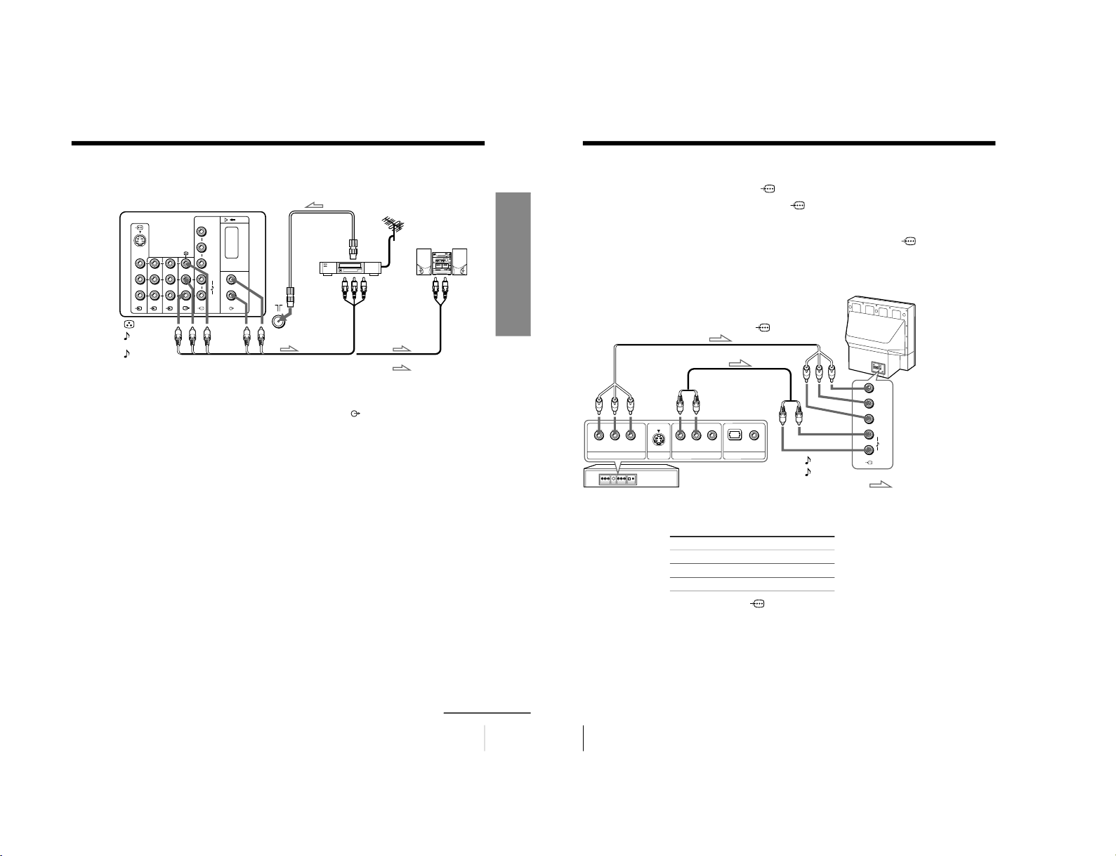
Using Your New Projection TV
: Signal flow
IEC connector
(not supplied)
or
Antenna cable (not supplied)
Antenna cable (not supplied)
Rear of
projection TV
To video and
audio outputs
To S video
output
Audio/Video cable
(not supplied)
S video cable
(not supplied)
: Signal flow
To
(S video input)
VCR
Antenna cable (not supplied)
To antenna
output
To 8 (antenna)
Rear of
projection TV
To t 1, 2 or 3 (video input)
(yellow)
-L (MONO) (white)
-R (red)
continued
Getting Started
Step 1
Connect the antenna
If you wish to connect a VCR, see the “Connecting a VCR” diagram below.
CAUTION
Do not connect the power cord until all other connections are
complete; otherwise, a minimal current leakage through the antenna
and/or other terminals to the ground could occur.
Connecting a VCR
To play a video tape, press t (see page 14).
6
Using Your New Projection TV
M
E
N
U
E
N
T
E
R
M
E
N
U
EN
TE
R
L
R
4
(
M
O
N
O
)
1
AUTO PROGRAM
01
TV SYS : AUTO
VHF LOW
PR
:
Getting Started (continued)
Inside the lower
right side panel
KP-ES61/53/48
2
1
Inside the
lower panel
KP-ES43
Notes
• If you connect a monaural VCR, connect the yellow plug to
(the yellow
jack) and the black plug to
-L (MONO) (the white jack).
• If you connect a VCR to the 8 (antenna) terminal, preset the signal
output from the VCR to the program number 0 on the projection TV.
• When both the
(S video input) and t 1 (video input) are connected,
the
(S video input) is automatically selected. To view the video input
to t 1 (video input), disconnect the S video cable.
Step 2
Insert the batteries into
the remote
Notes
• Do not use old batteries or different types of batteries together.
• To operate some of the functions of your projection TV, you may have to
open the remote control cover.
Step 3
Preset the channels automatically
from the Operating Instruction Manual. The page numbers of
the Operating Instruction Manual remain as in the manual.
– 9 –
SECTION 2
GENERAL

7
Using Your New Projection TV
Using Your New Projection TV
MENU
ENTER
M
E
N
U
E
N
T
E
R
L
R
4
(
M
O
N
O
)
Notes
• To stop the automatic channel presetting, press MENU twice.
• If your projection TV has preset an unwanted channel or cannot preset a
particular channel, then preset your projection TV manually (see page 44).
• To open the lower panel of your projection TV, push on it, then it will
open.
Step 4
Adjusting the convergence automatically
Note
• Adjust convergence about 20 – 30 minutes after the projection TV is first
turned on.
The Digital Quick Focus feature allows you to adjust the convergence
automatically.
Inside the lower
right side panel
Inside the
lower panel
KP-ES61/53/48
KP-ES43
M
E
N
U
E
N
T
E
R
L
R
4
(M
O
N
O
)
KP-ES61/53/48
KP-ES43
8
Using Your New Projection TV
L
R
4
(MONO)
Connecting optional components
You can connect optional audio/video components, such as a VCR, multi disc player,
camcorder, video game, or stereo system. To watch and operate the connected
equipment, see pages 14 and 28.
Connecting a camcorder/video game equipment
using the t (video input) jacks
Notes
• When connecting video game equipment, display the “FEATURE” menu
and select “ON” for “GAME MODE” to adjust the picture setting that is
suitable for video games (see page 39).
• You can also connect video equipment to the t 1, 2, or 3 (video input)
jacks at the rear of your projection TV.
• When both the
(S video input) and t 4 (video input) are connected,
the
(S video input) is automatically selected. To view the video input
to t 4 (video input), disconnect the S video cable.
: Signal flow
To S video output
Inside the lower
left side panel
Camcorder
Video game equipment
To video and
audio outputs
To
(S video input)
To
t
4
(video input)
or
Audio/Video cable
(not supplied)
S video cable
(not supplied)
L
R
4
(
M
O
N
O
)
M
E
N
U
E
N
T
E
R
L
R
4
(
M
O
N
O
)
: Signal flow
Camcorder
Video game equipment
To video and
audio outputs
To
(S video input)
To
t
4
(video input)
Audio/Video cable
(not supplied)
S video cable
(not supplied)
Rear of
projection TV
Inside the
lower panel
Rear of
projection TV
To S video output
or
KP-ES43
KP-ES61/53/48
– 10 –
9
Using Your New Projection TV
Using Your New Projection TV
Connecting audio/video equipment using the T
(monitor output) jacks
Notes
• If you select “DVD” on your TV screen, no signal will be output at the T
(monitor output) jacks (see page 14).
• When connecting the audio cable to the
, you can adjust the volume
with 2 +/–.
Y
C
B
/
B-Y
C
R
/
R-Y
R
L
R
L
30W MAX 16
1
2
3
3
#
C –
(yellow)
-L (MONO)
(white)
-R (red)
Rear of projection TV
To
antenna
output
To video
and audio
inputs
or
Audio system
To
audio
inputs
VCR
: Signal flow
To T
(monitor
output)
Antenna cable (not supplied)
Audio cable
(not supplied)
Audio/Video cable (not supplied)
continued
10
Using Your New Projection TV
VIDEO
COAXIAL
OPTICAL
R-AUDIO-L
LINE OUT
Y
COMPONENT VIDEO OUT
S VIDEO OUT
CB C
R
DIGITAL OUT
Y
C
B
/
B-Y
C
R
/
R-Y
R
L
Connecting a DVD player to
(component video input)
1 Using an audio cable, connect R and L under
(component video input) on your
projection TV to the LINE OUT, AUDIO R and L output connectors on your DVD
player.
2 Using a component video cable, connect Y, C
B
/B-Y, and C
R
/R-Y under
(component video input) on your projection TV to the COMPONENT VIDEO OUT
Y, C
B
, and C
R
output connectors on your DVD player.
3 Press t on the remote or the projection TV until “DVD” appears on the screen.
To component
video output
Component video cable
(not supplied)
DVD
player
To
-
L (white)
-
R (red)
To audio
output
Audio cable
(not supplied)
: Signal flow
To
(component video input)
Rear of
projection TV
Notes
• Some DVD player terminals may be labeled differently:
• When connecting to
(component video input) on your projection TV,
you must connect Y, C
B
, and C
R
to receive the video signals, and at least
connect L and R to receive analog audio signals.
Connect To (on the DVD player)
Y (green) Y
C
B
/B-Y (blue) C
b
, B-Y or P
B
C
R
/R-Y (red) C
r
, R-Y or P
R
Connecting optional components (continued)
– 11 –

11
Using Your New Projection TV
Using Your New Projection TV
VIDEO
R-AUDIO-L
LINE OUT
1 2
3
C
Connecting a DVD player to t (video input)
Connect t 1, 2, or 3 (video input)
/
(audio/video) connectors on your projection
TV to LINE OUT on your DVD player.
To audio/video
output
(yellow)
-L (MONO)
(white)
-R (red)
To t 1, 2, or 3
(video input)
: Signal flow
Audio/Video cable
(not supplied)
Notes
• Since the high quality pictures on a DVD disc contain a lot of information,
picture noise may appear. In this case, adjust the sharpness (“SHARP”)
under “PERSONAL ADJUST” in the “PICTURE MODE” menu (see
page 34).
• Connect your DVD player directly to your projection TV. Connecting the
DVD player through other video equipment will cause unwanted picture
noise.
Connecting an amplifier with Dolby
*
Pro Logic
decoder to
C– (center speaker input)
Connect the speaker terminals on your amplifier to
C– on your projection TV.
Note
• When making connection to
C– on your projection TV set
“SPEAKER: CENTER IN” in the “A/V CONTROL” menu. (see page 33)
* Manufactured under license from Dolby Laboratories Licensing
Corporation.
DOLBY, the double-D symbol ; and ”PRO LOGIC” are trademarks of
Dolby Laboratories Licensing Corporation.
Rear of
projection TV
Rear of
projection TV
to
C– (center speaker
inputs)
Amplifier with Dolby
Pro Logic decoder
Rear
speaker
(L)
Front
speaker
(L)
Front
speaker
(R)
Rear
speaker
(R)
DVD
player
12
Using Your New Projection TV
Installing the projection TV
For the best picture quality, install the projection TV within the areas below.
Optimum viewing area
(Horizontal)
KP-ES43
KP-ES61/53/48
Optimum viewing area
(Vertical)
KP-ES43
KP-ES61/53/48
60°
60°
min. 2.4 m (8 ft.) 53
”
min. 2.1 m (7 ft.) 48
”
min. 2.7 m (9 ft.) 61
”
min. 2.4 m (8 ft.) 53
”
min. 2.1 m (7 ft.) 48
”
min. 2.7 m (9 ft.) 61
”
60°
60°
20°
20°
min. 1.9 m
(6 ft.) 43
”
min. 1.9 m
(6 ft.) 43
”
20°
20°
– 12 –

13
Using Your New Projection TV
Using Your New Projection TV
TV
123
456
78
0
9
MENU PROGR
ENTER
PRESET
VTR 1 2 3 DVD
JUMP
A/B
DRC-MF
PROGR
INDEX
PIC
MODE
SOUND
MODE
PIP
PROGR
+
PIP
PROGR
–
1
Press ! to turn on the
projection TV.
When the projection TV is in
standby mode (the 1 indicator on
the projection TV is lit red), press
!/1 on the remote.
2
Press PROGR +/– or the number
buttons to select the TV
channel.
For double digit numbers, press
-, then the number (e.g., for 25,
press -, then 2 and 5).
Note
• When you turn on the projection TV, either the program number or video
mode is displayed for approximately 40 seconds. The ECO MODE (
)
icon will also appear if “ECO MODE “ in the “FEATURE” menu is set
“ON” (see page 39).
To select a TV program quickly
(1) Press and hold PROGR +/–.
(2) Release PROGR +/– when the desired program number appears.
Note
• When you select a TV program quickly, the picture may be disrupted.
This does not indicate a malfunction.
Number
buttons
PROGR
+/–
Watching the TV
This section explains various functions
and operations used while watching the
TV. Most operations can be done using
the remote.
123
456
78
0
9
JUMP
PROGR
continued
or
KP-ES61/53/48 KP-ES43
PROGR
R
PROGR
R
1 indicator
1 indicator
14
Using Your New Projection TV
TV
123
456
78
0
9
MENU PROGR
ENTER
PRESET
VTR 1 2 3 DVD
JUMP
A/B
DRC-MF
PROGR
INDEX
PIC
MODE
SOUND
MODE
PIP
PROGR
+
PIP
PROGR
–
TITLE
DRC-MF
VIDEO
To
Turn off temporarily
Turn off completely
Adjust the volume
Mute the sound
Watch the video input
(VCR, camcorder, etc.)
Jump back to the previous channel
Display the on-screen information*
Additional tasks
JUMP
MENU
ENTER
2 +/–
* Some picture/sound settings, and either the program number or video
mode are displayed. The on-screen display for the picture/sound settings
disappears after about 3 seconds.
Press
@/1.
The 1 indicator on the projection TV lights up red.
! on the projection TV.
2 +/–.
%.
t (or t on the projection TV) to select “VIDEO 1”,
“VIDEO 2”, “VIDEO 3”, “VIDEO 4” or “DVD”.
To return to the TV screen, press a (or t on the
projection TV).
JUMP.
.
Watching the TV (continued)
KP-ES61/53/48 KP-ES43
PROGR
R
PROGR
R
1 indicator
1 indicator
– 13 –

15
Using Your New Projection TV
Using Your New Projection TV
.
TV
456
78
0
9
MENU PROGR
ENTER
PRESET
VTR 1 2 3 DVD
JUMP
PROGR
INDEX
PIC
MODE
SOUND
MODE
PIP
PROGR
+
PIP
PROGR
–
/ LANGUAGE
SET UP
:
ENGL I SH
CH I L D LOCK
FAVORI TE C
INTELLIGEN
LANGUAGE/
SET UP
:
ENGL I SH
C
HILD LOCK
:
PR0 1 OF F
F
F
FAVOR I TE CH
INTELLIGE
NT VOL
:
O
LANGUAGE
MENU
To move
To confirm
A/V CONTROL
DRC-MF: DRC1250
SPEAKER:MAIN
PICTURE MODE: DYNAMIC
SOUND MODE: DYNAMIC
continued
Using the Remote Control Button Joystick (
)
You can select the menu item on the
screen by moving up, down, left or
right (see page 32).
To confirm a selected item, press
.
You can also press ENTER on the remote
to confirm a selected item.
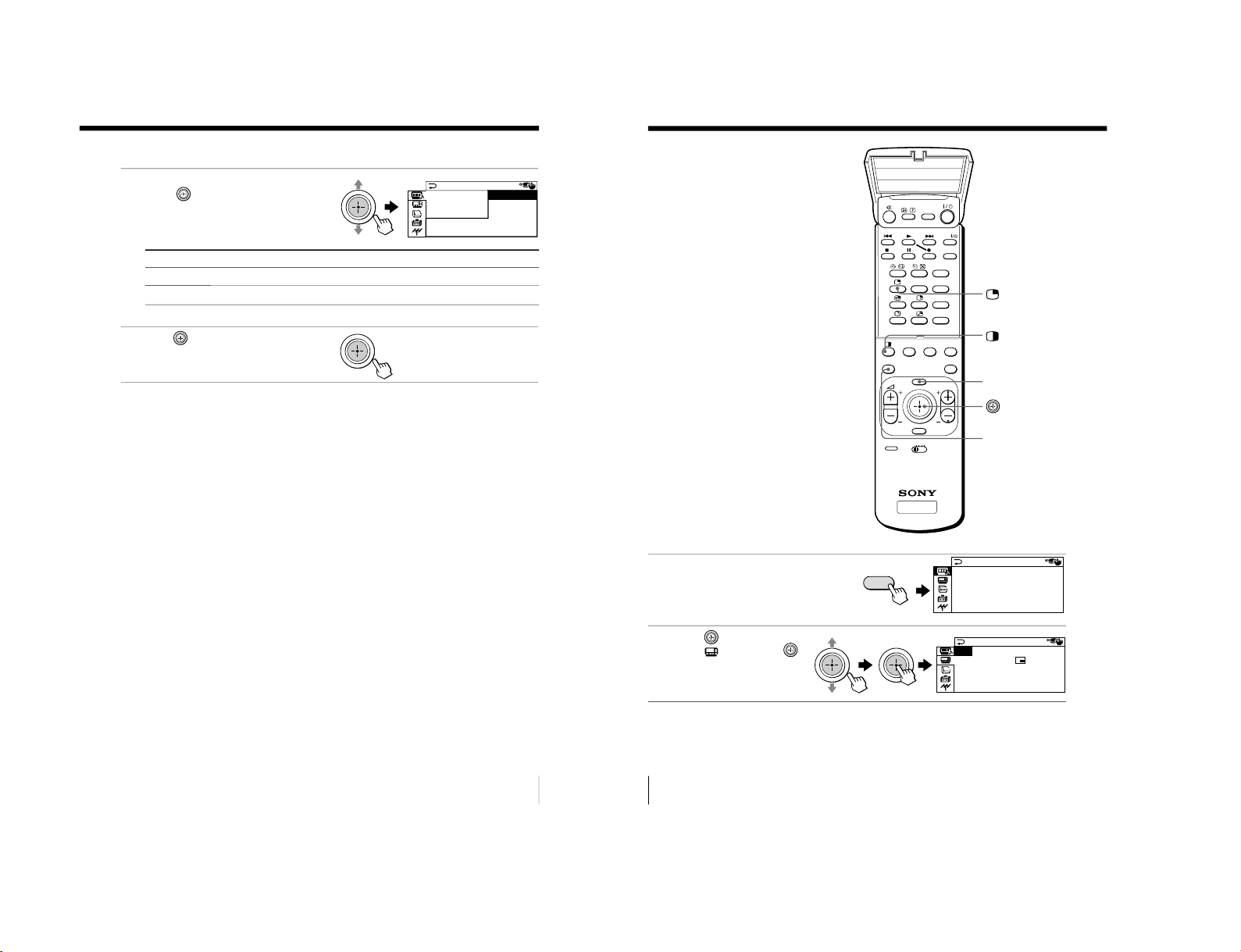
Changing the menu language
You can change the menu language as well as the on-screen language. For details on
how to use the menu, see “Introducing the menu system” on page 30.
1
Press MENU.
2
Move
up or down to
select
, then press .
3
Make sure “LANGUAGE”
is selected then press
.
4
Move
up or down to
select the desired
language (e.g.,“
”),
then press
.
The selected menu
language appears.
To return to the normal screen
Press MENU.
16
Using Your New Projection TV
SLEEP TIMER:30M
SLEEP TIMER:60M
SLEEP TIMER:OFF
SLEEP TIMER:90M
After 30 minutes
No Sleep Timer
After 60 minutes
After 90 minutes
WAKE UP TIMER:10M
WAKE UP TIMER:OFF
WAKE UP TIMER:12H00M
After 10 minutes
No Wake Up Timer After 12 hours
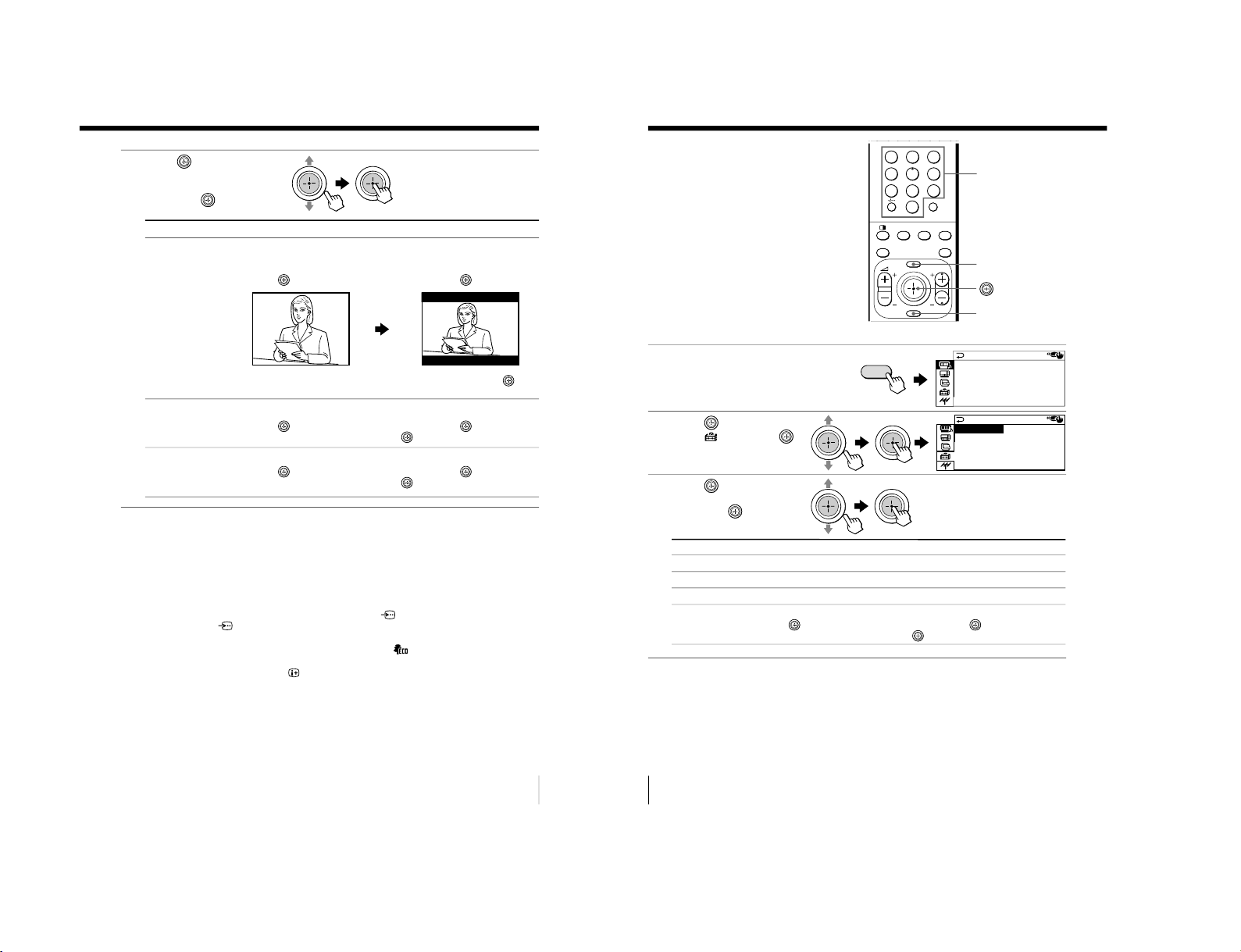
Setting the Wake Up timer
1
Press
until the desired
period of time appears.
The Wake Up timer starts
immediately after you
have set it.
2
Select the TV channel or video mode you want to wake up to.
3
Press !/1, or set the Sleep timer if you want the projection TV to turn off
automatically.
The
indicator on the projection TV lights up orange.
To cancel the Wake Up timer
Press
until “WAKE UP TIMER: OFF” appears, or turn the
projection TV off.
Note
• If no buttons or controls are pressed for more than two hours after the
projection TV is turned on using the Wake Up timer, the projection TV
automatically goes into standby mode. To resume watching the TV, press
any button or control on the projection TV or the remote.
Setting the Sleep timer
Press
until the desired
period of time appears.
The Sleep timer starts
immediately after you
have set it.
To cancel the Sleep timer
Press
until “SLEEP TIMER: OFF” appears, or turn the projection
TV off.
Watching the TV (continued)
– 14 –

17
Advanced Operations
9
DYNAMIC
9
PERSONAL
9
SOFT
9
DRAMA
SOUND
MODE
PERSONAL
DYNAMIC
HI-FINE
STANDARD
PIC
MODE
MENU PROGR
ENTER
PRESET
VTR 1 2 3 DVD
PROGR
INDEX
PIC
MODE
SOUND
MODE
PIP
PROGR
+
PIP
PROGR
–
Advanced Operations
Selecting the picture mode
Press PIC MODE
repeatedly until the
desired picture mode is
selected.
Select
“DYNAMIC”
“STANDARD”
“HI-FINE”
“PERSONAL”
To
receive high contrast pictures.
receive normal pictures.
receive higher resolution pictures with mild contrast.
receive the last adjusted picture setting from the “ADJUST” option in the
“A/V CONTROL” menu (see page 34).
Selecting the sound mode
Press SOUND MODE
repeatedly until the
desired sound mode is
selected.
Select
“DYNAMIC”
“DRAMA”
“SOFT”
“PERSONAL”
To
listen to dynamic and clear sound that emphasizes both the low and high
tones.
listen to sound that emphasizes voice and high tones.
receive soft sound.
receive the last adjusted sound setting from the “ADJUST” option in the
“A/V CONTROL” menu (see page 34).
Tip
• You can also set the picture and sound modes using the menu (see
“Changing the “A/V CONTROL” setting” on page 33).
Advanced Operations
Selecting the picture
and sound modes
You can select picture and sound modes
and adjust the setting to your preference
in the “PERSONAL” option.
SOUND MODE
PIC MODE
18
Advanced Operations
Viewing higher
quality pictures
— “DRC-MF”
The Digital Reality Creation-Multi
Function (DRC-MF) feature allows you
to enjoy higher quality pictures on your
projection TV. You can select
“DRC1250” to watch super real (higher
resolution) pictures, or “DRC100” to
reduce flicker if necessary.
Press DRC-MF repeatedly
until you receive the
desired picture quality.
Tip
• When the broadcast signal is weak, you may see some dots or noise on the
TV screen. To reduce this interference, display the “A/V CONTROL”
menu and select “ADJUST” in “PICTURE MODE”, then adjust “SHARP”
to reduce the sharpness (see page 34).
Note
• The DRC-MF mode is not selectable when using the “PROGRAM INDEX”
or “FAVORITE CH” feature, or when the “GAME MODE”, Picture-InPicture (“PIP”), or “TWIN” mode is turned “ON”.
The DRC-MF logo (
) and “DRC-MF” are trademarks of
Sony Corporation.
DRC-MF: DRC1250 DRC-MF: DRC100
DRC-MF
123
456
78
0
9
MENU PROGR
ENTER
JUMP
A/B
DRC-MF
PROGR
INDEX
PIC
MODE
SOUND
MODE
PIP
PROGR
+
PIP
PROGR
–
Select
“DRC1250”
“DRC100”
To
select higher resolution pictures.
reduce flicker on the screen.
DRC-MF
– 15 –

19
Advanced Operations
TV
TITLE
PROGR
MENU
ENTER
DRC-MF
FAVORITE
PROGR
INDEX
PIC
MODE
SOUND
MODE
PRESET
VTR 1 2 3 DVD
VIDEO
PIP
PROGR
+
PIP
PROGR
–
FAVORITE
ENTER
FAVORITE CH
7.PR 12 6.PR 10 5.PR 08 4.PR 06
3.PR 04
2.PR 03
1.PR 01
8
1
3
4
12 10 8 6
FAVORITE CH
1
3
4
12 10 8 6
FAVORITE
FAVORITE CH
Viewing your
favorite channels
— “FAVORITE CH”
You can display seven favorite channels
for quick and easy selection.
The last seven channels selected with
the number buttons are displayed in
“AUTO” mode. You can set up your
own favorite channels in “MANUAL”
mode under the “FAVORITE CH” menu
(see “Changing the favorite channel
setting” on page 42).
Selecting a favorite channel
1
Press FAVORITE.
2
Move
up, down, left or
right to select the desired
channel (e.g. PR 8), then
press
.
3
Press
again.
Note
• When you use your projection TV for the first time, seven preset channels
appear.
20
Advanced Operations
10 12
12
TITLE
PROGR
MENU
ENTER
DRC-MF
FAVORITE
PROGR
INDEX
PIC
MODE
SOUND
MODE
VIDEO
PIP PROGR +/
PIP PROGR –
PIP
PROGR
+
PIP
PROGR
–
Displaying the PIP screen
Press
.
Displaying TWIN pictures
Press
.
To return to the normal screen
Press
(when in the PIP screen) or
(when in the TWIN picture
screen).
Tip
• You can also display the PIP screen or TWIN pictures using the menu (see
“Changing the MULTI PICTURE setting” on page 36).
Watching two
programs at the
same time
— “PIP”, “TWIN”
With the Picture-in-Picture (PIP) or
TWIN pictures features, you can display
a different TV program or video within
or beside the main picture.
– 16 –
21
Advanced Operations
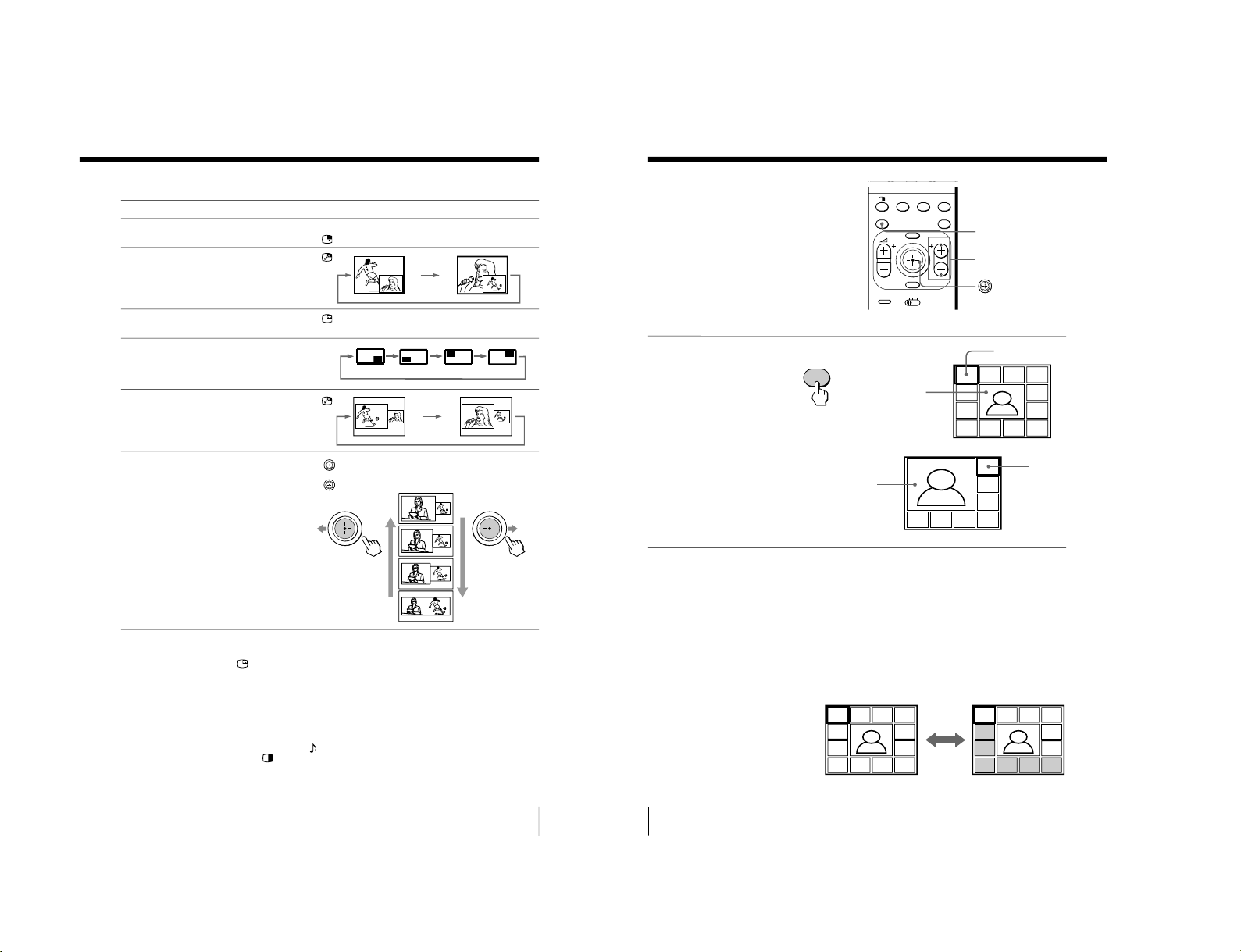
Additional PIP/TWIN pictures tasks
To
change a TV program in the PIP
screen or in the right TWIN picture
swap pictures between the main
and PIP screens
freeze the PIP screen
change the position of the PIP screen
swap the right and left pictures of
the TWIN pictures
change the screen size of the TWIN
pictures
Notes
• The
button does not function in the TWIN pictures mode.
• When you display a video input on the PIP screen at a faster/slower
speed, the picture may be disrupted depending on the VCR type.
• If you display different color systems on the main screen and the PIP
screen, the size of the PIP screen may be different and the PIP picture may
be disrupted. This does not indicate a malfunction of the projection TV.
• In the TWIN picture screen, you can only operate and hear the sound of
the main left screen ( appears on the screen).
• When the
button is pressed, the TV screen flickers or goes blank for
about one second before the TWIN pictures appear. This does not indicate
a malfunction of the projection TV.
Press/Move
Press PIP PROGR + or PIP PROGR –. For a video input,
press
.
Press
.
Press
.
To unfreeze the screen, press the button again.
Press D
.
Press
.
Move left to increase the left screen size.
Move
right to increase the right screen size.
22
Advanced Operations
16
1
234
12 5
11 6
10 9 8 7
16
13
14 15 16
17
18
Displaying
multiple
programs
— “PROGRAM INDEX
”
The PROGRAM INDEX feature displays
all of the preset TV programs on twelve
or seven sub screens for direct selection.
Press PROGR INDEX.
The first twelve preset
programs appear one by
one, clockwise from the
upper left corner.
When the number of the
preset TV programs is less
than eight, the first seven
preset programs appear
one by one, clockwise from
the upper right corner.
Tip
• When you press the PROGR INDEX button in the TWIN pictures mode,
the left picture appears as the main screen of the PROGRAM INDEX
mode.
To view the next or the previous twelve preset programs
This works only when the number of the preset TV programs is
more than twelve.
Press PROGR +/– on the remote or the projection TV.
16
1
2
3
7654
16
1
234
12 5
11 6
10987
0
MENU PROGR
ENTER
PRESET
VTR 1 2 3 DVD
PROGR
INDEX
PIC
MODE
SOUND
MODE
PIP
PROGR
+
PIP
PROGR
–
PROGR INDEX
b
PROGR +/–
Main screen
Main screen
Sub screens
Sub
screens
PROGR
INDEX
– 17 –
23
Advanced Operations
8
8
1
234
12 5
11 6
10987
16
1
234
12 5
11 6
10987
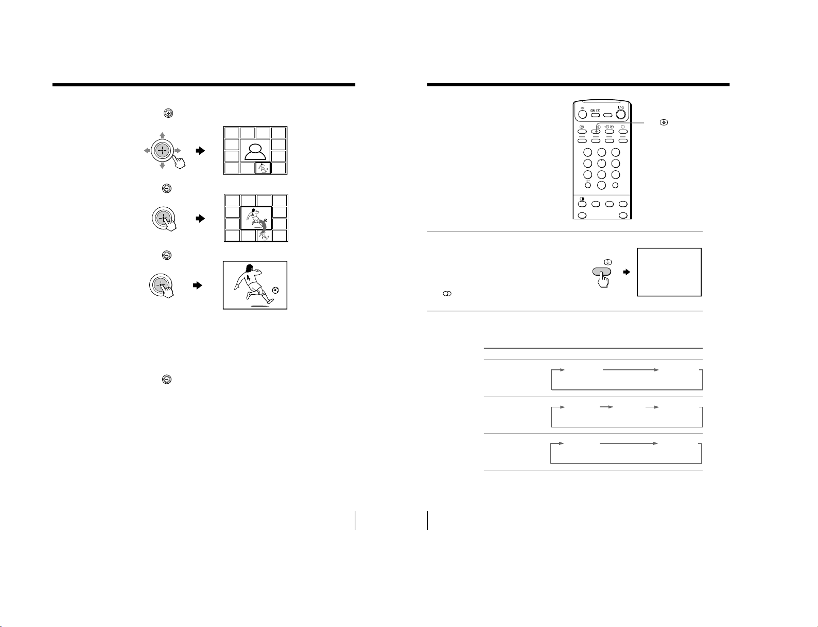
To select the desired program directly from the sub screens
1 Move up, down, left or right to move the frame to the screen
of the program you want to watch.
2 Press
.
3 Press
again.
Tip
• Pressing the number buttons directly displays the program.
To return to the normal screen
Press PROGR INDEX again, or:
1 Select “PROGRAM INDEX” from the “MULTI PICTURE” menu.
2 Press
.
Tip
• You can also display multiple programs using the menu (see “Changing
the MULTI PICTURE setting” on page 36).
Note
• When displaying multiple programs, only the sound of the main screen is
heard.
24
Advanced Operations
Enjoying stereo or
bilingual
programs
You can enjoy stereo sound or bilingual
programs of NICAM and A2 (German)
stereo systems.
Press A/B repeatedly until
you receive the sound you
want.
The on-screen display
changes to show the
selected sound and the
indicator on the
projection TV lights up red.
When receiving a NICAM program
NICAM
MONO
(Stereo sound)
(Regular sound)
NICAM
MAIN
MONO
(Main sound)
(Regular sound)
NICAM
SUB
(Sub sound)
NICAM
MAIN
MONO
(Main sound)
(Regular sound)
NICAM
A/B
123
456
78
0
9
JUMP
A/B
DRC-MF
PROGR
INDEX
PIC
MODE
SOUND
MODE
PIP
PROGR
+
PIP
PROGR
–
A/B
Broadcasting On-screen display (Selected sound)
NICAM stereo
NICAM bilingual
NICAM monaural
– 18 –

25
Advanced Operations
STEREO
MONO
(Stereo sound)
(Regular sound)
MAIN
SUB
(Main sound)
(Sub sound)
MONO
AUTO
When receiving an A2 (German) program
Receiving area for NICAM and A2 (German) programs
Notes
• If the signal is very weak, the sound becomes monaural automatically.
• If the stereo sound is noisy when receiving a NICAM program, select
“MONO”. The sound becomes monaural, but the noise is reduced.
• Before receiving a NICAM stereo program in China, please check the
NICAM broadcast condition at your area. When receiving a NICAM
stereo program, the receiving conditions might vary depending on area. In
addition, different strength of the NICAM broadcast signal might affect
the receiving quality.
If the sound is distorted or noisy when receiving a monaural
program through the 8 (antenna) terminal
Press A/B repeatedly until “MONO” appears on the screen.
To cancel the monaural sound setting, press A/B again until
“AUTO” appears on the screen.
Notes
• The “MONO” or “AUTO” setting is memorized for each program
position.
• You cannot receive a stereo broadcast signal when the projection TV is in
the “MONO” setting. Normally, set the projection TV to “AUTO”.
Broadcasting On-screen display (Selected sound)
A2 (German) stereo
A2 (German) bilingual
System
NICAM
A2 (German)
Receiving area
Hong Kong, Singapore, New Zealand, Malaysia,
Thailand, etc.
Australia, Malaysia, Thailand, etc.
26
Advanced Operations
TV
TITLE
VIDEO
FAVORITE
PROGR
MENU
ENTER
DRC-MF
FAVORITE
PROGR
INDEX
PIC
MODE
SOUND
MODE
SURROUND
PRESET
VTR 1 2 3 DVD
TV
123
456
78
0
9
MENU PROGR
ENTER
PRESET
VTR 1 2 3 DVD
JUMP
A/B
DRC-MF
FAVORITE
PROGR
INDEX
PIC
MODE
SOUND
MODE
SURROUND
A/B
(red, green,
yellow, blue)
P166 SECTEXT 166 FR1 MAR 03:59:09
From Singapore
To PARIS
To OSAKA
To ROMA
To SYDNEY
Day Dep/Arr Flight Alrcraft
1.6 220/0588 SQ28 747
2 2130/1225 PA115 L15
3 2115/1330 SQ26 747
2.7 2130/0745 SQ24
747
4 2300/0915 AZ487 747
2.5 1000/1715 SQ6 747
4.6 0930/2015 CX522 L10
1 2210/0610 SQ21A 747
2 2100/0835 SQ21A 747
Viewing Teletext
Some TV stations broadcast an
information service called Teletext
which allows you to receive various
information, such as stock market
reports and news.
Displaying Teletext
1
Select a TV channel that carries the Teletext broadcast you want to watch.
2
Press
to display the
text.
A Teletext page (normally
the index page) is
displayed. If there is no
Teletext broadcast, “100?”
is displayed at the top left
corner of the screen after
approximately 10 seconds.
To turn off Teletext
Press a.
– 19 –

27
Advanced Operations
Additional Teletext tasks
To
display a Teletext page on the TV
picture
check the contents of a Teletext service
select a Teletext page
hold (pause) a Teletext page
(stop the page from scrolling)
reveal concealed information
(e.g., an answer to a quiz)
enlarge the Teletext display
stand by for a Teletext page while watching
a TV program
* You can also select a Teletext page of any page number that appears in the
colored column at the bottom of the screen using the corresponding colorcoded button on the remote.
Using FASTEXT
This feature allows you to quickly access a Teletext page that uses
FASTEXT. When a FASTEXT program is broadcast, colored menus
appear at the bottom of the screen. The color of each menu
corresponds to the color-coded buttons on the remote (red
,
green
, yellow
, and blue
).
To access a FASTEXT menu
Press the color-coded button on the remote corresponding to the
menu you want. The menu page appears on the screen after a few
seconds.
Do this
Press
.
Each time you press
, the screen changes as
follows: Teletext t Teletext and TV t TV.
Press .
An overview of the Teletext contents, including
page numbers, appears on the screen.
Press the number buttons to enter the three-digit
page number of the desired Teletext page.* If you
make a mistake, reenter the correct page number. To
access the next or previous page, press PROGR +/–.
Press
to display the symbol “z” at the top left
corner of the screen. To resume normal Teletext
viewing, press
or
.
Press
.
To conceal the information, press the button again.
Press
.
Each time you press
, the Teletext display
changes as follows: Enlarge upper half t Enlarge
lower half t Normal size.
1 Enter the Teletext page number that you want to
refer to, then press
.
2 When the page number is displayed, press
to
show the text.
28
Advanced Operations
Operating
optional
components
You can use the supplied remote to
operate Sony video equipment such as
Beta, 8 mm, VHS or DVD.
Setting up the remote to work with other
connected equipment
Switch VTR to select the
desired equipment type
(see the chart below).
Notes
• If your video equipment is furnished with a COMMAND MODE selector,
set this selector to the same position as the VTR switch.
• If the equipment does not have a certain function, the corresponding
button on the remote will not operate.
VTR 1 2 3 DVD
TITLE
PROGR
MENU
ENTER
DRC-MF
FAVORITE
PROGR
INDEX
PIC
MODE
SOUND
MODE
PRESET
VTR 1 2 3 DV D
VIDEO
PIP
PROGR
+
PIP
PROGR
–
To control
DVD
VTR1 (Beta)
VTR2 (8 mm)
VTR3 (VHS)
For example, to operate a
Sony 8 mm VCR:
Select
DVD
1
2
3
VIDEO I/1
Video equipment
operation buttons
VTR
MENU
– 20 –

29
Advanced Operations
Operating a VCR using the remote
Operating a DVD player using the remote
To
turn on/off
record
play
stop
fast forward (M)
rewind the tape (m)
pause
search the picture forward (M)
or backward (m)
Press
VIDEO I / 1
N while pressing z.
N
x
>
.
X
Press again to resume normal playback.
> or .during playback.
Release to resume normal playback.
To
turn on/off
play
stop
pause
step through different tracks of an
audio disc
display the title menu
display the menu
select the menu item
Press
VIDEO I / 1
N
x
X
Press again to resume normal playback.
> to step forward or . to step backward.
TITLE
MENU while holding down z.
Move
up, down, left or right while holding
down z.
30
Adjusting Your Setup (MENU)
SET UP
:
ENGL I SH
CH I LD L OCK
FAVORI TE C
INTELLIGEN
LANGUAGE/
Level 1
“A/V
CONTROL”
“MULTI
PICTURE”
“FEATURE”
Adjusting Your Setup (MENU)
Return icon
CH PRESET icon
SET UP icon
MULTI PICTURE icon
Name of the current
menu
A/V CONTROL icon
Level 2
“DRC-MF”
“PICTURE MODE”
“ADJUST”
“SOUND MODE”
“ADJUST”
“SPEAKER”
“PIP”
“PIP POSITION”
“SWAP”
“TWIN”
“PROGRAM INDEX”
“WIDE MODE”
“ECO MODE”
“GAME MODE”
Level 3/Function
Select the “DRC-MF” mode:
“DRC1250” t “DRC100”
Select the picture mode:
“DYNAMIC” t “STANDARD” t “HI-FINE” t
“PERSONAL” t “ADJUST”
Adjust the “PERSONAL” option:
“PICTURE” t “COLOR” t “BRIGHT” t “HUE” t
“SHARP”
Select the sound mode:
“DYNAMIC” t “DRAMA” t “SOFT” t
“PERSONAL” t “ADJUST”
Adjust the “PERSONAL” option:
“BASS” t “TREBLE” t “BALANCE”
Select the “SPEAKER” mode:
“MAIN” t “CENTER IN”
Activate or deactivate the PIP feature.
Change the position of the sub screen.
Swap the pictures between the main and sub screens.
Display a TV program or video beside the main screen.
Display all the preset TV programs at the same time.
Activate or deactivate WIDE MODE feature.
Activate or deactivate ECO MODE feature.
Activate or deactivate GAME MODE feature.
Introducing the menu system
The MENU button lets you open a menu and change the settings of your projection
TV. The following is an overview of the menu system.
Menu level 3
Menu level 2
Guide mark icon
FEATURE icon
Menu level 1
– 21 –
31
Adjusting Your Setup (MENU)
Level 1
“SET UP”
“CH PRESET”
Level 2
“LANGUAGE”
“CHILD LOCK”
“FAVORITE CH”
“INTELLIGENT
VOL”
“AUTO
PROGRAM”
“MANUAL
PROGRAM”
“SKIP”
“TV SYS”
“COL SYS”
Level 3/Function
Change the menu language:
“ENGLISH” t “
” (Chinese) t “
” (Arabic)
Lock out specific channels.
Set favorite channels.
Adjust the volume automatically.
Preset channels automatically.
Preset channels manually.
Skip unwanted or unused program numbers.
Select the TV system:
“B/G” t “I” t “D/K” t “ M”
Select the color system:
“AUTO” t“ PAL” t “SECAM” t “NTSC3.58” t
“NTSC4.43”
Adjusting Your Setup (MENU)
continued
32
Adjusting Your Setup (MENU)
ENTER
MULT I PI CTURE
:
:
OFF
SWAP
TWI N:OFF
PROGRAM I NDEX
PIP POSITION
PIP
MUL T I P I CT UR E
:
:
OFF
SWAP
TWI N:OFF
PROGRAM I NDEX
PIP
PIP POSITION
MENU
A/V CONTROL
DRC-MF: DRC1250
SPEAKER:MAIN
PICTURE MODE: DYNAMIC
SOUND MODE: DYNAMIC
TV
MENU PROGR
ENTER
PRESET
VTR 1 2 3 DVD
.
PROGR
INDEX
PIC
MODE
SOUND
MODE
PIP
PROGR
+
PIP
PROGR
–
How to use the menu
Move the button
joystick (
) up,
down, left or right
to select the desired
item.
Press the button
joystick (
) to
confirm the selection
and/or go to the next
level. You can also
press ENTER on the
remote to do this.
Press MENU to display
the menu.
To
Adjust the setting value
Move to the next/previous menu level
Cancel the menu
Other menu operations
Tips
• If you want to exit from Menu level 2 to Menu level 1, move
up or
down until the return icon (3) is highlighted, then press
or ENTER.
• The MENU, ENTER, and
2
+/– buttons on the projection TV can also be
used for the operations above.
• The V + and v – buttons on the projection TV can also be used instead of
moving the button joystick (
) up or down.
Note
• If more than 60 seconds elapse between entries, the menu screen
automatically disappears.
Press/Move
Move
up, down, left or right.
Move left or right.
Press MENU.
or
Introducing the menu system (continued)
– 22 –

33
Adjusting Your Setup (MENU)
Changing the
“A/V
CONTROL” setting
The “A/V CONTROL” menu allows you
to adjust the picture and sound settings.
1
Press MENU.
2
Move
up or down to
select
, then press .
3
Move
up or down to
select either “DRC-MF”,
“PICTURE MODE
”, “SOUND
MODE”, or “SPEAKER”, then
press
.
4
Move
up or down to
select the desired option,
then press
.
* When the “PERSONAL” mode is selected, the last adjusted picture/sound
settings from the “ADJUST” option are received (see page 34).
A / V CONTROL
SPEAKER:MAIN
PICTURE MODE: DYNAMIC
SOUND MODE: DYNAMIC
DRC-MF: DRC1250
A/V CONTROL
DRC1250
PICTURE MODE
DRC-MF :
DRC100
SOUND MODE
SPEAKER:MAIN
A/V CONTROL
DRC-MF: DRC1250
SPEAKER:MAIN
PICTURE MODE: DYNAMIC
SOUND MODE: DYNAMIC
MENU
MENU PROGR
ENTER
MENU
Tip
• For details on the options under the “DRC-MF“, “PICTURE MODE“/
“SOUND MODE“, and “SPEAKER“ modes, see pages 18, 17 and 35
respectively.
To return to the normal screen
Press MENU.
ENTER
continued
Select
either “DRC1250“ or “DRC100“.
either “DYNAMIC“, “STANDARD“, “HI-FINE“, “PERSONAL“*, or “ADJUST“.
either “DYNAMIC“, “DRAMA“, “SOFT“, “PERSONAL“*, or “ADJUST“.
either “MAIN“ or “CENTER IN“.
For
“DRC-MF“
“PICTURE MODE“
“SOUND MODE“
“SPEAKER“
34
Adjusting Your Setup (MENU)
Adjusting the
“ADJUST” options under
“PICTURE MODE
”
1
Move
up or down to
select the desired item
(e.g., “COLOR”), then
press
.
2
Adjust the value according to the following table, then press
.
* You can adjust “HUE” for the NTSC color system only.
3
Repeat the above steps to adjust other items.
The adjusted settings will be received when you select “PERSONAL”.
Adjusting the
“ADJUST” options under
“SOUND MODE
”
1
Move
up or down to
select the desired item
(e.g., “BALANCE”), then
press
.
2
Adjust the value according to the following table, then press
.
3
Repeat the above steps to adjust other items.
The adjusted settings will be received when you select “PERSONAL”.
Changing the “A/V CONTROL” setting (continued)
For
“PICTURE”
“COLOR”
“BRIGHT”
“HUE”*
“SHARP”
Move
down or left to
decrease picture contrast
decrease color intensity
darken the picture
increase red picture tones
soften the picture
Move
up or right to
increase picture contrast
increase color intensity
brighten the picture
increase green picture tones
sharpen the picture
COLOR
08
BALANCE 00
For
“BASS”
“TREBLE”
“BALANCE”
Move
down or left to decrease the bass, up or right to increase the bass.
down or left to decrease the treble, up or right to increase the treble.
down or left to increase the left speaker’s volume, up or right to increase
the right speaker’s volume.
– 23 –
35
Adjusting Your Setup (MENU)
Setting the “SPEAKER” options
1
In the “SPEAKER” menu,
move
up or down to
select the desired option
(see table below).
2
Press
to confirm the
selected option.
Tip
• For details on the menu system and how to use the menu, refer to
“Introducing the menu system” on page 30.
A/V CONTROL
MAIN
PICTURE MODE
DRC-MF : DRC
CENTER IN
SOUND MODE
SPEAKER
To
listen to the sound from a projection TV.
use the projection TV speakers as center speakers.
Select
“MAIN“
“CENTER IN”
36
Adjusting Your Setup (MENU)
MU L T I P I CTURE
:
:
OFF
SWAP
TWI N
:
OFF
PROGRAM I NDEX
PIP POSITION
PIP
MENU
TV
TITLE
FAVORITE
PROGR
MENU
ENTER
DRC-MF
PROGR
INDEX
PIC
MODE
SOUND
MODE
PRESET
VTR 1 2 3 DVD
VIDEO
PIP
PROGR
+
PIP
PROGR
–
MENU
PROGR INDEX
A/V CONTROL
DRC-MF: DRC1250
SPEAKER: MAIN
PICTURE MODE: DYNAMIC
SOUND MODE: DYNAMIC
Changing the
“MULTI PICTURE”
setting
The “MULTI PICTURE” menu allows
you to use the Picture-in-Picture (PIP),
TWIN pictures, or PROGRAM INDEX
features.
1
Press MENU.
2
Move
up or down to
select
, then press
.
– 24 –

37
Adjusting Your Setup (MENU)
3
Move
up or down to
select the desired option
(see the table below),
then press
.
To return to the normal screen
Press MENU.
Tip
• For details on the menu system and how to use the menu, see
“Introducing the menu system” on page 30.
Select
“PIP”
“PIP POSITION”
“SWAP”
“TWIN”
“PROGRAM INDEX”
To
display the PIP screen within the main picture.
Move
up or down to select “ON”, then press
.
To cancel, press
or select “OFF”, then press
.
change the position of the PIP screen.
Move
up or down to select the desired position, then press
.
swap the main and PIP screens, or right and left pictures of the
TWIN pictures.
display a different TV program or video beside the main picture.
Move up or down to select “ON”, then press
.
To cancel, press
or select “OFF”, then press
.
view multiple programs on the sub-screens.
To cancel, press PROGR INDEX.
38
Adjusting Your Setup (MENU)
Changing the
“FEATURE” setting
The “FEATURE” menu allows you to
change the size of the picture on the
screen when receiving wide mode (16:9)
picture signals. You can also adjust the
picture setting that is suitable for
viewing video games, and reduce the
power consumption of your projection
TV.
1
Press MENU.
2
Move
up or down to
select
, then press
.
FEATURE
ECO MODE: OFF
GAME MODE: OFF
:
OFF
WIDE MODE
A/V CONTROL
DRC-MF: DRC1250
SPEAKER: MAIN
PICTURE MODE: DYNAMIC
SOUND MODE: DYNAMIC
MENU
TV
123
456
78
0
9
MENU PROGR
ENTER
PRESET
VTR 1 2 3 DVD
JUMP
A/B
DRC-MF
PROGR
INDEX
PIC
MODE
SOUND
MODE
PIP
PROGR
+
PIP
PROGR
–
MENU
ENTER
– 25 –
39
Adjusting Your Setup (MENU)
3
Move
up or down to
select the desired option
(see the table below),
then press
.
Notes
• When you turn on “ECO MODE”, the picture may become dimmer.
Turning “ECO MODE” off will restore the picture to its original setting.
• “WIDE MODE” is available only when you have selected DRC1250
(NTSC mode) in the ”A/V CONTROL” menu with video input or DVD
input.
• “WIDE MODE” and “GAME MODE” is available only when receiving
signals through the t (video input),
(S video input), or
(component video input) jacks at the front and rear of your projection
TV.
• If “ECO MODE” is on, the ECO MODE (
) icon will appear at the
bottom right corner of the screen when you turn on the projection TV or
when you press
on the remote. (See pages 13 and 14)
To return to the normal screen
Press MENU.
Tip
• For details on the menu system and how to use the menu, see
“Introducing the menu system” on page 30.
Select
“WIDE MODE”
“ECO MODE”
“GAME MODE”
To
change the size of the picture when receiving wide-mode (16:9)
picture signal.
Move
up or down to select “ON”, then press
.
To restore the normal picture size, select “OFF” then press
.
reduce power consumption of your projection TV to save energy.
Move
up or down to select “ON”, then press
.
To cancel, select “OFF”, then press .
adjust the picture setting that is suitable to view video games.
Move
up or down to select “ON”, then press
.
To cancel, select “OFF”, then press
.
40
Adjusting Your Setup (MENU)
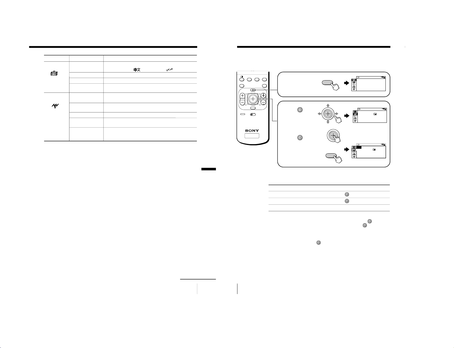
Changing the
“SET UP” setting
The “SET UP” menu allows you to:
change the menu language, block
channels, adjust the picture position,
program your favorite channels, and
adjust the volume automatically.
1
Press MENU.
2
Move
up or down to
select
, then press .
3
Move
up or down to
select the desired option,
then press
.
To return to the normal screen
Press MENU.
Select
“LANGUAGE”
“CHILD LOCK”
“FAVORITE CH”
“INTELLIGENT
VOL”
To
change the menu language (see page 15).
block channels (see page 41).
select your favorite channels (see pages 19 and 42).
adjust the volume of all TV programs automatically.
Move
up or down
to select “ON”, then press
.
To cancel, select “OFF”, then press
.
SET UP
:
ENGL I SH
C
HILD LOCK
:
PR0 1 OF F
F
F
FAVOR I TE CH
INTELLIGE
NT VOL
:
O
LANGUAGE
A / V CONTROL
DRC-MF: DRC1250
SPEAKER: MAIN
PICTURE MODE: DYNAMIC
SOUND MODE: DYNAMIC
MENU
123
456
78
0
9
MENU PROGR
ENTER
JUMP
PROGR
INDEX
PIC
MODE
SOUND
MODE
PIP
PROGR
+
PIP
PROGR
–
MENU
Number buttons
ENTER
– 26 –

41
Adjusting Your Setup (MENU)
6
SET UP
ENGL I SH
PR0 6 ON
FAVOR I TE CH
INTELLIGENT VOL
:
OFF
CH I L D LOCK
:
:
LANGUAGE
SET UP
:
LANGUAGE
E
CHILDLOCKPR06
FAVOR I TE C
ON
INTELLIGEN
OFF
123
456
78
0
9
JUMP
Blocking channels (
“CHILD LOCK”)
1
After selecting
“CHILD
LOCK”, either move
up
or down, or press the
number buttons (or
PROGR +/–) to select the
desired channel (e.g. PR 06),
then press
.
2
Move
up or down to
select “ON”, then
press
.
To unlock the channel,
select “OFF”.
The lock symbol (
)
appears on the screen when
“ON” is selected.
If a locked channel is
selected, the lock symbol
appears on the screen.
3
Repeat steps 1 and 2 to lock other channels.
To return to the normal screen
Press MENU.
Note
• If you preset a locked channel, that channel will be unlocked
automatically (see page 43).
b
or
continued
42
Adjusting Your Setup (MENU)
FAVOR I TE CH
MODE
:
MANU A L
1.PR01 5.PR09
2.PR02 6.PR11
3.PR05 7.PR13
4.PR08
FAVOR I TE CH
MODE
:
MANU A L
1.PR01 5.PR09
2.PR02 6.PR11
3.PR 7.PR13
4.PR08
06
FAVOR I TE CH
MODE
:
MANU A L
1.PR01 5.PR09
2.PR02 6.PR11
3.PR06 7.PR13
4.PR08
FAVOR I TE CH
MODE
:
AUTO AUTO
1.PR01 MANUAL
2.PR02
3.PR06
4.PR08
Changing the favorite channel setting
1
After selecting
“F
AVORITE
CH”, make sure “MODE”
is selected, then press
.
2
Move
up or down to
select “MANUAL”, then
press
.
3
Move
up or down to
select the program you
want to change, then
press
.
4
Move
up or down to
change the number, then
press
.
5
Repeat steps 3 and 4 to set other channels.
To return to the normal screen
Press MENU.
Note
• If you press the PROGR +/– buttons or number buttons in step 4 above,
the projection TV will display the channel immediately.
Changing the
“SET UP” setting (continued)
– 27 –
43
Adjusting Your Setup (MENU)
1
Press MENU.
2
Move
up or down to
select
, then press
.
3
Move
up or down to
select the desired option,
then press
.
To return to the normal screen
Press MENU.
Tip
• For details on the menu system and how to use the menu, refer to
“Introducing the menu system” on page 30.
CH PRESET
MANUAL PROGRAM
SK I P
:
PR0 2 OF F
TV SYS
:
B/G
COL S YS
:
AUTO
AUTO PROGRAM
A/V CONTROL
DRC-MF: DRC1250
SPEAKER: MAIN
PICTURE MODE: DYNAMIC
SOUND MODE: DYNAMIC
MENU
MENU PROGR
ENTER
PRESET
VTR 1 2 3 DVD
PROGR
INDEX
PIP
PROGR
–
MENU
ENTER
Select
“AUTO PROGRAM”
“MANUAL PROGRAM”
“SKIP”
“TV SYS”
“COL SYS”
To
preset channels automatically.
preset channels manually. See “Presetting channels
manually” on page 44.
skip unwanted or unused channels.
1 Either move
up or down, or press the number buttons
(or PROGR +/–) until the unused or unwanted channel
number appears, then press
.
2 Select “ON”, then press
.
3 To disable other channels, repeat steps 1 and 2.
To restore the skipped channel, select “OFF” in step 2.
select the TV system.
select the color system. Normally, set this to “AUTO”.
PRESET
continued
Changing the
“CH
PRESET” setting
The “CH PRESET” menu allows you to
adjust the setup of your projection TV.
For example, you can manually tune in a
channel with a weak signal that fails to
be tuned in by automatic presetting.
44
Adjusting Your Setup (MENU)
MANU A L P ROGRAM
PR
:
10
TV SYS
:
I
SENS
:
HIGH
VHF LOW
FINE
:
AUTO
MANU A L P ROGRAM
PR
:
10 B/G
TV SYS
:
I
SENS
:
HIG D/K
VHF LOW M
FINE
:
AUTO
MANU A L P ROGRAM
PR
:
10
TV SYS
:
B/G
SENS
:
HIGH
VHF L OW
FINE
:
AUTO
MANU A L P ROGRAM
PR
:
10
TV SYS
:
B/G
SENS
:
HIGH
VHF LOW
FINE
:
AUTO
MANU A L P ROGRAM
PR
:
10
TV SYS
:
B/G
SENS
:
HIGH
VHF L OW
FINE
:
AUTO
MANUAL PROGRAM
PR
:
06
TV SYS
:
B/G
SENS
:
HIGH
VHF L OW
FINE
:
AUTO
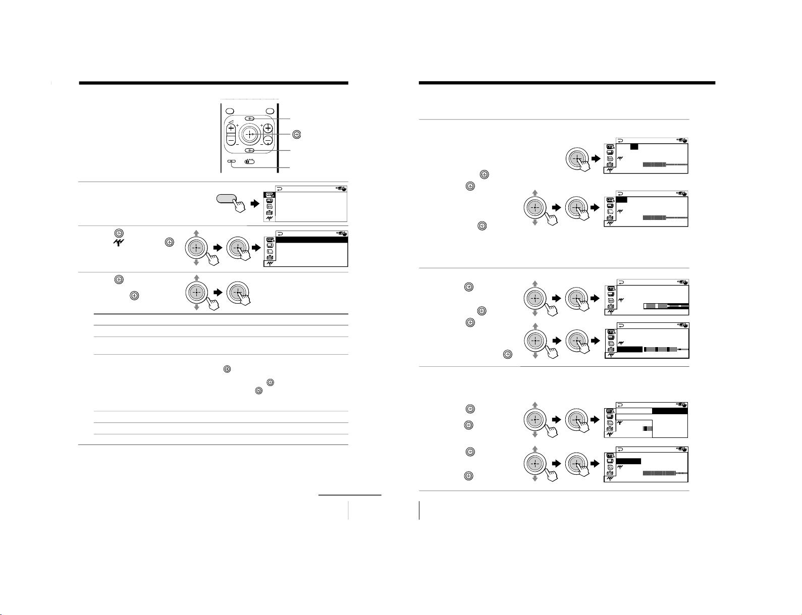
Presetting channels manually
1
After selecting
“MANUAL
PROGRAM”, select the
program number to
which you want to preset
a channel.
(1) Make sure “PR” is selected,
then press
.
(2) Move
up or down until
the program number you
want to preset (e.g.,
program number “10”)
appears on
the menu,
then press
.
Tips
• You can also select the “MANUAL PROGRAM” menu directly by pressing the
PRESET button on the remote.
• You can also select the program number with the PROGR +/– or number buttons.
2
Select the desired channel.
(1)
Move
up or down to
select either “VHF LOW”,
“VHF HIGH”, or “UHF”,
then press
.
(2) Move
up or down
until the desired
channel’s broadcast
appears on the TV
screen, then press
.
3
If the sound of the
desired channel is
abnormal, select the
appropriate TV system.
(1) Move
up or down to
select “TV SYS”, then
press
.
(2) Move
up or down
until the sound
becomes normal, then
press
.
Changing the
“CH PRESET” setting (continued)
– 28 –

45
Adjusting Your Setup (MENU)
MANU A L P ROGRAM
PR
:
10 HIGH
TV SYS
:
ILOW
SENS
:
VHF LOW
FINE
:
MA ANU
MANU A L P ROGRAM
PR
:
10
TV SYS
:
I
:
LOW
VHF L
L
OW
FINE
:
MA ANU
SENS
MANU A L P ROGRAM
PR
:
10
TV SYS
:
I MANUAL
SENS
:
HIG
VHF LOW
FINE
:
AUTO
MANU A L P ROGRAM
PR
:
1 0 AUTO
TV SYS
:
I
SENS
:
HIG
VHF L OW
FINE
:
MANU A L
MANU A L P ROGRAM
PR
:
10
TV SYS
:
I
SENS
:
HIGH
VHF L
L
OW
FINE
:
MA ANU
4
If you are not satisfied with
the picture and sound
quality, you may be able to
improve them by using the
“FINE” tuning feature.
(1) Move
up or down
to select “FINE”, then
press
.
(2) Move
up or down
to select “MANUAL”,
then press
.
(3) Move
either up,
down, left or right
until the picture
and sound quality
are optimal, then
press
. The + or –
icon on the menu
flashes while tuning.
5
If the TV signal is too
strong and the picture is
distorted, you can adjust
the TV reception
sensitivity.
(1) Move
up or down
to select “
SENS”,
then press
.
(2) Move
up or down
to select “LOW”, then
press
.
To return to the normal screen
Press MENU.
Notes
• The TV system (“TV SYS”) and the TV reception sensitivity (“
SENS”)
settings are memorized for each program number.
• If you preset a locked channel, that channel will be unlocked
automatically (see page 41).
46
Additional Information
Additional Information
Troubleshooting
If you have any problem while viewing your TV, please check the following
troubleshooting guide. If the problem persists, contact your Sony dealer.
Possible cause
Symptom
Solutions
Snowy picture
Noisy sound
Distorted picture
Noisy sound
Good picture
Noisy sound
No picture
No sound
• The connection is
loose or the cable is
damaged.
• Channel presetting
is inappropriate or
incomplete.
• The antenna type is
inappropriate.
• The antenna
direction needs
adjustment.
• Signal transmission
is low.
• Broadcast signals
are too strong.
• The TV system
setting is
inappropriate.
• The power cord,
antenna or VCR is
not connected.
• The projection TV is
not turned on.
Page
5
44
–
–
–
45
–
43
44
5
13
14
• Check the antenna cable and
connection on the projection TV, VCR
and at the wall.
• Press the PRESET button to display
the “MANUAL PROGRAM” menu
and preset the channel again.
• Check the antenna type (VHF/UHF).
Contact a Sony dealer for advice.
• Adjust the antenna direction. Contact
a Sony dealer for advice.
• Try using a booster.
• Press the PRESET button to display
the “MANUAL PROGRAM” menu.
Then, select “
SENS: LOW”.
• Turn off or disconnect the booster if it
is in use.
• If the sound of all the channels are noisy,
display the “CH PRESET” menu and
select “AUTO PROGRAM” to preset the
channels again.
• If the sound of some channels is noisy,
select the channel, then display the
“CH PRESET” menu and select the
appropriate TV system (“TV SYS”).
• Check the power cord, antenna and
the VCR connections.
• Press I/ 1 on the remote.
• Press ! on the TV to turn off the
projection TV for about five seconds,
then turn it on again.
– 29 –

47
Additional Information
Possible cause
Symptom
Solutions
• The volume level is too
low.
• The sound is muted.
• The broadcast signal
has a transmission
problem.
• The “SPEAKER”
setting in the “AV
CONTROL” menu is
inappropriate.
• There is local
interference from cars,
neon signs, hair dryers,
power generators, etc.
•
Broadcast signals are
reflected by nearby
mountains or buildings.
• The antenna direction
needs adjustment.
• Use of a booster is
inappropriate.
• The color level setting
is too low.
•
The color system setting is
inappropriate.
• The antenna direction
needs adjustment.
• The magnetic
disturbance from
external speakers or
other equipment, or
the direction of the
earth’s magnetic field
may affect the
projection TV.
Additional Information
continued
Good picture
No sound
Dotted lines or
stripes
Double images or
“ghosts”
No color
Abnormal color
patches
• Press 2 + to increase the volume
level.
• Press % to cancel the muting.
• Press A/B until a better sound is
heard.
• When connecting to
C– (center
speaker input) on your projection TV to
use the projection TV speakers as center
speakers, set SPEAKER: CENTER IN, or
set SPEAKER: MAIN to listen to the
sound from a projection TV.
• Do not use a hair dryer or other
equipment near the projection TV.
• Adjust the antenna direction for
minimum interference. Contact a
Sony dealer for advice.
• Use a highly directional antenna.
• Use the fine tuning (“FINE”) function.
• Adjust the antenna direction. Contact
a Sony dealer for advice.
• Turn off or disconnect the booster if it
is in use.
•
Display the “A/V CONTROL” menu and
select “ADJUST” of “PICTURE MODE”,
then adjust the “COLOR” level.
• Display the “CH PRESET” menu and
check the color system (“COL SYS”)
setting (usually set this to “AUTO”).
• Adjust the antenna direction. Contact
a Sony dealer for advice.
• Locate external speakers or other
equipment away from the projection
TV. Do not move the projection TV
while the projection TV is turned on.
Press ! on the projection TV to turn
off the TV for about five minutes,
then turn it on again.
Page
14
14
24
35
–
–
–
45
–
–
34
43
–
–
48
Additional Information
Possible cause
Symptom
Solutions
• The stereo reception
setting is
inappropriate.
•
The connection is
loose or the cable
is damaged.
• The antenna direction
needs adjustment.
• The broadcast signal
has a transmission
problem.
• The channel carries
no Teletext
broadcast.
• Connection is loose
or the cable is
damaged.
• The antenna
direction
is inappropriate.
• Signal transmission
is too low.
• There is interference
from external
sources, e.g., heavy
machineries, nearby
broadcast station.
• Some shooting
games which
involve pointing a
light beam at the
projection TV screen
with an electronic
gun or rifle cannot
be used with your
TV. For detail, see
the instruction
manual supplied
with the video game
software.
Projection TV
cannot receive
stereo broadcast
signal.
Stereo broadcast
sound switches
on and off or
is distorted.
or
The sound switches
between stereo and
monaural
frequently.
“100?” appears at
the top of the
screen after
approximately 10
seconds and there is
no Teletext display.
Teletext display is
incomplete
(snowy picture or
double images).
Lines moving across
the TV screen.
Cannot play
shooting games.
Page
24
5
–
24
26
5
–
–
45
45
–
Troubleshooting (continued)
• Press A/B until “AUTO” appears on
the screen.
• Check the antenna cable and
connection on the projection TV, VCR
and on the wall.
• Adjust the antenna direction. Contact a
Sony dealer for advice.
• Press A/B until a better sound is heard.
—
•
Check the antenna cable and connection
on the projection TV, VCR, and at the wall.
• Adjust the antenna direction. Contact a
Sony dealer for advice.
• Try using a booster.
• Use the fine tuning (”FINE”) function.
• Use the fine tuning (”FINE”) function.
__
– 30 –
 Loading...