

Sony KP-ER43M31, KP-ER43M61, KP-ER43M90, KP-ER43M91, KP-ER53M31 Service manual
...
SERVICE MANUAL
RG-3A
CHASSIS
MODEL COMMANDER DEST. CHASSIS NO.
KP-ER43M31 RM-961 AUS SCC-P87A-A
KP-ER43M61 RM-961 GE SCC-P85A-A
KP-ER43M90 RM-961 HK SCC-P84A-A
KP-ER43M91 RM-961 ME SCC-P86A-A
MODEL COMMANDER DEST. CHASSIS NO.
KP-ER53M31 RM-961 AUS SCC-P87B-A
KP-ER53M61 RM-961 GE SCC-P85B-A
KP-ER53M90 RM-961 HK SCC-P84B-A
KP-ER53M91 RM-961 ME SCC-P86B-A
RM-961
KP-ER43M31/ER43M61
/ER43M90/ER43M91
KP-ER53M31/ER53M61
/ER53M90/ER53M91
PROJECTION TV
KP-ER43M31/M61/M90/M91, ER53M31/M61/M90/M91
RM-961
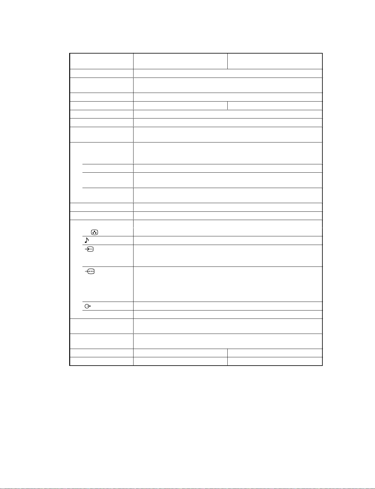
SPECIFICATIONS
Projection system
Picture tube
Projection lenses
Screen size
Television system
Color system
Stereo/Bilingual
system
Channel coverage
B/G
I
D/K
M
8(Antenna)
Audio output (Speaker)
Number of terminal
(Video)
(Audio)
(S Video)
(Component
Video)
i (Headphones)
Power requirements
Power consumption (W)
Dimensions (w/h/d, mm)
Mass (kg)
KP-ER53M90/KP-ER53M91
KP-ER53M61/KP-ER53M31
3 picture tubes, 3 lenses, horizontal inline system
7 inch high-brightnes monochorome tubes (6.3 raster size), with optical coupling
and liquidcooling system
High performance, large-diameter highbrid lens F1.0
53 inches 43 inches
B/G, I, D/K, M
PAL, PAL 60, SECAM, NTSC4.43, NTSC3.58
NICAM Stereo/Bilingual B/G, I;
A2 Stereo/Bilingual (German) B/G
VHF : E2 to E12 / UHF : E21 to E69 / CATV : S01 to
S03, S1 to S41
UHF : B21 to B68 / CATV : S01 to S03, S1 to S41
VHF : C1 to C12, R1 to R12 / UHF : C13 to C57, R21
to R60 / CATV : S01 to S03, S1 to S41, Z1 to Z39
VHF : A2 to A13 / UHF : A14 to A79/
CATV : A-8 to A-2, A to W+4, W+6 to W+84
75-ohm external terminal
15W + 15W (10% distortion)
Input: 4 Output: 1 Phono jacks; 1 Vp-p, 75 ohms
Input: 4 Output: 1 Phono jacks; 500 mVrms
Input: 2 Y: 1 Vp-p, 75 ohms,
unbalanced, sync negative
C: 0.286 Vp-p, 75 ohms
Input: 1 Phono jacks
Y: 1 Vp-p, 75 ohms, sync negative
C
B
/B-Y: 0.7 Vp-p, 75 ohms
C
R
/R-Y: 0.7 Vp-p, 75 ohms
Audio: 500 mVrms
Output: 1 Phono jack; 500 mVrms
Output: 1 Stereo minijack
110 V – 240 V (KP-ER53M91/KP-ER43M91/KP-ER53M61/KP-ER43M61)
220 V – 240 V (KP-ER53M90/KP-ER43M90/KP-ER53M31/KP-ER43M31)
270 W (KP-ER53M91/KP-ER43M91/KP-ER53M61/KP-ER43M61)
255 W (KP-ER53M90/KP-ER43M90/KP-ER53M31/KP-ER43M31)
1180 × 1427 × 623 966 × 1074 × 505
79 60
KP-ER43M90/KP-ER43M91
KP-ER43M61/KP-ER43M31
Design and specifications are subject to change without notice.
CAUTION
SHORT CIRCUIT THE ANODE OF HTE PICTURE TUBE
AND THE ANODE CAP TO THE METAL CHASSIS, CRT
SHIELD, OR CARBON PAINTED ON THE CRT, AFTER
REMOVING THE ANODE.
SAFETY-RELATED COMPONENT WARNING!!
COMPONENTS IDENTIFIED BY SHADING AND MARK
! ON THE SCHEMATIC DIAGRAMS, EXPLODED
VIEWS AND IN THE PARTS LIST ARE CRITICAL TO
SAFE OPERATION. REPLACE THESE COMPONENTS
WITH SONY PARTS WHOSE PART NUMBERS APPEAR AS SHOWN IN THIS MANUAL OR IN SUPPLEMENTS PUBLISHED BY SONY.
– 2 –

TABLE OF CONTENTS
1. SELF DIAGNOSIS FUNCTION
1-1. Diagnostic Test Indicators ................................. 5
1-2. Display of STANDBY/TIMER
Light Flash Count............................................... 6
1-3. Stopping the STANDBY/TIMER Flash ............ 6
1-4. Self-Diagnostic Screen Display ......................... 7
1-5. Handling of Self-Diagnostic
Screen Display.................................................... 7
1-6. Self-Diagnostic Circuit ...................................... 8
2. DISASSEMBLY
2-1. Rear Board Removal ......................................... 9
2-2. Main Bracket Block Removal ........................... 9
2-3. Service Position ................................................. 10
2-4. H1, H2 Boards and Resistor (Focus Pack)
Removal ............................................................. 10
2-5. Main Bracket Removal ..................................... 11
2-6. Chissis Block Removal ..................................... 11
2-7. Terminal Board Removal ................................... 12
2-8. BD, DS and D Boards Removal ........................ 12
2-9. G and G1 Board Removal .................................. 13
2-10. J1, B3, E and M1 Boards Removal .................... 13
2-11. A1 Board Removal ............................................. 14
2-12. High-Voltage Cable Installation and Removal.. 14
2-13. Mechaseal ........................................................... 14
3. SET-UP ADJUSTMENTS
3-1. Screen Voltage Adjustment
(Rough Alignment) ........................................... 15
3-2. Screen (G2) Adjustment .................................... 15
3-3. Focus Rough Adjustment .................................. 15
2-4. Deflection Yoke Tilt Adjustment ...................... 15
3-5. 2-Pole Magnet Adjustment ................................ 16
3-6. 4-Pole Magnet Adjustment ................................ 16
3-7. Green, Red and Blue Focus Adjustment
3-7-1. Green, Red and Blue Lens Focus
Adjustment .................................................... 16
3-7-2. Green, Red and Blue Electrical Focus
Adjustment .................................................... 16
KP-ER43M31/M61/M90/M91, ER53M31/M61/M90/M91
RM-961
Section Title PageSection Title Page
5. ELECTRICAL ADJUSTMENTS
5-1. Adjustments with Commander
5-1-1. How to Select Each Mode ............................. 18
5-1-2. How to Enter Service Mode .......................... 19
5-1-3. Method of Cancellation
from Service Mode ........................................ 19
5-1-4. How to Adjustments ...................................... 19
5-1-5. How to Write the Data ................................... 19
5-1-6. Memory Write Confirmation Method ........... 19
5-2. Service List ......................................................... 20
5-3. Picture Quality Adjustment
5-3-1. Preparation ..................................................... 34
5-3-2. NTSC Video Input ......................................... 34
5-3-3. NTSC RF Input .............................................. 35
5-3-4. PAL Video Input ............................................ 35
5-3-5. PAL RF Input ................................................. 36
5-4. Color Offset (53, 61 inch model only)
5-4-1. 50 Hz (PAL) TV Mode .................................. 36
5-4-2. 50 Hz (PAL) Video Mode ............................. 36
5-4-3. 60 Hz (NTSC) TV Mode ............................... 36
5-4-4. 60 Hz (NTSC) Video Mode........................... 36
5-5. Registration Adjustment
5-5-1. Setup for Adjustment ..................................... 37
5-5-2. Method of Main Deflection Adjustment ....... 37
5-5-3. Operation Method
for Projector Engine (PJE) Mode .................. 38
5-5-4. Method of Projector Engine Adjustment
(Sub Deflection Adjustment)......................... 39
5-5-5. Deflection Adjustment ................................... 41
5-6. Auto Convergence Setting ................................. 47
5-7. White Balance Adjustment ................................ 47
5-8. Auto Convergence Error Code List ................... 48
4. SAFETY RELATED ADJUSTMENT
4-1. HV Hold-Down Adjustment ............................. 17
– 3 –

KP-ER43M31/M61/M90/M91, ER53M31/M61/M90/M91
Section Title Page
6. DIAGRAMS
6-1. Block Diagrams .................................................. 49
6-2. Frame Schematic Diagram ................................. 62
6-3. Circuit Boards Location ..................................... 63
6-4. Schematic Diagrams........................................... 63
6-5. Printed Wiring Boards........................................ 97
6-6. Wave Forms ....................................................... 110
6-7. IC Block Diagrams ............................................. 117
6-8. Semiconductors .................................................. 119
7. EXPLODED VIEWS
7-1. Screen and Cover Block (KP-ER43) ................ 122
7-2. Screen and Cover Block (KP-ER53) ................ 123
7-3. Cabinet and Panel Block (KP-ER43) ............... 124
7-4. Cabinet and Panel Block (KP-ER53) ............... 125
7-5. Main Bracket Block ........................................... 126
7-6. Picture Tube Block............................................. 127
RM-961
8. ELECTRICAL PARTS LIST ............................ 128
– 4 –
KP-ER43M31/M61/M90/M91, ER53M31/M61/M90/M91
SECTION 1
SELF DIAGNOSIS FUNCTION
The unit in this manual contain a self-diagnostic function. If an error occurs, the STANDBY/TIMER lamp will automatically begin to
flash.
The number of times the lamp flashes translates to a probable source of the problem. A definition of the STANDBY/TIMER lamp flash
indicators is listed in the instruction manual for the user's knowledge and reference. If an error symptom cannot be reproduced, the
remote commander can be used to review the failure occurrence data stored in memory to reveal past problems and how often these
problems occur.
1-1. DIAGNOSTIC TEST INDICATORS
When an errors occurs, the STANDBY/TIMER lamp will flash a set number of times to indicate the possible cause of the problem. If
there is more than one error, the lamp will identify the first of the problem areas.
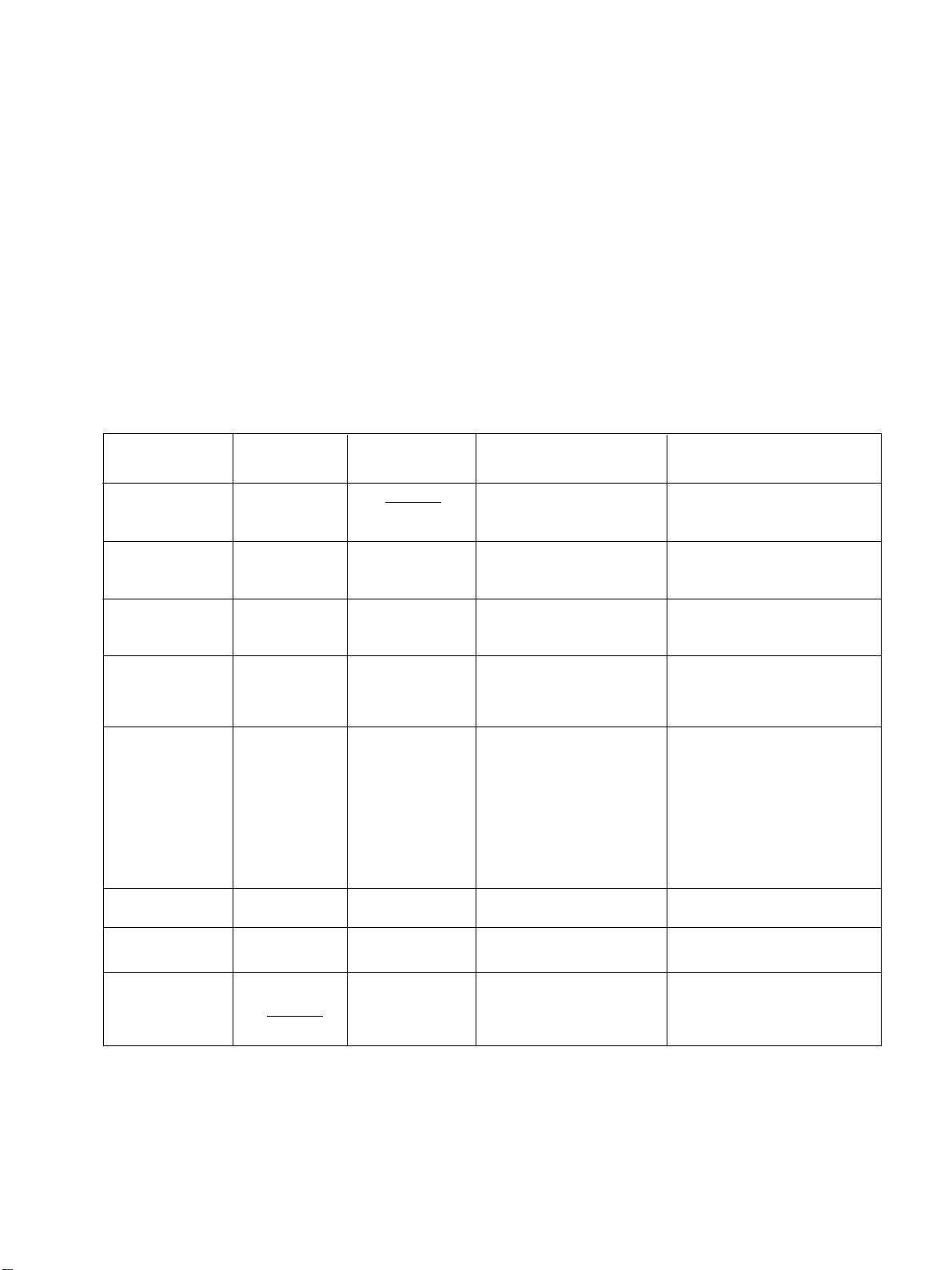
Result for all of the following diagnostic items are displayed on screen. No error has occurred if the screen displays a “0”.
Diagnostic
Item
Description
No. of times
STANDBY/TIMER
lamp flashes
Self-diagnostic
display/
Diagnostic result
Probable Cause Location
Detected Symptoms
RM-961
•Power does not
turn on
•+B overcurrent
(OCP)
•+B overvoltage
(OVP)
•Vertical deflection
failure
•White balance
failure
(no PICTURE)
•High Voltage
failure
•Audio Protection
Does not light
2 times
3 times
4 times
5 times
6 times
7 times
002:000 or
002:001 ~ 255
003:000 or
003:001 ~ 255
004:000 or
004:001 ~ 255
005:000 or
005:001 ~ 255
006:000 or
006:001 ~ 255
007:000 or
007:001 ~ 255
•Power cord is not plugged in.
•Fuse (F6001) is burned out.
(G, G1 board)
•H. OUT Q5104 is shorted.
•H. LIN Q5105 is shorted.
(D board)
•IC6002 faulty.
•10.5 V is not supplied.
(G, G1 board)
•V. OUT IC5302 faulty.
•R5340 open
•R5341 open
(D board)
•G2 is improperly adjusted.
(Note 1)
•CRT problem.
•Video OUT IC7101 (CR
board), IC7201 (CG board),
IC7301 (CB board) are faulty.
•IC8306 (J1 board) and
IC4301 (E board) are faulty.
•No connection E board to CR
board.
•IC6301 (G, G1 bard) faulty.
•Power supply fails.
•IC1101 (A1 board) faulty.
•Power does not come on.
•No power is supplied to the PJ.
•AC power supply is faulty.
•Power does not come on.
•Load on power line is shorted.
•Power does not come on.
•Vertical deflection pulse is
stopped.
•Vertical size is too small.
•Vertical deflection stopped.
•No raster is generated.
•CRT cathode current detection
reference pulse output is small.
•+135 V is too high.
•There is picture but speaker
does not release sound.
•Micro reset
Note 1 : Refer to screen (G2) adjustment in section 4-2 of this manual.
101:000 or
101:001 ~ 255
•Discharge CRT
(CR, CG, CB boards)
•Static discharge
•External noise
– 5 –
•Power is shut down shortly,
after this return back to normal.
•Detect Micro latch up.
KP-ER43M31/M61/M90/M91, ER53M31/M61/M90/M91
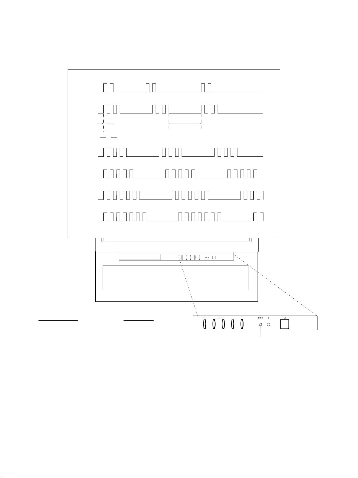
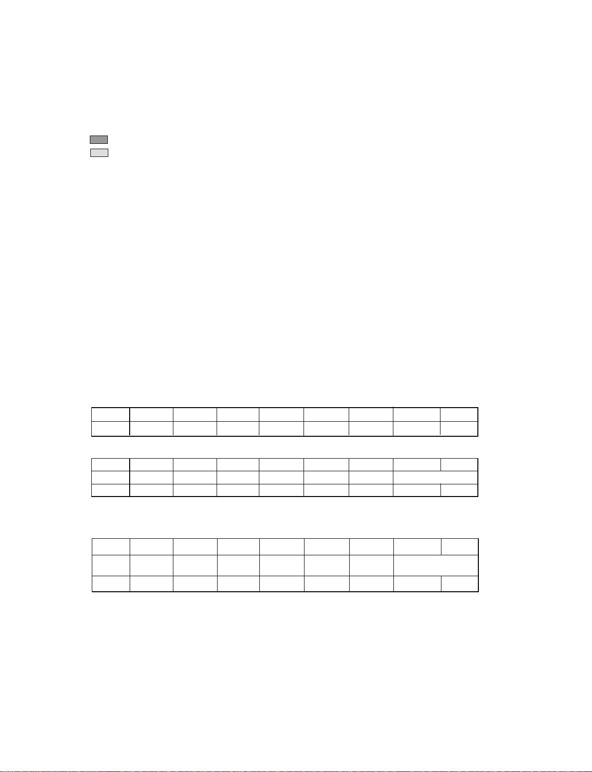
1-2. DISPLAY OF STANDBY/TIMER LIGHT FLASH COUNT
2 times
3 times
Lamp ON
0.3 sec.
Lamp OFF
0.3 sec.
4 times
5 times
Lamp OFF
3 sec.
RM-961
6 times
7 times
Diagnostic Item Flash Count *
+B overcurrent 2 times
+B overvoltage 3 times
V deflection stop 4 times
White balance failure 5 times
High voltage protector 6 times
Audio Protection 7 times
PROGR
STANDBY/TIMER
lamp
* One flash count is not used for self-diagnostic.
1-3. STOPPING THE STANDBY/TIMER FLASH
Turn off the power switch on the TV main unit or unplug the power cord from the outlet to stop the STANDBY/TIMER lamp from
flashing.
– 6 –
KP-ER43M31/M61/M90/M91, ER53M31/M61/M90/M91
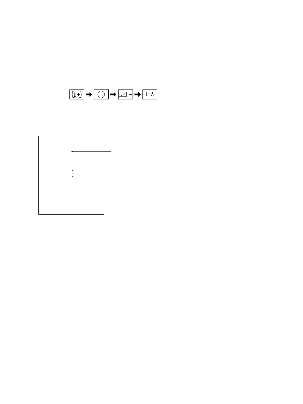
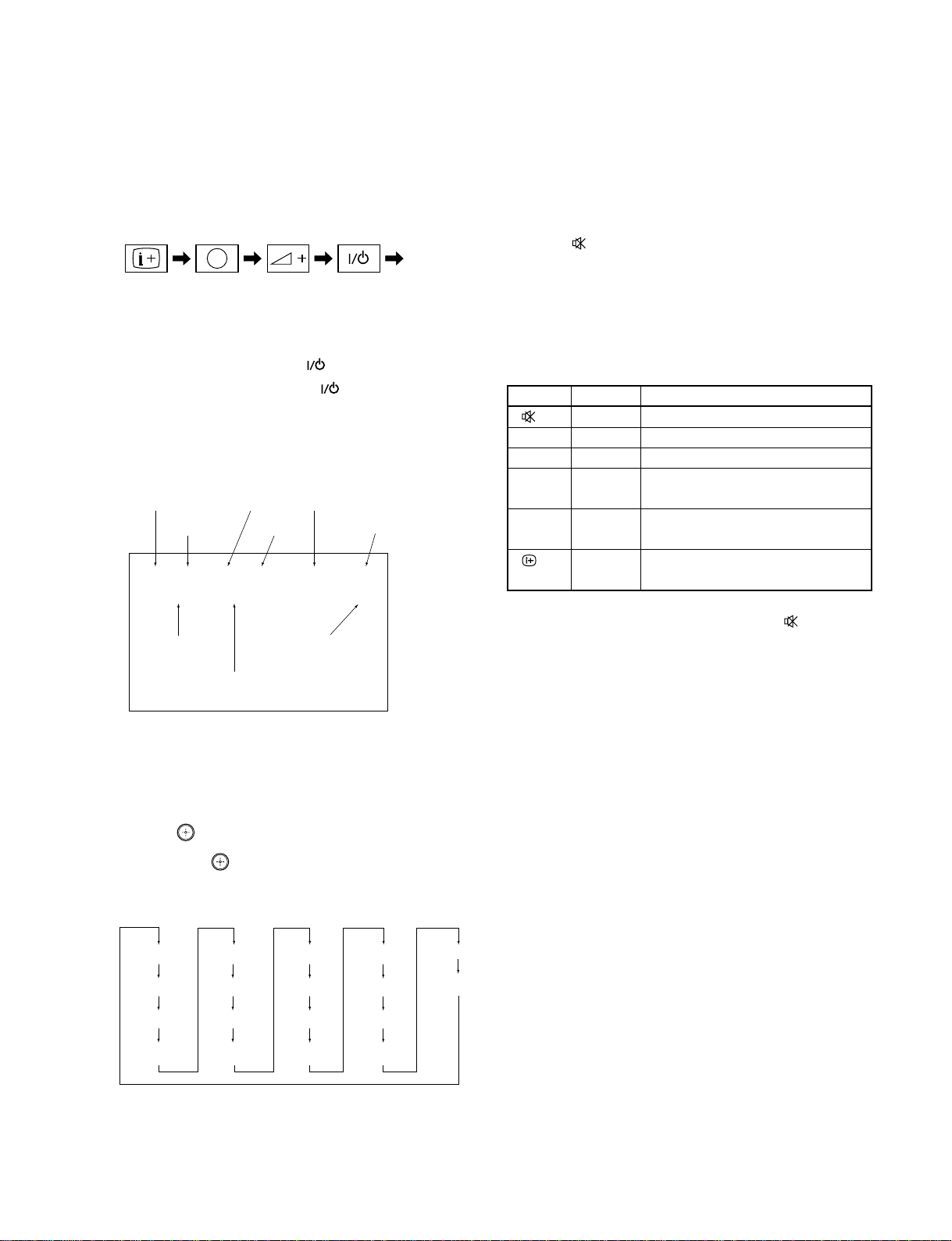
1-4. SELF-DIAGNOSTIC SCREEN DISPLAY
For errors with symptoms such as “power sometimes shuts off” or “screen sometimes goes out” that cannot be confirmed, it is possible
to bring up past occurrences of failure for confirmation on the screen:
[To Bring Up Screen Test]
In standby mode, press buttons on the remote commander sequentially in rapid succession as shown below:
5
RM-961
(
DISPLAY
(DIGIT 5) (VOLUME –) (POWER)ON SCREEN
)
*
* : Note that this differs from entering the service mode (volume +)
Self-Diagnosis screen display
SELF DIAGNOSTIC
002:000
Numeral “0” means that no fault has been detected.
003:000
004:000
005:001
006:002
Numeral “1” means a fault has been detected.
Numeral “2” means two faults have been detected.
007:000
101:000
1-5. HANDLING OF SELF-DIAGNOSTIC SCREEN DISPLAY
Since the diagnostic results displayed on the screen are not automatically cleared, always check the self-diagnostic screen
during repairs. When you have completed the repairs, clear the result display to “0”.
Unless the result display is cleared to “0”, the self-diagnostic function will not be able to detect subsequent faults after completion of
the repairs.
[Clearing the result display]
To clear the result display to “0”, press button on the remote commander sequentially as shown below when the diagnostic screen is
being displayed.
Press “8” button
(It will indicate “CLEAR” on the screen.)
,
(The “CLEAR” display change to red color.)
Press “-” button
[Quitting Self-diagnostic screen]
To quit the entire self-diagnostic screen, turn off the power switch on the remote commander or the main unit.
– 7 –
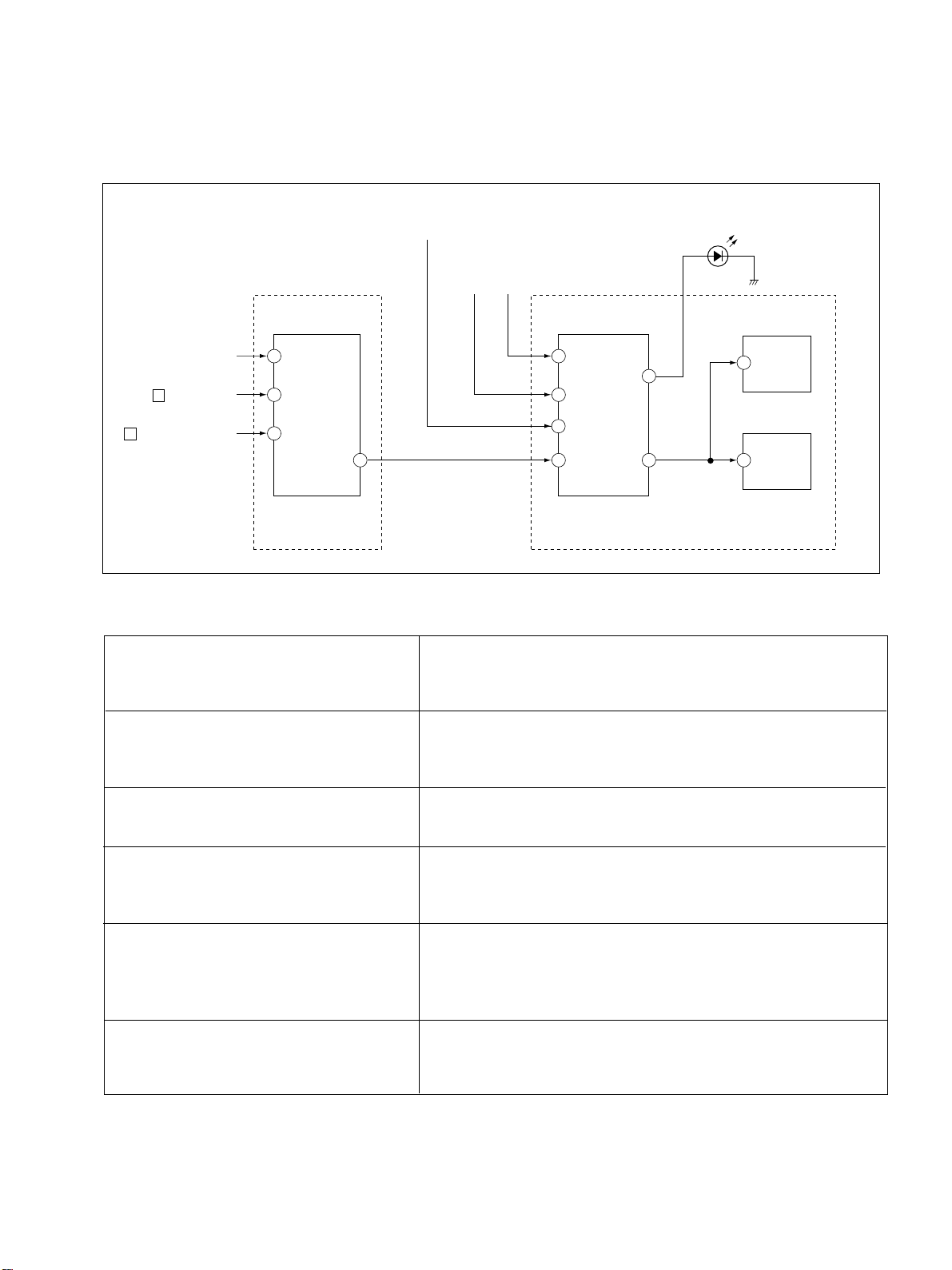
1-6. SELF-DIAGNOSTIC CIRCUIT
IC4301
Y/C JUNGLE
From Q1203
(A1 board)
KP-ER43M31/M61/M90/M91, ER53M31/M61/M90/M91
From G,G1 board
OCP
OVP
IC002
SYSTEM
To H1 board
IC004
MEMORY
RM-961
25 IKINFrom CRT (IK)
H
(D board)
V
(D board)
20 XRAYFrom IC5201
16 V PROTFrom D5303/D5704
SDA 61 48 SDA0 SDA1 SDA47 5
3 OCP
6 OVP
APROT
57
LED1 54
SDA5
IC006
MEMORY
CXA2100Q CXP750096
M1 boardE board
+B overcurrent (OCP) Occurs when an overcurrent on the +B (135 V) line is detected by Q6303.
If Q6303 go to ON, the voltage to pin 3 of IC002 go to UP. The unit will
automatically turn off.
+B overvoltage (OVP) Occurs when an overvoltage on the +B (135 V) line is detected by D6318.
If D6318 go to ON, then voltage to pin 6 of IC002 go to UP. The unit will
automatically turn off.
Vertical deflection failure Occurs when an absence of the vertical deflection pulse is detected by
Q5302, Q5303, and D5303. Shut down the power supply.
White balance failure If the RGB levels do not balance or become low level within 5 seconds. This
error will be detected by IC4301.
TV will stay on, but there will be no picture.
High voltage protector of Horizontal Deflection Occurs when an overvoltage of horizontal pulse is detected by D5115 and
IC5201.
If the voltage of pin 1 of IC5201 goes to High, the voltage to pin 20 of IC4301
go to UP. The unit will automatically turn off.
Audio Protector If the Audio out lines become DC.This error will be detected by Q1202,
Q1204 and Q1203.
The unit will automatically turn off.
– 8 –
KP-ER43M31/M61/M90/M91, ER53M31/M61/M90/M91
SECTION 2
DISASSEMBLY
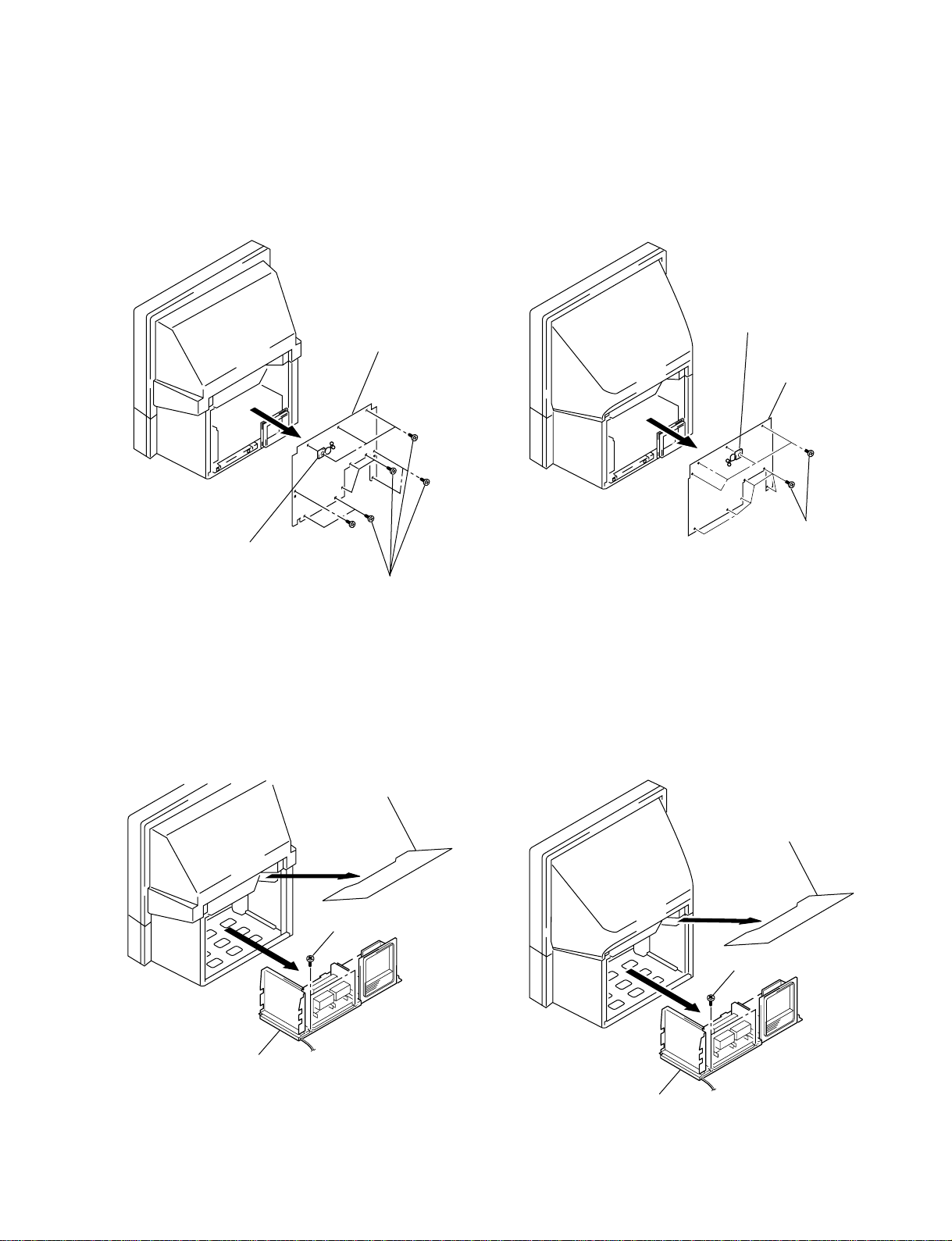
2-1. REAR BOARD REMOVAL
(1) KP-ER43 (2) KP-ER53
2 Rear board
RM-961
3 Purse lock
2 Rear board
3 Purse lock
1 Thirteen screws
(BVTP4 X16)
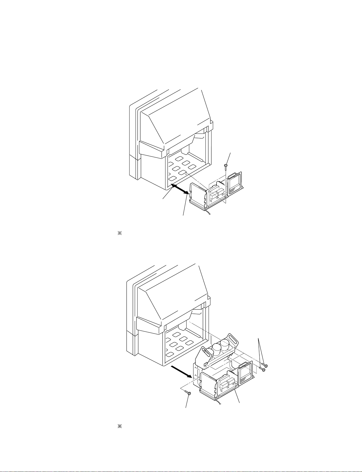
2-2. MAIN BRACKET BLOCK REMOVAL
(1) KP-ER43 (2) KP-ER53
1 Light shield block
2 Two screws
(Hexagon head)
1 Thirteen screws
(BVTP4 X16)
1 Light shield block
2 Two screws
(Hexagon head)
3 Main bracket block
3 Main bracket block
– 9 –
KP-ER43M31/M61/M90/M91, ER53M31/M61/M90/M91
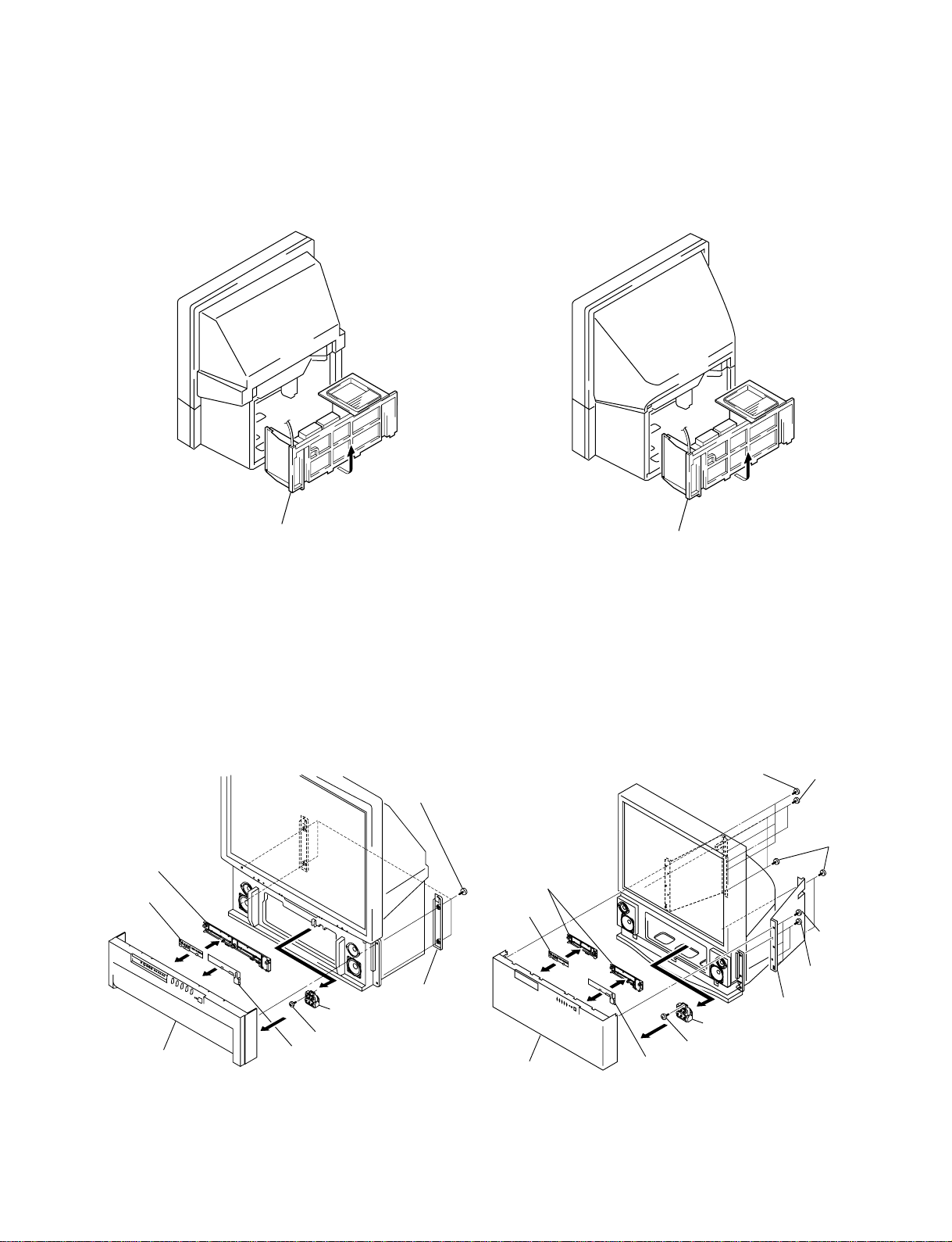
2-3. SERVICE POSITION
(1) KP-ER43 (2) KP-ER53
RM-961
Main bracket block Main bracket block
2-4. H1, H2 BOARDS AND RESISTOR (FOCUS PACK) REMOVAL
(1) KP-ER43 (2) KP-ER53
1 Four screws
(Hexagon head)
4Bracket (H)
6Bracket (H)
5H2 board
3 Speaker grille
2 Grille cover
8Resistor
(Focus pack)
7Screw (BVTP4 X16)
6H1 board
7H2 board
5 Speaker grille
8H1 board
1 Three screws
(BVTP4 X16)
q;Resister
(Focus pack)
9Screw (BVTP4 X16)
2 Two screws
(Hexagon head)
3 Four screws
(Hexagon head)
1 Three screws
(BVTP4 X16)
2 Two screws
(Hexagon head)
4 Grille cover
– 10 –
2-5. MAIN BRACKET REMOVAL
KP-ER43M31/M61/M90/M91, ER53M31/M61/M90/M91
RM-961
1 Two screws
(Hexagon head)
3 Set the main bracket.
Pay particular attention to the wires of each printed circuit boards when puling out the main bracket.
2-6. CHASSIS BLOCK REMOVAL
2 Pull the main braket, and remove each connectors on main bracket.
1 Four screws
(Hexagon head)
1 Two screws
(Hexagon head)
Pull out the chassis block by gripping the handles as shown in the diagram.
At this time, pay particular attention to the components removed in (1).
2 Pull out the chassis block.
– 11 –
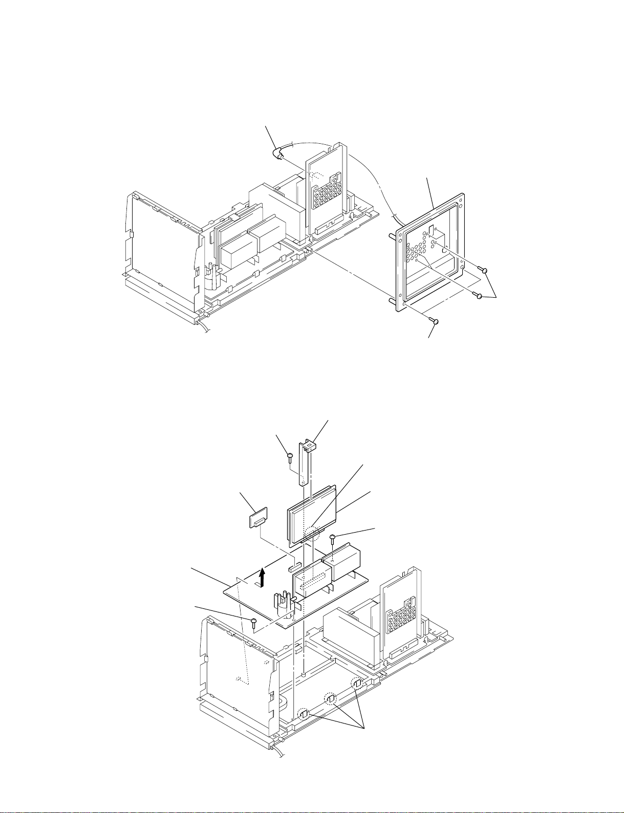
2-7. TERMINAL BOARD REMOVAL
3 RF cable
KP-ER43M31/M61/M90/M91, ER53M31/M61/M90/M91
RM-961
4 Terminal board
1 Five screws
( + BVTP 3 X 12)
2-8. BD, DS AND D BOARDS REMOVAL
1 Screw
( +BVTP 3X12)
5 DS board
8 D board
6 Screw
( +BVTP 3X12)
2 Two screws
( + BVTP 4 X 16)
2 BD holder
3 claw
4 BD board
6 Screw
( +BVTP 3X12)
– 12 –
7 Three claws
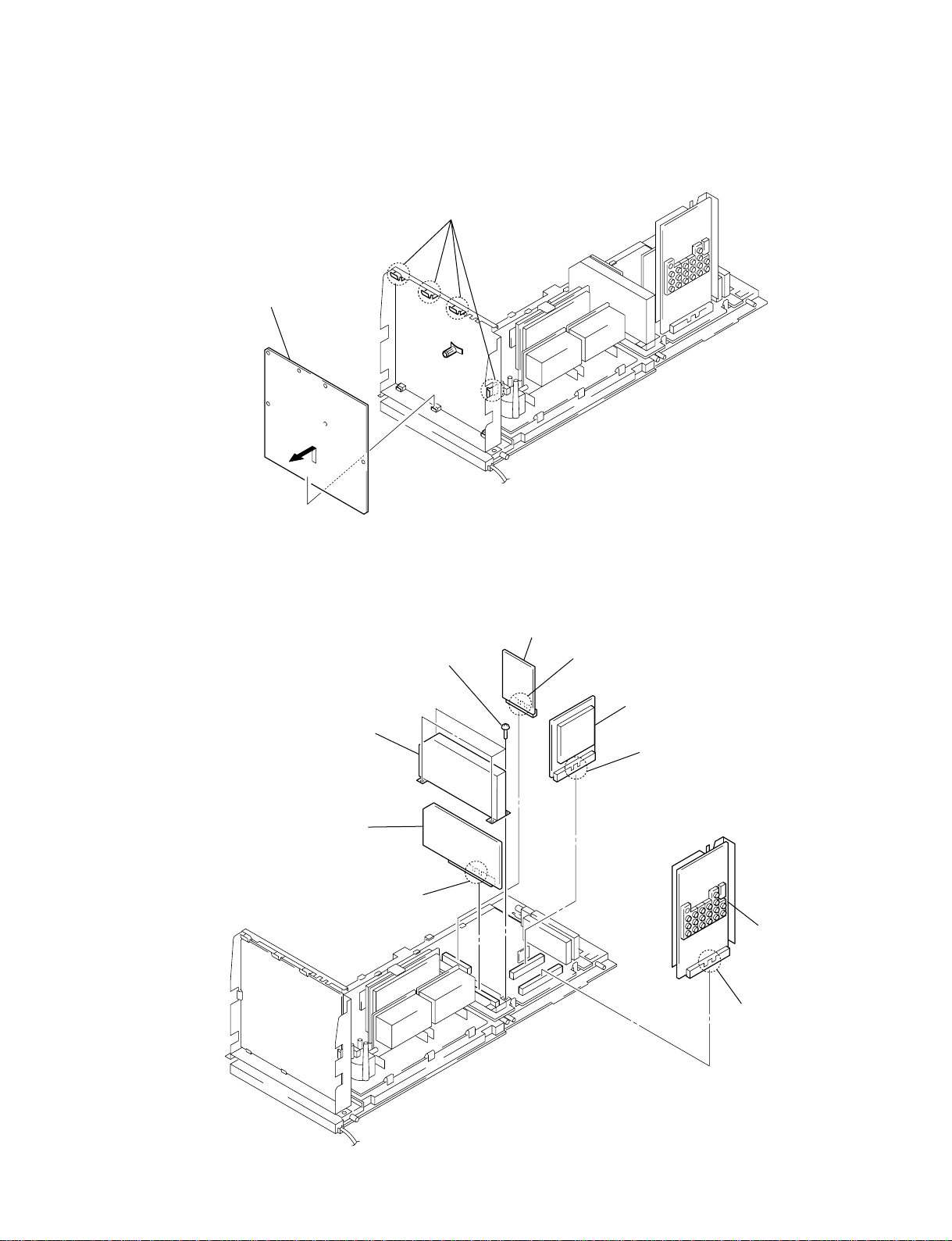
2-9. G AND G1 BOARD REMOVAL
KP-ER43M31/M61/M90/M91, ER53M31/M61/M90/M91
RM-961
2 G board
(KP-ER43M30/ER43M91,
KP-ER53M30/ER53M91)
G1 board
(KP-ER43M61/ER43M90,
KP-ER53M61/ER53M90)
1 Four claws
2-10. J1, B3, E AND M1 BOARDS REMOVAL
7 Four serews
( + BVTP 3 X 12)
6 E board
5 claw
8 Shield case
0 B3 board
4 M1 board
3 claw
9 claw
2 J1 board
1 claw
– 13 –
KP-ER43M31/M61/M90/M91, ER53M31/M61/M90/M91
RM-961
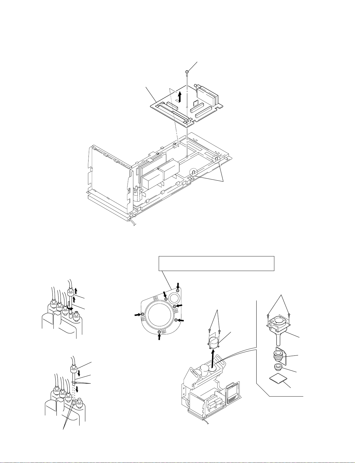
2-11. A1 BOARD REMOVAL
1 Screw
( +BVTP3 X12)
3 A1 board
2 Two claws
2-12. HIGH-VOLTAGE CABLE
INSTALLATION AND REMOVAL
(1) Remover
1 Rubber cap
2 HV cable turn 90°
(2) Installation
2 Rubber cap
1 HV cable
Hook
2-13. MECHASEAL
Removing the arrow-marked screw is strictly inhibited.
If removed, it may cause liquid spill.
6 Four screws
( +BVTP4 X16)
1 Four screws
( +BVTP4 X16)
2 Lens
7 Picture tube
5 Deflection yoke
4 Neck assembly
3 CR board
Gutter
– 14 –
KP-ER43M31/M61/M90/M91, ER53M31/M61/M90/M91
Scanning line visible.
SECTION 3
SET-UP ADJUSTMENTS
RM-961
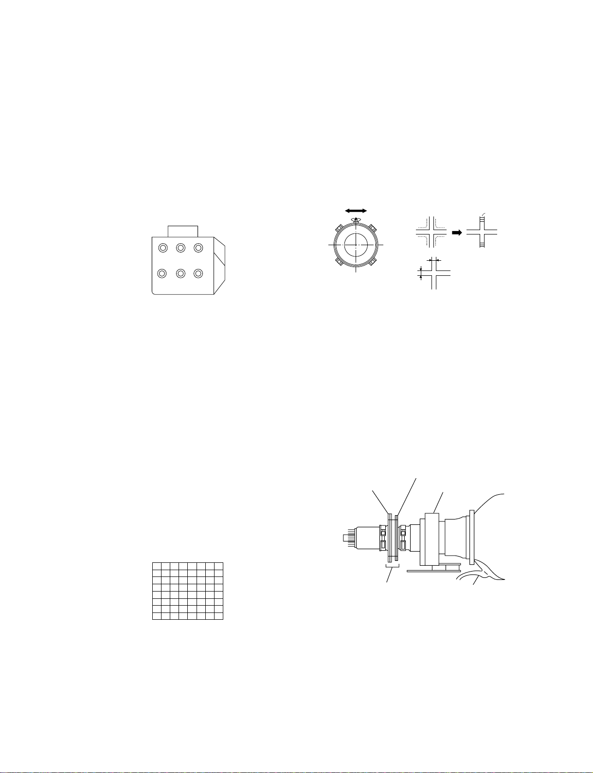
3-1. SCREEN VOLTAGE ADJUSTMENT
(ROUGH ALIGNMENT)
1. Receive the Monoscope signal.
2. Set 50% BRIGHTNESS and minimum PICTURE.
3. Turn the red VR on the focus pack all the way to the left and
then gradually turn it to the right until the point where you
can see the retrace line.
4. Next gradually turn it to the left to the position where the
retrace line disappears.
RG
RG
B
SCREEN
B
FOCUS
Focus Pack
Fig. 3-1
3-2. SCREEN (G2) ADJUSTMENT
1. Turn on the power of the set.
2. Select VIDEO1 mode without signals.
3. Supply DC 175 ±0.5 V from external power supply to
TP7103 (KR), TP7203 (KG) or TP7303 (KB) of CR board,
CG board and CB board.
3. Adjust red, green and blue screen voltage to until retrace
line disappears with screen VR on the focus pack.
3-3. FOCUS ROUGH ADJUSTMENT
1. Loose the lens screw.
2. Set in the service mode. (Refer to SECTION 5.)
3. Place the caps on the red and blue lens so that only the green
color is shown.
4. Press “1 ” or “4” button on the commander and select
“PJE”, press “6” three times on the Commander to display
the test signal (crosshatch) on the screen.
5. Rotate the green lens and align to obtain the best lens focus
at the center area.
6. Rotate the green focus VR on the focus pack and align to
obtain the best electrical focus in the top right corner.
7. Perform the same alignment for red and blue lenses and electric focus.
8. Fix lens screw.
A
Minimize both A and B.
Lens
Fig. 3-3
B
Fig. 3-4
3-4. DEFLECTION YOKE TILT ADJUSTMENT
1. Receive the Monoscope signal.
2. Place the caps on the red and blue lens so that only the green
color.
3. Loosen the deflection yoke setscrew and align the tilt of the
Deflection yoke so that the bars at the center of the
monoscope pattern are horizontal.
4. After aligning the deflection yoke, fasten it securely to the
funnel-shaped portion (neck) of the CRT.
5. The tilt of the deflection yoke for red and blue is aligned the
same as was done for green.
4-pole magnet
2-pole magnet
Deflection yoke
Test signal
Fig. 3-2
– 15 –
Neck Assy
Anode cap
Make sure deflection yoke is
touching CRT closely.
Fig. 3-5
KP-ER43M31/M61/M90/M91, ER53M31/M61/M90/M91
RM-961
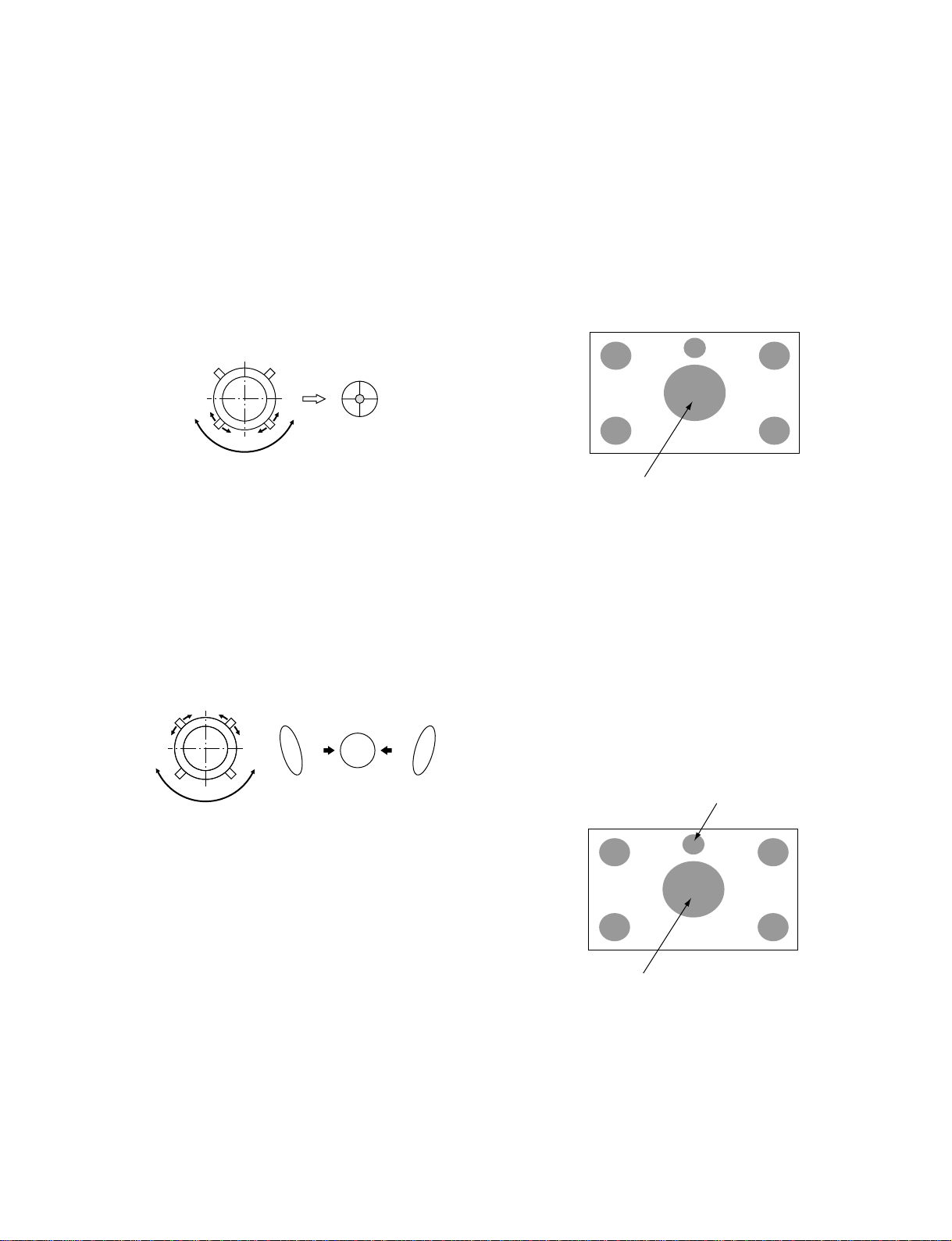
3-5. 2-POLE MAGNET ADJUSTMENT
1. Receive the Dot signal.
2. Place the caps on the red and blue lens so that only the green
color is shown.
3. Turn the green focus VR on the focus pack to the right and
set to over focus to enlarge the spot.
4. Now align the 2-Pole Magnet so that the enlarged spot is in
the center of the just focus spot.
(center of the dot doesn't move)
5. Align the green focus VR and set for just (precise) focus.
6. Perform the same alignment for red and blue.
Use the center dot
Fig. 3-6
3-6. 4-POLE MAGNET ADJUSTMENT
1. Receive the Dot signal.
2. Place the caps on the red and blue lens so that only the green
color is shown.
3. Turn the green focus VR on the focus pack to the left and set
to under focus to enlarge the spot.
4. Now align the 4-Pole Magnet so that the enlarged spot becomes a perfect circle.
5. Perform the same alignment for red and blue.
Use the center dot
OKNG NG
3-7. GREEN, RED AND BLUE FOCUS
ADJUSTMENT
3-7-1. Green, Red and Blue Lens Focus Adjustment
1. Receive the Monoscope signal.
2. Place the caps on the red and blue lens so that only the green
color is shown.
3. Rotate the green lens and adjust to obtain the best lens focus
at the center area.
4. Fix lens screw.
5. Repeat above process for red and blue.
Adjust Point
Fig. 3-8
3-7-2. Green, Red and Blue Electrical Focus
Adjustment
1. Receive the Monoscope signal.
2. Place the caps on the red and blue lens so that only the green
color is shown.
3. Rotate the green focus VR on the focus pack and adjust to
obtain the best electrical focus in the adjust point.
4. Repeat above process for red and blue.
5. Repeat adjustment items 3-3. FOCUS ROUGH ADJUSTMENT, 3-5. 2-POLE MAGNET ADJUSTMENT, 3-6. 4POLE MAGNET ADJUSTMENT and 3-7. GREEN, RED
AND BLUE FOCUS ADJUSTMENT, and adjust to obtain
the best focus.
Fig. 3-7
Adjust Point of Blue
Adjust Point of Green and Red
Fig. 3-9
– 16 –
KP-ER43M31/M61/M90/M91, ER53M31/M61/M90/M91
CN5003
R9901
SECTION 4
SAFETY RELATED ADJUSTMENT
RM-961
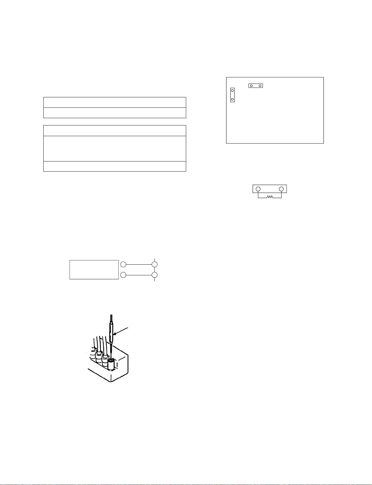
When replacing the following components marked with ] on
the schematic diagram, always check hold-down voltage and
if necessary re-adjust.
Part Replaced ([)
R9901
Part Replaced (])
D Board C5117, C5123, C5127, C5143, D5115,
D5204, Q5104, R5136, R5138, R5140,
R9901, T5102, T5104, T5103 (FBT)
G Board C6024, C6032, D6020
4-1. HV HOLD-DOWN ADJUSTMENT
1. Connect HV static voltmeter to HV Block.
2. Mount a resistor (R9901 : 43 k , 1/4 W, METAL
FILM) at CN5003.
3. Remove CN5002 and connect External Power Supply to
CN5002 1 pin (+135 V) and 2 pin (GND).
4. Turn on the set.
Power
Supply
+
–
Fig. 4-1
Remove the cap off
from the unused
terminal and connect a
HV static voltmeter
there.
1
CN5002
2
D BOARD
CN5002
– CONDUCTOR SIDE –
CN5003
Fig. 4-3
Fig. 4-4
5. Receive the Dot signal and set PICTURE/BRIGHTNESS
to minimum.
6. Slowly up the supply voltage from 0 V to 135 V until
hold-down circuit works (picture disappear).
7. Read the HV static voltmeter of peak HV voltage.
Spec : 33.7 ~ 35.3 kV
8. If Hold-down voltage is less than 33.7 kV then replace
R9901 of 43 k with that of 39 k , and check if the
voltage is within the spec.
9. If hold-down voltage is over than 35.3 kV then replace
R9901 of 43 k with that of 47 k , and check if the voltage is within the spec.
Fig. 4-2
– 17 –
KP-ER43M31/M61/M90/M91, ER53M31/M61/M90/M91
SECTION 5
ELECTRICAL ADJUSTMENTS
RM-961
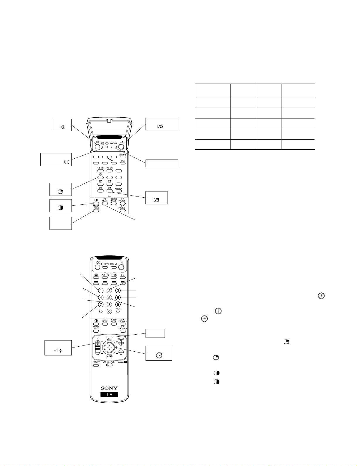
5-1. ADJUSTMENTS WITH COMMANDER
Service adjustment to this model can performed with the supplied remote commander RM-961
(open the cover)
MUTE
Write data to NVM
ON SCREEN
DISPLAY
Copy PAL data
to NTSC
PIP
TWIN
PROGR
INDEX
Adjustment item
up
Adjustment item
down
User control goes
to the standard state
Read data from
NVM
VOLUME +
.>N
xX
z
TV STANDBY
DRC-MF (blue)
SWAP
Change
the PICTUER MODE
Copy data to all
mode
Data up
Data down
Initialize data
(Not stored)
MENU
JOYSTICK
Up : Category up
Down : Category down
Push : Enter
RM-961
5-1-1.How to Select Each Mode
The adjustment requires the following modes:
50 Hz 60 Hz WIDE 60 Hz
(PAL) (NTSC) (NTSC)
DRC1250 aaa
DRC100 aa
X
PIP aaa
TWIN aa
INDEX aa
X
X
1. Selection of Mode Between 50 Hz and 60 Hz
50 Hz : Enter the PAL signal.
60 Hz : Enter the NTSC signal.
WIDE 60 Hz : Enter the NTSC signal with video input
2. Selection of DRC Mode
1) Press “DRC-MF (blue)” button on the commander, repeatedly until displays the mode that you want to select on the
screen.
Note : The DRC-MF mode is not selectable when using the
“PROGRAM INDEX” or “FAVORITE CH” feature, or
when the “GAME MODE”, “PIP”, or “TWIN” mode is
turned “ON”.
3. Selection of WIDE mode
The WIDE mode is selected only when the DRC1250 of NTSC
signal with video input mode is active.
1) Enter the NTSC signal with video input.
2) Press “DRC-MF (blue)” button on the commander to select
“DRC1250”.
3) Press “MENU” button on the commander and move “
up or down to enter the “FEATURE” b “WIDE MODE”.
4) Move “
” up or down to select “ON” or “OFF”, and push
“ (ENTER)” button.
5) Press “MENU” button to return to normal screen.
4. Selection of PIP mode
1) Open the remote control cover, press “ (PIP)” button on
the commander.
2) Press “
(PIP)” button again to return to normal screen.
5. Selection of TWIN mode
1) Press “ (TWIN)” button on the commander.
2) Press “
(TWIN)” button again to return to normal screen.
6. Selection of INDEX mode
1) Press “PROGR INDEX” button on the commander.
2) Press “PROGR INDEX” button again to return to normal
screen.
”
– 18 –
KP-ER43M31/M61/M90/M91, ER53M31/M61/M90/M91
RM-961
5-1-2. How to Enter Service Mode
1. Turn on the main power switch to place this set in standby
mode. (LED will light in red.)
2. Press the buttons on the commander as follows, and enter
service mode.
Enter the
“Service mode”
)
(
DISPLAY
5
(DIGIT 5) (VOLUME +)ON SCREEN
)
TV
(
STANDBY
5-1-3. Method of Cancellation from Service Mode
1. Set the standby mode (Press “ (TV STANDBY)” button
on the commander), then press “
(TV STANDBY)” but-
ton again, hereupon it becomes TV mode.
5-1-4. How to Adjustments
1. Set in the service mode, the following screen will appear.
Category Name Item Name Mode
Item No.
GEO 00 VSZ 2B SERVICE 50
0 025Q 1.4M 00 FF 0001
Data
50 : PAL, SECAM
60 : NTSC
5-1-5.How to Write the Data
1. Set in the service mode.
2. Press “1” or “4” button on the commander, select the adjustment item, and press “3” or “6” button to change the
data.
3. Press “ (MUTE)” button on the commander and it will
indicate “WRITE” on the screen.
4. Press “-” button on the commander to write into memory.
(The “WRITE” display will be changed to red color while
executing, and back to “SERVICE”.)
Commander Function (Except PJE mode)
Button Mode Description
+ - WRITE Writes data to NVM.
7 + - READ Reads data from NVM.
8 + - NORMAL All user control goes to the standard.
5 + - INITIAL Service data initialization. Not stored.
(Be sure not to use usually)
2 + - COPY Copies and writes data of DRC1250
(50Hz) mode to all other modes.
+ - WRT5060 Copies data of 50 Hz (PAL) mode to
60 Hz (NTSC) mode.
Suffix No.
Software
Version
Total Power On time
(Hours)
2. Press “1” or “4” button on the commander to select the
adjustment item.
3. Press “3” or “6” button on the commander to change the
adjustment data.
4. Move “
When move “
” up or down to select the adjustment category.
” up (category up), service mode changes in
the order as shown below.
GEO
DAC
WHB
SAJ
JGL
YCT
SYC
AP
MSP
LTI
MID
3CM
2CM
DSP
TXT
PJE*
OPM
OPB
Note : Before changing to other modes, press “ (MUTE)” +
“-” buttons on the commander to write the data.
(Omission of this operation causes the data to be returned
to the data before adjustment.)
: Confirm the adjustment mode before writing data for data
values because to vary in each adjustment mode.
: The adjustment item that there are no relations in the ad-
justment is not to change data values because all items are
written in each adjustment mode.
5-1-6.Memory Write Confirmation Method
1. After adjustment, pull put the plug from AC outlet, and then
plug into AC outlet again.
2. Turn the power switch ON and set in service mode.
3. Call the adjustment items again to confirm adjustments were
made.
* : When it moves from PJE to other categrys,
repeat 1 or 4 button and press it.
– 19 –
KP-ER43M31/M61/M90/M91, ER53M31/M61/M90/M91
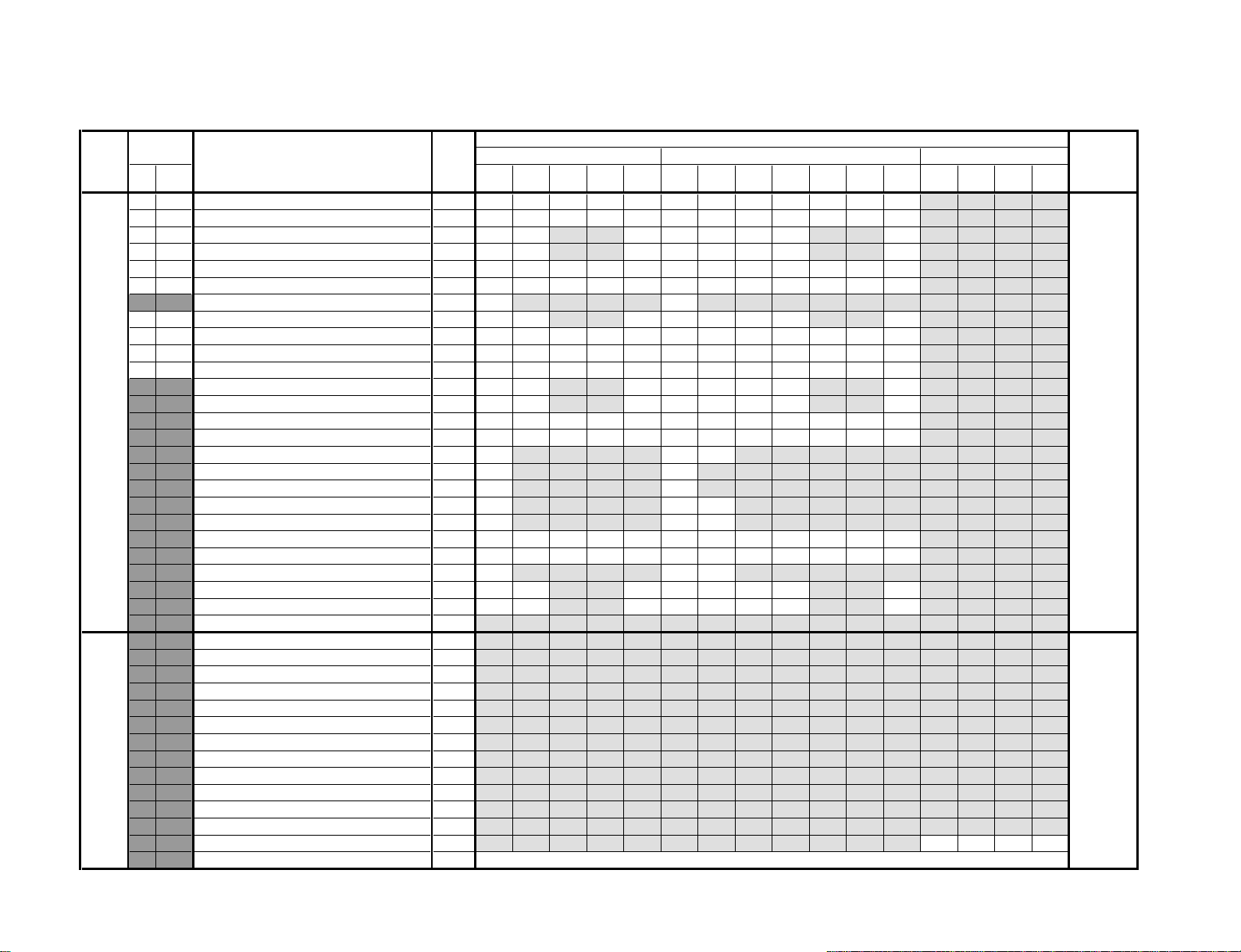
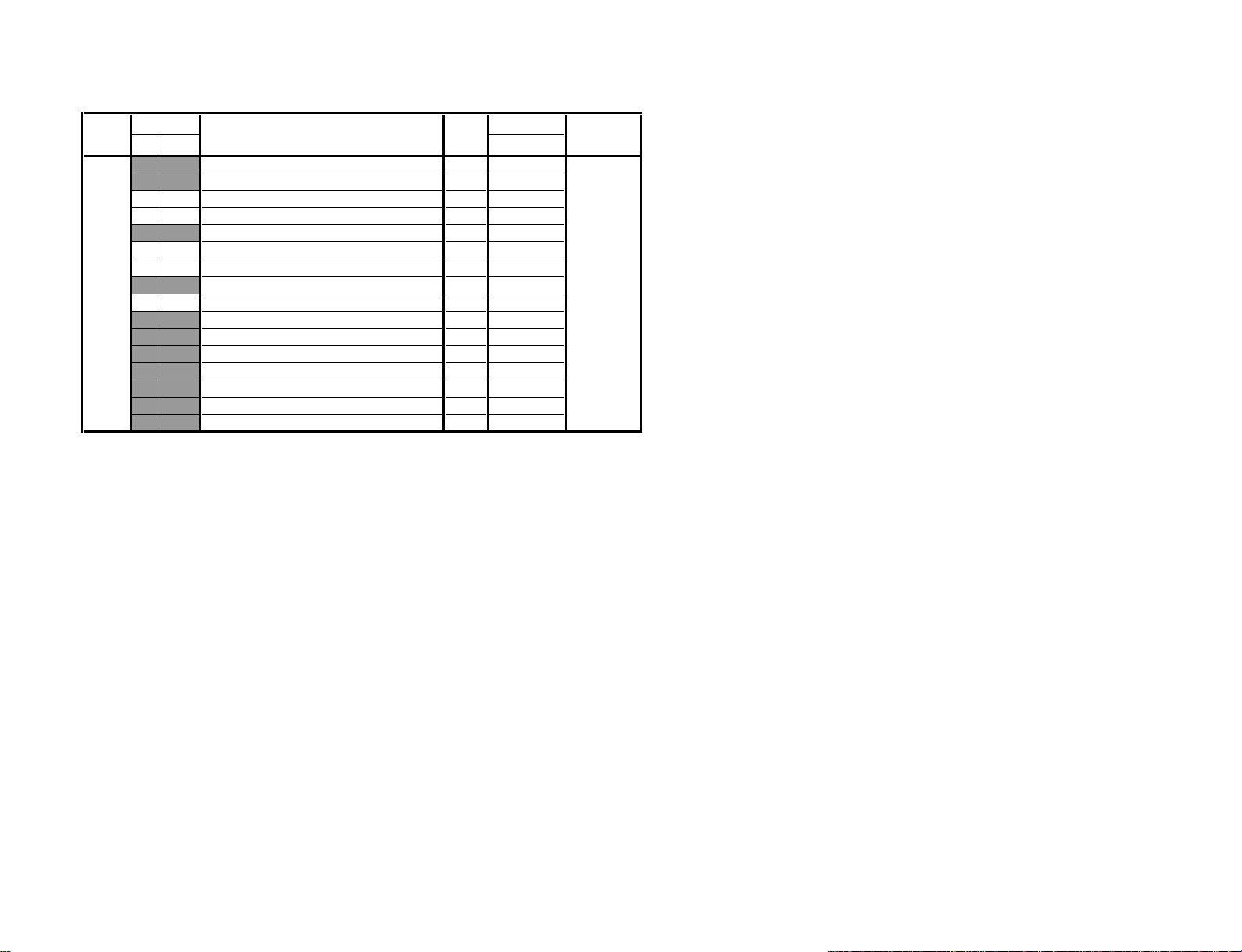
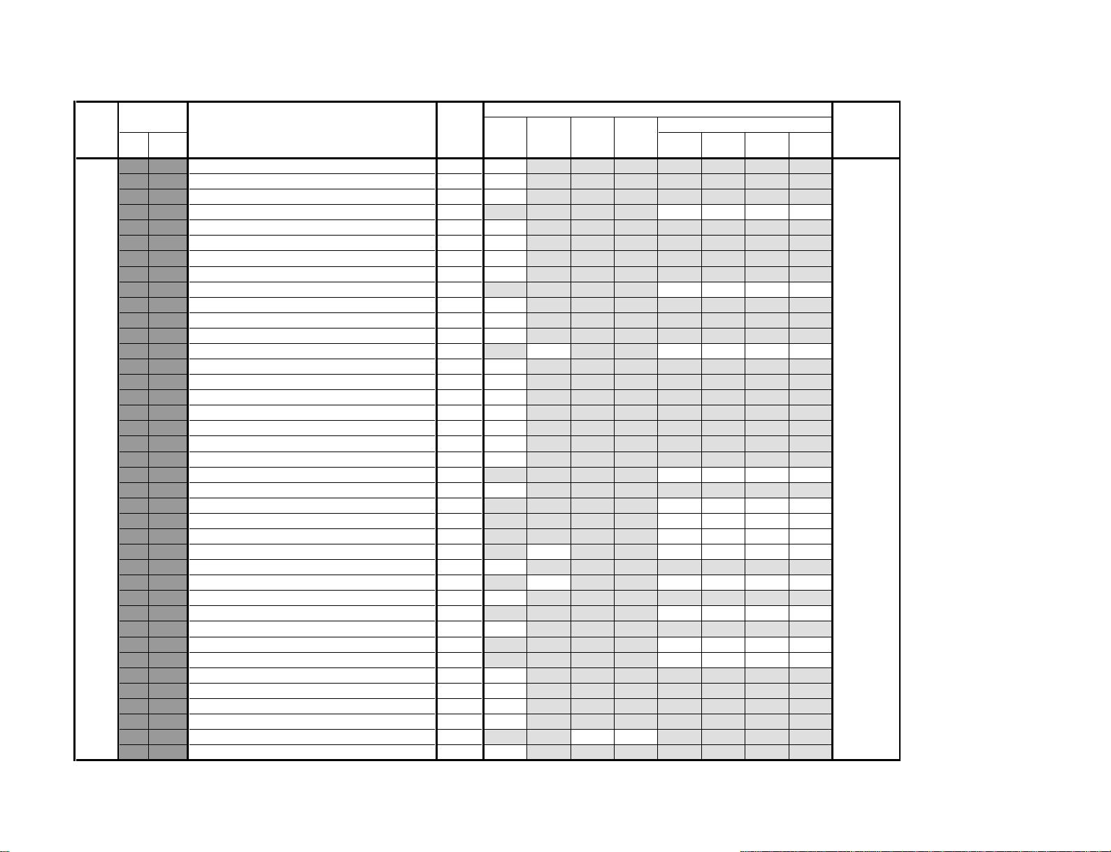
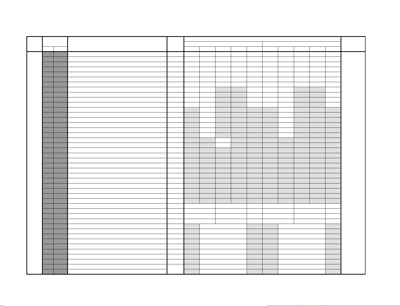
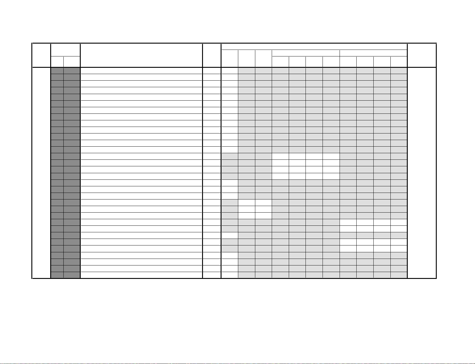
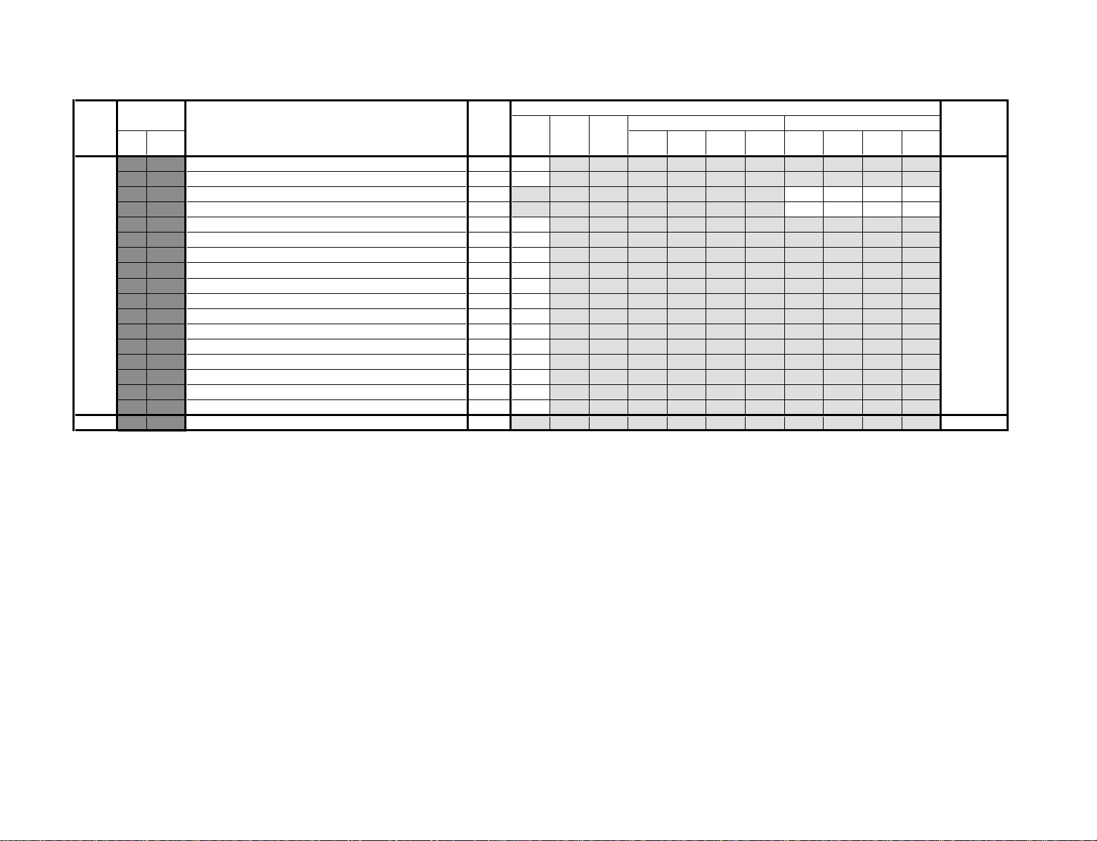
5-2. SERVICE LIST
Note
• Common : The data value of each mode commonness. Others are set up by each mode.
• : Shaded items are fixed data.
• : Though data value is indicated on the screen, it is not used.
• Standard data listed on the Adjustment Item Table are reference values, therefore it may be different for each model and for each
mode.
• Note for Different Data :
Those are the standard data values written on the microprocessor. Therefore, the data values of the modes and stored respectively
in the memory.
In case of a device replacement, adjustment by rewriting the data value is necessary for some items.
OPTION NOTE
Category : OPM
Item : COM Comb Operation Selection 00 = automatic operation (depends on color system status)
01 = no comb operation
02 = forced 2D-comb operation
03 = forced 3D-comb operation
RM-961
Item : TSY TV System Selection for Auto TV System 00 = B/G, 01 = I, 10 = D/K, 11 = M
Item : SSO Speed CH Search Selection 00 = normal, 01 = 4 times, 10 = 6 times, 11 = 8 times
Item : TRP MPEG/JPEG Noise Reduction
Bit bit7 bit6 bit5 bit4 bit3 bit2 bit1 bit0
Input ––TV Video 1 Video 2 Video 3 Video 4 DVD
Category : OPB
OP1 bit7 bit6 bit5 bit4 bit3 bit2 bit1 bit0
Item TOP NICAM HDEV (reserved) – DVD Input AV Input
Data 11100111
AV Input 00 = no AV Input 01 = 1 AV Input
10 = 3 AV Input 11 = 4 AV Input
OP2 bit7 bit6 bit5 bit4 bit3 bit2 bit1 bit0
Item C-Text
Data 00010011
C-Text Text Decoder Selection 0 = original, 1 = chinese
Korean Stereo* Korean Stereo 0 = disabled, 1 = enabled
Video NTSC 3.58* Video Color System 0 = Multi System, 1 = Single System
A-TVsys Auto TV System in Auto Program 0 = disabled, 1 = enabled
US ST* USA Stereo 0 = disabled, 1 = enabled
SSV Model SSV-production Model 0 = original, 1 = disable PIP/TWIN/Digital
OSD Language 00 = English only, 01 = English & Chinese,
* : APPLICABLE FOR NTSC MODELS ONLY
Korean Korean
Stereo Mode Mode
10 = English & Arabic/Korean* 11 = English, Chinese & Arabic/Korean*
A-TVsys US ST
SSV
OSD Language
– 20 –
V : WIDE (V-Compressed) mode
DRC
1250 V
Standerd Data
PIP
PIP V
00
INDEX TWIN
DRC
100
ECOONECO
OFF
ECO
ON V
ECO
OFF V
Device NameFunction
KP-ER43M31/M61/M90/M91, ER53M31/M61/M90/M91
RM-961
Category
GEO 00 VSZ V SIZE 00 ~ 3F 1F 1F 1F 1F 1F 1F 1F 1F 1F 1F 1F 1F CXA2100AQ
– 21 –
DAC 00 HCT H CENTER 00 ~ FF MB88141
Item
No. Name
01 VPS V POSITION 00 ~ 3F 23 23 1F 1F 23 1F 1F 1F 1F 1F 1F 1F
02 VLN V LINEARITY 00 ~ 0F 07 07 07 07 07 07 07 07
03 SCO S CORRECTION 00 ~ 0F 07 07 07 07 07 07 07 07
04 HSZ H SIZE 00 ~ 3F 33 33 33 33 33 33 33 33 33 33 33 33
05 HPS H POSITION 00 ~ 3F 37 37 37 37 37 37 37 37 37 37 37 37
06 DVH H POSITION OFFSET FOR DVD 00 ~ 0F 09 07
07 PAP PIN AMP 00 ~ 3F 22 22 22 22 22 22 22 22
08 UPN UPPER CORNER PIN 00 ~ 3F 22 22 22 22 22 22 22 22 22 22 22 22
09 LPN LOWER CORNER PIN 00 ~ 3F 22 22 22 22 22 22 22 22 22 22 22 22
0A TRZ TRAPEZIUM 00 ~ 0F 06 06 06 06 06 06 06 06 06 06 06 06
0B AGL AFC ANGLE 00 ~ 0F 07 07 07 07 07 07 07 07
0C BOW AFC BOW 00 ~ 0F 07 07 07 07 07 07 07 07
0D LBL LEFT H BLANKING 00 ~ 3F 34 34 34 34 34 34 34 34 34 34 34 34
0E RBL RIGHT H BLANKING 00 ~ 3F 1F 1F 1F 1F 1F 1F 1F 1F 1F 1F 1F 1F
0F MPN MIDDLE PIN DISTORTION COMPENSATION 00 ~ 03 00 00 00
10 UVL UPPER V LINEARITY 00 ~ 0F 00 00
11 LVL LOWER V LINEARITY 00 ~ 0F 00 00
12 HCP HORIZONTAL HIGH VOLTAGE COMPENSATION 00 ~ 03 01 01 01
13 VCP VERTICAL HIGH VOLTAGE COMPENSATION 00 ~ 03 00 00 00
14 VAS V ASPECT 00 ~ 3F 2F 2F 2F 2F 2F 2F 2C 2F 2C 2F 2F 2F
15 VSC V SCROLL 00 ~ 3F 1F 1F 1F 1F 1F 22 22 22 22 22 22 22
16 USC UNDER-SCAN MODE ON/OFF 00, 01 00 00 01
17 VBW V BLANKING WIDTH CONTROL 00 ~ 03 00 00 00 00 03 00 03 00
18 AT1 AKB REFERENCE TIMING 00 ~ 03 00 00 00 00 00 00 00 00
19 CPY COPY THE GEO DATA TO ALL 50/60Hz NVM AREA 00, 01
01 HLN H LINEARITY 00 ~ 3F
02 MDP MIDDLE PIN 00 ~ 3F
03 CCP LOWER CORNER PIN 00 ~ 3F
04 HTR HORIZONTAL TRAPEZIUM 00 ~ 3F
05 DF DF ON/OFF SWITCH 00, 01
06 DPH DF PHASE 00 ~ 3F
07 QPH QP PHASE 00 ~ 3F
08 QAC QP AMPLITUDE 00 ~ 3F
09 QDC QP DC LEVEL 00 ~ 3F
0A QDV QP V MODULATION 00 ~ 3F
0B QAV QP AMPLITUDE MODULATION 00 ~ 3F
0C ABC ABL D/A CONTROL 00 ~ FF 00 00 7E 7E
0D CPY COPY THE DAC DATA TO ALL 50/60Hz NVM AREA 00, 01
Data
Range
DRC
1250
50Hz (PAL) 60Hz (NTSC) ECO Mode
DRC
PIP INDEX TWIN
100
DRC
1250
Category Device NameFunction
WHB 00 CBO DC OFFSET CANCELLER FOR CB1 00 ~ 0F 0A CXA2100AQ
Item
No. Name Common
01 CRO DC OFFSET CANCELLER FOR CR1 00 ~ 0F 0A
02 SBR SUB BRIGHTNESS CONTROL 00 ~ 3F 25
03 RDR R DRIVE 00 ~ 3F 29
04 GDR G DRIVE 00 ~ 3F 29
05 BDR B DRIVE 00 ~ 3F 29
06 RCT R CUTOFF 00 ~ 3F 29
07 GCT G CUTOFF 00 ~ 3F 1A
08 BCT B CUTOFF 00 ~ 3F 29
09 SBO SUB BRIGHTNESS OFFSET 00 ~ 3F 1F
0A RDO R DRIVE OFFSET 00 ~ 3F 1F
0B GDO G DRIVE OFFSET 00 ~ 3F 1F
0C BDO B DRIVE OFFSET 00 ~ 3F 1F
0D RCO R CUTOFF OFFSET 00 ~ 3F 1F
0E GCO G CUTOFF OFFSET 00 ~ 3F 1F
0F BCO B CUTOFF OFFSET 00 ~ 3F 1F
– 22 –
Data
Range
Standerd Data
KP-ER43M31/M61/M90/M91, ER53M31/M61/M90/M91
RM-961
V : WIDE (V-Compressed) mode
Twin IndexCommon
Standerd Data
ECOONECO
OFF
ECO
ON V
ECO
OFF V
Device Name
KP-ER43M31/M61/M90/M91, ER53M31/M61/M90/M91
Category
SAJ 00 PIC PICTURE CONTROL 00 ~ 3F 3F 2C 1C CXA2100AQ
– 23 –
JGL 00 PON
Item
No. Name TV Video DVD TV Video DVD Dynamic Standard Hi-Fine Personal
01 BRT BRIGHTNESS CONTROL 00 ~ 3F 21 1F 1B
02 COL COLOR CONTROL 00 ~ 3F 27 23 1F
03 HUE HUE CONTROL 00 ~ 3F 1F 1F 1F
04 SHP SHARPNESS CONTROL 00 ~ 3F 22 1F 1D
05 VML VM LEVEL 00 ~ 03 03 03 02 03
06 DYC DYNAMIC COLOR ON/OFF 00, 01 01 01 00 01
07 CTM COLOR TEMPERATURE FOR DYNAMIC COLOR 00, 01 00 00 00 00
08 CAX COLOR MATRIX SPECIFICATION 00 ~ 03
09 GMA GAMMA CORRECTION 00 ~ 03 03 03 03 03
0A DCT DC TRANSMISSION CONTROL 00 ~ 03 01 00 00 00
0B DPL AUTO PEDESTAL LEVEL CONTROL 00 ~ 03 02 01 00 01
0C ABM ABL MODE CONTROL 00 ~ 03 01 00 00 00
0D ABT ABL CURRENT DETECTION Vth CONTROL 00 ~ 03 02 00 02 00
0E CLO COLOR OFFSET 00 ~ 0F 07 07 0C 0C
0F CLW COLOR STEP WIDTH TO THE CHANGE OF S/N 00 ~ 07 01
10 HUO HUE OFFSET 00 ~ 0F 08 08 09 09
11 SHO SHARPNESS OFFSET 00 ~ 1F 0F 0F 0F 0C 0F 0F
12 SHW
13 PIO PICTURE OFFSET FOR TWIN/INDEX 00 ~ 07 07 07
14 BRO BRIGHTNESS OFFSET 00 ~ 0F 07 07 07 07
01 RGB RGB OUTPUT SELECTION 00 ~ 07 07
02 AGG AGING MODE SELECTION 00 ~ 03 00
03 DPS Y/C DELAY LINE PASS MODE SWITCH 00, 01 00
04 BBT RGB BOTTOM LIMITTER CONTROL 00 ~ 03 03
05 LML RGB AMPLITUDE LIMITTER CONTROL 00 ~ 03 00
06 PAB DC LEVEL FOR PEAK ABL 00 ~ 0F 0F
07 SCO SUB PICTURE CONTROL 00 ~ 0F 07
08 LV2 RGB LEVEL FOR RGB2 00 ~ 0F 06
09 SF0 SHARPNESS CIRCUIT F0 00, 01 01 01 01 01 01 01
0A PRO PRE/OVER-SHOOT RATIO CONTROL 00 ~ 03 00 03 03 03 03 03
0B LTI LUMINANCE TRANSIENT IMPROVEMENT 00 ~ 03 02 02 00 02
0C CTI CHROMINANCE TRANSIENT IMPROVEMENT 00 ~ 03 01 01 00 01
SHARPNESS STEP WIDTH TO
THE CHANGE OF S/N
RGB AND AKB REFERENCE PULSE
OUTPUT ON/OFF
Function
Data
Range
00 ~ 07 01
00, 01 01 CXA2100AQ
50Hz (PAL) 60Hz (NTSC) ECO ModePicture Mode
02 00
RM-961
Category
YCT 00 TNT TINT ADJUSTMENT FOR NTSC 00 ~ 3F CXA2123Q
– 24 –
Item
No. Name
01 PNG PAL/NTSC GATE WIDTH 00, 01 01
02 PNI PAL/NTSC SENSITIVITY SW 00, 01 00
03 SCL SUB COLOR CONTROL 00 ~ 0F 07 07 07 07
04 SCT SUB CONTRAST CONTROL 00 ~ 0F 08 07 08 07
05 SF0 SHARPNESS CENTER FREQUENCY CHANGING 00 ~ 03 02
06 SEQ SHARPNESS EQUALIZER CHARACTERISTIC 00 ~ 03 03
07 SHG SHARPNESS GAIN CONTROL 00 ~ 0F 05 06 05 06 05 05
08 YOL Y-OUTPUT LEVEL CONTROL 00 ~ 3F 1F
09 BSP BLACK STRETCH START POINT CHANGING 00 ~ 03 00
0A COL CB/CR OUTPUT LEVEL CONTROL 00 ~ 3F 1A
0B DCR DC RESTORATION RATIO ADJUSTMENT 00 ~ 03 00
0C BF0 BPF/TQF F0 ADJUSTMENT 00 ~ 03 01
0D BFQ BPF/TQF Q ADJUSTMENT 00 ~ 03 02
0E FSW BPF/TQF SWITCH 00, 01 01
0F SDT SECAM DOUBLE TRAP SWITCH 00, 01 01
10 LPF Y/CB/CR LPF SWITCH 00, 01 01
11 YDL Y-DL TIME ADJUSTMENT 00 ~ 0F 06 05 05 03
12 CMT CB/CR OUTPUT MUTE SWITCH 00, 01 00
13 BO1 CB OFFSET ADJUSTMENT (MAIN ROUTE) 00 ~ 0F 07
14 RO1 CR OFFSET ADJUSTMENT 00 ~ 0F 07
15 CDF V COUNT DOWN FREQUENCY SWITCH 00 ~ 07 00
16 CDM V COUNT DOWN JUDGE SWITCH 00 ~ 03 00
17 AFC AFC SENSITIVITY SWITCH 00 ~ 03
18 MVM MACROVISION MASK + AFC MASK 00, 01 00
19 SRY SECAM R-Y BLACK ADJUSTMENT 00 ~ 0F 07
1A SBY SECAM B-Y BLACK ADJUSTMENT 00 ~ 0F 01
1B BEL SECAM BELL/HPF SWITCHING 00 ~ 03 02
1C BLF BELL F0 ADJUSTMENT 00, 01 00
1D SVI SECAM V-ID SWITCH 00, 01 00
1E SGP SECAM GATE POSITION ADJUSTMENT 00 ~ 03 00
1F SID SECAM SENSITIVITY SWITCH 00, 01 01
20 SIH SECAM INHIBITION SWITCH 00, 01 00
21 STP Y BLACK LEVEL SETUP FOR PAL PLUS 00, 01 00
22 HVC H-VCO TEMPERATURE CHARACTER CANCELLING 00 ~ 03 02
23 3NR 3D NR OPERATION ON/OFF 00, 01 01
24 BW6 3D NR FOR 60Hz NON-BURST SIGNAL ON/OFF 00, 01 01
25 WSH SHARPNESS GAIN STEP FOR NOISE REDUCTION 00 ~ 03 00
26 WCO CB/CR OUTPUT LEVEL STEP FOR NOISE REDUCTION 00 ~ 03 00
Data
Range
Common 2D Comb 3D Comb S-Input others
Standerd Data
50Hz
(PAL)
TV Video DVD
60Hz
(NTSC)
24 1F
50Hz
(PAL)
60Hz
(NTSC)
00 00
50Hz
(PAL)
(NTSC)
Device NameFunction
60Hz
KP-ER43M31/M61/M90/M91, ER53M31/M61/M90/M91
RM-961
Category
SYC 00 TNT TINT ADJUSTMENT FOR NTSC 00 ~ 3F CXA2123Q
– 25 –
Item
No. Name SECAM NTSC PAL
01 PNG PAL/NTSC GATE WIDTH 00, 01 01
02 PNI PAL/NTSC SENSITIVITY SW 00, 01 00
03 SCL SUB COLOR CONTROL 00 ~ 0F 06 06 07 07
04 SCT SUB CONTRAST CONTROL 00 ~ 0F 08 07 08 07
05 SF0 SHARPNESS CENTER FREQUENCY CHANGING 00 ~ 03 02
06 SEQ SHARPNESS EQUALIZER CHARACTERISTIC 00 ~ 03 03
07 SHG SHARPNESS GAIN CONTROL 00 ~ 0F 07
08 YOL Y-OUTPUT LEVEL CONTROL 00 ~ 3F 1F
09 BSP BLACK STRETCH START POINT CHANGING 00 ~ 03 00
0A COL CB/CR OUTPUT LEVEL CONTROL 00 ~ 3F 1A
0B DCR DC RESTORATION RATIO ADJUSTMENT 00 ~ 03 00
0C BF0 BPF/TQF F0 ADJUSTMENT 00 ~ 03 01
0D BFQ BPF/TQF Q ADJUSTMENT 00 ~ 03 02
0E FSW BPF/TQF SWITCH 00, 01 01
0F SDT SECAM DOUBLE TRAP SWITCH 00, 01 01
10 LPF Y/CB/CR LPF SWITCH 00, 01 01
11 YDL Y-DL TIME ADJUSTMENT 00 ~ 0F 05 03 02 03
12 NCM 1-H ADDITION SWITCH 00, 01 01
13 CMT CB/CR OUTPUT MUTE SWITCH 00, 01 00
14 BO1 CB OFFSET ADJUSTMENT (MAIN ROUTE) 00 ~ 0F 07
15 RO1 CR OFFSET ADJUSTMENT 00 ~ 0F 07
16 CDF V COUNT DOWN FREQUENCY SWITCH 00 ~ 07 00
17 CDM V COUNT DOWN JUDGE SWITCH 00 ~ 03 00 00
18 AFC AFC SENSITIVITY SWITCH 00 ~ 03
19 MVM MACROVISION MASK + AFC MASK 00, 01 00
1A SRY SECAM R-Y BLACK ADJUSTMENT 00 ~ 0F 07
1B SBY SECAM B-Y BLACK ADJUSTMENT 00 ~ 0F 01
1C BEL SECAM BELL/HPF SWITCHING 00 ~ 03 02
1D BLF BELL F0 ADJUSTMENT 00, 01 00
1E SVI SECAM V-ID SWITCH 00, 01 00
1F SGP SECAM GATE POSITION ADJUSTMENT 00 ~ 03 00
20 SID SECAM SENSITIVITY SWITCH 00, 01 01
21 SIH SECAM INHIBITION SWITCH 00, 01 00
22 STP Y BLACK LEVEL SETUP FOR PAL PLUS 00, 01 00
23 HVC H-VCO TEMPERATURE CHARACTER CANCELLING 00 ~ 03 02
Data
Range
Common
S-Input
Col Mode
Standerd Data
50Hz
(PAL)
TV Video
60Hz
(NTSC)
21 20
50Hz
(PAL)
00
60Hz
(NTSC)
DVD
Device NameFunction
KP-ER43M31/M61/M90/M91, ER53M31/M61/M90/M91
RM-961
Category
43" 00 BAS BASS CONTROL 00 ~ 0F 0B 0A 07 TDA7315
53" 00 BAS BASS CONTROL 00 ~ 0F 09 07 05
Item
No. Name Common Sur VDD Sur VDP Sur TRS Sur SIM Sur OFF Dynamic Drama Soft
01 TRE TREBLE CONTROL 00 ~ 0F 0A 09 07
02 LDN LOUDNESS ON/OFF 00, 01 01
01 TRE TREBLE CONTROL 00 ~ 0F 0B 09 06
02 LDN LOUDNESS ON/OFF 00, 01 01
Sur : Surround mode
VDD : Virtual Dolby Digital
VDP : Virtual Dolby Prologic
TRS : Tru Surround
SIM : Simulated
– 26 –
Category Device NameFunction
MSP 00 WST W/G STEREO THRESHOLD 00 ~ FF 15 MSP3415D
Item
No. Name Common
01 WBT W/G BILINGUAL THRESHOLD 00 ~ FF EA
02 WLL W/G MONAURAL THRESHOLD 00 ~ FF 05
03 WAC W/G AGREEMENT COUNT 00 ~ 0F 01
04 WDL W/G SEARCH DELAY 00 ~ FF 30
05 NDL NICAM SEARCH DELAY 00 ~ FF 20
06 SDL STEREO STATUS READ DELAY 00 ~ FF 10
07 AGC AGC SWITCH AUTO/CONSTANT 00, 01 01
08 REL AGC GAIN AT CONSTANT MODE 00 ~ 3F 28
09 CRM CARRIER MUTING ON/OFF 00, 01 00
0A ACO AUDIO CLOCK OUT ON/OFF 00, 01 01
0B FP FM PRESCALE FOR NON-M SYSTEM 00 ~ 7F 1B
0C FPM FM PRESCALE FOR M SYSTEM 00 ~ 7F 32
0D FH FM PRESCALE FOR HDEV 00 ~ 7F 2D
0E FHM FM PRESCALE FOR HDEV AND M 00 ~ 7F 65
0F WGP W/G PRESCALE 00 ~ 7F 2A
10 NIP NICAM PRESCALE 00 ~ 7F 6D
11 ERR AUTO FM SWITCH THRESHOLD 00 ~ FF 50
12 VOL LOUD SPEAKER GAIN 0700h to 07FFh 00 ~ FF 6D
Data
Range
Data
Range
Standerd Data
Standerd Data
Device NameFunction
KP-ER43M31/M61/M90/M91, ER53M31/M61/M90/M91
RM-961
Category
LTI 00 LDH HISTOGRAM SEGMENT SELECTION 00, 01 01 TDA9178
– 27 –
Item
No. Name Dynamic Standard Hi-Fine Personal
01 CFS CONTOUR FILTER SELECTION 00, 01 01
02 WLB LETTERBOX WINDOW SWITCH 00, 01 00
03 VDC VIDEO DEPENDENT CORING 00, 01 01 01 01 01
04 DEM DEMONSTRATION MODE 00, 01 00
05 CDP LUMINANCE DELAY 00 ~ 07 04
06 OSP OVERRULE SMART PEAKING 00, 01 00
07 WPO WHITE POINT STRETCH OFF 00, 01 00
08 DSK SKIN TONE SWITCH 00, 01 00 00 00 00
09 ASK SKIN TONE ANGLE SELECTION 00, 01 00
0A WSK SKIN TONE WIDTH SELECTION 00, 01 00
0B SSK SKIN TONE SIZE SELECTION 00, 01 00
0C DGR GREEN ENHANCEMENT SWITCH 00, 01 00
0D DGT THRESHOLD OF GREEN ENHANCEMENT SWITCH 00 ~ 07 07
0E GGR GREEN ENHANCEMENT GAIN 00, 01 00
0F WGR GREEN ENHANCEMENT WIDTH 00, 01 00
10 SGR GREEN ENHANCEMENT SIZE 00, 01 00
11 DBL BLUE STRETCH SWITCH 00, 01 00
12 GBL BLUE STRETCH GAIN SELECTION 00, 01 00
13 SBL BLUE STRETCH SIZE SELECTION 00, 01 00
14 CDS COLOR DEPENDENT SHARPNESS 00, 01 01 01 01 01
15 CST THRESHOLD OF COLOR DEPENDENT SHARPNESS 00 ~ 07 07
16 CTI COLOR TRANSIENT IMPROVEMENT 00, 01 00 00 00 00
17 BON BLACK OFFSET COMPENSATION 00, 01 00 00 00 00
18 BTD ADAPTIVE BLACK STRETCH 00 ~ 3F 00 00 00 00
19 NLD NON-LINEARITY AMPLIFIER 00 ~ 3F 00 13 13 05 13
1A NLW STEP WIDTH OF NON-LINEARITY AMPLIFIER 00 ~ 07 07
1B VGD VARIABLE GAMMA 00 ~ 3F 1F 15 15 1A 15
1C VGW STEP WIDTH OF VARIABLE GAMMA 00 ~ 07 00
1D PKD PEAKING AMPLITUDE 00 ~ 3F 32 32 1D 32
1E PKW STEP WIDTH OF PEAKING AMPLITUDE 00 ~ 0F 08
1F SPD STEEPNESS CORRECTION 00 ~ 3F 00 00 00 00
20 CRD CORING LEVEL 00 ~ 3F 14 0D 05 14
21 CRW STEP WIDTH OF CORING LEVEL 00 ~ 0F 09
22 CRO CORING LEVEL OFFSET FOR VIDEO MODE 00 ~ 0F 05
23 LWD LINE WIDTH CORRECTION 00 ~ 3F 1F
24 SNM S/N MODE UNDER UNRELIABLE S/N CONDITION 00 ~ 07 00
25 SNC S/N RATIO AVERAGE COUNTER 00 ~ 0F 03 03
26 FMC FEATURE MODE MATCHING COUNTER 00 ~ 0F 02
Data
Range
Common
Twin
TV
Standerd Data
Video
Picture Mode
*
01 00 01
Device NameFunction
KP-ER43M31/M61/M90/M91, ER53M31/M61/M90/M91
Mark Data Value GE/HK/ME model: 01
*
AUS model: 00
RM-961
Category
MID 00 HPH HORIZONTAL ACTIVE DISPLAY AREA PHASE 00 ~ FF 3E 3E 7B 78 3E 49 49 6F 6C 49 MB94918
– 28 –
Item
No. Name DRC1250 PIP TWIN INDEX DRC100 DRC1250 PIP TWIN INDEX DRC100
01 VPH VERTICAL ACTIVE DISPLAY AREA PHASE 00 ~ 3F 15 15 20 1A 0C 25 25 2E 2D 13
02 HSZ HORIZONTAL ACTIVE DISPLAY AREA SIZE 00 ~ FF 7F 7F 7F 7F 7F 7F 7F 7F 7F 7F
03 VSZ VERTICAL ACTIVE DISPLAY AREA SIZE 00 ~ FF 7F 7F 7F 7F 7F 7F 7F 7F 7F 7F
04 HPW DISPLAY H-SYNC PULSE WIDTH 00 ~ 3F 3F 3F 3F 3F 3F 3F 3F 3F 3F 3F
05 VPW DISPLAY V-SYNC PULSE WIDTH 00 ~ 07 03 03 03 03 03 03 03 03 03 03
06 YDL DISPLAY OUTPUT Y/C DELAY CORRECTION 00 ~ 3F 00 00 00 00 00 00 00 00 00 00
07 MHP MAIN PICTURE HORIZONTAL POSITION (SINGLE & PIP) 00 ~ FF 7F 7F 7F 7F 7F 7F
08 MVP MAIN PICTURE VERTICAL POSITION (SINGLE & PIP) 00 ~ FF 7F 7F 7F 7F 7F 7F
09 MHS MAIN PICTURE HORIZONTAL SIZE (SINGLE & PIP) 00 ~ FF 7F 7F 7F 7F 7F 7F
0A MVS MAIN PICTURE VERTICAL SIZE (SINGLE & PIP) 00 ~ FF 7F 7F 7F 7F 7F 7F
0B PHP PIP SUB PICTURE HORIZONTAL POSITION 00 ~ FF 6B 53
0C PVP PIP SUB PICTURE VERTICAL POSITION 00 ~ FF 5E 57
0D PHS PIP SUB PICTURE HORIZONTAL SIZE 00 ~ FF 7F 7F
0E PVS PIP SUB PICTURE VERTICAL SIZE 00 ~ FF 7F 7F
0F PHO PIP SUB PICTURE HORIZONTAL POSITION OFFSET 00 ~ FF 76 68
10 PVO PIP SUB PICTURE VERTICAL POSITION OFFSET 00 ~ FF 6E 6B
11 TMP TWIN MAIN PICTURE HORIZONTAL POSITION 00 ~ 03 01
12 TSP TWIN SUB PICTURE HORIZONTAL POSITION 00 ~ FF 00
13 TVP TWIN MAIN & SUB PICTURE VERTICAL POSITION 00 ~ FF
14 THS TWIN MAIN & SUB PICTURE HORIZONTAL SIZE 00 ~ FF
15 TVS TWIN MAIN & SUB PICTURE VERTICAL SIZE 00 ~ FF
16 THO TWIN MAIN & SUB PICTURE HORIZONTAL POSITION OFFSET 00 ~ FF
17 TVO TWIN MAIN & SUB PICTURE VERTICAL POSITION OFFSET 00 ~ FF
18 XHS INDEX SUB PICTURE HORIZONTAL SIZE 00 ~ FF
19 XVS INDEX SUB PICTURE VERTICAL SIZE 00 ~ FF
1A XHG INDEX HORIZONTAL GAP WIDTH BETWEEN PICTURES 00 ~ FF
1B XVG INDEX VERTICAL GAP WIDTH BETWEEN PICTURES 00 ~ FF
1C XHP INDEX 1st SUB PICTURE HORIZONTAL POSITION 00 ~ FF
1D XVP INDEX 1st SUB PICTURE VERTICAL POSITION 00 ~ FF
1E DHP DRC HORIZONTAL ACTIVE AREA POSITION 00 ~ FF 7F 7F
1F DHS DRC HORIZONTAL ACTIVE AREA PIXEL SIZE 00 ~ FF 7F 7F
20 DVP DRC VERTICAL ACTIVE ARE LINE POSITION 00 ~ 3F 1A 1A
21 DVS DRC VERTICAL ACTIVE AREA LINE SIZE 00 ~ FF 7F 7F
22 VHP VDO HORIZONTAL ACTIVE AREA POSITION 00 ~ FF
23 VHS VDO HORIZONTAL ACTIVE AREA PIXEL SIZE 00 ~ FF
24 VEP VDO VERTICAL ACTIVE AREA EVEN POSITION 00 ~ 3F
25 VVS VDO VERTICAL ACTIVE AREA LINE SIZE 00 ~ FF
26 VOP VDO VERTICAL ACTIVE AREA ODD POSITION 00 ~ 03
27 CLT VDO CLAMP PULSE OUTPUT TIMING 00 ~ FF
28 CLW VDO CLAMP PULSE WIDTH 00 ~ 07
29 VYD VDO ANALOG INPUT Y/C DELAY CORRECTION 00 ~ 3F
2A VCR VDO CHROMA SIGNAL ORDER 00, 01
2B VDI VDO DIGITAL ANGLE INPUT SELECTION 00 ~ 03
Data
Range
50 Hz (PAL) 60 Hz (NTSC)
7F 7F
7F 7F
1A 3F
7F 7F
7F
7F
1E
7F
00
7F
04
00
01
01
Standerd Data
Device NameFunction
KP-ER43M31/M61/M90/M91, ER53M31/M61/M90/M91
7F
7F
1A
7F
7F
7F
39
7F
7F
7F
1B
7F
00
7F
04
00
01
01
RM-961
Category
3CM 00 FRZ EXTERNAL MEMORY TEST BIT 00, 01 00 µPD64082
– 29 –
Item
No. Name
01 NRM NOISE REDUCTION OPERATION MODE 00 ~ 03 00
02 YCO Y/C SINGLE OUTPUT SELECTION 00 ~ 0F 0D
03 SYC SYSTEM CLOCK SELECTION 00 ~ 03 01
04 STD STANDARD/NON-STANDARD OPERATION SELECTION 00 ~ 03 00
05 MSS INTER-FRAME/INTER-LINE OPERATION SELECTION 00 ~ 03 00
06 KIL KILLER/NON-KILLER OPERATION SELECTION 00 ~ 03 03
07 EAD EXTERNAL Y-ADC SWITCH 00, 01 00
08 ECS EXTERNAL C-SYNC INPUT SELECTION 00 ~ 03 01
09 CPP ADC INPUT LEVEL & CLUMP PULSE WIDTH SELECTION 00 ~ 03 02
0A PWR ADC INPUT WIDTH SWITCH 00, 01 00
0B HDP HORIZONTAL PHASE ADJUSTMENT 00 ~ 07 05
0C CDL C-SIGNAL DELAY ADJUSTMENT 00 ~ 07 04
0D DYC DY DETECTION CORING LEVEL ADJUSTMENT 00 ~ 0F 02 02 02 04
0E DYG DY DETECTION GAIN ADJUSTMENT 00 ~ 0F 0A 0A 0A 0A
0F DCC DC DETECTION CORING LEVEL ADJUSTMENT 00 ~ 0F 05 03 03 05
10 DCG DC DETECTION GAIN ADJUSTMENT 00 ~ 0F 05 0A 0A 05
11 YNR YNR NON-LINEAR FILTER SETUP 00 ~ 0F 01
12 CNR CNR NON-LINEAR FILTER SETUP 00 ~ 0F 01
13 WSC NOISE DETECTION CORING ADJUSTMENT 00 ~ 03 01
14 VTH HYSTERESIS SELECTION FOR H-SYNC NON-STANDARD 00 ~ 03 01 01
15 VTR SENSITIVITY SELECTION FOR H-SYNC NON-STANDARD 00 ~ 03 01 01
16 LDR SENSITIVITY SELECTION FOR FRAME-SYNC NON-STANDARD 00 ~ 03 02 01
17 VAP GAIN ADJUSTMENT FOR VERTICAL SHAPE CORRECTION 00 ~ 07 03 02 00 02
18 VAI VANISHING ADJUSTMENT FOR VERTICAL SHAPE CORRECTION 00 ~ 1F 0C 06 00 06
19 TST TEST BIT 00, 01 00
1A YPF CENTER FREQUENCY SELECTION FOR Y-PEAKING BPF 00 ~ 03 03 03 03 03
1B YPG GAIN ADJUSTMENT FOR Y-PEAKING BPF 00 ~ 0F 08 08 08 08
1C VSE LINE COMB FILTER SETUP 00 ~ 0F 0A
1D CCN C-SIGNAL SPLIT FILTER SWITCH 00, 01 00
1E COS C-SIGNAL DELAY SWITCH AT NOISE REDUCTION 00, 01 00
1F SDC DC DETECTION SENSITIVITY SWITCH 00, 01 00
Function
Data
Range
Common TV Video
NR
Mode 0NRMode 1NRMode 2NRMode 3
Standerd Data
Picture ModeNR Mode
Dynamic Standard Hi-Fine Parsonal
Device Name
KP-ER43M31/M61/M90/M91, ER53M31/M61/M90/M91
RM-961
Category
3CM 20 SDY DY DETECTION LOWER-LEVEL SENSITIVITY SWITCH 00, 01 01
– 30 –
2CM 00 APA 2D COMB APACON ON/OFF 00, 01 CXA2069Q
Item
No. Name
21 D2G D2 GAIN SELECTION 00 ~ 07 04
22 YHC Y-SIGNAL HIGHER-LEVEL CORING SELECTION 00 ~ 03 00 00 00 00
23 YHG Y-SIGNAL HIGHER-LEVEL GAIN SWITCH 00, 01 00 00 00 00
24 SHT NON-STANDARD DETECTION & H/V COUNTER TEST BITS 00 ~ 0F 00
25 CLK CLOCK TEST BITS 00 ~ 0F 08
26 PLL PLL FILTER SETUP 00 ~ 0F 0D
27 KRF KILLER DETECTION REFERENCE ADJUSTMENT 00 ~ 0F 03
28 HSL H-SYNC SLICE LEVEL ADJUSTMENT 00 ~ 0F 0C
29 VSL V-SYNC SLICE LEVEL ADJUSTMENT 00 ~ 0F 08
2A BPS INTERNAL BURST GATE START POSITION ADJUSTMENT 00 ~ 0F 04
2B BPW INTERNAL BURST GATE WIDTH ADJUSTMENT 00 ~ 0F 0A
2C ADC ADC CLOCK DELAY SELECTION 00 ~ 03 03
2D APD ADC POWER-DOWN SWITCH 00, 01 01
2E NSD NON-STANDARD DETECTION TEST BIT 00, 01 01
2F SPD MEMORY POWER-DOWN SWITCH 00 ~ 03 02
30 CNT CNR TEST BIT 00, 01 00
Function
Data
Range
Common TV Video
NR
Mode 0NRMode 1NRMode 2NRMode 3
Standerd Data
Picture ModeNR Mode
Dynamic Standard Hi-Fine Parsonal
Device Name
µPD64082
KP-ER43M31/M61/M90/M91, ER53M31/M61/M90/M91
RM-961
 Loading...