

Sony KP-65XBR10W, KP-57XBR10W Owner’s Manual


WARNING
To prevent fire or shock
hazard, do not expose the TV
to rain or moisture.
R_SK OF ELECTRIC SHOCK
DO NOT OPEN
ATTENTION
R_SQUE DE CHOC ELECTRIQUE,
NE PAS OUVRIR
PRECAUClON
RIESGO DE CHOQUE ELECTRICO
NO ABRIR
CAUTION : TO REDUCE THE RISK OF ELECTRIC SHOCK,
DO NOT REMOVE COVER (OR BACK)
NO USEI"{-SERVICEABLE PARTS iNSIDE
REFER SERVICENG TO QUALIFEED SERVICE PERSONNEL¸
._ This symbol is intended to alert the user to the
/_ This symbol is intended to alert the user to the
CAUTION
To prevent e]ectpo chock, do not use this po_adzed AC
plug with an extension cord, receptacle or other outlet
ubles_ the blades can be fully inserted to prevent blade
exposure.
presence of uninsulated "dangerous voltage"
within the product's enclosure that may be of
suffident magnitude to constitute a bek of
electric shock to persons.
presence of important operating and
maintenance (servidng) instructions in the
literature accompanying the appliance.
CAUTION
When using TV games, computers, and similar products
with your projection TV, keep the brightness and contrast
functions at low settings. Ifa fixed (non-moving) pattern is
left on the screen for long periods of time especially at a
high brightness or contrast setting, the image can be
permanenfiy imprinted onto the screen. These types of
imprints are not covered by your warranty because they
are the result of misuse.
Note on Caption Vision
This television receiver provides disp]gy of television
closed captioning in accordance with §15.119 of the FCC
rules.
Note on convergence adjustment
Before you use your projection TV, make sure to adjust
convergence. For details, see on page 25.
Note to CATV system installer
This reminder is provided to call the CATV system
installers attention to Article 82040 of the NEC that
provides guidelines for proper grounding and, in particular,
specifies that the cable ground shall be connected to the
grounding system of the building, as close to the point of
cable entry as practical.
Use of this television receiver for other than private viewing
of programs broadcast on UHF or VHF or transmitted by
cable companies for the use of the general public may
require authorization from the broadcaster/cable company
and/or program owner.
NOTIFICATION
This equipment has been tested and found to comply with
the limitsfor a Class B digital device pursuant to Part 15of
the FCC Rules. These limits are designed to provide
reasonable protection against harmful interference in a
residential installation. This equipment generates, uses,
and can radiate radio frequency energy and, ifnot installed
and used in accordance with the instructions, may cause
harmful interference with radio communications. However,
there is no guarantee that interference will not occur ina
particular installation. If this equipment does cause
harmful interference to radio or television reception, which
can be determined by turning the eduipment off and on,
the user is encouraged to try to correct the interference by
one or more of the following measures:
• Reorient or relocate the receiving antennas.
• increase the separation between the equipment and
ro3E_iver.
• Connect the equipment into an outlet on a circuit
different from that to which the receiver is connected.
• Consult the dealer or an experienced radio/TV
technician for hstp.
You are cautioned that any changes or n'_d_cafions
not expressly approved inthis manust could void your
authority to operate this equipment.
This document is for the remote control RM-Yg07
MODELS: KP-57XBRIOW, KP-g5XBR10W
Please keep this notice with the instruction manual.
As an ENERGY STAR Partner, Sony
Corporation has determined that this
product meeta the ENERGY STAR
guidetlnes for energy efficiency.
ATTENTION
Pour pr_venir les chccs _lectriques, ne pas utiliser cette
fiche poleds_e avec un prolongateur, une prise de courant
ou une autre sortie de courant, sauf si les lames peuvent
tre inser_es _ fond sans en laisser aucune pattie
decouvert.
Owner's Record
The model and sedst numbers are tocated at the rear of
the projection T_, below the Sony logo, onfoe sticker, and
also on the TV box (white label). Record these numbers in
the spaces provided below. Refer to them whenever you
call upon your Sony dealer regarding this product.
Model No.
Serist No.
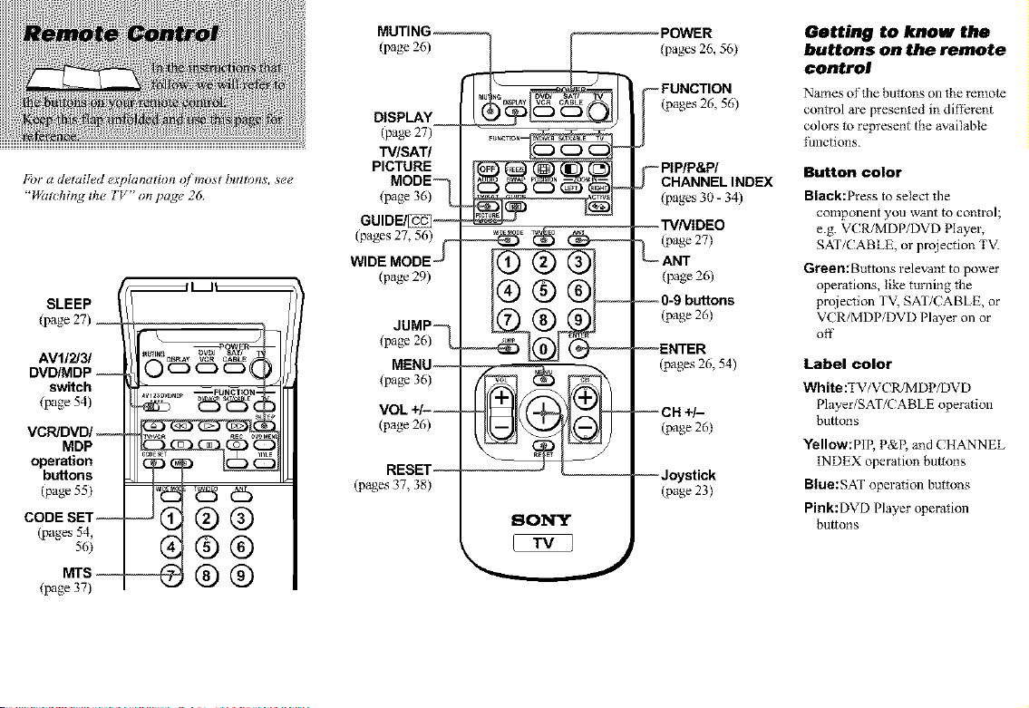
For a d,4ailed explanation o[ most buttons, see
"W_aching the TV" on page 26
SLEEP
(page27) ,__
AVl/2/3/
DVD/MDP --
switch
(_ge 54)
VCR/DVD/--
MDP
operation
buttons
(page 55)
CODE SET-
(pages 54,
56)
MTS --
(page 37)
_U_
e5
®®
g®®
(page 26) [
MU ,NO
DISPLAY
(page 27) ....... _
TV/SAT/ !_.--__--._ _--._[""
MODE
(tinge 36) "_,
PICTURE
GUlDE/_-j--
(pages 27, 56)U a,_ _
WIDE MODE_ {(11 (2) (31{
(page 29)
dUMP
(page 26) "_
MENU --
(tinge 36)
VOL +/- --
(page 26)
RESET --
(pages 37, 38)
SONY
POWER
(pages 26, 56)
-- FUNCTION
(pages 26, 56)
"--PIP/P&P/
CHANNEL INDEX
(pages 30- 34)
--W/VIDEO
"_ (page 27)
ANT
(page 26)
-- 0-9 buttons
(page 26)
--ENTER
(pages 26, 54)
--CH +/-
(page26)
--Joystick
(page 23)
Getting to know the
buttons on the remote
control
Names of the buttons on the remote
control are presented in diff?rent
colors to represent the available
lhnctions.
Button color
Black:Press to select the
component you want to control;
e.g. VCR/MDP/DVD Player,
SAT/CABLE, or prqiection TV.
Green:Buttons relevant to power
operations, like turning the
prqiection TV, SAT/CABLE, or
VCR/MDP/DVD Player on or
off
Label color
White:TV/VCR/MDP/DVD
Player/SAT/CABLE operation
buttons
Yellow:PIR P&R and CHANNEL
INDEX operation buttons
Blue:SAT operation buttons
Pink:DVD Player operation
buttons

Before You Begin
Welcome! ........................ 1
Using this Manual ................. 2
Precautions ....................... 2
Important Safeguards .............. 3
Installing and Cmmecting
the Projection TV
Carrying Your Projection TV ............. 6
Installing the Projection TV .............. 6
Mounting the Rear Speakers (not supplied).. 6
Connector Types ...................... 7
Making Connections ................... 8
Connecting Directly to a Cable or an
Antenna ...................... 8
Connecting a Cable Box ........... 9
Connecting an Antenna/Cable TV
System to a VCR .............. 10
Connecting a VCR and Projection TV to
a Cable Box .................. 11
Connecting a DTV (Digital Television)
Receiver ..................... 12
Connecting a Satellite Receiver
(SAT) ....................... 14
Connecting a Satellite Receiver
(SAT) and VCR ............... 15
Connecting a Camcorder .......... 16
Connecting Two VCRs for Tape
Editing ...................... 17
Connecting a DVD Player With S Video
or Composite Video Output
Connectors ................... 18
Connecting a DVD Player With
Component Video Output
Connectors ................... 19
Connecting an AV Receiver ....... 20
Connecting an Audio System ....... 21
Connecting an Amplifier That Supports
Dolby Pro Logic Decoder ....... 22
Basic Set Up
Using the Remote Control ............... 23
Setting Up the Pmiection TV Automatically 24
Adjusting the Convergence Automatically
(FLASH FOCUS) ................... 25
Using Your New Projection
TV
Watching the TV ...................... 26
Watching Digital TV ................... 28
Watching the Picture in Wide Screen Mode
Automatically AUTO WIDE ........ 28
Watching the Picture in Wide Screen Mode
Manually WIDEMODE ........... 29
Watching Two Programs atOne Time
.............PIP ............................ 30
Watching Two Programs at One Time
.............P&P (Twin View TM) .............. 32
Using CHANNEL INDEX ............. 33
Adjusting Your SET UP
(menus)
Learning Menu Selection ............... 35
_1 Using the VIDEO Menu ............ 36
Using the AUDIO Menu ............ 37
Adjusting the Speaker Volume for
Customized SmTound Mode ..... 38
[_ Using the TIMER Menu ............ 39
_Using the WIDE SCREEN MODE
Menu ............................ 40
I_ Using the CHANNEL SET UP Menu.. 41
Setting and Selecting FAVORITE
CHANNEL ....................... 42
Setting FAVORITE CHANNEL
manually .................... 43
Resetting FAVORITE CHANNEL
choices ..................... 43
Using FAVORITE CHANNEL .... 44
Using the SET UP Menu ............ 44
Using the PARENTAL CONTROL Feature 47
ActivatingthePARENTALCONTROL
feature...................... 47
SelectingaCustomRating........ 49
ChangingthePassword........... 51
WhattheRatingsMean................ 52
Additional Operations
Operating Video Equipment ............. 54
Setting the Manufacturer's Code . •. 54
Operating video eqtdpment ........ 55
Operating a Cable Box or Satellite Receiver
(SAT) ............................ 56
Setting the Manufacturer's Code .,. 56
Operating a cable box or satellite
receiver ..................... 56
Additional Information
Troubleshooting ..................... 57
Specifications ........................ 60
Index ............................... 61
* Manuf5cmred under license ti'om Dolby Laboratories
Licensing Corporagon. Additionally licensed under
Canadian patent number 1,037,877 "Dolby," the double-D
symbol [113and '_P_o Logic" are trademarks of Dolby
Laboratories Licensing Corporation
Welcome!
Thank you for purchasing the Sony Projection TV.
This manual is for models KP_57XBR10W and
KP_65XBR10Wi
Model KP_57XBR10W is used for illustration
pml_oses.
The features you will enjoy include:
• "I 080i Capable," enabling you to receive the 1080i,
720p, 480p and 480i digital TV formats. By using
the VIDEO 5 (DTV) IN jacks, you can connecl a
DTV (digital television) receiver to view DTV
programs.
The VIDEO 5 (DTV) IN jacks also fimction as R/
G/B connectors with SYNC signal (HD/VD), but
are nol compatible with a computer's 5BNC video
output conilectors.
• WIDE SCREEN MODE, allowing you to walch 4:3
normal broadcasts in wide screen mode (I 6:9 aspect
ratio).
• AUTO WIDE, allowing you to select the wide
screen mode autom_rically.
• PARENTAL CONTROL, enabling you to block
programs th_ are unsuitable for your children.
• DRC (Digital Reality Creation), a technology
unique _oSony, allowing you to obtain a finer, more
detailed picture with four-times higher density than
the conventional NTSC picture. (not available lbr
input fi'om the VIDEO 5 (DTV) IN jacks)
• MID (Multi hnage Drive0, a newly developed
device, allowing you to enjoy the lbllowing features
and, at the same time, to use your projection TV
easily. (not available for input from the VIDEO 5
(DTV) IN jacks)
Picture & Picture (P&P) with zoom-in lhnction
(Twin View IM)
Picture-in-Picture (PIP)
CHANNEL INDEX, allowing you to view mid
choose fi'om twelve programs
FAVORITE CHANNEL, allowing you to view
mid choose from eight of your favorite channels
• FLASH FOCUS, allowing you to adiust
convergence automatically.
• Two Y/PE_/Pa inputs for DVD Player connection
(480p format capabilby is on the VIDEO 5 (DTV)
IN jacks).
• Four AUDIO/VIDEO/S VIDEO inputs.
i
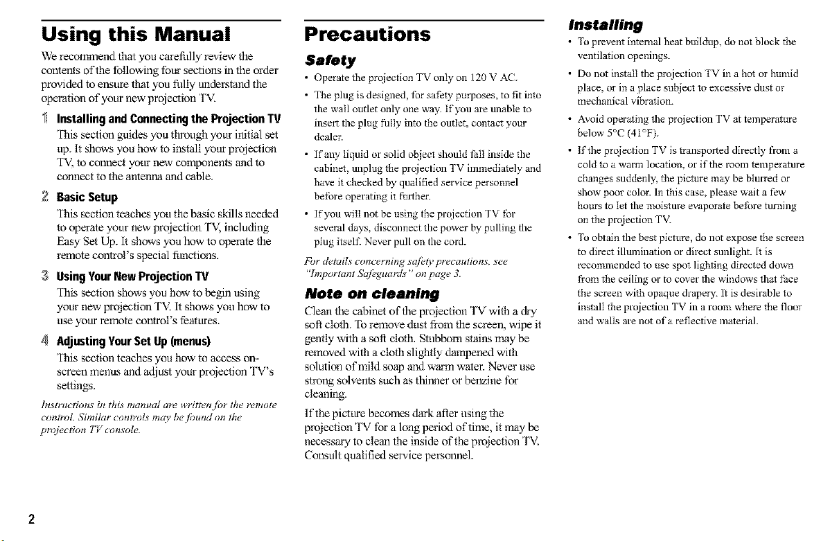
Using this Manual
We recommend that you carefully review the
contents of the following four sections in the order
provided to ensure that you frilly tmderstand the
operation of your new projection 'I'V.
Installing and Connecting the Projection TV
This section guides you through your initial set
up. It shows you how to install your projection
TV, to connect your new components and to
connect to the antenna and cable.
2 Basic Setup
This section teaches you the basic skills needed
to operate your new projection TV, including
Easy Set Up. i_ shows you how to operate the
remote control's special funcfions.
3 UsingYourNewProjectionTV
This section shows you how to begin using
your new proiection TV. it shows you how to
use your remote control's features.
4 AdjustingYourSet Up (menus)
This section teaches you how to access on-
screen menus and adjust your projection TV's
settings.
lnstmt_tions in this manual are writtetl tor the" remot¢_
_nlrol. _mi_r controls may be _und on the
proj_:t_n TV console
Precautions
Safety
• Operate fi_eprqiection TV only on 120 V AC.
• The plug is designed, [br safely pro'poses, to fit into
the wall outlet only one way. If you are unable to
insel_ the plug thlly into the outIet, contact your
dealer.
• If any liquid or solid ot_iec_ should thll inside the
cabinet, unplug the projection TV immediately and
have it checked by qualified service personnel
betbre operating it f_l_her.
• If you will not be using the projection TV tbr
several days, disconnect the power by pulling the
plug itselt_ Never pull on the cord.
NJr d_,tails concerning s@ty precautions, see
"Important Sq[_guards" on page 3.
Note on cleaning
Clean the cabinet of the pmiection TV with a d_y
soft cloth. To remove dust from the screen, wipe it
gently with a soft cloth. Stubborn stains may be
removed with a cloth slightly dampened with
solution of mild soap and warn1 water. Never use
strong solvents such as thinner or benzine for
cleaning.
If the picture becomes dark after using the
proiection TV for a long period of time, it may be
necessmy to clean the inside of the projection TV.
Consult qualified service personnel.
Installing
• To prevent internal beat buildup, do not block the
ventilation openings.
• Do not install the prqjection TV in a boi or humid
place, or in a place subiecI to excessive dust or
mechanical vibration.
• Avoid operating the prqiection TV at temperature
below" 5°C (4i°F).
• If the projection TV istranspol_ed directly from a
cold _o a warm location, or iftbe loom temperature
changes suddenly, the picture may be blurred or
show" poor color. In this case, please wait a few
hours to let the moisture evaporate before turning
on the projection TV.
• To obtain tbe best picture, do not expose the screen
to direct illumination or direct sunligbt. It is
recommended to use spot lighting directed down
fi'om the ceiling or to cover the windows that face
the screen with opaque drapery. It is desirable to
install the prqjection TV in a room where the floor
and walls are not of a reflective materiaL

Important Safeguards
For your protection, please read these instructions
completely, and keep this manual for furore
reference.
Carefhily observe and comply with all warnings,
cautions and instrtmtions placed on the set, or
described in the operating instrtlctlons or service
manual.
WARNING
_lbguard against injmy, the following basic safety
precautions shottld be observed in the installation,
use, and servicing of the set.
Use
Power Sources
only from the type of power
source indicated on the
This set should be operated
serial/model plate.
if you are not sure of the
type of electrical power
supplied to your home, consult your dealer or local
power company. For those sets designed to operate
from battery power, refer to the operating
instructions.
Grounding or Polarization
This set is equipped with a polarized AC power
cord plug (a plug having one blade wider than the
other), or with a three-wire grounding type plug (a
plug having a third pin for grounding).
Follow the instructions below:
For the set with a
polarized AC power
cord plug
This plug will fit into the power outlet only one
way. This is a safety feature. If you are unable to
insert the plug fhily into the outlet, t_y reversing
the plug. if the plug should still tZailto fit, contact
yottr electrician to have a sthiable outlet installed.
Do not defeat the safety porpose of the polarized
plug by forcing it in.
Alternate Warning
For the set with a
three-wire grounding
type AC plug
This plug will only fit into a grotmding-type power
outlet. This is a safety feature, if you are unable to
insert the plug into the outlet, contact your
electrician to have a suitable outlet installed. Do
not defeat the safety purpose of the gTounding
plug.
Overloading
Do not overload wall outlets,
extension cords or
I _: )-
convenience receptacles
beyond their capacity, since
this can result in fire or
electric shock.
Always turn the set offwhen
it is not to be used. When the
set is left unattended and
unused for long perioda of
time, unplug it from the wall
outlet as a precaution against
the possibility of an internal malftmction that
could create a fire hazard.
Object and Liquid
Entry
Never push objects of any
kind into the set through the
cabinet slots as they may
touch dangerous voltage
points or short out parts that
could result in a th-e or
electric shock. Never spill
liquid of any kind on the set.
Attachments
Do not use attachments not
recommended by the
manufacturer, as they may
cause hazards.
Cleaning
Unplug the set from the wall
outlet before cleaning or
polishing it. Do not use
liquid cleaners or aerosol
cleaners. Use a cloth lightly
dampened with water for
cleaning the exterior of the
set.
(t_mtinued)
i
3
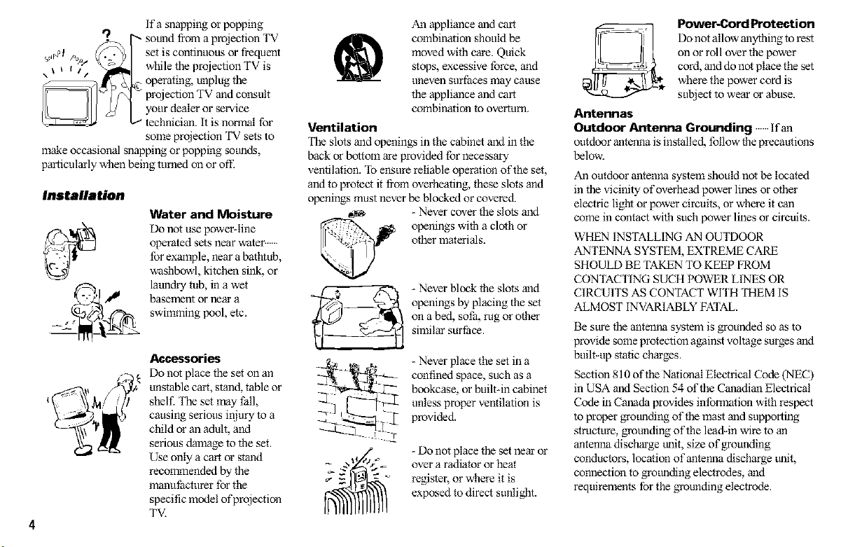
If a snapping or popping
sound from a proiection TV
set is continuous or fi-equent
while the projection TV is
operating, unplug the
projection TV and consult
your dealer or service
technician, it is normal for
some projection TV sets to
make occasional snapping or popping sotmds,
particularly when being turned on or ofl_
Installation
Water and Moisture
Do not use poweMine
operated sets near water ...........
for example, near a bathtub,
washbowl, kitchen sink, or
latmdly tub, in a wet
basement or near a
swimming pool, etc.
Accessori_
Do not place the set on an
unstable calt, stand, table or
shelf. The set may t'all,
causing serious injmy to a
child or an adult, and
serious damage to the set.
Use only a calt or stand
recommended by the
manufacturer for the
specific model of projection
TV.
An appliance and cart
combination should be
moved with care. Quick
®
Ventilation
The slots and openings in the cabinet and in the
back or bottom are provided for necessary
ventilation. 'lb ensure reliable operation of the set,
and to protect it fiom overheating, these slots and
openings must never be blocked or covered.
_j_ openings with a cloth or
___ openings by placing the set
__ - Never block the slots mid
7. -'_ (_ over a radiator or heat
_. - Do not place the set near or
stops, excessive force, and
uneven surfaces may cause
the appliance and cart
combination to overturn.
- Never cover the slots and
other materials.
on a bed, sofa, lug or other
similar surface.
- Never place the set in a
confined space, such as a
bookcase, or built-in cabinet
unless proper ventilation is
provided.
' register, or where it is
exposed to direct sunlight.
Power-Cord Protection
Do not allow anything to rest
on or roll over the power
cord, and do not place the set
where the power cord is
subject to wear or abuse.
Antennas
Outdoor Antenna Grounding Ifan
outdoor antenna is installed, follow the precautions
below.
An outdoor antenna system should not be located
in the vicinity of overhead power lines or other
electric light or power circuits, or where it can
come in contact with such power lines or circuits.
WHEN INSTALLING AN OUTDOOR
ANTENNA SYSTEM, EXTREME CA_
SHOULD BE TA_N TO KEEP FROM
CONTACTING SUCH POWER LINES OR
CIRCUITS AS CONTACT WITH THEM IS
ALMOST INVARIABLY FATAL.
Be sure the antenna system is grounded so as to
provide some protection against voltage surges and
built-up static charges.
Section 810 of the National Electrical Code (NEC)
in USA and Section 54 of the Carmdian Electrical
Code in Canada provides information with respect
to proper grotmding of the mast and supporting
strtlcture, grounding of the lead-in wire to an
antenna discharge trait, size of grounding
conductors, location of antenna discharge trait,
connection to grotmding electrodes, and
requirements for the grounding electrode.
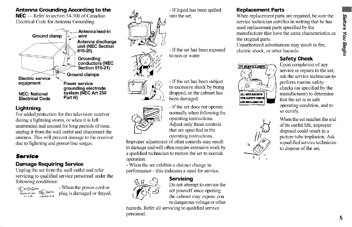
Antenna Grounding According to the
NEC Refer to section 54-300 of Canadian
Electl%al Code for Antenna Grounding.
_ Antenna lead-in
Ground clamp S wire
__unit (NEC Section
_810-20)
| Grounding
_J conductors (NEC
E_ Antenna discharge
equipment Power service
NEC: National system (NEC Art 250
Electrical Code Part H)
Lightning
For added protection for this television receiver
dining a lightning storm, or when it is left
unattended and unused for long periods of time,
unplug it from the wall outlet and disconnect the
antenna. This will prevent damage to the receiver
due to lightning and power-line surges.
_ Section 810-21)
Ground clamps
grounding electrode
Service
Damage Requiring Service
Unplug the set from the wall outlet and refer
servicing to qualified service personnel under the
following conditions:
5_=5__@ - When the power cord or
_.IL,T _,¢_:_ plug is damaged or frayed.
4
I
It
- Ifliquid has been spilled
into the set.
- Ifthe set has been exposed
to rain or water.
: //
- Ifthe set has been subject
to excessive shock by being
dropped, or the cabinet has
been damaged.
normally when following the
operating instructions.
Adjust only those controls
- If the set does no_ operate
that are specified in the
Improper adjustment of other controls may result
in damage and will often require extensive work by
a qualified technician to restore the set to normal
operation.
- When the set exhibits a distinct change in
performance this indicates a need for service.
/e--.
_\ ;,_, ."_ Servicing
_ Do not attempt to service the
hazards. Refer all servicing to qualified service
personnel.
operating instructions.
set yourself since opening
the cabinet may expose you
to dangerous voltage or other
Replacement Parts
When replacement parts are required, be sure the
service technician certifies in writing that he has _,
used replacement parts specified by the
manufacturer that have the same characteristics as O_
the origiwal parts.
Unauthorized substitutions may result in fire,
electric shock, or other hazards. _.
Safety Check
Upon completion of aa]y
service or repairs to the set,
ask the service technician to
per folTa routine safety
checks (as specified by the
manufacturer) to determine
that the set is in safe
operating condition, and to
so certify.
When the set reaches the end
of its useful life, improper
disposal could result in a
picture tube implosion. Ask
a qualified service technician
to dispose of the set.
5
Carrying Your
Projection TV
Can3dng the projection TV requires three or more
people.
The projection TV has been equipped with casters
for easy movement on a hard surface. Please move
your projection TV using the casters.
Installing the
Projection TV
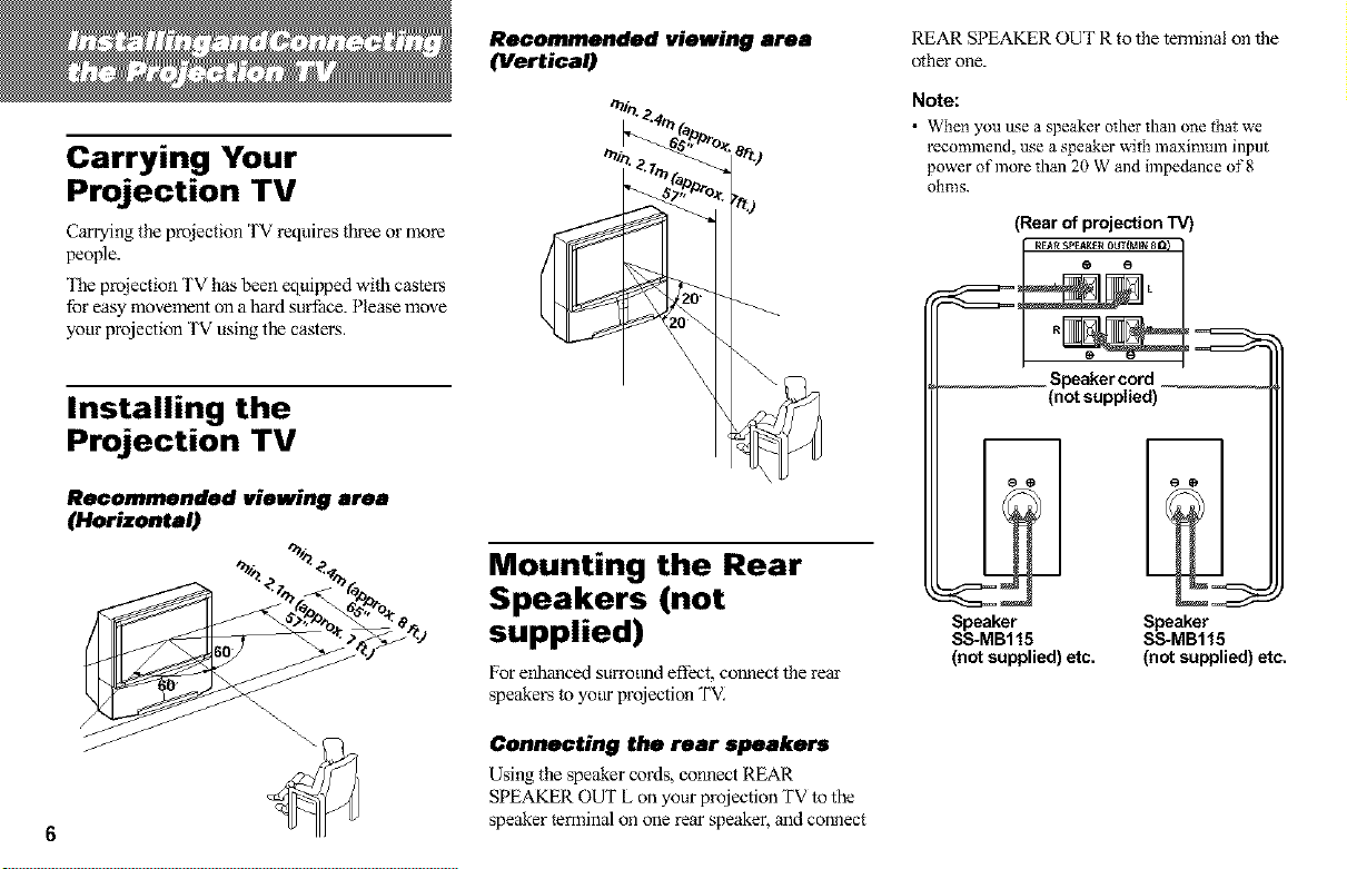
Recommended viewing area
(Horizontal)
Recommended viewing area
(Vertical)
ST,,
Mounting the Rear
Speakers (not
supplied)
For enhanced sun-otmdeffect, connect the rear
speakers to yottr projection TVI
REAR SPEAKER OUT R to the temlinal on the
o_her one.
Note:
• When you use a speaker oIher than one that we
recommend, use a speaker with maximmn input
power of more than 20 W and impedance of 8
ohms.
(Rear of projection TV)
[ REARSPEAK[_ OUT{MIN 8 Q}
Speaker cord
(not supplied)
Speaker
SS-MB115
(not supplied) etc.
Speaker
SS-MB115
(not supplied) etc.
Connecting the rear speakers
Using the speaker cords, conne_ REAR
SPEAKER OUT L on your p_e_ion TV to the
speaker terminal on one rear speaker, and connect
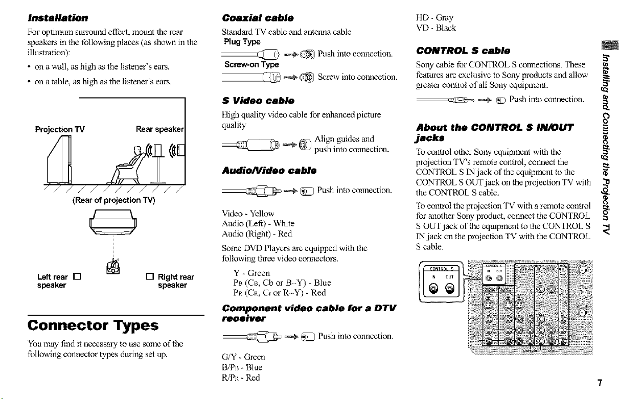
Installation
For optimum su_ou_ effect, mou_ the rear
speakers in the following places (as shown in the
illustration):
• on a wall, as high as the listener's ears.
• on a table, as high as the listener's ears.
Projection TV Rear speakel
_/////////
(Rear of projection TV)
Left rear [] [] Right rear
speaker speaker
Connector Types
You may find it necessary to use some of the
following connector types dining set up.
Coaxial cable
Standard TV cable and antenna cable
Plug Type
______ _ _ Push into connection.
Screw-on Type
_ @ Screw into connection.
S Video cable
High quality video cable for enhanced picture
quality
Align guides and
_ _0_) push into connection.
Audio/Video cable
__@ _ @ Push into connection.
Video- Yellow
Audio (Left) - White
Audio (Right) - Red
Some DVD Players are equipped with the
following three video connectors.
Y - Green
PB(CB, CborB Y)-Blue
PR(CR, C_orR Y)-Red
Component video cable for a DTV
rocalvor
--@ _ _ Push into connection.
G/Y - Green
B/PB - Blue
WPR - Red 7
HD - Gray
VD - Black
CONTROL S cable
Sony cable for CONTROL S connections. These
features are exclusive to Sony products and allow
greater control of all Sony equipment.
--_ _ @ Push into connection.
About the CONTROL S IN/OUT
jacks
_lb control other Sony equipment with the
projection TV's remote control, connect the
CONTROL S IN jack of the equipment to the
CONTROL S OUT jack on the projection TV with
the CONTROL S cable.
_15control the projection TV with a remote control
for another Sony product, connect the CONTROL
S OUT jack of the eqtfipment to the CONTROL S
INjack on the proiection TV with the CONTROL
S cable.
g-
t_
==
t_
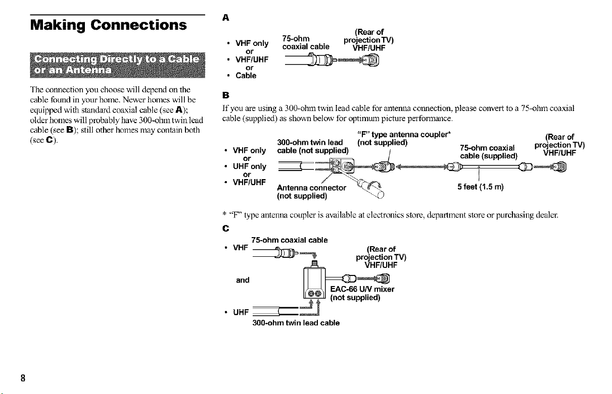
Making Connections
The connection you choose will depend on the
cable found in your home. Newer homes will be
equipped with standard coaxial cable (see A);
older homes will probably have 300-ohm twin lead
cable (see B); still other homes may contain both
(see C).
A
(Rear of
• VHF only
or
• VHF/UHF
or
• Cable
75-ohm projection TV)
coaxial cable VHF/UHF
B
If you are using a 300-ohm twin lead cable for antenna connection, please convert to a 75-ohm coaxial
cable (supplied) as shown below for optimttm picture perfolrnonce.
• VHF only cable (not supplied) 75-ohm coaxial
or cable (supplied) VHF/UHF
• UHF only
or
• VHF/UHF
F' type antenna coupler is available at electronics store, department store or purchasing dealer.
300-ohm twin lead (not supplied) projection'rV)
Antenna connector 5 feet (1.5 m)
(not supplied)
"F" type antenna coupler* (Rear of
C
75-ohm coaxial cable
• VHF __ (Rearof
and _ /nEAC_6U/V mixer
• UHF __ (not supplied)
300-ohm twin lead cable
projection TV)
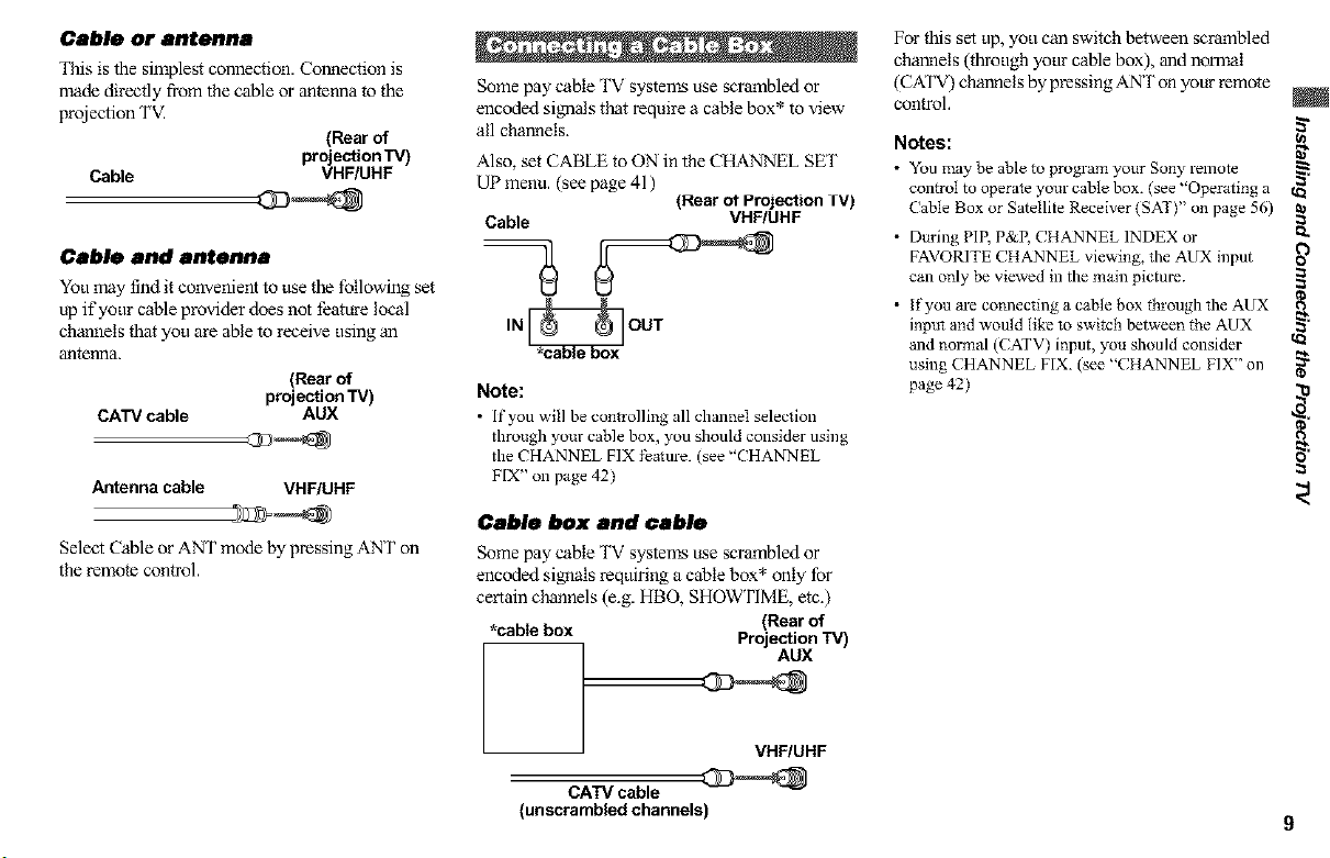
Cable or antenna
This is the simplest connection. Connection is
made directly from the cable or antenna to the
projection TV.
(Rear of
Cable VHF/UHF
projection TV)
Cable and antenna
You may find it convenient to use the following set
up if your cable provider does not feature local
channels that you are able to receive using an
antenna.
(Rear of
CATV cable AUX
Antenna cable VHF/UHF
Select Cable or ANT mode by pressing ANT on
the remote control.
projection TV)
Some pay cable TV systems use scrambled or
encoded si_aals that require a cable box* to view
all channels.
Also, set CABLE to ON in the CHANNEL SET
UP menu. (see page 41)
Cable VHF/UHF
(Rear ot Projection rv)
U
IN _ OUT
Note:
• If you will be controlling all channel selection
through your cable box, you should consider using
the CHANNEL FIX feature./see '"CHANNEL
FIX" on page 42)
Cable box and cable
Some pay cable TV systems use scrambled or
encoded signals requiring a cable box* only for
certain channels (e.g. HBO, SHOWTIME, etc.)
*cable box Projection TV)
(Rear of
AUX
For this set up, you can switch between scrambled
channels (through your cable box), and nol_al
(CATV) channels by pressing ANT on your remote
control.
Notes:
• You may be able to program your Sony relnote
control to operate your cable box. (see "Operating a
Cable Box or Satellite Receiver (SAT)" on page 56)
• During PIP, P&P, CHANNEL INDEX or
FAVORITE CHANNEL viewing, the AUX input
call only be viewed ill the main picture.
• If you are connecting a cable box through the AUX
input and would like to switch between the AUX
and normal (CATV) input, you should consider
using CHANNEL FIX. (see "CHANNEL FIX" on
page 42)
(n
g-
on
==
o_
VHF/UHF
CATV cable
(unscrambled channels) 9

Disconnectall power sources beforemakingany connections.
Attach the coaxial cable fi-om the incoming
cable connection or antenna to IN on the VCR.
2 Using a coaxial cable, connect OUT on the
VCR to VHF/UHF on the woj ection TV.
3 Using AUDIO and S VIDEO* cables, connect
AUDIO and S VIDEO OUT on the VCR to
AUDIO and S VIDEO IN on the projection TV
(White-AUDIO De'R, Red-AUDIO Right).
* If your VCR isnot equipped with S VIDEO, use
a VIDEO cable (yellow) instead of the S VIDEO
cable.
Note:
• If you are connecting a monaural VCR, connect
only the single audio output to the left (MONO)
input on the projection TV.
SVIDEO,--
(Rear of projection TV)
VIDEO
_AUDIO-L
_AUDIO-R
%,
VMC-810S/820S
(not supplied)
YC-I 5V/30V (not supplied)
2
Coaxial cable
VCR
10
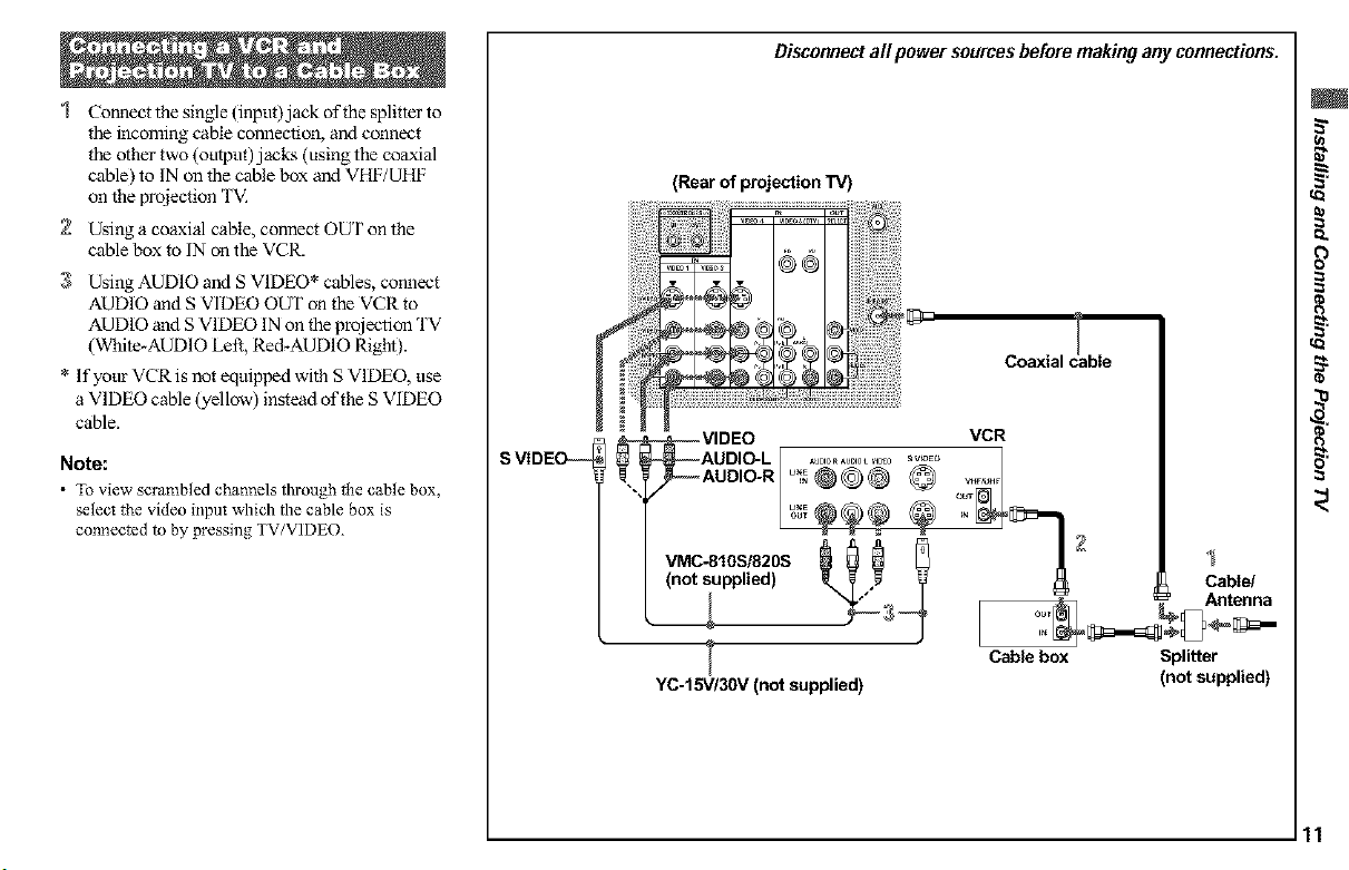
Connect the single (input)jack of the splitter to
the incoming cable connection, and connect
the other two (omput)jacks (using the coaxial
cable) to IN on the cable box and VHF/UHF
on the projection TV.
2 Using a coaxial cable, connect OUT on the
cable box to IN on the VCR.
3 Using AUDIO and S VIDEO* cables, connect
AUDIO and S VIDEO OUT on the VCR to
AUDIO and S VIDEO IN on the projection TV
(White-AUDIO Left, Red-AUDIO Right).
* Ifyour VCR is not equipped with S VIDEO, use
a VIDEO cable (yellow) instead of the S VIDEO
cable.
Note:
• To view scrambled channels through the cane box,
select the video input which the cable box is
connected to by pressing TV/VIDEO.
Disconnectall powersources beforemakingany connections.
(Rear of projection TV)
Coaxial c_able_
SVIDE_
(not supplied) _ _ _ _ _ Cable/
_,_ _ _Antenna
l Cable box Splitter
YC-15V/30V (not supplied) (not supplied)
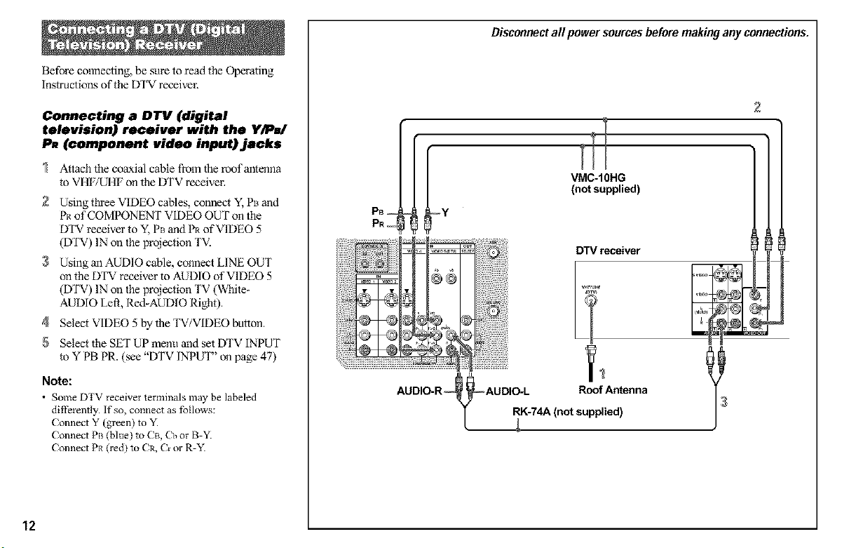
Before connectthg, be sure to read the Operating
instructions of the DTV receiver.
Connecting a DTV (digital
television) receiver with the Y/P /
P_ (component video input) jacks
Attach the coaxial cable from the roof antenna
to VHF/UHF on the DTV receiver.
2 Using three VIDEO cables, connect Y, Pl_and
l'_ of COMPONENT VIDEO OUT on the
DTV receiver to Y, PB and PI_of VIDEO 5
(DTV) IN on the projection TV.
3 Using an AUDIO cable, connect LINE OUT
on the DTV receiver to AUDIO of VIDEO 5
(DTV) IN on the projection TV (White-
AUDIO Left, Red-AUDIO Right).
4 SelectViDEO5bytheTV/ViDEObutton.
5 Select the SET UP menu and set DTV INPUT
to Y PB PR. (see "DTV INPUT" on page 47)
Note:
• Some DTV receiver terminals may be labeled
difi)rently. If so, connect as follows:
Connect Y (green) to "K
Connect PB (blue) to CB, Cb or B-YI
Connect PR (red) to Ca, Cr or R-Y.
PB--
PR--
_N
iiiiiiiiiiiiiiiiiiiii_N::&.
AUDIO-R @AUDIO-L Roof Antenna
Disconnectall power sources beforemakingany connections.
2
VMC-10HG
(not supplied)
IY
Dw receive_
T
RK-74A (not supplied)
J
12
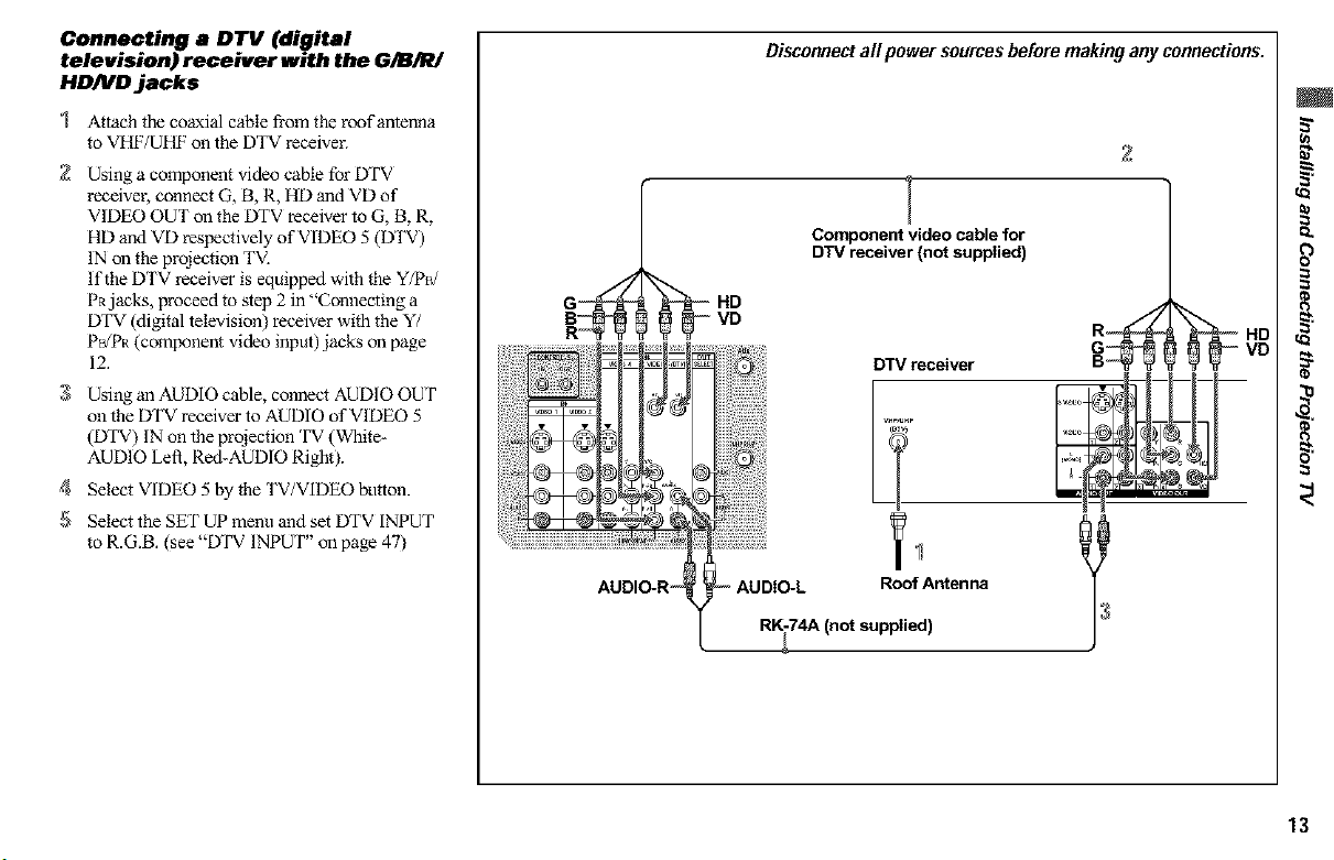
Connecting a DTV (digital
television) receiver with the G/B/R/
HDND jaeks
Attach the coaxial cable fi-om the roof antenna
to VHF/UHF oll the DTV receiver.
2 Using a component video cable for DTV
receiver, connect G, B, R, HD and VD of
VIDEO OUT on the DTV receiver to G, B, R,
HD and VD respectively of VIDEO 5 (DTV)
IN on the projection TV.
If the DTV receiver is equipped with the Y/P_/
PRjacks, proceed to step 2 in "Connecting a
DTV (digital television) receiver with the Y/
P_gPR (component video input) jacks on page
12.
3 Using an AUDIO cable, connect AUDIO OUT
on the DTV receiver to AUDIO of VIDEO 5
(DTV) IN on the projection TV (Whiter
AUDIO Left, Re&AUDIO Right).
4 Select VIDEO 5 by the TV/VIDEO button.
5 Select the SET UP menu and set DTV INPUT
to R.G.B. (see "DTV INPUT" on page 47)
H _ t@
AUDIO-R _ _ AUDIO-L
Disconnectall powersources beforemakingany connections.
2
Component video cable for
DTV receiver (not supplied)
VD
DTV receiver
RK-74A (not supplied)
F!o_Antenna I
VD
13
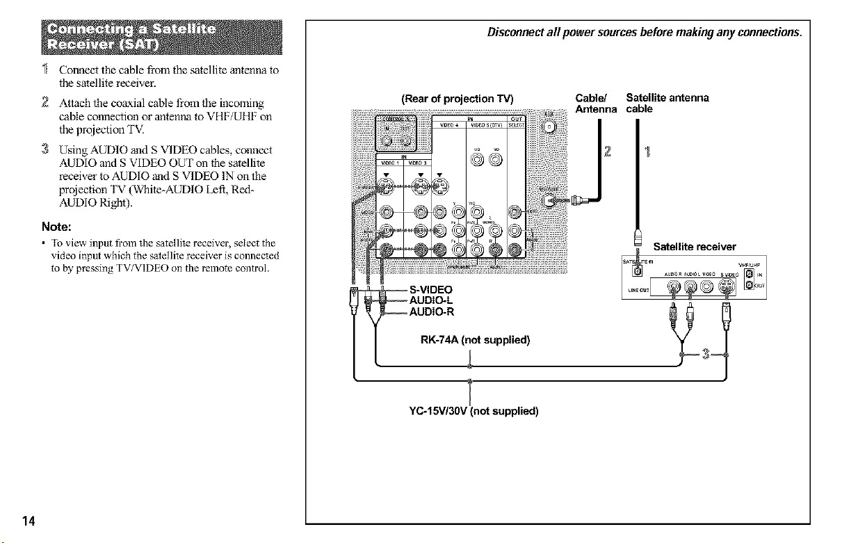
Connect the cable from the satellite antenna to
the satellite receiver.
2 Attach the coaxial cable from the incoming
cable connection or antenna to VHF/UHF on
the projection TV.
3 Using AUDIO and S VIDEO cables, connect
AUDIO and S VIDEO OUT on the satellite
receiver to AUDIO and S VIDEO IN on the
projection TV (White-AUDIO Left, Red_
AUDIO Right).
Note:
• lb view input fi'om the satellite receiver, select the
video input which the satellite receiver is connected
to by pressing TV/VIDEO on the remote control.
(Rear of projection TV)
_ S-VIDEO
AUDIO-R
RK-74A ( ot supplied)
AUDIO-L _
YC-I 5v/a0v (not supplied)
Disconnectall power sources beforemakingany connections.
Cable/ Satellite antenna
Antenna cable
j
I
14
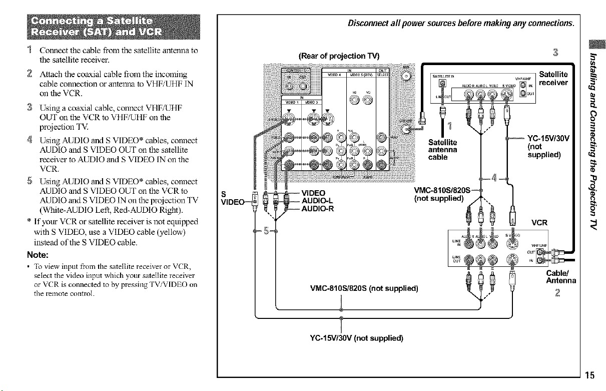
Disconnectall powersources beforemakingany connections.
Connect the cable from the satellite antenna to
the satellite receiveE
2 Attach the coaxial cable from the incoming
cable connection or antenna to VHF/UHF IN
on the VCR.
3 Using a coaxial cable, connect VHF/UHF
OUT on the VCR to VHF/UHF on the
projection TV.
4 Using AUDIO and S VIDEO* cables, connect
AUDIO and S VIDEO OUT on the satellite
receiver to AUDIO and S VIDEO IN on the
VCR.
5 Using AUDIO and S VIDEO* cables, connect
AUDIO and S VIDEO OUT on the VCR to
AUDIO and S VIDEO IN on the projection TV
(White-AUDIO Left, Red-AUDIO Right).
* If your VCR or satellite receiver is not equipped
with S VIDEO, use a VIDEO cable (yellow)
instead of the S VIDEO cable.
Note:
• To view input fi'om the satellite receiver or VCR,
selecl the video input which your satellite receiver
or VCR is connected to by pressing TV/VIDEO on
the remole control.
S
VIDEO_
VMC-810S/820S (not supplied)
1,
T
YC-15V/30V (not supplied)
Satellite
antenna
cable
VMC-810S/820S --
(not supplied)
3
-- YC-15V/30V
(not
supplied)
VCR
Antenna
2
l Cable/
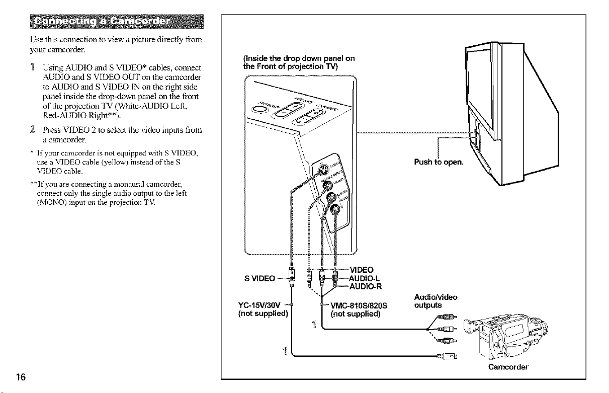
Use this connection to view a picture directly from
your camcorder.
Using AUDIO and S VIDEO* cables, connect
AUDIO and S VIDEO OUT on the camcorder
to AUDIO and S VIDEO IN on the light side
panel inside the tirOl>down panel on the front
of the projection TV (White-AUDIO left,
Red-AUDIO Right**).
2 Press VIDEO 2 to select the video inputs from
a camcordeE
* If yore" camcorder is not equipped with S VIDEO,
use a VIDEO cable (yellow) instead of the S
VIDEO cable.
**If you are connecting a monaural camcorder,
connect only the single audio output to the left
(MONO) input on the prqiection TV]
(inside the drop down panel on
the Front of projection TV)
--
Push to open.
16
SVIDEO ,--
YC-15V/30V "_
(not supplied]
AUDIO-L
VIDEO
AUDIO-R
- VMC-810S/820S
(not supplied)
Audio/video
outputs
Camcorder
 Loading...