

Page 1

3-867-651-11 (2)
Color Reàr Video Projector
Operating Instructions
KP-53XBR300
KP-61XBR300
© 1999 Sony Corporation
1^
10801 Capable
Digital Reality Creation
Multi Image Driver
FLASH FOCUS
Page 2

WARNING
To prevent fire or shock
hazard, do not expose the TV
to rain or moisture.
CAUTION
RISK OF ELECTRIC SHOCK
DO NOT OPEN
ATTENTION
RISQUE DE CHOC ELECTRIQUE,
NE PAS OUVRIR
PRECAUCION
RIESGO DE CHOQUE ELECTRICO
NO ABRIR
CAUTION : TO REDUCE THE RISK OF ELECTRIC SHOCK.
DO NOT REMOVE COVER (OR BACK).
NO USER-SERVICEABLE PARTS INSIDE.
REFER SERVICING TO QUALIFIED SERVICE PERSONNEL-
This symbol is intended to alert the user to the
presence of uninsulated “dangerous voltage”
within the product’s enclosure that may be of
sufficient magnitude to constitute a risk of
electric shock to persons.
This symbol is intended to alert the user to the
presence of important operating and
maintenance (servicing) instructions in the
literature accompanying the appliance.
CAUTION
To prevent electric shock, do not use this polarized AC
plug with an extension cord, receptacle or other outlet
unless the blades can be fully inserted to prevent blade
exposure.
CAUTION
Wlien using TV games, computers, and similar products
with your projection TV. keep the brightness and contrast
functions at low settings. If a fixed (non-moving) pattern is
left on the screen for long periods of time especially at a
high brightness or contrast setting, the image can be
permanently imprinted onto the screen. These types of
imprints are not covered by your warranty because they
are the result of misuse.
Note on Caption Vision
This television receiver provides display of television
closed captioning in accordance with §15.119 of the FCC
rules.
Note on convergence adjustment
Before you use your projection TV, make sure to adjust
convergence. For details, see page 22.
Note to CATV system installer
This reminder is provided to cal! the CATV system
installer’s attention to Article 820-40 of the NEC that
provides guidelines for proper grounding and, in particular,
specifies that the cable ground shall be connected to the
grounding system of the building, as close to the point of
cable entry as practical.
Use of this television receiver for other than private
viewing of programs broadcast on UHF or VHF or
transmitted by cable companies for the use of the general
public may require authorization from the broadcaster/
cable company and/or program owner.
NOTIFICATION
This equipment has been tested and found to comply with
the limits for a Class B digital device pursuant to Part 15 of
the FCC Rules. These limits are designed to provide
reasonable protection against harmful Interference In a
residential installation. This equipment generates, uses,
and can radiate radio frequency energy and, if not
installed and used in accordance with the instructions,
may cause harmful interference with radio
communications. However, there is no guarantee that
interference will not occur in a particular installation. If this
equipment does cause harmful interference to radio or
television reception, which can be determined by turning
the equipment off and on, the user is encouraged to try to
correct the interference by one or more of the following
measures;
■ Reorient oi relocate the receiving antennas.
Increase the separation between the equipment and
receiver.
' Connect the equipment into an outlet on a circuit
different from (hat to which the receiver is connected.
' Consult the dealer or an experienced radio-TV
technician for help.
You are cautioned that any changes or modifications
not expressly approved in this manual could void your
authority to operate this equipment.
This document is for the remote control RM-Y902
MODELS: KP-53XBR300, KP-61XBR300
Please keep this notice with the instruction manual.
As an ENERGY STAR Partner, Sony
Corporation has determined that this
product meets the ENERGY STAR
guidelines for energy efficiency.
ATTENTION
Pour prévenir les chocs électriques, ne pas utiliser cette
fiche polarisée avec un prolongateur, une prise de courant
ou une autre sortie de courant, sauf si les lames peuvent
tre insérées à fond sans en laisser aucune partie à
découvert.
Owner’s Record
The model and serial numbers are located at the rear of
the projection TV, below the Sony logo, on the sticker, and
also on the TV box (white label). Record these numbers in
the spaces provided below. Refer to them whenever you
call upon your Sony dealer regarding this product.
Model No._
Serial No._
Page 3
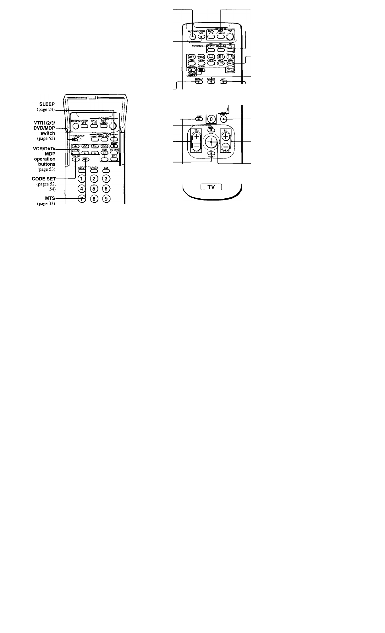
Remote Control
In the instructions that
follow, we will refer to
the buttons on your remote control.
Keep this flap unfolded and use this page for
reference.
For (I ih’taiU’J exphmation of most hiilloiis. see
"Wutohin); the T\'" on 23.
MUTING
(p.icc
SYSTEM OFF*
TV/DBS/
PICTURE
MODE
MODE-^
page .^2) [
(page
GUIDE/
(pages 24, .Sa)
DISPLAY
(page 24)
JUMP—I
(page 23)
MENU
(page 31)
VOL +/-
(page 23)
RESET
(pages 33, 34)
© ® @
© © ©
© ® ©
SONY
POWER
(p.iges 23. .s4'i
I—
FUNCTION
(pages 23. ,34)
PIP/P&P/
CHANNEL INDEX
(pages 26 - 30)
TV/VIDEO
(page 24)
ANT
(page 23)
0-9 buttons
(page 23)
ENTER
(pages 23, 52)
CH+/-
(page 23)
Joystick
(page 20)
Getting to know the buttons on the remote control
Names of the hiitlons on the remote
control are presented in different
colors to represent the a\ailahle
functions.
Button color
TransparenttPrcss to select the
component you want to control;
e.g. VTR (VCR)/MDP/DVD
Player, DBS (Direct Broadcast
Satellite)/CABLE, or projection
TV.
GreentButtons relevant to power
operations, like turning the
projection TV, DBS/CABLE, or
VTR (VCR)/MDP/DVD Player
on or off
Label color
White:TV/VTR (VCR)/MDP/
DVD Player/DBS (Direct
Broadcast Satellitej/CABLE
operation buttons
YellowtPIP, P&P, and CHANNEL
INDEX operation buttons
BluetDBS operation buttons
PinktDVD Player operation
buttons
* The SYSTEM OFF button does not function with this projection TV.
Page 4

Table of Contents
Before You Begin
Welcome!
Using this Manual
Precautions
Installing and Connecting
the Projection TV
Carrying Your Projection TV
Installing the Projection TV
Mounting the Supplied Rear Speakers. .
Connector Types
Making Connections
..............................
................
...........................
.........................
............................
...............................................
.........................................
Connecting Directly to a Cable or an
Antenna
....................................................
Connecting a Cable Box
Connecting an Antenna/Cable TV
System to a VCR
Connecting a VCR and Projection
TV to a Cable Box
Connecting a DTV (Digital Television)
Receiver .....................................................9
Connecting a DBS (Direct Broadcast
Satellite) Receiver
Connecting a DBS (Direct Broadcast
Satellite) Receiver and VCR...................12
..............................
........................................
......................................
....................................
Connecting a Canicorder............................13
Connecting Two VCRs tor Tape
Editing
..................................................
Connecting a DVD Player With S Video
or Composite Video Output
1
2
2
Connectors
Connecting a DVD Player With
Component Video Output
Connectors
Connecting an AV Receiver .... . . .17
Connecting an Audio System ....
Connecting an Amplifier That Supports
........................................
........................................
Dolby Pro Logic* Decoder . .. . . .19
Basic Set Up
Using the Remote Control
Setting Up the Projection TV Automatically 21
Adjusting the Convergence Automatically
(FLASH FOCUS)..................................................22
7
Using Your New Projection
TV
8
Watching the TV.......................................................23
Watching Digital TV.................................................25
Watching Two Programs at One Time
11
— PIP............................................................
Watching Two Programs at One Time — P&P
(Twin View™).......................................................27
........................................
14
. . . 15
. . .16
. . .18
20
.26
Usine CHANNEL INDEX...................................29
Adjusting Your SET UP
(menus)
Learning Menu Selection.........................................31
B Using the VIDEO Menu
Using the AUDIO Menu
Adjusting the Speaker Volume for
Customized Surround Mode
© Using the TIMER Menu
® Using the CHANNEL SET UP Menu. . . 36
Setting and Selecting FAVORITE
CHANNEL
© Using the SET UP Menu.......................................39
Using the PARENTAL CONTROL Feature 42
............................................................
Setting FAVORITE CHANNEL
manually ...................................................38
Resetting FAVORITE CHANNEL
choices........................................................38
Using FAVORITE CHANNEL .... 39
Activating the PARENTAL CONTROL
feature
........................................................
Selecting a Custom Rating in U.S.A. 44
Selecting a Custom Rating in Canada 47
Changing the Password
.......................................
.....................................
..................
......................................
................................
34
32
33
35
38
42
48
Page 5

What tlio Ratings Mcati.........................................49
Rating in U.S.A
Ratings iti Canada..........................................50
..........................................
Additional Operations
Operating Video Equipment.....................................52
Setting the Manufacturer's Code..................52
Operating video equipment...........................53
Operating a Cable Box or DBS Receiver... .54
Setting the Manufacturer's Code..................54
Operating a cable box or DBS receiver 54
Additional Information
Troubleshooting .........................................................55
Specifications
Index
Manufactured under license from Dolby Laboratories
Licensing Corporation. Additionally licensed under
Canadian patent number 1,037,877. “Dolby,” the double-D
symbol □□ and “Pro Logic” are trademarks of Dolby
Laboratories Licensing Corporation
..............................................................
............................................................................
Before You Begin
49
Welcome!
Thank you for purchasing tlie Sony Color Rear
Video Projection TV. This manual is for models
KP-5.3XBR,3(X) and KP-61XBR.^(X).
Model KP-53XBR.3(X) is used for illustration
purposes.
The features you will enjoy include:
• "lOSOi Capable," enabling you to receive the 1080i,
480p and 480i digital TV formats (except for 720p
format). By using the VIDEO 5 (DTV) IN jacks,
you can connect a DTV (digital television) receiver
to view DTV programs.
The VIDEO .8 (DTV) IN jacks also function as R/G/
B connectors with SYNC signal (HD/VD), but are
58
59
not compatible with a computer’s 5BNC video
output connectors.
• PARENTAL CONTROL, enabling you to block
programs that are unsuitable for your children.
• DRC (Digital Reality Creation), a technology 7jfO
unique to Sony, allowing you to obtain a finer, more
detailed picture with four-times higher density than
the conventional NTSC picture, (not available for
input from the VIDEO 5 (DTV) IN jacks)
• MID (Multi Image Driver), a newly developed
device, allowing you to enjoy the following features
and, at the same time, to use your projection TV
easily, (not available for input from the VIDEO 5
(DTV) IN jacks)
Picture N Picture (P.kPi with /oom-in function
( Twin N'icw''''“)
- - Picluie-in-Picturc tPlP)
CH.ANNEL INDEX, allowing you to view and
clioosc from Iweb e programs
— 1-AVORITE CH.ANNEL, allov\ ing you to view
and choiise from eight of your favorite channels
PLASH FOCUS, allowing you to adjust
convergence automatically.
Two Y/Pr/Pr inputs for DVD Player connection
(480p format capability is on the VIDEO 5 (DTV)
IN jacks).
Four AUDIO/VIDEO/S VIDEO inputs.
OD
n
c
GD
3*
Page 6

Using this Manual
W'c avomiuciKl lluil sou carofulls res less liucoiilcms of ills' follow ing four ss-s'tions in Ills' Ol sis'l
pros isis'si 10 s'lisurs' Ilinl ysHi fully unsls'rsUlllsl ills'
operation of s'our noss' projes'tion TV.
1 Installing and Connecting the Projection TV
This section guides you through your initial set
up. It shoss's you hosv to install your projection
TV, to connect your nesv components and to
connect to the antenna and cable.
2 Basic Setup
This section teaches you the basic skills needed
to operate your new projection TV, including
Easy Set Up. It shows you how to operate the
remote control's special functions.
3 Using Your New Projection TV
This section shows you how to begin using
your new projection TV. It shows you how’ to
use your remote control’s features.
4 Adjusting Your Set Up (menus)
This section teaches you how to access on
screen menus and adjust your projection TV’s
settings.
Instructions in this manual are written for the remote
control. Similar controls may be found on the
projection TV console.
Precautions
Safety
• Operate the projeetion TV onh on 110 V AC.
• The plug is designed. Гог sat'ety punx'ses. to tit into
the wall outlet only one way. It you are unable to
insert the plug fully into the outlet, eoniaei your
dealer.
• If any liquid or solid object should fall inside the
cabinet, unplug the projection TV immediately and
have it checked by qualified service personnel
before operating it further.
• If you will not be using the projection TV for
several days, disconnect the power by pulling the
plug itself. Never pull on the cord.
For details concerning safety precautions, see the
supplied leaflet "¡MPORTANT SAFEGUARDS."
Note on cleaning
Clean the cabinet of the projection TV with a dry
soft cloth. To remove dust from the screen, wipe it
gently with a soft cloth. Stubborn stains may be
removed with a cloth slightly dampened with
solution of mild soap and warm water. Never use
strong solvents such as thinner or benzine for
cleaning.
If the picture becomes dark after using the
projection TV for a long period of time, it may be
necessary to clean the inside of the projection TV.
Consult qualified service personnel.
Installing
• To picNOiii iniom.il boat buildup, do nol bUvk the
vontilation openings.
• Do nol install the projection TV in a hot or humid
place, or in a place subject to excessive dust or
mechanical vibration.
• Avoid operating the projection TV at temperature
below .S"C (4I "F).
• If the projection TV is transported directly from a
cold to a warm location, or if the room temperature
changes suddenly, the picture may be blurred or
show poor color. In this ca.se. plea.se wail a few
hours to let the moisture evaporate before turning
on the projection TV.
• To obtain the best picture, do not expose the screen
to direct illumination or direct sunlight. It is
recommended to use spot lighting directed down
from the ceiling or to cover the windows that face
the screen with opaque drapery. It is desirable to
install the projection TV in a room where the floor
and walls are not of a reflective material.
Page 7
Installing and Connecting
the Projection TV
Carrying Your
Projection TV
Carrying the projection TV requires three or more
people.
The projection TV has been equipped with casters
for easy movement on a hard surface. Please move
your projection TV using the casters.
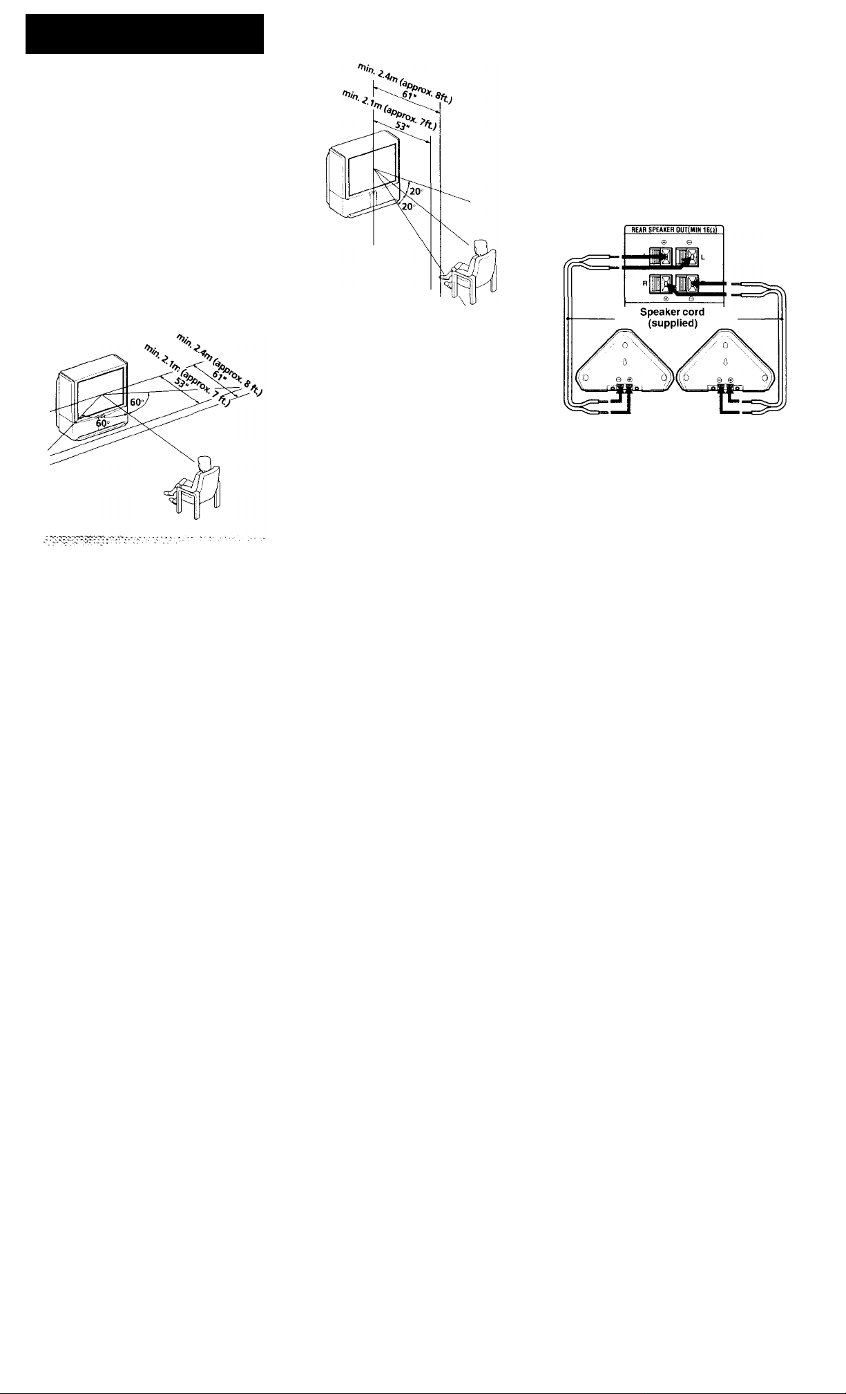
Installing the
Projection TV
Recommended viewing area (Horizontai)
Recommended viewing area
(Vertical)
Mounting the Supplied Rear Speakers
For enhanced surround effect, connect the supplied
rear speakers to your projection TV.
Connecting the rear speakers
Using the supplied speaker cords, connect REAR
SPEAKER OUT L on your projection TV to the
speaker terminal on one rear speaker, and connect
REAR SPEAKER OUT R to the terminal on the
other one.
(Rear of projection TV)
Speaker (supplied) Speaker (supplied)
3
(A
3
<Q
Q)
3
Q.
O
0
3
3
(D
r>
<Q
3
(b
1
o
o*
3
(continued)
Page 8

Installation
I V'i'optinuim suiTouiul olToi.'l. nioiml the R\ir
s|X';ikcrs in Ihc lollinving phiei’s (¡is shown in the
illnstratloni:
• on a wall, a little liighoi or IowlM' than the
listener's ears.
• on a table, a little lower than the listener's ears.
• at the eorner where the wall ami eeilinu tiieet.
Connector Types
"Vou nuiv linJ il noccs.s;ir> io u.'^o some ihe
follow ine connector types during set up.
Coaxial cable
Standard T'V cable and antenna cable
Plug Type
Push into connection.
Screw-on Type
Screw into connection.
5 Video cable
High quality video cable for enhanced picture
quality
^
----------
Pa . ^ Align guides and
push into connection.
Composite video cable for a DTV receiver
Push into connection.
G/Y - Green
B/Ph - Blue
R/Pr - Red
HD - Gras
VD - Black
CONTROL S cable
Sony cable for CONTROL S connections. These
features are exclusive to Sony products and allow
greater control of all Sony equipment.
— c:r7~T^ —♦ (57) Push into connection.
JZ
Left rear ^ speaker
Note;
• Match the colors of the speaker cords and the
terminals. If the colors are reversed, sound will be
distorted.
^ Right rear
speaker
Audio/Video cable
♦ connection.
Video - Yellow
Audio (Left) - White
Audio (Right) - Red
Some DVD Players are equipped with the
following three video connectors.
Y s Green
Pb (Cb, Cb or B-Y) - Blue
Pr (Cr, Cr or R-Y) - Red
Page 9
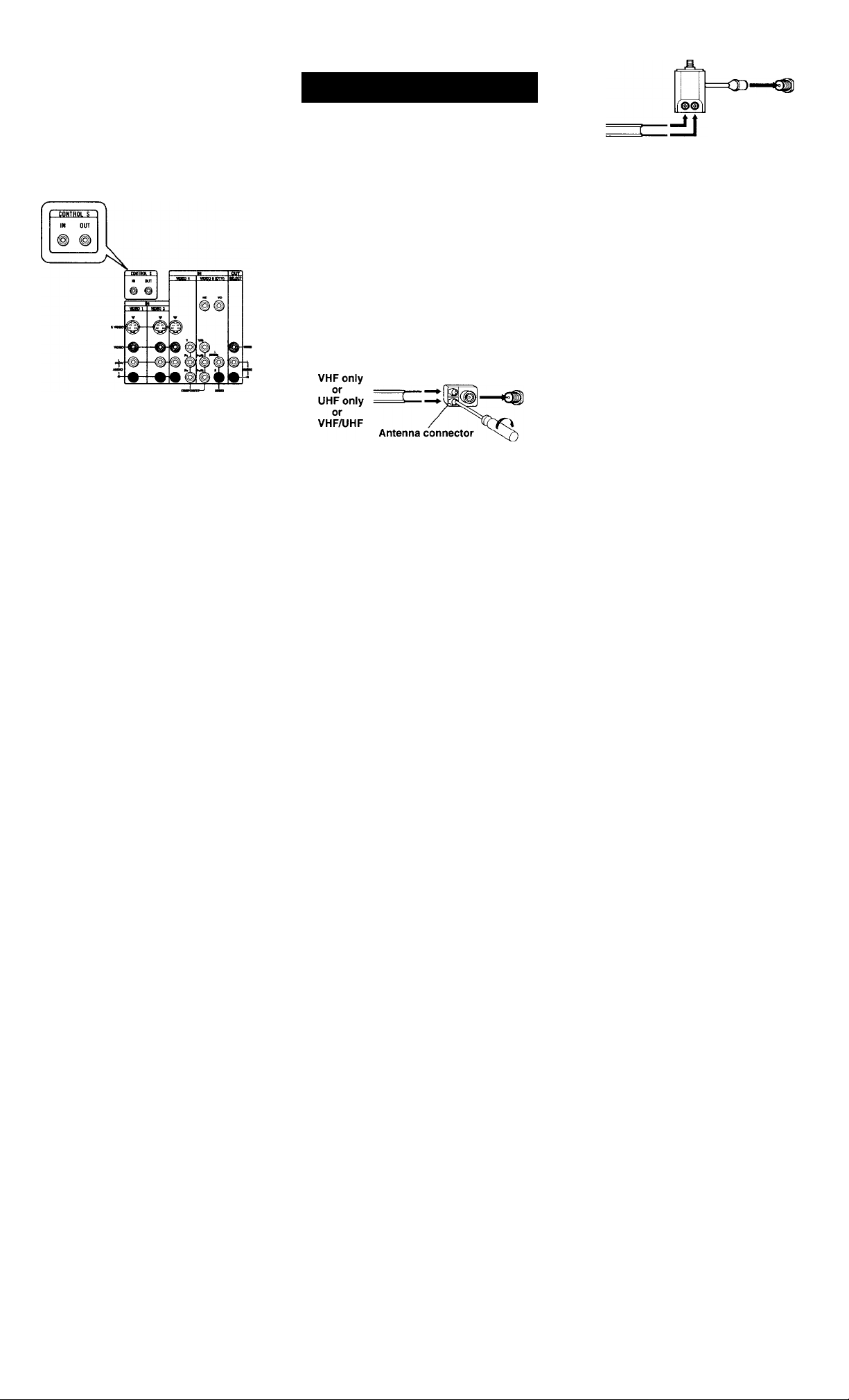
About the CONTROL S IN/OUT
jacks
To L'onlrol otlicr Sony oquipiiK'iU \\ itli llic
projection TV's rcinotc control, connect the
CONTROL S IN jack of the equipment to the
CONTROL S OUT jack on the projection TV with
the CONTROL S cable.
To control the projection TV with a retiiotc control
for another Sony product, connect the CONTROL
S OUT jack of the equipment to the CONTROL S
IN jack on the projection TV with the CONTROL
S cable.
Making Connections
Connecting Directly to a Cable
or an Antenna
The connection you choose will depend on the
cable found in your home. Newer homes will be
equipped with standard coaxial cable (see
older homes will probably have 3(K)-ohm twin lead
cable (see
B); still other homes may contain both
(see C).
VHFonly
or
VHF/UHF
or
Cable
75-ohm
coaxial cable
B
300-ohm twin
lead cable
A);
(Rear of
projection TV)
VHF/UHF
(Rear
ofprojection TV)
VHF/UHF
75-ohm coaxial cable
and
UHF
300-ohm twin lead cable
(Rear of
projection
TV)
EAC-66 U/V mixer
(not supplied)
Cable or antenna
This is the simplest connection. Connection is
made directly from the cable or antenna to the
projection TV.
(Rear of projection TV)
Cable
VHF/UHF
Cable and antenna
You may find it convenient to use the following set
up if your cable provider does not feature local
channels that you are able to receive using an
antenna.
(Rear of
projection TV)
CATV cable
AUX
:s
(A
:3
(Q
fit
:3
a
o
o
:3
3
(b
o
3
<D
<D*
O
O’
3
Antenna cable
VHF/UHF
dE
Select Cable or ANT mode by pressing ANT on
the remote control.
(continued) g
Page 10

Connecting a Cable Box
Sonic pay cable I'V systems use scrambled or
eiicrxied signals that require a cable box* to view
all channels.
Also, set CABLH to ON in the CHANNEL SET
UP menu, (see page .'^7)
Cable VHFAJHF
IN
*cable box
Note:
• If you will be controlling all channel selection
through your cable box, you should consider using
the CHANNEL FIX feature, (see "CHANNEL
FIX” on page 37)
Cable box and cable
Some pay cable TV systems use scrambled or
encoded signals requiring a cable box* only for
certain channels (e.g. HBO, SHOWTIME, etc.)
*cable box
(Rear of Projection TV)
OUT
(Rear of Projection TV)
AUX
Lor this set up, \ ou can switch between scrambled
channels (through your cable box), and normal
(C.VrV) channels by pressing .ANT on your remote
control.
Notes:
• You may be able to program your Sony remote
control to operate your cable box. (see "Operating a
Cable Box or DBS Receiver" on page .34)
• During PIP. P&P CHANNEL INDEX or
FAVORITE CHANNEL viewing, the AUX input
can only be viewed in the main picture.
• If you are connecting a cable box through the AUX
input and would like to switch between the AUX
and normal (CATV) input, you should consider
using CHANNEL FIX. (.see "CHANNEL FIX" on
page 37)
CATV cable
(unscrambled channels)
VHFAJHF
Page 11
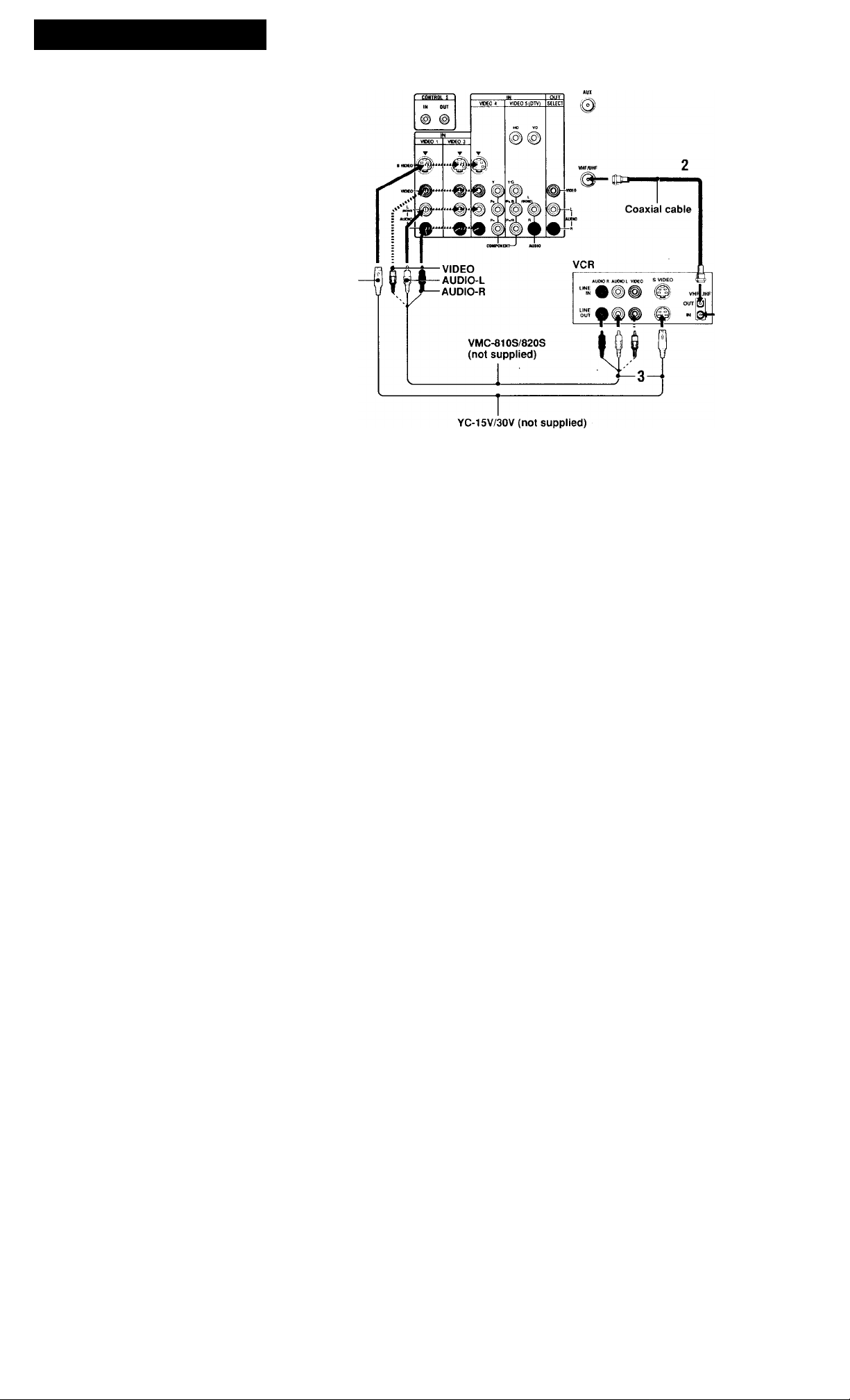
Connecting an Antenna/Cable
TV System to a VCR
Disconnect all power sources before making any connections.
1 ,'\tlacli the coaxial cable from the incoming
cable connection or antenna to IN on the \’CR.
2 Using a coaxial cable, connect OUT on the
VCR to VHF/UHF on the projection TV.
3 Using AUDIO and S VIDEO* cables, connect
AUDIO and S VIDEO OUT on the VCR to
AUDIO and S VIDEO IN on the projection TV
(White-AUDIO Left. Red-AUDIO Right).
* If your VCR is not equipped with S VIDEO, use
a VIDEO cable (yellow) instead of the S VIDEO
cable.
Note:
• If you are connecting a monaural VCR, connect
only the single audio output to the left (MONO)
input on the projection TV.
S VIDEO
(Rear of projection TV)
Cable/
Antenna
3
(0
3
<Q
Hi
3
Q.
O
o
3
3
<D
0
1
I
<D
o
o‘
a
Page 12
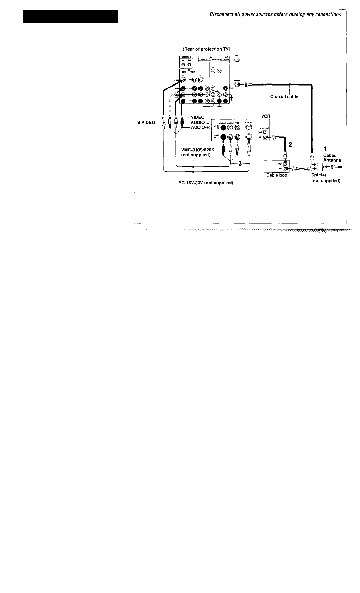
Connecting a VCR and
Projection TV to a Cable Box
1 Conno.1 llic single (input) iaek ol the splitter to
the ineoining enhie conneetion. .ind eonneet
the other two (ompnt) jaeks (using the eoaxial
eahle) to IN on the eable box and VHF/UHF
on the projeetion TV.
2 L’sing a coaxial cable, connect OUT on the
cable box to IN on the VCR.
3 Using AUDIO and S VIDEO* cables, connect
AUDIO and S VIDEO OUT on the VCR to
AUDIO and S VIDEO IN on the projection TV
(White-AUDIO Left, Red-AUDIO Right).
* If your VCR is not equipped with S VIDEO, use
a VIDEO cable (yellow) instead of the S VIDEO
cable.
Note;
• To view scrambled channels through the cable box.
select the video input which the cable box is
connected to by pressing TVA^IDEO.
Page 13
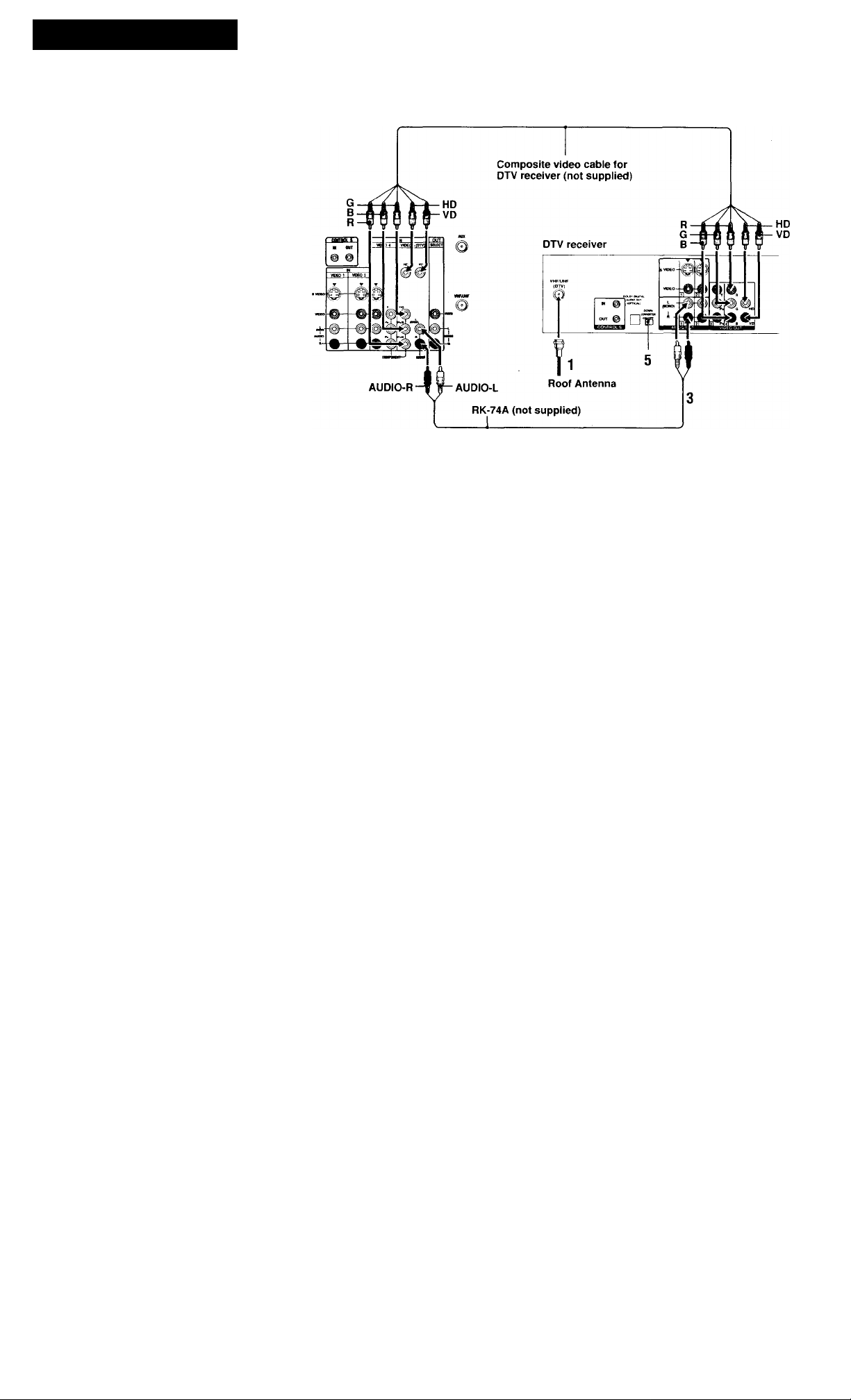
Connecting a DTV (Digital
Television) Receiver
Disconnect all power sources before making any connections.
Bct'orc connecting, ho sure to read the Oix'raling
Instructions ol the DTV recei\cr.
Connecting a DTV (digital
television) receiver with the GIB/RJ
HD/VD jacks
1 Attach the coaxial cable from the roof antenna
to VHF/UHF on the DTV receiver.
2 Using a composite video cable for DTV
receiver, connect G, B, R. HD and VD of
VIDEO OUT on the DTV receiver to G. B. R,
HD and VD respectively of VIDEO 5 (DTV)
IN on the projection TV.
If HD and VD outputs on the DTV receiver are
not available, proceed to step 2 in “Connecting
a DTV receiver with the Y/Pb/Pr (component
video input) jacks” on page 10.
3 Using an AUDIO cable, connect AUDIO OUT
on the DTV receiver to AUDIO of VIDEO 5
(DTV) IN on the projection TV (WhiteAUDIO Left, Red-AUDIO Right).
4 Select VIDEO by the TVA'IDEO button.
5 Select the SET UP menu and set DTV INPUT
to R.G.B. (see “DTV INPUT” on page 42).
Note:
• Some DTV receivers may have a DOWN
CONVERTER ON/OFF switch. This switch should
be set to OFF.
(continued)
<Q
I
3
0)
3
Q.
?
3
3
0
3
1
o
o*
3
*
Page 14
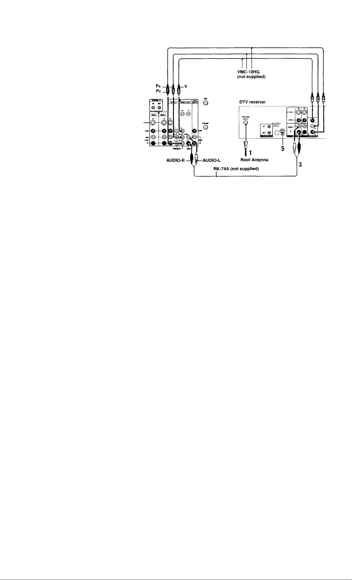
Connecting a DTV (digital
television) receiver with the Y/Pb/
Pr (component video input) jacks
1 Atladi ll>c coaxial cahlo IVom Ihc root'antonna
to \’H1-/UHI-on the irrv receiver.
2 Lisiiig three VIDHO cables, connect 'i. Pb and
Pr of component VIDEO OUT on the
DTV receix er ti> Pn and Pr of VIDEO ii
(DTV) IN on the projection TV.
3 Using an AUDIO cable, connect LINE OlIT
on the DTV receiver to AUDIO of VIDEO 5
(DTV) IN on the projection TV (White-
AUDIO Left, Red-AUDIO Right).
4 Select VIDEO 5 by the TVA'IDEO button.
5 Select the SET UP menu and set DTV INPUT
to Y PB PR. (.see “DTV INPUT" on page 42)
Notes:
• Some DTV receivers may have a DOWN
CONVERTER ON/OFF switch. This switch should
be set to OFF.
• Some DTV receiver terminals may be labeled
differently. If so, connect as follows:
Connect Y (green) to Y.
Connect Pb (blue) to Cb, Cb or B-Y.
Connect Pr (red) to Cr, Cr or R-Y.
Disconnect all power sources before making any connections.
10
Page 15
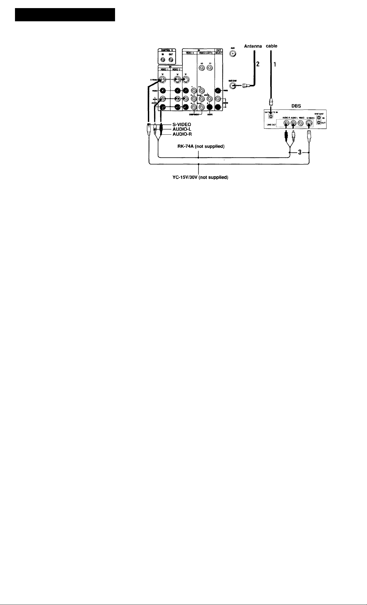
Connecting a DBS (Direct
Broadcast Satellite) Receiver
Disconnect all power sources before making any connections.
1 Connect the cable from the satellite antenna to
the DBS receiver.
2 Attach the coaxial cable from the incoming
cable connection or antenna to VHF/UHF on
the projection TV.
3 Using AUDIO and S VIDEO cables, connect
AUDIO and S VIDEO OUT on the DBS
receiver to AUDIO and S VIDEO IN on the
projection TV (White-AUDIO Left, Red-
AUDIO Right).
Note:
• To view input from the DBS, select the video input
which the DBS receiver is connected to by pressing
TV/VIDEO on the remote control.
(Rear of projection TV)
Cable/ Satellite antenna
3
0)
3
(Q
0)
3
Q.
O
o
3
3
0
3'
(Q
3
<b
1
<6*
o
o'
3
11
Page 16

Connecting a DBS (Direct
Broadcast Satellite) Receiver
and VCR
1 t'onncii llu’ fable iVom the
the salellitc roeeiver.
c. Auadi the coaxial cable iVom the incomiiis
cable contiectiott or anletitia to VHF/LIHF IN
on the VCR.
salellite anienna to
3 Using a coaxial cable, connect VHF/LIHF
OUT on the VCR to VHF7UHF on the
projection TV.
4 Using AUDIO and S VIDEO* cables, connect
AUDIO and S VIDEO OUT on the DBS
receiver to AUDIO and S VIDEO IN on the
VCR.
5 Using AUDIO and S VIDEO* cables, connect
AUDIO and S VIDEO OUT on the VCR to
AUDIO and S VIDEO IN on the projection TV
(White-AUDIO Left, Red-AUDIO Right).
* If your VCR or DBS receiver is not equipped
with S VIDEO, use a VIDEO cable (yellow)
instead of the S VIDEO cable.
Note:
• To view input from the DBS or VCR, select the
video input which your DBS receiver or VCR is
connected to by pressing TV/VIDEO on the remote
control.
Disconnect all power sources before making any connections.
(Rear of projection TV)
S
VIDEO
12
Page 17
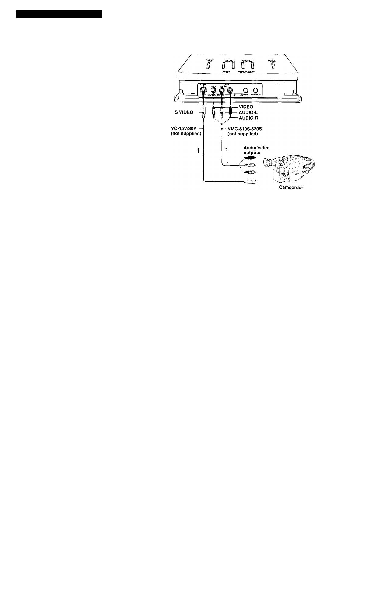
Connecting a Camcorder
L'sc this connection to \ icw a picture directly from
\ our ctniicordcr.
1 Using AUDIO and S VIDKO* cables, connect
AUDIO and S VIDEO OUT on the camcorder
to AUDIO and S VIDEO IN inside the drop-
down panel on the front of the projection TV
(White-AUDIO Left, Red-AUDIO Right**),
2 Press VIDEO 2 to select the video inputs from
a camcorder.
* If your camcorder is not equipped with S VIDEO,
use a VIDEO cable (yellow) instead of the S
VIDEO cable.
**If you are connecting a monaural camcorder,
connect only the single audio output to the left
(MONO) input on the projection TV.
Disconnect all power sources before making any connections.
(Front of projection TV)
<Q
(Q
I
3
to
3
Q.
?
3
3
CD
0
3
1
fb'
o
o'
3
‘
13
Page 18
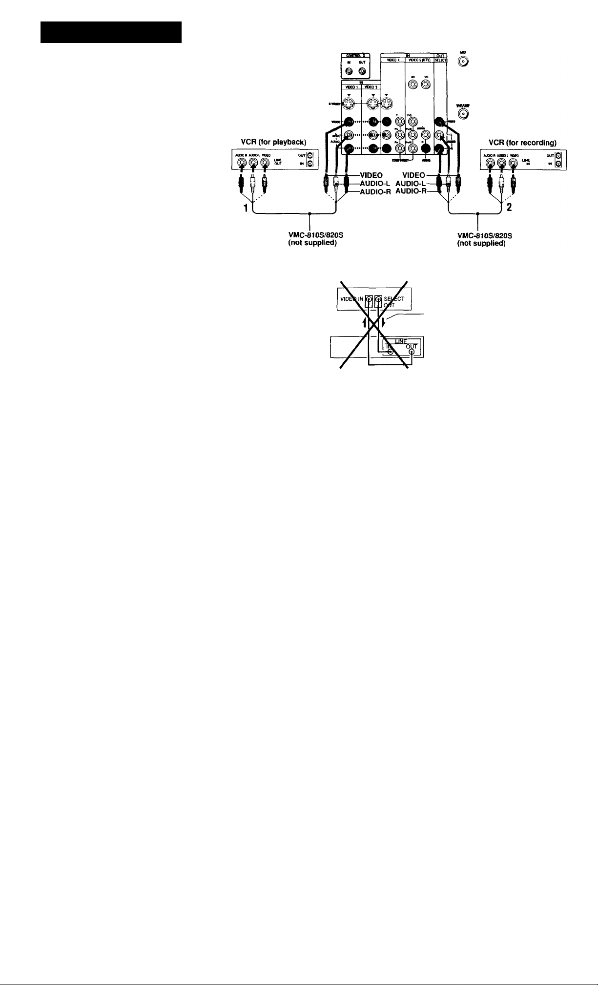
Connecting Two VCRs for
l^pe Editing
SKl.ECT OlIT gives you llic ability to use a
seeoud VCR to record a program being played by
the primary VCR or to perform tape editing and
dubbing.
1 Connect the VCR intended for playback using
the connection instructions on page 7 of this
manual.
2 Using an AUDIO/VIDEO cable, connect
AUDIO and VIDEO IN on the VCR intended
for recording to AUDIO and VIDEO OUT of
SELECT OUT on the projection TV.
Notes:
• Do not change the input signal while editing
through SELECT OUT.
• When connecting a single VCR to the projection
TV: if VCR LINE OUT is connected to VIDEO IN
on the projection TV, do not connect the SELECT
OUT on the projection TV to the VCR LINE
INPUT (see right). Doing so will cause program
interference and other viewing problems.
• You can select the output signal from SELECT
OUT from the SET UP menu, (see “SELECT
OUT’ on page 40)
Disconnect all power sources before making any connections.
(Bear of projection TV)
(Rear of projection TV)
14
- Indicates direction
of signal
Page 19
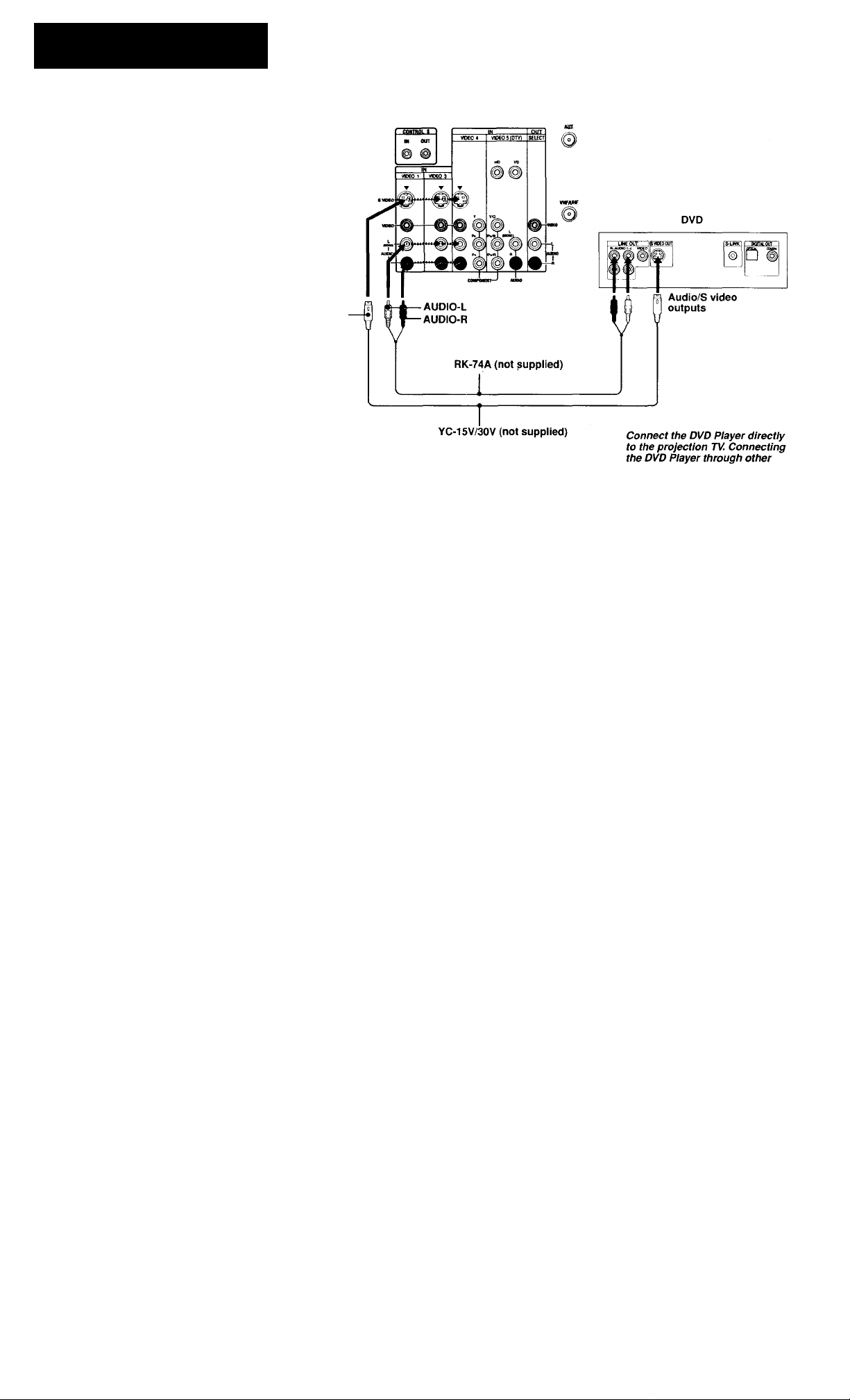
Connecting a DVD Player With
S Video or Composite Video
Output Connectors
Losing an AUDIO and S VIDHO cables, connect
AUDIO and S VIDEO IN on the piojeclion TV to
AUDIO and S VIDEO OUT on the DVD Player
(White-AUDIO Left, Red-AUDIO Right).
Note:
• Since the high quality pictures on a DVD di.sc
contain a lot of information, picture noise may
appear. In this case, adjust NR in the VIDEO menu,
(see "NR" on page 3.1)
S VIDEO
Disconnect all power sources before making any connections.
(Rear of projection TV)
(Q
3
V)
s
3'
Q)
3
o.
S'
3
3
<D
s
I
D
o'
3
video equipment wiil cause
unwanted picture noise.
15
Page 20
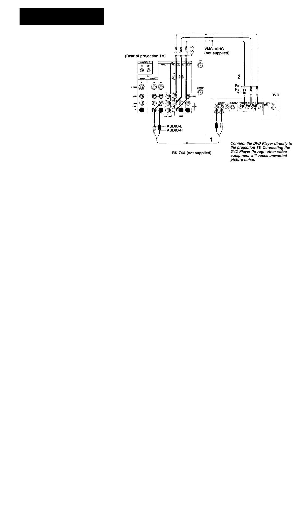
Connecting a DVD Player With
Component Video Output
Connectors
1 I'sins; an AUDIO cable, connect AUDIO R and
L of Link out on the DVD Pla\ cr to AUDIO
R and U of VIDUO 4 IN or VIDHO (DTV)
IN on the proicction TV (Wliitc-AUDIO Left.
Red-AUDIO Right).
2 Using three VIDEO cables, connect't'. Pr and
Pr of the COMPONENT VIDEO OUT on the
DVD Player to Y. Pb and Pr of VIDEO 4 IN or
VIDEO 5 (DTV) IN on the projection TV.
Notes:
• If your DVD Player has 480p format capability,
connect it to the Y. Pb and Pr of VIDEO .I (DTV)
IN on the projection TV.
• Some DVD Player terminals may be labeled
differently. If so, connect as follows;
Connect Y (green) to Y.
Connect Pb (blue) to Cb. Cb or B-Y.
Connect Pr (red) to Cr. Cr or R-Y.
• Since the high quality pictures on a DVD disc
contain a lot of information, picture noise may
appear. In this case, adjust NR in the VIDEO menu,
(see "NR” on page 33)
Disconnect all power sources before making any connections.
16
Page 21

Connecting an AV Receiver
For greater 1,'ontrol of all audio and \ idco
cquipineiil. connect an AV receiver.
1 •2Pcrfonn as described on page 7.
Disconnect all power sources before making any connections.
3
In
3 llsing a VIDEO cable, connect VIDEO of
VIDEO I IN on the projection TV to
MONITOR OV'T on the AV receiver.
4 Using an AUDIO/VIDEO cable, conned
SELECT OUT on the projection TV to VIDEO
2 IN on the AV receiver.
5 Using an AUDIO/VIDEO cable, connect the
video equipment to the AV receiver,
6 Select the SET UP menu and set SELECT
OUT to TV OUT. (see “SELECT OUT’ on
page 40)
Note:
• You may want to use CHANNEL FIX to fix your
TV’s input to the AV receiver (VIDEO 1). (see
"CHANNEL FIX” on page 37)
(Q
(Q
1
«)
3
a
?
a
0
5ji
S
(D
O
•«*
O'
o
•H
17
Page 22

Connecting an Audio System
For more d\ naniic sound, connect an audio system
to the projeetion TV.
1 Using an AUDIO eahle, eonneet AUDIO
(VAR) OL'T on the projeetion TV to one of the
unused Line inputs fe.g. Ta[V-2, AUXI, etc.)
on the stereo (White-AUDUf Left, RedAIIDIO Right).
2 Set the stereo to the ehosen Line input and use
the AUDIO menu to switch the TV's speakers
off. (see “SPEAKER" on page ,"'4)
Note;
• You ean adjust VOLUME, BASS. TREBLE and
BALANCE through the projeetion TV on AUDIO
(VAR) OUT only.
Disconnect all power sources before making any connections.
(Rear of projection TV)
wmiw^AMKOUTtiawiiQ)
i
miiwoMUWHMMoeo
18
Page 23

Connecting an Amplifier That
Supports Dolby Pro Logic
Decoder
It'you uso an amplifier with a Dolby Pro l.ogic
decoder instead of the projection TV's audio
system, you can still use the projection TV's center
speaker.
1 Using the speaker cords (supplied with the
amplifier), connect the speaker terminals on
the amplifier to CENTER SPEAKER IN +/on the projection TV.
2 Using an AUDIO cable, connect AUDIO (FIX)
OUT on the projection TV to one of the unused
Line inputs (e.g. Tape-2, AUXI. etc.) on the
amplifier (White-AUDIO Left. red-AUDIO
Right).
3 Set the amplifier to the chosen Line input and
u.se the AUDIO menu to set "SPEAKER” to
"CENTER IN” on the projection TV. (see
"SPEAKER” on page .34)
Disconnect all power sources before making any connections.
(Rear of projection TV)
3
w
<Q
Bi
3
Q.
s>
3
3
o
3
3
<b
o
o’
3
‘
19
Page 24

Bssic Set Up
Using the Remote Control
Inserting the batteries
Insert two size AA (R6) batteries (supplied) by
matehing the + and - on the batteries to the
diagram inside the remote control's battery
compartment.
Notes;
• Remove the batteries to avoid damage from
possible battery leakage whenever you anticipate
that the remote control will not be used for an
extended period.
• Handle the remote control with care. Avoid
dropping it, getting it wet, or placing it in direct
sunlight, near a heater or where the humidity is
high.
• Your remote control can be programmed to operate
most video equipment, (see “Operating Video
Equipment" on page 52)
Using the remote control joystick Adjusting sliders
W hen menu items present a slider (»—or-*- ).
© © ©
® © ®
Move
© © ®
o ® o
Select
The supplied remote control has a joystick w hich
moves the on-screen selector in eight directions. In
most cases, moving the joystick up, down, left or
right will cause the selector to move in the selected
direction.
In some cases, the selector may move in eight
directions according to the function. Pressing
down on the center of the joystick
activate the selected item.
You may also move (he joystick right to activate a
selected item. (There are some exceptions to this
option.)
(0
) will
move the joystick itp, down, left or right to adjust
the setting.
On-line help/instructions
.Several tiienu w indows w ill provide prompts and
instructions to assist vou in nar igaling through the
different fittictiotis.
20
Page 25

Setting Up the Projection TV Automatically
The AllTO SET IIP feature will allow you to set
the oil-screen language amt set all receix able
channels. The AUTO SET UP screen will appear
every time you turn on the projection TV until you
perform AUTO PROGRAM.
The AUTO SET UP feanire does nor apply for
installations that use a cable box for all channel
selection.
Yon can also set up the projection T\' manually, (see
"Using the CHANNEL SET UP Menu" on page 36)
Notes:
• Perform this function during the day. with the
antenna and/or cable properly connected, to
ensure that all available channels will be
broadcasting and receivable.
• Before you perform AUTO SET UP again, make
sure that the input from ANT (not AUX) is
selected by pressing ANT until “AUX” does not
appear next to the channel number.
• When you perform AUTO PROGRAM, your
CHANNEL FIX and ON/OFF TIMER settings
will be erased.
• When you perform AUTO PROGRAM, all the
settings in the VIDEO and AUDIO menus are
reset to the factory settings.
Using the buttons on the front panel and inside the
drop-down panel on the proicction T\ :
1 Press POWER to turn on the projection TV.
POWER
à
2 Press SET UP inside the drop-down panel.
The AUTO SET UP screen appears.
ENGLISH (CH.)
ESPAÑOL .ICH-]
FRANÇAIS[VOL >I
AUTO SET UP :1VOL-]
First please canned
Press I SET UP to exit.
3 Press CHANNEL -i- to select English,
CHANNEL - to select Spanish or VOLUME +
to select French.
the antenna.
The sereen will chance to rcllect vour choice.
- lOLLIME , -CHANNEL 4
QQ
ENGLISH
LSPANOL [CM - '
FRANÇAIS i vOl.I
AUTO SET UP
First please conned
the antenna
Press I SET UP I 0 exit
4 Press VOLUME - to continue.
CONTINUE TO
AUTO PROGRAM’
YES:[CH f;
NO iCH -
5 Press CHANNEL -i- to preset channels
automaticallv.
Ò
“AUTO PROGRAM" appears and the
projection TV starts scanning and presetting
channels automatically. While scanning, the
received channel will be displayed on the sub
screen. When all the receivable channels are
stored, the lowest numbered channel will be
displayed. If the projection TV receives cable
TV channels, CABLE is set to ON
automatically.
(CM . I
[VOL.I
(continued)
0}
CO
I
21
Page 26

To perform AUTO SET UP again
• Press Sl”V {'V inside the tirop-down panel on llie
pu'ieetion rv. and jx'rl'orm steps on paee 21.
• Pre^sO^ANNi■:l,+. CHANNPd. otA'OLUMP:
to seleel a language.
• Press XOl.UMli - to restore t'aciory settings
("r(')NTiNia- TO Al’TO PROGRAM'.’" w ill
apjx'ar on the screen. Press CHANNPd. + to
execute or CHANNHL - to exit).
• Press SPT UP to exit.
Adjusting the
Convergence
Automatically (FLASH
FOCUS)
Tlic projection tube image appears oti the screen in
three layers (red. green and blue). If they do not
converge, the color is poor and the picture blurs.
Before you use your projection TV, be sure to
adjust the convergence.
The FLASH FOCUS feature allows you to adjust
the convergence automatically.
Tip V
• It is recommended to perform FLASH FOCUS
about 30 minutes after the projection TV is tirst
turned on.
1 Receive a TV or cable TV program.
2 Press FLASH FOCUS.
rite cross |taitern appears and FI .\Sll FOCUS
begins lo work- rite adjustment is completed
w hen the cross pattern becomes w bite.
To obtain an optimum convergence
The optimum convergence alignment varies with
digital TV formats. Therefore, perform FLASH
FOCUS periodically on conventional and digital
TV programs. Also, whenever you find that the
picture blurs, press FLASH FOCUS.
Note:
• You cannot perform any other functions until
FLASH FOCUS has completed its cycle.
• If you perform any other operation while FLASH
FOCUS is in progress, PT.ASH FOCUS operation
is canceled.
22
Page 27

Using Your New
Projection TV
Watching the TV
Many TV features can be accessed directly
through the remote control. The Following will
explain the function of some buttons found on
your remote control.
Using the white labeled buttons for
projection TV operations
A7 //'A /( > ////
KIMOII ( (>\ I RDI (l\ mil l\Sini- I ROM
COW AO/ nils MAMMAS )()!' Rl AIIAV llll
/ ()/./.ou/.\<; DiiscRirnass
Activates the remote control for use with the
projection TV.
-AHT
Press to change between the VHFAJHF input and
the AUX input, (for detailed connection
information, see “Cable and antenna” on page 5 or
“Cable box and cable” on page 6).
Turns the projection TV on and off. It a video
input indication (e.g., VIDEO 1, VIDEO 2)
appears on the screen, press TVA^IDEO until a
channel number appears,
III I SIR\riO\ OI nil-
■1
1.
Use for direct channel selection. Press 0-9 to select a
channel (for example, to select channel 10, press 1
and 0). The channel will change after 2 seconds, or
you can press ENTER for immediate selection.
Press to .scan through the chaiiiicls (+ up or -
down).
VOL.rf-
Press to adjust the volume (+ up or - down).
Press to alternate or jump back and forth between two
channels. The projection TV will jump between the
current channel and the last channel selected using the
0-9 buttons.
Press to mute the sound. “MUTING" will appear on
the screen and will dim three seconds later. To restore
sound, press again or press VOL
^FREEZE/,' ipTJii
This is useful when you need to copy down
information that appears on the TV’s screen.
Press to freeze the picture.
Press again or press (OFF) to cancel.
If you select TWIN as a FREEZE MODE in the
SET UP menu, you can freeze the desired scene
and display it on the left while viewing the normal
picture on the right, (see “FREEZE MODE” on
page 41)
■
+.
(continued)
23
<Q
I
i;
C
I
r>
o’
3
Page 28

Notes:
• Tlic rRl-li/l- billion docs noi runclion uiih tlic
piciiire from N'lDHO ? (O l''' IN.
• If the fro/cii picture mode is not aincclcd tor more
titan an Itour. llie normal pieinre is lesumed
automatically.
Press repeatedly until the projection TV display s
the approximate time in minutes (30. 60, or 90)
that you want the projection TV to remain on
before shutting off automatically.
Cancel by pressing until "SLEEP OFF' appears.
Press to display the channel number, current time,
channel caption (if set), and MTS mode (if SAP is
selected). The SAP indication disappears and the
other indications dim three seconds later.
To turn the display off, press DISPLAY again.
Press repeatedly to scroll through asailahle
displays:
XDS (Extended Data Service)
Displays a network name, program name, program
type, program length, program description, call
letters and time of the show if the broadcaster
offers this service.
Caption Vision
Displayed on the screen if the broadcaster offers
this service, (see “CAPTION VISION" on page
40)
No display
"OFF" appears and the display is canceled.
iCMiPEO
Press repeatedly to scroll through available video
inputs:
TV, VIDEO 1, VIDEO 2, VIDEO 3, VIDEO 4 and VIDEOS
If you select SKIP as a VIDEO LABEL in the SET
UP menu, your projection TV will skip the video
input you selected, (see “VIDEO LABEL" on
page 41)
PICTURE MODE
Press PICTURE MODE repeatedly to directly
choose one of li\c different \ ideo modes that best
suits the program you are w atching.
VIVID:
Select for enhanced picture contrast and sharpness.
STANDARD:
Select to display a standard picture for normal
view ing environments.
MOVIE:
Select to display a hnely detailed picture for low
light environments.
GAME:
Select to display graphics such as a video game.
PRO (Professional):
Select to display a picture with minimum
enhancements.
When you select each mode, you can also adjust
the picture quality (such as BRIGHTNESS.
COLOR, etc.) to suit your taste.
For detiiih, see “MODE" on page 32.
24
Press to scroll through the Multi-channel TV
Sound (MTS) options, (see “MTS” on page 33)
Page 29

Watching Digital TV
W hen you ha\c coniKvlcd the DIA receiver. \ou
ean enjoy digital TV pt\>grams. I'liis projeetion TV
is capable ol reeeix ing tlie lOSOi. 480p and 4<S0i
digital TV formats.
Note:
This projection TV is not suitable for 720p digital TV
format. When a 72()p format signal is received, the
picture will dim and “This signal is not available" is
displayed on the screen.
To view a digital TV program
1 Connect the DTV receiver to VIDEO 5 (DTV)
IN on the projection TV. (for details, .see pages
9 and 10)
2 Press TVA/IDEO to select VIDEO 5.
The digital TV format being received is
displayed on the screen for three seconds.
Note:
• You cannot select VIDEO 5 unless a DTV
receiver is connected.
TV/VIDEO
4 .Adjust the volume on the DTV receiver.
/,■/. C
Hit' op lin u wi co iiU 'r ^i’t h'C uirir s w i th
i/i'C'iii/ TV jo nn a ts. \V lw iU '\'f rv oi i fi nd rh a l th e piir iiir
hlur s. /}f vs s HA S H FO C l-S . (f< >r df Ui il.s . s t't ’ jH ip c 22 }
Note:
• The FREEZE button does not function with
digital TV programs.
If the picture appears stretched vertically
Select the SET UP menu and set ASPECT RATIO
to 16:9. (for details, see page 42)
16:9 picture
(ASPECT RATIO is
set to 4:3.)
16:9 picture
(ASPECT RATIO is
setto 16:9.)
If the picture appears compressed vertically
■Select the SET UP menu and set ASPECT RATIO
to 4:.T (for details, see page 42)
4:3 compressed
picture (ASPECT
RATIO is set to 16:9)
4:3 picture
(ASPECT RATIO is
set to 4:3)
C
(A
3'
(Q
■<
0
c
?
1
(»■
o
..+
o'
o
-H
<
3 Select a digital channel on the DTV receiver.
For details, see the Operating Instructions of
the DTV receiver.
25
Page 30

Watching Two
Programs at One Time
— PIP
riic I’icUiio-in-PiL'Uia' (I’ll’) iL'aUia' allows you lo
view iwo ohannols simultaneously, one in the Uill
si/e "main" pieture and one in a smaller "w indow "
picture.
You ean mo\e the w indow picture to ;m\ location
on the screen.
Note:
• The PIP feature is not available for the inputs
from VIDEO .S(DTV) IN.
The symbol or
indicates which
picture's TV channel
or input source can
be changed.
Main —.
picture
26
Window picture
The symbol
indicates which
picture's sound is
being received.
TV channel or
input-source
mode for the
main picture (It
will dim in
about 3
seconds.)
\ TV channel or
input-source
mode for the
window picture
(It will dim in
about 3
seconds.)
Using the yellow labeled buttons
for PIP operations
i\'i!: !■: i i: ij
/\7 \/( j// ( . )\ / A’( '/ ( >.\ ¡HI /\.N/;!/ / /u ’N
( ■ ( >\ / A’t 7 / ///.s \! \ \ ! \l \ \ ) I A' A7 \ // U / ///
/ ( 7 / (Ml /\(,' /)/ ,S( 7x7/7/( )N
i >r V
If you press RESIiT in PIP mode, the window picture
will move to the bottom rii>ht (factory-preset
location).
! i / (' ! i\. \ / / ( ’ N ( ’/ i / i i
©
Press to display a wandowi picture.
Each time you press this button, the picture si/e
will change (1/4—► 1/9—► 1/16).
t
________
Press (OFF) to clo.se the window picture.
posmoM .
, Oi-?'
Press to change the location of the window picture
(counterclockwise) around the main picture.
ACTIVE
Press to select either the main or window picture in
order to change the TV channel or video source
using the white labeled buttons below. The symbol
(or “♦”) will appear to indicate which
picture’s channel or input mode can be changed.
I
— (white labeled button)
I'o change the location of the w indow picture.
mo\ c the joystick in any direction and release it
w hen the picture is in the desired location.
TV^DEO
Press repeatedly to scroll through the available
video inputs for the pieture on which the symbol
"♦" (or "♦") is displayed, (see "TV/VIDEO" on
page 24)
SSL
■ (white labeled button)
and ENTER
sQ
— (white labeled button)
Press to select the TV channel on which the
symbol (or “♦") is displayed, (for details, see
“Watching the TV” on page 23)
ANT
— (white labeled button)
CD
Press to change between the VHF/UHF input and
the AUX input for the picture on which the symbol
(or “♦”) is displayed.
Page 31

AUDIO
CZ)
Press to alternate sotmd between the main picture
and the window picture. The symbol will
appear I'or a lew seconds to indictite w hich
picture's sound is being received.
FREEZE '^EE2E
This is useful when you need to copy down
information that appears on the TV’s screen.
Press to freeze the main and window pictures. The
symbols and "J'" and the channel number
disappear.
Press again to resume PIP viewing. Press (OFF)
to cancel and resume normal TV viewing.
SWAP
CD
Press to switch the audio and video of the main
picture and the window picture.
Each time you press SWAP, the picture and sound
of the two will be exchanged.
Press to access CHANNEL INDEX for direct
channel selection, (see “Using CHANNEL
INDEX” on page 29)
Press to cancel tlie PIP 1'unciion and return to
normal viewing.
Notes;
• If one of the pictures received through PIP is snowy,
the entire screen may become unstable. In this case,
erase the snowy channel, (see "CHANNEL SKIP"
on page 36)
• If you select VIDEO 5 when the main picture is
active, the window picture disappears and you
can view the picture from VIDEO 6 (DTV) IN.
When the window picture is active, you cannot
view the picture from VIDEO 5 (DTV) IN.
Watching Two
Programs at One Time
— P&P (Twin View^*^)
The Pictiirc-and-Picture (P&P) feature allows you
to \ lew two channels simultaneously, both in a
reduced size screen. The main picture will appear
on the right.
You can change the size of both pictures to suit
your personal preference.
Note:
• The P&P feature is not available for the inputs
from VIDEO 5 (DTV) IN.
TV channel
or inputsource
mode for the
sub picture
(It will dim in
about 3
seconds.)
Sub —
picture
The symbol
or indicates
which picture’s
TV channel or
input source can
be changed.
The symbol
“f ” indicates
which
picture’s
sound is
being
received.
TV channei or
input-source
mode for the
main picture (it
will dim in
about 3
seconds.)
Main picture
(continued)
(i
C
52
5
C
?
5
T3
<d'
o
o*
3
27
Page 32

Using the yellow labeled buttons
for P&P operations
A'/ / / A It ' ¡ill
II11 >/A \//( )\ (>i rm
■<: Mt " : n ;A( A i >\ ¡III l\Sini I Ki >\ I
t't>\:K,H I HIS M\\l \l }(U A/1//U////
/ ()/ , i ni l\il /)/ ,S( 'A7/7/(l\ S
/(/! ij'
//' vou press RESEI' in PSiR mode, ihe ri}*ht and left
picfurt’s will he reset to the same size (factory-preset
size.)
StQDj - 4'- f ■
Press to display right (main) and left pictures.
Press (OFF) to close the sub picture.
Moving the joystick right or left will actix ale the
same function.
t
CH
“©-©"■S
©1
and ENTER
a
— (white labeled button)
Press to select the TV channel on which the
symbol (or ■'♦") is displayed, (for details, see
"Watching the TV" on page 2,^)
ANT
■ (white labeled biitton)
O'
Press to change between the VHF/UHF input and
the AUX input for the picture on which the symbol
(or "♦”) is displayed.
***"
Press and hold either RIGHT or LEFT to zoom in
on the selected picture.
Release at the desired size. The other picture will
be zoomed out simultaneously.
28
ACTIVE
Press to select either the right or left picture in
order to change the TV channel or video source
using the white labeled buttons below. The symbol
(or “♦”) will appear to indicate which
picture’s channel or input mode can be changed.
TVyVIDEO _
Press repeatedly to scroll through the available
video inputs for the picture on which the symbol
(or “♦”) is displayed, (see “TVA'IDEO” on
page 24)
— (white labeled button)
AUDIO
tO,
Press to alternate sound between the right and left
pictures. The symbol “f'” will appear for a few
seconds to indicate which picture’s sound is being
received.
^freeze'
V..O .
This is useful when you need to copy down
information that appears on the TV’s screen.
Press to freeze both the right and left pictures.
Press again to resume P&P viewing or press
to cancel and resume normal TV viewing.
•■i '■ss': ■
Page 33

SWAP ' *
CD
Press K' swileh the ;\uiho ;iiid video ol' the right and
left pictures.
Each time \ou press SWAP, the picture and sound
of the two w ill be exchanged.
S»bD ■ • ■; • I/'o .i''f»'
Press to cancel the P&P function and return to
normal viewing.
Notes:
• If one of the pictures received through P&P is
snow y, the entire screen may become unstable. In
this case, erase the snowy channel, (see
“CHANNEL SKIP" on page .%)
• If you select VIDEO 5 when the right picture is
active, the left picture disappears and you can view
the picture from VIDEO 5 (DTV) IN. When the left
picture is active, you cannot view the picture from
VIDEO 5 (DTV) IN.
Using CHANNEL
INDEX
You can ii.se the CHANNEL INDEX feature to
display multiple channels and .select one directly.
Channels used for CHANNEL INDEX will come
directly from the TV's list of receivable channels
(those set during AUTO PROGRAM or through
the CHANNEL SET UP menu).
Note;
• The CHANNEL INDEX feature is not available
for the inputs from VIDEO 5 (DTV) IN.
1 Press (S).
The current channel will be reduced in size and
displayed in the center of the screen in normal
motion picture format. The first twelve
receivable channels will appear one after
another, clockwise, around the center picture.
These small pictures are updated in intervals of
one second. The channel number and channel
caption (if set) on the second and later
appearances will dim.
2 Move the joystick in any direction to move the
cyan frame to the picture that you w ish to view,
and press U ■
1^.1
ill
The selected channel will zoom in and move to
the center, and the sound of that channel will
be heard.
3 If you wish to view another channel, repeat
step 2.
To view the normal picture of the selected
channel, proceed to step 4.
4 Press {+).
The center picture will be enlarged for normal
viewing.
§
IQ
?
c
I
(b
o
o*
3
A cyan-colored frame will appear to indicate
current channel selection.
(continued)
29
Page 34

Notes:
• >011 c;\nnol move the cyan t'ramc until all of the
sunoLinClini: pK'turos appear.
• The projeetioii TV w ill eomimialK iipdalc each of
the surroimrlinc pietiires while the CHANNEL
INDEX screen is ilisplayeri.
• Soinui w ill otily he heard from the center picture.
• If otte of the pictures received throngit CHANNEL
INDEX is stiowy. the entire screeti tnay hecottie
unstable. In this case, erase the stiowy channel, (see
•CHANNEL SKIP" on page 36)
• If you leave the CHANNEL INDEX screen
displayed for an hour without any additional
operation. CHANNEL INDEX is canceled and the
normal picture reappears.
Using the yellow labeled buttons
for CHANNEL INDEX operations
i<l I I к .'/,7
// I I Sn<Uh<\ ( Ч nii
Kl \li 4l ('()\ /Л7 U 0\ nil !\SII4 ! КОМ
00\ I K0l'nilS\l\\l \l \S)(U Kl W W nil
I OI / OU /.VC ni S( Kirnoxs
Press to display the next twelve receivable
channels.
Press to cancel the current operation and return to
normal TV viewing.
Press to freeze the center picture.
Press again to cancel the frozen picture and resume
normal center picture viewing.
Using the white labeled buttons for center picture operations
K: I 1 K IO I III
II11 siK\ru>\ OI mi
Kl \U>I I 0(>\ I'KOI 0\ nil l\Sini IKiWI
OOMKOI IHISMWLM \SUH KIMIM nil-
KOI lOWIKO ni SOKiri'IOXS
Press to scroll the center picture through the video
inputs.
The surrounding channels will not change.
Note:
• Even if the DTV receiver is connected to VIDEO 5
(DTV) IN. the VIDEO 5 input will be skipped.
< • - kl ^ I > • ^
•.W-.-.'y'aST,'
'".JS'
...................
Press to switch the center picture between the
VHF/UHF input and the AUX input.
'Ssfefe:
30
Press to select a channel for the center picture, (for
details, see “Watching the TV” on page 23)
Page 35

Acljusting Your SET UP
(menus)
Learning Menu
Selection
Use the MENU button to access a menu and use
the joystick to alter the settings. Use the following
example to learn how to modify settings.
1 Press the MENU button.
The main menu appears.
VIDEO
MODE . VIVID
PICTURE
MENU
Move the joystick up or down to highlight the
desired menu and press (?) (press down on the
center of the joystick) to activate it.
BRIGHTNESS
COLOR
HUE I ■
SHARPNESS HB——
THINITONE ; HIGH
NR OFF
DYNAMIC PICTURE . OFF
D
Move ;• Selects Exit
SET UP
CAPTION VISION COl
SELECT OUT: MONITOR
LANGUAGE: ENGLISH
VIDEO LABEL
DIRECT PLAY
FREEZE MODE: NORMAL
DTV INPUT: R.G.B
ASPECT RATIO: 4:3
D
Move ! Selects Exit
3 Mo\ e the Joystick up or dow n to highlight the
desired option.
St T LIP
PARt-NTAl CONTROL
CAPTION VISION C3l
LANGUAGE ENGLISH
VIDEO LABEL
DIRECT PLAY
Ly
FREEZE MODE. NORMAL
DTV INPUT RGB
ASPECT RATIO 4 3
Move ! Select» Exit gS
I
4 Press gC (press down on the center of the
joystick).
Options for your selection (Pop-up menu or
Adjusting menu) will be displayed.
Pop-up menu
SET UP
PARENTAL CONTROL
CAPTION VISION
LANGUAGE:
VIDEO LABEL
DIRECT PLAY
FREEZE MOO
DTV INPUT:
ASPECT RATIlJ“
Move ! Select ^ Exit
Adjusting menu
VIDEO LABEL
VIDEOS:
VIDEOS:
VIDE04:
VIDEOS:
Move-r Select^t Exit I
VI0EO1
VI0E02
VIDEOS
VIDE04
TV OUT
I
VIDEOS
VIDEOS
VIDE 04
VIDEOS
VIDE01
5
Mo\ e the joystick up or down to make \ our
selection and press to activate it.
fhe pre\ ions screen will reappear.
SET UP
PARENTAL CONTROL
CAPTION VISION
LANGUAGE ENGLISH
VIDEO LABEL
DIRECT PLAY
FREEZE MODE; NORMAL
DTV INPUT. R G B
ASPECT RATIO 4.3
D
Move t Selects F»ii
VIDE01
Some adjustment menus may require further
operations. For details, see each menu option.
To return to the previous screen (except for the
slider adjustment menus), choose 73 at the
bottom of the menu and press @ or move the
joystick left.
Once you have completed all menu
corrections, press MENU to exit the menu
screens.
MENU
To exit from the menus at any time
Press MENU.
C
?
C
0)
m
c:
3
(D
c
You may also move the joystick right to
activate your selection.
31
Page 36

IS Using the VIDEO
Menu
VIPFO
MOPL
P
I'lOlUHE. ■
PHU.'iHTNESS ■
COLOR Bi
_0
HL'fc •“
SHARPNESS ■
&
TRINITONE
NR
OVNAMIC PICTURE
Move •• Selects Exit Menu
HIGH
Vsliders
OFF
For detailed information on using the remote
control to modify menu settings, refer to
"Learning Menu Selection" on page 31.
To select the VIDEO |T) menu:
Display Highlight Select
♦
%
MODE
fa
^--CusUunteedpicture viewing
You can choose one of five different video modes
that best suits the program you are watching. You
can also adjust the picture quality (such as
BRIGHTNESS, COLOR, etc.) for each MODE to
suit your taste.
First select each MODE individually before
adjusting the picture quality.
VIVID:
Select for enhanced picture contrast and sharpness.
STANDARD:
Select to display a standard picture for normal
viewing environments.
MOVIE:
Select to display a finely detailed picture for low
light environments.
GAME:
Select to display graphics such as a video game.
PRO (Professional):
Select to display a picture with minimum
enhancements.
Press PICTURE MODE on the remote control for
direct selection of a MODE settini>.
PICTURE -
' — Picture Adjustment . ■ . .
Adjust slider right (up) to increase picture contrast.
Adjust slider left (down) to decrease picture
contrast.
. BRIGHTNESS. . . s i , .
— Picture Adjustmmf ■ ' ,
Adjust slider right (up) to brighten the picture.
Adjust slider left (down) to darken the picture.
COLOR
— Picture Adjustment
iXdjust slider right (up) to increase color intensity.
Adjust slider left (down) to decrease color
intensity.
HUE
— Picture Adjustment
Adjust slider right (up) to increase the green tones.
Adjust slider left (down) to increase the red tones.
SHARPNESS , „ ;
—PIctuK Adjustment " ^ '
Adjust slider right (up) to sharpen the picture.
Adjust slider left (down) to soften the picture.
TRINITONE .
— White Intensity Adjustment
HIGH;
Select to give the white colors a blueish tint.
MEDIUM:
Select to give the white colors a neutral tint.
NTSC STD;
Select to give the white colors a reddish tint.
32
Page 37

NR
— Picture Noise Reduction
Sclccl ON to reduce picture noise.
Select OFF to cancel the I'eature.
NR can be set separately I'roin the MODI: settings
of the VIDEO menu.
DYNAMIC PICTURE
— Black Intensity Adjustment
Select ON to etnphasize the black level and to
produce a bolder dynamic picture.
Select OFF to cancel the feature.
To restore the factory settings
Press RESET on the remote control while the
VIDEO menu is selected. To restore each MODE
to the factory setting, press RESET after selecting
the mode to be reset.
NR is not reset to the factory setting even if you
press RESET.
Using the AUDIO
Menu
Sliders
For detailed information on using the remote
control to modify menu settings, refer to
"Learning Menu Selection" on page .^1.
To select the AUDIO J> menu:
Display Highlight Jl ^ Select
MENU
TREBLE
,— Sound Adjustment
Adjust slider right (up) to increase high pitched
sounds.
Adjust slider left (down) to decrea.se high pitched
sounds.
BASS
— Sound Adjustment
.Vdjust slider right (up) to increase low pitched
sounds.
Adjust slider left (dow n) to decrease low pitched
sounds.
BALANCE./ .. ........
— Sound Adjustment ; . ■
Adjust slider right (up) to emphasize right speaker
volume.
Adjust slider left (down) to emphasize left speaker
volume.
MTS
— Enjoy stereo, bilingual and mono ‘ - programs
STEREO;
Select for stereo reception when viewing a
program broadcast in stereo.
SAP:
Select to listen to a bilingual broadcast. (non-SAP
programs will be muted when this feature is
selected)
MONO:
Select for mono reception, (use to reduce noise
during stereo broadcasts)
Quick MTS access:
Press MTS on your remote control to cycle through
the MTS options as follows: (STEREO ♦ SAP ♦
MONO ♦ STEREO)
(continued)
33
C
<o
c
CO
rn
•H
c
3
c
Page 38

SPEAKER
— Custom selection of audio output
source
ALL ON:
Select to listen to the sound iVotn the projection
T\’ speakers alone.
L/R OFF:
Select to turn oft'the projection TV left and right
speakers and listen to the left and right channel
sounds through a separate audio system's speakers.
ALL OFF:
Select to turn off the projection TV speakers and
listen to the projection TVs sound only through an
external audio system's speakers.
CENTER IN:
Select to use the projection TV center speaker as
center speaker when you connect an amplifier with
a Dolby Pro Logic decoder, (see "Connecting an
Amplifier That Supports Dolby Pro Logic
Decoder” on page 19)
SURROUND
. — Customtas surround sound effects
onfio program’s pudlo type .
SURROUND can only be set when SPEAKER is
set to ALL ON or L/R OFF,
□a PRO LOGIC:
Produces superb theater-like surround effects.
Most effective for programs encoded in Dolby
surround.
□□ 3 STEREO:
Produces a dx namic three dimensional sound
uithont using the rear speakers. The sound of the
rear channel is output from the front speakers.
SIMULATED:
Adds a surround-like effect to mono programs.
LIVE:
Produces surround effects with the atmosphere of
a concert hall.
GAME:
Produces maximum audio impact. Most effective
for video games.
OFF:
Normal stereo or mono reception.
SURROUND LEVEL
— Speaker volume adjustment for
surround modes
After selecting one of the surround modes, adjust
the volume of each speaker so that the sound will
be even and natural. (See “Adjusting the Speaker
Volume for Customized Surround Mode” on the
right column.)
To restore the factory settmgs
Press RESET on the remote control while the
AUDIO menu is selected.
Adjusting the Speaker Volume
for Customized Surround
Mode
After you set SURROUND to one of the modes,
ad just the \olume of the front, eenter and rear
speakers to the same level so that the projection
TV's sound will be even and natural. For DUPRO
LOGIC and DD.^ STEREO, adjust the speaker
volume using the test tone feature.
Adjusting the speaker volume
1 Select SURROUND LEVEL from the AUDIO
menu, (see pages 33 and 34)
CD PRO-LOGIC
ВВИВ
REAR
BALANCE
TEST TONE OFF
"" В В a
в в
Move-;- Selects Exit
34
Page 39

Мо\ с tliL' jo\ slick up or down 10 select the
speaker lor volume adjustmeni aiul press
s a a
Э Э
Move-;- Selects Emi
CENTER; Select to adjust the level of the
center speaker, (not available for
SIMULATED)
REAR: Select to adjust the level of the rear
speakers, (not available for 0D3 STEREO)
BALANCE: Select to adjust the balance
between the right and left speakers.
Move the joystick up, down. left or right to
adjust the volume level and press @.
Use the joystick to select other speakers and to
adjust the volume levels.
Adjusting the speaker volume using the test tone
The TEST TONE feature makes it easier to tidjust
the volume level. You can use this feature for
□□PRO LOCdC and DGd STERET) modes only.
1 With the SURROUND LEVEL window open,
move the joystick up or down to select TEST
TONE and press .
(EPRO-LOGIC
CENTER
1
REAR
I
BALANCE
ГТЁ5ТТ0МЁ ~
a a Б
Move ! Select A Exit I
Move the joystick up or down to select ON.
A test tone will be output from each speaker in
sequence:
Front left —► Center —► Front right —► Rear
t
_______________________
To turn off the test tone, select OFF.
Follow steps 2 through 4 in “Adjusting the
speaker volume.”
ТШ1
iHl
I
0 Using the TIMER
Menu
TIMER
DAYLIGHT SAVING
CURRENT TIME
ON < OFF TIMER
— .—AM
Move :• Select ^ Exit
After setting the clock you can use the timer to
turn the projection TV on and off.
For detailed information on using the remote
control to modify menu settings, refer to
“Learning Menu Selection” on page 31.
To select the TIMER 0 menu:
Display Highlight 0 Select
Tip -'i'
Set daylight saving time before setting the clock. Any
loss of power will cause these settings to he erased.
(continued)
b
5.
c'
(Q
?
C
(/>
m
I
c
vV>
35
Page 40

DAYLIGHT SAVING
— Automatically adjusts the time.
Scici't YES lo compensate Гог OaN liglU Sa\ing
Time in spring, riic сштсти lime anlonialicall\
ino\os aticaJ one lionr.
Seleci NO al the end of l.i)a\ light Saving Tune in
fall, rite current time moves back one hour.
CUBRENTTIME
-¿Necessary for iheJIMEII.
1
Press . then move the
CURRENT TIME
joystick up or down
until the current day
(MON-SUN) is
displayed, and press (+'.
2 Move the joystick up or
Move-!- Selects Exit
down until the current hour (01-12) and AM/
PM is displayed, and press .
3 Move the joystick up or down until the current
minute (00-59) is displayed, and press (p.
The Clock has now started. Press MENU to exit.
ON/OFF TIMER
— Wake up or scheduled viewing.
1 .Select the desired timer HR OiCoTTTi
(I or 2). _
2 Move the jo\ stick up vM
down until the desired
day (MON-SUN) or
range of da\ s (EVERY
SUN 1 .' 0 0 AM
Move-;- Selev'i^ EmI
SLiis-SAT or EVERY MON-FRl) is displayed,
and press ■
3 Move the joystick up or down until the time
(hours and minutes) that you want the
projection TV to remain on is displayed, and
then press y-Y.
4 Move the joystick up or down to set the time
duration (maximum of 6 hours) and press U'.
5 Move the joystick up or down to select the
desired channel and press p).
The timer is now .set. The TIMER/STAND BY
indicator on your projection TV will be lit.
Press MENU to exit. To cancel your timer setting.
select timer 1 or 2 and press RESET while in the
ON/OFF TIMER window. Performing AUTO
PROGRAM will erase all TIMER settings.
& Using the CHANNEL
SET UP Menu
CHANNFl SLT UP
CHANNEL SKIP
CHANNEL CAPTION
CABLE ON
AUTO PROGRAM
(D
FAVORITE CHANNEL
CHANNEL FIX
is
Move •• Select «1 Exit
For detailed information on using the remote
control to modify menu settings, refer to
"Learning Menu Selection" on page 31.
To select the CHANNEL SET UP ^
menu:
Display
— Skips unnecessary channels
Highlight Select
After AUTO SET UP, you
can erase unnecessary TV
channels from the channel
preset memory.
With the CHANNEL SKIP
window open;
AUTO
OFF
^ CHANNEL SKIP
» 8
Seleci a
Move-!-
2
3
4
5
6
7
-hannel
Seleci® Fxii
NO
NO
NO
NO
NO
NO
NO
36
Page 41

1 Move the ¡o> slii'k up or rlow ii lo sclccl Ilic
desired clianiiel. '»'on ean \ iew die eluinnel tliat
is seleeled with the CHANNHL SKIP iiieiui in
the eenler sub screen, 'ton ean also use CH +/or O-d and ENTER buttons.
2 Press .
3 Move the joystick up or dow n to select YES.
and press yt'.
The selected channel will be erased.
If you want to re-enter the skipped channel, follow
the steps above and select NO.
CHANNEL CAPTION
~ Easy recognition of the channel you are
Pitching,
You can add a caption for
up to 32 channels of both
VHF/UHF and AUX
inputs.
With the CHANNEL
CAPTION window open:
1 Press 0 and then move the joystick up or
down to select the desired channel. You can
view the channel that is selected with the
CHANNEL CAPTION menu in the center sub
screen,
2 Press 0.
3 Move the joystick up or down to display the
first letter or number of the caption and press
0
to select it.
4 Repeat until up to four digits are selected.
5 Press 0.
To erase a caption, press RESET.
CHANNEL CAPTION
Move-v Select» Exit
CABLE
— Cable system setting
Select ON if your projection TV is conttected to a
cable system.
Select OFF if your projection TV is connected to
an atitenna.
AUTO SET UP will set CABLE to OFF
autotnatically if a cable channel is not available.
AUTO PROGRAM
—Automatic channel presetting
Select YES to signal the projection TV to
automatically program all receivable TV channels.
When all the receivable channels are stored, the
lowest numbered channel is displayed.
Select NO to cancel AUTO PROGRAM.
FAVORITE CHANNEL
— User’s favorite channels
The FAVORITE CHANNEL feature enables easy
access to the eight channels that you preset (or the
last channel that you were watching).
(for details on how to set up this feature, see
“Setting and Selecting FAVORITE CHANNEL”
on page 38)
CHANNEL RX
— Locks selection of your projection TV’s
Input when use^ In conjunction with
external equipment such as a cable box, AV
receiver, etc.
2-6:
When the cable box is connected to the VHF/UHF
input, you can fix the TV's input to one of the
channels between 2 and 6. Press DBS/CABLE
(FUNCTION) and then CH -i-/- to change the
cable box channels.
AUX 2-6:
Use this when a cable box is connected to AUX,
and a cable or antenna is connected to VHF/UHF.
VIDEO 1:
Use this when you have connected external video
equipment (e.g. AV receiver) and you want the
projection TV's input fixed to it.
OFF:
When you want to switch CHANNEL FIX off.
If the projection TV is in the AUX mode when you
turn CHANNEL FIX off, press ANT to return to
UHF input mode.
TIMER sellings are erased when CHANNEL FIX is
set. (If 2-6 or AUX2-6 is selected, timer settings for
those channels are not erased)
Note:
• You cannot change channels with the TV’s tuner
when you set CHANNEL FIX. If you want to use
the TV’s tuner while fixing the TV’s input to
VIDEO I, use the SET UP menu to set SELECT
OUT to TV OUT. (see “SELECT OUT” on page
40)
(continued)
37
C
(A
(Q
?
C
CO
rn
I
3
c
Page 42

Setting and Selecting
FAVORITE CHANNEL
The IvWORITl-: CHANNKl, I'catiire of your
projeetion T\' enables easy aeeess to the eiglit
ehannels that you preset (or the last ehantiel that
you were watehiugV
Your FAVORITE CHANNEL options ean be set
automatieally or manually.
The faetory setting for FAVORITE CHANNEL is
ALTO.
When FAVORITE CHANNEL is .set to AUTO, the
last eight channels selected with the 0-9 buttons
will be set as FAVORITE CHANNEL options. If
you want to input your own selections as
FAVORITE CHANNEL .settings, set to
MANUAL.
Setting FAVORITE CHANNEL
manually
1 Select FAVORITE CHANNEL from the
CHANNEL SET UP menu, (see pages 36 and
37)
CHANNEL SET UP
CHANNEL SKIP
CHANNEL CAPTION
CABLE:
AUTO PROGRAM
IFAVORITE CHANNEL: I
CHANNEL fix” |
Mor e the joystick up or down to select
M.VNU.Al. and press .C .
The FVW'ORrrH CHANNEL menu w ill appear.
If \ ou set CH.ANNEL C.APTION names (e.g.
CNN, HBO), they w ill also be displayed, (see
"CHANNEL CAPTION" on page 37)
О
3 Move the joystick up or down to select a
position (1-8), and press 0.
w
4 Mo\ e the joystick up or dow n to select a
channel.
Зои have now selected a favorite channel.
.....
; .X
5 Press 0 and use the joystick to program other
favorite channels. (Follow- steps 3 and 4.)
6 Press MENU when you have finished.
Your favorite channels are now ready for use.
Resetting FAVORITE
CHANNEL choices
You have the option of returning to the FAVORITE
CHANNEL screen to adjust any of your favorite
channel choices.
Simply proceed as described in “Setting
FAVORITE CHANNEL manually” (skip step 2 if
MANUAL is already selected).
38
Page 43

W'licii you lOiidi slop select the position you
w tint to ehattpe arul press , :'. Press RHSl: Г to
clear the ehantiel lor that position.
FAVORITt CHANNfl
□
Move the joystick up or down to select a new
channel.
Press MENU when you are done.
Note;
• The FAVORITE CHANNEL feature is not
available for the picture input from AUX or
VIDEO 5 (DTV) IN.
Using FAVORITE CHANNEL
You can use the FAVORITE CHANNEL feature to
directly select the channel you want to watch.
1 Press © once.
The favorite channel menu and a window
picture will be superimposed over the current
chamtel. The w indow picture displays the
channel selected from the menu.
m
\
Move the joystick up or down to select the
channel that you wish to view from the menu.
The picture of the selected channel will be
displayed in the window picture.
/л^ \
ISr,
Press @ to select the channel.
The selected channel will be displayed for
normal viewing.
To cancel the favorite channel menu before
selecting a channel, move the joystick up or down
to select EXIT at the bottom of the menu and press
3 Using the SET UP
Menu
SET UP
PARENTAL CONTROL
CAPTION VISION
SELECT OUT MONITOR
LANGUAGE:
VIDEO LABEL
DIRECT PLAY
FREEZE MODE. NORS
DTV INPUT; R
ASPECT RATIO:
Move •• Select ^ Exil
For detailed information on using the remote
control to modify menu settings, refer to
“Learning Menu Selection” on page 31.
To select the SET UP \
Display ^ Highlight i
PARENTAL CONTROL
— Blocks programs unsuitable for children
Allows you to block TV programs that you feel are
unsuitable for your children.
(see “Using the PARENTAL CONTROL Feature”
on page 42 for details)
ENGLISH
menu:
Select
(continued)
39
(Q
b
c'
(n
Э
О
c
СЛ
rr,
c
3
(D
Э
c
Page 44

CAPTION VISION
— Television closed caption display
Some prognims arc
broadcast w itii C’aptioii
\ isioii.
To displav Caption Vision,
select 1, 2,
3. fCCl4.TEXT1.TEXT2.
SFT UP
PARLNTAL CONTROL
ESEirozn
SnrCT Ol'T MONITC
lANGUAGf FNG
VIDEO LABEL
DIRECT PLA>
F-HEEZE MODE NORF
DTV INPUT
ASPECT RATIO
Move ; Selecti^ Ft>n l*^T
TEXT'
TEXT:
text:
.TEXTS
TEXT3 orTEXT4 from the menu. Then press the
ICC I button until Caption Vision is displayed.
feel 1, 2, 3 or [CC] 4 displays a printed
version of the dialogue or sound effects of a
program. (The mode should be set to ICC I 1 for
most programs.) TEXT1. TEXT2, TEXT3 or
TEXT4 displays network/station infoniiation
presented using either half or the whole screen.
Notes:
• Poor reception of TV programs can cause errors in
Caption Vision and XDS.
Captions may appear with a white box or other
errors instead of the intended text.
• XDS. Caption Vision, and the status display cannot
be used at the same lime.
SELECT OUT
— Output signal selection fmm SELECT
OUT
Toil can .select the desired
output signal from the
SELECT OUT jacks at the
rear of the projection TV.
SET LIP
PARENTAL CONTROL
CAPTION VISION
LANGUAGE VIDEO VIDEO LABEL VIDEO? DIRECT PLAY VIDEO? FREEZE MOO VIDE04 DTV INPUT TV OUT ASPECT RATib
-- -- -- --- -- -- -
Move i Seiecl^ Exi
—
Note:
• SELECT OUT setting is not available for the
inputs from VIDEO (DTV) IN.
MONITOR:
Select to edit tapes while monitoring. SELECT
OUT outputs the picture displayed on the screen.
VIDE01-VIDE04:
Select to edit tapes while viewing an input image
different from that being recorded. SELECT OUT
outputs the signal input to the projection TV
regardless of the displayed picture on the screen.
TV OUT:
Select if you connect an AV receiver to VIDEO 1
IN. SELECT OUT outputs the signal that the TV
is tuned to, regardless of the displayed picture, (see
“Connecting an AV Receiver” on page 17 for
connection)
It \ou select TV OUT. the toiU'w ing p'r^p-up menu
■ippears.
Select YES onl\ if \ oil
ha\ e connected an
receiver, with no other
SFT (IP
: PARENTAL CONTROL
CAPTION VISION
, ŒEnQET monhomI
equipment, to your
projection T\: 'I’ou can
always select the signal
from the receix er b\
pressing TV/VIDEO once.
Select NO if you have connected multiple
components to your projection TV. You can select
an input (VIDEO 1 - VIDE04) with the TV/
VIDEO button.
Notes:
• When you set SELECT OUT to TV OUT, you
cannot swap the main/righl and window/left
pictures.
• The SELECT OUT signal is only available when
the projection TV is on.
LANGUAGE
— User’s preferred language
Select from available languages (ENGLISH,
ESPAÑOL or FRANÇAIS) to display all menus
in your language of choice.
40
Page 45

VIDEO LABEL
— Easy recognition of connected
equipment (e.g. DBS, VMS, etc.).
Tliis I'caUirc allows you to
label each input mode so
that \'ou ean easily identity
the conneeted equipment
'.'IDEO.'
VIDEO?
VIDE04
VIDEOS
j VIDE01
VIDEO?
VIDEO?
VIDE04
VIDEOS
(e.g. you ean label VIDEO
1 IN as VMS).
Move-;- Selects Emt WNH
With the VIDEO LABEL window open:
1 Move the joystick up or down to select the input
mode you want to label and press .
VIDEO LABEL
fvibeöl:
VIDE02 VHS
VIDEO?: 0rnm
VIDE04 BETA
VIDEOS. LD
D
AV RECEIVER
Select A Exit I
DBS
DVD
2 Move the joystick up or down to select the label
and press (+).
VIDEO LABEL Options;
VIDEO 1: VIDEO I, VHS, 8mm, BETA, LD,
DBS, DVD, AV RECEIVER, SKIP
VIDEO 2-4: VIDEO 2-A. VHS, 8mm, BETA,
LD, DBS, DVD, SKIP
VIDEO 5: VIDEO 5, DTV, DVD, SKIP
If you select SKIP, your projection TV will skip this
connection when you scan through video sources
using the TV/VIDEO button.
DIRECT PLAY
— Easy operation of a connected VCR
This leature allows you to omECTTr«
sw itch the input mode from
the TV to a Sony VCR
(MDP or DVD) and start
VIDEO?
VIDEO?
VIDE04
playing by only pressing
the (playback) button
Move-;- Selects Exit I
on the remote control. You have to set the VTR 1/
2/3/DVD/MDP switch on the remote control (e.g..
you connect your VCR to the VIDEO .3 IN jacks
and set the VTR I/2/3/DVD/MDP switch to VTR
3). With the DIRECT PLAY window open:
1 Move the joystick up or down to select the input
to which your video equipment is connected,
and press 0.
DIRECT PLAY
VIDE01.
Move-; Select A Exit
2 Move the joystick up or down to select the
position of the VTR 1/2/3/DVD/MDP switch,
and press 0.
Note:
• DIRECT PLAY setting is not available for the
inputs from VIDEO 5 (DTV) IN.
OFF
OFF
OFF
OFF
FREEZE MODE
— Freeze picture mode
Usclul when you need to copy dowm information
that appears on the TV's screen.
Note:
• The FREEZE MODE feature is not a\ailablc for
the inputs from VIDEO 5 (DTV) IN jacks.
NORMAL:
Select to freeze the whole picture on the screen by
pressing FREEZE.
Recipe
flour - • -
•2 WJW>
sugar - -
■ 1/2
salt — -1/2
butter - -t -
The current picture freezes.
TWIN:
Select to freeze the desired scene and display it on
the left of the screen while viewing the normal
picture of the current channel on the right by
pressing FREEZE.
(continued)
<o
c
(A
jj.
?
c
0)
m
c
s'
<t
41
Page 46

Till' modo IS nol a\ ail;iblc lor I’ll'. Ti'óT or (.'11
IMTTX soRVns,
Frozen
picture
Sr
Press FREEZE again or press (OFF) lo display
the normal picture.
DTVINPUT
— Input signal selection from the DTV
receiver
Select R.G.B when you connect a DTV receiver to
the G/B/R/HD/VD jacks of VIDEO 5 (DTV) IN
on the rear of the projection TV. Select
Y PB PR
w hen you connect a DTV receiver to the Y/Pb/Pr
jacks of VIDEO 5 (DTV) IN
Note:
• Picture color will be incorrect if wrong DTV input
is selected.
ASPECTRATIO ■"
— Wide picture mode for digital TV
The feature allows you to display a compressed 4:.T
picture in 16:9 aspect ratio with higher-density
(available for 480p and 480i fomiats only), (see
page 25)
Normally, set to 4:3. Select 16:9 if the picture of
DTV 480p or 480i format appears stretched
vertically.
42
Normal
motion
picture
Using the PARENTAL
CONTROL Feature
The T\’ programs aiui nun ics show n on T\ are
gi\en a rating signal based on the follow ing rating
s\ stems.
In ITS. Television Parental Guidelines to
rate television programs (U.S. TV ratings), and
Motion Picture Association of America (MPAA)
Guidelines to rate movies including those shown
on TV (movie ratings)
In Canada: Canadian English Language ratings
to rate television programs in English, and
Canadian French Language ratings to rate tho.se in
French.
To block programs you feel are unsuitable for your
children, you need to set the TV for the desired
rating systems. Sony's predetermined ratings are
also available. See pages 49 to 51 for a description
of the ratings.
The Parental Control feature of the TV functions
by receiving the rating signal from your local
broadcasting station or cable service provider
Note:
• The PARENTAL CONTROL feature is not
available for the inputs from VIDEO 5 (DTV) IN.
Activating the PARENTAL
CONTROL feature
First, set a password, then select your desired
rating from Sony’s predetermined ratings.
1 Select PARENTAL CON I'ROL from the SE E
I P menu, (see page .Id)
2 Enter a four digit password* using the 0-9
buttons.
CAPTION V CONFIRM
SELECT OI PASSWORD
LANGUAGEQ
VIDEO LABEL
DIRECT PLAY
FREEZE MODE:NORMAL
DTV INPUT. R G. B
ASPECTRATIO 4 3
Confirm password
MovF ••
_ _ _ _ _ _ _ _ _ _ _
Full NFNit
* Do not enter "4357" corresponding to "HELP"
on a phone number pad. (see page 48)
To confirm the password, re-enter the same
password with the 0-9 buttons.
Your password is stored and the PARENTAL
CONTROL menu automatically appears.
If you want to change the password, see page
48.
PARENTAL CONTROL
PARENTAL LOCK OFF
RATING. CHILD
CHANGE PASSWORD
' USA.
Move-:- Selecta F«it Menu
Page 47

4 Макс' sure that C'OГNl'R^' is hiyhliiihtoci. and
press \
’ARFNTAl CONTHOl
f’ARKNIAl l(.X> OFF
1^
RATINC.1 CHILD
CJ-IANl^E PASSWORD
5 Move the joystick up or down to select your
country (U.S.A. or CANADA), and press
PARENTAL CONTROL
PABEMTAL LOCK OFF
RATING CHILD
CHANGE PASSWORD
D
Move-r Selects F«rt PPtM
6 Move the Joystick up or down to select
PARENTAL LOCK, and press ©.
PARENTAL CONTROL
[PARENTAL LOCK:! ON 1
RATING. («BRi
CHANGE PASSWORD
COUNTRY USA
Select a Exit
7 Move the jo\ slick up or dow n to select ON.
;ind press , .
PARENTAL CONTROL
radng child
CHANGE PASSWORD
COUNTRY LJ S A
8 Move the joystick up or down to select
RATING, and press ©.
desired rating (CHILD, YOUTH and YOUNG
ADULT), and press @.
If you want to select the ratings from
“CUSTOM,” go to step 4 of “Selecting a
Custom Rating in U.S.A.” on page 44 or
“Selecting a Custom Rating in Canada” on
page 47, according to your COUNTRY setting.
10 Press MENU to exit the menu.
To deactivate the PARENTAL
CONTROL feature
If von set PARENTAL LOCK in the PARENTAL
CONTROL inciui to OFF. the PARENTAL
CONTROL featiire w ill he canceled and you can
\ icw all TV programs and movies shown on TV.
1 Select PARENTAL CONTROL from the SET
UP menu, (see page .^9)
Enter your four digit password using the 0-9
buttons.
The PARENTAL CONTROL menu appears.
PARENTAL CONTROL
RATING CHILD
CHANGE PASSWORD
COUNTRY. USA.
(continued)
b
.Q.
I
<Q
C
m
c
?
о
:з
с
43
Page 48

%3 NKnc tiic jo\ slick up or dow n lo select
PARl-M AL lAX'K. aiKi press
PARtNIAl control
Li
iFARfNTAL LLVK^
I
ratinlT dOPT
1
ChANl'.F password
lXX'NTRN
1.1
s a
Move-;- Seiev-IA Exu
4 Mo\c the jo> stiek up or down to select OFF.
and press .
PARENTAL CONTROL
RATING CHILD
CHANGE PASSWORD
COUNTRY U.S.A.
Move-;- Selects Etiit
5 Press MENU to exit the menu.
To unlock the PARENTAL CONTROL feature temporarily
When you select a PARENTAL CONTROL
program, no sound or picture except for a channel
number wiiII appear. The fi indicator is displayed.
To view the program, follow the steps below.
1 Press ENTER to display the “Password”
screen.
2 Enter your password using the 0-9 buttons.
PARENTAL CONTROL will be canceled
(PARENTAL LOCK set to OFF) until you turn
your projection TV off.
Selecting a Custom Rating in
U.S.A.
It you want ut select the ratings lo he hkieked from
C USrOM once \ ou ha\e activated the
PARENTAL CONTROL leauire (page 42), follow
the procedure below.
For a detailed description of each ratini;. see pat;es 40 00/'
aikl 50.
1 Select PARENTAL CONTROL from the SET
UP menu, (see page 39)
CAPTIoin^ PASSWORD 1
SELECT OlTH
LANGUAGE eTTgLI
VIDEO LABEL
DIRECT PLAY
FREEZE MODE NORMAL
OTV INPUT: RGB
Use [0-9] to enter
password
Move ••
I
____ _ _ _ _ _ _ _
505R ’
Exit
2 Enter your four digit password using the 0-9
buttons.
The PARENTAL CONTROL menu appears.
Make sure that COUNTRY is set to U.S.A.
PARENTAL CONTROL
panmHB. Tima on
RATING CHILD
CHANGE PASSWORD
COUNTRY- USA.
Move Select ^ Exit HEN
14
Mo\o ihc n'\ suck up I'l (.lown to sok\
RAl'INti. tmd press \
t
PAHfcNTAl CONTROL
LJ
PARENTAL LkX'K fTN
irattng
CHANGF 1 VO( ITU
COLINTRl YOUNG ADLiLT
O I O.ISTC.TM
Age up to 6
1 Move-: Select« Exit i
ml
4 Move the joystick up or down to select
CUSTOM, and press ij:)'.
Firft. select a TV rutin)’.
5 Move the joystick up or down to select TV
RATING, and press (;F).
TV-Y7
TV-G
TV-PG
TV-14
TV-MA
D
6 Move the joystick up or down to select the TV
rating to be blocked, and press 0.
TV RATING
TV-Y
TV-Y7
TV-G
(tv^^
TV--
m
TV-MA
Allow rating
Move -;- Select ft Exit I
44
Page 49

Min c the ioystick up or don ii to select . and
press .
The fl itidieatof atitoniatieally appears beside
the selected ratittg atid all ''hitther” ratiitgs.
indicating that the programs that inateh the
ratines will be blocked.
TV RATING
m
TV-Y
TV-Y7
FV
TV-G
TV-PG®
TV-14 ® D®L®S®V®
TV-MA®
D
Select category
Move-?- Select«» Exit MENU
®!lL®S®Vfi
L®S®V®
Some ratings have additional content ratings
called “extenders." The extenders are defined
as follows; D (sexually suggestive Dialog). FV
(Fantasy Violence), L (coarse Language). S
(Sexual situations) and V (Violence). By
setting the extenders, you can define additional
viewing limits. For more details of extenders,
see page 50.
All of the extenders included in the selected
ratings will be blocked. If you wish to allow
any of them to be viewed, go to step 8.
8 Mow the joy stick left or right to select the
extender to be viewed, and press . ?
TV RATING
m
TV-Y
FV
TV-Y7
TV-G
TV-POfl
TV 14®
TV-MA®
Block content
Move-*- Select® Exit
Move the joystick up or down to select
and press iyA.
appears beside the selected extender,
indicating that the programs that match the
extender can be viewed.
If you select fi . fl 's displayed to show that
the programs that match the extender will be
blocked again.
TV flATING
TV-Y _
TV-Y7 .
TV-G _
Select category
Move-y Select St EkH
D®L®Sl?f^
0®L®S®V||
L ®S®V®
DfiL|!lS|i|V_
:D|ilLli|S||)Vfi
LfSlSlBV®
\
10 Repeat steps S and 0 for other extenders.
•Ml programs that match the ratings y ou select
and higher, except for the extenders that were
canceled, w ill be blocked.
11 After setting of the TV rating is eomplete,
move the joystick up or down to select Z) .
and press v - ' •
CUSTOM RATING
MOVIE RATING
UNRATED VIEW ALL
Select category
Move-;- Selects Exit I
Second, select a movie rating.
12 Move the joystick up or down to select MOVIE
RATING, and press @.
I MOVIE RATING
PG-13 -
R
NC-17 -
Select rating
Move-;- Selects Etrit I
(continued)
5:
(Q
g
5*
?
C
-X
to
m
■H
c:
T)
a"
(D
3
c
45
Page 50

13 Mo\c ihe jo\slick up or down lo sclcci the
mo\ 1C raling lo be blocked, and press
I
MOVif RATINOi
Inc 1
i
14 Move the joystick up or down to select , and
press Vf).
The (5 indicator automatically appears beside
the selected rating and all "higher" ratings,
indicating that the programs that match the
ratings will be blocked.
To block TV programs and/or movies for which a rating is not given (NR and N/A)
h'<>r u ilt'Si'ripnon i>f itw ,VA' iiiul .N'/-t rdtirii^s. .svc /v/e<
40.
1 Perform steps 1—1 of "vSelecting a Custom
Rating in U.S.A." on page 44.
2 Mov e the joystick up or down to select
UNRATED.'and press
CUSTOM RATING
1^
TV RATING
MOVIE RATING
No block
Move-; Selecis Exit
To block ...
Select...
No pii'gram
(to \ ic\v an\ unraiod
1 \ program and
VIEW ALE
movie)
Unrated T\' programs
Unrated movies
Unrated TV programs
and movies
TV
MOVIE
BOTH
4 Press MENU to exit the menu
Note:
• Programs with no rating signal will automatically
be blocked when TV. MOVIE, or BOTH is selected.
in MuVIb RATING
15 Press MENU to exit the menu.
46
Move the Joystick up or down to select the type
of programs to be blocked, and press ■
CUSTOM RATING
TV RATING
MOVIE RATING
I BOTH
Bk>d( all unrated
programming
Move-; Selecta Exit I
Page 51

Selecting a Custom Rating in Canada
If you want to select the ratings to be blocked from
CUSTOM once you have activated
thePARENTAL CONTROL feature (page 42),
follow the procedure below.
For a detailed description of each rating, see
“Ratings in Canada" on pages 50 and 51.
1 Select PARENTAL CONTROL from the SET
UP menu, (see page 39)
SET UP
CAPTTON M PASSWORD
SELECT OU ■
LANGUAGEENGLISH
0
VIDEO LABEL
DIRECT PLAY
(9
FREEZE MODE NORMAL
DTV INPLTT: R. G. B
i
Use [0-9] to enter
password
Move- Exit
2 Enter your four digit password using the 0-9
buttons.
PAREhfTAL CONTROL
RATMG: снах)
CHANGE PASSWORD
COUNTRY САМАСЛ
Move the Joystick up or down to select
RATING, and press v-;'.
CUSTOM, and press (^;
CUSTOM RATING
m
Select category
Move-;- Selects Exrt
5 Move the joystick up or down to select the
rating you want to block, and press '.
The selected rating appears.
^ Canadian English Rating
Canadian French Rating U,S. TV Rating
FRENCH HATING
t3anss^
I6ans* leans* _
Select rating
Move •; Select A Exit I
Move the joystick up or down to select the TV
rating to be blocked, and press 0.
ENGLISH RATING
w
Select ralirtg
Move-; Selects E«it (
^ USA RATING
w
-
Example: Canadian
English Rating
ENGLISH RATING
TV-V7 _
TV-G _
TV-PG _
TV-14
TV-MA_
Select rating
Move-; Select» Exit I
b
c'
<Q
C
(n
rn
c
T3
3"
Ф
3
Move Select ^ Exit
The PARENTAL CONTROL menu appears.
Make sure that COUNTRY is set to CANADA.
fro'
Allow ratirtg
Move-; Select«t Exit I
(continued)
47
Page 52

7 Mono tlio joNstlok iipordou n lo sokvt [5 . and
proNN ■
I'ho [5 iiulioaloi'amomalioally appears bosuio
iho solooto'd rating and all "higher" ratings,
indicating that the programs that mtitch tlte
ratines NN ill he blocked.
E-NOrLIpH RATING
Select rating
Move-;- Selects F»it
Some U.S. TV ratings have additional content
ratings called "extenders," such as D, FV. L. S
and V. By setting the extenders, see steps 7 to
10 of "Selecting a Custom Rating in U.S. A."
on pages 44 to 46. For more details of
extenders, see page 50.
All of the extenders included in the selected
ratings will be blocked. If you wish to allow
any of thetn to be viewed, go to step 8 on page
45.
8 Press MENU to exit the menu.
Changing the Password
1 Select PARFlNd'Al. CON'l ROl. from the Si: T
lip menu, tsee page .141
Enter your four digit passNvord using the 0-9
buttons.
The PARENTAL CONTROL menu appears.
PARENTAL CONTROL
1^
RATING CHILD
CHANGE PASSWORD
COUNTRY USA
Select ^ Exit
3 Move the joystick up or down to select
CHANGE PASSWORD, and press ©.
PARENTAL CONTROL
PARENTAL LOCK: ON
RATING: OHILD
Use (0-9j to enter
new lour digit
password
Move -
_ _ _ _ _ _ _ _ _ _ _
4 l-iiicr a liL'w tour Jieii passu onl using ilio 0-^)
buuous.
t'ARi N1 Al l'ONIOcH
c'ARtNIAl L.L.VK cWJ
RATIP-jG child
5 Enter the passNNord set in step 4 again to
conhnn.
If you entered it incorrectly. "Password
incorrect" appears.
Re-enter the correct password.
6 Press MENU to exit the menu.
If you have forgotten your
password
In step 2 of "Changing the Password." enter the
master password "4357" (corresponding to
"HELP" on a phone number pad). You can then
store a new password.
Notes;
• If you entered “4357” as your password the first
time, you cannot store a new password, (see step 2
of “Activating the PARENTAL CONTROL feature”
on page 42)
• When you select a PARENTAL CONTROL
program and the fi indicator is displayed on the
screen, you cannot view that program even if you
enter “4357.” (see "To unlock the PARENTAL
CONTROL feature temporarily” on page 44)
48
Page 53

What the Ratings Mean
Rating in U.S.A.
Sony’s predetermined ratings
These are original ratings that Sony predetermined
according to the viewer’s age. Each rating allows
you to view the certain programs, as follows.
See the center column to pai>e 50 for a description of
TV and movie ratings.
CHILD;
Suitable for children under the age of 6.
Viewable U.S. movie ratings: G, NR, and N/A
Viewable U.S. TV ratings: TV-Y, TV-G, and TVNR
YOUTH:
Suitable for children aged 7 and older.
Viewable U.S. movie ratings: G, PG, NR, and N/A
Viewable U.S. TV ratings: TV-Y, TV-Y7, TV-G,
TV-PG, and TV-NR
YOUNG ADULT:
Suitable for children aged 13 and older.
Viewable U.S. movie ratings: G, PG, PG-13, NR,
and N/A
Viewable U.S. TV ratings: TV-Y, TV-Y7, TV-G,
TV-PG, TV-14, and TV-NR
U.S. movie ratings
U.S. nun ic ratings are for movies (inckiding those
shovMi on rV) rated according to the Motion
Picture Association of .America tMPAA)
Guidelines.
G (General Audiences—All Ages
Admitted):
In G-rated films no strong words arc used, the
violence is at a minimum, nudity and sex scenes
are not present, nor is there any drug use.
PG (Parental Guidance Suggested. Some
Material May Not Be Suitable For
Children);
This is a film which may need to be monitored first
by parents.
PG-13 (Parents Strongly Cautioned. Some
Material May Be Inappropriate For Children
Under 13):
Parents are alerted to be very careful about the
attendance of their under-teenage children when
viewing.
R (Restricted, Under 17 Require
Accompanying Parent Or Adult Guardian):
This film includes hard language, tough violence,
nudity, drug abuse or other elements of concern.
NC-17 or X (No One 17 Or Under
Admitted.):
This is a film that most parents would consider not
suitable for children aged 17 and under. There may
be violence, sex, abberrational behavior, drug
abuse or other elements of concern.
NR (Not Rated):
I'his is a film that a producer has not rated,
intending to ha\e his film widelv released.
N/A (Not Applicable):
This is a film that a producer considers outside the
scope of the MPAA ratings.
Note:
• NR and N/A ratings are shown together as
UNRATED in the menu.
U.S. TV ratings
U.S. TV ratings are for TV programs rated
according to the U.S. Television Parental
Guidelines.
TV-Y (All Children);
This program is designed for young children aged
2-6 and is appropriate for all children.
TV-Y7 (Directed to Older Children):
This program is designed for children aged 7 and
above. Themes and elements in this program may
include mild fantasy violence or slapstick
violence, or may frighten children under the age of
7.
TV-G (General Audience);
Most parents would find this program suitable for
all ages. It contains little or no violence, no strong
language and little or no sexual dialog or
situations.
TV-PG (Parental Guidance Suggested);
This program contains some material that parents
may find unsuitable for younger children.
(continued)
a
I
o
c
<r.
m
C
'C
3
:3
c
Page 54

TV-14 (Parents Strongly Cautioned):
This program contains sonic material that main
parents wotikl line! unsnitahle I’orcliikiren under
tlie age of 14,
TV-MA (Mature Audience Only):
This program is speeitically designed to be viewed
b\ adults and therefore may be unsuitable for
children under the age of 17.
TV-NR (Not Rated/Unrated):
This is a program broadcast without any rating,
such as news, news flashes or sports.
Note:
• The TV-NR rating is shown as UNRATED in the
menu.
About the extenders of U.S. TV ratings
TV-Y7. TV-PG. TV-14 and TV-MA ratings have
additional content ratings called “extenders” to
define additional viewing limits. The extenders are
defined as follows:
0 (sexually suggestive Dialog):
Programs containing suggestive dialog, or sexual
innuendo
FV (Fantasy Violence):
Programs containing cartoon violence occurring in
TV-Y7 programs only
L (coarse Language):
Programs containing coarse language
S (Sexual situations):
Programs containing sexual content
50
V (Violence):
Programs containing violence
There may be some profanity. \ iolenee or brief
nudity in these programs.
Ratings in Canada
Sony’s predetermined ratings
These are original ratings that Sony predetermined
according to the viewer’s age. Each rating allows
you to view the certain programs, as follows.
See the right column to page 5 / for a description of
each rating.
CHILD:
Suitable for children under the age of 7.
Viewable Canadian English Language ratings: C
and G
Viewable Canadian French Language ratings: G
Viewable U.S. TV ratings: TV-Y, TV-G, and TV-
NR
YOUTH:
Suitable for children aged 8 and older.
Viewable Canadian English Language ratings: C,
G, C8-H and PG
Viewable Canadian French Language ratings: G
and 8 ans-iViewable U.S. TV ratings: TV-Y, TV-Y7, TV-G,
TV-PG, and TV-NR
YOUNG ADULT:
Suitable for children aged 14 and older.
Viewahle Canadian English Language ratings: C,
G, C8-r, PG and 14-r
Viewable Canadian French Language ratings: G, 8
ans-r, 13 ans-tViewable U.S. TV ratings: TV-Y, TV-Y7, TV-G,
TV-PG. TV-14, and TV-NR
Canadian Engiish Language ratings
The Canadian English Language Ratings are for
TV programs in English broadcast in Canada.
C (Programming intended for children
under age 8):
There will be no realistic scenes of violence or no
offensive language, nudity or sexual content.
Careful attention is paid to themes, which could
threaten children's sense of security and well
being.
C8-I- (Programming generally considered acceptable for children 8 years and over to watch on their own):
Violence will not be portrayed as the preferred,
acceptable, or only way to resolve conflict; or
encourage children to imitate dangerous acts
which they may see on television. There will be
no profanity, nudity or sexual content.
G (General Audience):
Will contain very little violence, either physical or
verbal or emotional. There may by some
inoffensive slang, no profanity and no nudity.
Page 55

PG (Parental Guidance):
I’rogiamniing imoiKlod lor a general andienee tnil
whieh may not he snitahle tor younger ehlldren.
Parents ma> eonsider some eontent inappixrpriate
for iinsuperx ised \ iewing hy eliildren aged 8-13.
14-t- (Programming contains themes or
content which may not be suitable for
viewers under the age of 14):
Parents are strongly cautioned to exercise
discretion in permitting viewing by pre-teens and
early teens.
18-t-(Adult):
May contain violence integral to the development
of the plot, character or theme, intended for adult
audiences. May contain graphic language and
explicit portrayals of nudity and/or sex.
E (Exempt):
Exempt programming includes: news, sports
documentaries and other information
programming: talk shows, music videos, and
variety programming.
Note:
• The E (Exempt) rating is not shown in the menu.
Canadian French Language ratings
The Canadian French Language Ratings are for
TV programs in French broadcast in Canada.
minimal or is depicted appropriately with humor
or caricature or in an unrealistic manner.
8 ans+ (8-t- General - Not recommended for
young children):
Programnring intended for a broad audience but
contains light or occasional violence that could
disturb young children. Viewing with an adult is
recommended for young children (under the age of
8).
13 ans-t- (Programming may not suitable
for children under the age of 13):
Viewing with an adult is strongly recommended
for children under 13.
16 ans-i- (Programming is not suitable for
children under the age of 16);
Contains frequent scenes of violence or intense
violence.
18 ans+ (Programming restricted to
adults);
Contains constant violence or scenes of extreme
violence.
E (Exempt):
Exempt programming.
Note;
• The E (Exempt) rating is not shown in the menu.
C'
In
<D
C
-V
03
m
-H
c
T3
?
!D
3
c
do
G (General):
Programming intended for audience of all ages.
Contains no violence, or the violence it contains is
51
Page 56

Additional Operations
Operating Video Equipment
Setting the Manufacturer’s
Code
You can use the supplied remote control to operate
Sony or non-Sony video equipment that has an
infrared sensor.
1 Set the VTR 1/2/3/DVD/MDP switch to the
input through which you would like to access
your video equipment.
The following Sony equipment is preset to
each input as shown below:
VTR 1 (303) Beta, ED Beta VCRs
VTR2 (302) 8 mm VCR
VTR3(301) VHSVCR
DVD/MDP (751) DVD Player
2 Press CODE SET, DVDA'TR (FUNCTION),
and the 0-9 buttons to enter the manufacturer’s
code number (see the following chart), then
press ENTER.
For example, to operate a Sony 8mm VCR:
52
If the remote control doesn’t work
• See the tips (Ui page .s4,
VCR manufacturer code numbers
Manufacturer
Son\
Aiwa 3.1S
Admiral (M. Ward)
Audio Dynamic 314. 337
Bell Howell (M. Ward) 330. 343
Broksonic 319.317
Canon 309. 308
Citizen 332
Craig
Criterion 313
Curtis Mathis 304. 338. 309
Daewoo 341. 312, 309
DBX 314. 336. 337
Dimensia
Emerson
Fisher 3.30. 3.34, 333. 333
Funai 338
General Electric 329. 304. 309
Go Video 340. 339, 322
Goldstar 332
Hitachi 306. 304, 305, 338
Instant Replay 309,308
JC Penney 309, 305, 304, 330, 314. 336,
JVC 314, 336. 337
Kenwood
LXI (Sears)
Magnavox
Marantz 314. 3.36, 337
Marta 332
Memorex
Minolta
Code
101.302. dOJ
327
313. 302. 332
304
319. 320. 316. 317. 318. .341
337
314, 336. 332. 337
332, 305, 333. 334, 3.30. 335,
338
308, .309. 310
.309. 335
.305, .304
MiiMibishiMCtA fa '■'s )''(•.
Muluicch
M c .114. .Ilo. .1.1^
01> mpic .10^1. 308
Opiimiis 327
PanaMunc .108. 3t)9, 3(Xu 307
Pentax
Philco 308. 309
Philips
Pioneer
Quasar
RCA/PROSCAN
Realistic
Sansui 314
Singer
Samsung
Sanyo
Scott
Sharp
Shintom
Signature 2(X)0 (M. Ward) 338, 327
Sylvania
Symphonic
SV2000
Tashiro 332
Tatung
Teac
Technics
Teknica 342, 338
Toshiba
Wards
XR-1000
Yamaha
Zenith
123. 121
303. 3tU
.108, 309. 310
.308
.308. 309. .306
3(M.303..308, .309. 311.329,
312. .31.3. 310
309. 330. 328, 333. 324. 338
313
322, 313, 321
330, 333
312, 313, 321. 3.35, 323. 324.
325.326
327, 328
315
.308, 309, 338, 310
338
338
314.336.337
314, 336, 338, 337
309, 308
312.311
327,328, 335,331,332
315
330,314, 336, 337
331
Page 57

MDP manufacturer code numbers
Manufacturer
Sony
Pannsv'iHC 704
Pioneer
Code
701
7o:
DVD Player manufacturer code
numbers
Manufacturer
Sony
Panasonic
Pioneer
RCA 755
Toshiba
Tips V
Code
75!
753
752
754
• In some rare cases, you may noi be able to operate
your non-Sony video equipment with the supplied
remote control. In this case, please use the
equipment's own remote control.
• When you remove the batteries, the code number
may revert to the factory' setting.
Operating video equipment
1 Set the VTR1/2/3/DVD/MDP switch to the
input through which you would like to access
your video equipment.
2 Press DVDA^TR (FUNCTION).
3 Use the VCR/DVD/MDP operation buttons
indicated in the following tables.
Operating a VCR using the remote control
To Uini On/OtT Press DVIVN’TR tPOWHR).
I'o seleel a channel Press the 0 4 buttons.
I'o diange channels Press CH +/-.
To record Press CsD (RhO while pressing
To play Pre.ss ►.
To slop
To fast forward Press
To rewind the lape Press
To pause
To search the picture
forward or backward Release to resume normal
To change input mode
[(ireen Butit>n|
( ) (lower).
Press ■.
Press II. Press again to resume
normal playback.
Press ►► or during playback.
playback.
Press TVA'TR.
Operating an MDP using the remote control
To turn On/Off
To play Press ►.
To slop
To pause Press II. Press again to resume
To search the picture Press ►► or during play])ack.
forward or backward
To search a chapter
forward or backward
Pres.s DVDA^TR (POWER).
(Green Button]
Press ■.
normal playback.
Release to resume normal
playback.
Press CH +/-.
Operating a DVD Player using the remote control
To tuni (3n/OlT
fo pla) Press ►.
To stop I'rcss ■.
To pause
To step through
different tracks of an
audit> disc
To step through
different chapters of a
video disc
To display the Title
menu
To display the DVD
menu
To select tracks
directly
To display the menu
(Set up)
Press DVD/VTR (POWER).
[Green Butt<,''nl
Press II. Press again to resume
normal playback.
Press ►► to step forward or
to step backward.
Press CH+ to step forward or OH
IO step backward.
Press TITLE.
Press DVD MENU.
Press 0-9 buttons.
Press MENU.
|:
o'
g
§
o
o
(A
53
Page 58

Operating a Cable Box or DBS Receiver
Setting the Manufacturer’s
Code
You can program the supplied remote control to
operate a cable box or DBS receiver.
Press CODE SET. DBS/CABLE (FUNCTION),
and the 0-9 buttons to enter the manufacturer's
code number (see the following chart), then press
ENTER.
For example, to operate a Sony DBS receiver:
54
FUNCTKM
COOe SET DBSiCABLE /—n.
+ + ® +
Manufacturer code numbers (cable box)
Manufacturer Code
C'tcniini
Hamlui/Rogal
Jcrrokl/G, I
Ntacom
Magna\ox
Oak
Panasonic 210. 220. 221
Philips
Pioneer
Samsung
Scientific Atlanta 200. 210. 211
Tocom 216. 217
Zenith 212.213
:oi, :o:. :o.v :tu. :o.s.
2iX\ :07. 20s. 2IS
230. 231. 232
234
227. 22s. 220
236. 237. 238. 230. 240. 241
214. 213
23.3
'^4. ::5.
Manufacturer code numbers (DBS receiver)
Manufacturer
Sony
General Electric
RCA/PROSCAN
Code number
801 {preset code for remote
control)
802
802
Operating a cable box or DBS
receiver
1 Press DBS/CABLE (POWER) [Green Button]
to turn on/off the cable box or DBS receiver.
2 Press DBS/CABLE (FUNCTION).
3 For other operations, refer to the operating
instructions that come with the equipment.
Blue-labeled buttons such as the GUIDE
button can be used only with a DBS receiver.
If the remote control doesn’t work
• I'l'N repealing: ihc sol up proooduros usiiuo iho
other codes listed t\M' your equipment.
To operate the projection TV
Press T\' (FUNCTION). Then use the projection
T'V control buttons to control the projection T'V.
Tips
• If more than one code number is listed, fry entering
them one by one until you come to the correct code
for your equipment.
• If you enter a new code number, the code number
you previously entered at that setting is erased.
• In some rare cases, you may not he able to operate
your equipment with the supplied remote control. In
this case, use the equipment's own remote control
unit.
• Whenever you remove the batteries — to replace
them, for e.xampie — if too much time is taken, the
code numbers may revert to the factory setting and
must be reset.
Page 59

Additional Information
TVoubleshooting
If, after reading the following
instructions, you have additional
questions related to the use of your Sony
projection TV, please call one of the
following numbers (English only).
Customers in the continental United States
contact the Direct Response Center at:
1-800-222-SONY (7669)
Customers in Canada contact the
Customer Relations Center at:
(416) 499-SONY (7669)
cS^lhims^ndlheTIMEtV I
D BYJi>dlcator on the front
X8e{ij[^lagQMisJtinctipnJ ,
The projection TV is equipped with a selfdiagnosis function. If there is a problem with your
projection TV, the TIMER/STAND BY indicator
on the front panel will flash repeatedly. Counting
the number of flashes helps you inform qualified
Sony personnel of the projection TV’s condition.
1 CvHim how many umes the TIMHR/S I'AND BY
indiealtir (lasltes in total. It flashes l\\ ice at
seconds' intervals. If. for example, the indicator
flashes twice, slops flashing for 3 seconds, and
flashes twice again, that counts as t\\ ice.
2 Press POWER on the projection TV to turn it
off. then inform qualified Sony personnel or the
above Direct Response Center of the number of
flashes.
No picture (screen not lit), no stwnd
♦ Make sure the power cord is plugged in.
♦ Operate with the buttons on both the projection TV
and the remote control.
♦ Check to see if the TV/VIDEO setting is correct:
when watching TV, set to TV, and when watching
video tapes, set to VIDEO 1, 2, 3, 4 or 5.
♦ Try another channel. // could be slation trouble.
*■ Perform AUTO SET UP again using the SET UP
button to return to the factory preset condition, (see
“To perform AUTO SET UP again” on page 22)
♦ The PARENTAL CONTROL feature is activated,
(see “Using the PARENTAL CONTROL Feature”
on page 42)
Batteries could be weak. Replace the batteries.
Press TV (FUNCTION) when operating your
projection TV.
Make sure the projection TV’s power cord is
connected securely to the wall outlet.
Locate the projection TV at least 3-4 feet away
from fluorescent lights.
Check the polarity of the batteries.
Dark, poor or no picture (screen lit),
good sound
♦ .Adjust PICTflRE in the VIDEO menu, (see
“PiCTllRE" on page 32)
♦ Adjust BRIGHTNESS in the VIDEO menu, (sec
"BRIGHTNESS" on page 32)
♦ Check antenna/cahle connections.
♦ Perform ALITO SET UP again using the SET UP
button to return to the factory preset condition, (see
“To perform AUTO SET UP again” on page 22)
♦ Adjust the convergence again using the FLASH
FOCUS button, (see “Adjusting the Convergence
Automatically (FLASH FOCUS)” on page 22)
Good picture, no sound ' .
♦ Press MUTING so that “MUTING” disappears
from the screen, (see “MUTING” on page 23)
♦ Check the MTS setting in the AUDIO menu, (see
“MTS” on page 33)
♦ Make sure SPEAKER is set to ALL ON or L/R
OFF in the AUDIO menu, (see “SPEAKER” on
page 34)
♦ Perform AUTO SET UP again using the SET UP
button to return to the factory preset condition, (see
“To perform AUTO SET UP again” on page 22).
(continued)
55
|:
o’
o
o
o
ft)
o’
0
Page 60

Cwmot receive digital channels (when a
DTV receiver Is connected)
♦ C'htvk Ihc DTV INPUT setting in the Sli T UP
monu- (SCO "1ТГ\' INPUT" on page 42)
♦ Chock the connections between the DTV receiver
anU the projection TV. (see pages 9 and 10)
♦ Check your кка! listings to lind out if you can
receive digital broadcasts in your area.
|«сеИгё^1Фрег channels
>iirhen lining ahlntenna
' i-t»' ••I' > • * Ч » Sv. f > s-NV •
♦ Make sure CABLE is OIT- in the CHANNEL SET
UP menu, (see "CABLE" on page 37)
♦ Use AUTO PROGRAM to add receivable channels
that are not presently in the TV’s memory, (see
"AUTO PROGRAM" on page 37)
. No'colof, ,У'
♦ Adjust the COLOR in the VIDEO menu, (see
"COLOR " on page 32)
♦ Black and white programs cannot be seen in color.
♦ Perform AUTO SET UP again using the SET UP
button to return to the factory preset condition, (see
"To perform AUTO SET UP again" on page 22)
Only snow and noise appear on the
screen
♦ Check the CABLE setting in the CHANNlil. SE f
UP menu, (sec "С.ЛВ1.1"' on page 47)
♦ Check the anienmi/cable connectituis.
♦ Make sure the channel is broadcasting programs.
♦ Press ANT to change the input mode, (see "AN T"
on page 23)
potted lines or stripes
R
Adjust the antenna.
Keep the projection TV away from noise sources
such as cars, neon signs or hair-dryers.
jTV is fixed to one channel . ^
♦ Use AUTO PROGRAM to add receivable channels
that are not presently in TV's memory, (see "AUTO
PROGRAM" on page 37)
♦ Try turning CHANNEL FIX off. (see "CHANNEL
FIX" on page 37)
Use a highly directional outdoor antenna or a cable
(when the problem is caused by reflections from
nearby mountains or tall buildings).
Cannot operate the menu
♦ If the item \ou want to choo.se appears in gra\. vou
cannot select it.
♦ Press tlie projection r\'‘s pow er button off and on
auain.
Cannot receive any channels when
usingcableTV .«. n
♦ Check the connection w ith a cable box again, (see
pages 6 and 8)
♦ Make sure CABLE is ON in the CHANNEL SET
UP menu, (see "CABLE" on page 37)
♦ Use AUTO PROGRAM to add receivable channels
that are not presently in the TV's memory, (see
"AUTO PROGRAM" on page 37)
Cannot gain enough volume when using
ja.ca^ej^ -.-«.eesv ¿iK'.’"
♦ Increase the volume at the cable box. Then press
TV (FUNCTION) and adjust the projection TV's
volume.
CHANNEL INDEX does^i^ot display iall ^
available channels
♦ Make ^ure CABLE ON iii the CHANNEL SET
UP menu, (see “CABLE” on page 37)
♦ Use AUTO PROGRAM to add receivable channels
that are not presently in the TV’s memory, (see
“AUTO PROGRAM” on page 37)
56
Page 61

FAVORITE CHANNEL does not display
your choices
Verily lhat t-AVORITl-: CHANNKl. is set lo
MANL'Al. in the CHANNlil, SI-T UP memi. (see
■■Setting t-'AVORlTH CHANNtiL maninilly" on
page 38)
tg^pcjpsTV/VipEO
♦ Ensure that VIDEO LABEL is not set to SKIP, (see
"VIDEO LABEL" on page 4i)
|fl(^rdlhg Jhipugh SELECT OUT does fiiiot function properly when recordlt^ In ji^PIPorP&Pinode ,
♦ SELECT OUT will not record both images in PIP
or P&P. Only the main picture will be recorded.
♦ If you are recording the main picture and you
switch to the sound of the sub picture using the
AUDIO button, the main picture will be recorded
with sound from the other program.
games
Some shooting games which involve pointing a
light beam at the TV screen with an electronic gun
or rifle cannot be used with this projection TV. For
details, see the instruction manual supplied with
the video game software.
I
O'
o
o
3“
S'
Ì
&)
o‘
o
57
Page 62

Specifications
Projection system
pk'Uiiv luhoN. 3 lonscv, horizontal in-linc s\sioni
Picture tube
'-inch high-hrighincss inoiuvhromc lubes t.b-3 raster size),
with optical coupling and liquid ctx'ling s\stcm
Projection lenses
High perlc>rmance. large diameter In hrid lens I'l . I
Television system
American TV standard
Channel coverage
\'HF: :-13/UHF: 14 -69/CATV: 1 - i25
Antenna
75 ohm external terminal lor VHF/UHF
Screen size (measured diagonally)
53 inches (KP-53XBR300)
61 inches (KP-61XBR3iX))
Input s/outputs
VIDEO 1/3 IN
VIDEO 2 INPUT
S VIDEO IN (4-pin mini DIN);
Y: I Vp-p. 75-ohms unbalanced, sync negative
C; 0.286 Vp-p (Burst signal), 75 ohms
VIDEO (phono jack): I Vp-p, 75-ohms unbalanced, sync
negative
AUDIO (phono jacks); 500 mVrms (100% modulation),
Impedance: 47 kilohms
VIDEO 4 IN
S VIDEO IN (4-pin mini DIN);
Y; 1 Vp-p, 75-ohms unbalanced, sync negative
C: 0.286 Vp-p (Burst signal). 75 ohms
VIDEO (phono jack): 1 Vp-p, 75-ohms unbalanced, sync
negative
AUDIO (phono jacks): 500 mVrms (100% modulation).
Impedance: 47 kilohms
Y: I Vp-p, 75 ohms, sync negative
Pb: 0.7 Vp-p, 75 ohms
Pr; 0.7 Vp-p, 75 ohms
58
VIDE0 5(DTV) IN
Maximum scanning rate: 1080i
'i'; 1 \'p-p. 75 ohms, negame or in-le\el s\nc
Ph: 0." \'p-p. 75 ohmv
Pr; (V7 \’p-p. 75 (.'»hms
or
Ci: 0.7 \'p-p
B: 0.7 Vp-p
K: 0.7 Vp-p
HD: 0.5-5 Vp-p, 2.2 kilohms
VD: 0.6-5 Vp-p. 2.2 kilohms
Note:
The VIDEO 5 (DTV) IN jacks are not compatible with a
computer's 5BNC (R/G/B/HD/VD) video output connectors.
AUDIO (phono jacks): 5(X) mVmis (UX)% modulation).
Impedance: 47 kilohms
SELECT OUT
VIDEO (phono jack): 1 Vp-p. 75-ohms unbalanced, sync
negati\e
AUDIO (phono jacks); 470 mVrms (1(X)% imxlulation).
Impedance; 47 kilohms
AUDIO (VAR) OUT (phono jacks): 950 mVrms (1(X)%
modulation)
AUDIO (FIX) OUT (phono jacks); 5(X) mVrms (UK19i
modulation)
CONTROL S IN/OUT: minijacks
Speaker
Front (Tweeter); 50 mm (2") x 2
Front (Woofer):
130 mm (5") x 2 (KP-53XBR300)
160 mm (6 %’) X 2 (KP-6IXBR-100)
Front (Center): 100 mm (4”) x 2
Rear: 70 mm (2 ^/4") x 4
Speaker output
Front: 20 W X 2
Center: 20 W x 1
Rear: lOWx 2
Power requirement
120 VAC, 60 Hz
Power consumption
In use (Max.): 300 W
In standby: 1 W
Dimensions (W/H/D)
l..'22 x 1.439ч o21 nmu52 ’/s Ч 5(
tKr-53XBR3(K"
1.573 X 1.533 ' ~t'2 mm t62 v 6('
tKP-6l\BR.’4X"
Mass
127 kg (2S: lbs'uKP-53XBR.VX')
160 kg (355 Ihs' tKP-61\BR3tX"
Supplied accessories
Remote conlad RM-Y902 (I)
Batteries size AA (R6) (2)
Rear speakers {2)
Speaker cords(2)
Optional accessories
Connecting cables
RK-G34. RK-74A. RKG-69HG, VMC-IOHG,
VMC-720M. VMC-810S/820S, YC-15V/30V
U/V mixer EAC-66
Side rack
SU-53XBR2(X) (for KP-53XBR300)
SU-61XBR2(X) (for KP-61XBR3(K))
Dt’sii>n and specificalions are subject to change without
notice.
24 A inches'
/4 inches'
Page 63

Index
A
ACTIV'H button
ANT button
Antenna cable
Antenna contiector
ASPECT R.ATIO
AUDIO button
AUDIO menu operations
AudioA'ideo cable...........................4
AUTO PROGRAM ......................37
AUTO SET UP
AUX Hookup
B
BALANCE................................... 33
BASS.............................................33
BRIGHTNESS
c
CABLE......................................... 37
Cable box
connection
operation
CAPTION VISION
CATV cable
ICC I button
CH +/- buttons.............................. 23
CHANNEL CAPTION
CHANNEL FIX
CHANNEL INDEX
CHANNEL SET UP menu
operations (51
CHANNEL SKIP
Coaxial cable
...................
........................
J(i. 2>S
22.26,28
...............................
........................
....................
.......................
27, 28
............
............................
.................................
..............................
..............................
..................................
......................
...................................
.................................
................
...........................
.....................
......................
........................
.............................
.8
,8
25,42
.23
21
6, 8
54
40
24
37
37
29
36
36
4, 7
COHIR
..........................................
Conncctiinc Projection r\' to
.tmplit’iei tliat sujiports Dolb\
Pro Logic decoder
antenna
.......................................
audio system
,AV receiter
...............
............................
.............................
cable........................................... 5
cable box and cable
catticorder
DBS receiver
....................
................................
............................
DBS receiver and VCR............ 12
DTV receiver........................ 9. 10
DVD Player
6
two VCRs................................. 14
VCR........................................ 7, 8
CONTROL S feature
........................
.....................
Convergence................................. 22
CURRENT TIME
32
D
DAYLIGHT SAVING
DBS receiver operation
Digital TV program
DIRECT PLAY
.......................
.................
................
.....................
...........................
DISPLAY button.......................... 24
DRC............................................... 1
5
DTV INPUT................................. 42
DVD
connection
operation
DYNAMIC PICTURE
...........................
..................................
.................
E
Editing using SELECT OUT
15,16
15,16
........
12
19
18
17
13
II
.36
36
54
25
41
53
33
14
F
Fac tor y set tin gs
FAV O R ITE C H AN N E L
5
FLA S H FO C US
FRE E ZE b utt on
FRE E ZE M O DE
6
sele cti ng ..................................................39
sett ing
NO RM A L...............................................41
................................
......................................................
.........................................
........................
TWIN........................................41
G
G/B/R/HDWD............................9,42
H
Hookups
5
..........................................
HUE
..............................................
J
Joystick..........................................20
JUMP button
.................................
L
LANGUAGE selection
Learning menus
AUDIO......................................33
CHANNEL SET UP
SET UP
.....................................
TIMER
......................................
VIDEO
......................................
33. 34
2.3. 27 , 2 8
.................
.................
M
MDP I'peration
..............................
53
Menu selection...............................31
MODE
38
22
GAME...................................24, 32
MOVIE
................................
PRO
......................................
24. .32
24. 32
.STANDARD........................24, 32
VIVID
Movie rating
...................................
..................................
24, .32
49
MTS
MONO.......................................33
SAP............................................33
STEREO
MUTING button
5
32
N
NR..................................................33
o
23
40
36
39
35
32
ON/OFF TIMER............................36
On-line help
Operating video equipment
P
PARENTAL CONTROL
Password
PICTURE.......................................32
PICTURE MODE button
Picture-and-Picture (P&P)
Picture-in-Picture (PIP)
....................................
............................
...................................
...........
..............
........................................
...............
.............
..................
33
23
I
O'
20
o
to
52
S’
S'
42
to
42
O’
to
32
27
26
(continued)
59
Page 64

I’ll’ r o(Vi.uu'iK
AN r
CHANNlil. INOliX
POSITION
7AXim in Teaturo.
SpvVlt K'.UU'IIS
Splmor.............................
:s
SI RKOl NO
:s
27, 2S
2(1. 2S
003 S TEREO
c; \Mi-
........................
11\ 1-
..........................
27. 28 □□PRO LOGIC
'’(l SIMIU ATHD
27. 2')
26, 28
SURROflND LEVEl
SWAP bulton
..................
. . 28
............
.............
..........
.............
___
..........34
..........
M
..........
14
..........
34
..........
34
..........
34
... 27,29
s
Rear speakers
.................................
Remote control
Battery installation
Function buttons
...................
......................
Graphic illustration . . inside cover
S
S Video cable.............................. 4
Safety
.............................................
SAP ’
............................................
Select button................................. 20
SELECT OUT
SET UP button
..............................
.............................
SET UP menu operations ^ .... 39
Setting up the projection TV
automatically
SHARPNESS
.......................
...............................
SLEEP button............................... 24
Sliders........................................... 20
SPEAKER
ALL OFF
ALL ON
CENTER IN
L/R OFF
.................................
...................................
.............................
...................................
60
20
23
33
40
21
21
32
34
34
34
34
TEST TONE
TIMER menu operations Q
3
TREBLE
TRINITONE
.................................
.......................................
.................................
TroubleshtKiting
TV (FUNCTION) button
TV POWER button
TV rating
.......................................
TVA/IDEO button.........................24
2
V
VCR
............................................
VCR manufacturer code numbers . 32
VCR operation
..............................
VIDEO LABEL. ..........................
VIDEO menu operations (*]
VOL +/- buttons............................23
X
XDS .
Y/Pb/Pr...................................... 10, 16
...........
...........................
..............
.......................
.........
3S
3.3
33
32
.3.3
23
23
49
7, 8
33
41
32
24
Page 65

Sony^Miine http://www.world.sony.com/
Printed in U.S.A
If, after reading this instruction manual, you
have additional questions related to the use of
your Sony projection TV, please call one of the
following numbers (English only).
Customers in the continental United
States contact the Direct Response
Center at:
1-800-222-SONY (7669)
Customers in Canada contact the
Customer Reiations Center at:
(416) 499-SONY (7669)
 Loading...