

Page 1

SONY
3-864-093-11 (2)
Color Rear Video Projector
Operating Instructions
IMPORTANT SAFETY INFORMATION:
Please read the important safety information on
the inside cover.
CONSIGNES DE SECURITE IMPORTANTES:
Lisez les instructions de sécurité importantes
sur la couverture intérieure.
KP-53XBR200
KP-61XBR200
© 1998 by Sony Corporation
If, after reading the following instructions, you
have additional questions related to the use of
your Sony projection TV, please call one of the
following numbers.
Customers in the continental United States
contact the Direct Response Center at:
1-800-222-SONY (7669)
Customers in Canada contact the
Customer Relations Center at:
(416) 499-SONY (7669)
Page 2

Table of Contents
Welcome!.................................. 1
Precautions
Using This Manual
Installing and Connecting the
...............................
........................
Projection TV
Carrying your projection TV.....................2
Installing the Projection TV
Mounting the Supplied Rear Speakers
Connector Types
.......................................
Making Connections
......................
.......
.................................
Connecting directly to cable or an
antenna.............................................4
Cable or antenna
..................................
Cable and antenna................................5
Connecting a cable box
Cable box and cable
.......................
............................
Connecting an antenna / cable TV
system with a VCR..........................6
Connecting to an S Video equipped
VCR.................................................7
Connecting a VCR and projection TV
with a cable box
..............................
Connecting to an S Video equipped
VCR with a cable box
Connecting a DBS receiver
.....................
...............
10
Connecting a DBS receiver and a
VCR...............................................11
Connecting a camcorder
....................
12
Connecting two VCRs for tape
editing
............................................
13
Connecting a DVD Player without
1
2
component video output
connectors.............................................14
Connecting a DVD Player with
component video output
connectors......................................15
Connecting an AV receiver
Connecting an audio system
Connecting an amplifier with Dolby
2
3
P*G Logic decoder........................18
Using the S-Link/ CONTROL S
function...........................................19
4
4
Basic Set Up
Inserting Batteries
Using the Remote Control Joystick
5
Adjusting Sliders
5
On Line Help / Instructions
...................................
.....................................
5
Using your New projection TV
Setting Up the Projection TV
Automatically
.................................
Adjusting the Convergence Automatically
8
(AUTO FOCUS)
Watching the TV
9
Watching Two programs at One Time —
PIP
..................................................
............................
.....................................
Watching Two Programs at One Time —
P&P (Twin View™) ......................30
Using CHANNEL INDEX
......................
...............
.............
..........
.....................
Adjusting Your SET UP (menus)
Learning Menu Selection
Using the VIDEO Menu
Using ADVANCED VIDEO Menu.................37
Using the AUDIO Menu..................................38
16
Adjusting the Speaker Volume for
17
Customized Surround Mode
Using the TIMER Menu..................................41
Using the CHANNEL SET UP Menu
Setting and Selecting FAVORITE
CHANNEL.............................................46
Using the SET UP Menu
................................
..................................
.................................
22
22
Operating Video Equipment
Setting the Manufacturer's Code
22
22
Operating a Cable Box or DBS Receiver
Setting the Manufacturer's Code
Troubleshooting
23
Specifications
Index
24
25
28
32
.......................................
Owner's Record
The model and serial numbers are located at the rear
of the TV, below the Sony logo, on the sticker, and
also on the TV box (white label). Record these numbers
In the spaces provided below. Refer to them
whenever you call upon your Sony dealer regarding
this product.
Model No. li?:
Serial No.
____________________________________
.........................
............................
_________________________________
..................
............
......................
......................
34
35
40
43
48
52
54
55
58
59
Page 3
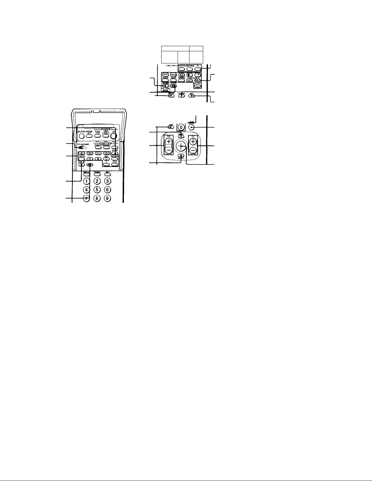
Remote Control
In Ihc iiislnuiuniti Hull h'llinv, :iv u'lll
rcU'r lo Ihr I'lilloii^ on Mony rcinolo coniwl.
Keep llii^ flap unfolded and u>e lliia pope
tor referciiee.
SLEEP
(page 26)
VTR1/2/3/DVD/
MDP (page 52)
VCR/DVD/MDP
operation
buttons (page 53)
CODE SET
(page 52, 54)
MTS (page 27)
MUTING.
(page 25)
SYSTEM OFF
(page 27)
TV/DBS/
PICTURE MODE
(pages 35»54)
GUIDE/ CC (page 26)
DISPLAY (page 26) J
JUMP
(page 25)~[
MENU
(page 34)
VOL +/-
(page 25)
RESET
(page 35)
"T
MUTING SYSIBil
OfF
VTR CA
oc
(b ® ®
@00
@0 @
SONY
'__J
f fv
POWER
(pages 25, 53)
FUNCTION
(pages 25, 52)
PIP/P&P/
CHANNEL
INDEX
(pages 28-
33)
TV/VIDEO
(page 27)
ANT
(page 27)
0-9 buttons
(page 25)
ENTER
(pages 25, 52)
CH +/-
(page 25)
Joystick
(page 22)
Getting to know the buttons on the
remote control
Names of the buttons on the remote control are
presented in different colors to represent the
available functions.
Button color
Black
...............
Press to select the component
you want to control; e.g. VTR
(VCR)/MDP/DVD Player,
DBS (Direct Broadcast
Satellite)/CABLE, or projection
TV.
Green .............. Buttons relevant to power
operations, like turning the
projection TV, DBS/CABLE, or
VTR (VCR)/MDP/DVD Player
on or off.
Label color
Green
White
...............
...............
SYSTEM OFF button
TV/VTR (VCR)/MDP/DVD
Player/DBS (Direct Broadcast
Satellite) / CABLE / S-Link
operation buttons.
Yellow
.............
PIP, P&P, and CHANNEL
INDEX operation buttons.
Blue
.................
Pink
.................
I or a detailed cxfilanatiuii of most buttons, see
"Watching the TV" on page 25.
DBS operation buttons.
DVD Player operation buttons.
Page 4
WARNING
To prevent fire or shock hazard, do not expose the TV to rain or moisture.
CAUTION
RISK OF ELECTRIC SHOCK
DO NOT OPEN
ATTENTION
RISQUE DE CHOC ELECTRIQUE,
NE PAS OUVRIR
PRECAUCION
RIESGO DE CHOQUE ELECTRICO
NO ABRIR
CAUTION : TO REDUCE THE RISK OF ELECTRIC SHOCK,
DO NOT REMOVE COVER (OR BACK).
NO USER-SERVICEABLE PARTS INSIDE
I
REFER SERVICING TO QUALIFIED SERViCE PERSONNEL.
This symbol is intended to alert the user to
the presence of uninsulated "dangerous
voltage" within the product's enclosure that
may be of sufficient magnitude to constitute
A
a risk of electric shock to persons.
This symbol is intended to alert the user to
the presence of important operating and
maintenance (servicing) Instructions in the
A
literature accompanying the appliance.
CAUTION
To prevent electric shock, do not use this polarized
AC plug with an extension cord, receptacle or other
outlet unless the blades can be fully inserted to
prevent blade exposure.
CAUTION
When using TV games, computers, and similar products
with your projection TV, keep the brightness and
contrast functions at low settings. If a fixed (non
moving) pattern is left on the screen for long periods
of time especially at a high brightness or contrast
setting, the image can be permanently imprinted onto
the screen. These types of imprints are not covered by
your warranty because they are the result of misuse.
Note on Caption Vision
This television receiver provides display of television
closed captioning in accordance with §15.119 of the
FCC rules.
Note on convergence adjustment
Before you use your projection TV, make sure to adjust
convergence. For details, see page 24.
Note to CATV system installer
This reminder is provided to call the CATV system
installer's attention to Article 820-40 of the NEC that
provides guidelines for proper grounding and, in
particular, specifies that the cable ground shall be
connected to the grounding system of the building, as
close to the point of cable entry as practical.
Use of this television receiver for other than private
viewing of programs broadcast on UHF or VHF or
transmitted by cable companies for the use of the
general public may require authorization from the
broadcaster/cable company and/or program owner.
NOTIFICATION
This equipment has been tested and found to comply
with the limits for a Class B digital device pursuant to
Part 15 of the FCC Rules. These limits are designed to
provide reasonable protection against harmful
interference in a residential installation. This
equipment generates, uses, and can radiate radio
frequency energy and, if not installed and used in
accordance with the instructions, may cause harmful
interference with radio communications. However,
there is no guarantee that interference will not occur
in a particular installation. If this equipment does
cause harmful interference to radio or television
reception, which can be determined by turning the
equipment off and on, the user is encouraged to try to
correct the interference by one or more of the
following measures:
« Reorient or relocate the receiving antennas.
• Increase the separation between the equipment and
receiver.
• Connect the equipment Into an outlet on a circuit
different from that to which the receiver is
connected.
• Consult the dealer or an experienced radio/TV
technician for help.
You are cautioned that any changes or
modifications not expressly approved in this
manual could void your authority to operate this
equipment.
This document Is for the remote control RM-Y902
MODELS: KP-53XBR200, KP-61XBR200
Please keep this notice with the instruction manual.
As an ENERGY STAR Partner,
Sony Corporation has
determined that this product
meets the ENERGY STAR
guidelines for energy efficiency.
ATTENTION
Pour prévenir les chocs électriques, ne pas utiliser
cette fiche polarisée avec un prolongateur, une prise
de courant ou une autre sortie de courant, sauf si les
lames peuvent être insérées à fond sans en laisser
aucune partie à découvert.
Page 5

Welcome!
Precautions
Thank you for purchasing the Sony Color
Rear Video Projection TV. This manual is for
models, KP-53XBR200 and KP-61XBR200.
Model KP-53XBR200 is used for illustration
purposes.
The features you will enjoy include:
• DRC (Digital Reality Creation), a
technology unique to Sony, allowing you
to obtain a finer, more detailed picture
with four-times higher-density than the
conventional NTSC picture.
• MID (Multi Image Driver), a newly
developed device, allowing you to enjoy
the following features and, at the same
time, to use your projection TV easily.
- Picture & Picture (P&P) with zoom-in
function (Twin View'^h
- Picture-in-Picture (PIP)
- CHANNEL INDEX, allowing you to
view and choose from twelve
programs
- FAVORITE CHANNEL, allowing you to
view and choose from eight of your
favorite channels
• AUTO FOCUS, allowing you to adjust
convergence automatically.
• S-Link^“, allowing you to synchronize
some operations of your projection TV
with those of other Sony components.
• One Y / Pb / Pk input for DVD Player
connection.
• Five AUDIO / VIDEO / S VIDEO inputs.
Safety
• Operate the projection TV only on 120 V
AC.
• The plug is designed, for safety purposes,
to fit into the wall outlet only one way. If
you are unable to insert the plug fully into
the outlet, contact your dealer.
• I£,,any liquid or solid object should fall
inside the cabinet, unplug the projection TV
immediately and have it checked by
qualified service personnel before operating
it further.
• If you will nof be using the projection TV
for several days, disconnect the power by
pulling the plug itself. Never pull on the
cord.
For details concerning safety precautions, see the
supplied leaflet "IMPORTANT SAFEGUARDS."
Note on cleaning
Clean the cabinet of the projection TV with a
dry soft cloth. To remove dust from the
screen, wipe it gently with a soft cloth.
Stubborn stains may be removed with a cloth
slightly dampened with solution of mild soap
and warm water. Never use strong solvents
such as thinner or benzine for cleaning.
If the picture becomes dark after using the
projection TV for a long period of time, it may
be necessary to clean the inside of the
projection TV. Consult qualified service
personnel.
Installing
• To prevent internal heat buildup, do not
block the ventilation openings.
• Do not install the projection TV in a hot or
humid place, or in a place subject to
excessive dust or mechanical vibration.
• If fhe projection TV is transported directly
from a cold to a warm location, or if the
room temperature has changed suddenly,
the picture may be blurred or show poor
color. In this case, let the moisture
evaporate before using the projection TV.
• To obtain the best picture, do not expose
the screen to direct illumination or direct
sunlight. It is recommended to use spot
lighting directed down from the ceiling or
to cover the windows that face the screen
with opaque drapery. It is desirable to
install the projection TV in a room where
the floor and walls are not of reflecting
material.
Page 6
í';-:
insTdHing and Connecting die Projection T
Tliis manual is divided into four major
sections. We recommend that you carefully
review the contents of each section in the
order provided to ensure that you fully
understand the operation of your new
projection TV.
1 Installing and Connecting the
Projection TV.
Carrying your projection TV
Carrying the projection TV requires three or
more people.
The projection TV has been equipped with
casters for easy movement. Please move your
projection TV using the casters.
This section will guide you through your
initial set up. It will show you how to
connect your new components and how
to connect to your antenna or cable.
2 Basic Set Up.
This section will teach you the basic skills
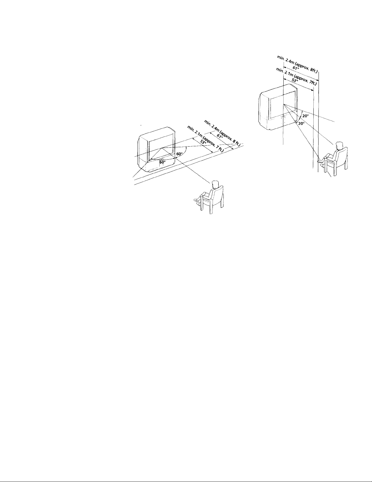
Installing the Projection TV
Recommended viewing area (Horizontal)
needed to operate your new projection
TV. It will show you how to operate
special functions of the remote control.
3 Using Your New Projection TV.
This section will show you how to begin
using your new projection TV. It will
show you how to use the AUTO SET UP
feature, and how to use your remote
control's features.
4 Adjusting Your Set Up (menus).
This section will teach you how to access
on-screen menus and adjust your
projection TV’s settings.
Instructions in this manual are written for the remote
control. Similar controls may be found on the projection
TV avisóle.
Recommended viewing area (Vertical)
Page 7
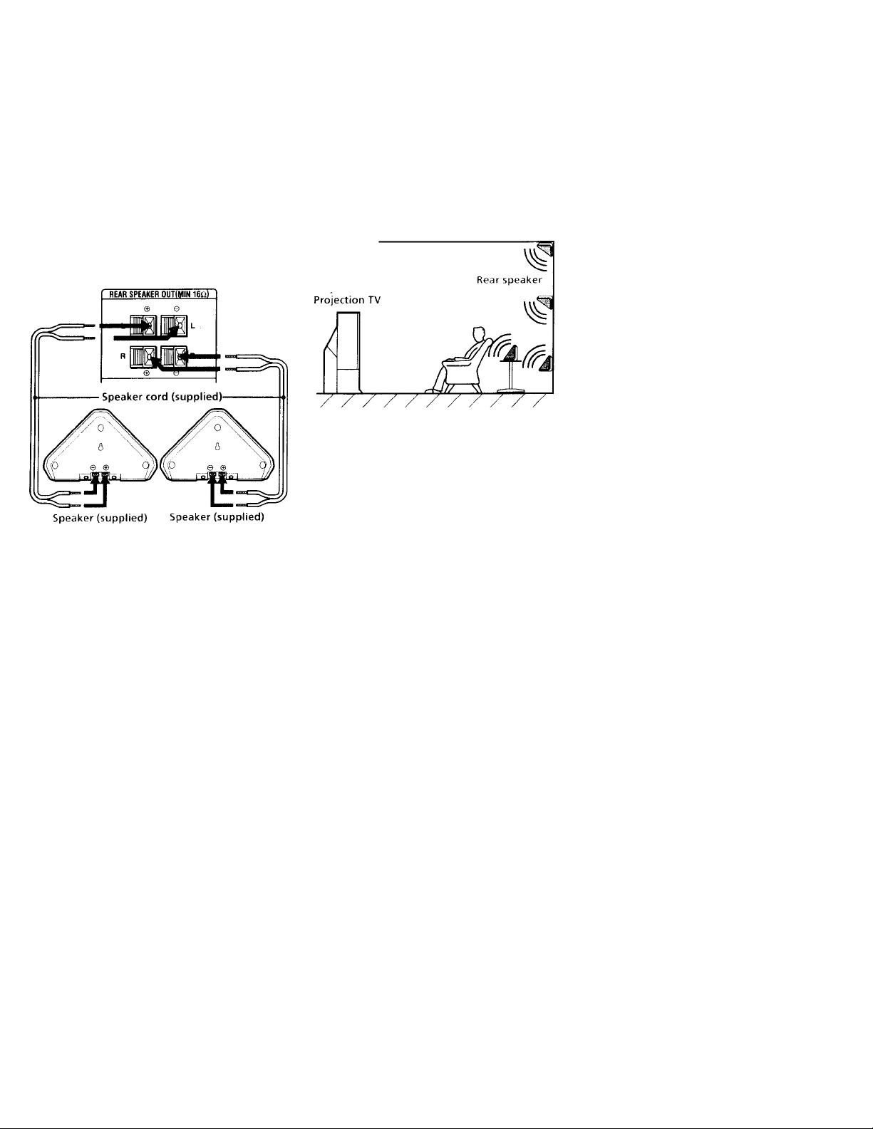
Mounting the Supplied Rear Speakers
For enhanced surround effect, connect the
supplied rear speakers to your projection TV.
Connecting the rear speakers
Using the supplied speaker cord, connect
REAR SPEAKER OUT L on your projection
TV to the speaker terminal on one rear
speaker, and connect REAR SPEAKER OUT R
to the terminal on the other one.
(Rear of projection TV)
installation
For optimum surround effect, mount the rear
speakers in the following places (as shown in
the illustration):
• on a wall, a little higher or lower than the
listener's ears.
• on a table, a little lower than the listener's
e9rs.
• on a corner of wall and ceiling.
(Re I of projectio
Left rear
speaker
^ Right rear
^ speaker
Note:
• Match the colors of the speaker cords and
the terminals. If the colors are reversed,
sound will be distorted.
Page 8

Installing and Connecting the Projection TV (continued)
Connector Types
You mny tind it necessary to use some of the
following connector types during set up.
Coaxial cable
Standard TV cable and antenna connector
Plug Type
Press into connection
Screw-on Type
Z^ZZZlI^-
S Video cable
High quality video connector for enhanced
picture quality
AudioA/ideo cable
Video - Yellow
Audio (Left) - White
Audio (Right) - Red
(Some DVD Players are equipped with the
following three video connectors.)
Y - Green
Pb (Cb, Cb, or B-Y) - Blue
Pr (Ck, Cr, or R-Y) - Red
GH Screw into connection
^ Align guides and
press into connection
"*■ Press into connection
S-Link/CONTROL S cable
Sony connector for S-Link and CONTROL S
connections. These features are exclusive to
Sony products and allow greater control of
all Sony equipment.
Q Press into connection
Note:
• For S-Link and CONTROL S connections,
you can use the combined S-Link/
CONTROL S cable provided with some
Sony video equipment, or you can
purchase a separate S-Link / CONTROL S
cable (RK-G69HG).
Making Connections
For the best picture quality, a cable TV
system or outdoor antenna is recommended.
Connecting directly to cable or an antenna
The connection you choose will depend on
the cable found in your home. Newer homes
will be equipped with standard coaxial cable
(see A); older homes will probably have 300ohm twin lead cable (see B); still other
homes may contain both (see C).
A
■ VHF only
or
■ VHF/UHF
or
■ Cable
' VHF only
or
' UHF only
or
VHF/UHF
VHF
and
UHF
300-ohm twin lead cable
75-ohm
coaxial cable
300-ohm twin
lead cable
Antenna connector
75-ohm coaxial cable
iW)
(Rear of
projection TV)
VHF/UHF
(Rear of
projection TV)
VHF/UHF
(Rear of
projection TV)
VHF/UHF
EAC-66 U/V mixer
(not supplied)
Page 9

I
Cable or antenna
Most simple connection. Connection is made
directly from the cable or antenna to the
projection TV.
(Rear of projectiorrTV)
Cable
VHF/UHF
Cable and antenna
You may find it convenient to use the
following set up if your cable provider does
not feature local channels that you are able to
receive using an antenna.
(Rear of projection TV)
CATV cable
Antenna cable
AUX
VHF/UHF
Ijl
Select Cable or ANT mode by pressing ANT
on the remote control.
Connecting a cable box
Some pay cable TV systems use scrambled ctr
encoded signals that require a cable box* to
view all channels.
(Rear of projection TV)
Cable
IN OUT
*Cable box
VHF/UHF
Note:
• If you will be controlling all channel
selection through your cable box, you
should consider using the CHANNEL EIX
feature, (see "CHANNEL FIX" on page
45)
Cable box and cable
Some pay cable TV systems use scrambled or
encoded signals requiring a cable box* only for
certain channels (e.g. HBO, SHOWTIME, etc.).
‘Cable box
CATV cable
(unscrambled channels)
(Rear of projection TV)
AUX
VHF/UHF
For this set up, you can switch between
scrambled channels (through your cable box), and
normal (CATV) channels by pressing ANT on
your remote control.
Notes:
• You may be able to program your Sony
remote control to operate your cable box.
(see "Operating a Cable Box or DBS
Receiver" on page 54)
• During PIP, P&P,(ZHANNEL INDEX or
FAVORITE CHANNEL viewing, the AUX
input can only be viewed in the main picture.
• If you are connecting a cable box through the
AUX input and would like to switch between
the AUX and normal (CATV) input you
should consider using CHANNEL FIX.
(see "CHANNEL FIX" on page 45)
Page 10
>a and Connecting the Projection TV (continued)
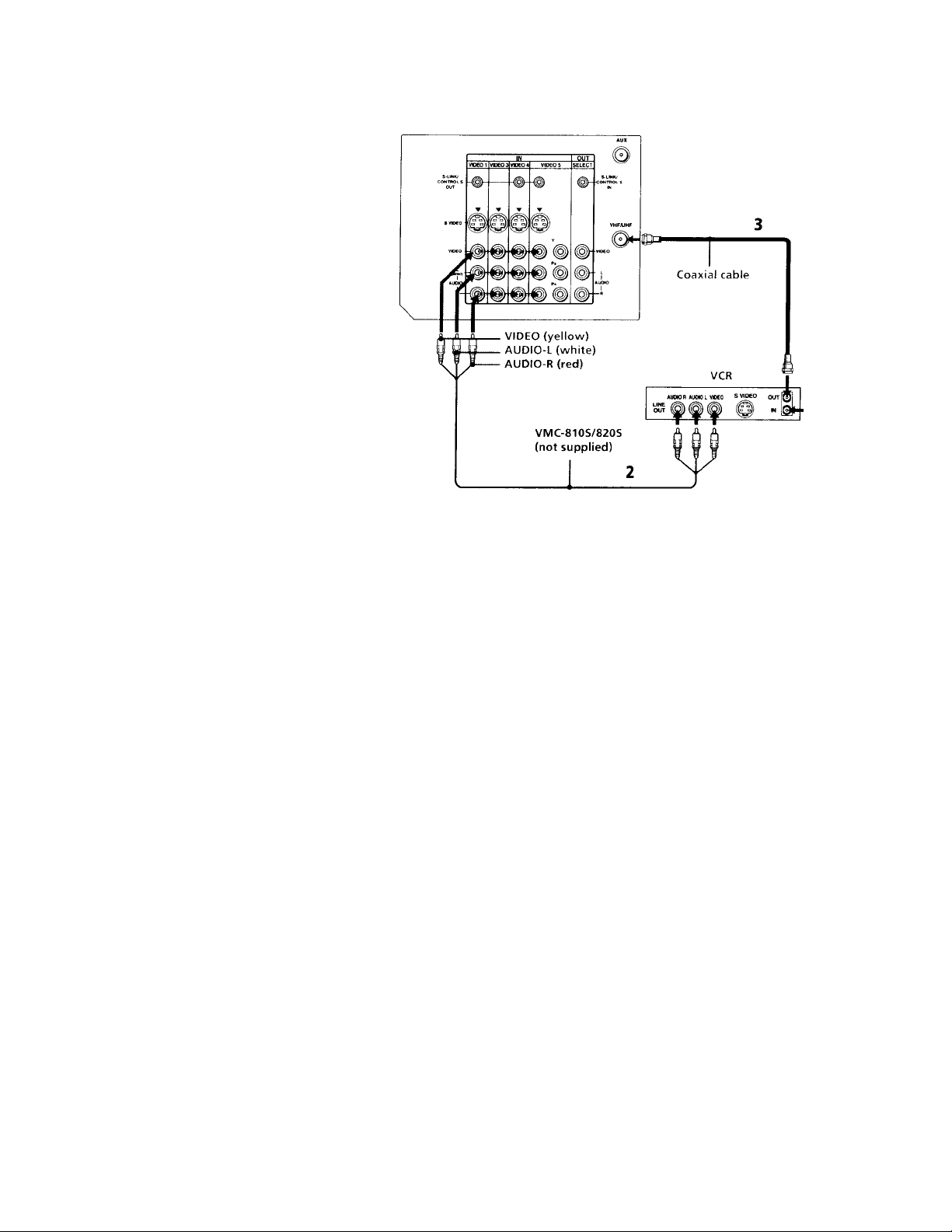
Connecting an antenna/cable TV
system with a VCR
1 Attach the coaxial connector from your
cable or antenna to IN on your VCR.
2 Using AUDIO/VIDEO connectors,
connect AUDIO and VIDEO OUT on your
VCR to AUDIO and VIDEO IN on your
projection TV (Yellow-VIDEO, WhiteAUDIO Left, Red-AUDIO Right).
3 Using a coaxial connector, connect OUT
on your VCR to VHF/UHF on your
projection TV.
Note:
• If you are connecting a monaural VCR,
connect only the single audio output to
the left (MONO) input on your projection
TV.
Disconnect all power sources before making any connections.
(Rear of projection TV)
Cable
Page 11
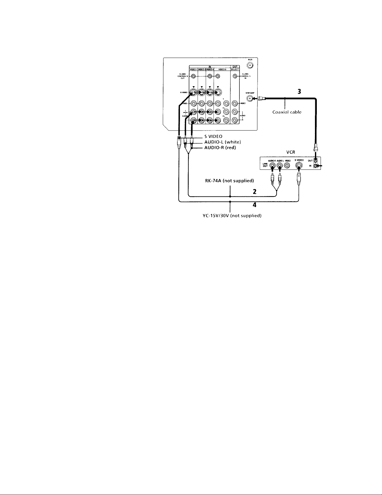
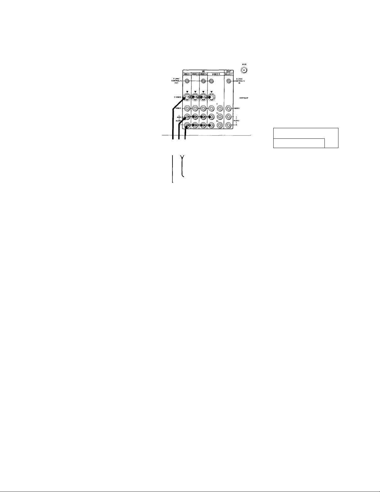
Connecting to an S Video equipped
VCR
1 Attach the coaxial connector from your
cable or antenna to IN on your VCR.
2 Using AUDIO connectors, connect AUDIO
OUT on your VCR to AUDIO IN on your
projection TV (White-AUDIO Left, RedAUDIO Right).
3 Using a coaxial connector, connect OUT
on your VCR to VHF/UHF on your
projection TV.
4 Using an S VIDEO connector, connect
S VIDEO on your VCR to S VIDEO on
your projection TV.
Note:
• If you are connecting a monaural VCR,
connect only the single audio output to
the left (MONO) input on your projection
TV.
Disconnect all power sources before making any connections.
(Rear of projection TV)
Cable
SPD——
Page 12
Installing and Connecting the Proie’:
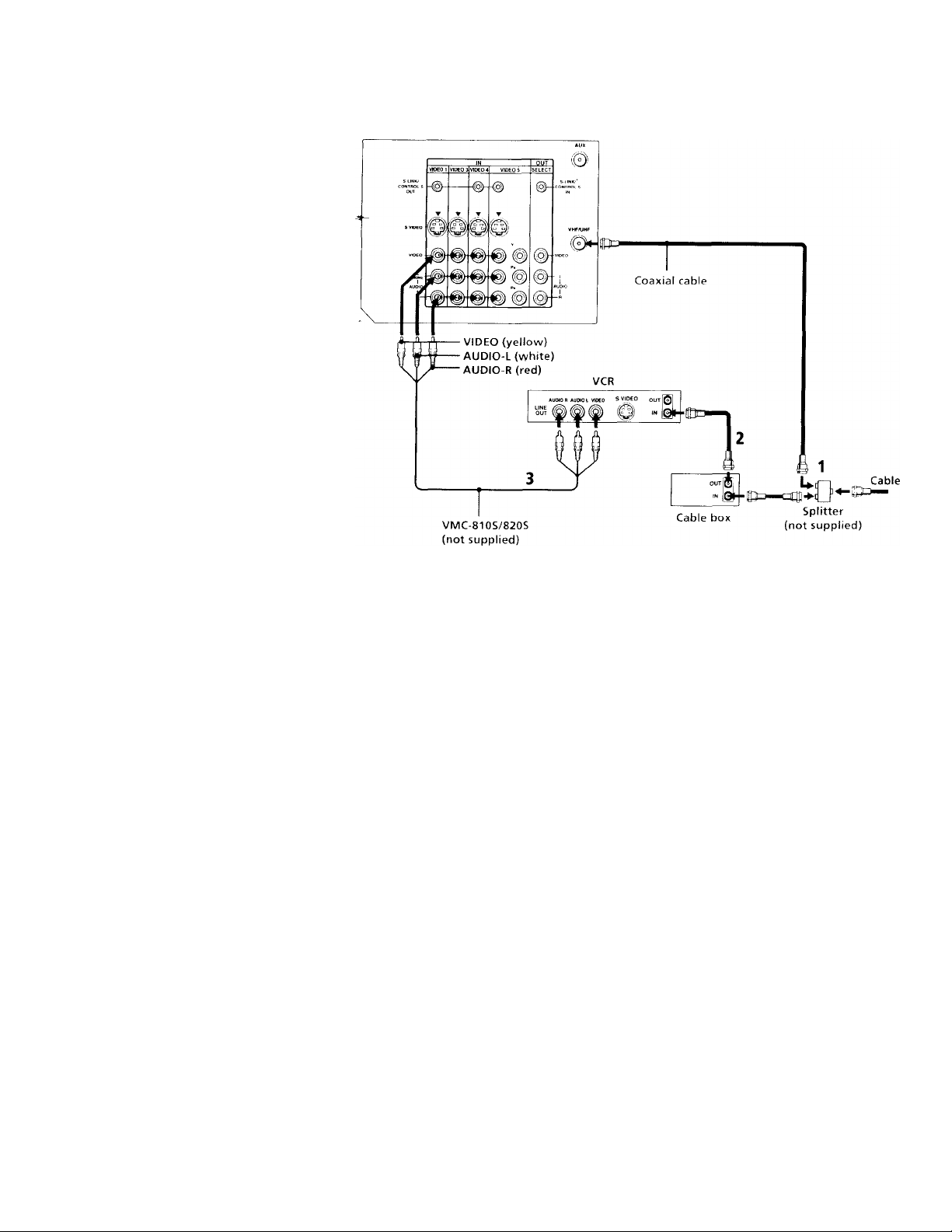
Connecting a VCR and projection
TV with a cable box
1 Connect the single (input) jack ot the
Splitter to your incoming cable
connection, and connect the other two
(output) jacks (using coaxial cable) to IN
on your cable box and VHF/UHF on your
projection TV.
2 Using a coaxial connector, connect OUT
on your cable box to IN on your VCR.
3 Using AUDIO/VIDEO connectors,
connect AUDIO and VIDEO OUT on your
VCR to AUDIO and VIDEO IN on your
projection TV (Yellow-VIDEO, WhiteAUDIO Left, Red-AUDIO Right).
Note:
• To view scrambled channels through your
cable box, select the video input which
your cable box is connected to by pressing
TV/VIDEO.
tion TV (continued)
Disconnect all power sources before making any connections.
(Rear of projection TV)
Page 13
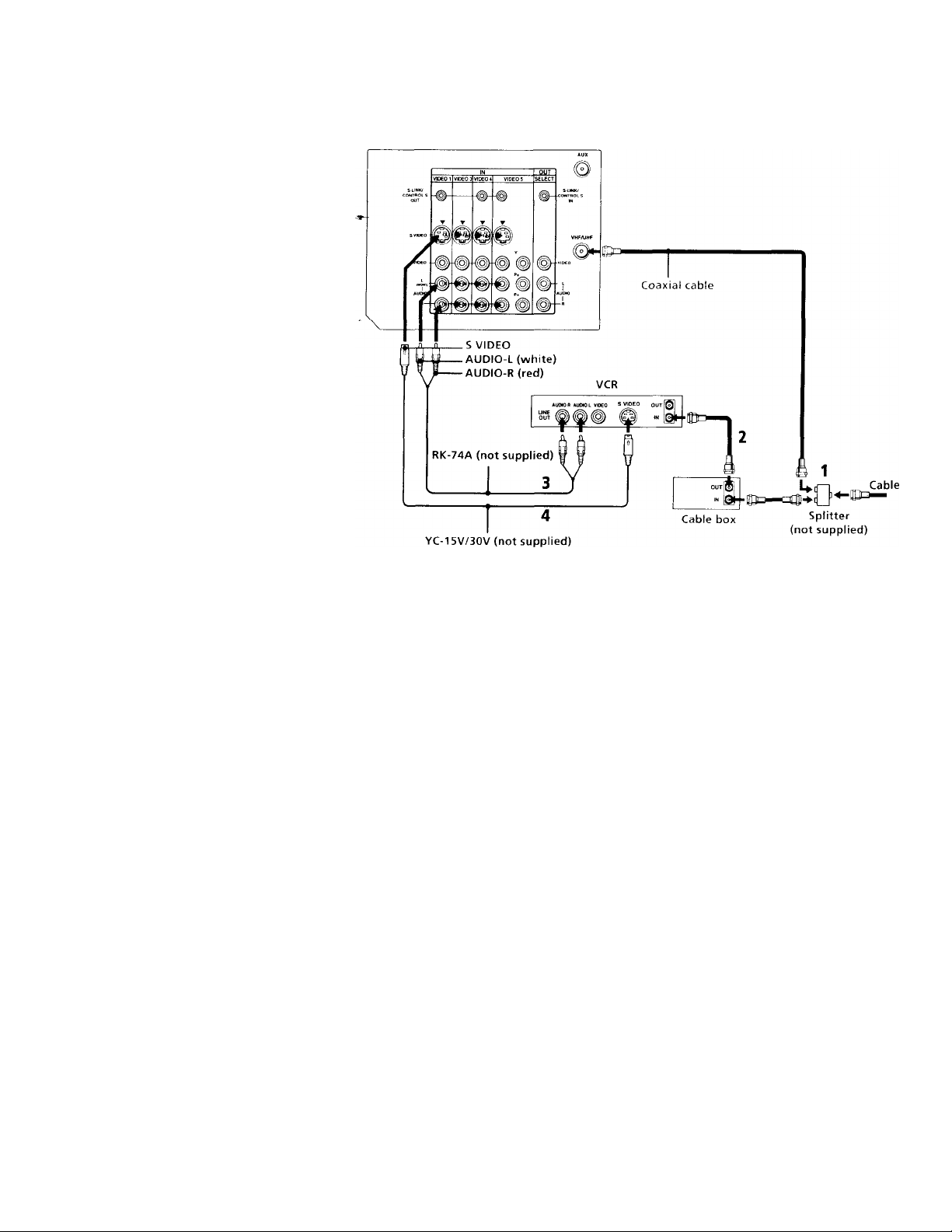
Connecting to an S Video equipped
VCR with a cable box
1 -2 Perform as described on page 8.
3 Using AUDIO connectors, connect
AUDIO OUT on your VCR to AUDIO IN
on your projection TV (White-AUDIO Left,
Red-AUDIO Right).
4 Using an S VIDEO connector, connect S
VIDEO on your VCR to S VIDEO on your
projection TV.
Note:
• To view scrambled channels through your
cable box, select the video input which
your cable box is connected to by pressing
TV/VIDEO.
Disconnect all power sources before making any connections.
(Rear of projection TV)
Page 14
Installing and Connecting the Projection TV (continued)
Connecting a DBS (Direct Broadcast Satellite) receiver
1 Connect the cable from your satellite
antenna to your DBS receiver.
(Rear of projection TV)
2 Attach the coaxial connector from your
cable or antenna to VHF/UHF on your
projection TV.
3 Using AUDIO connectors, connect
AUDIO OUT on your DBS receiver to
AUDIO IN on your projection TV (White-
AUDIO Left, Red-AUDIO Right).
4 Using an S VIDEO connector, connect S
VIDEO on your DBS receiver to S VIDEO
on your projection TV.
• To view input from the DBS, select the
U
W“W
----
AUDIO-L (white)
video input which your DBS receiver is V \ P--------AUDIO-R (red)
connected to by pressing TV / VIDEO on
the remote control. RK-74A (not supplied)
____
YC-15V/30V (not supplied)
Disconnect all power sources before making any connections.
Satellite antenna
cable
Cable
DBS
SAT6(LtEIN
1^' *UM0 R *UDtO L VIOCO S VIDEO Î0l IN
VHF/UHF
¡©jouT
L
10
Page 15
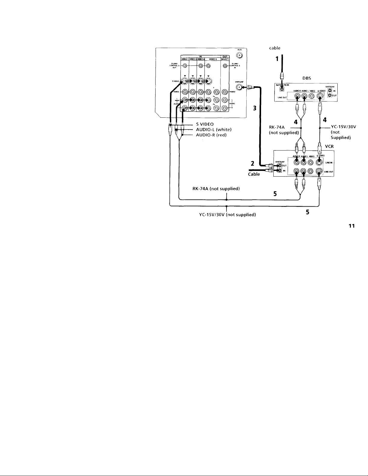
Connecting a DBS (Direct
Broadcast Satellite) receiver and a
VCR
1 Connect the cable from your satellite
antenna to your DBS receiver.
2 Attach the coaxial connector from your
cable or antemaa to VHP / UHF IN on your
VCR.
3 Using a coaxial connector, connect VHP /
UHP OUT on your VCR to VHP/UHF on
your projection TV.
4 Using AUDIO and S VIDEO connectors,
connect AUDIO OUT and S VIDEO on
your DBS receiver to AUDIO IN and S
VIDEO on your VCR.
5 Using AUDIO and S VIDEO connectors,
connect AUDIO OUT and S VIDEO on
your VCR to AUDIO IN and S VIDEO on
your projection TV (White-AUDIO Left,
Red-AUDIO Right).
Notes:
• To view input from the DBS or VCR,
select the video input which your DBS
receiver or VCR is connected to by
pressing TV / VIDEO on the remote
control.
• If your VCR is not equipped with S
VIDEO, connect VIDEO OUT on your
VCR to VIDEO IN on your projection TV
using AUDIO/VIDEO connectors.
Disconnect all power sources before making any connections.
(Rear of projection TV)
Satellite antenna
Page 16
'll.’
Installing and Connecting the Projection TV (continued)
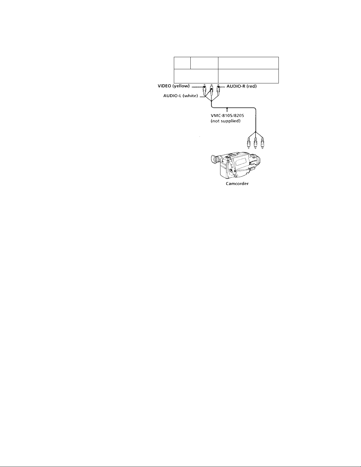
Connecting a camcorder
Use this connection to view a picture directly
from vour camcorder.
Using AUDIO/VIDEO connectors, connect
AUDIO and VIDEO OUT on your camcorder
to AUDIO and VIDEO IN on the front panel
of your projection TV (Yellow-VIDEO, WhiteAUDIO Left, Red-AUDIO Right).
Notes:
• If you are connecting a monaural
camcorder, connect only the single audio
output to the left (MONO) input on your
projection TV.
• If you have an S Video equipped
camcorder, you can use an S Video
connection.
s vioeo
V VIDEO i.(«IO»OF»uD
©
L 11
Disconnect all power sources before making any connections.
(Front of projection TV)
1 O O :
VlOB 2 iVUT
/ ______________________I_____________________
A
Audio/video
outputs
12
Page 17
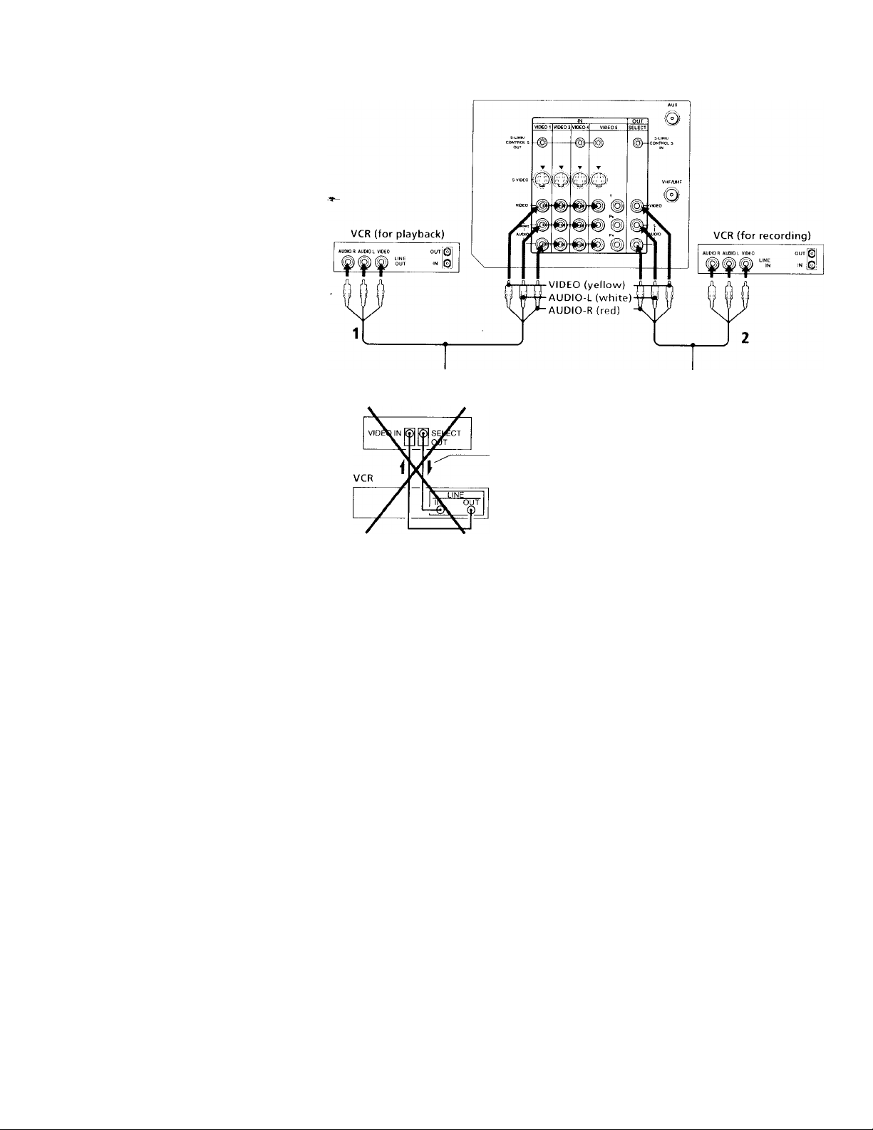
Connecting two VCRs for tape editing
SELECT OUT gives you the ability to use a
second VCR to record a program being
played by the primary VCR or to perform
tape editing and dubbing.
1 Connect the VCR intended for playback
using the connection instructions on
pages 6 and 7 of this manual,
2 Using AUDIO/VIDEO connectors,
connect AUDIO and VIDEO IN on your
VCR intended for recording to SELECT
OUT AUDIO and VIDEO on your
projection TV.
Notes:
• Do not change the input signal while
editing through SELECT OUT.
• When connecting a single VCR to the
projection TV: if VCR LINE OUT is
connected to projection TV's VIDEO IN,
do not connect the projection TV's
SELECT OUT jacks to the VCR LINE
INPUT (see right). Doing so will cause
program interference and other viewing
problems.
• You can select the output signal from
SELECT OUT from the SET UP menu, (see
"SELECT OUT" on page 48)
VMC-810S/820S (not supplied)
(Rear of projectionTV)
Disconnect all power sources before making any connections.
(Rear of piojettion TV)
VMC-810S/820S (not supplied)
Indicates direction
of signal
13
Page 18
Installing and Connecting the Projection TV (continued)
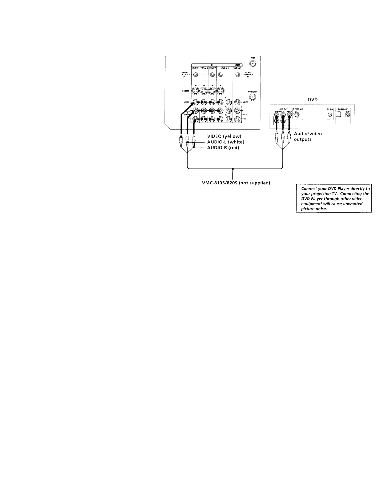
Connecting a DVD Player without component video output
connectors (Rear of projection TV)
Using AUDIO/VIDEO connectors, connect
AUDIO and VIDEO IN on your projecfion TV
to LINE OUT on your DVD Player.
Note:
• Since the high quality pictures on a DVD
disc contain a lot of information, picture
noise may appear. In this case, adjust NR
in the ADVANCED VIDEO menu, (see
"NR" on page 37)
Disconnect all power sources before making any connections.
14
Page 19
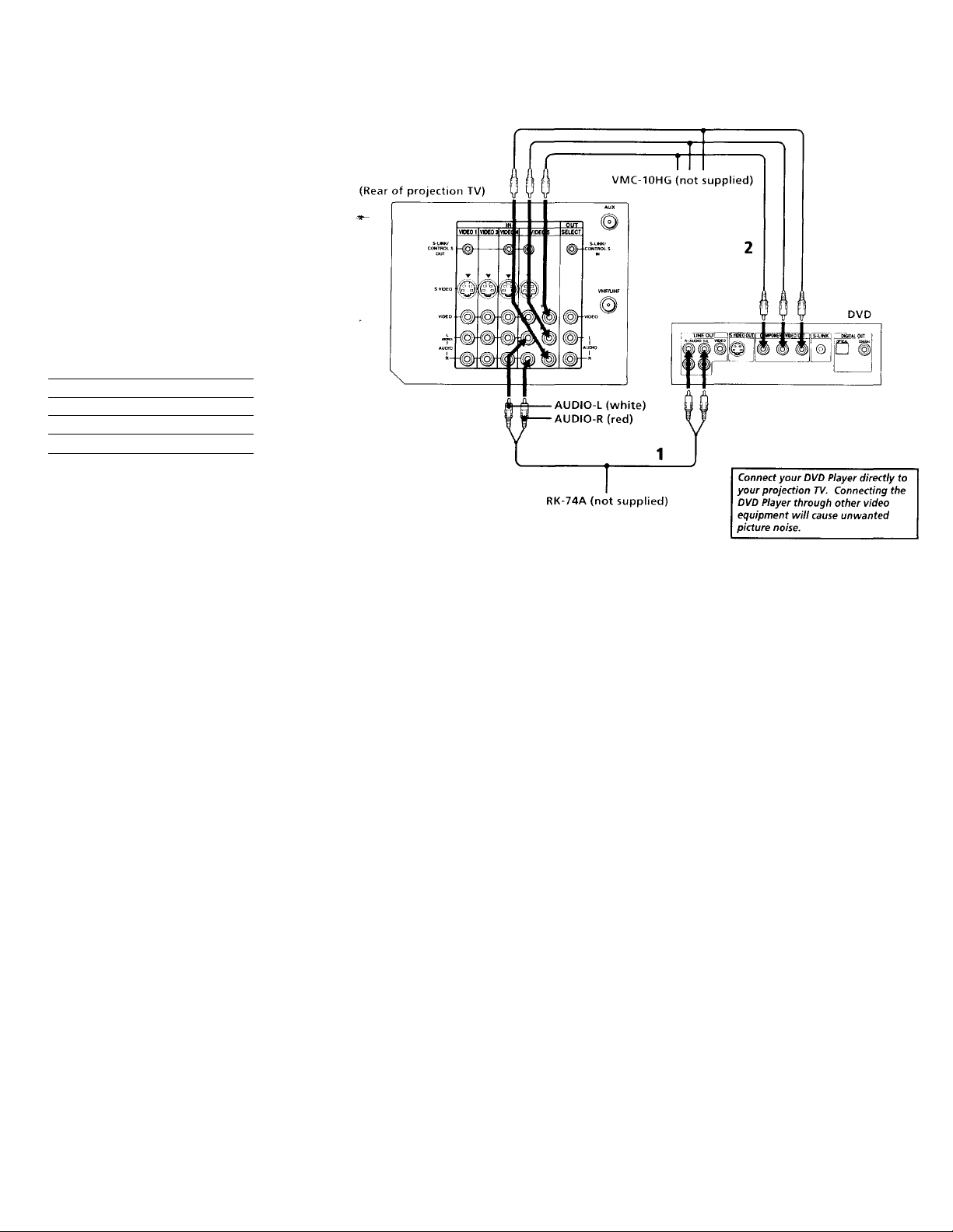
Connecting a DVD Player with component video output connectors
1 Using AUDIO connectors, connect AUDIO
R and L of the LINE OUT on your DVD
Player to AUDIO R and L on the VIDEO 5
IN panel at the rear of your projection TV.
2 Using three yellow VIDEO connectors,
connect Y, Pb, and Pr on the
COMPONENT VIDEO OUT on your DVD
Player to Y, Pb, and Pk on the VIDEO 5 IN
panel at the rear of your projection TV.
Notes;
• Some DVD Player terminals may be
labeled differently. If so, connect as
follows:
Connect To
Y (green) Y
Pb (blue)
Pr (red)
Cb, Cb, or B-Y
Cr, Cr, or R-Y
Since the high quality pictures on a DVD
disc contain a lot of information, picture
noise may appear. In this case, adjust NR
in the ADVANCED VIDEO menu, (see
"NR" on page 37)
Disconnect all power sources before making any connections.
15
Page 20
Installing and Connecting the Projection TV (continued)
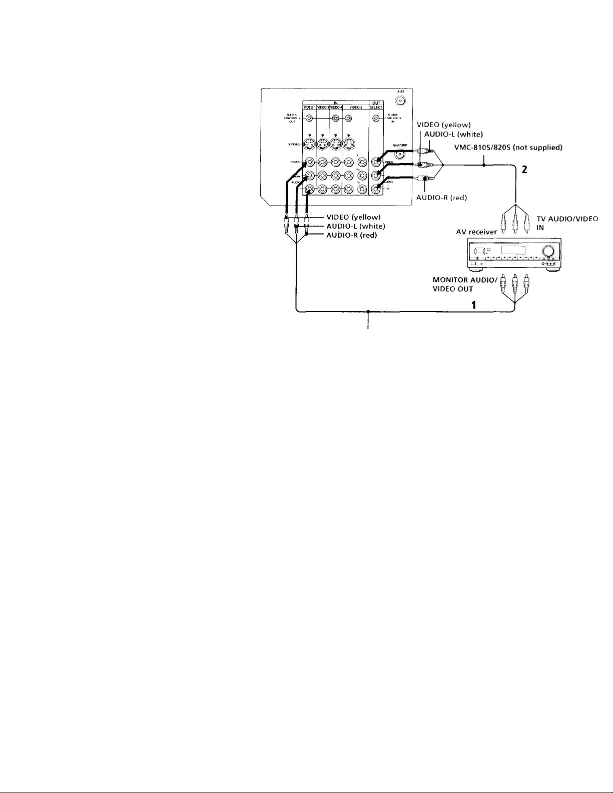
Connecting an AV receiver
For greater control of all audio and video
equipment, connect your AV receiver.
1 Using AUDIO/VIDEO connectors, connect
VIDEO 1 IN on your projection TV to
Monitor AUDIO and VIDEO OUT on your
AV receiver.
2 Using AUDIO/VIDEO connectors, connect
SELECT OUT on your projection TV to TV
AUDIO and VIDEO IN on your AV
receiver.
3 Use the SET UP menu to set SELECT OUT
to TV OUT. (see "SELECT OUT" on page
48)
Disconnect all power sources before making any connections.
(Rear of projection TV)
16
VIVIC-810S/820S (not supplied)
Page 21
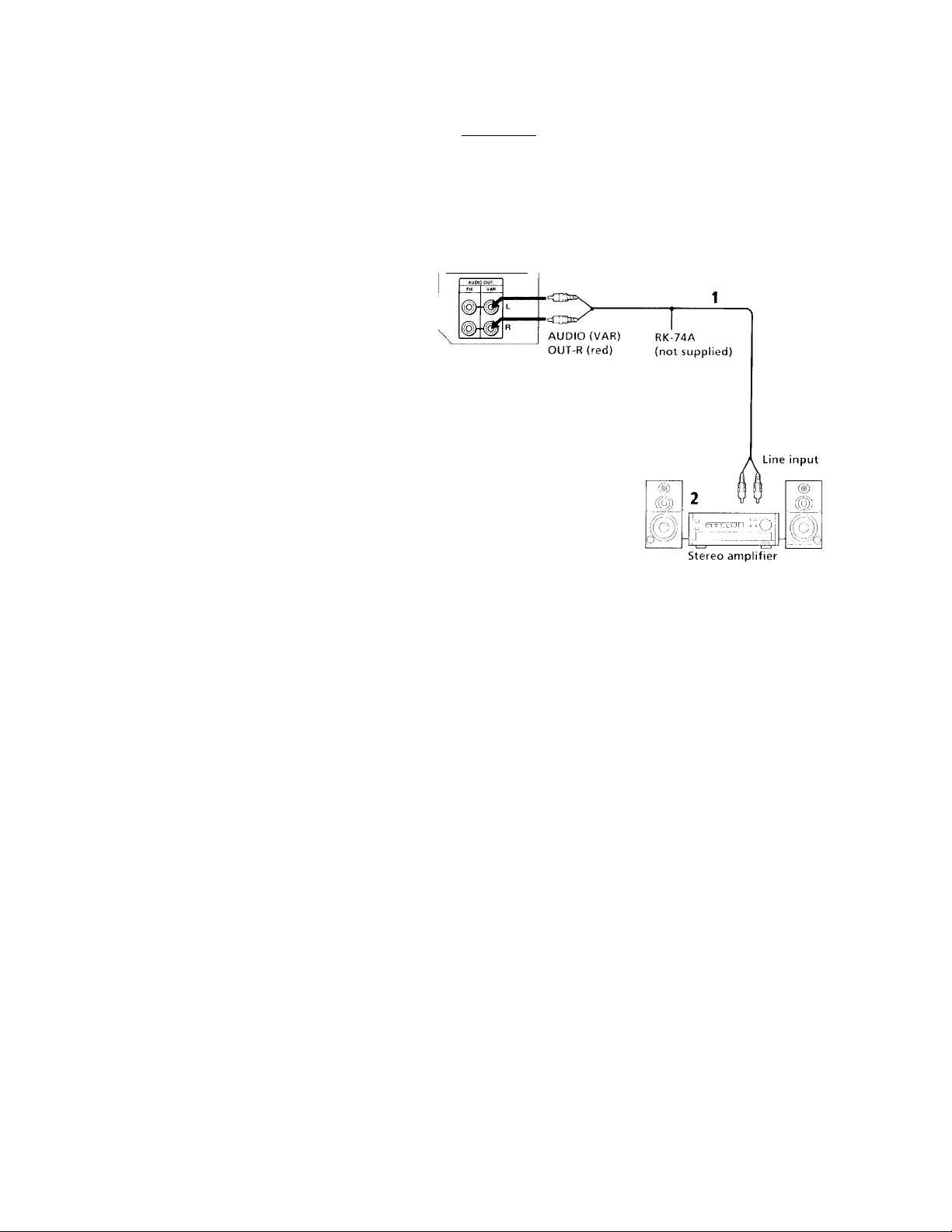
Connecting an audio system
For more dynamic sound, connect your audio
system to your projection TV.
1 Using AUDIO connectors, connect AUDIO
(VAR) OUT on your projection TV to one of
the unused Line inputs (e.g. Tape-2, AUXl,
etc.) on your stereo (White-AUDIO Left, Red-
AUDIO Right).
2 Set your stereo to the chosen Line input
and use the AUDIO menu to switch
projection TV's speakers off. (see
"SPEAKER" on page 38)
Note:
• You can adjust VOLUME, BASS, TREBLE
and BALANCE through the projection TV
on AUDIO (VAR) OUT only.
Disconnect all power sources before making any connections.
(Rear of projection TV)
■B SPEAKER OUT(MIN16
AUDIO (VAR) OUT L
(white)
17
Page 22

Instailino and
Ccnnectmg the Projection TV (continued)
Connecting an amplifier with Dolby Pro Logic decoder
If you use an amplifier with Dolby Pro Logic
decoder instead of the projection TV's audio
system, you can still use the projection TV's
center speaker.
1 Using the speaker cords (supplied with
the amplifier), connecf the speaker
terminals on your amplifier to CENTER
SPEAKER IN +/ - on your projection TV.
2 Using AUDIO/VIDEO connectors,
connect AUDIO (FIX) OUT on your
pirojection TV to one of the unused Line
inputs (e.g. Tape-2, AUXl, etc.) on your
amplifier (White-AUDIO Leff, redAUDIO Right).
3 Set your amplifier to the chosen Line
input and use the AUDIO menu to set
"SPEAKER" to "CENTER IN" on your
projection TV. (see "SPEAKER" on page
38)
18
AUDIO
(FIX) OUT-L
(white)
* Manufactured under license from
Dolby Laboratories Licensing
Corporation. Additionally licensed
under Canadian patent number
1,037,877. "Dolby," the double-D
symbol □□ and "Pro Logic" are
trademarks of Dolby Laboratories
Licensing Corporation.
Disconnect all power sources before making any connections.
{Rear of projection TV)
RK-74A (not supplied)
Line input
Amplifier with Dolby*
Pro Logic decoder
Rear
speaker (L)
Front
speaker (L)
Front
speaker(R)
Rear
speaker(R)
Page 23

Using the S-Link/CONTROL S
function
S-Link is a Sony innovation designed to
make your Sony components work together.
It allows you to automatically switch the
projection TV's input mode to video when
you press the play button on your Sony SLink VCR. It also allows you to turn the VCR
and projection TV off at the same time with
the SYSTEM OFF button on the remote
control.
Using the S-Link function without
a Sony AV receiver
1 Connect your VCR. (see "Connecting an
antenna / cable TV system with a VCR" or
"Connecting to an S Video equipped
VCR" on pages 6 and 7)
2 Using an S-LINK cormector, connect the
S-LINK jacks on your VCR (DVD) and
projection TV. Ensure that both ends are
seated firmly and that the projection TV's
S-LINK jack is in the same row as the
AUDIO/VIDEO connectors.
S-LINK
(black)
Disconnect all power sources before making any connections.
S-LINK
19
Page 24

Installing and Connecting the Projection TV (continued)
Using the S-Link function with a Sony AV receiver
1 Using VIDEO connector, connect VIDEO
1 IN on your projection TV to MONITOR
VIDEO OUT on your Sony AV receiver.
2 Using AUDIO/VIDEO connectors,
connect SELECT OUT on your projection
TV to TV AUDIO and VIDEO IN on your
receiver.
3 Using an S-LINK connector, connect S-
LINK on VIDEO 1 IN on your projection
TV and S-LINK on MONITOR OUT on
your AV receiver.
4 Using an S-LINK connector, connect
projection TV's S-LINK on SELECT OUT
to S-LINK on TV IN on your AV receiver.
5 Using AUDIO/VIDEO and S-LINK
connectors, connect your Sony video
equipment to your AV receiver.
6 Use the AUDIO menu to set SPEAKER to
ALL OFF or CENTER IN. (see
"SPEAKER" on page 38)
7 Use the SET UP menu to set SELECT
OUT to TV OUT. (see "SELECT OUT" on
page 48)
Disconnect all power sources before making any connections.
20
Page 25

Using the CONTROL S feature
CONTROL S allows you to control your
projection TV and other Sony equipment with
one remote control.
To control other Sony equipment with your
projection TV's remote control, connect the
CONTROL S IN jack of the equipment to the
CONTROL S OUT jack on the projection TV
with the CONTROL S cable.
To control your projection TV with other
Sony equipment's remote control, connect the
CONTROL S OUT jack of the equipment to
the CONTROL S IN jack on the projection TV
with the CONTROL S cable.
Disconnect all power sources before making any connections.
(Rear of projection TV)
21
Page 26

Basic Set Up
Inserting Batteries
Insert two size A A (R6) batteries (supplied)
by matching the + and - on the batteries to
the diagram inside the remote control's
battery compartment.
Notes:
• Remove the batteries to avoid damage
from possible battery leakage whenever
you anticipate that the remote control will
not be used for an extended period.
• Handle the remote control with care.
Avoid dropping it, getting it wet, or
placing it in direct sunlight, near a heater
or where the humidity is high.
• Your remote control can be programmed to
operate most video equipment.
(see "Operating Video Equipment" on
page 52)
Using the Remote Control Joystick
© © ©
® © ©
© ® ®
o © O
Select
The supplied remote control has a joystick
which moves the on-screen selector in eight
directions. In most cases, moving the joystick
up, down, left or right will cause the selector
to move in the selected direction.
In some cases, the selector may move in eight
directions according to your moving
direction. Pressing down on the center of the
joystick ( 0 ) will activate the selected item.
You may also move the joystick right to
activate the selected item. (There are some
exceptions to this option.)
Adjusting Sliders
when menu items present a slider ( ■§— or
-), move the joystick up, down, left or right
to adjust the setting.
IP spttinv
Additional Menu Instructions
Several menu windows will provide prompts
and instructions to assist you in navigating
through the different functions.
When the instructions are presented, use them to
supplement the instructions in this manual.
22
Page 27

Using Your New Projection TV
Setting Up the Projection TV Automatically
The AUTO SET UP feature will allow you to
set the on-screen language and set all
receivable channels.
The AUTO SET UP feature does not apply for
installations that use a cable box for all channel
selection.
You can also set up the projection TV manually,
(see "Using the CHANNEL SET UP menu" on
page 43)
Notes:
• Before you perform AUTO SET UP again,
make sure that the input from ANT (not
AUX) is selected by pressing ANT until
"AUX" does not appear next to the
channel number.
• Perform this function during the day, with
the antenna and / or cable properly
connected, to ensure that all available
channels will be broadcasting and
receivable.
• When you perform AUTO PROGRAM,
your CHANNEL FIX, ON/OFF TIMER,
and CHANNEL BLOCK settings will be
erased.
• When you perform AUTO SET UP, all the
settings in the VIDEO, ADVANCED
VIDEO and AUDIO menus are reset to the
factory settings.
Using the buttons on the front panel of the
projection TV:
TV,VIDEO - VOLUME * - CHANNEL
0 DÛQ0 0
STEHEOn nTlMER«TAfJD0i
1 #ress POWER to turn on the projection
TV.
The AUTO SET UP screen appears.
DEMO [
(CH*)
1CH-Ì
(VOL * 1
TV / VIDEO ]
1 to exit
ENGLISH
ESPAÑOL
FRANÇAIS
AUTO SET UP [VOL - 1
First please connect
the antenna
Press Í SET UP
2 Press CHANNEL + to select English,
CHANNEL - to select Spanish or
VOLUME + to select French.
The screen will change to reflect your
choice.
- VOLUME + - CHANNEL +
ENGLISH
ESPAÑOL
FRANQAIS (VOL + 1
AUTO SET UP
DEMO [TV/VIDEO i
Primero conecte la
antena
Oprima 1 SET UP para
salir
[CH*1
[CH-]
[VOL-1
For a DEMO of functions and menus, press
TV/VIDEO.
3 Press VOLUME - to continue.
YES (CH.)
NO ICH- ]
Ò
4 Press CHANNEL -t to preset channels
automatically.
"AUTO PROGRAM" appears and the
projection TV starts scanning and
presetting channels automatically. While
scanning, the received channel will be
displayed on the sub screen. When all the
receivable channels are stored, the lowest
numbered channel is displayed. If the
projection TV receives cable TV channels,
CABLE is set to ON automatically.
(continued)
23
Page 28

Using Your New Projection TV (continued)
To perform AUTO SET UP again
• Press SET UP inside the drop-down panel
on the projection TV.
• Press CHANNEL -r, CHANNEL - or
VOLUME -I- to select a language.
• Press VOLUME - to restore factory
settings ("CONTINUE TO AUTO
PROGRAM?" will appear on the screen.
Press CHANNEL+ to execute or
CHANNEL- to exit).
• Press SET UP to exit.
24
Adjusting the Convergence Automatically (AUTO FOCUS)
The projection tube image appears on the
screen in three layers (red, green and blue). If
they do not converge, the color is poor and
the picture blurs.
Before you use your projection TV, be sure to
adjust the convergence. The AUTO FOCUS
feature allows you to adjust the convergence
automatically.
Using the AUTO FOCUS button inside the
drop-down panel on the projection TV:
Tip -Q-
• It is recommended to perform AUTO FOCUS about
10 minutes after the projection TV is turned on.
o
Press AUTO FOCUS.
kuro FOCUS
%
The cross pattern appears and auto
convergence works. It is completed when the
cross pattern becomes white.
Notes:
• You will not be able to perform any other
functions until AUTO FOCUS has
completed its cycle.
• Please ensure cable or antenna is connecter
before performing AUTO FOCUS.
Page 29

Watching the TV
Many TV features can be accessed directly
through the remote control. The following
chart will explain the function of some
buttons found on your remote control.
REMOTE CONTROL ON THE
INSIDE FRONT COVER OF
REFER TO THE
ILLUSTRATION OF THE
THIS MANUAL /45 YOU
REVIEW/ THIS CHART
Using the White Labeled Buttons fot;^rojection TV Operations.
TV (FUNCTION) Activates the remote control for use with the projection TV.
TV POWER Turns the projection TV on and off. It a video input indication (e.g., VIDEO 1,
VIDEO 2) appears on the screen, press TV/VIDEO until a channel number
appears.
®-(9)
and ENTER
CH+/VOL +/JUMP Press to alternate or jump back and forth between two channels. The projection TV
MUTING Press to mute the sound. “MUTING” will appear on the screen and will dim
Use for direct channel selection. Press 0-9 to select a channel (for example,
to select channel 10, press 1 and 0), the channel will change after 2 seconds,
or you can press ENTER for immediate selection.
Press to scan through the channels (-r up or - down).
Press to adjust the volume (-r up or - down).
will jump between the current channel and the last channel selected using the 0-9
buttons.
three seconds later. Press again or press VOL -r to restore sound.
PICTURE MODE
Press PICTURE MODE repeatedly to choose
one of five different video modes that best suits
the program you are watching directly.
You can also adjust the picture items for each
mode to suit your taste. When adjusting them,
first select each MODE individually.
VIVID: Select for enhanced picture contrast and
sharpness.
STANDARD: Select to display a standard
picture for normal viewing environments.
MOVIE: Select to display a finely detailed
picture for low light environments.
GAME: Select to display graphics such as a
video game.
PRO (Professional): Select to display a picture
with minimum enhancements.
For more adjustments, see ‘‘Using the VIDEO
Menu" on page 35.
(continued)
25
Page 30

Using Your New Projection TV (continued)
Using the White Labeied Buttons for Projection TV Operations.
FREEZE
(yellow labeled
button)
SLEEP
DISPLAY
Feel Press repeatedly to step through available displays:
Press to freeze the picture.
Press again or press (offT to cancel.
If you select TWIN as a FREEZE MODE In the SET UP menu, you can
freeze the desired scene and display it on the left while viewing the
normal picture on the right, (see “FREEZE MODE” on page 51)
Note:
If the frozen picture mode lasts for atThour, frozen mode will be canceled
and the normal picture is resumed.
Press repeatedly until the projection TV displays the approximate time in
minutes (30, 60, or 90) that you want the projection TV to remain on before
shutting off automatically.
Cancel by pressing until “SLEEP OFF" appears.
Press to display the channel number, current time, channel caption (if
set), and MTS mode (if SAP is selected). The SAP indication disappears
and the other indications dim after three seconds.
To turn the display off, press DISPLAY again.
XDS
XDS (Extended Data Service) shows a network name, program name,
program type, program length, program description, call letters and
time of the show if the broadcaster offers this service.
Caption Vision
Caption Vision will be displayed on the screen if the broadcaster offers
this service, (see right)
No display
“OFF" appears and the display is canceled.
CAPTION
VISION
(Closed Caption)
mnl SL1 UP
— 1 ICAPIION VISION
IXI i .S( Cl OUI MO
Ji ■ Vinro 1 ARFI CC4
------
1 DIRECT PI AY U XTI
0| FREEZE MODE N
® '
□
Move • Select 'v E
-Cgl
( (
CL.3
FEXT2
IFX14
t ^ Nl'
Some programs are broadcast with Caption
Vision. To display Caption Vision, select |CC|1.
fCCÌ2.[CCl3,[CC]4. TEXT1, TEXT2, TEXTS or
TEXT4 from the menu, (see “CAPTION
VISION" on page 48) Then press the |CC|
button until Caption Vision is displayed.
fC^1,IC^2,[^3 or 1^4 shows you a
caption, that is, a printed version of the dialogue
or sound effects of a program. (The mode
should be set to ICCll for most programs.)
TEXT1, TEXT2, TEXTS, or TEXT4 shows you
text, that is, information presented, using half of
the screen. It is not usually related to the
program.
Notes:
• Poor reception of TV programs can cause
errors in Caption Vision and XDS.
Captions may appear with a white box or
other errors instead of intended text.
• XDS, Caption Vision, and the status display
cannot be used at the same time.
26
Page 31

Using the White Labeied Buttons for Projection TV Operations.
TVA/IDEO
ANT
(AUX input)
Press repeatedly to step through available video inputs:
TV, VIDEO 1, VIDEO 2, VIDEO 3, VIDEO 4 and VIDEO 5
If you select SKIP as a VIDEO LABEL in the SET UP menu, your projection
TV will skip the video input you selected, (see “VIDEO LABEL” on page 49)
Press to change between the VFIF/UFIF input and the AUX input, (for
detailed connection information, see “Cable box and cable” or “Cable and
antenna” on page 3)
REFER TO THE
ILLUSTRATION OF THE
REMOTE CONTROL ON THE
INSIDE FRONT COVER OF
THIS MANUAL AS YOU
REVIEW THIS CHART
MTS
SYSTEM OFF
(green labeled
button)
Press to cycle through the Multi-channel TV Sound (MTS) options,
(see “MTS” on page 38)
Press to turn off the projection TV and all other equipment connected with SLink. (see "Using the S-Link/CONTROL S function" on page 19)
27
Page 32

Using Your New Projection TV (continued)
Watching Two Programs at One Time — PIP
The Pictiire-in-Picturc (PIP) feature allows
you to view two channels simultaneously,
one in the full size "main" picture and one in
a smaller "window" picture.
In this feature you can move the location of a
window picture as you like.
The symbol or
indicates which picture's
TV channel or input
source can be changed.
Main
picture-
Tip V
If you press RESET in PIP mode, the uhndow picture
will }}iove to the bottom ri^ht (factory-preset locntion).
The symbol "i"
indicates which
picture's sound is being
received.
window
picture
TV channel or inputsource mode for the
main picture (It will
dim about 3 seconds
later.)
, TV channel or input-
source mode for the
window picture (It
will dim about 3
seconds later.)
Using the Yellow Labeled Buttons for PIP Operations.
(O)
POSITION
Q
ACTIVE
©
TV/VIDEO
CD
(white labeled
button)
Press to display a window picture.
Each time you press, the picture size will change (1/^ —>1/9 —»l/iie).
Press (OFF^ to remove the window picture.
Press to move the location of the window picture (counterclockwise)
around the main picture.
Press to allow you to alternate, between the main picture and the window
picture, the picture for which you can change the TV channel or video
source using the white labeled buttons below. The symbol (or “♦ ") will
appear, to indicate which picture’s channel or input mode can be
changed.
To move the location of the window picture as you like, move and hold the
joystick in any direction and release it when the picture is in the desired
location.
Press repeatedly to step through the available video inputs for the picture
on which the symbol (or “♦") is displayed, (see ‘‘TV/VIDEO” on page
27)
28
Page 33

Using the Yellow Labeled Buttons for PIP Operations.
CH
'(+)' JUMP
or (^-(¿) or
i(^^J and ENTER
(white labeled button)
ANT
Q
(white labeled
button)
Press to select the TV channel of the picture on which the symbol
(or “*’’) is displayed, (for details, see “Watching the TV" on
page 25)
Press to change between the VHF/UHF input and the AUX input of the picture on
which the symbol (or “♦”) is displayed.
REFER TO THE
ILLUSTRATION OF THE
REMOTE CONTROL ON THE
INSIDE FRONT COVER OF
THIS MANUAL AS YOU
REVIEW THIS CHART
Note;
• If one of the pictures received through
PIP is snowy, the entire screen may
become unstable. In this case, erase the
snowy channel, (see "CHANNEL SKIP"
on page 43)
AUDIO
Q
FREEZE
CD
SWAP
Q
Press to alternate sound between the main picture and the window picture. The
symbol" J'" will appear for a few seconds to indicate which picture's sound is being
received.
Great for copying down phone numbers, addresses, recipes, etc.
Press to freeze the main and window pictures. The symbols ‘V and " J' ," and the
channel number disappear.
Press again to resume PIP viewing. Press ( off) to cancel and resume normal TV
viewing.
Press to switch the audio and video of the main picture and the window picture.
Each time you press SWAP, the picture and sound of the two will be exchanged.
Press to access CHANNEL INDEX for direct channel selection, (see “Using
CHANNEL INDEX” on page 32)
Press to cancel PIP function and return to normal viewing.
29
Page 34

Using Your New Projection TV (continued)
Watching Two Programs at One Time — P&P (Twin View’^'^)
The Picture-and-Picture (P&P) feature allows
you to view two channels simultaneously,
both in a reduced size screen. The main
picture will appear on the right.
In this feature you can change the size of both
pictures as you like.
The symbol or
TV channel or
input-source mode
for the sub picture
Tip V
//you press RESET in P&P mode, the right and left
pictures will he reset to the same size (factory-preset
size).
indicates which picture's TV
channel or input source can be
changed.
The symbol "1" indicates
which picture's sound is
being received.
TV channel or input-
"source mode tor the main
picture (It will dim about
3 seconds later.)
'Main picture
Using the Yellow Labeled Buttons for P&P Operations.
m
-ZOOM IN-
(left) (right)
ACTIVE
TV/VIDEO
O
(white labeled
button)
Press to display right (main) and left (sub) pictures.
Press (off) to remove the window picture.
Press and hold either RIGHT or LEFT to zoom in on the selected picture.
Release at the desired size. The other picture will be zoomed out
simultaneously.
Moving and holding the joystick right or left will activate the same function.
,K
■\A
T\
Press to alternate between the right and left pictures. You can change the
TV channel or video source, for the picture selected, using the white
labeled buttons below. The symbol (or “♦”) will appear, to indicate
which picture's channel or input mode can be changed.
Press repeatedly to step through the available video inputs for the picture
on which the symbol (or “♦”) is displayed, (see “TVA/IDEO” on page
27)
N
30
Page 35

Using the Yellow Labeled Buttons for P&P Operations.
CH
and ENTER
(white labeled button)
ANT
CD
(white labeled
button)
AUDIO
Q
Press to select the TV channel for the picture on which the symbol
¡(+}l ^ ^ JUMP
or (o)-(9) or Q
Press to change between the VHF/UHF input and the AUX input of the picture on
which the symbol (or “♦”) is dispiayed.
Press to alternate sound between the right and ieft pictures. The symbol" " will
appear for a few seconds to indicate which picture's sound is being received.
‘V’ (or “♦”) is displayed, (for details, see “Watching the TV” on
page 25)
REFER TO THE
ILLUSTRATION OF THE
REMOTE CONTROL ON THE
INSIDE FRONT COVER OF
THIS MANUAL AS YOU
REVIEW THIS CHART
Note;
• If one of the pictures received
through P&P is snowy, the entire
screen may become unstable. In this
case, erase the snowy channel, (see
"CHANNEL SKIP" on page 43)
FREEZE
Q
SWAP
Q
Great for copying down phone numbers, addresses, recipes, etc.
Press to freeze both the right and left pictures.
Press again to resume P&P viewing or press Coff) to cancel and resume normal
TV viewing.
Press to switch the audio and video of the right and left pictures.
Each time you press SWAP, the picture and sound of the two will be exchanged.
Press to cancel P&P function and return to normai viewing.
31
Page 36

Using Your New Projection i V (continued)
Using CHANNEL INDEX
You can use the CHANNEL INDEX feature
to display multiple channels for direct
selection.
Channels used for CHANNEL INDEX will
come directly from the TV's list of receivable
channels (those set during AUTO PROGRAM
or through the CHANNEL SET UP menu).
1 Press (ra).
The current channel will be reduced in
size and displayed in the center of the
screen in normal motion picture format.
The first twelve receivable channels will
appear one after another, clockwise,
surrounding the center picture.
These small pictures move and pause
alternately, in intervals of one second.
(The channel number and channel caption
(if set) on the second and later
appearances will dim.)
'«:y
32
A cyan frame will appear to indicate
current channel selection.
2 Move the joystick in any of eight dirctions
to move the cyan frame to the picture that
you wish to view, and press ; .
'I.- ei
' T si] ^
m
■ t
The selected channel will zoom in and
move to the center, and the sound of that
channel will be heard.
3 If you wish to view another channel,
repeat step 2.
To view the normal picture of the selected
channel, proceed to step 4.
4 Press ' .
The center picture will be enlarged into
the whole screen for normal viewing.
Notes:
• You cannot move the cyan frame until all
of the surrounding pictures appear.
• The projection TV will continually updah
each of the surrounding pictures while
the CHANNEL INDEX screen is
displayed.
• Sound will only be heard from the center
picture while the CHANNEL INDEX
screen is displayed.
• If one of the pictures received through
CHANNEL INDEX is snowy, the entire
screen may become unstable. In this case,
erase the snowy channel using
CHANNEL SKIP, (see "CHANNEL SKIP'
on page 43)
• If you leave the CHANNEL INDEX
screen displayed for an hour without any
operation, CHANNEL INDEX will be
canceled and normal picture appears.
Page 37

Using the Yellow Labeled Buttons for CHANNEL INDEX Operations.
Press to display the next twelve receivable channels.
Press to cancel the current operation and return to normal TV viewing.
ILLUSTRA TION OF THI
REFER TO THI
REMOTE CONTROL ON THI
INSIDE FRONT COVER Ol
THIS MANUAL AS YOL
REVIEW THIS CHARI
FREEZE
Q
TVAfIDEO
Q
ANT
a
CH
Q.'
Press to freeze the center picture. ^
Press again to cancel the frozen picture and resume normal center picture viewing.
Using the White Labeled Buttons for Center Picture Operations.
Press to cycle the center picture through the video inputs.
The surrounding channels will not change.
Press to replace the center picture with a channel through between the VHF/UHF input
and the AUX input.
®-(D
or vry \z^ or CD
and ENTER
_________
JUMP
_______________
Press to select the channel for the center picture,
(for details, see "Watching the TV" on page 25)
33
Page 38

Adjusting Your SET UP (menus)
Learning Menu Selection
Uso the MENU button to access a menu and
use the joystick to alter settings. Use the
following example to learn how to modify
settings.
1 Press the MENU button.
The main menu appears.
VIDEO
MODE
10"
PICTUHL ■■
MENU
Move the joystick up or down to highlight
the desired menu and press (jr) (press
down on the center of the joystick) to
activate it.
You may also move the joystick right to
activate your selection.
34
BRIGHTNESS ■■
cot on m§
JV
HUE —
SHARPNESS mm
“e
TRINltONe
&
DHC MODE
DYNAMIC PICIUHL
SET UP
On)
SELECT OUT MONITOR
LANGUAGE
VIDEO LABEL
DIRECT PLAY
FREEZE MODE NORMAL
0
Move--' Select«
Select'S Exit
a iüCIi
ENGLISH
Eitl @3
3 Move the joystick up or down to highlight
the desired option.
SET UP
CAPllON VISION IC^I
Baler aiff! MONITOR
LANGUAGE ENGLISH
VIDEO LABEL
DIRECT PLAY
FREF7E MODE NORMAL
Selects Exa
4 Press 0 (press down on the center of the
joystick).
Options of your selection (Pop-up menu
or Adjusting menu) will be displayed.
Pop-up menu
SET UP
CAPTION VISION
i^LECTrOUT
LANGUAGE
VIDEO LABEL
DIRECT PLAY
FREEZE MODE
D
a
Move-; Select^ Exit
Adjusting menu
VIDEO LABEL
m
VIDE02
VtDE03 V1DE03
VIDEOA
VIDEOS
Move-F Select«
VI0EO1
VIDE02
VIDE03
VI0E04
VIDEOS
TV OUT
1 VIDEOI
VIDE02
VIDE04
VIDEOS
Exit
5 Move the joystick up or down to make
vour selection and press : to activate it.
The previous screen will reappear.
(cgi
/IDC01
LANGUAGE
VIDEO LABEL
DIRECT PLAY
FREEZE MODE
ENGLISH
Some adjustment menus may require
further operations. For details, see each
menu option.
When you have finished your changes to the
selected menu, choose 7) at the bottom of the
menu and press ( •) to return to the previous
screen.
You may also move the joystick left to return
to the previous screen except for the slider
adjustment menus.
Once you have completed all menu
corrections, press MENU to exit the menu
screens.
Note:
• Pressing MENU will allow you to exit
from the menus at any time.
Page 39

(no Using the VIDEO Menu
Sliders
For detailed information on using the remote
control to modify menu settings, refer to
"Learning Menu Selection" on page 34.
To select the VIDEO (uD menu:
Display Highlight ilD Select
MENU
o
To restore the factory settings
Press RESET on the remote control while the
VIDEO menu is selected. To restore each
MODE to the factory setting, press RESET
after selecting the mode to be reset.
MODE
c ' - ' 0 ' T ' ' ~ 0 c y
¡'¡ictuu'
\-iriving
PICTURE
Picture Adjustment
BRIGHTNESS
picture Adjustment
COLOR
Picture Adjustment
HUE
Picture Adjustment
SHARPNESS
Picture Adjustment
TRINITONE
White Intensity
Adjustment
You can choose one of five different video modes that best suits the program you
are watching. You can also adjust the picture items for each mode to suit your
taste. When adjusting them, first select each MODE individually.
VIVID: Select for enhanced picture contrast and sharpness.
STANDARD: Select to display a standard picture for normal viewing environments.
MOVIE: Select to display a finely detailed picture for low light environments.
GAME: Select to display graphics such as a video game.
PRO (Professional): Select to display a picture with minimum enhancements.
Adjust slider right (up) to increase picture contrast.
Adjust slider left (down) to decrease picture contrast.
Adjust slider right (up) to brighten the picture.
Adjust slider left (down) to darken the picture.
Adjust slider right (up) to increase color intensity.
Adjust slider left (down) to decrease color intensity.
Adjust slider right (up) to increase the green tones.
Adjust slider left (down) to increase the red tones.
Adjust slider right (up) to sharpen the picture.
Adjust slider left (down) to soften the picture.
HIGH: Select to give the white colors a blueish tint.
MEDIUM: Select to give the white colors a neutral tint.
NTSC STD: Select to give the white colors a reddish tint.
Tip -iji'
Press PICTURE MODE oti the remote control for direct
selection of n MODE setih}^.
(continued)
35
Page 40

Adjusting Your St I UP (menus) (continued)
DRC MODE
iir-uli!',
Cio.ilii ^n
DYNAMIC
PICTURE
Black Intensity
Adjustment
The DRC feature doubles both the vertical and horizontal information of the
conventional NTSC signal, allowing you to obtain a fine-detailed real picture
with four times higher-density than the conventional NTSC picture.
You can choose HIGH or LOW level. For graphics such as a video game,
choose GAME.
Select ON to emphasize the black level and so produce a bolder dynamic picture.
Select OFF to cancel the feature.
Note:
• Some shooting games in which you point
a light beam at the TV screen with an
electronic gun or rifle cannot be used with
this projection TV. For details, see the
instruction manual applied with the video
game software.
V
S/mv' I lk' fiih'-dctailed DRC acth'idal pk hiri'k aviliiiii
vifonnittiim four limes inrper lhaii coiivimliomd
pk'liircs, picture noise may appear. In this ease, sel NK
to ON in the ADVANCED VIDEO menu.
i,p
V
For DRC settings:
HIGH: Use when viewing DVD, Hi8,
Laser Disc, or DBS source.
LOW: Use when thewing VCR, CATV,
or ANT source.
GAME: Use when viewing graphics such as
a video game.
36
Page 41

HI Using ADVANCED VIDEO
Menu
ADVANCED VIDEO
NR OFF
COLOR CORRECTION OFF
DC TRANSMISSION OFF
NR
Nt-'isc Rt'doc>u-<r
COLOR
CORRECTION
Color Ratio
Adjustment
Select ON to reduce picture noise.
Select OFF to cancel the feature.
Select ON to emphasize reds and blues.
Select OFF to enhance skin tones (greens).
Select Exit i
For detailed information on using the remote
control to modify menu settings, refer to
"Learning Menu Selection" on page 34.
To select the ADVANCED VIDEO |T|
menu:
Display
Highlight (T|
♦
Select
To restore the factory settings
Press RESET on the remote control while the
ADVANCED VIDEO menu is selected.
Note:
• The items in the ADVANCED VIDEO
menu are set separately from the picture
MODE settings of the VIDEO menu.
DC
TRANSMISSION
Black Level
Adjustment
Select ON to automatically improve contrast ratio.
Select OFF to reproduce the black level with no compensation.
37
Page 42

Adjusting Your SET UP (menus) (continued)
•A Using the AUDIO Menu
AUDIO
TflEBl f —BASS •
BALANCE ................... •
MTS STEREO
SPEAKER ALI ON
SURROUND Of r
SURROUND LEVEL
Move :• Select Exit №i*J)
For detailed information on using the remote
control to modify menu settings, refer to
"Learning Menu Selection" on page 34.
To select the AUDIO «A menu:
Display Highlight Select
%
To restore the factory settings
Press RESET on the remote control while the
AUDIO menu is selected.
______
Sliders
TREBLE
Sounu
BASS
Sound Adjustment
BALANCE
Sound Adjustment
"*MTS
Enjoy stereo,
bilingual and mono
programs.
SPEAKER
Custom selection
of audio output
source.
Adjust slider right (up) to increase high pitched sounds.
Adjust slider left (down) to decrease high pitched sounds.
Adjust slider right (up) to increase low pitched sounds.
Adjust slider left (down) to decrease low pitched sounds.
Adjust slider right (up) to emphasize right speaker volume.
Adjust slider left (down) to emphasize left speaker volume.
STEREO: Select for stereo reception when viewing a program broadcast in
stereo.
SAP: Select to listen to a bilingual broadcast. (non-SAP programs will be muted
when this feature is selected)
MONO: Select for mono reception, (use to reduce noise during stereo
broadcasts)
Quick MTS access: Press MTS on your remote control to cycle through the
MTS options as follows: (STEREO * SAP ♦ MONO ♦ STEREO)
ALL ON: Select to listen to the sound from the projection TV speakers alone.
L/R OFF: Select to turn off the projection TV left and right speakers and listen to
the left and right channel sounds through a separate audio system’s
speakers.
ALL OFF: Select to turn off the projection TV speakers and listen to the
projection TV’s sound only through an external audio system’s speakers.
CENTER IN: Select to use the projection TV center speaker as center speaker
when you connect an amplifier with Dolby Pro Logic decoder, (see
“Connecting an amplifier with Dolby Pro Logic decoder’’ on page 18)
38
Page 43

SURROUND
Cuf^lomi:’o
surround sound
effects based on
the program 's
audio type
SURROUND can only be set when SPEAKER is set to ALL ON or LVR OFF.
(H PRO LOGIC: Produces superb theater-like surround effects. Most effective
for programs encoded in Dolby surround.
□□ 3 STEREO: Use for Dolby Surround programs when rear speakers are not
connected. The rearchannel sound is output from the front speakers.
SIMULATED: Adds a surround-like effect to mono programs.
LIVE: Produces surround effects with the atmosphere of a concert hall.
GAME: Most effective for video gajpes.
OFF: Normal stereo or mono reception.
SURROUND
LEVEL
Speaker volume
adjustment for
surround modes
After selecting any surround mode, adjust the volume of each speaker so that
the sound will be even and natural, (see “Adjusting the speaker volume for
customized surround mode” on page 40)
39
Page 44

Adjusting Your SET UF (menus) (continued)
Adjusting the Speaker Volume for Customized Surround Mode
After you set SURROUND to any mode,
adjust the volume of the front, center and rear
speakers to the same level so that the
projection TV's sound will be even and
natural. For DOPRO LOGIC and СИЗ
STEREO, adjust the speaker volume using the
test tone feature.
Adjusting the speaker volume
1 Select SURROUND LEVEL from the
AUDIO menu, (see pages 38 and 39)
a a a
Move-r Select Exit
2 Move the joystick up or down to select the
speaker for volume adjustment and press
IXIPPO-LOGIC
ICENTER
REAR
BALANCE
TFST TONE
a a a
в в
Move-;' Selects Exit
CENTER: Select to adjust the level of center
speaker, (not available for
SIMULATED)
' REAR: Selecf to adjust the level of rear
speakers, (not available for
□□3 STEREO)
BALANCE: Select to adjust the balance
between right and left speakers.
Move the joystick up, down, left or right
to adjust the volume level and press (¡-) .
Use the joystick to select other speakers
and to adjust the volume levels.
Adjusting the speaker volume using the test tone
The TEST TONE feature makes it easier to
balance the volume levels. You can use this
feature for mPRO LOGIC and 003 STEREO
modes only.
1 With the SURROUND LEVEL window
open, move the joystick up or down to
select TEST TONE and press < s).
IXIPRO-LOGIC
CENTER I
REAR I
BALANCE
ITEST TONE
a n s
e Э
Move ; Seiecl a E
Move the joystick up or down to select
ON.
A test tone will be output from each
speaker in sequence:
Front left —»Center —»Front right —»Rear
t___________________________________i
To turn off the test tone, select OFF.
Follow steps 2 through 4 in "Adjusting the
speaker volume."
40
Page 45

© Using the TIMER Menu
TIMER
DAYLIGHT SAVING
CURRENT TIME
ON/OFF TIMER
CHANNEL BLOCK
Move •• Selects Exit
After setting the clock you can use the timer to
turn the projection TV on and off.
For detailed information on using the remote
control to modify menu settings, refer to
"Learning Menu Selection" on page 34.
To select the TIMER © menu:
Display
Highlight ©
♦
Tip V
Sct daylight saving time before setting the clock. Any
loss of power will cause these settings to he erased.
Select
DAYLIGHT
SAVING
Automatically
adjusts the time.
CURRENT
TIME SET
f^cessary for the
TIMER.
ON/OFF TIMER
Wake up or
scheduled viewing
Spring: Select YES to compensate for Daylight Saving Time.
The current time automatically moves ahead one hour.
Fall: Select NO at the end of Daylight Saving Time.
The current time moves back one hour.
1 Press (t , then move the joystick up or down until
CURRENT TIME
the current day (MON-SUN) is displayed, and press
©.
2 Move the joystick up or down until the current hour
(01-12) and AM/PM is displayed, and press © .
3 Move the joystick up or down until the current minute
Move-;- Selecta E»ti
(00-59) is displayed, and press © .
The Clock has now started. Press MENU to exit.
1 Select the desired timer (1 or 2).
ON/OFF TIMER
2 Move the joystick up or down until the desired day
(MON-SUN) or range of days (EVERY SUN-SAT or
EVERY MON-FRI) is displayed, and press © .
3 Move the joystick up or down until the time (hours
and minutes) that you want the projection TV to
SUN 12 00AM
■ Select A Exrl
remain on is displayed, and then press © .
4 Move the joystick up or down to set the time duration (maximum of 6 hours)
and press © .
5 Move the joystick up or down to select the desired channel and press © ,
The timer is now set. The TIMER indicator on your projection TV will be lit.
Press MENU to exit. To cancel your timer setting, select timer 1 or 2 and press
RESET while in the ON/OFF TIMER window. Performing AUTO PROGRAM will
erase all TIMER settings.
(continued)
41
Page 46

Adjusting Your SET UF (menus) (continued)
CHANNEL
BLOCK
!('> rOi'tJ/n chnrvic/
You will be able to block two channels for a period of up fo
24 hours.
1 Select the desired timer (1 or 2).
2 Move the joystick up or down until the desired day
(MON-SUN) or range of days (EVERY SUN-SAT or
EVERY MON-FRI) is displayed, and press U) .
3 Move the joystick up or down until the time (hours and
minutes) that you want the projection TV to turn off is displayed, and then
press ®.
4 Move the joystick up or down to set the time duration (maximum of 24 hours)
and press (f).
5 Move the joystick up or down to select the desired channel and press i t) .
Press MENU to exit. If you select the blocked channel during the period you
set, only the symbol “ " is displayed in the center of the screen and the
sound is muted.
To erase your CHANNEL BLOCK settings, select timer 1 or 2, then press
RESET while in the CHANNEL BLOCK window. Performing AUTO PROGRAM
will erase your CHANNEL BLOCK settings.
CHANNEL CM.OCK
□
Move’;- Select«» Exit KmM
42
Page 47

m Using the CHANNEL SET
UP Menu
CHANNEL SET UP
CHANNEL SKIP
CHANNEL CAPTION
CABLE .ON
AUTO PROGRAM
FAVORITE CHANNEL . AUTO
CHANNEL FIX OFF
Move :• Selects ExH '
For detailed information on using the remote
control to modify menu settings, refer to
"Learning Menu Selection" on page 34.
To select the CHANNEL SET UP &
menu:
CHANNEL
S‘^ip urlili 'c \-
Clunnc lu
SKIP
UUTIV
After AUTO SET UP, you can erase unnecessary
CHANNFI SKIP
channels from the channel preset memory. You can
also recover those channels again.
With the CHANNEL SKIP window open:
1 Move the joystick up or down to select the desired
channel. You can view the channel that is selected
with the CHANNEL SKIP menu in the center sub
screen. You can also use CH +/- or 0-9 and
ENTER buttons.
2 Press © .
3 Move the joystick up or down to select YES, and press (r).
The selected channel will be erased.
If you want to re-enter the skipped channel, follow the steps above and select
NO.
(continued)
Display
Select
43
Page 48

Adjusting Your SET UP (menus) (continued)
CHANNEL
CAPTION
wcognition
of tho clii}nnel
you oio watching
CABLE
Cable system
setting
AUTO
PROGRAM
Automatic
channel presetting
You can add a caption for up to 32 channels of both
VHF/UHF and AUX inputs. You can make your own
6SÌSKI
caption.
With the CHANNEL CAPTION window open:
1
Press C and then move the joystick up or down to
select the desired channel. You can view the channel
Move-;’ SelectExit
that is selected with the CHANNEL CAPTION menu
in the center sub screen.
Press © .
Move the joystick up or down to display the first letter
or number of the caption and press © to select It.
Repeat until up to four digits are selected.
Press 0:).
To erase a caption, press RESET.
Select ON if your projection TV is connected to a cable system.
Select OFF if your projection TV is connected to an antenna.
AUTO SET UP will set CABLE to OFF automatically if a cable channel is not
available.
Select YES to signal the projection TV to automatically program all receivable
channels. When all the receivable channels are stored, the lowest numbered
channel is displayed.
Select NO to cancel AUTO PROGRAM.
44
Page 49

FAVORITE
CHANNEL
Usci 's favorite
channels
CHANNEL FIX
Locks selection of
your projection
TV's input (To be
used in conjunction
with external
equipment such as
a cable box. A V
iccciver. etc.)
The FAVORITE CHANNEL feature enables easy access to the eight channels
that you preset {or the last channel that you were watching).
(for details on how to set up this feature, see "Setting and Selecting FAVORITE
CHANNEL" on page 46)
2-6: When the cable box is connected to the VHF/UHF input, you can fix the TV’s input
by selecting channels 2-6. First, program correct cable box code, (see page 54)
Press DBS/CABLE (FUNCTION) and then CFI +/- to change the cable box
channels.
AUX 2-6; When a cable box is connected to AUX and a cable or antenna is
connected to VHF/UHF.
VIDEO 1: When you have connected external video equipment (e.g. AV receiver) and
you want the projection TV’s input fixed to it.
OFF: When you want to switch CHANNEL FIX off.
If the projection TV is in the AUX mode when you turn CHANNEL FIX off, press ANT
to return to UHF input mode.
TIMER and CHANNEL BLOCK settings are erased when CHANNEL FIX is set.
(If ANT2-6 or AUX2-6 is selected, timer settings for those channels remain)
Note:
• You cannot change channels with the TV's
tuner when you set CHANNEL FIX. If
you want to use the TV's tuner while
fixing the TV's input to VIDEO 1, use the
SET UP menu to set SELECT OUT to TV
OUT. (see "SELECT OUT" on page 48)
45
Page 50

Adjusting Your SET UP (menus) (continued)
Setting and Selecting FAVORITE CHANNEL
Till’ FAVORI TT CHANNEL feature of vour
now projection TV enables easy access to the
eight channels that you preset (or the last
channel that you were watching).
Your FAVORITE CHANNEL options can be
set automatically or manually.
The factory setting for FAVORITE
CHANNEL is AUTO.
When FAVORITE CHANNEL is set to
AUTO, the last eight channels selected with
the 0-9 buttons will be set as FAVORITE
CHANNEL options. If you prefer to your
own selection as FAVORITE CHANNEL
options, set to MANUAL.
Setting FAVORITE CHANNEL manually
1 Select FAVORITE CHANNEL from the
CHANNEL SET UP menu, (see page 45)
CHANNEL SET UP
CHANNEL SKIP
CHANNEL CAPTION
CABLE
Al ITO PROGRAM
IFAVORITE CHANNEL JW
CHANNEL FIXDMWUALI
e
Moved Select® F»ii pTO|
ON
Mo\’e the joystick up or down to select
MANUAL and press . ; .
The FAVORITE CHANNEL menu will
appear. If you set CHANNEL CAPTION,
captions (e.g. CNN, HBO) for the
channels will be displayed, (see
Channel caption" on page 44)
Move the joystick up or down to select a
position (1-8), and press 0 .
o
w
FAVORITE CHANNEL
in 1 CNN
4 Move the joystick up or down to select a
channel.
You have now selected a favorite channel
for the position you selected.
Press c)-) and use the joystick to select
other FAVORITE CHANNEL positions
and program other favorite channels.
(Follow steps 3 and 4.)
Press MENU when you have finished.
Your favorite channels are now ready to
use.
46
Page 51

Resetting FAVORITE CHANNEL
choices
You have the option of returning to the
FAVORITE CHANNEL screen to adjust any
of your favorite channel choices.
Simply proceed as described in "Setting
FAVORITE CHANNEL manually" (skip step
2 if MANUAL is already selected).
When you reach step 3, select the position
you want to change and press G) ■ Press
RESET to clear the channel for that position.
FAVORITE CHANNEL
Move the joystick up or down to select a new
channel.
Press MENU when you are done.
Note:
• The FAVORITE CHANNEL feature is not
available for the AUX input.
Using FAVORITE CHANNEL
You can use the FAVORITE CHANNEL
feature to display a favorite channel menu
with a window picture for direct selection.
1
Press (y once.
The favorite channel menu and a window
gicture will be superimposed over the
current channel. The window picture
displays the channel selected from the
menu.
//
©
2 Move the joystick up or down to select a
channel that you wish to view from the
menu,
The picture of the selected channel will be
displayed in the window picture.
3 Press ,: to select the channel.
The selected channel will be displayed for
normal viewing.
To cancel the favorite channel menu before
selecting a channel, move the joystick up or
down to select EXIT at the bottom of the
menu and press ( y .
47
Page 52

Adjusting Your SET UP (menus) (continued)
Using the SET UP Menu
SETUP
[iiD
CAPTION VISION
SELECT OUT
LANGUAGE ENGLISH
£
VIDEO LABEL
DIRECT PLAY
FREEZE MODE NORMAL
[év
(3
Move :■ Select ¡a Exil @59
For detailed information on using the remote
control to modify menu settings, refer to
"Learning Menu Selection" on page 34.
To select the SET UP ^ menu:
Display Highlight © '
♦
Notes:
• When you set SELECT OUT to TV OUT,
you cannot swap the main/right and
window/left pictures.
• The SELECT OUT signal is only available
when the projection TV is on.
[cell
MONITOR
Select
CAPTION VISION
Trlcii^ion closed
caption display
SELECT OUT
Output signal
selection from
SELECT OUT
Some programs are broadcast with Caption Vision.
To display Caption Vision, select the desired option and press [
_____
CAPTION VISION options: i^1 ,[^2.fCCl3,[^4. TEXT1, TEXT2, TEXTS
or TEXT4. (for details, see “CAPTION VISION" on page 26)
You can select the desired output signal from the
SELECT OUT jacks at the rear of the projection TV.
MONITOR: Select to edit tapes while monitoring.
SELECT OUT outputs the picture displayed on
the projection TV screen.
ISELECT OUT
LANGUAGE
VIDEO LABEL VIDE02
DIRECT PLAY
FREEZE MODE
D VIDEOS
nmm
VIDEOl
VIDE03
VI0E04
TV OUT
VIDE01-VIDE05: Select to edit tapes while viewing
an input image different from that being recorded.
SELECT OUT outputs the signal input to the projection TV regardless of
the displayed picture on the screen.
TV OUT: Select if you conneef an AV receiver to VIDEO 1 IN. SELECT OUT
outputs the signal that the TV is tuned to, regardless of the displayed
picture, (see “Connecting an AV receiver” on page 16 for connection)
If you select TV OUT, a pop-up menu appears.
SETUP
|hF|
CAPTION VISION [c ell
LSELECT OUT.
LANGUAGE
VIDEO LABEL VIDE02
DIRECT PLAY
FREEZE MODE . VIDE04
0
Z) VIDEOSI
9
ISet up using
n
lonlv VIDEOl innuf’
M
Move •: Select A Exit NEfM
MONITORI
VIDEOl 1
VIDEOS
Select YES only if you connect an AV receiver, with no other equipment, to
your projection TV.
Select NO if you connect multiple components to your projection TV. You
can select an input (VIDE01 - VIDEOS) with the TV/VIDEO button.
48
Page 53

LANGUAGE
IJy-i': s piciciicd
Idngudgc
Select from available languages (English, Spanish or French) to display all
menus in your language of choice.
VIDEO LABEL
Easy recognition of
connected
equipment
(e.g. DBS. VMS.
etc.)
This feafure allows you to label each input mode so
that you can easily identify the connected equipment
(e.g. you can label VIDEO 1 IN as VHS).
With the VIDEO LABEL window open:
1 Move the joystick up or down t^select the input
mode you want to label and press .
VIDEO LABEL
IVIDE01 '
VIDE02
VIDEOS
VI0E04
VIDEOS
Move-i- Select'll Exit PEnTJ
BETA
DBS
DVD
AV RECEIVER
VHS
LD
VIDEO LABEL
tVlDCOt
VIDE02 VIDE02
VIDEOS V’0EO3
VIDE04 VIDE04
VIDEOS VIDEOS
Move ! Select Exit
2 Move the joystick up or down to select the label and
press 0 .
VIDEO LABEL Options:
VIDEO 1: VIDEO 1, VHS, 8mm, BETA, LD, DBS, DVD, AV RECEIVER,
SKIP
VIDEO 2-5: VIDEO 2-5, VHS, 8mm, BETA, LD, DBS, DVD, SKIP
If you select SKIP, your projection TV will skip this connection when you scan
through video sources using the TVA/IDEO button.
] VIDE01
49
Page 54

Adjusting Your SET UP imer-us; (coniinued)
DIRECT PLAY
This feature allows you to switch the input mode from
TV to Sony's VCR (MDP or DVD) and start playing by
only pressing the ► (playback) button on the remote
control. You have to set the VTR 1/2/3/DVD/MDP
switch on the remote control (e.g., you connect your
VCR to the VIDEO 3 IN jacks and set the VTR 1/2/3/
DIRECT (>t AY
Nm ST .—!
VIDEO? Of f
VI0EO3
VI0EO4
VIDEOS
: )
Move-:- Select^
hxtl
DVD/MDP switch to VTR 1). With the DIRECT PLAY
window open:
1 Move the joystick up or down to select the input to which your video
equipment is connected, and press : C .
DIRECT PLAY
VIDE01
IVIDFO?
VIDEO? VTRi
VI0EO4
VIDEOS VTR.T
Move-i Selects Exit
VTR?
DVD/MDP
2 Move the joystick up or down to select the position of the VTR 1/2/3/DVD/
MDP switch, and press © .
Ot 1
orr
OFF
OFF
50
Page 55

FREEZE MODE Ideal for copying down phone numbers, addresses, recipes, etc.
r!cc2v piciuif NORMAL: Select to freeze the whole picture on the screen by pressing
mode \ FREEZE.
Rec ip e
flou r - - -
-2 W
sug ar - - 1 /2
salt
--------------
'1/2
-1 w -
but tet — •
The current picture freezes.
TWIN: Select to freeze the desired scene and display it on the left of the
screen while viewing the normal motion picture of the current channel on
the right by pressing FREEZE.
This mode is not available for PIP, P&P or CM INDEX screens.
51
Page 56

Operai:ng Video Equipment
Setting the Manufacturer's Code
You can use the supplied remote control to
operate Sony or non-Sony video equipment
that has an infrared sensor.
1 Set the VTR1/2/3/DVD/MDP switch to
the position through which you would
like to access the video equipment.
The following Sony equipment is preset to
each position of fhe switch:
VTRl (303) Beta, ED Beta VCRs
VTR2 (302) 8 mm VCR
VTR3(301) VMS VCR
DVD / MDP (751) DVD Player
2 Press CODE SET, DVD/VTR (FUNCTION),
the 0-9 buttons to enter the manufacturer's
code number (see the following chart), then
press ENTER.
For example, to operate a Sony 8mm VCR:
CODE SET DVD/VTR
If the remote control doesn't work
• See the note on page 54.
52
VCR manufacturer code numbers
Manufacturer
Sony
Aiwa
Admiral (M. Ward)
Audio Dynamic
Bell & Howell (M. Ward)
Broksonic
Catron
Citizen
Craig
Criterion
Curtis Mathis
Daewoo
DBX
Dimensia
Emerson 319,
Fisher
Funai
General Electric
Go Video
Goldstar
Hitachi
Instant Replay
JC Penney 309, 305,
JVC
Kenwood
LXI (Sears) 332, 305,
Magnavox
Marantz
Marta
Memorex
Minolta
320, 316, 317,
304, 330, 314,
333, 334, 330,
301
315
304
341
314
330, 334,
329,
340,
306, 304,
314,
314, 336,
308,
314.
Code
, 302, 303
338
327
314, 337
330, 343
319, 317
309, 308
332
302, 332
315
338, 309
312, 309
336, 337
304
318, 341
335, 333
338
304, 309
339, 322
332
305, 338
309, 308
336, 337
336, 337
332, 337
335, 338
309, 310
336, 337
332
309, 335
305, 304
Mitsubishi/MGA
Multitech
NEC
Olympic
Optimus
Panasonic
Pentax
Philco
Philips
Pioneer
Quasar
RCA/PROSCAN
Realistic 309
Sansui
Singer
Samsung
Sanyo
Scott 312,313,321
Sharp
Shintom
Signature 2000 (M. Ward)
Sylvania
Symphonic
SV2000
Tashiro
Tatung
Teac
Technics
Teknica
Toshiba
Wards
XR-1000
Yamaha
Zenith
323, 324,
325,
314,
308, 309
308,
308,
304, 305, 308,
329, 312,
330, 328, 335,
322,
335, 323, 324,
308, 309,
314,
314, 336,
327, 328, 335,
330, 314,
325, 326
338, 321
336, 337
309, 308
327
306, 307
305, 304
308, 309
309, 310
308
309, 306
309, 311,
313, 310
324, 338
314
315
313, 321
330, 335
325, 326
327, 328
315
338, 327
338, 310
338
338
332
336, 337
338, 337
309, 308
342, 338
312, 311
331,332
315
336, 337
331
Page 57

jBH# Operating Video Equip
lie
(continued)
MDP manufacturer code numbers
Manufacturer
Sony
Panasonic
Pioneer
Code
701
704
702
DVD Player manufacturer code
numbers
Manufacturer
Sony
Panasonic
Pioneer
RCA
Toshiba
Tips 9
• III some rare cases, you may not be able to operate your
non-Sony video equipment with the supplied remote
control. In this case, please use the equipment's aum
remote control
• When you remove the batteries, the code number may
revert to the factory setting.
Code
751
753
752
755
754
To operate video equipment
Set the VTRl! 1131 DVD / MDP switch to
1
the position through which you would
like to access the video equipment.
Use the VCR/DVD/MDP buttons
indicated in the following tables.
Operating a VCR using the remote control
To turn On/Off
To select a channel
To change channels
To record
To play
To stop
To fast forward
To rewind the tape
To pause
To search the
picture forward or
backward
To change input
mode
Press DVDA/TR (POWER).
[Green Button]
Press the 0 - 9 buttons.
Press CH +/-.
Press (3D (REC) while
pressing CD (lower).
Press ►.
Press ■.
Press
Press
Press II. Press again to
resume normal playback.
Press ►► or ◄ ◄ during
playback. Release to
resume normal playback.
Press TVA/TR.
Operating an MDP using the remote control
To turn On/Off
To play
To stop
To pause
Press DVDA/TR (POWER).
[Green Button]
Press ►.
Press ■.
Press II. Press again to
resume normal playback.
To search the picture
forward or backward
To search a chapter
forward or backward
Press ►► or « during
playback. Release to resume
normal playback.
Press CH +/-.
Operating a DVD Player using the remote
control
To turn On/Off
To play Press ►.
To stop Press ■.
To pause
To step through
different tracks of
an audio disc
To step through
different chapters
of a video disc
To display the Title
menu
To display the DVD
menu
To select tracks
directly
To display the
menu (Set up)
Press DVD/VTR (POWER).
[Green Button]
Press II. Press again to
resume normal playback.
Press ►► to step forward or
◄◄ to step backward.
Press CH+ to step forward or
CH- to step backward.
Press TITLE.
Press DVD MENU.
Press 0-9 buttons.
Press MENU.
53
Page 58

O/:
eratino :-i Cable Box or DFi Receiver
Setting the Manufacturer's Code
You can program the supplied remote
control to operate a cable box or DBS
receiver.
Press CODE SET, DBS/CABLE
(FUNCTION), the 0-9 buttons to enter the
manufacturer's code number (see the
following chart), then press ENTER.
For example, to operate a Sony DBS receiver:
Manufacturer code numbers (cable box)
Manufacturer
Gemini
Hamlin/Regal
Jerrold/G. I.
Macom
Magnavox
Oak
Panasonic
Philips
Pioneer
Samsung
Scientific Atlanta
Tocom
Zenith
FUNCTION
CODE SET OeS/CABL£
+
+ (§) + (q) + ri) +
222, 223, 224, 225, 226
201, 202, 203, 204, 205,
222, 206, 207, 208, 218
236, 237, 238, 239, 240, 241
^ ENTER
Code
230, 231, 232
227, 228, 229
219, 220, 221
214, 215
209, 210, 211
216, 217
212, 213
Manufacturer code numbers (DBS receiver)
Manufacturer
Sony
General Electric
RCA/PROSCAN
To operate the projection TV
Press TV (FUNCTION). Then use the
projection TV control buttons to control the
projection TV.
For more details on operating the cable box or DBS receiver
Refer to the operating instructions that come
with the equipment.
233
If the remote control doesn't work
• Try repeating the set up procedures using
234
235
the other codes listed for your equipment.
Code number
801 (preset code for
remote control)
802
802
//;>> V
• If moil’ Ihiw one code mwiber is listed, try e]iteriuc>
llieni one by one until yon come to the correct code for
your equipment.
• If you enter a new code number, the code number you
I’reviously entered at that setting is erased.
• In some rare cases, you may not be able to operate
your equipment with the supplied remote control. In
this case, use the equipment's own remote control
unit.
• Whenever you remove the batteries — to replace
them, for e.xample — if too much time is taken, the
code numbers may revert to the factory settiuy and
must be reset.
54
Page 59

Troubleshooting
II, .ittiT rcadinj; tiu' tollowing instructions, you
hiivc ndditionnl questions related to the use of
your Sony projection TV, please call one of the
following numbers.
Customers in the continental United States
contact the Direct Response Center at:
1-800-222-SONY (7669)
Customers in Canada contact the
Customer Relations Center at:
(416) 499-SONY (7669)
The picture turns off and the TIMER/STAND
BY indicator on the front panel flashes (selfdiagnosis function)
• The projection TV is equipped with a selfdiagnosis function. If there is a problem with
your projection TV, the TIMER/STAND BY
indicator on the front panel will flash
repeatedly. The number of flashes helps you
inform qualified Sony personnel of the
projection TV’s condition.
Front of the projection TV
TIMER/STAND BY indicator
Press POWER on the projection TV to turn it
off, then inform qualified Sony personnel or
the above Direct Response Center.
No picture (screen not lit), no sound
• Make sure the power cord is plugged in.
• Operate with the buttons on both the
projection TV and the remote control.
• Check to see if the TV/VIDEO setting is
correct: when watching TV, set to TV, and
when watching video tapes, set to VIDEO 1,
2, 3,4 or 5.
• Try another channel. It could be station
trouble.
• Perform AUTO SET UP again using the SET
UP button to return to the factory preset
condition, (see “To perform AUTO SET UP
again’’ on page 24)
Remote control does not operate
• Batteries could be weak. Replace the
batteries.
• Press TV (FUNCTION) when operating your
projection TV.
• Make sure the projection TV’s power cord is
connected securely to the wall outlet.
• Locate the projection TV at least 3-4 feet
away from fluorescent lights.
• Check the S-Link connection, (see “Using
the S-Link/CONTROL S function” on page
19)
• Check the polarity of the batteries.
55
Page 60

Troubleshooting (continued)
Dark, poor or no picture (screen lit), good
sound
• Adjust PICTURE in the VIDEO menu.
(see “PICTURE” on page 35)
• Adjust BRIGHTNESS in the VIDEO menu,
(see “BRIGHTNESS” on page 35)
• Check antenna/cable connections.
• Perform AUTO SET UP again using the SET
UP button to return to the factory preset
condition, (see “To perform AUTO SET UP
again” on page 24)
• Adjust the convergence again using the AUTO
FOCUS button, (see “Adjusting the
convergence automatically (AUTO FOCUS)
on page 24”)
Good picture, no sound
• Press MUTING so that “MUTING” disappears
from the screen.
(see “MUTING” on page 25)
• Check the MTS setting in the AUDIO menu,
(see “MTS” on page 38)
• Make sure SPEAKER is set to ALL ON or L/R
OFF in the AUDIO menu, (see “SPEAKER” on
page 38)
• Perform AUTO SET UP again using the SET
UP button to return to the factory preset
condition, (see “To perform AUTO SET UP
again” on page 24)
Cannot receive upper channels (UHF) when
using an antenna
• Make sure CABLE is OFF in the CHANNEL
SET UP menu, (see “CABLE" on page 44)
• Use AUTO PROGRAM to add receivable
channels that are not presently in TV
memory, (see “AUTO PROGRAM” on page
44)
No color
• Adjust the COLOR in the VIDEO menu, (see
“COLOR” on page 35)
• Black and white programs cannot be seen in
color.
• Perform AUTO SET UP again using the SET
UP button to return to the factory preset
condition, (see “To perform AUTO SET UP
again” on page 24)
Only snow and noise appear on the screen
• Check the CABLE setting in the CHANNEL
SET UP menu, (see “CABLE” on page 44)
• Check the antenna/cable connections.
• Make sure the channel is broadcasting
programs.
• Press ANT to change the input mode.
(see “ANT” on page 27)
Dotted lines or stripes
• Adjust the antenna.
• Move the projection TV away from noise
sources such as cars, neon signs or hair
dryers.
Noisy picture (when DRC is set to HIGH in
the VIDEO menu)
• Soften the sharpness using SHARPNESS in
the VIDEO menu.
TV is fixed to one channel
• Try turning CHANNEL FIX off.
(see “CHANNEL FIX” on page 45)
• Use AUTO PROGRAM to add receivable
channels that are not presently in the TV
memory, (see “AUTO PROGRAM” on page
44)
Double images or ghosts
• Use a highly directional outdoor antenna or a
cable (when the problem is caused by
reflections from nearby mountains or tall
buildings).
Cannot operate menu
• If the item you want to choose appears in
gray, you cannot select it. Press TV/VIDEO
correctly.
56
Page 61

Cannot receive any channels when using
cable TV
• Make sure CABLE is ON in the CHANNEL
SET UP menu, (see “CABLE” on page 44)
• Use AUTO PROGRAM to add receivable
channels that are not presently in TV memory,
(see “AUTO PROGRAM” on page 44)
Cannot gain enough volume when using a
cable box
• Increase the volume at the cable box. Then
press TV (FUNCTION) and adjust the
projection TV’s volume.
Projection TV malfunctions when using the S-
Link function
• Make sure the projection TV's power cord is
connected securely to the wall outlet.
• Check the S-Link connection, (see “Using the
S-Link/CONTROL S function” on page 19)
INDEX does not display all available channels
• Make sure CABLE is ON in the CHANNEL
SET UP menu, (see “CABLE” on page 44)
• Use AUTO PROGRAM to add receivable
channels that are not presently in the TV
memory, (see “AUTO PROGRAM” on page
44)
FAVORITE CHANNEL does not display your
choices
• Verify that FAVORITE CHANNEL is set to
MANUAL in the CHANNEL SET UP menu,
(see “Setting FAVORITE CHANNEL
manually” on page 46)
Some video sources do not appear when you
pre^TV/VIDEO
• Ensure that VIDEO LABEL is not set to SKIP,
(see “VIDEO LABEL” on page 49)
Recording through SELECT OUT does not
function properly when recording in PIP or
P&P mode
• SELECT OUT will not record both images in
PIP or P&P. Only the main picture will be
recorded.
• If you are recording the main picture and you
switch to the sound of the sub picture using
the AUDIO button, the main picture will be
recorded with sound from the other program.
Cannot play shooting game
• Some shooting games in which you point
a light beam at the TV screen with an
electronic gun or rifle cannot be used with
this projection TV. For details, see the
instruction manual applied with the video
game software.
57
Page 62

Specifications
Projection system
3 picture tubes, 3 lenses, horizontal in-line
system
Picture tube
7-inch high-brightness monochrome tubes (6.3
raster size), with optical coupling and Uc|uid
cooling system
Projection lenses
High performance, large diameter hybrid lens
Fl.l
Television system
American TV standard
Channel coverage
VHF: 2-13/UHF: 14-69/CATV: 1-125
Antenna
75 ohm external terminal for VHF/UHF
Screen size (measured diagonally)
53 inches (KP-53XBR200)
61 inches (KP-61XBR200)
Inputs/outputs
VIDEO 1 /3/4 IN (Rear Input)
VIDEO 2 INPUT (Front Input)
S VIDEO IN (4-pin mini DIN):
Y: 1 Vp-p, 75-ohms unbalanced, sync negative
C: 0.286 Vp-p (Burst signal), 75 ohms
VIDEO (phono jack): 1 Vp-p, 75-ohms
unbalanced, sync negative
AUDIO (phono jacks): 500 mVrms (100%
modulation). Impedance: 47 kilohms
VIDEO 5 IN (Rear Input)
S VIDEO IN (4-pin mini DIN):
Y: 1 Vp-p, 75-ohms unbalanced, sync negative
C: 0.286 Vp-p (Burst signal), 75 ohms
VIDEO (phono jack): 1 Vp-p, 75-ohms
unbalanced, sync negative
58
AUDIO (phono lacks): 500 mVrms (lOO'X,
modulation). Impedance: 47 kilohms
Y: 1 Vp-p, 75 ohms, .sync negative
Pn: 0.7 Vp-p, 75 ohms
Pk: 0.7 Vp-p, 75 ohms
SELECT OUT
VIDEO (phono jack): 1 Vp-p, 75-ohms
unbalanced, sync negative
AUDIO (phono jacks): 470 mVrms (100%
■»^modulation), Impedance: 5 kilohms
AUDIO (VAR) OUT (phono jacks): 950 mVrms
(100% modulation)
AUDIO (FIX) OUT (phono jacks): 500 mVrms
(100% modulation)
S-LINK
minijacks
CONTROL SIN/OUT
minijacks
Speaker
Front (Tweeter):
50 mm (2") x 2
Front (Woofer):
130 mm (5") x 2 (KP-53XBR200)
160 mm (6 3/8") X 2 (KP-61XBR200)
Center: 100 mm (4") x 2
Rear: 70 mm (2 3/4") x 4
Speaker output
Front: 20 W x 2
Center: 20 W x 1
Rear: 10 W x 2
Power requirement
120 V AC, 60 Hz
Power consumption
In use (Max.): 300 W
In standby: 1 W
Dimensions (W/H/D)
1,322 X 1,439 X 621 mm (52 7« x 56 V i x 24 7:
inches) (KP-53XBR200)
1,573 X 1,533 X 702 mm (62 x 60 7« x 27
inches) (KP-61XBR200)
Mass
127 kg (281 lbs) (KP-53XBR200)
168 kg (371 lbs) (KP-61XBR200)
Supplied accessories
Remote control RM-Y902 (1)
Batteries (2) size AA (R6)
Rear speakers (2)
Speaker cords (2)
Optional accessories
Connecting cables
RK-74A, RKG-69HG, VMC-IOHG,
VMC-720M, VMC-810S/820S, YC-15V/30V
U / V mixer EAC-66
Side rack
SU-53XBR200 (for KP-53XBR200)
SU-61XBR200 (for KP-61XBR200)
Design and specifications are subject to change
without notice.
Page 63

Notes
Page 64

Notes
Page 65

Notes
Page 66

Notes
Page 67

Notes
I
Page 68

Notes
Page 69

Index
A
ACnVH button
......................................................
30
Adjusting yourSirr UP ...........................................34
ADVANCKD VIDPO menu operations
...............
37
ANT........................................................................27
Antenna cable
..........................................................
5
Antenna connector....................................................4
AUDIO button .......................................................29
AUDIO menu operations Ji ...............................38^0
Audio/Video Cable...................................................4
AUTO FOCUS.......................................................24
AUTO PROGRAM ...............................................44
AUTO SET UP
AUX Hookup
B
......................................................
......................................................
23
5, 27
BALANCE............................................................ 38
BASS......................................................................38
Battery installation
BRIGHTNESS
C
.................................................
.......................................................
22
35
CABLE...................................................................44
Cable box...........................................................5, 8, 9
operation.............................................................54
Caption Vision |CC|
....
...........................................
26
CATV cable..............................................................5
Coaxial cable.........................................................A, 6
CH+/-......................................................................25
CHANNEL BLOCK
CHANNEL CAPTION
..............................................
..........................................
42
44
CHANNEL FIX......................................................45
CHANNEL INDEX
CHANNIiL SKIP
Cl lANNEL SET UP menu operations gp
..............................................
..................................................
.......
43-45
COLOR...................................................................35
COLOR CORRECTION........................................37
CONTROL S feature
.............................................
21
Connecting TV to
amplifier with Dolby Pro Logic decoder............ 18
antenna
.................................................................
—
audio system ......................................................17
AV receiver........................................................16
cable
.....................................................................
cable box and cable..............................................5
camcorder.......................................................... 12
DBS receiver..................................................... 10
DBS receiver and VCR
.....................................
11
DVD Player................................................... 14, 15
two VCRs...........................................................13
VCR................................................
Convergence
CURRENT TIME SET
D
...........................................................
..........................................
..................
6, 7
23
41
DAYLIGHT SAVING...........................................41
DBS receiver operation
..........................................
54
DC TRANSMISSION............................................37
DRC........................................................................36
DVD
connection......................................................14, 15
operation.............................................................53
DYNAMIC PICTURE
...........................................
36
32
E
43
Editing using SELECT OUT
F, G
..................................
Factory settings............................................. 35, 37, 38
FAVORITE CHANNEL
Setting
................................................................
Selecting.............................................................47
FREEZE button
4
FREEZE mode
NORMAL
TWIN
5
H
...........................................
..........................................................
.................................................................
Hook Ups..................................................................4
HUE
........................................................................
1
Input-source mode
J, K
.............................................
Joystick....................................................................22
JUMP button...........................................................25
L
LANGUAGE selection
......................................
Learning menus
ADVANCED VIDEO........................................37
AUDIO...............................................................38
CHANNEL SET UP
..........................................
SETUP................................................................48
TIMER
...............................................................
VIDEO................................................................35
13
46
26, 29, 31
51
51
35
28, 30
24, 49
43
41
65
Page 70

'0 Index (continued)
M
Mnr oponition.........................................................53
Monu soloction ......................................................34
MODE
GAME................................................................35
MOX’IE
............................................................
PRO....................................................................35
STANDARD
VIVID
......................................................
...............................................................
MTS
MONO................................................................38
SAP
....................................................................
38
STEREO.............................................................38
MUTING button.....................................................25
N
NR...........................................................................37
O
On Line Help
ON/OFF TIMER
Operating video equipment
P,Q
PICTURE................................................................35
Picture and Picture (P&P) ......................................30
Picture-in-Picture (PIP)
PIP/P&P operations
ACTIVE
AUDIO
CH+/-.............................................................29,31
CHANNEL INDEX
FREEZE
..........................................................
....................................................
....................................
..........................................
........................................................
..........................................................
...........................................
........................................................
22
41
53
28
28, 30
29, 31
29
29, 31
POSITION
.........................................................
SWAP ...........................................................24, 31
TV/VIDEO
...................................................
ZOOM IN...........................................................30
R
35
35
35
Rear speaker
Remote control
Function buttons
Graphic Illustration
S
.............................................................
.......................................................
................................................
..........................
SAP.........................................................................38
S-Link cable .............................................................4
S-Link connector
...................................................
S-Link function...................................................... 19
S Video cable............................................................4
Safety....................................................................... 1
Select buttons..........................................................22
Adjusting sliders
................................................
SET UP menu operations ^ ..............................48-51
Setting Up the projection TV Automatically
SHARPNESS..........................................................35
SLEEP button
Sliders
.........................................................
.....................................................................
SPEAKER
ALL OFF
ALL ON
...........................................................
.............................................................
CENTER IN.......................................................38
L/ROFF..............................................................38
Specifications..........................................................57
Splitter....................................................................8, 9
28
28, 30
22
25
(inside cover)
14
22
..........
26
22
38
38
SURROUND
□□3 S TEREO .........
.........................................
tiAME.................................................................39
LIVE.................................................................. 39
□□PRO-LOGIC
SIMULATED.....................................................39
3
SURROUND LEVEL
SWAP button
SYSTEM OFF
T, u
TEST TONE
TIMER menu operations (T)
TREBLE
.................................................................
TRINITONE
.................................................
.............................................
..........................................................
........................................................
...........................................................
............................
...........................................................
Troubleshooting.......................................................55, 56
TV (FUNCTION) button .......................................25
TV POWER button.................................................25
TV/ VIDEO button
V, w
VCR.......................................................................6-9
23
VCR manufacturer code numbers
.................................................
.........................
VCR operation........................................................53
VIDEO LABEL......................................................49
VIDEO menu operations Qm].................................35, 36
VOL 4-/-
X
.................................................................
XDS................................................................
Y, Z
Y/Pk/Pk
.........................................................
34
39
34, 40
29, 31
27
40
41,42
38
35
27
52
25
. 26
15
Printed in U.S.A.
 Loading...