

Sony KP-53V85, KP-61V85 Operating Instruction

4-077-172-11(1)
Color Rear Video Projector
Operating Instructions
KP-48V85
KP-53V85
KP-61V85
© 2000 Sony Corporation
WARNING
To prevent fire or shock
hazard, do not expose the TV
to rain or moisture.
CAUTION
RISK OF ELECTRIC SHOCK
DO NOT OPEN
ATTENTION
RISQUE DE CHOC ELECTRIQUE,
NE PAS OUVRIR
PRECAUCION
RIESGO DE CHOQUE ELECTRICO
NO ADRIR
NO ABRIR
CAUTION : TO REDUCE THE RISK OF ELECTRIC SHOCK,
DO NOT REMOVE COVER (OR BACK).
NO USER-SERVICEABLE PARTS INSIDE.
REFER SERVICING TO QUALIFIED SERVICE PERSONNEL.
This symbol is intended to alert the user to
the presence of uninsulated “dangerous
voltage” within the product’s enclosure that
may be of sufficient magnitude to constitute
a risk of electric shock to persons.
This symbol is intended to alert the user to
the presence of important operating and
maintenance (servicing) instructions in the
literature accompanying the appliance.
CAUTION
To prevent electric shock, do not use this polarized AC
plug with an extension cord, receptacle or other
outlet unless the blades can be fully inserted to
prevent blade exposure.
CAUTION
When using TV games, computers and similar products
with your projection TV, or viewing a TV station whose
logo always stays on the screen, keep the brightness
and contrast functions at low settings. If a fixed (nonmoving) pattern such as a station logo is left on the
screen for long periods of time, especially at a high
brightness or contrast setting, the image can be
permanently imprinted onto the screen. These types of
imprints are not covered by your warranty because
they are the result of misuse.
Note on Caption Vision
This television receiver provides display of television
closed captioning in accordance with §15.119 of the
FCC rules.
Note on convergence adjustment
Before you use your projection TV, make sure to adjust
convergence. For details, see page 24.
Note to CATV system installer
This reminder is provided to call the CATV system
installer’s attention to Article 820-40 of the NEC that
provides guidelines for proper grounding and, in
particular, specifies that the cable ground shall be
connected to the grounding system of the building, as
close to the point of cable entry as practical.
Use of this television receiver for other than private
viewing of programs broadcast on UHF or VHF or
transmitted by cable companies for the use of the
general public may require authorization from the
broadcaster/cable company and/or program owner.
NOTIFICATION
This equipment has been tested and found to comply
with the limits for a Class B digital device pursuant to
Part 15 of the FCC Rules. These limits are designed to
provide reasonable protection against harmful
interference in a residential installation. This
equipment generates, uses, and can radiate radio
frequency energy and, if not installed and used in
accordance with the instructions, may cause harmful
interference with radio communications. However,
there is no guarantee that interference will not occur
in a particular installation. If this equipment does
cause harmful interference to radio or television
reception, which can be determined by turning the
equipment off and on, the user is encouraged to try to
correct the interference by one or more of the
following measures:
• Reorient or relocate the receiving antennas.
• Increase the separation between the equipment and
receiver.
• Connect the equipment into an outlet on a circuit
different from that to which the receiver is
connected.
• Consult the dealer or an experienced radio/TV
technician for help.
You are cautioned that any changes or
modifications not expressly approved in this
manual could void your authority to operate this
equipment.
This document is for the remote control RM-Y905
MODELS: KP-48V85, KP-53V85, KP-61V85
Please keep this notice with the instruction manual.
As an ENERGY STAR Partner,
Sony Corporation has
determined that this product
meets the ENERGY STAR
guidelines for energy efficiency.
ATTENTION
Pour prévenir les chocs électriques, ne pas utiliser cette
fiche polarisée avec un prolongateur, une prise de
courant ou une autre sortie de courant, sauf si les
lames peuvent être inserées à fond sans en laisser
aucune partie à decouvert.
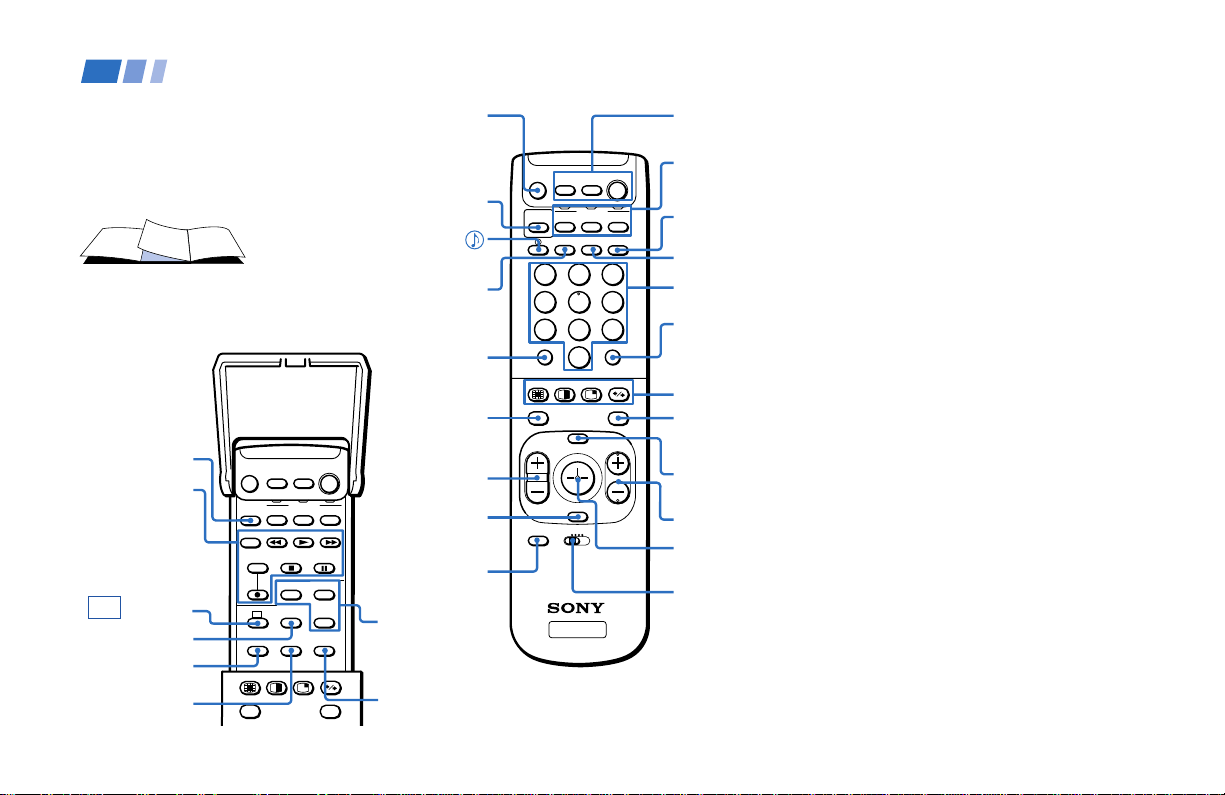
Remote Control
In the instructions that follow, we will
refer to the buttons on your remote control.
Keep this flap unfolded and use this page
for reference.
SYSTEM OFF
(page 27)
VCR/DVD/MDP
operation
buttons
(page 56)
CC (page 27)
SLEEP(page 27)
MTS/SAP
(pages 27, 35)
SWAP
(pages 29, 31)
SYSTEM
OFF
TV/VTR
MTS/SAP
AUDIO
INDEX
REC
DVD/
SAT/
VTR
CABLE
FUNCTION
DVD/VTR SAT/CABLE
AUDIO DVD MENU
SLEEPCCTITLE
SWAP
POWERMUTING
POSITION
ACTIVE
FREEZE
GUIDE
TV
TV
MUTING
(page 25)
PICTURE
MODE
(pages 25, 34)
(pages 27, 35)
DISPLAY
(page 26)
JUMP
(page 26)
AUDIO
(
pages 29, 31)
(
INDEX
for SAT, page 57)
VOL +/–
(page 25)
RESET
(pages 28,
34, 35)
CODE SET
(pages 55, 57)
DVD
operation
buttons
(page 56)
POSITION
(page 28)
/
DVD/
SAT/
VTR
CABLE
FUNCTION
PICTURE
DVD/VTR SAT/CABLE
MODE
DISPLAY ANT TV/VIDEO
1
2
4
5
7
8
0
INDEX
MENU
VOL CH
RESET
VTR123DVD/MDP
CODE SET
TV
ENTERJUMP
POWERMUTING
3
6
9
ACTIVE
FREEZEAUDIO
GUIDE
POWER
(pages 25, 56, 57)
FUNCTION
TV
TV
(pages 25, 55-57)
TV/VIDEO
(page 26)
ANT
(page 27)
0–9 buttons
(page 25)
ENTER
(page 25)
CHANNEL INDEX/
PIP/P&P/ACTIVE
(pages 28-32)
FREEZE (pages 26,
29, 31, 32)/
(page 57)
GUIDE
MENU (page 33)
CH +/– (page 25)
Joystick
(page 22)
VTR 1/2/3/
DVD/MDP
(pages 43, 55,
56)
Getting to know the buttons on the
remote control
Names of the buttons on the remote control are
presented in different colors to represent the
available functions.
Button color
Black ................ Press to select the component
Green ............... Buttons relevant to power
Label color
White ............... TV/VTR (VCR)/MDP/DVD
Yellow.............. PIP, P&P, and CHANNEL
Blue .................. SAT operation buttons
Green ............... S-Link operation buttons
Pink .................. DVD Player operation buttons
you want to control; e.g. VTR
(VCR)/MDP/DVD Player,
SAT (satellite receiver)/
CABLE, or projection TV.
operations, like turning the
projection TV, SAT/CABLE, or
VTR (VCR)/MDP/DVD Player
on or off
Player/SAT
(satellite receiver)
CABLE operation buttons
INDEX operation buttons
/
For a detailed explanation of most buttons, see
“Watching the TV” on page 25.
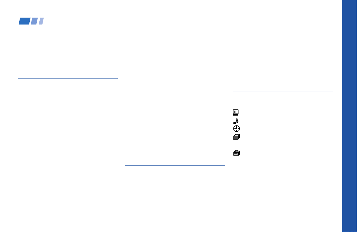
Table of Contents
Welcome! ........................................ 1
Using This Manual .......................... 2
Precautions...................................... 2
Important Safeguards .................... 3
Installing and Connecting the
Projection TV....................... 7
Carrying Your Projection TV......................7
Installing the Projection TV........................ 7
Connector Types .......................................... 8
Making Connections ...................................8
Connecting directly to a cable or an
antenna ............................................... 8
Cable or antenna.................................... 9
Cable and antenna................................. 9
Connecting a cable box .........................9
Cable box and cable ..............................9
Connecting a cable TV system/
antenna to a VCR ............................ 10
Connecting a VCR and projection TV
to a cable box ...................................10
Connecting a satellite receiver (SAT) 11
Connecting a satellite receiver (SAT)
and a VCR ........................................ 12
Connecting a DTV (digital television)
receiver .............................................13
Connecting a camcorder.....................14
Connecting two VCRs for tape
editing ............................................... 15
Connecting a DVD Player ..................16
Connecting a DVD Player with
component video output
connectors ........................................ 16
Connecting an AV receiver.................17
Connecting an audio system ............. 18
Connecting a Sony SAVA series
speaker system ................................ 18
Connecting an amplifier that supports
Dolby Pro Logic decoder ............... 19
Using the S-Link Function........................ 20
Using the S-Link function without a
Sony AV receiver ............................. 20
Using the S-Link function with
a Sony AV receiver ..........................21
Basic Set Up................................... 22
Using the Remote Control ........................22
Setting Up the Projection TV Automati-
cally ....................................................23
Adjusting the Convergence Automatically
(FLASH FOCUS) ..............................24
Using Your New Projection TV .... 25
Watching the TV ........................................ 25
Watching Two Programs at One Time
— PIP ................................................. 28
Watching Two Programs at One Time
— P&P (Twin ViewTM) ..................... 30
Using CHANNEL INDEX ........................32
Adjusting Your SET UP (menus)... 33
Learning Menu Selection .......................... 33
Using the Video Menu.........................34
Using the Audio Menu ........................ 35
Using the Timer Menu........................37
ch
Using the Channel Set Up Menu ......38
Setting and Selecting Favorite Channel..40
Using the Set Up Menu ......................42
Using the Parental Control Feature.........44
Activating the Parental Control
Feature ..............................................44
Selecting a Custom Rating in
U.S.A. ................................................46
Selecting a Custom Rating
in Canada .........................................49
Changing the Password ..................... 50
Open Here For Table of Contents and Remote Control Graphics
Welcome!
What the Ratings Mean ............................... 51
Ratings in U.S.A.................................. 51
Ratings in Canada .............................. 53
Operating Video Equipment........... 55
Setting the Manufacturer's Code ................ 55
Operating a Cable Box or Satellite
Receiver (SAT)........................... 57
Setting the Manufacturer's Code ................ 57
Troubleshooting .............................. 58
Specifications ................................... 60
Index................................................. 61
Owner’s Record
The model and serial numbers are located at the rear of
the projection TV, below the Sony logo, on the sticker,
and also on the TV box (white label). Record these numbers
in the spaces provided below. Refer to them whenever
you call upon your Sony dealer regarding this product.
Model No.
Serial No.
Thank you for purchasing the Sony Color
Rear Video Projection TV.
This manual is for models KP-48V85, KP53V85 and KP-61V85.
Model KP-53V85 is used for illustration
purposes.
The features you will enjoy include:
• FLASH FOCUS, allowing you to adjust
convergence automatically.
• Parental Control, enabling you to block
programs that you feel are unsuitable for
your children.
• Picture & Picture (P&P) (Twin View
TM
),
allowing you to view two channels
simultaneously both in a reduced size.
• Picture-in Picture (PIP), allowing you to
view another TV channel, video or cable
image as a window picture.
• CHANNEL INDEX, allowing you to view
and choose from twelve programs
• Favorite Channel, allowing you to
view and choose from eight of your
favorite channels
• S-Link
TM
, allowing you to control some
operations of your projection TV by other
Sony components.
• Two Y/P B/PR inputs for DVD Player and
DTV receiver connections.
• Three AUDIO/VIDEO/S VIDEO inputs.
Manufactured under license from Dolby
Laboratories Licensing Corporation.
Additionally licensed under Canadian patent
number 1,037,877. “Dolby,” the double-D symbol
a, “Pro Logic,” “VIRTUAL DOLBY and
DIGITAL”are trademarks of Dolby Laboratories
Licensing Corporation.
SRS (r) (SOUND RETRIEVAL SYSTEM)
The SRS (r) (SOUND RETRIEVAL SYSTEM) is
manufactured by Sony Corporation under license
from SRS Labs, Inc. It is covered by U.S. Patent
No. 4,748,669. Other U.S. and foreign patents
pendeing.
The word SRS and the SRS symbol (r) are
registered trademarks of SRS Labs, Inc.
1

Using This Manual
Installing and Connecting the Projection TV (continued)
Precautions
We recommend that you carefully review
the contents of the following four sections in
the order provided to ensure that you fully
understand the operation of your new
projection TV.
1 Installing and Connecting the Projection
TV
This section guides you through your
initial set up. It shows you how to install
your projection TV, to connect your new
components and to connect to the
antenna and cable.
2 Basic Set Up
This section teaches you the basic skills
needed to operate your new projection
TV, including Auto Set Up. It shows you
how to operate the remote control’s
special functions.
3 Using Your New Projection TV
This section shows you how to begin
using your new projection TV. It shows
you how to use your remote control’s
features.
4 Adjusting Your Set Up (menus)
This section teaches you how to access
on-screen menus and adjust your
projection TV’s settings.
Instructions in this manual are written for the remote
control. Similar controls may be found on the projection
TV console.
Safety
• Operate the projection TV only on 120 V
AC.
• The plug is designed, for safety purposes,
to fit into the wall outlet only one way. If
you are unable to insert the plug fully into
the outlet, contact your dealer.
• If any liquid or solid object should fall
inside the cabinet, unplug the projection
TV immediately and have it checked by
qualified service personnel before
operating it further.
• If you will not be using the projection TV
for several days, disconnect the power by
pulling the plug itself. Never pull on the
cord.
Note on cleaning
Clean the cabinet of the projection TV with a
dry soft cloth. To remove dust from the
screen, wipe it gently with a soft cloth.
Stubborn stains may be removed with a cloth
slightly dampened with solution of mild soap
and warm water. Never use strong solvents
such as thinner or benzine for cleaning.
If the picture becomes dark after using the
projection TV for a long period of time, it may
be necessary to clean the inside of the
projection TV. Consult qualified service
personnel.
Installing
• To prevent internal heat buildup, do not
block the ventilation openings.
• Do not install the projection TV in a hot
or humid place, or in a place subject to
excessive dust or mechanical vibration.
• Avoid operating the projection TV at
temperatures below 5° C (41° F).
• If the projection TV is transported
directly from a cold to a warm location,
or if the room temperature changes
suddenly, the picture may be blurred or
show poor color. In this case, please wait
a few hours to let the moisture evaporate
before turning on the projection TV.
• To obtain the best picture, do not expose
the screen to direct illumination or direct
sunlight. It is recommended to use spot
lighting directed down from the ceiling
or to cover the windows that face the
screen with opaque drapery. It is
desirable to install the projection TV in a
room where the floor and walls are not of
a reflective material.
2
Important Safeguards
For your protection, please read these
instructions completely, and keep this
manual for future reference.
Carefully observe and comply with all
warnings, cautions and instructions placed
on the set, or described in the operating
instructions or service manual.
WARNING
To guard against injury, the following basic
safety precautions should be observed in the
installation, use, and servicing of the set.
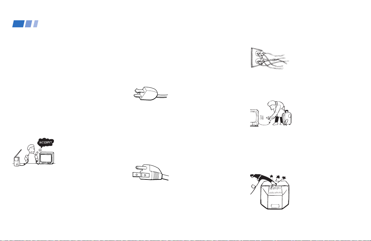
Use
Power Sources
This set should be
operated only from the
type of power source
indicated on the serial/
model plate.
If you are not sure of the type of electrical
power supplied to your home, consult your
dealer or local power company. For those
sets designed to operate from battery power,
refer to the operating instructions.
Grounding or Polarization
This set is equipped with a polarized AC
power cord plug (a plug having one blade
wider than the other), or with a three-wire
grounding type plug (a plug having a third
pin for grounding).
Follow the instructions below:
For the set with a
polarized AC power
cord plug
This plug will fit into the power outlet only
one way. This is a safety feature. If you are
unable to insert the plug fully into the outlet,
try reversing the plug. If the plug should still
fail to fit, contact your electrician to have a
suitable outlet installed. Do not defeat the
safety purpose of the polarized plug by
forcing it in.
Alternate Warning
For the set with a
three-wire grounding
type AC plug
This plug will only fit into a grounding-type
power outlet. This is a safety feature. If you
are unable to insert the plug into the outlet,
contact your electrician to have a suitable
outlet installed. Do not defeat the safety
purpose of the grounding plug.
Overloading
Do not overload wall
outlets, extension cords or
convenience receptacles
beyond their capacity,
since this can result in fire
or electric shock.
Always turn the set off
when it is not to be used.
When the set is left
unattended and unused
for long periods of time,
unplug it from the wall
outlet as a precaution
against the possibility of
an internal malfunction
that could create a fire
hazard.
Object and Liquid
Entry
Never push objects of any
kind into the set through
the cabinet slots as they
may touch dangerous
voltage points or short out
parts that could result in a
fire or electric shock.
Never spill liquid of any kind on the set.
(continued)
3
Installing and Connecting the Projection TV (continued)
Important Safeguards (continued)
Attachments
Do not use attachments
not recommended by the
manufacturer, as they
may cause hazards.
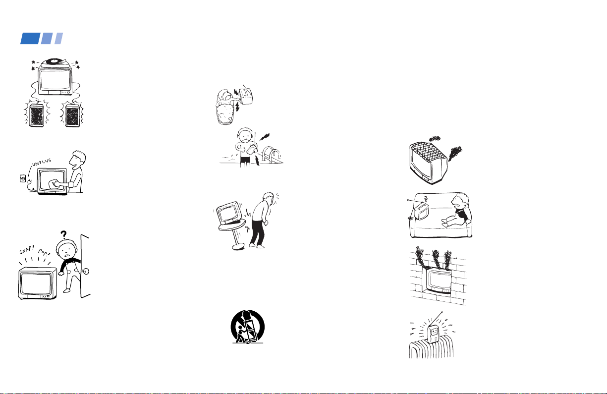
Cleaning
Unplug the set from the
wall outlet before
cleaning or polishing it.
Do not use liquid cleaners
or aerosol cleaners. Use a
cloth lightly dampened
with water for cleaning
the exterior of the set.
If a snapping or popping
sound from a projection
TV set is continuous or
frequent while the
projection TV is
operating, unplug the
projection TV and consult
your dealer or service
technician.
It is normal for some projection TV sets to
make occasional snapping or popping
sounds, particularly when being turned on or
off.
4
Installation
Water and Moisture
Do not use power-line
operated sets near
water— for example, near
a bathtub, washbowl,
kitchen sink, or laundry
tub, in a wet basement or
near a swimming pool,
etc.
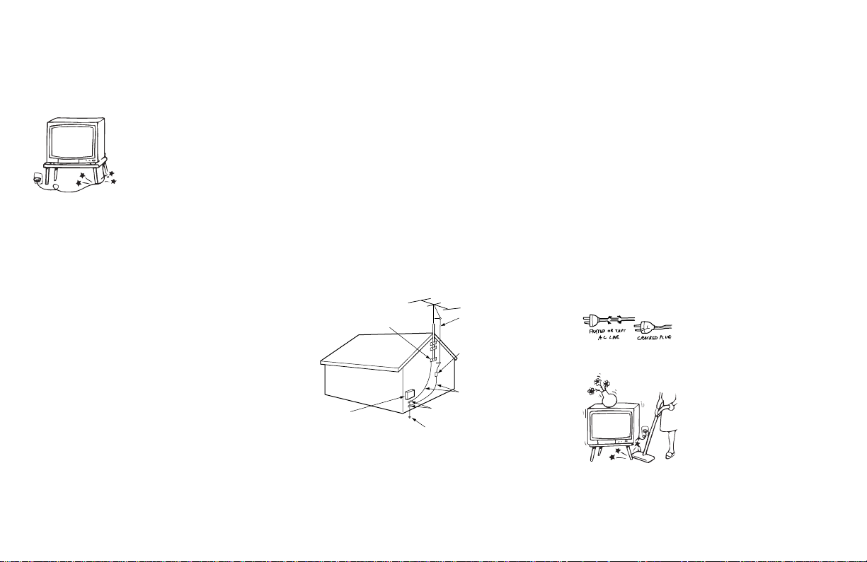
Accessories
Do not place the set on an
unstable cart, stand, table
or shelf. The set may fall,
causing serious injury to a
child or an adult, and
serious damage to the set.
Use only a cart or stand recommended by the
manufacturer for the specific model of
projection TV.
An appliance and cart
combination should be
moved with care. Quick
stops, excessive force, and
uneven surfaces may
cause the appliance and
cart combination to
overturn.
Ventilation
The slots and openings in the cabinet and in
the back or bottom are provided for
necessary ventilation. To ensure reliable
operation of the set, and to protect it from
overheating, these slots and openings must
never be blocked or covered.
- Never cover the slots
and openings with a cloth
or other materials.
- Never block the slots
and openings by placing
the set on a bed, sofa, rug
or other similar surface.
- Never place the set in a
confined space, such as a
bookcase, or built-in
cabinet unless proper
ventilation is provided.
- Do not place the set near
or over a radiator or heat
register, or where it is
exposed to direct
sunlight.
Power-Cord
Protection
Do not allow anything to
rest on or roll over the
power cord, and do not
place the set where the
power cord is subject to
wear or abuse.
Antennas
Outdoor Antenna Grounding — If an
outdoor antenna is installed, follow the
precautions below.
An outdoor antenna system should not be
located in the vicinity of overhead power
lines or other electric light or power circuits,
or where it can come in contact with such
power lines or circuits.
WHEN INSTALLING AN OUTDOOR
ANTENNA SYSTEM, EXTREME CARE
SHOULD BE TAKEN TO KEEP FROM
CONTACTING SUCH POWER LINES OR
CIRCUITS AS CONTACT WITH THEM IS
ALMOST INVARIABLY FATAL.
Be sure the antenna system is grounded so as
to provide some protection against voltage
surges and built-up static charges.
Section 810 of the National Electrical Code
(NEC) in USA and Section 54 of the
Canadian Electrical Code in Canada provides
information with respect to proper
grounding of the mast and supporting
structure, grounding of the lead-in wire to an
antenna discharge unit, size of grounding
conductors, location of antenna discharge
unit, connection to grounding electrodes, and
requirements for the grounding electrode.
Antenna Grounding According to the
NEC — Refer to section 54-300 of Canadian
Electrical Code for Antenna Grounding.
Ground clamp
Electric service
equipment
NEC: National
Electrical Code
Antenna lead-in
wire
Antenna discharge
unit (NEC Section
810-20)
Grounding
conductors (NEC
Section 810-21)
Ground clamps
Power service grounding
electrode system (NEC
Art 250 Part H)
Lightning
For added protection for this television
receiver during a lightning storm, or when it
is left unattended and unused for long
periods of time, unplug it from the wall
outlet and disconnect the antenna. This will
prevent damage to the receiver due to
lightning and power-line surges.
Service
Damage Requiring Service
Unplug the set from the wall outlet and refer
servicing to qualified service personnel
under the following conditions:
- When the power cord or
plug is damaged or
frayed.
- If liquid has been spilled
into the set.
(continued)
5
Installing and Connecting the Projection TV (continued)
Important Safeguards (continued)
- If the set has been
exposed to rain or water.
- If the set has been
subject to excessive shock
by being dropped, or the
cabinet has been
damaged.
- If the set does not
operate normally when
following the operating
instructions. Adjust only
those controls that are
specified in the operating
instructions.
Improper adjustment of
other controls may result
in damage and will often
require extensive work by
a qualified technician to
restore the set to normal
operation.
- When the set exhibits a distinct change in
performance—this indicates a need for
service.
6
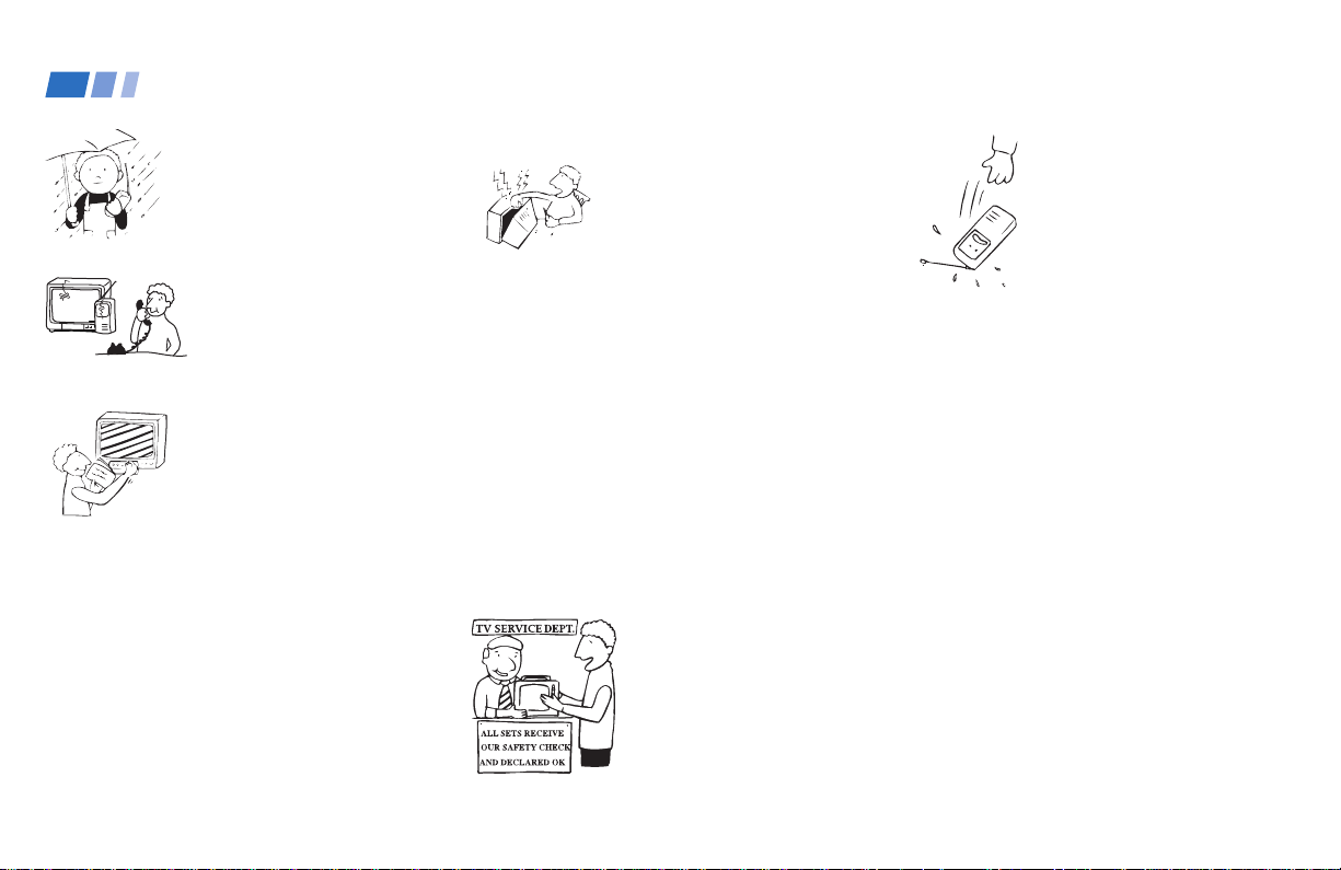
Servicing
Do not attempt to service
the set yourself since
opening the cabinet may
expose you to dangerous
voltage or other hazards.
Refer all servicing to
qualified service
personnel.
Replacement Parts
When replacement parts are required, be
sure the service technician certifies in writing
that he has used replacement parts specified
by the manufacturer that have the same
characteristics as the original parts.
Unauthorized substitutions may result in
fire, electric shock, or other hazards.
Safety Check
Upon completion of any
service or repairs to the
set, ask the service
technician to perform
routine safety checks (as
specified by the
manufacturer) to
determine that the set is
in safe operating
condition, and to so
certify.
When the set reaches the
end of its useful life,
improper disposal could
result in a picture tube
implosion. Ask a
qualified service
technician to dispose of
the set.
Installing and Connecting the Projection TV
Carrying Your Projection TV
Carrying the projection TV requires three or
more people.
The projection TV has been equipped with
casters for easy movement on a hard surface.
Please move your projection TV using the
casters.
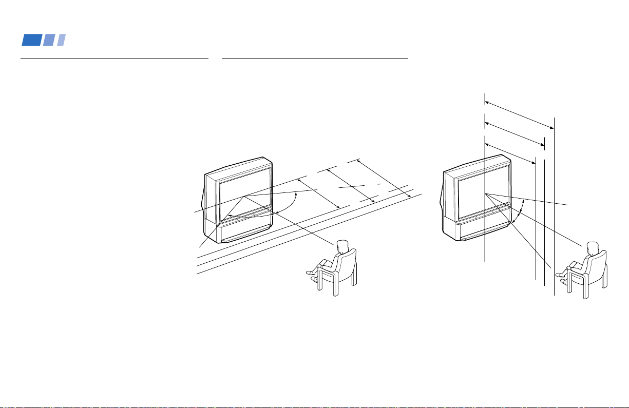
Installing the Projection TV
Recommended viewing area
(Horizontal)
min. 2.4m (approx. 8 ft.)
min. 2.1m (approx. 7 ft.)
60°
60°
min. 1.8m (approx. 6 ft.)
48"
60°
61"
53"
Recommended viewing area
(Vertical)
min. 2.4m (approx. 8ft.)
61"
min. 2.1m (approx. 7ft.)
53"
min. 1.8m (approx. 6ft.)
48"
20°
20°
7
Installing and Connecting the Projection TV (continued)
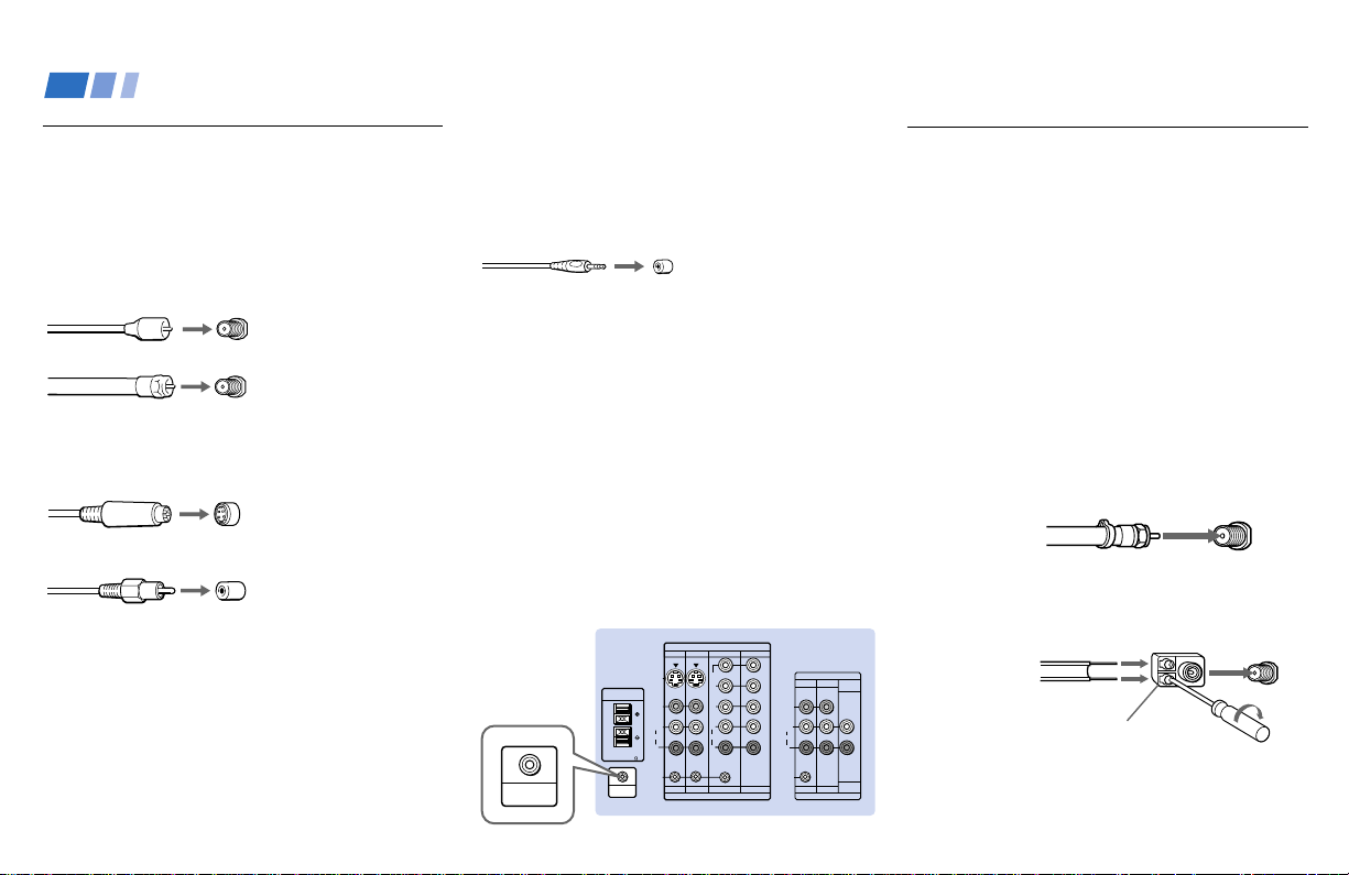
Connector Types
You may find it necessary to use some of the
following connector types during set up.
Coaxial cable
Standard TV cable and antenna cable
Plug Type
Push into connection.
Screw-on Type
Screw into connection.
S Video cable
High quality video cable for enhanced
picture quality
Audio/Video cable
Video - Yellow
Audio (Left) - White
Audio (Right) - Red
Some DVD Players and DTV Receivers are
equipped with the following three video
connectors.
Y - Green
P
B (CB, Cb or B–Y) - Blue
P
R (CR, Cr or R–Y) - Red
8
Align guides and
push into connection.
Push into connection.
S-Link/CONTROL S cable
Sony cable for S-Link and CONTROL S
connections. These features are exclusive to
Sony products and allow greater control of
all Sony equipment.
Push into connection.
Note:
• For S-Link and CONTROL S connections,
you can use the combined S-Link/
CONTROL S cable provided with some
Sony video equipment, or you can purchase
a separate S-Link/CONTROL S cable (RKG69HG).
About the CONTROL S OUT jack
To control other Sony equipment with the
projection TV's remote control, connect the
CONTROL S IN jack of the equipment to the
CONTROL S OUT jack on the projection TV
with the CONTROL S cable.
(Rear of
projection TV)
CONTROL S
OUT
CENTER SPEAKER
IN
40W(NOM)
80W(MAX)16
CONTROL S
OUT
S VIDEO
VIDEO
AUDIO
S-LINK
IN
VIDEO 1 VIDEO 3 VIDEO 4
Y
P
B
P
R
L
L
(MONO)
AUDIO
R
R
VIDEO 1 VIDEO 3 VIDEO 4 VIDEO 5
IN
VIDEO 5
OUT
MONITOR
AUDIO
TV
(VAR/FIX)
VIDEO
L
(MONO)
AUDIO
R
S-LINK
AUDIO
(VAR/FIX)
MONITOR
TV
OUT
Making Connections
Connecting directly to a cable or an antenna
The connection you choose will depend on
the cable found in your home. Newer homes
will be equipped with standard coaxial cable
(see
A); older homes will probably have 300-
ohm twin lead cable (see B); still other homes
may contain both (see
Use 75-ohm coaxial cable for improved
picture quality (see
A
• VHF only
or
• VHF/UHF
or
• Cable
B
• VHF only
or
• UHF only
or
• VHF/UHF
Antenna connector
C).
A).
75-ohm
coaxial cable
300-ohm twin
lead cable
(Rear of
projection TV)
VHF/UHF
(Rear of
projection TV)
VHF/UHF
C
75-ohm coaxial cable
• VHF
and
• UHF
300-ohm twin lead cable
(Rear of
projection TV)
VHF/UHF
EAC-66 U/V mixer
(not supplied)
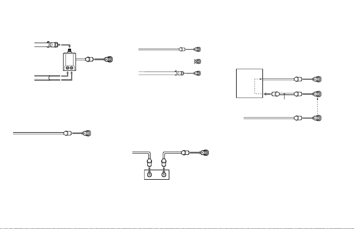
Cable or antenna
This is the simplest connection. Connection is
made directly from the cable or antenna to
the projection TV.
(Rear of projection TV)
Coaxial cable
VHF/UHF
Cable and antenna
You may find it convenient to use the
following set up if your cable provider does
not feature local channels that you are able to
receive using an antenna.
(Rear of projection TV)
Coaxial cable
(No connection “TO
CONVERTER” in this case)
Antenna cable
AUX
TO CONVERTER
VHF/UHF
Select Cable or ANT mode by pressing ANT
on the remote control.
Connecting a cable box
Some pay cable TV systems use scrambled or
encoded signals that require a cable box* to
view all channels.
Also, set “Cable” to “On” in the Channel Set
Up menu (page 39).
(Rear of projection TV)
Coaxial cable
OUTIN
*Cable box
VHF/UHF
Cable box and cable
Some pay cable TV systems use scrambled or
encoded signals requiring a cable box* only for
certain channels (e.g. HBO, SHOWTIME, etc.)
*Cable box
Scrambled
channels
75-ohm coaxial cable
(not supplied)
CATV cable
(unscrambled channels)
For this set up, you can switch between
scrambled channels (through your cable box),
and normal (CATV) channels by pressing
ANT on your remote control.
Notes:
• You may be able to program your Sony
remote control to operate your cable box.
(see “Operating a Cable Box or Satellite
Receiver (SAT)” on page 57)
• During PIP, P&P, CHANNEL INDEX or
Favorite Channel viewing, the AUX input
can only be viewed in the main picture.
(Rear of projection TV)
AUX
TO CONVERTER
(Signal)
VHF/UHF
9
Installing and Connecting the Projection TV (continued)
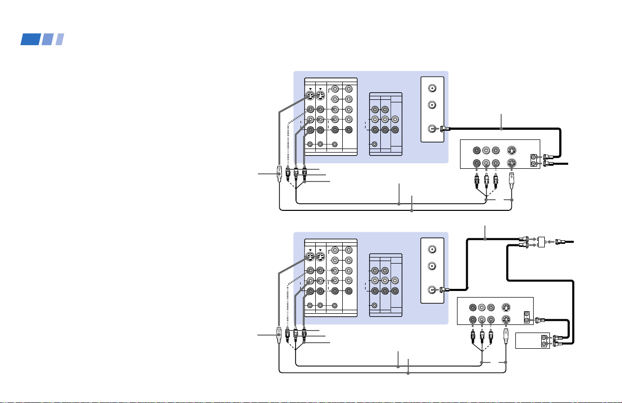
Connecting a cable TV system/ antenna to a VCR
1 Attach the coaxial cable from the
incoming cable connection or antenna to
VHF/UHF IN on the VCR.
2 Using a coaxial cable, connect VHF/UHF
OUT on the VCR to VHF/UHF on the
projection TV.
3 Using AUDIO and S VIDEO* cables,
connect AUDIO and S VIDEO OUT on the
VCR to AUDIO and S VIDEO IN on the
projection TV (White-AUDIO Left, RedAUDIO Right**).
Connecting a VCR and projection TV to a cable box
1 Connect the single (input) jack of the
splitter to the incoming cable connection,
and connect the other two (output) jacks
(using the coaxial cable) to IN on the cable
box and VHF/UHF on the projection TV.
2 Using a coaxial cable, connect OUT on the
cable box to VHF/UHF IN on the VCR.
3 Using AUDIO and S VIDEO* cables,
connect AUDIO and S VIDEO OUT on the
VCR to AUDIO and S VIDEO IN on the
projection TV (White-AUDIO Left, RedAUDIO Right**).
10
S VIDEO
S VIDEO
VIDEO 1 VIDEO 3 VIDEO 4
S VIDEO
VIDEO
L
(MONO)
AUDIO
R
S-LINK
VIDEO 1 VIDEO 3 VIDEO 4 VIDEO 5
VIDEO
VIDEO 1 VIDEO 3 VIDEO 4
S VIDEO
VIDEO
L
(MONO)
AUDIO
R
S-LINK
VIDEO 1 VIDEO 3 VIDEO 4 VIDEO 5
VIDEO
Disconnect all power sources before making any connections.
(Rear of projection TV)
IN
VIDEO 5
Y
P
B
PR
L
AUDIO
R
IN
AUDIO-L
AUDIO-R
OUT
MONITOR
TV
VIDEO
L
(MONO)
AUDIO
R
S-LINK
MONITOR
TV
OUT
AUDIO
(VAR/FIX)
AUDIO
(VAR/FIX)
VMC-810S/820S
(not supplied)
(Rear of projection TV)
IN
VIDEO 5
Y
B
P
P
R
L
AUDIO
R
IN
AUDIO-L
AUDIO-R
OUT
MONITOR
TV
VIDEO
L
(MONO)
AUDIO
R
S-LINK
MONITOR
TV
OUT
AUDIO
(VAR/FIX)
AUDIO
(VAR/FIX)
VMC-810S/820S
(not supplied)
AUX
TO
CONVERTER
VHF/UHF
YC-15V/30V
(not supplied)
AUX
TO
CONVERTER
VHF/UHF
YC-15V/30V
(not supplied)
2
AUDIO R AUDIO L VIDEO
LINE
IN
LINE
OUT
Coaxial cable
AUDIO R AUDIO L VIDEO
LINE
IN
LINE
OUT
Coaxial cable
VCR
S VIDEO
VHF/UHF
OUT
IN
3
VCR
S VIDEO
VHF/UHF
OUT
IN
Cable box
3
Cable/
Antenna
1
1
Splitter
(not supplied)
2
OUT
IN
Cable/
Antenna
Note:
• To view scrambled channels through the
cable box, select the video input which the
cable box is connected to by pressing TV/
VIDEO.
* If your VCR is not equipped with S VIDEO, use a
VIDEO cable (yellow) instead of the S VIDEO
cable.
** If you are connecting a monaural VCR, connect
only the single audio output to the left (MONO)
input on the projection TV.
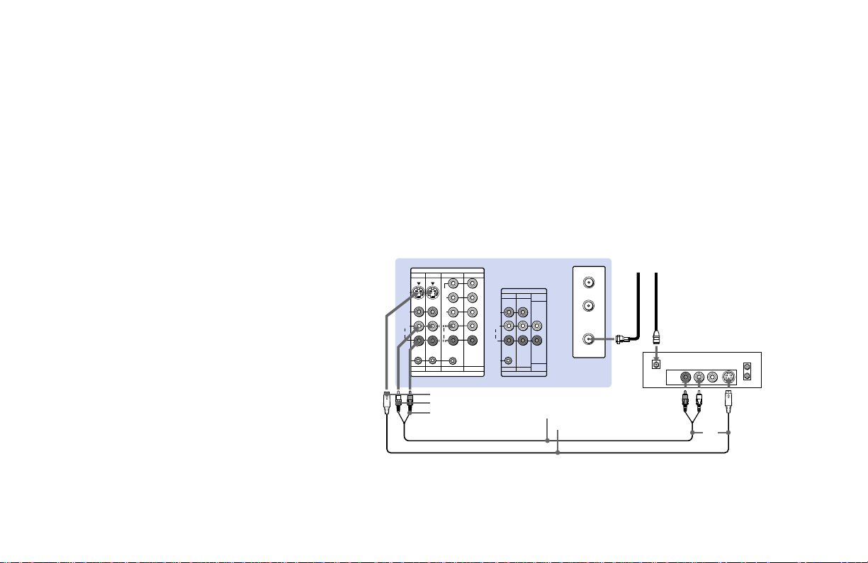
Connecting a satellite receiver (SAT)
1 Connect the cable from the satellite
antenna to the satellite receiver.
2 Attach the coaxial cable from the incoming
cable connection or antenna to VHF/UHF
on the projection TV.
3 Using AUDIO and S VIDEO cables,
connect AUDIO and S VIDEO OUT on the
satellite receiver to AUDIO and S VIDEO
IN on the projection TV (White-AUDIO
Left, Red-AUDIO Right).
Note:
• To view input from the satellite receiver,
select the video input which the satellite
receiver is connected to by pressing TV/
VIDEO on the remote control.
VIDEO 1 VIDEO 3 VIDEO 4
S VIDEO
VIDEO
L
(MONO)
AUDIO
R
S-LINK
VIDEO 1 VIDEO 3 VIDEO 4 VIDEO 5
S VIDEO
AUDIO-L
AUDIO-R
Disconnect all power sources before making any connections.
(Rear of projection TV)
IN
VIDEO 5
Y
P
B
PR
L
AUDIO
R
IN
OUT
MONITOR
AUDIO
TV
(VAR/FIX)
VIDEO
L
(MONO)
AUDIO
R
S-LINK
AUDIO
(VAR/FIX)
MONITOR
TV
OUT
RK-74A (not supplied)
YC-15V/30V (not supplied)
AUX
TO
CONVERTER
VHF/UHF
Cable/
Antenna
SATELLITE IN
LINE OUT
Satellite antenna
cable
12
AUDIO R AUDIO L VIDEO
S VIDEO
VHF/UHF
SAT
IN
OUT
3
11
Installing and Connecting the Projection TV (continued)
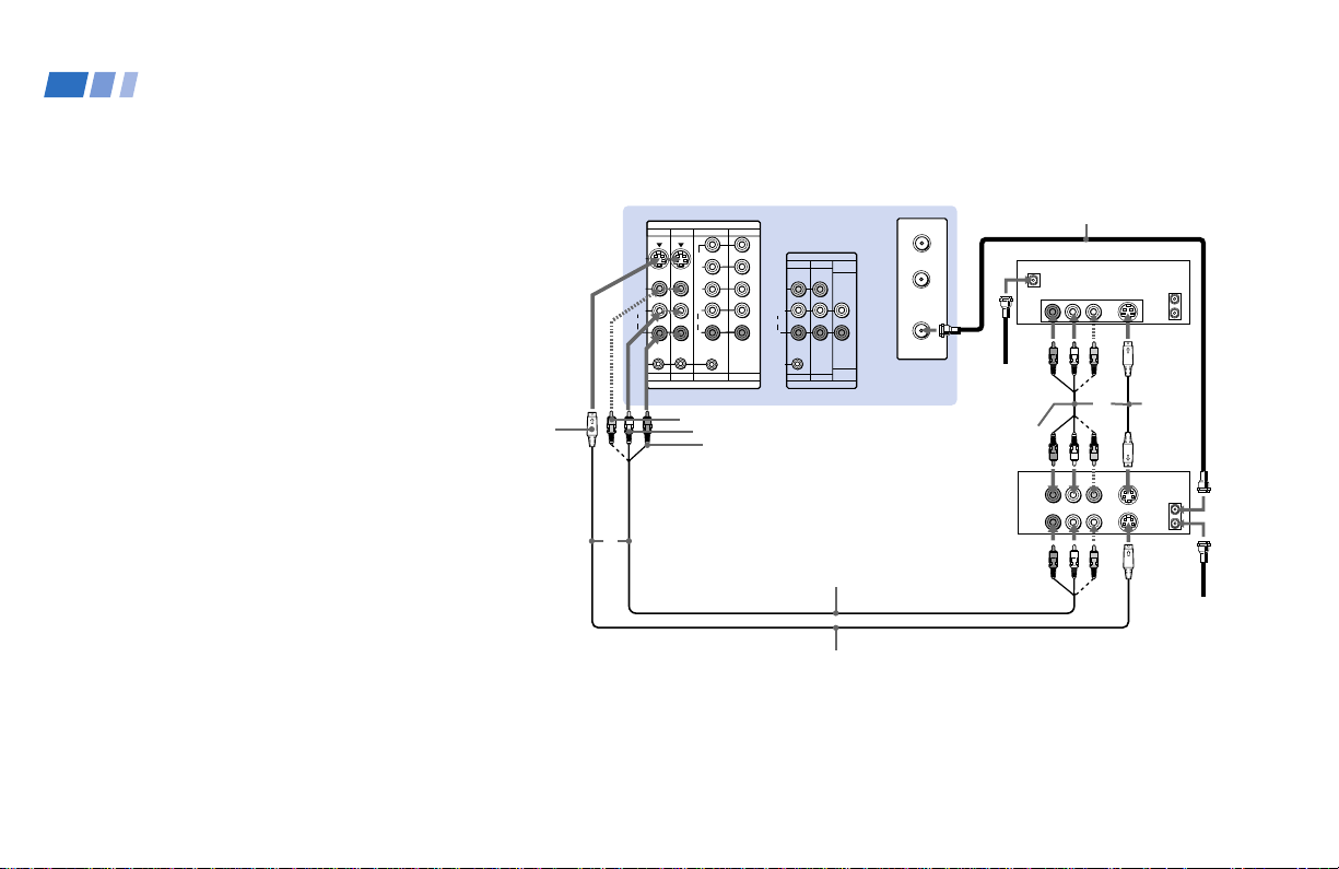
Connecting a satellite receiver (SAT) and a VCR
1 Connect the cable from the satellite
antenna to the satellite receiver.
2 Attach the coaxial cable from the
incoming cable connection or antenna to
VHF/UHF IN on the VCR.
3 Using a coaxial cable, connect VHF/UHF
OUT on the VCR to VHF/UHF on the
projection TV.
4 Using AUDIO and S VIDEO* cables,
connect AUDIO and S VIDEO OUT on the
satellite receiver to AUDIO and S VIDEO
IN on the VCR.
5 Using AUDIO and S VIDEO* cables,
connect AUDIO and S VIDEO OUT on the
VCR to AUDIO and S VIDEO IN on the
projection TV (White-AUDIO Left, RedAUDIO Right).
*
If your VCR is not equipped with S VIDEO, use a
VIDEO cable (yellow) instead of the S VIDEO
cable.
Note:
• To view input from the satellite receiver or
VCR, select the video input which your
satellite receiver or VCR is connected to
by pressing TV/VIDEO on the remote
control.
12
S VIDEO
VIDEO 1 VIDEO 3 VIDEO 4
S VIDEO
VIDEO
L
(MONO)
AUDIO
R
S-LINK
VIDEO 1 VIDEO 3 VIDEO 4 VIDEO 5
5
Disconnect all power sources before making any connections.
(Rear of projection TV)
IN
VIDEO 5
Y
P
B
P
R
L
AUDIO
R
IN
VIDEO
AUDIO-L
AUDIO-R
OUT
MONITOR
AUDIO
TV
(VAR/FIX)
VIDEO
L
(MONO)
AUDIO
R
S-LINK
AUDIO
(VAR/FIX)
MONITOR
TV
OUT
VMC-810S/820S (not supplied)
YC-15V/30V (not supplied)
3
AUX
TO
CONVERTER
VHF/UHF
1
Satellite
antenna
cable
VMC-810S/820S
(not supplied)
VCR
Coaxial cable
SATELLITE IN
AUDIO R AUDIO L VIDEO
LINE
OUT
AUDIO R AUDIO L VIDEO
LINE
IN
LINE
OUT
SAT
VHF/UHF
S VIDEO
OUT
IN
YC-15V/
30V
4
(not
supplied)
S VIDEO
VHF/UHF
OUT
IN
Cable/
Antenna
2
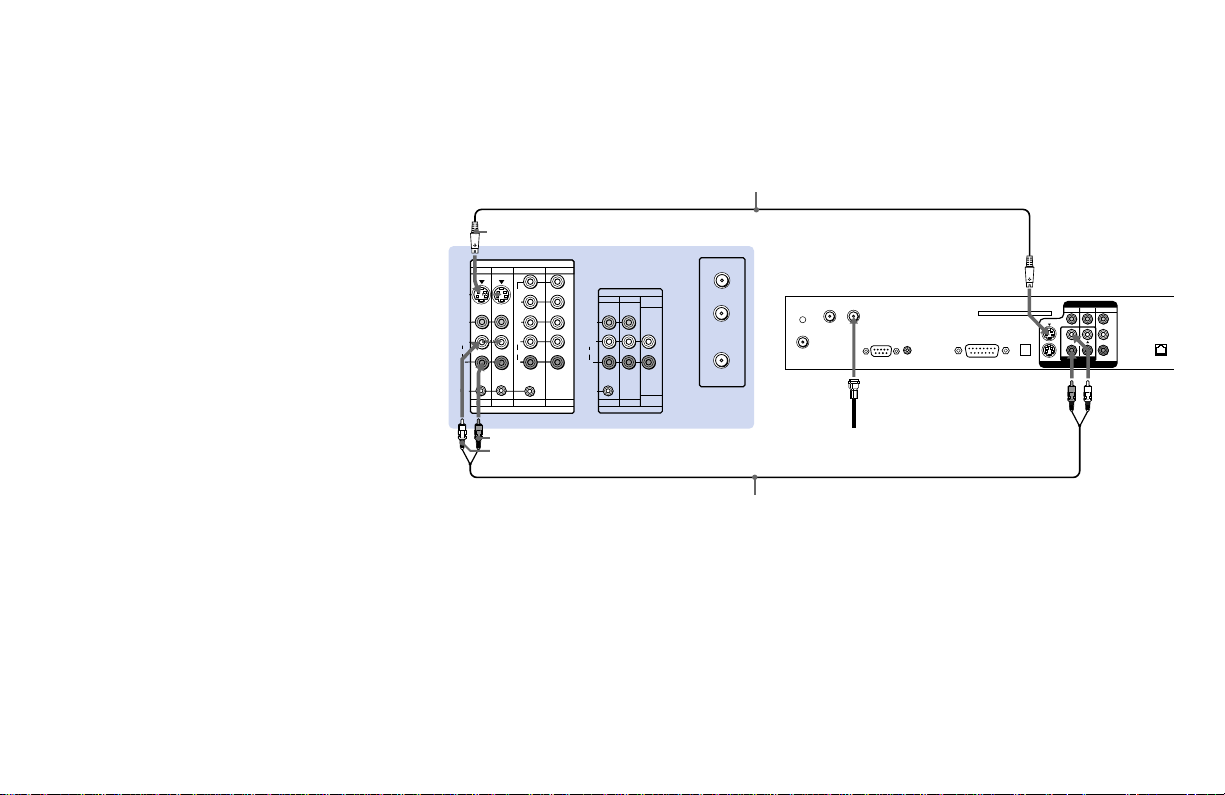
Connecting a DTV (digital television) receiver
Before connecting, be sure to read the
Operating Instructions of the DTV receiver.
1 Attach the coaxial cable from the roof
antenna to VHF/UHF IN (DTV) on the
DTV receiver.
2 Using AUDIO and S VIDEO cables, connect
AUDIO and S VIDEO OUT on the DTV
receiver to AUDIO and S VIDEO IN on the
projection TV (White-AUDIO Left, RedAUDIO Right).
Note:
• If your DTV receiver supports 480i signal
from YP
of VIDEO OUT on the DTV receiver to Y,
PB and PR of VIDEO 4 or 5 IN on the
projection TV using VIDEO cables.
BPR, you can connect Y, PB and PR
S VIDEO
IN
VIDEO 1 VIDEO 3 VIDEO 4
S VIDEO
VIDEO
L
(MONO)
AUDIO
R
S-LINK S-LINK
VIDEO 1 VIDEO 3 VIDEO 4 VIDEO 5
VIDEO 5
Y
P
B
PR
L
AUDIO
R
IN
AUDIO-R
AUDIO-L
Disconnect all power sources before making any connections.
YC-15V/30V (not supplied)
(Rear of projection TV)
AUX
OUT
MONITOR
AUDIO
TV
(VAR/FIX)
VIDEO
L
(MONO)
AUDIO
R
AUDIO
(VAR/FIX)
MONITOR
TV
OUT
TO
CONVERTER
VHF/UHF
RK-74A (not supplied)
DTV receiver
VHF/UHF IN
VHF/UHF IN (DTV)
SATELLITE IN
VHF/SATELLITE
OUT
LOW SPEED DATA
1
Roof antenna
VCR
CONTROL
VGA OUT
ACCESS CARD
DIGITAL
AUDIO
OUT
(OPTICAL)
2
S VIDEO
AUDIO/VIDEO OUT
VIDEO
123
L
MONO
R
AUDIO
Y
B
P
PR
TEL LINE
2
13
Installing and Connecting the Projection TV (continued)
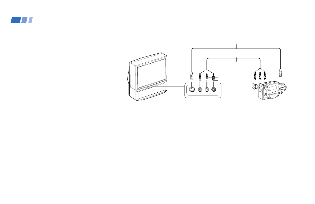
Connecting a camcorder
Use this connection to view a picture directly
from your camcorder.
1 Using AUDIO and S VIDEO* cables,
connect AUDIO and S VIDEO OUT on
the camcorder to AUDIO and S VIDEO
IN inside the drop-down panel on the
front of the projection TV (White-AUDIO
Left, Red-AUDIO Right**).
2 Press VIDEO 2 to select the video inputs
from a camcorder.
* If your camcorder is not equipped with S
VIDEO, use a VIDEO cable (yellow) instead of
the S VIDEO cable.
** If you are connecting a monaural camcorder,
connect only the single audio output to the left
(MONO) input on the projection TV.
Disconnect all power sources before making any connections.
YC-15V/30V (not supplied)
Audio/
video
outputs
Camcorder
S VIDEO
OUT
S VIDEO
VIDEO
S VIDEO
VIDEO 2 INPUT
(Front of projection TV)
VMC-810S/820S
(not supplied)
VIDEO
AUDIO-L
AUDIO-R
AUDIO
R
L
(MONO)
14
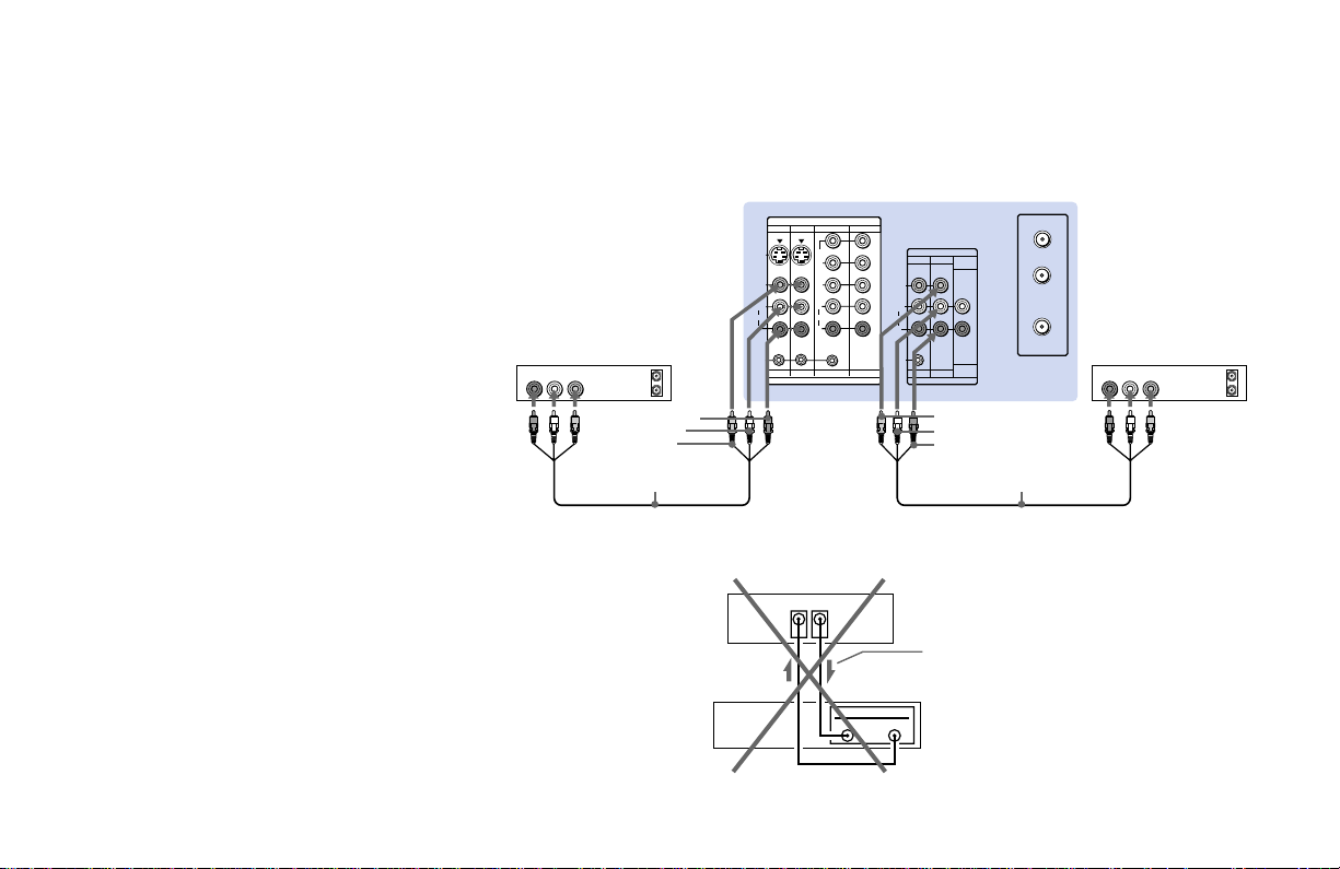
Connecting two VCRs for tape editing
By connecting a second VCR to MONITOR
OUT, you can record a program being played
by the primary VCR to the second VCR or
perform tape editing and dubbing.
1 Connect the VCR intended for playback
using the connection instructions on page
10 of this manual.
2 Using an AUDIO/VIDEO cable, connect
AUDIO and VIDEO IN on the VCR
intended for recording to AUDIO and
VIDEO OUT of MONITOR OUT on the
projection TV.
Notes:
• Do not change the input signal while
editing through MONITOR OUT.
• When connecting a single VCR to the
projection TV: if VCR LINE OUT is
connected to VIDEO IN on the projection
TV, do not connect MONITOR OUT on
the projection TV to the VCR LINE
INPUT (see right). Doing so will cause
program interference and other viewing
problems.
VCR (for playback)
AUDIO R AUDIO L VIDEO
1
OUT
LINE
IN
OUT
AUDIO-R
AUDIO-L
VIDEO
VMC-810S/820S
(not supplied)
Disconnect all power sources before making any connections.
(Rear of projection TV)
IN
VIDEO 1 VIDEO 3 VIDEO 4
S VIDEO
VIDEO
L
(MONO)
AUDIO
R
S-LINK
VIDEO 1 VIDEO 3 VIDEO 4 VIDEO 5
VIDEO 5
Y
B
P
PR
L
AUDIO
R
IN
(Rear of projectionTV)
VIDEO IN
MONITOR
OUT
VCR
IN
LINE
OUT
MONITOR
AUDIO
TV
(VAR/FIX)
VIDEO
L
(MONO)
AUDIO
R
S-LINK
MONITOR
TV
OUT
VIDEO
AUDIO-L
AUDIO-R
AUDIO
(VAR/FIX)
Indicates direction
of signal
OUT
AUX
TO
CONVERTER
VHF/UHF
VMC-810S/820S
(not supplied)
VCR (for recording)
AUDIO R AUDIO L VIDEO
OUT
LINE
IN
IN
2
15
Installing and Connecting the Projection TV (continued)
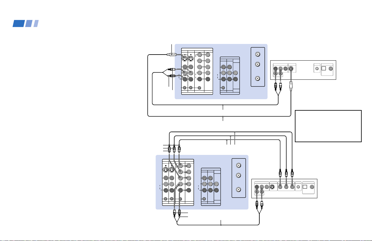
Connecting a DVD Player (Upper
illustration)
Using an AUDIO and S VIDEO cables,
connect AUDIO and S VIDEO IN on the
projection TV to AUDIO and S VIDEO OUT
on the DVD Player (White-AUDIO Left, RedAUDIO Right).
Connecting a DVD Player with
component video output
connectors (Lower illustration)
1 Using an AUDIO cable, connect AUDIO of
LINE OUT on the DVD Player to AUDIO of
VIDEO 4 or 5 IN on the projection TV
(White-AUDIO Left, Red-AUDIO Right).
2 Using three yellow VIDEO cables, connect
B, and PR of COMPONENT VIDEO
Y, P
OUT on the DVD Player to Y, P
VIDEO 4 or 5 IN on the projection TV.
Notes:
• Since the high quality pictures on a DVD
disc contain a lot of information, picture
noise may appear. In this case, adjust “Noise
Reduction” in the Video menu. (see “Noise
Reduction” on page 34)
• Some DVD Player terminals may be labeled
differently. If so, connect as follows:
Connect Y (green) to Y.
Connect P
Connect P
B (blue) to CB, Cb or B-Y.
R (red) to CR, Cr or R-Y.
B, and PR of
(Rear of
projection
TV)
S VIDEO
AUDIO-R
AUDIO-L
Y
PB
PR
VIDEO 1 VIDEO 3 VIDEO 4
S VIDEO
VIDEO
L
(MONO)
AUDIO
R
S-LINK
VIDEO 1 VIDEO 3 VIDEO 4 VIDEO 5
VIDEO 1 VIDEO 3 VIDEO 4
S VIDEO
VIDEO
L
(MONO)
AUDIO
R
S-LINK
VIDEO 1 VIDEO 3 VIDEO 4 VIDEO 5
IN
VIDEO 5
Y
P
B
P
R
L
AUDIO
R
IN
AUDIO-L
AUDIO-R
Disconnect all power sources before making any connections.
(Rear of projection TV)
IN
VIDEO 5
Y
B
P
PR
L
AUDIO
R
IN
OUT
MONITOR
AUDIO
TV
VIDEO
AUDIO
S-LINK
(VAR/FIX)
L
(MONO)
R
AUDIO
(VAR/FIX)
MONITOR
TV
OUT
RK-74A (not supplied)
YC-15V/30V (not supplied)
VMC-10HG (not supplied)
AUX
OUT
MONITOR
AUDIO
TV
(VAR/FIX)
VIDEO
L
(MONO)
AUDIO
R
S-LINK
AUDIO
(VAR/FIX)
MONITOR
TV
OUT
TO
CONVERTER
VHF/UHF
RK-74A (not supplied)
AUX
TO
CONVERTER
VHF/UHF
LINE OUT
R–AUDIO 1–L VIDEO
R–AUDIO 1–L VIDEO
S VIDEO OUT
LINE OUT
S VIDEO OUT
COMPONENT VIDEO OUT
DVD
S-LINK
DIGITAL OUT
OPTICAL COAXIAL
Audio/S video
outputs
Connect the DVD Player
directly to the projection TV.
Connecting the DVD Player
through other video
equipment will cause
unwanted picture noise.
DVD
S-LINK
DIGITAL OUT
OPTICAL COAXIAL
R-YY B-Y
16
 Loading...