

Sony KLV-40V550A Schematic
SERVICE MANUAL
EX2L
CHASSIS
MODEL COMMANDER DEST.
KLV-32V530A
KLV-32V550A
KLV-32V550A/R
(Red) Thailand, South Africa
KLV-32V550A/W
(White) Thailand, South Africa
KLV-40V530A
RM-GA015 ME
RM-GA015 India, ME, Philippines,
Russia, South Africa,
Thailand, Tunisia
RM-GA015 ME, Philippines,
RM-GA015 ME, Philippines,
RM-GA015 ME
MODEL COMMANDER DEST.
KLV-40V550A
KLV-40V550A/R
(Red) Thailand, South Africa
KLV-40V550A/W
(White) Thailand, South Africa
KLV-46V550A
KLV-52V550A
RM-GA015 India, Iran, ME,
Philippines, Russia,
South Africa,
Thailand, Tunisia
RM-GA015 ME, Philippines,
RM-GA015 ME, Philippines,
RM-GA015 India, ME, Philippines,
Russia, South Africa,
Thailand
RM-GA015 India, Iran. ME,
Philippines, Russia,
South Africa,
Thailand, Tunisia
KLV-32 V530A, V550A, V550A/R, V550A/W
KLV-46V550A
KLV-40 V530A, V550A, V550A/R, V550A/W
RM-GA015
KLV-52V550A
LCD COLOR TV

KLV-32, 40 V530A, 32, 40, 46, 52 V550A
RM-GA015
TABLE OF CONTENTS
Section Title Page
1. SAFETY NOTES
1-1. Caution Handling of LCD Panel ................................... 3
1-2. Safety Check Out ........................................................... 3
1-3. Leakage Test .................................................................. 3
1-4. WARNING ! .................................................................. 3
1-5. Lead Free Information ...................................................4
1-6. Attachment & Detachment of MDF61 Connector ........ 4
1-7. Attachment, Detachment & Confirmation of Lock
Condition of JST IBH Connector .................................. 4
1-8. Removal and Installation of Rear Cover Procedure ..... 6
1-9. Removal of Switch Unit Procedure............................... 7
2. SELF DIAGNOSTIC FUNCTION
2-1. Overview of Control Buttons ........................................ 8
2-2. LED Display Specification ............................................ 8
2-3. LED Display Control ..................................................... 8
2-4. LED Pattern ................................................................... 8
2-5. Standby LED Error Display .......................................... 9
2-6. Triage Chart ................................................................. 10
3. TROUBLESHOOTING
3-1. Flow chart .................................................................... 11
3-2. Board Replacement Order ........................................... 13
Section Title Page
7. DIAGRAMS
7-1. Block Diagram ............................................................. 44
7-2. Connector Diagrams .................................................... 45
7-2-1. KLV-32 V530A, V550A, V550A/R,
V550A/W .......................................................... 45
7-2-2. KLV-40 V530A, V550A, V550A/R,
V550A/W, 46V550A ....................................... 45
7-2-3. KLV-52V550A .................................................. 46
7-3. Circuit Board Location ................................................ 47
7-3-1. KLV-32 V530A, V550A, V550A/R,
V550A/W .......................................................... 47
7-3-2. KLV-40 V530A, V550A, V550A/R,
V550A/W ......................................................... 47
7-3-3. KLV-46V550A .................................................. 48
7-3-4. KLV-52V550A .................................................. 48
7-4. Schematic Diagram...................................................... 49
7-5. Printed Wiring Boards ................................................. 49
7-6. Semiconductors ........................................................... 49
8. EXPLODED VIEWS
8-1. KLV-32 V530A, V550A, V550A/R, V550A/W .......... 50
8-2. KLV-40 V530A, V550A, V550A/R, V550A/W .......... 52
8-3. KLV-46V550A ............................................................. 54
8-4. KLV-52V550A ............................................................. 56
4. DISASSEMBLY
4-1. KLV-32 V530A, V550A, V550A/R, V550A/W .......... 16
4-2. KLV-40 V530A, V550A, V550A/R, V550A/W .......... 17
4-3. KLV-46V550A ............................................................. 18
4-4. KLV-52V550A ............................................................. 20
5. WIRE DRESSING
5-1. KLV-32 V530A, V550A, V550A/R, V550A/W .......... 22
5-2. KLV-40 V530A, V550A, V550A/R, V550A/W .......... 27
5-3. KLV-46V550A ............................................................. 32
5-4. KLV-52V550A ............................................................. 37
6. SERVICE ADJUSTMENTS
6-1. Viewing Service Adjustment Data .............................. 43
6-2. Accessing Service Adjustment Mode ......................... 43
6-3. Accessing Diagnostic Menu ........................................ 43
9. ELECTRICAL PARTS LIST
9-1. KLV-32 V530A, V550A, V550A/R, V550A/W .......... 58
9-2. KLV-40 V530A, V550A, V550A/R, V550A/W .......... 59
9-3. KLV-46V550A ............................................................. 60
9-4. KLV-52V550A ............................................................. 61
OPERATING INSTRUCTIONS
– 2 –
SECTION 1
SAFETY NOTES
KLV-32, 40 V530A, 32, 40, 46, 52 V550A
RM-GA015
1-1. Caution Handling of LCD Panel
When installing the LCD Panel, make sure you are grounded
with a wrist band.
When installing the LCD Panel on the wall, the panel must be
secured using the 4 mounting holes on the rear cover.
1) Do not press the panel or frame edge to avoid the risk of
electric shock.
2) Do not scratch or press on the panel with any sharp
objects.
3) Do not leave the module in high temperature or in areas of
high humidity for an extended period of time.
4) Do not expose the LCD panel to direct sunlight.
5) Avoid contact with water. It may cause short circuit within
the module.
6) Disconnect the AC Cord when replacing the backlight
(CCFL) or inverter circuit. (High voltage occurs at the inverter
circuit at 650Vrms)
7) Always clean the LCD panel with a soft cloth material.
8) Use care when handling the wires or connectors of the
inverter circuit. Damaging the wires may cause a short circuit.
9) Protect the panel from ESD to avoid damaging the electronic circuit (C-MOS).
1-2. Safety Check-Out
After correcting the original service problem, perform the
following safety checks before releasing the set to the
customer:-
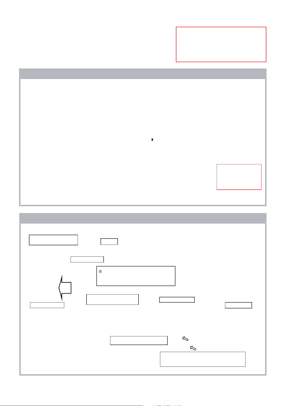
1-3. Leakage Test
The AC leakage from any exposed metal part to earth
ground and from all exposed metal parts to any exposed
metal part having a return to chassis must not exceed 0.5mA
(500 microamperes). Leakage current can be measured by
any one of the three methods:-
1. A commercial leakage tester such as the SIMPSON 229 or
RCA WT-540A. Follow the manufacturers instructions to use
those instructions.
2. A battery-operated AC milliampmeter. The DATA
PRECISION 245 digital multimeter is suitable for this job.
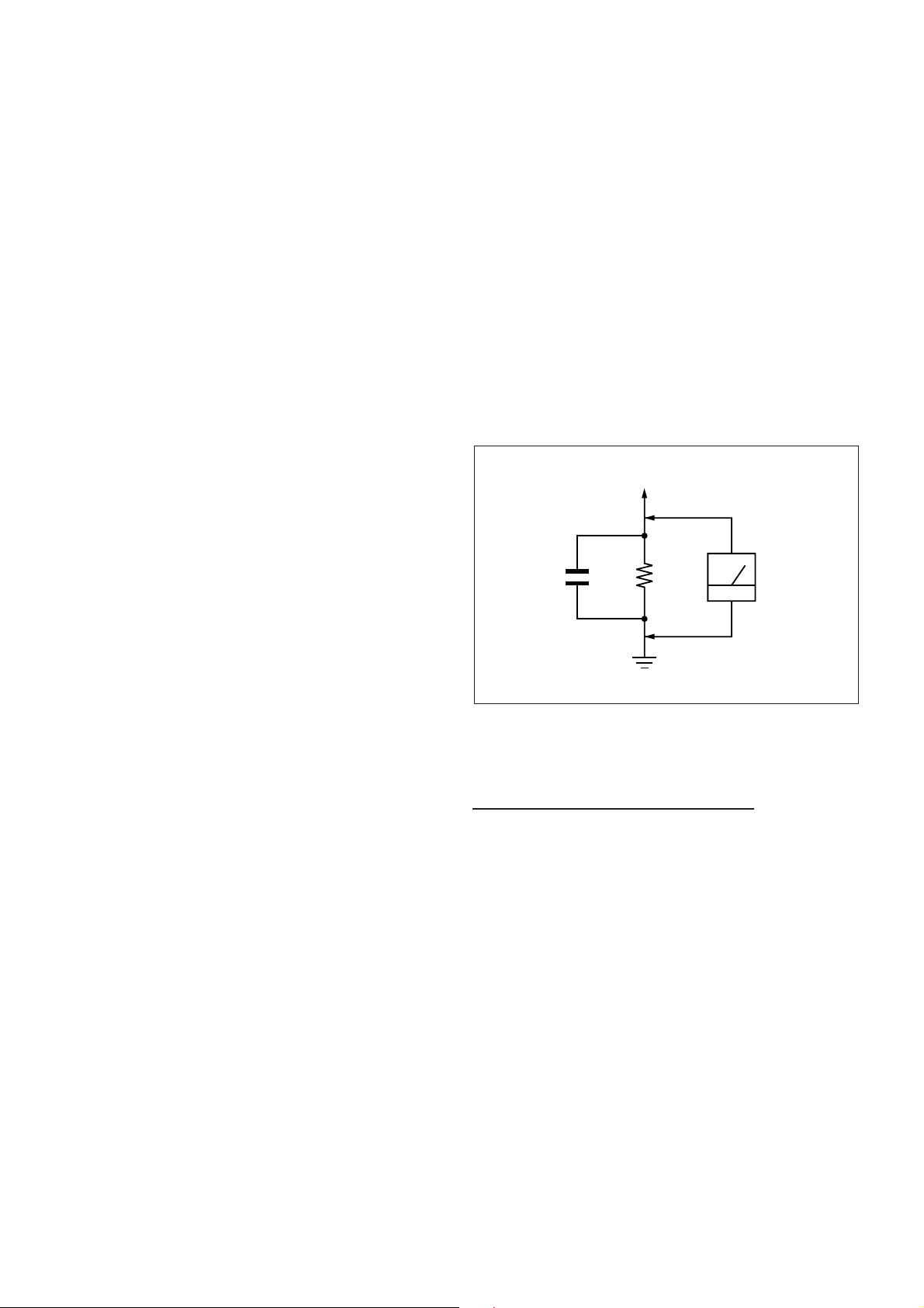
3. Measuring the voltage drop across a resistor by means of
a VOM or battery operated AC voltmeter. The 'limit' indication
is 0.75V so analog meters must have an accurate low voltage
scale. The SIMPSON'S 250 and SANWA SH-63TRD are
examples of passive VOMs that are suitable. Nearly all battery
operated digital multimeters that have a 2 VAC range are
suitable. (see Figure 1.)
To Exposed Metal
Parts on Set
0.15 µF
1.5 k
Ω
AC
Voltmeter
(0.75 V)
1) Check the area of your repair for unsoldered or poorly
soldered connections. Check the entire board surface for
solder splashes and bridges.
2) Check the interboard wiring to ensure that no wires are
"pinched" or contact high-wattage resistors.
3)Check all control knobs, shields, covers, ground straps and
mounting hardware have been replaced. Be absolutely certain
you have replaced all the insulators.
4) Look for unauthorized replacement parts, particularly
transistors that were installed during a previous repair. Point
them out to the customer and recommend their replacement.
5) Look for parts which, though functioning show obvious
signs of deterioration. Point them out to the customer and
recommend their replacement.
6) Check the line cords for cracks and abrasion.
Recommend the replacement of any such line cord to the
customer.
7) Check the antenna terminals, metal trim, "metallized"
knobs, screws and all other exposed metal parts for AC
leakage. Check leakage test as described next.
8) Live chassis can cause electric shock as its
connected to the AC power line. Therefore, use
isolation transformer and gloves when changing parts
or removing plug. Please remember high voltage is
there during servicing.
9) To follow safety after servicing, please make sure
the removed screws, parts and wires are as original
condition.
Earth Ground
Figure 1. AC voltmeter to check AC leakage
1-4. WARNING !
SAFETY-RELATED COMPONENT WARNING!
COMPONENTS IDENTIFIED BY SHADING AND MARK !
ON THE EXPLODED VIEWS ARE CRITICAL FOR SAFE
OPERATION. REPLACE THESE COMPONENTS WITH
SONY PARTS WHOSE PART NUMBERS APPEAR AS
SHOWN IN THIS MANUAL OR IN SUPPLEMENTS
PUBLISHED BY SONY. CIRCUIT ADJUSTMENTS THAT ARE
CRITICAL FOR SAFE OPERATION ARE IDENTIFIED IN
THIS MANUAL. FOLLOW THESE PROCEDURES
WHENEVER CRITICAL COMPONENTS ARE REPLACED
OR IMPROPER OPERATION IS SUSPECTED.
– 3 –
KLV-32, 40 V530A, 32, 40, 46, 52 V550A
RM-GA015
1-5. Lead Free Information
The circuit boards used in these models have been processed
using Lead Free Solder. The boards are identified by the LF
logo located close to the board designation.
Figure 2: LF logo
Figure 3: LF logo on circuit board
The servicing of these boards requires special precautions. It
is strongly recommended to use Lead Free Solder material in
order to guarantee optimal quality of new solder joints. Lead
Free Solder is available under the following part numbers:-
rebmuntraP retemaiD skrameR
7
91-500-046-mm
02-500-046-7m4.0Kg05.0
12-500-046-7m5.0Kg05.0
22-500-046-7m6.0Kg52.0
32-500-046-7m8.0Kg00.1
42-500-046-7m0.1Kg00.1
52-500-046-7m2.1Kg00.1
62-500-046-7m6.1Kg00.1
3.0Kg52.0
m
m
m
m
m
m
m
b) Detachment
(1)
Slide the slider to release
the slider lock.
(2) Press the center lock tab
to release the lock and pull
the connector up.
Unlock
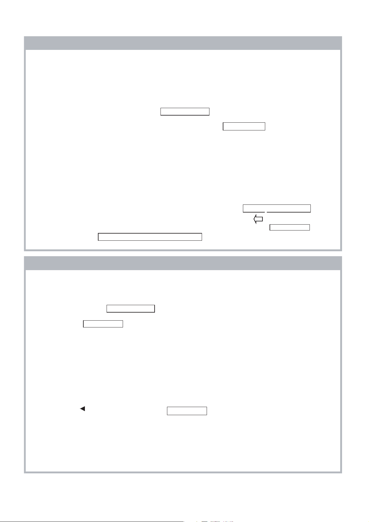
1-7. Attachment, Detachment & Confirmation of Lock
Condition of JST IBH Connector
(If applicable for these models)
Attention: This is a SAFETY CRITICAL PROCESS.
a) Attachment
(1) Press the center of the connector to insert it.
Due to high melting point of Lead Free Solder, the soldering
iron tip temperature needs to be set to 370 degrees
centigrade. This requires soldering equipment capable of
accurate temperature control coupled with a good heat
recovery characteristics.
For more information on the use of Lead Free Solder,
please refer to
http://www.sony-training.com
1-6. Attachment & Detachment of MDF61 Connector
(If applicable for these models)
a) Insertion
(1) Hold the center of a
connector.
(2) Press the center of the
connector to insert it.
Lock
(3) Slide the slider to lock the
connector.
(2) Press position
(NG for red marking portion)
(3) Prohibited matter (Refer Figure A~C explanation)
Figure A
Figure B
– 4 –
Figure C
Figure A: Do not press lock
portion.
Figure B: Do not press the
front side of the
connector.
Figure C: Do not press the side
of the connector.
KLV-32, 40 V530A, 32, 40, 46, 52 V550A
RM-GA015
b) Detachment
(1) Hold between the lock part and harness of socket.
Release the lock and pull out connector within 20
degree.
(2) Prohibited matter (Refer Figure D & E explanation)
Figure D
c) Confirmation of Lock Condition
(1) Confirm the lock conditions. When lock is completed,
base and socket must be same line as shown in Figure
F and G.
Figure F
Figure G
Figure E
Figure D: Do not pull out by holding the harness only.
Figure E: Do not pull out the connector when it does not
release the lock.
(2) NG Condition
It is NG condition when there are some gap between
base and socket such as in Figure H and I.
Gap
Figure H
Gap
– 5 –
Figure I
KLV-32, 40 V530A, 32, 40, 46, 52 V550A
RM-GA015
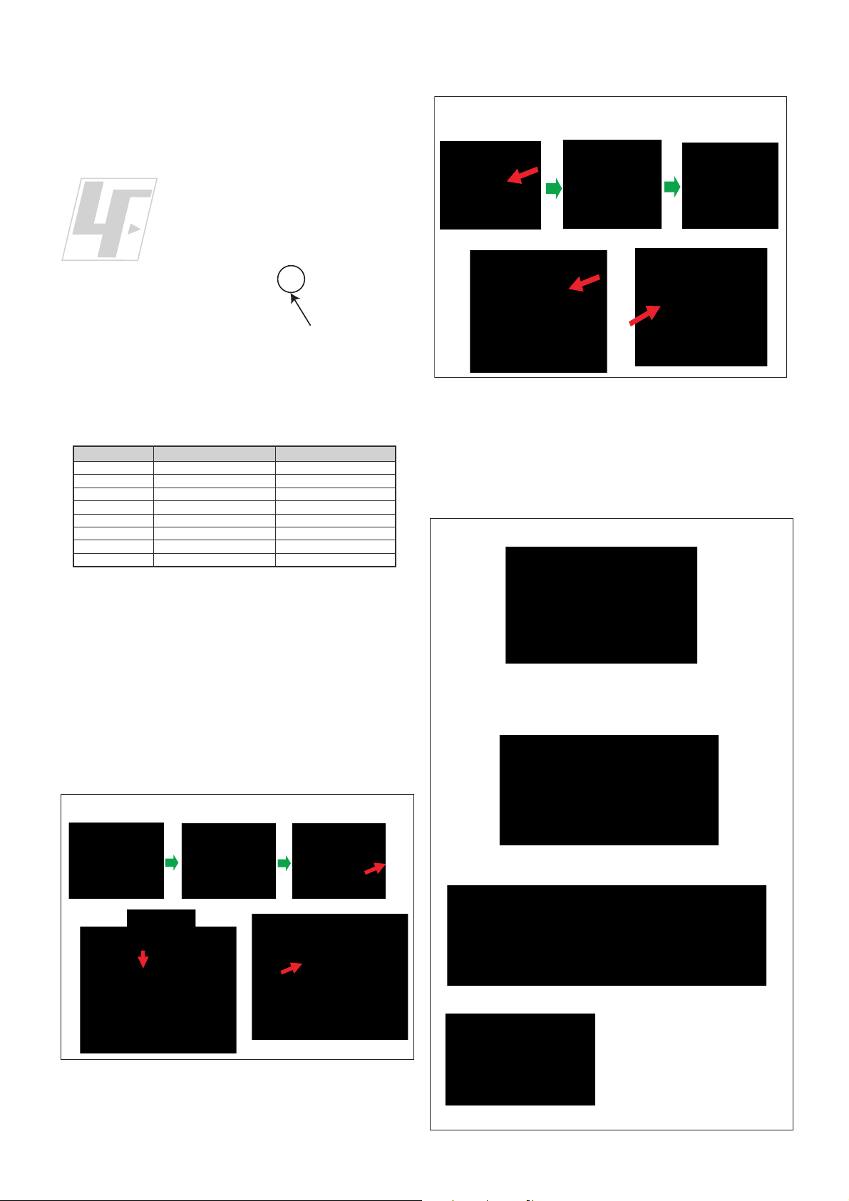
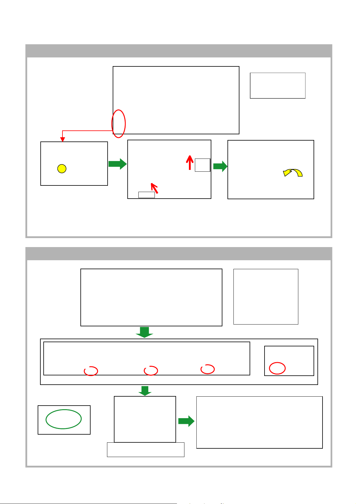
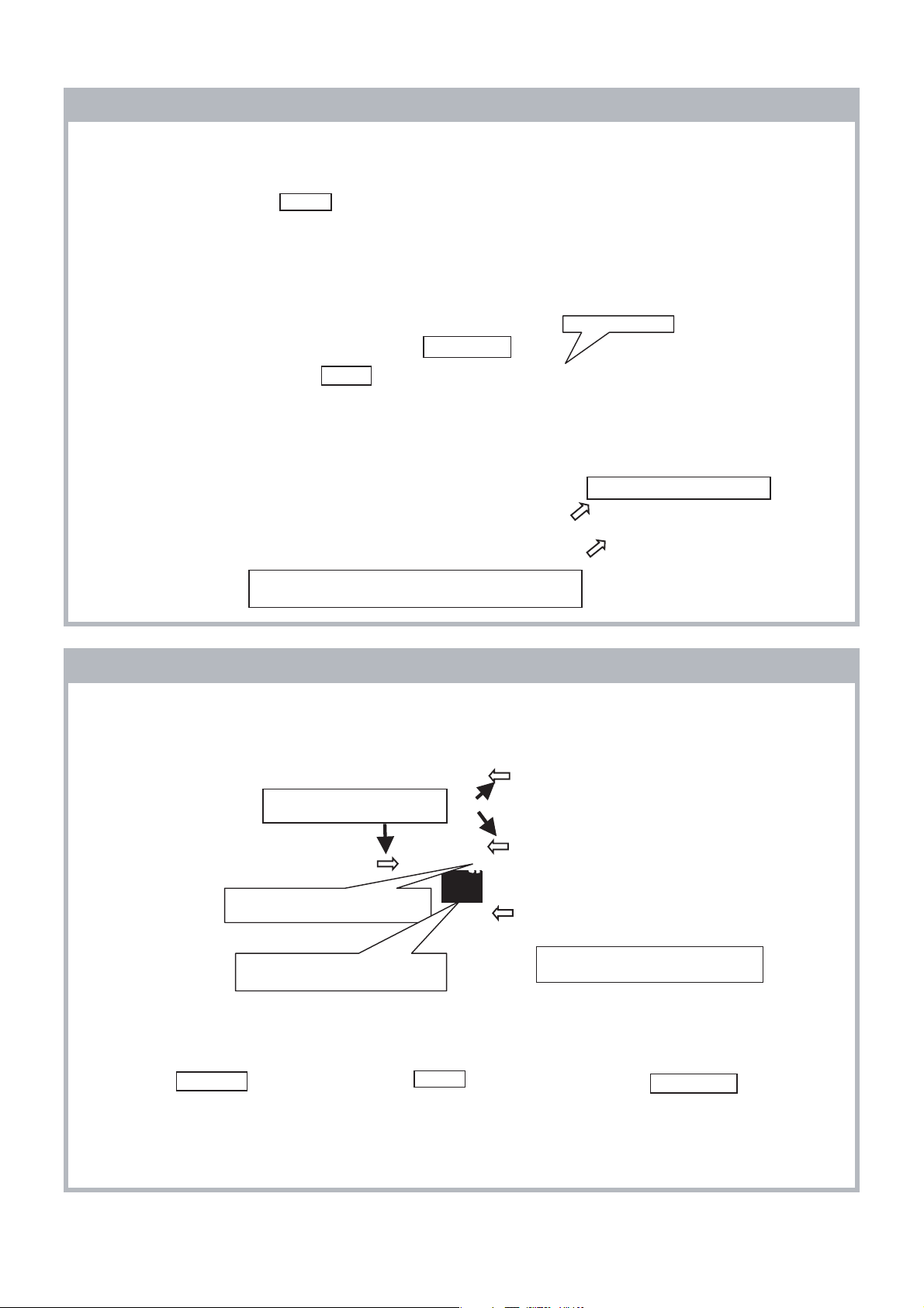
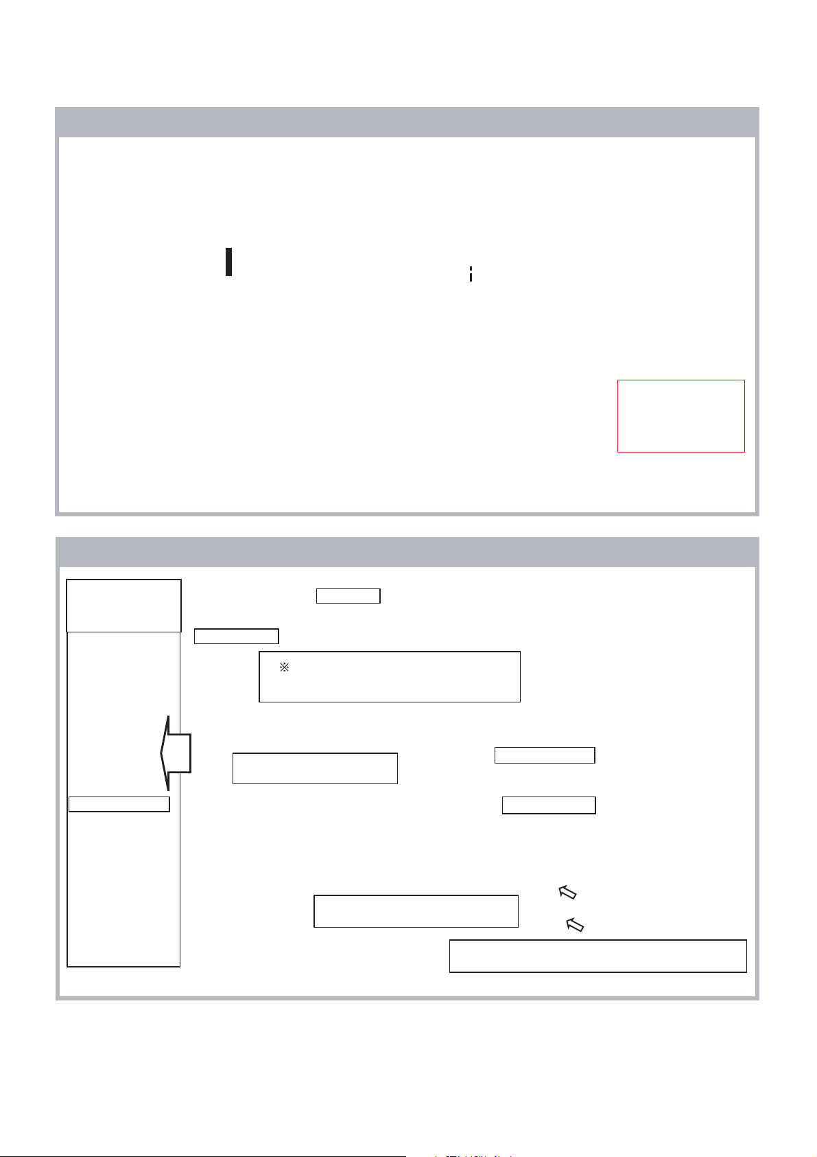
1-8. REMOVAL AND INSTALLATION OF REAR COVER PROCEDURE
a) REMOVAL
Note:
Please refer to
Section 4 : Disassembly
for screws informations .
PULL
UP
PUSH POINT
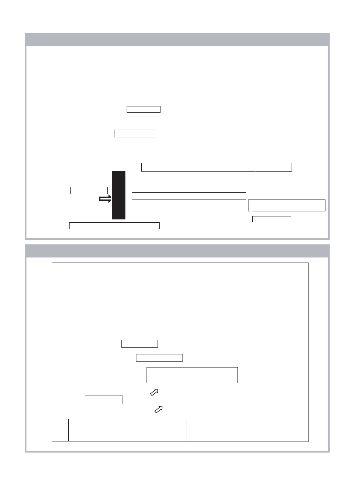
b) INSTALLATION
PUSH
a. PHOTO SHOW THE POSITION
DURING REAR COVER OPENING
b. PUSH TOWARDS INNER SET
WHILE REMOVE REAR COVER
FROM SIDE CONTROL
1
2
3
c. LIFT UP THE REAR
COVER FROM BOTTOM
Note:
1. Please refer to
Section 4 : Disassembly
for screws informations.
2. Please Make Sure Rear
Cover Not Overlap with
Bezel.
4
CLICK
<TOP SIDE>
CLICKING POSITION (PUSH
FROM REAR COVER TO BEZEL)
– 6 –
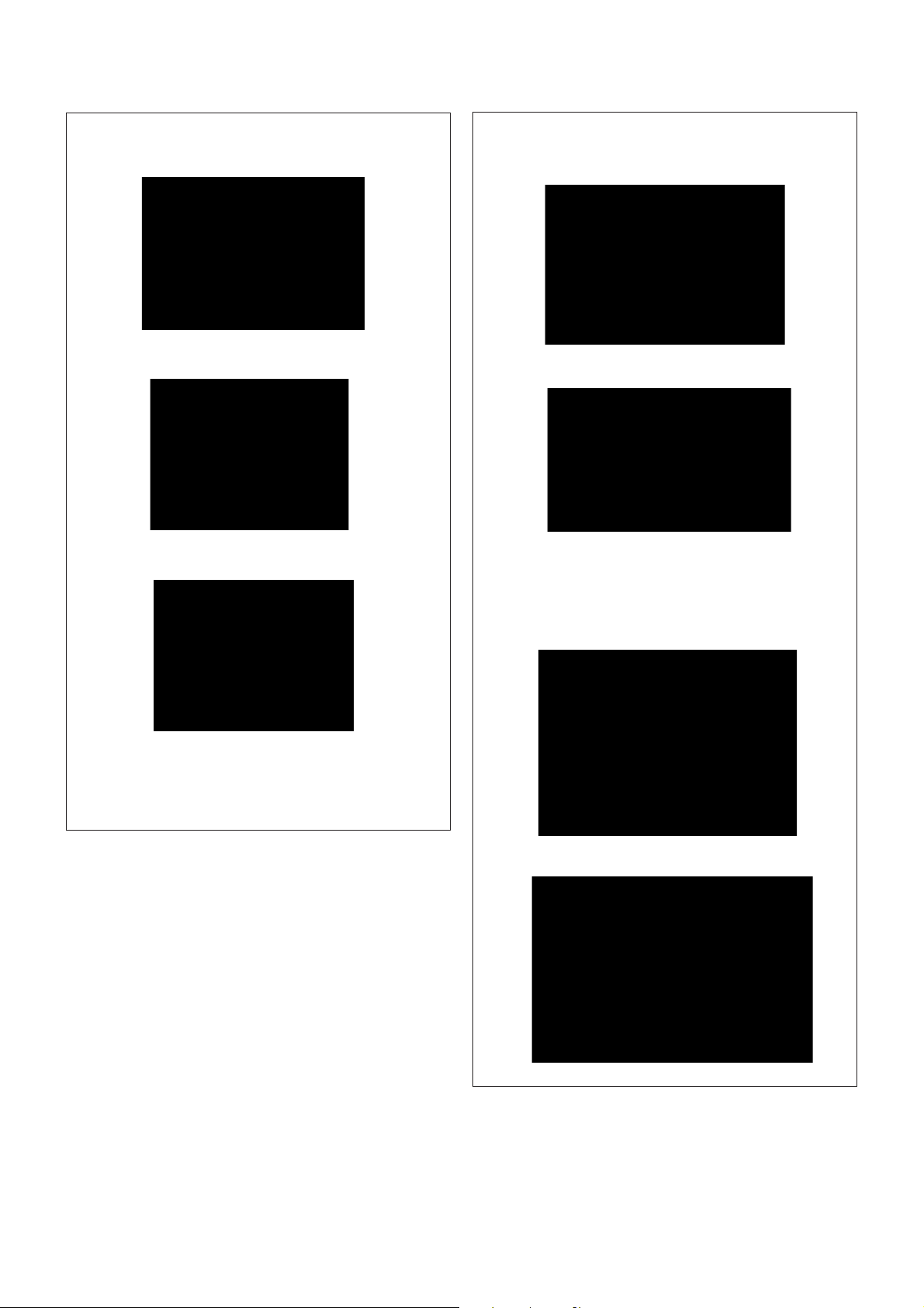
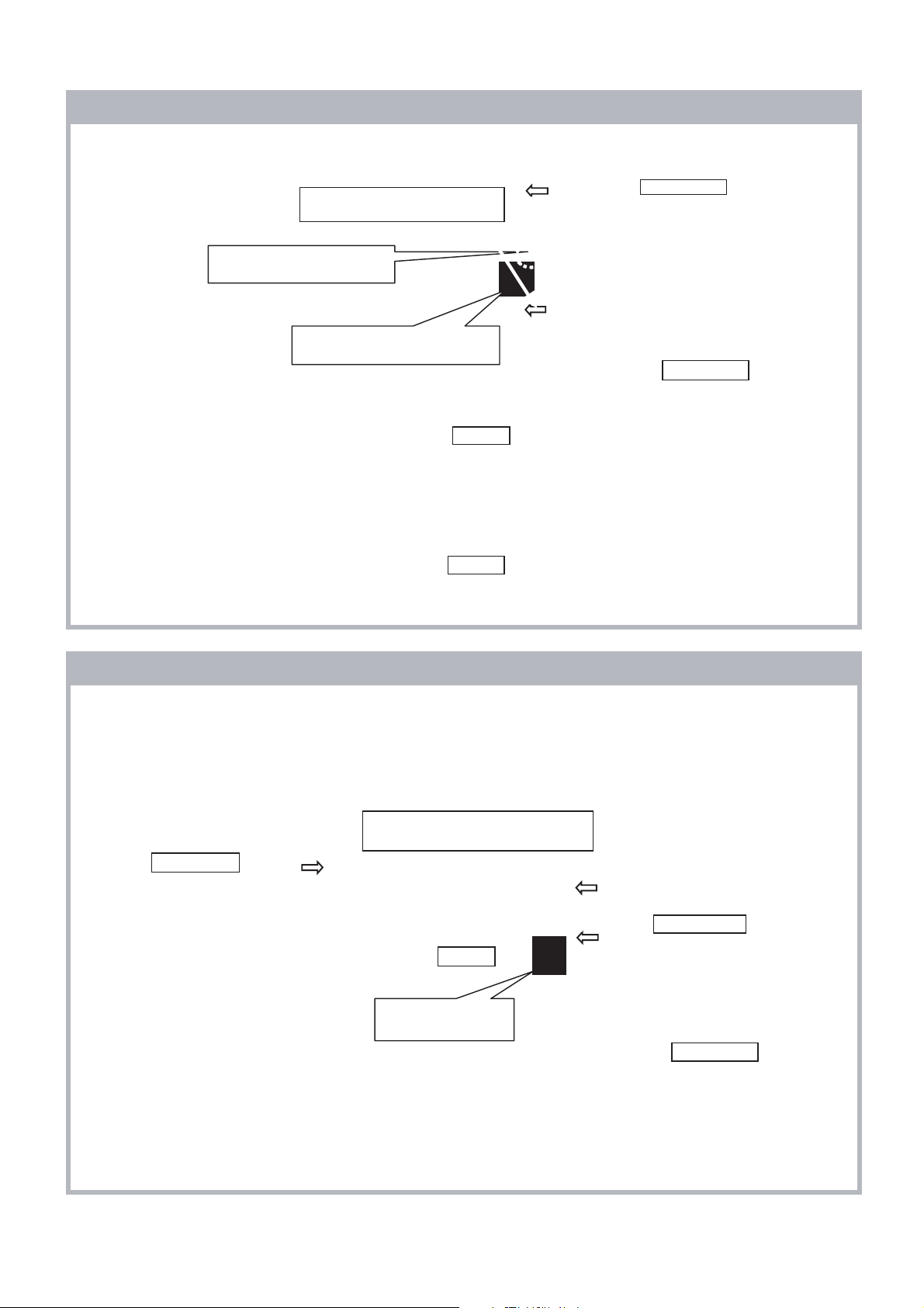
<RIGHT SIDE>
1. FOR EASIER INSTALLATION AT TOP SIDE, CLICK
THE REAR COVER FROM SIDE TO CENTER
2. PUSH THE REAR COVER AT 4 POSITIONS
UNTIL CLICK SOUND COME OUT.
3. 3 POSITIONS AT TOP SIDE AND 1 POSITION AT
RIGHT SIDE (NEAR SIDE CONTROL)
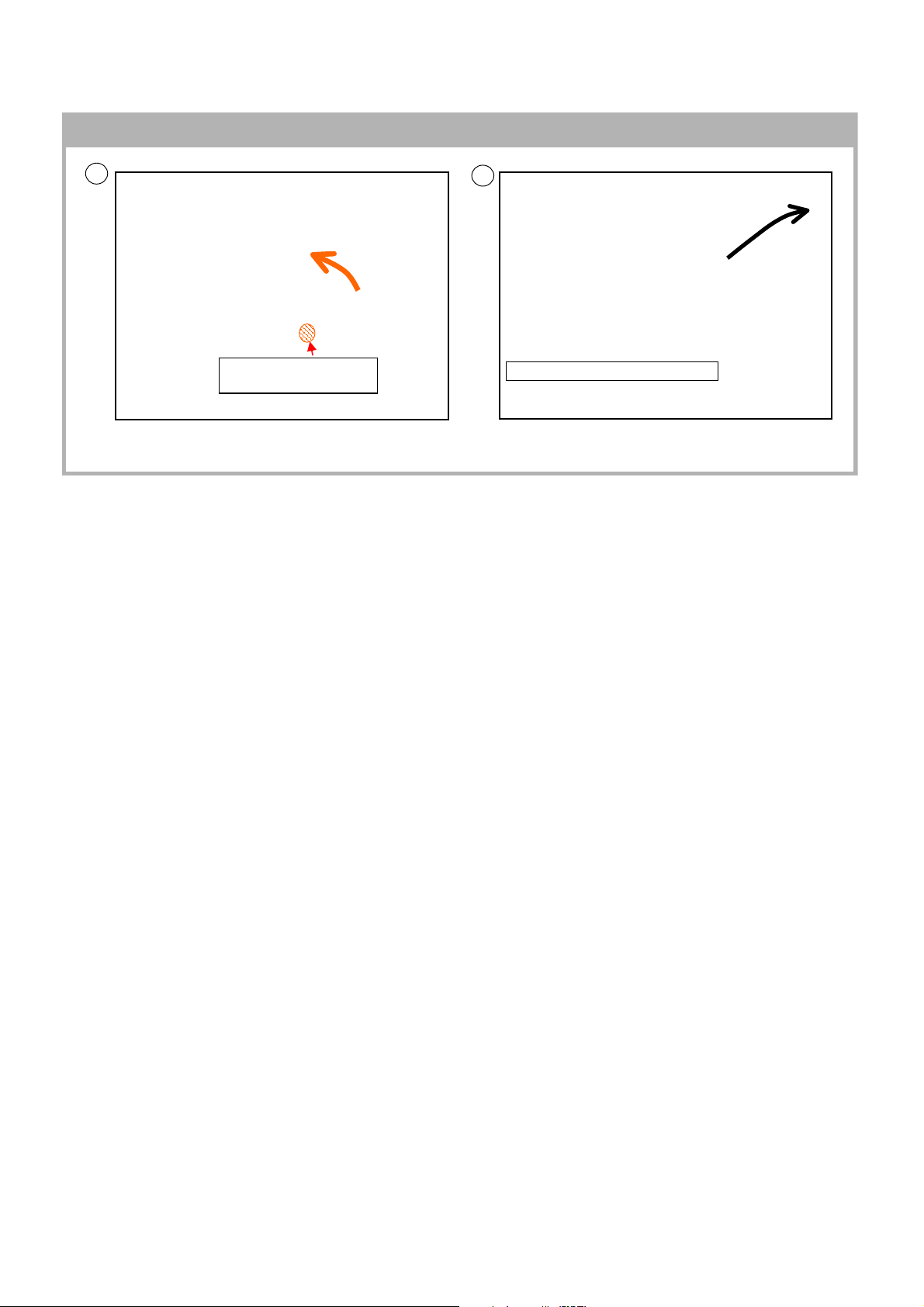
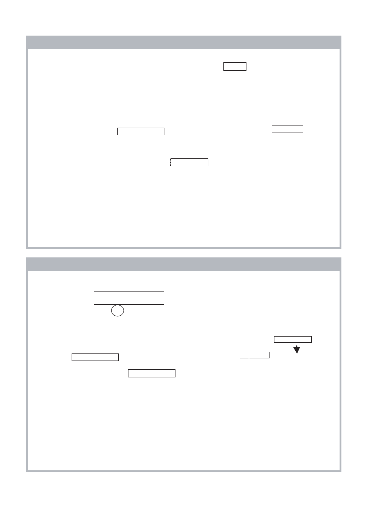
1-9. Removal of Switch Unit Procedure
a) REMOVAL
KLV-32, 40 V530A, 32, 40, 46, 52 V550A
RM-GA015
1
Push this position to remove
Switch Unit more easily
2
Push and slant towards inner side of set.
Push and slant towards inner side of set to remove Switch Unit correctly.
– 7 –
KLV-32, 40 V530A, 32, 40, 46, 52 V550A
RM-GA015
SECTION 2
SELF DIAGNOSTIC FUNCTION
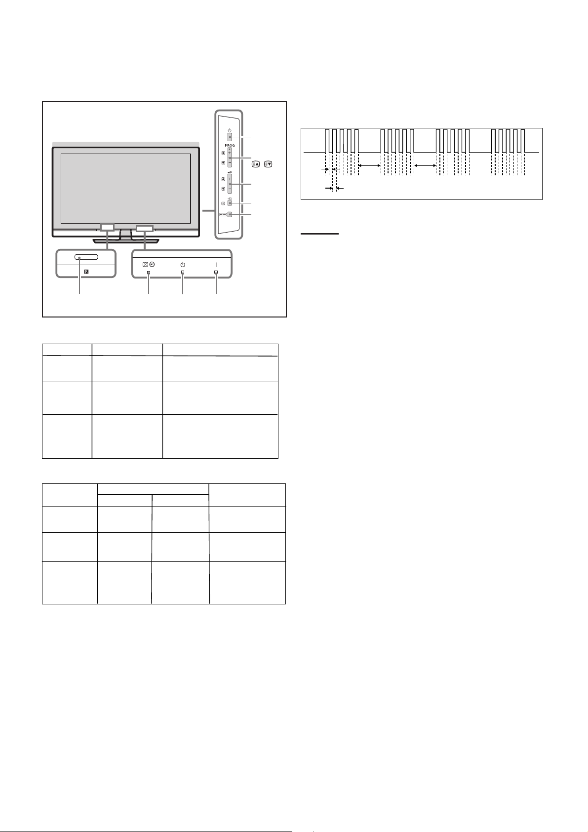
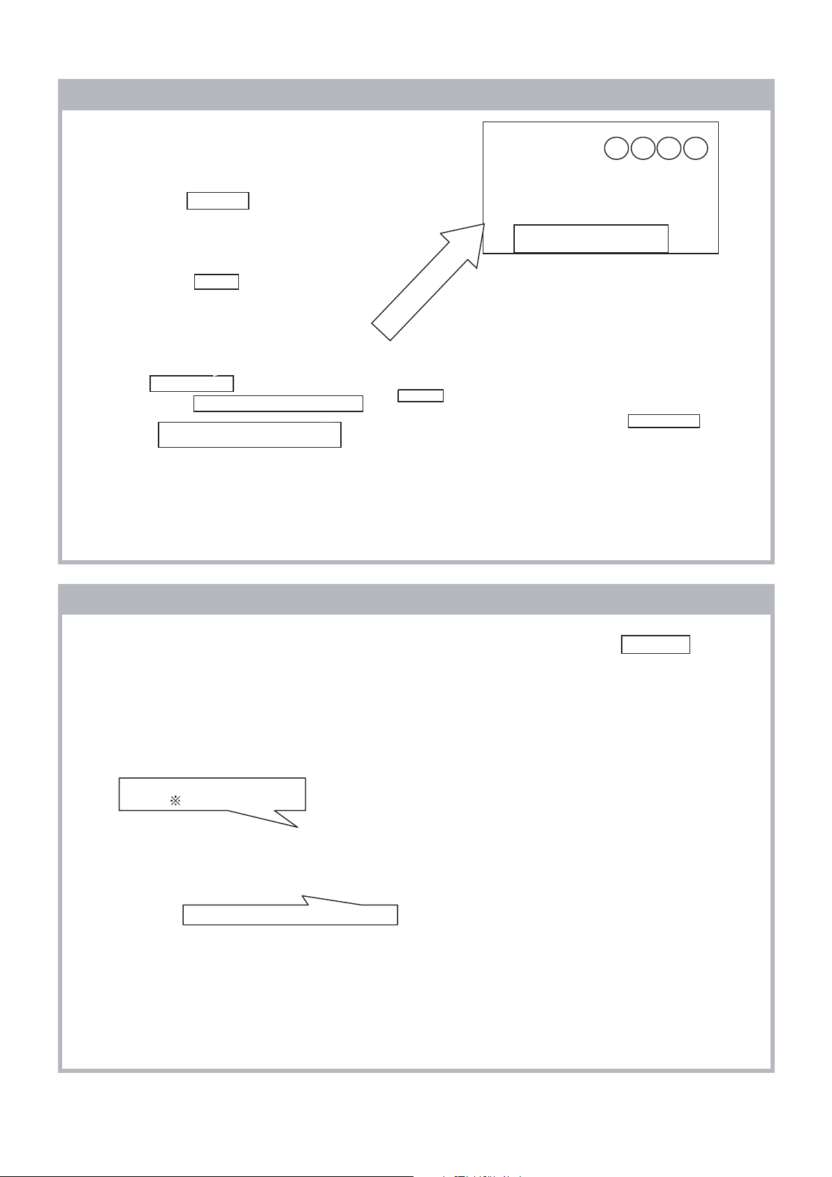
2-1. Overview of Control Buttons
Light sensor
Remote control sensor
Picture Off/Timer Standby Power
2-2. LED Display Specification
LED Typ e Description
POWER Green: LED
Green lights at power ON.
Remark
Power
PROG +/-/
/
Volume
Input select
Home
2-4. LED Pattern
When safety shutdown occurs, Standby LED display reports the
cause by using the lightning patterns as indicated below.
0.3 sec
2.0 sec
0.3 sec
2.0 sec
Example:
The figure above shows LED display when
SHUTDOWN is caused by DC_ALERT. It repeats
flashing for a specified number of times in 0.3sec/
cycle and has a 2 seconds interval of lighting off.
Please note that a 2 seconds interval of lighting off
is fixed regardless of abnormal state types.
STANDB
Picture Off/
Timer
Y Red: One LED Red lights during standby.
Green/Amber
: Two LEDs
Green lights during Picture
OFF and amber lights
during Timer activation.
2-3. LED Display Control
Status
Power LED
Display
Standby LED
POWER ON Green lights OFF
OF
STANDBY
Failure
FRed lights
OFF
Red flashes
Remark
Microcomputer is
in a normal state.
Microcomputer is
in a sleep state.
Classify the trouble
causes by the no.
of red blinking.
– 8 –
KLV-32, 40 V530A, 32, 40, 46, 52 V550A
2-5. Standby LED Error Display
Perform below countermeasures according to Standby LED blinking times.
Blinking times Error Countermeasure
2 DC_DET Replace either/all z Power board
- Power Unit(32" & 52")
- IP1 (40")
- IP2 (46")
z BA Board
5 DC_ALERT Replace BA board.
6BACKLIGHT Replace either/both z BA board
z Panel
7 INTERNAL TEMP Replace either/all z Power board
- Power Unit(32" & 52")
- IP1 (40")
- IP2 (46")
z BA board
RM-GA015
8AUDIO Replace either/all z Power board
z BA board
z Speaker
10 DIGITAL FE/DE Replace BA board.
13 BALANCER Replace either/all z Panel
z Power board
z D5N, D6N(52”)
14 T-CON Replace either/both z Panel
z BA board
Note: Each of the above blinking repeats 2 seconds.
- Power Unit(32" & 52")
- IP1 (40")
- IP2 (46")
- Power Unit(32" & 52")
- IP1 (40")
- IP2 (46")
– 9 –
KLV-32, 40 V530A, 32, 40, 46, 52 V550A
BA Board
HL1A Board
HSN Board
HSW Board
Power Unit (32")
Power Unit (52")
IP1 Board (40")
IP2 Board (46")
T-CON Board
Speaker Unit
RF Module
Panel Module
LVDS cable
Joint Connector
Flowchart
Problem
Doubtful Part
D5N Board (52")
A(i & ii) A(i & ii) A(i & ii) A(i & ii) A(i & ii) A(i & ii) A(i & ii)DDCCCCCBB
Few Possibility
Low B+ Low B+ Temp
Audio Balancer T-CON
Digital
BL
D6N Board (52")
Reference
Symptom-(Dead Set)
(Refer Section 3: Troubleshooting (for flow chart reference))
Video- Distorted or Missing
2
Blinks
5
Blinks
6
Blinks
7
Blinks
8
Blinks
10
Blinks
13
Blinks
14
Blinks
No
Power
No Video
BL OK
OSD OK
No Video
No BL
No Tuner
Video OK
No
HDMI
No
Audio
Tuner OK
Video 1-3
Bad
No Video
BL OK
No OSD
RM-GA015
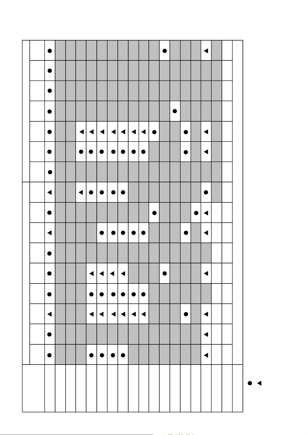
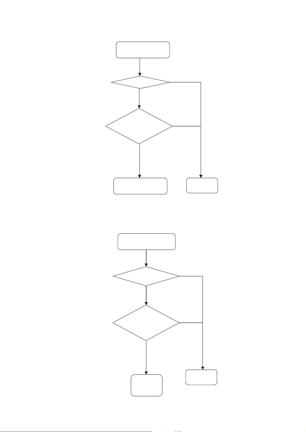
2-6. Triage Chart
– 10 –
2, 5, 7, 10, 13 blinks,
No Video/No BL, No Power
3.3V_DC
CN1300 3PIN on
BA Board
Does Power
Button work?
BA Board
Yes
Yes
Yes
AC Cable or AC Inlet
Power Unit or IP1 or
IP2 or D5N or D6N
(No STBY 3.3V)
Switch Unit
No
No
No
88-132VAC
Inlet on
Power Unit ,IP1, IP2,
D5N, D6N
176-264VAC
Inlet on
Power Unit,
IP1, IP2, D5N, D6N
Destination
Taiwan
E, Hong Kong
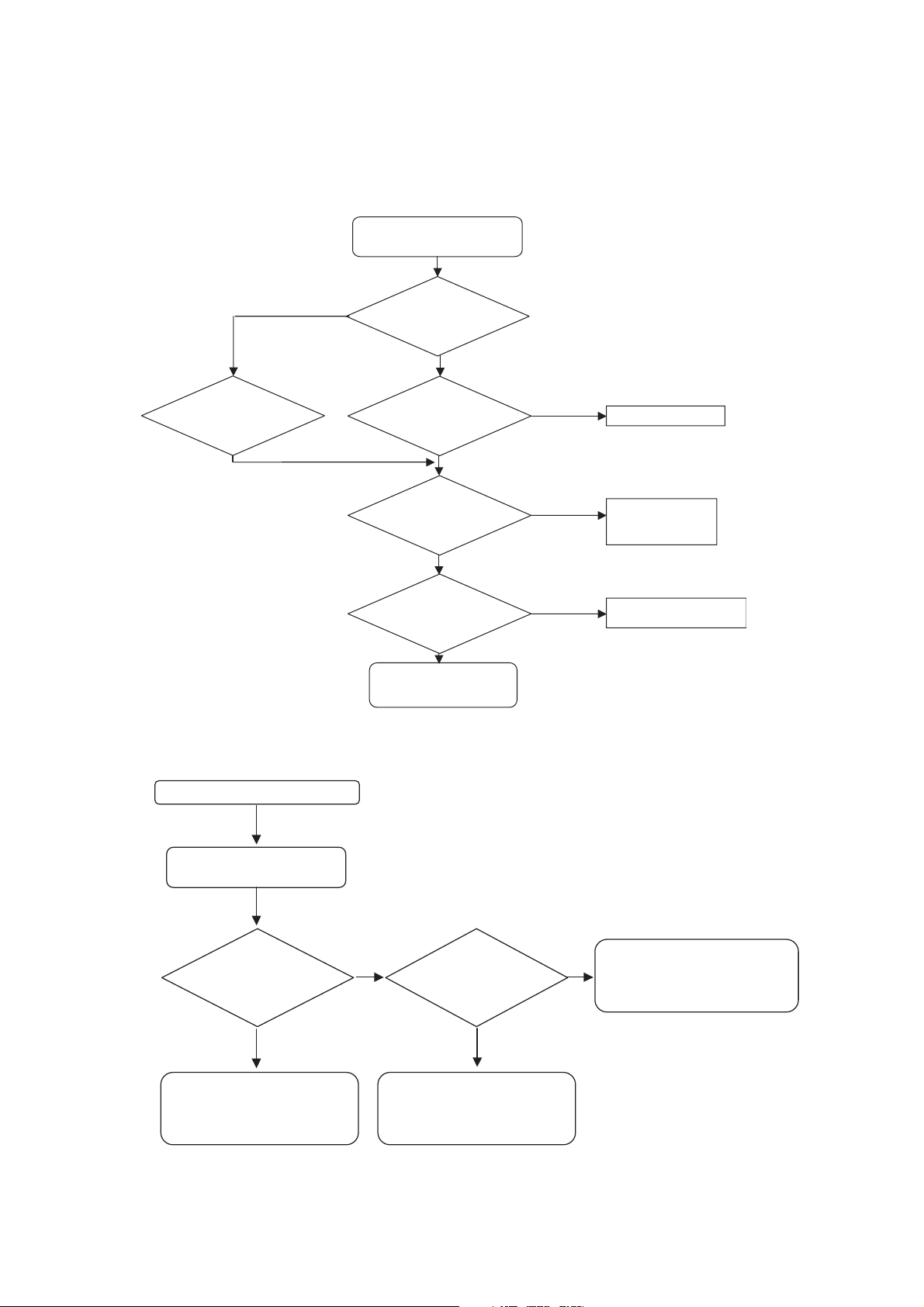
3.1 Flowchart
3-1-1. Flowchart A(i)
KLV-32, 40 V530A, 32, 40, 46, 52 V550A
RM-GA015
SECTION 3
TROUBLESHOOTING
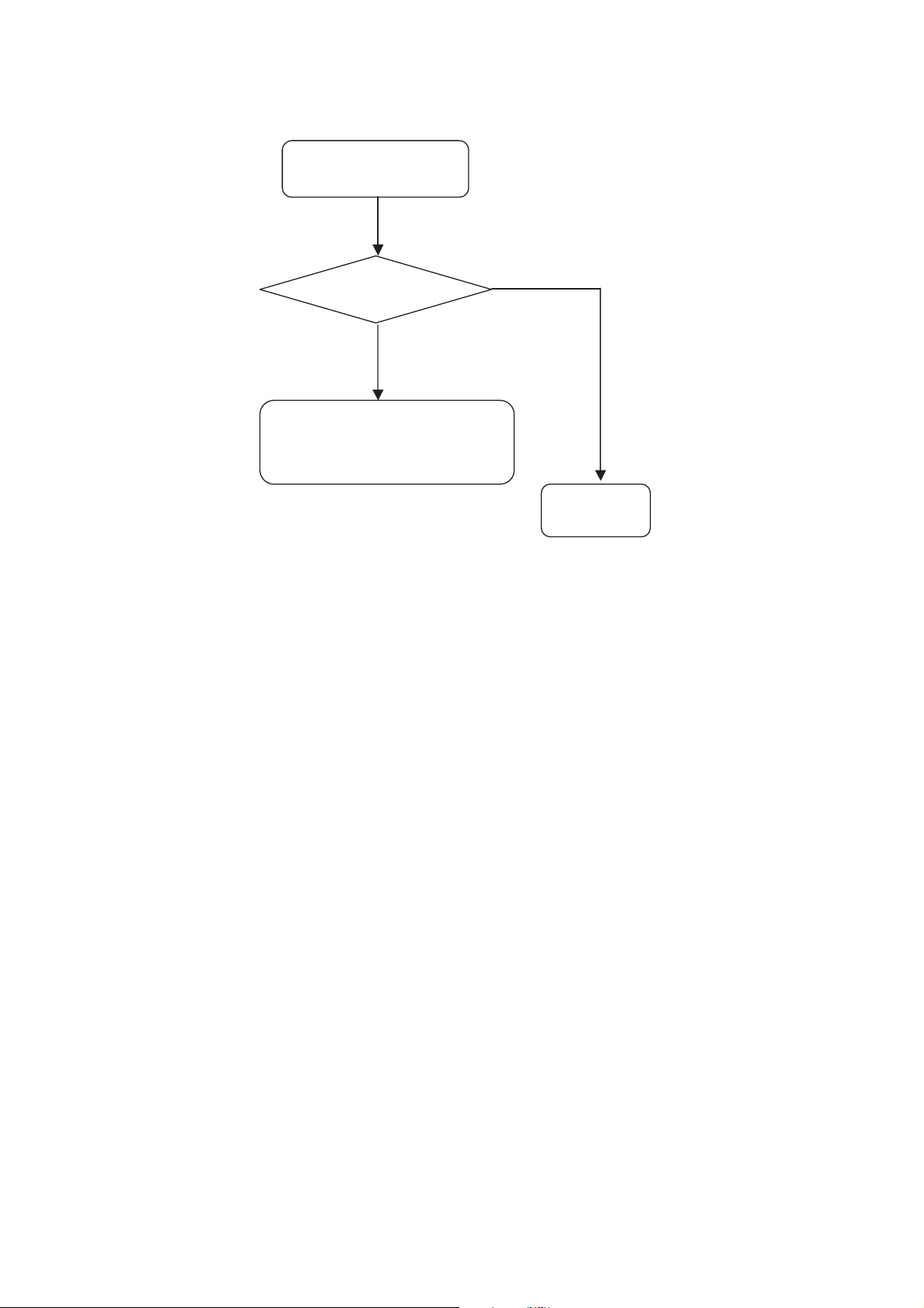
Flowchart A(ii)
No Power/Shut down/No Picture
Try On/Off at Main SW
and with Remote Commander
Is it LED(STBY)
indicator turn on
or blinked?
Yes
Count blink and replace board to
obey with 2-6 triage chart.
Refer Section 3.2 Board
Replacement Order.
No
Is it correct
Connection at
Wire harness?
Power source is out of order.
Other circuit block is out of order
except for Power board. Check
STBY3.3V Vcc line and circuit.
Yes
Check Harness holder, Header pin
No
and Wire harness.
Is it bended or damaged?
(If yes, replace it to a new one)
– 11 –
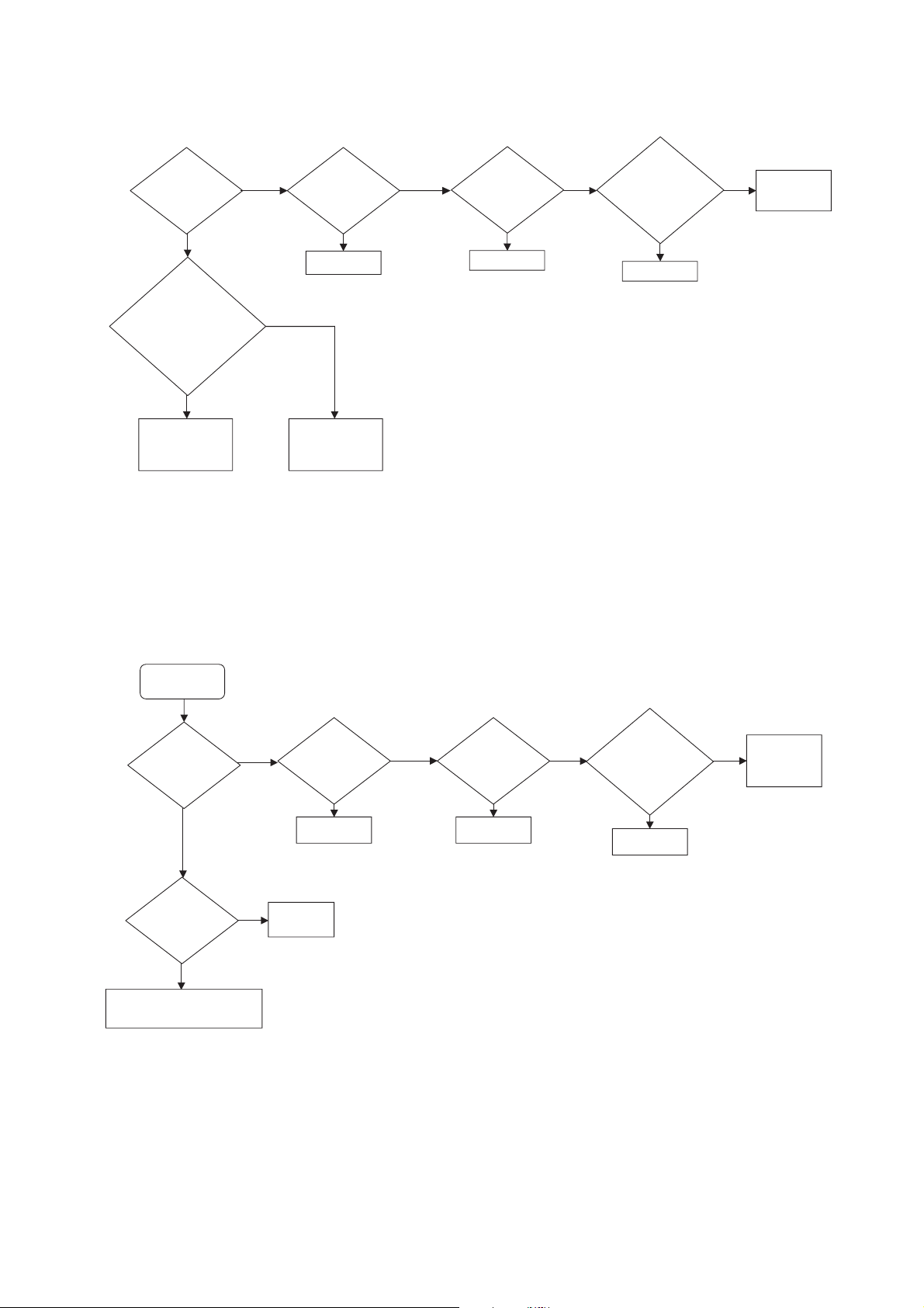
KLV-32, 40 V530A, 32, 40, 46, 52 V550A
Only
Speaker
out?
HDMI
Problem?
Digital
Channel
P
(Not used for
these models)
roblem?
BA Board
No No No No
UI of
Audio Setting
correct? Volume,
TV Speaker
BA Board
BA Board
Set correctly or
reset by menu
Check Speaker
BA board
No
Yes
Yes
BA Board
Analog
Channel
Problem?
BA Board
Video
Problem
All inputs
have
problem?
HDMI
Problem?
Analog
Channel
Problem?
No No No No
BA Board
BA Board
BA Board
Check LVDS h arness conn ection
Or BA board or Pane l
No
Yes
Yes
Backli ght
turn on?
BA Boar d
VIDEO PROBLEM
Digital
Channel
P
(Not used for
these models)
roblem?
RM-GA015
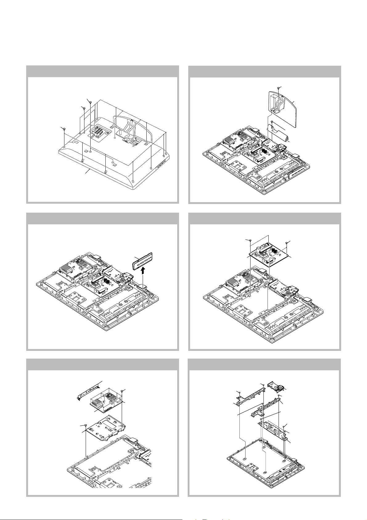
3-1-2. Flowchart B
3-1-3. Flowchart C
– 12 –
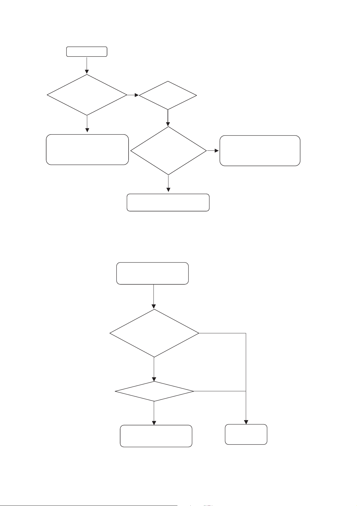
3-1-4. Flowchart D
NO
Power Unit or
IP1 or IP2 or
D5N or D6N
Replace (OK)
Finish
7 or 13 blinking
BA
Replace Panel
NO
Replace (OK)
Panel Problem
KLV-32, 40 V530A, 32, 40, 46, 52 V550A
RM-GA015
Is it LED(STBY)
indicator turn on
or blinked?
Yes
Count blink and replace board to
obey with 2-6 triage chart.
Refer Section 3.2 Board
Replacement Order.
No
Panel problem
Check T-Con and other parts
3.2 Board Replacement Order
3-2-1. In case of most doubtful part is Power Board
Backlight
turn on?
Yes
Is it correct
Connection at
LVDS Wire
Yes
Re-connect LVDS wire at T-Con
No
and at BA board.
Check conntacted pin!
Is it broken?
– 13 –
KLV-32, 40 V530A, 32, 40, 46, 52 V550A
Replace Panel
Finish
2 or 5 or 7 blinking
BA
NO
Replace (OK)
Replace (OK)
Power Unit or
IP1 or IP2 or D5N
or D6N
NO
BA Board
Finish
6 or 13 or 14 blinking
Panel
module
NO
Replace (OK)
Replace (OK)
Power Unit or
IP1 or IP2 or D5N
or D6N
NO
RM-GA015
3-2-2. In case of most doubtful part is BA Board
3-2-3. In case of most doubtful part is Panel module, T-con Board
– 14 –
Power Unit or IP1
or IP2 or D5N or D6N
Finish
10 blinking
BA board
Replace (OK)
NO
3-2-4. In case of most doubtful part is BA Board
KLV-32, 40 V530A, 32, 40, 46, 52 V550A
RM-GA015
– 15 –
KLV-32, 40 V530A, 32, 40, 46, 52 V550A
RM-GA015
Note:
1) The illustrations provided in this section might have slight difference from actual sets.
2) Refer to Removal & Installation of Rear Cover and Switch Unit Procedure in Section 1 Safety Notes.
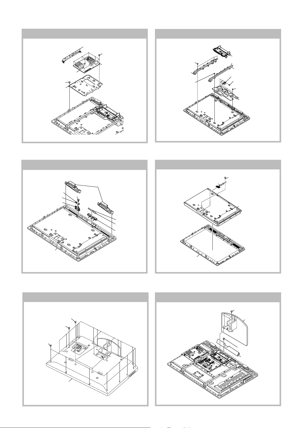
4-1. KLV-32 V530A, V550A, V550A/R, V550A/W
SECTION 4
DISASSEMBLY
4-1-1. Rear Cover Removal
3 Two screws
(+PSW M4 X 8)
2 Two screw
(+BVTP 3 X 12)
1 Fifteen screws
(+BVTP2 4 X 16)
4 Lift to remove
Rear Cover
4-1-3. Switch Unit Removal
3 Switch unit
Lift tabs to
2
remove board
4-1-2. Stand Assy Removal
4-1-4. Power Unit Removal
1 Two screws
(+BVST 3 X 8)
3 Remove connectors
1 Four screws
(+PSW 5 X 16)
2 Stand assy
3 One screw
(+BVTP2 4 X 16)
4 Bar Under (S)
2 Two screws
(+BVST 3 X 8)
4 Power Unit
4-1-5. BA Board Removal
2 Remove connectors
5 One screw
(+BVTP 3 X 12)
6 Frame, Main (32)
1 Bracket Side Jack
3 Nine screws
(+BVST 3 X 8)
4 BA board
1
4-1-6. Frame Removal
2 One screw
3 One screw
(+PSW M4 X 8)
4 Frame Spine (32L)
6 One screw
(+PSW M4 X 8)
(+PSW M4 X 8)
1 Cover, Under (S)
5 One screw
(+PSW M4 X 8)
7 Frame Spine (32R)
8 One screw
(+PSW M4 X 8)
9 Two screws
(+BVTP2 4 X 16)
q; One screw
(+PSW M4 X 8)
qa Frame Bottom (32)
– 16 –
KLV-32, 40 V530A, 32, 40, 46, 52 V550A
2 Stand assy
1 Four screws
(+PSW M5 X 16)
3 One screw
(+BVTP2 4 X 16)
4 Bar Under (S)
RM-GA015
4-1-7. Speaker, HSN and HL1A boards Removal
3 Remove connector
4 HSN board
5 Guide, IR (C)
9 Bezel Assy
2 One screw
(+BVTP 3 X 12)
1 Speaker (4.2 X 15.5cm)
6 Remove connector
7 HL1A board
8 Guide, LED (C)
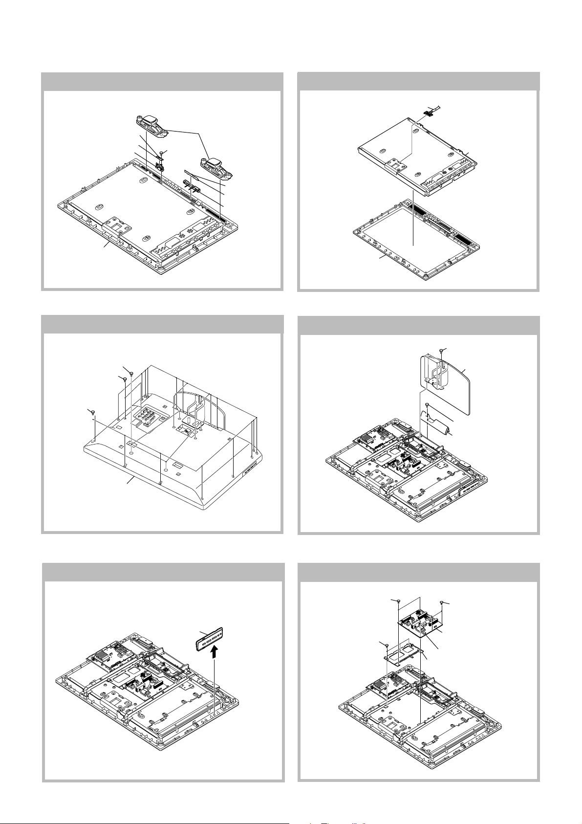
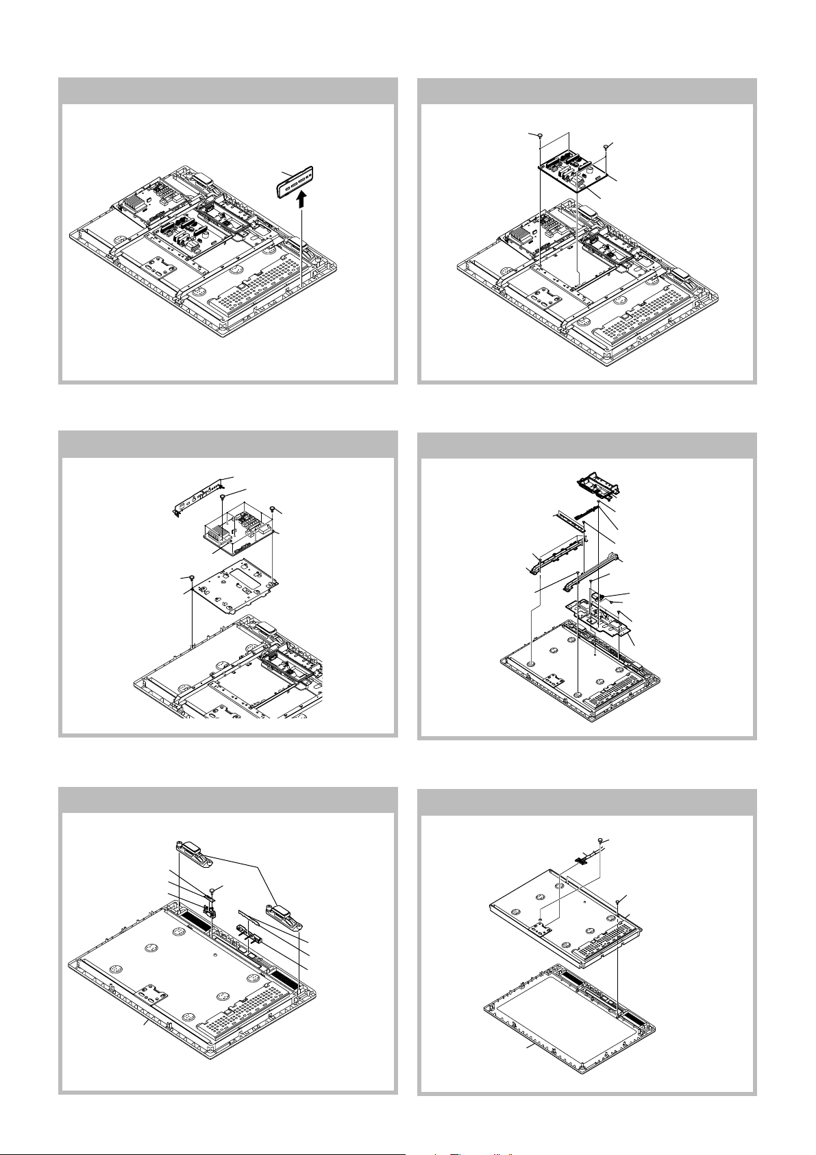
4-2. KLV-40 V530A, V550A, V550A/R, V550A/W
4-2-1. Rear Cover Removal
3 Four screws
(+PSW M4 X 12)
2 Two screw
(+BVTP 3 X 12)
4-1-8. Panel Removal
1 Harness
with connector
Bezel assy
4-2-2. Stand Assy Removal
2 LCD panel
1 Eighteen screws
(+BVTP2 4 X 16)
4 Lift to remove
Rear Cover
4-2-3. Switch Unit Removal
3 Switch unit
Lift tabs to
2
remove board
1
4-2-4. IP1 Board Removal
1 Two screws
5 Three screws
(+BVST 3 X 8)
2 Three screws
(+BVST 3 X 8)
4 IP1 Board
3 Remove connectors
6 Frame, IP1
– 17 –
KLV-32, 40 V530A, 32, 40, 46, 52 V550A
RM-GA015
4-2-5. BA Board Removal
1 Bracket Side Jack
3 Nine screws
(+BVST 3 X 8)
4 BA board
2 Remove connectors
5 One screw
(+BVTP 3 X 12)
6 Frame, Main (40)
4-2-7. Speaker, HSN and HL1A boards Removal
1 Loud Speaker
3 Remove connector
4 HSN board
5 Guide, IR (C)
2 One screw
(+BVTP 3 X 12)
4-2-6. Frame Removal
2 Three screws
(+PSW M4 X 8)
3 Frame Spine (40L)
4 Three screws
(+PSW M4 X 8)
4-2-8. Panel Removal
2 Harness
with connector
1 Cover, Under (M)
5 Frame Spine (40R)
7 AC Inlet
6 One screw
(+KTT 3 X 10 (S TYPE))
8 Three screws
(+BVTP2 4 X 16)
9 Frame Bottom (40)
1 One screw
(+PSW M3 X 5)
3 LCD panel
9 Bezel Assy
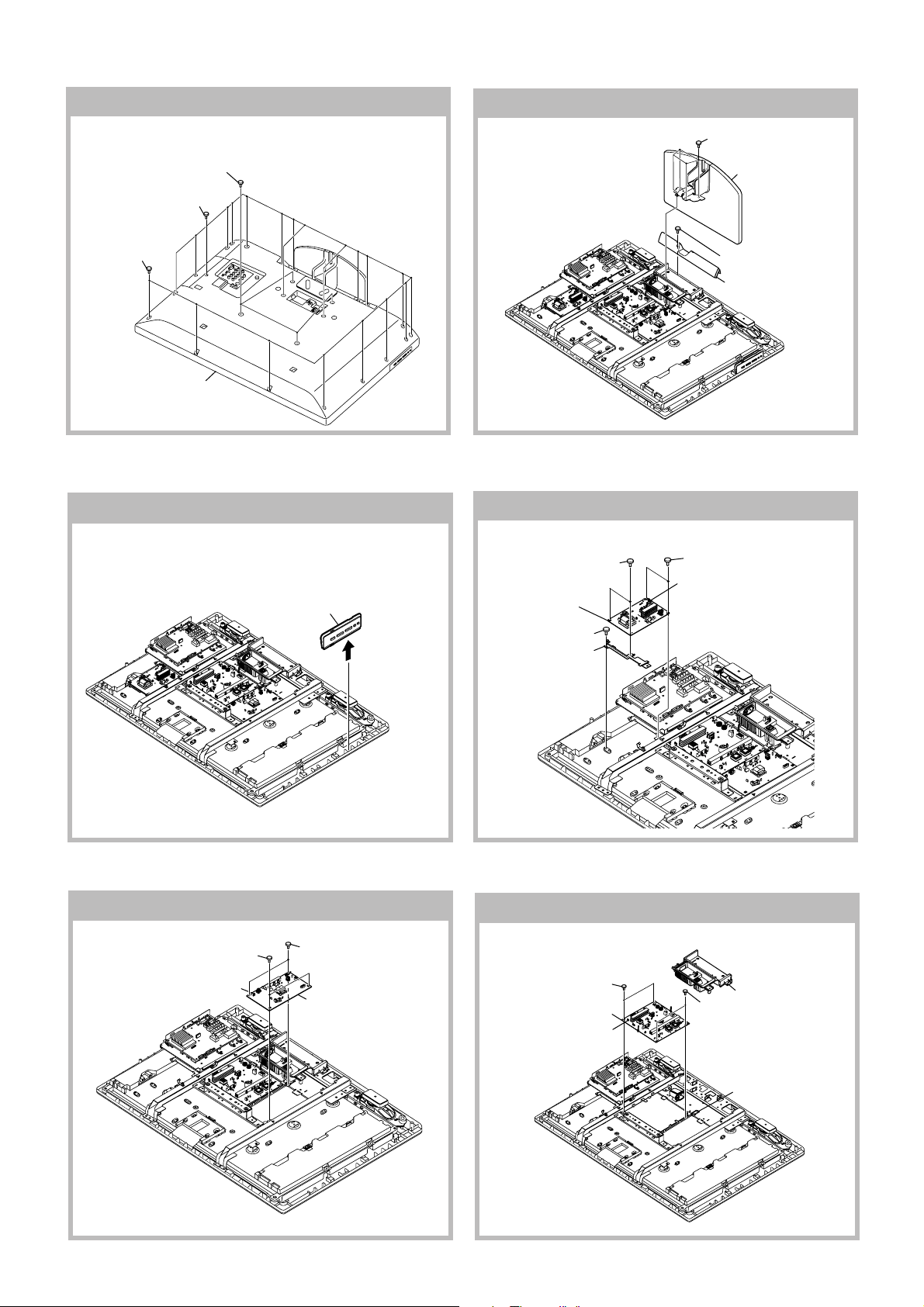
4-3. KLV-46V550A
4-3-1. Rear Cover Removal
3 Four screws
(+PSW M4 X 12)
2 Two screw
(+BVTP 3 X 12)
1 Twenty screws
(+BVTP2 4 X 16)
6 Remove connector
7 HL1A board
8 Guide, LED (C)
Bezel assy
4-3-2. Stand Assy Removal
1 Four screws
(+PSW M5 X 16)
2 Stand assy
3 One screw
(+BVTP2 4 X 16)
4 Bar Under (M)
4 Lift to remove
Rear Cover
– 18 –
KLV-32, 40 V530A, 32, 40, 46, 52 V550A
RM-GA015
4-3-3. Switch Unit Removal
4-3-5. BA Board Removal
1 Side Jack Bracket
4 Remove connectors
6 One screw
(+BVTP 3 X 12)
7 Frame, Main (46)
3 Switch unit
3 One screw
(+PSW M3 X 5)
2 Nine screws
(+BVST 3 X 8)
5 BA board
Lift tabs to
2
remove board
1
4-3-4. IP2 Board Removal
1 Two screws
(+BVST 3 X 8)
4-3-6. Frame Removal
5 Frame, Center
6 Four screws
(+PSW M5 X 8)
7 Frame Spine (46L)
8 Four screws
(+PSW M5 X 8)
2 Two screws
(+BVST 3 X 8)
3 IP2 board
4 Five connectors
1 Cover, Under(M)
2 One screw
(+BVST 3 X 8)
3 Frame, G
4 Two screws
(+PSW M5 X 8)
9 Frame Spine (46R)
qd One screw
(+PSW M5 X 8)
qa AC Inlet
q; One screw
(+KTT 3 X 10 (S TYPE))
qs Three screws
(+BVTP2 4 X 16)
qf Frame Bottom (46)
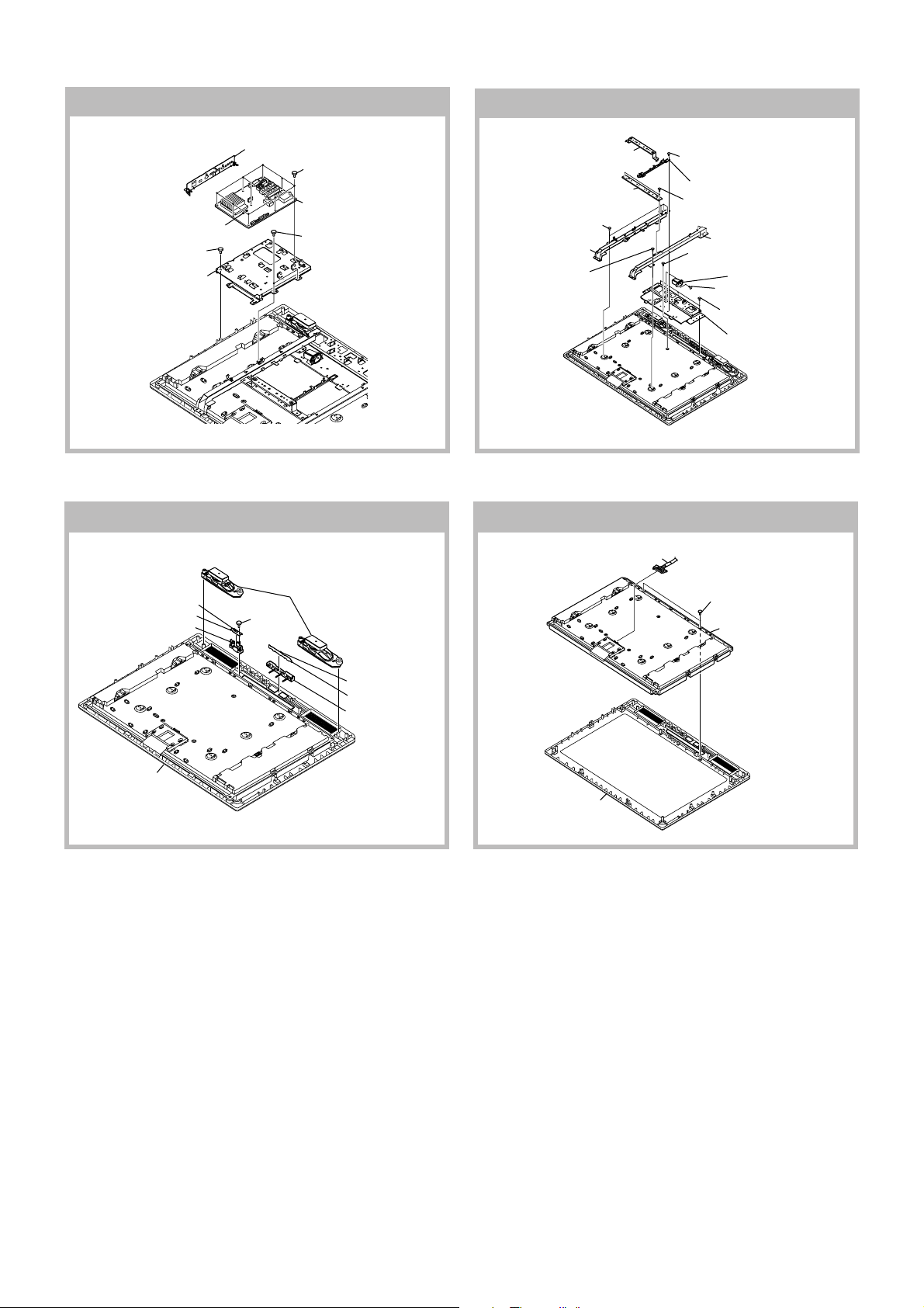
4-3-7. Speaker, HSN and HL1A boards Removal
3 Remove connector
4 HSN board
5 Guide, IR (C)
9 Bezel Assy
2 One screw
(+BVTP 3 X 12)
1 Loud Speaker
6 Remove connector
7 HL1A board
8 Guide, LED (C)
– 19 –
4-3-8. Panel Removal
1 Harness
with connector
Bezel assy
2 One screw
(+PSW M3 X 5)
3 Two screws
(+BVTP2 4 X 16)
4 LCD panel
KLV-32, 40 V530A, 32, 40, 46, 52 V550A
RM-GA015
4-4. KLV-52V550A
4-4-1. Rear Cover Removal
3 Four screws
(+PSW M4 X 12)
2 One screw
(+BVTP 3 X 12)
1 Twenty screws
(+BVTP2 4 X 16)
4 Lift to remove
Rear Cover
4-4-3. Switch Unit Removal
3 Switch unit
2
Lift tabs to
remove board
1
4-4-2. Stand Assy Removal
4-4-4. D6N Board Removal
1 Two screws
(+BVST 3 X 8)
4 D6N board
5 One screw
(+PSW M3 X 5)
6 Frame D6
1 Four screws
(+PSW M5 X 16)
2 Stand assy
3 One screw
(+BVTP2 4 X 16)
4 Bar Under
2 Two screws
(+BVST 3 X 8)
3 Remove connectors
4-4-5. D5N Board Removal
2 Two screws
(+BVST 3 X 8)
3 Remove connectors
1 Two screws
(+BVST 3 X 8)
4 D5N board
– 20 –
4-4-6. Power Unit Board Removal
3 Two screws
(+BVST 3 X 8)
5 Power Unit
4 Remove connectors
2 Two screws
(+BVST 3 X 8)
1 Cover, Under (L)
Frame G
KLV-32, 40 V530A, 32, 40, 46, 52 V550A
RM-GA015
4-4-7. BA Board Removal
1 Bracket Side Jack
2 Nine screws
(+BVST 3 X 8)
4 BA board
3 Remove connectors
5 One screw
(+BVTP 3 X 12)
7 Frame, Main (52)
6 Two screws
(+PSW M3 X 5)
4-4-9. Speaker, HSN and HL1A boards Removal
4-4-8. Frame Removal
1 Frame Vesa Top (52)
5 Frame, Center
6 Four screws
(+PSW M5 X 8)
7 Frame Spine (52L)
8 Four screws
(+PSW M5 X 8)
4-4-10. Panel Removal
1 Harness
with connector
2 One screw
(+BVST 3 X 8)
3 Frame, G
4 Two screws
(+PSW M5 X 8)
9 Frame Spine (52R)
qd One screw
(+PSW M5 X 8)
qa AC Inlet
q; One screw
(+KTT 3 X 10 (S TYPE))
qs Three screws
(+BVTP2 4 X 16)
qf Frame Bottom (52)
3 Remove connector
4 HSN board
5 Guide, IR (C)
9 Bezel Assy
2 One screw
(+BVTP 3 X 12)
1 Loud Speaker
6 Remove connector
7 HL1A board
8 Guide, LED (C)
Bezel assy
2 Two screws
(+BVTP2 4 X 16)
3 LCD panel
– 21 –
KLV-32, 40 V530A, 32, 40, 46, 52 V550A
RM-GA015
SECTION 5
WIRE DRESSING
5-1. KLV-32 V530A, V550A, V550A/R, V550A/W
5-1-1. Wire Dressing Overview
P.8 P.9
P.7
P.2
P.10
P.3
CAUTION :
1. Do not overpull the wires during dressing
--> avoid disconnection of wires.
2. Make sure wires are kept away from
sharp edges, heatsinks & other
high-temperature parts.
P.6
P.4 P.5
Note:
For details of each
area dressing, refer
to area information
5-1-2. P.2 Area
Please fix the harness at a
position of UL TAPE
SHEET(CORE)C
Inverter
HSW3 Board
About the harness processing to H1SW Board
Make sure wires are always at the side of the
Make sure wires are not close to
panel edge.
Pull speaker wire away from speaker
panel and are not loose.
SHEET(CORE)C
1-910-053-97
screw boss.
Make sure speaker wire away from screw boss. To
prevent sandwiched by Rear Cover during installation.
– 22 –
5-1-3. P.3 Area
KLV-32, 40 V530A, 32, 40, 46, 52 V550A
RM-GA015
SHEET(CORE)C
1-910-053-97
Make sure wire and Sheet Core(C) are not at clear panel area.
5-1-4. P.4 Area
Pull wire to this direction.
HL1A Board
Process the harness through the slit.
SHEET(CORE)C
1-910-053-97
HSN Board
– 23 –
KLV-32, 40 V530A, 32, 40, 46, 52 V550A
RM-GA015
5-1-5. P.5 Area
CLAMP
SHEET(CORE)C
1-910-053-97
CLAMP
5-1-6. P.6 Area
Pull wire to this direction
Make sure speaker wire away from screw boss. To prevent
sandwiched by Rear Cover during installation.
1-910-053-97
Push in the direction of the arrow.
Put the habit on the lead.
1-910-053-98
Make sure H wire is beneath the power
wire.
Power Unit
Please install Cushion D to H lead.
(Side:30xLength:40)
CLAMP
– 24 –
Push in the direction of the arrow. Put the
habit on the lead.
BA Board
5-1-7. P.7 Area
KLV-32, 40 V530A, 32, 40, 46, 52 V550A
RM-GA015
CLAMP
5-1-8. P.8 Area
SHEET(CORE)C
Apply Sheet Core(C) at first slit
from LVDS.
Power Unit
1-910-053-99
SHEET(CORE)C
1
1-910-053-99
CLAMP
Don't let wire loose
– 25 –
KLV-32, 40 V530A, 32, 40, 46, 52 V550A
RM-GA015
5-1-9. P.9 Area
T-CON
LVDS
1234
Salient under T-con
The fourth position from the right
SHEET(CORE)C
5-1-10. P.10 Area
Tape, Electric Conduction(QT2)
Cover Tape, Electric Conduction with
Sheet(core)C more than the half.
CLAMP
CLAMP
Power Unit
Install SHEET(CORE)A to CORE
ForTaiwan only
Do not overlap the screw arrow mark.
– 26 –
5-2. KLV-40 V530A, V550A, V550A/R, V550A/W
5-2-1. Wire Dressing Overview
KLV-32, 40 V530A, 32, 40, 46, 52 V550A
RM-GA015
P.2
5-2-2. P.2 Area
Please fix the harness
at a position of UL
TAPE
P.7
◊
P.3
HSW3 Board
P.8
Balancer
P.6
P.5
P.9
P.4
Note:
For details of each
area dressing, refer
to area information
SHEET(CORE)C
About the harness processing to H1SW Board
Make sure wires are always at the side of the panel and
are not loose.
Make sue wires are not close to
panel edge.
Pull speaker wire away from speaker screw
boss.
SHEET(CORE)C
1-910-053-94
Make sure speaker wire away from screw boss. To prevent
sandwiched by Rear Cover during installation.
– 27 –
KLV-32, 40 V530A, 32, 40, 46, 52 V550A
RM-GA015
5-2-3. P.3 Area
1-910-053-94
SHEET(CORE)C
Make sure wire and Sheet Core(C) are not at clear panel area.
5-2-4. P.4 Area
SHEET(CORE)C
Process the harness through the slit.
1-910-053-94
Prevention of insertion of the harness by rear cabinet.
SHEET(CORE)C
Pull speaker wire away from speaker
screw boss.
HL1A Board
Pull speaker wire away from speaker
HSN Board
Make sure speaker wire away from screw boss. To
prevent sandwiched by Rear Cover during installation.
– 28 –
screw boss.
5-2-5. P.5 Area
KLV-32, 40 V530A, 32, 40, 46, 52 V550A
RM-GA015
Push in the direction of the arrow. Put
the habit on the lead.
Make sure H wire is beneath the
power wire.
Please install Cushion D to H lead.
(Side:30xLength:40)
1-910-053-94
BA Board
CLAMP
CLAMP
5-2-6. P.6 Area
IP1 Board
Push in the direction of the arrow. Put the
habit on the lead.
1-910-053-85
CLAMP
Cushion D
(Side:30xLength:40)
BA Board
– 29 –
KLV-32, 40 V530A, 32, 40, 46, 52 V550A
RM-GA015
5-2-7. P.7 Area
MV HARNESS
Make sure wire is straight.
Balancer
SHEET(CORE)A
Make sure wire is straight.
CLAMP
IP1 Board
1-910-053-96
5-2-8. P.8 Area
T-CON
LVDS
CLAMP
SHEET(CORE)C
Install LVDS clamp to panel as shown. Otherwise,
LVDS cable suffers stress to connector.
SHEET(CORE)C
– 30 –
CLAMP
BA Board
 Loading...