

SONY KD-SX9350, KD-SX990 Service Manual

49781200302
KD-SX9350,KD-SX990
SERVICE MANUAL
CD RECEIVER
KD-SX9350,KD-SX990
Area Suffix
VOL
VOL
Model
KD-SX9350
KD-SX990
J ----------- Northen America
KD-SX9350
SO
UND
A
TT
U
SO
URC
E
F
R
D
VOL
KD-SX990
SO
UND
A
TT
U
SO
URC
E
F
R
D
VOL
Subwoofer cable
Provided
Not provided
TABLE OF CONTENTS
1 Important Safety Precautions . . . . . . . . . . . . . . . . . . . . . . . . . . . . . . . . . . . . . . . . . . . . . . . . . . . . . . . . . . . 1-2
2 Disassembly method . . . . . . . . . . . . . . . . . . . . . . . . . . . . . . . . . . . . . . . . . . . . . . . . . . . . . . . . . . . . . . . . . . 1-4
3 Adjustment. . . . . . . . . . . . . . . . . . . . . . . . . . . . . . . . . . . . . . . . . . . . . . . . . . . . . . . . . . . . . . . . . . . . . . . . . . 1-23
4 Description of major ICs. . . . . . . . . . . . . . . . . . . . . . . . . . . . . . . . . . . . . . . . . . . . . . . . . . . . . . . . . . . . . . . 1-27
COPYRIGHT © 2003 VICTOR COMPANY OF JAPAN, LTD.
No.49781
2003/02

KD-SX9350,KD-SX990
1.1 Safety Precautions
SECTION 1
Important Safety Precautions
!
!
Burrs formed during molding may be left over on some parts of the chassis. Therefore,
pay attention to such burrs in the case of preforming repair of this system.
Please use enough caution not to see the beam directly or touch it in case of an
adjustment or operation check.
1-2 (No.49781)
KD-SX9350,KD-SX990
1.2 Preventing static electricity
Electrostatic discharge (ESD), which occurs when static electricity stored in the body, fabric, etc. is discharged,
can destroy the laser diode in the traverse unit (optical pickup). Take care to prevent this when performing repairs.
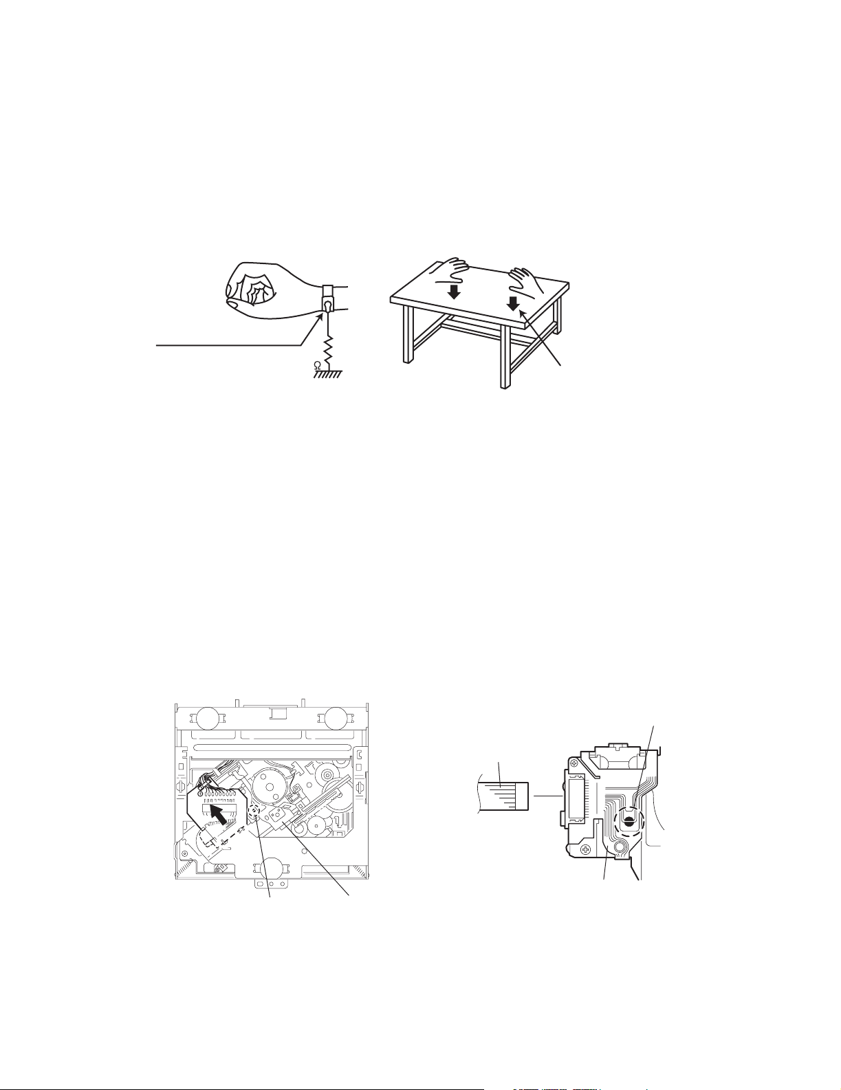
1.2.1 Grounding to prevent damage by static electricity
Static electricity in the work area can destroy the optical pickup (laser diode) in devices such as DVD players.
Be careful to use proper grounding in the area where repairs are being performed.
(1) Ground the workbench
Ground the workbench by laying conductive material (such as a conductive sheet) or an iron plate over it before placing the
traverse unit (optical pickup) on it.
(2) Ground yourself
Use an anti-static wrist strap to release any static electricity built up in your body.
(caption)
Anti-static wrist strap
1M
Conductive material
(conductive sheet) or iron plate
(3) Handling the optical pickup
• In order to maintain quality during transport and before installation, both sides of the laser diode on the replacement optical
pickup are shorted. After replacement, return the shorted parts to their original condition.
(Refer to the text.)
• Do not use a tester to check the condition of the laser diode in the optical pickup. The tester's internal power source can easily
destroy the laser diode.
1.3 Handling the traverse unit (optical pickup)
(1) Do not subject the traverse unit (optical pickup) to strong shocks, as it is a sensitive, complex unit.
(2) Cut off the shorted part of the flexible cable using nippers, etc. after replacing the optical pickup. For specific details, refer to the
replacement procedure in the text. Remove the anti-static pin when replacing the traverse unit. Be careful not to take too long
a time when attaching it to the connector.
(3) Handle the flexible cable carefully as it may break when subjected to strong force.
(4) I t is not possible to adjust the semi-fixed resistor that adjusts the laser power. Do not turn it.
1.4 Attention when traverse unit is decomposed
*Please refer to "Disassembly method" in the text for the CD pickup unit.
• Apply solder to the short land before the flexible wire is disconnected from the connector on the CD pickup unit.
(If the flexible wire is disconnected without applying solder, the CDpickup may be destroyed by static electricity.)
• In the assembly, be sure to remove solder from the short land after connecting the flexible wire.
Short-circuit point
(Soldering)
Flexible wire
Short-circuit point
Pickup
Pickup
(No.49781)1-3

KD-SX9350,KD-SX990
Disassembly method
2.1 Main body
2.1.1 Removing the front panel assembly
(See Fig.1)
(1) Push the detach button in the left right part of the front pan-
el and remove the front panel assembly in the direction of
the arrow.
2.1.2 Removing the front chassis assembly
(See Figs.2 to 4)
• Prior to performing the following procedure, remove the front
panel assembly.
(1) Remove the screw A on the both sides of the main body.
(2) Remove the two screws B on the front side of the main
body.
(3) Release the two joints a and two joints b on both sides of
the main body using a screwdriver, and remove the front
chassis assembly forward.
SECTION 2
Front panel assembly
Detach button
Fig.1
Joint a
A
Joint b
A
Joint b
Front chassis assembly
B
Joint a
Front chassis assembly
Fig.2
Fig.3
Fig.4
1-4 (No.49781)
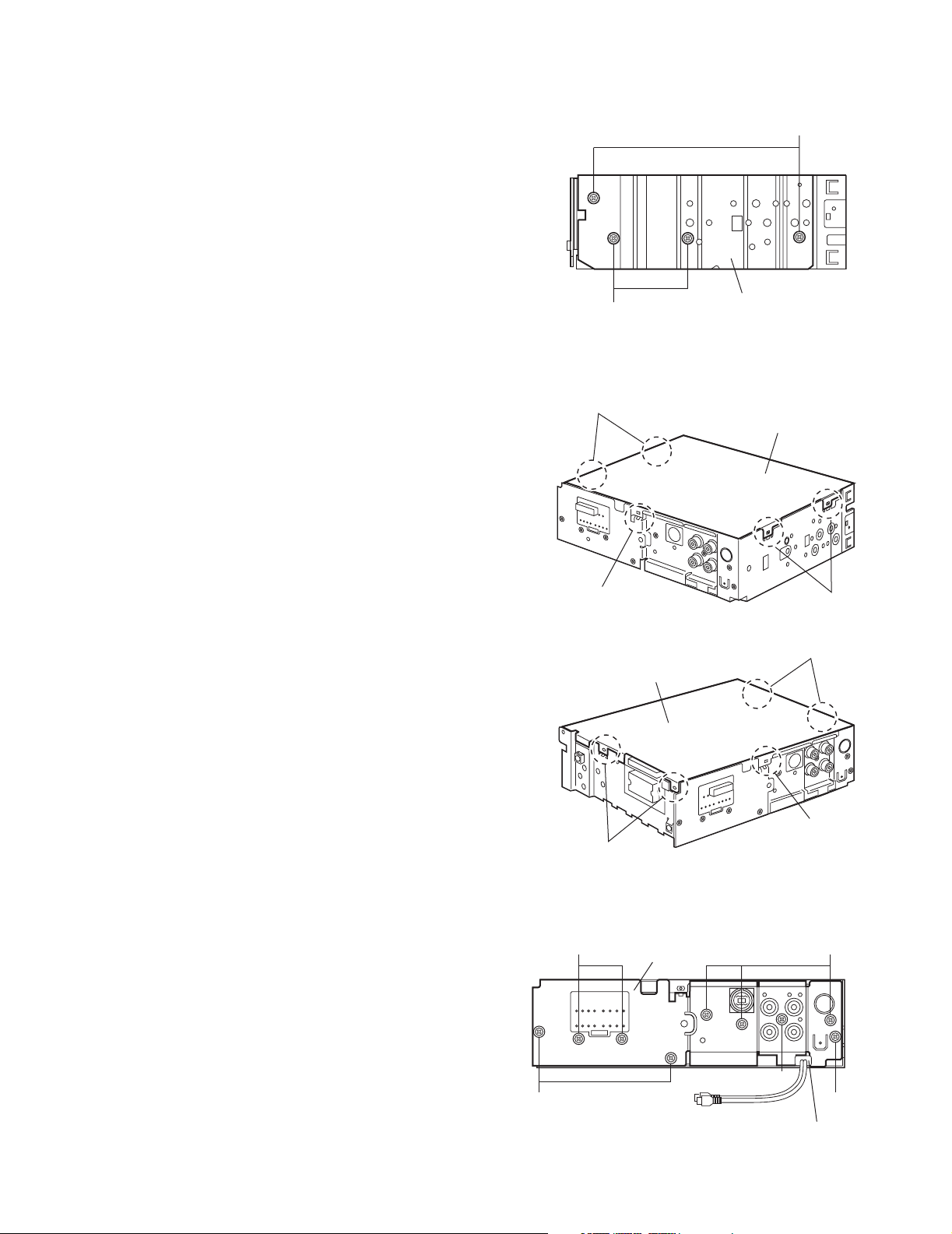
2.1.3 Removing the heat sink
(See Fig.5)
(1) Remove the two screws C and two screws D on the left
side of the main body.
KD-SX9350,KD-SX990
C
2.1.4 Removing the bottom cover
(See Figs.6 and 7)
• Prior to performing the following procedure, remove the front
panel assembly, front chassis assembly and heat sink.
(1) Turn over the body and release the two joints c, two joints
d and joint e .
CAUTION:
Do not damage the main board when releasing the joint e using a screwdriver. (See Figs.6 and 7)
Joint c
Joint e
D
Heat sink
Fig.5
Bottom cover
Joint d
Fig.6
Joint d
Bottom cover
2.1.5 Removing the rear bracket
(See Fig.8)
• Prior to performing the following procedure, remove the front
panel assembly, front chassis assembly, heat sink and bottom
cover.
(1) Remove the three screws E, three screws F and three
screws G on the back of the main body.
(2) Remove the rear bracket.
Reference:
During reassembly, before fixing the rear bracket onto the
main body, insert the Subwoofer cable into the slot. (KDSX9350 only)
Joint e
Joint c
Fig.7
FG
Rear bracket
F
EE
Insert Subwoofer cable
into the slot.
Fig.8
(No.49781)1-5

KD-SX9350,KD-SX990
2.1.6 Removing the main board
(See Fig.9)
• Prior to performing the following procedure, remove the front
panel assembly, front chassis assembly, heat sink, bottom
cover and rear bracket
(1) Remove the two screws H attaching the main board.
(2) Disconnect the connector CN101 and remove the main
board.
2.1.7 Removing the CD mecha board
(See Fig. 10)
• Prior to performing the following procedure, remove the front
panel assembly, front chassis assembly, heat sink, bottom
cover, rear bracket and main board.
(1) Remove the five screws J attaching the CD mecha board.
(2) Disconnect the card wire from the mecha connector.
(3) Move the CD mecha board in the direction of the arrow to
release it from the joint f.
CN101
H
Joint f
Mecha
connector
Main board
H
Fig.9
J
2.1.8 Removing the CD mechanism assembly
(See Fig. 11)
• Prior to performing the following procedure, remove the front
panel assembly, front chassis assembly, heat sink, bottom
cover, rear bracket, main board and CD mecha board.
(1) Remove the three screws K.
Card wire
CD mecha board
CD mechanism assembly
Top chassis
J
Fig.10
K
Top chassis
K
Fig.11
1-6 (No.49781)
2.1.9 Removing the front board
(See Figs. 12 to 14)
• Prior to performing the following procedure, remove the front
panel assembly.
(1) Remove the four screws L on the back side of the front
panel assembly.
(2) Release the nine joints g.
(3) Take out the front board.
KD-SX9350,KD-SX990
L
Joint g
Rear cover
L
Front board
Joint g
L
Fig.12
Joint g
Joint g
Fig.13
Fig.14
(No.49781)1-7
KD-SX9350,KD-SX990
A
2.2 CD Mechanism section
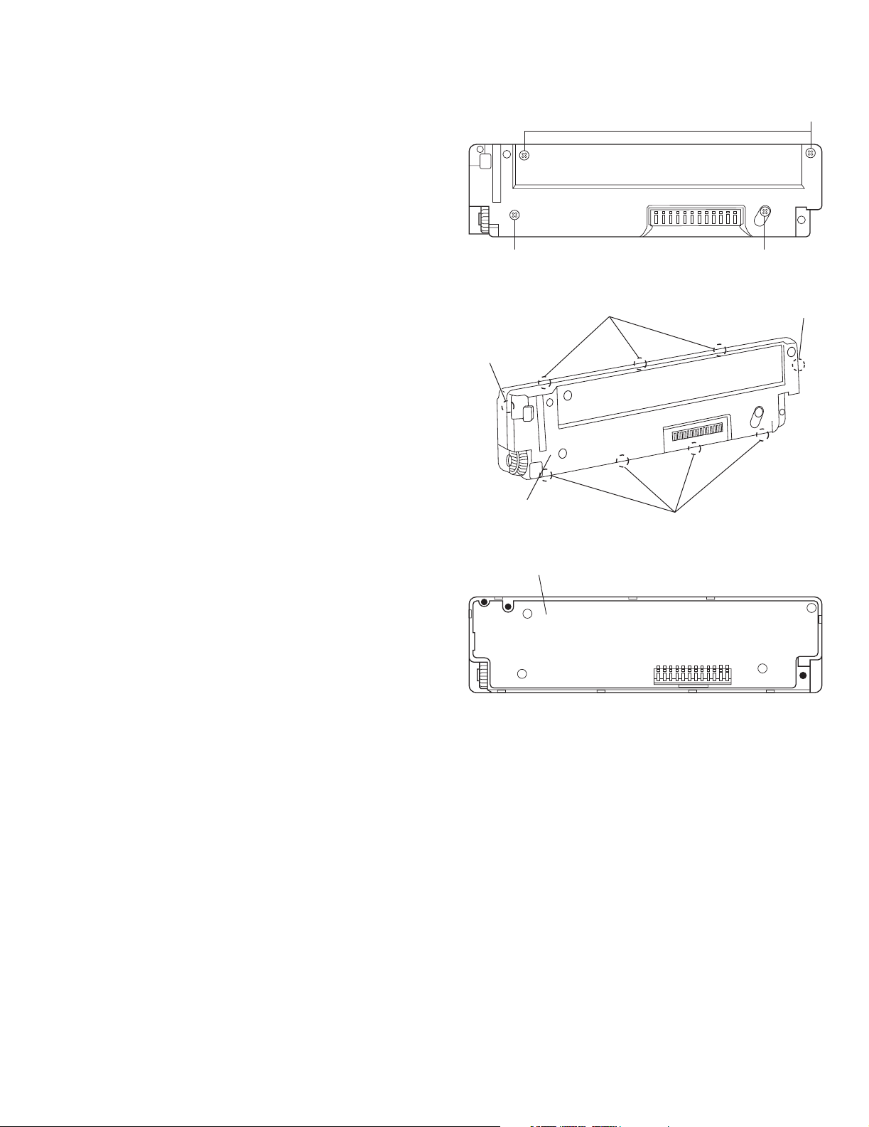
2.2.1 Removing the top cover
(See Figs.1 and 2)
(1) Remove the two screws A on the both side of the body.
(2) Lift the front side of the top cover and move the top cover
backward to release the two joints a.
Top cover
Joints a
A
Joints a
A
Fig.1
Fig.2
Top cover
1-8 (No.49781)

KD-SX9350,KD-SX990
2.2.2 Removing the connector board
(See Figs.3 to 5)
CAUTION:
Before disconnecting the flexible wire from the pickup, solder
the short-circuit point on the pickup. No observance of this instruction may cause damage of the pickup.
(1) Remove the screw B fixing the connector board.
(2) Solder the short-circuit point on the pickup.
(3) Disconnect the flexible wire from the pickup.
(4) Move the connector board in the direction of the arrow to
release the two joints b.
(5) Unsolder the wires on the connector board if necessary.
CAUTION:
Unsolder the short-circuit point after reassembling.
B
Connector board
Flexible wire
Wires
Joints b
Short-circuit point
Fig.3
Short-circuit point
(Soldering)
Pickup
Flexible wire
Frame
Pickup
Fig.4
B
Connector board
Fig.5
(No.49781)1-9

KD-SX9350,KD-SX990
2.2.3 Removing the DET switch
(See Figs.6 and 7)
(1) Extend the two tabs c of the feed sw. holder and pull out
the switch.
(2) Unsolder the DET switch wire if necessary.
DET
switch
Connector
board
Pickup
Fig.6
DET switch
Tab c
Tab c
DET switch wire
Feed sw. holder
Fig.7
1-10 (No.49781)
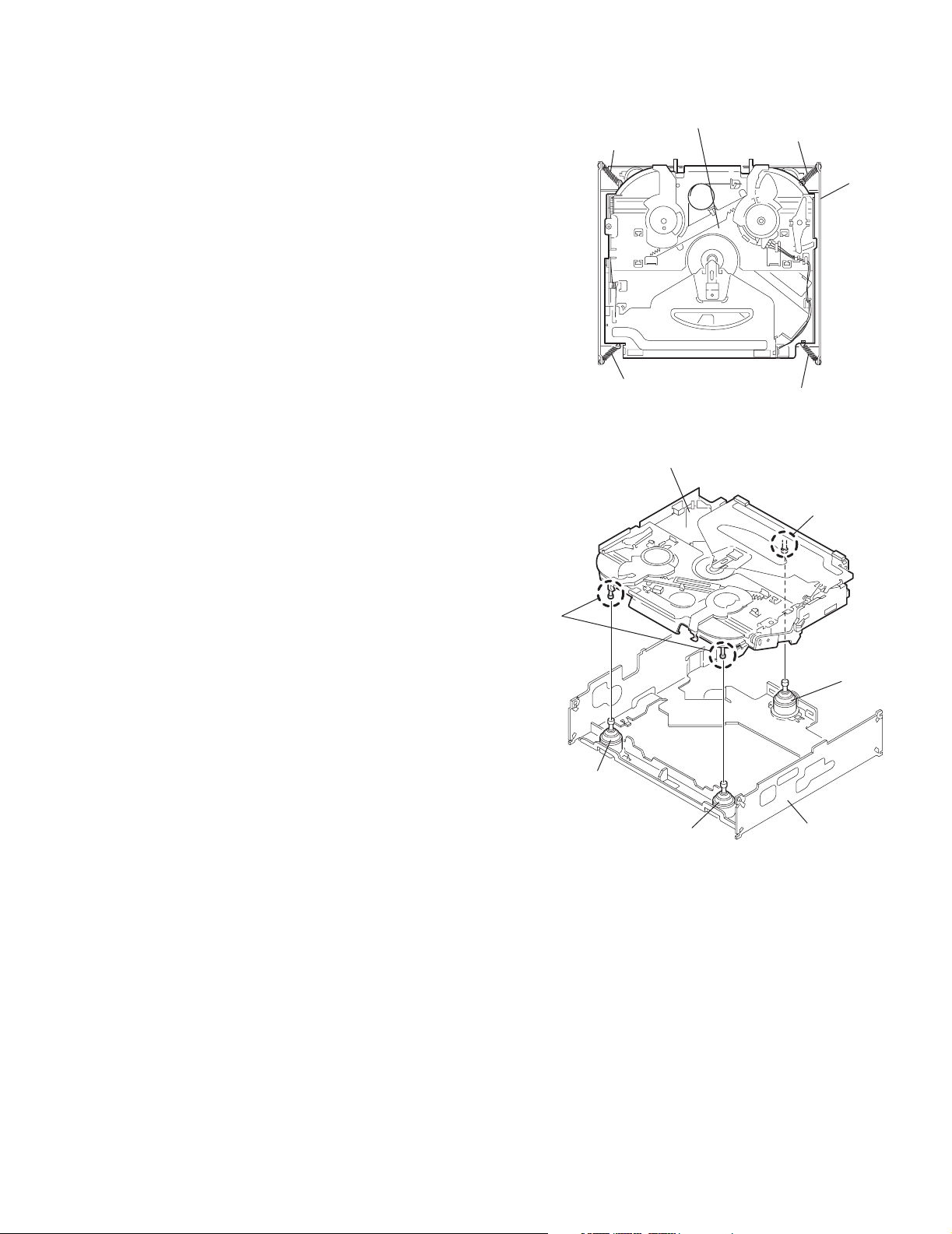
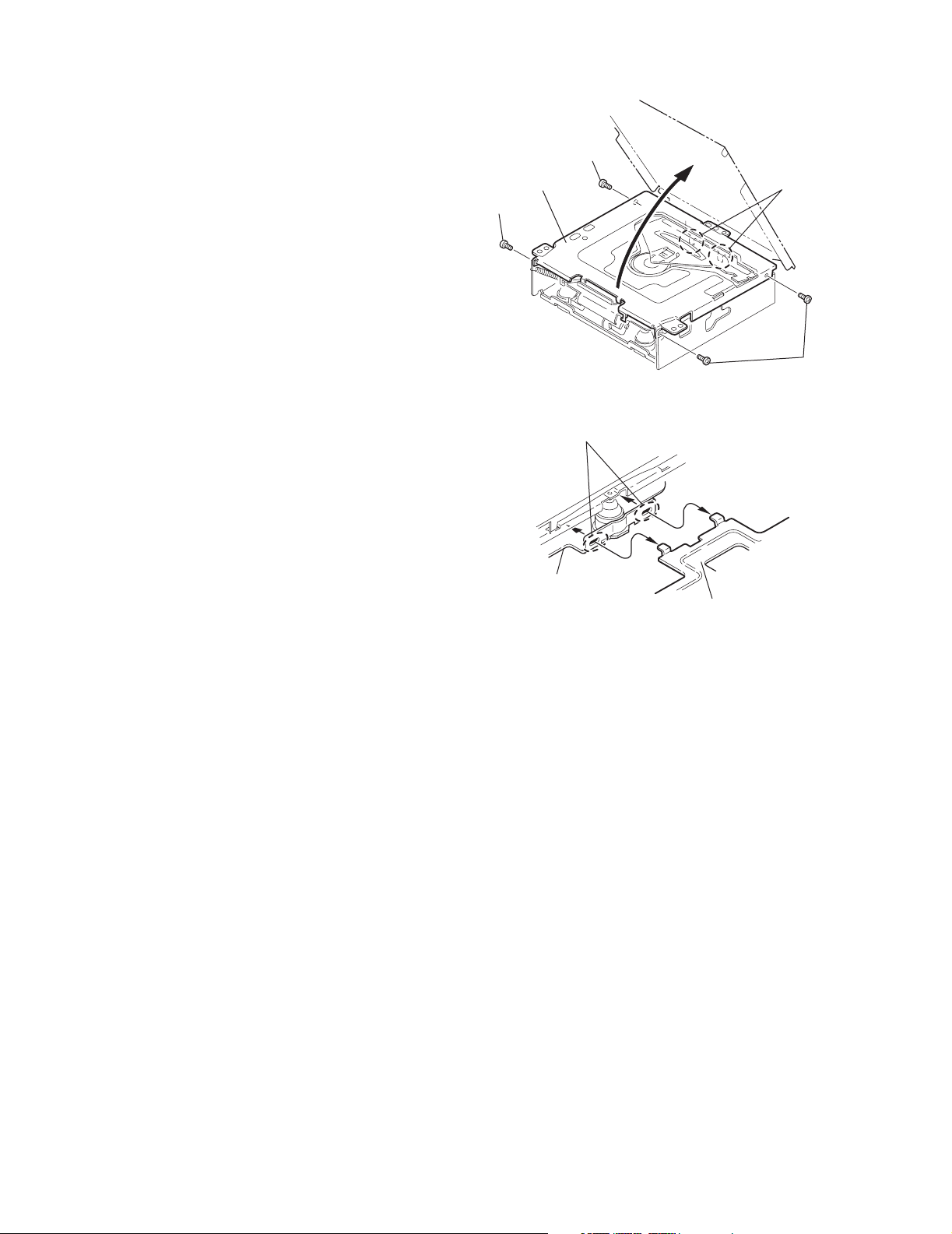
2.2.4 Removing the chassis unit
r
(See Figs.8 and 9)
• Prior to performing the following procedure, remove the top
cover and connector board.
(1) Remove the two suspension springs (L) and (R) attaching
the chassis unit to the frame.
CAUTION:
• The shape of the suspension spring (L) and (R) are different. Handle them with care.
• When reassembling, make sure that the three shafts
on the underside of the chassis unit are inserted to the
dampers certainly.
Suspension spring (R)
KD-SX9350,KD-SX990
Chassis unit
Suspension spring (L)
Frame
Suspension spring (R)
Chassis unit
Shafts
Damper
Damper
Suspension spring (L)
Fig.8
Shaft
Dampe
Frame
Fig.9
(No.49781)1-11

KD-SX9350,KD-SX990
2.2.5 Removing the clamper assembly
(See Figs.10 and 11)
• Prior to performing the following procedure, remove the top
cover.
(1) Remove the clamper arm spring.
(2) Move the clamper assembly in the direction of the arrow to
release the two joints d.
Clamper arm
spring
Joint d
Clamper assembly
Fig.10
Clamper arm spring
Chassis rivet
assembly
Joint d
Joint d
Chassis rivet assembly
Clamper assembly
Joint d
Fig.11
1-12 (No.49781)
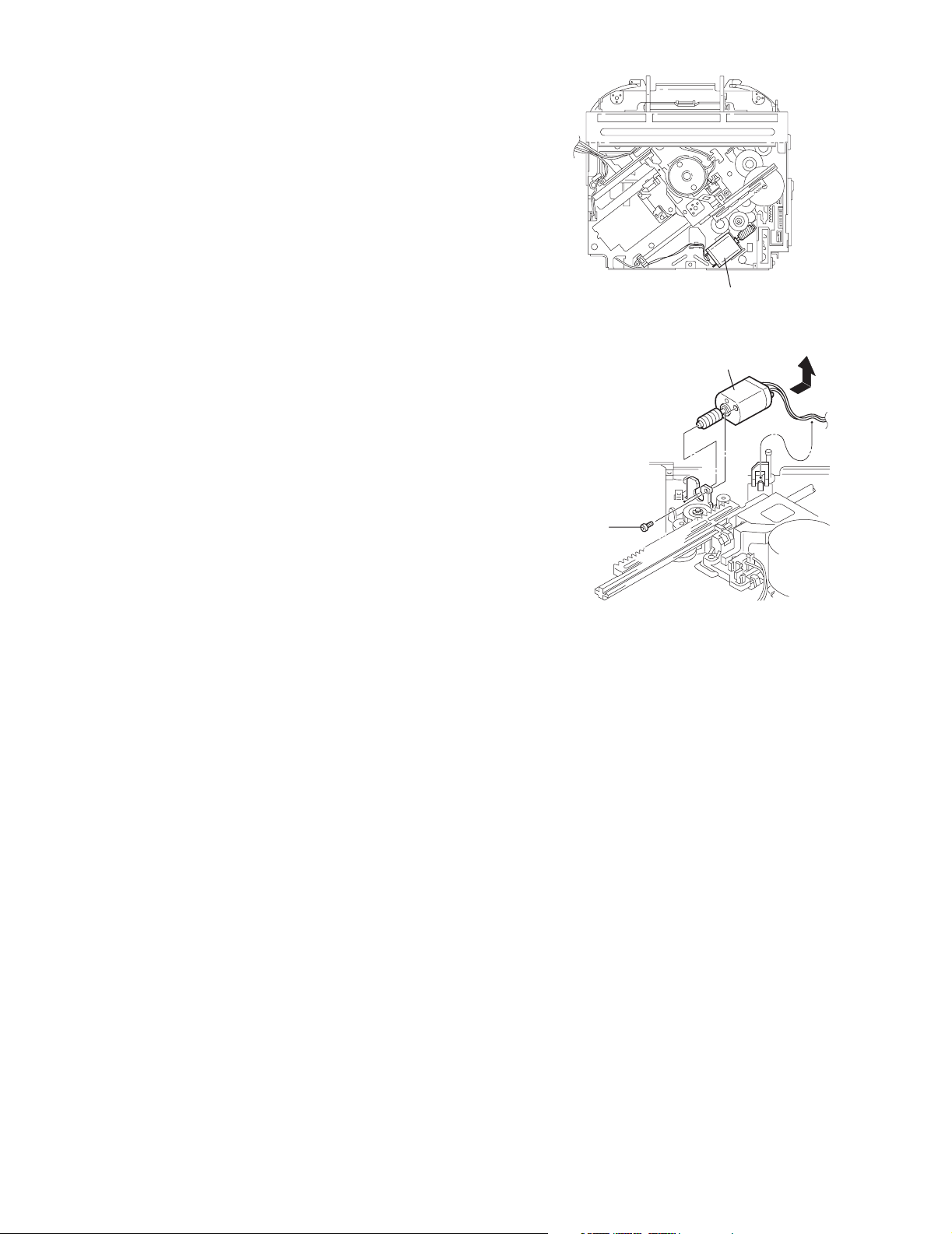
2.2.6 Removing the loading / feed motor assembly
(See Figs.12 and 13)
• Prior to performing the following procedure, remove the top
cover, connector board and chassis unit.
(1) Remove the screw C and move the loading / feed motor as-
sembly in the direction of the arrow to remove it from the
chassis rivet assembly.
(2) Disconnect the wire from the loading / feed motor assembly
if necessary.
CAUTION:
When reassembling, connect the wire from the loading /
feed motor assembly to the frame as shown in Fig.12.
KD-SX9350,KD-SX990
Loading / feed motor assembly
Fig.12
Loading / feed motor assembly
C
Fig.13
(No.49781)1-13

KD-SX9350,KD-SX990
r
2.2.7 Removing the pickup unit
(See Figs.14 to 18)
• Prior to performing the following procedure, remove the top
cover, connector board and chassis unit.
(1) Remove the screw D and pull out the pu. shaft holder from
the pu. shaft.
(2) Remove the screw E attaching the feed sw. holder.
(3) Move the part e of the pickup unit upward with the pu. shaft
and the feed sw. holder, then release the joint f of the feed
sw. holder in the direction of the arrow. The joint g of the
pickup unit and the feed rack is released, and the feed sw.
holder comes off.
(4) Remove the pu. shaft from the pickup unit.
(5) Remove the screw F attaching the feed rack to the pickup
unit.
2.2.8 Reattaching the pickup unit
(See Figs.14 to 17)
(1) Reattach the feed rack to the pickup unit using the screw F.
(2) Reattach the feed sw. holder to the feed rack while setting
the joint g to the slot of the feed rack and setting the joint f
of the feed rack to the switch of the feed sw. holder correctly.
(3) As the feed sw. holder is temporarily attached to the pickup
unit, set to the gear of the joint g and to the bending part of
the chassis (joint h) at a time.
CAUTION:
Make sure that the part i on the underside of the feed
rack is certainly inserted to the slot j of the change lock
lever.
(4) Reattach the feed sw. holder using the screw E.
(5) Reattach the pu. shaft to the pickup unit. Reattach the pu.
shaft holder to the pu. shaft using the screw D.
Feed sw. holder
Part e
Joint g
Feed sw. holder
Feed rack
Part i
E
Slot j
F
Feed sw. holder
Fig.15
Pu. shaft
Pickup unit
Joint f
Joint h
Fig.16
Feed rack
Pickup unit
D
Pu. shaft holde
Joint f
Pu. shaft
D
Pu. shaft holder
Pickup unit
Fig.14
Part e
E
Joint g
Pickup unit
Feed rack
Fig.17
Pickup unit
Joint g
Joint f
Feed sw. holder
Fig.18
1-14 (No.49781)

KD-SX9350,KD-SX990
r
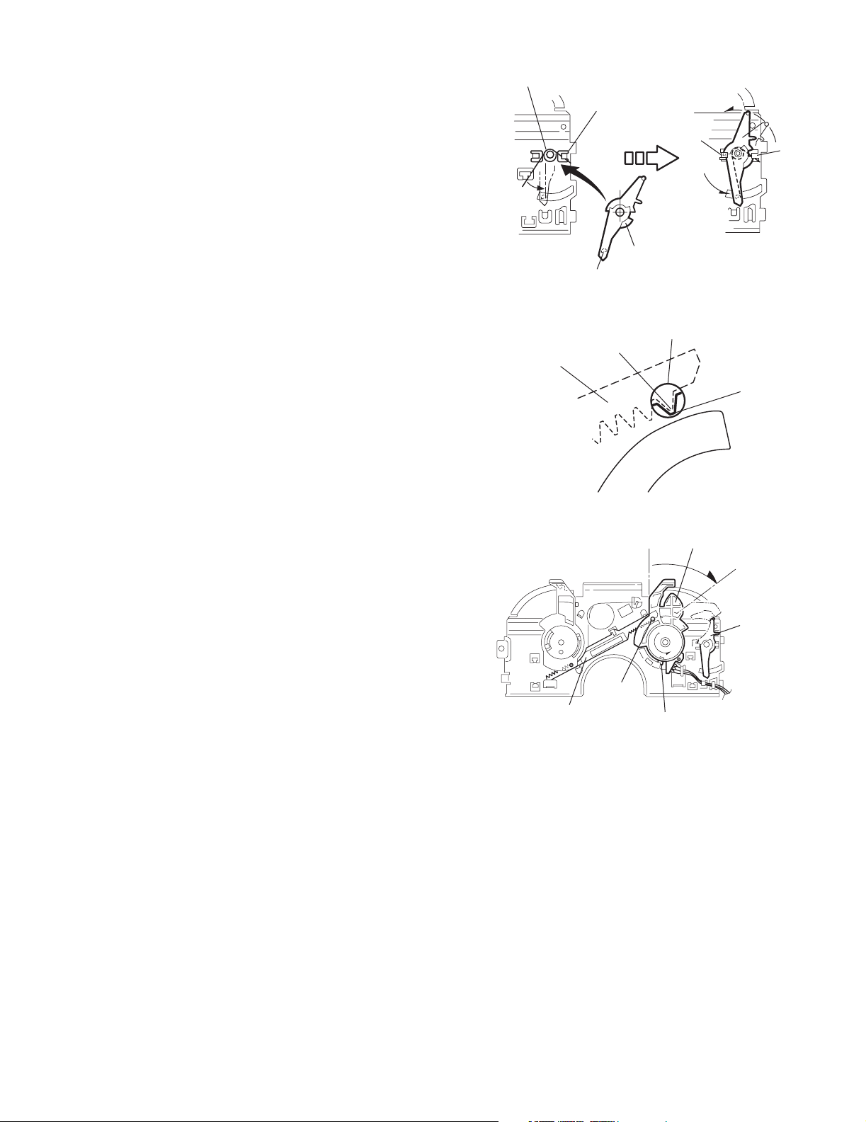
2.2.9 Removing the trigger arm
(See Figs.19 and 20)
• Prior to performing the following procedure, remove the top
cover, connector board and clamper unit.
(1) Turn the trigger arm in the direction of the arrow to release
the joint k and pull out upward.
CAUTION:
When reassembling, insert the part m and n of the trigger
arm into the part p and q at the slot of the chassis rivet
assembly respectively and join the joint k at a time.
Chassis rivet assembly
Trigger arm
Chassis
rivet
assembly
Joint k
Trigger arm
Fig.19
Part p
Part q
Part m
Part n
2.2.10 Removing the top plate assembly
(See Fig.21)
• Prior to performing the following procedure, remove the top
cover, connector board, chassis unit, and clamper assembly.
(1) Remove the screw H.
(2) Move the top plate assembly in the direction of the arrow to
release the two joints r.
(3) Unsolder the wire marked s if necessary.
H
Fig.20
Top plate assembly
Joints
s
Fig.21
(No.49781)1-15

KD-SX9350,KD-SX990
2.2.11 Removing the mode sw. / select lock arm
(See Figs.22 and 23)
• Prior to performing the following procedure, remove the top
plate assembly.
(1) Bring up the mode sw. to release from the link plate (joint t)
and turn in the direction of the arrow to release the joint u.
(2) Unsolder the wire of the mode sw. marked s if necessary.
(3) Turn the select lock arm in the direction of the arrow to re-
lease the two joints v.
(4) The select lock arm spring comes off the select lock arm at
the same time.
Top plate
Link plate
Joint u
Joint t
s
Fig.22
Select lock arm
Select lock arm
Mode sw.
Select lock arm
Top plate
Hook w
Select lock
arm spring
Link plate
Joints v
Fig.23
1-16 (No.49781)
KD-SX9350,KD-SX990
2.2.12 Reassembling the mode sw. / select lock arm
(See Figs.24 to 26)
REFERENCE:
Reverse the above removing procedure.
(1) Reattach the select lock arm spring to the top plate and set
the shorter end of the select lock arm spring to the hook w
on the top plate.
(2) Set the other longer end of the select lock arm spring to the
boss x on the underside of the select lock arm, and join the
select lock arm to the slots (joint v). Turn the select lock
arm as shown in the figure.
(3) Reattach the mode sw. while setting the part t to the first
peak of the link plate gear, and join the joint u.
CAUTION:
When reattaching the mode sw., check if the points y and
z are correctly fitted and if each part operates properly.
Select lock arm spring
Hook w
Joint v
Joint v
Select lock arm
Boss x
Fig.24
Joint t
Point y
Link plate
Point z
Link plate
Fig.25
Mode sw.
Select
lock arm
Joint t
Joint u
Fig.26
(No.49781)1-17
 Loading...