

Page 1

4-084-917-12
Digital High Definition
Digital High Definition
Projection TV
Projection TV
Operating Instructions
Operating Instructions
KDP-57XBR2 KDP-65XBR2
Page 2

Page 3
WARNING
To reduce the risk of fire or shock hazard, do not expose the
projection TV to rain or moisture.
CAUTION
RISK OF ELECTRIC SHOCK
DO NOT OPEN
ATTENTION
RISQUE DE CHOC ELECTRIQUE,
NE PAS OUVRIR
PRECAUCION
RIESGO DE CHOQUE ELECTRICO
NO ABRIR
CAUTION: TO REDUCE THE RISK OF ELECTRIC SHOCK,
DO NOT REMOVE COVER (OR BACK).
NO USER-SERVICEABLE PARTS INSIDE.
REFER SERVICING TO QUALIFIED SERVICE PERSONNEL.
This symbol is intended to alert the user to the
presence of uninsulated “dangerous voltage”
within the product’s enclosure that may be of
sufficient magnitude to constitute a risk of
electric shock to persons.
This symbol is intended to alert the user to the
presence of important operating and maintenance
(servicing) instructions in the literature
accompanying the appliance.
CAUTION
To prevent electric shock, do not use this polarized AC plug with
an extension cord, receptacle or other outlet unless the blades can
be fully inserted to prevent blade exposure.
CAUTION
When using TV games, computers, and similar
products with your projection TV, or viewing a
TV station whose logo always stays on the
screen, keep the brightness and contrast
functions at low settings. If a fixed (non-moving)
pattern such as a station logo is left on the screen
for long periods of time, especially at a high
brightness or contrast setting, the image can be
permanently imprinted onto the screen. These
types of imprints are not covered by your
warranty.
Note on Caption Vision
This television receiver provides display of television closed
captioning in accordance with §15.119 of the FCC rules.
Note on Convergence Adjustment
Before you use your projection TV, make sure to adjust
convergence. For details, see “Adjusting the Convergence
Automatically (Flash Focus)” on page 36.
Note to CATV System Installer
This reminder is provided to call the CATV system installer’s
attention to Article 820-40 of the NEC that provides guidelines for
proper grounding and, in particular, specifies that the cable ground
shall be connected to the grounding system of the building, as close
to the point of cable entry as practical.
Use of this television receiver for other than private viewing of
programs broadcast on UHF or VHF or transmitted by cable
companies for the use of the general public may require
authorization from the broadcaster/cable company and/or
program owner.
NOTIFICATION
This equipment has been tested and found to comply with the
limits for a Class B digital device pursuant to Part 15 of the FCC
Rules. These limits are designed to provide reasonable protection
against harmful interference in a residential installation. This
equipment generates, uses, and can radiate radio frequency energy
and, if not installed and used in accordance with the instructions,
may cause harmful interference with radio communications.
However, there is no guarantee that interference will not occur in a
particular installation. If this equipment does cause harmful
interference to radio or television reception, which can be
determined by turning the equipment off and on, the user is
encouraged to try to correct the interference by one or more of the
following measures:
❑ Reorient or relocate the receiving antennas.
❑ Increase the separation between the equipment and receiver.
❑ Connect the equipment into an outlet on a circuit different
from that to which the receiver is connected.
❑ Consult the dealer or an experienced radio/TV technician for
help.
You are cautioned that any changes or modifications not expressly
approved in this manual could void your authority to operate this
equipment.
Page 4
Safety
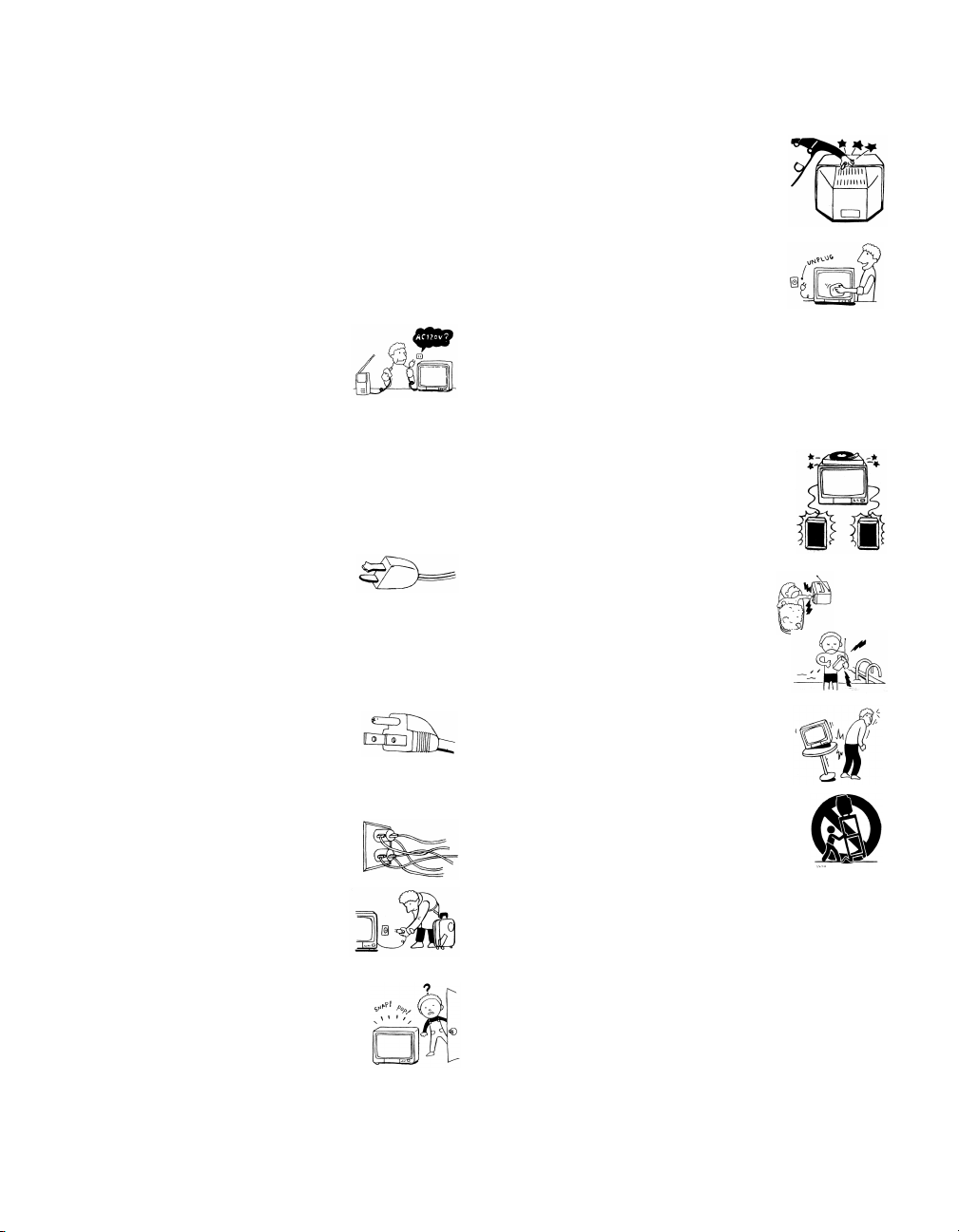
Operate the projection TV only on 120 V AC.
❑
❑ The plug is designed, for safety purposes, to fit into the wall
outlet only one way. If you are unable to insert the plug fully
into the outlet, contact your dealer.
❑ If any liquid or solid object should fall inside the cabinet,
unplug the projection TV immediately and have it checked
by qualified service personnel before operating it further.
❑ If you will not be using the projection TV for several days,
disconnect the power by pulling the plug itself. Never pull on
the cord.
❑ For details concerning safety precautions, see “Important
Safeguards.”
Installing
To prevent internal heat buildup, do not block the ventilation
❑
openings.
❑ Do not install the projection TV in a hot or humid place, or in
a place subject to excessive dust or mechanical vibration.
❑ Avoid operating the projection TV at temperature below 5°C
(41°F).
❑ If the projection TV is transported directly from a cold to a
warm location, or if the room temperature changes suddenly,
the picture may be blurred or show poor color. In this case,
please wait a few hours to let the moisture evaporate before
turning on the projection TV.
❑ To obtain the best picture, do not expose the screen to direct
illumination or direct sunlight. It is recommended to use spot
lighting directed down from the ceiling or to cover the
windows that face the screen with opaque drapery. It is
desirable to install the projection TV in a room where the
floor and walls are not of a reflective material.
As an ENERGY STAR Partner,
Sony has determined that this
product or product models meets
NERGY STAR guidelines
the E
for energy efficiency.
ENERGY STAR is a U.S. registered mark.
®
®
®
Trademark Information
Manufactured under license from Dolby
Laboratories Licensing Corporation.
Dolby and the double-D symbol are
trademarks of Dolby Laboratories
Licensing Corporation.
XBR is a registered trademark and CineMotion is a trademark of
Sony.
i.LINK is a trademark of Sony used only to designate that a
product contains an IEEE 1394 connector. All products with an
i.LINK connector may not communicate with each other.
Owner’s Record
The model and serial numbers are located at the rear of the
projection TV, below the Sony logo, on the sticker, and also on the
TV box (white label). Record these numbers in the spaces provided
below. Refer to them whenever you call upon your Sony dealer
regarding this product.
Model No.
Serial No.
Page 5
Important Safeguards
For your protection, please read these instructions completely, and
keep this manual for future reference.
Carefully observe and comply with all warnings, cautions and
instructions placed on the set or described in the operating
instructions or service manual.
WARNING
To guard against injury, the following basic safety precautions
should be observed in the installation, use and servicing of the set.
Use
Power Sources
This set should be operated only from the type
of power source indicated on the serial/model
plate. If you are not sure of the type of electrical
power supplied to your home, consult your
dealer or local power company. For those sets
designed to operate from battery power, refer
to the operating instructions.
Grounding or Polarization
This set is equipped with a polarized AC power cord plug (a plug
having one blade wider than the other), or with a three-wire
grounding type plug (a plug having a third pin for
grounding).Follow the instructions below:
For the set with a polarized AC power cord plug
This plug will fit into the power outlet only one
way. This is a safety feature. If you are unable to
insert the plug fully into the outlet, try reversing
the plug. If the plug still fails to fit, contact your electrician to have
a suitable outlet installed. Do not defeat the safety purpose of the
polarized plug by forcing it in.
Alternate Warning
For the set with a three-wire grounding type AC plug
This plug will only fit into a grounding-type
power outlet. This is a safety feature. If you are
unable to insert the plug into the outlet, contact
your electrician to have a suitable outlet installed.
Do not defeat the safety purpose of the grounding plug.
Overloading
Do not overload wall outlets, extension cords or
convenience receptacles beyond their capacity,
since this can result in fire or electric shock.
Always turn the set off when it is not being
used. When the set is left unattended and
unused for long periods of time, unplug it
from the wall outlet as a precaution against
the possibility of an internal malfunction that
could create a fire hazard.
If a snapping or popping sound from a TV set is
continuous or frequent while the TV is operating,
unplug the TV and consult your dealer or service
technician. It is normal for some TV sets to make
occasional snapping or popping sounds,
particularly when being turned on or off.
Object and Liquid Entry
Never push objects of any kind into the set
through the cabinet slots as they may touch
dangerous voltage points or short out parts that
could result in a fire or electric shock. Never spill
liquid of any kind on the set.
Cleaning
Clean the cabinet of the projection TV with a dry
soft cloth. To remove dust from the screen, wipe
it gently with a soft cloth. Stubborn stains may
be removed with a cloth slightly dampened with
solution of mild soap and warm water. Never
use strong solvents such as thinner or benzine for cleaning.
If the picture becomes dark after using the projection TV for a long
period of time, it may be necessary to clean the inside of the
projection TV. Consult qualified service personnel.
Installation
Attachments
Do not use attachments not recommended by the
manufacturer, as they may cause hazards.
Water and Moisture
Do not use power-line operated sets near
water — for example, near a bathtub,
washbowl, kitchen sink, or laundry tub, in a
wet basement, or near a swimming pool, etc.
Accessories
Do not place the set on an unstable cart, stand,
table or shelf. The set may fall, causing serious
injury to a child or an adult and serious damage
to the set. Use only a cart or stand recommended
by Sony for the specific model of TV. No part of
the TV set should overhang any edge of the TV
cart or stand; any overhanging edge is a safety
hazard. An appliance and cart combination
should be moved with care. Quick stops,
excessive force, and uneven surfaces may cause
the appliance and cart combination to overturn.
Page 6
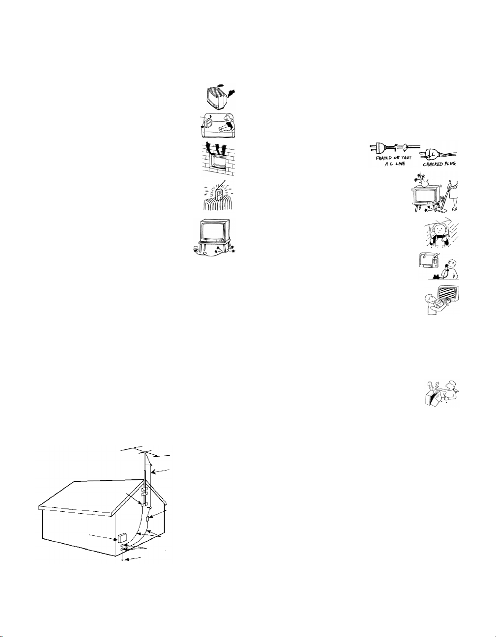
Ventilation
The slots and openings in the cabinet and in the back or bottom are
provided for necessary ventilation. To ensure reliable operation of
the set, and to protect it from overheating, these slots and openings
must never be blocked or covered.
❑ Never cover the slots and openings with a
cloth or other materials.
❑ Never block the slots and openings by
placing the set on a bed, sofa, rug or other
similar surface.
❑ Never place the set in a confined space, such
as a bookcase or built-in cabinet, unless
proper ventilation is provided.
❑ Do not place the set near or over a radiator
or heat register, or where it is exposed to
direct sunlight.
Power-Cord Protection
Do not allow anything to rest on or roll over the
power cord, and do not place the set where the
power cord is subject to wear or abuse.
Antennas
Outdoor Antenna Grounding
If an outdoor antenna is installed, follow the precautions below. An
outdoor antenna system should not be located in the vicinity of
overhead power lines or other electric light or power circuits, or
where it can come in contact with such power lines or circuits.
WHEN INSTALLING AN OUTDOOR ANTENNA SYSTEM,
EXTREME CARE SHOULD BE TAKEN TO KEEP FROM
CONTACTING SUCH POWER LINES OR CIRCUITS AS
CONTACT WITH THEM IS ALMOST INVARIABLY FATAL.
Be sure the antenna system is grounded so as to provide some
protection against voltage surges and built-up static charges.
Section 810 of the National Electrical Code (NEC) in USA and
Section 54 of the Canadian Electrical Code in Canada provides
information with respect to proper grounding of the mast and
supporting structure, grounding of the lead-in wire to an antenna
discharge unit, size of grounding conductors, location of antenna
discharge unit, connection to grounding electrodes, and
requirements for the grounding electrode.
Antenna Grounding According to the NEC
Refer to section 54-300 of Canadian Electrical Code for Antenna
Grounding.
Antenna lead-in wire
Lightning
For added protection for this television receiver during a lightning
storm, or when it is left unattended and unused for long periods of
time, unplug it from the wall outlet and disconnect the antenna.
This will prevent damage to the receiver due to lightning and
power-line surges.
Service
Damage Requiring Service
Unplug the set from the wall outlet and refer servicing to qualified
service personnel under the following conditions:
❑ When the power cord or plug
is damaged or frayed.
❑ If liquid has been spilled into
the set.
❑ If the set has been exposed to
rain or water.
❑ If the set has been subject to
excessive shock by being
dropped, or the cabinet has
been damaged.
❑ If the set does not operate
normally when following the
operating instructions. Adjust
only those controls that are
specified in the operating
instructions. Improper
adjustment of other controls
may result in damage and
will often require extensive
work by a qualified technician
to restore the set to normal operation.
❑ When the set exhibits a distinct change in performance, it
indicates a need for service.
Servicing
Do not attempt to service the set yourself since
opening the cabinet may expose you to dangerous
voltage or other hazards. Refer all servicing to
qualified service personnel.
Replacement Parts
When replacement parts are required, be sure the service
technician certifies in writing that he has used replacement parts
specified by the manufacturer that have the same characteristics as
the original parts.
Unauthorized substitutions may result in fire, electric shock or
other hazards.
Ground clamp
Electrical wire
equipment
NEC: National Electrical Code
Antenna discharge unit
(NEC Section 810-20)
Ground clamps
Antenna lead-in wire
Power service grounding electrode
system (NEC Art 250 Part H)
Page 7
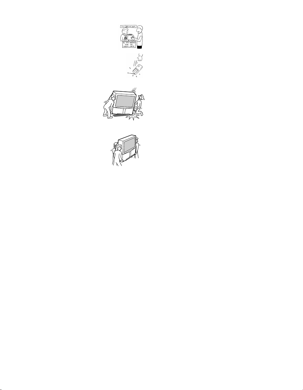
Safety Check
Upon completion of any service or repairs to the
set, ask the service technician to perform routine
safety checks (as specified by the manufacturer) to
determine that the set is in safe operating
condition, and to so certify. When the set reaches
the end of its useful life, improper disposal could
result in a picture tube implosion. Ask a qualified
service technician to dispose of the set.
For Safety
Be careful when moving the projection TV
When you place the projection TV in
position, be careful not to drop it on your
foot or fingers.
Watch your footing while installing the
projection TV.
Carry the projection TV in the specified manner
If you carry the projection TV in a manner
other than the specified manner and
without the specified number of persons, it
may drop and a serious injury may be
caused. Be sure to follow the instructions
mentioned below.
❑ Carry the projection TV with the
specified number of persons (see
page 10).
❑ Do not carry the projection TV holding the speaker grill.
❑ Hold the projection TV tightly when carrying it.
Page 8

Page 9

Contents
Introducing the Projection TV
Overview .......................................................1
Features..........................................................2
Package Contents .........................................3
Using the Remote Control...........................3
Frequently Asked Questions ......................7
Setting Up the Projection TV
Overview .......................................................9
Carrying Your Projection TV....................10
Installing the Projection TV ......................10
Mounting the Rear Speakers
(not supplied).......................................11
Projection TV Controls and Connectors..13
Basic Connections.......................................17
Connecting a VCR and Cable ...................19
Connecting a VCR and Cable Box............20
Connecting Two VCRs for Tape Editing 22
Connecting a Satellite Receiver ................23
Connecting a Satellite Receiver
with a VCR...........................................24
Connecting an Audio Receiver.................25
Connecting a DVD Player with
Component Video Connectors..........26
Connecting a DVD Player with A/V
Connectors............................................27
Connecting a Camcorder...........................28
Connecting a Device with an
Optical IN Connector..........................29
Connecting i.LINK Compatible Devices.30
Using the CONTROL S Feature ...............34
Setting Up the Projection TV
Automatically ......................................35
Adjusting the Convergence
Automatically (Flash Focus) ..............36
Using the Projection TV Features
Overview .....................................................37
Using the Program Guide .........................38
Using the Scrolling Channel Index..........39
Using Favorite Channels...........................40
Using Wide Screen Mode..........................43
Using Twin View........................................44
Using the Freeze Function ........................47
Using the i.LINK Control Panel ...............48
Using the Timer ..........................................49
Using the Projection TV Menus
Overview .....................................................51
Using the Video Menu...............................52
Using the Audio Menu..............................54
Using the Screen Mode Menu ..................56
Using the Channel Setup Menu ...............58
Using the Parental Control Menu............60
Using the Setup Menu ...............................64
Other Information
Overview .....................................................67
Programming the Remote Control ..........68
Operating Other Components with Your
Projection TV Remote Control ..........71
About i.LINK ..............................................73
Troubleshooting..........................................74
Specifications...............................................77
Index.............................................................79
Page 10

Page 11

Introducing the Projection TV
Overview
This chapter gives an overview of the projection TV features, defines
the package contents, describes the remote control, and provides
answers to frequently asked questions.
Topi c Pag e
Features 2
Package Contents 3
Using the Remote Control 3
Frequently Asked Questions 7
1
Page 12

Introducing the Projection TV
Features
Some of the features that you will enjoy with your new projection TV
include:
❑ Built-in Digital Television (DTV) Receiver: You can watch
digital television programs and enjoy the improved audio/video
quality that these programs offer.
❑ Wide Screen Mode: Watch conventional 4:3 aspect ratio
broadcasts in wide screen (16:9) mode.
❑ DRC
™
Multi-Function: Unlike conventional line doublers, the
DRC (Digital Reality Creation) feature doubles vertical and
horizontal lines, resulting in four times the density for quality
sources such as DVD, satellite, and digital camcorder.
❑ Twi n View
™
: Using the Multi-Image Driver (MIDX), Twin View
allows you to watch two programs side by side, with the ability
to zoom in one picture. You can watch pictures from two different
sources (1080i, 720p, 480p, and 480i) simultaneously.
❑ Program Guide: Lets you select digital channels and subchannels
and review program information from an on-screen list.
❑ Scrolling Channel Index
™
: Lets you preview and select
programs from a scrolling index of video pictures.
❑ Favorite Channels: Allows you to preview and select from 16 of
your favorite channels.
❑ Parental Control: V-Chip technology allows parents to block
unsuitable programming for younger viewers.
❑ Component Video Inputs: Offers the best video quality for DVD
(480p, 480i), and digital set-top box (1080i, 720p, 480p, 480i)
connections.
❑ S-VIDEO Inputs: Provides a high-quality video signal from
connected equipment.
❑ CineMotion
™
: Provides optimal picture quality for film-based
sources (media originally shot in 24 frames-per-second format).
❑ i.LINK: Provides a secure digital interface to other digital home
entertainment devices, including digital cable set-top boxes.
i.LINK allows for the secure transfer of copyright-protected highdefinition content between these devices and your digital
television.
❑ Dolby
®
Digital: This TV has a Dolby Digital decoder. By adding
rear speakers and a powered subwoofer, you can enjoy 5.1
channel surround sound from Dolby Digital encoded DTV
programs.
❑ Optical Digital Audio Out: If you have an audio receiver with an
optical digital audio input, you can use it to decode and amplify
the optical digital audio output.
2
Page 13
Introducing the Projection TV
Package Contents
Along with your new projection TV, the package contains a remote
control and two AA batteries. No additional cables are included.
These items are all you need to set up and operate the projection TV
in its basic configuration.
Most components (VCRs, DVD players, etc.) come with the necessary
cables to connect them. If you want to set up a complex system, you
may need to buy extra cables, connectors, etc. Be sure to have these
on hand before you start to connect your system.
Using the Remote Control
Although some of the projection TV’s functionality can be controlled
using buttons located on the front panel of the projection TV (see
page 13), you’ll find the remote control to be more convenient while
watching TV.
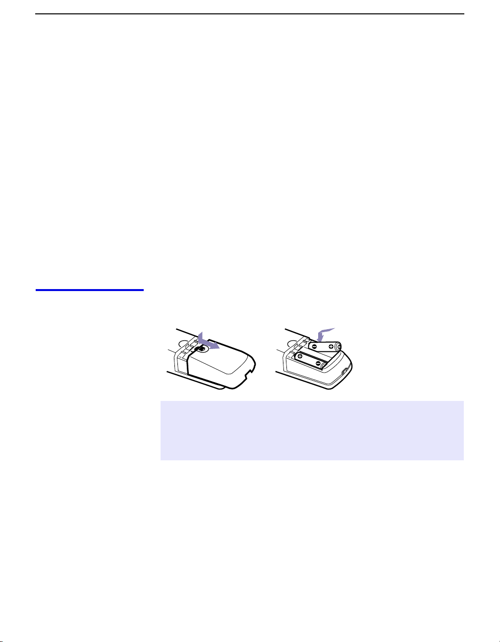
Inserting Batteries Insert two size AA (R6) batteries (supplied) by matching the + and –
on the batteries to the diagram inside the battery compartment.
✍ Remove the batteries to avoid damage from possible battery leakage whenever
you anticipate that the remote control will not be used for an extended period.
Handle the remote control with care; avoid dropping it, getting it wet, placing
it in direct sunlight, near a heater, or where the humidity is high.
3
Page 14
Introducing the Projection TV
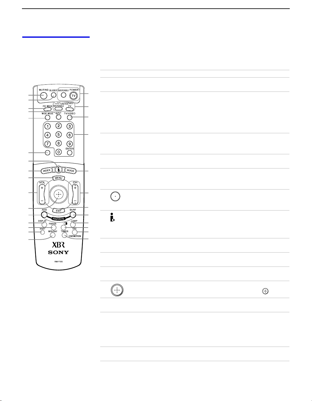
Button Descriptions The following table describes the buttons on the remote control’s
outside and inside panels.
Outside Panel
Button Description
1 MUTING Press to mute the sound. Press again or press VOL+ to
restore the sound.
in minutes (15, 30, 45, 60, or 90) that you want the
projection TV to remain on before shutting off
automatically. Cancel by pressing until Sleep Off appears.
While the Sleep feature is set, press once to view
remaining time.
Vivid, Standard, Movie, Game, Pro. Also available in the Video
menu. For details, see page 52.
CABLE input.
Wide Zoom, Normal, Full, Zoom. Also available in the Screen
Mode menu. For details, see pages 43 and 56.
(for example, 2.1). For details on selecting subchannels,
see page 38.
i.LINK button on the front panel of the projection TV (see
page 13). For details on using the i.LINK Control Panel,
see page 48.
see page 39.
again to exit from the menus. For details, see page 51.
1
2
3
4
5
6
7
8
9
q;
qa
qs
qd
qf
qg
qh
qj
2 SLEEP Press repeatedly until the projection TV displays the time
qk
ql
w;
3 PIC MODE Press repeatedly to step through the video picture modes:
4 ANT Press to change between the VHF/UHF input and the
wa
5 WIDE MODE Press repeatedly to step through the Wide Mode settings:
6 Use with 0 – 9 and ENTER buttons to select subchannels
ws
wd
7 Press to display the i.LINK Control Panel. There is also an
wf
wg
wh
wj
wk
8 INDEX Press to display the Scrolling Channel Index. For details,
9 MENU Press to display the projection TV on-screen menu. Press
0 VOL Press to adjust the volume.
qa Move the joystick B bVv to move the on-screen cursor. To
select an item, press the center of the joystick ( ).
qs ADD
FAVORITE
Press to add the current channel to the Favorite Channels
list. For details, see page 40.
qd DISPLAY Press once to display the channel number, channel label
(if set), time, and other information. When the DTV is
receiving a digital signal with Dolby Digital, the decoding
type is displayed (Dolby Digital or Dolby Digital Pro
Logic). Press again to turn Display off.
qf FREEZE Press to freeze the window picture. Press again to restore
the picture. For details, see page 47.
4
Page 15

Introducing the Projection TV
Button Description
qg RESET Press while a menu is displayed (page 51 to 66) to reset
the settings to the factory defaults. Also used to clear
Favorite Channels (see page 42).
qh MTS/SAP Press repeatedly to step through the Multi-channel TV
Sound (MTS) options: Stereo, Auto SAP, and Mono. Also
available in the Audio menu. For details, see page 54.
qj POWER buttons
(GREEN)
qk FUNCTION
buttons
ql TV/VIDEO
w; 0 – 9 and ENTER Press 0 - 9 to select a channel — the channel changes after
wa GUIDE Press to display the program guide. For details, see
ws CH Press to scan through channels. To scan rapidly through
wd EXIT Press to exit the on-screen menu or display and return to
wf SURF FAVORITE Press to display the Favorite Channels list. For details, see
wg JUMP Press to jump back and forth between two channels. The
wh (TWIN VIEW) Press to turn on and off Twin View. For details, see pages
wj DRC
CINEMOTION
wk TIMER Press to program the projection TV to turn on and off and
Press to turn on and off the projection TV and other
audio/video equipment you have programmed into the
remote control. For instructions, see “Programming the
Remote Control” on page 68.
Press to select the equipment (SAT/CABLE or TV) that
you want to operate. The indicator lights up momentarily
when pushed to show which device the remote control is
operating.
Press repeatedly to step through the video equipment
connected to your projection TV’s video inputs.
2 seconds. Press ENTER to select immediately.
page 38.
channels, press and hold down either CH button.
normal viewing.
page 41.
projection TV alternates between the current channel and
the last channel that was selected.
44 to 46.
Press repeatedly to step through the available highresolution picture modes: Interlaced, Progressive and
CineMotion. Also available in the Video menu. For details,
see page 53.
tune to a specific channel at two scheduled viewing times
(see page 49). Also available in the Setup menu (see
page 66).
5
Page 16
Introducing the Projection TV
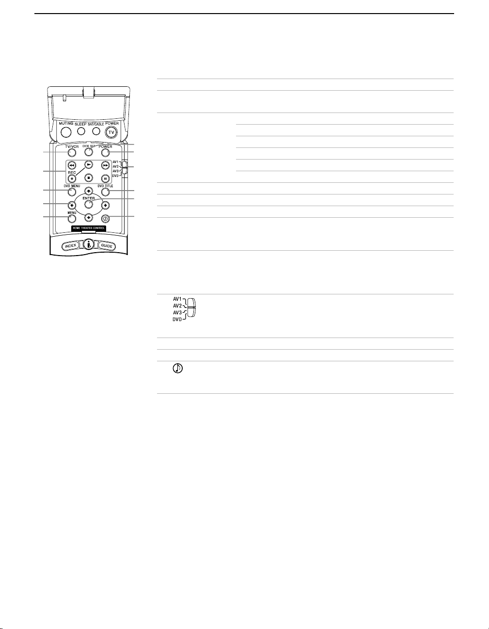
Inside Panel
You can access the following buttons by lifting up the outside panel.
Button Description
1 TV/VCR Press to change the VHF/UHF output of the VCR.
1
2
3
4
5
6
7
8
2 Transport
Buttons
m Rewind
N Play
z Record (press together with N)
x Stop
M Fast-forward
X Pause
3 DVD MENU Press to display the DVD disc menu.
9
q;
4 B bVv Press B bVv to move the on-screen cursor.
5 MENU Press to display the DVD setup menu.
qa
6 CODE SET Used for programming the remote control to operate
non-Sony video equipment. For details, see
“Programming the Remote Control” on page 68.
7 POWER Press to turn on and off other audio/video equipment
you have programmed into the remote control. For
instructions, see “Programming the Remote Control” on
page 68.
8 Use to switch control for connected video equipment.
You can program one video source for each switch
position. For details, see “Programming the Remote
Control” on page 68.
9 DVD TITLE Press to display the DVD title.
0 ENTER Press to select.
qa Press repeatedly to step through the Audio Effect
options: Dolby Surround, Simulated, and Off. Also available
in the Audio menu. For details, see page 54.
6
Page 17

Frequently Asked Questions
Introducing the Projection TV
What is digital TV
(DTV)?
What are the
benefits of DTV?
Digital television (or “DTV”) refers to the over-the-air television
broadcast standards adopted by the Federal Communications
Commission in 1996. Developed by the Advanced Television Systems
Committee (ATSC), a group of manufacturing companies, these
standards define the specifications for 18 digital broadcast formats.
There are six formats in the ATSC DTV standard that are described as
“High Definition Television.” The remaining 12 video formats are
described as “Standard Definition Television.”
Although the technical aspects of these standards are transparent to
television viewers, the benefits are as dramatic as those experienced
when digital music on compact disk was introduced — probably
even more so.
Your Sony projection TV is capable of receiving all 18 formats of
digital TV formats, including high-definition.
For the television viewer, digital TV represents one of the most
significant advances in television since color television replaced black
and white. Here are just a few of the benefits:
❑ Dramatically superior picture quality, with up to six times the
picture detail of today’s analog television.
❑ Multichannel digital sound, including Dolby
❑ Widescreen. DTV can provide the same type of widescreen
presentation as you see in movie theaters. The new screen size
has a 16:9 width-to-height (or “aspect”) ratio, compared with a
4:3 aspect ratio of today’s conventional television. This means
that digital broadcasts of movies no longer need to be
“reformatted” for television.
®
Digital sound.
Do I need a special
antenna to receive
digital television?
No. Initially, digital television will arrive through a standard, overthe-air VHF/UHF antenna, which means you can receive digital
broadcasts using the same terrestrial (“rooftop”) antenna you
currently use to receive conventional programming. However, if you
currently receive your VHF/UHF programming via cable, you will
need to install a VHF/UHF antenna in order to receive digital
programming. Your Sony projection TV, however, is also equipped
with connectors that may allow you to connect DTV-compatible cable
boxes when they become available.
7
Page 18

Introducing the Projection TV
Can this TV receive
conventional analog
broadcasts that are
available today?
When is digital
broadcasting being
introduced?
How can I select
digital channels?
Yes. This TV is designed to receive conventional analog broadcasts,
cable TV, as well as all formats of digital broadcasts. Of course, you
can also connect VCRs, DVD players, digital broadcast (satellite)
receivers, and other audio/video components.
The transition from today’s analog broadcasting system to digital
television will take time to complete. In the fall of 1998, some
networks started to broadcast digital programs.
Digital channels are indicated by the use of a decimal or “dot” in the
subchannel number (for example, “2.1”). This number appears when
you press the
subchannel directly, use the 0-9 buttons, button, and the
button.
For example, to select subchannel 2.1, press:
2 + + 1 + ENTER
You can also select digital channels using an on-screen program
guide. See page 38 for details.
CH +/- buttons or press the DISPLAY button. To select a
ENTER
8
Page 19

Setting Up the Projection TV
Overview
This chapter includes illustrated instructions for setting up your
projection TV.
Topi c Pag e
Carrying Your Projection TV 10
Installing the Projection TV 10
Mounting the Rear Speakers (not supplied) 11
Basic Connections 17
Connecting a VCR and Cable 19
Connecting a VCR and Cable Box 20
Connecti ng Two V CRs for Tape Editing 22
Connecting a Satellite Receiver 23
Connecting a Satellite Receiver with a VCR 24
Connecting an Audio Receiver 25
Connecting a DVD Player with Component Video
Connectors
Connecting a DVD Player with A/V Connectors 27
Connecting a Camcorder 28
Connecting a Device with an Optical IN Connector 29
Connecting i.LINK Compatible Devices 30
Using the CONTROL S Feature 34
Setting Up the Projection TV Automatically 35
Adjusting the Convergence Automatically (Flash Focus) 36
26
9
Page 20
Setting Up the Projection TV
Carrying Your Projection TV
Carrying the projection TV requires three or more people.
The projection TV is equipped with casters for easy movement on a
hard surface. Be sure to move your projection TV using the casters.
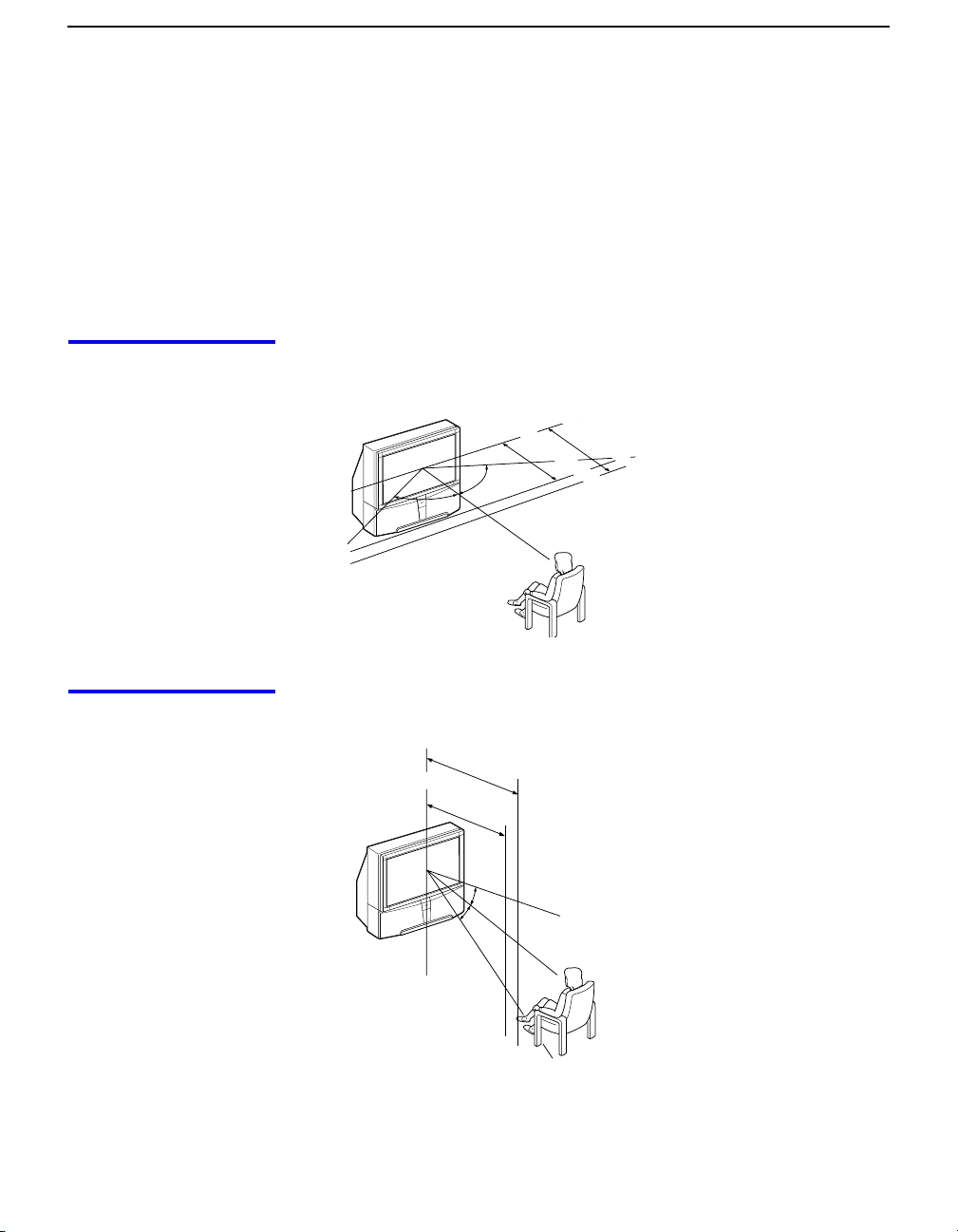
Installing the Projection TV
Recommended
Viewing Area
(Horizontal)
min. 2.4m (approx. 8 ft.)
min. 2.1m (approx. 7 ft.)
65"
57"
60˚
˚
6060
Recommended
Viewing Area
(Vertical)
10
min. 2.4m (approx. 8ft.)
65"
min. 2.1m (approx. 7ft.)
57"
20˚
20˚
Page 21
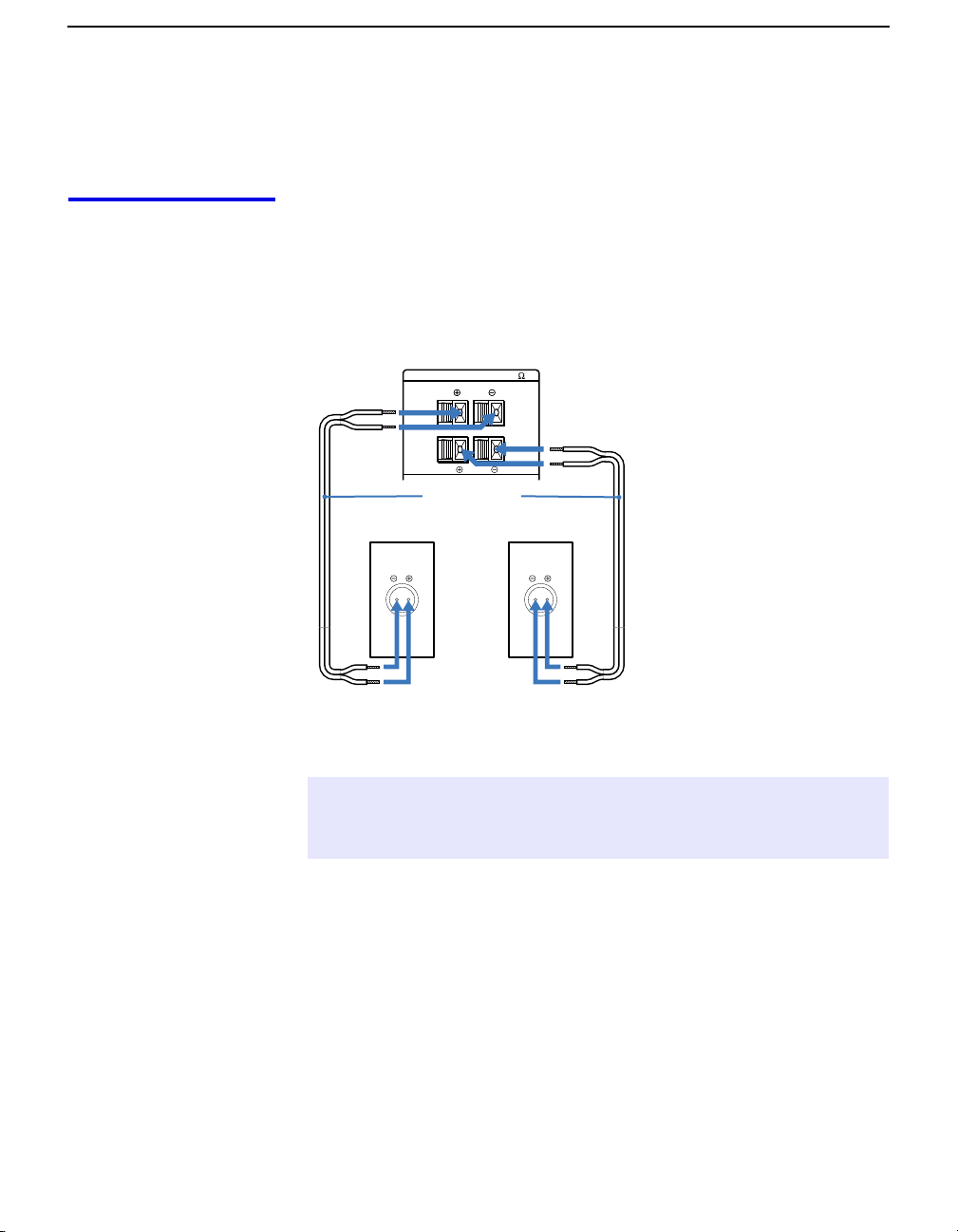
Mounting the Rear Speakers (not supplied)
For surround sound, connect rear speakers to your projection TV.
Setting Up the Projection TV
Connecting the Rear
Speakers
1 Be sure the TV is turned off.
2 Using the speaker cords, connect REAR SPEAKER OUT L on
your projection TV to the speaker terminal on one rear speaker,
and connect REAR SPEAKER OUT R to the terminal on the other
one.
(Rear of projection TV)
REAR SPEAKER OUT(MIN 8
Speaker
SS-MB115
(not supplied)
L
R
Speaker cord
(not supplied)
)
L
R
Speaker
SS-MB115
(not supplied)
✍ If you connect rear speakers other than the ones recommended, be sure the
speakers have a maximum input power of more than 20 W and impedance of 8
ohms.
11
Page 22
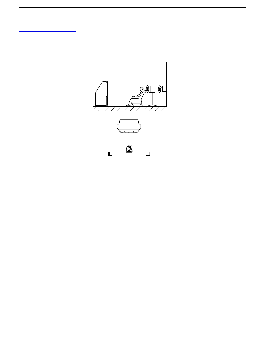
Setting Up the Projection TV
Installation For optimum surround sound effect, mount the rear speakers in the
following places (as shown in the illustration):
❑ On a wall or table, as high as the listener’s ears.
Projection TV
(Rear of projection TV)
Left rear
speaker
Rear speaker
Right rear
speaker
12
Page 23
Setting Up the Projection TV
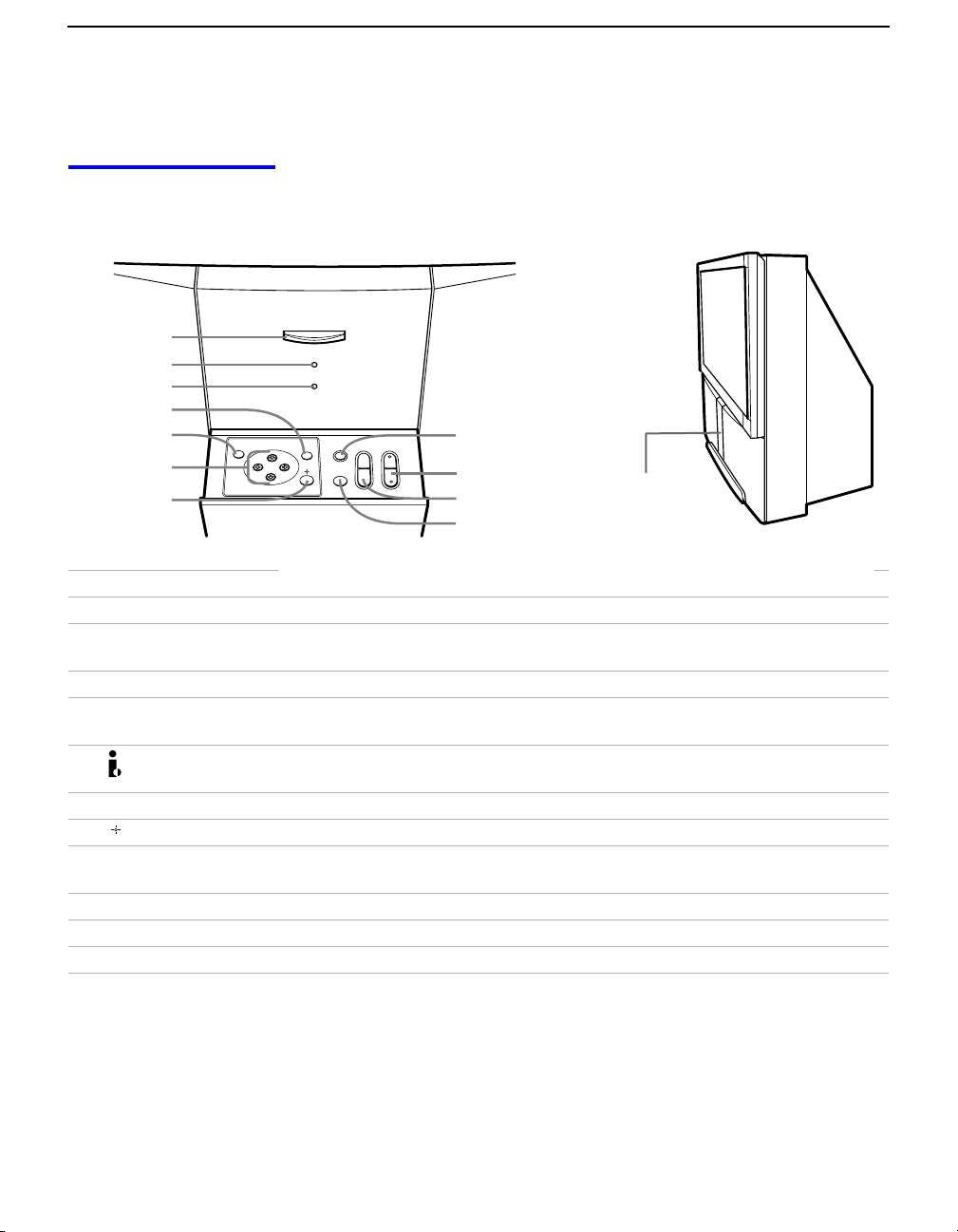
Projection TV Controls and Connectors
Front Panel To access the front buttons and input jacks on the projection TV, push
in to release the door on the front of the projection TV.
1
2
3
POWER
STAND BY/
i.LINK STAND BY
TIMER
4
5
6
7
i.LINK
TV/VIDEO
FLASH FOCUS
CHANNELVOLUME
+
+
–
–
MENU
8
9
q;
Push to open
qa
Control Description
1 POWER Press to turn on and off the projection TV.
2 STANDBY/
i.LINK STANDBY
When lit in orange, indicates that i.LINK Standby is On. When lit in red,
indicates that i.LINK Standby is Off. For details, see page 66.
3 TIMER When lit, indicates one of the timers is set. For details, see page 49.
4 MENU Press to display the projection TV on-screen menu. Press again to exit from
the menus. For details, see page 51.
5 i.LINK Press to display the i.LINK Control Panel. For details on using the i.LINK
Control Panel, see page 48.
6 B bVv Press B bVv to move the on-screen cursor and press SELECT to select.
7 SELECT Press to select the on-screen highlighted item.
8 TV/VIDEO
Press repeatedly to step through the video equipment connected to your
projection TV
’s video inputs.
9 -CHANNEL+ Press to scan through channels.
0 -VOLUME+ Press to adjust the volume.
qa FLASH FOCUS Press to adjust the convergence (see page 36).
13
Page 24
Setting Up the Projection TV
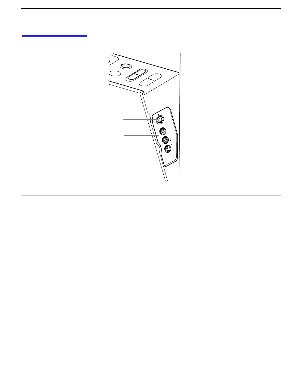
Side of Front Panel
M
E
N
U
TV
/V
ID
E
O
V
F
L
A
S
H
F
O
C
OL
U
M
E
C
U
+
S
–
H
AN
N
EL
+
–
qs
qd
S VIDEO
UT
P
IN
2
O
E
ID
V
VIDEO
(MONO)
L
AUDIO
R
qs S VIDEO 2 INPUT Connects to the S VIDEO OUT jack of your camcorder or other S VIDEO
equipped video component. Provides better picture quality than the
VHF/UHF jacks or the Video IN jack.
qd VIDEO 2 INPUT
VIDEO/L(MONO)-AUDIO-R
Connect to the audio and video OUT jacks on your camcorder or other video
component.
14
Page 25
Setting Up the Projection TV
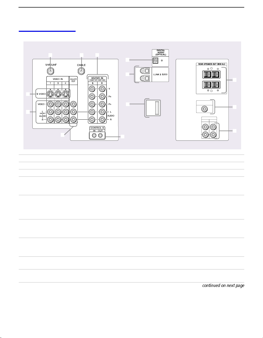
Rear Panel
DIGITAL
AUDIO
1
2
6
8
1
9
2
3
q;
4
5
7
Connection Description
1 VHF/UHF Connects to your VHF/UHF antenna. VHF/UHF is the digital TV antenna input.
2 CABLE Connects to your cable source.
3 S VIDEO IN 1/3/4 Connects to the S VIDEO OUT jack of your VCR or other S VIDEO-equipped
video component. Provides better picture quality than the VHF/UHF jacks or
the Video IN jack.
4 VIDEO IN 1/3/4
VIDEO/L(MONO)-AUDIO-R
Connect to the audio and video OUT jacks on your VCR or other video
component. A 6th video input (VIDEO 2) is located on the front panel of the
projection TV. The Audio and Video IN jacks provide better picture quality
than the VHF/UHF IN jack.
5 SELECT OUT Connect to the audio and video IN jacks on your VCR or other video
component. The output signal is determined by the SELECT OUT setting in the
Setup menu (see page 65).
6 HD/DVD IN
(1080i/720p/480p/480i)
Connect to your DVD player’s or digital set-top box’s component video (Y, P
R) and audio (L/R) jacks.
P
VIDEO IN 5/6
7 CONTROL S
IN/OUT
8 DIGITAL AUDIO (OPTICAL)
OUT PCM/DOLBY DIGITAL
Allows the projection TV to receive (IN) and send (OUT) remote control
signals to other Sony infrared-controlled audio or video components.
Connect to the optical audio input of an audio component that is Dolby Digital
and PCM compatible.
(OPTICAL)
OUT
PCM/DOLBY DIGITAL
L
R
SUB WOOFER
OUT
AUDIO OUT
FIX VAR
L
R
L
R
qa
qs
qd
B,
15
Page 26

Setting Up the Projection TV
Connection Description
9 i.LINK S200 Used for connecting i.LINK equipped devices.
0 Service Only For Sony service use only.
qa REAR SPEAKER OUT Used for connecting optional rear speakers.
qs SUBWOOFER OUT Used for connecting an optional powered subwoofer.
qd AUDIO OUT (VAR/FIX)
L(MONO)-AUDIO-R
Connect to the left and right audio inputs of your audio or video component.
16
Page 27
Basic Connections
Setting Up the Projection TV
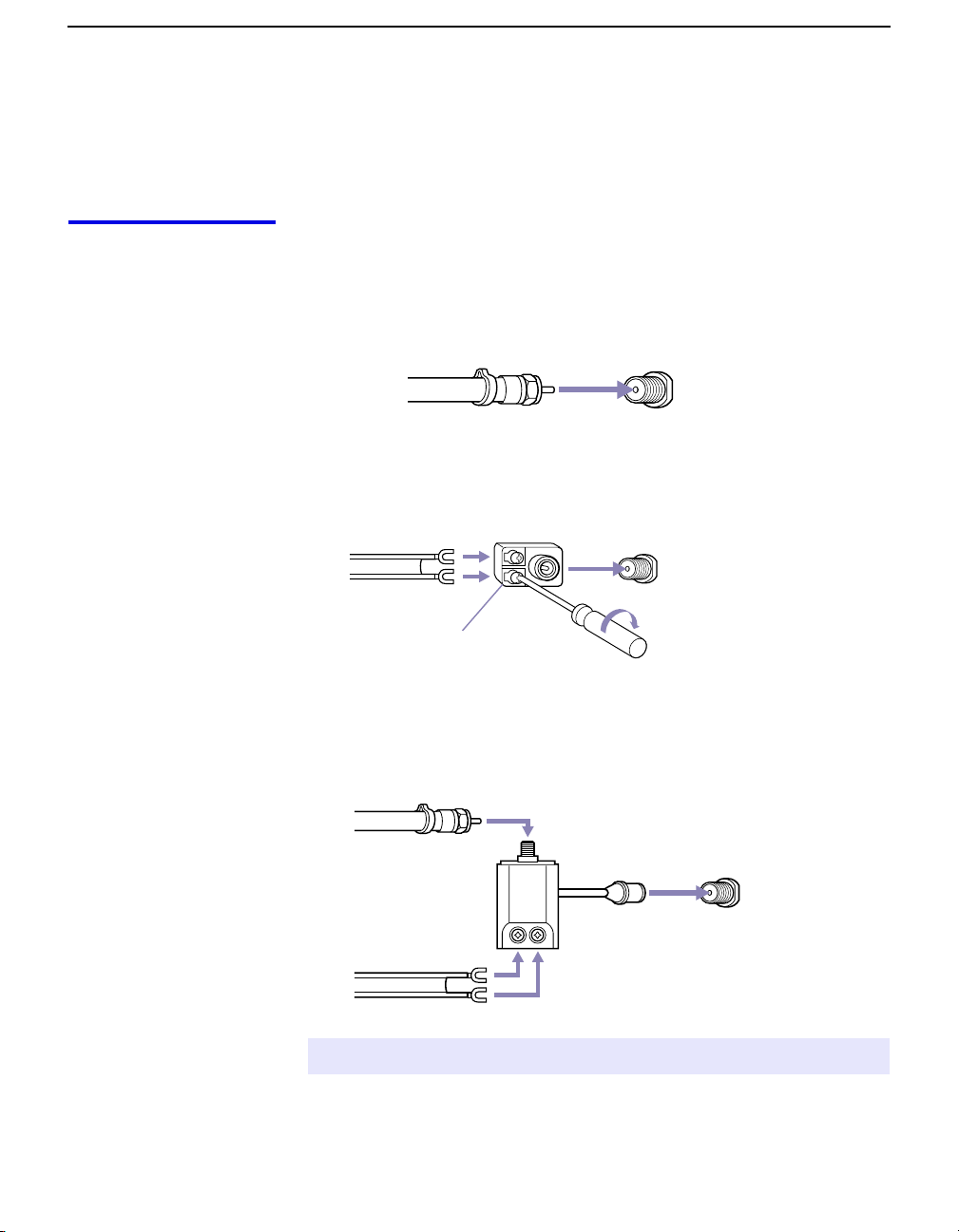
This section describes how to connect a VHF/UHF antenna, CATV
cable, and CATV cable box.
Connecting a
VHF/UHF Antenna
The connection you choose depends on the type of VHF/UHF
antenna you have in your home.
Newer homes are usually equipped with 75-ohm coaxial cable (A):
A VHF Only or VHF/UHF
75-ohm
coaxial
cable
VHF/UHF
Rear of TV
Older homes may have 300-ohm twin lead cable (B):
B VHF Only or UHF Only or VHF/UHF
300-ohm twin lead cable
Antenna connector
VHF/UHF
Rear of TV
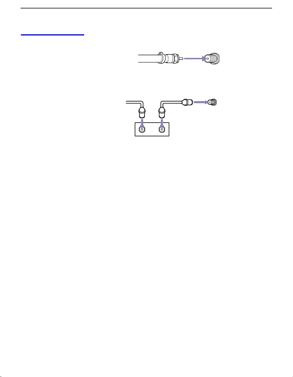
Some homes may have both 75-ohm coaxial and 300-ohm twin lead
cables (
C VHF and UHF
C):
75-ohm coaxial cable
VHF/UHF
Rear of TV
U/V Splitter
(not supplied)
300-ohm twin lead cable
✍ Of the three methods shown, connection A results in the best picture quality.
17
Page 28
Setting Up the Projection TV
Connecting a CATV
Cable or a
CATV Cable Box
CATV Cable
75-ohm
coaxial
cable
CATV Cable Box
Cable
IN
CABLE
Rear of TV
CABLE
Rear of TV
OUT
Cable Box
18
Page 29
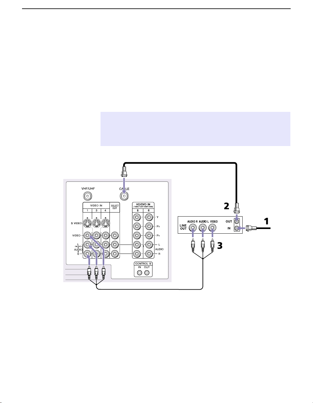
Connecting a VCR and Cable
Use this hookup if you have cable TV that does not require a cable
box.
1 Connect the cable TV cable to the VCR’s IN jack.
2 Using a coaxial cable, connect the VCR’s OUT jack to the
projection TV’s CABLE jack.
3 Using an A/V cable, connect the VCR’s Audio and Video OUT
jacks to the projection TV’s Audio and Video IN jacks.
✍ If the VCR you are connecting has an S VIDEO jack, you can use an S VIDEO
cable for improved picture quality (compared to a combination audio/video
cable). Because an S VIDEO cable carries only the video signal, you will also
need audio cables for sound.
Setting Up the Projection TV
AUDIO-R (red)
AUDIO-L (white)
VIDEO (yellow)
TV
Coaxial cable
VCR
Cable
A/V cable
19
Page 30

Setting Up the Projection TV
Connecting a VCR and Cable Box
Use this hookup if
❑
Your cable TV company scrambles some channels, but not all of
them (pay channels vs. regular cable channels), so you need to
use a cable box
❑ You want to use the Twin View or Scrolling Channel Index
feature.
With this setup you can
❑
Use the projection TV remote control to change channels using
your cable box when the signal is scrambled.
❑ Use the projection TV remote control to change channels using
your projection TV when the signal is not scrambled. (Your
projection TV’s tuner provides a better signal than the cable box.)
❑ Use the Twin View and Scrolling Channel Index features.
❑ Record both regular cable TV and scrambled channels.
To connect a cable box and a VCR, you will need
A small inexpensive device known as a splitter.
❑
❑ Three short coaxial cables.
❑ Either a combination audio/video cable, or an S VIDEO cable
and audio cables.
1 Connect the CATV cable to the single (input) jack of the splitter.
2 Use a coaxial cable to connect one of the two output jacks of the
splitter to the projection TV’s CABLE jack.
3 Use a coaxial cable to connect the other output jack of the splitter
to the input jack of the cable box.
4 Use a coaxial cable to connect the output jack of the cable box to
the input jack of the VCR.
5 Use the video line (yellow) of a combination audio/video (A/V)
cable to connect the video output jack of the VCR to the video
input jack of the projection TV.
✍ If your VCR has an S VIDEO jack, you can substitute an S VIDEO cable for
the video line of an A/V cable. The S VIDEO cable will provide improved
video signal quality.
6 Connect the left (white) and right (red) audio output channels of
the VCR to the respective input jacks on the projection TV.
20
Page 31

TV
A/V cable
VCR
Setting Up the Projection TV
Coaxial
Cable box
cable
Coaxial
cable
CATV
AUDIO-R (red)
AUDIO-L (white)
VIDEO (yellow)
Coaxial
cable
Splitter
(not included)
✍ IMPORTANT - To use the Twin View or Scrolling Channel Index feature or to
watch premium (scrambled) channels the VCR MUST BE TURNED ON;
otherwise, you will be unable to view them.
To view scrambled channels:
Press TV/VIDEO on the remote control to select the input to which
❑
you connected the VCR. Turn on the VCR, and make sure the
VCR input selection is set to RF Input. Then use the cable box to
change channels.
To prevent the accidental switching of channels:
❑
When using a VCR or cable box, you can use the Channel Fix
feature to lock in a channel. For details, see page 58.
21
Page 32

Setting Up the Projection TV
Connecting Two VCRs for Tape Editing
The SELECT OUT jacks allow you use a second VCR to record a
program being played by the primary VCR to edit and dub tapes.
1 Using an A/V cable, connect the playback VCR’s Audio and
Video OUT jacks to the projection TV’s Audio and Video IN
jacks.
2 Using an A/V cable, connect the recording VCR’s Audio and
Video IN jacks to the projection TV’s SELECT OUT jacks.
TV
VCR (recording)VCR (playback)
22
AUDIO-R (red)
AUDIO-L (white)
VIDEO (yellow)
A/V cable A/V cable
3 If necessary, change the video input on your VCR. (For details,
see your VCR’s instruction guide.)
To do tape editing
Press TV/VIDEO on the remote control to select the playback VCR.
❑
✍ You can select the output signal from the SELECT OUT jacks in the Setup menu.
For details, see page 65.
Page 33

Connecting a Satellite Receiver
1 Connect the satellite antenna cable to the satellite receiver’s
SATELLITE IN jack.
2 Using an A/V cable, connect the satellite receiver’s Audio and
Video OUT jacks to the projection TV’s Audio and Video IN
jacks.
3 Connect a coaxial cable from your cable or antenna to the
projection TV’s CABLE jack.
✍ If the receiver you are connecting has an S VIDEO jack, you can use an S VIDEO
cable for improved picture quality (compared to a combination audio/video
cable). Because S VIDEO cables carry only the video signal, you will also need
audio cables for sound.
TV
Setting Up the Projection TV
Coaxial
cable
AUDIO-R (red)
AUDIO-L (white)
VIDEO (yellow)
A/V cable
Satellite receiver
Satellite
antenna
cable
23
Page 34

Setting Up the Projection TV
Connecting a Satellite Receiver with a VCR
1 Connect the satellite antenna cable to the satellite receiver’s
SATELLITE IN jack.
2 Connect the CATV cable to the VCR’s VHF/UHF IN jack.
3 Using a coaxial cable, connect the VCR’s OUT jack to the
projection TV’s CABLE jack.
4 Using an A/V cable, connect the satellite receiver’s Audio and
Video OUT jacks to the VCR’s Audio and Video IN jacks.
5 Using an A/V cable, connect the VCR’s Audio and Video OUT
jacks to the projection TV’s Audio and Video IN jacks.
6 If necessary, change the video input on your VCR. (For details,
see your VCR’s instruction guide.)
AUDIO-R (red)
AUDIO-L (white)
VIDEO (yellow)
TV
Satellite
antenna
cable
Coaxial
cable
A/V cable
CATV
cable
Satellite receiver
VCR
✍ If the peripherals you are connecting have S VIDEO jacks, you can use S VIDEO
cables for improved picture quality (compared to combination audio/video
cables). Because S VIDEO cables carry only the video signal, you will also need
audio cables for sound.
24
Page 35

Connecting an Audio Receiver
For better sound quality, you may want to connect your projection TV
to your stereo system’s audio receiver.
To connect to an audio receiver
❑
Use audio cables to connect the projection TV’s Audio OUT jacks
to the audio receiver’s audio LINE IN jacks.
Setting Up the Projection TV
TV
L
R
SUB WOOFER
OUT
AUDIO OUT
FIX VAR
L
R
L
R
AUDIO-R AUDIO-L
(red) (white)
Line
input
25
Page 36

Setting Up the Projection TV
Connecting a DVD Player with Component
Video Connectors
This is the preferred hookup to use if your DVD player has
component video out jacks.
1 Using three separate component video cables, connect the DVD
player’s Y, P
projection TV. Use the HD/DVD IN 5 or 6 connections.
B and PR jacks to the Y, PB and PR jacks on the
✍ The Y, PB and PR jacks on your DVD player are sometimes labeled Y, CB and
R, or Y, B-Y and R-Y. If so, connect the cables to like colors.
C
2 Using an audio cable, connect the DVD player’s Audio OUT
jacks to the projection TV’s Audio IN jacks. Be sure to use the
same column of inputs that you used for the video connection
(HD/DVD IN 5 or 6).
Component video cables
TV
DVD player
AUDIO-R (red)
AUDIO-L (white)
Audio cable
✍ You cannot record the signal from any equipment connected into the Y, PB, PR
jacks.
26
Page 37

Connecting a DVD Player with A/V Connectors
Use this hookup if your DVD player does not have component video
out jacks (as shown on page 26).
✍ An S VIDEO connection will give a good-quality video signal, but if your DVD
player has component video, that connection (described on page 26) will give
an even better signal.
1 Using audio cables, connect the DVD player’s Audio OUT jacks
to the projection TV’s Audio IN jacks.
2 Using an S VIDEO cable, connect the DVD player’s S VIDEO jack
to the projection TV’s S VIDEO jack.
TV
S VIDEO
cable
Setting Up the Projection TV
DVD player
Audio cable
To switch between your projection TV, VCR and DVD
❑
Press TV/VIDEO to switch from one input device to another.
AUDIO-R (red)
AUDIO-L (white)
27
Page 38

Setting Up the Projection TV
Connecting a Camcorder
For easy connection of the camcorder, the projection TV has front
Audio and Video inputs (shown below). If you prefer, you can
connect the camcorder to the projection TV’s rear Audio and Video
IN jacks.
❑ Using A/V cables, connect the camcorder’s Audio and Video
OUT jacks to the projection TV’s Audio and Video IN jacks.
M
Inside the front panel
of the projection TV
EN
U
TV
/V
ID
E
O
V
F
LA
S
H
OL
U
ME
FO
C
U
S
+
–
+
–
C
H
AN
N
EL
Push to open
O
E
D
I
V
S
UT
P
IN
2
O
E
ID
V
VIDEO
(MONO)
L
AUDIO
R
28
Camcorder
If you have a mono camcorder, connect its audio output to the
projection TV’s AUDIO L jack.
✍ If the camcorder you are connecting has an S VIDEO jack, you can use an
S VIDEO cable for improved picture quality (compared to a combination
audio/video cable). Because S VIDEO cables carry only the video signal, you
will also need audio cables for sound.
Page 39

Setting Up the Projection TV
Connecting a Device with an Optical IN Connector
You can use the projection TV’s DIGITAL AUDIO OPTICAL
OUTPUT jack to connect an audio device that is Dolby Digital and
PCM compatible, such as an audio amplifier.
❑ Using an optical cable, connect the device’s DIGITAL AUDIO IN
jack to the projection TV’s DIGITAL AUDIO OPTICAL OUTPUT
jack.
E
LIN
T
U
O
IO
D
U
A
E
LIN
IN
OPTICAL
Audio amplifier
IN
Optical cable
TV
✍ The optical output works only for DTV programming, so you might also want to
connect the projection TV’s analog audio out connectors to the amplifier’s
analog audio in connectors, as described on page 25.
29
Page 40

Setting Up the Projection TV
Connecting i.LINK Compatible Devices
This projection TV is equipped with i.LINK, which provides a secure
digital interface to other digital home entertainment devices,
including digital cable set-top boxes. i.LINK allows for the secure
transfer of copyright-protected high-definition content between these
devices and your digital television.
✍ At the time this TV went to market, the Sony digital cable set-top box (DHG-
M55CV) is the only i.LINK device that is verified to be compatible with this TV.
Some early versions of the Sony digital cable set-top box (DHG-M55CV) may
not support an i.LINK digital connection to your TV. If you have difficulty with
the connection between your Sony digital cable set-top box (DHG-M55CV) and
your TV, contact Customer Information Service Center at 1-800-222SONY(7669). In most cases you can continue to use your set-top box with your
TV, using and analog audio/video connection (as shown on page 31), instead
of the i.LINK digital connection (also shown on page 31).
For more information about i.LINK, see “About i.LINK” on page 73.
Using i.LINK Cables This projection TV has two 4-pin S200 i.LINK terminals. You can use
any of the following i.LINK cables with the projection TV:
30
4-pin i.LINK cable
Sony Model Number Length
VMC-IL4415 1.5 meters
VMC-IL4435 3.5 meters
✍ Do not use cables other than the types listed above.
Page 41

Connecting Cables
TV
Setting Up the Projection TV
✍ Before connecting this unit to i.LINK-compatible equipment, see the instruction
manual of the i.LINK device to be connected.
1 Using an A/V cable, connect the i.LINK device’s Audio and
Video OUT jacks to the projection TV’s Audio and Video IN
jacks.
2 Using an i.LINK cable (see page 30), connect the device’s i.LINK
jack to either of the projection TV’s i.LINK jacks.
DIGITAL
AUDIO
(OPTICAL)
OUT
PCM/DOLBY DIGITAL
1
2
i.LINK cable
AUDIO-R (red)
AUDIO-L (white)
VIDEO (yellow)
Sony digital cable
set-top box
A/V cable
✍ i.LINK devices can be “hotplugged” (connected and disconnected while they
are still powered on). The projection TV automatically recognizes the device
and displays the screen shown on page 33.
31
Page 42

Setting Up the Projection TV
Notes on Connecting
i.LINK Devices
As additional compatible i.LINK devices are introduced in the future,
observe the following when connecting devices to the projection TV.
❑ To connect two or more i.LINK-capable devices, use i.LINK
cables to connect them as shown below.
A B C D E
i.LINK i.LINK i.LINK i.LINK
❑ You can connect up to 63 i.LINK devices. However, the
maximum number of cables in any serial route is 16.
A B C D
i.LINK i.LINK i.LINK i.LINK
E
F G
i.LINK i.LINK
❑ Do not connect i.LINK devices in a way that creates a loop.
i.LINK
32
A B C
i.LINK i.LINK
❑ Connecting non-compatible devices, such as camcorders, PCs, or
PC peripherals, may result in malfunctions.
Page 43

Setting Up the Projection TV
Completing i.LINK
Setup
Before you can use an i.LINK device with the projection TV, you need
to register the device as follows.
1 After you’ve connected the cables (as described on page 31), first
turn on the projection TV, and then turn on the i.LINK device(s).
The following screen automatically appears.
To add the i.LINK device, highlight
Add and press .
✍ If you select Cancel, the i.LINK device is set up as “hidden” and it does
not appear in the i.LINK Control Panel. To see the device in the i.LINK
Control Panel, change the i.LINK Setup option from Hide to Show in the
Setup menu (see page 65).
2 If you selected Add in step 1, and the device requires an analog
video connection (see the device’s instruction manual), the
following screen appears.
✍ Depending on the i.LINK device you are setting up, this screen may not be
displayed. In this case, the device’s video input will be displayed as N/A.
3 Move the joystick V and v to highlight the video input (VIDEO 1-4)
that connects the i.LINK device to the projection TV. If you don’t
need an analog video connection, select
A confirmation screen appears, which indicates the i.LINK device
name and video input. The device is now available in the i.LINK
Control Panel (see page 48).
For more information
❑
To change the setup of the i.LINK device, use the Setup menu.
For details, see page 65.
❑ For information on using the i.LINK Control Panel, see page 48.
❑ For general information about i.LINK, see page 73.
None. Then press .
33
Page 44

Setting Up the Projection TV
Using the CONTROL S Feature
CONTROL S allows you to control your system and other Sony
equipment with one remote control. In addition to allowing you to
control multiple devices with one remote control, the CONTROL S
feature allows you to always point your remote control at your
projection TV, instead of having to point it at the other equipment,
which might be hidden or out of direct line of sight.
Use CONTROL S IN to send signals to the projection TV.
Use CONTROL S OUT to send signals to connected equipment.
TV
34
Page 45

Setting Up the Projection TV Automatically
The first time you turn on the projection TV, a series of screens guide
you through the initial setup of the projection TV. During this setup,
you are prompted to set the clock and start Auto Program, which
z
The initial setup screens appear
only after turning on the projection
TV the first time, or after selecting
Factory Reset in the Setup menu
(page 66).
If you need to set the clock at a
later time, press the TIMER button
on the remote control (see
page 49).
You can also run Auto Program at
any time from the Channel Setup
menu (see page 58).
searches for and stores a list of analog and digital channels you are
receiving for VHF/UHF and CABLE inputs.
✍ Be sure to complete all connections before turning on the projection TV the
first time.
1 Press POWER to turn on the projection TV and display the Welcome
screen.
2 Press to continue Setup. The set clock screen appears.
3 Move the joystick V and v to set the current day and time (hour,
minute, and AM/PM). Press or move the joystick
each setting and move to the next setting. Move the joystick
go back to the previous setting.
Setting Up the Projection TV
b to confirm
B to
z
You can run the
demonstration again by
selecting Demo from the Setup
menu (see pages 64 to 66).
4 After you’ve set the clock, move the joystick b to highlight Next
and press to continue Setup. The Auto Program screen
appears.
5 To start Auto Program, press to select Auto Program. The
projection TV automatically creates a channel list of analog and
digital channels. (This may take a few minutes.)
6 When the channel list is complete, a Congratulations screen
appears.
To see a short demonstration of the features of the projection TV,
press to select
of the projection TV begins. To exit the demo at any time, press
any button on the remote control (or front panel).
To skip the demo and exit Setup, move the joystick
Done and press .
Demo. A self-running introduction to the features
b to highlight
35
Page 46

Setting Up the Projection TV
Adjusting the Convergence Automatically (Flash Focus)
The projection tube image appears on the screen in three colors (red,
green and blue). If they do not converge, the color is poor and the
picture blurs.
Before you use your projection TV, be sure to adjust the convergence.
The Flash Focus feature allows you to adjust the convergence
automatically.
✍ It is recommended that you perform Flash Focus about 30 minutes after the
projection TV is first turned on.
1 Tune to a TV or cable TV program.
2 Press FLASH FOCUS on the front panel of the projection TV (see
page 13).
The cross pattern appears and Flash Focus begins to work. The
adjustment is completed when the TV picture returns.
To Obtain Optimum
Convergence for
Digital TV Programs
,
The optimum convergence alignment varies with digital TV formats.
Whenever you find that the picture blurs, press
FLASH FOCUS.
✍ You cannot perform any other functions until Flash Focus has completed its
cycle. If you perform any other operation while Flash Focus is in progress, the
Flash Focus operation is canceled.
36
Page 47

Using the Projection TV Features
Overview
This chapter describes how to use features of your projection TV.
Topic Page
Using the Program Guide 38
Using the Scrolling Channel Index 39
Using Favorite Channels 40
Using Wide Screen Mode 43
Using Twin View 44
Using the Freeze Function 47
Using the i.LINK Control Panel 48
Using the Timer 49
37
Page 48

Using the Projection TV Features
Using the Program Guide
The Program Guide lets you select digital channels and subchannels
and review program information from an on-screen list. Subchannels
are additional channels of programming broadcast simultaneously.
For example, channel 4 might include five subchannels (4.1, 4.2, 4.3,
4.4, 4.5) that are showing programs at the same time.
✍ Analog channels are not available in the Guide.
1 Press GUIDE.
z
The Guide is not available
while using any of the
multipicture functions, such as
Twin View, Freeze, Scrolling
Channel Index, or Favorites.
z
As an alternative to using
the Guide you can select
subchannels directly using the
0-9 buttons and the button
on the remote control. For
example, to select channel 4.1,
press 4 + + 1 and then
ENTER.
The Program Guide appears, with the currently selected program
showing in the background.
✍ Program information in the Program Guide is provided by the broadcasters. As a
2 Move the joystick V and v to highlight the channel you want to
watch.The program on that channel appears in the background.
3 To remove the Program Guide and watch the highlighted
channel, press .
result, the Program Guide may sometimes include only the channel number
without a program title or description.
38
To exit the Program Guide without changing the channel
❑
Press EXIT or GUIDE.
Page 49

Using the Scrolling Channel Index
The Scrolling Channel Index lets you select programs from a scrolling
index of video pictures.
1 Press INDEX.
The Scrolling Channel Index appears, with the currently selected
program in the main (left) window, and four scrolling video
pictures in the right.
As each picture on the right scrolls to the live preview window, it
changes briefly from a frozen video picture to a live video. The
right side continues to scroll through the entire channel list.
2 To change the direction of the scrolling, move the joystick V or v.
Using the Projection TV Features
Live preview
window
3 To change the speed of the scrolling, move and hold the joystick
V or v.
4 To change a frozen video picture to a live video, move the
joystick V or v to highlight the picture, then press .
5 To move the live video (from step 4) from the right to the main
(left) window of the Scrolling Channel Index, press again.
To exit the Scrolling Channel Index
❑
Press EXIT or INDEX.
39
Page 50

Using the Projection TV Features
Using Favorite Channels
You can store up to 16 of your favorite channels in the Favorite
Channels list. You can use the Surf Favorites feature to preview and
select channels directly from the list. You can also edit the Favorite
Channels list to change the channels that are included in the list.
Adding Favorite
Channels
1 Tune to the channel you want to save to the Favorite Channels list
and press
A message appears, indicating that the channel was stored in the
Favorite Channels list.
ADD.
2 To add more channels (to a total of 16), repeat step 1.
If you try to add more than 16 channels to the Favorite Channels list
A message appears, indicating that the Favorite Channels list is full.
To change the Favorite Channels list, select
Favorite Channels List” on page 42). Or to cancel storing the channel,
Cancel.
select
If you try to add a digital subchannel to the Favorite Channels list
Only the major channel number is saved as a Favorite Channel. For
example, if you are watching channel 51.4 and you press
channel 51 is saved as a Favorite Channel. Then, when you surf to
Favorite Channel 51, the projection TV tunes to channel 51 or the first
available digital subchannel it finds (channel 51.1, 51.2, etc).
Edit (then see “Editing the
ADD, only
40
Page 51

Using the Projection TV Features
Surfing the Favorite
Channels List
z
The letter “C” indicates that
the Favorite Channel is a cable
channel.
1 Press SURF.
The Surf Favorites screen appears, with the currently selected
program in the main (left) window.
Main
Window
C8
10
18
C5
22
C11
2
5
Preview
Window
Favorite
Channels
2 To see a preview of a program on your Favorite Channels, move
the joystick V or v through the Surf Favorites list. A preview of
the highlighted channel, when available, appears in the preview
window.
✍ Digital channels are displayed as a black box in the preview window.
If more than eight Favorite Channels are set, indicated by scroll
arrows (V v), move the joystick V or v to see the additional
Favorite Channels.
3 To remove the Surf Favorites list and watch the highlighted
channel, press .
To exit the Surf Favorites list without changing the channel
❑
Press EXIT or SURF.
41
Page 52

Using the Projection TV Features
Editing the Favorite
Channels List
z
The letter “C” indicates
that the Favorite Channel is a
cable channel.
1 Press MENU.
2 Move the joystick to highlight the Channel Setup icon and
press .
3 Move the joystick to highlight Favorite Channels and press .
The Favorite Channels list appears.
If more than nine Favorite Channels are set, move the joystick V
or v to see the other Favorite Channels.
4 To select a Favorite (1-16) to edit, move the joystick V or v to
highlight the number and press .
5 Move the joystick V or v to scroll through the channel list. A
preview of the highlighted channel, when available, appears in
the preview window.
42
✍ Digital channels are displayed as a black box in the preview window.
6 To set the channel to the Favorite Channel list, press .
To set additional channels (to a total of 16)
❑
Repeat steps 4 to 6.
To clear a Favorite Channel from the list
❑
After step 4, press the RESET button on the remote control.
To exit the Edit Favorites list
Press EXIT.
❑
Page 53

Using Wide Screen Mode
Wide Screen mode lets you watch 4:3 normal broadcasts in several
Wide Screen modes (16:9 aspect ratio).
z
You can also access the
Wide Mode settings in the
Screen Mode menu. For details,
see page 56.
z
When you change channels
or inputs, the Wide Mode
settings revert to Wide Zoom (or
the 4:3 Default setting in the
Screen Mode menu). To retain
the current Wide Mode setting
as channels and inputs are
changed, set 4:3 Default to Off.
For details, see page 57.
❑ Press WIDE MODE repeatedly to toggle through the following Wide
Mode settings.
Using the Projection TV Features
Wide Zoom enlarges the 4:3
picture, while the upper and
lower parts of the picture are
condensed to fit the 16:9 screen.
Wide Zoom
m
Normal returns the 4:3 picture to
its original size.
Normal
m
Full Mode stretches the 4:3
picture horizontally only, to fill
the 16:9 screen.
Full
m
Zoom
Zoom Mode enlarges the 4:3
picture horizontally and
vertically to an equal aspect ratio
that fills the 16:9 screen. Useful
for watching Letterbox movies.
43
Page 54

Using the Projection TV Features
Using Twin View
Twin View lets you see two pictures from two sources — from an
antenna, VCR, DVD, etc., — on the screen at the same time. (You hear
the sound from only one of the sources at a time. You choose which
source’s sound is selected.) You can change the relative size of each of
the pictures.
Displaying Twin
Pictures
1 Tune the projection TV to a working channel.
2 Press .
A second picture-window appears.
,
,
To cancel twin pictures and watch the active picture
❑
Press or .
44
Page 55

Using the Projection TV Features
Activating the
Picture
With Twin View, the picture highlighted in blue is active. In the active
picture, you can:
❑ Change channels.
❑ Adjust the volume.
❑ Switch the input sources (to go from UHF/VHF to cable, for
example, press
❑ Change the picture size by moving the joystick V or v.
To activate the right picture
❑
Move the joystick b.
ANT or TV/VIDEO on the remote control).
To activate the left picture
❑
Move the joystick B.
,
,
Factors affecting Twin View include
❑
If you use a cable box to view all channels, the same channel
appears in both windows of Twin View because the cable box
unscrambles only one channel at a time.
❑ If you use a cable box, you can view the cable box output in one
Twin View window and view a signal from a different source
(such as a VCR or DVD player) in the second window.
❑ Digital channels and equipment connected to VIDEO 5 or VIDEO
6 inputs display in the left Twin View window only, but not the
right.
❑ If you are viewing a 4:3 source and a 16:9 enhanced source (such
as a DVD) side by side in Twin View, the 4:3 source will appear
larger.
❑ Twin View is not available while viewing i.LINK devices.
45
Page 56

Using the Projection TV Features
Changing the
Picture Size
The zoom feature lets you vary the relative size of the left and right
pictures.
1 Activate the picture whose size
you want to change.
2 Move the joystick V to enlarge
the picture.
3 Move the joystick v to make the
picture smaller.
46
When you adjust the twin screen sizes, the projection TV memorizes
the change. The next time you use the Twin View function, the
memorized sizes appear.
Page 57

Using the Freeze Function
The FREEZE button allows you to temporarily capture a program’s
picture. You can use this feature to write down information such as
phone numbers, recipes, etc.
✍ The Freeze feature is not available while using Twin View.
1 When the program information you want to capture is displayed,
press the
2 The projection TV switches to Twin View mode and displays the
“frozen” picture on the right, while the current program
continues on the left.
Using the Projection TV Features
FREEZE button.
Current program
in progress
Call 555-1234
Frozen
picture
3 To cancel and return to normal viewing, press the FREEZE or EXIT
button.
47
Page 58

Using the Projection TV Features
Using the i.LINK Control Panel
The i.LINK Control Panel lets you see a list of i.LINK devices that are
connected to and communicating with the projection TV.
✍ At the time this TV went to market, the Sony digital cable set-top box (DHG-
M55CV) is the only i.LINK device that is verified to be compatible with this TV.
Some early versions of the Sony digital cable set-top box (DHG-M55CV) may
not support an i.LINK digital connection to your TV. If you have difficulty with
the connection between your Sony digital cable set-top box (DHG-M55CV) and
your TV, contact Customer Information Service Center at 1-800-222SONY(7669). In most cases you can continue to use your set-top box with your
TV, using and analog audio/video connection (as shown on page 31), instead
z
You can also access the
i.LINK Control Panel using the
the button on the projection
TV’s front panel. For details, see
page 13.
of the i.LINK digital connection (also shown on page 31).
1 To display the i.LINK Control Panel, press the button.
The i.LINK Control Panel appears, which displays a list of i.LINK
devices that are set to Show in the i.LINK Setup menu (page 65).
48
✍ If the i.LINK device is not listed in the i.LINK Control Panel, you need to
change the i.LINK Setup option from Hide to Show (see page 65).
The projection TV is always the first device listed. If other i.LINK
devices are connected, they are listed according to their
manufacturer’s model name. If there are duplicate models
connected, they are also designated a number (1,2,3, etc.). If a
device is unknown, it is listed as “Device.”
If no i.LINK devices are connected to the projection TV, the
message “There are no i.LINK devices available” is displayed.
2 To check the status of an i.LINK device, move the joystick V or v
to highlight the device name. The background continues to
display the video of the device that is selected.
3 To select a new i.LINK device and change the background video
to that device, press .
4 To exit the i.LINK Control Panel and return to normal viewing,
press the button (or
EXIT).
Page 59

Using the Timer
You can use the Timer to program the projection TV to turn on and off
and tune to a specific channel at two scheduled viewing times.
The first time you turned on the projection TV, a setup screen
prompted you to set the clock (see “Setting Up the Projection TV
Automatically” on page 35). If you didn’t set the clock during this
initial setup, you need to set it before you can use the Timer (see
page 50).
Setting the Timer 1 Press TIMER.
Using the Projection TV Features
z
You can also access the
Timer through the Setup menu.
For details, see page 66.
The Set Clock/Timers screen appears, with the current timer
settings shown.
2 To set the Timer, move the joystick V or v to highlight Timer 1 or
Timer 2, then press .
✍ The clock must be set before you can set either of the Timers. If the clock
is not set, Timer 1 and Timer 2 cannot be selected. To set the clock, see
“Setting the Clock” on page 50.
3 Move the joystick V or v to highlight one of the following
options
Set Select to set or change the timer settings for the selected
On Select to turn on the timer settings for the selected Timer
Off Select to turn off the timer settings for the selected Timer
, then press .
Timer (Timer 1 or Timer 2).
(Timer 1 or Timer 2).
(Timer 1 or Timer 2).
4 If you selected Set in step 3, the setup screen for the selected Timer
Timer 1 or Timer 2) appears.
(
49
Page 60

Using the Projection TV Features
5 Move the joystick V and v to set the day(s), time (hour, minute,
6 After you’ve set the channel number, press to save the Timer
The projection TV is now set to turn on, tune to the channel you’ve
set, and then turn off at the times you set for that Timer. The Timer
indicator on the front panel indicates the Timer is set.
To turn a Timer setting on or off
❑
To change a Timer setting
❑
To set a second Timer setting
❑
AM/PM), duration, and channel number. Press or
confirm each setting and move to the next setting. Press
back to the previous setting.
settings. The settings are displayed in the Timer screen and the
Timer is set to
Select On or Off in step 3 (page 49).
Set the timer (Timer 1 or Timer 2) again. The old timer setting is
overwritten.
Set the other unset timer (Timer 1 or Timer 2).
On.
b to
B to go
Setting the Clock If you didn’t set the clock during the projection TV’s initial setup (see
page 35), you need to set it before you can set either of the Timers.
z
You can also access the
Timer through the Setup menu.
For details, see page 66.
1 Press TIMER.
The Timer Setup screen appears (as shown on page 49).
2 Move the joystick V or v to highlight Set the Clock, then press .
3 Move the joystick V and v to set the current day and time (hour,
minute, and AM/PM). Press or move the joystick
each setting and move to the next setting. Move the joystick
go back to the previous setting.
b to confirm
B to
4 When you finish setting the day and time, press to save the
clock settings.
50
Page 61

Using the Projection TV Menus
Overview
To open and choose a menu
1 Press MENU to display the menu screen.
2 Move the joystick V or v to highlight the icon of the menu you
want to select and press .
3 Move the joystick V or v to scroll through the options.
4 See the specific menu page for instructions on moving through
the menu.
The Menu gives you access to the following features:
Menu Icon Description Page
The Video menu allows you to make adjustments to
your picture settings, lets you customize the Picture
Mode based on the type of program you are viewing,
and more.
The Audio menu offers enhanced audio options such
as listening to second audio programming (SAP),
customizing the Effect of the sound on your
To end a menu session
Press EXIT.
To move from one menu to
another
Move the joystick B to
return to the menu icons.
Move the joystick V or v
to choose the next menu
icon and press to
select it.
projection TV, and more.
The Screen Mode menu allows you to make Wide
Mode adjustments and make changes to the screen’s
vertical center.
The Channel Setup menu allows you to edit your
Favorite Channels list, run the Auto Program
function, and more.
The Parental Control menu lets you control the
viewing of programs based on their ratings.
52
54
56
58
60
The Setup menu provides options for setting up
your system, including selecting closed caption
modes, setting the Timer, labeling Video inputs,
changing the status of i.LINK devices, selecting the
language of the on-screen menus, and more.
64
51
Page 62

Using the Projection TV Menus
Using the Video Menu
To select the Video menu
1 Press MENU.
2 Move the joystick V or v to highlight
the Video icon and press .
3 Move the joystick V or v to scroll
through the features.
4 Press to select a feature. That
feature’s adjustment appears.
5 Use the joystick to make the desired adjustments.
6 Press to select/set.
7 Press EXIT to exit the menu screen.
To restore the factory default settings for Picture, Brightness, Color, Hue, and
Sharpness, Color Temp
❑ Press RESET on the remote control when in the Video menu.
The factory default settings are restored only for the Picture Mode
that is currently selected.
Selecting Video
Options
z
To change from one Video
Mode to another, use the PIC
MODE button on the remote
control.
z
You can customize each
Picture Mode (Vivid, Standard,
Movie, etc.) by changing the
other video menu options
(Picture, Brightness, Color, etc).
52
The Video menu includes the following options.
Option Description
Picture Mode
Preset picture
viewing
modes
Picture Adjust to increase picture contrast and deepen the color or
Brightness Adjust to brighten or darken the picture.
Vivid Select for enhanced picture contrast and
sharpness.
Standard Recommended for Normal viewing
conditions.
Movie Select to display a finely detailed picture for
low-light environments.
Game Select to reduce the visibility of artifacts,
which often appear in graphics and
animation (such as in a video game). Game
can also be used to improve the picture
quality on channels with noisy or poor signal
reception.
Pro Select to display a picture with minimum
enhancements.
decrease picture contrast and soften the color.
Page 63

z
To change from one DRC
Mode to another, use the DRC
button on the remote control.
Using the Projection TV Menus
Option Description
Color Adjust to increase or decrease color intensity.
Hue Adjust to increase or decrease the green tones.
Sharpness Adjust to sharpen or soften the picture.
Color
Temperature
White
intensity
adjustment
DRC Mode
Digital
Reality
Creation
Alternate
Video
Choose from three color temperatures:
Cool Select to give the white colors a blue tint.
Neutral Select to give the white colors a neutral tint.
Warm Select to give the white colors a red tint
(NTSC-Standard).
Creates a high-resolution picture with 4x density, for high
quality sources (i.e., DVD player, satellite receiver).
Interlaced Recommended for moving pictures.
Progressive Recommended for still images and text.
CineMotion Provides an optimized display by
automatically detecting film content and
applying a reverse 3/2 pulldown process.
Moving pictures will appear clearer and
more natural-looking.
Allows you to select from the available video streams for the
current program. (For example, a sporting event that
broadcasts multiple video streams.)
To select an alternate video source, move the joystick V or v
to select an alternate video option and press . (Unavailable
when alternate video streams are not broadcast.)
53
Page 64

Using the Projection TV Menus
e
Using the Audio Menu
To select the Audio menu
1 Press MENU.
2 Move the joystick V or v to highlight
the Audio icon and press .
3 Move the joystick V or v to scroll
through the options.
4 Press to select an option. That
option’s settings appear.
5 Use the joystick to scroll through the settings.
6 Press to select the desired setting.
7 Press EXIT to exit the menu screen.
To restore the factory default settings for Treble, Bass, and Balance
❑
Press RESET on the remote control when in the Audio menu.
Selecting Audio
Options
z
To change from one Effect to
another, use the button on th
inside panel of the remote
control.
z
To change from one MTS
Mode to another, use the
MTS/SAP button on the remote
control.
The Audio menu includes the following options:
Option Description
Tre bl e Adjust to increase or decrease higher-pitched sounds.
Bass Adjust to increase or decrease lower-pitched sounds.
Balance Adjust to emphasize left or right speaker balance.
Effect Dolby
Surround
Simulated Adds a surround-like effect to mono
OFF Normal stereo or mono reception.
MTS
Enjoy stereo,
bilingual and
mono programs
Stereo Select for stereo reception when viewing a
Auto SAP Select to automatically switch the projection
Mono Select for mono reception. (Use to reduce
Select for surround sound (for stereo
programs only).
programs (requires optional rear speakers).
program broadcast in stereo.
TV to second audio programs when a signal
is received. (If no SAP signal is present, the
projection TV remains in Stereo mode.)
noise during weak stereo broadcasts.)
54
Page 65

z
No test tone is output from
the subwoofer.
Using the Projection TV Menus
Option Description
Speaker Setup Speaker Select to control which of the projection TV’s
speakers are active. Select from
Front/Center/Rear, Front/Center, and Off.
Subwoofer Select whether you are using a powered
subwoofer (Yes) or not (No).
Tes t Ton e You can use the test tone to compare the
speaker output levels. Use Center Level/Rear
Level and Front Balance/Rear Balance to adjust
the levels while the test tone is on. When you
select On, a test tone is output from each
speaker, as follows:
If Speaker is set to Front/Center/Rear:
Left t Center t Right t Right Rear t Left Rear
If Speaker is set to Front/Center:
Left t Center t Right
To turn off the test tone, press MENU or EXIT.
(Available only when Effect is set to Dolby
Surround and Speaker is set to Front/Center/Rear or
Fro nt/Center.)
Center Level Select to adjust the relative volume level of
the center speakers. (Available only when
Effect is set to Dolby Surround and Speaker is set
to Front/Center/Rear or Front/Ce nter.)
Rear Level Select to adjust the relative volume level of
the rear speakers. (Unavailable if Speaker is set
to Off or Front/Center.)
Front
Balance
Rear Balance Select to adjust the left to right balance of the
Subwoofer
Level
Alternate Audio Cycles through the available audio tracks for the current
program. (For example, a sporting event that broadcasts
multiple commentators.)
Select to adjust the left to right balance of the
front speakers. (Unavailable if Speaker is set to
Off.)
rear speakers. (Unavailable if Speaker is set to
Off or Front/Center.)
Select to adjust the relative volume level of
the subwoofers. (Unavailable if Speaker or
Subwoofer is set to No.)
55
Page 66

Using the Projection TV Menus
Using the Screen Mode Menu
To select the Screen Mode menu
1 Press MENU.
2 Move the joystick V or v to highlight
the Screen Mode icon and press .
3 Move the joystick V or v to scroll
through the features.
4 Press to select a feature. That
feature’s options appear.
5 Use the joystick to scroll through the options.
6 Press to select the desired option.
7 Press EXIT to exit the menu screen.
Selecting Screen
Mode Options
z
To change from one Wide
Mode to another, use the WIDE
MODE button on the remote
control.
The Screen Mode menu includes the following options:
Option Description
Wide Mode
Select a Wide
Mode to use for
4:3 sources.
Wide Zoom Select to enlarge the 4:3 size picture, while
the upper and lower parts of the picture are
condensed to fit the wide screen.
Normal Select to return the 4:3 picture to normal
mode.
Full Select to enlarge the 4:3 picture
horizontally only, to fill the wide screen.
Zoom Select to enlarge the 4:3 picture
horizontally and vertically to an equal
aspect ratio that fills the wide screen.
(Wide Mode is unavailable while in Twin View.)
56
Page 67

z
If 4:3 Default is set to
anything but Off, the Wide Mode
setting changes only for the
current channel. When you
change channels (or inputs),
Wide Mode is automatically
replaced with the 4:3 Default
setting. To retain the current
Wide Mode setting as channels
and inputs are changed, set 4:3
Default to Off.
Using the Projection TV Menus
Option Description
4:3 Default
Select the default
Screen Mode to
use for 4:3 sources.
Vertical Center Allows you to move the position of the picture up and
Wide Zoom Select to enlarge the 4:3 size picture, while
the upper and lower parts of the picture are
condensed to fit the wide screen.
Normal Select to return the 4:3 picture to normal
mode.
Full Select to enlarge the 4:3 picture
horizontally only, to fill the wide screen.
Zoom Select to enlarge the 4:3 picture
horizontally and vertically to an equal
aspect ratio that fills the wide screen.
Off Select to continue using the current Wide
Mode setting when the channel or input is
changed.
down in the window. (Available only in Wide Zoom and
Zoom modes.)
Move the joystick V or v to choose a position and press
.
57
Page 68

Using the Projection TV Menus
Using the Channel Setup Menu
To select the Channel Setup menu
1 Press MENU.
2 Move the joystick V or v to highlight
the Channel Setup icon and press
.
3 Move the joystick V or v to scroll
through the features.
4 Press to select a feature. That
feature’s options appear.
5 Use the joystick to scroll through the options.
6 Press to select the desired option.
7 Press EXIT to exit the menu screen.
Selecting Channel
Setup Options
The Channel Setup menu includes the following options:
Option Description
Favorite Channels Edit Select to edit the Favorite Channels list. For
details, see “Editing the Favorite Channels
List” on page 42.
Channel Fix
Useful when you
have a cable box or
satellite receiver
connected
Auto Program Automatically programs the projection TV for all
Off Turns o ff Channel Fix.
VIDEO 1 Use this setting if you have connected the
device to the Audio and Video IN jacks.
2-6 “Fix” your projection TV’s channel setting
to channels 2-6 and use the cable box, VCR
or satellite receiver to change channels.
Select one of these settings if you connected
the device to the VHF/UHF jack.
Cable 2-6 Same as 2-6, except you select one of these
settings if you connected the device to the
CABLE jack.
receivable channels.
Find and
Overwrite
DTV Auto Add Select to automatically add new digital
Select to automatically program the
projection TV for all receivable channels for
the selected input (Cable or VHF/UHF).
channels to the digital channel list.
(Available only for UHF/VHF input.)
58
Page 69

Using the Projection TV Menus
Option Description
Channel
Skip/Add
Allows you to customize the channel list that appears
when using the CH+/- buttons on the remote control. The
projection TV maintains separate channel lists for digital
and analog channels.
Digital Select to add or skip digital channels.
Analog Select to add or skip analog channels.
1 Move the joystick V or v to scroll through the
channels until you find the channel you want to
skip/add.
2 Press to select it.
3 Move the joystick V or v to toggle between Add
Skip. Then press to select.
and
4 Move the joystick B to return to the Channel
Setup menu, or press
Channel Logo Allows you to assign logos to channel numbers.
Channel List Select to display the channel list.
To assign a logo for a channel number:
EXIT to exit the menus.
1 Move the joystick V or v to highlight the
channel number to which you want to assign a
logo. Then press to select that channel
number.
Digital Signal
Strength
2 Move the joystick B bVv to highlight one of the
logos. Then press to assign that logo to the
selected channel number.
3 Move the joystick B to return to the Channel
Setup menu, or press
Displays the strength of the terrestrial digital broadcast
signal, to help you adjust your antenna to optimize signal
reception. When the TV is receiving a good signal (the
signal is locked and there are no errors in the signal), the
green light appears. Adjust the antenna
until the green light appears.
EXIT to exit the menus.
59
Page 70

Using the Projection TV Menus
Using the Parental Control Menu
The Parental Control menu allows you to set up the projection TV to
block programs according to their content and rating levels. These
ratings are assigned by a federal rating board. Not all programs are
rated. Using the Parental Lock blocks programs with a specific rating,
but it does not block an entire channel.
To select the Parental Control menu
1 Press MENU.
2 Move the joystick V or v to highlight
the Parental Control icon and press
.
3 Use the 0-9 buttons on the remote
control to enter your four-digit
password.
4 If this is your first time setting a password, confirm your
password by entering it again. (The Parental Control menu
options appear.)
5 Move the joystick V or v to scroll through the settings.
6 Press to select the desired option.
7 Press EXIT to exit the menu screen.
✍ You need your password for any future access into the Parental Control
menu. If you lose your password, see “Lost password” on page 75.
60
Page 71

Using the Projection TV Menus
Using the Parent
Menu
z
If you are not familiar with
the Parental Guideline rating
system, you should select Child,
Youth, or Young Adult to help
simplify the rating selection. To
set more restrictive ratings,
select Custom.
The Parent menu includes the following options.
Option Description
Parenta l Lock
Turn ratings
on/off and select a
rating system
Change Password For changing your password.
Select Country USA Select to use USA ratings (see page 62).
Off Parental lock is off. No programs are
blocked from viewing.
Child Maximum ratings permitted are:
❏ US: TV-Y, TV-G, G
❏ Canada: TV-Y, C, G
Youth Maximum ratings permitted are:
❏ US: TV-PG, PG
❏ Canada: TV-PG, PG, 8 ans+
Young Adult Maximum ratings permitted are:
❏ US: TV-14, PG-13
❏ Canada: TV-14, 14+, 13 ans+
Custom Select to set ratings manually.
❏ US: See page 62 for details.
❏ Canada: See page 63 for details.
Canada Select to use Canadian ratings (see
page 63).
61
Page 72

Using the Projection TV Menus
United States:
Selecting Custom
Rating Options
z
To ensure maximum
blocking capability, the agebased ratings should be
blocked.
z
The content ratings will
increase depending on the
level of the age-based rating.
For example, a program with a
TV-PG V (Violence) rating may
contain moderate violence,
while a TV-14 V (Violence)
rating may contain more
intense violence.
z
If you block unrated TV
programs, be aware that the
following types of programs
may be blocked: emergency
broadcasts, political programs,
sports, news, public service
announcements, religious
programs and weather.
For the United States, the Custom Rating Menu includes the
following options. (For Canada, see page 63.)
Option Description
Movie Rating G All children and General Audience.
PG Parental Guidance suggested.
PG-13 Parental Guidance for children under 13.
R Restricted viewing, parental guidance is
suggested for children under 17.
TV Rating
Block programs
by their rating,
content or both
Unrated
Block programs
or movies that
are broadcast
without a rating
NC-17
and X
Age-Based Options
TV-Y All children.
TV-Y7 Directed to children age 7 and above.
TV-G General Audience.
TV-PG Parental Guidance suggested.
TV-14 Parents Strongly cautioned.
TV-MA Mature Audience only.
Content-Based Options
FV Fantasy Violence.
D Suggestive Dialogue.
L Strong Language.
S Sexual situations.
V Violenc e.
Block Blocks all programs and movies that are
Allow Allows programs and movies that are
No one 17 and under allowed.
broadcast without a rating.
broadcast without a rating.
62
Page 73

Using the Projection TV Menus
Canada:
Selecting Custom
Rating Options
Viewing Blocked
Programs
For Canada, the Custom Rating Menu includes the following options.
(For the US, see page 62.)
Option Description
English Rating C All children.
C8+ Children 8 years and older.
G General programming.
PG Parental Guidance.
14+ Viewers 14 and older.
18+ Adult programming.
French Rating G General programming.
8 ans+ Not recommended for young children.
13 ans+ Not recommended for ages under 13.
16 ans+ Not recommended for ages under 16.
18 ans+ Programming restricted to adults.
USA TV Rating See page 62 for details.
You can view a blocked program by pressing the ENTER button when
tuned to a blocked program. Entering the correct password
temporarily switches off the Parental Lock. To reactivate the Parental
Lock settings, turn off the projection TV. When the projection TV is
turned on again, your Parental Controls settings are reactivated.
63
Page 74

Using the Projection TV Menus
Using the Setup Menu
To select the Setup menu
1 Press MENU.
2 Move the joystick V or v to highlight
the Setup icon and press .
3 Move the joystick V or v to scroll
through the features.
4 Press to select a feature. (That
feature’s options appear.)
5 Move the joystick V or v to scroll through the options.
6 Press to select the desired option.
7 Press EXIT to exit the menu screen.
Selecting
Setup Options
The Setup Menu includes the following options:
Option Description
Caption Vision Allows you to select from three caption modes (for
programs that are broadcast with closed caption).
CC1, CC2,
CC3, CC4
TEXT1, TEXT2,
TEXT3, TEXT4
Info Banner Displays the program name and the time
Off Turns off Caption Vision.
Displays a printed version of the dialog or
sound effects of a program. (Should be set to
CC1 for most programs.)
Displays network/station information
presented using either half or the whole
screen (if available). For closed captioning,
set to CC1.
remaining in the program (if the broadcaster
offers this service). Displays when the
channel is changed or the DISPLAY button is
pressed.
64
Page 75

z
You can also use the
Video Input option to assign
video inputs to i.LINK devices.
When you select that video
input, an i.LINK connection is
established. Only i.LINK
devices that are set to Show
(see “i.LINK Setup”) and
which support video input
connection are listed.
Using the Projection TV Menus
Option Description
Select Out Allows you to select which input to pass through to the
equipment connected to the SELECT OUT jacks on the
DTV.
Monitor Outputs the picture displayed on the screen.
TV Outputs the signal that the TV is tuned to
(regardless of the picture displayed on the
screen).
VIDEO 1-4 Outputs the signal input to the TV
(regardless of the picture displayed on the
screen).
Video Input Allows you to select labels to help you recognize devices
connected to the audio/video jacks on the DTV. For
example, if you have a DVD player connected to the
VIDEO 2 jack, you can select the label DVD for the VIDEO 2
input.
To select a label for a video input:
1 Move the joystick V or v to highlight the video
input (VIDEO 1-6) that you want to assign a
label. Then press to select the input.
2 Move the joystick V or v to highlight one of the
displayed labels. Then press to select it.
z
For details about using
the i.LINK Control Panel, see
page 48.
If you select the label Skip, your DTV skips this connection
when you press the TV/VIDEO button. i.LINK devices
cannot be assigned to VIDEO 5 or 6.
Language Select to display all on-screen menus in your language of
choice (English, Espanol, Francais).
i.LINK Setup Select to display a list of i.LINK devices that are connected
to the DTV. To change the status of an i.LINK device:
1 Move the joystick V or v to highlight an i.LINK
device. Then press to select the device.
2 Move the joystick V or v to highlight one of the
following options. Then press to select it.
Show Select to display this device in the i.LINK
Control Panel.
Hide Select to not display this device in the
i.LINK Control Panel. This is for devices that
are connected to, but not communicating
with, the DTV (or for devices that you don’t
want to appear in the i.LINK Control Panel).
Delete Select for i.LINK devices that you have
disconnected from the DTV. To reconnect the
device, see page 30.
65
Page 76

Using the Projection TV Menus
r
z
For details about power
consumption in standby
modes, see page 78.
z
You can also access the Time
using the TIMER button on the
remote control.
Option Description
i.LINK Standby
Allows you to
manage standby
power
consumption
Set Clock/Timers Select to set the clock and to program your DTV to turn on
Demo Runs a demonstration of the features of the DTV.
Factory Reset Restores all menu options to their original factory settings.
On Allows the i.LINK signal to pass through to
connected i.LINK devices even when the
projection TV is turned off. Front panel LED
is orange. The projection TV uses more
standby power than when this option is set
to Off.
Off Does not allow the i.LINK signal to pass
through to connected i.LINK devices when
the projection TV is turned off. Front panel
LED is red. The projection TV uses less
standby power than when this option is set
to On.
and off at two scheduled viewing times. For details, see
page 49.
WA RN IN G : Factory Reset clears all settings from
memory, including channel lists, favorite channels, menu
settings, timers, clock, etc.
66
Page 77

Other Information
Overview
This chapter includes the following topics:
Topi c Pag e
Programming the Remote Control 68
Operating Other Components with
Your Projection TV Remote Control
About i.LINK 73
Troubleshooting 74
Specifications 77
Index 79
71
67
Page 78

Other Information
Programming the Remote Control
The remote control is preset to operate Sony brand video equipment.
Sony
Equipment
Beta, ED Beta VCRs AV1 303
8 mm VCR AV2 302
VHS VCR AV3 301
DVD Player DVD 751
If you have video equipment other than Sony brand that you want to
control with the projection TV’s remote control, use the following
procedures to program the remote control.
3
✍ The equipment must have infrared (IR) remote capability in order to be used
2
with the remote control.
Switch Position
on Remote Control
Programmable
Code Number
1 Check the list of the “Manufacturer’s Codes” listed on page 70,
and find the three-digit code number for the manufacturer for
your equipment. (If more than one code number is listed, start
with the number listed first.)
2 Open the panel on the remote control. Then move the slide
switch to one of the four positions (AV1, AV2, AV3, DVD).
3 Press CODE SET.
✍ You must perform step 4 within 10 seconds of step 3.
68
4 Close the panel on the remote control and enter the three-digit
manufacturer’s code number.
5 Press ENTER.
4
6 To check if the code number works, aim the projection TV’s
5
remote control at the equipment and press the green
button that corresponds with that equipment. If it responds, you
are done. If not, try using another code listed for that
manufacturer.
POWER
Page 79

Other Information
Tips
❑
If more than one code number is listed, try entering them one by
one until you come to the correct code for your equipment.
❑ If you enter a new code number, the code number you previously
entered at that setting is erased.
❑ In some cases, you may not be able to operate your equipment
with the Sony remote control. In such cases, use the equipment’s
own remote control unit.
69
Page 80

Other Information
Manufacturer’s Codes
VCRs
Manufacturer Code
Sony 301, 302, 303
Admiral
(M. Ward)
Aiwa 338, 344
Audio
Dynamic
Broksonic 319, 317
Canon 309, 308
Citizen 332
Craig 302, 332
Criterion 315
Curtis Mathes 304, 338, 309
Daewoo 341, 312, 309
DBX 314, 336, 337
Dimensia 304
Emerson 319, 320, 316,
Fisher 330, 335
Funai 338
General
Electric
Go Video 322, 339, 340
Goldstar 332
Hitachi 306, 304, 305,
Instant Replay 309, 308
JC Penney 309, 305, 304,
JVC 314, 336, 337,
Kenwood 314, 336, 332,
LXI (Sears) 332, 305, 330,
Magnavox 308, 309, 310
Marantz 314, 336, 337
Marta 332
Memorex 309, 335
Minolta 305, 304
Mitsubishi/
MGA
Multitech 325, 338, 321
NEC 314, 336, 337
Olympic 309, 308
Optimus 327
327
314, 337
317, 318, 341
329, 304, 309
338
330, 314, 336,
337
345, 346, 347
337
335, 338
323, 324, 325,
326
Manufacturer Code
Orion 317
Panasonic 308, 309, 306,
307
Pentax 305, 304
Philco 308, 309
Philips 308, 309, 310
Pioneer 308
Quasar 308, 309, 306
RCA/
PROSCAN
Realistic 309, 330, 328,
Sansui 314
Samsung 322, 313, 321
Sanyo 330, 335
Scott 312, 313, 321,
Sharp 327, 328
Shintom 315
Signature 2000
(M. Ward)
SV2000 338
Sylvania 308, 309, 338,
Symphonic 338
Ta sh ir o 3 32
Tatung 314, 336, 337
Teac 314. 336, 338,
Technics 309, 308
Toshiba 31 2, 311
Wards 327, 328, 335,
Yamaha 314, 330, 336,
Zenith 331
Laserdisc Players
Manufacturer Code
Sony 701
Panasonic 704, 710
Pioneer 702
304, 305, 308,
309, 311, 312,
313, 310, 329
335, 324, 338
335, 323, 324,
325, 326
338, 327
310
337
331, 332
337
DVD Players
Manufacturer Code
Sony 751
GE 755
Hitachi 758
JVC 756
Magnavox 757
Mitsubishi 761
Oritron 759
Panasonic 753
Philips 757
Pioneer 752
RCA/
PROSCAN
Samsung 758
Toshiba 7 54
Zenith 760
Cable Boxes
Manufacturer Code
Sony 230
Hamlin/Regal 222, 223, 224,
Jerrold/G. I. 201, 202, 203,
Oak 227, 228, 229
Panasonic 219, 220, 221
Pioneer 214, 215
Scientific
Atlanta
Tocom 216, 217
Zenith 212, 213
Satellite Receivers
Manufacturer Code
Sony 801
Dish Network 810
Echostar 810
General
Electric
Hitachi 805
Hughes 804
Mitsubishi 809
Panasonic 803
RCA/
PROSCAN
Toshiba 806, 80 7
755
225, 226
204, 205, 206,
207, 208, 218
209, 210, 211
802
802, 808
70
Page 81

Other Information
Operating Other Components with Your Projection TV Remote
Control
Operating a VCR Open the panel on the remote control and move the slide switch to
the position you programmed for the VCR.
To Do This ... Press
Turn on/o ff POWER
Select VCR TV/VIDEO
Change channels CH +/-
Record N and REC simultaneously.
Play N
Stop x
Fast forward M
Rewind the tape m
Pause X (press again to resume normal playback)
Search the picture
forward or backward
Change input mode TV/VCR
M or m during playback
(release to resume normal playback)
Operating a DVD
Player
Open the panel on the remote control and move the slide switch to
the position you programmed for the DVD player.
To Do This ... Press
Turn on/o ff POWER
Select DVD TV/VIDEO
Play N
Stop x
Pause X
Step through different
tracks of an audio disc
Step through different
chapters of a video disc
Display the DVD menu DVD MENU
Display the menu
(Setup)
M to step forward or m to step backward
CH+ to step forward or CH- to step backward
MENU
71
Page 82

Other Information
Operating a Cable
Box
Operating a Satellite
Receiver
To Do This ... Press
Turn on/o ff SAT/CABLE (green POWER button)
Select Cable Box SAT/CABLE (FUNCTION button)
Select a channel 0-9 buttons, ENTER
Change channels CH +/-
Back to previous channel JUMP
To Do This ... Press
Turn on/o ff SAT/CABLE (green POWER button)
Select Satellite Receiver SAT/CABLE (FUNCTION button)
Select a channel 0-9 buttons, ENTER
Change channels CH +/-
Back to previous channel JUMP
Display channel number DISPLAY
Display satellite guide GUIDE
Display satellite menu MENU
Move highlight (cursor) Move joystick B bVv
Select item button
Operating an MDP
(Laserdisc Player)
72
Open the panel on the remote control and move the slide switch to
the position you programmed for the MDP.
To Do This ... Press
Turn on/o ff POWER
Play N
Stop x
Pause X (press again to resume normal playback)
Search the picture
forward or backward
Search a chapter
forward or backward
M or m during playback
(release to resume normal playback)
CH +/-
Page 83

About i.LINK
Other Information
i.LINK is a digital serial interface for handling digital video, digital
audio, and other data in two directions between equipment having
an i.LINK jack, and for controlling other equipment.
i.LINK compatible equipment can be connected using a single i.LINK
cable. Possible applications are operations and data transactions with
various digital AV equipment. When two or more i.LINK compatible
devices are connected to the projection TV, operations and data
transactions are possible not only with the equipment that this unit is
connected to, but also with the other devices via the directly
connected equipment.
Note, however, that the method of operation sometimes varies
according to the characteristics and specifications of the equipment to
be connected, and that operations and data transactions are
sometimes not possible on some connected equipment.
✍ Before connecting this unit to i.LINK compatible equipment, refer to the
instruction manual of the equipment to be connected.
About the Name
i.LINK
i.LINK is Sony’s term for the IEEE 1394 data transport bus, and is a
trademark approved by many corporations. IEEE 1394 is an
international standard standardized by the Institute of Electrical
Electronic Engineers.
i.LINK as a Repeater This device functions as a repeater or node, so that the i.LINK specific
digital signals provided by one device will be relayed to another
device that is connected to the first device. This will occur even when
the second device does not have the means to use the repeater digital
signals.
When i.LINK devices are connected to this projection TV, the
maximum bit rate (the speed at which data can be sent or received) is
200 Mbps (megabits per second).
To use this projection TV as an i.LINK repeater when the unit is
powered off, be sure that the i.LINK Standby option is set to
described on page 66.
On, as
73
Page 84

Other Information
Troubleshooting
If, after reading these operating instructions, you have additional questions related to the use of
your Sony television, please call our Customer Information Services Center at 1-800-222-SONY
(7669) (U.S. residents only) or (416) 499-SONY (7669) (Canadian residents only).
Problem Possible Remedies
No picture
(screen not lit),
no sound
Remote control
does not operate
Dark, poor or no
picture (screen lit),
good sound
Good picture,
no sound
Cannot receive upper
channels (UHF) when
using an antenna
No color
Only snow and noise
appear on the screen
Picture is displayed, but
snow or noise is obvious
Only a black screen
appears
❏ Make sure the projection TV’s power cord is connected securely to
the wall outlet.
❏ If your projection TV does not turn on, and a red light keeps
flashing, your projection TV may need service. Call your local Sony
Service Center.
❏ Push the power button on the front of the projection TV.
❏ Check to see if the TV/VIDEO setting is correct: when watching TV,
set to TV. When watching connected equipment, set to VIDEO 1, 2, 3,
4, 5 or 6, as appropriate.
❏ Try another channel (it could be station trouble).
❏ Batteries could be weak. Replace the batteries.
❏ Press TV (FUNCTION) when operating the projection TV.
❏ Make sure the projection TV’s power cord is connected securely to
the wall outlet.
❏ Locate the projection TV at least 3-4 feet away from fluorescent
lights.
❏ Check the orientation of the batteries.
❏ Adjust the Picture setting in the Video menu (see page 52).
❏ Adjust the Brightness setting in the Video menu (see page 52).
❏ Check antenna/cable connections.
❏ Press MUTING so that Muting disappears from the screen (see page 4).
❏ Use Auto Program in the Channel Setup menu to add receivable
channels that are not presently in memory (see page 58).
❏ Adjust the Color settings in the Video menu (see page 53).
❏ Check the antenna/cable connections.
❏ Try another channel (it could be station trouble).
❏ Press ANT to change the input mode (see page 4).
❏ Try setting the Picture Mode to Game (see page 52).
❏ Indicates there is no signal for the digital channel you are tuned to.
74
Page 85

Problem Possible Remedies
Dotted lines
or stripes
❏ Adjust the antenna.
❏ Move the projection TV away from noise sources such as cars, neon
signs, or hair-dryers.
Projection TV is fixed to
one channel
Double images or ghosts
❏ Use Auto Program in the Channel Setup menu to add receivable
channels that are not presently in memory (see page 58).
❏ Check your Channel Fix settings (see page 58).
❏ Use a highly directional outdoor antenna or a cable (if the problem
is caused by reflections from nearby mountains or tall buildings).
Cannot select menu item
❏ If the item you want to choose appears in gray, it is not available to
be selected.
Cannot receive any
channels when using
cable TV
Cannot gain enough
volume when using a
cable box
Cannot receive channels
❏ Use Auto Program in the Channel Setup menu to add receivable
channels that are not presently in memory (see page 58).
❏ Check your cable settings.
❏ Increase the volume of the cable box using the cable box’s remote
control. Then press TV (FUNCTION) and adjust the projection TV’s
volume.
❏ Check antenna connections.
❏ Adjust antenna. If you cannot receive DTV channels, see “Digital
Signal Strength” on page 59.
❏ Use Auto Program in the Channel Setup menu to add receivable TV
channels that are not presently in memory (see page 58).
Unable to select a channel
❏ Use Auto Program in the Channel Setup menu to add receivable TV
channels that are not presently in memory (see page 58).
Lost password
❏ In the password screen (see page 60), enter the following master
password: 4357. The master password clears your previous
password; it cannot be used to temporarily unblock channels.
Cannot change channels
with the remote control
❏ Be sure you have not inadvertently switched your projection TV
from channel 3 or 4 setting if you are using another device to
change channels.
❏ If you are using another device to control channels, be sure the
“function” button for that device has been pressed. For example, if
you are using your satellite receiver to control channels, be sure to
press the SAT/CABLE button.
Cannot cycle through the
❏ Be sure the Video Input feature has not been set to Skip (see page 65).
other video equipment
connected to the
projection TV
Other Information
75
Page 86

Other Information
Problem Possible Remedies
There is a black box on the
screen
❏ You have selected a text option in the Setup menu and no text is
available. (See page 64 to reset Setup selections.) To turn this
feature off, select Off in the Caption Vision option. If you were
trying to get closed captioning, select CC1 instead of Text 1-4.
There is no Twin Picture
or it is just static
❏ Be sure your twin picture is set to a video source/channel that has a
program airing.
❏ You may be tuned to a video input with nothing connected to it. Try
cycling through your video inputs using the TV/VIDEO button.
The right Twin Picture
window is just a black box
❏ You can display digital channels in the left Twin View window, but
not the right. Pressing while the black box is active will exit
Twin View and tune to that digital channel.
I get the same program
in both Twin View
pictures
❏ Both may be set to the same channel. Try changing channels in
either the main picture or the window picture.
❏ You may be running all your channels through a cable box. The
cable box will only unscramble one signal at a time, so you cannot
use the Twin View feature. If possible, run a direct cable to your
projection TV’s CABLE input. (This will only work if your cable
system provides an unscrambled signal.)
I cannot get anything
❏ Be sure the Video Input feature has not been set to Skip (see page 65).
but TV channels in my left
or right Twin View picture
i.LINK device is not
recognized
❏ Upon initial release of this projection TV to the market, the Sony
digital cable set-top box (DHG-M55CV) is the only i.LINK device
that is verified to be compatible with this projection TV.
❑ For more information about using i.LINK devices with the
projection TV, see “Connecting i.LINK Compatible Devices” on
pages 30 to 33, and “About i.LINK” on page 73.
76
Page 87

Other Information
Specifications
Projection System 3 picture tubes, 3 lenses, horizontal in-line system
Picture Tube 7-inch high-brightness monochrome tubes (6.3 raster size),
Projection Lenses High performance, large diameter hybrid lens F1.05
Antenna 75 ohm external terminal for VHF/UHF
Television System NTSC, American TV Standard, ATSC
Channel Coverage
DTV 2-69
VHF 2-13
UHF 14-69
CATV 1-125
Power Requirements 120V AC, 60 Hz
Number of Inputs/Outputs
Video (IN) 4 total (1 on front panel) 1 Vp-p, 75 ohms unbalanced, sync negative
S Video (IN) 4 (1 on front panel) Y: 1 Vp-p, 75 ohms unbalanced, sync negative
Component Video Input 2 (Y, P
Audio (IN) 6 total (1 on front panel) 500 mVrms (100% modulation)
Audio (OUT) 1 More than 408 mVrms at the maximum volume
Subwoofer (Out) 1 More than 408mVrms at the maximum volume
SELECT OUT 1 Video
Digital Audio Optical Output
Dolby Digital/PCM
CONTROL S (IN/OUT) 1
i.LINK S200 2 4-pin S200 i.LINK terminal (2)
Supplied Accessories
Remote Control RM-Y185
AA (R6) Batteries 2 supplied for remote control
Optional Accessories
AV Cable VMC-810/820/830 HG
Audio Cable RKC-515HG
i.LINK Cable VMC-IL4415 (4-pin to 4-pin, 1.5 meters), VMC-IL4435 (4-pin to 4-pin, 3.5 meters)
Component Video Cable VMC-10/30 HG
Rear Speakers SS-MB115
Screen Size 57 in measured diagonally (KDP-57XBR2)
with optical coupling and liquid cooling system
C: 0.286 Vp-p (Burst signal), 75 ohms
, PR) Y: 1.0 Vp-p, 75 ohms unbalanced, sync
B
1 Audio
1 Optical Rectangular (1)
65 in measured diagonally (KDP-65XBR2)
negative; P
: 0.7 Vp-p, 75 ohms
P
R
Impedance: 47 kilohm
setting (Variable)
More than 408 mVrms (Fixed)
Impedance (output): 2 kilohms
setting
Impedance (output): 2 kilohms
Cutoff frequency: 100Hz
1 Vp-p, 75 ohms unbalanced, sync negative
More than 408 mVrms (100% modulation)
Impedance (output): 2 kilohms
: 0.7 Vp-p, 75 ohms
B
77
Page 88

Other Information
Speakers Tweeter 100 mm (4”) x 2
Woofer 160 mm (6 3/8”) x 2
Center 100 mm (4”) x 2
Speaker Output Front 20 W x 2
Center 20 W x 1
Rear 20 W x 2
Dimensions (W x H x D) 1380 x 1400 x 680 mm (54 3/8 x 55 1/8 x 26 7/8 in) (KDP-57XBR2)
Mass 126 kg (277 lbs) (KDP-57XBR2)
Power Consumption
In Use 280 W
In Standby 0.9 W
In i.LINK Standby 24 W
1558 x 1574 x 735 mm (61 3/8 x 62 x 29) (KDP-65XBR2)
148 kg (326 lbs) (KDP-65XBR2)
Design and specifications are subject to change without notice.
78
Page 89

Index
0 – 9 buttons 5
16:9 aspect ratio 43
4:3 aspect ratio 43
4:3 Default settings 57
A
ADD FAVORITE button 4, 40
Alternate Audio, selecting 55
Alternate Video, setting 53
ANT button 4
Antenna, connecting 17
Audio menu 51, 54
AUDIO OUT (VAR/FIX) L (MONO)/R jacks,
described
Audio receiver, connecting 25
Auto Program (channel setup) 35, 58
AV1-3/DVD slide switch 6
16
B
Balance, adjusting 54
Bass, adjusting 54
Batteries, inserting in remote 3
Bilingual audio 54
Blocking programs. See Ratings.
Brightness, adjusting
52
C
Cable
box, connecting with VCR 20
box, using with TV remote control
connecting
with VCR, connecting
CABLE jack, described 15
Camcorder, connecting 28
Caption Vision, setting 64
Carrying the TV 10
CATV. see cable
CH buttons
Change Password 61
Channel Fix, setting 58
Channel Logo, setting 59
Channel Setup menu 51, 58
17
19
5, 13
72
Channel Skip/Add, setting 59
Channels, changing 5
Clock, setting 35, 66
Closed caption modes 64
CODE SET button 6
Color temperature, adjusting 53
Color, adjusting 53
CONTROL S 34
CONTROL S IN/OUT jacks, described 15
Country, setting 61
Cursor movement buttons 6, 13
D
Delete setting, in i.LINK Setup 65
Demo, running 35, 66
DIGITAL AUDIO OPTICAL OUTPUT (Dolby
Digital/PCM) jack, described
Digital channels, using the Guide 38
Digital Reality Creation
setting 53
Digital Signal Strength 59
Digital TV FAQs 7
DISPLAY button 4
Dolby Digital 4, 29
Dolby Surround 54
DRC CINEMOTION button 5
DVD MENU button 6
DVD player
using with TV remote control 71
with A/V connectors, connecting
with component video connectors, connecting
26
DVD TITLE button 6
15
27
E
ENTER button 5
EXIT button 5
F
Factory Reset, setting 66
FAQs, about DTV 7
Fast-forward button 6
79
Page 90

Index
Favorite Channel
clearing 42
58
editing
exiting
41
40–42
using
Features 2
FREEZE button 4
Freeze, using 47
Frequently asked questions 7
Full mode, setting 56
FUNCTION buttons 5
G
Game, Picture Mode setting 52
Guide
exiting 38
using
38
GUIDE button 5, 38
H
HD/DVD IN (1080i/720p/480p/480i) jacks,
described
Hide setting, in i.LINK Setup 65
Hue, adjusting 53
15
I
i.LINK
cables 30
equipped devices, connecting
notes on connecting
setup screens
i.LINK button 4, 13
i.LINK S200 jacks, described 16
i.LINK Setup 65
i.LINK Standby 13, 66
INDEX button 4, 39
32
33
2, 30, 31
J
Joystick 4
JUMP button 5
L
Labels, assigning to video inputs 65
Language, setting 65
Logos, assigning to channels 59
M
MDP, using with TV remote control 72
MENU button 4, 6, 13
Menus
Audio 51, 54
Channel Setup
Parental Control
Screen Mode
Setup
51, 64
51, 52
Video
Movie, Picture Mode setting 52
MTS/SAP button 5
MUTING button 4
51, 58
51, 60
51, 56
N
Normal mode, setting 56
O
Off, turning off the DTV 5
On, turning on the DTV 5
Optical IN-equipped devices, connecting 29
P
Parental Control menu 51, 60
Parental control, described 2
Parental Lock, setting 61
Password, changing 61
Pause button 6
PIC MODE button 4
Picture contrast, adjusting 52
Picture Mode, setting 52
Play button 6
POWER button 5, 6
Powering on/off, the DTV 5
Presetting channels 58
Pro, Picture Mode setting 52
Problems, troubleshooting 74–76
Program Guide, see Guide
R
Ratings, setting 60–63
Ratings, viewing blocked programs 63
Rear panel, described 15
REAR SPEAKER OUT jack 16
Rear speakers, mounting 11
Record buttons 6
80
Page 91

Index
Remote control
inserting batteries 3
programming
RESET button 5
Resetting
Audio options 54
Video options
Resetting settings 66
Rewind button 6
68–70
52
S
S VIDEO
connecting 19, 20, 23, 24, 27, 28
described
SAT/CABLE button 5
Satellite receiver
connecting, with VCR 24
using with TV remote control
Screen Mode menu 51, 56
Scrolling Channel Index, using 39
SELECT button 13
SELECT OUT jacks, described 15
Select Out, setting 65
Set Clock/Timers 66
Setting up 35
Setup menu 51, 64
Sharpness, adjusting 53
Show setting, in i.LINK Setup 65
Signal, displaying level 59
Simulated, audio effect 54
SLEEP button 4
Speakers
center, adjusting level 55
front, adjusting balance
rear, adjusting balance
rear, adjusting level
selecting Front/Center/Rear
turning on/off
Specifications 77–78
Standard, Picture Mode setting 52
STANDBY/ i.LINK STANDBY LED 13
Stop button 6
Subwoofer
activating 55
adjusting level
SUBWOOFER OUT jack 16
SURF FAVORITE button 5, 41
14, 15
72
55
55
55
55
55
55
S-VIDEO
described 2
T
Test tone 55
TIMER button 5
TIMER LED 13
Transport buttons 6
Treble, adjusting 54
Troubleshooting 74–76
Turning on/off the DTV 5
TV/VCR button 6
TV/VIDEO button 5, 13
Twin View
described 2
using
44–46
Twin View button 5, 44
V
VCR
using with TV remote control 71
with cable box, connecting
with cable, connecting
with satellite receiver, connecting
Vertical Center, adjusting 57
VHF/UHF jack, described 15
Video Input, setting 65
Video menu 51, 52
VIDEO/AUDIO jacks, described 14, 15
Vivid, Picture Mode setting 52
VOL buttons 4, 13
Volume, adjusting 4
20
19
24
W
Welcome screen 35
What is digital TV 7
Wide Mode 56
WIDE MODE button 4
Wide Screen mode 43
Wide Screen, described 2
Wide Zoom mode, setting 56
Z
Zoom feature, with Twin View 46
Zoom mode, setting 56
81
Page 92

Page 93

Page 94

If, after reading this instruction manual, you have additional
questions related to the use of your Sony TV, please call one
of the following numbers (English only).
Customers in the continental United States contact
the Sony Customer Information Service Center at:
1-800-222-SONY (7669)
Customers in Canada contact the
Sony Customer Relations Center at:
Sony Corporation © 2001 by Sony Corporation
Printed in U.S.A.
(416) 499-SONY (7669)
 Loading...