

Page 1
SERVICE MANUAL
BG-1L
CHASSIS
MODEL COMMANDER DEST. CHASSIS NO.
KV-LX34M50
RM-871 IndonesiaSCC-K67D-A
MODEL COMMANDER DEST. CHASSIS NO.
TRINITRON
®
COLOR TV
Page 2
KV -LX34M50
RM-871
Power requirements 110-240 V AC, 50/60 Hz
Power consumption (W) Indicated on the rear of TV
Television system B/G, I, D/K, M
Color system PAL, PAL 60, SECAM, NTSC4.43, NTSC3.58
Channel coverage
B/G VHF: E2 to E12 / UHF: E21 to E69 /
I UHF: B21 to B68 / CATV: S01 to S03, S1 to S41
D/K VHF: C1 to C12, R1 to R12 / UHF: C13 to C57, R21 to R60
M VHF: A2 to A13 / UHF: A14 to A79 /
Antenna 75-ohm external terminal
Audio output (speaker) 5W + 5W + 15W (3D WOOFER)
Number of terminal
D (Video) Input: 4 Output: 1 Phono jacks; 1 VP-P, 75 ohms
≥ (Audio) Input: 4 Output: 1 Phono jacks; 500 mVrms
2 (Headphone) Output: 1 Minijack
Picture tube 34 in.
Tube size (cm) 86 Measured diagonally
Screen size (cm) 80 Measured diagonally
Dimension (w/h/d, mm) 950 × 662 × 593
Mass (kg) 77
SPECIFICATIONS
Note
CATV: S01 to S03, S1 to S41
CATV: Z1 to Z39, S01 to S03, S1 to S41
CATV: A-8 to A-2, A to W+4, W+6 to W+84
(S Video) Input: 2 Y : 1 Vp-p, 75 ohms,
unbalanced, sync
negative
C : 0.286 Vp-p, 75 ohms
CAUTION
SHORT CIRCUIT THE ANODE OF THE PICTURE TUBE AND
THE ANODE CAP TO THE METAL CHASSIS, CRT SHIELD, OR
CARBON PAINTED ON THE CRT, AFTER REMOVING THE
ANODE.
Design and specifications are subject to change without notice.
SAFETY-RELATED COMPONENT WARNING!!
COMPONENTS IDENTIFIED BY SHADING AND MARK ! ON
THE SCHEMATIC DIAGRAMS, EXPLODED VIEWS AND IN THE
PARTS LIST ARE CRITICAL TO SAFE OPERATION. REPLACE
THESE COMPONENTS WITH SONY PARTS WHOSE PART
NUMBERS APPEAR AS SHOWN IN THIS MANUAL OR IN
SUPPLEMENTS PUBLISHED BY SONY.
– 2 –
Page 3

TABLE OF CONTENTS
KV-LX34M50
RM-871
Section Title Page
1. GENERAL........................................................... 4
2. DISASSEMBLY
2-1. 3D Speaker Box Removal ....................................... 15
2-2. Rear Cover Removal ............................................... 15
2-3. Speaker Removal ..................................................... 15
2-4. Chassis Assy Removal ............................................. 15
2-5. Service Position ....................................................... 16
2-6. P1 Board Removal ................................................... 16
2-7. P2 and S1 Boards Removal ..................................... 16
2-8. B3 and DF Boards Removal .................................... 17
2-9. A and D Boards Removal ........................................ 17
2-10. F1, H5 and K Boards Removal ............................... 17
2-11. DGC Removal .......................................................... 17
2-12. Switch Block Removal ............................................ 18
2-13. Picture Tube Removal ............................................. 18
3. SELF DIAGNOSIS FUNCTION ......................... 20
4. SET-UP ADJUSTMENTS
4-1. Beam Landing .......................................................... 21
4-2. Convergence ............................................................ 22
4-3. Focus Adjustment .................................................... 24
4-4. G2 (Screen) and White Balance Adjustments......... 24
Section Title Page
6. DIAGRAMS
6-1. Block Diagram ......................................................... 35
6-2. Frame Schematic Diagram ...................................... 37
6-3 Circuit Boards Location .......................................... 40
6-4. Schematic Diagrams and Printed Wiring Boards ... 40
(1) Schematic Diagrams of D, F1, H5 and H6 Boards . 45
(2) Schematic Diagram of A Board............................... 49
(3) Schematic Diagrams of B3, P1, P2
and VM Boards ........................................................ 57
(4) Schematic Diagrams of C1, DF, K and S1
Boards ...................................................................... 61
6-5. Semiconductors........................................................ 67
7. EXPLODED VIEWS
7-1. Picture Tube ............................................................. 69
7-2. Chassis ..................................................................... 70
7-3. 3D Speaker ............................................................... 71
8. ELECTRICAL PARTS LIST............................... 72
5. CIRCUIT ADJUSTMENT
5-1. Adjustments with Commander ................................ 26
5-2. Adjustment Method ................................................. 27
5-3. Picture Quality Adjustments.................................... 32
5-4. Display Position Adjustment ................................... 32
5-5. A Board Adjustment After IC003 (Memory)
Replacement............................................................. 33
5-6. Picture Distortion Adjustment ................................. 33
– 3 –
Page 4
KV -LX34M50
Getting Started
7
123
L
(MONO)
R
3
(
MONO
)
When connecting a monaural VCR
Connect the yellow plug to
D
(VIDEO) and the black plug to
≥
-L (AUDIO-L MONO).
When connecting video game equipment
Connect video game equipment to the … 3 (VIDEO 3 INPUT) jacks at the front of your TV or the … (VIDEO IN) 3 jacks at the rear of
your TV.
When connecting a VCR to the
(antenna) terminal
Preset the signal output from the VCR to the program position 0.
When connecting video equipment to the … 3 (VIDEO 3 INPUT) jacks or the … (VIDEO IN) 3 jacks
Do not connect video equipment to the … 3 (VIDEO 3 INPUT) jacks at the front and the … (VIDEO IN) 3 jacks at the rear of your TV
simultaneously; otherwise the picture will not be displayed properly on the screen.
If both S Video and video signals are input simultaneously
The S Video input signal is selected. To view a video input signal, disconnect the
(S Video) connection.
Note on the video input
When no signal is input, the screen becomes blue.
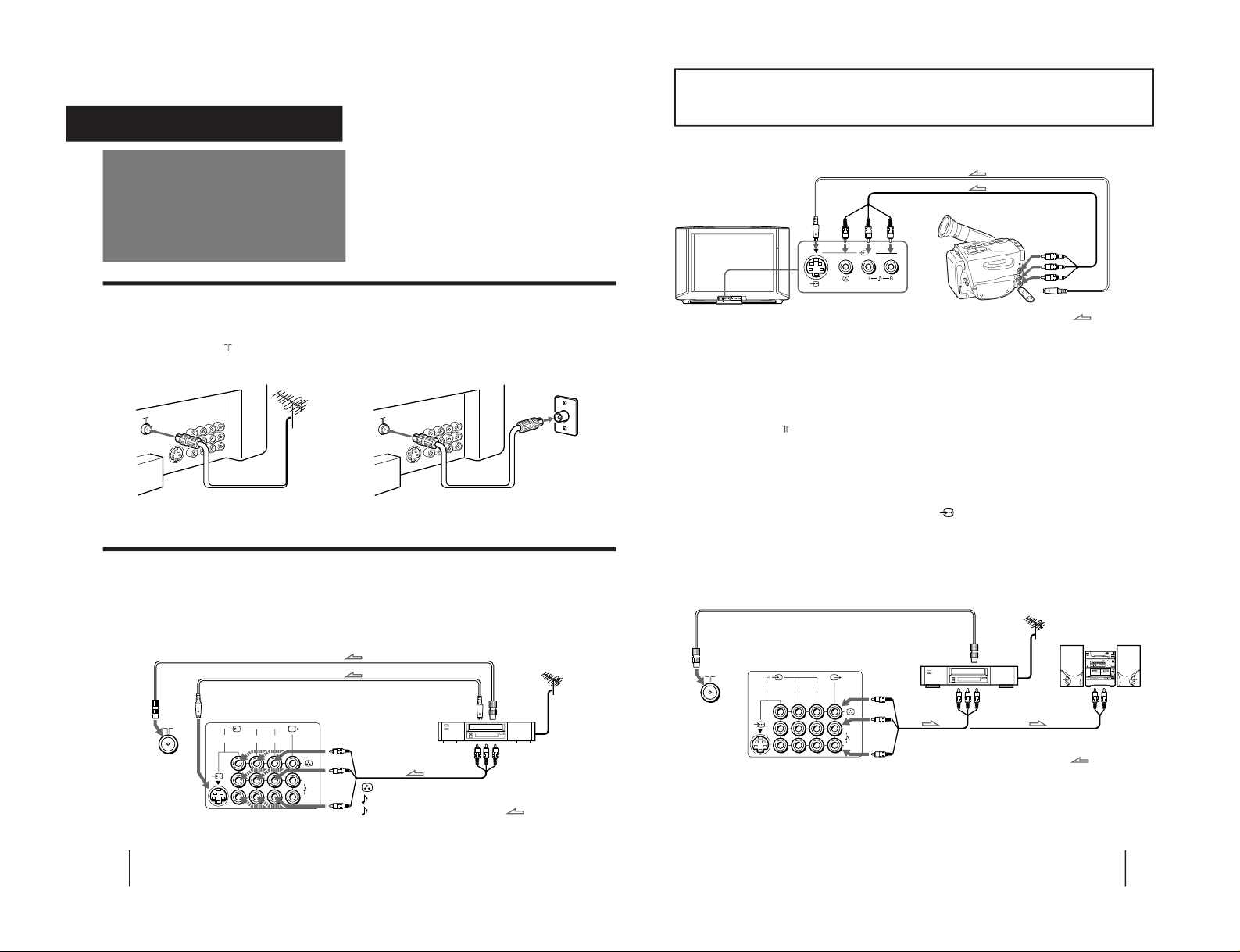
Connecting audio/video equipment using Ú (MONITOR/TV OUT) jacks
Front of TV
Camcorder
to S video output
to video and
audio outputs
: Signal flow
Rear of TV
VCR
to
antenna
output
to video and
audio inputs
D
(yellow)
≥
-L (white)
≥
-R (red)
Audio system
to audio
inputs
: Signal flow
to
antenna
socket
or
Getting Started
6
123
L
(MONO)
R
Connecting a VHF antenna or a combination VHF/UHF antenna
— 75-ohm coaxial cable (round)
Attach an optional IEC antenna connector to the 75-ohm coaxial cable.
Plug the connector into the
(antenna) socket at the rear of the TV.
Connecting optional equipment
You can connect optional audio/video equipment to your TV such as a VCR, multi disc player, camcorder, video
game or stereo system.
Connecting video equipment using video input jacks
Connections
On a wall
Rear of TV
Rear of TV
or
Rear of TV
(yellow)
-L (white)
-R (red)
VCR
to
S Video
output
to
antenna
output
to video and
audio outputs
: Signal flow
Getting Started
to
antenna
socket
to
S Video
input
– 4 –
SECTION 1
GENERAL
The operating instructions mentioned here are partial abstracts from the
Operating Instructions Manual. The page numbers of the Operating
Instruction Manual remain as in this manual.
RM-871
Page 5
Getting Started
8
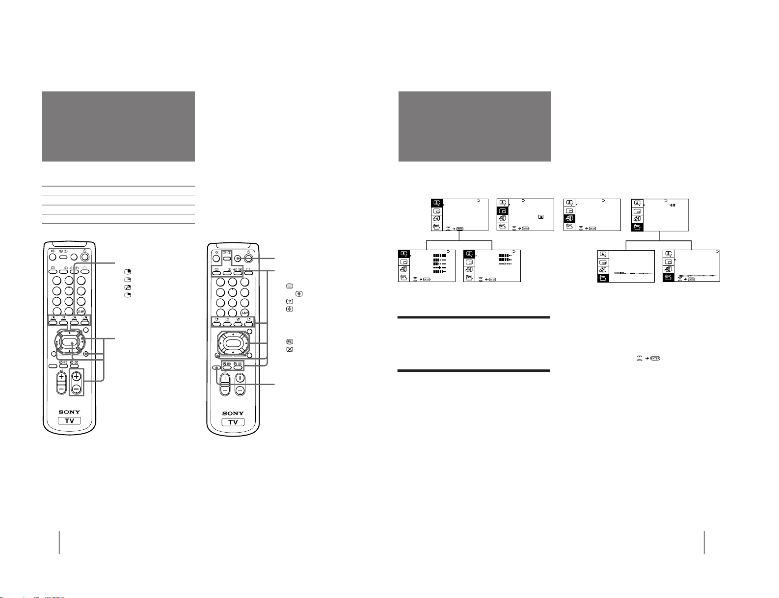
Names of buttons on the remote commander are indicated in different colors to represent the available functions.
Label color Button function
White For general TV operations.
Green For Teletext operations. (This is not used for this model)
Yellow For PIP and PROGRAM INDEX operations.
PROGR
MENU
PIP PROGR
GAME
PROGR
INDEX
PIP
TEXT
1
2
3
4
5
6
7
8
0
-/--
9
POWER
BASSO
ENTER
A/B
Getting to know the
remote commander
PIP operation buttons
(page 22)
(page 23)
(page 23)
(page 22)
V/v/ENTER
– for PIP PROGR (page 22)
PROGRAM INDEX
operation buttons
PROGR INDEX (page 21)
V/b/v/B/ENTER (page 21)
PROGR +/– (page 21)
GAME (page 27)
Teletext operation buttons
(This is not used for this model)
(page 24, 25)
A/B
(page 25)
(page 25)
(page 24)
[]
– Red (page 24)
[]
– Green (page 24)
[]
– Yellow (page 24)
[]
– Blue (page 24)
(page 24)
(page 25)
PIP TEXT (page 26)
V/b/v/B/ ENTER (page 26)
POWER BASSO (page 18)
PROGR
MENU
PIP PROGR
GAME
PROGR
INDEX
PIP
TEXT
1
2
3
4
5
6
7
8
0
-/--
9
POWER
BASSO
ENTER
A/B
Getting Started
9
Introducing the
menus
You can preset TV channels, adjust the picture and sound qualities, and select some settings using the on-screen
menus. You can use the buttons on both the remote commander and the TV to operate the menus.
A/V CONTROL
PIP
FEATURES
Getting back to the previous menu
(except for AUTO PROGRAM)
Press V or v to move the cursor (z) to the first
line (N) of each menu, and press ENTER.
Cancelling the menu screen
Press MENU.
Notes (except for AUTO PROGRAM)
• When a menu is selected after pressing ENTER, the color of
both the menu and the menu symbol change and the cursor
(z) appears beside the first item of the menu.
• When an item on the menu is selected after pressing ENTER,
the color of the item changes.
• You can refer to the guide (
) at the bottom of the
menus (except for the PRESET menu) for the basic operations
of the menu.
• If more than approximately 60 seconds elapse after you press a
button, the menu screen disappears automatically.
PIP
PIP: OFF
PIP TEXT
STRO BE
POS I T ION:
PROGR I ND EX
PRESET
BASS
80
00
80
TREBLE
BALANCE
AUDIO AD JUST
PRESET
SKIP:
PR02 OFF
TV SYS: B / G
COL
SYS : AUTO
ENGL I SH
AUTO P ROGRAM
MANUAL P ROGRAM
LA NGUAGE /
:
P I C TURE
40
100
0
80
V I DEO ADJUST
COLOR
BR I GHT
HUE
SHARP
VM: HIGH
45
0
TV SYS: B / G
AUTO P ROGRAM
VHF LO
W
PR: 0 1
TV SYS: B / G
VHF
LOW
PR: 0 1
AT T : OFF
MANUAL P ROGRAM
GAME MODE
HYPER SURROUND:
OF F
MONITOR
AV OUT :
FE ATURES
A / V CONTROL
DYNAMIC
SOFT
STA NDARD
PERSONAL
V I DEO ADJUST
AUDIO AD JUST
*
( This is not used for this model)
*
– 5 –
KV-LX34M50
RM-871
Page 6
10
Getting Started
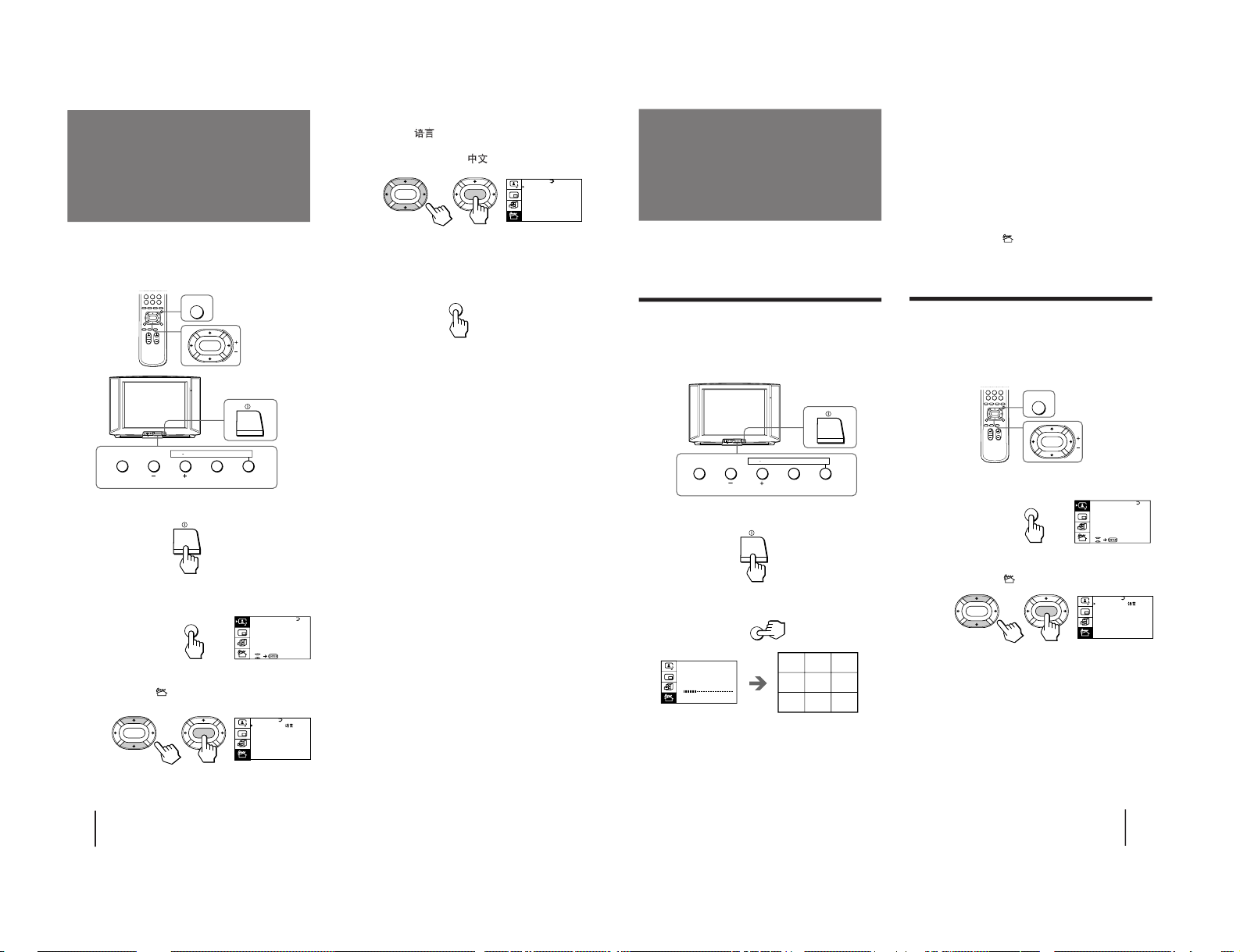
Changing the menu
language
p KV-LX34M31
If you prefer Chinese to English, you can change the
menu language. You can use buttons on both the
remote commander and the TV.
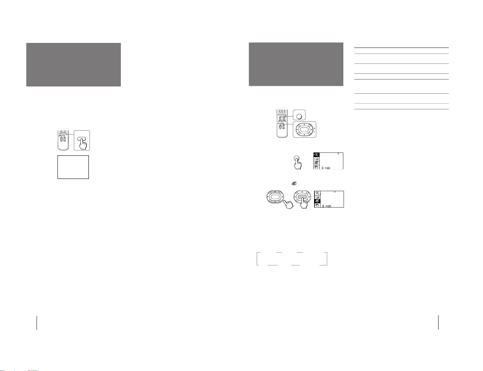
1
Press U to turn on the TV.
2
Press MENU.
3
Press V or v to move the cursor (”) to the
PRESET menu ( ), and press ENTER.
MENU
ENTER
4
Make sure the cursor (
”
) appears beside
LANGUAGE/
, and press ENTER.
5
Press V/b/v/B to select
, and press ENTER.
All of the menus change to Chinese.
6
Press MENU to return to the normal screen.
PRESET
SKIP: PR02 OFF
TV SYS: B/G
COL SYS: AUTO
ENGL I SH
AUTO P ROGRAM
MANUAL PROGRAM
LA NGUAGE /
:
ENTER ENTER
ENTER MENU AUTO
PROGR
ONE PUSH AUTOMATIC PROGRAMMING
A / V CONTROL
DYNAMIC
SOFT
STA NDARD
PERSONAL
V I DEO ADJ UST
AUDI O ADJ UST
MENU
MENU
„w‡]
‚ı¶V W„D¡GPR02 ˆ
„q ł¤t†˛¡GB/G
–mƒ ¤ ƒ¡¡Gƒ ˚
⁄⁄⁄
ƒ˚‰¥x
⁄˚‰¥x
»y¤¥/ L ANGUAGE
:
ENTER
ENTER
Getting Started
11
You can preset TV channels easily by storing all the
receivable channels automatically. You can also preset
channels manually or disable program positions (see
page 12 ).
Presetting channels automatically
You can preset up to 100 TV channels in numerical
sequence from the program position 1. You can preset
channels automatically using the button on the TV or
the menu.
1
Press U to turn on the TV.
2
Press AUTO PROGR.
The TV starts scanning and presetting channels
automatically. When all of the receivable channels
are stored, the AUTO PROGRAM menu disappears
and the first nine preset TV programs appear on
the nine sub screens. The nine sub screens
disappear after being displayed for several seconds.
Presetting channels
Note
• If you want to return to the normal screen while the nine sub
screens are being displayed, you can press PROGR INDEX on
the remote commander.
To preset channels automatically using
the menu
1 Press MENU.
2 Press V or v to move the cursor (z) to the
PRESET menu (
), and press ENTER.
3 Press V or v to move the cursor (z) to AUTO
PROGRAM, and press ENTER.
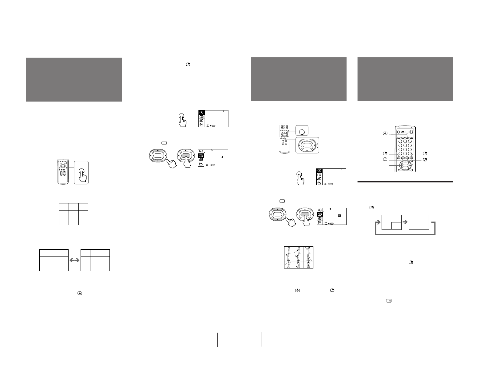
Presetting channels manually
To change the program position for a channel or to
receive a channel with a weak signal which you cannot
receive by automatic presetting, preset the channel
manually.
1
Press MENU.
2
Press V or v to move the cursor (z) to the
PRESET menu (
), and press ENTER.
3
Select your local TV system.
(1) Press V or v to move the cursor (z) to TV SYS, and
press ENTER.
(2) Press V/b/v/B until your local TV system appears
on the menu, and press ENTER.
MENU
ENTER
PRESET
SKIP: PR02 OFF
TV SYS: B/G
COL SYS: AUTO
ENGL I SH
AUTO P ROGRAM
MANUAL PROGRAM
LA NGUAGE /
:
ENTER
ENTER
A / V CONTROL
DYNAMIC
SOFT
STA NDARD
PERSONAL
V I DEO ADJ UST
AUDI O ADJ UST
MENU
ENTER MENU AUTO
PROGR
ONE PUSH AUTOMATIC PROGRAMMING
TV SYS:B/G
AUTO P ROGRAM
VHF LO
W
PR: 01
123
456
789
AUTO
PROGR
KV -LX34M50
RM-871
– 6 –
Page 7
Getting Started
12
Disabling program positions
By disabling unused or unwanted program positions,
you can skip those positions when you press PROGR
+/–.
1
Press MENU.
2
Press V or v to move the cursor (z) to the
PRESET menu (
), and press ENTER.
3
Press V or v to move the cursor (z) to SKIP,
and press ENTER.
4
Press V or v until the unused or unwanted
program position appears on the menu,
and press ENTER.
5
Press V/b/v/B to select ON, and press ENTER.
6
To disable other program positions, repeat
steps 4 and 5.
7
Press MENU to return to the normal screen.
To cancel the skip setting
1 Display the PRESET menu.
2 Press V or v to move the cursor (z) to SKIP, and
press ENTER.
3 Press V or v until the program position you want to
cancel the skip setting appears, and press ENTER.
4 Press V/b/v/B to select OFF, and press ENTER.
4
Press V or v to move the cursor (z) to
MANUAL PROGRAM, and press ENTER.
5
Select the program position to which you
want to preset a channel.
(1) Make sure the cursor (z) appears beside PR, and
press ENTER.
(2) Press V/b/v/B until the program position you
want appears on the menu, and press ENTER.
6
Select the desired channel.
(1) Press V or v to move the cursor (z) to VHF LOW,
and press ENTER.
(2) Press V/b/v/B until the desired channel picture
appears on the TV screen, and press ENTER.
7
Press MENU to return to the normal screen.
If the TV signal is too strong
The picture may be distorted. You can reduce the
picture distortion as described below.
1 Display the PRESET menu.
2 Press V or v to move the cursor (z) to MANUAL
PROGRAM, and press ENTER.
3 Press V or v to move the cursor (z) to ATT, and
press ENTER.
4 Press V/b/v/B to select ON, and press ENTER.
If the TV system is not properly selected
The picture color may be poor and/or the sound may
be noisy. In this case, select the appropriate TV system.
1 Press PROGR +/– or the number buttons to select
the program position.
2 Display the PRESET menu.
3 Press V or v to move the cursor (z) to TV SYS, and
press ENTER.
4 Press V/b/v/B until the appropriate TV system
appears, and press ENTER.
Notes
• The TV system and the ATT (attenuator) settings are
memorized for each program position.
• If you do not know your local TV system, consult your nearest
Sony dealer or authorized service center.
TV SYS:B/G
VHF
LOW
PR: 01
ATT : OFF
MANUAL PROGRAM
ENTER
ENTER
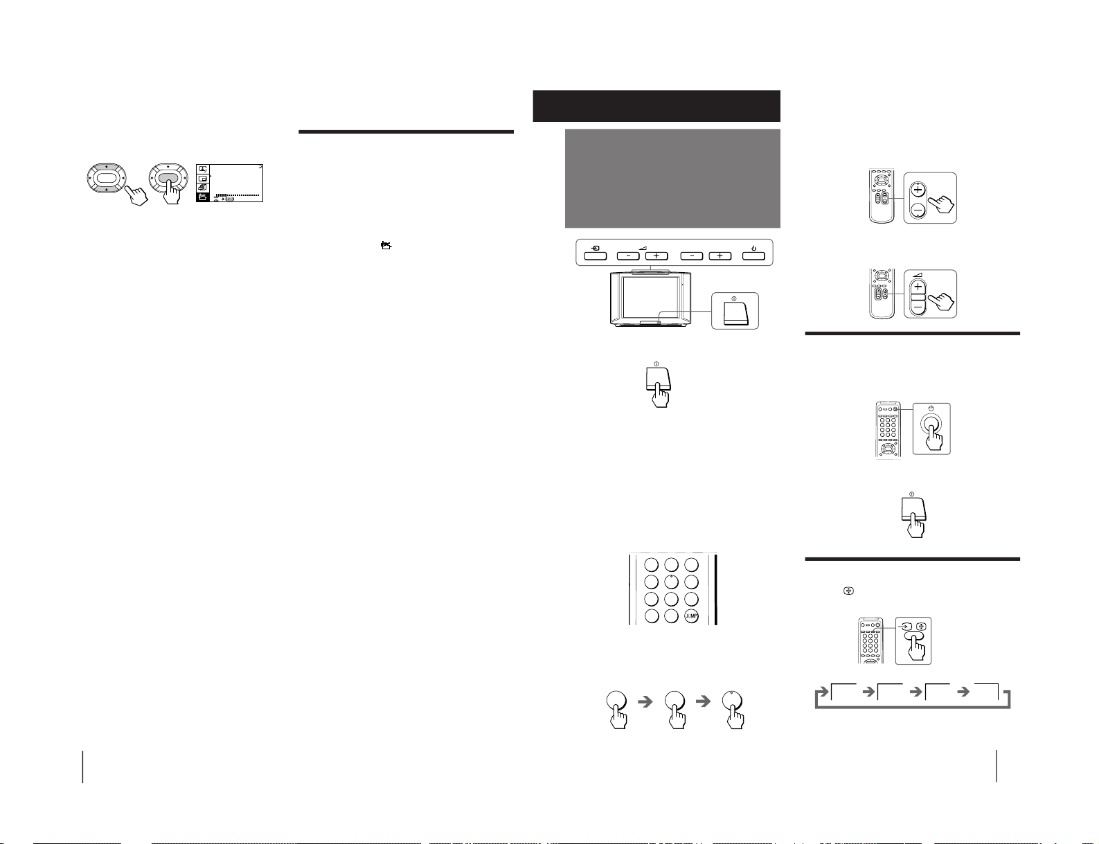
Operations
13
Watching the TV
To scan through program positions
Press PROGR +/– on the remote commander or the
TV until the program position you want appears.
3
Press Á +/– on the remote commander or
the TV to adjust the volume.
Turning off the TV
To turn off the TV temporarily
Press u on the remote commander or the TV. The u
indicator lights up.
To turn off the TV completely
Press U on the TV.
Watching the video input
Press …
on the remote commander or … on
the TV.
1
Press U to turn on the TV.
When the TV is turned on in the standby mode, the
u indicator on the TV lights up. To turn on the TV
completely, press u on the remote commander or
the TV. When the TV is turned on completely, the
PROGR +/–, Á +/–, and … indicators on the TV
light up.
2
Select the TV program you want to watch.
To select a program position directly
Press the number button.
To select a two-digit program position, press “÷”
before the number buttons.
For example: to select program position 25, press
“÷,” then “2” and “5.”
PROGR
2
-/--
5
VIDEO 1
VIDEO 2 VIDEO 3
1
Operations
1
2
3
4
5
6
7
8
0
-/--
9
PROGR
– 7 –
KV-LX34M50
RM-871
Page 8
Operations
14
To watch TV
Press ; on the remote commander or … on the TV.
Switching back quickly to the previous
channel
Press JUMP.
Muting the sound
Press ¤.
Displaying the on-screen information
Press
.
Note
• The on-screen display shows the program position or the video
mode, the picture and sound information. The on-screen
display for the picture and sound information disappears after
being displayed for approximately three seconds.
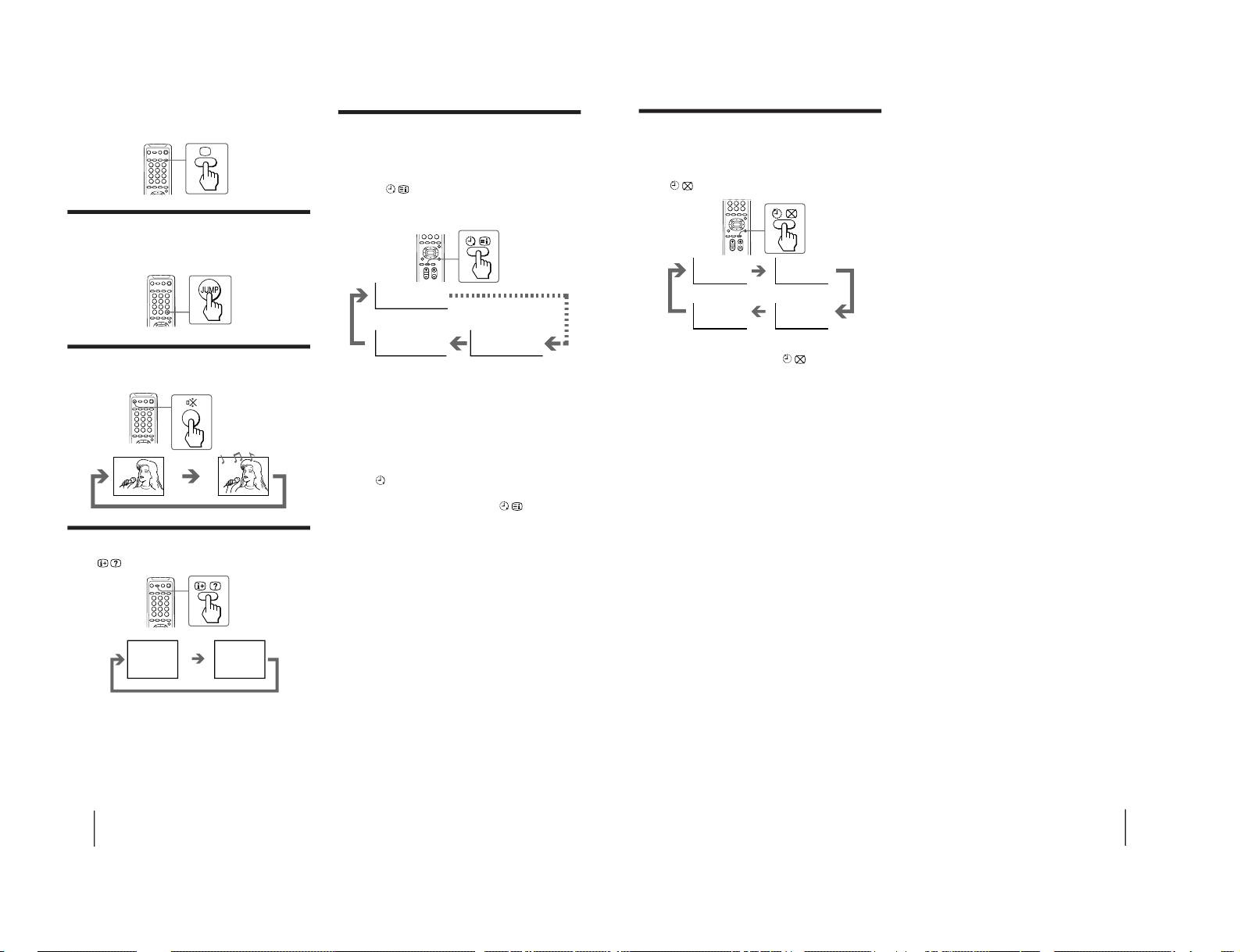
Setting the Wake Up Timer
You can set the TV to turn on automatically after the
period of time you want.
1
Press repeatedly to set the timer.
The on-screen display appears.
2
If you want a particular TV program or
video mode to be displayed using the Wake
Up Timer, select the TV program or video
mode.
3
Press u on the remote commander or the
TV, or set the Sleep Timer to turn off the TV
in the standby mode.
The
indicator lights up in amber color.
To cancel the Wake Up Timer, press
repeatedly
until “WAKE UP TIMER: OFF” appears, or turn off the
main power of the TV.
Notes
• The Wake Up Timer starts immediately after the on-screen
display disappears.
• The last TV program position or video mode just before the TV
turns into the standby mode will appear when the TV is turned
on using the Wake Up Timer.
• If no buttons or controls are pressed for more than two hours
after the TV is turned on using the Wake Up Timer, the TV
automatically turns into the standby mode. If you want to
continue watching the TV, press any button or control on the
TV or remote commander.
MUTING
After 10 minutes
After 12 hours
No Wake Up Timer
POWER BASSO: ON
DYNAMIC
8
WAKE UP TIMER:10M
WAKE UP TIMER:OFF
WAKE UP TIMER:12H00M
Operations
15
Setting the Sleep Timer
You can set the TV to turn off automatically after the
period of time you want.
Press
.
To cancel the Sleep Timer, press
repeatedly until
“SLEEP TIMER: OFF” appears, or turn the TV off.
After 30 minutes
After 60 minutes
No Sleep Timer
After 90 minutes
SLEEP TIMER:30M SLEEP TIMER:60M
SLEEP TIMER:OFF
SLEEP TIMER:90M
KV -LX34M50
RM-871
– 8 –
Page 9
Operations
16
A / V CONTROL
DYNAMIC
SOFT
STA NDARD
PERSONAL
V I DEO ADJ UST
AUDI O ADJ UST
MENU
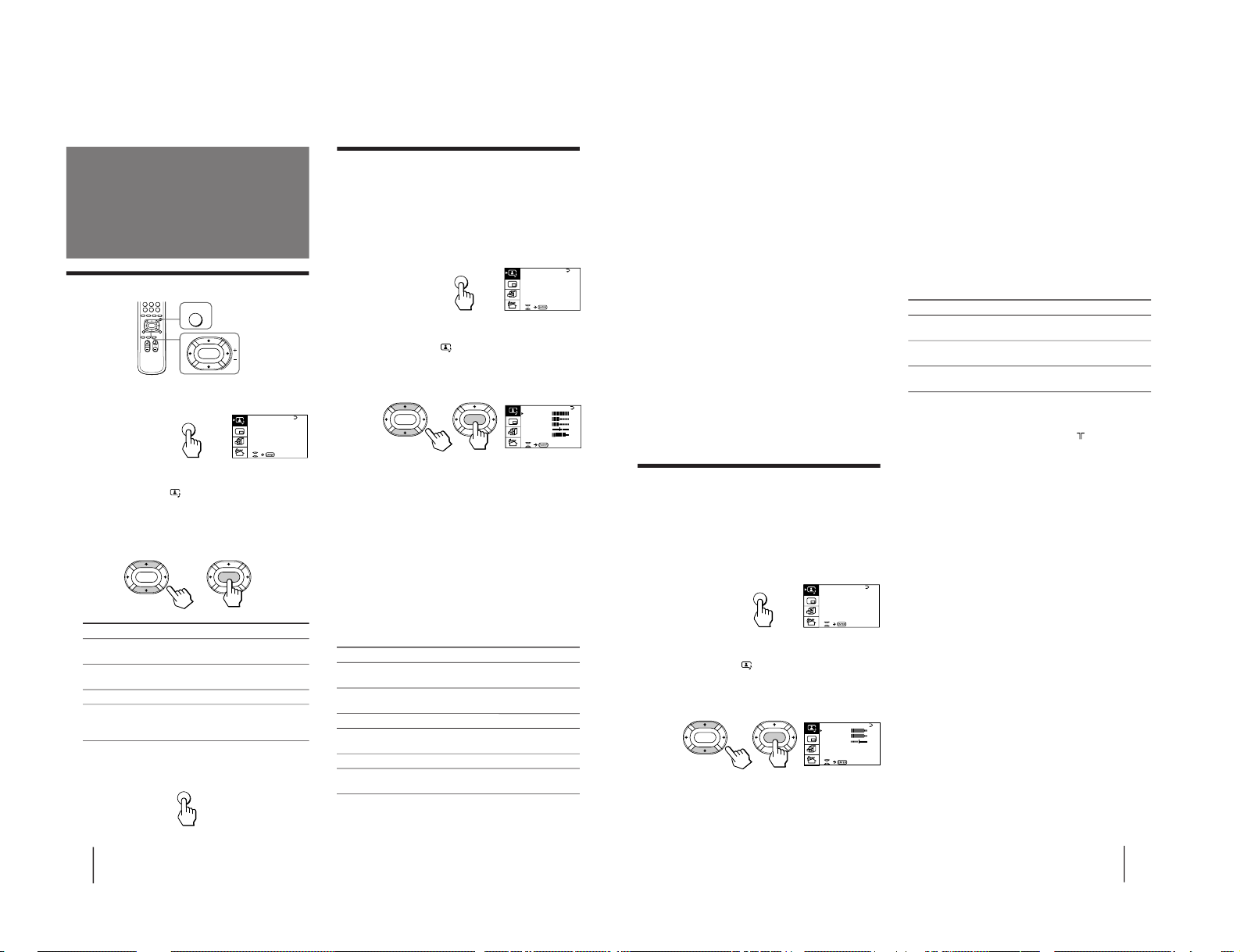
Selecting the picture and sound modes
1
Press MENU.
2
Make sure the cursor (”) appears in the A/V
CONTROL menu (
), and press ENTER.
3
Press V or v to move the cursor (”) to
DYNAMIC, STANDARD, SOFT, or PERSONAL,
and press ENTER.
Select To
DYNAMIC Receive high contrast picture with
powerful sound.
STANDARD Receive normal contrast picture with
medium listening sound.
SOFT Receive mild picture with soft sound.
PERSONAL Receive the last picture and sound
settings that are adjusted using VIDEO
ADJUST and AUDIO ADJUST.
4
Press MENU to return to the normal screen.
Adjusting the
picture and sound
MENU
ENTER
ENTER ENTER
MENU
Press V/b
Increase picture
contrast.
Increase color
intensity.
Brighten the picture.
Make picture tones
become greenish.
Sharpen the picture.
Increase emphasis on
picture edges.
Adjusting the picture settings
(VIDEO ADJUST)
You can adjust the picture settings to suit your taste
with the VIDEO ADJUST option. The adjusted settings
are stored in the PERSONAL option.
1
Press MENU.
2
Make sure the cursor (”) appears in the A/V
CONTROL menu (
), and press ENTER.
3
Press V or v to move the cursor (”) to VIDEO
ADJUST, and press ENTER.
4
Press V or v to move the cursor (”) to the
item you want to adjust, and press ENTER.
5
Press V/b/v/B to adjust the selected item,
and press ENTER.
For details on each item, see “Description of adjustable
items” below.
6
To adjust other items, repeat steps 4 and 5.
7
Press MENU to return to the normal screen.
Description of adjustable items
Item Press v/B
PICTURE Decrease picture
contrast.
COLOR Decrease color
intensity.
BRIGHT Darken the picture.
HUE Make picture tones
become reddish.
SHARP Soften the picture.
VM Decrease emphasis
on picture edges.
Note
• You can adjust HUE for the NTSC system only.
P I CT URE
40
100
0
80
V I DEO ADJ UST
COLOR
BR I GHT
HUE
SHARP
VM: HIGH
45
0
ENTER
ENTER
A / V CONTROL
DYNAMIC
SOFT
STA NDARD
PERSONAL
V I DEO ADJ UST
AUDI O ADJ UST
MENU
Operations
17
A / V CONTROL
DYNAMIC
SOFT
STA NDARD
PERSONAL
V I DEO ADJ UST
AUDI O ADJ UST
MENU
Press V/b
Increase the bass
sound.
Increase the treble
sound.
Increase the right
speaker's volume.
If the picture is slightly snowy
You may try to improve the picture by changing the
VM setting as described below:
1 Display the VIDEO ADJUST menu.
2 Press V or v to move the cursor (”) to VM, and
press ENTER.
3 Press V/b/v/B to select LOW, and press ENTER.
If the picture color is abnormal when receiving
programs through the ˘ (antenna) terminal
Change the color system or the TV system from the
PRESET menu as described below until the color
becomes normal.
1 Display the PRESET menu.
2 Press V or v to move the cursor (”) to
COL SYS or TV SYS, and press ENTER.
3 Press V/b/v/B to change the color system or the
TV system until the color becomes normal, and
press ENTER.
Note
• Normally set the color system (COL SYS) to AUTO.
Adjusting the sound settings
(AUDIO ADJUST)
You can adjust the sound settings to suit your taste
with the AUDIO ADJUST option. The adjusted settings
are stored in the PERSONAL option.
1
Press MENU.
2
Make sure the cursor (”) appears in the A/V
CONTROL menu (
), and press ENTER.
3
Press V or v to move the cursor (”) to
AUDIO ADJUST, and press ENTER.
4
Press V or v to move the cursor (”) to the
item you want to adjust, and press ENTER.
5
Press V/b/v/B to adjust the selected item,
and press ENTER.
For details on each item, see “Description of adjustable
items” below.
6
To adjust other items, repeat steps 4 and 5.
7
Press MENU to return to the normal screen.
Description of adjustable items
Item Press v/B
BASS Decrease the bass
sound.
TREBLE Decrease the treble
sound.
BALANCE Increase the left
speaker's volume
If the sound is distorted or noisy when
receiving programs through the
(antenna)
terminal
Change the TV system from the PRESET menu as
described below until the sound becomes normal.
1 Display the PRESET menu.
2 Press V or v to move the cursor (”) to TV SYS, and
press ENTER.
3 Press V/b/v/B to change the TV system until the
sound becomes normal, and press ENTER.
BASS
80
00
80
TREBLE
BALANCE
AUDI O ADJ UST
ENTER
ENTER
– 9 –
KV-LX34M50
RM-871
Page 10
KV -LX34M50
Operations
18
Listening to the
POWER BASSO
sound
The POWER BASSO sound enables you to enjoy a high
quality sound mode with the best combination of all
types of sound. It reproduces dynamic and clear
sounds and emphasizes low and high audio effects as
well.
Press POWER BASSO.
The sound mode of the TV program or the video input
changes to the POWER BASSO sound.
To restore the previous sound mode
Press POWER BASSO again.
Note
• You can select any of the surround sound modes (HYPER
SURROUND) to cancel the POWER BASSO sound.
POWER
BASSO
POWER BASSO: ON
Operations
19
A / V CONTROL
DYNAMIC
SOFT
STA NDARD
PERSONAL
V I DEO ADJ UST
AUDI O ADJ UST
MENU
Description of adjustable items
Select To
MOVIE Listen to a sound that emphasizes the bass
audio effect of movie theater.
MUSIC Listen to a dynamic and clear sound that
emphasizes the low and high audio effect.
NEWS〈BBE〉 Listen to a sound that emphasizes voice.
HALL〈SRS〉 Listen to a sound that spreads out over a
large area, giving the feeling of being at a
concert hall.
SPACE Listen to a monaural sound that gives a
stereo-like effect.
OFF Turn off the surround sound.
Notes
• The BBE is manufactured by Sony Corporation under license
from BBE Sound, Inc. It is covered by U.S. Patent No. 4,638,258
and No. 4,482,866. The word “BBE” and the BBE symbol are
the trademarks of BBE Sound, Inc.
• The (r)® SRS (SOUND RETRIEVAL SYSTEM) is
manufactured by Sony Corporation under license from SRS
Labs, Inc. It is covered by U.S. Patent No. 4,748,669.
The word “SRS” and the SRS symbol (r) are registered
trademarks of SRS Labs, Inc.
Listening to the
surround sound
(HYPER SURROUND)
MENU
ENTER
GAME MODE
HYPER SURROUND:
OFF
MONITOR
AV OUT :
FE ATURES
ENTER
ENTER
The HYPER SURROUND feature enables you to enjoy
a surround sound effect that is like being in a concert
hall or movie theater when receiving stereo signals.
1
Press MENU.
2
Press V or v to move the cursor (z) to the
FEATURES MENU (
) , and press ENTER.
3
Press V or v to move the cursor (z) to
HYPER SURROUND, and press ENTER.
4
Press V/b/v/B to select MOVIE, MUSIC,
NEWS〈BBE〉, HALL〈SRS〉 or SPACE, and press
ENTER.
n MOVIE n MUSIC n NEWS〈BBE〉
OFF N SPACE N HALL〈SRS〉 N
For details on each item, see “Description of adjustable
items“ below.
5
Press MENU to return to the normal screen.
RM-871
– 10 –
Page 11
Operations
21
A / V CONTROL
DYNAMIC
SOFT
STA NDARD
PERSONAL
V I DEO ADJ UST
AUDI O ADJ UST
MENU
To restore the normal screen
Press PROGR INDEX again or
.
You can also select PROGR INDEX or PIP : OFF from
the PIP menu, and press ENTER to restore the normal
screen.
To view multiple programs on the nine sub
screens using the menu
1
Press MENU.
2
Press V or v to move the cursor (z) to the
PIP menu (
), and press ENTER.
3
Make sure the cursor (z) appears beside
PROGR INDEX, and press ENTER.
Notes
• You can change the position of the nine sub screens using the
PIP menu (as described in “Changing the position of the PIP
screen” on page 23).
• You can hear the sound of the main screen when viewing
multiple programs on the nine sub screens.
• You can use the number buttons on the remote commander to
change the program position of the main screen when viewing
multiple programs on the nine sub screens.
Viewing multiple
programs at the
same time
(PROGRAM INDEX)
The PROGRAM INDEX feature allows you to view all
the preset TV programs and the video inputs on the
nine sub screens within the main screen at the same
time.
You can view multiple programs on the nine sub
screens using the button on the remote commander or
the menu.
Press PROGR INDEX.
The first nine preset programs appear on the nine sub
screens.
To view the next or the previous nine preset
programs on the nine sub screens
Press PROGR +/– on the remote commander or the TV.
To select the program you want to watch
directly after viewing multiple programs on
the nine sub screens
Press the number buttons, …
, or press
V/b/v/B to move the cursor (>>>) that appears on the
first screen to the screen of the program you want to
watch, and press ENTER.
PROGR
INDEX
123
456
789
>>>
123
456
789
10 11 12
V1 V2 V3
123
>>> >>>
PIP
PIP: OFF
STROBE
POS I T ION:
PROGR I ND EX
ENTER
ENTER
Operations
22
With the Picture-in-Picture (PIP) feature, you can
display a sub screen within the main picture of
different TV programs or video inputs.
Displaying the PIP screen
You can display the PIP screen using the button on the
remote commander or the menu.
Press
.
Selecting a TV program or video input in the
PIP screen
To select a TV program, press V or v, and press
ENTER.
To select a video input, press
on the remote
commander or … on the TV.
To display the PIP screen using the menu
1
Press MENU.
2
Press V or v to move the cursor (”) to the
PIP menu (
), and press ENTER.
3
Press V or v to move the cursor (”) to PIP,
and press ENTER.
4
Press V/b/v/B to select ON, and press ENTER.
5
Press MENU to return to the normal screen.
Using the Picture-inPicture (PIP)
features
Displaying frameby-frame pictures
(STROBE)
You can watch a slow motion movement of the main
screen picture which is displayed frame-by-frame on
the nine sub screens within the main screen.
1
Press MENU.
2
Press V or v to move the cursor (z) to the
PIP menu (
), and press ENTER.
3
Press V or v to move the cursor (z) to
STROBE, and press ENTER.
To restore the normal screen
Select STROBE again or PIP : OFF from the PIP menu,
and press ENTER.
You can also press ;, …
, PROGR +/–, or
to
restore the normal screen.
Notes
• You can change the position of the nine sub screens using the
PIP menu (as described in "Changing the position of the PIP
screen" on page 23).
• You can hear the normal sound when using the STROBE
feature.
MENU
ENTER
PIP
PIP: OFF
STROBE
POS I T ION:
PROGR I ND EX
ENTER
ENTER
;
…
V/v/ENTER
1
2
3
4
5
6
7
8
0
9
A / V CONTROL
DYNAMIC
SOFT
STA NDARD
PERSONAL
V I DEO ADJ UST
AUDI O ADJ UST
MENU
– 11 –
KV-LX34M50
RM-871
Page 12
KV -LX34M50
Operations
23
A / V CONTROL
DYNAMIC
SOFT
STA NDARD
PERSONAL
V I DEO ADJ UST
AUDI O ADJ UST
MENU
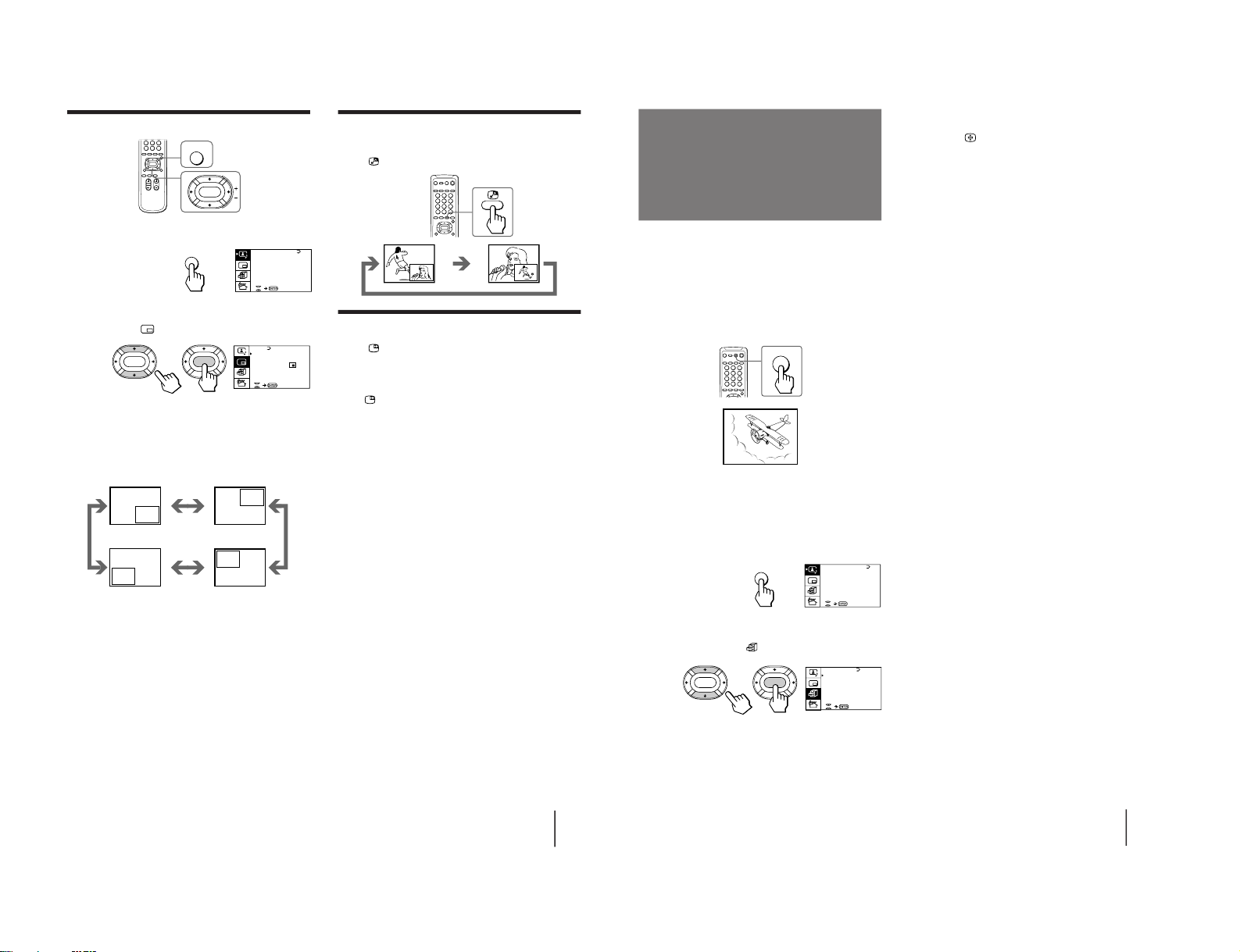
Swapping pictures between the main
and PIP screens
Press
.
Freezing the PIP screen
Press .
The PIP screen will freeze.
To restore the normal screen
Press
again.
Notes
• When you display a video input on the PIP screen at an
abnormal speed, the picture may be noisy depending on the
VCR.
• If you display different color systems on the main screen and
the PIP screen, the size of the PIP screen may be different and
the PIP picture may be noisy. This does not indicate a
malfunction of the TV.
Changing the position of the PIP screen
1
Press MENU.
2
Press V or v to move the cursor (”) to the
PIP menu (
), and press ENTER.
3
Press V or v to move the cursor (z) to
POSITION, and press ENTER.
4
Press V/b/v/B to select the position you
want, and press ENTER.
5
Press MENU to return to the normal screen.
PIP
PIP: OFF
STROBE
POS I T ION:
PROGR I ND EX
ENTER ENTER
MENU
ENTER
Operations
27
A / V CONTROL
DYNAMIC
SOFT
STA NDARD
PERSONAL
V I DEO ADJ UST
AUDI O ADJ UST
MENU
To restore the normal picture and sound
modes
Press ;, …
, or PROGR +/–.
Notes
• If you press the GAME button when the TV is in the standby
mode, the TV turns on automatically and the picture and
sound change to the mode that is suitable for a video game.
• To display a video game screen, connect the video game
equipment to the … 3 (VIDEO 3 INPUT) jacks at the front of
the TV or the … (VIDEO IN) 3 jacks at the rear of the TV.
The GAME MODE feature enables you to view a video
game screen in the optimum mode that gives soft
picture and dynamic sound effect.
You can display a video game screen using the button
on the remote commander or the menu.
Press GAME.
The picture and sound change to the mode that is
suitable for a video game.
To view a video game screen using the menu
1
Press MENU.
2
Press V or v to move the cursor (z) to the
FEATURES menu (
), and press ENTER.
3
Make sure the cursor (z) appears beside
GAME MODE, and press ENTER.
Viewing a video
game screen
(GAME MODE)
GAME
GAME
GAME MODE
HYPER SURROUND:
OFF
MONITOR
AV OUT :
FE ATURES
ENTER
ENTER
RM-871
– 12 –
Page 13
Operations
28
Customizing the TV
Using the AV OUT (advanced rec-out)
terminal
You can select the output signal from the Ú
(MONITOR/TV OUT) jacks at the rear of the TV.
However, the signals of the PROGRAM INDEX,
STROBE, PIP modes cannot be output even though
MONITOR is selected.
1
Press MENU.
2
Press V or v to move the cursor (z) to the
FEATURES menu (
), and press ENTER.
3
Press V or v to move the cursor (z) to AV
OUT, and press ENTER.
4
Press V/b/v/B to select the output signal,
and press ENTER.
Select To
TV Output the signal of the TV broadcast.
MONITOR Output the signal of the picture you are
watching as a main picture.
Note
• Do not change the channel while recording with a VCR
through the Ú (MONITOR/TV OUT) jacks. If you change the
channel, it also changes the channel you are recording.
A / V CONTROL
DYNAMIC
SOFT
STA NDARD
PERSONAL
V I DEO ADJ UST
AUDI O ADJ UST
MENU
GAME MODE
HYPER SURROUND:
OFF
MONITOR
AV OUT :
FE ATURES
ENTER
ENTER
Operations
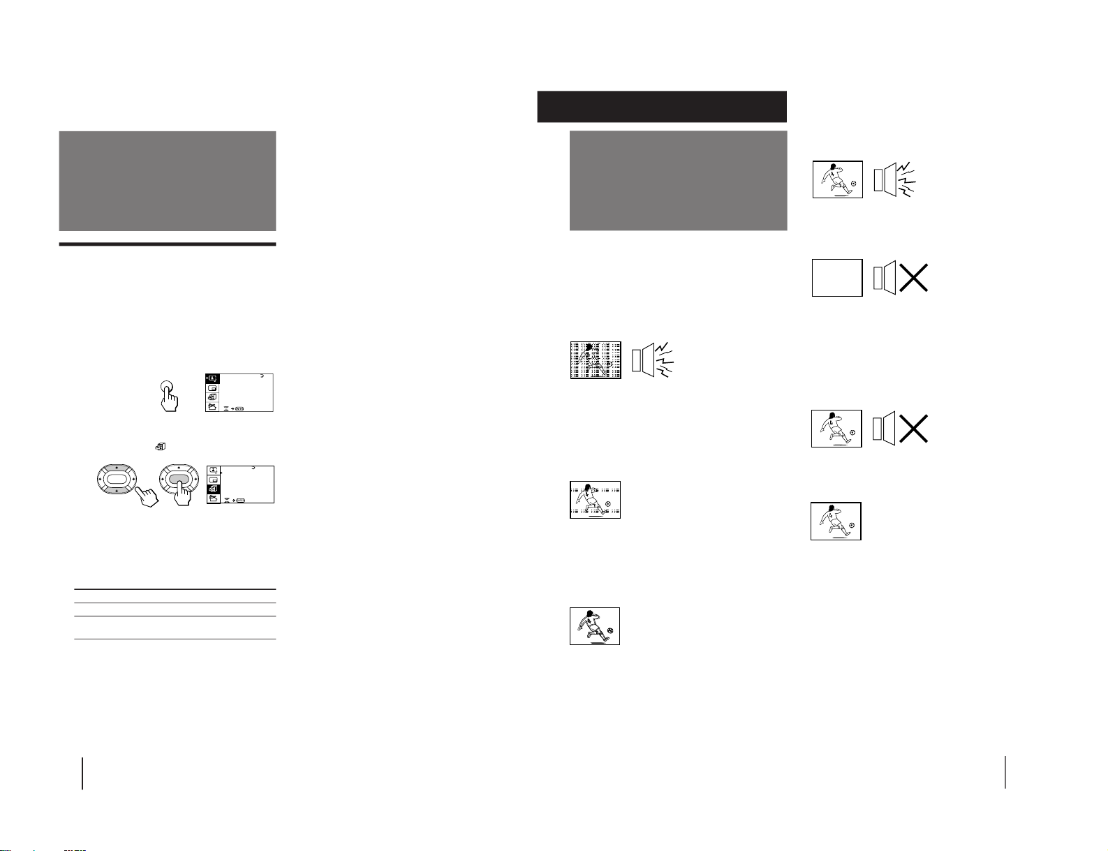
29
Troubleshooting
Good picture
Noisy sound
/Check the TV system (TV SYS) setting.
No picture
No sound
/Press u.
/Press U to turn off the TV for about five
seconds and then turn it on again.
/Check the power cord connection.
/Check the antenna connection.
/Check the VCR connections.
Good picture
No sound
/ Press Á +.
/ Press ¤.
No color
/Adjust the COLOR level in the VIDEO
ADJUST menu of the PERSONAL option.
/Check the color system (COL SYS) setting.
TV cabinet creaks
/Even if the picture or the sound is normal,
changes in the room temperature
sometimes make the TV cabinet expand or
contract, making a noise. This does not
indicate a malfunction.
Additional Information
If you have any problems, read this manual again and
check the countermeasure for each of the symptoms
listed below.
If the problem persists, contact your nearest Sony
dealer or authorized service center.
Snowy picture
Noisy sound
/Check the antenna.
/Check the antenna connection on the TV
and on the wall.
/Check the TV system (TV SYS) setting.
/Check the ATT (attenuator) setting.
Dotted lines or stripes
/This may be caused by local interference
(e.g. cars, neon signs, hair dryers, etc.).
Adjust the antenna for minimum
interference.
Double images or “ghosts”
/This may be caused by reflections from
nearby mountains or buildings. A highly
directional antenna may improve the
picture.
Additional Information
– 13 –
KV-LX34M50
RM-871
Page 14

Getting Started
5
WARNING
• Dangerously high voltages are present inside the TV.
• Operate the TV only at 110-240 V AC.
• Do not open the cabinet and the rear cover of the TV.
Refer servicing to qualified personnel.
• To prevent fire or shock hazard, do not expose the TV
to rain or moisture.
• Do not operate the TV if any liquid or solid object
falls into it. Have it checked immediately by qualified
personnel only.
• Do not block the ventilation openings.
• Do not install the appliance in a confined space, such
as a bookcase or built-in cabinet.
• Do not install the TV in hot, humid or excessively
dusty places.
• Do not install the TV where it may be exposed to
mechanical vibrations.
• Do not keep the TV plugged in if you are not going to
use it for several days.
• Do not pull the power cord to disconnect the TV. Pull
it out by the plug.
• Use only the supplied screws (as shown on page 2) to
fasten the TV to the TV stand or to stabilize the TV
against a wall or a pillar. Use of other screws may
damage the TV.
Note on the remote commander
• The supplied remote commander is used on several models of
the TV. If you do not find instructions for some controls that
are on the remote commander, that means your TV does not
employ the features of those controls, e.g.
.
Notes
• When you turn on the TV, you may hear the “boon” sound
that is caused by the demagnetization of the TV. This does not
indicate a malfunction.
• The picture color may become abnormal if you change the
direction of your TV. To obtain the normal picture color, press
U or u on the TV to turn off the TV for five minutes and then
turn it on again.
– 14 –
KV -LX34M50
RM-871
Page 15

SECTION 2
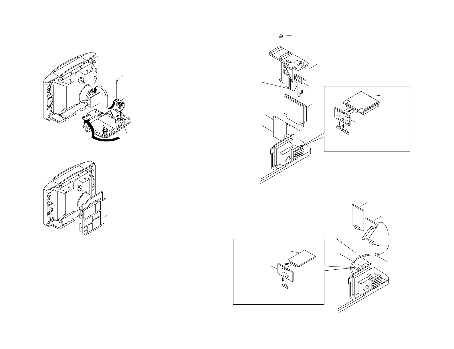
3 Connector
2 3D speaker box
1 Three screws (step hilo tapping)
Two screws (washer head)
(+BVTP 4 × 16)
Speaker brock assy
1
2
Three screws
(+BVTP 4 × 16)
1
Ten screws
(+BVTP 4 × 16)
2
Chassis assy
Two claws
2
1
DISASSEMBLY
2-1. 3D SPEAKER BOX REMOVAL
Note: Remove 3D SPEAKER BOX before you remove REAR COVER.
– 15 –
2-2. REAR COVER REMOVAL
2-3. SPEAKER REMOVAL
2-4. CHASSIS ASSY REMOVAL
KV-LX34M50
RM-871
Page 16
KV -LX34M50
One screw (washer head)
(+P 3 × 12)
1
PC board holder
2
Main bracket assy
3
3PCB holder
P1 Board
5
2One claw
P1 Board
Extension Board
(3-702-715-01)
• Prepare the above extension board
(3-702-715-01) for measurement.
1Screw (Washer head) (+P 3×12)
1S1 Board
3P2 Board
2P-P Cable
S1 Board
Extension Board
(3-702-716-01)
• Prepare the above extension board
(3-702-716-01) for adjustment.
2-5. SERVICE POSITION 2-6. P1 BOARD REMOVAL
– 16 –
2-7. P2 AND S1 BOARDS REMOVAL
RM-871
Page 17
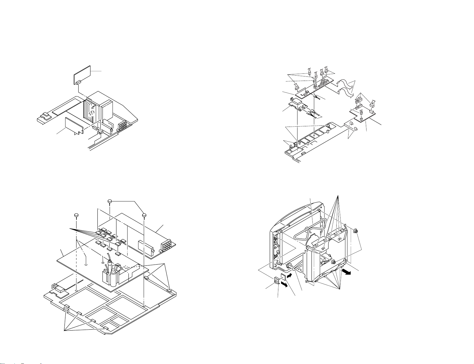
2-8. B3 AND DF BOARDS REMOVAL 2-10. H5 AND K BOARDS REMOVAL
1 B3 board
2 DF board
2Five screws (+BVTP 3×12)
4A Board
3Three claws
5Four screws
(+BVTP 3×12)
1Four connectors
7D Board
6Four claws
$ Two claws
% K board
# One connector
7 One connector
1 Two connectors
" Three connectors
5 Three connectors
9 Screw (+BVTP 3 × 12)
! H5 board
3 F1 board
8 Two claws
2 Two claws
4 Two flat cable
6 Two connectors
5 DGC
3 Seven clamps
1 Four nuts
2 CRT shield
4 Seven clamps
6 DGC
9 H6 board
8 H6 blacket
7 Claw
– 17 –
2-9. A AND D BOARDS REMOVAL
2-11. DGC REMOVAL
KV-LX34M50
RM-871
Page 18
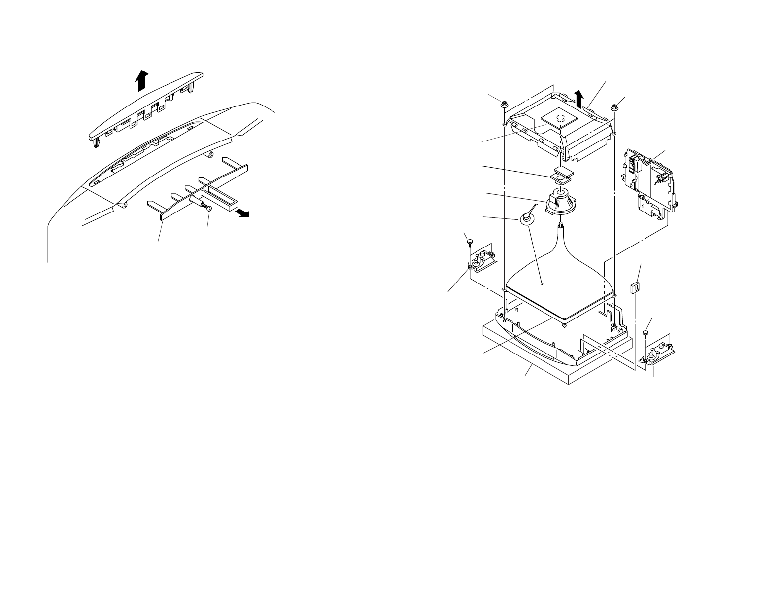
KV -LX34M50
2 Holder panel
1 Loosen screw (+BV 3 × 25)
3 Switch block top
6 Two nuts (special CRT)
8 C1 board
9 Neck assy
! Deflection yoke
4 Anode cap
Two screws
(waher head +P4 × 16)
2 Speaker block assy (L)
" Picture tube
Cushion
2 Speaker block assy (R)
3 H6 block assy
Two screws
(washer head +P 4 × 16)
6 Two nuts (special CRT)
5 Chassis assy
7 DGC with CRT shield
1
1
2-12. SWITCH BLOCK REMOVAL
– 18 –
2-13. PICTURE TUBE REMOVAL
RM-871
Page 19

•REMOVAL OF ANODE-CAP
a
a
b
b
c
Anode button
•HOW TO HANDLE AN ANODE-CAP
NOTE : After removing the anode, short circuit the anode of the picture tube and the
anode cap to the metal chassis, CRT shield or carbon paint on the CRT.
•REMOVING PROCEDURES
1 Turn up one side of the rubber cap in the direction indicated by the arrow a.
– 19 –
2 Using a thumb pull up the rubber cap firmly in the direction indicated by the arrow b.
1 Do not damage the surface of anode-caps with sharp shaped objects.
2 Do not press the rubber too hard so as not to damage the inside of anode-caps.
A metal fitting called the shatter-hook terminal is built into the rubber.
3 Do not turn the foot of rubber over too hard.
The shatter-hook terminal will stick out or damage the rubber.
3 When one side of the rubber cap is separated from the anode button, the anode-cap
can be removed by turning up the rubber cap and pulling it up in the direction of the
arrow c.
KV-LX34M50
RM-871
Page 20

KV -LX34M50
RM-871
SECTION 3
SELF DIAGNOSIS FUNCTION
When turning on the TV, a self diagnosis function is executed.
If no acknowledgement is returned from a device which is turned "ON", the device has a problem.
In this case, one of the LED's responding to the problem device will flicker a defined number of times.
The flickering frequency responding to each failed device is shown below.
Board name
Ref. No.
Device
Flickering Frequency
All the devices are checked one after another from the left of the table.
If an error is found, the responding LED will start flickering.
So, if more than 1 device has failed, only the one on the left side will flicker.
A Board
IC003
NONVOLATILE
MEMORY
1
A Board
IC1201
AV SWITCH
(CXA1855S)
2
A Board
IC104
MAIN Y/C
(CXA2050S)
3
A Board
IC206
SURROUND
PROCESSOR
(TDA8424)
6
– 20 –
Page 21

SECTION 4
SET-UP ADJUSTMENTS
KV-LX34M50
RM-871
• The following adjustments should be made when a complete
realignment is required or a new picture tube is installed.
• These adjustments should be performed with rated power
supply voltage unless otherwise noted.
Controls and switches should be set as follows unless otherwise noted:
PICTURE control........................................................... normal
BRIGHTNESS control................................................... normal
.................................................................................................................................................................................................................................
Preparation :
• In order to reduce the influence of geomagnetism on the set's
picture tube, face it east or west.
• Switch on the set's power and degauss with the degausser.
Perform the adjustments in the following order :
1. Beam Landing
2. Convergence
3. Focus
4. White Balance
Note : Test Equipment Required.
1. Color-bar/Pattern Generator
2. Degausser
3. Oscilloscope
Purity control
4-1. BEAM LANDING
1. Position neck assy as shown in Fig4-1.
2. Input a white signal with the pattern generator.
Contrast
Brightness
3. Set the pattern generator raster signal to a green raster.
4. Move the deflection yoke to the rear and adjust with the purity
control so that the green is at the center and the blue and the red
take up equally sized areas on each side.
(See Figures 4-2 through 4-4.)
5. Move the deflection yoke forward and adjust so that the entire
screen is green. (See Figure 4-2.)
6. Switch the raster signal to blue, then to red and verify the
condition.
7. When the position of the deflection yoke has been decided,
fasten the deflection yoke with the screws and DY spacers.
8. If the beam does not land correctly in all the corners, use a
magnet to adjust it.
(See Figure 4-5.)
Neck assy
}
normal
Fig. 4-3
Red
Green
Fig. 4-4
Purity control
corrects this area.
b
c
Deflection yoke positioning
corrects these areas.
a
d
Blue
Disk magnets or rotatable
disk magnets correct these
areas (a-d).
Behind the G1 edge
G2G1 G3
Fig. 4-1 Fig. 4-2
b
c
a
d
Fig. 4-5
– 21 –
Page 22

KV -LX34M50
RM-871
4-2. CONVERGENCE
Preparation :
• Before starting this adjustment, adjust the focus, horizontal size
and vertical size.
• Minimize the brightness setting.
• Provide dot pattern.
(1) Horizontal and Vertical Static Convergence
Center dot
R G B
H. STAT VR
R
G
B
V. STAT
Magnet
• Operation of V.STAT magnet.
If the V.STAT magnet is moved in the direction of the a and
b arrows, the red, green and blue dots move as shown
below.
1
2
a
bb
a
ab
B
GG
R
R G B
B
R
a
RV702
H. STAT
RV701
SCREEN (G2)
C Board
1. (Moving horizontally), adjust the H.STAT control so that the
red, green and blue dots are on top of each other at the center of
the screen.
2. (Moving vertically), adjust the V.STAT magnet so that the red,
green and blue dots are on top of each other at the center of the
screen.
3. If the red, green and blue dots cannot come together at the center
of the screen, adjust the convergence with the H.ST AT variable
resistor and the V.STAT magnet in the manner given below.
(In this case, the H.STAT variable resistor and the V.STAT
magnet influence each other, so be sure to perform adjustments
while tracking.)
3
b
b
a
b
a
R
G
b
B G R
b
B
G
B
• Operation of BMC (Hexapole) magnet.
If the red, green and blue dots are not balanced or aligned, then
use the BMC magnet to adjust in the manner described below.
RG B
RGB R GB
R
– 22 –
R
B
G
RGB
G
R
B
Page 23

KV-LX34M50
RM-871
• Y separation axis correction magnet adjustment.
1. Receive the cross-hatch signal and adjust [PICTURE] to [MIN]
and [BRIGHTNESS] to [STANDARD] .
2. Adjust the Y separation axis correction magnet on the neck
assembly so that the horizontal lines at the top and bottom of
the screen are straight.
(2) Dynamic Convergence Adjustment
Preparation:
• Before starting this adjustment, adjust the horizontal static
convergence and the vertical static convergence
1. Slightly loosen the deflection yoke screws.
2. Remove the deflection yoke spacer.
Neck assy Neck assy
VM board
Blue
Red
VM board
Red
Blue
Note:
1. The Red and Blue magnets should be equally far from
the horizontal center line.
2. Do not separate the Red and Blue magnets too far.
(Less than 8 mm)
3. Move the deflection yoke as shown in the figure below and
optimize the convergence.
4. Tighten the deflection yoke screws.
5. Install the deflection yoke spacer.
R G B
B G R
R
G
B
B
G
R
B G R
R G B
R G B
B G R
B
G
R
B G R
R
G
B
R G B
– 23 –
Page 24

KV -LX34M50
RM-871
(3) Screen-corner Convergence
ba
a-d : screen-corner
misconvergence
cd
Fix a Permalloy assy corresponding to the misconverged
areas.
a
b
4-4. G2 (SCREEN) AND WHITE BALANCE
ADJUSTMENTS
a. SOME ITEMS OF ADJUSTMENT
Adjustment
Item
number
37
39
3A
3B
3C
item
SBR
GDR
BDR
GCF
BCF
b. ENTERING SERVICE MODE
With the unit on standby
↓
[DISPLAY]
↓
[5]
↓
VOL (+)
↓
[POWER]
Standard DATA
50Hz 60HZ
24 24
1D
20
07
08
SUBBRIGHTNESS
G. Drive
B. Drive
G. Cut-off
B. Cut-off
Note
d
Permalloy assembly
c
4-3. FOCUS ADJUSTMENT
Adjust FOCUS control on the flyback transformer for the best
focus.
c. METHOD OF CANCELLATION FROM SERVICE
MODE
Set the standby condition (Press [POWER] button on the commander),
then press [POWER] button again, hereupon it becomes TV mode.
d. METHOD OF WRITE INTO MEMORY
1) Set to Service Mode.
2) Press [1] (UP) and [4] (DOWN), select an item of adjustment.
3) Press [MUTING] button and it will indicate WRITE on the screen.
4) Press [0] button to write into memory.
Focus
FLYBACK TRANSFORMER (T801)
– 24 –
Page 25

KV-LX34M50
RM-871
e. MEMORY WRITE CONFIRMATION METHOD
1) After adjustment, pull out the plug from AC outlet, and then
plug into AC outlet again.
2) Turn the power switch ON and set to Service Mode.
3) Call the adjusted items again to confirm adjustments were made.
DATA
LCP
09
Adjustment Item
Item number
SERVICE07
50
[1], [4] Select the adjustment item.
↓
[3], [6] Raise/lower the data value.
↓
[MUTING] Writes.
↓
[0] Executes the writing.
2. WHITE BALANCE ADJUSTMENTS
1) Set to Service Mode.
2) Input white raster signal.
3) Set the PICTURE to minimum.
4) Select 37 SBR with
minimum with
5) Select 3B GCF and 3C BCF with
level with
6) Set the PICTURE to maximum.
7) Select 39 GDR and 3A BDR with [1] and [4], and adjust the
level with
8) Write into the memory by pressing
3. SUB BRIGHT ADJUSTMENT
1) Set to service mode.
2) Input a staircase signal of black to white from the pattern generator.
3) BRIGHTNESS ....50%.
PICTURE ............minimum
4) Select 37 SBR with [1] and [4], and adjust SBR level with [3]
and [6] so that the second stripe from the right is dimly lit.
[3] and [6] for the best white balance.
[3] and [6] for the best white balance.
White
[1] and [4], and then set the level to
[3] and [6].
[1] and [4] and adjust the
[MUTING] then [0].
1. G2 (SCREEN) ADJUSTMENT (RV701)
1) Set the PICTURE and BRIGHTNESS to normal.
2) Put to VIDEO input mode without signals.
3) Set to Service Mode.
4) Change item number 8E BLU data from "01" to "00"
(To turn off Blue Back).
5) Press
6) Connect R, G and B of the C board cathode to the oscilloscope.
7) Adjust G2 (RV701) volume to the value below.
8) Re-set item number 8E BLU data from "00" back to "01".
9) Press
[MUTING] and [0] to write the data into the memory.
175 V ±2(VDC)
0 V
[MUTING] and [0] to write the data into the memory.
second from the right
Black
– 25 –
Page 26

KV -LX34M50
RM-871
CIRCUIT ADJUSTMENTS
5-1. ADJUSTMENTS WITH COMMANDER
Service adjustments are made with the RM-871 that comes with
this unit.
Entering service mode
With the unit on standby
↓
[DISPLAY]
↓
5
↓
VOL (+)
↓
[POWER]
This operation sequence puts the unit into service mode.
SECTION 5
1, 4 Select the adjustment item.
↓
3, 6 Raise/lower the data value.
↓
[MUTING] Writes.
↓
- Executes the writing.
7, - All the data becomes the values in memory.
8, - All user control goes to the standard state.
5, - Service data initialization (Be sure not to use
usually.)
2, - Write 50Hz adjustment data to 60Hz, or vice
versa.
GAME
DISPLAY
MUTING
REVEAL
VIDEO
A/B
HOLD
ENLARGE
TEXT TV
2
1
5
4
8
7
JUMP
0
TV/VIDEO
PIP
TEXT
BASSO
SWAPFREEZE
PIP PROGR
ENTER
WAKE UPPOWER
SLEEP
INDEX
TEXT CLR
VOL PROGR
POWER
3
6
9
MENU
+
-
PIP
PROGR
INDEX
The screen display is :
Adjustment item
Item number
00 VSH 1F SERVICE 50
XXX 00 00 00 20V2 1C
SOFTWARE VERSION
DATA
H SYNC COUNTEROEM CODE
Mode
Depends on the signals
PAL, SECAM : 50
NTSC : 60
TV
RM-871
– 26 –
Page 27

5-2. ADJUSTMENT METHOD
Item Number 00
This explanation uses V-Position as an example.
1. Select 00 VSH with the 1 and 4 buttons.
2. Raise/lower the data with the 3 and 6 buttons.
3. Select the optimum state. (The standard is 1F for P AL reception.)
4. Write with the
WRITE.)
5. Execute the writing with the - button. (The WRITE
display will be changed back to SERVICE.)
00
[MUTING] button. (The display changes to
SERVICE 50
1FVSH
Data adjusted with
[3] and [6] buttons.
Item selected with
[1] and [4] buttons.
KV-LX34M50
Use the same method for Items Number 00-99. Use 1 and 4 to
select the adjustment item, use 3 and 6 to adjust, write with
[MUTING], then execute the write with -.
Note : 1. For adjustment items that have different standard data
between 50Hz or 60Hz and normal or wide, be sure to
use the respective input signal while adjusting.
2. In
[WRITE], the data for all items are written into memory
together.
RM-871
1FVSH00
Written with [MUTING]
1FVSH00
Write executed with [0]
WRITE 50
WRITE 50
The display change from
SERVICE to WRITE.
The WRITE display
then changes back to
SERVICE.
– 27 –
Page 28

KV -LX34M50
RM-871
Adjustment Item Table
Item Adjustment Data Standard
number Item range data
00 VSH 00-3F 1F V Position CXA2050S
01 VSZ 00-3F 1F V Size (Y/C/J)
02 HSH 00-0F 07 H Position
03 HSZ 00-3F 1F H Size
04 SCR 00-0F 07 S Correction
05 VLN 00-0F 07 V Linearity
06 PAP 00-3F 1F Pin Comp
07 PPH 00-0F 07 Pin Phase
08 UCP 00-0F 07 Up Corner Pin
09 LCP 00-0F 07 Low Corner Pin
0A BOW 00-0F 07 AFC-Bow
0B ANG 00-0F 07 AFC-Angle
0C V AP 00-3F 2F V Aspect
0D VSC 00-3F 1F V Scroll
0E ULN 00-0F 00 UP V Linearity
0F LLN 00-0F 00 LOW V Linearity
10 EHH 00-03 00 EHT-H
11 EHV 00-03 01 EHT-V
12 HBS 00-01 01 H Blk Wid. ON/OFF
13 LBK 00-0F 0F L Blk Width
14 RBK 00-0F 0F R Blk Width
15 JSW 00-01 00 Jump ON/OFF Sw
16 VBW 00-03 02 V Blk Wid. Con.
17 AFC 00-03 01 AFC-Mode
18 FHH 00-01 00 FH-HI
19 VFQ 00-03 00 V-Freq
1A VOF 00-01 00 V OFF
1B VMD 00-01 00 CD-Mode 2
1C CMD 00-01 00 CD-Mode
1D ITL 00-03 00 Inter Iace
1E ZSW 00-01 00 ZOOM SW
1F POV 00-03 03 Pre-Over
20 CT1 00-01 01 C-Trap(NTSC)
21 CT2 00-01 01 C-Trap(PAL)
22 CF0 00-0F 07 C-Trap f0 Adj
23 SF0 00-01 01 Sharpness f0 Adi
24 TOT 00-01 01 TOT Filter SW
25 CSW 00-03 00 Color SW
26 XTL 00-03 00 Xtal
27 CV1 00-01 01 CV/YC Select(NTSC)
28 CV2 00-01 01 CV/YC Select(PAL)
29 VM 00-01 01 VM ON/OFF
2A YVM 00-01 00 YSI/VM SW(0:YSI)
2B DPC 00-01 01 D-Pic ON/OFF
2C DCO 00-01 01 Dynamic Color
2D GMM 00-03 01 Gamma
2E DTR 00-01 01 DC-Tran
2F DL1 00-07 01 Delay Ctrl.(PAL)
30 DL2 00-07 03 Delay Ctrl.(NTSC)
31 DL3 00-07 03 Delay Ctrl.(SECAM)
32 SCN 00-0F 09 Sub-Contrast
33 SC1 00-0F 0B Sub-Color (Others)
34 SC2 00-0F 0A Sub-Color (NTSC)
35 SH1 00-0F 0A Sub-Hue (TV)
36 SH2 00-0F 0A Sub-Hue (Video)
37 SBR 00-3F 17 Sub-Bright
38 SSH 00-07 04 Sub-Sharpness
39 GDR 00-3F 2C G-Drive
3A BDR 00-3F 2C B-Drive
3B GCF 00-0F 07 G-Cutoff
Note Device
Note: Bold items are fixed data.
– 28 –
Page 29

Adjustment Item Table
KV-LX34M50
RM-871
Item Adjustment Data Standard
number Item range data
3C BCF 00-0F 07 B-Cutoff CXA2050S
3D RPO 00-03 01 Ref-Position (Y/C/J)
3E PON 00-01 01 Pic-ON
3F RON 00-01 01 R ON
40 GON 00-01 01 G ON
41 BON 00-01 01 B ON
42 AKF 00-01 00 AKB ON/OFF SW
43 ESY 00-01 00 Ext Sync Select
44 AGG 00-01 00 Aging Mode ON/OFF
45 ABL 00-01 01 ABL Pic/Pic&Brt SW(0:Pic only)
46 LIM 00-01 00 RGB Limit ON/OFF(0:ON)
47 PB 00-01 01 Picture Booster TDA9170
48 BOF 00-01 01 Black Offset (Picture
49 UVG 00-3F 1F User Var. Gamma Improve)
4A ADG 00-3F 1F Adaptive Gamma
4B NLA 00-3F 0F Non-Iinear Amp
4C WDS 00-02 00 Window Select
4D LST 00-0F 07 Window Line Start
4E LSP 00-0F 07 Window Line Stop
4F FST 00-0F 07 Window Field Start
50 FSP 00-0F 07 Window Field Stop
51 VA 00-01 01 V Aperture on/off CXA1315
52 VAW 00-03 02 V Aperture white (V-AP)
53 VAB 00-03 02 V Aperture black
54 VAC 00-0F 03 V Aperture core
55 SHP 00-3F 0F Sharpness CXA1315
56 VML 00-3F 29 VM Limitter (LTI)
57 COR 00-3F 17 Coreing
58 DOF 00-3F 15 DSC Offset
59 DGA 00-3F 1F DSC Gain
5A DLT 00-01 01 Delay Time
5B SDL 00-0F 01 SEL Pin Delay SDA9189X
5C POH 00-FF 14 H Position(MSB8bit) (PinP)
5D POV 00-FF 27 V Position
5E PMD 00-1F 00 Pinp Display Mode
5F WRP 00-0F 00 Write Position
60 HDL 00-1F 0B HSI Delay
61 AMS 00-01 00 Decimation Filter
62 VDL 00-1F 0B VSI Delay
63 VSP 00-1F 0D VSP Delay
64 CON 00-0F 06 Contrast
65 FRY 00-0F 09 Frame Y
66 FRV 00-0F 00 Frame V
67 FRU 00-0F 00 Frame U
68 INF 00-01 01 Inner Frame
69 FWV 00-03 02 Frame Width V
6A FWH 00-07 07 Frame Width H
6B PLL 00-03 02 PLL Loop Filter
6C PDV 00-0F 00 Pedestal V
6D PDU 00-0F 00 Pedestal U
6E DAT 00-01 00 DAC Stream Control
6F DAN 00-01 00 DAC Control
70 WIP 00-01 00 Wipe on/off
71 WSP 00-03 00 Wipe Speed
Note Device
Note: Bold items are fixed data.
– 29 –
Page 30

KV -LX34M50
RM-871
Adjustment Item Table
Item Adjustment Data Standard
number Item range data
72 FAW 00-FF 08 NICAM FAW Thresh MSP3410
73 CTM 00-FF 08 NICAM Error Bit(MONO) (Audio Stereo
74 CTN 00-FF 50 NICAM Error Bit(NICAM) Decoder)
75 WCD 00-FF 0A W.G.Change Data
76 WST 00-FF 15 W.G.STEREO Threshold
77 WTM 00-FF 50 W.G.Timer
78 WBT 00-FF EA W.G.BILINGUAL Threshold
79 ACG 00-01 01 AGC AUTO/CONST.
7A CDB 00-3F 28 AGC GAIN CONST.
7B FGP 00-7F 24 FM(BG,I,DK)Prescale
7C FMP 00-7F 40 FM(M) Prescale
7D WGP 00-7F 3C W.G.Prescale
7E NIP 00-7F 7F NICAM Prescale
7F CRM 00-01 00 Carrier Mute
80 CML 00-03 00 Carrier Mute Level
81 ACO 00-01 01 Audio Clock Out
82 WAC 00-0F 01 W.G Agreement count
83 DLY 00-FF 30 Stereo Search Delay
84 DLG 00-FF 10 W.G. Search Delay
85 TXP 00-0F 0E Text Picture cont. SAA 5281
86 MXP 00-0F 0F Text Mix mode Pic.
87 BB1 00-3F 1D BBE control High CXA1315
88 BB2 00-3F 1D BBE control Middle (BBE)
89 BB3 00-3F 28 BBE control Low
8A ATW 00-03 00 Auto Wide Ident Speed CXP5068
8B BKP 00-FF 00 Blk off Picture CXP85340
8C OSH 00-3F 0E OSD Position H (MICRO
8D ODL 00-FF 10 Power On Delay CONTROLLER)
8E BLU 00-01 01 Blue Back on/off
8F ROC 00-0F 08 N/S Center Vol.
90 ROS 00-07 07 User Step
91 DKS 00-01 00 D/K Stereo Search
92 MUT 00-01 01 No Sync. Mute
93 DID 00-01 00 Disable Degauss
94 DWZ 00-01 00 Disable Widezoom
95 BCS 00-01 00 BASS Center Shift
96 BVS 00-01 00 Basso Volume Shift
97 WBS 00-03 00 Woofer Off Bass Shift
98 OP0 00-FF 01 Option 0
99 OP1 00-FF 3E Option 1
NOTE:
• Bold items are fixed data.
...
• 50
50Hz data, 60
• Standard data listed on the Adjustment Item Table are reference values, therefore if may be different for each model and
mode.
...
60Hz data
Note Device
– 30 –
Page 31

ITEM INFORMATION.
No.98 OP0
Item
KV-LX34M50
No.99 OP1
Item
KV-LX34M50
• 98 OP0, 99 OP1
Fastext : 0 → Automatic mode, 1 → Fastext mode
B/G only : 0 → Multi system, 1 → B/G system only
Comb type : 0 → Glass comb filter, 1 → Digital comb filter
Wide : 0 → 4:3 model, 1 → 16:9 model
–
0
Wide
0
–
0
Woofer
1
Tilt
KV-LX34M50
RM-871
–
0
1
–
0
VM
1
–
0
Comb type
1
–
0
Comb filter
1
–
0
SECAM
1
Fastext
0
B/G only
0
– 31 –
Page 32

KV -LX34M50
VB1 VB2 VB3 VB4
VB1 = VB2 = VB3 = VB4
RM-871
5-3. PICTURE QUALITY ADJUSTMENTS
SUB CONTRAST ADJUSTMENT (SCN)
1. Receive a PAL color-bar.
2. Set service item 40 GON and 41 BON to data "00". Set the
PICTURE 100%, BRIGHTNESS 50% and COLOR MIN.
3. Connect an oscilloscope to the pin 6 (R OUT) of CN117, A
board.
4. Set to Service Mode and select 32 SCN using 1 and 4 of the
commander, then adjust to 2.25 ± 0.05V using 3 and 6.
5. Press
6. Receive a NTSC color-bar and adjust 32 SCN as step 2 to 5.
7. Set service item 40 GON and 41 BON to data "01".
[MUTING] → - of the commander to write the data.
White
2.25 ± 0.05 Vp-p
Black
SUB HUE ADJUSTMENT (SH1 & SH2)
1. Receive a NTSC 3.58 color-bar.
2. Set the following condition:
PICTURE 100%, BRIGHTNESS 50%, COLOR 50%, HUE 0%
3. Connect an oscilloscope to the pin 4 (B OUT) of CN117, A
board.
4. Select 36 SH2 with 1 and 4 of the commander by setting to
Service Mode and adjust to VB1=VB2=VB3=VB4 with 3 and
6.
5. Write the data 1 step down from adjusted data.
6. Write data as below onto 35 SH1: 35 SH1 = 36 SH2 (Written
data) - 3
SUB COLOR ADJUSTMENT (SC1 & SC2)
1. Input a PAL color-bar.
2. Set service item 4B NLA to data "00".
Set to the following condition:
PICTURE 100%, BRIGHTNESS 50%, COLOR 50%
Remark: Adjustment must be done with both P1 & B1 boards
fitted.
3. Connect an oscilloscope to the pin 4 (B OUT) of CN117, A
board.
4. Set to Service Mode and select 33 SC1 with 1 and 4 of the
commander then adjust to VB2=VB3=VB4 with 3 and 6.
5. Press [MUTING] → - of the commander to write the data.
6. Write 34 SC2 data same as 33 SC1 data.
7. Set service item 4B NLA to data "05" and write the data.
5-4. DISPLAY POSITION ADJUSTMENT
PIP POSITION (POH, POV)
1. Receive a PAL color-bar.
2. Set the PIP picture by pressing PIP button on the commander.
3. Set to Service Mode.
4. Select 5C POH with the 1 and 4 on the commander and set
the data "14" with 3 and 6.
5. Select 5D POV to set the data "27"
6. Press [MUTING] → - on the commander to write the data.
7. Check by changing the PIP position using the on-screen menu.
VB1 VB2 VB3 VB4
VB2 = VB3 = VB4
– 32 –
Page 33

KV-LX34M50
RM-871
KV -LX34M50
RM-871
5-5. A BOARD ADJUSTMENT AFTER IC003
(MEMORY) REPLACEMENT
1. Enter to Service Mode.
2. Press commander buttons 5 and - (Data Initialize), and 2
and - (Data Copy) to initialize the data.
3. Call each item number and check if the respective screen shows
the normal picture.
In cases where items are not well adjusted, rectify the items
with fine adjustment.
Write the data per each item number (
4. Select item numbers 98 OP0 and 99 OP1 and respectively set
the bit per model with command buttons 3 and 6.
5. Press commander buttons 8 and - (Test Normal) to return
to the data that was set on the shipment from the factory.
(This will also cancel Service Mode.)
[MUTING] +-).
5-6. PICTURE DISTORTION ADJUSTMENT
Item Number 00 – 0B
00 VSH(V POSITION)
01 VSZ(V SIZE)
02 HSH(H POSITION)
03 HSZ (H SIZE)
04 SCR(VERTICAL S-Correction)
MEMO
○○○○○○○○○○○○○○○○○○○○○○○○○○○○○○○○○○○○○○○○○○○○○○○○○○○○○○○○○○○○○○○
○○○○○○○○○○○○○○○○○○○○○○○○○○○○○○○○○○○○○○○○○○○○○○○○○○○○○○○○○○○○○○○
○○○○○○○○○○○○○○○○○○○○○○○○○○○○○○○○○○○○○○○○○○○○○○○○○○○○○○○○○○○○○○○
○○○○○○○○○○○○○○○○○○○○○○○○○○○○○○○○○○○○○○○○○○○○○○○○○○○○○○○○○○○○○○○
○○○○○○○○○○○○○○○○○○○○○○○○○○○○○○○○○○○○○○○○○○○○○○○○○○○○○○○○○○○○○○○
○○○○○○○○○○○○○○○○○○○○○○○○○○○○○○○○○○○○○○○○○○○○○○○○○○○○○○○○○○○○○○○
○○○○○○○○○○○○○○○○○○○○○○○○○○○○○○○○○○○○○○○○○○○○○○○○○○○○○○○○○○○○○○○
○○○○○○○○○○○○○○○○○○○○○○○○○○○○○○○○○○○○○○○○○○○○○○○○○○○○○○○○○○○○○○○
○○○○○○○○○○○○○○○○○○○○○○○○○○○○○○○○○○○○○○○○○○○○○○○○○○○○○○○○○○○○○○○
○○○○○○○○○○○○○○○○○○○○○○○○○○○○○○○○○○○○○○○○○○○○○○○○○○○○○○○○○○○○○○○
○○○○○○○○○○○○○○○○○○○○○○○○○○○○○○○○○○○○○○○○○○○○○○○○○○○○○○○○○○○○○○○
○○○○○○○○○○○○○○○○○○○○○○○○○○○○○○○○○○○○○○○○○○○○○○○○○○○○○○○○○○○○○○○
○○○○○○○○○○○○○○○○○○○○○○○○○○○○○○○○○○○○○○○○○○○○○○○○○○○○○○○○○○○○○○○
○○○○○○○○○○○○○○○○○○○○○○○○○○○○○○○○○○○○○○○○○○○○○○○○○○○○○○○○○○○○○○○
○○○○○○○○○○○○○○○○○○○○○○○○○○○○○○○○○○○○○○○○○○○○○○○○○○○○○○○○○○○○○○○
○○○○○○○○○○○○○○○○○○○○○○○○○○○○○○○○○○○○○○○○○○○○○○○○○○○○○○○○○○○○○○○
05 VLN(V LINEARITY)
06 PAP (PIN AMP)
07 PPH(PIN PHASE)
08 UCP(Upper Corner Pin)
09 LCP(Lower Corner Pin)
0A VBOW(AFC.BOW)
○○○○○○○○○○○○○○○○○○○○○○○○○○○○○○○○○○○○○○○○○○○○○○○○○○○○○○○○○○○○○○○
○○○○○○○○○○○○○○○○○○○○○○○○○○○○○○○○○○○○○○○○○○○○○○○○○○○○○○○○○○○○○○○
○○○○○○○○○○○○○○○○○○○○○○○○○○○○○○○○○○○○○○○○○○○○○○○○○○○○○○○○○○○○○○○
○○○○○○○○○○○○○○○○○○○○○○○○○○○○○○○○○○○○○○○○○○○○○○○○○○○○○○○○○○○○○○○
○○○○○○○○○○○○○○○○○○○○○○○○○○○○○○○○○○○○○○○○○○○○○○○○○○○○○○○○○○○○○○○
○○○○○○○○○○○○○○○○○○○○○○○○○○○○○○○○○○○○○○○○○○○○○○○○○○○○○○○○○○○○○○○
○○○○○○○○○○○○○○○○○○○○○○○○○○○○○○○○○○○○○○○○○○○○○○○○○○○○○○○○○○○○○○○
○○○○○○○○○○○○○○○○○○○○○○○○○○○○○○○○○○○○○○○○○○○○○○○○○○○○○○○○○○○○○○○
○○○○○○○○○○○○○○○○○○○○○○○○○○○○○○○○○○○○○○○○○○○○○○○○○○○○○○○○○○○○○○○
○○○○○○○○○○○○○○○○○○○○○○○○○○○○○○○○○○○○○○○○○○○○○○○○○○○○○○○○○○○○○○○
○○○○○○○○○○○○○○○○○○○○○○○○○○○○○○○○○○○○○○○○○○○○○○○○○○○○○○○○○○○○○○○
○○○○○○○○○○○○○○○○○○○○○○○○○○○○○○○○○○○○○○○○○○○○○○○○○○○○○○○○○○○○○○○
○○○○○○○○○○○○○○○○○○○○○○○○○○○○○○○○○○○○○○○○○○○○○○○○○○○○○○○○○○○○○○○
○○○○○○○○○○○○○○○○○○○○○○○○○○○○○○○○○○○○○○○○○○○○○○○○○○○○○○○○○○○○○○○
○○○○○○○○○○○○○○○○○○○○○○○○○○○○○○○○○○○○○○○○○○○○○○○○○○○○○○○○○○○○○○○
○○○○○○○○○○○○○○○○○○○○○○○○○○○○○○○○○○○○○○○○○○○○○○○○○○○○○○○○○○○○○○○
○○○○○○○○○○○○○○○○○○○○○○○○○○○○○○○○○○○○○○○○○○○○○○○○○○○○○○○○○○○○○○○
0B VAG(AFC.ANGLE)
– 33 –
○○○○○○○○○○○○○○○○○○○○○○○○○○○○○○○○○○○○○○○○○○○○○○○○○○○○○○○○○○○○○○○
○○○○○○○○○○○○○○○○○○○○○○○○○○○○○○○○○○○○○○○○○○○○○○○○○○○○○○○○○○○○○○○
○○○○○○○○○○○○○○○○○○○○○○○○○○○○○○○○○○○○○○○○○○○○○○○○○○○○○○○○○○○○○○○
○○○○○○○○○○○○○○○○○○○○○○○○○○○○○○○○○○○○○○○○○○○○○○○○○○○○○○○○○○○○○○○
○○○○○○○○○○○○○○○○○○○○○○○○○○○○○○○○○○○○○○○○○○○○○○○○○○○○○○○○○○○○○○○
○○○○○○○○○○○○○○○○○○○○○○○○○○○○○○○○○○○○○○○○○○○○○○○○○○○○○○○○○○○○○○○
– 34 –
Page 34

NOTE:
• Items with no part number and no description are not stocked because they
are seldom required for routine service.
• The construction parts of an assembled
part are indicated with a collation
number in the remark column.
7-1. PICTURE TUBE
p : +BV 3 × 25 7-685-152-19
4 : +BVTP 3 × 12 7-685-648-79
¢ : +BVTP 4 × 12 7-685-661-14
r : +BVTP 4 × 16 7-685-663-71
30
SECTION 7
EXPLODED VIEWS
• Items marked " ∗ " are not stocked since
they are seldom required for routine
service. Some delay should be
anticipated when ordering these items.
25
KV-LX34M50
RM-871
The components identified by
shading and mark ! are critical
for safety.
Replace only with part number
specified.
29
11
12
17
23
24
21
20
31
16
2
13
19
18
3
32
5
22
4
26
34
28
26
24
27
6
13
7
3
14
15
8
5
4
1
9
10
33
REF. NO. PART NO. DESCRIPTION REMARK REF. NO. PART NO. DESCRIPTION REMARK
1 4-060-999-21 DOOR, CONTROL
2 X-4035-1 10-2 BEZNET ASSY 1, 6-10
3 1-505-489-11 SPEAKER (5CM)
4 4-374-745-21 CUSHION (A)
5 1-503-902-11 SPEAKER (15X6.5 CM)
6 4-061-002-01 PANEL, ORNAMENTAL(L)
7 4-061-003-01 PANEL, ORNAMENTAL(R)
8 4-047-464-01 CATCHER, PUSH
9 4-061-001-01 BUTTON, POWER
10 4-036-405-11 SPRING, COMPRESSION
11 1-475-454-11 SWITCH BLOCK, TOP
12 * 4-061-022-01 HOLDER, PANEL
13 4-302-447-03 SCREW (WASHER HEAD) (+P 4X16)
14 * A-1372-424-A H6 BOARD, COMPLETE
15 * 4-061-017-01 BRACKET, H6
16 ! 8-733-746-05 PICTURE TUBE (A80JYV51X)
17 * 4-047-349-01 HOLDER, HV CABLE
18 4-060-267-01 SPACER, DY
19 8-451-482-31 DEFLECTION YOKE (Y34FXA2-S)
20 1-452-616-11 NECK ASSY, CRT (NA323)
21 * A-1342-408-A VM BOARD, COMPLETE
22 4-376-036-01 SPRING, TENSION
23 * A-1331-780-A C1 BOARD, COMPLETE
24 ! 1-411-132-11 COIL, DEMAGNETIZATION
25 * 4-061-031-01 BRACKET, CONNECTOR
26 4-387-204-01 NUT, SPECIAL, CRT
27 4-385-725-01 SHEET, BLOTTING
28 ! 4-060-998-01 COVER, REAR
29 4-394-044-01 SCREW, STEP HILO TAPPING
30 1-452-032-00 MAGNET, DISC
31 X-4387-214-1 PERMALOY ASSY, CORRECTION
32 * X-4035-154-1 BRACKET (L) ASSY, SP
33 * X-4035-155-1 BRACKET (R) ASSY, SP
34 * X-4035-248-2 COVER ASSY , REAR 28
– 69 –
Page 35

KV -LX34M50
RM-871
7-2. CHASSIS
4 : +BVTP 3 × 12 7-685-648-79
52
53
55
54
67
56
78
68
57
69
77
76
61
58
59
70
60
62
65
66
64
63
71
77
51
72
74
73
51 * A-1372-446-A H5 BOARD, COMPLETE
52 1-782-896-11 CABLE, FLAT
53 * A-1380-572-A K BOARD, COMPLETE
54 * A-1131-317-A B3 BOARD, COMPLETE
55 * A-1195-126-A P1 BOARD, COMPLETE
56 * A-1390-800-A S1 BOARD, COMPLETE
57 * 4-055-142-01 HOLDER, PC BOARD
58 * 4-055-139-01 HOLDER, FBT
59 * A-1190-304-A P2 BOARD, COPMLETE
60 8-598-373-10 TUNER, FSS BTF-FG431
61 ! 4-022-115-12 HOLDER, AC CORD
62 ! 1-777-954-11 CORD, POWER (WITH CONNECTOR) 2.5A/250V
63 * 1-555-110-00 CABLE, P-P
64 1-251-447-21 DISTRIBUTOR, RF
65 4-055-141-01 BRACKET, TERMINAL
75
REF. NO. PART NO. DESCRIPTION REMARKREF. NO. PART NO. DESCRIPTION REMARK
66 4-382-854-11 SCREW (M3X10), P, SW (+)
67 * A-1298-501-A A BOARD, COMPLETE
68 4-046-797-01 SCREW (3X12), (+)BVTAP
69 8-598-372-10 TUNER, FSS BTF-FG441
70 ! 1-453-255-11
71 * A-1343-472-A DF BOARD, COMPLETE
72 * 4-055-447-21 SHEET, INSULATING
73 * A-1241-318-A F1 BOARD, COMPLETE
74 * 4-061-020-01 BRACKET, H5
75 * X-4035-156-1 MAIN BRACKET ASSY
76 * A-1346-727-A D BOARD, COMPLETE
77 4-302-428-03 SCREW (WASHER HEAD) (+P 3X12)
78 3-682-057-21 SPACER (SMALL)
TRANSFORMER ASSY , FL YBACK (NX-4122//M3J4)
– 70 –
Page 36

7-3. 3D SPEAKER
¢ : +BVTP 4 × 12 7-685-661-14
r : +BVTP 4 × 16 7-685-663-71
KV-LX34M50
RM-871
101
102
107
103
104
105
106
REF. NO. PART NO. DESCRIPTION REMARK
108
109
110
101 X-4035-173-1 SP BOX(UPPER)(ASSY)
102 * 4-061-013-01 SEAL, BOX
103 1-505-792-11 SPEAKER (16CM)
104 1-900-233-38 CONNECTOR ASSY 2P
105 4-061-009-01 SP BOX (LOWER)
106 4-061-007-01 FOOT
107 * 4-061-014-01 SEAL, DUCT
108 * 4-061-010-01 DUCT
109 * 4-061-015-01 CUSHION, WOOFER
110 4-396-117-01 CUSHION (A)
??? * 4-061-014-11 DUCT, SEAL
??? * 4-063-029-01 CUSHION, 3D BOX
– 71 –
Page 37

KV-LX34M50
RM-871
A
REF. NO. PART NO. DESCRIPTION REMARK REF. NO. PART NO. DESCRIPTION REMARK
NOTE:
The components identified by shading
and mark ! are critical for safety.
Replace only with part number specified.
When indicating parts by reference
number, please include the board name.
SECTION 8
ELECTRICAL PARTS LIST
• Items marked " ∗ " are not stocked since they
are seldom required for routine service.
Some delay should be anticipated when ordering these items.
• All variable and adjustable resistors have
characteristic curve B, unless otherwise
noted.
REF.NO. PART NO. DESCRIPTION REMARKREF.NO. PART NO. DESCRIPTION REMARK
The components identified by shading
and mark ! are critical for safety.
Replace only with part number specified.
• All resistors are in ohms
• F : nonflammable
CAPACITORS
• MF : µF, PF : µµF
COILS
• MMH : mH, UH : µH
* A-1298-501-A A BOARD, COMPLETE
*********************
4-382-854-11 SCREW (M3X10), P, SW (+)
<CAPACITOR>
C001 1-163-011-11 CERAMIC CHIP 0.0015MF 10% 50V
C002 1-126-965-11 ELECT 22MF 20% 50V
C003 1-163-251-11 CERAMIC CHIP 100PF 5% 50V
C004 1-126-961-11 ELECT 2.2MF 20% 50V
C005 1-163-251-11 CERAMIC CHIP 100PF 5% 50V
C006 1-163-251-11 CERAMIC CHIP 100PF 5% 50V
C007 1-126-959-11 ELECT 0.47MF 20% 50V
C008 1-163-251-11 CERAMIC CHIP 100PF 5% 50V
C009 1-163-275-11 CERAMIC CHIP 0.001MF 5% 50V
C010 1-163-037-11 CERAMIC CHIP 0.022MF 10% 50V
C011 1-163-251-11 CERAMIC CHIP 100PF 5% 50V
C012 1-163-251-11 CERAMIC CHIP 100PF 5% 50V
C013 1-163-251-11 CERAMIC CHIP 100PF 5% 50V
C014 1-163-275-11 CERAMIC CHIP 0.001MF 5% 50V
C015 1-101-884-00 CERAMIC 56PF 5% 50V
C016 1-101-884-00 CERAMIC 56PF 5% 50V
C017 1-163-251-11 CERAMIC CHIP 100PF 5% 50V
C018 1-163-099-00 CERAMIC CHIP 18PF 5% 50V
C019 1-163-275-11 CERAMIC CHIP 0.001MF 5% 50V
C020 1-163-259-91 CERAMIC CHIP 220PF 5% 50V
C021 1-163-275-11 CERAMIC CHIP 0.001MF 5% 50V
C022 1-126-968-11 ELECT 100MF 20% 50V
C023 1-163-275-11 CERAMIC CHIP 0.001MF 5% 50V
C024 1-163-259-91 CERAMIC CHIP 220PF 5% 50V
C025 1-163-275-11 CERAMIC CHIP 0.001MF 5% 50V
C026 1-163-251-11 CERAMIC CHIP 100PF 5% 50V
C027 1-163-251-11 CERAMIC CHIP 100PF 5% 50V
C028 1-163-259-91 CERAMIC CHIP 220PF 5% 50V
C029 1-163-259-91 CERAMIC CHIP 220PF 5% 50V
C030 1-163-037-11 CERAMIC CHIP 0.022MF 10% 50V
C031 1-163-243-11 CERAMIC CHIP 47PF 5% 50V
C032 1-163-259-91 CERAMIC CHIP 220PF 5% 50V
C033 1-164-505-11 CERAMIC CHIP 2.2MF 16V
C034 1-164-004-11 CERAMIC CHIP 0.1MF 10% 25V
C035 1-163-009-11 CERAMIC CHIP 0.001MF 10% 50V
C037 1-163-259-91 CERAMIC CHIP 220PF 5% 50V
C038 1-126-968-11 ELECT 100MF 20% 50V
C039 1-163-251-11 CERAMIC CHIP 100PF 5% 50V
C040 1-163-251-11 CERAMIC CHIP 100PF 5% 50V
C041 1-164-004-11 CERAMIC CHIP 0.1MF 10% 25V
C042 1-163-251-11 CERAMIC CHIP 100PF 5% 50V
C043 1-163-251-11 CERAMIC CHIP 100PF 5% 50V
C044 1-163-251-11 CERAMIC CHIP 100PF 5% 50V
C045 1-216-295-91 SHORT 0
C046 1-163-251-11 CERAMIC CHIP 100PF 5% 50V
C048 1-163-251-11 CERAMIC CHIP 100PF 5% 50V
C049 1-163-251-11 CERAMIC CHIP 100PF 5% 50V
C050 1-163-251-11 CERAMIC CHIP 100PF 5% 50V
C051 1-163-251-11 CERAMIC CHIP 100PF 5% 50V
C052 1-164-004-11 CERAMIC CHIP 0.1MF 10% 25V
C053 1-164-004-11 CERAMIC CHIP 0.1MF 10% 25V
C054 1-164-232-11 CERAMIC CHIP 0.01MF 10% 50V
C055 1-126-941-11 ELECT 470MF 20% 16V
C056 1-163-011-11 CERAMIC CHIP 0.0015MF 10% 50V
C057 1-163-001-11 CERAMIC CHIP 220PF 10% 50V
C060 1-126-933-11 ELECT 100MF 20% 16V
C061 1-164-004-11 CERAMIC CHIP 0.1MF 10% 25V
C062 1-164-004-11 CERAMIC CHIP 0.1MF 10% 25V
C063 1-126-933-11 ELECT 100MF 20% 16V
C064 1-163-037-11 CERAMIC CHIP 0.022MF 10% 50V
C065 1-163-259-91 CERAMIC CHIP 220PF 5% 50V
C066 1-163-259-91 CERAMIC CHIP 220PF 5% 50V
C067 1-163-259-91 CERAMIC CHIP 220PF 5% 50V
C068 1-163-259-91 CERAMIC CHIP 220PF 5% 50V
C069 1-163-259-91 CERAMIC CHIP 220PF 5% 50V
C072 1-126-941-11 ELECT 470MF 20% 16V
C074 1-163-001-11 CERAMIC CHIP 220PF 10% 50V
C078 1-126-933-11 ELECT 100MF 20% 16V
C079 1-126-967-11 ELECT 47MF 20% 50V
C080 1-164-232-11 CERAMIC CHIP 0.01MF 10% 50V
C081 1-164-232-11 CERAMIC CHIP 0.01MF 10% 50V
C084 1-164-232-11 CERAMIC CHIP 0.01MF 10% 50V
C085 1-164-232-11 CERAMIC CHIP 0.01MF 10% 50V
C086 1-164-232-11 CERAMIC CHIP 0.01MF 10% 50V
C087 1-164-232-11 CERAMIC CHIP 0.01MF 10% 50V
C088 1-164-232-11 CERAMIC CHIP 0.01MF 10% 50V
C089 1-164-232-11 CERAMIC CHIP 0.01MF 10% 50V
C090 1-104-664-11 ELECT 47MF 20% 25V
C091 1-104-664-11 ELECT 47MF 20% 25V
C093 1-104-664-11 ELECT 47MF 20% 25V
C101 1-126-960-11 ELECT 1MF 20% 50V
C102 1-163-251-11 CERAMIC CHIP 100PF 5% 50V
C103 1-164-161-11 CERAMIC CHIP 0.0022MF 10% 50V
C105 1-164-343-11 CERAMIC CHIP 0.056MF 10% 25V
C106 1-164-232-11 CERAMIC CHIP 0.01MF 10% 50V
C107 1-163-251-11 CERAMIC CHIP 100PF 5% 50V
C108 1-126-942-61 ELECT 1000MF 20% 25V
– 72 –
Page 38

The components identified by shading
and mark ! are critical for safety.
Replace only with part number specified.
KV-LX34M50
RM-871
A
REF. NO. PART NO. DESCRIPTION REMARK
C109 1-163-017-00 CERAMIC CHIP 0.0047MF 10% 50V
C110 1-164-232-11 CERAMIC CHIP 0.01MF 10% 50V
C118 1-126-965-11 ELECT 22MF 20% 50V
C119 1-163-031-11 CERAMIC CHIP 0.01MF 50V
C127 1-164-004-11 CERAMIC CHIP 0.1MF 10% 25V
C128 1-126-963-11 ELECT 4.7MF 20% 50V
C129 1-136-173-00 FILM 0.47MF 5% 50V
C130 1-126-960-11 ELECT 1MF 20% 50V
C133 1-104-664-11 ELECT 47MF 20% 25V
C134 1-164-232-11 CERAMIC CHIP 0.01MF 10% 50V
C135 1-126-959-11 ELECT 0.47MF 20% 50V
C136 1-164-005-11 CERAMIC CHIP 0.47MF 25V
C137 1-163-133-00 CERAMIC CHIP 470PF 5% 50V
C138 1-126-964-11 ELECT 10MF 20% 50V
C139 1-163-231-11 CERAMIC CHIP 15PF 5% 50V
C140 1-126-964-11 ELECT 10MF 20% 50V
C141 1-163-099-00 CERAMIC CHIP 18PF 5% 50V
C142 1-126-959-11 ELECT 0.47MF 20% 50V
C143 1-126-964-11 ELECT 10MF 20% 50V
C145 1-126-964-11 ELECT 10MF 20% 50V
C146 1-163-251-11 CERAMIC CHIP 100PF 5% 50V
C147 1-164-232-11 CERAMIC CHIP 0.01MF 10% 50V
C148 1-164-346-11 CERAMIC CHIP 1MF 16V
C149 1-164-346-11 CERAMIC CHIP 1MF 16V
C150 1-164-346-11 CERAMIC CHIP 1MF 16V
C151 1-164-232-11 CERAMIC CHIP 0.01MF 10% 50V
C152 1-104-664-11 ELECT 47MF 20% 25V
C153 1-164-232-11 CERAMIC CHIP 0.01MF 10% 50V
C154 1-126-961-11 ELECT 2.2MF 20% 50V
C155 1-164-232-11 CERAMIC CHIP 0.01MF 10% 50V
C156 1-163-017-00 CERAMIC CHIP 0.0047MF 10% 50V
C157 1-164-232-11 CERAMIC CHIP 0.01MF 10% 50V
C158 1-164-161-11 CERAMIC CHIP 0.0022MF 10% 50V
C159 1-164-232-11 CERAMIC CHIP 0.01MF 10% 50V
C160 1-164-346-11 CERAMIC CHIP 1MF 16V
C162 1-126-934-11 ELECT 220MF 20% 16V
C163 1-164-346-11 CERAMIC CHIP 1MF 16V
C164 1-137-581-11 FILM 0.1MF 5% 100V
C165 1-164-346-11 CERAMIC CHIP 1MF 16V
C166 1-137-581-11 FILM 0.1MF 5% 100V
C167 1-104-664-11 ELECT 47MF 20% 25V
C168 1-164-232-11 CERAMIC CHIP 0.01MF 10% 50V
C169 1-137-372-11 FILM 0.022MF 5% 50V
C170 1-163-009-11 CERAMIC CHIP 0.001MF 10% 50V
C187 1-137-372-11 FILM 0.022MF 5% 50V
C189 1-126-965-11 ELECT 22MF 20% 50V
C191 1-137-372-11 FILM 0.022MF 5% 50V
C192 1-136-173-00 FILM 0.47MF 5% 50V
C195 1-136-173-00 FILM 0.47MF 5% 50V
C198 1-163-009-11 CERAMIC CHIP 0.001MF 10% 50V
C199 1-164-004-11 CERAMIC CHIP 0.1MF 10% 25V
C200 1-164-232-11 CERAMIC CHIP 0.01MF 10% 50V
C206 1-164-004-11 CERAMIC CHIP 0.1MF 10% 25V
C207 1-164-004-11 CERAMIC CHIP 0.1MF 10% 25V
C209 1-164-004-11 CERAMIC CHIP 0.1MF 10% 25V
C210 1-107-823-11 CERAMIC CHIP 0.47MF 10% 16V
REF. NO. PART NO. DESCRIPTION REMARK
C211 1-107-823-11 CERAMIC CHIP 0.47MF 10% 16V
C212 1-126-933-11 ELECT 100MF 20% 16V
C213 1-126-964-11 ELECT 10MF 20% 50V
C214 1-130-495-00 MYLAR 0.1MF 5% 50V
C216 1-104-661-91 ELECT 330MF 20% 16V
C217 1-164-004-11 CERAMIC CHIP 0.1MF 10% 25V
C219 1-104-664-11 ELECT 47MF 20% 25V
C220 1-164-004-11 CERAMIC CHIP 0.1MF 10% 25V
C223 1-115-340-11 CERAMIC CHIP 0.22MF 10% 25V
C224 1-115-340-11 CERAMIC CHIP 0.22MF 10% 25V
C237 1-130-495-00 MYLAR 0.1MF 5% 50V
C238 1-130-495-00 MYLAR 0.1MF 5% 50V
C240 1-126-960-11 ELECT 1MF 20% 50V
C241 1-126-953-11 ELECT 2200MF 20% 35V
C242 1-164-232-11 CERAMIC CHIP 0.01MF 10% 50V
C243 1-126-965-11 ELECT 22MF 20% 50V
C244 1-126-953-11 ELECT 2200MF 20% 35V
C245 1-130-495-00 MYLAR 0.1MF 5% 50V
C246 1-126-965-11 ELECT 22MF 20% 50V
C247 1-126-953-11 ELECT 2200MF 20% 35V
C248 1-130-495-00 MYLAR 0.1MF 5% 50V
C249 1-104-661-91 ELECT 330MF 20% 16V
C250 1-104-661-91 ELECT 330MF 20% 16V
C251 1-126-967-11 ELECT 47MF 20% 50V
C257 1-249-429-11 CARBON 10K 5% 1/4W
C258 1-249-429-11 CARBON 10K 5% 1/4W
C262 1-164-161-11 CERAMIC CHIP 0.0022MF 10% 50V
C263 1-164-161-11 CERAMIC CHIP 0.0022MF 10% 50V
C264 1-163-017-00 CERAMIC CHIP 0.0047MF 10% 50V
C265 1-164-346-11 CERAMIC CHIP 1MF 16V
C266 1-164-346-11 CERAMIC CHIP 1MF 16V
C267 1-163-809-11 CERAMIC CHIP 0.047MF 10% 25V
C268 1-126-933-11 ELECT 100MF 20% 16V
C269 1-163-017-00 CERAMIC CHIP 0.0047MF 10% 50V
C270 1-163-809-11 CERAMIC CHIP 0.047MF 10% 25V
C301 1-104-664-11 ELECT 47MF 20% 25V
C302 1-164-004-11 CERAMIC CHIP 0.1MF 10% 25V
C303 1-104-664-11 ELECT 47MF 20% 25V
C304 1-164-004-11 CERAMIC CHIP 0.1MF 10% 25V
C305 1-126-965-11 ELECT 22MF 20% 50V
C325 1-216-055-00 RES,CHIP 1.8K 5% 1/10W
C326 1-216-055-00 RES,CHIP 1.8K 5% 1/10W
C327 1-216-055-00 RES,CHIP 1.8K 5% 1/10W
C370 1-164-004-11 CERAMIC CHIP 0.1MF 10% 25V
C374 1-126-967-11 ELECT 47MF 20% 50V
C375 1-126-967-11 ELECT 47MF 20% 50V
C381 1-216-295-91 SHORT 0
C420 1-104-664-11 ELECT 47MF 20% 25V
C1201 1-163-031-11 CERAMIC CHIP 0.01MF 50V
C1203 1-104-664-11 ELECT 47MF 20% 25V
C1204 1-126-933-11 ELECT 100MF 20% 16V
C1205 1-164-005-11 CERAMIC CHIP 0.47MF 25V
C1206 1-164-005-11 CERAMIC CHIP 0.47MF 25V
C1207 1-126-966-11 ELECT 33MF 20% 50V
C1208 1-104-664-11 ELECT 47MF 20% 25V
C1209 1-104-664-11 ELECT 47MF 20% 25V
C1210 1-104-664-11 ELECT 47MF 20% 25V
– 73 –
Page 39

KV-LX34M50
RM-871
A
REF. NO. PART NO. DESCRIPTION REMARK REF. NO. PART NO. DESCRIPTION REMARK
The components identified by shading
and mark ! are critical for safety.
Replace only with part number specified.
C1213 1-163-251-11 CERAMIC CHIP 100PF 5% 50V
C1214 1-163-009-11 CERAMIC CHIP 0.001MF 10% 50V
C1215 1-164-346-11 CERAMIC CHIP 1MF 16V
C1216 1-163-009-11 CERAMIC CHIP 0.001MF 10% 50V
C1217 1-164-346-11 CERAMIC CHIP 1MF 16V
C1218 1-104-664-11 ELECT 47MF 20% 25V
C1219 1-163-031-11 CERAMIC CHIP 0.01MF 50V
C1220 1-104-664-11 ELECT 47MF 20% 25V
C1226 1-164-346-11 CERAMIC CHIP 1MF 16V
C1227 1-164-346-11 CERAMIC CHIP 1MF 16V
C1228 1-126-935-11 ELECT 470MF 20% 16V
C1229 1-164-346-11 CERAMIC CHIP 1MF 16V
C1230 1-164-346-11 CERAMIC CHIP 1MF 16V
C1231 1-104-664-11 ELECT 47MF 20% 25V
C1232 1-164-346-11 CERAMIC CHIP 1MF 16V
C1233 1-164-346-11 CERAMIC CHIP 1MF 16V
C1234 1-104-664-11 ELECT 47MF 20% 25V
C1235 1-104-664-11 ELECT 47MF 20% 25V
C1236 1-163-031-11 CERAMIC CHIP 0.01MF 50V
C1237 1-164-004-11 CERAMIC CHIP 0.1MF 10% 25V
C1238 1-164-004-11 CERAMIC CHIP 0.1MF 10% 25V
C1239 1-104-664-11 ELECT 47MF 20% 25V
C1240 1-126-964-11 ELECT 10MF 20% 50V
C1241 1-163-251-11 CERAMIC CHIP 100PF 5% 50V
C1242 1-164-004-11 CERAMIC CHIP 0.1MF 10% 25V
C1243 1-164-004-11 CERAMIC CHIP 0.1MF 10% 25V
C1244 1-163-251-11 CERAMIC CHIP 100PF 5% 50V
C1245 1-126-933-11 ELECT 100MF 20% 16V
C1246 1-104-664-11 ELECT 47MF 20% 25V
C1250 1-163-133-00 CERAMIC CHIP 470PF 5% 50V
C1251 1-163-133-00 CERAMIC CHIP 470PF 5% 50V
C1252 1-163-133-00 CERAMIC CHIP 470PF 5% 50V
C1253 1-163-133-00 CERAMIC CHIP 470PF 5% 50V
C1254 1-163-133-00 CERAMIC CHIP 470PF 5% 50V
C1255 1-163-133-00 CERAMIC CHIP 470PF 5% 50V
C1256 1-163-133-00 CERAMIC CHIP 470PF 5% 50V
C1257 1-163-133-00 CERAMIC CHIP 470PF 5% 50V
C1258 1-163-251-11 CERAMIC CHIP 100PF 5% 50V
C1259 1-163-251-11 CERAMIC CHIP 100PF 5% 50V
<CONNECTOR>
CN102 1-569-321-11 SOCKET, CONNECTOR 15P
CN103 1-569-321-11 SOCKET, CONNECTOR 15P
CN105 * 1-564-506-11 PLUG, CONNECTOR 3P
CN106 * 1-779-891-11 CONNECTOR, BOARD TO BOARD 8P
CN107 * 1-779-891-11 CONNECTOR, BOARD TO BOARD 8P
CN108 * 1-779-891-11 CONNECTOR, BOARD TO BOARD 8P
CN109 * 1-779-892-11 CONNECTOR, BOARD TO BOARD 10P
CN114 1-766-921-11 CONNECTOR, BOARD TO BOARD 10P
CN115 1-766-956-11 CONNECTOR, BOARD TO BOARD 15P
CN116 * 1-770-723-11 CONNECTOR, BOARD TO BOARD 8P
CN123 * 1-564-521-11 PLUG, CONNECTOR 6P
CN125 1-766-921-11 CONNECTOR, BOARD TO BOARD 10P
CN126 * 1-564-510-11 PLUG, CONNECTOR 7P
CN127 1-695-915-11 TAB (CONTACT)
CN129 1-564-506-11 PLUG, CONNECTOR 3P
<DIODE>
D001 8-719-109-81 DIODE RD4.7ESB2
D002 8-719-404-49 DIODE MA111
D005 8-719-908-03 DIODE GP08D
D101 8-719-911-19 DIODE 1SS119-25
D102 1-249-431-11 CARBON 15K 5% 1/4W
D103 8-719-988-62 DIODE 1SS355
D104 8-719-914-43 DIODE DAN202K
D105 8-719-988-62 DIODE 1SS355
D106 8-719-106-43 DIODE RD9.1M-B1
D111 8-719-110-22 DIODE RD11ESB2
D112 8-719-106-43 DIODE RD9.1M-B1
D117 8-719-400-75 DIODE MA3091
D118 8-719-051-66 DIODE MA7120-TA
D210 8-719-911-19 DIODE 1SS119-25
D211 8-719-404-49 DIODE MA111
D212 8-719-404-49 DIODE MA111
D218 8-719-914-43 DIODE DAN202K
D220 8-719-109-88 DIODE RD5.6ESB1
D223 8-719-914-43 DIODE DAN202K
D301 8-719-404-49 DIODE MA111
D303 8-719-914-43 DIODE DAN202K
D352 8-719-109-84 DIODE RD5.1ESB1
D353 8-719-908-03 DIODE GP08D
D1201 8-719-063-16 DIODE HZS9B2-TE
D1202 8-719-063-16 DIODE HZS9B2-TE
D1203 8-719-063-16 DIODE HZS9B2-TE
D1204 8-719-063-16 DIODE HZS9B2-TE
D1205 8-719-063-16 DIODE HZS9B2-TE
D1208 8-719-063-16 DIODE HZS9B2-TE
D1209 8-719-063-16 DIODE HZS9B2-TE
D1210 8-719-063-16 DIODE HZS9B2-TE
D1211 8-719-063-16 DIODE HZS9B2-TE
D1212 8-719-063-16 DIODE HZS9B2-TE
D1213 8-719-063-16 DIODE HZS9B2-TE
D1214 8-719-063-16 DIODE HZS9B2-TE
D1215 8-719-063-16 DIODE HZS9B2-TE
D1216 8-719-063-16 DIODE HZS9B2-TE
D1217 8-719-063-16 DIODE HZS9B2-TE
D1218 8-719-063-16 DIODE HZS9B2-TE
D1219 8-719-063-16 DIODE HZS9B2-TE
D1220 8-719-063-16 DIODE HZS9B2-TE
<IC>
CN117 * 1-564-509-11 PLUG, CONNECTOR 6P
CN118 * 1-560-278-21 PLUG, CONNECTOR 4P
CN120 * 1-564-507-11 PLUG, CONNECTOR 4P
CN121 * 1-770-747-11 CONNECTOR, BOARD TO BOARD 12P
CN122 * 1-564-507-11 PLUG, CONNECTOR 4P
IC001 8-752-889-05 IC CXP85340A-226S
IC002 8-759-805-37 IC L78LR05D-MA
IC003 8-759-370-34 IC ST24C08FB6
IC010 8-759-231-53 IC TA7805S
IC080 8-759-708-05 IC NJM78L05A
– 74 –
Page 40

The components identified by shading
and mark ! are critical for safety.
Replace only with part number specified.
KV-LX34M50
RM-871
A
REF. NO. PART NO. DESCRIPTION REMARK
IC102 8-759-157-40 IC UPC574J
IC104 8-752-076-87 IC CXA2050S
IC201 8-759-095-63 IC PQ09RF2
IC203 8-759-168-24 IC TA8200AH
IC205 8-759-231-58 IC TA7812S
IC206 8-759-090-21 IC TDA8424
IC301 8-742-040-00 MODULE HIC SBX1856-01
IC302 8-759-708-12 IC NJM78L12A
IC351 8-759-288-85 IC TDA4665T-T
IC354 8-759-251-56 IC TDA8395T
IC1201 8-752-068-46 IC CXA1855S
IC1202 8-759-100-96 IC UPC4558G2
<JACK>
J1201 1-778-045-11 TERMINAL, S
J1202 1-778-387-11 JACK BLOCK, PIN 12P
<CHIP CONDUCTOR>
JR001 1-216-295-91 SHORT 0
JR005 1-216-295-91 SHORT 0
JR007 1-216-295-91 SHORT 0
JR008 1-216-295-91 SHORT 0
JR009 1-216-295-91 SHORT 0
JR010 1-216-295-91 SHORT 0
JR022 1-216-295-91 SHORT 0
JR023 1-216-295-91 SHORT 0
JR024 1-216-295-91 SHORT 0
JR025 1-216-295-91 SHORT 0
JR027 1-216-295-91 SHORT 0
JR028 1-216-295-91 SHORT 0
JR029 1-216-295-91 SHORT 0
JR030 1-216-295-91 SHORT 0
JR033 1-216-295-91 SHORT 0
JR080 1-216-295-91 SHORT 0
JR084 1-216-295-91 SHORT 0
JR086 1-216-295-91 SHORT 0
JR087 1-216-295-91 SHORT 0
JR205 1-216-295-91 SHORT 0
JR206 1-216-295-91 SHORT 0
<COIL>
L001 1-408-591-11 INDUCTOR 1UH
L002 1-408-603-31 INDUCTOR 10UH
L003 1-408-605-31 INDUCTOR 15UH
L004 1-408-603-31 INDUCTOR 10UH
L010 1-410-663-31 INDUCTOR 10UH
L080 1-408-603-31 INDUCTOR 10UH
L081 1-408-603-31 INDUCTOR 10UH
L082 1-408-603-31 INDUCTOR 10UH
L108 1-408-603-31 INDUCTOR 10UH
L109 1-408-615-31 INDUCTOR 100UH
L110 1-408-603-31 INDUCTOR 10UH
L309 1-408-603-31 INDUCTOR 10UH
L1201 1-408-412-00 INDUCTOR 18UH
REF. NO. PART NO. DESCRIPTION REMARK
<TRANSISTOR>
Q001 8-729-216-22 TRANSISTOR 2SA1162-G
Q030 8-729-230-49 TRANSISTOR 2SC2712-YG
Q031 8-729-216-22 TRANSISTOR 2SA1162-G
Q033 8-729-901-06 TRANSISTOR DTA144EK
Q105 8-729-027-43 TRANSISTOR DTC114EKA-T146
Q106 8-729-216-22 TRANSISTOR 2SA1162-G
Q107 8-729-230-49 TRANSISTOR 2SC2712-YG
Q108 8-729-027-43 TRANSISTOR DTC114EKA-T146
Q111 8-729-230-49 TRANSISTOR 2SC2712-YG
Q112 8-729-027-43 TRANSISTOR DTC114EKA-T146
Q113 8-729-230-49 TRANSISTOR 2SC2712-YG
Q201 8-729-216-22 TRANSISTOR 2SA1162-G
Q202 8-729-216-22 TRANSISTOR 2SA1162-G
Q205 1-801-806-11 TRANSISTOR DTC144EKA
Q209 1-801-806-11 TRANSISTOR DTC144EKA
Q210 1-801-806-11 TRANSISTOR DTC144EKA
Q211 8-729-216-22 TRANSISTOR 2SA1162-G
Q302 8-729-230-49 TRANSISTOR 2SC2712-YG
Q304 8-729-230-49 TRANSISTOR 2SC2712-YG
Q320 8-729-230-49 TRANSISTOR 2SC2712-YG
Q352 8-729-230-49 TRANSISTOR 2SC2712-YG
Q354 8-729-230-49 TRANSISTOR 2SC2712-YG
Q1201 8-729-230-49 TRANSISTOR 2SC2712-YG
Q1202 8-729-230-49 TRANSISTOR 2SC2712-YG
Q1203 8-729-230-49 TRANSISTOR 2SC2712-YG
Q1204 8-729-216-22 TRANSISTOR 2SA1162-G
Q1205 8-729-230-49 TRANSISTOR 2SC2712-YG
Q1206 8-729-230-49 TRANSISTOR 2SC2712-YG
Q1207 8-729-230-49 TRANSISTOR 2SC2712-YG
Q1208 8-729-230-49 TRANSISTOR 2SC2712-YG
Q1209 8-729-230-49 TRANSISTOR 2SC2712-YG
<RESISTOR>
R001 1-216-065-91 RES,CHIP 4.7K 5% 1/10W
R002 1-216-065-91 RES,CHIP 4.7K 5% 1/10W
R003 1-216-065-91 RES,CHIP 4.7K 5% 1/10W
R004 1-216-065-91 RES,CHIP 4.7K 5% 1/10W
R005 1-216-025-91 RES,CHIP 100 5% 1/10W
R006 1-216-025-91 RES,CHIP 100 5% 1/10W
R007 1-216-073-00 RES,CHIP 10K 5% 1/10W
R008 1-216-049-91 RES,CHIP 1K 5% 1/10W
R009 1-216-049-91 RES,CHIP 1K 5% 1/10W
R010 1-216-049-91 RES,CHIP 1K 5% 1/10W
R011 1-216-049-91 RES,CHIP 1K 5% 1/10W
R013 1-216-049-91 RES,CHIP 1K 5% 1/10W
R014 1-216-049-91 RES,CHIP 1K 5% 1/10W
R017 1-216-049-91 RES,CHIP 1K 5% 1/10W
R018 1-216-033-00 RES,CHIP 220 5% 1/10W
R019 1-216-101-00 RES,CHIP 150K 5% 1/10W
R020 1-216-025-91 RES,CHIP 100 5% 1/10W
R025 1-216-049-91 RES,CHIP 1K 5% 1/10W
R026 1-216-049-91 RES,CHIP 1K 5% 1/10W
R028 1-216-025-91 RES,CHIP 100 5% 1/10W
– 75 –
Page 41

KV-LX34M50
RM-871
A
REF. NO. PART NO. DESCRIPTION REMARK REF. NO. PART NO. DESCRIPTION REMARK
The components identified by shading
and mark ! are critical for safety.
Replace only with part number specified.
R029 1-216-065-91 RES,CHIP 4.7K 5% 1/10W
R030 1-216-097-91 RES,CHIP 100K 5% 1/10W
R031 1-216-049-91 RES,CHIP 1K 5% 1/10W
R032 1-216-065-91 RES,CHIP 4.7K 5% 1/10W
R033 1-216-049-91 RES,CHIP 1K 5% 1/10W
R034 1-216-025-91 RES,CHIP 100 5% 1/10W
R035 1-216-065-91 RES,CHIP 4.7K 5% 1/10W
R036 1-216-065-91 RES,CHIP 4.7K 5% 1/10W
R038 1-216-051-00 RES,CHIP 1.2K 5% 1/10W
R039 1-216-025-91 RES,CHIP 100 5% 1/10W
R040 1-216-051-00 RES,CHIP 1.2K 5% 1/10W
R041 1-216-025-91 RES,CHIP 100 5% 1/10W
R042 1-216-051-00 RES,CHIP 1.2K 5% 1/10W
R043 1-216-081-00 RES,CHIP 22K 5% 1/10W
R044 1-216-073-00 RES,CHIP 10K 5% 1/10W
R046 1-216-025-91 RES,CHIP 100 5% 1/10W
R047 1-216-025-91 RES,CHIP 100 5% 1/10W
R048 1-216-025-91 RES,CHIP 100 5% 1/10W
R049 1-216-121-91 RES,CHIP 1M 5% 1/10W
R050 1-216-057-00 RES,CHIP 2.2K 5% 1/10W
R051 1-216-394-00 METAL OXIDE 2.7 5% 3W F
R053 1-216-025-91 RES,CHIP 100 5% 1/10W
R054 1-216-073-00 RES,CHIP 10K 5% 1/10W
R055 1-216-095-00 RES,CHIP 82K 5% 1/10W
R056 1-216-025-91 RES,CHIP 100 5% 1/10W
R057 1-216-049-91 RES,CHIP 1K 5% 1/10W
R058 1-216-049-91 RES,CHIP 1K 5% 1/10W
R059 1-216-065-91 RES,CHIP 4.7K 5% 1/10W
R061 1-216-025-91 RES,CHIP 100 5% 1/10W
R062 1-216-025-91 RES,CHIP 100 5% 1/10W
R063 1-216-025-91 RES,CHIP 100 5% 1/10W
R064 1-216-025-91 RES,CHIP 100 5% 1/10W
R065 1-216-065-91 RES,CHIP 4.7K 5% 1/10W
R066 1-216-065-91 RES,CHIP 4.7K 5% 1/10W
R069 1-216-049-91 RES,CHIP 1K 5% 1/10W
R070 1-216-033-00 RES,CHIP 220 5% 1/10W
R071 1-216-033-00 RES,CHIP 220 5% 1/10W
R072 1-216-073-00 RES,CHIP 10K 5% 1/10W
R073 1-216-073-00 RES,CHIP 10K 5% 1/10W
R074 1-216-079-00 RES,CHIP 18K 5% 1/10W
R075 1-216-073-00 RES,CHIP 10K 5% 1/10W
R076 1-216-025-91 RES,CHIP 100 5% 1/10W
R077 1-216-025-91 RES,CHIP 100 5% 1/10W
R078 1-216-073-00 RES,CHIP 10K 5% 1/10W
R081 1-216-049-91 RES,CHIP 1K 5% 1/10W
R090 1-216-073-00 RES,CHIP 10K 5% 1/10W
R102 1-216-025-91 RES,CHIP 100 5% 1/10W
R103 1-216-041-00 RES,CHIP 470 5% 1/10W
R104 1-216-077-00 RES,CHIP 15K 5% 1/10W
R105 1-216-025-91 RES,CHIP 100 5% 1/10W
R106 1-216-049-91 RES,CHIP 1K 5% 1/10W
R107 1-216-033-00 RES,CHIP 220 5% 1/10W
R108 1-216-049-91 RES,CHIP 1K 5% 1/10W
R109 1-216-033-00 RES,CHIP 220 5% 1/10W
R111 1-216-033-00 RES,CHIP 220 5% 1/10W
R112 1-216-025-91 RES,CHIP 100 5% 1/10W
R121 1-208-806-11 RES,CHIP 10K 0.50% 1/10W
R122 1-216-033-00 RES,CHIP 220 5% 1/10W
R123 1-216-065-91 RES,CHIP 4.7K 5% 1/10W
R124 1-216-025-91 RES,CHIP 100 5% 1/10W
R125 1-216-025-91 RES,CHIP 100 5% 1/10W
R126 1-216-025-91 RES,CHIP 100 5% 1/10W
R128 1-216-033-00 RES,CHIP 220 5% 1/10W
R129 1-216-025-91 RES,CHIP 100 5% 1/10W
R130 1-216-033-00 RES,CHIP 220 5% 1/10W
R131 1-216-295-91 SHORT 0
R132 1-216-033-00 RES,CHIP 220 5% 1/10W
R133 1-216-025-91 RES,CHIP 100 5% 1/10W
R134 1-216-057-00 RES,CHIP 2.2K 5% 1/10W
R135 1-216-295-91 SHORT 0
R136 1-216-295-91 SHORT 0
R138 1-216-025-91 RES,CHIP 100 5% 1/10W
R139 1-216-049-91 RES,CHIP 1K 5% 1/10W
R140 1-216-041-00 RES,CHIP 470 5% 1/10W
R142 1-216-049-91 RES,CHIP 1K 5% 1/10W
R144 1-216-053-00 RES,CHIP 1.5K 5% 1/10W
R145 1-216-061-00 RES,CHIP 3.3K 5% 1/10W
R146 1-216-025-91 RES,CHIP 100 5% 1/10W
R148 1-216-105-91 RES,CHIP 220K 5% 1/10W
R149 1-216-041-00 RES,CHIP 470 5% 1/10W
R150 1-216-041-00 RES,CHIP 470 5% 1/10W
R152 1-216-075-00 RES,CHIP 12K 5% 1/10W
R153 1-216-021-00 RES,CHIP 68 5% 1/10W
R154 1-216-031-00 RES,CHIP 180 5% 1/10W
R155 1-216-021-00 RES,CHIP 68 5% 1/10W
R156 1-216-031-00 RES,CHIP 180 5% 1/10W
R157 1-216-021-00 RES,CHIP 68 5% 1/10W
R158 1-216-031-00 RES,CHIP 180 5% 1/10W
R159 1-216-033-00 RES,CHIP 220 5% 1/10W
R160 1-216-073-00 RES,CHIP 10K 5% 1/10W
R164 1-216-025-91 RES,CHIP 100 5% 1/10W
R170 1-216-037-00 RES,CHIP 330 5% 1/10W
R171 1-216-081-00 RES,CHIP 22K 5% 1/10W
R172 1-216-097-91 RES,CHIP 100K 5% 1/10W
R173 1-216-081-00 RES,CHIP 22K 5% 1/10W
R174 1-216-105-91 RES,CHIP 220K 5% 1/10W
R175 1-216-075-00 RES,CHIP 12K 5% 1/10W
R176 1-216-061-00 RES,CHIP 3.3K 5% 1/10W
R177 1-216-049-91 RES,CHIP 1K 5% 1/10W
R178 1-216-025-91 RES,CHIP 100 5% 1/10W
R179 1-216-131-11 RES,CHIP 2.7M 5% 1/10W
R180 1-216-033-00 RES,CHIP 220 5% 1/10W
R181 1-216-033-00 RES,CHIP 220 5% 1/10W
R182 1-216-033-00 RES,CHIP 220 5% 1/10W
R184 1-216-059-00 RES,CHIP 2.7K 5% 1/10W
R186 1-216-001-00 RES,CHIP 10 5% 1/10W
R187 1-216-057-00 RES,CHIP 2.2K 5% 1/10W
R188 1-216-057-00 RES,CHIP 2.2K 5% 1/10W
R189 1-216-057-00 RES,CHIP 2.2K 5% 1/10W
R191 1-216-025-91 RES,CHIP 100 5% 1/10W
R192 1-216-097-91 RES,CHIP 100K 5% 1/10W
R201 1-164-346-11 CERAMIC CHIP 1MF 16V
R202 1-164-346-11 CERAMIC CHIP 1MF 16V
– 76 –
Page 42

The components identified by shading
and mark ! are critical for safety.
Replace only with part number specified.
KV-LX34M50
RM-871
A
REF. NO. PART NO. DESCRIPTION REMARK
R203 1-216-073-00 RES,CHIP 10K 5% 1/10W
R205 1-216-053-00 RES,CHIP 1.5K 5% 1/10W
R207 1-216-053-00 RES,CHIP 1.5K 5% 1/10W
R208 1-215-910-00 METAL OXIDE 68 5% 3W F
R209 1-216-049-91 RES,CHIP 1K 5% 1/10W
R210 1-216-089-91 RES,CHIP 47K 5% 1/10W
R211 1-216-049-91 RES,CHIP 1K 5% 1/10W
R213 1-216-073-00 RES,CHIP 10K 5% 1/10W
R214 1-216-073-00 RES,CHIP 10K 5% 1/10W
R215 1-216-089-91 RES,CHIP 47K 5% 1/10W
R217 1-216-295-91 SHORT 0
R244 1-249-413-11 CARBON 470 5% 1/4W
R245 1-216-061-00 RES,CHIP 3.3K 5% 1/10W
R246 1-216-061-00 RES,CHIP 3.3K 5% 1/10W
R252 1-249-413-11 CARBON 470 5% 1/4W
R253 1-216-386-11 METAL OXIDE 0.56 5% 3W F
R254 1-216-295-91 SHORT 0
R255 1-216-308-00 RES,CHIP 4.7 5% 1/10W
R258 1-216-295-91 SHORT 0
R259 1-216-308-00 RES,CHIP 4.7 5% 1/10W
R267 1-216-041-00 RES,CHIP 470 5% 1/10W
R268 1-216-025-91 RES,CHIP 100 5% 1/10W
R269 1-216-025-91 RES,CHIP 100 5% 1/10W
R270 1-216-025-91 RES,CHIP 100 5% 1/10W
R271 1-216-025-91 RES,CHIP 100 5% 1/10W
R301 1-216-049-91 RES,CHIP 1K 5% 1/10W
R303 1-216-001-00 RES,CHIP 10 5% 1/10W
R304 1-216-049-91 RES,CHIP 1K 5% 1/10W
R305 1-216-025-91 RES,CHIP 100 5% 1/10W
R306 1-216-025-91 RES,CHIP 100 5% 1/10W
R344 1-216-049-91 RES,CHIP 1K 5% 1/10W
R363 1-216-295-91 SHORT 0
R364 1-216-033-00 RES,CHIP 220 5% 1/10W
R365 1-216-025-91 RES,CHIP 100 5% 1/10W
R366 1-216-033-00 RES,CHIP 220 5% 1/10W
R368 1-216-035-00 RES,CHIP 270 5% 1/10W
R801 1-216-025-91 RES,CHIP 100 5% 1/10W
R1200 1-216-033-00 RES,CHIP 220 5% 1/10W
R1201 1-216-025-91 RES,CHIP 100 5% 1/10W
R1202 1-216-025-91 RES,CHIP 100 5% 1/10W
R1203 1-216-033-00 RES,CHIP 220 5% 1/10W
R1204 1-216-031-00 RES,CHIP 180 5% 1/10W
R1205 1-216-073-00 RES,CHIP 10K 5% 1/10W
R1206 1-216-067-00 RES,CHIP 5.6K 5% 1/10W
R1207 1-216-067-00 RES,CHIP 5.6K 5% 1/10W
R1208 1-216-025-91 RES,CHIP 100 5% 1/10W
R1209 1-216-033-00 RES,CHIP 220 5% 1/10W
R1210 1-216-031-00 RES,CHIP 180 5% 1/10W
R1211 1-216-093-00 RES,CHIP 68K 5% 1/10W
R1212 1-216-025-91 RES,CHIP 100 5% 1/10W
R1213 1-216-073-00 RES,CHIP 10K 5% 1/10W
R1214 1-216-041-00 RES,CHIP 470 5% 1/10W
R1215 1-216-025-91 RES,CHIP 100 5% 1/10W
R1216 1-216-025-91 RES,CHIP 100 5% 1/10W
R1217 1-216-025-91 RES,CHIP 100 5% 1/10W
R1218 1-216-025-91 RES,CHIP 100 5% 1/10W
R1219 1-216-025-91 RES,CHIP 100 5% 1/10W
REF. NO. PART NO. DESCRIPTION REMARK
R1220 1-216-025-91 RES,CHIP 100 5% 1/10W
R1221 1-216-073-00 RES,CHIP 10K 5% 1/10W
R1222 1-216-025-91 RES,CHIP 100 5% 1/10W
R1223 1-216-041-00 RES,CHIP 470 5% 1/10W
R1224 1-216-025-91 RES,CHIP 100 5% 1/10W
R1225 1-216-025-91 RES,CHIP 100 5% 1/10W
R1226 1-216-025-91 RES,CHIP 100 5% 1/10W
R1227 1-216-025-91 RES,CHIP 100 5% 1/10W
R1228 1-216-025-91 RES,CHIP 100 5% 1/10W
R1231 1-216-295-91 SHORT 0
R1232 1-216-033-00 RES,CHIP 220 5% 1/10W
R1233 1-216-053-00 RES,CHIP 1.5K 5% 1/10W
R1234 1-216-105-91 RES,CHIP 220K 5% 1/10W
R1235 1-216-089-91 RES,CHIP 47K 5% 1/10W
R1236 1-216-089-91 RES,CHIP 47K 5% 1/10W
R1237 1-216-105-91 RES,CHIP 220K 5% 1/10W
R1238 1-216-023-00 RES,CHIP 82 5% 1/10W
R1239 1-216-022-00 RES,CHIP 75 5% 1/10W
R1240 1-216-022-00 RES,CHIP 75 5% 1/10W
R1241 1-216-097-91 RES,CHIP 100K 5% 1/10W
R1242 1-216-057-00 RES,CHIP 2.2K 5% 1/10W
R1243 1-216-097-91 RES,CHIP 100K 5% 1/10W
R1245 1-216-025-91 RES,CHIP 100 5% 1/10W
R1246 1-216-035-00 RES,CHIP 270 5% 1/10W
R1247 1-216-048-00 RES,CHIP 910 5% 1/10W
R1254 1-216-113-00 RES,CHIP 470K 5% 1/10W
R1255 1-216-049-91 RES,CHIP 1K 5% 1/10W
R1256 1-216-113-00 RES,CHIP 470K 5% 1/10W
R1257 1-216-049-91 RES,CHIP 1K 5% 1/10W
R1258 1-216-113-00 RES,CHIP 470K 5% 1/10W
R1259 1-216-021-00 RES,CHIP 68 5% 1/10W
R1260 1-216-105-91 RES,CHIP 220K 5% 1/10W
R1261 1-216-065-91 RES,CHIP 4.7K 5% 1/10W
R1262 1-216-105-91 RES,CHIP 220K 5% 1/10W
R1263 1-216-065-91 RES,CHIP 4.7K 5% 1/10W
R1264 1-216-022-00 RES,CHIP 75 5% 1/10W
R1265 1-216-105-91 RES,CHIP 220K 5% 1/10W
R1266 1-216-065-91 RES,CHIP 4.7K 5% 1/10W
R1267 1-216-105-91 RES,CHIP 220K 5% 1/10W
R1268 1-216-065-91 RES,CHIP 4.7K 5% 1/10W
R1269 1-216-022-00 RES,CHIP 75 5% 1/10W
R1270 1-216-022-00 RES,CHIP 75 5% 1/10W
R1271 1-216-022-00 RES,CHIP 75 5% 1/10W
R1272 1-216-097-91 RES,CHIP 100K 5% 1/10W
R1273 1-216-057-00 RES,CHIP 2.2K 5% 1/10W
R1274 1-216-097-91 RES,CHIP 100K 5% 1/10W
R1275 1-216-025-91 RES,CHIP 100 5% 1/10W
R1276 1-216-025-91 RES,CHIP 100 5% 1/10W
R1277 1-216-025-91 RES,CHIP 100 5% 1/10W
R1278 1-216-025-91 RES,CHIP 100 5% 1/10W
R1279 1-216-065-91 RES,CHIP 4.7K 5% 1/10W
R1280 1-216-065-91 RES,CHIP 4.7K 5% 1/10W
R1281 1-216-023-00 RES,CHIP 82 5% 1/10W
R1282 1-216-048-00 RES,CHIP 910 5% 1/10W
R1283 1-216-049-91 RES,CHIP 1K 5% 1/10W
R1284 1-216-073-00 RES,CHIP 10K 5% 1/10W
R1285 1-216-041-00 RES,CHIP 470 5% 1/10W
– 77 –
Page 43

KV-LX34M50
RM-871
AB3
REF. NO. PART NO. DESCRIPTION REMARK REF. NO. PART NO. DESCRIPTION REMARK
The components identified by shading
and mark ! are critical for safety.
Replace only with part number specified.
R1286 1-216-063-91 RES,CHIP 3.9K 5% 1/10W
R1287 1-216-057-00 RES,CHIP 2.2K 5% 1/10W
R1288 1-216-089-91 RES,CHIP 47K 5% 1/10W
R1289 1-216-089-91 RES,CHIP 47K 5% 1/10W
R1290 1-249-389-11 CARBON 4.7 5% 1/4W F
R1291 1-216-089-91 RES,CHIP 47K 5% 1/10W
R1292 1-216-089-91 RES,CHIP 47K 5% 1/10W
R1293 1-216-089-91 RES,CHIP 47K 5% 1/10W
R1294 1-216-089-91 RES,CHIP 47K 5% 1/10W
R1295 1-216-033-00 RES,CHIP 220 5% 1/10W
R1296 1-216-033-00 RES,CHIP 220 5% 1/10W
R1297 1-216-033-00 RES,CHIP 220 5% 1/10W
R1298 1-216-041-00 RES,CHIP 470 5% 1/10W
R1299 1-216-041-00 RES,CHIP 470 5% 1/10W
<TUNER>
TU001 8-598-372-10 TUNER, FSS BTF-FG441
<CRYSTAL>
X101 1-577-358-21 VIBRATOR, CERAMIC
X102 1-567-505-11 OSCILLATOR, CRYSTAL
X103 1-567-504-11 OSCILLATOR, CRYSTAL
X104 1-577-611-11 OSCILLATOR, CERAMIC
****************************************************************************
C3321 1-126-967-11 ELECT 47MF 20% 50V
C3322 1-164-232-11 CERAMIC CHIP 0.01MF 10% 50V
C3323 1-126-965-11 ELECT 22MF 20% 50V
C3324 1-164-232-11 CERAMIC CHIP 0.01MF 10% 50V
C3325 1-164-232-11 CERAMIC CHIP 0.01MF 10% 50V
C3326 1-163-227-11 CERAMIC CHIP 10PF 0.5PF 50V
C3327 1-163-227-11 CERAMIC CHIP 10PF 0.5PF 50V
C3328 1-126-963-11 ELECT 4.7MF 20% 50V
C3329 1-164-232-11 CERAMIC CHIP 0.01MF 10% 50V
C3330 1-164-232-11 CERAMIC CHIP 0.01MF 10% 50V
C3331 1-164-232-11 CERAMIC CHIP 0.01MF 10% 50V
C3332 1-163-259-91 CERAMIC CHIP 220PF 5% 50V
C3333 1-164-232-11 CERAMIC CHIP 0.01MF 10% 50V
C3334 1-126-959-11 ELECT 0.47MF 20% 50V
C3335 1-164-232-11 CERAMIC CHIP 0.01MF 10% 50V
C3336 1-163-017-00 CERAMIC CHIP 0.0047MF 10% 50V
C3337 1-164-232-11 CERAMIC CHIP 0.01MF 10% 50V
C3338 1-163-259-91 CERAMIC CHIP 220PF 5% 50V
C3342 1-163-251-11 CERAMIC CHIP 100PF 5% 50V
C3343 1-126-964-11 ELECT 10MF 20% 50V
C3344 1-163-133-00 CERAMIC CHIP 470PF 5% 50V
C3345 1-163-133-00 CERAMIC CHIP 470PF 5% 50V
C3346 1-163-243-11 CERAMIC CHIP 47PF 5% 50V
C3347 1-163-243-11 CERAMIC CHIP 47PF 5% 50V
C3348 1-163-038-91 CERAMIC CHIP 0.1MF 25V
C3349 1-126-967-11 ELECT 47MF 20% 50V
C3350 1-126-964-11 ELECT 10MF 20% 50V
C3351 1-164-346-11 CERAMIC CHIP 1MF 16V
C3352 1-164-346-11 CERAMIC CHIP 1MF 16V
C3353 1-126-965-11 ELECT 22MF 20% 50V
* A-1131-317-A B3 BOARD, COMPLETE
**********************
<CAPACITOR>
C3301 1-104-664-11 ELECT 47MF 20% 25V
C3302 1-164-004-11 CERAMIC CHIP 0.1MF 10% 25V
C3303 1-164-346-11 CERAMIC CHIP 1MF 16V
C3304 1-164-346-11 CERAMIC CHIP 1MF 16V
C3305 1-164-004-11 CERAMIC CHIP 0.1MF 10% 25V
C3306 1-164-346-11 CERAMIC CHIP 1MF 16V
C3307 1-164-232-11 CERAMIC CHIP 0.01MF 10% 50V
C3308 1-164-004-11 CERAMIC CHIP 0.1MF 10% 25V
C3309 1-164-232-11 CERAMIC CHIP 0.01MF 10% 50V
C3310 1-164-004-11 CERAMIC CHIP 0.1MF 10% 25V
C3311 1-164-336-11 CERAMIC CHIP 0.33MF 25V
C3312 1-164-232-11 CERAMIC CHIP 0.01MF 10% 50V
C3313 1-164-232-11 CERAMIC CHIP 0.01MF 10% 50V
C3314 1-164-232-11 CERAMIC CHIP 0.01MF 10% 50V
C3315 1-164-232-11 CERAMIC CHIP 0.01MF 10% 50V
C3316 1-163-038-91 CERAMIC CHIP 0.1MF 25V
C3317 1-104-664-11 ELECT 47MF 20% 25V
C3318 1-163-038-91 CERAMIC CHIP 0.1MF 25V
C3319 1-163-038-91 CERAMIC CHIP 0.1MF 25V
C3320 1-164-004-11 CERAMIC CHIP 0.1MF 10% 25V
C3354 1-126-965-11 ELECT 22MF 20% 50V
C3355 1-163-038-91 CERAMIC CHIP 0.1MF 25V
C3356 1-163-809-11 CERAMIC CHIP 0.047MF 10% 25V
C3357 1-104-664-11 ELECT 47MF 20% 25V
<CONNECTOR>
CN3301* 1-778-770-11 CONNECTOR,BOARD TO BOARD(PLUG)
CN3302* 1-564-522-11 PLUG, CONNECTOR 7P
CN3304* 1-564-519-11 PLUG, CONNECTOR 4P
CN3305* 1-564-518-11 PLUG, CONNECTOR 3P
<DIODE>
D3301 8-719-914-43 DIODE DAN202K
D3302 8-719-105-91 DIODE RD5.6M-B2
<DELAY LINE>
DL3301 1-415-953-11 DELAY LINE
<IC>
IC3301 8-759-437-37 IC TDA9170/N1
IC3302 8-759-437-36 IC AN5342K
IC3303 8-752-058-68 IC CXA1315M
IC3304 8-759-984-03 IC LM339N
IC3305 8-759-800-81 IC LA7016
– 78 –
Page 44

The components identified by shading
and mark ! are critical for safety.
Replace only with part number specified.
KV-LX34M50
RM-871
B3
REF. NO. PART NO. DESCRIPTION REMARK
<CHIP CONDUCTOR>
JR3303 1-216-295-91 SHORT 0
JR3304 1-216-295-91 SHORT 0
JR3307 1-216-295-91 SHORT 0
JR3308 1-216-295-91 SHORT 0
<COIL>
L3301 1-408-603-31 INDUCTOR 10UH
L3302 1-408-605-31 INDUCTOR 15UH
L3303 1-408-614-31 INDUCTOR 82UH
L3304 1-408-603-31 INDUCTOR 10UH
L3305 1-408-614-31 INDUCTOR 82UH
L3306 1-408-601-31 INDUCTOR 6.8UH
L3307 1-408-601-31 INDUCTOR 6.8UH
L3308 1-408-607-31 INDUCTOR 22UH
L3309 1-408-607-31 INDUCTOR 22UH
<TRANSISTOR>
Q3301 8-729-230-49 TRANSISTOR 2SC2712-YG
Q3302 8-729-230-49 TRANSISTOR 2SC2712-YG
Q3304 8-729-230-49 TRANSISTOR 2SC2712-YG
Q3305 8-729-230-49 TRANSISTOR 2SC2712-YG
Q3306 8-729-230-49 TRANSISTOR 2SC2712-YG
REF. NO. PART NO. DESCRIPTION REMARK
R3327 1-216-041-00 RES,CHIP 470 5% 1/10W
R3328 1-216-033-00 RES,CHIP 220 5% 1/10W
R3329 1-216-041-00 RES,CHIP 470 5% 1/10W
R3330 1-216-041-00 RES,CHIP 470 5% 1/10W
R3331 1-216-047-91 RES,CHIP 820 5% 1/10W
R3332 1-216-041-00 RES,CHIP 470 5% 1/10W
R3333 1-216-025-91 RES,CHIP 100 5% 1/10W
R3334 1-216-025-91 RES,CHIP 100 5% 1/10W
R3335 1-216-041-00 RES,CHIP 470 5% 1/10W
R3336 1-216-041-00 RES,CHIP 470 5% 1/10W
R3337 1-216-033-00 RES,CHIP 220 5% 1/10W
R3338 1-216-041-00 RES,CHIP 470 5% 1/10W
R3339 1-216-041-00 RES,CHIP 470 5% 1/10W
R3340 1-216-047-91 RES,CHIP 820 5% 1/10W
R3341 1-216-041-00 RES,CHIP 470 5% 1/10W
R3342 1-216-025-91 RES,CHIP 100 5% 1/10W
R3343 1-216-065-91 RES,CHIP 4.7K 5% 1/10W
R3344 1-216-063-91 RES,CHIP 3.9K 5% 1/10W
R3345 1-216-089-91 RES,CHIP 47K 5% 1/10W
R3346 1-216-063-91 RES,CHIP 3.9K 5% 1/10W
R3347 1-216-063-91 RES,CHIP 3.9K 5% 1/10W
R3348 1-216-063-91 RES,CHIP 3.9K 5% 1/10W
R3349 1-216-063-91 RES,CHIP 3.9K 5% 1/10W
R3351 1-216-067-00 RES,CHIP 5.6K 5% 1/10W
R3353 1-216-075-00 RES,CHIP 12K 5% 1/10W
Q3307 8-729-230-49 TRANSISTOR 2SC2712-YG
Q3308 8-729-230-49 TRANSISTOR 2SC2712-YG
Q3309 8-729-230-49 TRANSISTOR 2SC2712-YG
Q3310 8-729-230-49 TRANSISTOR 2SC2712-YG
Q3312 8-729-216-22 TRANSISTOR 2SA1162-G
Q3313 8-729-230-49 TRANSISTOR 2SC2712-YG
Q3314 8-729-230-49 TRANSISTOR 2SC2712-YG
Q3315 8-729-027-43 TRANSISTOR DTC114EKA-T146
Q3316 8-729-230-49 TRANSISTOR 2SC2712-YG
Q3317 8-729-230-49 TRANSISTOR 2SC2712-YG
Q3318 8-729-230-49 TRANSISTOR 2SC2712-YG
Q3319 8-729-216-22 TRANSISTOR 2SA1162-G
Q3320 8-729-230-49 TRANSISTOR 2SC2712-YG
<RESISTOR>
R3301 1-216-025-91 RES,CHIP 100 5% 1/10W
R3302 1-216-025-91 RES,CHIP 100 5% 1/10W
R3303 1-216-017-91 RES,CHIP 47 5% 1/10W
R3304 1-216-017-91 RES,CHIP 47 5% 1/10W
R3305 1-216-017-91 RES,CHIP 47 5% 1/10W
R3307 1-216-033-00 RES,CHIP 220 5% 1/10W
R3308 1-216-049-91 RES,CHIP 1K 5% 1/10W
R3309 1-216-033-00 RES,CHIP 220 5% 1/10W
R3312 1-216-033-00 RES,CHIP 220 5% 1/10W
R3313 1-216-295-91 SHORT 0
R3314 1-216-295-91 SHORT 0
R3315 1-216-295-91 SHORT 0
R3319 1-216-073-00 RES,CHIP 10K 5% 1/10W
R3325 1-216-025-91 RES,CHIP 100 5% 1/10W
R3326 1-216-041-00 RES,CHIP 470 5% 1/10W
R3354 1-216-037-00 RES,CHIP 330 5% 1/10W
R3355 1-216-029-00 RES,CHIP 150 5% 1/10W
R3357 1-216-067-00 RES,CHIP 5.6K 5% 1/10W
R3358 1-216-029-00 RES,CHIP 150 5% 1/10W
R3359 1-216-073-00 RES,CHIP 10K 5% 1/10W
R3360 1-216-025-91 RES,CHIP 100 5% 1/10W
R3361 1-216-049-91 RES,CHIP 1K 5% 1/10W
R3362 1-216-045-00 RES,CHIP 680 5% 1/10W
R3363 1-216-035-00 RES,CHIP 270 5% 1/10W
R3364 1-216-061-00 RES,CHIP 3.3K 5% 1/10W
R3365 1-216-043-91 RES,CHIP 560 5% 1/10W
R3366 1-216-067-00 RES,CHIP 5.6K 5% 1/10W
R3367 1-216-037-00 RES,CHIP 330 5% 1/10W
R3372 1-216-689-11 RES,CHIP 39K 5% 1/10W
R3373 1-216-689-11 RES,CHIP 39K 5% 1/10W
R3374 1-216-061-00 RES,CHIP 3.3K 5% 1/10W
R3375 1-216-069-00 RES,CHIP 6.8K 5% 1/10W
R3376 1-216-049-91 RES,CHIP 1K 5% 1/10W
R3377 1-216-115-00 RES,CHIP 560K 5% 1/10W
R3378 1-216-063-91 RES,CHIP 3.9K 5% 1/10W
R3379 1-216-295-91 SHORT 0
R3381 1-216-067-00 RES,CHIP 5.6K 5% 1/10W
R3384 1-216-095-00 RES,CHIP 82K 5% 1/10W
R3385 1-216-049-91 RES,CHIP 1K 5% 1/10W
R3386 1-216-041-00 RES,CHIP 470 5% 1/10W
R3390 1-216-039-00 RES,CHIP 390 5% 1/10W
R3391 1-216-025-91 RES,CHIP 100 5% 1/10W
R3392 1-216-025-91 RES,CHIP 100 5% 1/10W
R3393 1-216-073-00 RES,CHIP 10K 5% 1/10W
R3394 1-216-043-91 RES,CHIP 560 5% 1/10W
R3396 1-216-033-00 RES,CHIP 220 5% 1/10W
R3397 1-216-049-91 RES,CHIP 1K 5% 1/10W
– 79 –
Page 45

KV-LX34M50
RM-871
B3 C1
REF. NO. PART NO. DESCRIPTION REMARK REF. NO. PART NO. DESCRIPTION REMARK
The components identified by shading
and mark ! are critical for safety.
Replace only with part number specified.
R3398 1-216-085-00 RES,CHIP 33K 5% 1/10W
R3399 1-216-073-00 RES,CHIP 10K 5% 1/10W
R3401 1-216-025-91 RES,CHIP 100 5% 1/10W
R3402 1-216-049-91 RES,CHIP 1K 5% 1/10W
R3403 1-216-049-91 RES,CHIP 1K 5% 1/10W
R3404 1-216-049-91 RES,CHIP 1K 5% 1/10W
R3405 1-216-077-00 RES,CHIP 15K 5% 1/10W
R3406 1-216-689-11 RES,CHIP 39K 5% 1/10W
R3407 1-216-041-00 RES,CHIP 470 5% 1/10W
R3408 1-216-041-00 RES,CHIP 470 5% 1/10W
R3409 1-216-033-00 RES,CHIP 220 5% 1/10W
R3410 1-216-073-00 RES,CHIP 10K 5% 1/10W
R3411 1-216-049-91 RES,CHIP 1K 5% 1/10W
R3412 1-216-085-00 RES,CHIP 33K 5% 1/10W
R3413 1-216-041-00 RES,CHIP 470 5% 1/10W
R3414 1-216-017-91 RES,CHIP 47 5% 1/10W
R3415 1-216-081-00 RES,CHIP 22K 5% 1/10W
R3417 1-216-081-00 RES,CHIP 22K 5% 1/10W
R3418 1-216-081-00 RES,CHIP 22K 5% 1/10W
R3419 1-216-077-00 RES,CHIP 15K 5% 1/10W
R3420 1-216-077-00 RES,CHIP 15K 5% 1/10W
R3421 1-216-073-00 RES,CHIP 10K 5% 1/10W
R3422 1-216-073-00 RES,CHIP 10K 5% 1/10W
R3423 1-216-073-00 RES,CHIP 10K 5% 1/10W
R3424 1-208-803-11 RES,CHIP 7.5K 0.50% 1/10W
R3425 1-208-780-11 RES,CHIP 820 0.50% 1/10W
R3426 1-208-781-11 RES,CHIP 910 0.50% 1/10W
R3427 1-216-295-91 SHORT 0
R3428 1-216-073-00 RES,CHIP 10K 5% 1/10W
R3429 1-216-025-91 RES,CHIP 100 5% 1/10W
R3430 1-216-083-00 RES,CHIP 27K 5% 1/10W
R3431 1-216-065-91 RES,CHIP 4.7K 5% 1/10W
R3432 1-216-065-91 RES,CHIP 4.7K 5% 1/10W
R3433 1-216-077-00 RES,CHIP 15K 5% 1/10W
R3440 1-208-798-11 RES,CHIP 4.7K 0.50% 1/10W
C711 1-107-651-11 ELECT 4.7MF 20% 250V
C712 1-101-006-00 CERAMIC 0.047MF 50V
C714 1-101-006-00 CERAMIC 0.047MF 50V
C715 1-101-006-00 CERAMIC 0.047MF 50V
C716 1-102-157-00 CERAMIC 560PF 10% 500V
C717 1-102-157-00 CERAMIC 560PF 10% 500V
C718 1-102-157-00 CERAMIC 560PF 10% 500V
C719 1-102-074-00 CERAMIC 0.001MF 10% 50V
C720 1-136-627-11 FILM 0.022MF 3% 1KV
C721 1-107-651-11 ELECT 4.7MF 20% 250V
C725 1-107-651-11 ELECT 4.7MF 20% 250V
<CONNECTOR>
CN701 * 1-508-766-00 PIN, CONNECTOR (5MM PITCH) 4P
CN703 * 1-564-509-11 PLUG, CONNECTOR 6P
CN704 1-695-915-11 TAB (CONTACT)
<DIODE>
D704 8-719-911-19 DIODE 1SS119-25
D705 8-719-911-19 DIODE 1SS119-25
D707 8-719-911-19 DIODE 1SS119-25
D709 8-719-051-85 DIODE HSS83TD
D710 8-719-051-85 DIODE HSS83TD
D711 8-719-051-85 DIODE HSS83TD
D712 8-719-908-03 DIODE GP08D
D713 8-719-109-72 DIODE RD3.9ESB2
D714 8-719-911-19 DIODE 1SS119-25
D715 8-719-911-19 DIODE 1SS119-25
D716 8-719-911-19 DIODE 1SS119-25
<IC>
IC701 8-759-346-42 IC TDA6101Q/N3
IC702 8-759-346-42 IC TDA6101Q/N3
IC703 8-759-346-42 IC TDA6101Q/N3
****************************************************************************
* A-1331-780-A C1 BOARD, COMPLETE
**********************
<CAPACITOR>
C701 1-102-114-00 CERAMIC 470PF 10% 50V
C702 1-128-551-11 ELECT 22MF 20% 25V
C703 1-104-664-11 ELECT 47MF 20% 25V
C704 1-102-953-00 CERAMIC 18PF 5% 50V
C705 1-102-951-00 CERAMIC 15PF 5% 50V
C706 1-102-960-00 CERAMIC 24PF 5% 50V
C707 1-107-651-11 ELECT 4.7MF 20% 250V
C708 1-124-903-11 ELECT 1MF 20% 50V
C709 1-101-006-00 CERAMIC 0.047MF 50V
C710 1-107-651-11 ELECT 4.7MF 20% 250V
J701 1-540-071-22 SOCKET, CRT
L701 1-410-667-31 INDUCTOR 22UH
Q701 8-729-119-76 TRANSISTOR 2SA1175-HFE
R701 1-247-807-31 CARBON 100 5% 1/4W
R702 1-249-417-11 CARBON 1K 5% 1/4W
R703 1-249-437-11 CARBON 47K 5% 1/4W
R704 1-215-413-00 METAL 470 1% 1/4W
R705 1-249-441-11 CARBON 100K 5% 1/4W
– 80 –
<JACK>
<COIL>
<TRANSISTOR>
<RESISTOR>
Page 46

The components identified by shading
and mark ! are critical for safety.
Replace only with part number specified.
KV-LX34M50
RM-871
B3 D
REF. NO. PART NO. DESCRIPTION REMARK
R707 1-215-422-00 METAL 1.1K 1% 1/4W
R708 1-215-422-00 METAL 1.1K 1% 1/4W
R709 1-215-423-00 METAL 1.2K 1% 1/4W
R710 1-215-413-00 METAL 470 1% 1/4W
R711 1-249-421-11 CARBON 2.2K 5% 1/4W
R718 1-247-843-11 CARBON 3.3K 5% 1/4W
R719 1-247-843-11 CARBON 3.3K 5% 1/4W
R720 1-247-843-11 CARBON 3.3K 5% 1/4W
R722 1-249-435-11 CARBON 33K 5% 1/4W
R725 1-215-903-11 METAL OXIDE 68K 5% 2W F
R727 1-215-903-11 METAL OXIDE 68K 5% 2W F
R729 1-215-903-11 METAL OXIDE 68K 5% 2W F
R731 1-247-752-11 CARBON 1K 5% 1/2W
R732 1-247-752-11 CARBON 1K 5% 1/2W
R733 1-247-752-11 CARBON 1K 5% 1/2W
R734 1-247-739-11 CARBON 100 5% 1/2W
R735 1-244-941-00 CARBON 680K 5% 1/2W
R737 1-249-496-11 CARBON 100K 5% 1/2W
R738 1-249-489-11 CARBON 22K 5% 1/2W
R740 1-216-389-11 METAL OXIDE 1 5% 3W F
R743 1-214-931-00 CARBON 560K 5% 1/2W
<VARIABLE RESISTOR>
RV701 1-241-656-21 RES, ADJ, METAL FILM 110M
RV702 1-230-641-11 RES, ADJ, METAL GLAZE 2.2M
REF. NO. PART NO. DESCRIPTION REMARK
C622 ! 1-113-900-51 CERAMIC 470PF 10% 250V
C623 1-126-943-11 ELECT 2200MF 20% 25V
C624 1-102-002-00 CERAMIC 680PF 10% 500V
C625 1-126-933-11 ELECT 100MF 20% 16V
C626 1-102-074-00 CERAMIC 0.001MF 10% 50V
C629 1-162-116-00 CERAMIC 680PF 10% 2KV
C630 1-162-116-00 CERAMIC 680PF 10% 2KV
C631 1-162-622-11 CERAMIC 330PF 10% 6.3KV
C632 1-107-368-11 MYLAR 0.047MF 99% 200V
C633 1-162-318-11 CERAMIC 0.001MF 10% 500V
C640 1-126-935-11 ELECT 470MF 20% 16V
C641 1-126-941-11 ELECT 470MF 20% 25V
C642 1-102-212-00 CERAMIC 820PF 10% 500V
C643 1-164-645-11 CERAMIC 1000PF 10% 500V
C644 1-102-212-00 CERAMIC 820PF 10% 500V
C683 1-126-768-11 ELECT 2200MF 20% 16V
C684 1-126-768-11 ELECT 2200MF 20% 16V
C808 1-162-114-00 CERAMIC 0.0047MF 2KV
C814 1-126-933-11 ELECT 100MF 20% 16V
C816 1-102-244-00 CERAMIC 220PF 10% 500V
C835 1-126-941-11 ELECT 470MF 20% 25V
C836 1-102-228-00 CERAMIC 470PF 10% 500V
C839 1-107-655-11 ELECT 47MF 20% 250V
C840 1-126-942-61 ELECT 1000MF 20% 25V
C841 1-102-228-00 CERAMIC 470PF 10% 500V
C842 1-106-387-00 MYLAR 0.068MF 10% 200V
C846 1-123-024-21 ELECT 33MF 160V
C875 1-102-038-00 CERAMIC 0.001MF 500V
****************************************************************************
* A-1346-727-A D BOARD, COMPLETE
*********************
1-900-233-37 LEAD ASSY, FOCUS
4-382-854-11 SCREW (M3X10), P, SW (+)
<CAPACITOR>
C602 1-107-929-11 ELECT 10MF 20% 100V
C603 1-107-883-11 ELECT 330MF 20% 16V
C604 1-102-074-00 CERAMIC 0.001MF 10% 50V
C605 1-161-754-00 CERAMIC 0.001MF 10% 3KV
C607 1-102-002-00 CERAMIC 680PF 10% 500V
C608 1-128-339-11 ELECT 2200MF 20% 16V
C609 1-107-928-11 ELECT 4.7MF 20% 100V
C610 1-161-754-00 CERAMIC 0.001MF 10% 3KV
C611 1-102-002-00 CERAMIC 680PF 10% 500V
C612 1-102-002-00 CERAMIC 680PF 10% 500V
C613 1-125-494-11 ELECT(BLOCK) 560MF 20% 160V
C614 1-107-890-11 ELECT 2200MF 20% 25V
C615 1-128-549-11 ELECT 3300MF 20% 35V
C616 1-128-549-11 ELECT 3300MF 20% 35V
C617 1-102-002-00 CERAMIC 680PF 10% 500V
C618 1-128-528-11 ELECT 470MF 20% 16V
C620 1-164-625-11 CERAMIC 680PF 10% 500V
C621 1-164-625-11 CERAMIC 680PF 10% 500V
C877 1-126-959-11 ELECT 0.47MF 20% 50V
C1501 1-102-820-00 CERAMIC 330PF 5% 50V
C1503 1-102-820-00 CERAMIC 330PF 5% 50V
C1504 1-126-941-11 ELECT 470MF 20% 25V
C1505 1-126-969-11 ELECT 220MF 20% 50V
C1506 1-136-171-00 FILM 0.33MF 5% 50V
C1507 1-106-220-00 MYLAR 0.1MF 10% 100V
C1509 1-109-953-11 ELECT 2.2MF 20% 50V
C1511 1-126-933-11 ELECT 100MF 20% 16V
C1514 1-136-165-00 FILM 0.1MF 5% 50V
C1515 1-136-165-00 FILM 0.1MF 5% 50V
C1518 1-130-495-00 MYLAR 0.1MF 5% 50V
C1519 1-130-495-00 MYLAR 0.1MF 5% 50V
C1520 1-126-933-11 ELECT 100MF 20% 16V
C1521 1-126-967-11 ELECT 47MF 20% 50V
C1579 1-126-941-11 ELECT 470MF 20% 25V
C1805 1-129-765-00 FILM 0.047MF 5% 200V
C1806 1-136-155-00 FILM 0.015MF 5% 50V
C1807 1-136-175-00 FILM 0.68MF 5% 50V
C2500 1-130-491-00 MYLAR 0.047MF 5% 50V
C2502 1-137-399-11 FILM 0.1MF 5% 50V
C2503 1-137-372-11 FILM 0.022MF 5% 50V
C2504 1-104-665-11 ELECT 100MF 20% 25V
C2506 1-130-495-00 MYLAR 0.1MF 5% 50V
C2507 1-107-638-11 ELECT 33MF 20% 160V
C2508 1-129-898-00 FILM 0.0022MF 10% 630V
C2514 1-102-244-00 CERAMIC 220PF 10% 500V
C2515 1-137-417-11 MYLAR 0.0047MF 10% 200V
C2517 1-162-116-00 CERAMIC 680PF 10% 2KV
– 81 –
Page 47

KV-LX34M50
RM-871
D
REF. NO. PART NO. DESCRIPTION REMARK REF. NO. PART NO. DESCRIPTION REMARK
The components identified by shading
and mark ! are critical for safety.
Replace only with part number specified.
C2518 1-162-116-00 CERAMIC 680PF 10% 2KV
C2519 1-136-897-11 FILM 0.021MF 3% 2KV
C2520 1-162-135-11 CERAMIC 560PF 10% 2KV
C2521 1-129-723-00 FILM 0.056MF 5% 630V
C2522 1-107-368-11 MYLAR 0.047MF 99% 200V
C2523 1-102-002-00 CERAMIC 680PF 10% 500V
C2524 1-102-212-00 CERAMIC 820PF 10% 500V
C2526 1-115-520-11 FILM 0.68MF 5% 250V
C2527 1-107-683-11 ELECT 2.2MF 0 250V
C2528 1-117-678-11 FILM 3MF 5% 200V
C2529 1-106-343-00 MYLAR 0.001MF 10% 200V
C2530 1-109-947-11 FILM 0.72MF 5% 200V
C2540 1-130-475-00 MYLAR 0.0022MF 5% 50V
C2541 1-130-477-00 FILM 0.0033MF 5% 50V
C2542 1-130-483-00 MYLAR 0.01MF 5% 50V
C2545 1-126-963-11 ELECT 4.7MF 20% 50V
C2547 1-102-112-00 CERAMIC 330PF 10% 50V
C2561 1-162-815-11 CERAMIC 47PF 5% 500V
C2599 1-130-483-00 MYLAR 0.01MF 5% 50V
C2601 ! 1-113-900-51 CERAMIC 470PF 10% 250V
C2602 ! 1-136-360-51 FILM 0.22MF 20% 250V
C2603 ! 1-113-900-51 CERAMIC 470PF 10% 250V
C2604 ! 1-136-360-51 FILM 0.22MF 20% 250V
C2605 1-107-909-11 ELECT 47MF 20% 50V
C2606 1-161-830-00 CERAMIC 0.0047MF 99% 500V
C2607 1-161-830-00 CERAMIC 0.0047MF 99% 500V
C2609 1-161-830-00 CERAMIC 0.0047MF 99% 500V
C2610 1-161-830-00 CERAMIC 0.0047MF 99% 500V
C2613 1-136-175-00 FILM 0.68MF 5% 50V
C2617 1-109-841-11 ELECT(BLOCK) 560MF 20% 400V
D606 8-719-302-43 DIODE EL1Z
D607 8-719-510-73 DIODE S3L20UF4
D608 8-719-979-85 DIODE EGP20G
D609 8-719-312-10 DIODE RU4AM-T3
D611 8-719-510-37 DIODE D5LC20U
D612 8-719-110-02 DIODE RD7.5ESB1
D614 8-719-911-19 DIODE 1SS119-25
D616 8-719-510-26 DIODE D1NL20
D618 1-249-417-11 CARBON 1K 5% 1/4W
D619 8-719-911-19 DIODE 1SS119-25
D620 8-719-510-73 DIODE S3L20UF4
D621 8-719-110-36 DIODE RD13ESB2
D633 8-719-911-19 DIODE 1SS119-25
D801 8-719-018-82 DIODE RGP02-20EL-6394
D803 8-719-911-19 DIODE 1SS119-25
D814 8-719-302-43 DIODE EL1Z
D815 8-719-302-43 DIODE EL1Z
D816 8-719-302-43 DIODE EL1Z
D824 8-719-028-72 DIODE RGP02-17EL-6433
D825 8-719-911-19 DIODE 1SS119-25
D1501 8-719-911-19 DIODE 1SS119-25
D1502 8-719-150-92 DIODE RD33EB3T
D1503 8-719-908-03 DIODE GP08D
D1505 8-719-911-19 DIODE 1SS119-25
D1506 8-719-911-19 DIODE 1SS119-25
D1507 8-719-911-19 DIODE 1SS119-25
D1508 8-719-911-19 DIODE 1SS119-25
D1509 8-719-911-19 DIODE 1SS119-25
D1510 8-719-911-19 DIODE 1SS119-25
D1511 8-719-911-19 DIODE 1SS119-25
C2620 ! 1-136-360-51 FILM 0.22MF 20% 250V
<CONNECTOR>
CN506 * 1-779-890-11 CONNECTOR, BOARD TO BOARD 10P
CN518 * 1-564-508-11 PLUG, CONNECTOR 5P
CN520 * 1-779-889-11 CONNECTOR, BOARD TO BOARD 8P
CN525 1-695-915-11 TAB (CONTACT)
CN526 * 1-779-889-11 CONNECTOR, BOARD TO BOARD 8P
CN527 1-695-915-11 TAB (CONTACT)
CN528 * 1-779-889-11 CONNECTOR, BOARD TO BOARD 8P
CN530 1-695-915-11 TAB (CONTACT)
CN0521* 1-508-766-00 PIN, CONNECTOR (5MM PITCH) 4P
CN0522 1-764-610-11 CONNECTOR, BOARD TO BOARD 10P
CN0523 1-764-610-11 CONNECTOR, BOARD TO BOARD 10P
CN2600* 1-691-291-11 PIN, CONNECTOR (PC BOARD) 5P
CN2601* 1-564-518-11 PLUG, CONNECTOR 3P
CN2602 1-508-786-00 PIN, CONNECTOR (5MM PITCH) 2P
CN2605* 1-508-765-00 PIN, CONNECTOR (5MM PITCH) 3P
<DIODE>
D601 8-719-110-08 DIODE RD8.2ESB2
D602 8-719-510-26 DIODE D1NL20
D603 8-719-510-26 DIODE D1NL20
D604 8-719-510-37 DIODE D5LC20U
D605 8-719-911-19 DIODE 1SS119-25
D1805 8-719-302-43 DIODE EL1Z
D1806 8-719-911-19 DIODE 1SS119-25
D2500 8-719-109-89 DIODE RD5.6ESB2
D2501 8-719-911-19 DIODE 1SS119-25
D2502 8-719-911-19 DIODE 1SS119-25
D2506 8-719-945-80 DIODE ERC06-15S
D2507 8-719-945-80 DIODE ERC06-15S
D2508 8-719-900-26 DIODE ERD29-08J
D2509 8-719-302-43 DIODE EL1Z
D2510 8-719-908-03 DIODE GP08D
D2511 8-719-908-03 DIODE GP08D
D2515 8-719-911-19 DIODE 1SS119-25
D2600 8-719-510-53 DIODE D4SB60L
D2602 8-719-911-19 DIODE 1SS119-25
D2603 8-719-108-18 THIRSTER 5P6M
D2604 8-719-110-06 DIODE RD8.2ESB1
<CONNECTOR>
DY1 * 1-580-798-11 CONNECTOR PIN (DY) 6P
<FERRITE BEAD>
FB600 1-410-397-21 FERRITE 1.1UH
FB601 1-410-396-41 FERRITE 0.45UH
FB602 1-410-397-21 FERRITE 1.1UH
FB603 1-410-397-21 FERRITE 1.1UH
FB604 1-410-397-21 FERRITE 1.1UH
– 82 –
Page 48

The components identified by shading
and mark ! are critical for safety.
Replace only with part number specified.
KV-LX34M50
RM-871
D
REF. NO. PART NO. DESCRIPTION REMARK
FB605 1-410-397-21 FERRITE 1.1UH
FB607 1-410-397-21 FERRITE 1.1UH
FB2501 1-410-397-21 FERRITE 1.1UH
FB2502 1-410-397-21 FERRITE 1.1UH
<IC>
IC601 8-749-010-92 IC STR-S6709
IC601 8-749-013-99 IC STR-S6709N
IC602 8-749-920-61 IC SE-135N
IC603 ! 8-749-924-35 PHOTO COUPLER ON3171-R
IC1501 8-759-980-58 IC TDA8172
IC2504 8-759-729-03 IC NJM2903D
<COIL>
L600 1-410-396-41 FERRITE 0.45UH
L601 1-410-396-41 FERRITE 0.45UH
L602 1-412-531-31 INDUCTOR 33UH
L604 1-412-531-31 INDUCTOR 33UH
L605 1-412-527-11 INDUCTOR 15UH
L606 1-412-527-11 INDUCTOR 15UH
L607 1-406-978-11 INDUCTOR 0UH
L802 1-408-947-00 INDUCTOR 2.2MMH
L812 1-412-525-31 INDUCTOR 10UH
L815 1-412-525-31 INDUCTOR 10UH
L816 1-412-525-31 INDUCTOR 10UH
L1501 1-412-525-31 INDUCTOR 10UH
L1502 1-412-525-31 INDUCTOR 10UH
L1503 1-412-525-31 INDUCTOR 10UH
L1805 1-459-104-00 COIL, WITH CORE
L1806 1-459-075-00 COIL,DYNAMIC CONVERSION CHOKE
L2505 1-459-104-00 COIL, WITH CORE
L2506 1-422-613-11 COIL, AIR CORE
L2508 1-412-553-11 INDUCTOR 3.3MMH
L2510 1-459-111-00 INDUCTOR 0UH
REF. NO. PART NO. DESCRIPTION REMARK
<RESISTOR>
R601 1-215-923-00 METAL OXIDE 10K 5% 3W F
R602 1-249-417-11 CARBON 1K 5% 1/4W F
R603 1-215-901-00 METAL OXIDE 33K 5% 2W F
R604 1-216-400-11 METAL OXIDE 8.2 5% 3W F
R605 1-219-134-11 FUSIBLE 0.1 10% 1/4W
R606 1-216-422-11 METAL OXIDE 18 5% 1W F
R607 1-247-843-11 CARBON 3.3K 5% 1/4W
R608 1-215-877-11 METAL OXIDE 22K 5% 1W F
R609 1-260-108-11 CARBON 5.6K 5% 1/2W
R611 1-202-933-61 FUSIBLE 0.1 10% 1/2W F
R612 1-249-420-11 CARBON 1.8K 5% 1/4W
R614 1-249-418-11 CARBON 1.2K 5% 1/4W
R615 1-249-377-11 CARBON 0.47 5% 1/4W F
R616 1-215-886-11 METAL OXIDE 100 5% 2W F
R618 1-207-612-00 METAL 0.1 10% 2W
R619 1-247-807-31 CARBON 100 5% 1/4W
R620 1-249-425-11 CARBON 4.7K 5% 1/4W
R621 1-249-377-11 CARBON 0.47 5% 1/4W F
R622 1-247-807-31 CARBON 100 5% 1/4W
R624 1-533-790-31 LINK, IC
R625 1-533-790-31 LINK, IC
R626 1-533-790-31 LINK, IC
R628 1-260-072-11 CARBON 4.7 5% 1/2W
R634 1-247-807-31 CARBON 100 5% 1/4W
R635 1-249-413-11 CARBON 470 5% 1/4W
R690 1-249-416-11 CARBON 820 5% 1/4W
R804 1-217-778-11 FUSIBLE 1K 5% 1W F
R836 1-215-465-00 METAL 68K 1% 1/4W
R853 1-249-470-11 CARBON 0.47 5% 1/2W F
R854 1-249-470-11 CARBON 0.47 5% 1/2W F
R855 1-202-818-00 SOLID 1K 20% 1/2W
R858 1-215-433-00 METAL 3.3K 1% 1/4W
R860 1-249-438-11 CARBON 56K 5% 1/4W
R861 1-249-438-11 CARBON 56K 5% 1/4W
R868 1-215-451-00 METAL 18K 1% 1/4W
<TRANSISTOR>
Q600 8-729-028-34 TRANSISTOR 2SD1640Q,R
Q601 8-729-203-79 TRANSISTOR 2SA1315-Y
Q602 8-729-119-80 TRANSISTOR 2SC2688-LK
Q603 8-729-920-24 TRANSISTOR DTD114ES
Q803 8-729-200-17 TRANSISTOR 2SA1091-O
Q1501 8-729-119-78 TRANSISTOR 2SC2785-HFE
Q1502 8-729-119-76 TRANSISTOR 2SA1175-HFE
Q1503 8-729-119-76 TRANSISTOR 2SA1175-HFE
Q1804 8-729-119-78 TRANSISTOR 2SC2785-HFE
Q1805 8-729-195-82 TRANSISTOR 2SC2958-L
Q2501 8-729-119-76 TRANSISTOR 2SA1175-HFE
Q2502 8-729-119-80 TRANSISTOR 2SC2688-LK
Q2503 8-729-017-06 TRANSISTOR 2SC4793
Q2505 8-729-119-78 TRANSISTOR 2SC2785-HFE
Q2591 8-729-016-32 TRANSISTOR 2SC4927-01
Q2600 8-729-119-78 TRANSISTOR 2SC2785-HFE
Q2601 8-729-119-78 TRANSISTOR 2SC2785-HFE
R869 1-215-451-00 METAL 18K 1% 1/4W
R871 1-215-451-00 METAL 18K 1% 1/4W
R876 1-249-421-11 CARBON 2.2K 5% 1/4W F
R884 1-260-199-11 CARBON 200K 5% 1/2W
R885 1-249-470-11 CARBON 0.47 5% 1/2W F
R886 1-216-370-11 METAL OXIDE 1.2 5% 2W F
R887 1-249-420-11 CARBON 1.8K 5% 1/4W F
R890 1-260-125-11 CARBON 150K 5% 1/2W
R892 1-249-425-11 CARBON 4.7K 5% 1/4W
R894 1-215-487-00 METAL 560K 1% 1/4W
R895 1-249-432-11 CARBON 18K 5% 1/4W
R898 1-215-485-00 METAL 470K 1% 1/4W
R1501 1-215-445-00 METAL 10K 1% 1/4W
R1502 1-215-443-00 METAL 8.2K 1% 1/4W
R1503 1-249-431-11 CARBON 15K 5% 1/4W
R1504 1-249-425-11 CARBON 4.7K 5% 1/4W
R1506 1-249-435-11 CARBON 33K 5% 1/4W
R1508 1-215-445-00 METAL 10K 1% 1/4W
R1509 1-215-443-00 METAL 8.2K 1% 1/4W
R1511 1-215-913-11 METAL OXIDE 220 5% 3W F
– 83 –
Page 49

KV-LX34M50
RM-871
D DF
REF. NO. PART NO. DESCRIPTION REMARK REF. NO. PART NO. DESCRIPTION REMARK
The components identified by shading
and mark ! are critical for safety.
Replace only with part number specified.
R1513 1-215-405-00 METAL 220 1% 1/4W
R1514 1-215-453-00 METAL 22K 1% 1/4W
R1515 1-249-383-11 CARBON 1.5 5% 1/4W F
R1516 1-249-426-11 CARBON 5.6K 5% 1/4W
R1517 1-249-426-11 CARBON 5.6K 5% 1/4W
R1518 1-249-425-11 CARBON 4.7K 5% 1/4W
R1519 1-249-431-11 CARBON 15K 5% 1/4W
R1520 1-216-364-11 METAL OXIDE 0.39 5% 2W F
R1523 1-247-807-31 CARBON 100 5% 1/4W
R1524 1-247-863-91 CARBON 22K 5% 1/4W
R1525 1-249-441-11 CARBON 100K 5% 1/4W
R1550 1-249-429-11 CARBON 10K 5% 1/4W
R1551 1-247-843-11 CARBON 3.3K 5% 1/4W
R1814 1-260-111-11 CARBON 10K 5% 1/2W
R1815 1-260-111-11 CARBON 10K 5% 1/2W
R1816 1-247-843-11 CARBON 3.3K 5% 1/4W
R1817 1-249-441-11 CARBON 100K 5% 1/4W
R1818 1-249-421-11 CARBON 2.2K 5% 1/4W
R1819 1-215-886-11 METAL OXIDE 100 5% 2W F
R1820 1-216-434-11 METAL OXIDE 1.8K 5% 1W F
R2501 1-249-381-11 CARBON 1 5% 1/4W F
R2503 1-216-354-11 METAL OXIDE 2.7 5% 1W F
R2504 1-249-441-11 CARBON 100K 5% 1/4W
R2506 1-216-470-00 METAL OXIDE 18 5% 3W F
R2511 1-215-925-11 METAL OXIDE 22K 5% 3W F
R2512 1-247-891-00 CARBON 330K 5% 1/4W
R2513 1-249-429-11 CARBON 10K 5% 1/4W
R2514 1-249-415-11 CARBON 680 5% 1/4W F
R2516 1-249-401-11 CARBON 47 5% 1/4W
R2517 1-215-917-11 METAL OXIDE 1K 5% 3W F
R2518 1-215-917-11 METAL OXIDE 1K 5% 3W F
R2519 1-247-722-11 CARBON 5.6K 5% 1/4W F
R2520 1-247-843-11 CARBON 3.3K 5% 1/4W
R2521 1-249-411-11 CARBON 330 5% 1/4W
R2522 1-216-450-00 METAL OXIDE 82 5% 2W F
R2523 1-215-861-00 METAL OXIDE 47 5% 1W F
R2524 1-247-887-00 CARBON 220K 5% 1/4W
R2525 1-215-884-11 METAL OXIDE 47 5% 2W F
R2526 1-249-437-11 CARBON 47K 5% 1/4W
R2527 1-216-424-11 METAL OXIDE 39 5% 1W F
R2582 1-249-417-11 CARBON 1K 5% 1/4W
R2583 1-215-892-11 METAL OXIDE 1K 5% 2W F
R2601 ! 1-218-265-91 METAL 8.2M 5% 1W
R2602 1-249-417-11 CARBON 1K 5% 1/4W
R2604 1-240-005-11 METAL 0
R2605 1-249-416-11 CARBON 820 5% 1/4W F
R2606 1-249-416-11 CARBON 820 5% 1/4W F
R2607 1-240-005-11 METAL 0
R2608 1-249-437-11 CARBON 47K 5% 1/4W
R2610 1-216-486-00 METAL OXIDE 8.2K 5% 3W F
R2611 1-216-486-00 METAL OXIDE 8.2K 5% 3W F
R2612 1-202-719-00 SOLID 1M 10% 1/2W
<RELAY>
RY2600!1-515-684-31 RELAY
<SWITCH>
S2501 1-572-707-11 SWITCH, LEVER
S2502 1-572-707-11 SWITCH, LEVER
<TRANSFORMER>
T601 ! 1-429-775-11 TRANSFORMER, CONVERTER
T801 ! 1-432-255-11 TRANSFORMER ASSY, FLYBACK (NX-4122//M3J4)
T805 1-424-584-11 TRANSFORMER, DYNAMIC FOCUS
T2502 1-437-195-11 TRANSFORMER, HORIZONTAL DRIVE
T2503 1-424-545-11 TRANSFORMER, FERRITE (PMT)
T2504 1-431-610-11 TRANSFORMER, HORIZONTAL LINEAR
T2601 ! 1-431-182-11 TRANSFORMER, LINE FILTER
T2602 ! 1-431-536-11 TRANSFORMER, LINE FILTER
T2603 ! 1-431-536-11 TRANSFORMER, LINE FILTER
<THERMISTOR>
THP260 1-809-827-11 THERMISTOR, POSITIVE
<TEST PIN>
R2528 1-247-750-11 CARBON 680 5% 1/2W F
R2530 1-247-843-11 CARBON 3.3K 5% 1/4W
R2531 1-249-421-11 CARBON 2.2K 5% 1/4W
R2533 1-249-381-11 CARBON 1 5% 1/4W F
R2534 1-249-417-11 CARBON 1K 5% 1/4W
R2535 1-249-421-11 CARBON 2.2K 5% 1/4W
R2536 1-249-420-11 CARBON 1.8K 5% 1/4W
R2543 1-249-419-11 CARBON 1.5K 5% 1/4W
R2546 1-249-440-11 CARBON 82K 5% 1/4W
R2547 1-249-426-11 CARBON 5.6K 5% 1/4W
R2556 1-249-411-11 CARBON 330 5% 1/4W
R2561 1-247-843-11 CARBON 3.3K 5% 1/4W
R2564 1-247-863-91 CARBON 22K 5% 1/4W
R2565 1-215-481-00 METAL 330K 1% 1/4W
R2566 1-249-435-11 CARBON 33K 5% 1/4W
R2570 1-247-891-00 CARBON 330K 5% 1/4W
R2580 1-249-411-11 CARBON 330 5% 1/4W
TP601 1-695-915-11 TAB (CONTACT)
TP602 1-695-915-11 TAB (CONTACT)
****************************************************************************
* A-1343-472-A DF BOARD, COMPLETE
**********************
<CAPACITOR>
C2801 1-136-559-11 MYLAR 0.0047MF 10% 400V
C2802 1-107-938-11 ELECT 0.47MF 20% 160V
C2803 1-107-636-11 ELECT 10MF 20% 160V
C2804 1-129-702-00 FILM 0.001MF 5% 630V
C2805 1-136-559-11 MYLAR 0.0047MF 10% 400V
– 84 –
Page 50

The components identified by shading
and mark ! are critical for safety.
Replace only with part number specified.
KV-LX34M50
RM-871
F1DF
REF. NO. PART NO. DESCRIPTION REMARK
C2806 1-104-664-11 ELECT 47MF 20% 25V
C2807 1-124-907-11 ELECT 10MF 20% 50V
C2808 1-124-907-11 ELECT 10MF 20% 50V
C2809 1-102-244-00 CERAMIC 220PF 10% 500V
C2810 1-129-898-00 FILM 0.0022MF 10% 630V
C2811 1-107-714-11 ELECT 10MF 20% 16V
C2812 1-124-903-11 ELECT 1MF 20% 50V
C2813 1-107-714-11 ELECT 10MF 20% 16V
C2814 1-136-173-00 FILM 0.47MF 5% 50V
C2815 1-137-368-11 FILM 0.0047MF 5% 50V
C2816 1-124-903-11 ELECT 1MF 20% 50V
C2818 1-124-907-11 ELECT 10MF 20% 50V
C2819 1-137-366-11 FILM 0.0022MF 5% 50V
C2820 1-106-220-00 MYLAR 0.1MF 10% 100V
C2821 1-106-375-12 MYLAR 0.022MF 10% 250V
C2822 1-104-664-11 ELECT 47MF 20% 25V
C2823 1-104-664-11 ELECT 47MF 20% 25V
C2824 1-102-129-00 CERAMIC 0.01MF 10% 50V
<CONNECTOR>
CN2822 1-764-612-11 CONNECTOR, BOARD TO BOARD 10P
CN2823 1-764-612-11 CONNECTOR, BOARD TO BOARD 10P
<DIODE>
D2801 8-719-911-19 DIODE 1SS119-25
D2802 8-719-109-97 DIODE RD6.8ESB2
D2803 8-719-911-19 DIODE 1SS119-25
D2804 8-719-970-87 DIODE ERA38-06
D2805 8-719-970-87 DIODE ERA38-06
REF. NO. PART NO. DESCRIPTION REMARK
<RESISTOR>
R2801 1-249-429-11 CARBON 10K 5% 1/4W
R2803 1-249-441-11 CARBON 100K 5% 1/4W
R2804 1-249-429-11 CARBON 10K 5% 1/4W
R2805 1-249-437-11 CARBON 47K 5% 1/4W
R2807 1-249-437-11 CARBON 47K 5% 1/4W
R2808 1-249-412-11 CARBON 390 5% 1/4W F
R2809 1-249-393-11 CARBON 10 5% 1/4W F
R2810 1-249-413-11 CARBON 470 5% 1/4W
R2811 1-215-876-00 METAL OXIDE 15K 5% 1W F
R2812 1-249-411-11 CARBON 330 5% 1/4W
R2814 1-215-873-00 METAL OXIDE 4.7K 5% 1W F
R2815 1-249-416-11 CARBON 820 5% 1/4W
R2816 1-249-435-11 CARBON 33K 5% 1/4W
R2817 1-247-863-91 CARBON 22K 5% 1/4W
R2818 1-215-870-11 METAL OXIDE 1.5K 5% 1W F
R2819 1-215-876-00 METAL OXIDE 15K 5% 1W F
R2820 1-247-843-11 CARBON 3.3K 5% 1/4W
R2821 1-249-429-11 CARBON 10K 5% 1/4W
R2822 1-249-429-11 CARBON 10K 5% 1/4W
R2823 1-247-863-91 CARBON 22K 5% 1/4W
R2824 1-247-863-91 CARBON 22K 5% 1/4W
R2825 1-249-441-11 CARBON 100K 5% 1/4W
R2826 1-249-441-11 CARBON 100K 5% 1/4W
R2827 1-249-441-11 CARBON 100K 5% 1/4W
R2828 1-249-425-11 CARBON 4.7K 5% 1/4W
R2829 1-247-863-91 CARBON 22K 5% 1/4W
R2831 1-249-425-11 CARBON 4.7K 5% 1/4W
R2833 1-247-889-00 CARBON 270K 5% 1/4W
R2834 1-247-889-00 CARBON 270K 5% 1/4W
R2835 1-247-895-91 CARBON 470K 5% 1/4W
<IC>
IC2801 8-759-700-42 IC NJM2904D
IC2802 8-759-729-03 IC NJM2903D
IC2803 8-759-168-20 IC TA78L09S
<COIL>
L2801 1-410-093-11 INDUCTOR 33MMH
L2802 1-406-677-11 INDUCTOR 0UH
<TRANSISTOR>
Q2802 8-729-119-76 TRANSISTOR 2SA1175-HFE
Q2803 8-729-119-78 TRANSISTOR 2SC2785-HFE
Q2804 8-729-119-80 TRANSISTOR 2SC2688-LK
Q2805 8-729-119-80 TRANSISTOR 2SC2688-LK
Q2806 8-729-119-76 TRANSISTOR 2SA1175-HFE
Q2807 8-729-119-76 TRANSISTOR 2SA1175-HFE
Q2808 8-729-119-78 TRANSISTOR 2SC2785-HFE
Q2809 8-729-119-76 TRANSISTOR 2SA1175-HFE
Q2810 8-729-029-66 TRANSISTOR DTC114ESA
Q2811 8-729-119-78 TRANSISTOR 2SC2785-HFE
Q2812 8-729-011-06 TRANSISTOR 2SC3840K
R2836 1-249-422-11 CARBON 2.7K 5% 1/4W
R2837 1-247-863-91 CARBON 22K 5% 1/4W
R2838 1-249-421-11 CARBON 2.2K 5% 1/4W
R2839 1-249-430-11 CARBON 12K 5% 1/4W
R2840 1-249-421-11 CARBON 2.2K 5% 1/4W
R2841 1-249-429-11 CARBON 10K 5% 1/4W
R2842 1-249-435-11 CARBON 33K 5% 1/4W
R2843 1-249-421-11 CARBON 2.2K 5% 1/4W
****************************************************************************
* A-1241-318-A F1 BOARD, COMPLETE
**********************
1-533-223-11 HOLDER, FUSE
<CONNECTOR>
CN1690 * 1-580-844-11 PIN, CONNECTOR (POWER)
CN1691 * 1-695-292-11 PIN, CONNECTOR (POWER)
– 85 –
Page 51

KV-LX34M50
RM-871
F1 H5 H6
REF. NO. PART NO. DESCRIPTION REMARK REF. NO. PART NO. DESCRIPTION REMARK
The components identified by shading
and mark ! are critical for safety.
Replace only with part number specified.
<FUSE>
F1690 ! 1-532-350-11 FUSE, TIME-LAG 4A/250V
<SWITCH>
S1690 ! 1-571-433-31 SWITCH, PUSH (AC POWER)
****************************************************************************
* A-1372-446-A H5 BOARD, COMPLETE
**********************
<CAPACITOR>
C913 1-102-114-00 CERAMIC 470PF 10% 50V
C914 1-102-114-00 CERAMIC 470PF 10% 50V
C915 1-102-973-00 CERAMIC 100PF 5% 50V
C916 1-102-973-00 CERAMIC 100PF 5% 50V
C917 1-136-153-00 FILM 0.01MF 5% 50V
C918 1-136-153-00 FILM 0.01MF 5% 50V
<CONNECTOR>
CN901 1-569-321-11 SOCKET, CONNECTOR 15P
CN902 * 1-564-507-11 PLUG, CONNECTOR 4P
CN903 * 1-564-508-11 PLUG, CONNECTOR 5P
CN904 * 1-564-507-11 PLUG, CONNECTOR 4P
CN905 1-569-321-11 SOCKET, CONNECTOR 15P
R902 1-249-413-11 CARBON 470 5% 1/4W
R904 1-249-417-11 CARBON 1K 5% 1/4W
R906 1-249-420-11 CARBON 1.8K 5% 1/4W
R908 1-247-843-11 CARBON 3.3K 5% 1/4W
S901 1-571-532-21 SWITCH, TACTILE
S902 1-571-532-21 SWITCH, TACTILE
S903 1-571-532-21 SWITCH, TACTILE
S904 1-571-532-21 SWITCH, TACTILE
S905 1-571-532-21 SWITCH, TACTILE
****************************************************************************
C920 1-126-967-11 ELECT 47MF 20% 16V
C921 1-102-824-00 CERAMIC 470PF 5% 50V
C922 1-126-967-11 ELECT 47MF 20% 16V
CN920 * 1-564-520-11 PLUG, CONNECTOR 5P
<SWITCH>
* A-1372-447-A H6 BOARD, COMPLETE
**********************
* 4-055-304-01 HOLDER, LED
<CAPACITOR>
<CONNECTOR>
CN907 * 1-564-518-11 PLUG, CONNECTOR 3P
CN908 * 1-564-507-11 PLUG, CONNECTOR 4P
CN909 * 1-564-506-11 PLUG, CONNECTOR 3P
<DIODE>
D914 8-719-911-19 DIODE 1SS119-25
D915 8-719-911-19 DIODE 1SS119-25
D916 8-719-911-19 DIODE 1SS119-25
D917 8-719-911-19 DIODE 1SS119-25
<JACK>
J901 1-750-264-11 JACK
J902 1-778-045-11 TERMINAL, S
J903 1-695-585-11 JACK BLOCK, PIN (L TYPE) 3P
<COIL>
L901 1-408-603-31 INDUCTOR 10UH
L902 1-408-603-31 INDUCTOR 10UH
<RESISTOR>
R900 1-249-425-11 CARBON 4.7K 5% 1/4W
R901 1-249-425-11 CARBON 4.7K 5% 1/4W
<DIODE>
D920 8-719-045-19 DIODE SPB-26MVWF
D921 8-719-109-90 DIODE RD5.6ESB3
<IC>
IC920 8-742-041-12 HYB IC SBX1981-11(12)
<TRANSISTOR>
Q920 8-729-030-02 TRANSISTOR DTC144ESA
Q921 8-729-030-02 TRANSISTOR DTC144ESA
<RESISTOR>
R921 1-249-413-11 CARBON 470 5% 1/4W
R922 1-249-411-11 CARBON 330 5% 1/4W
R923 1-249-411-11 CARBON 330 5% 1/4W
R924 1-247-807-31 CARBON 100 5% 1/4W
R925 1-247-807-31 CARBON 100 5% 1/4W
R928 1-249-401-11 CARBON 47 5% 1/4W
****************************************************************************
– 86 –
Page 52

The components identified by shading
and mark ! are critical for safety.
Replace only with part number specified.
KV-LX34M50
RM-871
P1K
REF. NO. PART NO. DESCRIPTION REMARK
* A-1380-572-A K BOARD, COMPLETE
*********************
4-382-854-11 SCREW (M3X10), P, SW (+)
<CAPACITOR>
C3201 1-104-664-11 ELECT 47MF 20% 25V
C3202 1-124-903-11 ELECT 1MF 20% 50V
C3203 1-124-907-11 ELECT 10MF 20% 50V
C3204 1-126-972-11 ELECT 1000MF 20% 50V
C3205 1-126-961-11 ELECT 2.2MF 20% 50V
C3206 1-126-961-11 ELECT 2.2MF 20% 50V
C3207 1-128-551-11 ELECT 22MF 20% 25V
C3208 1-124-902-00 ELECT 0.47MF 20% 50V
C3209 1-126-961-11 ELECT 2.2MF 20% 50V
C3210 1-104-666-11 ELECT 220MF 20% 16V
C3211 1-104-666-11 ELECT 220MF 20% 16V
C3212 1-130-495-00 MYLAR 0.1MF 5% 50V
C3213 1-130-495-00 MYLAR 0.1MF 5% 50V
C3214 1-128-550-11 ELECT 2200MF 20% 35V
C3215 1-128-550-11 ELECT 2200MF 20% 35V
C3217 1-126-961-11 ELECT 2.2MF 20% 50V
C3218 1-126-961-11 ELECT 2.2MF 20% 50V
C3219 1-128-551-11 ELECT 22MF 20% 25V
C3220 1-126-964-11 ELECT 10MF 20% 50V
REF. NO. PART NO. DESCRIPTION REMARK
R3203 1-249-417-11 CARBON 1K 5% 1/4W
R3204 1-249-429-11 CARBON 10K 5% 1/4W
R3205 1-249-413-11 CARBON 470 5% 1/4W
R3206 1-247-843-11 CARBON 3.3K 5% 1/4W
R3207 1-249-441-11 CARBON 100K 5% 1/4W
R3209 1-249-421-11 CARBON 2.2K 5% 1/4W
R3211 1-247-807-31 CARBON 100 5% 1/4W
R3212 1-249-417-11 CARBON 1K 5% 1/4W
R3213 1-249-417-11 CARBON 1K 5% 1/4W
R3214 1-249-421-11 CARBON 2.2K 5% 1/4W
R3215 1-249-429-11 CARBON 10K 5% 1/4W
R3216 1-249-400-11 CARBON 39 5% 1/4W
R3218 1-249-417-11 CARBON 1K 5% 1/4W
R3219 1-249-400-11 CARBON 39 5% 1/4W
R3220 1-249-421-11 CARBON 2.2K 5% 1/4W
R3221 1-249-385-11 CARBON 2.2 5% 1/4W F
R3222 1-249-385-11 CARBON 2.2 5% 1/4W F
R3227 1-247-863-91 CARBON 22K 5% 1/4W
R3228 1-249-429-11 CARBON 10K 5% 1/4W
R3229 1-249-429-11 CARBON 10K 5% 1/4W
R3230 1-249-417-11 CARBON 1K 5% 1/4W
****************************************************************************
<CONNECTOR>
CN3203* 1-564-507-11 PLUG, CONNECTOR 4P
CN3204 1-564-506-11 PLUG, CONNECTOR 3P
CN3205* 1-564-507-11 PLUG, CONNECTOR 4P
CN3206* 1-564-509-11 PLUG, CONNECTOR 6P
<DIODE>
D3206 8-719-979-85 DIODE EGP20G
D3209 8-719-911-19 DIODE 1SS119-25
<IC>
IC3201 8-759-980-43 IC TDA2009A
<IC LINK>
PS3201 1-532-686-21 LINK, IC 2.7A/150V
<TRANSISTOR>
Q3201 8-729-119-78 TRANSISTOR 2SC2785-HFE
Q3203 8-729-119-78 TRANSISTOR 2SC2785-HFE
Q3204 8-729-119-78 TRANSISTOR 2SC2785-HFE
Q3206 8-729-224-61 TRANSISTOR 2SK246-Y
* A-1195-126-A P1 BOARD, COMPLETE
**********************
<CAPACITOR>
C1401 1-163-017-00 CERAMIC CHIP 0.0047MF 10% 50V
C1402 1-124-903-11 ELECT 1MF 20% 50V
C1403 1-164-346-11 CERAMIC CHIP 1MF 16V
C1404 1-163-037-11 CERAMIC CHIP 0.022MF 10% 50V
C1405 1-163-017-00 CERAMIC CHIP 0.0047MF 10% 50V
C1406 1-163-037-11 CERAMIC CHIP 0.022MF 10% 50V
C1407 1-163-231-11 CERAMIC CHIP 15PF 5% 50V
C1408 1-163-231-11 CERAMIC CHIP 15PF 5% 50V
C1409 1-164-004-11 CERAMIC CHIP 0.1MF 10% 25V
C1410 1-164-346-11 CERAMIC CHIP 1MF 16V
C1411 1-163-038-91 CERAMIC CHIP 0.1MF 25V
C1412 1-163-038-91 CERAMIC CHIP 0.1MF 25V
C1413 1-163-038-91 CERAMIC CHIP 0.1MF 25V
C1414 1-163-038-91 CERAMIC CHIP 0.1MF 25V
C1415 1-104-665-11 ELECT 100MF 20% 16V
C1416 1-104-664-11 ELECT 47MF 20% 25V
C1417 1-163-038-91 CERAMIC CHIP 0.1MF 25V
C1418 1-163-001-11 CERAMIC CHIP 220PF 10% 50V
C1419 1-164-005-11 CERAMIC CHIP 0.47MF 25V
C1420 1-163-038-91 CERAMIC CHIP 0.1MF 25V
<RESISTOR>
R3201 1-249-417-11 CARBON 1K 5% 1/4W
R3202 1-249-417-11 CARBON 1K 5% 1/4W
C1421 1-163-038-91 CERAMIC CHIP 0.1MF 25V
C1422 1-163-038-91 CERAMIC CHIP 0.1MF 25V
C1423 1-104-664-11 ELECT 47MF 20% 25V
C1426 1-163-121-00 CERAMIC CHIP 150PF 5% 50V
C1427 1-164-005-11 CERAMIC CHIP 0.47MF 25V
– 87 –
Page 53

KV-LX34M50
RM-871
P1
REF. NO. PART NO. DESCRIPTION REMARK REF. NO. PART NO. DESCRIPTION REMARK
The components identified by shading
and mark ! are critical for safety.
Replace only with part number specified.
C1428 1-163-038-91 CERAMIC CHIP 0.1MF 25V
C1429 1-104-665-11 ELECT 100MF 20% 16V
C1431 1-163-038-91 CERAMIC CHIP 0.1MF 25V
C1437 1-164-346-11 CERAMIC CHIP 1MF 16V
C1438 1-164-346-11 CERAMIC CHIP 1MF 16V
C1439 1-164-346-11 CERAMIC CHIP 1MF 16V
C1440 1-163-038-91 CERAMIC CHIP 0.1MF 25V
C1441 1-126-933-11 ELECT 100MF 20% 10V
C1442 1-164-343-11 CERAMIC CHIP 0.056MF 10% 25V
C1443 1-163-275-11 CERAMIC CHIP 0.001MF 5% 50V
C1444 1-124-903-11 ELECT 1MF 20% 50V
C1445 1-124-903-11 ELECT 1MF 20% 50V
C1446 1-124-903-11 ELECT 1MF 20% 50V
C1447 1-126-933-11 ELECT 100MF 20% 10V
C1448 1-163-038-91 CERAMIC CHIP 0.1MF 25V
C1449 1-163-251-11 CERAMIC CHIP 100PF 5% 50V
C1450 1-163-038-91 CERAMIC CHIP 0.1MF 25V
C1451 1-163-038-91 CERAMIC CHIP 0.1MF 25V
C1452 1-163-251-11 CERAMIC CHIP 100PF 5% 50V
C1453 1-126-933-11 ELECT 100MF 20% 10V
C1455 1-163-038-91 CERAMIC CHIP 0.1MF 25V
C1456 1-164-346-11 CERAMIC CHIP 1MF 16V
C1457 1-163-038-91 CERAMIC CHIP 0.1MF 25V
C1459 1-163-038-91 CERAMIC CHIP 0.1MF 25V
C1461 1-163-251-11 CERAMIC CHIP 100PF 5% 50V
C1462 1-163-235-11 CERAMIC CHIP 22PF 5% 50V
C1463 1-163-237-11 CERAMIC CHIP 27PF 5% 50V
C1464 1-126-933-11 ELECT 100MF 20% 10V
C1465 1-163-038-91 CERAMIC CHIP 0.1MF 25V
C1467 1-164-005-11 CERAMIC CHIP 0.47MF 25V
C1468 1-163-038-91 CERAMIC CHIP 0.1MF 25V
C1470 1-163-031-11 CERAMIC CHIP 0.01MF 50V
C1471 1-164-004-11 CERAMIC CHIP 0.1MF 10% 25V
C1472 1-163-249-11 CERAMIC CHIP 82PF 5% 50V
C1473 1-163-038-91 CERAMIC CHIP 0.1MF 25V
<FILTER>
FL1401 1-236-728-41 ENCAPSULATED COMPONENT
<IC>
IC1401 8-759-183-35 IC TDA9160A
IC1402 8-759-288-85 IC TDA4665T-T
IC1403 8-759-278-95 IC BA7606F
IC1404 8-759-231-55 IC TA7808S
IC1406 8-759-248-15 IC SDA9187-2XGEG
IC1407 8-759-468-94 IC SDA9189XGEGA132
IC1408 8-759-231-53 IC TA7805S
IC1409 8-759-231-53 IC TA7805S
<CHIP CONDUCTOR>
JR1 1-216-295-91 SHORT 0
JR2 1-216-295-91 SHORT 0
JR3 1-216-295-91 SHORT 0
<COIL>
L1401 1-408-609-41 INDUCTOR 33UH
L1402 1-412-537-31 INDUCTOR 100UH
L1403 1-412-537-31 INDUCTOR 100UH
L1404 1-408-603-31 INDUCTOR 10UH
L1405 1-408-603-31 INDUCTOR 10UH
L1406 1-408-603-31 INDUCTOR 10UH
L1407 1-408-412-00 INDUCTOR 18UH
L1408 1-408-603-31 INDUCTOR 10UH
L1409 1-408-603-31 INDUCTOR 10UH
L1411 1-408-603-31 INDUCTOR 10UH
L1412 1-408-603-31 INDUCTOR 10UH
L1413 1-408-611-31 INDUCTOR 47UH
C1474 1-126-933-11 ELECT 100MF 20% 10V
C1475 1-163-038-91 CERAMIC CHIP 0.1MF 25V
C1476 1-126-933-11 ELECT 100MF 20% 10V
C1479 1-163-251-11 CERAMIC CHIP 100PF 5% 50V
C1480 1-163-038-91 CERAMIC CHIP 0.1MF 25V
C1481 1-163-251-11 CERAMIC CHIP 100PF 5% 50V
C1488 1-163-038-91 CERAMIC CHIP 0.1MF 25V
C1489 1-163-038-91 CERAMIC CHIP 0.1MF 25V
C1493 1-104-665-11 ELECT 100MF 20% 16V
C1494 1-104-665-11 ELECT 100MF 20% 16V
<CONNECTOR>
CN401 1-766-924-11 CONNECTOR, BOARD TO BOARD 10P
CN402 1-766-924-11 CONNECTOR, BOARD TO BOARD 10P
<FERRITE BEAD>
FB1401 1-412-911-11 FERRITE 0UH
FB1404 1-412-911-11 FERRITE 0UH
FB1405 1-412-911-11 FERRITE 0UH
<TRANSISTOR>
Q1401 8-729-230-49 TRANSISTOR 2SC2712-YG
Q1402 8-729-216-22 TRANSISTOR 2SA1162-G
Q1403 8-729-424-59 TRANSISTOR UN2212
Q1404 8-729-230-49 TRANSISTOR 2SC2712-YG
Q1405 8-729-027-43 TRANSISTOR DTC114EKA-T146
Q1406 8-729-230-49 TRANSISTOR 2SC2712-YG
Q1407 8-729-027-43 TRANSISTOR DTC114EKA-T146
Q1408 8-729-216-22 TRANSISTOR 2SA1162-G
Q1409 8-729-216-22 TRANSISTOR 2SA1162-G
Q1410 8-729-216-22 TRANSISTOR 2SA1162-G
Q1411 8-729-216-22 TRANSISTOR 2SA1162-G
Q1412 8-729-230-49 TRANSISTOR 2SC2712-YG
Q1413 8-729-216-22 TRANSISTOR 2SA1162-G
Q1414 8-729-216-22 TRANSISTOR 2SA1162-G
Q1415 8-729-216-22 TRANSISTOR 2SA1162-G
Q1416 8-729-216-22 TRANSISTOR 2SA1162-G
Q1427 8-729-216-22 TRANSISTOR 2SA1162-G
Q1462 8-729-216-22 TRANSISTOR 2SA1162-G
Q1463 8-729-216-22 TRANSISTOR 2SA1162-G
Q1464 8-729-216-22 TRANSISTOR 2SA1162-G
– 88 –
Page 54

The components identified by shading
and mark ! are critical for safety.
Replace only with part number specified.
KV-LX34M50
RM-871
P2P1
REF. NO. PART NO. DESCRIPTION REMARK
<RESISTOR>
R1401 1-216-073-00 RES,CHIP 10K 5% 1/10W
R1402 1-216-097-91 RES,CHIP 100K 5% 1/10W
R1403 1-216-097-91 RES,CHIP 100K 5% 1/10W
R1404 1-216-083-00 RES,CHIP 27K 5% 1/10W
R1405 1-216-689-11 RES,CHIP 39K 5% 1/10W
R1406 1-216-025-91 RES,CHIP 100 5% 1/10W
R1407 1-216-025-91 RES,CHIP 100 5% 1/10W
R1408 1-216-025-91 RES,CHIP 100 5% 1/10W
R1409 1-216-109-00 RES,CHIP 330K 5% 1/10W
R1410 1-216-105-91 RES,CHIP 220K 5% 1/10W
R1411 1-216-049-91 RES,CHIP 1K 5% 1/10W
R1412 1-216-051-00 RES,CHIP 1.2K 5% 1/10W
R1413 1-216-057-00 RES,CHIP 2.2K 5% 1/10W
R1414 1-216-039-00 RES,CHIP 390 5% 1/10W
R1416 1-216-041-00 RES,CHIP 470 5% 1/10W
R1417 1-216-089-91 RES,CHIP 47K 5% 1/10W
R1418 1-216-051-00 RES,CHIP 1.2K 5% 1/10W
R1419 1-216-045-00 RES,CHIP 680 5% 1/10W
R1421 1-216-045-00 RES,CHIP 680 5% 1/10W
R1423 1-216-001-00 RES,CHIP 10 5% 1/10W
R1424 1-216-001-00 RES,CHIP 10 5% 1/10W
R1426 1-216-053-00 RES,CHIP 1.5K 5% 1/10W
R1427 1-216-065-91 RES,CHIP 4.7K 5% 1/10W
R1428 1-216-067-00 RES,CHIP 5.6K 5% 1/10W
R1430 1-216-053-00 RES,CHIP 1.5K 5% 1/10W
REF. NO. PART NO. DESCRIPTION REMARK
R1478 1-216-047-91 RES,CHIP 820 5% 1/10W
R1479 1-208-780-11 RES,CHIP 820 0.50% 1/10W
R1480 1-216-053-00 RES,CHIP 1.5K 5% 1/10W
R1484 1-216-081-00 RES,CHIP 22K 5% 1/10W
R1487 1-216-073-00 RES,CHIP 10K 5% 1/10W
R1626 1-216-049-91 RES,CHIP 1K 5% 1/10W
R1627 1-216-049-91 RES,CHIP 1K 5% 1/10W
R1628 1-216-049-91 RES,CHIP 1K 5% 1/10W
R1631 1-216-025-91 RES,CHIP 100 5% 1/10W
R1632 1-216-025-91 RES,CHIP 100 5% 1/10W
R1633 1-216-025-91 RES,CHIP 100 5% 1/10W
<CRYSTAL>
X1401 1-767-881-11 OSCILLATOR, CRYSTAL
X1402 1-767-880-11 VIBRATOR, CRYSTAL
X1403 1-760-095-21 VIBRATOR, CRYSTAL
****************************************************************************
* A-1190-304-A P2 BOARD, COMPLETE
**********************
4-382-854-11 SCREW (M3X10), P, SW (+)
R1432 1-216-089-91 RES,CHIP 47K 5% 1/10W
R1433 1-216-025-91 RES,CHIP 100 5% 1/10W
R1434 1-216-025-91 RES,CHIP 100 5% 1/10W
R1435 1-216-025-91 RES,CHIP 100 5% 1/10W
R1436 1-216-049-91 RES,CHIP 1K 5% 1/10W
R1437 1-216-049-91 RES,CHIP 1K 5% 1/10W
R1438 1-216-049-91 RES,CHIP 1K 5% 1/10W
R1439 1-216-025-91 RES,CHIP 100 5% 1/10W
R1440 1-216-025-91 RES,CHIP 100 5% 1/10W
R1441 1-216-295-91 SHORT 0
R1445 1-215-909-11 METAL OXIDE 47 5% 3W F
R1446 1-216-083-00 RES,CHIP 27K 5% 1/10W
R1447 1-216-041-00 RES,CHIP 470 5% 1/10W
R1448 1-216-041-00 RES,CHIP 470 5% 1/10W
R1449 1-216-059-00 RES,CHIP 2.7K 5% 1/10W
R1451 1-216-049-91 RES,CHIP 1K 5% 1/10W
R1452 1-216-295-91 SHORT 0
R1453 1-216-049-91 RES,CHIP 1K 5% 1/10W
R1454 1-216-049-91 RES,CHIP 1K 5% 1/10W
R1455 1-216-049-91 RES,CHIP 1K 5% 1/10W
R1456 1-208-778-11 RES,CHIP 680 0.50% 1/10W
R1458 1-208-776-11 RES,CHIP 560 0.50% 1/10W
R1459 1-208-801-11 RES,CHIP 6.2K 0.50% 1/10W
R1460 1-216-295-91 SHORT 0
R1461 1-216-051-00 RES,CHIP 1.2K 5% 1/10W
R1462 1-216-073-00 RES,CHIP 10K 5% 1/10W
R1463 1-216-063-91 RES,CHIP 3.9K 5% 1/10W
R1464 1-216-067-00 RES,CHIP 5.6K 5% 1/10W
R1476 1-216-053-00 RES,CHIP 1.5K 5% 1/10W
R1477 1-216-047-91 RES,CHIP 820 5% 1/10W
<CAPACITOR>
C2466 1-102-129-00 CERAMIC 0.01MF 10% 50V
C2467 1-104-665-11 ELECT 100MF 20% 25V
C2468 1-102-129-00 CERAMIC 0.01MF 10% 50V
C2469 1-102-129-00 CERAMIC 0.01MF 10% 50V
C2470 1-102-129-00 CERAMIC 0.01MF 10% 50V
C2474 1-102-129-00 CERAMIC 0.01MF 10% 50V
C2475 1-102-129-00 CERAMIC 0.01MF 10% 50V
C2476 1-136-173-00 FILM 0.47MF 5% 50V
C2478 1-102-129-00 CERAMIC 0.01MF 10% 50V
C2479 1-126-968-11 ELECT 100MF 20% 50V
C2480 1-102-129-00 CERAMIC 0.01MF 10% 50V
C2481 1-126-933-11 ELECT 100MF 20% 16V
C2482 1-102-129-00 CERAMIC 0.01MF 10% 50V
C2483 1-128-551-11 ELECT 22MF 20% 25V
C2484 1-128-551-11 ELECT 22MF 20% 25V
C2485 1-126-933-11 ELECT 100MF 20% 16V
C2486 1-102-129-00 CERAMIC 0.01MF 10% 50V
C2487 1-102-129-00 CERAMIC 0.01MF 10% 50V
<CONNECTOR>
CN2401* 1-779-966-11 CONNECTOR, BOARD TO BOARD 15P
<IC>
IC2410 8-759-708-05 IC NJM78L05A
IC2411 8-759-701-59 IC NJM78M09FA
– 89 –
Page 55

KV-LX34M50
RM-871
P2 S1
REF. NO. PART NO. DESCRIPTION REMARK REF. NO. PART NO. DESCRIPTION REMARK
The components identified by shading
and mark ! are critical for safety.
Replace only with part number specified.
<COIL>
L2400 1-408-603-31 INDUCTOR 10UH
L2401 1-408-603-31 INDUCTOR 10UH
L2402 1-408-603-31 INDUCTOR 10UH
L2403 1-408-603-31 INDUCTOR 10UH
L2404 1-408-603-31 INDUCTOR 10UH
<TRANSISTOR>
Q2417 8-729-119-78 TRANSISTOR 2SC2785-HFE
<RESISTOR>
R2459 1-249-417-11 CARBON 1K 5% 1/4W
R2462 1-249-417-11 CARBON 1K 5% 1/4W
R2463 1-212-946-11 FUSIBLE 3.3 5% 1/2W F
R2471 1-249-417-11 CARBON 1K 5% 1/4W
R2472 1-249-417-11 CARBON 1K 5% 1/4W
R2473 1-247-807-31 CARBON 100 5% 1/4W
R2478 1-247-807-31 CARBON 100 5% 1/4W
R2479 1-247-807-31 CARBON 100 5% 1/4W
<TUNER>
TU2400 8-598-373-01 TUNER, FSS BTF-FG431
C2238 1-126-960-11 ELECT 1MF 20% 50V
C2248 1-164-346-11 CERAMIC CHIP 1MF 16V
C2249 1-164-346-11 CERAMIC CHIP 1MF 16V
C2250 1-163-017-00 CERAMIC CHIP 0.0047MF 10% 50V
C2251 1-107-823-11 CERAMIC CHIP 0.47MF 10% 16V
C2252 1-107-823-11 CERAMIC CHIP 0.47MF 10% 16V
C2253 1-126-964-11 ELECT 10MF 20% 50V
C2254 1-126-963-11 ELECT 4.7MF 20% 50V
C2255 1-126-964-11 ELECT 10MF 20% 50V
C2256 1-126-933-11 ELECT 100MF 20% 16V
C2257 1-164-004-11 CERAMIC CHIP 0.1MF 10% 25V
C2258 1-164-004-11 CERAMIC CHIP 0.1MF 10% 25V
C2259 1-164-232-11 CERAMIC CHIP 0.01MF 10% 50V
C2260 1-164-232-11 CERAMIC CHIP 0.01MF 10% 50V
C2261 1-164-232-11 CERAMIC CHIP 0.01MF 10% 50V
C2262 1-164-004-11 CERAMIC CHIP 0.1MF 10% 25V
C2263 1-107-823-11 CERAMIC CHIP 0.47MF 10% 16V
C2264 1-163-017-00 CERAMIC CHIP 0.0047MF 10% 50V
C2265 1-164-161-11 CERAMIC CHIP 0.0022MF 10% 50V
C2266 1-163-023-00 CERAMIC CHIP 0.015MF 10% 50V
C2267 1-164-004-11 CERAMIC CHIP 0.1MF 10% 25V
C2268 1-163-005-11 CERAMIC CHIP 470PF 10% 50V
C2269 1-163-017-00 CERAMIC CHIP 0.0047MF 10% 50V
C2270 1-163-986-00 CERAMIC CHIP 0.027MF 10% 25V
C2278 1-164-346-11 CERAMIC CHIP 1MF 16V
****************************************************************************
* A-1390-800-A S1 BOARD, COMPLETE
**********************
<CAPACITOR>
C2200 1-163-001-11 CERAMIC CHIP 220PF 10% 50V
C2201 1-126-967-11 ELECT 47MF 20% 16V
C2202 1-163-017-00 CERAMIC CHIP 0.0047MF 10% 50V
C2203 1-163-809-11 CERAMIC CHIP 0.047MF 10% 25V
C2204 1-163-009-11 CERAMIC CHIP 0.001MF 10% 50V
C2205 1-126-961-11 ELECT 2.2MF 20% 50V
C2206 1-126-959-11 ELECT 0.47MF 20% 50V
C2207 1-126-963-11 ELECT 4.7MF 20% 50V
C2208 1-164-346-11 CERAMIC CHIP 1MF 16V
C2209 1-126-963-11 ELECT 4.7MF 20% 50V
C2210 1-126-963-11 ELECT 4.7MF 20% 50V
C2211 1-126-964-11 ELECT 10MF 20% 50V
C2212 1-163-809-11 CERAMIC CHIP 0.047MF 10% 25V
C2213 1-126-959-11 ELECT 0.47MF 20% 50V
C2214 1-126-963-11 ELECT 4.7MF 20% 50V
C2215 1-164-346-11 CERAMIC CHIP 1MF 16V
C2216 1-126-963-11 ELECT 4.7MF 20% 50V
C2218 1-126-963-11 ELECT 4.7MF 20% 50V
C2221 1-163-009-11 CERAMIC CHIP 0.001MF 10% 50V
C2222 1-126-933-11 ELECT 100MF 20% 16V
C2223 1-163-017-00 CERAMIC CHIP 0.0047MF 10% 50V
C2237 1-163-001-11 CERAMIC CHIP 220PF 10% 50V
CN2201* 1-770-748-11 CONNECTOR, BOARD TO BOARD 12P
CN2203 1-564-513-11 PLUG, CONNECTOR 10P
D2203 8-719-911-19 DIODE 1SS119-25
IC2201 8-752-058-68 IC CXA1315M
IC2208 8-759-253-06 IC XR1071CP
IC2211 8-759-009-06 IC MC14052BF
IC2212 8-759-493-92 IC NJM2178M-T2
JR2205 1-216-295-91 SHORT 0
JR2206 1-216-295-91 SHORT 0
JR2207 1-216-295-91 SHORT 0
JR2208 1-216-295-91 SHORT 0
Q2205 8-729-216-22 TRANSISTOR 2SA1162-G
Q2206 8-729-230-49 TRANSISTOR 2SC2712-YG
R2201 1-216-073-00 RES,CHIP 10K 5% 1/10W
R2202 1-216-073-00 RES,CHIP 10K 5% 1/10W
R2203 1-216-073-00 RES,CHIP 10K 5% 1/10W
– 90 –
<CONNECTOR>
<DIODE>
<IC>
<CHIP CONDUCTOR>
<TRANSISTOR>
<RESISTOR>
Page 56

The components identified by shading
and mark ! are critical for safety.
Replace only with part number specified.
KV-LX34M50
RM-871
S1 VM
REF. NO. PART NO. DESCRIPTION REMARK
R2204 1-216-025-91 RES,CHIP 100 5% 1/10W
R2205 1-216-025-91 RES,CHIP 100 5% 1/10W
R2207 1-216-073-00 RES,CHIP 10K 5% 1/10W
R2213 1-216-101-00 RES,CHIP 150K 5% 1/10W
R2214 1-216-073-00 RES,CHIP 10K 5% 1/10W
R2215 1-216-097-91 RES,CHIP 100K 5% 1/10W
R2216 1-216-049-91 RES,CHIP 1K 5% 1/10W
R2219 1-216-049-91 RES,CHIP 1K 5% 1/10W
R2221 1-216-025-91 RES,CHIP 100 5% 1/10W
R2222 1-216-025-91 RES,CHIP 100 5% 1/10W
R2224 1-216-073-00 RES,CHIP 10K 5% 1/10W
R2225 1-216-073-00 RES,CHIP 10K 5% 1/10W
R2226 1-216-049-91 RES,CHIP 1K 5% 1/10W
R2227 1-216-098-00 RES,CHIP 110K 5% 1/10W
R2228 1-216-089-91 RES,CHIP 47K 5% 1/10W
R2229 1-216-085-00 RES,CHIP 33K 5% 1/10W
R2230 1-216-063-91 RES,CHIP 3.9K 5% 1/10W
R2231 1-216-053-00 RES,CHIP 1.5K 5% 1/10W
R2232 1-216-064-00 RES,CHIP 4.3K 5% 1/10W
R2233 1-216-092-00 RES,CHIP 62K 5% 1/10W
R2234 1-216-069-00 RES,CHIP 6.8K 5% 1/10W
R2235 1-216-057-00 RES,CHIP 2.2K 5% 1/10W
R2236 1-216-049-91 RES,CHIP 1K 5% 1/10W
R2237 1-216-069-00 RES,CHIP 6.8K 5% 1/10W
R2238 1-216-057-00 RES,CHIP 2.2K 5% 1/10W
R2239 1-216-049-91 RES,CHIP 1K 5% 1/10W
R2240 1-216-073-00 RES,CHIP 10K 5% 1/10W
REF. NO. PART NO. DESCRIPTION REMARK
C969 1-107-949-11 ELECT 2.2MF 20% 160V
C970 1-104-999-11 MYLAR 0.1MF 10% 200V
C971 1-126-960-11 ELECT 1MF 20% 50V
C972 1-107-883-11 ELECT 330MF 20% 16V
C973 1-130-491-00 MYLAR 0.047MF 5% 50V
C975 1-126-925-11 ELECT 470MF 20% 10V
C978 1-130-471-00 MYLAR 0.001MF 5% 50V
C979 1-130-471-00 MYLAR 0.001MF 5% 50V
C980 1-126-933-11 ELECT 100MF 20% 16V
<CONNECTOR>
CN961 * 1-564-511-11 PLUG, CONNECTOR 8P
<DIODE>
D964 8-719-911-19 DIODE 1SS119-25
D965 8-719-911-19 DIODE 1SS119-25
D967 8-719-110-88 DIODE RD39ESB2
D968 8-719-110-88 DIODE RD39ESB2
<TRANSISTOR>
Q961 8-729-119-78 TRANSISTOR 2SC2785-HFE
Q962 8-729-119-78 TRANSISTOR 2SC2785-HFE
Q963 8-729-017-05 TRANSISTOR 2SA1837
Q965 8-729-017-06 TRANSISTOR 2SC4793
Q967 8-729-119-78 TRANSISTOR 2SC2785-HFE
R2241 1-216-097-91 RES,CHIP 100K 5% 1/10W
R2242 1-216-073-00 RES,CHIP 10K 5% 1/10W
R2243 1-216-097-91 RES,CHIP 100K 5% 1/10W
R2244 1-216-073-00 RES,CHIP 10K 5% 1/10W
R2245 1-216-097-91 RES,CHIP 100K 5% 1/10W
R2246 1-216-073-00 RES,CHIP 10K 5% 1/10W
R2274 1-216-065-91 RES,CHIP 4.7K 5% 1/10W
R2277 1-216-097-91 RES,CHIP 100K 5% 1/10W
R2285 1-216-065-91 RES,CHIP 4.7K 5% 1/10W
R2288 1-216-057-00 RES,CHIP 2.2K 5% 1/10W
R2289 1-216-081-00 RES,CHIP 22K 5% 1/10W
R2290 1-216-081-00 RES,CHIP 22K 5% 1/10W
R2298 1-216-073-00 RES,CHIP 10K 5% 1/10W
R2299 1-216-049-91 RES,CHIP 1K 5% 1/10W
****************************************************************************
* A-1342-408-A VM BOARD, COMPLETE
***********************
4-382-854-11 SCREW (M3X10), P, SW (+)
<CAPACITOR>
C961 1-161-830-00 CERAMIC 0.0047MF 500V
C962 1-130-491-00 MYLAR 0.047MF 5% 50V
C963 1-107-638-11 ELECT 33MF 20% 160V
C964 1-126-925-11 ELECT 470MF 20% 10V
C968 1-106-383-00 MYLAR 0.047MF 10% 200V
Q968 8-729-119-76 TRANSISTOR 2SA1175-HFE
R962 1-249-401-11 CARBON 47 5% 1/4W
R963 1-249-417-11 CARBON 1K 5% 1/4W
R964 1-247-735-11 CARBON 47 5% 1/2W F
R965 1-249-414-11 CARBON 560 5% 1/4W F
R966 1-249-417-11 CARBON 1K 5% 1/4W
R967 1-249-411-11 CARBON 330 5% 1/4W
R968 1-249-417-11 CARBON 1K 5% 1/4W
R969 1-249-383-11 CARBON 1.5 5% 1/4W F
R970 1-249-403-11 CARBON 68 5% 1/4W
R971 1-247-815-91 CARBON 220 5% 1/4W
R972 1-249-432-11 CARBON 18K 5% 1/4W
R973 1-249-403-11 CARBON 68 5% 1/4W
R974 1-216-476-11 METAL OXIDE 180 5% 3W F
R975 1-249-417-11 CARBON 1K 5% 1/4W F
R976 1-249-432-11 CARBON 18K 5% 1/4W
R977 1-249-429-11 CARBON 10K 5% 1/4W
R978 1-247-807-31 CARBON 100 5% 1/4W
R979 1-249-414-11 CARBON 560 5% 1/4W
R980 1-247-807-31 CARBON 100 5% 1/4W
R981 1-249-416-11 CARBON 820 5% 1/4W
R982 1-249-383-11 CARBON 1.5 5% 1/4W F
R983 1-249-438-11 CARBON 56K 5% 1/4W
R984 1-249-440-11 CARBON 82K 5% 1/4W
R985 1-249-401-11 CARBON 47 5% 1/4W F
****************************************************************************
<RESISTOR>
– 91 –
Page 57

KV-LX34M50
RM-871
REF. NO. PART NO. DESCRIPTION REMARK REF. NO. PART NO. DESCRIPTION REMARK
The components identified by shading
and mark ! are critical for safety.
Replace only with part number specified.
MISCELLANEOUS
*****************
1-251-447-21 DISTRIBUTOR, RF
! 1-411-132-11 COIL, DEMAGNETIZATION
1-452-032-00 MAGNET,DISC
1-452-616-11 NECK ASSY, CRT (NA323)
1-475-454-11 SWITCH BLOCK, TOP
1-503-902-11 SPEAKER (15X6.5 CM)
1-505-489-11 SPEAKER (5CM)
* 1-555-110-00 CABLE, P-P
! 1-777-954-11 CORD, POWER (WITH CONNECTOR)
1-782-896-11 CABLE, FLAT
8-451-482-31 DEFLECTION YOKE (Y34FXA2-S)
! 8-733-746-05 PICTURE TUBE (A80JYV51X)
****************************************************************************
****************************************************************************
ACCESSORIES AND PACKING MATERIALS
***************************************
3-701-910-00 SCREW, SPECIAL (DIA. 3.8X20)
3-862-313-11 MANUAL, INSTRUCTION
* 4-063-591-01 INDIVIDUAL CARTON
* 4-063-592-01 TRAY
* 4-063-593-01 CUSHION(UPPER ASSY)
* 4-063-594-01 CUSHION(LOWER ASSY)
4-392-003-41 BAND, HOLD
4-392-004-31 CLIP
4-396-077-01 JOINT
REMOTE COMMANDER
**********************
1-473-978-21 REMOTE COMMANDER (RM-871)
9-965-674-01
Sony Corporation
Display Company
TV Display Business Asia
– 92 –
English
98BM70029-1
Printed in Malaysia
1998. 2
 Loading...