

Page 1
Self Diagnosis
HISTORY INFORMATION FOR THE FOLLOWING MANUAL:
REPAIR MANUAL
Supported model
RB2G Chassis
Segment: HM
MODEL COMMANDER DESTINATION
KDL-40W590B RM-YD103 US/CND
KDL-40W600B RM-YD103 US/CND
KDL-48W590B RM-YD103 US/CND
KDL-48W600B RM-YD103 US/CND
Version Date Subject
1.0 02/25/2014 Original Manual Release Date.
2.0 07/01/2014 Updated Adjustments Procedure on Section 3 - Repair Information. Pages 12 -16 replaced.
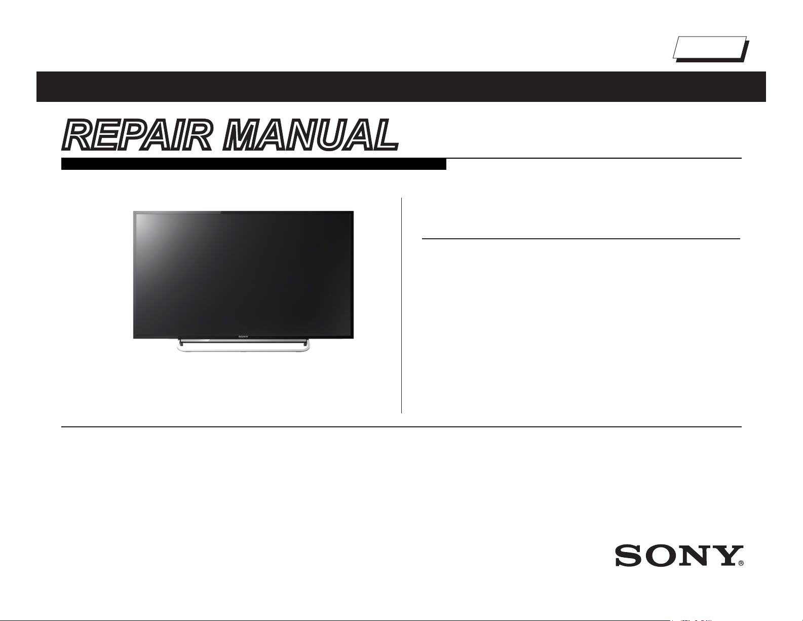
KDL-48W590B
LCD Digital Color TV
9-883-590-02
Page 2
TABLE OF CONTENTS
Cautions and Warnings ...................................................................................ii
Section 1 - Specications and Layouts ......................................................... 1
Specications ................................................................................................1
Checking the Accessories...................................................................................... 1
Board Layout .................................................................................................2
KDL-40W590B/48W600B ...................................................................................... 2
KDL-48W590B/48W600B ...................................................................................... 2
Wire Dressing ................................................................................................ 3
KDL-40W590B/40W600B ...................................................................................... 3
KDL-48W590B/48W600B ...................................................................................... 3
Section 2 - Troubleshooting ...........................................................................4
Diagnosing the Error .....................................................................................4
Viewing the Self Check Diagnosis History ............................................................. 4
Triage Chart ...................................................................................................5
Flowcharts and Diagrams .............................................................................. 6
Overall Block Diagram ........................................................................................... 6
Power and Control Block Diagram.........................................................................7
No Power Flowchart ..............................................................................................8
Standby LED Blinking Flowchart ...........................................................................9
Video Distortion Flowchart ...................................................................................10
Section 4 - Exploded View/Part Number Information ................................. 17
Table Top Stand ...........................................................................................17
KDL-40W590B/48W600B ............................................................................ 18
Connectors ..................................................................................................21
Screws ......................................................................................................... 22
Section 5 - Accessories/Part Number Information .....................................23
Accessories and Packaging ........................................................................23
Miscellaneous .............................................................................................. 23
Optional Accessories ................................................................................... 23
Remote Commander ...................................................................................23
Appendix A: Encryption Key Components ...............................................A-1
Section 3 - Repair Information ...................................................................... 11
Repairing the TV .......................................................................................... 11
Removing the Table Top Stand .................................................................... 11
Removing the Lower Cover ......................................................................... 11
Replacing the Main Board / Tuner Board ....................................................12
Removing the Speakers ..............................................................................16
Replacing the Switch Unit ...........................................................................16
KDL-40W590B/40W600B/48W590B/48W600B i
Page 3
CAUTIONS AND WARNINGS
CAUTION!!
These servicing instructions are for use by qualied service personnel only.
To reduce the risk of electric shock, do not perform any servicing other than
that contained in the operating instructions unless you are qualied to do so.
WARNING!!
An isolation transformer should be used during any service to avoid possible
shock hazard, in case of live chassis.
!
SAFETY-RELATED COMPONENT WARNING!!
There are critical components used in LCD color TVs that are important for
safety. These components are identied with shading and
schematic diagrams and the parts list. It is essential that these critical parts
be replaced only with the part number specied in the parts list to prevent
electric shock, re or other hazard.
NOTE: Do not modify the original design without obtaining written permission
from the manufacturer or you will void the original parts and labor warranty.
!
mark on the
ATTENTION!!
ATTENTION!!
Ces instructions de service sont à l’usage du personnel de service qualié
seulement. Pour prévenir le risque de choc électrique, ne pas faire l’entretien
autre que celui contenu dans le Mode d’emploi à moins que vous soyez
qualié faire ainsi.
ALERTE!!
An d’eviter tout risque d’electrocution provenant d’un chássis sous tension,
un transformateur d’isolement doit etre utilisé lors de tout dépannage.
!
ATTENTION AUX COMPOSANTS
RELATIFS A LA SECURITE!!
Les composants identies par une trame et par une marque
schemas de principe, les vues explosees et les listes de pieces sont d’une
importance critique pour la securite du fonctionnement. Ne les remplacer
que par des composants Sony dont le numero de piece est indique dans le
present manuel ou dans des supplements publies par Sony. Les reglages
de circuit dont l’importance est critique pour la securite du fonctionnement
sont identies dans le present manuel. Suivre ces procedures lors de
chaque remplacement de composants critiques, ou lorsqu’un mauvais
fonctionnement suspecte.
!
sur les
For safety reasons, component level repair of the Power Supply Boards
and/or the Inverter Boards is prohibited.
Pour des raisons de sécurité, Interdire de réparer ou remplacer les
composantes dans les blocs d’alimentation et/ou sur les modules d’inverseur.
ATTENTION!!
KDL-40W590B/40W600B/48W590B/48W600B ii
Page 4
CAUTIONS AND WARNINGS
To Exposed Metal
Parts on Set
0.15 µF
Earth Ground
AC
Voltmete
r
(0.75V)
Trouble Light
SAFETY CHECK-OUT
After correcting the original service problem, perform the following safety
checks before releasing the set to the customer:
1. Check the area of your repair for unsoldered or poorly soldered
connections. Check the entire board surface for solder splashes
and bridges.
2. Check the interboard wiring to ensure that no wires are “pinched” or
touching high-wattage resistors.
3. Check that all control knobs, shields, covers, ground straps and
mounting hardware have been replaced. Be absolutely certain that
you have replaced all the insulators.
4. Look for unauthorized replacement parts, particularly transistors,
that were installed during a previous repair. Point them out to the
customer and recommend their replacement.
5. Look for parts which, though functioning, show obvious signs of
deterioration. Point them out to the customer and recommend their
replacement.
6. Check the line cords for cracks and abrasion. Recommend the
replacement of any such line cord to the customer.
7. Check the antenna terminals, metal trim, “metallized” knobs, screws
and all other exposed metal parts for AC leakage. Check leakage
as described in “Leakage Test”.
The AC leakage from any exposed metal part to earth ground and from all
exposed metal parts to any exposed metal part having a return to chassis,
must not exceed 0.5 mA (500 microamperes). Leakage current can be
measured by any one of three methods.
LEAKAGE TEST
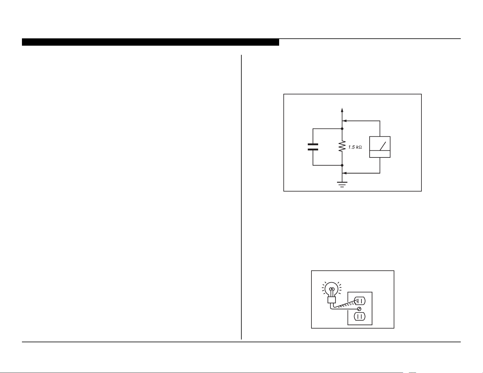
3. Measuring the voltage drop across a resistor by means of a VOM
or battery-operated AC voltmeter. The “limit” indication is 0.75 V, so
analog meters must have an accurate low voltage scale. Nearly all
battery-operated digital multimeters that have a 2 VAC range are
suitable. (see Figure A)
Figure A. Use an AC voltmeter to check AC leakage.
HOW TO FIND A GOOD EARTH GROUND
The cover-plate retaining screw on most AC outlet boxes is at earth ground.
Verify the AC outlet box retaining screw ground by connecting a 60W to
100W incandescent (not a neon or uorescent lamp) between the hot side of
the receptacle and the retaining screw. Try both slots, if necessary, to locate
the hot side on the line; the lamp should light at normal brilliance if the screw
is at ground potential. (see Figure B)
AC Outlet Box
KDL-40W590B/40W600B/48W590B/48W600B iii
1. A commercial leakage tester.
Follow the manufacturers’ instructions provided with the tester.
2. A battery-operated AC milliammeter.
Figure B. Checking for earth ground.
Page 5
SECTION 1 - SPECIFICATIONS AND LAYOUTS
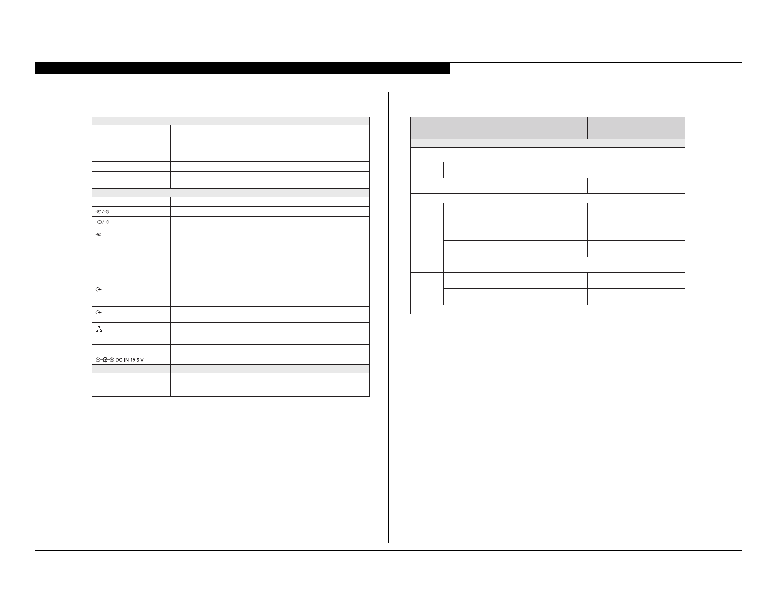
SPECIFICATIONS
System
Television system NTSC: American TV standard
Channel coverage
Panel system
Speaker output
Wireless technology
ATSC (8VSB terrestrial): ATSC compliant 8VSB
QAM on cable: ANSI/SCTE 07 2000 (Does not include CableCARD functionality)
Analog terrestrial: 2 - 69 / Digital terrestrial: 2 - 69
Analog Cable: 1 - 135 / Digital Cable: 1 - 135
LCD (Liquid Crystal Display) Panel, LED Backlight
8 W + 8 W
Protocol IEEE802.11a/b/g/n
Input/Output jacks
CABLE/ANTENNA
VIDEO IN 1
COMPONENT IN
VIDEO IN 2
HDMI IN 1/2/3/4
MHL
(Common with HDMI IN 1)
AUDIO OUT/ i Audio output (stereo mini jack)
DIGITAL AUDIO OUT
(OPTICAL)
LAN
USB/DLNA
75-ohm external terminal for RF inputs
Video / Audio input (phono jacks)
YP
BP R (Component Video): 1080p (60 Hz), 1080i (60 Hz), 720p (60 Hz), 480p, 480i
Audio input (phono jacks)
Video input (common phono pin with Y input)
Video: 1080p (30, 60 Hz), 1080/24p, 1080i (60 Hz), 720p (30, 60 Hz), 720/24p, 480p,
480i, PC Formats
Audio: 5.1 channel linear PCM: 32, 44.1 and 48 kHz, 16, 20 and 24 bits, Dolby Digital
ARC (Audio Return Channel) (HDMI IN 2 only)
Video: 1080p (30 Hz), 1080/24p, 1080i (60 Hz), 720p (30, 60 Hz), 720/24p, 480p, 480i
Audio: 5.1 channel linear PCM: 32, 44.1 and 48 kHz, 16, 20 and 24 bits, Dolby Digital
Headphone jac
(supports Subwoofer out)
Digital optical jack
(Two channel linear PCM, Dolby Digital)
10BASE-T/100BASE-TX connector (Connection speed may dier depending on the
network environment. 10BASE-T/100BASE-TX communication rate and
communication quality are not guaranteed for this TV)
Refer to the i-Manual for supported formats
AC adapter input (DC 19.5 V)
k
Others
Optional accessories
Camera and Microphone Unit: CMU-BR200/CMU-BR100
Wireless Subwoofer: SWF-BR100
MHL Cable: DLC-MB10/DLC-MB20/DLC-MC20
Model name KDL-48W600B/48W590B KDL-40W600B/40W590B
Power and others
Power requirement
*
in use
in standby
*
*
with stand
without stand
wall-mount hole
pattern
wall-mount screw
size
with stand
without stand
(mm)
(inches)
(mm)
(inches)
(mm)
(mm)
(kg)/(lb)
(kg)/(lb)
Power
consumption
Screen size
(inches measured diagonally)
Display resolution
Dimensions
Mass
Operating temperature
* Screen size, dimensions and mass are approximate values.
• Optional accessories availability depends on countries/region/TV model/stock.
• Design and specications are subject to change without notice.
• This TV set incorporates MHL 2.
Rating: Input 110-240 V AC, 50/60 Hz (U.S.A./Canada 120 V AC, 60 Hz)
Less than 0.4 W with 120 V AC and less than 0.5 W with 240 V AC
47.6 inches
(48 class)
1,086 × 675 × 181
7
/8 × 26 5/8 × 7 1/
42
1,086 × 646 × 90
7
/8 × 25 1/2 × 3 5/
42
03
19.5 V DC with AC adapter
75 W
1,920 dots (horizontal) × 1,080 lines (vertical)
4
8
M6 (8 -10 mm)
32 ºF – 104 ºF (0 ºC – 40 ºC)
CHECKING THE ACCESSORIES
- Remote Control*
- Size AAA batteries (2)
- AC Power Cord (1)
- AC Adapter (1)
- Fixing Screws for Table-Top
Stand (M5 × 20) (2)
- Wall-mount Adapter accessories
- Operating Instructions and
other documents
* Refer to the model name printed on
the remote control.
40 inches
926 × 584 × 162
1
/2 × 23 × 6 1/
36
926 × 556 × 89
1
/2 × 22 × 3 5/
36
2
8
003 × 003 002 × 0
5.71 / 9.77.22 / 3.01
3.61 / 4.7 9.12 / 9.9
KDL-40W590B/40W600B/48W590B/48W600B 1
Page 6
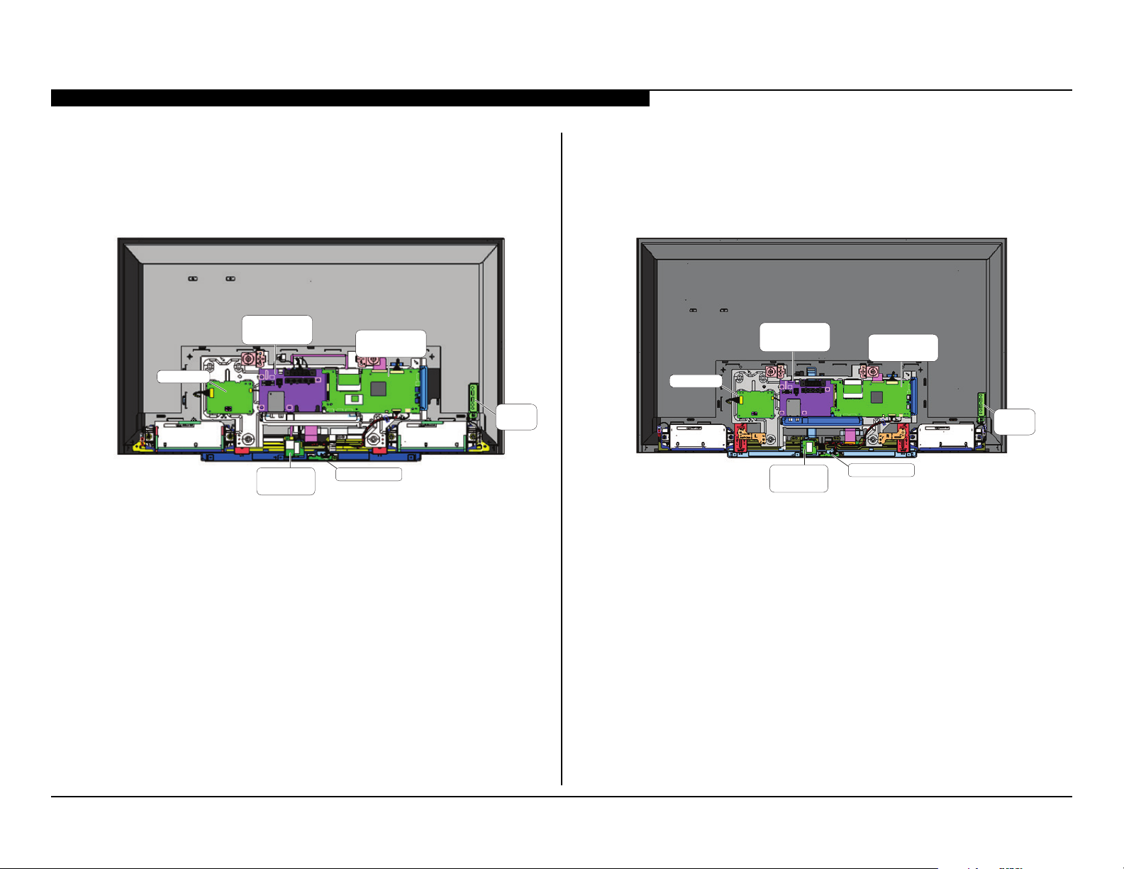
BOARD LAYOUT
SECTION 1 - SPECIFICATIONS AND LAYOUTS
KDL-40W590B/48W600B
LD BOARD
TUNER BOARD
(TUS BOARD)
LAN CARD
MAIN BOARD
(BAXL BOARD)
HJM BOARDWIRELESS
SWITCH
UNIT
KDL-48W590B/48W600B
TUNER BOARD
(TUS BOARD)
LD BOARD
WIRELESS
LAN CARD
MAIN BOARD
(BAXL BOARD)
HJM BOARD
SWITCH
UNIT
KDL-40W590B/40W600B/48W590B/48W600B 2
Page 7
SECTION 1 - SPECIFICATIONS AND LAYOUTS
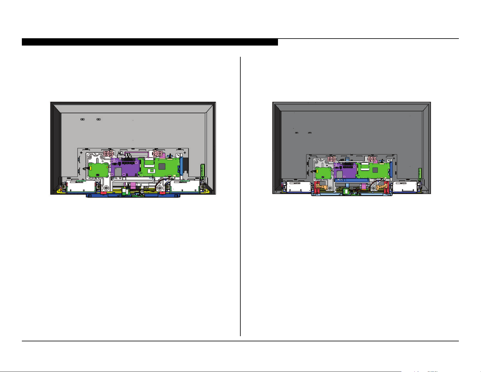
WIRE DRESSING
KDL-40W590B/40W600B KDL-48W590B/48W600B
KDL-40W590B/40W600B/48W590B/48W600B 3
Page 8
SECTION 2 - TROUBLESHOOTING
Self Diagnosis
*Format of Error History = YYMMDDhhmmss example 120123132522= Jan 23, 2012 13:25:22 (1:25:22PM)
Supported model
DIAGNOSING THE ERROR
Before servicing the Television:
1. Verify the TV has the symptom the customer indicated.
2. Check to see if the latest Software is installed.
a. If not, install the latest version.
3. Determine the replacement part required.
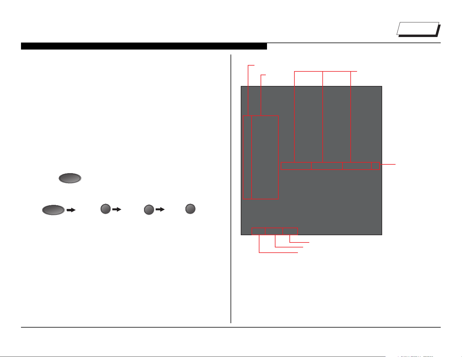
VIEWING THE SELF CHECK DIAGNOSIS HISTORY
When an error is detected, the Self Check screen records the number of
times the error occurred. This is helpful in conrming past occurrences of
an error and for determining if an error is intermittent when the customer is
not sure what is causing the television to shut down. If the screen displays
a “0”, no error has occurred.
DISPLAY
POWER
to turn on the TV and then turn it off again.
Channel
5
Volume - Power
I/0
1. Press
2. Press the following buttons on the Remote Commander within 1
second of each other:
StandBy LED
Blink Count
Diagnosis
Item
SELF CHECK
000 RESERVED --------------------- ------------------------------------------ 00
000 RESERVED --------------------- ------------------------------------------ 00
002MAIN_POWE --------------------- ------------------------------------------ 00
003 DC_ALERT --------------------- ------------------------------------------ 00
003 AUD_PROT --------------------- --------------------- ---------------------00
003 HDMI_EQ --------------------- --------------------- --------------------- 00
003 TU_DEMOD --------------------- ------------------------------------------ 00
004 VLED --------------------- ------------------------------------------00
004 LD_ERR --------------------- --------------------- ---------------------00
005 HFR_ERR --------------------- --------------------- ---------------------00
005 TCON_ERR120123132522 120123113645--------------------- 02
005 P_ID-ERR --------------------- --------------------- --------------------- 00
006 BACKLITE --------------------- ------------------------------------------00
007 TEMP_ERR --------------------- ------------------------------------------ 00
007 FAN_ERR --------------------- ------------------------------------------ 00
010 EMITTER --------------------- --------------------- ---------------------00
101 VPC_WDT --------------------- ------------------------------------------ 00
102 MEPS_WDT--------------------- ------------------------------------------ 00
103 HOST_WDT --------------------- ------------------------------------------00
104 STBY_WDT --------------------- ------------------------------------------ 00
Date and Time Display*
Error Count
(00-99)
NOTE: This differs from accessing Service Adjustments Mode (Volume +).
KDL-40W590B/40W600B/48W590B/48W600B 4
00345 000333 06789
Panel operation time by hour (MAX:65535)
Panel operation time by hour (MAX:65535)
Boot count (MAX:65535)
Boot count (MAX:65535)
Total operation time by hour (MAX:65535)
Total operation time by hour (MAX:65535)
NOTE: date and time must be set for this to work
SAMPLE SELF CHECK DIAGNOSIS PAGE
Page 9
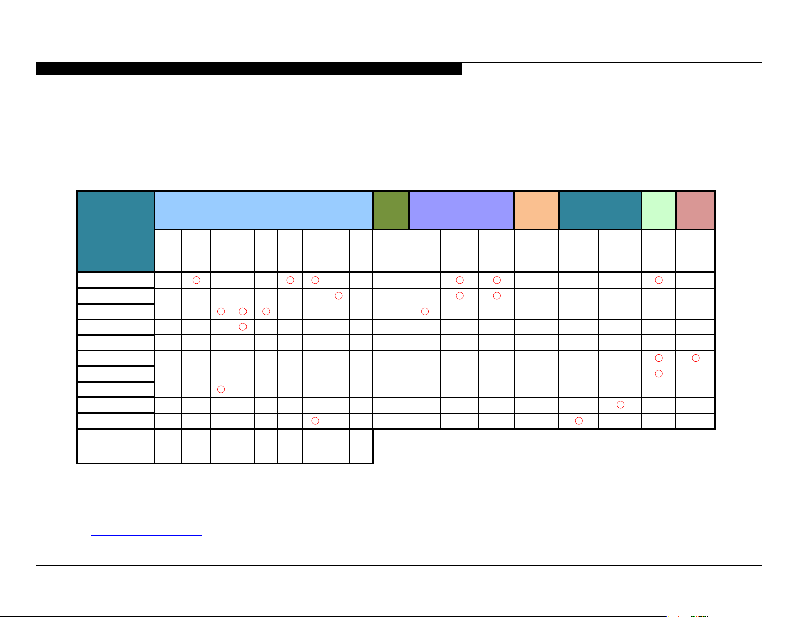
SECTION 2 - TROUBLESHOOTING
1. Confirm the symptom from the customer. Red Dot: (Primary) Most likely defective part.
3. Bring the primary component listed for that symptom.
▲
▲ ▲
▲ ▲
▲ ▲ ▲
▲
4. Follow the associated flowcharts in the Training Manual to isolate the board.
*NOTE: REFER TO LCD PANELS SERVICE MANUAL IN REFERENCE LIBRARY DATABASE
FOR CORRECT REPLACEMENT PARTS BASED ON SERIAL NUMBER.
TRIAGE CHART
Use this general Triage Chart to determine what may possibly be causing the error before going out to the customers location.
2. Select that symptom from the chart. Blue Triangle: (Secondary) Possible defective part.
5. Chart Color Code.
Board Reference
MAIN BOARD
TUNER BOARD
LCD PANEL
TCON
LVDS FFC
H BOARD
SPEAKER
LD BOARD
BT BOARD
WIFI
Problem
Symptoms - Shutdown. Power LED blinking
red diagnostics sequences
2X 3X 4X
▲ ▲
5X 6X 7X 8X 9X 10X
▲
▲
▲ ▲ ▲ ▲
▲ ▲ ▲ ▲
▲
POWER
AUDIO/
POWER
LD TCON
BACKLIGHT
TEMP
SOFT-
WARE
EMIT-
TER
No
Power
No White
Power
LED
Steady
lines or
dots
▲
Video
No Video
One of
Inputs
No Video
All Inputs
Remote
No Remote
Network
Wireless
can't
connect
Bluetooth
can't
connect
Audio
No
Audio
▲
▲
▲
Smart
Core
No LED
To access the most recent version of the Triage documents for the models listed in this manual, login into the Sony Authorized Service Portal
at http://www.sony.com/asp.
KDL-40W590B/40W600B/48W590B/48W600B 5
Page 10
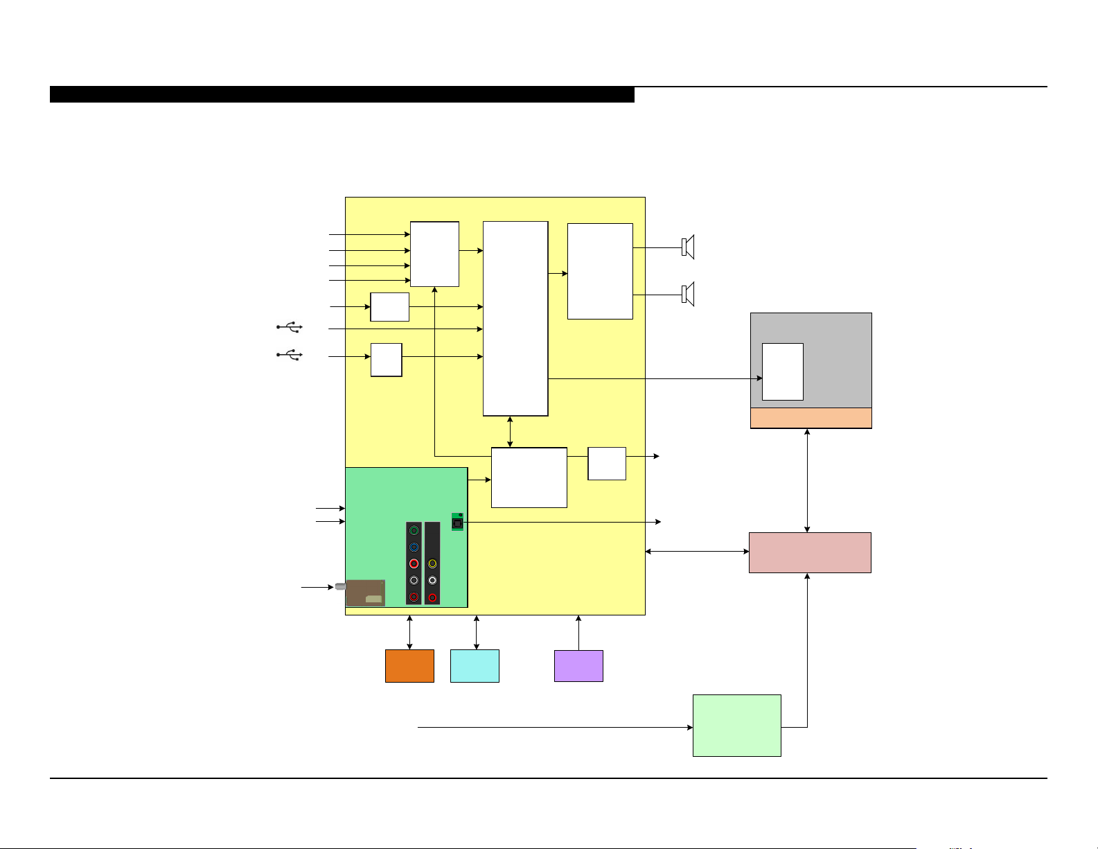
FLOWCHARTS AND DIAGRAMS
OVERALL BLOCK DIAGRAM
SECTION 2 - TROUBLESHOOTING
MAIN BOARD
HDMI 1 / MHL
HDMI 2 /ARC
HDMI 3
HDMI 4
ETHERNET
VIDEO 1 CVBS
VIDEO 2 CVBS/COMP
RF
USB
USB
TUNER
SWITCH
ETHER
PHY
USB
HUB
TUNER BOARD
HDMI
EQ
A/V
DECODER
VIDEO
PROCESS
TUNER
SWITCH
DEMODULATOR
UNIT
ADC / DACAMP
AUDIO
AMP
AUDIO
AMP
BAXL
L
R
LVDS
HEADPHONES
OUT
OPTICAL
AUDIO OUT
LCD PANEL
HFR
TCON
LED BACKLIGHTS
LOCAL DIMMING
LD
WIFI
AC IN
IR RX
LED’s
HJM
SWITCH
UNIT
AC ADAPTOR
KDL-40W590B/40W600B/48W590B/48W600B 6
Page 11
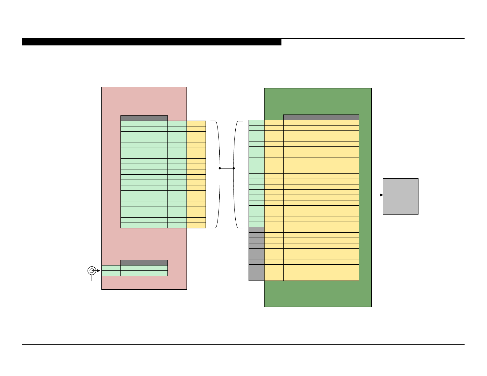
POWER AND CONTROL BLOCK DIAGRAM
SECTION 2 - TROUBLESHOOTING
DC IN
LOCAL DIMMING
CN2001
PWM0 20 2
PWM1 19 3
IP_REF 18 8
PWM2 17 4
AC_MON 16 12
MAIN_PWR 15 11
GND 14 25
STBY_+3.3V 13 14
GND 12 24
REG+12V 11 17
GND 10 23
19.5V_HOLD 9 18
GND 8 22
19.5V_SS 7 19
GND 6 16
GND 5 15
+19.5V 4 21
+19.5V 3 20
LD_ERR 2 28
LD_STBY 1 9
AC_IN
1 DC-IN
2 DC_GND
LD
MAIN BOARD
CN9101
2 28 BL_ERR
14 25 GND
12 24 GND
10 23 GND
8 22 GND
4 21 +19.5V(12V)
3 20 +19.5V(12V)
7 19 +19.5V_SS(12V)
9 18 +19.5V_HOLD(12V)
11 17 REG+12V
6 16 GND
5 15 GND
13 14 STBY+3.3V
16 12 AC_OFF_DET
15 11 POWER_ON
1 9 LD_STBY
18 8 IP_REF
17 4 LD_PWM_2 / SPI0_2(DATAF)
19 3 LD_PWM_1 / SPI0_1(LATF)
20 2 LD_PWM_0 /SPI0_0(EMIT IN)
NC 30 GND
NC 29 GND
NC 27 BL_ON
NC 26 DIGITAL_STBY
NC 13 TCON_ON
NC 10 SA_MODE
NC 7 FB_REF
NC 6 LD_PWR_4 / SPI0_RDATA / BLU_TEMP
NC 5 LD_PWM_3 / SPI0_3(CLKF)
NC 1 LD_MODE_SW
PANEL
MODULE
BAXL
KDL-40W590B/40W600B/48W590B/48W600B 7
Page 12
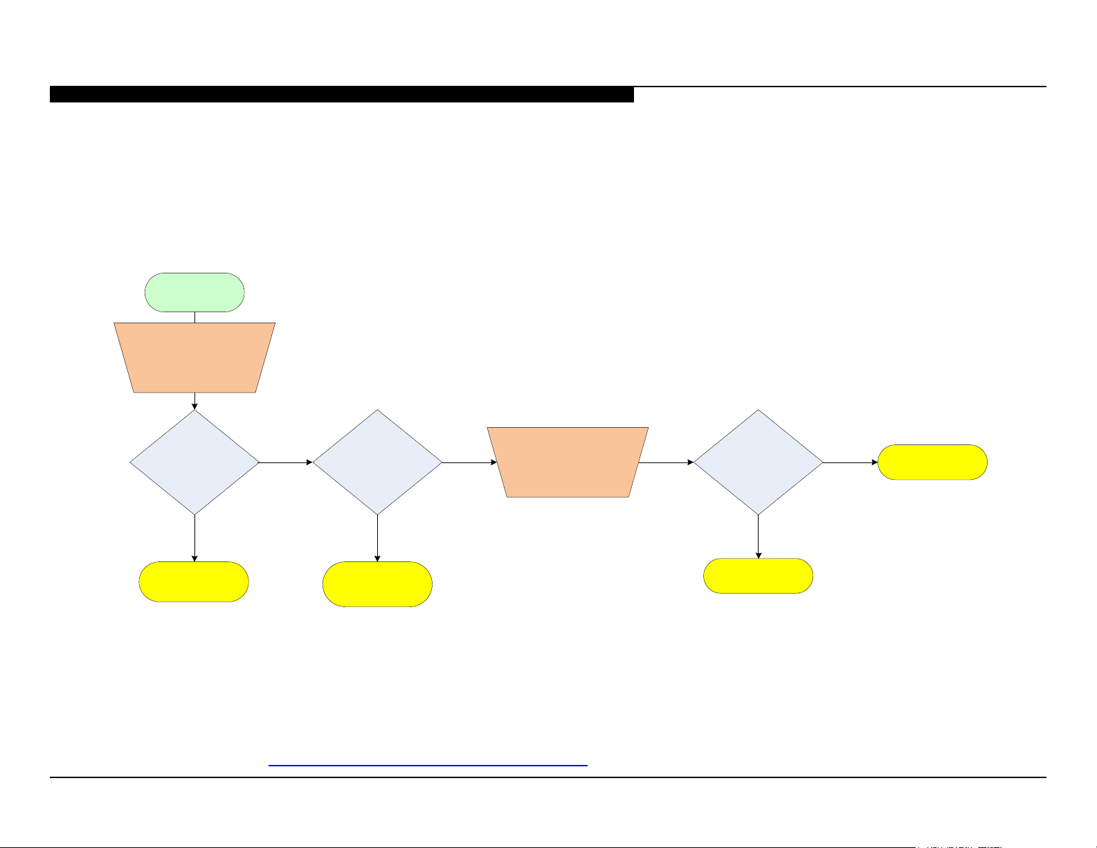
NO POWER FLOWCHART
No Power
Substitute 19.5V AC
Adaptor with another.
SECTION 2 - TROUBLESHOOTING
Does TV turn ON?
Yes
AC Adaptor*
*For Part Number information, refer to “Section 4 - Exploded View/Part Number Information” on page 17.
No
Is red light blinking
on front of TV?
Yes
See Standby LED
Blinking chart
No
Check STBY 3.3V
Pin 13 CN2001
LD Board.
Is Pin 13 CN2001
on 3.3 volts?
LD Board*
Yes
Main Board*
KDL-40W590B/40W600B/48W590B/48W600B 8
Page 13
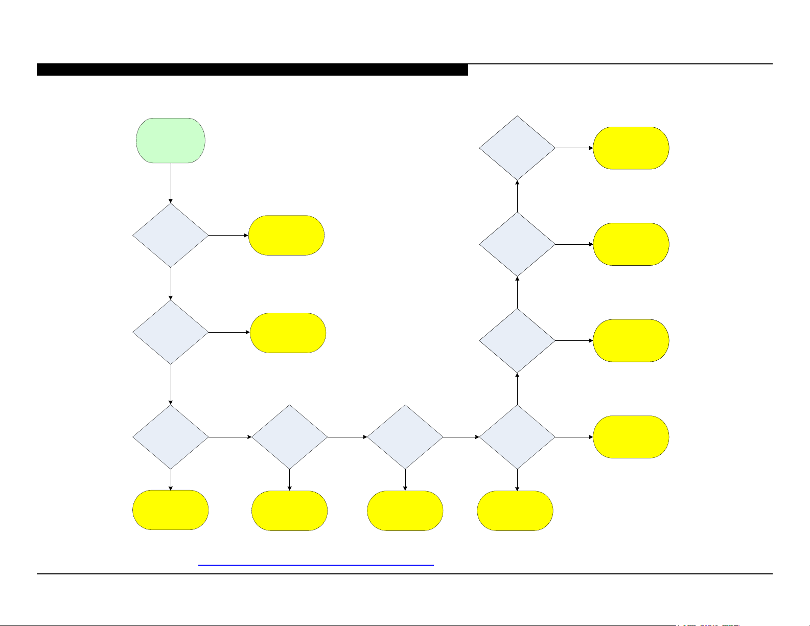
STANDBY LED BLINKING FLOWCHART
Protect
Shutdown.
Standby LED
Blinking
SECTION 2 - TROUBLESHOOTING
10X HEM3 Board10X
No
Yes
TCON
Placa Principal*
(LCD Panel)*
2X
No
3X
No
4X
Yes
LCD Panel /
LD Board *
Yes
Yes
No
Main Board*
Main Board*
5X
Yes
TCON
(LCD Panel)*
10X HEM3 Board9X
No
10X HEM3 Board8X
No
No
6X
Yes
LCD Panel *
No
7X
Immediately
Main Board*
Yes
Yes
After a while
Tuner Board*
Placa Principal*
Main Board
Wireless LAN Card*
Check ventilation
/
*For Part Number information, refer to “Section 4 - Exploded View/Part Number Information” on page 17.
KDL-40W590B/40W600B/48W590B/48W600B 9
Page 14
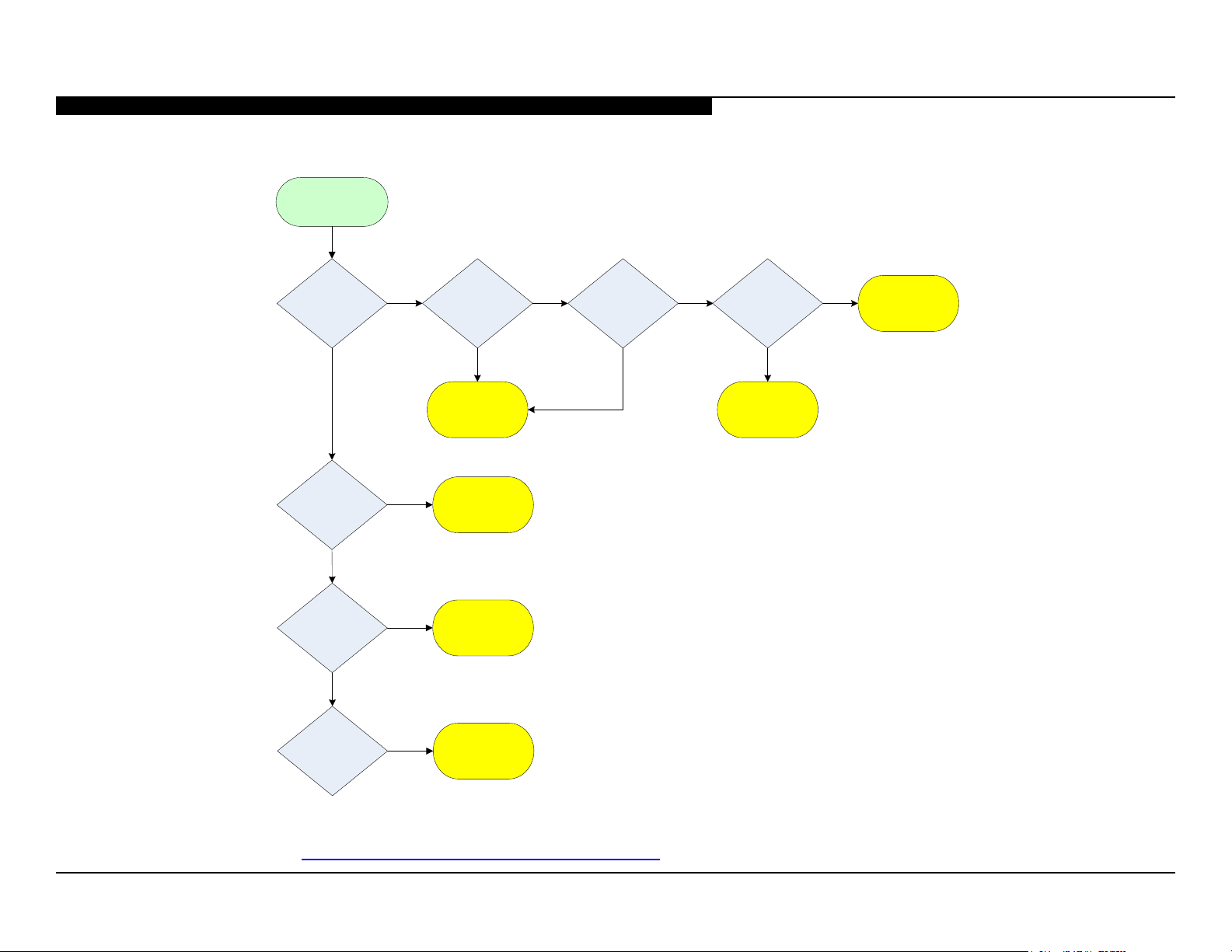
VIDEO DISTORTION FLOWCHART
Video Distortion
SECTION 2 - TROUBLESHOOTING
Is distortion
across entire
screen?
No
Any horizontal
lines?
No
Any single or
isolated vertical
lines?
No
Yes
Yes
Yes
Improper or
missing
colors?
Yes
Main Board*
LCD Panel*
LCD Panel*
No
Vertical lines
or bars?
No
Yes
Lines
move when
wide-mode
changed?
No
TCON*
(LCD Panel)
Yes
Main Board*
More than 1
vertical band?
*For Part Number information, refer to “Section 4 - Exploded View/Part Number Information” on page 17.
Yes
TCON*
(LCD Panel)
KDL-40W590B/40W600B/48W590B/48W600B 10
Page 15
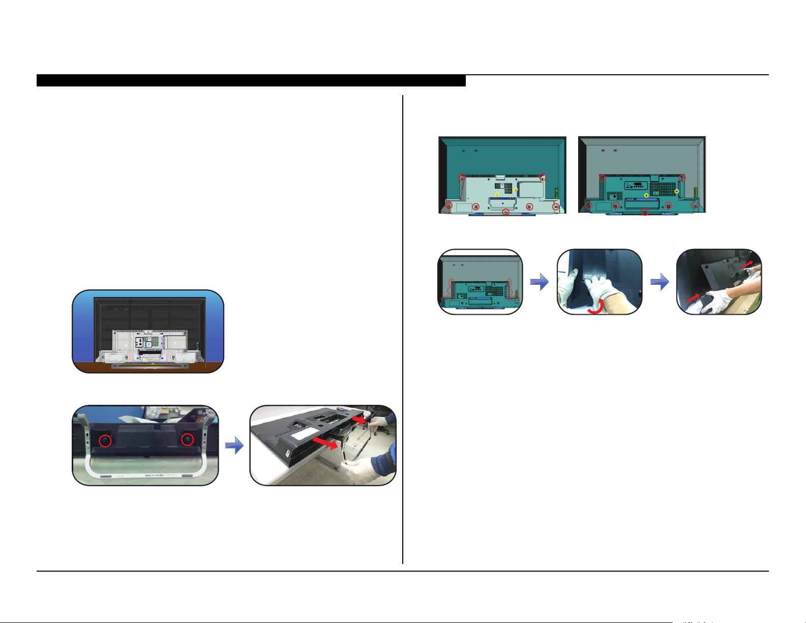
SECTION 3 - REPAIR INFORMATION
REPAIRING THE TV
If the latest Software does not correct the issue, complete the following:
1. Verify the television has the symptom the customer indicated.
2. Replace part causing the symptom.
3. Install the latest version of Software (Required for ALL repairs).
4. Perform the required service adjustments and checks.
5. Verify the repair resolved the issue.
REMOVING THE TABLE TOP STAND
1. Place TV face down on a soft and at surface.
2. Remove 2 screws from Stand Shaft and carefully detach as shown.
REMOVING THE LOWER COVER
1. Locate and remove all screws from Lower Cover.
KDL-40W590B/KDL-40W600B KDL-48W590B/KDL-48W600B
2. Firmly detach from areas shown to remove Lower Cover from the TV.
KDL-40W590B/40W600B/48W590B/48W600B 11
Page 16
SECTION 3 - REPAIR INFORMATION
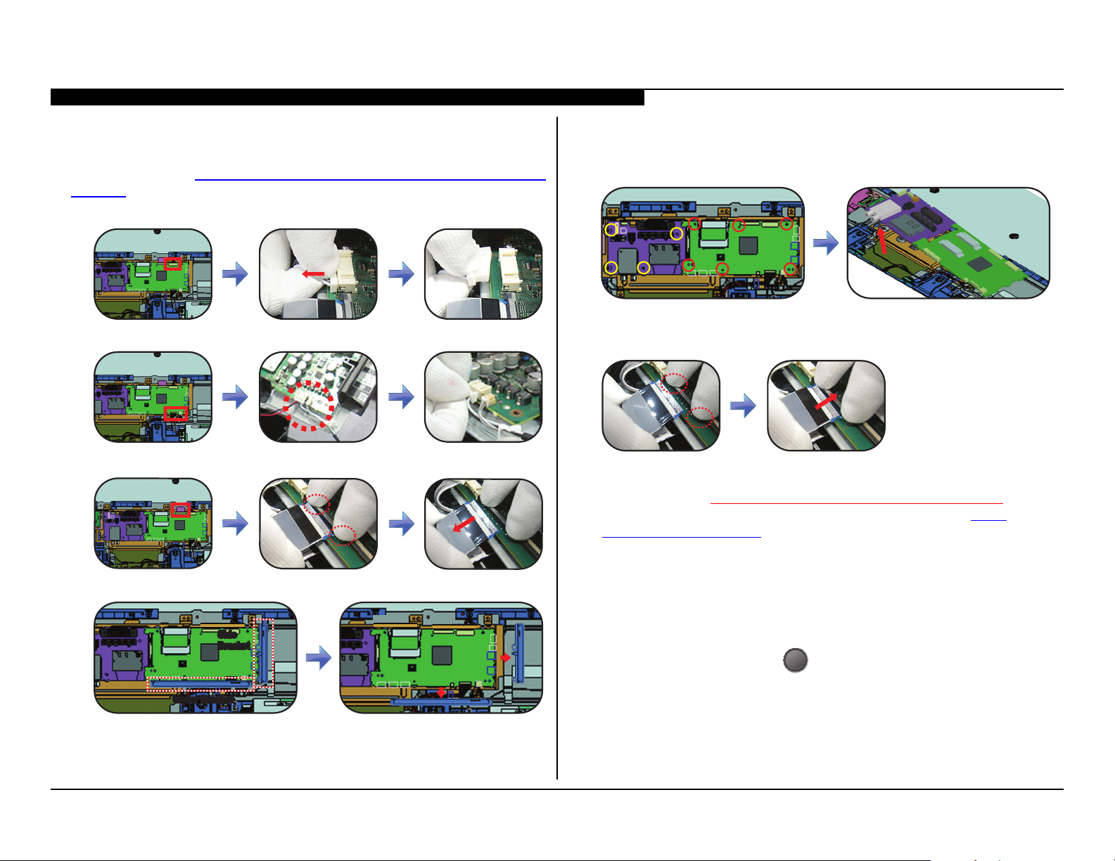
REPLACING THE MAIN BOARD / TUNER BOARD
The Main Board used in these models is available for repair. For Part Number
information refer to Section 4 - Exploded View/Part Number Information on
page 17.
1. Disconnect Harness from the Main Board.
2. Locate and disconnect all remaining connectors.
3. Press down the 2 locking clips and pull LVDS cable to release.
4. Slide brackets to detach from Main Board.
5. Locate and remove screws from the Tuner Board and Main Board,
then lift to detach.
6. Install the new Main Board and/or Tuner Board and screws.
7. Reconnect the LVDS Cable and all other connectors.
8. Update the Software.
After ALL repairs UPDATE the SOFTWARE to the latest version.
Instructions are included with the Software package on the Sony
Authorized Service Portal website.
a. Insert the USB device with the latest Software into one of the TVs’
USB ports.
b. Connect TV to AC power.
Side
Side
Bracket
Bracket
Under Bracket
Under Bracket
c. Wait at least 20 seconds.
d. Press the Power button
on the TV to turn it ON.
I/0
e. Wait until the Software update is completed.
KDL-40W590B/40W600B/48W590B/48W600B 12
Page 17
SECTION 3 - REPAIR INFORMATION
KDL-48W600B
ATSC_UC_BASE
US/CND
MODEL NO
KDL-48W590B
SERIAL NO
5000001
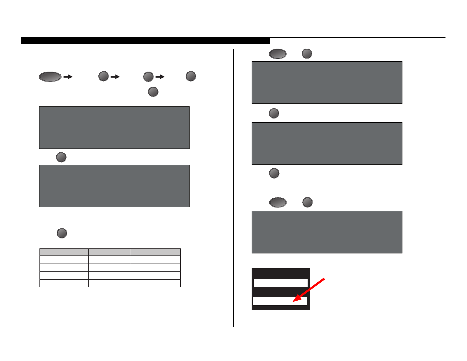
9. To access Service Mode, turn TV ON and OFF again then press
the following buttons within 1 second of each other:
DISPLAY
Channel 5 Volume + Power
I/0
10. When the DIGITAL Menu appears, press 2 until 002 MODEL
category displays.
DIGITAL SERVICE
002 MODEL
000 BOARD CHECK
11. Press 1 until 002 DEST item displays.
DIGITAL SERVICE
002 MODEL
002 DEST
ATSC_UC_BASE
CAUTION: If the incorrect Destination Data Value is selected,
it may corrupt the Sofware requiring a Main Board replacement.
12. Press 3 until the correct destination of the TV displays.
(Use the table below for reference).
Model Name Destination Data Value
KDL-40W590B
KDL-48W600B
KDL-40W590B
US/CND
US/CND
US/CND
ATSC_UC_BASE
ATSC_UC_BASE
ATSC_UC_BASE
13. Press
MUTE
then 0 to save the changes.
DIGITAL SERVICE
002 MODEL
002 DEST
ATSC_UC_BASE
WRITE
14. Press 1 until 003 MODELNAME displays.
DIGITAL SERVICE
002 MODEL
003 MODELNAME
_________
15. Press 3 until the model displayed matches the model of the TV.
CAUTION: The Model Name can only be selected once. Be sure
to verify the information is correct before saving the changes.
16. Press
then 0 to save the changes.
MUTE
DIGITAL SERVICE
002 MODEL
003 MODELNAMEKDL-48W590B
WRITE
17. Locate the Serial Number for the TV on the side of the Rear Cover.
KDL-40W590B/40W600B/48W590B/48W600B 13
Page 18
SECTION 3 - REPAIR INFORMATION
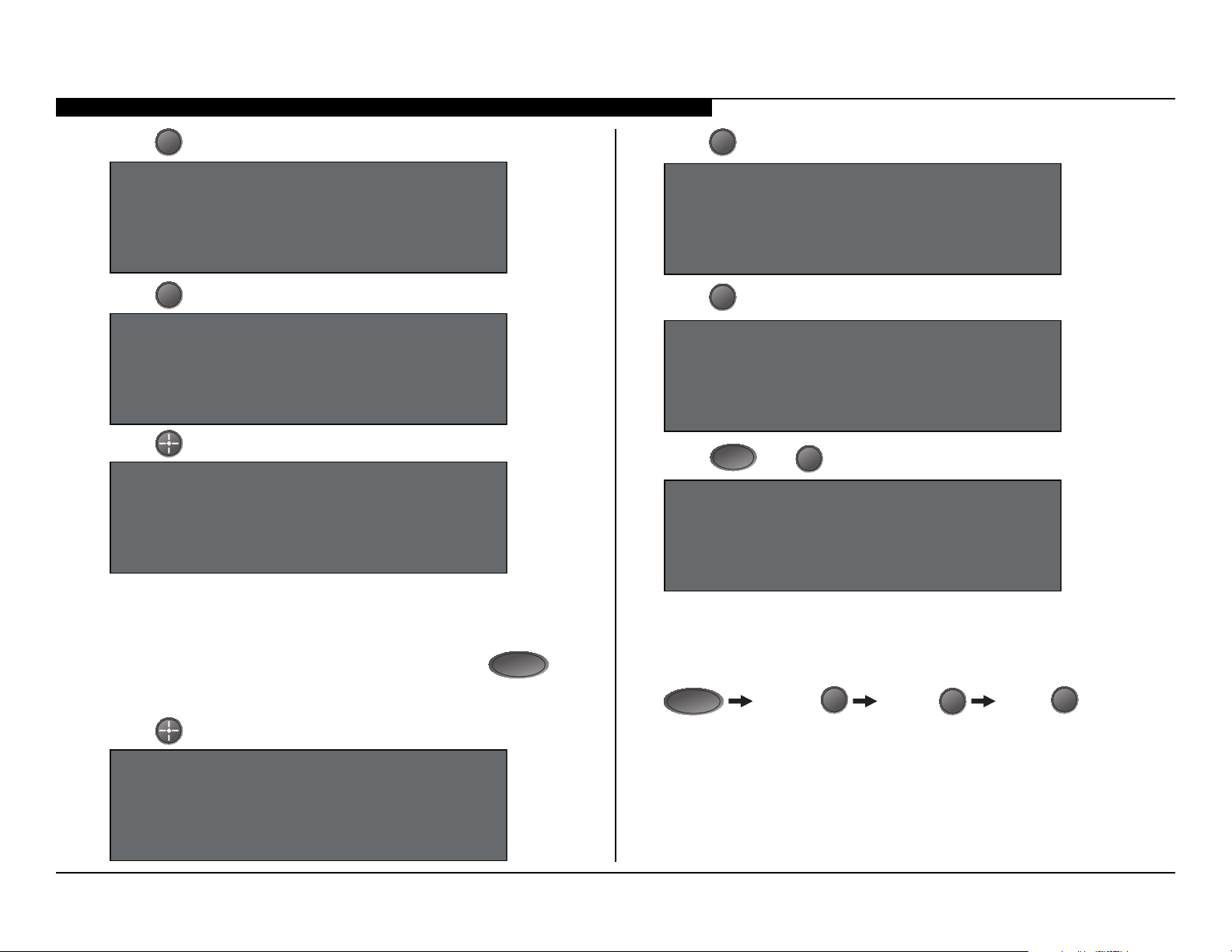
18. Press 1 until 004 SERIAL item displays.
DIGITAL SERVICE
002 MODEL
004 SERIAL
19. Press 0 to display the Serial Number Edit option.
DIGITAL (MODEL) SERVICE
SerialNumberEdit
*1 SerialNumber
20. Press to display the Serial Number input screen.
DIGITAL (MODEL) SERVICE
SerialNumberEdit
*1 SerialNumber
Please Input serial number
(0000000-99999999)
_ _ _ _ _ _ _
CAUTION: The Serial Number can only be selected once. Be sure
to verify the information is correct before saving the changes.
21. Enter the Serial Number of the TV.
NOTE: If the incorrect Serial Number is entered, press
to go back to the Serial Number input screen and re-enter
the correct number.
RETURN
23. Press 1 until 006 VAR_TYPE item displays.
DIGITAL SERVICE
002 MODEL
006 VAR_TYPE
24. Press 3 until UC option displays.
DIGITAL SERVICE
002 MODEL
006 VAR_TYPE UC
25. Press
26. Cycle AC Power (Unplug and plug AC Cord from the outlet).
27. Access Service Mode, by pressing the following buttons within
1 second of each other:
MUTE
then 0 to save the changes.
DIGITAL SERVICE
002 MODEL
006 VAR_TYPE UC
WRITE
DISPLAY
Channel 5 Volume + Power
I/0
22. Press to save the Serial Number.
DIGITAL (MODEL) SERVICE
SerialNumberEdit
*1 SerialNumber
5000001 WRITE
KDL-40W590B/40W600B/48W590B/48W600B 14
Page 19
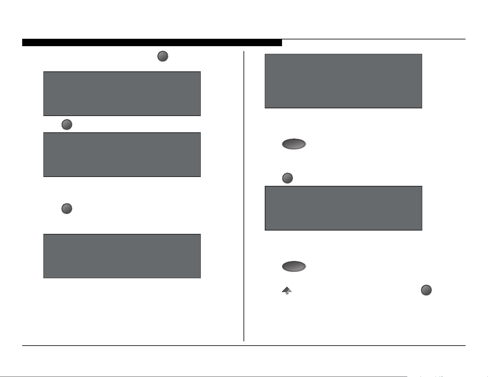
28. When the DIGITAL Menu appears, press 2 until 002 MODEL
category displays.
DIGITAL SERVICE
002 MODEL
000 BOARD CHECK
29. Press 0 to select the 000 BOARD CHECK item.
SECTION 3 - REPAIR INFORMATION
DIGITAL (MODEL) SERVICE
Board Check
OK
TUNER BOARD OPTION: PCA / HTL
TUNER BOARD OPTION is changed correctly
CAUTION: If the Main Board is a mismatch to the Tuner Board,
a “NG: WRONG COMBINATION OF MAIN BOARD AND TUNER
BOARD” message will display.
DIGITAL (MODEL) SERVICE
Board Check
1. Replace MAIN BOARD (and TUNER BOARD)
2. Replace TUNER BOARD only
When replacing the Main Board and/or Tuner Board:
30. Press 1 to verify the Main Board replacement results.
NOTE: Either one of the following messages indicates
a correct process.
DIGITAL (MODEL) SERVICE
Board Check
OK
TUNER BOARD OPTION: STANDARD
31. Press
RETURN
on the Remote Commander.
When replacing the Tuner Board only:
32. Press 2 to verify the Tuner Board replacement results.
DIGITAL (MODEL) SERVICE
Board Check
OK
TUNER BOARD OPTION: STANDARD
CAUTION: If the Tuner Board is a mismatch to the Main Board,
a “NG: DIFFERENT KIND OF TUNER BOARD HAS BEEN
CONNECTED” message will display.
33. Press
RETURN
on the Remote Commander.
34. Turn the TV OFF.
35. Press on the Remote Commander and Power button
I/0
to set unit to Shipping Condition.
on TV
KDL-40W590B/40W600B/48W590B/48W600B 15
Page 20
SECTION 3 - REPAIR INFORMATION
SELF CHECK
000 RESERVED --------------------- ------------------------------------------ 00
000 RESERVED --------------------- ------------------------------------------ 00
002 MAIN_POWE --------------------- ------------------------------------------ 00
003 DC_ALERT --------------------- ------------------------------------------ 00
003 AUD_PROT --------------------- ------------------------------------------00
003 HDMI_EQ --------------------- --------------------- --------------------- 00
003 TU_DEMOD --------------------- --------------------- --------------------- 00
004 VLED --------------------- ------------------------------------------00
004 LD_ERR --------------------- ------------------------------------------00
005 HFR_ERR --------------------- ------------------------------------------ 00
005 TCON_ERR 120123132522 120123113645--------------------- 02
005 P_ID-ERR --------------------- --------------------- --------------------- 00
006 BACKLITE --------------------- ----------------------------------------- 00
007 TEMP_ERR --------------------- --------------------- --------------------- 00
007 FAN_ERR --------------------- ------------------------------------------00
010 EMITTER --------------------- --------------------- --------------------- 00
101 VPC_WDT --------------------- --------------------- --------------------- 00
102 MEPS_WDT --------------------- ------------------------------------------ 00
103 HOST_WDT --------------------- ------------------------------------------ 00
104 STBY_WDT --------------------- ------------------------------------------00
00345 000333 06789
Error Count
36. Clear the Self Check screen.
a. Press
POWER
to exit Service Mode.
b. Press the following buttons on the Remote Commander within
1 second of each other:
DISPLAY
Channel 5 Volume - Power
I/0
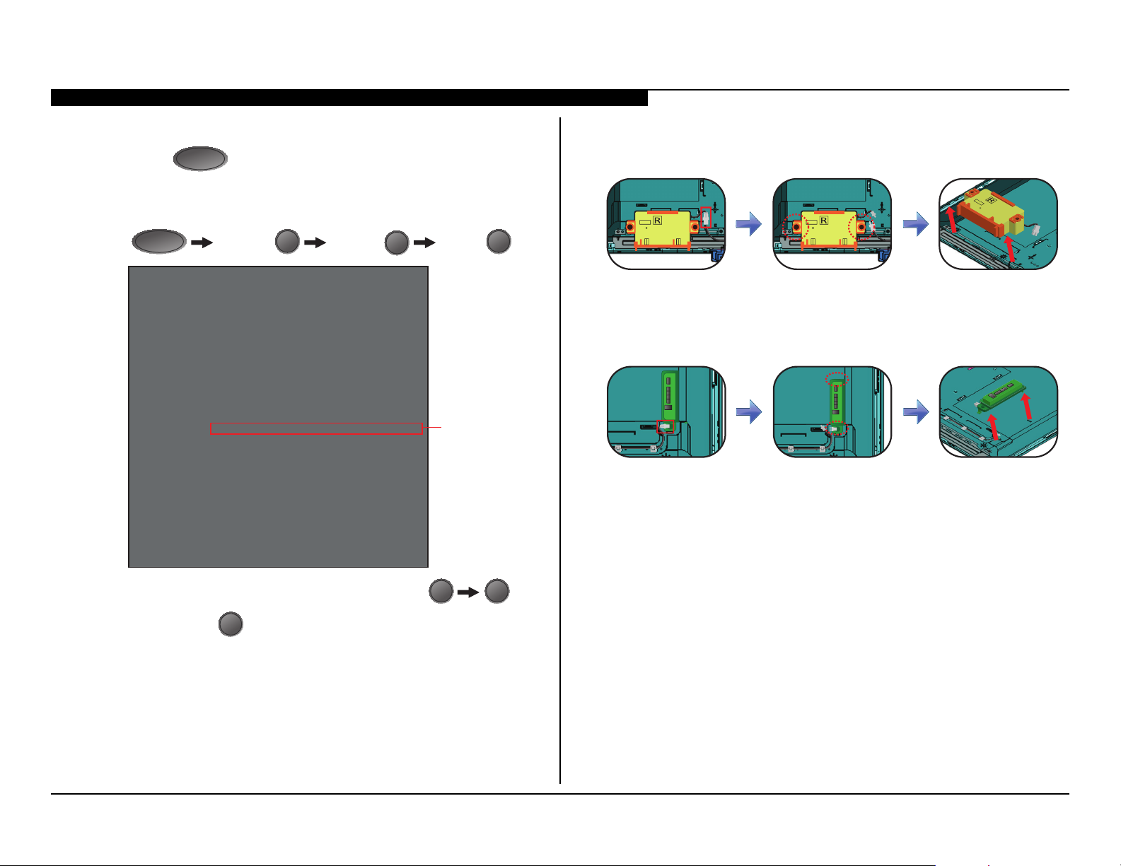
REMOVING THE SPEAKERS
1. Disconnect connectors from each Speaker, then lift to detach.
REPLACING THE SWITCH UNIT
1. Disconnect connector from Switch Unit, then lift to detach.
2. Install the new Switch Unit and connector.
KDL-40W590B/40W600B/48W590B/48W600B 16
c. To clear the error history and error count press 8
d. Press Power
to exit Self Check Mode.
I/0
37. Cycle AC Power (Unplug and plug AC Cord from the outlet).
0
.
Page 21
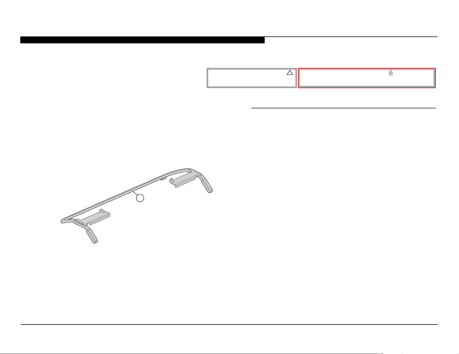
SECTION 4 - EXPLODED VIEW/PART NUMBER INFORMATION
TABLE TOP STAND
Components not identied by a part number or description
are not stocked because they are seldom required for routine
service.
NOTE: The components identied by shading and !
mark are critical for safety.
Replace only with part number specied.
REF. NO. PART NO. DESCRIPTION
The component parts of an assembly are indicated by the reference numbers in
the far right column of the parts list and within the dotted lines of the diagram.
NOTE: The components identied by a red outline and a mark contain condential
information. Specic instructions must be adhered to whenever these components are
repaired and/or replaced. (See Appendix A)
1 4-484-942-01 STAND SHAFT (M)
(KDL-40W590B/40W600B ONLY)
1 4-484-943-01 STAND SHAFT (ML)
(KDL-48W590B/48W600B ONLY)
1
KDL-40W590B/40W600B/48W590B/48W600B 17
Page 22
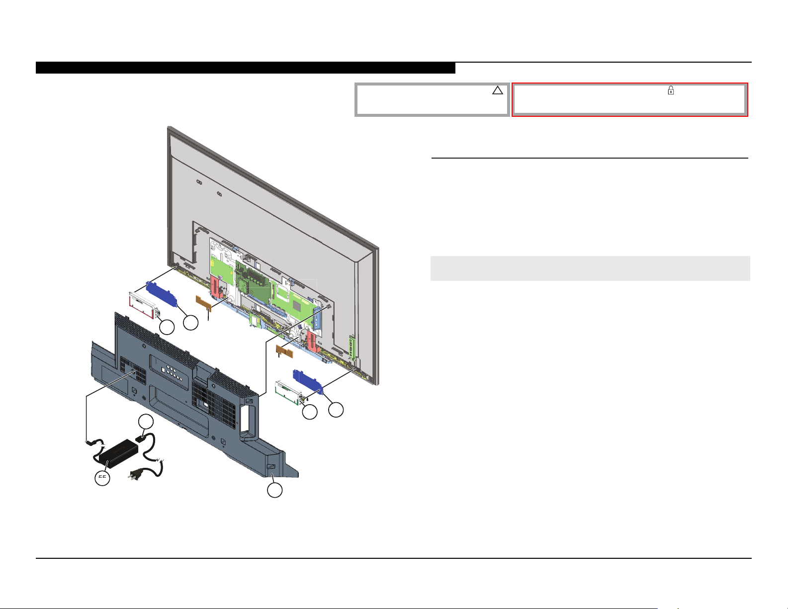
SECTION 4 - EXPLODED VIEW/PART NUMBER INFORMATION
4
KDL-40W590B/48W600B
51
56
*Metal
Bridge
Right
*Metal
Bridge
Left
NOTE: The components identied by shading and !
mark are critical for safety.
Replace only with part number specied.
REF. NO. PART NO. DESCRIPTION
51 4-476-162-01 BRACKET, SP
52 1-858-963-11 SPEAKER BOX (LEFT)
53 4-532-487-01 LOWER COVER (UNDER COVER 40)
(KDL-40W590B/40W600B ONLY)
53 4-532-488-01 LOWER COVER (UNDER COVER 48)
(KDL-48W590B/48W600B ONLY)
!
54 1-838-955-41 POWER SUPPLY CORD
!
55 1-492-734-11 AC ADAPTOR (85W)
56 1-858-963-21 SPEAKER BOX (RIGHT)
NOTE: The components identied by a red outline and a mark contain condential
information. Specic instructions must be adhered to whenever these components are
repaired and/or replaced. (See Appendix A)
51
54555
53
* Reinstall Metal Bridge Right and Metal Bridge Left
when replacing the LCD Panel.
(KDL-48W590B/48W600B ONLY)
52
KDL-40W590B/40W600B/48W590B/48W600B 18
Page 23
SECTION 4 - EXPLODED VIEW/PART NUMBER INFORMATION
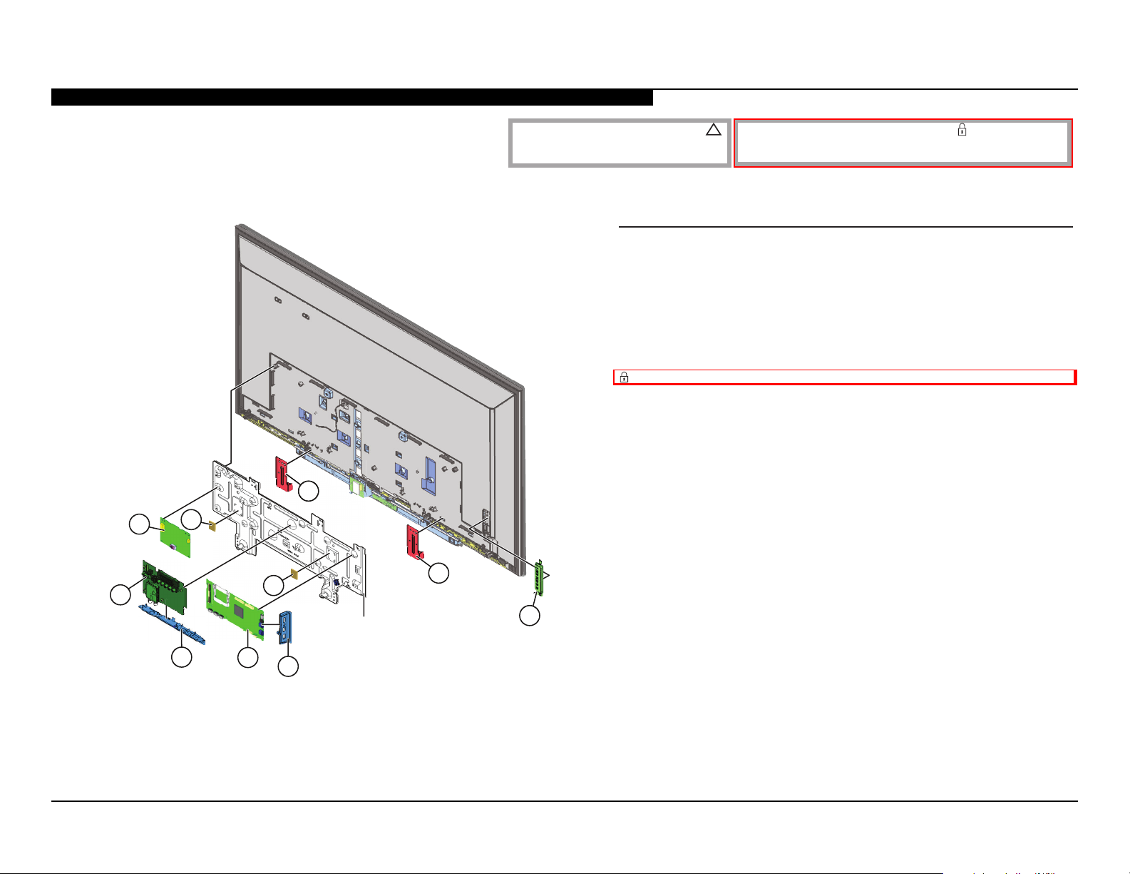
KDL-40W590B/48W600B
108
103
102
NOTE: The components identied by shading and !
mark are critical for safety.
Replace only with part number specied.
REF. NO. PART NO. DESCRIPTION
101 1-474-560-11 SWITCH UNIT
102 4-476-164-01 STAND BRACKET
103 4-440-057-01 SHEET, THERMAL (AYU2)
ORDER THIS PART WHEN REPLACING THE MAIN BOARD
AND/OR LD BOARD.
104 4-528-972-01 BRACKET, SIDE
105 A-2037-764-A BAXL BOARD, COMPLETE
AFTER REPLACING THE MAIN BOARD, YOU MUST UPDATE
THE SOFTWARE TO THE LATEST VERSION.
106 4-528-973-01 BRACKET, UNDER
107 A-1998-231-A TUS BOARD, COMPLETE
AFTER REPLACING THE TUNER BOARD, YOU MUST UPDATE
THE SOFTWARE TO THE LATEST VERSION.
NOTE: The components identied by a red outline and a mark contain condential
information. Specic instructions must be adhered to whenever these components are
repaired and/or replaced. (See Appendix A)
108 A-1983-521-A LD BOARD, MOUNTED
(KDL-40W590B/40W600B ONLY)
108 A-1983-522-A LD BOARD, MOUNTED
(KDL-48W590B/48W600B ONLY)
107
106
* Reinstall Main Board Plate
when replacing the LCD Panel.
105
103
104
Main Board Plate*
102
101
KDL-40W590B/40W600B/48W590B/48W600B 19
Page 24
SECTION 4 - EXPLODED VIEW/PART NUMBER INFORMATION
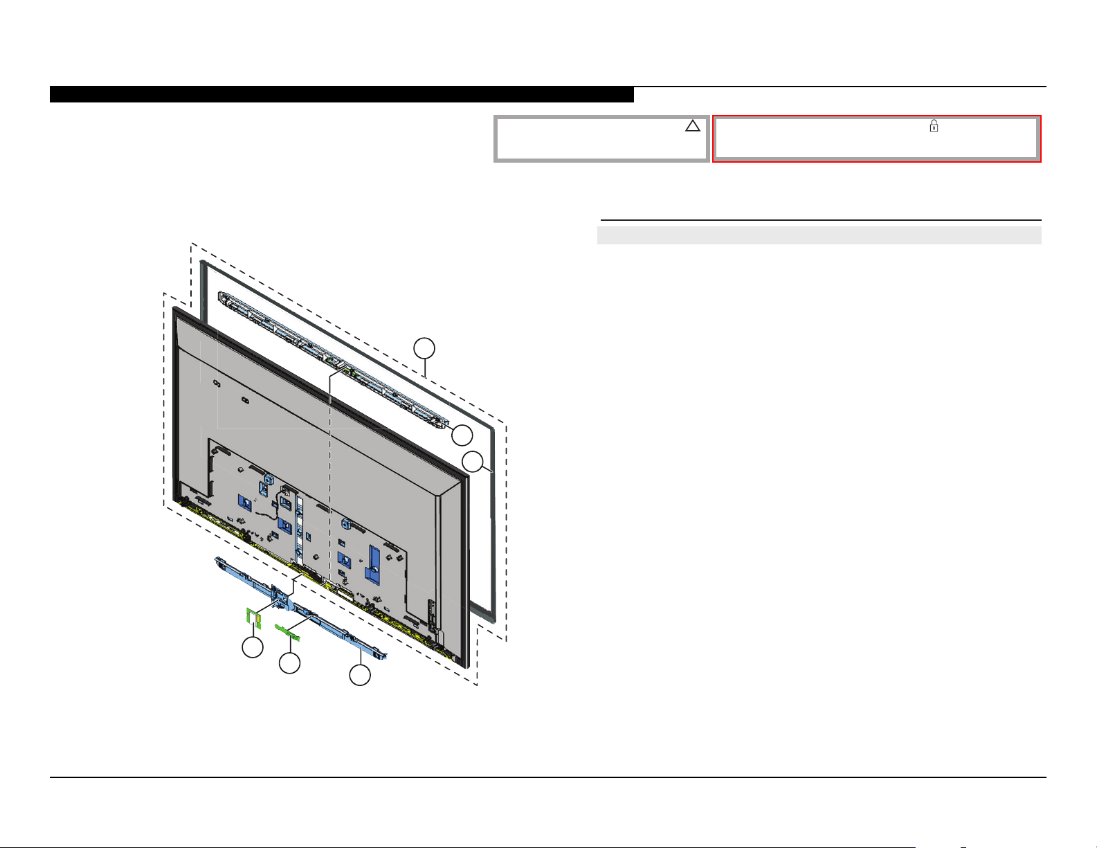
KDL-40W580B/48W580B
151
152
NOTE: The components identied by shading and !
mark are critical for safety.
Replace only with part number specied.
REF. NO. PART NO. DESCRIPTION [ASSEMBLY INCLUDES]
!
151 NA PANEL MODULE [152, 153]
FOR LCD PANEL AND TCON BOARD PART NUMBER
INFORMATION REFER TO THE LCD PANELS SERVICE MANUAL.
152 4-476-157-11 PANEL, ORNAMENTAL L
(KDL-40W590B ONLY)
152 4-476-157-61 PANEL, ORNAMENTAL L
(KDL-40W600B ONLY)
152 4-476-156-11 PANEL, ORNAMENTAL LL
(KDL-48W590B ONLY)
152 4-476-156-61 PANEL, ORNAMENTAL LL
(KDL-48W600B ONLY)
153
153 4-527-493-01 BEZEL (40)
(KDL-40W590B/40W600B ONLY)
153 4-527-494-01 BEZEL (48)
(KDL-48W590B/48W600B ONLY)
NOTE: The components identied by a red outline and a mark contain condential
information. Specic instructions must be adhered to whenever these components are
repaired and/or replaced. (See Appendix A)
154 4-476-160-01 COVER, OP L
(KDL-40W590B/40W600B ONLY)
154 4-476-159-01 COVER, OP LL
(KDL-48W590B/48W600B ONLY)
155 A-1979-006-A HJM BOARD, MOUNTED
156
155
154
156 1-458-723-11 WIRELESS LAN CARD
KDL-40W590B/40W600B/48W590B/48W600B 20
Page 25
SECTION 4 - EXPLODED VIEW/PART NUMBER INFORMATION
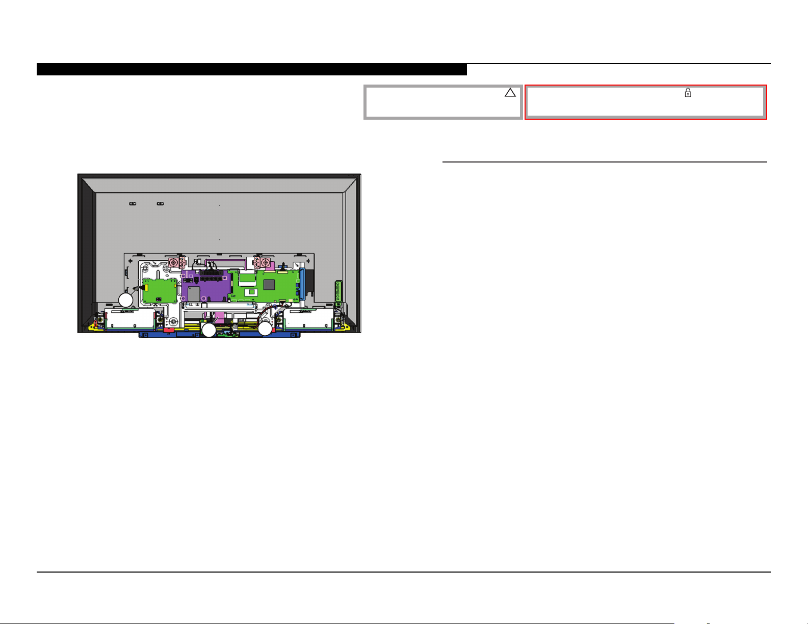
CONNECTORS
201
202
203
NOTE: The components identied by shading and !
mark are critical for safety.
Replace only with part number specied.
REF. NO. PART NO. DESCRIPTION
201 1-910-804-48 CONNECTOR ASSEMBLY 20P
202 1-848-217-11 (LVDS) FLEXIBLE FLAT CABLE 51P
(KDL-40W590B/40W600B ONLY)
202 1-848-218-11 (LVDS) FLEXIBLE FLAT CABLE 51P
(KDL-48W590B/48W600B ONLY)
203 1-910-804-49 HARNESS ASSEMBLY
(KDL-40W590B/40W600B ONLY)
203 1-910-804-52 HARNESS ASSEMBLY
(KDL-48W590B/48W600B ONLY)
NOTE: The components identied by a red outline and a mark contain condential
information. Specic instructions must be adhered to whenever these components are
repaired and/or replaced. (See Appendix A)
KDL-40W590B/40W600B/48W590B/48W600B 21
Page 26
SECTION 4 - EXPLODED VIEW/PART NUMBER INFORMATION
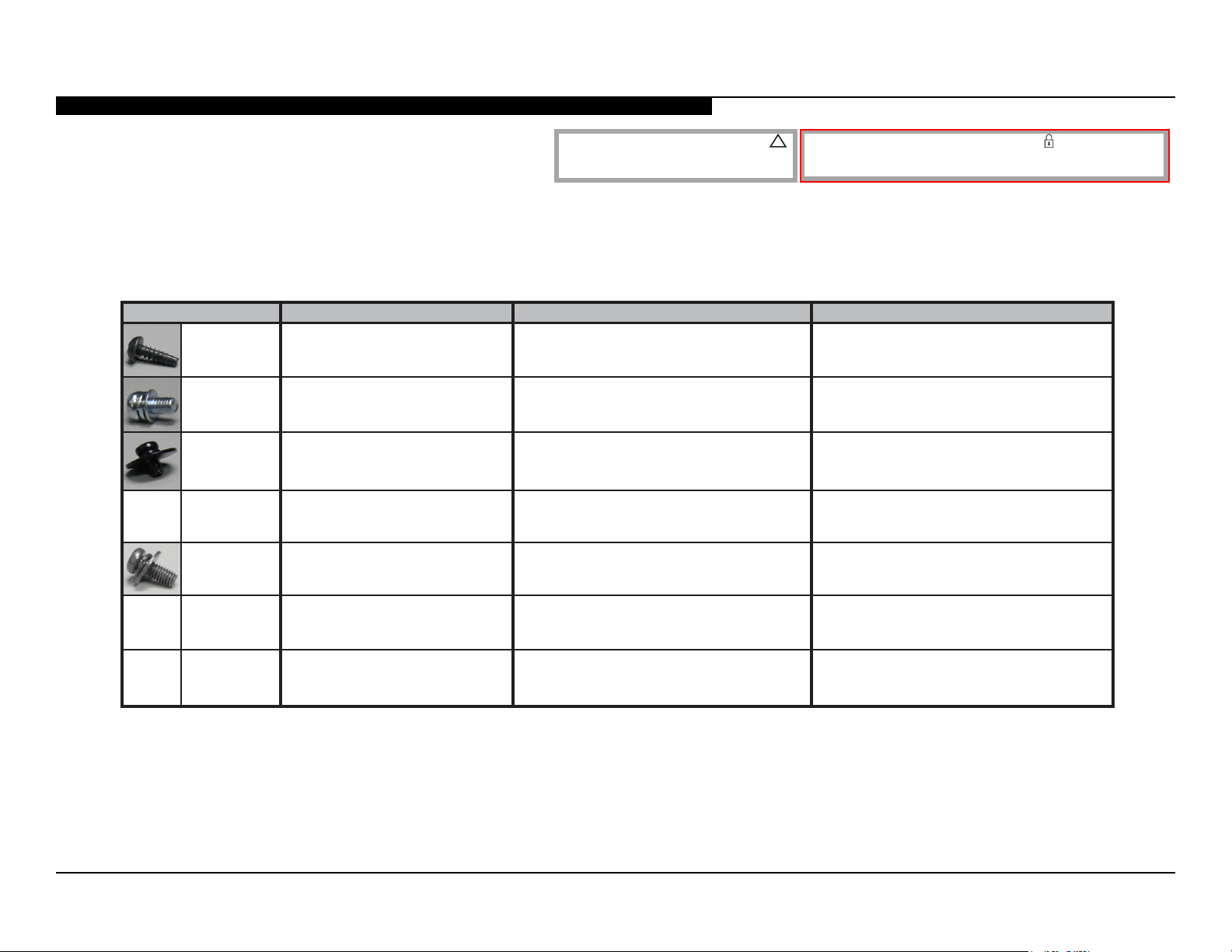
SCREWS
NA
P/N DESCRIPTION
2-580-639-01
2-990-421-41
4-256-393-01
7-685-647-79
4-159-298-21
SCREW, +BVTP 4X12 TYPE2 IT-3
SCREW (+PSW) (M3X6)
SCREW, +PSW M3X6 W12
SCREW, +BVTP 3X10 TYPE IT-3
SCREW, +PSW M4X10
NOTE: The components identied by shading and !
mark are critical for safety.
Replace only with part number specied.
KDL-40W590B/40W600B
Bracket Under to Lower Cover (1)
Bracket Side to Lower Cover (1)
Main Board (6), LD Board (4)
Tuner Board (4)
Lower Cover (6), Main Board Plate (5),
OP Cover a Bezel (3), Stand Brackets (2)
Brackets Vesa (2) , Stand Brackets (2)
NOTE: The components identied by a red outline and a mark contain condential
information. Specic instructions must be adhered to whenever these components are
repaired and/or replaced. (See Appendix A)
KDL-48W590B/48W600B
Bracket Under to Lower Cover (1)
Bracket Side to Lower Cover (1)
Main Board (6), LD Board (4)
Tuner Board (4)
Metal Bridge Right (2), Metal Bridge Left (2)
Wireless Lan Card (2), Lower Cover (7),
OP Cover a Bezel (2), Stand Brackets (2),
Main Board Plate (5)
Brackets Vesa (2) , Stand Brackets (2)
NA
NA
SCREW, +PSW M5X203-452-815-21 Stand to TV (2)
SCREW, +PSW M6X162-580-611-01 Wall Mount Adapter (3)
Stand to TV (2)
Arm Left to Stand Shaft (2),
Arm Right to Stand Shaft (2)
KDL-40W590B/40W600B/48W590B/48W600B 22
Page 27
SECTION 5 - ACCESSORIES/PART NUMBER INFORMATION
ACCESSORIES AND PACKAGING
PART NO. DESCRIPTION
3-452-815-21 SCREW, +PSW M5X20
(SCREWS TO ATTACH TABLE TOP STAND TO LCD TV)
For product protection and safety reasons, Sony strongly recommends
that you use the screws provided with the TV.
CAUTION: These screws cannot be used to secure the TV
to the Wall Mount Brackets.
4-535-392-01 SCREW, +PSW M6X16
(SCREWS TO ATTACH TV TO WALL MOUNT)
4-531-135-01 WALL HUNG BRACKET ASSEMBLY L
4-484-526-01 BRACKET, VESA
4-428-537-01 CLAMPER, AC ADAPTER
3-299-071-08 FLYER, SAFETY
4-489-955-11 MANUAL, INSTRUCTION (ENGLISH VERSION)
4-489-956-31 MANUAL, INSTRUCTION (SPANISH VERSION)
(KDL-40W600B/48W600B ONLY)
OPTIONAL ACCESSORIES
PART NO. DESCRIPTION
4-414-470-01 SUPPORT BELT KIT
REMOTE COMMANDER
PART NO. DESCRIPTION
1-492-767-11 REMOTE COMMANDER (RM-YD103)
MISCELLANEOUS
PART NO. DESCRIPTION
4-100-136-01 SHEET (CORE), C
4-256-454-02 SPACER (G A)
7-600-031-97 TAPE (3M 1350FB-1) 15MMX66M BLK
7-600-031-96 TAPE (3M 1350FW-1) 15MMX66M WHT
3-876-036-71 UNI-LABEL, BLANK
KDL-40W590B/40W600B/48W590B/48W600B 23
Page 28
APPENDIX A: ENCRYPTION KEY COMPONENTS
Encryption key components developed by Sony Corporation contain condential information and shall be handled under the non-disclosure obligations provided
in the applicable agreement with Sony Corporation (and/or its subsidiary).
As part of this agreement specic instructions must be adhered to whenever a Circuit Board containing encryption key components is repaired and/or replaced
pursuant to the following:
1. In the service manual the Circuit Board(s) containing encryption key components shall be identied with a red outline and a .
2. Only repair boards or components listed in the service manual shall be utilized for replacement and/or repair.
3. Disassembly, decryption or reverse-engineering component(s) is strictly prohibited.
4. Any board in which the Servicer replaces an encryption key component must be placed back into the set it orignally came from and the replaced
defective component MUST BE DESTROYED. Boards cannot be swapped.
5. If a Circuit Board identied with a red outline and a in the service manual is deemed to be defective:
a. and if a core charge is imposed and is covered under the product warranty, the defective un-repaired or modied board MUST BE RETURNED to
Sony.
b. and if the core charge is NOT covered under the product warranty, the defective un-repaired or modied board MUST BE DESTROYED.
6. If a unit is destroyed (such as eld scrap), the Circuit Board identied with a red outline and a in the service manual MUST BE DESTROYED.
is a trademark of Sony Electronics.
Reproduction in whole or part without written permission is prohibited. All rights reserved.
Sony Corporation
9-883-590-02
Sony SSOA
TV Service Engineering
Service Publications Department
2014BJ74WEB-1
English
© 2014.2
KDL-40W590B/40W600B/48W590B/48W600B A-1
 Loading...