

Sony KDL-46SL140, KDL-40SL140 Owner’s Manual

KDL-40SL140
KDL-46SL140
R IA
© 2008 Sony Corporation
Operating Instructions

Owner's Record
The model and serial numbers are located at
the real" of the TV. Record these numbers in
the spaces provided below. Relier to them
whenever you call upon your Sony dealer
regarding this TV.
Model Name
Serial No,
CAUTION
To prevent electric shock, do not use this
polarized AC plug with an extension cord,
receptacle or other outlet unless the blades can
be fully inserted to prevent blade exposure.
Declaration of Conformity
Trade Name: SONY
Model: K[)L-4I)SL 14()/KDL-46SL 140
Responsible Party: Sony Electronics Inc.
Address: 16530 Via Esprilln
San Diego, CA 92127 U.S.A.
Telephone Number: 858-942-2230
This device complies with part 15 of the FCC
rules. Operation is suhject to the f_tllnwing two
conditkms: (1) This device may not cause
harmfi_fl interference, and (2) this device must
accept any interference received, including
intcr[i:_v.nce that may cause undesired operation.
NOTIFICATION
This equipment has been tested and lbund to
comply with tire limits fk)r a Class B digital
device, pursuant to Part 15 of the FCC Rules.
These limits are designed to provide reasonable
protection against harmfifl interli_rence in a
residential installation. This equipment generates,
uses and can radiate radio frequency energy and,
if not installed and used in accordance with the
instructions, may cause harmf\fl interlbreuce to
radio communications. However, there is no
guarantee that interfi_rence will not occur in a
pallicular installatkm. If this equipment does
cause harmf\fl interfi_reuce to radio or television
reception, which can be determined by turning the
equipment off and on, the user is encouraged to
try to correct the iuterlbrence by one or more of
the lbllowing measures:
[] Reorient or relocate the receiving antenna.
[] Increase the separation between the
equipment and receiver.
[] Connect the equipment into an outlet on a
circuit difllzrent fl'om that to which the
receiver is connected.
[] Consult tire dealer or an experienced
radio/TV technician lot help.
Pursuant to FCC regulations, you are
cautioned that any changes or modifications
not expressly approved in this manual could
void your authority to operate this
equipment.
Safety
[] Operate the TV onl> on 120 V AC.
[] Use the AC power cord specified h 3 Sony
and suitable fk_rthe voltage where you use it.
[] The plug is designed, for sallzty pm'pnses,
to fit into the wall outlet only one way. If
you are unable to insert the plug fully into
the outlet, contact your dealer.
[] If any liquid or solid object should fall
inside the cabinet, unplug the TV
immediately and have it checked by
qualified service personnel before
operating it further.
[] If you will not be using the TV for several
days, disconnect the power by pulling the
plug itself. Never pull on the cord.
[] When disconnecting AC power cord, tire
power cord should be easily accessible for
disconnection.
[] For details concerning safety precautions,
see "Safety and Regulatory Booklet".
Installing
[] The TV should be installed nero" an easil_
accessible power outlet.
[] To prevent internal heat buildup, dn not
blnck the ventilation openings.
[] Do not install tire TV in a hot or humid
place, or in a place subject to excessive
dust or mechanical vibration.
[] Avoid operating the TV at temperatures
below 41 °F (5°C).
[] If the TV is transported directly from a
cold to a warm location, or if the room
temperature changes suddenly, the picture
may be blurred or show poor color due to
moisture condensation. In this case,
please wait a llzw horn's to let the moisture
evaporate be[k>re turning on the TV.
[] To obtain tire best picture, do not expose
the screen tn direct illumination or direct
sunlight. It is recommended to use spot
lighting directed down from the ceiling or
to cover the windows that lace the screen
with opaque drapery. It is desirable to
install the TV in a room where the flnor
and walls are nnt of a reflective material.
CAUTION
Use the fk_llnwing Snn_ TVs only with the
following WALL-MOUNT BRACKET or
TV-stan(l.
KDL-40SL140 KDL-465L140
SU-WL500
SU-FL3OOM SU-FL3OOL
SU-FL71M
Use with other WALL-MOUNT BRACKET or
TV-stand may cause instability and possibly
result in injury.
To Customers
Sufficient expertise is required lor installing the
specified TV. Be sure tn subcontract the
installation to Sony dealer or licensed
contractors and pay adequate attention tn sallzty
during tire installation.
Note
This television includes a QAM demodulator
which should allow you to receive unscramhled
digital cable television programming via
subscription service to a cable service provider.
Availability of digital cable television
programming in your area depends on tire type
of programming and signal provided by your
cable service prnvider.
For Customers in Canada
This Class B digital apparatus complies with
Canadian 1CES4103.
For Customers in the United
States
Lamp in this product contains
mercury. Disposal of these
materials may be regulated due to
environmental considerations. For
disposal or recycling information,
please contact yourlocal authorities
or the Electronic Industries
Alliance (www.eiae.org).
Licensing Information
Macintosh is a trademark licensed to Apple,
1uc., registered in the U.S.A. and other countries.
Manufactured under license from Dolby
Laboratories. "Dolby" and the dnuble-D symbol
are trademarks of Dnlby Laboratories.
This TV incorporates High-Definition
Multimedia Interface (HDMI _M) technology.
HDMI, the HDMI logo and High-Definition
Multimedia luterlace are trademarks or
registered trademarks of HDMI Licensing, LLC.
TruSurrnund XT, SRS and (Q) symbol are
trademarks of SRS Labs, lnc. TruSurround XT
technology is incorporated under license from
SRS Labs, Inc.
Fergasnn Patent Properties, LLC:
U.S. Patent No. 5,717,422
U.S. Patent No. 6, 816, 141
Blu-ray is a trademark.
"BRAVIA" and B RAV[A, BRAVIA Theatre
Syuc and [] are trademarks or registered marks
of Sony Corporation.
"PLAYSTATION" is a registered trademark
and "PS3" is a trademark of Sony Computer
Entertainment Inc.
H;:3m|
DIGITAL
rrv"
2

The Four Steps to Stunning HD Experience:
Set, Sound, Source, and Setup ................ 4
Picture Quality and Aspect Ratio .................. 4
Using BRAVIA Theatre Sync TM with
Control for HDMI ...................................... 19
1. Installing the TV ......................................... 5
How to Carry the TV .................................... 5
How to Attach the Table-Top Stand ............ 5
Securing the TV ........................................... 6
Bundling the Connecting Cables ................. 8
Preparation for Wall-Mounting ..................... 8
Installing the Wall-Mount Bracket ................ 9
When Installing the TV Against a Wall or
Enclosed Area .................................... 11
2. Locating Inputs and Outputs .................. 12
3. Connecting the TV ................................... 14
Cable System and/or VHF/UHF ................ 14
HD Cable Box/HD Satellite Box ................. 14
PC .............................................................. 16
Other Equipment ....................................... 17
4. Setting Up the Channel List -
Initial Setup ............................................. 18
Inserting Batteries ........................................ 20
When Using the Remote Control ................. 20
Remote Control ............................................. 21
TV Controls/Indicators ................................. 25
Navigating through TV Menus ..................... 27
Menu Descriptions ........................................ 27
=aM"Using the Shortcuts Menu .................... 28
[] Using the Picture Menu ........................ 30
j_ Using the Sound Menu ......................... 31
[_]Using the Screen Menu ........................ 32
C_Using the Channel Menu ...................... 34
E-'6Using the Parental Lock ....................... 35
[] Using the Setup Menu .......................... 38
Troubleshooting ............................................ 41
Specifications ................................................ 44
Index ............................................................... 45
Quick Setup Guide (separate volume)
Provides a variety of optional equipment
connection diagrams,
Customer Support
United States http://www,sony,com/tvsupport
Canada http://www,sony,ca/su pport
On-line Registration
United States http://productregistration.sony.com
Canada http://www.sonystyle.ca/registration
3

Thank you for purchasing this Sony BRAVIA_>high-definition television. The quality of the image you see on
your BRAVlA TV is only as good as the quality of the signal it receives. To experience the stunning detail of
your new BRAVlA TV, you need access to HD programming. Your BRAVlA TV can receive and display HD
programming from:
• Over-the-air broadcasting via HD-quality antenna
• HD cable subscription
• HD satellite subscription
• Blu-ray Disc TM player or other external equipment
Contact your cable or satellite provider for information on upgrading to HD programming.
To learn more about HDTV, visit:
U.S.A http://www.sony.com/HDTV
Canada http://www.sonystyle.ca/hd
The Four Steps to Stunning HD Experience: Set, Sound, Source,
and Setup
Along with your BRAVIA TV set, a complete HD system requires an HD sound system, a source of HD
programming and proper setup connections. This manual explains basic setup connections (see page 14).
The Quick Setup Guide, enclosed separately, illustrates how to connect other optional equipment.
Picture Quality and Aspect Ratio
You can enjoy crisp, clear images, smooth movement and high-impact visuals from 1080p HD signals. When
you compare a high-definition signal to a standard analog signal, you will notice a big difference. The 1080p
HD signals provide more than twice the vertical resolution of the standard TV signal.
High-definition and standard-definition signals are transmitted with different aspect ratios (the width-to-height
ratio of the image). HDTV uses a wider screen than conventional standard-definition TV.
16:9 (high-definition) source
Most HDTV signals use a wide screen aspect ratio of
16:9. The 16:9 fills your BRAVlA screen, maintaining a
crisp, clear, vivid picture.
4:3 (standard-definition) source
Most standard-definition signals use a boxy 4:3 aspect
ratio. When a 4:3 image is displayed on an HDTV, you
will see black bars on the sides. The picture quality may
not be as sharp as with HD sources.
• You can use the Wide Mode function of the TV to adjust the 4:3 image to fit the entire screen (see pages 23 and 32).
• This TV supports signals up to 1080p only through HDMI input.
4
if}
1. Installing the TV
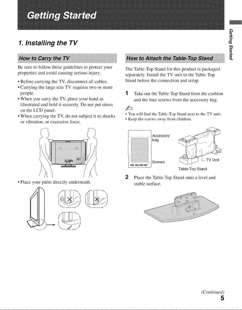
Be sure to follow these guidelines to protect your
properties and avoid causing serious injury.
• Before carrying the TV, disconnect all cables.
• Carrying the large size TV requires two or more
people.
• When you carry the TV, place your hand as
illustrated and hold it securely. Do not put stress
on the LCD panel.
• When carrying the TV, do not subject it to shocks
or vibration, or excessive force.
• Place your palm directly underneath.
The Table-Top Stand for this product is packaged
separately. Install the TV unit to the Table-Top
Stand before the connection and setup.
1 Take out the Table-Top Stand from the cushion
and the four screws from the accessory bag.
• You will find the Table-Top Stand next to the TV unit.
• Keep the screws away from children.
....... Accessory
...... Screws
bag
TV Unit
Table-Top Stand
2 Place the Table-Top Stand onto a level and
stable surface.
cn
o.
i
(Cot_tit_ued)
5

3
Gently slide the TV unit onto the neck of the
Table-Top Stand and align the screws holes.
• When you carry the TV unit, place your hand as
illustrated on page 5 and hold it securely. Do not put
stress on the LCD panel or the frame around the
screen.
• Be careful to not pinch your hands or the AC
power cord when installing the TV unit onto the
Table-Top Stand.
4
Use the supplied screws to attach the TV unit
to the Table-Top Stand (refer to the "Attaching
the Table-Top Stand" flyer).
•If you use an electric screwdriver, set the torque for
tightening at approximately 1.5 N.m {15Kgf.cm}.
Sony strongly recommends taking
measures to prevent the TV from toppling
over. Unsecured TVs may topple and result
in property damage, serious bodily injury
or even death.
Prevent the TV from Toppling
[] Secure the TV to a wall and/or stand.
[] Do not allow children to play or climb on
furniture and TV sets.
[] Avoid placing or hanging items on the TV.
[] Never install the TV on:
• slippery, unstable and/or uneven surfaces.
• furniture that can easily be used as steps, such
as a chest of drawers.
[]
Install the TV where it cannot be pulled,
pushed, or knocked over.
[]
Route all AC power cords and connecting
cables so that they are not accessible to
children.
Use a Sony TV Stand
Use a Sony specified TV stand (see page 2) and
follow the instruction manual provided with the
Sony TV stand.
If a Sony specified TV stand is not used, consider
the following recommended measures.
Recommended Measures to Secure the TV
1 Secure the stand for the TV.
Make sure the TV stand can adequately support the
weight of the TV. Use two angle braces (not
supplied) to secure the stand.
For each angle brace use the appropriate hardware
to:
• Attach one side of the angle brace to the wall stud.
• Attach the other side to the TV stand.
Angle brace
Stand
6

2 Secure the TV to the stand.
Use the optional hardware listed below (not
supplied):
• M6 x 10-12 mm anchor bolt (screwed into the
TV's Table-Top stand).
• A screw or similar (attach it to the TV stand).
• Rope or chain (strong enough to support the
weight of the TV). Make sure that there is no
excess slack in the rope or chain.
An alternative way to secure the TV is with an
optional Sony Support Belt Kit.
Screw
Contact Sony Customer Support to obtain the optional
Support Belt Kit by providing your TV model name.
• For United States call: 1-800-488-7669 or visit:
www.sony.com/accessories
• For Canada call: 1-877-899-7669
3 Anchor the TV to the Wall.
• Measure 2 provides minimal protection against the TV
toppling over. For further protection, follow all three
measures recommended above.
Use the hardware listed below (not supplied):
• Two M6 x 12-18 mm anchor bolts (screw into
the top-most wall-mount holes located on the
rear of the TV).
• Rope or chain (attach to one M6 anchor bolt).
• Wall-anchor (attach to the wall stud) strong
enough to support the weight of the TV (pass
the rope through the wall-anchor, then attach to
the other M6 anchor bolt).
Anchor bolts
_ .....................Rope or
Wall-moun chain
holes
(Continued)
7
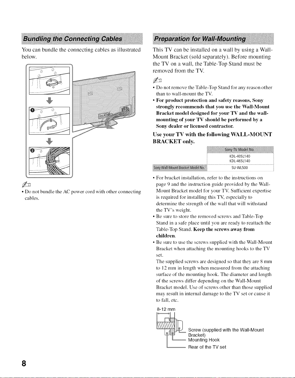
You can bundle the connecting cables as illustrated
below.
• Do not bundle the AC power cord with other connecting
cables.
This TV can be installed on a wall by using a Wall-
Mount Bracket (sold separately). Before mounting
the TV on a wall, the Table-Top Stand must be
removed from the TV.
• Do not remove the Table-Top Stand for any reason other
than to wall-mount the TV.
• For product protection and safety reasons, Sony
strongly recommends that you use the Wall-Mount
Bracket model designed for your TV and the wall-
mounting of your TV should be performed by a
Sony dealer or licensed contractor.
Use your TV with the following WALL-MOUNT
BRACKET only.
KDL-40SL140
KDL-46SL140
• For bracket installation, refer to the instructions on
page 9 and the instruction guide provided by the Wall-
Mount Bracket model for your TV. Sufficient expertise
is required for installing this TV, especially to
determine the strength of the wall that will withstand
the TV's weight.
• Be sure to store the removed screws and Table-Top
Stand in a sate place until you are ready to reattach the
Table-Top Stand. Keep tile screws away from
children.
• Be sure to use the screws supplied with the Wall-Mount
Bracket when attaching the mounting hooks to the TV
set.
The supplied screws are designed so that they are 8 mm
to 12 mm in length when measured from the attaching
sudace of the mounting hook. The diameter and length
of the screws differ depending on the Wall-Mount
Bracket model. Use of screws other than those supplied
may result in internal damage to the TV set or cause it
to fall, etc.
8-12 mm
Screw (supplied with the Wall-Mount
Bracket)
Mounting Hook
Rear of the TV set
8

Follow the simple steps below to remove the Table-
Top Stand:
1 Disconnect all the cables from the TV.
2 Remove the four screws from behind the TV as
indicated below. Do not remove any other
screws from the TV.
3 Gently lay the TV (face down) onto a level and
stable surface covered with a thick and soft
cloth.
4 Secure the Mounting Hooks to the rear of the
TV. For more details refer to Install the Wall-
Mount Bracket and also the instruction guide
provided by the Wall-Mount Bracket model for
your TV.
• If an electric screwdriver is used, set the torque to
tighten at approximately 1.5 N.m {15Kgf.cm}.
_i_i_i_i_iiiiiiiiiiiiiiiiiiiiiiili_iiiiiiiiiiiiiiiiiiili_iiiiiiiiiiiiiiiiiiiiiiii!i!ii!i_i_i_i_i_i_i_i_i_i_i_i!i_&i_i_ii!i_ii_ii_ii_ii_i_iiii_i_Siii_ii_iiiiiii_ii_iiiiiii_ii_iiiiiii_ii_ii_iiii_i_i_iiiiiii_ii_ii_iiii_i_i_iii_ii_i_iii_ii_i_iii_ii_i_ii_ii_i_iii_i_i_iii_ii_i_iii__Siii_ii_ii_iiii_i_i_iiiiiii_ii_iiiiiii_ii_iiiiiii_i_Siii_ii_iiiiiii_ii_iiiiiii_iSii_ii_iiiiiii_i_i_iiiiiii_iSii_i_i_iiiiiii_i_i_iii_ii_i_iii_ii_i_iii_ii_i_iii_ii_i_iii_ii_i_iii_ii_i_iii_ii_i_iii_ii_i_iii_ii_i_i_i_
To Customers
Your KDL-40SL140/KDL-46SL140 can be
wail-mounted using a Wall-Mount Bracket (sold
separately). See table on page 8 showing the Wall-
Mount Bracket model appropriate for your TV.
For product protection and safety, Sony strongly
recommends that you use the Wall-Mount
Bracket designed for your TV and wall-
mounting is performed by a Sony dealer or a
licensed contractor. Do not attempt to install it
yourself. Sony is not liable for any damage or
injury caused by mishandling or improper
installation.
Please provide your licensed contractor with this
installation information as well as instructions
supplied with the Wall-Mount Bracket.
t_
o.
To Sony Dealers and Licensed Contractors
To avoid injury and property damage, read these
instructions carefully. Periodic inspection and
maintenance is highly recommended to ensure that
TV is securely mounted.
Installing the Wall-Mount Bracket and
Mounting Hooks
1 Open the Wall-Mount Bracket package and
check for all the required parts including the
instruction.
9 See the Installation Dimensions Table on
page 10 to determine the best location for wall-
mounting. The wall must be strong enough to
support at least four times the weight of the
TV. Also refer to the instruction provided with
your Wall-Mount Bracket.
(Continued)
9
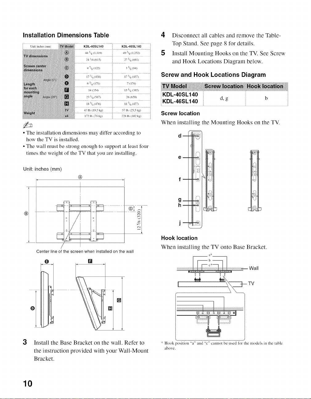
Installation Dimensions Table
44 1/8 (I,119)
24 1/4 (615)
4 7/8 (122)
17 1/4(438)
63/4(171)
14 (354)
23 1/8(587)
18 314(476)
4_ lb. ( 19.5 kg)
172 lb. (78 kg)
• The installation dimensions may differ according to
how the TV is installed.
• The wall must be strong enough to support at least four
times the weight of the TV that you are installing.
49 318(1,252)
27 114(691 )
3 318(84)
17 1/4(437)
7(176)
15 1/4(_85)
26 (659)
18 7/8 (477)
57 lb (25,5 kg)
228 lb. (102 kg)
4 Disconnect all cables and remove the Table-
Top Stand. See page 8 for details.
5 Install Mounting Hooks on the TV. See Screw
and Hook Locations Diagram below.
Screw and Hook Locations Diagram
KDL-40SL140
Screw location
When installing the Mounting Hooks on the TV.
d,g
Unit: inches (mm)
®
Center line of the screen when installed on the wall
[]
3
Install the Base Bracket on the wall. Refer to
the instruction provided with your Wall-Mount
Bracket.
, i_'ii
Hook location
When installing the TV onto Base Bracket.
a*
':' Hook _osition "a" and "c" cannot be used lor the models in the table
above.
10

Make sure that your TV has adequate air
circulation. Allow enough space around the TV as
shown below.
Installed on the wall
...... ......
_/ (30 cm)
4 inches
.. :: i I ] i4)_nc!?es
(10 cm)
iq Kilo cmi ............
i I I i Leave at least
i I I I; ......this much
i [ _ I ', space around
i................... __4_i_n__cb_e__s__!_o__c__m)j the set.
Installed with stand
11 7/8 inches
==
4inches_I I i4inchosr_ __£_!_hos
I1_- (6crn)
£b
Leave at least this much space around the set,
Never install the TV set as follows:
Air circulation is blocked. Air circulation is blocked.
• Inadequate air circulation can lead to overheating of the
TV and may cause damage to your TV or cause fire.
11

1
Locating Inputs and Outputs
Rear of TV
"___
[]
Side panel
12

S VIDEO
S VIDEO which provides better picture quality than composite video. The S VIDEO does not
provide sound; you will need to connect the audio cables.
t_
VIDEO IN 1/2/3 Connects to the composite video and audio output jacks on your A/V equipment such as a
VIDEO/ DVD player or other video equipment. VIDEO IN 2 input is located on the left side panel of
L(MONO)- the TV.
AUDIO-R
[] c6MPONENT Connects to your DVD player's or digital set:top h0x;s component video (YPBPR) and audio
IN 112 (1080ii (L/R) jacks. Component videool_ovides better picture quality than the S VIDEO or the
720p1480p1480i)l composite video connections (111).
L-AUDIO-R
[] PC iN ...... Connects to a personal computer;s video output connector using an HDi5 HDi5 cahie
(RGB/AUDIO) (analog RGB, not supplied).
See "PC Input Signal Reference Chart" on page 16 for the signals that can be displayed.
• For some Apple Macintosh computers, it may be necessary to use an adapter (not supplied). If
this is the case, connect the adapter to the computer before connecting the HD15-HD 15 cable.
[] HDMIiN 1/2/3/4 HDMI (High-Definition Muhimedia Interface) provides an uncompressedl aii-digital
R-AUDIO-L audio/video interface between this TV and any HDMI-equipped A/V equipment. HDMI
supports enhanced, or high-defnition video, plus digital audio.
If the equipment has a DVI jack and not an HDMI jack, connect the DVI jack to any
HDMI IN (with DVI-to-HDMI cable or adapter)jack, and connect the audio jack to the
AUDIO IN (L/R) jacks below the HDMI IN 4.
DVI-to-HDMI cable DVI-to-HDMI adapter Audio cable
• Be sure to use only an HDMI cable that bears the HDMI logo.
• When connecting a DVI-equipped PC to an HDMI jack, also connect an Audio cable
between the PC and R-AUDIO-L jack.
• The HDMI input has been fitted to suit A/V equipment such as DVD players for 480i, 480p,
720p, 1080i and 1080p signals. PC generated signals may not be rendered as expected due to
scaling factors. For better PC view, use the PC IN (RGB IN) input. Note that this TV
displays all video input signals in a resolution of 1,920 dots x 1,080 lines.
[] DiGiTAL AuDio Connects to the optical audio input of a digitai audio equipment that is PCM compatihie .....................
OUT (OPTICAL)
[] AuDio OUT Connects to the ieft and right audio input jacks of your audio or video equipmentl You can use
(VAR/FIX) these outputs to listen to your TV's audio through your stereo system.
L-AUDIO-R
• Audio Out level is VARIABLE while Speakers are On, when Speakers control is turn
Off the level in the Audio Out is FIXED (see page 31).
[] cABL_ .............RF input that connects to your cable or VHF/UHF antenna ..........................................................................................................................................................................................................
ANTENNA
• Component video (YPBPR) connection are necessary to view 480i, 480p, 720p and 1080i video formats.
• HDMI input supports signals up to 1080p.
• 1080p format can only be supported through HDMI inputs.
• This TV displays all video input signals in a resolution of 1,920 dots x 1,080 lines.
13
3. Connecting the TV
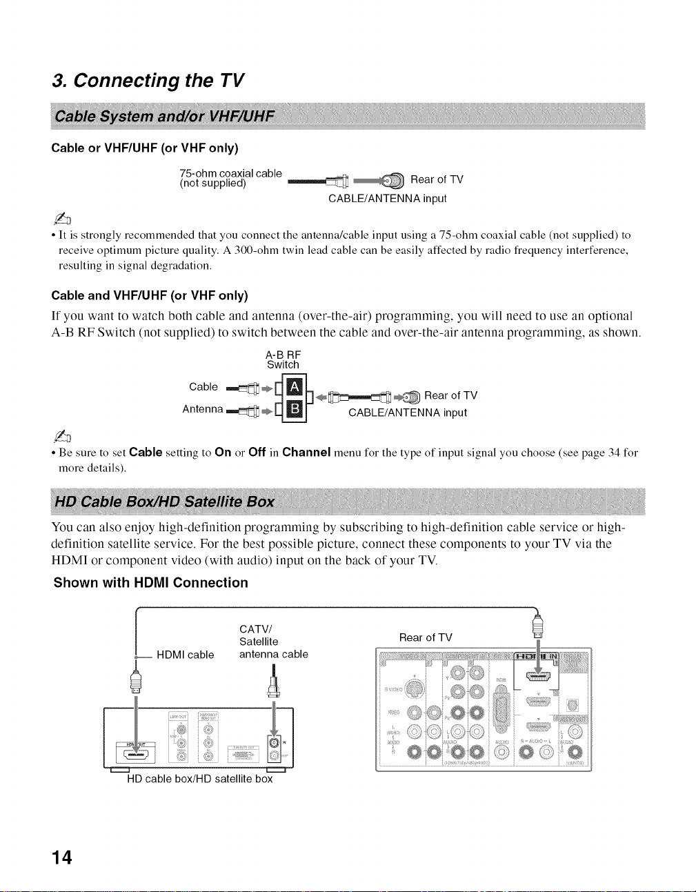
Cable or VHF/UHF (or VHF only)
75-ohm coaxialcable
(not supplied)
CABLE/ANTENNA input
• It is strongly recommended that you connect the antenna/cable input using a 75-ohm coaxial cable (not supplied) to
receive optimum picture quality. A 300-ohm twin lead cable can be easily affected by radio frequency interference,
resulting in signal degradation.
Cableand VHF/UHF (or VHF only)
If you want to watch both cable and antenna (over-the-air) programming, you will need to use an optional
A-B RF Switch (not supplied) to switch between the cable and over-the-air antenna programming, as shown.
A-B RF
Switch
Cable ,,,_ _ [_'_
Rearof TV
D RearofTV
Antenna_ ÷ LL_ CABLE/ANTENNA input
• Be sure to set Cable setting to On or Off in Channel menu for the type of input signal you choose (see page 34 for
more details).
You can also enjoy high-definition programming by subscribing to high-definition cable service or high-
definition satellite service. For the best possible picture, connect these components to your TV via the
HDMI or component video (with audio) input on the back of your TV.
Shown with HDMI Connection
L CATV/
HDMIcable antenna cable
Satellite
._
Rear of TV
21
HD cable box/HD satellite box
14
 Loading...