

Sony KDL-46EX650 Schematic
Self Diagnosis
HISTORY INFORMATION FOR THE FOLLOWING MANUAL:
Supported model
SERVICE / TRAINING MANUAL
AZ3F Chassis
ORIGINAL MANUAL ISSUE DATE: 5/2012
Version Date Subject
1.0 05/7/2012 Original Manual Release Date
Segment: P-2A
LCD Digital Color TV
9-883-881-01
Self Diagnosis
Supported model
SERVICE / TRAINING MANUAL
AZ3F Chassis
Segment: P-2A
KDL-32EX650
LCD Digital Color TV
9-883-881-01
MODEL LIST
MODEL COMMANDER DESTINATION MODEL COMMANDER DESTINATION
KDL-32EX650 RM-YD077 LA/MX
KDL-46EX650 RM-YD077 LA/MX
KDL-32EX651 RM-YD077 LA/MX
KDL-40EX650 RM-YD077 LA/MX
KDL-40EX651 RM-YD077 LA/MX
KDL-46EX651 RM-YD077 LA/MX
9-883-881-01
TABLE OF CONTENTS
Cautions and Warnings ..................................................................................iii
Section 1 - Features and Overview ................................................................1
Features ........................................................................................................1
Specications ................................................................................................1
Checking the Accessories .........................................................................2
Chassis Overview .......................................................................................... 3
Overall Circuit Description ............................................................................. 4
Main Board ...............................................................................................4
Power Supply Board ................................................................................. 4
IR Board .................................................................................................... 4
Switch Unit ................................................................................................ 5
LCD Panel Assembly ................................................................................5
Section 2 - Troubleshooting ...........................................................................6
Overview .......................................................................................................6
Updating the Software ..............................................................................6
Self Diagnosis Function ................................................................................. 6
Standby LED Blink Count .........................................................................6
Viewing the Self Check Diagnosis History ................................................ 7
Triage Chart ...................................................................................................9
Section 3 - Flow Charts and Diagrams ........................................................10
Block Diagram .............................................................................................10
No Power ................................................................................................ 11
Standby LED Blinking ............................................................................. 13
No Picture ............................................................................................... 14
Section 4 - Disassembly/Part Number Information ....................................16
Table-Top Stand Removal ...........................................................................16
Rear Cover Removal ................................................................................... 17
Handling the LVDS FFC Connector .............................................................18
Disconnecting the LVDS FFC Connector ...............................................18
Connecting the LVDS FFC Connector .................................................... 18
Main Board (BAPS) and Power Supply Board (GL2/GL4) Removal ........... 19
Panel Brackets and LCD Panel Removal .................................................... 20
Cleaning the LCD Panel .........................................................................20
Connectors ..................................................................................................21
Screws ......................................................................................................... 21
Accessories and Packaging ........................................................................22
Miscellaneous .............................................................................................. 22
Optional Accessories ...................................................................................22
Wire Dressing .............................................................................................. 23
Section 5 - Updates and Adjustments .........................................................24
Overview .....................................................................................................24
Software Updates for Customers ................................................................24
Software Updates for Servicers ................................................................... 24
Software Update Responsibility .............................................................. 25
Checking the Software Version ...............................................................25
Completing Service Requirements
When Replacing the Main Board ................................................................. 25
Updating the Software ............................................................................25
Selecting the Segment Code .................................................................. 26
Selecting the Destination ........................................................................ 28
Selecting the Model Name ...................................................................... 29
Adding the Serial Number ....................................................................... 29
Conrming the Model ID and Product ID ................................................ 31
Clearing the Self Diagnosis Self Check Information ............................... 32
KDL-32EX650/32EX651/40EX650/40EX651/46EX650/46EX651 i
Resolving an 8 Blink Error ........................................................................... 33
Verifying There is an 8x Error .................................................................34
Resetting the TV to Factory Condition ....................................................34
Updating the Software ............................................................................34
Replacing the Main Board ......................................................................34
Completing Service Requirements When
Replacing the LCD Panel or TCON Board .................................................34
Updating the Software ............................................................................35
Conrming the Model ID and Product ID ................................................ 35
Resetting the Panel Operation Time .......................................................36
Clearing the Self Diagnosis Self Check Information ............................... 37
Optional Adjustments ..................................................................................38
Enabling VCOM to Adjust the Picture .....................................................38
Setting White Balance Adjustments ........................................................39
Resetting the TV to Factory Condition .........................................................39
Resetting the TV to Factory Condition Using Service Mode ................... 39
TABLE OF CONTENTS
Appendix A: Encryption Key Components ...............................................A-1
KDL-32EX650/32EX651/40EX650/40EX651/46EX650/46EX651 ii

CAUTIONS AND WARNINGS
CAUTION
These servicing instructions are for use by qualied service personnel only.
To reduce the risk of electric shock, do not perform any servicing other than
that contained in the operating instructions unless you are qualied to do so.
WARNING!!
An isolation transformer should be used during any service to avoid possible
shock hazard, in case of live chassis.
!
SAFETY-RELATED COMPONENT WARNING!!
There are critical components used in LCD color TVs that are important for
safety. These components are identied with shading and
schematic diagrams and the parts list. It is essential that these critical parts
be replaced only with the part number specied in the parts list to prevent
electric shock, re, or other hazard.
!
mark on the
NOTE: Do not modify the original design without obtaining written permission
from the manufacturer or you will void the original parts and labor warranty.
KDL-32EX650/32EX651/40EX650/40EX651/46EX650/46EX651 iii
CAUTIONS AND WARNINGS
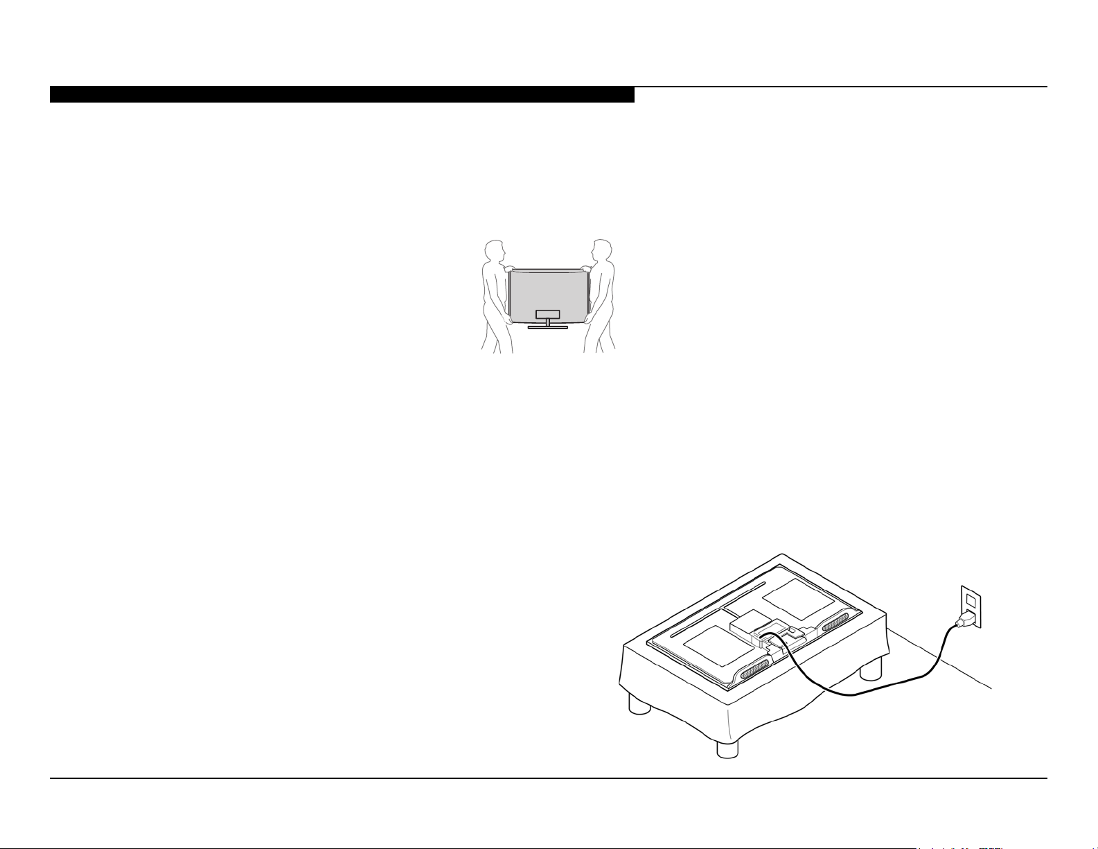
SETTING UP AND CARRYING THE TV
● Disconnect all cables when carrying the TV.
● Carry the TV with the adequate number of people; larger size TVs require two or more people.
● Correct hand placement while carrying the TV is very important for safety and to avoid damage.
USE CAUTION WHEN HANDLING THE LCD PANEL
When repairing the LCD panel, be sure you are grounded by using a wrist band.
When installing the LCD panel on a wall, the LCD panel must be secured using the 4 mounting holes on the rear cover.
1. Do not press on the panel or frame edge to avoid the risk of electric shock.
2. Do not scratch or press on the panel with any sharp objects.
3. Do not leave the module in high temperatures or in areas of high humidity for an extended period of time.
4. Do not expose the LCD panel to direct sunlight.
5. Avoid contact with water. It may cause a short circuit within the module.
6. Disconnect the AC power when replacing the backlight or inverter circuit.
(High voltage occurs at the inverter circuit at 650Vrms.)
7. Always clean the LCD panel with a soft cloth material.
8. Use care when handling the wires or connectors of the inverter
circuit. Damaging the wires may cause a short.
9. Protect the panel from ESD to avoid damaging the electronic
circuit (C-MOS).
10. During the repair, DO NOT leave the Power On for more than
1 hour while the TV is face down on a cloth.
KDL-32EX650/32EX651/40EX650/40EX651/46EX650/46EX651 iv
CAUTIONS AND WARNINGS
CLEANING THE LCD PANEL
CAUTION: When cleaning the TV, be sure to unplug the power cord to avoid any chance of electric shock.
Clean the cabinet of the TV with a dry soft cloth.
Wipe the LCD screen gently with a soft cloth.
; Stubborn stains may be removed with a cloth slightly moistened with a solution of mild soap and warm water.
; If using a chemically pretreated cloth, please follow the instruction provided on the package.
; Never use strong solvents such as a thinner, alcohol or benzine for cleaning.
; Periodic vacuuming of the ventilation openings is recommended to ensure proper ventilation.
; Do Not use paper towels, any type of abrasive pad, rags, rubber or vinyl materials to clean the screen. Using these materials could easily scratch the
screen which may result in permanent damage.
; Do Not use any cleaning product containing alkaline/acid cleaner, scouring powder, or volatile solvent, such as alcohol, ammonia, benzine, thinner or
insecticide. Using any of these harsh cleaners may result in permanent damage to the screen.
; Do Not spray water or detergent directly onto the TV screen . If liquid drips into the bottom of the screen it may cause a failure.
KDL-32EX650/32EX651/40EX650/40EX651/46EX650/46EX651 v
CAUTIONS AND WARNINGS
To Exposed Metal
Parts on Set
0.15 µF
Earth Ground
AC
Voltmete
r
(0.75V)
Trouble Light
SAFETY CHECK-OUT
After correcting the original service problem, perform the following safety
checks before releasing the set to the customer:
1. Check the area of your repair for unsoldered or poorly soldered
connections. Check the entire board surface for solder splashes
and bridges.
2. Check the interboard wiring to ensure that no wires are “pinched” or
touching high-wattage resistors.
3. Check that all control knobs, shields, covers, ground straps, and
mounting hardware have been replaced. Be absolutely certain that
you have replaced all the insulators.
4. Look for unauthorized replacement parts, particularly transistors,
that were installed during a previous repair. Point them out to the
customer and recommend their replacement.
5. Look for parts which, though functioning, show obvious signs of
deterioration. Point them out to the customer and recommend their
replacement.
6. Check the line cords for cracks and abrasion. Recommend the
replacement of any such line cord to the customer.
7. Check the antenna terminals, metal trim, “metallized” knobs,
screws, and all other exposed metal parts for AC leakage. Check
leakage as described in “Leakage Test”.
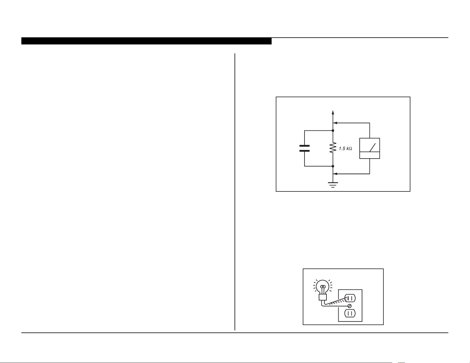
LEAKAGE TEST
3. Measuring the voltage drop across a resistor by means of a VOM
or battery-operated AC voltmeter. The “limit” indication is 0.75 V, so
analog meters must have an accurate low voltage scale. Nearly all
battery-operated digital multimeters that have a 2 VAC range are
suitable. (see Figure A)
Figure A. Use an AC voltmeter to check AC leakage.
HOW TO FIND A GOOD EARTH GROUND
The cover-plate retaining screw on most AC outlet boxes is at earth ground.
Verify the AC outlet box retaining screw ground by connecting a 60W to
100W incandescent (not a neon or uorescent lamp) between the hot side of
the receptacle and the retaining screw. Try both slots, if necessary, to locate
the hot side on the line; the lamp should light at normal brilliance if the screw
is at ground potential. (see Figure B)
KDL-32EX650/32EX651/40EX650/40EX651/46EX650/46EX651 vi
The AC leakage from any exposed metal part to earth ground and from all
exposed metal parts to any exposed metal part having a return to chassis,
must not exceed 0.5 mA (500 microamperes). Leakage current can be
measured by any one of three methods.
1. A commercial leakage tester.
Follow the manufacturers’ instructions provided with the tester.
2. A battery-operated AC milliammeter.
AC Outlet Box
Figure B. Checking for earth ground.
SECTION 1 - FEATURES AND OVERVIEW
FEATURES
The AZ3F chassis is one of several designs for the 2012 model line of Sony
Bravia® LCD televisions. This manual covers the following models:
KDL-32EX650
KDL-32EX651
KDL-40EX650
KDL-40EX651
KDL-46EX650
KDL-46EX651
The BRAVIA® EX65x series LED LCD HDTVs have incomparable picture
quality and an ultra-thin design
● Brilliant Full HD (1080p) picture quality
● X-Reality™ Engine that creates crisp detail in each scene
● Bright picture & thin design with Edge LED backlight
● One-touch access to the Sony Entertainment Network™ and apps1
● Skype™ ready1
● PC and tablet content2 on your TV w/ Intelligent Connect
● Media Remote™ app to control your TV with a smartphone
● Wi-Fi® adaptor included to stream HD entertainment.
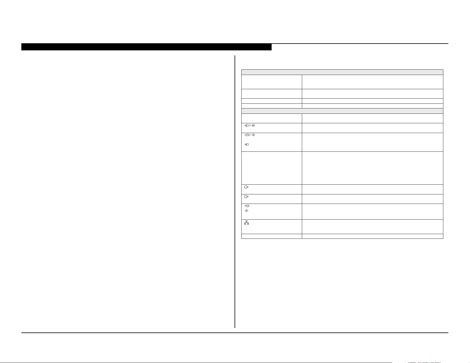
SPECIFICATIONS
Sistema
Sistema de TV NTSC: Norma de TV americana
Cobertura de canales Terrestre analógico: 2 - 69 / Terrestre digital: 2 - 69
Sistema del panel Panel LCD (pantalla de cristal líquido)
Salida de bocinas 10 W + 10 W
Tomas de entrada/salida
CABLE/ANTENNA
(Cable/Antena)
VIDEO IN 1
(Entrada de video 1)
COMPONENT IN
VIDEO IN 2
(Entrada de video 2)
HDMI IN 1/2/3/4
Entrada HDMI 1/2/3/4
AUDIO OUT (Salida de
audio)/Auriculares
DIGITAL AUDIO OUT
(O PTICAL)
PC IN (Entrada de PC)
PC/HD MI 2 AUDIO IN
(Entrada de audio de PC/HDMI 2)
2
LA NConector 10BASE-T/100BASE-TX (La vel ocidad de la conexión podría variar en
USB/DLNA Consulte el i-Manual para el formato compatible.
ATSC (8VSB terrestre): 8VSB compatible con ATSC
QAM por cable: ANSI/SCTE 07 2000 (No incluye la funcionalidad CableCARD)
Cable analógico: 1 - 135 / Cable digital: 1 - 135
Terminal externa de 75 ohms para entrada de señal de radiofrecuencia
Entrada de video/audio (izquierda-derecha)
(video componente): 1,080p (60 Hz), 1,080i (60 Hz), 720p (60 Hz), 480p, 480i
YP
BPR
Entrada de audio (izquierda-derecha)
Entrada de video (contacto común de componente)
Video: 1,080p (30, 60 Hz), 1,080/24p, 1,080i (60 Hz), 720p (30, 60 Hz), 720/24p,
480p, 480i, Formatos de PC
Audio: PCM lineal de dos canales: 32; 44,1 y 48 kHz, 16, 20 y 24 bits, Dolby Digital
Entrada de audio analógico (minitoma estéreo) (sólo HDMI IN 2, común con PC IN
[entrada de PC])
ARC (sólo HDMI IN 1)
Minitoma estéreo
Toma óptica digital (PCM lineal de dos canales, Dolby Digital)
RGB analógico (Conector D-sub de 15 pines)
Entrada de audio (minitoma estéreo) (común con HDMI IN 2)
función del entorno de red. No se garantizan la tasa de comunicación ni la
calidad de
comunicación 10BASE-T/100BASE-TX para este TV.)
1. Broadband speed of at least 2.5 Mbps recommended (10 Mbps for HD). Content subject
to change and may require fees. Skype requires CMU-BR100 camera sold sep. Subject to
Skype’s terms and conditions.
2. Requires devices connected to the same wireless home network.
KDL-32EX650/32EX651/40EX650/40EX651/46EX650/46EX651 1
SECTION 1 - FEATURES AND OVERVIEW
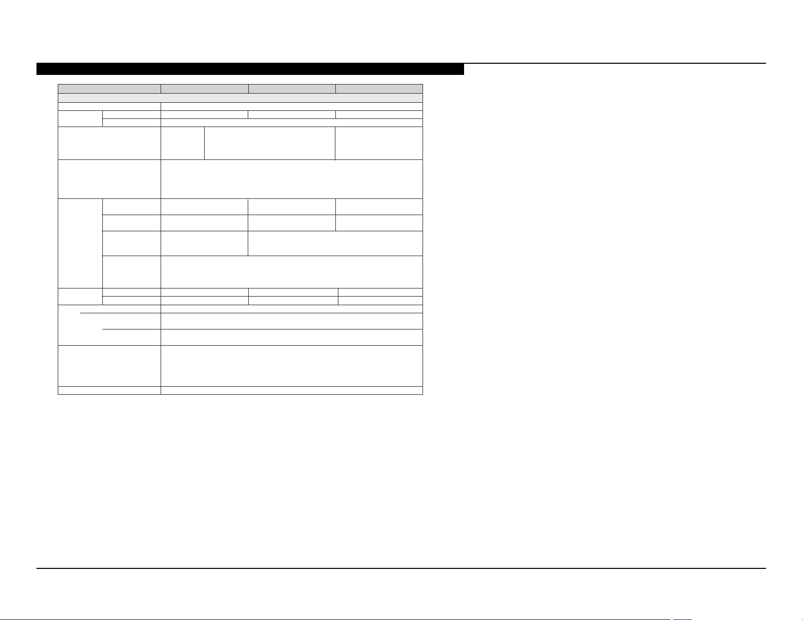
1
Nombre del modelo KDL- 46EX65x 40EX65x 32EX65x
Alimentación y otras especicaciones
Requisitos de al imentación 110-240 V ca, 50/60 Hz (EE. UU./Canadá 120 V ca, 60 Hz)
Consumo de
potencia
Tamaño de pantall a* (cm)
(pulgadas medidas
diagonal mente)
Resolución del monitor 1 920 puntos (horizontal) × 1 080 líneas (vertical)
Dimensiones *
Pe so* con soporte (kg) 16,4 13,6 9,7
Accesorios suministrados Consulte
Accesorios opcionales
(no suministrados)
Temperatura de funcionamient o0 ºC – 40 ºC
*El tamaño, las dimensiones y el peso de la pantalla son valores aproximados.
en uso 111W 104W
en espera Menos de 0,15 W con 120 V ca y menos de 0,3 W con 240 V ca
116,8
46 pulgadas
con soporte (mm) 1 074 × 669 x 241
sin soporte
patrón de oricios
de montaje mural
(mm)
tamaño de
tornillos de
montaje mural
(mm)
sin soporte (kg) 14,1 11,3 7,8
Control remoto
Modelo
Requisitos de
alimentación
(mm) 1 074 × 651 x 60
300 × 300 200 × 20 0
M6 (8-12 mm)
RM-YD077
3 V cc ( 2 Pilas tipo AAA)
Cables de conexión
Kit de correa de soporte
Soporte de montaje mural : SU-WL500
Unidad de cámara y micrófono: CMU-BR100
Adaptador de LAN inalámbrica USB: UWA-BR100
101,6
40 pulgadas
(Vericación de los accesorios)
941 × 595 × 241 753 × 490 × 226
941 × 576 × 60 753 × 472 × 60
74W
80,1
31,5 pulgadas
(32 clase)
• La disponibilidad de los accesorios opcionales dependerá de los países, regiones, modelo del TV
y de las existencias.
• El diseño y las especicaciones están sujetos a cambios sin previo aviso.
CHECKING THE ACCESSORIES
Control remoto (1)*
Pilas de tamaño AAA (2)
Soporte de sobremesa (1)*
Tornillos de jación para el soporte de
sobremesa (M5 × 16) (3)
Tornillos de montaje para el soporte de
sobremesa (M5 x 16) (2)
Manual de instrucciones (este manual) y
otros documentos
*1Consulte la tabla de Especicaciones al nal de
este manual.
2
*
Se requiere ensamblar la base de soporte de
sobremesa. Para ensamblar la base de soporte
de sobremesa consulte el follet o suministrado.
2
KDL-32EX650/32EX651/40EX650/40EX651/46EX650/46EX651 2
SECTION 1 - FEATURES AND OVERVIEW
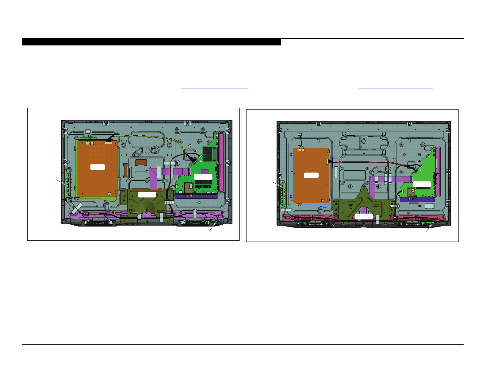
CHASSIS OVERVIEW
The primary circuits in the AZ3F chassis consist of a Main Board (BAPS Board), Power Supply Board (GL2 Board for 32” models, and GL4 Board for 40” & 46”
models), the IR Board (HL Board), the Switch Unit, and the LCD Panel Assembly which includes the TCON Board.
NOTE: For connector part number information, refer to “Connectors” on page 21. For Wire Dressing information, refer to “Wire Dressing” on page 23.
GL2
SWITCH
UNIT
TCON
BAPS
SWITCH
UNIT
GL4
BAPS
TCON
HL
BOARD LAYOUT FOR KDL-32EX650/32EX651 ONLY
HL
BOARD LAYOUT FOR KDL-40EX650/40EX651/46EX650/46EX651 ONLY
KDL-32EX650/32EX651/40EX650/40EX651/46EX650/46EX651 3
SECTION 1 - FEATURES AND OVERVIEW
OVERALL CIRCUIT DESCRIPTION
“Block Diagram” on page 10 provides an overview of the AZ3F
chassis. The following are descriptions of the boards and their functions.
MAIN BOARD
Common to all models the Main Board, designated as the BAPS Board,
contains the TV control, video, and audio processing circuitry. All these
functions are accomplished using the X-Reality Processor IC9000.
TUNER
The tuner is a combination ATSC/NTSC unit. It can receive traditional
analog NTSC signals via cable or terrestrial along with ATSC digital
signals via terrestrial (8VSB) or cable (64 or 256 QAM).
X-REALITY PROCESSOR
IC9000 performs the majority of the necessary audio and video
processing on the Main Board.
TV Microprocessor: The CPU internal to the X-Reality processor
controls all aspects of the television functions. Input from the user
along with monitoring of critical circuits is also performed by this CPU.
Digital Audio and Video Decoder: The MPEG2 and Digital Dolby
audio streams are received from the tuner for decompression. All video
sources which are not native 1920 X 1080p 60HZ are scaled to this
resolution. Digital audio content is output to the class D amplier for
processing and amplication.
HDMI Input and Switching: The customer can select the HDMI1,
HDMI2, HDMI3, HDMI4 input via the HDMI switch IC5500. Each HDMI
input contains a common EDI NVM (internal to IC5500) to provide
display information data to any device connected via the HDMI inputs.
LVDS Transmitter: Integrated into IC9000 is a Low Voltage Differential
Signaling (LVDS) transmitter. This circuit converts the 8-bit parallel
RGB video information into a set of high speed serial lines for noisefree transmission to the TCON Board circuits located internally to the
LCD Panel.
Scan Converter: Signal processing circuit that performs resolution
conversion (aspect ratio) and interlaced to progressive scan (IP)
conversion.
AUDIO AMPLIFIER
The main speaker audio amplier (IC4601) and sub-woofer amplier
(IC4701) amplies the digital audio output of the X-Reality processor and
sends it to the speakers.
TEMPERATURE SENSOR
The temperature sensor detects over-temperature conditions on the Main
Board, LCD Panel, or ambient room temperature and sends the shutdown
signal to the processor.
POWER SUPPLY BOARD
There are different Power Supply Boards used in the models in this
manual. The type of board depends on the size of LCD panel. They are:
● GL2 Board (for 32” models)
● GL4 Board (for 40” and 46” models)
There are 3 distinct sections on the power supply:
Standby Supply: Continuously operational as long as AC power is
applied, the standby supply generates 3.3V for the circuits requiring power
while the unit is turned off. An unregulated 19V line is present to provide
power to the main relay, PFC and main power supply at turn-on.
Main Supply: Once the power supply receives a power-on command
from the CPU on the Main Board, the main switching supply is turned on
to provide a regulated 12V source and Audio 12V.
Converter: Generates the B+ and B- voltages for the LED backlights.
IR BOARD
Designated as the HL Board, the IR Board contains the power, standby,
and timer LED’s that are located on this board along with the IR remote
receiver and light level sensor.
KDL-32EX650/32EX651/40EX650/40EX651/46EX650/46EX651 4

SECTION 1 - FEATURES AND OVERVIEW
SWITCH UNIT
This board contains the power, channel and volume up/down, and menu
buttons.
LCD PANEL ASSEMBLY
The LCD Panel Assembly includes the LCD Panel, TCON Board, and LED
Backlight system.
The LCD Panel contains the actual liquid crystals, color lters, and
polarizers. The liquid crystals are manipulated by the applied voltage to
pass a specic amount of light - from the backlite - depending on the level
of voltage applied.
The TCON performs all the control, timing, charge, and discharge functions
driving the operation of the LCD Panel.
A new LCD Panel assembly from parts will include the following items.
● LCD Panel
● TCON Board
● LED Backlighting Components (varies)
TCON BOARD
The TCON Board communicates between the LCD Panel and the
microprocessor on the Main Board.
NOTE: The TCON Board is not available as a replacement part for all
models. To determine if the TCON Board is available as a replacement
part, refer to the LCD Panels Manual.
KDL-32EX650/32EX651/40EX650/40EX651/46EX650/46EX651 5
SECTION 2 - TROUBLESHOOTING
Self Diagnosis
Supported model
OVERVIEW
This chapter provides information regarding the Self Diagnosis feature in
our TVs.
UPDATING THE SOFTWARE
The Self Diagnosis function is designed to provide information regarding
the problem with the TV, however, there are several issues that may be
resolved by updating the TV software to the latest version. Always check
the Sony site for any issues that are software related. Most symptoms that
are correctable by software updates involve communications issues with
other devices or minor glitches in the operation of a specic function. Below
is a list of some of the symptoms that may be corrected with a software
update:
● Fluctuations in picture brightness
● Intermittent picture freezing or noise
● Problems with certain inputs (especially HDMI)
● Intermittent or distorted audio
● Erratic remote control operation
● TV turns on and off by itself
● Loss of color
● Internet connectivity
● Certain features not working correctly
(photo or video le viewing)
SELF DIAGNOSIS FUNCTION
Critical voltages and circuit operations are monitored by the CPU on the
Main Board. If an error is detected the Self Diagnosis function in the TV will
force the TV to shut down by the CPU. The monitored circuit in which the
fault occurred will automatically cause the CPU to blink the Standby LED
in groups of repeating sequences. The number of times the Standby LED
blinks indicates the possible cause of the problem.
Not all of the available protect codes are used in every model. For example,
models that don’t have the local dimming feature do not use the 4X blink
error as this circuit is found in models that are backlit with uorescent lamps.
The information in this section provides guidance in locating the possible
component causing the shutdown.
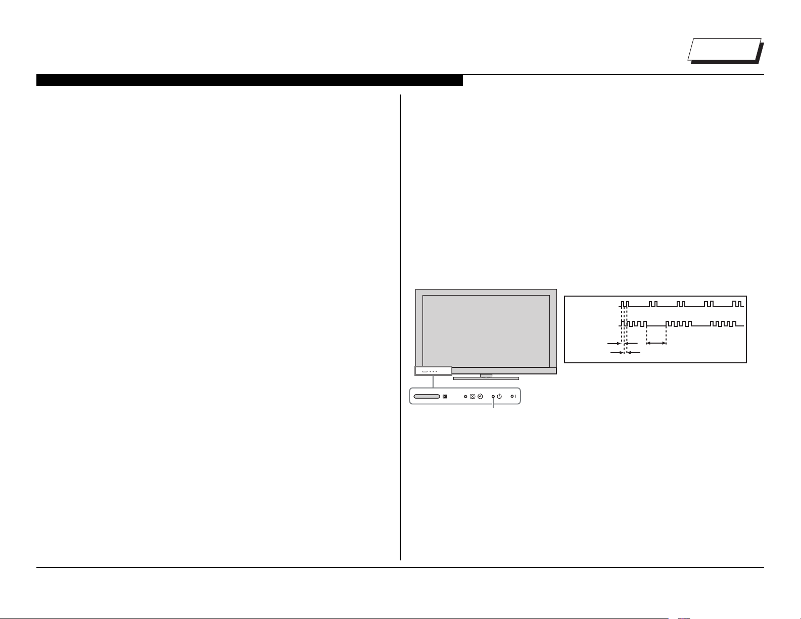
STANDBY LED BLINK COUNT
2 times
5 times
Standby LED
LED ON 0.3 sec.
LED OFF 0.3 sec.
LED DISPLAY & BLINK COUNT
LED OFF
3 sec.
KDL-32EX650/32EX651/40EX650/40EX651/46EX650/46EX651 6
SECTION 2 - TROUBLESHOOTING
StandBy LED
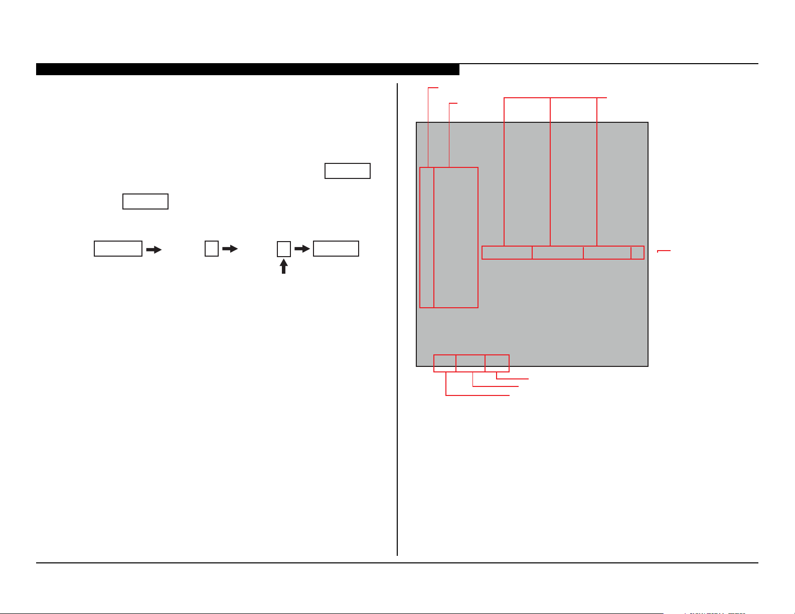
VIEWING THE SELF CHECK DIAGNOSIS HISTORY
When an error is detected, the Self Check screen records the date(s) and
the number of times the error occurred. This is helpful in conrming past
occurrences of an error, and for determining if an error is intermittent when
the customer is not sure what is causing the television to shut down. If the
screen displays a “0”, no error has occurred.
1. Take the TV out of deep Standby mode by pressing
turn on the TV.
POWER
to turn the TV back off.
Channel 5 Volume -
POWER
2. Press
3. Press the following buttons on the Remote Commander within a
second of each other:
DISPLAY
* NOTE: This differs from accessing Service Adjustments Mode
(Volume +)
POWER
to
Blink Count
Diagnosis
Item
SELF CHECK
000 RESERVED --------------------- ------------------------------------------ 00
000 RESERVED --------------------- ------------------------------------------ 00
002MAIN_POWE --------------------- ------------------------------------------ 00
003 DC_ALERT --------------------- ------------------------------------------ 00
003 AUD_PROT --------------------- --------------------- ---------------------00
003 HDMI_EQ --------------------- --------------------- --------------------- 00
003 TU_DEMOD --------------------- ------------------------------------------ 00
004 VLED --------------------- ------------------------------------------00
004 LD_ERR --------------------- --------------------- ---------------------00
005 HFR_ERR --------------------- --------------------- ---------------------00
005 TCON_ERR120123132522 120123113645--------------------- 02
005 P_ID-ERR --------------------- --------------------- --------------------- 00
006 BACKLITE --------------------- ------------------------------------------00
007 TEMP_ERR --------------------- ------------------------------------------ 00
007 FAN_ERR --------------------- ------------------------------------------ 00
010 EMITTER --------------------- --------------------- ---------------------00
101 VPC_WDT --------------------- ------------------------------------------ 00
102 MEPS_WDT--------------------- ------------------------------------------ 00
103 HOST_WDT --------------------- ------------------------------------------00
104 STBY_WDT --------------------- ------------------------------------------ 00
00345 000333 06789
Panel operation time by hour (MAX:65535)
Panel operation time by hour (MAX:65535)
Boot count (MAX:65535)
Boot count (MAX:65535)
Total operation time by hour (MAX:65535)
Total operation time by hour (MAX:65535)
*Format of Error History = YYMMDDhhmmss example 120123132522= Jan 23, 2012 13:25:22 (1:25:22PM)
NOTE: date and time must be set for this to work
Date and Time Display*
Error Count
(00-99)
SAMPLE SELF CHECK DIAGNOSIS PAGE
KDL-32EX650/32EX651/40EX650/40EX651/46EX650/46EX651 7
 Loading...