

Page 1

SERVICE MANUAL
HISTORY INFORMATION FOR THE FOLLOWING MANUAL:
SERVICE MANUAL
AZ1-L Chassis
ORIGINAL MANUAL ISSUE DATE: 2/2010
Version Date Subject
1.0 2/2010 No revisions or updates
LCD Digital Color TV
9-888-294-01
Page 2
SERVICE MANUAL
SERVICE MANUAL
AZ1-L Chassis
Self Diagnosis
Supported model
LCD Digital Color TV
9-888-294-01
Page 3
MODEL LIST
MODEL COLOR COMMANDER DESTINATION MODEL COLOR COMMANDER DESTINATION
KDL-32EX305 BLACK RM-YD047 ARGENTINA
KDL-40EX405 BLACK RM-YD047 ARGENTINA
KDL-32EX305 BLACK RM-YD047 LATIN AMERICA
KDL-32EX306 BLACK RM-YD047 ARGENTINA
KDL-32EX306 BLACK RM-YD047 LATIN AMERICA
KDL-32EX405 BLACK RM-YD047 ARGENTINA
KDL-32EX405 BLACK RM-YD047 LATIN AMERICA
KDL-40EX405 BLACK RM-YD047 LATIN AMERICA
KDL-40EX406 BLACK RM-YD047 ARGENTINA
KDL-40EX406 BLACK RM-YD047 LATIN AMERICA
KDL-46EX405 BLACK RM-YD047 ARGENTINA
KDL-46EX405 BLACK RM-YD047 LATIN AMERICA
Page 4

TABLE OF CONTENTS
Specifi cations..................................................................................................................................................................................1
Warnings and Cautions ..................................................................................................................................................................3
Safety-Related Warning ..................................................................................................................................................................4
Safety Check-Out ............................................................................................................................................................................5
Self Diagnosis Functions ...............................................................................................................................................................7
SEC 1. Disassembly/Part Number Information ..........................................................................................................................11
1-1. Table-Top Stand Assembly Removal ............................................................................................................................11
1-2. Rear Cover and Vesa Bracket Removal ...................................................................................................................... 12
1-3. AC Inlet, Speaker Brackets and Loudspeakers Removal ............................................................................................ 13
1-4. G2LE/G2HE/GD2 (Power) Board, BAL Board, LCD Panel, and HLR Board Removal ............................................... 14
1-5. Cleaning the LCD Panel .............................................................................................................................................. 15
1-6. Screw Legend .............................................................................................................................................................. 15
1-7. Connectors .................................................................................................................................................................. 16
1-7-1. All Except KDL-46EX405 ..................................................................................................................................................... 16
1-7-2. KDL-46EX405 Only ............................................................................................................................................................. 16
1-8. Accessories & Packing ................................................................................................................................................ 17
1-9. Miscellaneous .............................................................................................................................................................. 17
1-10. Remote Commander ................................................................................................................................................... 17
SEC 2. Service Adjustments ........................................................................................................................................................18
2-1. Accessing Service Adjustment Mode .......................................................................................................................... 18
2-1-1. Viewing the Service Menus ................................................................................................................................................. 19
2-1-2. Using the Remote Commander to View or Change Service Data ....................................................................................... 20
KDL-32EX305/32EX306/32EX405/40EX405/40EX406/46EX405 i
Page 5

TABLE OF CONTENTS
2-2. Adjustments After Replacing the BAL Board or LCD Panel ......................................................................................... 20
2-2-1. Updating the Software ......................................................................................................................................................... 20
2-2-2. Selecting the Model ............................................................................................................................................................. 21
2-2-3. Setting the Destination ......................................................................................................................................................... 22
2-2-4. Selecting the TV Color ......................................................................................................................................................... 22
2-2-5. Verifying the Model and Panel Information .......................................................................................................................... 23
2-2-6. Reconnecting All Cables ...................................................................................................................................................... 24
2-3. White Balance Adjustments ......................................................................................................................................... 25
2-4. Resetting the TV to Factory Condition ......................................................................................................................... 26
2-4-1. Resetting the TV to Factory Condition Using Service Mode ................................................................................................ 26
SEC 3. Diagrams ...........................................................................................................................................................................27
3-1. Circuit Boards Location ............................................................................................................................................... 27
3-2. Block Diagram ............................................................................................................................................................. 28
KDL-32EX305/32EX306/32EX405/40EX405/40EX406/46EX405 ii
Page 6
SPECIFICATIONS
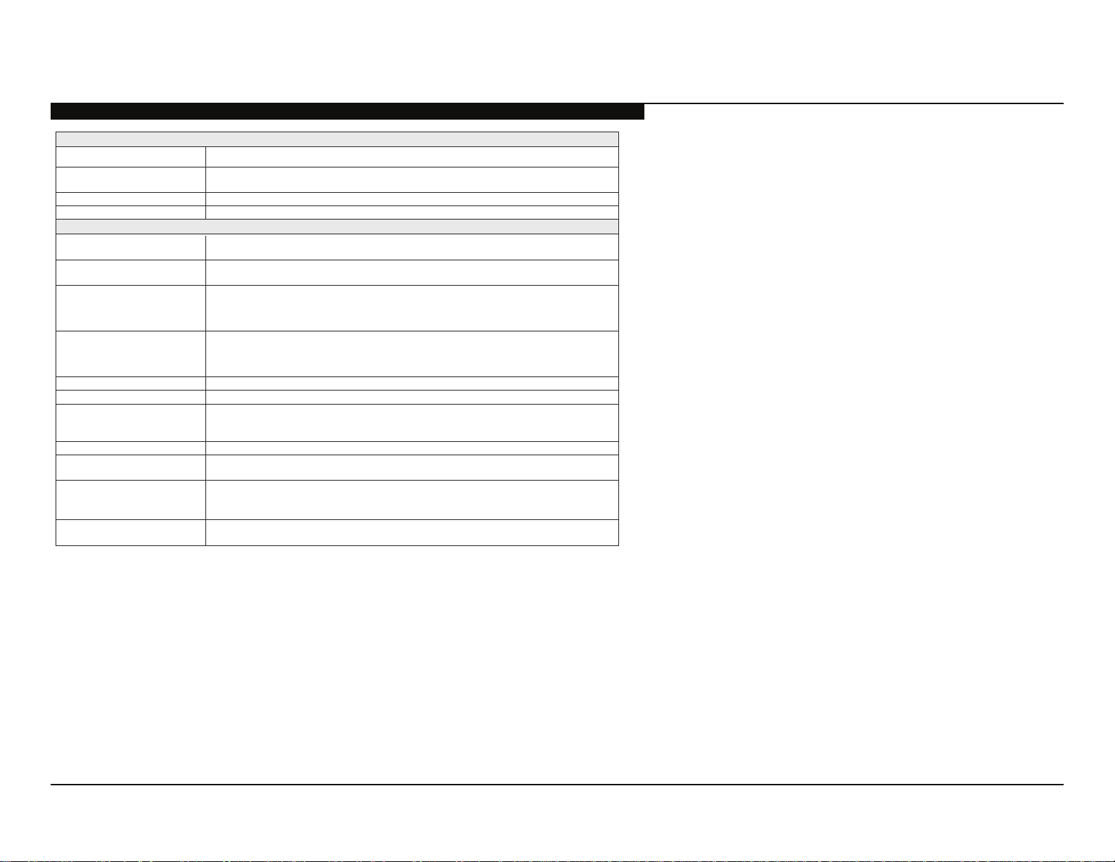
Sistema
Sistema de TV
Cobertura de canales VHF: 2-13, UHF: 14-69
Sistema del panel Panel LCD (pantalla de cristal líquido)
Salida de bocinas 10 W + 10 W
Tomas de entrada/salida
CABLE/ANTENNA
(Cable/Antena)
VIDEO IN 1/2/3
(Entrada de video 1/2/3)
COMPONENT IN 1/2
(Entrada de componente 1/2)
HDMI IN 1/2/3/4
(Entrada HDMI 1/2/3/4)
AURICULAR Minitoma estéreo
AUDIO OUT (Salida de audio) 500 mVrms (típico)
DIGITAL AUDIO OUT
(OPTICAL)
(Salida de audio digital óptica)
PC IN (Entrada de PC) Subminiatura D de 15 contactos, RGB anal
PC/HDMI 4 AUDIO IN
(Entrada de audio de PC/HDMI 4)
LAN Conector 10BASE-T/100BASE-TX
*1 Para conexiones LAN, utilice un cable 10BASE-T/100BASE-TX de categoría 7 (no se suministra).
• La disponibilidad de los accesorios opcionales dependerá de las existencias.
• El diseño y las especificaciones están sujetos a cambios sin previo aviso.
Digital: SBTVD
CATV (Análogo): 1-125
Terminal externo de 75 ohmios para entrada de señal de radiofrecuencia
VIDEO / AUDIO
YP
BPR (video componente)
Formato de señal:
AUDIO
HDMI: Video:
HDMI:
AUDIO (HDMI IN 4)
Señal de audio óptica digital PCM/Dolby Digital
Minitoma estéreo
(La velocidad de la conexión podría variar en función del entorno de red. No se garantizan la tasa de
comunicación ni la calidad de comunicación 10BASE-T/100BASE-TX para este TV.)*
(DLNA está disponible únicamente
(para los modelos series EX406/EX405/EX306/EX305)
480i, 480p, 576i, 576p, 720p, 1080i, 1080p
480i, 480p, 576i, 576p, 720p, 1080i, 1080p, 1080/24p
Audio: PCM lineal de dos canales 32; 44,1 y 48 kHz, 16, 20 y 24 bits, Dolby Digital
ó
gico
.elbitapmoc otamrof le arap launaM-i le etlusnoCANLD/BSU
1
KDL-32EX305/32EX306/32EX405/40EX405/40EX406/46EX405 1
Page 7
SPECIFICATIONS
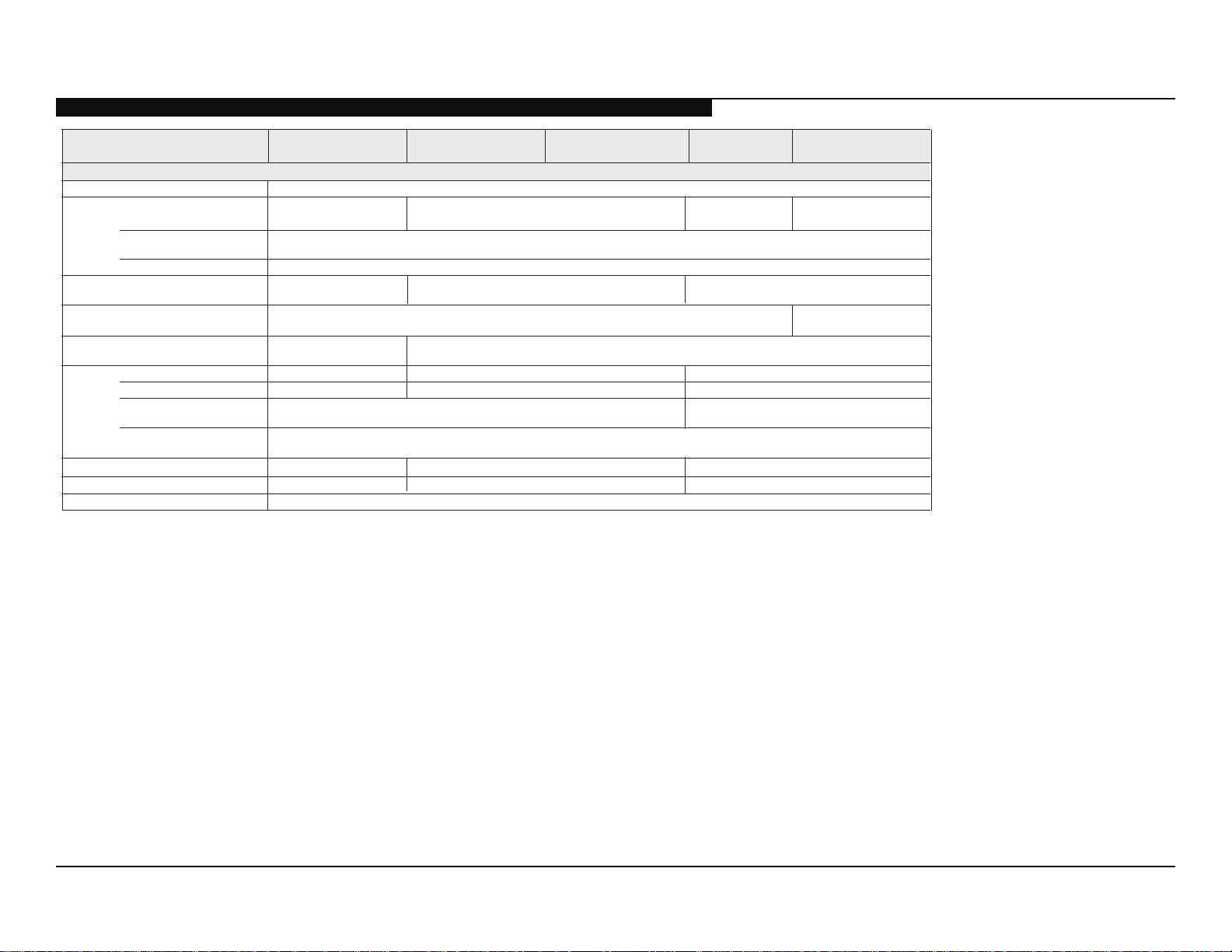
Nombre del modelo KDL-
Alimentación y otras especificaciones
Requisitos de alimentación 110 V -240 V ca, 50/60 Hz
Consumo energético
en uso
2
en DAM*
Tamaño de pantalla
(medido diagonalmente)
Bocina
Gama completa con parlantes (2)
Dimensiones con soporte
patrón de orificios de montaje mural
tamaño de tornillos de montaje mural
*2 El modo de adquisición de descarga (DAM) se utiliza para actualizaciones de software.
• La disponibilidad de los accesorios opcionales dependerá de las existencias.
• El diseño y las especificaciones están sujetos a cambios sin previo aviso.
(cm)
(pulgadas)
(mm)
052 × 536 × 299)mm(
(mm)
(mm)
46EX405 40EX406 40EX405
(Se puede oír un ruido durante la descarga pero es normal.)
116,8
46
541 × 54
1.127 × 711 × 294
1.127 × 674 × 102
M6 (longitud: consulte el diagrama de la página 15.)
ed selbaCselanoicpo soiroseccA conexión / Kit de correa de soporte / Soporte de montaje mural
W 51
300 × 300
32EX405
W 551W 971
W 2,0 ed soneMarepse ne
101,6
40
)lacitrev( saeníl 080.1 × )latnoziroh( sotnup 029.1 rotinom led nóiculoseR
45 × 130
001 × 895 × 299)mm(etropos nis
9,5120,4)gk( etropos nocoseP
9,311,81)gk( etropos nis
80,0
31,5 (32 clase)
200 × 200
32EX306
32EX305
W 311W 411
1.366 puntos (horizontal) ×
768 líneas (vertical)
022 × 235 × 008
79 × 794 × 008
0,11
5,9
Verificación de los accesorios
Cable de alimentación de ca (1)
(para modelos KDL-46EX405)
Soporte de sobremesa (1)*
Cómo fijar tornillos para el soporte de sobremesa (M5 × 16) (4)
Cómo montar tornillos para el soporte de sobremesa (M4 × 10) (3)
Control remoto (1)*
2
Pilas de tamaño AAA (2)
*1Los modelos de 32” (80,0 cm) y 40” (101, 6 cm) requieren montaje.
Consulte el otro folleto para ensamblar el soporte.
2
Consulte el nombre del modelo impreso en el control remoto.
*
KDL-32EX305/32EX306/32EX405/40EX405/40EX406/46EX405 2
1
Page 8
WARNINGS AND CAUTIONS
CAUTION
These servicing instructions are for use by qualifi ed service personnel only. To reduce the risk of electric shock, do not perform any servicing
other than that contained in the operating instructions unless you are qualifi ed to do so.
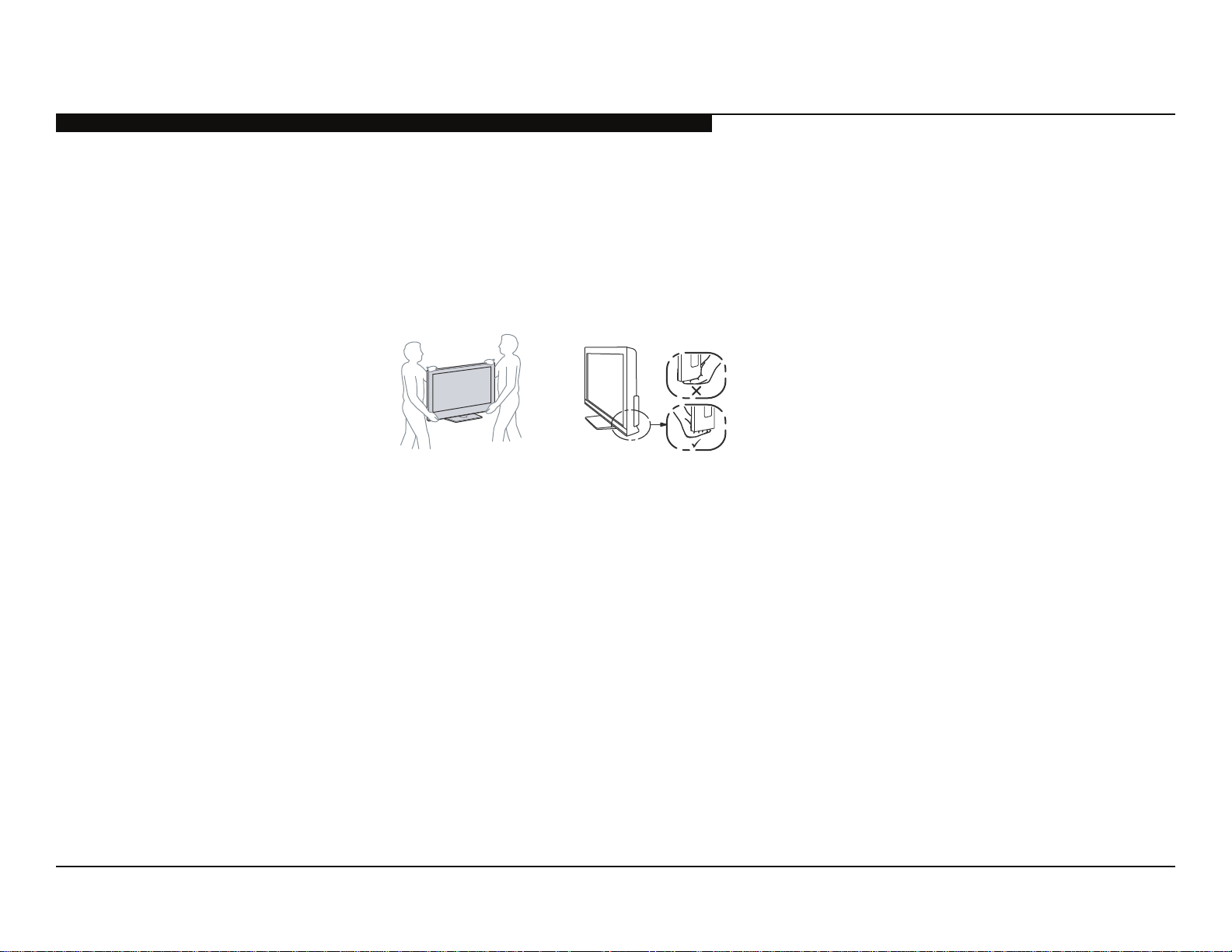
CARRYING THE TV
• Carry the TV with the adequate number of people; larger size TVs require two or more people.
• Correct hand placement while carrying the TV is very important for safety and to avoid
damage.
WARNING!!
An isolation transformer should be used during any service to avoid possible shock hazard, because of live chassis. The chassis of this
receiver is directly connected to the AC power line.
! SAFETY-RELATED COMPONENT WARNING!!
Components identifi ed by shading and ! mark on the exploded views are critical for safe operation.
Replace all components with Sony parts whose part numbers appear as shown in this manual or in supplements published by Sony. It is
essential that all critical parts be replaced only with the part number specifi ed in this manual to prevent electric shock, fi re, or other hazard.
Circuit adjustments that are critical for safe operation are identifi ed in this manual.
Follow these procedures whenever critical components are replaced or improper operation is suspected.
NOTE: Do not modify the original design without obtaining written permission from the manufacturer or you will void the original parts and
labor guarantee.
KDL-32EX305/32EX306/32EX405/40EX405/40EX406/46EX405 3
Page 9

SAFETY-RELATED WARNING
USE CAUTION WHEN HANDLING THE LCD PANEL
When repairing the LCD panel, be sure you are grounded by using a wrist band.
When installing the LCD panel on a wall, the LCD panel must be secured using the 4 mounting holes on the rear cover.
1) Do not press on the panel or frame edge to avoid the risk of electric shock.
2) Do not scratch or press on the panel with any sharp objects.
3) Do not leave the module in high temperatures or in areas of high humidity for an extended period of time.
4) Do not expose the LCD panel to direct sunlight.
5) Avoid contact with water. It may cause a short circuit within the module.
6) Disconnect the AC power when replacing the backlight (CCFL) or inverter circuit.
(High voltage occurs at the inverter circuit at 650Vrms.)
7) Always clean the LCD panel with a soft cloth material.
8) Use care when handling the wires or connectors of the inverter circuit. Damaging the wires may cause a short.
9) Protect the panel from ESD to avoid damaging the electronic circuit (C-MOS).
KDL-32EX305/32EX306/32EX405/40EX405/40EX406/46EX405 4
Page 10

SAFETY CHECK-OUT
After correcting the original service problem, perform the following safety checks before releasing the set to the customer:
1. Check the area of your repair for unsoldered or poorly soldered connections.
Check the entire board surface for solder splashes and bridges.
2. Check the interboard wiring to ensure that no wires are “pinched” or touching
high-wattage resistors.
3. Check that all control knobs, shields, covers, ground straps, and mounting
hardware have been replaced. Be absolutely certain that you have replaced
all the insulators.
4. Look for unauthorized replacement parts, particularly transistors, that were
installed during a previous repair. Point them out to the customer and
recommend their replacement.
0.15 μF
To Exposed Metal
Parts on Set
AC
Voltmeter
(0.75V)
5. Look for parts which, though functioning, show obvious signs of deterioration.
Point them out to the customer and recommend their replacement.
6. Check the line cords for cracks and abrasion. Recommend the replacement
of any such line cord to the customer.
7. Check the antenna terminals, metal trim, “metallized” knobs, screws, and
all other exposed metal parts for AC leakage. Check leakage as described
below.
Figure A. Using an AC voltmeter to check AC leakage.
Earth Ground
KDL-32EX305/32EX306/32EX405/40EX405/40EX406/46EX405 5
Page 11
LEAKAGE TEST
The AC leakage from any exposed metal part to earth ground and from all
exposed metal parts to any exposed metal part having a return to chassis, must
not exceed 0.5 mA(500 microamperes). Leakage current can be measured by
any one of three methods.
1. A commercial leakage tester, such as the Simpson 229 or RCA WT-540A.
Follow the manufacturers’ instructions to use these instructions.
2. A battery-operated AC milliampmeter. The Data Precision 245 digital
multimeter is suitable for this job.
3. Measuring the voltage drop across a resistor by means of a VOM or batteryoperated AC voltmeter. The “limit” indication is 0.75 V, so analog meters
must have an accurate low voltage scale.
SAFETY CHECK-OUT
Trouble Light
AC Outlet Box
Ohmmeter
The Simpson’s 250 and Sanwa SH-63TRD are examples of passive VOMs
that are suitable. Nearly all battery-operated digital multimeters that have a
2 VAC range are suitable (see Figure A).
Cold-water Pipe
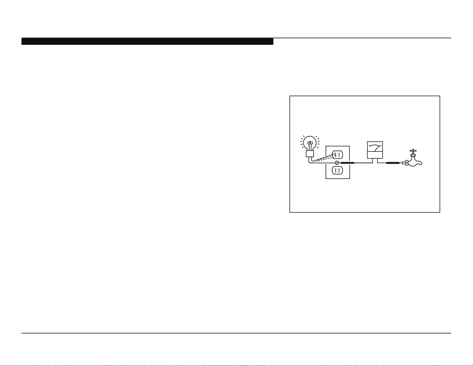
HOW TO FIND A GOOD EARTH GROUND
A cold-water pipe is a guaranteed earth ground; the cover-plate retaining screw
on most AC outlet boxes is also at earth ground.
If the retaining screw is to be used as your earth ground, verify that it is at
ground by measuring the resistance between it and a cold-water pipe with an
ohmmeter. The reading should be zero ohms.
If a cold-water pipe is not accessible, connect a 60-to 100-watt trouble-light (not
a neon lamp) between the hot side of the receptacle and the retaining screw.
Try both slots, if necessary, to locate the hot side on the line; the lamp should
light at normal brilliance if the screw is at ground potential (see Figure B).
KDL-32EX305/32EX306/32EX405/40EX405/40EX406/46EX405 6
Figure B. Checking for earth ground.
Page 12

SELF DIAGNOSIS FUNCTIONS
SELF DIAGNOSIS FUNCTION
The units in this manual contain a self-diagnostic function. If an error occurs, the STANDBY LED will automatically begin to fl ash. The number
of times the LED fl ashes translates to a probable source of the problem. A defi nition of the STANDBY LED fl ash indicators is listed in the
instruction manual for the user’s knowledge and reference. If an error symptom cannot be reproduced, the remote commander can be used to
review the failure occurrence data stored in memory to reveal past problems and how often these problems occur.
DIAGNOSTIC TEST INDICATORS
When an error occurs, the STANDBY LED will fl ash a set number of times to indicate the possible cause of the problem. If there is more than
one error, the LED will identify the fi rst of the problem areas.
Result for all of the following diagnostic items are displayed on screen.
If the screen displays a “0”, no error has occurred .
Self Diagnosis
Supported model
Diagnostic Item
Diagnostic Item
RGB_SEN RGB Sensor ACK Error NA NA
MAIN_POWER Main Power Over Voltage Protection 2
DC_ALERT DC Alert
DTT-WDT DTT Error
AUD_PROT Audio Error Detection
BALANCER Panel Balancer Error 4
TCON ERR TCON Error
HFR ERR HFR Error
P_ID_ERR Panel ID NVM Error
BACKLITE Backlight Error 6
TEMP_ERR Temperature Error 7 BAL Board
FAN_ERR Fan Error (Not Detected; Display Only) NA NA
Description
Number of times Standby
LED blinks
3
5
Possible Location
G2LE (Power) Board (KDL-32EX305, KDL-32EX306 and KDL-32EX405 ONLY)
G2HE (Power) Board (KDL-40EX405 and KDL-40EX406 ONLY)
GD2 (Power) Board (KDL-46EX405 ONLY)
BAL Board
BAL Board
G2LE (Power) Board (KDL-32EX305, KDL-32EX306 and KDL-32EX405 ONLY)
G2HE (Power) Board (KDL-40EX405 and KDL-40EX406 ONLY)
GD2 (Power) Board (KDL-46EX405 ONLY)
BAL Board
LCD Panel
TCON Control MT Board
BAL Board
BAL Board
KDL-32EX305/32EX306/32EX405/40EX405/40EX406/46EX405 7
Page 13

STANDBY LED FLASH COUNT
Ambient Sensor/
(IR) Infrared Receiver
Picture Off /
Timer LED
Standby LED Power LED
SELF DIAGNOSIS FUNCTIONS
2 times
5 times
LED ON 0.3 sec.
LED OFF 0.3 sec.
LED OFF
3 sec.
KDL-32EX305/32EX306/32EX405/40EX405/40EX406/46EX405 8
Page 14

VIEWING THE SELF CHECK DIAGNOSTIC LIST
For errors with symptoms such as “power sometimes shuts off” or “screen sometimes goes out” that cannot be confi rmed, it is possible to
bring up past occurrences of a failure for confi rmation on the Self Check diagnostic screen:
1. TV must be in standby mode. (Power off).
2. Press the following buttons on the Remote Commander within a second of each other:
SELF DIAGNOSIS FUNCTIONS
DISPLAY
Channel 5 Volume -
* NOTE: This differs from accessing Service Adjustments Mode (Volume +)
SELF CHECK
000 RGB_SEN
002 MAIN_POWE
003 DC_ALERT1
003 AUD_PROT
003 DTT_WDT
004 BALANCER
005 HFR_ERR
005 TCON_ERR
005 P_ID_ERR
006 BACKLITE
007 TEMP_ERR
007 FAN_ERR
010 RESERVED
011 RESERVED
12345-00333-0678912345-00333-06789--
-------------- -------------- -------------- 00
0501210811 0412311234 0311111825 00
-------------- -------------- -------------- 00
-------------- -------------- -------------- 00
-------------- -------------- -------------- 00
-------------- -------------- -------------- 00
-------------- -------------- -------------- 00
-------------- -------------- -------------- 00
-------------- -------------- -------------- 00
-------------- -------------- -------------- 00
-------------- -------------- -------------- 00
-------------- -------------- -------------- 00
-------------- -------------- -------------- 00
-------------- -------------- -------------- 00
POWER
.
Error count (00-99)
Error count (00-99)
Error history (Last failure time beforehand)
Error history (Last failure time beforehand)
Error history (Failure time before last)
Error history (Failure time before last)
Error history (The last failure time)
Error history (The last failure time)
Item name
Item name
STBY LED flash time
STBY LED flash time
Panel operation time by hour (MAX:65535)
Panel operation time by hour (MAX:65535)
Boot count (MAX:65535)
Boot count (MAX:65535)
Total operation time by hour (MAX:65535)
Total operation time by hour (MAX:65535)
KDL-32EX305/32EX306/32EX405/40EX405/40EX406/46EX405 9
Page 15

SELF DIAGNOSIS FUNCTIONS
CLEARING THE SELF CHECK DIAGNOSTIC LIST
Since the diagnostic results displayed on the screen are not automatically cleared, always check the self-diagnostic screen after you have
completed the repairs to be sure you have cleared the result display to “0”.
1. Error history and Error count :Press the Channel 8 Channel 0 .
2. Panel operation time :Press the Channel
7
Channel 0 .
EXITING THE SELF CHECK DIAGNOSTIC SCREEN
1. To exit the Self Diagnostic screen, turn off the power to the TV by pressing the POWER button on the remote or the POWER button on
the TV.
KDL-32EX305/32EX306/32EX405/40EX405/40EX406/46EX405 10
Page 16

SEC 1. DISASSEMBLY/PART NUMBER INFORMATION
1-1. TABLE-TOP STAND ASSEMBLY REMOVAL
A
Remove 4 screws from Table-Top Stand Assemblyy
B
Lift TV set up to detach from Table-Top Stand Assembly
Components not identifi ed by a part number or
description are not stocked because they are seldom
required for routine service.
NOTE: The components identifi ed by shading
and ! mark are critical for safety. Replace only
with part number specifi ed.
6
A
B
7
The component parts of an assembly are indicated by the
reference numbers in the far right column of the parts list
and within the dotted lines of the diagram.
NOTE: The components identifi ed by a red outline and a mark contain
confi dential information. Specifi c instructions must be adhered to whenever
these components are repaired and/or replaced.
See Appendix A: Encryption Key Components in the back of this manual.
4
5
3
Items marked with an asterisk are not stocked since
*
they are seldom required for routine service. Expect
some delay when ordering these components.
1
2
C
Gently place the TV set face down onto a soft cloth
C
Soft Cloth
REF. NO. PART NO. DESCRIPTION [ASSEMBLY INCLUDES] REF. NO. PART NO. DESCRIPTION [ASSEMBLY INCLUDES]
1 X-2514-986-1 BASE (M3B) ASSEMBLY
(KDL-32EX305/32EX306/32EX405 ONLY)
1 X-2514-987-1 BASE (ML3B) ASSEMBLY
(KDL-40EX405/40EX406 ONLY)
1 X-2514-988-1 BASE (L3B) ASSEMBLY
(KDL-46EX405 ONLY)
2 4-158-391-01 COVER, STAND (ML3B)
(KDL-40EX405/40EX406 ONLY)
3 4-158-374-01 BASE, STAND (ML3B)
(KDL-40EX405/40EX406 ONLY)
4 4-174-813-01 COVER, NECK (M3B)
(KDL-32EX305/32EX306/32EX405 ONLY)
4 4-158-401-01 COVER, NECK (ML3B)
(KDL-40EX405/40EX406/46EX405 ONLY)
5 4-174-808-01 NECK (M3B)
(KDL-32EX305/32EX306/32EX405 ONLY)
* 5 4-158-355-01 NECK (ML3B)
(KDL-40EX405/40EX406/46EX405 ONLY)
6 4-159-298-01 SCREW, +PSW M4X10
(SCREWS TO ATTACH NECK TO BASE ASSEMBLY)
7 2-580-608-01 SCREW, +PSW M5X16
(SCREWS TO ATTACH TABLE-TOP STAND TO LCD TV)
For product protection and safety reasons, Sony strongly recommends
that you use the screws provided with the TV
CAUTION: These screws cannot be used to secure the TV to
the Wall Mount Brackets
2-580-608-01 SCREW, +PSW M5X16
KDL-32EX305/32EX306/32EX405/40EX405/40EX406/46EX405 11
Page 17

DISASSEMBLY/PART NUMBER INFORMATION
1-2. REAR COVER AND VESA BRACKET REMOVAL
A
Remove screws from Rear Cover
10 from KDL-32EX305/32EX306/32EX405 ONLY
8 from KDL-40EX405/40EX406 ONLY
11 from KDL-46EX405 ONLY
B
Remove 2 screws from Rear Cover Top-Center
C
Remove 2 screws from Rear Cover Bottom-Center
(KDL-40EX405/40EX406/46EX405 ONLY)
D
Remove 1 screw from Terminal position
E
Remove 1 screw from Side Jack position
F
Lift up Rear Cover from bottom to remove from Bezel
Assembly
G
Disconnect Power Cord from Power (G2LE/G2HE)
Board and detach from Under Cover
(ALL EXCEPT KDL-46EX405)
Disconnect Power Cord from AC Inlet and detach from
Under Cover (KDL-46EX405 ONLY)
H
Remove 1 screw from Under Cover to detach from
Bottom Frame
I
Slide out Vesa Brackets to remove from Rear Cover
NOTE: The components identifi ed by shading
and ! mark are critical for safety. Replace only
with part number specifi ed.
NOTE: The components identifi ed by a red outline and a mark contain
confi dential information. Specifi c instructions must be adhered to whenever
these components are repaired and/or replaced.
See Appendix A: Encryption Key Components in the back of this manual.
54
53
52
NOTE: The Vesa Brackets are not included with
the Rear Cover and must be reattached to the
replacement Rear Cover
A
B
KDL-32EX305,
KDL-32EX306 and
KDL-32EX405 Only
KDL-40EX405,
KDL-40EX406 and
KDL-46EX405 Only
C
KDL-32EX305,
KDL-32EX306 and
KDL-32EX405 Only
KDL-40EX405,
KDL-40EX406 and
KDL-46EX405 Only
I
REF. NO. PART NO. DESCRIPTION [ASSEMBLY INCLUDES] REF. NO. PART NO. DESCRIPTION [ASSEMBLY INCLUDES]
H
G
F
D
E
51 4-172-264-21 REAR COVER (32)
(KDL-32EX305/32EX306/32EX405 ONLY)
51 4-167-455-11 REAR COVER (40)
(KDL-40EX405/40EX406 ONLY)
51 4-166-856-21 REAR COVER (46)
(KDL-46EX405 ONLY)
52 3-297-324-02 COVER, ECS
53 4-166-138-01 COVER, UNDER (32)
(KDL-32EX305/32EX306/32EX405 ONLY)
53 4-166-136-01 COVER, UNDER (37)
(KDL-40EX405/40EX406 ONLY)
53 4-166-136-11 COVER, UNDER (37)
(KDL-46EX405 ONLY)
51
54 4-167-326-01 BRACKET, VESA (S)
(ALL EXCEPT KDL-46EX405)
54 4-168-272-01 BRACKET, VESA (S)
(KDL-46EX405 ONLY)
2-580-640-01 SCREW, +BVTP 4X16 TYPE2 IT-3
2-580-595-01 SCREW, +PSW M3X12
(KDL-32EX305/32EX306/32EX405 ONLY)
7-685-648-79 SCREW +BVTP 3X12 TYPE2 IT-3
4-159-298-01 SCREW, +PSW M4X10
KDL-32EX305/32EX306/32EX405/40EX405/40EX406/46EX405 12
Page 18

DISASSEMBLY/PART NUMBER INFORMATION
1-3. AC INLET, SPEAKER BRACKETS AND LOUDSPEAKERS REMOVAL
A
Remove 1 screw from AC Bracket to detach from Bottom Frame (KDL-46EX405 ONLY)
B
Remove 1 screw from AC Inlet to detach from AC Bracket (KDL-46EX405 ONLY)
C
Remove 1 screw from Speaker Bracket Left to detach from Bezel Assembly
(ALL EXCEPT KDL-46EX405)
Slide-out Speaker Bracket Left to detach from Bezel Assembly (KDL-46EX405 ONLY)
D
Remove 2 screws from Loudspeaker to remove from Speaker Bracket Left
E
Remove 1 screw from Speaker Bracket Right to detach from Bezel Assembly
(ALL EXCEPT KDL-46EX405)
Slide-out Speaker Bracket Right to detach from Bezel Assembly (KDL-46EX405 ONLY)
F
Remove 2 screws from Loudspeaker to remove from Speaker Bracket Right
KDL-32EX305, KDL-32EX306,
KDL-32EX405, KDL-40EX405
and KDL-40EX406 Only
KDL-46EX405 Only
NOTE: The components identifi ed by shading
and ! mark are critical for safety. Replace only
with part number specifi ed.
101
104
AC Inlet
Bracket
NOTE: The components identifi ed by a red outline and a mark contain
confi dential information. Specifi c instructions must be adhered to whenever
these components are repaired and/or replaced.
See Appendix A: Encryption Key Components in the back of this manual.
103
101
F
E
KDL-32EX305, KDL-32EX306,
KDL-32EX405, KDL-40EX405
A
B
C
and KDL-40EX406 Only
KDL-46EX405 Only
D
REF. NO. PART NO. DESCRIPTION [ASSEMBLY INCLUDES] REF. NO. PART NO. DESCRIPTION [ASSEMBLY INCLUDES]
101 1-858-364-22 LOUDSPEAKER
(ALL EXCEPT KDL-46EX405)
101 1-858-371-11 LOUDSPEAKER (4.5X20CM)
(KDL-46EX405 ONLY)
102 4-166-133-01 BRACKET, SP (32L)
(KDL-32EX305/32EX306/32EX405 ONLY)
102 4-166-131-01 BRACKET, SP (40L)
(KDL-40EX405/40EX406 ONLY)
102 X-2547-454-1 SP BRACKET (46L) ASSEMBLY
(KDL-46EX405 ONLY)
102
! 103 1-842-104-31 AC INLET
(KDL-46EX405 ONLY)
104 4-166-134-01 BRACKET, SP (32R)
(KDL-32EX305/32EX306/32EX405 ONLY)
104 4-166-132-01 BRACKET, SP (40R)
(KDL-40EX405/40EX406 ONLY)
104 X-2547-455-1 SP BRACKET (46R) ASSEMBLY
(KDL-46EX405 ONLY)
2-580-640-01 SCREW, +BVTP 4X16 TYPE2 IT-3
7-685-648-79 SCREW +BVTP 3X12 TYPE2 IT-3
2-580-629-01 SCREW, +BVST 3X8
(KDL-46EX405 ONLY)
4-167-964-01 SCREW, +PWTP2 4X16
(KDL-46EX405 ONLY)
KDL-32EX305/32EX306/32EX405/40EX405/40EX406/46EX405 13
Page 19

DISASSEMBLY/PART NUMBER INFORMATION
1-4. G2LE/G2HE/GD2 (POWER) BOARD, BAL BOARD, LCD PANEL, AND HLR BOARD REMOVAL
A
Slide Side Jack Bracket to right-side of BAL Board to detach from position
B
Remove 4 screws from BAL Board
C
Disconnect 5 connectors from BAL Board
D
Remove 1 PWB Holder to detach BAL Board from LCD Panel
E
Remove 2 screws from Bottom Frame to detach from Bezel Assembly
(KDL-40EX405/40EX406/46EX405 ONLY)
F
Remove 2 screws from Bottom Frame to detach from LCD Panel
G
Remove 4 screws from G2LE/G2HE/GD2 (Power) Board
H
Disconnect 4 connectors from G2LE/G2HE (Power) Board
Disconnect 6 connectors from GD2 (Power) Board
I
Lift up Switch Unit and disconnect 1 connector to remove from Bezel
J
Press down on Panel Support
and slide-out to remove from
Bezel Assembly
K
Carefully Lift up Panel to
remove from Bezel Assembly
L
Disconnect 1 connector from
HLR Board and release clips,
then lift up to detach from
position
NOTE: The Mini Card Spacers
and PWB Holder are not
included with the Boards
and must be replaced when
replacing the Boards.
I
Mini Card
Spacer
H
G
J
K
L
F
E
C
D
B
A
NOTE: The components identifi ed by shading
and ! mark are critical for safety. Replace only
with part number specifi ed.
158
157
156
REF. NO. PART NO. DESCRIPTION [ASSEMBLY INCLUDES] REF. NO. PART NO. DESCRIPTION [ASSEMBLY INCLUDES]
151 NA SUPPORT, PANEL
FOR ALL SUPPORT PANEL PART NUMBER INFORMATION
REFER TO THE LCD PANELS SERVICE MANUAL
152 X-2547-553-1 BEZEL ASSEMBLY (CY32 LS)
(KDL-32EX305 ONLY)
152 X-2547-647-1 BEZEL ASSEMBLY (CY32D GM)
(KDL-32EX306 ONLY)
152 X-2547-547-1 BEZEL ASSEMBLY (CY32 DS)
(KDL-32EX405 ONLY)
152 X-2547-548-1 BEZEL ASSEMBLY (CY40 DS)
(KDL-40EX405 ONLY)
152 X-2547-648-1 BEZEL ASSEMBLY (CY40D GM)
(KDL-40EX406 ONLY)
152 X-2547-555-2 BEZEL ASSEMBLY (CY46 DS)
(KDL-46EX405 ONLY)
153 A-1753-637-A HLR BOARD, MOUNTED
154 NA LCD PANEL
FOR ALL LCD PANEL PART NUMBER INFORMATION
REFER TO THE LCD PANELS SERVICE MANUAL
155 4-175-711-01 BRACKET, SIDE JACK
NOTE: The components identifi ed by a red outline and a mark contain
confi dential information. Specifi c instructions must be adhered to whenever
these components are repaired and/or replaced.
See Appendix A: Encryption Key Components in the back of this manual.
151
152
153
154
155
156 A-1761-435-A BAL BOARD, COMPLETE
(KDL-32EX305/32EX306 ONLY)
156 A-1761-434-A BAL BOARD, COMPLETE
(KDL-32EX405/40EX405/-40EX406/46EX405 ONLY)
NOTE: For BAL Board replacement, please refer to section
2-2. Adjustments After Replacing the BAL Board or LCD Panel
NOTE: Final software is not installed on this BAL Board. Install the update after
replacing this board using the instructions provided with the software.
157 1-474-200-11 G2LE (POWER) BOARD, COMPLETE
(KDL-32EX305/32EX306/32EX405 ONLY)
157 1-474-202-21 G2HE (POWER) BOARD, COMPLETE
(KDL-40EX405/40EX406 ONLY)
157 1-474-205-11 GD2 (POWER) BOARD, COMPLETE
(KDL-46EX405 ONLY)
158 1-487-725-11 SWITCH UNIT
2-580-640-01 SCREW, +BVTP 4X16 TYPE2 IT-3
2-580-592-01 SCREW, +PSW M3X8
4-159-298-01 SCREW, +PSW M4X10
KDL-32EX305/32EX306/32EX405/40EX405/40EX406/46EX405 14
Page 20

DISASSEMBLY/PART NUMBER INFORMATION
1-5. CLEANING THE LCD PANEL
CAUTION: When cleaning the TV, be sure to unplug the power cord to avoid any chance of electric shock.
Clean the cabinet of the TV with a dry soft cloth.
ipe the LCD screen gently with a soft cloth.
W
Stubborn stains may be removed with a cloth slightly moistened with a solution of mild soap and warm water.
If using a chemically pretreated cloth, please follow the instruction provided on the package.
Never use strong solvents such as a thinner, alcohol or benzine for cleaning.
Periodic vacuuming of the ventilation openings is recommended to ensure to proper ventilation.
1-6. SCREW LEGEND
KDL-32EX305, KDL-32EX306 and KDL-32EX405
P/N DISCRIPTION REMARKS TOTAL
2-580-640-01 SCREW, +BVTP 4X16 TYPE2 IT-3 RC(10), SPKR BRKT-L(1), SPKR BRKT-R(1) 12
Ṳ
2-580-595-01 SCREW, +PSW M3X12 RC TOP-CENTER(2) 2
ṳ
7-685-648-79 SCREW, +BVTP 3X12 TYPE2 IT-3 RC to SIDE JACK(1), RC to TRMNL AREA(1), SPKR-L(2), SPKR-R(2) 6
Ṷ
2-580-608-01 SCREW, +PSW M5X16 TABLE-TOP STAND(4) 4
ṷ
2-580-592-01 SCREW, +PSW M3X8 G2LE(4), BAL(4) 8
Ṽ
4-159-298-01 SCREW, +PSW M4X10 UNDER COVER(1), BTM FRM(2), NECK to BASE(3) 6
Ź
2-580-629-01 SCREW, +BVST 3X8 NOT IN THIS MODEL 0
Ṿ
4-167-964-01 SCREW, +PWTP2 4X16 NOT IN THIS MODEL 0
ṿ
NOTE: The components identifi ed by shading
and ! mark are critical for safety. Replace only
with part number specifi ed.
NOTE: The components identifi ed by a red outline and a mark contain
confi dential information. Specifi c instructions must be adhered to whenever
these components are repaired and/or replaced.
See Appendix A: Encryption Key Components in the back of this manual.
KDL-40EX405 and KDL-40EX406
P/N DISCRIPTION REMARKS TOTAL
2-580-640-01 SCREW, +BVTP 4X16 TYPE2 IT-3 RC(8), SPKR BRKT-L(1), SPKR BRKT-R(1), BTM FRM to BEZ ASSY(2) 12
Ṳ
2-580-595-01 SCREW, +PSW M3X12 NOT IN THIS MODEL 0
ṳ
7-685-648-79 SCREW, +BVTP 3X12 TYPE2 IT-3 RC to SIDE JACK(1), RC to TRMNL AREA(1), SPKR-L(2), SPKR-R(2) 6
Ṷ
2-580-608-01 SCREW, +PSW M5X16 TABLE-TOP STAND(4) 4
ṷ
2-580-592-01 SCREW, +PSW M3X8 G2HE(4), BAL(4) 8
Ṽ
4-159-298-01 SCREW, +PSW M4X10 RC TOP-CENTER(2), RC BTM-CENTER(2), UNDER COVER(1), BTM FRM(2), NECK to BASE(3) 10
Ź
2-580-629-01 SCREW, +BVST 3X8 NOT IN THIS MODEL 0
Ṿ
4-167-964-01 SCREW, +PWTP2 4X16 NOT IN THIS MODEL 0
ṿ
KDL-46EX405
P/N DESCRIPTION REMARKS TOTAL
2-580-640-01 SCREW, +BVTP 4X16 TYPE2 IT-3 RC(11), BTM FRM to BEZ ASSY(2) 13
Ṳ
2-580-595-01 SCREW, +PSW M3X12 NOT IN THIS MODEL 0
ṳ
7-685-648-79 SCREW +BVTP 3X12 TYPE2 IT-3 RC to SIDE JACK(1), RC to TRMNL AREA(1) 2
Ṷ
2-580-608-01 SCREW, +PSW M5X16 TABLE-TOP STAND(4) 4
ṷ
2-580-592-01 SCREW, +PSW M3X8 GD2(4), BAL(4) 8
Ṽ
4-159-298-01 SCREW, +PSW M4X10 RC TOP-CENTER(2), RC BTM-CENTER(2), UNDER COVER(1), BTM FRM(2), NECK to BASE(3) 10
Ź
2-580-629-01 SCREW, +BVST 3X8 AC BRKT to BTM FRAME(1), AC INLET to AC BRKT(1) 2
Ṿ
4-167-964-01 SCREW, +PWTP2 4X16 SPKR-L to SPKR ASSY-L(2), SPKR-R to SPKR ASSY-R(2) 4
ṿ
KDL-32EX305/32EX306/32EX405/40EX405/40EX406/46EX405 15
Page 21

DISASSEMBLY/PART NUMBER INFORMATION
1-7. CONNECTORS
1-7-1. ALL EXCEPT KDL-46EX405 1-7-2. KDL-46EX405 ONLY
INV
SWITCH UNIT
204
CN6402
CN6401
G2LE/G2HE
CN2601 (KDL-32EX305/32EX306 ONLY)
CN2600 (KDL-32EX405/40EX405/40EX406 ONLY)
TCON
203
CNxxxx
202
CN4300
CN3800
CN2561
CN2602
BAL
201
NOTE: The components identifi ed by shading
and ! mark are critical for safety. Replace only
with part number specifi ed.
254
CN6705CN6704
205
INV
CN6702
CN6150
GD2
SWITCH UNIT
252
NOTE: The components identifi ed by a red outline and a mark contain
confi dential information. Specifi c instructions must be adhered to whenever
these components are repaired and/or replaced.
See Appendix A: Encryption Key Components in the back of this manual.
TCON
253
CN2600
CN4300
CN3800
CN2561
CN2602
BAL
251
SP SP
HLR
REF. NO. PART NO. DESCRIPTION [ASSEMBLY INCLUDES] REF. NO. PART NO. DESCRIPTION [ASSEMBLY INCLUDES]
201 1-910-101-28 HARNESS ASSEMBLY
(KDL-32EX305/32EX306/32EX405 ONLY)
201 1-910-101-30 HARNESS ASSEMBLY
(KDL-40EX405/40EX406 ONLY)
202 1-910-060-07 CONNECTOR ASSEMBLY 15P
(KDL-32EX305/32EX306/32EX405 ONLY)
202 1-910-060-15 CONNECTOR ASSEMBLY 15P
(KDL-40EX405/40EX406 ONLY)
203 1-837-515-12 (LVDS) FLEXIBLE FLAT CABLE 30P
(KDL-32EX305/KDL-32EX306 ONLY)
203 1-837-516-11 (LVDS) FLEXIBLE FLAT CABLE
(KDL-32EX405 ONLY)
* 203 1-837-520-11 (LVDS) FLEXIBLE FLAT CABLE
(KDL-40EX405/40EX406 ONLY)
* 204 1-910-060-08 CONNECTOR ASSEMBLY 14P
(KDL-32EX305/32EX306/32EX405 ONLY)
REF. NO. PART NO. DESCRIPTION [ASSEMBLY INCLUDES] REF. NO. PART NO. DESCRIPTION [ASSEMBLY INCLUDES]
251 1-910-101-31 HARNESS ASSY
252 1-910-060-19 CONNECTOR ASSY 15P
253 1-837-522-11 (LVDS) FLEXIBLE FLAT CABLE
254 1-837-317-21 CONNECTOR ASSY
255 1-910-060-20 CONNECTOR ASSY 5P
SPSP
HLR
* 204 1-910-060-16 CONNECTOR ASSEMBLY 14P
(KDL-40EX405/40EX406 ONLY)
KDL-32EX305/32EX306/32EX405/40EX405/40EX406/46EX405 16
Page 22

DISASSEMBLY/PART NUMBER INFORMATION
1-8. ACCESSORIES & PACKING
! 1-837-479-11 AC POWER-SUPPLY CORD
(ALL EXCEPT KDL-46EX405)
! 1-837-765-11 POWER-SUPPLY CORD SET
(KDL-46EX405 ONLY)
3-299-071-03 FLYER, SAFETY
4-180-188-31 MANUAL, INSTRUCTION
* 4-176-351-11 SUPPLEMENT(STAND INSTALLATION)
1-9. MISCELLANEOUS
7-632-452-24 TAPE (NO.303) 18MMX35M YEL
X-2348-140-3 SUPPORT BELT KIT
1-10. REMOTE COMMANDER
1-487-702-11 REMOTE COMMANDER (RM-YD047)
KDL-32EX305/32EX306/32EX405/40EX405/40EX406/46EX405 17
Page 23

SEC 2. SERVICE ADJUSTMENTS
2-1. ACCESSING SERVICE ADJUSTMENT MODE
1. TV must be in standby mode. (Power off).
2. Press the following buttons on the Remote Commander
within a second of each other:
DISPLAY
.
Channel 5 Volume +
POWER
DISPLAY
Onscreen cursor
and select button
POWER
.
DIGITAL S ERVICE
001 OP
000 VERS ---
<MAIN> <SUB>
DM1.301J00AA SM1.010W00AA
M2.105C SB1.000W00AA
DD1.016J00AA SD1.010W00AA
(DM1.3 01J00AA) RF01.05
WP00.521J00AA ID1C117081
ID1C117081 LTY320AB01
PID04020000
WF:2.0.0.99 <BEM>
WF:0B BM1.012W00LU
Camera FW BB1.000W00LU
Camera FW BD1.011J46LUX
---.---------
SAMPLE SERVICE MENU
5
VOLUME+
RM-YD047
KDL-32EX305/32EX306/32EX405/40EX405/40EX406/46EX405 18
Page 24

SERVICE ADJUSTMENTS
2-1-1. VIEWING THE SERVICE MENUS
Use the Remote Commander to view the Digital, Chassis and Sub
Service Menus and their options.
3. To display the Service Menu that contains the Category you
want to adjust, press
Commander.
DIGITAL S ERVICE
001 OP
000 VERS ---
<MAIN> <SUB>
DM1.301J00AA SM1.010W00AA
M2.105C SB1.000W00AA
DD1.016J00AA SD1.010W00AA
(DM1.3 01J00AA) RF01.05
WP00.521J00AA ID1C117081
ID1C117081 LTY320AB01
PID04020000
WF:2.0.0.99 <BEM>
WF:0B BM1.012W00LU
Camera FW BB1.000W00LU
Camera FW BD1.011J46LUX
JUMP
or
OPTIONS
---.---------
on the Remote
Within each Service Menu are Categories and data information.
Item name
Category name
Data
Item number
Category number
CHASSIS SERVICE
000 CXD2813R
000 H_DET_NOSIG_CNT 1
Sample Chassis Service Menu
Sample Digital Service Menu
JUMP
press
OPTIONS
or
CHASSIS
000 CXD2813R
000 H_DET_NOSIG_CNT 1
KDL-32EX305/32EX306/32EX405/40EX405/40EX406/46EX405 19
Page 25

SERVICE ADJUSTMENTS
2-1-2. USING THE REMOTE COMMANDER TO VIEW OR
CHANGE SERVICE DATA
Use the buttons on the Remote Commander to access the Service
Menu items and adjust the Data Values.
DISPLAY
4. To change the Category,
press 2 to move to the Next Category or
press 5 to go back to the Previous Category.
Note: Pressing 2 or 5 only changes the Categories within
the Service Menu displayed.
5. To change the adjustment item,
press 1 to move to the Next Item or
4
6. To change the Data Value,
press 3 to increase the Data Value or
6
7. P r e ss
8. To exit service mode, press
Channel 5 Volume +
to go back to the Previous Item.
to decrease the Data Value.
MUTING
then press 0 to Write the changes.
HOME
or turn the TV power off.
POWER
2-2. ADJUSTMENTS AFTER REPLACING THE BAL BOARD
OR LCD PANEL
The following procedures must be completed after replacing the BAL
Board or the LCD panel.
Update the TV to the latest software version
Select the Model
Select the Destination
Select the TV Color
Verify model and panel information are correct
Reconnect all cables
2-2-1. UPDATING THE SOFTWARE
After replacing the BAL Board or the LCD Panel, you must update the
software to the latest version.
Before you begin
Disconnect all cables (RF, External input, Ethernet, etc.) from
the TV
Instructions for updating the software are included with the software
package. After completing the software update, proceed to “Selecting the
Model”.
KDL-32EX305/32EX306/32EX405/40EX405/40EX406/46EX405 20
Page 26

2-2-2. SELECTING THE MODEL
䎧䏄䏗䏄䎃䎹䏄䏏䏘䏈 䎦䏒䏇䏈䎃䎱䏄䏐䏈
After replacing the BAL Board or LCD Panel, go into Service Mode to set
the Model data value.
1. TV must be in standby mode. (Power off).
2. Access Service Mode.
Press the following buttons on the Remote Commander
within a second of each other:
SERVICE ADJUSTMENTS
DIGITAL SERVICE
002 MODEL
000 SEG 01: 2a-3
DISPLAY
Channel 5 Volume +
POWER
3. Display the DIGITAL Service Menu.
NOTE: There are 3 Service Menus for this model, DIGITAL,
CHASSIS, and SUB. If the DIGITAL Service Menu is
not displayed, press
JUMP
or
OPTIONS
on the Remote
Commander.
DIGITAL S ERVICE
001 OP
000 VERS ---
<MAIN> <SUB>
DM1.301J00AA SM1.010W00AA
M2.105C SB1.000W00AA
DD1.016J00AA SD1.010 W00AA
(DM1.3 01J00AA) RF01.05
WP00.521J00AA ID1C117081
ID1C117081 LTY320AB01
PID04020000
WF:2.0.0.99 <BEM>
WF:0B BM1.012W00LU
Camera FW BB1.000W00LU
Camera FW BD1.011J46LUX
---.---------
4. Press 2 to move to the 002 MODEL (Next) category.
5. Using the table, press 3 to increase the data value or
6
to decrease the data value, to match the model of the TV.
Chassis Model Name
䎧
AZ1-L KDL-32EX305 14 3a-2
AZ1-L KDL-32EX306 14 3a-2
AZ1-L KDL-32EX405 14 3a-2
AZ1-L KDL-40EX405 14 3a-2
AZ1-L KDL-40EX406 14 3a-2
AZ1-L KDL-46EX405 14 3a-2
DIGITAL SERVICE
002 MODEL
000 SEG 14: 3a-2
Code Name
Data Value
6. Proceed to “Selecting the Destination”.
KDL-32EX305/32EX306/32EX405/40EX405/40EX406/46EX405 21
Page 27

2-2-3. SETTING THE DESTINATION
After replacing the BAL Board or the LCD Panel, the destination location
must be set.
CAUTION: Selecting the incorrect destination may requiring replacing the
Board.
BAL
SERVICE ADJUSTMENTS
DIGITAL
002 MODEL
001 DEST
SERVICE
20: AR (BR grp)
Destination
Data Value
DIGITAL SERVICE
002 MODEL
000 SEG 14: 3a-2
7. P r e ss 1 to move to “001 DEST” sub Category.
DIGITAL SERVICE
002 MODEL
001 DEST 03: UC (UC grp)
8. Using the table, press 3 to increase the data value or
6
to decrease the data value, to select the destination of the
TV.
GROUP
BR grp
DESTINATION
CODE
BR 13 BRAZIL
DATA
VALUE
DESTINATION
AR 20 ARGENTINA
CAUTION: Verify the DESTINATION is set correctly before
proceeding to the next step. If another destination Data
Value is selected, it may possibly corrupt the software which
would require a BAL Board replacement.
9. Proceed to “Selecting the TV Color”.
2-2-4. SELECTING THE TV COLOR
Use the following instructions to set the color of the TV.
10. Press
displays.
11. Press 2 to until the “003 GAISO” Category displays.
JUMP
SUB SERVICE
000 TESTPT
000 SG_PTN_SEL 0
or
OPTIONS
until the SUB Service Menu
KDL-32EX305/32EX306/32EX405/40EX405/40EX406/46EX405 22
Page 28

SERVICE ADJUSTMENTS
V
SUB SERVICE
003 GAISO
000 VARIATION 0
12. Using the table, press 3 to increase the data value or
6
to decrease the data value, to select the color of the TV.
COLOR VARIATIONSMODEL
Front
Material
smoke 0
clear 1
none 2
Color GAISO
Glossy Gun
metallic
(Back print)
RED/BLUE
Glossy Brown
(Back print)
Glossy Silver
(Back print)
Matt Gun
metallic
(Front paint)
Matt Silver
(Front paint)
Glossy Silver
(Back print)
Glossy Pink
(Back print)
KDL-32EX305
KDL-32EX306
KDL-32EX405
KDL-40EX405
KDL-40EX406
KDL-46EX405
Code
Name
3a-2
Bezel
black
white clear
DATA
ALUE
3
SUB SERVICE
003 GAISO
000 VARIATION 1
Data Value
13. After verifying the correct TV color data value displays,
press 0 to save (Write) the changes.
14. Exit Service Mode by pressing
HOME
or
turn the TV power off.
15. Proceed to “Verifying the Model and Panel Information”.
2-2-5. VERIFYING THE MODEL AND PANEL INFORMATION
After saving the changes to the service data, verify the information.
1. TV must be in standby mode. (Power off).
2. Access Service Mode.
Press the following buttons on the Remote Commander
within a second of each other:
DISPLAY
Channel 5 Volume +
3. Display the DIGITAL Service Menu.
NOTE: There are 3 Service Menus for this model, DIGITAL,
CHASSIS, and SUB. If the DIGITAL Service Menu is
not displayed, press
JUMP
or
OPTIONS
on the Remote
Commander.
POWER
KDL-32EX305/32EX306/32EX405/40EX405/40EX406/46EX405 23
Page 29

SERVICE ADJUSTMENTS
T
T
T
T
T
T
T
T
T
T
DIGITAL SERVICE
001 OP
000 VERS ---
<MAIN> <SUB>
DM1.301J00AA SM1.010W00AA
M2.105C SB1.000W00AA
DD1.016J00AA SD1.010W00AA
(DM1.3 01J00AA) RF01.05
WP00.521J00AA ID1C117081
Model ID
Product ID
ID25973693
PID50720000
WF:2.0.0.99 <BEM>
WF:0B BM1.012W00LU
Camera FW BB1.000W00LU
Camera FW BD1.011J46LUX
LTY(Z)320AP04
---.---------
4. Using the table, verify the Model ID and the Product ID
match the information in the Service Menu.
Panel
Code
Model Name Model ID Product ID Panel ID
KDL-32EX305 25973693 50720000 LTY(Z)320AP04 3a-2
KDL-32EX305 25973694 50720000
KDL-32EX305 25973693 50720000 LTY(Z)320AP04 3a-2
KDL-32EX305 25973694 50720000
KDL-32EX306 25973693 50720000 LTY(Z)320AP04 3a-2
KDL-32EX306 25973694 50720000
KDL-32EX306 25973693 50720000 LTY(Z)320AP04 3a-2
KDL-32EX306 25973694 50720000
KDL-32EX405 25973689 50720000 LTY(Z)320HM01 3a-2
KDL-32EX405 25973695 50720000
KDL-32EX405 25973689 50720000 LTY(Z)320HM01 3a-2
KDL-32EX405 25973695 50720000
KDL-40EX405 25973697 50720000 LTY(Z)400HM01 3a-2
KDL-40EX405 25973698 50720000
KDL-40EX405 25973697 50720000 LTY(Z)400HM01 3a-2
KDL-40EX405 25973698 50720000
KDL-40EX406 25973697 50720000 LTY(Z)400HM01 3a-2
KDL-40EX406 25973698 50720000
KDL-40EX406 25973697 50720000 LTY(Z)400HM01 3a-2
KDL-40EX406 25973698 50720000
KDL-46EX405 25973685 50720000 LTY(Z)460HM01 3a-2
KDL-46EX405 25973685 50720000 LTY(Z)460HM01 3a-2
315XW04 V0 3a-2
315XW04 V0 3a-2
315XW04 V0 3a-2
315XW04 V0 3a-2
315HW04 V0 3a-2
315HW04 V0 3a-2
400HW03 V0 3a-2
400HW03 V0 3a-2
400HW03 V0 3a-2
400HW03 V0 3a-2
Code
Name
5. Exit Service Mode by pressing
HOME
or turn the TV power
off.
6. Proceed to “Reconnecting All Cables”.
2-2-6. RECONNECTING ALL CABLES
After completing the changes to service mode, reconnect all the cables
(RF, External input, Ethernet, etc.) to the TV then verify the TV set picture.
If necessary, proceed to “White Balance Adjustments”.
KDL-32EX305/32EX306/32EX405/40EX405/40EX406/46EX405 24
Page 30

2-3. WHITE BALANCE ADJUSTMENTS
SERVICE ADJUSTMENTS
White Balance adjustment data is located on the Digital Service Menu.
1. TV must be in Standby Mode. (POWER off).
2. Press the following buttons on the Remote Commander
within a second of each other:
DISPLAY
NOTE: There are 3 Service Menus for this model, DIGITAL,
CHASSIS, and SUB. If the DIGITAL Service Menu is
not displayed, press
Commander.
3. Press 2 to until the “006 WB” Category displays.
Channel 5 Volume +
JUMP
or
OPTIONS
on the Remote
POWER
DIGITAL SERVICE
006 WB
000 WHITE_BALANCE ___
4. Press 0 to enter White Balance Adjustment mode.
5. To select the White Balance Adjustment setting that needs to
be changed, do the following:
a. To select R_DRV, press 1.
2
b. To select G_DRV, press
c. To select B_DRV, press 3.
d. To select R_BKG, press 4.
e To select G_BKG, press 5.
f. To select B_BKG, press 6.
6. After selecting the White Balance setting, press
display the edit screen.
The screen displays a “Please input WB items” message.
.
to
ENT
KDL-32EX305/32EX306/32EX405/40EX405/40EX406/46EX405 25
Page 31

DIGITAL SERVICE
WB
*1 R_DRV 128
2 G_DRV 128
3 B_DRV 128
4 R_BKG 128
5 G_BKG 128
6 B_BKG 128
Please input WB items
(0 - 255)
---
7. Using the numbers buttons on the remote, enter the Data
Value for the White Balance setting
(value must be between 1 and 255).
8. Press
9. To exit White Balance Adjustment, press
to WRITE (save) the changes.
ENT
Gain
0: x 0.5, 128: x 1, 255: x1.5
Offset
128: offset 0
JUMP
or
OPTIONS
SERVICE ADJUSTMENTS
2-4-1. RESETTING THE TV TO FACTORY CONDITION USING
SERVICE MODE
1. TV must be in Standby Mode. (POWER off).
2. Press the following buttons on the Remote Commander
within a second of each other:
DISPLAY
3. If necessary, press
mode.
4. Press 8.
“SERVICE” changes to green RST.
5. Press
RST executes the command and displays EXE.
6. Press 0 .
EXE-RST displays green, then red indicating the TV is
writing the data.
7. When the process is complete the green SERVICE text
displays and the LED display as shown below:
Channel 5 Volume +
MUTING
JUMP
.
or
OPTIONS
to go to DIGITAL
POWER
.
2-4. RESETTING THE TV TO FACTORY CONDITION
TIMER Standby POWERTIMER Standby POWER
Use the following instructions to restore the User Adjustments
and Channel Memory settings to the preset factory conditions.
1. While holding down the on the Remote Commander,
press the POWER button on the TV Switch Unit of the set.
The set restarts and displays the Initial Setup screen. This
may take several minutes.
8. Cycle AC Power (Unplug and Plug AC Cord from the
AC Outlet).
9. The set restarts and displays the Initial Setup screen.
This may take several minutes.
KDL-32EX305/32EX306/32EX405/40EX405/40EX406/46EX405 26
Page 32

SEC 3. DIAGRAMS
3-1. CIRCUIT BOARDS LOCATION
HLR
BAL
G2LE (KDL-32EX305/32EX306/32EX405 ONLY)
G2HE (KDL-40EX405/40EX406 ONLY)
GD2 (KDL-46EX405)
SWITCH UNIT
KDL-32EX305/32EX306/32EX405/40EX405/40EX406/46EX405 27
Page 33

3-2. BLOCK DIAGRAM
DIAGRAMS
Tuner
AV3 (Side)
Component
PC
HDMI1
HDMI2(side)
HDMI3(Side)
HDMI4
HDMI5
㪦㫅㫃㫐㩷㪽㫆㫉㩷㪙㪛㩷㫄㫆㪻㪼㫃㩷
ETHER
USB
SP OUT
LINE OUT
SPDIF OUT
㩿㪠㫅㫋㪼㫉㫅㪸㫃㪀
TU_CVBS
TU_L/R
D_IF
TS
Side_CVBS
Side_L/R
COMP_Y/PB/PR
COMP_L/R
PC_RGB
PC_L/R
HDMI1_TM DS
HDMI1_I2C
HDMI2_TM DS
HDMI2_I2C
HDMI3_TM DS
HDMI3_I2C
HDMI4_TM DS
HDMI4_I2C
HDMI5_TMDS
HDMI5_I2C
DiSEqC
TITAN
[TAS5707
D Amp
TS
Video
SW
[CXA2241]
SCL0/SDA0
MAIN_CVBS
SCL2/SDA2
LVDS VIDEO
DIMMER_C T R L
LVDS
PEH QDL
PEM
QDL TCON
Tcon Board
NLD
TCON
2b-1
2b-2
SW Debug
[MIMAS]
CEC
ARC
]
Audio
SW
DAC
AMP
[In la y]
HDMI
SW / E Q
[SPADE]
USB
HUB
[NEC]
PHY
[MICREL ]
HDMI_TMDS
HDMI_SCL/SDA
㪬㪪㪙㪉㪅㪇
SPDIF_OUT
MUXOUT_L/R
HP/LINEOUT_L/R
TVOUT_L/R
SCL1/SDA1
EMMA3TL2
PANEL_SCL/SDA
SPI
UART2_TXD/RXD
UART1_TXD/RXD
UART0_TXD/RXD
EEP
TV_TXD/RXD
RS232_TXD/RXD
Mimas
[MB91F313]
Temp
Sensor
Power
RF_TXD/RXD
DEVICE_SCL/SDA
DEBUG I/F
HOTEL CN
MS
PEL2
㪦㪩
SPEL TCON
SONY Logo
Presence Sensor
RGB Sensor
Blind Touch Key
3a-0/3a-1
H Board
WiFi
OneNAND
1Gb
DDR2
1Gb x2
JTAG
Camera
BD
Analog Video Analog Audio
I2C
BAL Board
Digital Video Digital AudioUART
Eco Switch
KDL-32EX305/32EX306/32EX405/40EX405/40EX406/46EX405 28
Page 34

is a trademark of Sony Electronics
Reproduction in whole or part without written permission is prohibited. All rights reserved
English
© 2010.2
9-888-294-01
Sony Corporation
Sony Technology Center
Technical Services
Service Promotion Department
2010BJ74WEB-1
Printed in USA
KDL-32EX305/32EX306/32EX405/40EX405/40EX406/46EX405 29
 Loading...