

Sony KDL-46BX455, KDL-32BX355 Service Training Manual
SERVICE / TRAINING MANUAL
LCD Digital Color TV
AZ3TK Chassis
Segment: P-2F
9-883-879-01
Self Diagnosis
Supported model
Version Date Subject
1.0 3/23/2012 Original Manual Release Date
ORIGINAL MANUAL ISSUE DATE: 3/2012
HISTORY INFORMATION FOR THE FOLLOWING MANUAL:

SERVICE / TRAINING MANUAL
LCD Digital Color TV
AZ3TK Chassis
Segment: P-2F
9-883-879-01
Self Diagnosis
Supported model
KDL-40BX455

MODEL LIST
MODEL COMMANDER DESTINATION MODEL COMMANDER DESTINATION
9-883-879-01
KDL-32BX355 RM-YD081 BRAZIL KDL-40BX455 RM-YD081 BRAZIL
KDL-46BX455 RM-YD081 BRAZIL
KDL-32BX355/40BX455/46BX455 i
TABLE OF CONTENTS
Cautions and Warnings ...................................................................................ii
Section 1 - Features and Overview ................................................................1
Features ........................................................................................................1
Specications ................................................................................................1
Chassis Overview ..........................................................................................3
Overall Circuit Description .............................................................................5
Main Board ...............................................................................................5
Power Supply Board .................................................................................5
IR Board ....................................................................................................5
Switch Unit ................................................................................................5
LCD Panel Assembly ................................................................................6
Section 2 - Troubleshooting ...........................................................................7
Overview .......................................................................................................7
Updating the Software ..............................................................................7
Self Diagnosis Function .................................................................................7
Standby LED Blink Count .........................................................................7
Viewing the Self Check Diagnosis History ................................................8
Triage Chart .................................................................................................10
Section 3 - Flow Charts and Diagrams ........................................................ 11
Block Diagram ............................................................................................. 11
No Power ................................................................................................12
Standby LED Blinking .............................................................................13
No Video .................................................................................................14
Section 4 - Disassembly/Part Number Information ....................................16
Table-Top Stand and Rear Cover Removal .................................................16
Main Board (A) and Power Supply Board (G) Removal .............................. 17
LCD Panel Removal ....................................................................................18
Cleaning the LCD Panel .........................................................................18
Connectors ..................................................................................................19
Screws .........................................................................................................19
Accessories and Packaging ........................................................................20
Wire Dressing ..............................................................................................21
Section 5 - Updates and Adjustments .........................................................22
Overview .....................................................................................................22
Software Updates for Customers ................................................................22
Software Updates for Servicers ...................................................................22
Software Update Responsibility ..............................................................23
Checking the Software Version ...............................................................23
Examples of Software Correctable Symptoms .......................................23
Accessing Service Adjustment Mode ..........................................................24
Completing Service Requirements
When Replacing the Main Board .................................................................24
Viewing the Status Information ...............................................................25
Adding the Serial Number .......................................................................25
Selecting the Model Name ......................................................................26
Completing Service Requirements
When Replacing the LCD Panel ..................................................................26
Viewing the Status Information ...............................................................27
Changing the LVDS Spectrum ................................................................27
Selecting the LCD Panel ........................................................................27
Verify before proceeding to the next step: ..............................................27
Optional Service Adjustments .....................................................................28
Adjusting the Sound ................................................................................28
Wide Band Tuning Adjustments ..............................................................29
Range Scan Adjustments .......................................................................29
APPENDIX A: ENCRYPTION KEY COMPONENTS .................................... A-1

KDL-32BX355/40BX455/46BX455 ii
CAUTION
These servicing instructions are for use by qualied service personnel only.
To reduce the risk of electric shock, do not perform any servicing other than
that contained in the operating instructions unless you are qualied to do so.
WARNING!!
An isolation transformer should be used during any service to avoid possible
shock hazard, in case of live chassis.
!
SAFETY-RELATED COMPONENT WARNING!!
There are critical components used in LCD color TVs that are important for
safety. These components are identied with shading and
!
mark on the
schematic diagrams and the parts list. It is essential that these critical parts
be replaced only with the part number specied in the parts list to prevent
electric shock, re, or other hazard.
NOTE: Do not modify the original design without obtaining written permission
from the manufacturer or you will void the original parts and labor warranty.
CAUTIONS AND WARNINGS
KDL-32BX355/40BX455/46BX455 iii
CAUTIONS AND WARNINGS
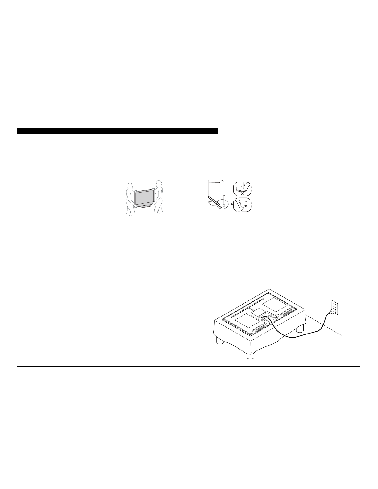
SETTING UP AND CARRYING THE TV
● Disconnect all cables when carrying the TV.
● Carry the TV with the adequate number of people; larger size TVs require two or more people.
● Correct hand placement while carrying the TV is very important for safety and to avoid damage.
USE CAUTION WHEN HANDLING THE LCD PANEL
When repairing the LCD panel, be sure you are grounded by using a wrist band.
When installing the LCD panel on a wall, the LCD panel must be secured using the 4 mounting holes on the rear cover.
1. Do not press on the panel or frame edge to avoid the risk of electric shock.
2. Do not scratch or press on the panel with any sharp objects.
3. Do not leave the module in high temperatures or in areas of high humidity for an extended period of time.
4. Do not expose the LCD panel to direct sunlight.
5. Avoid contact with water. It may cause a short circuit within the module.
6. Disconnect the AC power when replacing the backlight or inverter circuit.
(High voltage occurs at the inverter circuit at 650Vrms.)
7. Always clean the LCD panel with a soft cloth material.
8. Use care when handling the wires or connectors of the inverter
circuit. Damaging the wires may cause a short.
9. Protect the panel from ESD to avoid damaging the electronic
circuit (C-MOS).
10. During the repair, DO NOT leave the Power On for more than
1 hour while the TV is face down on a cloth.

KDL-32BX355/40BX455/46BX455 iv
CAUTIONS AND WARNINGS
CLEANING THE LCD PANEL
CAUTION: When cleaning the TV, be sure to unplug the power cord to avoid any chance of electric shock.
Clean the cabinet of the TV with a dry soft cloth.
Wipe the LCD screen gently with a soft cloth.
; Stubborn stains may be removed with a cloth slightly moistened with a solution of mild soap and warm water.
; If using a chemically pretreated cloth, please follow the instruction provided on the package.
; Never use strong solvents such as a thinner, alcohol or benzine for cleaning.
; Periodic vacuuming of the ventilation openings is recommended to ensure proper ventilation.
; Do Not use paper towels, any type of abrasive pad, rags, rubber or vinyl materials to clean the screen. Using these materials could easily scratch the
screen which may result in permanent damage.
; Do Not use any cleaning product containing alkaline/acid cleaner, scouring powder, or volatile solvent, such as alcohol, ammonia, benzine, thinner or
insecticide. Using any of these harsh cleaners may result in permanent damage to the screen.
; Do Not spray water or detergent directly onto the TV screen . If liquid drips into the bottom of the screen it may cause a failure.

KDL-32BX355/40BX455/46BX455 v
CAUTIONS AND WARNINGS
SAFETY CHECK-OUT
After correcting the original service problem, perform the following safety
checks before releasing the set to the customer:
1. Check the area of your repair for unsoldered or poorly soldered
connections. Check the entire board surface for solder splashes
and bridges.
2. Check the interboard wiring to ensure that no wires are “pinched” or
touching high-wattage resistors.
3. Check that all control knobs, shields, covers, ground straps, and
mounting hardware have been replaced. Be absolutely certain that
you have replaced all the insulators.
4. Look for unauthorized replacement parts, particularly transistors,
that were installed during a previous repair. Point them out to the
customer and recommend their replacement.
5. Look for parts which, though functioning, show obvious signs of
deterioration. Point them out to the customer and recommend their
replacement.
6. Check the line cords for cracks and abrasion. Recommend the
replacement of any such line cord to the customer.
7. Check the antenna terminals, metal trim, “metallized” knobs,
screws, and all other exposed metal parts for AC leakage. Check
leakage as described in “Leakage Test”.
LEAKAGE TEST
The AC leakage from any exposed metal part to earth ground and from all
exposed metal parts to any exposed metal part having a return to chassis,
must not exceed 0.5 mA (500 microamperes). Leakage current can be
measured by any one of three methods.
1. A commercial leakage tester.
Follow the manufacturers’ instructions provided with the tester.
2. A battery-operated AC milliammeter.
3. Measuring the voltage drop across a resistor by means of a VOM
or battery-operated AC voltmeter. The “limit” indication is 0.75 V, so
analog meters must have an accurate low voltage scale. Nearly all
battery-operated digital multimeters that have a 2 VAC range are
suitable. (see Figure A)
To Exposed Metal
Parts on Set
0.15 µF
Earth Ground
AC
Voltmete
r
(0.75V)
Figure A. Use an AC voltmeter to check AC leakage.
HOW TO FIND A GOOD EARTH GROUND
The cover-plate retaining screw on most AC outlet boxes is at earth ground.
Verify the AC outlet box retaining screw ground by connecting a 60W to
100W incandescent (not a neon or uorescent lamp) between the hot side of
the receptacle and the retaining screw. Try both slots, if necessary, to locate
the hot side on the line; the lamp should light at normal brilliance if the screw
is at ground potential. (see Figure B)
Figure B. Checking for earth ground.
Trouble Light
AC Outlet Box
KDL-32BX355/40BX455/46BX455 1
FEATURES
The AZ3TK chassis is one of several designs for the 2012 model line of
Sony Bravia® LCD televisions. This manual covers the following models:
KDL-32BX355
KDL-40BX455
KDL-46BX455
The BRAVIA® Sync™ BX series LED LCD HDTV
● Brilliant Full HD (1080p) picture quality
● Four HD inputs for a cable box, PS3™ and more1
● Share your pictures on the big screen via USB input
● Crisp detail & contrast w/ Clear Resolution Enhancer
● Optimized picture based on what you’re watching
● Less grain & a clear picture w/ Digital Noise Reduction
● Theater-like movie viewing with 24p True Cinema
● One remote for multiple devices with BRAVIA® Sync™2
SECTION 1 - FEATURES AND OVERVIEW
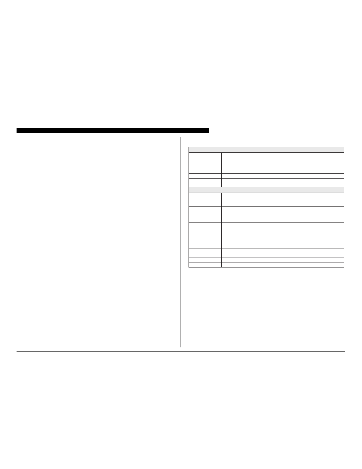
SPECIFICATIONS
Sistema
Sistema de televisã Analógico: NTSC/PAL-M/PAL-N
Digital: SBTVD-T
Cobertura de cana VHF: 2-13
UHF: 14-69
CATV: 1-135
Sistema do Painel Painel LCD (Tela de Cristal Líquido)
Potência de saída dos
Alto-falantes (RMS)
8 W + 8 W (127 V CA, THD*
1
10% sinal 1 KHz, Alto-falante de 8 Ohms, Nível de entrada
500 mVrms.)
Entradas/Saídas
CABLE/ANTENNA
VIDEO IN 1/2
ÁUDIO: 500 mVrms (Típico) / Impedância: 47 Kohms
COMPONENT IN
YPBPR (Vídeo componente): Y: 1,0 Vp-p, 75 ohms não balanceado, sincronizacão negativa /
P
B
: 0,7 Vp-p, 75 ohms
P
R
: 0,7 Vp-p, 75 ohms / Formato do sinal: 480i, 480p, 576i, 576p, 720p, 1080i, 1080p
ÁUDIO: 500 mVrms (Típico) / Impedância: 47 Kohms
HDMI IN 1/2
Áudio: Dois canais lineares PCM 32, 44,1 e 48 kHz, 16, 20 e 24bits, Dolby Digital
Entrada do PC
AUDIO OUT
DIGITAL AUDIO OUT
(OPTICAL)
Sinal óptico PCM/Dolby Digital
NI CP ovitisop ,smho 57 ,p-pV 7,0 ,BGR ocigólana ,nip-51 bus-D
Consulte o Capítulo de Referência de Sinal de Entrada do PC e HDMI IN
PC/HDMI IN 1 AUDIO IN
BSU Foto, Música e Vídeo
*1Distorcão Harmônica Total.
Terminal externo de 75 ohms para entradas RF
VÍDEO: 1 Vp-p, 75 ohms não balanceados, sincronizacão negativa
HDMI:Vídeo: 480i, 480p, 57 6i, 576p, 720p, 1080i, 1080p, 1080/24p
Saída de áudio, Fones de ouvido (minitomada)
Minitomada estéreo, 500 mVrms, (Típico) / Impedância: 47 Kohms
1. Cables sold separately.
2. Syncs with BRAVIA® Sync or Theatre Sync™ products.
KDL-32BX355/40BX455/46BX455 2
SECTION 1 - FEATURES AND OVERVIEW
•A disponibilidade dos acessórios opcionais depende do estoque.
•Projeto e especicacões técnicas sujeitos a alteracões sem prévio aviso.
•Os pesos e dimensões são aproximados.
Acessórios fornecidosControle remoto RM-YD081 (1)/Pilhas tamanho AA (2)/Manual de Instrucões (1)/Guia
Rápido (1)/Folheto de Instrucões de Seguranca (1)/Licenca de Software (1)/Fol heto Ginga
(1)/Guia de montagem do pedestal (1)/Pedestal (1 conjunto)/ Parafuso (3)
comum a todos os
modelos
Acessórios opcionais Cabos de conexão / Kit de cinto de seguranca
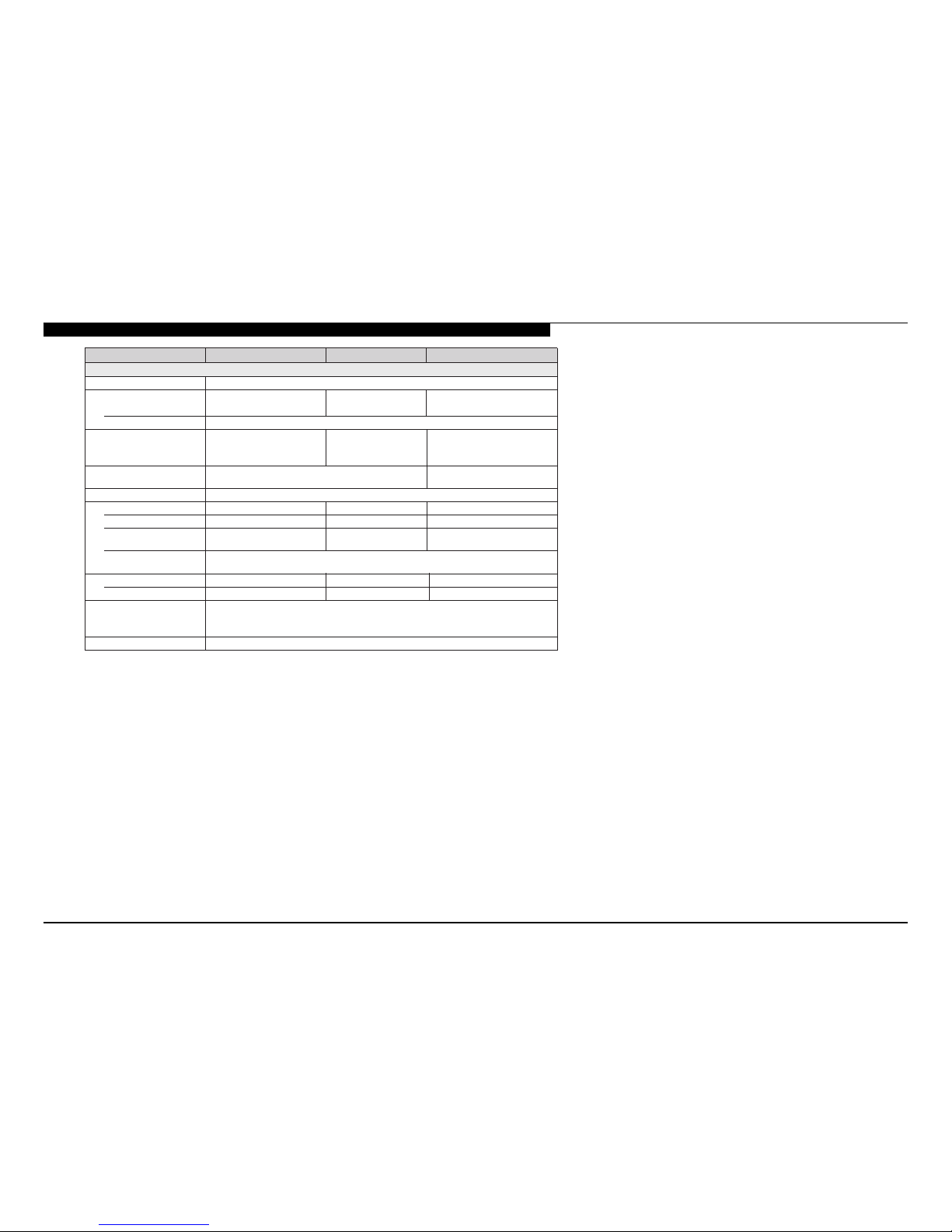
Nome do modelo KDL-46BX455 KDL-40BX455 KDL-32BX355
Energia e outros
Requisito de energia110-220 V CA, 60 Hz
Consumo de energia
W 901W 581W 781
em uso
em modo de esperaMenos do que 1 W
Tamanho da tela(cm)Aprox. 116,8 Aprox. 101,6 Aprox. 80,0
(polegadas medidas
diagonalmente)
)23 essalc( 5,130464
Resolucão da tela 1.920 pontos (horizontal) × 1.080 linhas (vertical) 1.366 pontos (horizontal) ×
768 linhas (vertical)
001 × 04)mm( )2( latot aerÁ/setnalaf-otlA
Dimensões com pedestal (mm) 1.112 × 713 × 278 980 × 639 × 220790 × 534 × 193
sem pedestal (mm)1.112 × 675 × 97980 × 601 × 94790 × 497 × 91
padrão do furo de montagem
da parede (mm)
300 × 300 300 × 300 200 × 200
tamanho do parafuso de
montagem da parede (mm)
M6 (comprimento: 8-12mm)
9,96,512,02)gk( latsedep mocoseP
3,95,416,71)gk( latsedep mes

KDL-32BX355/40BX455/46BX455 3
SECTION 1 - FEATURES AND OVERVIEW
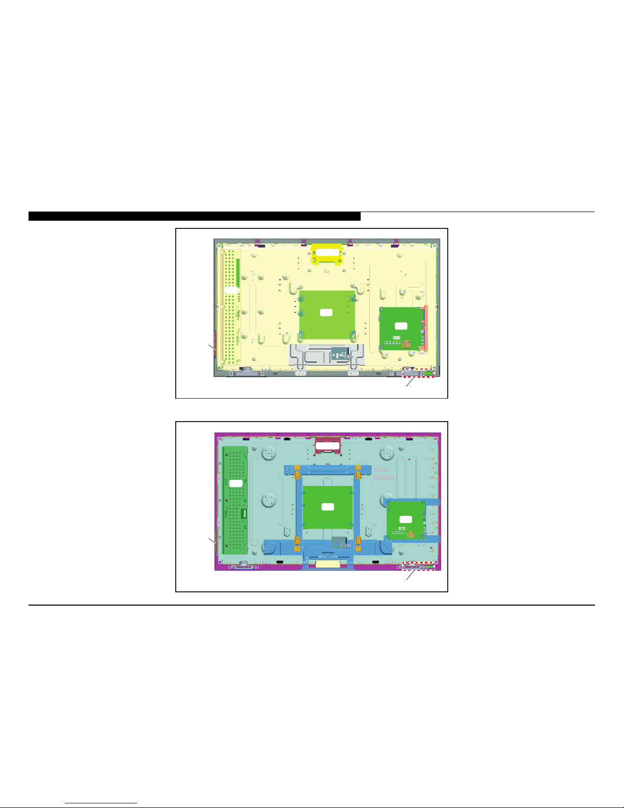
CHASSIS OVERVIEW
The primary circuits in the AZ3TK chassis consist of a Main Board (A Board), Power Supply Board (G Boards), the IR Board (H Board), the Switch Unit, and
the LCD Panel Assembly which includes the TCON Board and the Inverter MT Board.
NOTE: For connector part number information, refer to “Connectors” on page 19. For Wire Dressing information, refer to “Wire Dressing” on page 21.
SWITCH
UNIT
INV
A
G
H
BOARD LAYOUT FOR KDL-32BX355 ONLY
KDL-32BX355/40BX455/46BX455 4
SECTION 1 - FEATURES AND OVERVIEW
SWITCH
UNIT
INV
A
G
TCON
H
BOARD LAYOUT FOR KDL-40BX455 ONLY
SWITCH
UNIT
INV
A
G
TCON
H
BOARD LAYOUT FOR KDL-46BX455 ONLY
 Loading...