

Page 1

LCD Digital
Color TV
Sony Customer Support
U.S.A.: www.sony.com/tvsupport
Canada: www.sony.ca/support
Operating Instructions
KDL-52XBR9
KDL-46XBR9
KDL-40XBR9
© 2009 Sony Corporation
United States
1.800.222.SONY
Please Do Not Return
the Product to the Store
Canada
1.877.899.SONY
Page 2
Owner’s Record
The model and serial numbers are located at the rear of the TV.
Record these numbers in the spaces provided below. Refer to
them whenever you call upon your Sony dealer regarding this
TV.
Model Name
Serial No.
CAUTION
To prevent electric shock and blade exposure, do not use
this polarized A C plug with an extension cord , receptacle or
other outlet unless the blades can be fully inserted.
❑ Operate the TV only on 120-240 V AC.
❑ Avoid operating the TV at temperatures below 41°F
(5°C).
Licensing Information
Macintosh is a trademark of Apple Inc., registered in the U.S. and
other countries.
HDMI, the HDMI logo and High-Definition Multimedia Interface
are trademarks or registered trademarks of HDMI Licensing, LLC.
Fergason Patent Properties, LLC:
U.S. Patent No. 5,717,422
U.S. Patent No. 6,816,141
Manufactured under license from Dolby Laboratories. Dolby and
the double-D symbol are trademarks of Dolby Laboratories.
In the United States, TV Guide and other related marks are
trademarks of Gemstar-TV Guide International, Inc. and/or its
subsidiaries. In Canada, TV Guide is a registered mark of
Transcontinental Inc., and is used under license by Gemstar-TV
Guide International, Inc. and/or its subsidiaries.
The TV Guide On Screen system is manufactured under license
from Gemstar-TV Guide International, Inc. and/or its subsidiaries.
The TV Guide On Screen system is protected by one or more of the
following United States patents 6,498,895; 6,850,693; 6,396,546;
5,940,073; 6,239,794 to Gemstar-TV Guide International, Inc. and/
or its subsidiaries.
Gemstar-TV Guide Internationa l, Inc. and/or its related affiliates are
not in any way liable for the accuracy or availability of the program
schedule information or other data in the TV Guide On Screen
system and cannot guarantee service availability in your area. In no
event shall Gemstar-TV Guide International, Inc. and/or its related
affiliates be liable for any damages in connection with the accuracy
or availability of the program schedule information or other data in
the TV Guide On Screen system.
Blu-ray Disc is a trademark.
“BRAVIA” and , S-Force, Motionflow, BRAVIA Sync,
x
and “x.v. Color” are trademarks or registered marks of
, DMe
Sony Corporation.
“XrossMediaBar” is a trademark of Sony Corporation. “XMB” is a
trademark of Sony Corporation and Sony Computer Entertainment
Inc.
“PlayStation” is a registered trademark and “PS3” is a trademark of
Sony Computer Entertainment Inc.
®
, the DLNA Logo and DLNA CERTIFIED™ are
DLNA
trademarks, service marks, or certification marks of the Digital
Living Network Alliance.
®
Your BRAVIA TV is ENERGY STAR
in the “Home” mode.
It meets strict energy efficiency guidelines set by
the U.S. Environmental Protection Agency and
Department of Energy. ENERGY STAR is a joint
program of these government agencies, designed
to promote energy efficient products and
practices.
Changes to certain features, settings, and functionalities of this TV
(i.e. TV Guide, Picture/Sound, Light Sensor, Power Savings) can
increase or change the power consumption.
Depending upon such changed settings, the power consumption
may exceed the limits required for the ENERGY STAR
qualification in the “Home” mode.
qualified
This manual is for the 40, 46 and 52 inch BRAVIA KDL-XBR9 series models with screen size measured diagonally.
2
Page 3
Contents
Introducing Your BRAVIA® TV
Experiencing Stunning HD with
Your BRAVIA TV . . . . . . . . . . . . . . . . . . . . .4
The Four Steps to a Full HD Experience . . . . 4
TV Feature Highlights . . . . . . . . . . . . . . . . . . .5
Getting Started
Setting Up Your TV. . . . . . . . . . . . . . . . . . . . . 6
Using a Wall-Mount Bracket . . . . . . . . . . . . . .7
Locating Inputs and Outputs . . . . . . . . . . . . . .8
Connecting the TV . . . . . . . . . . . . . . . . . . . .10
Connecting Internet & DLNA Certified™
Networks. . . . . . . . . . . . . . . . . . . . . . . . . . .13
Connecting Other Equipment . . . . . . . . . . . .14
Bundling the Connecting Cables. . . . . . . . . .15
Installing the TV Against a Wall or
Enclosed Area . . . . . . . . . . . . . . . . . . . . . .15
Securing the TV . . . . . . . . . . . . . . . . . . . . . .16
Running Initial Setup. . . . . . . . . . . . . . . . . . .18
Operating the TV
Using the Remote Control. . . . . . . . . . . . . . . 19
Remote Control Button Description . . . . . . .20
TV Controls and Indicators . . . . . . . . . . . . . .23
Programming the Remote Control . . . . . . . .24
Manufacturer’s Code List . . . . . . . . . . . . . . .25
Using Other Equipment with Your
Remote Control. . . . . . . . . . . . . . . . . . . . . .27
Remote Control Backlight . . . . . . . . . . . . . . .28
Exploring the XMB™ and TV
Features
Category Icons . . . . . . . . . . . . . . . . . . . . . . .30
Accessing Photo, Music, and Video
Content . . . . . . . . . . . . . . . . . . . . . . . . . . . .31
BRAVIA Internet Video . . . . . . . . . . . . . . . . .32
Photo, Music, and Video . . . . . . . . . . . . . . . .33
BRAVIA Internet Widgets . . . . . . . . . . . . . . . 35
Favorites . . . . . . . . . . . . . . . . . . . . . . . . . . . . 37
TV Guide On Screen
Background TV . . . . . . . . . . . . . . . . . . . . . . . 40
Inputs . . . . . . . . . . . . . . . . . . . . . . . . . . . . . . 40
Wide Mode . . . . . . . . . . . . . . . . . . . . . . . . . .41
BRAVIA Sync with Control for HDMI . . . . . .43
®
. . . . . . . . . . . . . . . . .38
Other Information
How to Care for Your BRAVIA . . . . . . . . . . .44
Troubleshooting . . . . . . . . . . . . . . . . . . . . . .44
Specifications . . . . . . . . . . . . . . . . . . . . . . . . 46
Index . . . . . . . . . . . . . . . . . . . . . . . . . . . . . . . 47
Welcome to the World of BRAVIA
Thank you for purchasing this Sony
BRAVIA® high-definition television. Use the
®
HDTV
documentation listed below to get the most out of your TV.
Safety Booklet
Provides precautionary
measures to keep you and your
TV safe. Read this information
prior to setting up your TV.
Operating Instructions
Provides general TV operation
information.
Quick Setup Guide
Provides TV setup information,
illustrates sample optional
equipment connection diagrams,
and highlights TV features.
Reference Book
Offers the most complete TV
operation information available for
your TV and presents advanced
customization details. Access it at
www.sony.com/referencebook
The TV operation information above has been designed in an eco-friendly
manner to reduce the consumption of natural resources.
.
3
Page 4
Introducing Your BRAVIA® TV
Experiencing Stunning HD with Your BRAVIA TV
To experience the stunning detail of your new
(HD) programming. Your
• Over-the-air broadcasting via HD-quality antenna
• HD cable subscription
• HD satellite subscription
• Blu-ray Disc™ player or other HD compatible external equipment
Contact your cable, satellite or HD service provider for information on upgrading to HD
programming.
BRAVIA
TV can receive and display HD programming from:
BRAVIA
TV, you need access to high-definition
The Four Steps to a Full HD Experience
Set, Source, Sound, and Setup
Along with your BRAVIA TV set, a complete HD system requires a source of HD
programming, an HD sound system, and a proper connection setup. Refer to the Quick
Setup Guide, enclosed separately, for connecting other optional equipment.
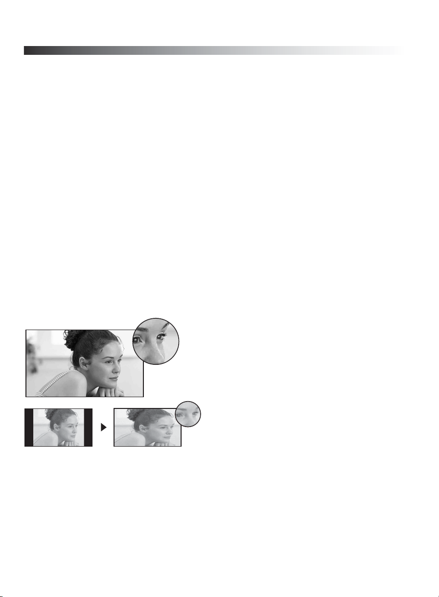
You can enjoy crisp, clear images, smooth
movement, and high-impact visuals from
1080 HD signals as shown here.
When you compare a high-definition signal to
a standard definition signal, you will notice a
big difference in picture quality. If black bars
appear as shown here, press WIDE on the
remote control to fill the screen.
4
Page 5
TV Feature Highlights
Yo u r BRAVIA TV is equipped with the latest in TV technology.
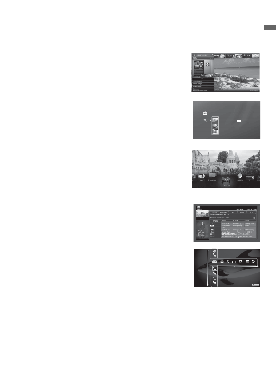
➢ Broadband Internet Connectivity: BRAVIA Internet
Video brings videos, movies and much more from the
Internet to your TV (page 32). BRAVIA Internet Widgets
allow you to access local weather, news, and much more.
Displayed here is Widgets (page 35).
Introducing Your BRAVIA
➢ Digital Media Accessibility: Use the Photo, Music, and
Video Category icons to access photo, music, and video
files from DLNA Certified
TM
networked equipment or Sony
USB equipment. Displayed here is Photo USB (page 33).
➢ Central Location for Your Favorite Items: The
Favorites feature centralizes your favorite BRAVIA
Internet Video and Widgets items, Photo, Music, Video
content, TV channels, External Inputs, and Background
TV themes for quick and easy access (page 37).
➢ Channel Programming Information: TV Guide On
Screen
➢ TV Home Menu: XMB
®
provides TV programming information (page 38).
TM (XrossMediaBar) TV menu
provides you access to TV settings, photo, music, video,
TV channel listings, and more (page 29).
®
TV
Photo
DSC02991
JPG
Fri 5/25/2007 12:06 PM
DSC00140.JPG
DSC00141.JPG
Product Support
Preferences
Settings
Picture & Display
Sound
Channel & Inputs
Network
TV
5
Page 6
Getting Started
Setting Up Your TV
Some TV models are packaged with a detached Table-Top Stand so you can mount your TV to a
wall right away. If you are not mounting the TV to a wall, you will need to attach the Table-Top
Stand. You will need a Phillips screwdriver and the supplied screws to complete the task. Look for
the attachment instructions taped to the TV unit.
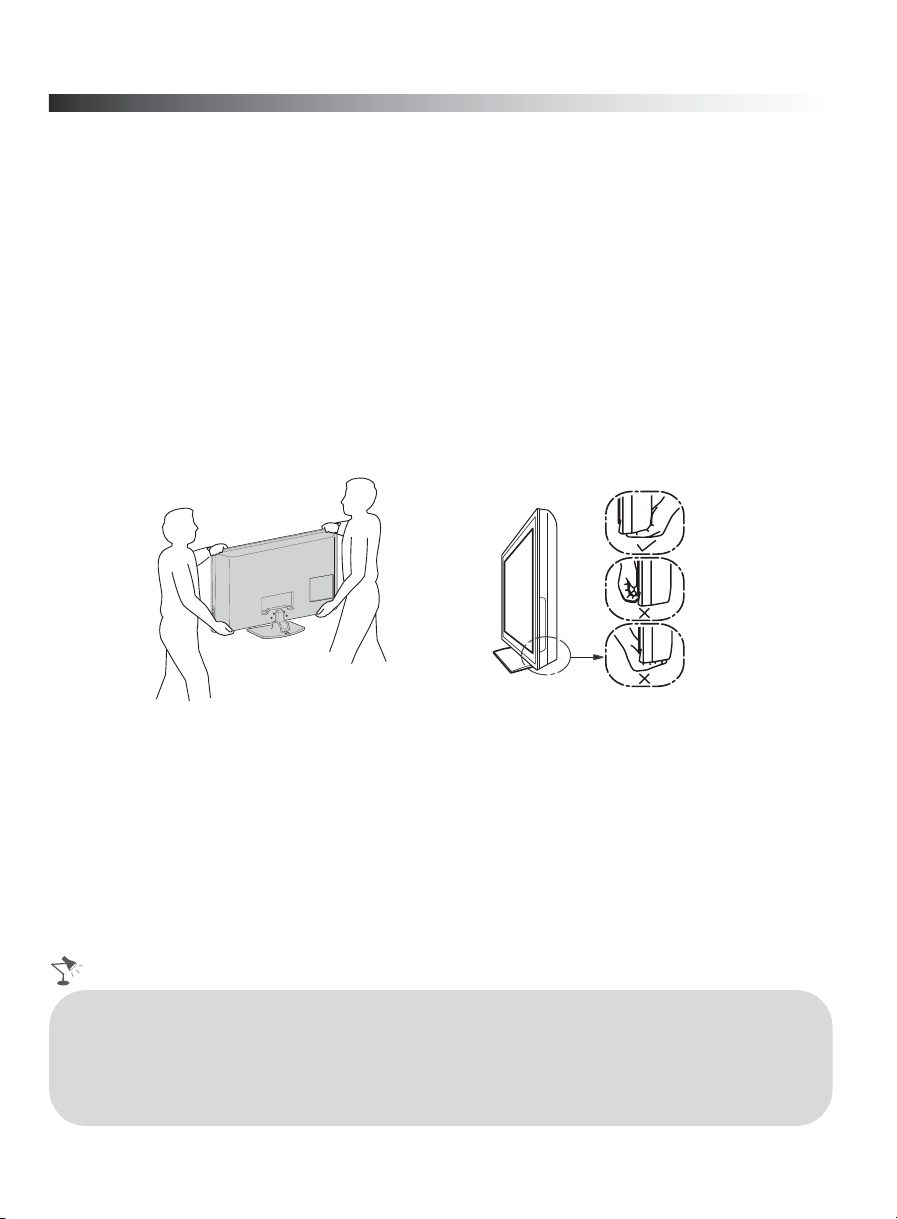
Be sure to consider the following while setting up your TV:
• Disconnect all cables when carrying the TV.
• Carry the TV with the adequate number of people; larger size TVs require two or more people.
• Correct hand placement while carrying the TV is very important for safety and to avoid
damages.
• Ensure your TV has adequate ventilation, see page 15.
• For best picture quality, do not expose the screen to direct illumination or sunlight.
• Avoid installing the TV in a room with reflective wall and floor materials.
• Avoid moving the TV from a cold area to a warm area. Sudden room temperature changes may
cause moisture condensation. This may cause the TV to show poor picture and/or poor color.
Should this occur, allow moisture to evaporate completely before powering the TV on.
• Read the supplied Safety Booklet for additional safety information.
• When cable connection is completed, be sure to secure the TV to a stable surface or mount it to a
wall. The designated Sony wall-mount bracket model and TV stand model name(s) are available
under the “Other Information” section of Operating Instructions. For details on securing the TV,
see page 16.
6
Page 7
Using a Wall-Mount Bracket
All models except the 52 inch (measured diagonally) model can be mounted to a wall using the
Wall-Mount Bracket (not supplied) out of the box as packaged.
If you are mounting the 52 inch model to a wall, remove the Table-Top Stand. For removing the
Table-Top Stand, refer to the instructions attached to the TV.
Prepare the TV for the Wall-Mount Bracket before making cable connections.
Sony strongly recommends that you use the Wall-Mount Bracket model designed for your
TV (see page 45) and that wall-mounting of your TV should be performed by a Sony dealer
or licensed contractor.
• Follow the instruction guide provided with the Wall-Mount Bracket for your model. You
may also need to refer to the online Reference Book for additional information for your TV
model. Sufficient expertise is required in installing this TV, especially to determine the
strength of the wall for withstanding the TV’s weight.
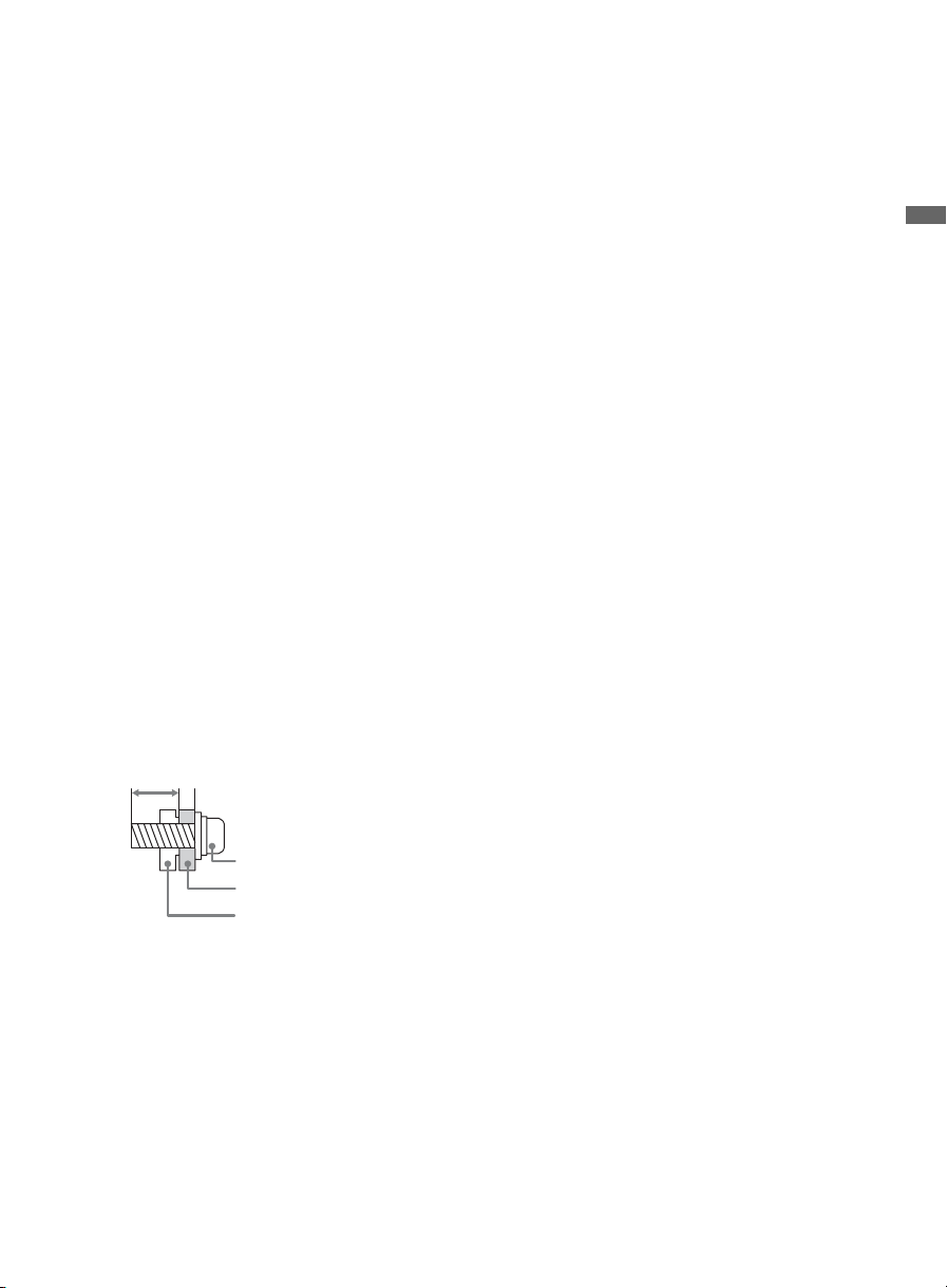
• Be sure to use the screws supplied with the Wall-Mount Bracket when attaching the
mounting hooks to the TV set. (Do not use the screws that are intended for the Table-Top
Stand attachment.)
The supplied M6 screws are designed so that they are 8 mm to 12 mm in length when
measured from the attaching surface of the mounting hook.
The diameter and length of the screws differ depending on the Wall-Mount Bracket model.
Use of screws other than those supplied with the bracket may result in internal damage to
the TV set or cause it to fall, etc.
Getting Started
8-12 mm
M6 screw (supplied with the Wall-Mount Bracket)
Mounting Hook
Rear of the TV set
• Be sure to store the unused screws and Table-Top Stand in a safe place until you are ready
to attach the Table-Top Stand. Keep the screws away from small children. When you are
using the Table-Top Stand, be sure to read page 17.
7
Page 8
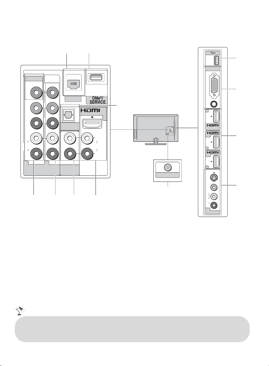
Locating Inputs and Outputs
LAN
5
2
(OPTICAL)
7
IN
1
L
AUDIO
R
6
Rear Panel
VIDEO IN
VIDEO
Y
P
B
P
R
L
AUDIO
R
1 2
COMPONENT IN
(1080p/1080i/720p/480p/480i)
34
1
DIGITAL
AUDIO OUT
AUDIO
AUDIO OUT
(VAR/FIX)
CABLE / ANTENNA
8
Side Panel
PC IN
RGB
AUDIO
2
IN
IN
3
IN
4
S
VIDEO
VIDEO
L
(MONO)
AUDIO
R
2
VIDEO IN
9
0
6
qa
• An HDMI or Component video (YPBPR ) connection is required to view 480i, 480p, 720p, 1080i
and 1080p video formats. The 1080/24p video format is available only with HDMI connection.
This TV displays all video input signals in a resolution of 1,920 dots × 1,080 lines.
8
Page 9

Item Description
1 LAN Connects to an existing network using an Ethernet cable. Be sure to complete
Network Setup (page 18).
x
2 DMe
3 VIDEO IN 1/
4 COMPONENT
/SERVICE This USB port is only for service unless you are connecting an optional BRAVIA
Link module (DMe
x
).
This input port can be used as composite video input (VIDEO 1) or as component
COMPONENT
IN 1 (1080p/
1080i/720p/
480p/480i)/
L-AUDIO-R
video input (COMPONENT 1). For composite use, connect the yellow jack to Y for
video and use audio (L/R) for audio signals. For component connection, use Y, P
PR for video signals and also connect the audio (L/R) for audio signals.
By default, this TV will automatically detect and switch between VIDEO 1 and
COMPONENT 1. To manually set the input type, press HOME, select Settings,
then Channels & Inputs, then select Video/Component 1 Selection.
Component video provides better picture quality than the S Video and composite
IN 2
video.
Audio connection is required for the COMPONENT IN ports, connect audio (L/R).
5 AUDIO OUT
(VAR/FIX)
6 HDMI IN 1/2/3/4
L-AUDIO-R
Connects to the left and right audio input jacks of your analog audio equipment. You
can use these outputs to listen to your TV’s audio through your stereo system.
HDMI (High-Definition Multimedia Interface) provides an uncompressed, alldigital audio/video interface between this TV and any HDMI-equipped audio/video
equipment, such as a set-top box, DVD player, and A/V receiver. HDMI supports
enhanced, or high-definition video, plus digital audio. Be sure to use only an HDMI
cable that bears the HDMI logo.
Use the HDMI IN 1 port when connecting DVI equipment with a DVI-to-HDMI
cable or adapter (not supplied). Equipment using a DVI connection also requires an
additional audio connection using an audio cable connected to AUDIO (L/R).
7 DIGITAL AUDIO
OUT (OPTICAL)
8 CABLE/
Connects to the optical audio input of digital audio equipment that is PCM/Dolby*
Digital compatible.
RF input that connects to your cable or over-the-air antenna.
ANTENNA
9 USB Connects to USB equipment to access photo, music, and video files.
0 PC IN
(RGB/AUDIO)
Connects to a personal computer’s video and audio output connector. Can also be
connected to other analog RGB equipment.
For some Apple Macintosh computers, it may be necessary to use an adapter (not
supplied). If an adapter is used, connect the adapter to the computer before
connecting the HD15-HD15 cable.
You may need to adjust the TV settings or your PC’s resolution and timing (see
page 12).
qa VIDEO IN 2
S VIDEO/VIDEO
L (MONO)AUD IO- R
* Manufactured under license from Dolby Laboratories. Dolby and the double-D symbol are trademarks of Dolby
Laboratories.
Connects to the S VIDEO output jack of video equipment. If both composite video
and S VIDEO are connected, S VIDEO signal has priority.
If you have mono equipment, connect its audio output port to the TV’s L (MONO)
audio input port.
Getting Started
,
B
9
Page 10
Connecting the TV
Cable System or VHF/UHF Antenna System
You can enjoy high-definition and standard-definition digital programming (if available in your
area) along with standard-definition analog programming.
This TV is capable of receiving unscrambled digital programming for both cable (QAM and
8VSB) and external VHF/UHF antenna (ATSC).
Cable or VHF/UHF (or VHF only)
75-ohm coaxial cable Rear of TV
CABLE/ANTENNA
• It is strongly recommended that you connect the CABLE/ANTENNA input using a 75-ohm
coaxial cable to receive optimum picture quality. A 300-ohm twin lead cable can easily be affected
by radio frequency interference, resulting in signal degradation.
Cable System and VHF/UHF Antenna System
Use an optional A-B RF switch (not
supplied) to switch between the cable
and over-the-air antenna programming,
as shown here.
Set the Cable/Antenna setting found
under the Settings on the XMB
to Cable or Antenna for the type of input signal you choose.
™
Cable
Antenna
A-B RF Switch
A
B
Rear of TV
CABLE/ANTENNA
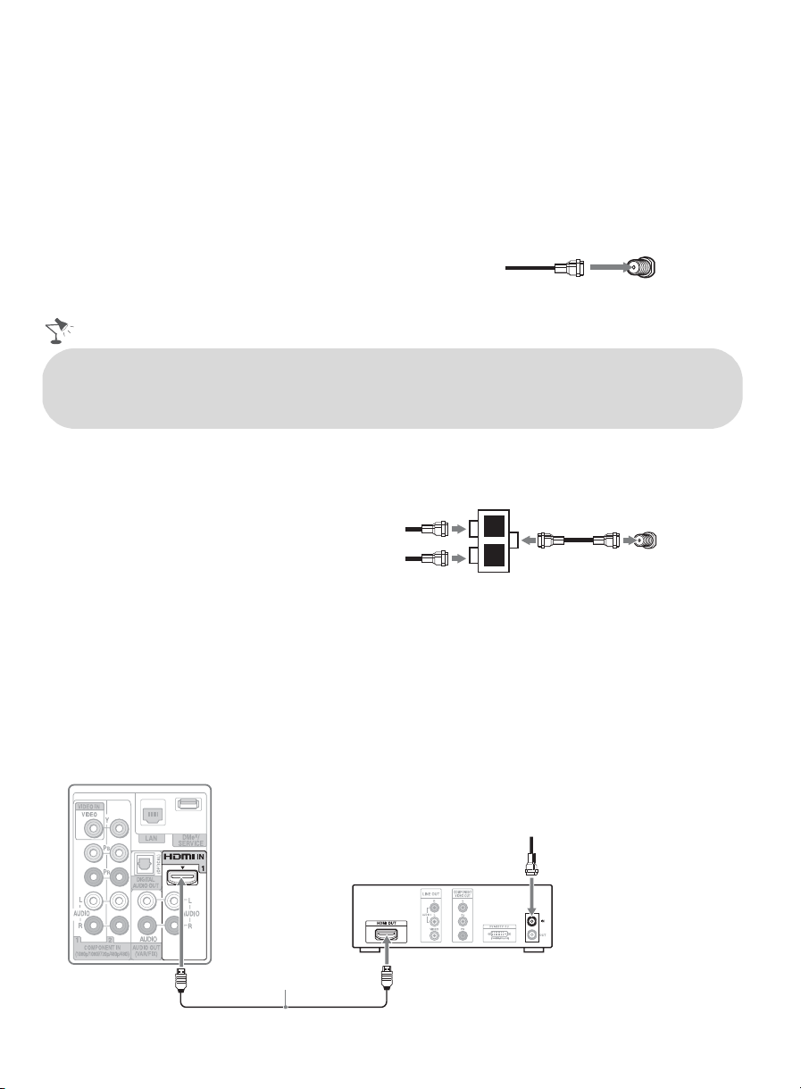
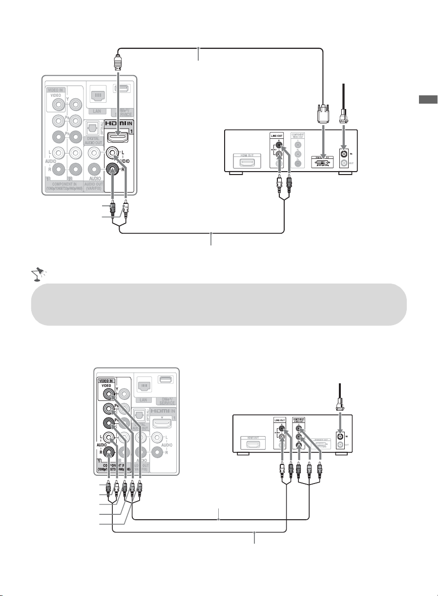
HD Cable Box/HD Satellite Box
You can enjoy high-definition programming by subscribing to a high-definition service or a highdefinition satellite service. For the best possible picture, make sure you connect this equipment to
your TV via the HDMI or component video (with audio) input located on the back of your TV.
Shown with HDMI Connection
Rear of TV
CATV/Satellite antenna cable
HD cable box/
HD satellite box
HDMI cable
10
Page 11
Shown with DVI Connection
Rear of TV
DVI-to-HDMI cable
CATV/
Satellite
antenna
cable
HD cable box/
HD satellite box
AUDIO-R (red)
AUDIO-L (white)
Audio cable
• If your equipment has a DVI output and not an HDMI output, connect the DVI output to the
HDMI IN 1 (with DVI-to-HDMI cable or adapter) and connect the audio output to the AUDIO
IN (L/R) of HDMI IN 1.
Shown with Component Connection
Rear of TV
CATV/Satellite antenna cable
Getting Started
AUDIO-R (red)
AUDIO-L (white)
P
(red)
R
P
(blue)
B
Y (green)
HD cable box/
HD satellite box
Component video cable
Audio cable
(Continued)
11
Page 12
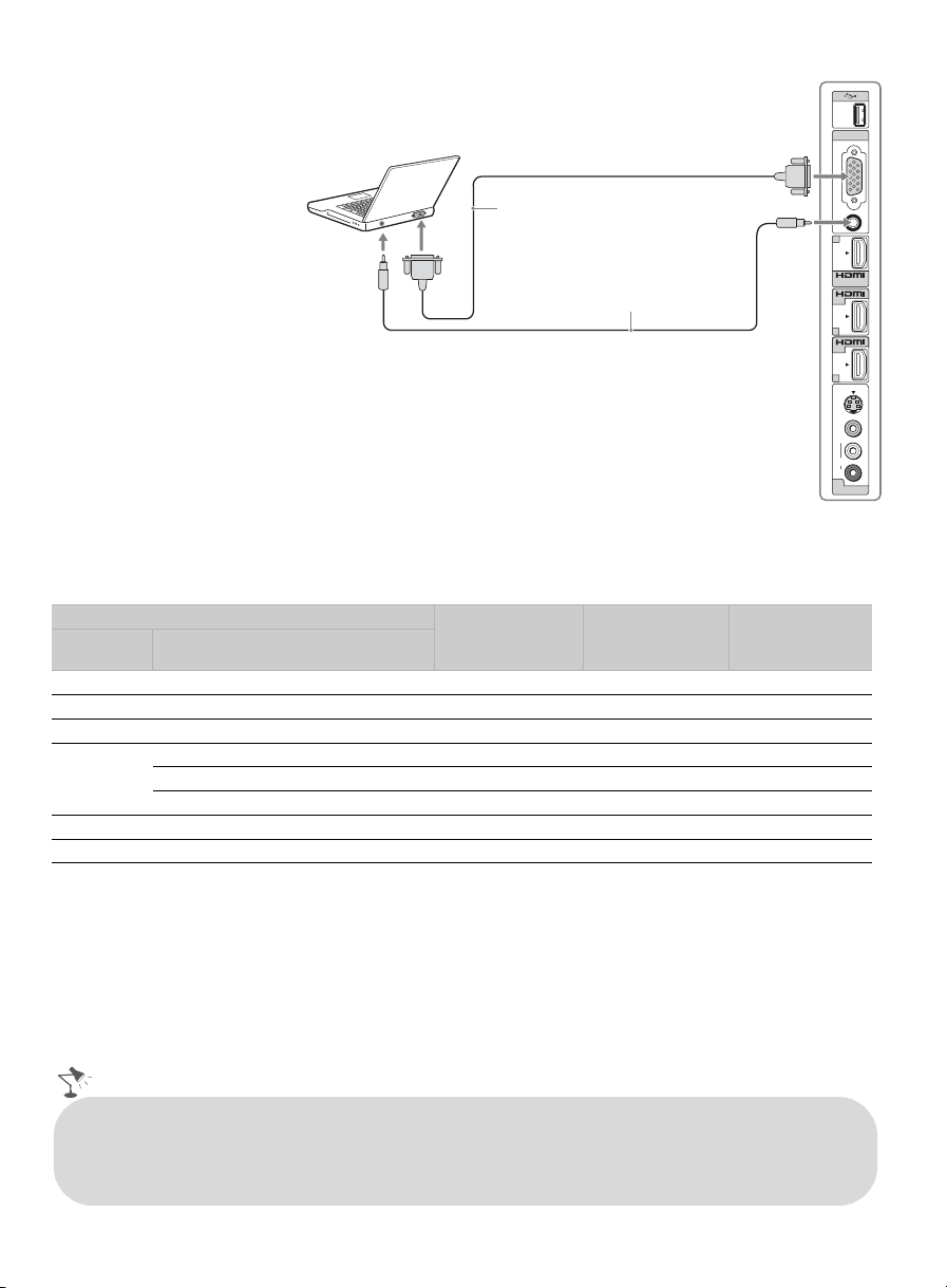
Shown with PC connection
Side panel
Use the TV as a monitor for
your PC by connecting an
PC IN
RGB
HD15-HD15 cable
connection as shown to the
right.
This TV can also be
connected to a PC with a
DVI or HDMI output.
(Refer to the supplied Quick
Setup Guide.)
HD15-HD15 cable
(analog RGB)
Audio cable
(stereo mini plugs)
AUDIO
2
IN
IN
3
IN
4
VIDEO
VIDEO
(MONO)
AUDIO
S
L
R
2
VIDEO IN
PC Input Signal Reference Chart
After connecting the PC to the TV, set the output signal from your PC according to the supported
resolutions and timings indicated below.
Supported resolutions
Signal Horizontal
(Pixel)
VGA 640
SVGA
XGA
WXGA
SXGA
HDTV*
800
1,024
1,280
1,280
1,360
1,280
1,920
× Vertical
(Line)
×
×
×
×
×
×
×
×
480 31.5 60 VGA
600 37.9 60 VESA Guidelines
768 48.4 60 VESA Guidelines
768 47.4 60 VESA
768 47.8 60 VESA
768 47.7 60 VESA
1,024 64.0 60 VESA
1,080 67.5 60 CEA-861*
Horizontal
frequency (kHz)
Vertical
frequency (Hz)
Standard
~
• This TV’s PC input does not support Sync on Green or Composite Sync.
• This TV’s PC VGA input does not support interlaced signals.
• For the best picture quality, it is recommended to use the signals in the above chart. In plug and play, signals
with a 60 Hz vertical frequency will be detected automatically. (PC reboot may be necessary.)
* The 1080p timing when applied to the HDMI input will be treated as a video timing and not PC timing. This
affects Picture settings and Wide Mode settings. To view PC content set Scene Select to Graphics,
Wide Mode to Full, and Display Area to Full Pixel.
• Connect the PC IN jack to the PC using an HD15-HD15 cable with ferrite core (analog RGB) and
audio cable (see page 9).
• The TV enters the standby mode automatically when the PC is connected to the TV and no signal
has been output from the PC for more than 30 seconds, see the online Reference Book for details.
12
Page 13
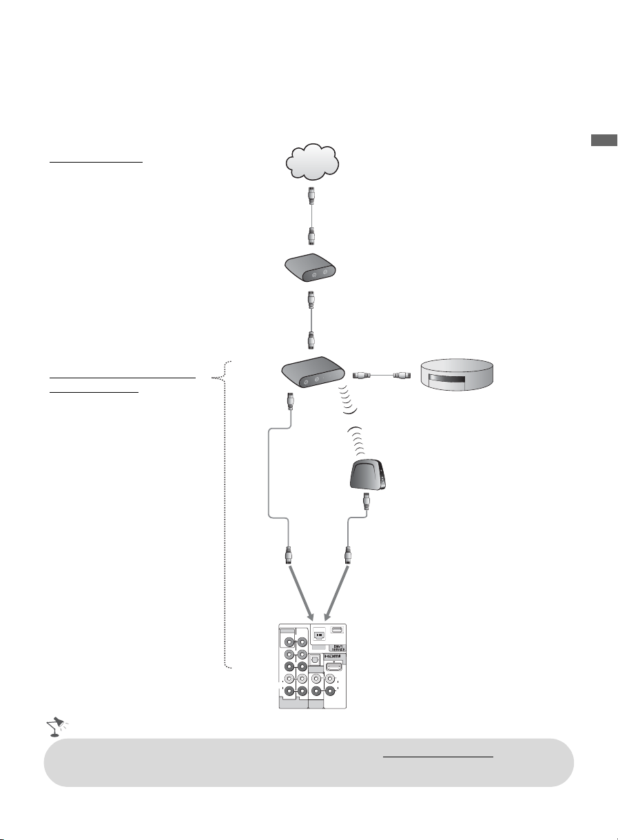
Connecting Internet & DLNA Certified™ Networks
R
N
R
R
Connect an Ethernet cable from your home network to the LAN input of your TV to enjoy
BRAVIA Internet features and/or connect to DLNA Certified™ media servers, see page 31 to
learn more about these features.
Sample Network Connection Diagram
Internet Features
• BRAVIA Internet Video
• BRAVIA Internet Widgets
DLNA Certified™ Media
Player Features
• Photo
•Music
•Video
Internet
Modem
Router
INTERNET
POWER
PORT 3
PORT 2
PORT 1
POWER
or
!
Getting Started
PORT 4
DLNA Certified™ Media Server
Wireless Bridge
VIDEO IN
VIDEO
Y
LAN
P
B
P
R
L
AUDIO
R
1 2
COMPONENT IN
(1080p/1080i/720p/480p/480i)
DIGITAL
AUDIO OUT
AUDIO
AUDIO OUT
(VAR/FIX)
(OPTICAL)
AUDIO
IN
1
L
R
• For more information about compatible wireless bridges, visit https://internet.sony.tv
• Refer to your DLNA Certified equipment’s operating instructions for setup and connection
information.
13
Page 14
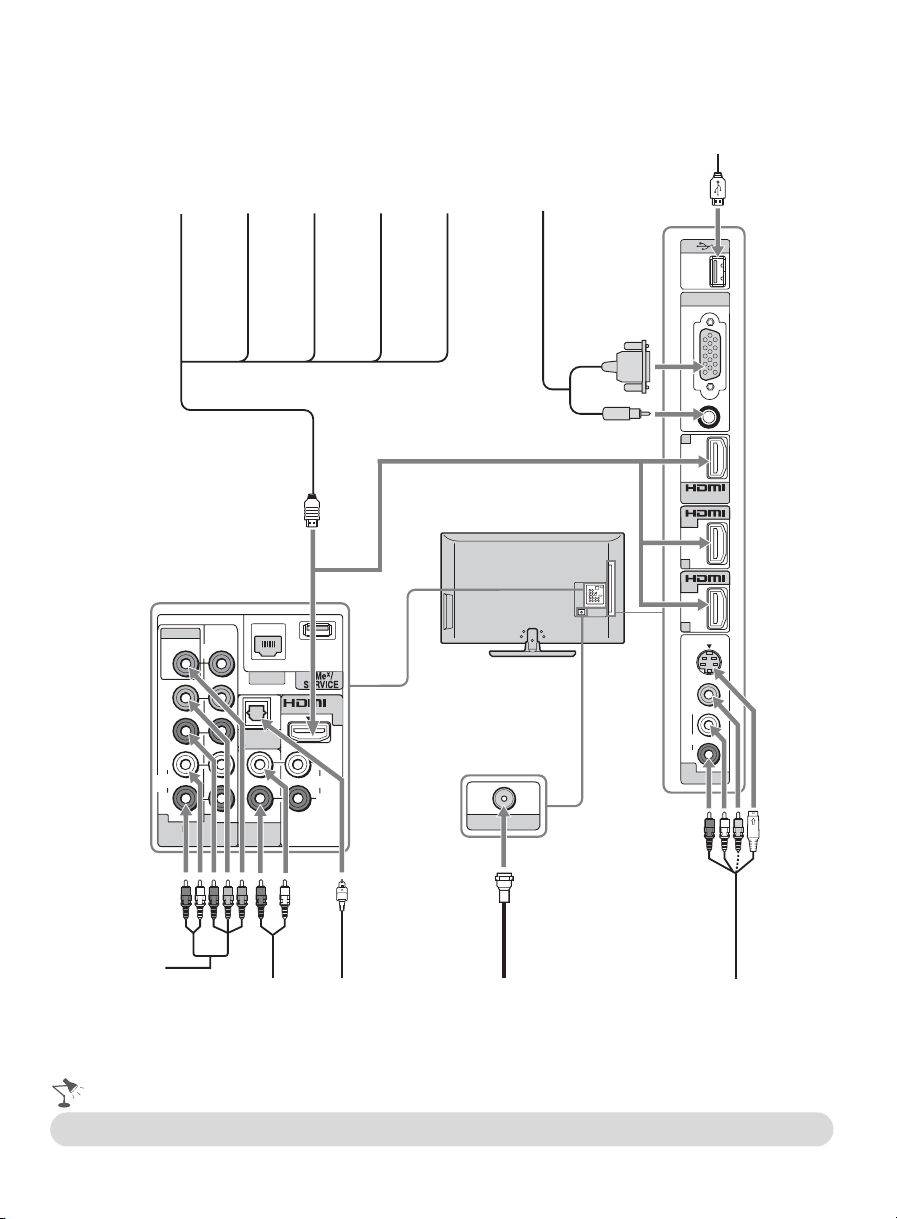
Connecting Other Equipment
Blu-ray
Disc Player/
“PS3”
VIDEO IN
VIDEO
Y
P
B
P
R
L
AUDIO
R
1 2
COMPONENT IN
(1080p/1080i/720p/480p/480i)
DVD
player
LAN
DIGITAL
AUDIO OUT
AUDIO
AUDIO OUT
(VAR/FIX)
Digital
satellite
receiver
(OPTICAL)
AUDIO
L
R
IN
1
Digital
cable box
Audio
system
CABLE / ANTENNA
Personal
computer
PC IN
RGB
AUDIO
2
IN
IN
IN
3
IN
IN
4
S
VIDEO
VIDEO
L
(MONO)
AUDIO
R
2
VIDEO IN
USB
Digital
recorder
Analog audio
equipment
Digital audio
equipment
CABLE/ANTENNA
(A/V Receiver/Home Theater)
• Refer to the Quick Setup Guide (supplied) when connecting other equipment to your TV.
14
VCR/
Game system/
Camcorder
Page 15
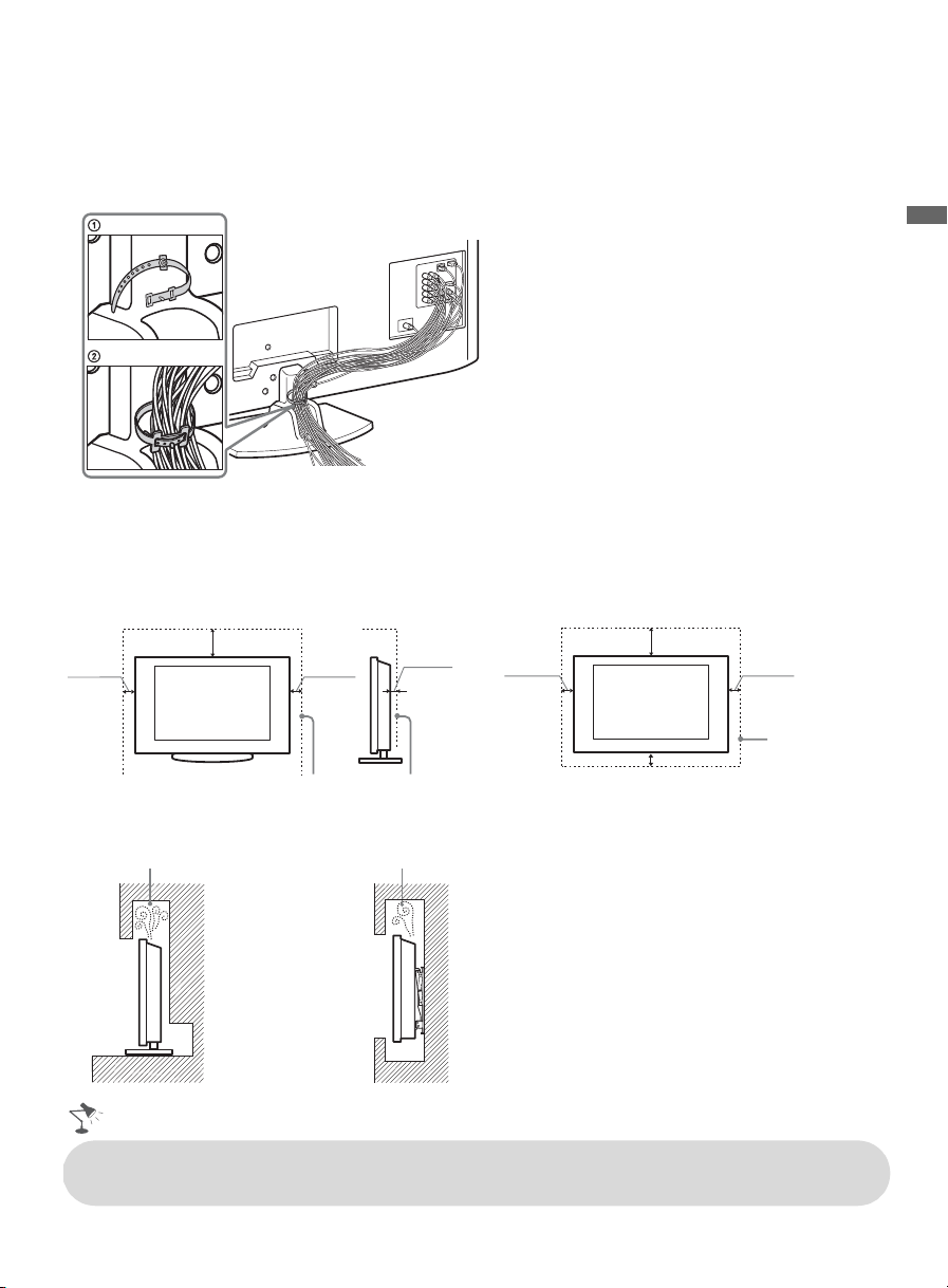
Bundling the Connecting Cables
Use the attached cable clamper to bundle the connecting cables. The cable clamper is located on
the Table-Top Stand as illustrated. Refer to the online Reference Book when mounting the TV to a
wall.
Do not bundle the AC power cord with other connecting cables.
Installing the TV Against a Wall or Enclosed Area
Make sure that your TV has adequate ventilation. Allow enough space around the TV as shown
below. Avoid operating the TV at temperatures below 41 °F (5 °C).
Installed with stand
7
/
inches
11
8
4 inches
(10 cm)
Leave at least this much space around the set.
(30 cm)
4 inches
(10 cm)
3
inches
2
/
8
(6 cm)
Installed on the wall
11
4 inches
(10 cm)
4 inches (10 cm)
7
/
8
(30 cm)
inches
4 inches
(10 cm)
Leave at least
this much space
around the set.
Getting Started
Never install the TV set as follows:
Air circulation is blocked.
Wall
• Inadequate ventilation can lead to overheating of the TV and may cause TV damage or cause
a fire.
Air circulation is blocked.
Wall
15
Page 16

Securing the TV
Sony strongly recommends taking measures to prevent the TV from toppling over.
Unsecured TVs may topple and result in property damage, serious bodily injury or even
death.
Preventing the TV from Toppling
❑ Secure the TV to a wall and/or stand.
❑ Do not allow children to play or climb on furniture and TV sets.
❑ Avoid placing or hanging items on the TV.
❑ Never install the TV on:
• slippery, unstable and/or uneven surfaces.
• furniture that can easily be used as steps, such as a chest of drawers.
❑ Install the TV where it cannot be pulled, pushed, or knocked over.
❑ Route all AC power cords and connecting cables so that they are not accessible to curious
children.
Recommended Measures to Secure the TV
Consider the following measures when securing your TV to a TV stand (not supplied).
1 Secure the stand for the TV.
Make sure the TV stand can adequately support the weight of the TV. Use two angle braces
(not supplied) to secure the stand.
For each angle brace use the appropriate hardware to:
• attach one side of the angle brace to the wall stud.
• attach the other side to the TV stand.
16
Angle brace
Stand
Page 17

2 Secure the TV to the stand.
Use the optional hardware listed below (not supplied):
• M4 × 20 machine screw (screwed into the TV’s Table-Top Stand).
• A screw or similar (attach it to the TV stand).
• Rope or chain (strong enough to support the weight of the TV). Make sure that there is no
excess slack in the rope or chain.
An alternative way to secure the TV is with an optional Sony Support Belt Kit.
M4 × 20 machine
screw
Screw
Screw hole on the Table-Top Stand
3 Anchor the TV to the wall.
Use the hardware listed below (not supplied).
• Two M6 × 14 mm anchor bolts (screw into the top-most wall-mount holes located on the
rear of the TV.
• Rope or chain (attach to one M6 anchor bolt).
• Wall-anchor (attach to the wall stud) strong enough to support the weight of the TV (pass
the rope through the wall-anchor, then attach to the other M6 anchor bolt).
Anchor bolts
Getting Started
Wallanchor
Wallmount
holes
• Contact Sony Customer Support to obtain the optional Support Belt Kit by providing your TV
model name.
For United States call: 1-800-488-7669 or visit: www.sony.com/accessories
For Canada call: 1-877-899-7669
• Measure 2 provides minimal protection against the TV toppling over. For further protection,
follow all three measures recommended above.
Rope
or
chain
17
Page 18

Running Initial Setup
BRAVIA INTERNET
The Initial Setup screen appears when you turn on the
TV for the first time.
1 Complete your cable connections before proceeding
with the Initial Setup (refer to the Quick Setup
Guide and the online Reference Book for additional
information).
2 Use the following remote control buttons to navigate
through the Initial Setup.
Initial Setup
Welcome! Please select a language.
¡Bienvenido! Seleccione el idioma.
Bienvenue! Sélectionner la langue.
English
Español
Français
ChooseContinue
RETURN
V/v button:
Allows you to highlight options where applicable.
button:
Allows you to select the highlighted option.
B button:
Allows you to move back to the previous screen, where applicable.
b button:
Allows you to move to the next screen, where applicable.
3 Select the language for the on-screen display (OSD) text.
4 Select your viewing environment. Home mode sets the TV display to settings optimized for
home viewing (this setting is ENERGY STAR compliant). Retail mode changes the display
settings to a default more appropriate for a store environment.
5 Select your country and enter your ZIP or Postal code.
6 Set the clock to the current date and time.
7 Select Continue to scan for available channels and enable the TV Guide On Screen
feature. If you receive channels from a cable box or satellite receiver and do not wish to use
the TV’s built-in tuner, select Skip. Selecting Skip will disable the TV Guide On Screen
feature, which is only available when the TV’s tuner is used.
®
8 To benefit from the network features included on this TV, connect to your existing home
network (see page 13). Follow the instructions on the screen to complete Network Setup, or
select Skip to complete it at a later time (optional). Refer to the online Reference Book for
more details.
Initial Setup is complete. You can now begin watching your new TV.
• Enabling the TV Guide On Screen feature will increase the amount of time the TV is in Download
Acquisition Mode (DAM); see page 46.
• For more information on TV Guide On Screen, see page 38.
• If the language that you selected in the
Alternate Audio
Alternate Audio
pressing
broadcaster.
• To complete Network Setup at a later time, access the XMB™ and select the Network icon on the
Settings menu. Then select Network Setup.
OPTIONS
language, your TV will automatically switch to the matching language with the
feature. To change the audio settings, access the
on the remote control when an alternate audio stream is available from the
Alternate Audio
Language
is only available for digital programs (see the online Reference Book).
setting is available from the broadcaster as an
Alternate Audio
menu by
18
Page 19

Operating the TV
Using the Remote Control
Inserting Batteries into the Remote Control
Insert two size AA batteries (supplied) by
matching e and E on the batteries to the
diagram inside the battery compartment of
the remote control.
Guidelines for Remote Control
• Point your remote control directly at the IR sensor
located on your TV.
• Make sure that no objects are blocking the path
between the remote control and the IR sensor on your
TV.
• Fluorescent lamps can interfere with your remote
control; try turning off the fluorescent lamps.
• If you are having problems with the remote control,
reinsert or replace your batteries and make sure that
they are correctly inserted.
Push to
open
Operating the TV
19
Page 20

Remote Control Button Description
<
Button Description
1
2
3
4
SYNC MENU PAUSE
DISPLAY
LIGHT POWER
TV POWER
DVD AMP STB TV
FUNCTION
PREV REPLAY ADVANCE NEXT
PLAY
STOP
THEATER SCENE CC WIDE
VIDEO
WIDGETS
BRAVIA INTERNET
1 DISPLAY Press once to display information about the
channel/program/input you are viewing. The
information will time out in a few seconds or press
again to exit. You can change the display preference,
press HOME and go to Preferences to set Info
Banner to Small, Medium or Large.
2 LIGHT Press to light up the remote control buttons. Refer to
the online Reference Book for additional information
on the remote control backlight.
3 FUNCTION
Buttons
The
when pressed to show which external equipment the
remote control is operating. These buttons can be
programmed to operate external equipment. You must
first press one of these
the corresponding equipment. See page 24 for
“Programming the Remote Control”.
4 SYNC
MENU
The buttons listed below can operate video equipment
programmed to the DVD, AMP, or STB FUNCTION
buttons of the remote control. When the TV
FUNCTION button is selected, the buttons can also be
used to control the connected equipment with the
Control for HDMI function (not available on all
Control for HDMI equipment).
Some other buttons on the remote control may also
operate BRAVIA® SyncTM equipment.
. PREV: Press to replay the current program from
the previous chapter mark (if any) or from the
beginning of the live TV cache.
z
<
MUTING
VOL CH
JUMP
a set period of time.
REC
BD/DVD
YELLOW
REC PAUSEREC STOP
MENUTOP MEN U
RED
BLUE
F2F1
GREEN
z
period of time when playing back a recorded program.
> NEXT: Press to advance forward to the next
chapter mark (if any) or to live TV when playing back
a recorded program.
m (fast reverse): Press to play a program in fast
rewind mode.
N PLAY: Press to play a program at a normal speed.
M (fast forward): Press to play a program in fast
forward mode.
X PAU S E: Press to pause playback.
x STOP: Press to stop playback.
SYNC MENU:
Devices
selected). Select the HDMI device and then press
MENU
~
•The 5, PLAY and CH +
buttons have a tactile
dot. Use them as a
reference when
operating the TV.
available on all
THEATER:
Mode
experience and the audio will be switched to the audio
output of the attached speakers of your
audio system. Your
be connected by an HDMI connection to your TV (see
page 43 for details).
20
FUNCTION
button indicator lights up momentarily
FUNCTION
buttons to operate
REPLAY: Press to replay the current program for
ADVANCE: Press to advance forward a set
Press once to display the
(while a
Control for HDMI
Sync’d HDMI
device is not
SYNC
to display the menu of connected equipment (not
Control for HDMI
Press to turn on and off the
equipment).
Theater
. The picture settings will be set for a cinema-like
BRAVIA
Sync audio system must
BRAVIA
Sync
Page 21

5
6
7
8
9
q;
qa
qs
qd
qf
qg
qh
qj
qk
DISPLAY
LIGHT POWER
TV POWER
DVD AMP STB TV
FUNCTION
PREV REPLAY ADVANCE NEXT
PLAY
SYNC MENU PAUSE
THEATER SCENE CC WIDE
BRAVIA INTERNET
REC PAUSE REC STOP
MENUTOP MENU
RED
BLUE
WIDGETS
GREEN
VIDEO
VOL CH
MUTING
REC
BD/DVD
YELLOW
STOP
F2F1
JUMP
Button Description
5 SCENE Press to select the best picture and sound settings for
ql
w;
BRAVIA
6
INTERNET
VIDEO
the particular type of content you are viewing.
Press to display the XMB
recently viewed Internet content provider (see
with highlight on the most
™
page 32).
7 FAVO RITES Press to display Favorites menu. Press again to exit
from the Favorites menu (see page 37).
8 GUIDE Press to open the TV Guide On Screen system.
wa
Press again to exit the Guide (see page 38).
9 RETURN Press to go back to the previous screen or exit from the
screen when displaying menu items and settings.
0 HOME Press to display TV Home Menu/XMB
TV Settings and other media and network related
™
content.
qa 0-9 ENT Press 0-9 to select a channel; the channel changes after
two seconds. Press ENT to change channels
immediately.
qs Use with 0-9 and ENT to select digital channels.
For example, to enter 2.1, press , , and ENT.
2
1
qd MUTING Press to mute the sound. Press again or press VOL + to
restore the sound.
qf VOL +/– Press to adjust the volume.
qg DVR/VCR
Record
Buttons
qh BD/DVD
z REC: Press to start recording.
X REC PAUSE: Press to pause recording.
x REC STOP: Press to stop recording.
Press to display the top menu of the BD/DVD disc.
TOP MENU
qj BD/DVD
MENU
Press to display the BD/DVD disc menu.
~
For more information, refer to the operating manual of
the connected equipment.
qk YELLOW,
BLUE,
To use with Sony Blu-ray Disc player (BD), see
page 28.
RED,
GREEN
ql TV POWER Press to turn on and off the TV.
w; POWER Press to turn on and off the external equipment selected
by FUNCTION buttons.
wa WIDE Press repeatedly to cycle through the available Wide
Mode settings (see page 41).
to access
Operating the TV
(Continued)
21
Page 22

DISPLAY
LIGHT POWER
DVD AMP STB TV
PREV REPLAY ADVANCE NEXT
SYNC MENU PAUSE
THEATER SCENE CC WIDE
VIDEO
TV POWER
FUNCTION
PLAY
STOP
WIDGETS
BRAVIA INTERNET
Button Description
ws CC Press to turn Closed Captions (CC) on, off, or
automatically display CC when sound is muted.
wd
BRAVIA
INTERNET
WIDGETS
Press to display the BRAVIA Internet Widgets. While
the BRAVIA Internet Widgets are displayed on the
screen, press again to remove the Widgets from the
screen (see page 35).
wf INPUT Press to display the list of inputs. Press repeatedly to
toggle through the inputs. See page 40.
wg V/v/B/b Press V/v/B/b to move focus/highlight. Press to
ws
wd
OPTIONS
wh
wf
wj JUMP Press to jump back and forth between two channels or
wg
wh
select/confirm an item.
Press to display a list of convenient functions and menu
shortcuts. The Options menu items vary based on
current input and/or content.
inputs. The TV alternates between the current channel
or input and the last channel or input that was selected.
JUMP JUMP
VOL CH
MUTING
REC
REC PAUSE REC STOP
BD/DVD
MENU TOP MENU
BLUE
YELLOW
RED
JUMP
F2 F1
GREEN
wk CH +/– Press to scan through channels. To scan quickly
through channels, press and hold down either +/–.
wl F1/F2 Press to select the function of connected components.
For details, see page 27 “Using Other Equipment with
Your Remote Control”.
wj
wk
wl
22
Page 23

TV Controls and Indicators
POWER
6
CHANNEL
7
VOLUME
8
1
HOME
INPUT
9
q;
PIC OFF / TIMER
HD SIGNAL
23
Item Description
POWER/STANDBY
4
5
1 Speaker Outputs audio signal.
2 PIC OFF/
TIMER
Lights up in orange when the Timer or Sleep Timer is set. Lights up and/or blinks
in orange during a software upgrade.
Lights up in green when the Power Saving is set to Picture Off.
3 HD SIGNAL Lights up when the TV receives HD signal including up converted signals.
POWER/
4
STANDBY
Lights up in red when your TV is in PC power saving mode or during the software
upgrade. Lights up in green when the TV is turned on. If the LED blinks in red
continuously, this may indicate that the TV needs servicing (see contacting Sony
information on the front cover).
5 Light Sensor
Senses room light level and adjusts the screen brightness accordingly. Do not put
anything near the sensor or the nearby general area (as shown above), as its function
may be affected.
(IR) Infrared
Receiver
Receives IR signals from the remote control. Do not block this area, as it may
interfere with remote control operation.
6 POWER Press to turn on and off the TV.
7 – CHANNEL + Press to scan through channels. To scan quickly through channels, press and hold
down either +/–. In the MENU screen, these buttons serve as up/down buttons.
8 – VOLUME +
Press to adjust the volume. In the
MENU
screen, these buttons serve as left/right buttons.
Operating the TV
9
INPUT
Press to display the list of inputs or confirm your selection. Press repeatedly to toggle
through the inputs.
~
• Inputs can be changed by pressing V/v and while the list of external inputs is
displayed.
• Refer to page 40 for information about setting up the external inputs labels.
In the MENU screen, this button serves to confirm the selection or setting.
0 HOME Press to display TV Home Menu/XMB
and network related content.
to access TV Settings and other media
™
23
Page 24

Programming the Remote Control
DISPLAY
VOL CH
DVD AMP STB TV
PREV REPLAY ADVANCE NEXT
THEATER SCENE CC WIDE
WIDGETS
LIGHT POWER
TV POWER
SYNC MENU PAUSE
PLAY
FUNCTION
STOP
The remote control can be programmed to operate other equipment and is pre-programmed to
operate the following Sony equipment.
Function Button Sony Equipment Code Number
DVD DVD Player 31033
AMP Receiver 52172
STB Digital Satellite 01639
Programming Other Equipment
Follow the steps below to program your TV remote control.
1 Find the code that corresponds to your equipment from page 25. If more
2
than one code is provided, try programming the first code listed.
2 Press and hold DVD, AMP or STB simultaneously with the INPUT button
VIDEO
BRAVIA INTERNET
2
4
and release. When in the programming mode, the FUNCTION button blinks
for approximately 30 seconds until a code is entered.
3 Enter the five digit code using 0-9 while the FUNCTION button is lit. If the
code is not entered within 30 seconds, you must repeat step 2.
4 Press or ENT to confirm the code. If successfully programmed, the
3
FUNCTION button blinks twice; if not, it blinks five times.
~
•Any of the FUNCTION buttons can be programmed to operate other equipment regardless of the labeling.
For example, DVD can be programmed to operate a Blu-ray Disc player.
Confirm the Programming
If you can turn your equipment on and off using the green POWER button, the programming is
complete. If not, try the next code listed.
~
• In some cases, you may not be able to program your remote control. If this is the case, use your equipment’s
own remote control.
24
Page 25

Manufacturer’s Code List
If your equipment’s code is not listed, visit http://esupport.sony.com/remotecodes for a
more comprehensive list.
Sony Equipment Codes
Sony
Equipment
A/V Receiver
Blu-ray Disc Player
Cable –Digital
DVD A/V System
DVD Changers
DVD Player
DVD/HDD
Combo Player
DVD/VCR
Combo Player
DVR /HDD Player
Satellite
VCR
Programmable
Code Number
52172
41516, 42178, 42180
02177
51622, 51558, 51658,
51858
31633
31033, 31069, 31070
31033, 31069, 31070
30864
22181, 22182, 22183
01639
21232, 21546, 22184
Other Manufacturer Equipment Codes
HD Blu-ray Disc Players
Manufacturer Code
LG 40741
Panasonic 41641
Philips 42084
Pioneer 40142
Samsung 40199
DVD Player
Manufacturer Code
Coby
Cyberhome
GPX
JVC
Koss
Memorex
30778, 30852, 31077,
31086, 31107, 31165,
31177, 31351, 31628
30816, 30874, 31023,
31024, 31117, 31129,
31502, 31537
30699, 30769
30558, 30623, 30867,
31164, 31550, 31602
30651, 30769, 30896,
31061, 31423
30695, 30831, 31270
Manufacturer Code
Panasonic
Philips
RCA
Samsung
Sylvania
Tos hi ba
30490, 30503, 30571,
30703, 31762
30503, 30539, 30646,
30675, 31267, 31354,
32056
30522, 30571, 30717,
30790, 30822, 31022
30490, 30573, 30744,
31044, 31075, 31470
30675, 31268
30503, 30539, 30573,
30695, 31154, 31503,
31588, 31608, 31854
DVD Changers
Manufacturer Code
Sylvania
Techwood
Tos hi ba
Ya ma h a
Zenith
30675
30692
30503, 31154
30497, 30545
30741
DVD Recorder
Manufacturer Code
Cyberhome 31129, 31502
JVC 31164
LG 30741
Lite-On 31158, 31416, 31440
Panasonic
Philips
Samsung
Sylvania
Tos hi ba
30490
30646
30490, 31470
30675
31588
DVD/VCR Combo Units
Manufacturer Code
JVC
Broksonic
Panasonic
Tos hi ba
Zenith
30867, 31164, 31550,
31602
30695, 31419
31762
30503, 31854
30741, 30869
VCR’s
Manufacturer Code
Daewoo
JVC
Panasonic
Philips
Sylvania
20037, 20045, 20046,
20278, 21137
20041, 20067, 21162
20000, 20035, 20162,
20225, 20226, 20614,
20616, 21062, 21162,
21262
20000, 20035, 20045,
20048, 20081, 20162,
20209, 20616, 20618,
20739, 21081, 21181
20000, 20035, 20043,
20081, 20593, 21593
A/V Receiver/Home Theater
Systems
Manufacturer Code
Audiovox
Bose
Denon
Emerson
JVC
Koss
LG
Onkyo
Panasonic
Philips
Pioneer
RCA
Samsung
Sherwood
Ya ma h a
Zenith
30790, 51390
50674, 51229, 51933
50121, 51142, 51306,
51360, 52857
50531
50331, 51495
30651
51293
51298, 51320, 51805
50308, 51288, 51308,
51316, 51548, 51633,
51763, 51764
31267, 51189, 51266,
51269
50150, 50531, 50630,
50823, 51023, 51384
30790, 50531, 50823,
51023, 51254, 51390,
51511, 51609
51295, 51500
31077, 51077, 51517,
51653
30497, 50176, 50354,
51023, 51276, 51331,
51376, 51815
51293
Operating the TV
(Continued)
25
Page 26

Digital Video Recorders
Manufacturer Code
TiVo
01442, 01443, 01444,
20618, 20636, 20739
Satellite
Manufacturer Code
DirecTV
Dish Network
System
Echostar
Funai
GE
Hitachi
Hughes
Humax
JVC
LG
Panasonic
Philips
RCA
Samsung
TiVo
00099, 00247, 00392,
00566, 00639, 00749,
00819, 01076, 01108,
01109, 01142, 01377,
01392, 01414, 01442,
01442, 01443, 01444,
01609, 01639, 01640,
01749, 01856, 20739
00775, 01170, 01505,
01775
00775, 01170, 01505,
01775
01377
00392, 00566
00749, 00819, 01250
00749, 01142, 01443,
01444, 01749, 20739
01790, 20739, 21797,
21988
00775, 01170, 01775
01226, 01414, 22010
00247, 00701, 20614,
20616
00099, 00722, 00749,
00775, 00819, 01076,
01142, 01749, 20618,
20739
00143, 00392, 00566,
00775, 00855, 01142,
01392, 01442, 20880
01108, 01109, 01142,
01276, 01377, 01442,
01609, 20739
01442, 01443, 01444,
20618, 20636, 20739
Cable Box
Manufacturer Code
AT & T
Jerrold/
General Inst./
Motorola
Pace
Panasonic
Pioneer
Scientific Atlanta
Zenith
00858, 02045
00003, 00276, 00476,
00810, 00858, 01187,
01254, 01376, 02045
00008, 00237, 00877,
01877
00000, 00008, 00107,
00144
00144, 00533, 00877,
01877
00000, 00003, 00008,
00237, 00477, 00877,
01877
00000, 00525, 00899
26
Page 27

Using Other Equipment with Your Remote Control
The table below describes the remote control commands available when external equipment is
programmed to the the DVD, AMP, or STB buttons on the TV's remote control.
Universal
Blu-ray,
HD-DVD, DVD,
DVD-R,
Button Action
Access Control
DISPLAY Display
ENT Enter
Shortcuts Control
GUIDE Guide
FAVO RI TES Favorites
INPUT Input Select
RETURN Exit
HOME Setup Menu
OPTIONS Options
TOP MENU Top Menu/List
MENU Menu
F1
F2
Equipment Control
POWER Turn on /off
.
z
<
<
z
>
m Rewind
N
M Fast Forward
X
x
Recording Control
z Record
X
x
Select
Clear, (cancel)
For selecting
between
DVD/VCR in
combo units
Previous, Skip
backward
Replay
Advance, Skip
Next, Skip
forward
Play
Pause
Stop
Record Pause
Stop
DVD/HDD,
DVD/VC R
N/A N/A N/A
N/A List List List
Top Menu List List Top Menu
Menu Menu Menu Menu
HDD, DVD/HDD,
DVD/VCR
DVD DVD N/A N/A
Universal
VCR, DVR
Information
VCR,
VCR/DVD
Universal
SAT/CBL
N/A
N/A N/A
Universal
AMP/Receiver
Band
Surround
Operating the TV
(Continued)
27
Page 28

Universal
Blu-ray,
HD-DVD, DVD,
DVD-R,
Button Action
Navigation Control
V/v Cursor up/down
B/b
Tuning Control
0 - 9 Digit input
CH +/–
JUMP Last channel
Volu m e C ontr o l
VOL +/– TV volume +/–
MUTING Muting
R/G/B/Y Control
RED Red
GREEN Green
BLUE Blue
YELLOW Ye ll ow
Cursor left/right
Channel
up/down
DVD/HDD,
DVD/VCR
N/A N/A N/A
N/A
N/A N/A N/A
Universal
VCR, DVR
N/A
N/A
N/A
N/A
Universal
SAT/CBL
Universal
AMP/Receiver
AMP/RECEIVER
Vo l .
DVD or BD Input
VIDEO 1 or A/V Input
SAT or Cable Input
TV or Tuner Input
Remote Control Backlight
The remote control backlight can be set to automatically light up when a button is pressed.
To set auto backlight:
Press LIGHT and MUTING simultaneously until the four FUNCTION buttons blink.
To turn off auto backlight:
Press LIGHT and MUTING simultaneously until the TV FUNCTION button blinks.
To change the backlight timeout:
1 Press LIGHT, VOL +, and CH + simultaneously until one of the FUNCTION buttons blinks.
2 Select the FUNCTION button that corresponds to your preferred timeout and press .
5 seconds (default), press DVD button 10 seconds, press AMP button
15 seconds, press STB button 20 seconds, press TV button
To reset the remote control to the factory default:
Press SCENE, TV POWER, and
simultaneously. The four FUNCTION buttons blink when
successfully reset.
28
Page 29

Exploring the XMB™ and TV Features
Most TV functions are available from this menu screen called the TV Home Menu/XMB™
(XrossMediaBar).
Press HOME to access the TV Home Menu/XMB
Product Support
Preferences
The XMB
Settings
Picture & Display
Sound
Channels & Inputs
Item
displays help text that describes options available within an item.
™
Network
Settings
Category
Preferences
Customize TV features to suit personal
preferences
.
™
1 Select a Category icon
using the
B/b buttons.
2 Highlight an Item using
V/v buttons.
the
Exploring the XMB
3 Press to select an
TV
item.
Shown with Preferences
highlighted.
™
and TV Features
29
Page 30

Category Icons
The Category icons organize your TV settings and TV features for quick and easy access. Press
V/v to highlight an item within a Category icon and then press to make a selection.
The Settings icon contains all of the necessary configurations to customize your TV
Settings
settings.
Product Support for troubleshooting and TV software information.
Preferences for customizing TV settings such as Timers, Parental Lock,
Language, and much more.
Picture & Display for adjusting picture and display settings.
Sound for adjusting sound and speaker related settings.
Channels & Inputs for setting up TV channel list and external inputs.
Network for setting up Network related settings.
Photo
Music
Video
TV
External
Inputs
Network
The Photo, Music, and Video icons organize your photo, music, and video files
from Internet content providers, DLNA Certified media servers, and Sony USB
connected equipment. Be sure to select the correct icon when accessing files. Refer to
the feature section for more information on these icons.
The TV icon provides you access to the TV channel list. You can select the TV Guide
On Screen
®
icon located at the top of the channels list from this icon.
Highlight the External Inputs icon to select your connected home equipment inputs when watching a movie, playing a game, recording a program, or working on your PC.
The Network icon lists downloaded BRAVIA Internet Widgets. You can access the
Widget Gallery from this icon. Refer to the feature section for more information on
this icon.
30
Page 31

Accessing Photo, Music, and Video Content
You can access a variety of Internet content by connecting to your existing home network with
Internet connectivity. Your photo, music, and video files can also be accessed once you have set up
a DLNA Certified equipment or after plugging in Sony USB equipment directly to your TV.
Photo
Music
Video
Network
To display content under Photo, Music, Video, or Network:
1 Press HOME to display the XMB
.
™
2 Press B/b to highlight the Photo, Music, Video, or Network icon.
3 Press V/v to highlight an item.
Shown here is the XMB™ with the Photo icon highlighted.
Photo
Internet content provider, page 32
DLNA Certified media server, page 33
Sony USB, page 33
Sample Images, page 33
Exploring the XMB
™
and TV Features
• The items displayed may vary for each category icon, your connected equipment, and the
availability of Internet services.
31
Page 32

BRAVIA Internet Video
BRAVIA INTERNET
VIDEO
WIDGETS
BRAVIA Internet Video serves as a gateway delivering select Internet content and a variety of ondemand entertainment straight to your BRAVIA TV.
To connect to the BRAVIA Internet Video service, make sure that your TV is connected to your
broadband home network and that you have completed the Initial Setup and Network Setup
(see page 18).
The Internet content provider icons appear under the
on the
XMB™. Highlight an icon and press to open the Internet content provider’s service.
Press V/v/B/b to navigate and to make a selection.
Seeking Forwards and Backwards
Some Internet content providers allow you to seek forward or seek backward. Press b or M to
move forward in the video. Press B or m to move backward.
The Control Panel appears with a dot indicating the point at which the playback will resume.
To resume playback, press or N. See the illustration below for details.
To change the speed of the seek, press the corresponding button up to three times.
Photo, Music, Video
, and
Network
The look and feel of Internet content providers
may vary.
icons
Press the corresponding buttons
to control playback.
Control Panel
Playback
resume point
Saving to Favorites
You can save an Internet content provider to your
• Some Internet content providers arrange videos by Categories; press OPTIONS to view more
categories.
• Press DISPLAY to see more information on the highlighted video.
•The Parental Lock function set on the TV blocks video content based on the appropriate TV or
Movie Rating. Refer to the online Reference Book.
• Recommended connection speed: Standard Definition video - 2.5 Mbps, High Definition video - 10 Mbps.
• To update the BRAVIA Internet Video content providers, select the Internet Video icon from the
Network menu on the XMB
.
™
Favorites
; see “
Adding to Favorites
32
Arrows indicate
speed of the seek
” on page 37.
Page 33

Photo, Music, and Video
Media files from DLNA Certified media servers or Sony USB equipment can easily be accessed
from the Photo, Music, and Video Category icons. For a list of supported file formats, see
page 46.
Accessing Media Files
1 Press HOME.
2 Highlight and select a Category
icon.
3 Highlight and select a DLNA
Certified media server, Sony
USB or sample folder. (Pressing
OPTIONS will display
additional menu items, see
“Media File Options Menu”
below.)
4 Press to select an item from
the List View.
Media File Options Menu
Press OPTIONS after accessing a
media file to display a list of
available options such as Playback
Method, Start Slideshow, Add
to Favorites, and Device
Actions.
The Options Menu for each Category
icon and media file selected may
vary.
DLNA Certified
media server
USB
Samples
List View
Shown with
Shown with
Shown here is a photo file after pressing
Photo
Photo
selected.
Photo
US0013A92B6949: server:
Photo
USB media location selected.
DSC02991
Fri 5/25/2007 12:06 PM
DSC00140.JPG
DSC00141.JPG
JPG
OPTIONS
Picture & Display
Playback Method
Start Slideshow
Add to Favorites
File Actions
.
Exploring the XMB
™
and TV Features
• Internet content may appear under each icon if the TV Network Setup has been completed
(see page 18).
• Media files cannot be saved in the TV but can be added to Favorites and accessed when the
equipment containing the media file is connected.
• Refer to page 13 for a sample DLNA Certified equipment or page 14 for Sony USB equipment
connection diagrams.
(Continued)
33
Page 34

Adding Music to a Slideshow
1 Highlight the Photo icon. Select from
your DLNA Certified media servers,
Photo
Playback Method
Sony USB connected equipment, or
the sample folder.
2 Highlight the folder to display as a
USB
Sony - Storage Media
Start Slideshow
Add to Favorites
Device Actions
slideshow, press OPTIONS and then
select Playback Method.
OPTIONS
Close
3 Select Slideshow Music, then select
Browse Music.
4 Highlight and select an item from the
list of available DLNA Certified media
servers, Sony USB connected
equipment, or sample folder.
5 Press v/V to highlight the music file or
folder you would like to add to your
slideshow and select OK.
Playing Music or Video
When playing music or video files, press to pause or play the file. Press and hold B to move
backward or press and hold b to move forward.
Browse Music
Highlight a folder or file and select “OK” to set as slideshow music
WINXP-DIXIM-DLNA-1
USB
Samples
RETURN
OK
Cancel
Cancel
Functionality of USB Equipment and DLNA Certified Media Servers
The USB functionality on this TV is compatible with most Sony brand digital cameras, MICRO
VAULT USB Flash Drives, and DLNA Certified media servers but not all. Sony cannot guarantee
or assure compatibility with all formats, products or in the following cases:
• Use of non-Sony brand USB equipment
• Use of video or audio clips processed on a computer
• Use of files obtained from the Internet or from printed film processing center.
Prevent losing your files, be sure to back up all of your media
files stored on USB equipment to prevent data corruption.
Sony cannot accept responsibility for lost or damaged data
stored on USB equipment.
• For more information on this feature, refer to the online Reference Book.
34
Page 35

BRAVIA Internet Widgets
BRAVIA INTERNET
VIDEO
WIDGETS
THEATER SCENE CC WIDE
The
BRAVIA
information when your TV is connected to the Internet.
Displaying Widgets
1 Press WIDGETS. Predefined, minimized
Widgets such as the Widgets Gallery will appear
on the TV screen.
2 Press V/v/B/b to highlight a minimized Widget
then press to launch it. The Widget will
expand into a full view.
Internet Widgets feature allows you to view content such as weather, stock, and news
Minimizing Widgets
Minimized Widgets
Press RETURN to minimize an expanded Widget.
Press RETURN again to close the Widget.
Hiding Widgets
Press WIDGETS to hide all of the Widgets on the
Expanded
Widget
screen.
To hide an individual Widget, highlight the Widget
Footer
and press OPTIONS. Then select Close Widget. For details on launching the closed Widget
again, see “Launching Widgets” page 36.
Sample Widgets Options Menu
Highlight an expanded or minimized Widget and press OPTIONS to display an options menu. A
sample options menu is shown below.
Option Description
Dock/Undock Docks or undocks Widgets to the bottom of the TV screen.
Move Allows you to move Widgets (page 36).
Close Widget Allows you to close a Widget.
Hide Widgets Allows you to hide Widgets.
Hide/Show
Footer
Hides or shows a footer. The footer will explain how to navigate within a Widget and
may appear for an extended period of time.
Exploring the XMB
™
and TV Features
• The displayable content of the Widgets feature depends on the content provider and can change
over time.
• Some Widgets may fill your entire TV screen when expanded into a full view.
• Widgets may be customized to match your preferences such as viewing weather for your local
region or viewing your preferred stocks.
• Widgets available on PCs or other devices may not be available on your TV.
(Continued)
35
Page 36

Moving Widgets on the Screen
Widgets can be moved when they are undocked and in a minimized state.
1 Display the Widgets by pressing WIDGETS then press OPTIONS and select Undock.
2 Highlight a minimized Widget, press
OPTIONS and then select Move.
3 Use V/v/B/b to move the Widget and press
to set it in your preferred location.
Downloading Widgets
Widget Gallery
Access the Widget Gallery to download Widgets. Downloaded Widgets will
automatically appear on your TV screen and are accessible from the
Network Category icon of the XMB
Launching Widgets
Hidden or closed Widgets can be accessed from the Network Category icon.
(Press OPTIONS to access additional menu items.)
.
™
1 Press HOME.
2 Highlight the Network Category icon.
3 Highlight a Widget and then press .
The Widget will automatically appear on your TV screen.
Deleting Widgets
While under the Network Category icon, highlight a Widget, press OPTIONS then select
Delete.
• Widgets may need to be deleted from the Network Category icon if memory space has been
exceeded when downloading new Widgets.
• An expanded Widget cannot be moved using the remote control arrow buttons.
36
Page 37

Favorites
With Favorites, you can manage your preferred TV channels, External Inputs, Photo, Music,
and Video content from a DLNA server or USB connected equipment, Internet content,
Widgets, and Background TV themes for easy access.
Displaying Favorites
Press FAVORITES.
Saved Media Files/Folders
Navigating Favorites
1 Press B/b to move between saved selections in a carousel-like fashion.
2 When the Recently Viewed list is highlighted, press V/v to move between the items.
3 To tune to an item, highlight its icon and press .
Recently Viewed
Items
Saved Inputs
Exploring the XMB
™
and TV Features
Adding to Favorites
1 On the XMB
, highlight the icon of an item you wish to add and press OPTIONS.
™
2 Highlight Add to Favorites and press .
Removing from Favorites
1 In the Favorites screen, highlight the item to remove and press OPTIONS.
2 Highlight Remove from Favorites and press .
• To organize items saved to Favorites based on type (such as TV channels or Photos), press
OPTIONS from the Favorites screen, select Favorites View, then choose Stacked.
• You can also add or remove an item while tuned to it, or while it is highlighted in Favorites.
Press OPTIONS and select either Add to Favorites or Remove from Favorites.
• To clear your Recently Viewed items, highlight the list in Favorites and press OPTIONS, then
select Clear Recently Viewed. Recently Viewed items are also cleared when the TV is powered
off.
• Auto Program will clear your TV channels from Favorites (see page 18).
• Initial Setup will clear Favorites back to factory default.
37
Page 38

TV Guide On Screen
®
Use the Guide to find the program that you want to watch. The Guide allows you to organize and
personalize the program listings.
The Guide is available with connection to your cable service or with over-the-air antenna signal.
You must connect your signal directly to the TV’s CABLE/ANTENNA input without using a
cable box.
TV Guide On Screen System Elements
•Press GUIDE to display the TV Guide On Screen.
Broadcast
Information
PIP (Video Window)
(unpopulated)
Ad Panel
Info Box
Highlighted
(Current)
Menu Area
Guide
Menu Bar
Profile
Name
Clock
Icons for
Highlighted
Program Title
Channel Logo
Channel Call No.
Highlighted (Current)
Program Title
Listings Grid
•Press OPTION to get back to the Guide Menu Bar. The CH +/– buttons can be used to page up/down
through listings.
TV Listings
Up to 24 hours of program listings are available. You can also organize the program listings by
categories, while TV Listings is highlighted on the Guide menu bar, press to display a popup
menu that allows you to customize the listings. For example, if you are an avid sports fan, you can
customize the listings to only show sports-related channels.
Browse/Search
You can look for a program by browsing through categories or by entering a keyword or title.
38
Page 39

Ads
Provides advertisements from TV Guide sponsors.
Settings
Under the Settings menu, you will find the Guide information and be able to set up Guide settings
or profiles: Guide Information Screen, Guide Settings, Profile Settings, Reset Guide,
Edit Channels, Update TV Listings, Select Channel Lineup.
My TV
The My TV feature allows you to organize the program listings by profiles such as Movie, Sport,
or Kids. You can also create your own profile name and organize your favorite programs or
channels.
My TV
is highlighted
Info Box describes
My TV
My TV
Submenu
When you add a favorite channel using the OPTIONS button while watching your program, your
favorite channel will be added to the Main Profile under My TV. The channels you add to My TV
will also automatically appear as your favorite channel in the TV’s Favorites.
To disable the Guide feature, press HOME then select Preferences menu from the Settings on
the XMB
. Look for Program Information Source then select the Broadcaster option.
™
Exploring the XMB
™
and TV Features
• Enabling the TV Guide On Screen feature will increase the amount of time the TV is in Download
Acquisition Mode (DAM); see page 46.
• Refer to the online Reference Book for details on how to customize the Guide or create personal
profiles.
39
Page 40

Background TV
Background TV uses the current video on your TV to create images that are similar to a screen
saver.
Navigating Background TV
1 Tune to a channel or input.
2 Press OPTIONS.
3 Highlight Background TV and press .
4 Highlight a theme and press . The TV will display the current channel or input using the
selected Background TV theme.
Picture Adjustments
Sound Adjustments
Background TV
Motionflow
Speakers
Add to Favorites
5 Press RETURN to exit the Background TV and return to the current channel or input.
~
• Background TV themes may also be saved to Favorites, so that you can launch these themes from the
Favorites screen.
Inputs
Press INPUT to display the Input menu and toggle through the External Inputs to select the video
source. The Input menu consists of TV mode and other equipment connected to the TV.
You can label your External Inputs for easy identification by the connected equipment name rather
than the name of the input.
How to Label an Input
1 From the Settings icon on the XMB
, select Channels & Inputs. Then, select Manage
™
Inputs.
Press V/v to highlight the video input (Video/Component 1, Video 2, Component 2, HDMI
1-4) to which you want to assign a label, press to select the input of your choice.
2 Press V/v to highlight one of the displayed labels corresponding to the equipment connected
to that input then press to label the equipment.
3 If you have an open input port where no equipment is connected, that input is grayed-out and
skipped on the Input menu. You can Enable input ports so that they are always selectable.
Refer to the online Reference Book for instructions.
40
Page 41

Wide Mode
The Wide Mode feature allows you to select the screen display of your preference. Based on the
original signal source, a black frame or black bars may surround the picture.
You can manually change the Wide Mode setting while watching TV by pressing the WIDE
button on your remote control. For more information on customizing Wide Mode settings, refer
to the online Reference Book.
Changing the Wide Screen Mode
Press WIDE repeatedly to cycle through the available modes.
4:3 Original source 16:9 Original source
Standard-definition
source
High-definition source
mm
Wide Zoom Wide Zoom
Normal Normal
This mode is not available.
Full Full
H Stretch
This mode is not
available.
Zoom Zoom
H Stretch
• Normal is only available with 480i or 480p sources.
•
H Stretch is only available with 720p, 1080i, 1080p and 1080/24p sources.
Exploring the XMB
™
and TV Features
(Continued)
41
Page 42

Changing the Wide Screen Mode for PC Timing
Wide Mode is also available while in the PC input mode. Press WIDE repeatedly to cycle through
the available modes while in the PC input mode.
Incoming PC signal Incoming PC signal
800 × 600
mm
Normal Normal
Full 1 Full 1
Full 2 Full 2
1,280 × 768
42
Page 43
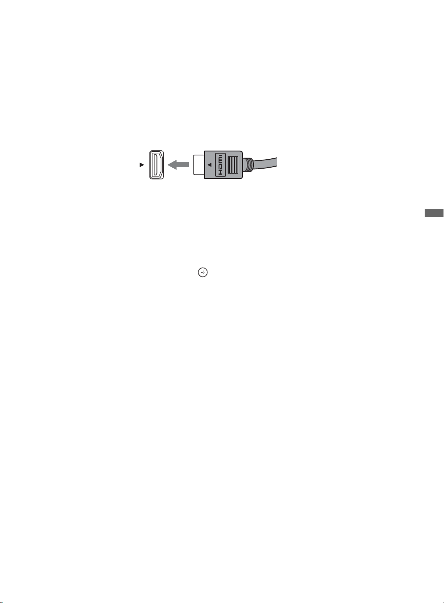
BRAVIA
The BRAVIA Sync function allows this TV to communicate with other Sony equipment
supporting the Control for HDMI function.
To connect Sony equipment with Control for HDMI
Use an HDMI cable that bears the HDMI logo for connection.
Line up the triangle on the head of the HDMI cable with the triangle on the label of the HDMI
input when connecting the HDMI cable.
Setting the Control for HDMI
The Control for HDMI function must be set up in order for the TV to communicate with other
Control for HDMI enabled equipment.
To setup the TV’s Control for HDMI:
®
SyncTM with Control for HDMI
1 Select Channels & Inputs on the Settings menu.
2 Highlight HDMI Settings and press .
3 Select Control for HDMI and set it to On.
To verify connected devices, select Device List from the HDMI Settings menu.
For other equipment, refer to its operating instructions.
Exploring the XMB
™
and TV Features
Available options using Control for HDMI
The following operations are available after you connect the supported Sony equipment with
Control for HDMI function to your TV:
• Automatically turn off the connected equipment when you turn off the TV.
• The connected equipment and TV are turned on by One-Touch-Play.
• Possible operations with SYNC MENU buttons, see page 20.
When a Sony A/V receiver with BRAVIA Sync is connected, the following additional operations
are possible:
• Turning on the A/V receiver when the TV is turned on.
• Automatically switching to the audio output of the A/V receiver’s attached speakers.
• Adjusting the volume and muting of the A/V receiver with the TV’s remote control.
43
Page 44

Other Information
How to Care for Your BRAVIA
Safety is very important, please read and follow the safety documentation (Safety Booklet) separately
provided.
Unplug the TV and other connected equipment from the wall outlet
before you begin cleaning your TV.
• Wipe the LCD screen gently with a soft cloth.
• Stubborn stains may be removed with a cloth slightly moistened
with a solution of mild soap and warm water.
• If using a chemically pretreated cloth, please follow the instruction
provided on the package.
• Never use strong solvents such as a thinner, alcohol or benzine for cleaning.
• Do not plug in the TV into the wall outlet until the moisture from cleaning has evaporated.
The TV should also be placed on a stable surface to prevent it from toppling over (see page 16 and 17). If you
have young children or pets at home, check regularly to insure the TV is securely fastened.
Troubleshooting
Many problems with picture and sound quality are related to improper cable connection; refer to the Quick
Setup Guide provided for sample connections.
Things to consider
• Check the Input selection by pressing INPUT. You may be watching the wrong input.
• You may have accidentally pressed the MUTING button on your remote control; press MUTING again or
press VOL + to deactivate muting.
• The remote control may be installed incorrectly or may be low.
• An object or fluorescent light may be interfering with the remote control’s operation.
• To reset the TV to factory default settings:
1 Turn on the TV.
2 While pressing V on the Remote Control, press POWER on the TV. (The TV will turn itself off, then
back on again.)
WARNING: The reset will clear all of your customized settings including the Parental Lock setting.
If you have forgotten your password, enter the master password: 4357. This password clears your previous
password and allows you to enter a new password.
The online Reference Book provides additional information on troubleshooting. Contact Sony if you
need further assistance.
44
Page 45

Declaration of Conformity
Trade Name: SONY
Model: KDL-40XBR9/KDL-46XBR9/KDL-52XBR9
Responsible Party: Sony Electronics Inc.
Address: 16530 Via Esprillo,
San Diego, CA 92127 U.S.A.
Telephone Number: 858-942-2230
This device complies with part 15 of the FCC rules.
Operation is subject to the following two conditions:
(1) This device may not cause harmful interference, and
(2) this device must accept any interference received,
including interference that may cause undesired
operation.
For customers in Canada
This Class B digital apparatus complies with Canadian
ICES-003.
FCC Related Information
This equipment has been tested and found to comply with
the limits for a Class B digital device, pursuant to Part 15
of the FCC Rules. These limits are designed to provide
reasonable protection against harmful interference in a
residential installation. This equipment generates, uses and
can radiate radio frequency energy and, if not installed and
used in accordance with the instructions, may cause
harmful interference to radio communications. However,
there is no guarantee that interference will not occur in a
particular installation. If this equipment does cause
harmful interference to radio or television reception, which
can be determined by turning the equipment off and on, the
user is encouraged to try to correct the interference by one
or more of the following measures:
❑ Reorient or relocate the receiving antenna.
❑ Increase the separation between the equipment and
receiver.
❑ Connect the equipment into an outlet on a circuit
different from that to which the receiver is connected.
❑ Consult the dealer or an experienced radio/TV
technician for help.
Pursuant to FCC regulations, you are cautioned that any
changes or modifications not expressly approved in this
manual could void your authority to operate this
equipment.
Note
This television includes a QAM demodulator which should
allow you to receive unscrambled digital cable television
programming via subscription service to a cable service
provider. Availability of digital cable television
programming in your area depends on the type of
programming and signal provided by your cable service
provider.
Compatible Wall-Mount Bracket and
Speaker Bar Information
Use the following Sony Wall-Mount Bracket or
Speaker Bar with your TV model.
Sony TV Model No.
KDL-
40XBR9
Sony Wall-Mount
Bracket Model No.
Sony Speaker Bar
Model No.
Use with other Wall-Mount Brackets may cause instability
and could result in property damages or injury.
46XBR9
SU-WL500
HT-CT500
KDL-
KDL-
52XBR9
–
To Customers
Sufficient expertise is required for TV installations. Be
sure to subcontract the installation to a Sony dealer or
licensed contractor and pay adequate attention to safety
during the installation.
For Customers in the United States
The lamp in this product contains mercury.
Disposal of these materials may be regulated
due to environmental considerations. For
disposal or recycling information, please
contact your local authorities or the Electronic
Industries Alliance (www.eiae.org).
Other Information
45
Page 46

Specifications
Model KDL-40XBR9 KDL-46XBR9 KDL-52XBR9
System
Television system NTSC: American TV standard
Channel coverage Analog terrestrial: 2 - 69 / Digital terrestrial: 2 - 69
Panel system LCD (Liquid Crystal Display) Panel
Speaker output 10 W + 10 W
ATSC (8VSB terrestrial): ATSC compliant 8VSB
QAM on cable: ANSI/SCTE 07 2000 (Does not include CableCARD functionality)
Analog Cable: 1 - 135 / Digital Cable: 1 - 135
Input/Output jacks
CABLE/ANTENNA 75-ohm external terminal for RF inputs
VIDEO IN 1/2 S VIDEO (4-pin mini DIN) (VIDEO 2 only): Y: 1.0 Vp-p, 75 ohms unbalanced, sync negative /
COMPONENT IN 1/2
HDMI IN 1/2/3/4
AUDIO OUT 500 mVrms (typical)
DIGITAL AUDIO OUT
(OPTICAL)
PC IN D-sub 15-pin, analog RGB, 0.7 Vp-p, 75 ohms, positive
PC AUDIO INPUT Stereo mini jack, 500 mVrms, (Typical) / Impedance: 47 kilohms
USB MPEG2, MP3, and JPEG.
DLNA MPEG2, LPCM, MP3, and JPEG.
C: 0.286 Vp-p (Burst signal), 75 ohms
VIDEO: 1 Vp-p, 75 ohms unbalanced, sync negative
AUDIO: 500 mVrms (Typical) / Impedance: 47 kilohms
YPBPR (Component Video): Y: 1.0 Vp-p, 75 ohms unbalanced, sync negative / PB: 0.7 Vp-p, 75 ohms /
PR: 0.7 Vp-p, 75 ohms / Signal format: 480i, 480p, 720p, 1080i, 1080p
AUDIO: 500 mVrms (Typical) / Impedance: 47 kilohms
HDMI: Video: 480i, 480p, 720p, 1080i, 1080p, 1080/24p
Audio: Two channel linear PCM 32, 44.1 and 48 kHz, 16, 20 and 24bits, Dolby Digital
AUDIO (HDMI IN 1 only): 500 mVrms (Typical) / Impedance: 47 kilohms
PCM/Dolby Digital optical signal
See the PC Input Signal Reference Chart on page 12.
Power and others
Power requirement 120-240 V AC, 50/60 Hz
Power consumption
in use
in DAM* All models less than 20 W (You may hear a clicking noise during the download but this is normal.)
in standby All models less than 0.1 W with 120 V AC and with 240 V AC less than 0.3 W
Screen size
(inches measured diagonally)
Display resolution 1,920 dots (horizontal) × 1,080 lines (vertical)
Speaker/Full range (2) (mm)
with speaker box (inches)
Tweeter (2) (mm)
Dimensions with stand (mm)
without stand (mm)
wall-mount hole pattern (mm)
wall-mount screw size (mm)
Mass with stand (kg)
Supplied accessories Remote control RM-YD029 (1) / AC power cord (1) / Size AA batteries (2) / Cable clamper
Optional accessories Connecting cables / Support Belt Kit / Wall-Mount Bracket: see page 45
* Download Acquisition Mode (DAM) is used for software updates and/or collecting data for TV Guide On Screen.
~
• Optional accessories availability depends on its stock.
• Design and specifications are subject to change without notice.
(inches)
(inches)
(inches)
without stand (kg)
(lb.)
(lb.)
(1 attached to the Table-Top Stand) / Operating Instruction Manual (1) / Quick Setup Guide (1) /
Warranty Card (1) / Safety and Regulatory Booklet (1) / Attaching the Table-Top Stand (1) /
Screws (4) (except KDL-52XBR9)
205 W 240 W 300 W
40 46 52
×
120
45
3
/4
×
4 3/4
1
16
5
/
8
1,094
×
725
×
×
28 5/8
×
657
×
25 7/8
300 × 300
M6
23.9
52.7
20.6
45.4
330
×
13
×
85
×
3 3/8
1
/8
43
1,094
1
43
/8
(length: refer to diagram on page 7)
37
37
961
961
×
649
×
7
7
/8
303
/8
×
25 5/8
×
580
22 7/8
19.9
43.9
17.2
37.9
12
×
85
×
3 3/8
×
×
1,243
49
1,243
49
×
×
×
821
×
32 3/8
×
14 1/8
×
745
×
29 3/8 × 3 3/8
29.9
65.9
25.9
57.1
358
85
46
Page 47

Index
0-9 buttons 21
A
AUDIO OUT jack, described 8, 9
Auto Program 18
B
Background TV 40
BD/DVD MENU button 21
BD/DVD TOP MENU button 21
BRAVIA INTERNET VIDEO button 21
BRAVIA INTERNET WIDGETS button 22
BRAVIA Sync buttons 20
C
CABLE/ANTENNA input, described 8, 9
CC button 22
CH +/– button 22, 23
COMPONENT IN (1080p/1080i/720p/480p/480i) 8, 9
D
DIGITAL AUDIO OUT (OPTICAL) 8, 9
DISPLAY button 20
DMex/SERVICE 8, 9
DVR/VCR Record Buttons 21
E
ENT button 21
F
F1/F2 buttons 22
Favorites 37
FAVORITES button 21
FUNCTION button 20
G
GUIDE button 21
H
HD SIGNAL 23
HDMI IN 1/2/3/4 L-AUDIO-R 8, 9
HOME button 21, 23
I
Infrared Receiver (IR) 23
INPUT button 22, 23
J
JUMP button 22
L
LAN 8, 9
LIGHT button 20
Light Sensor 23
M
MUTING button 21
O
OPTIONS button 22
P
PC IN 8, 9
PIC OFF/TIMER LED 23
POWER button 21, 23
POWER/STANDBY LED 23
Programming the Remote Control 24
R
RETURN button 21
S
S VIDEO jack 8, 9
SCENE button 21
Speaker 23
T
Troubleshooting 44
U
USB 8, 9
V
VIDEO/AUDIO (L/R) jacks, described 8, 9
VOL +/– button 21, 23
W
WIDE button 21
Y
YELLOW, BLUE, RED, GREEN buttons 21
Other Information
47
Page 48

Online
Reference
Book:
For Your Convenience
To learn more about your TV, visit the
online Reference Book at:
http://www.sony.com/referencebook
Online
Registration:
Software
Updates:
Be sure to register your TV.
United States
Canada
Your TV is capable of receiving software updates. For the
latest information about software updates for your TV, visit:
United States
Canada
NOTE: If your TV is connected to the Internet, you can check
for software updates by selecting Settings, Product
Support and then Software Update.
http://productregistration.sony.com
http://www.SonyStyle.ca/registration
http://www.sony.com/tvsupport
http://www.sony.ca/support
Printed in U.S.A.
4-140-826-11(1)
 Loading...