

Sony KDL-40XBR45,KDL-46XBR45,KDL-40X4500,KDL-55XBR45,KDL-46X4500,KDL-55X4500 Service Manual
Ver. DATA CONTENTS
1.0 2008.08 Issued
1.1 2008.09 • Addition of 46 inch and 55 inch of the Australian model.
•Addition of New Zealand and Singapore models.
•Addition of TROUBLE SHOOTING.
(P. 1, P. 2, P. 3, P. 9, P. 2 5 , P. 2 6 , P. 2 7 , P. 28 , P. 29, P. 3 0 , P. 3 1 )
1.2 2008.10 Reformed completely
MODEL NAME : KDL-40/46/55XBR45, 40/46/55X4500
SERVICE MANUAL
PA RTS No. : 9-888-221-03
MODIFICATION HISTORY
* Blue characters are linking.
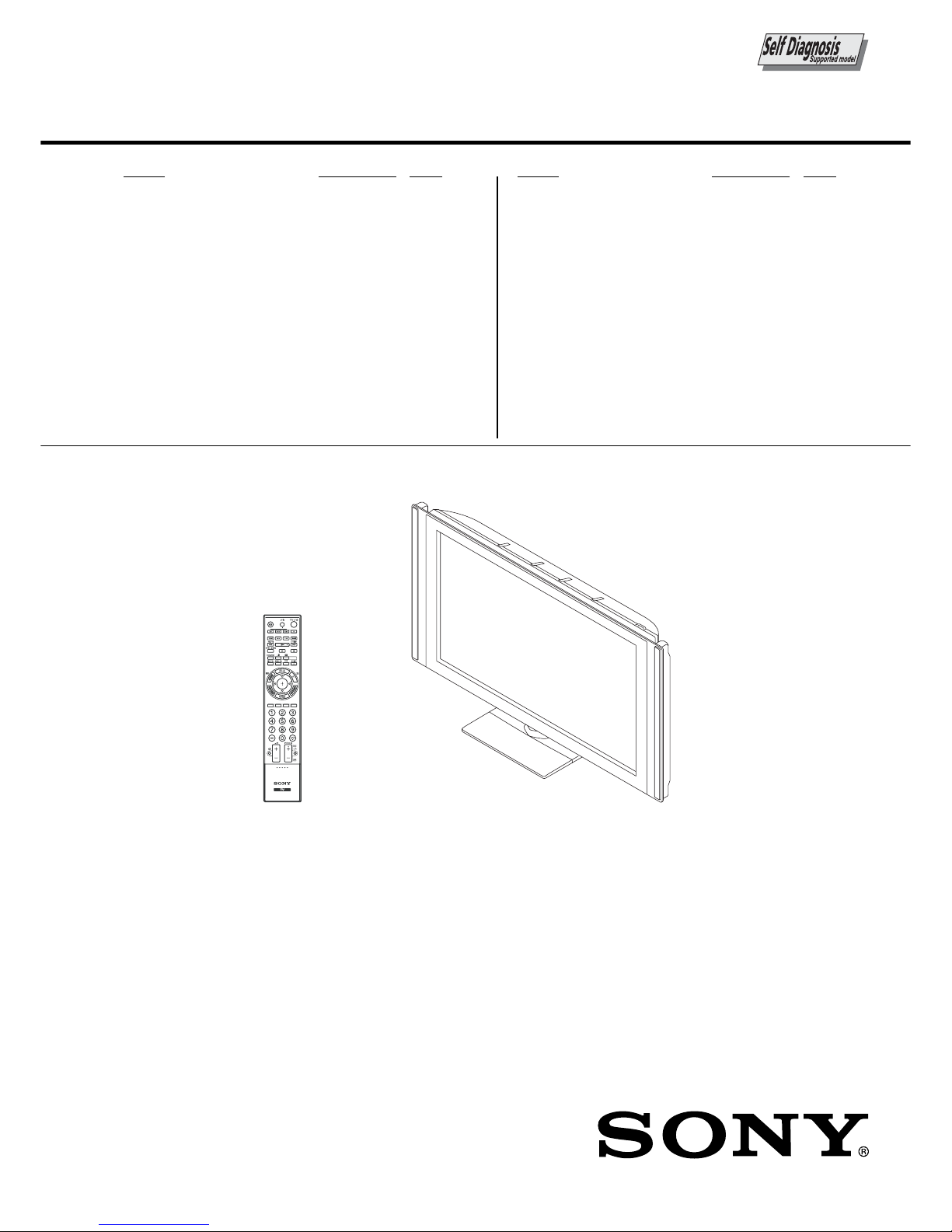
SERVICE MANUAL
EG1H
CHASSIS
LCD Digital Colour TV
RMF-GD001 KDL-40XBR45/46XBR45/55XBR45
KDL-40X4500
/46X4500/55X4500
MODEL
KDL-40XBR45
KDL-46XBR45
KDL-55XBR45
KDL-40X4500
KDL-46X4500
KDL-55X4500
COMMANDER
RMF-GD001
RMF-GD001
RMF-GD001
RMF-GD001
RMF-GD001
RMF-GD001
DEST.
Australian
Australian
Australian
New Zealand
New Zealand
New Zealand
MODEL
KDL-40X4500
KDL-46X4500
KDL-55X4500
COMMANDER
RMF-GD001
RMF-GD001
RMF-GD001
DEST.
Singapore
Singapore
Singapore
KDL-40/46/55XBR45 (AUS), 40/46/55X4500 (NZ, ES) 2
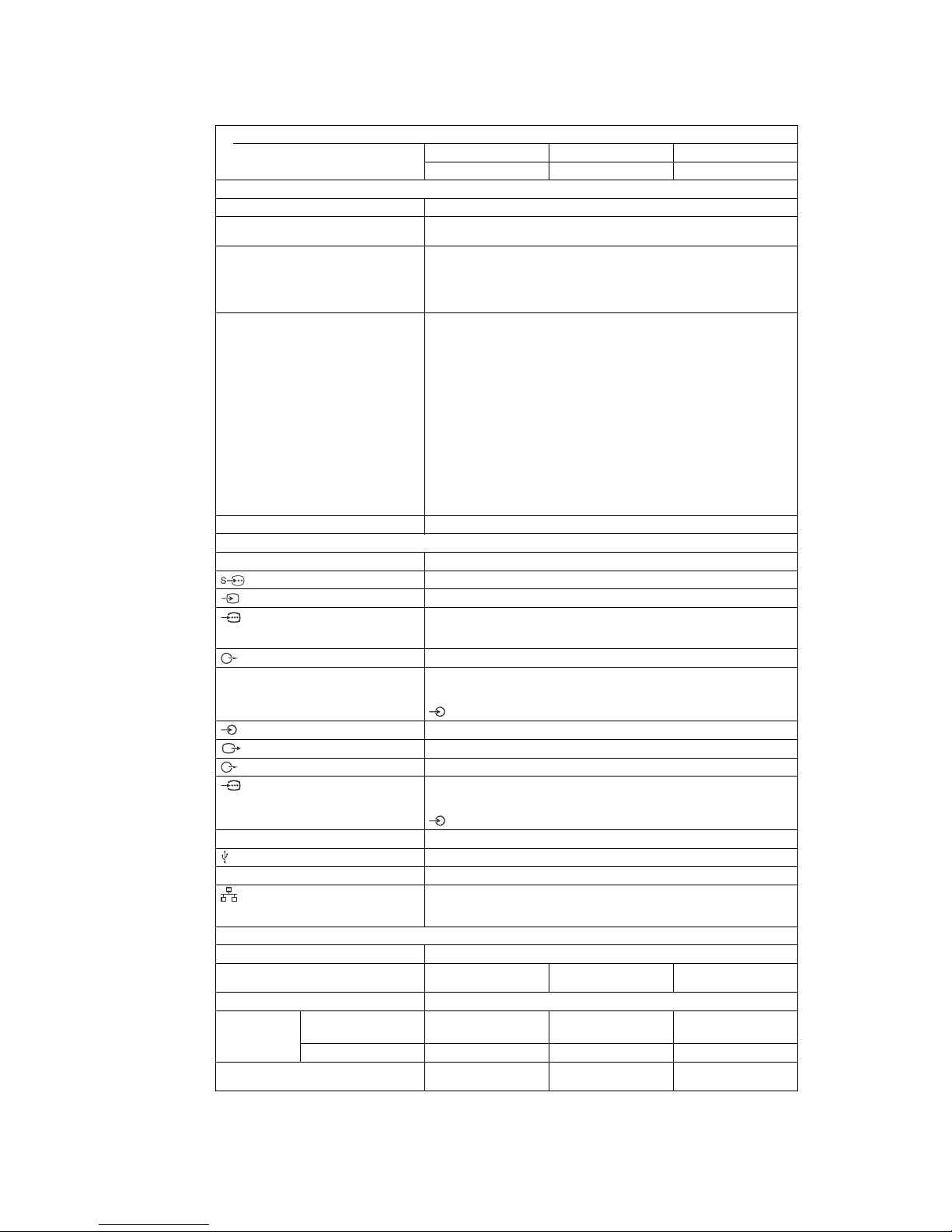
SPECIFICATIONS
Model name
KDL-55XBR45
1
DMPORT
i
LAN
Display resolution
Australian model
New Zealand/Singapore model
System
Panel system
TV system
Colour/video system
Channel coverage
Sound output
Input/Output jacks
Antenna
1, 2, 3
1, 2
1, 2, 3
HDMI IN1, 2, 3, 4
DIGITAL AUDIO OUT (OPTICAL)
PC IN (RGB)
Power and others
Power requirements
Screen size (measured diagonally)
Power
consumption
Standby power consumption*
in “Home”/“Standard”
mode
in “Shop”/“Vivid” mode
KDL-40XBR45
KDL-40X4500
KDL-46XBR45
KDL-46X4500 KDL-55X4500
LCD (Liquid Crystal Display) Panel
Analogue: B/G, I, D/K
Digital: DVB-T
Analogue: PAL, PAL60 (only video input), SECAM, NTSC3.58,
NTSC4.43 (only video input)
Digital: MPEG-2 MP@ML/HL (Australian model),
MPEG-2 MP@ML/HL, H.264/MPEG-4 AVC MP/HP@L4
(New Zealand/Singapore model)
Analogue: B/G:VHF: E2 to E12 / UHF: E21 to E69 /CATV: S01 to S03, S1 to S41
VHF: 0 to 12, 5A, 9A / UHF: 28 to 69 /CATV: S01 to S03, S1 to S44
(Australia only)
VHF: 1 to 11 / UHF: 21 to 69 /CATV: S01 to S03, S1 to S41
(New Zealand only)
I: UHF: B21 to B69 / CATV: S01 to S03, S1 to S41
D/K: VHF: C1 to C12, R1 to R12 /UHF: C13 to C57, R21 to R60
(Australian/New Zealand only)
VHF: R1 to R12 /UHF: R21 to R69 (Singapore only)
CATV: S01 to S03, S1 to S41, Z1 to Z39
(Australian/New Zealand only)
CATV: S01 to S03, S1 to S41 (Singapore only)
Digital: VHF/UHF (Australian/ Singapore models), UHF (New Zealand model)
10 W + 10 W, 12 W + 12 W (Woofer)
75 ohm external terminal for VHF/UHF
S video input (4-pin mini DIN)
Video input (phono jacks)
Supported formats: 1080p, 1080i, 720p, 576p, 576i, 480p, 480i
Y: 1 Vp-p, 75 ohms, 0.3V negative sync/P
B/CB
: 0.7 Vp-p, 75 ohms/
P
R/CR
: 0.7 Vp-p, 75 ohms
Audio input (phono jacks)
Video: 1080/24p, 1080p, 1080i, 720p, 576p, 576i, 480p, 480i
Audio: Two channel linear PCM: 32, 44.1 and 48 kHz, 16, 20 and 24 bits
Analogue audio input (minijack) (HDMI IN 1 only)
PC Input
Digital optical jack
Video output (phono jack)
Audio output (phono jacks)
PC Input (D-sub 15-pin)
G: 0.7 Vp-p, 75 ohms, non Sync on Green/B: 0.7 Vp-p, 75 ohms/
R: 0.7 Vp-p, 75 ohms/HD: 1-5 Vp-p/VD: 1-5 Vp-p
PC audio input (minijack)
DIGITAL MEDIA PORT
USB port
Headphones jack
10BASE-T/100BASE-TX connector (Depending on the operating environment
of the network, connection speed may differ. 10BASE-T/100BASE-TX
communication rate and communication quality are not guaranteed for this TV.)
220 V – 240 V AC, 50 Hz
40 inches 46 inches 55 inches
(Approx. 101.6 cm) (Approx. 116.8 cm) (Approx. 138.8 cm)
1,920 dots (horizontal) × 1,080 lines (vertical)
210 W 270 W 370 W
230 W 350 W 480 W
0.3 W (19 W when “Quick 0.6 W (20 W when “Quick 0.7 W (22 W when “Quick
Start” is set to “On”) Start” is set to “On”) Start” is set to “On”)
KDL-40/46/55XBR45 (AUS), 40/46/55X4500 (NZ, ES) 3
Resolution
zontal Horizontal
(Pixel)
×
×
×
×
×
×
×
×
×
×
×
×
×
×
×
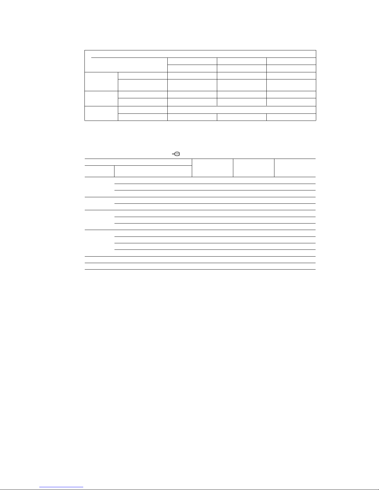
Model name
KDL-46X4500
Australian model
New Zealand/Singapore model
Dimensions
(Approx.)
(w × h × d)
Mass (Approx.)
Optional
accessories
with Table-Top Stand
without Table-Top Stand
with Table-Top Stand
without Table-Top Stand
Wall-Mount Bracket
Colour Variation Unit
KDL-40XBR45
KDL-40X4500
KDL-46XBR45 KDL-55XBR45
KDL-55X4500
* Specified standby power is reached after the TV finishes necessary internal processes.
Design and specifications are subject to change without notice.
PC input signal reference chart for PC and HDMI IN 1, 2, 3, 4
Signals Vertical
(Line)
Horizontal
frequency (kHz)
Ver tical
frequency (Hz)
Standard
* 1080p timing when applied to the HDMI input will be treated as a video timing and not a PC timing. This
affects the “Video Settings” menu and “Screen” menu settings.
To view PC contents, set “Game/Text Mode” to “On”, “Wide Mode” to “Full”, and “Display Area”h to “Full
Pixel”.
• This TV’s PC input does not support Sync on Green or Composite Sync.
• This TV’s PC input does not support interlaced signals.
• For the best picture quality, it is recommended to use the signals in the above chart with a 60 Hz vertical
frequency (boldfaced).
1,128 × 655 × 279 mm 1,259 × 737 × 315 mm 1,486 × 855 × 356 mm
1,128 × 603 × 125 mm 1,259 × 685 × 144 mm 1,486 × 803 × 147 mm
27.0 kg 38.0 kg 54.0 kg
23.5 kg 33.0 kg 47.5 kg
SU-WL500/WL50B
CRU-40SG11 CRU-46SG11 CRU-55SG11
VGA 640 480 31.5 60 VGA
640 480 37.5 75 VESA
720 400 31.5 70 VGA-T
SVGA 800 600 37.9 60 VESA Guidelines
800 600 46.9 75 VESA
XGA 1024 768 48.4 60 VESA Guidelines
1024 768 56.5 70 VESA
1024 768 60.0 75 VESA
WXGA 1280 768 47.4 60 VESA
1280 768 47.8 60 VESA
1280 768 60.3 75
1360 768 47.7 60 VESA
SXGA 1280 1024 64.0 60 VESA
HDTV 1920 1080 67.5 60 CEA-861*

KDL-40/46/55XBR45 (AUS), 40/46/55X4500 (NZ, ES) 4
CAUTION
These servicing instructions are for use by qualified service
personnel only.
To reduce the risk of electric shock, do not perform any servicing
other than that contained in the operating instructions unless you
are qualified to do so.
WARNING!!
An isolation transformer should be used during any service to
avoid possible shock hazard, because of live chassis.
The chassis of this receiver is directly connected to the ac power
line.
! SAFETY-RELATED COMPONENT
WARNING!!
Replace all components with Sony parts whose part numbers
appear as shown in this manual or in supplements
published by Sony.
WARNINGS AND CAUTIONS SAFETY-RELATED COMPONENT
WARNING
It is essential that all critical parts be replaced only with the part
number specified in the electrical parts list to prevent electric
shock, fire, or other hazard.
NOTE: Do not modify the original design without obtaining
written permission from the manufacturer or you will
void the original parts and labor guarantee.
USE CAUTION WHEN HANDLING THE LCD PANEL
When repairing the LCD panel, be sure you are grounded by
using a wrist band.
When repairing the LCD panel on the wall, the LCD panel must
be secured using the 4 mounting holes on the rear cover.
1) Do not press on the panel or frame edge to avoid the risk of
electric shock.
2) Do not scratch or press on the panel with any sharp objects.
3) Do not leave the module in high temperatures or in areas of
high humidity for an extended period of time.
4) Do not expose the LCD panel to direct sunlight.
5) Avoid contact with water. It may cause a short circuit within
the module.
6) Disconnect the AC power when replacing the backlight (CCFL)
or inverter circuit.
(High voltage occurs at the inverter circuit at 650Vrms.)
7) Always clean the LCD panel with a soft cloth material.
8) Use care when handling the wires or connectors of the inverter
circuit. Damaging the wires may cause a short.
9) Protect the panel from ESD to avoid damaging the electronic
circuit (C-MOS).
KDL-40/46/55XBR45 (AUS), 40/46/55X4500 (NZ, ES) 5
SAFETY CHECK-OUT
After correcting the original service problem, perform the
following safety checks before releasing the set to the customer:
1. Check the area of your repair for unsoldered or poorly
soldered connections. Check the entire board surface for
solder splashes and bridges.
2. Check the interboard wiring to ensure that no wires are
“pinched” or touching high-wattage resistors.
3. Check that all control knobs, shields, covers, ground straps,
and mounting hardware have been replaced. Be absolutely
certain that you have replaced all the insulators.
4. Look for unauthorized replacement parts, particularly
transistors, that were installed during a previous repair. Point
them out to the customer and recommend their replacement.
5. Look for parts which, though functioning, show obvious
signs of deterioration. Point them out to the customer and
recommend their replacement.
6. Check the line cords for cracks and abrasion. Recommend
the replacement of any such line cord to the customer.
7. Check the antenna terminals, metal trim, “metallized”
knobs, screws, and all other exposed metal parts for AC
leakage. Check leakage as described below.
Leakage Test
The AC leakage from any exposed metal part to earth ground
and from all exposed metal parts to any exposed metal part
having a return to chassis, must not exceed 0.5 mA (500
microamperes).
Leakage current can be measured by any one of three methods.
1. A commercial leakage tester, such as the Simpson 229 or
RCA WT-540A. Follow the manufacturers’ instructions to
use these instructions.
2. A battery-operated AC milliampmeter. The Data Precision
245 digital multimeter is suitable for this job.
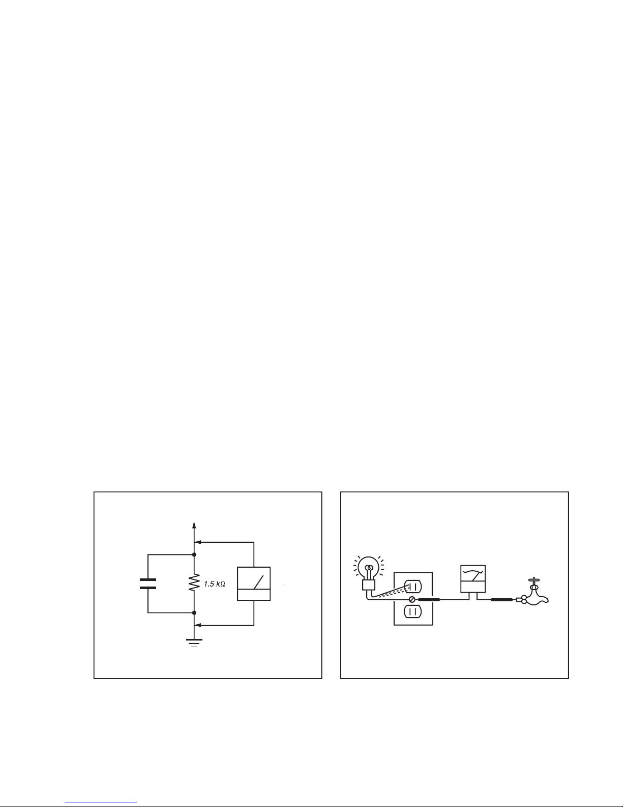
3. Measuring the voltage drop across a resistor by means of a
VOM or battery-operated AC voltmeter. The “limit”
indication is 0.75 V, so analog meters must have an accurate
low voltage scale.
The Simpson’s 250 and Sanwa SH-63TRD are examples of
passive VOMs that are suitable. Nearly all battery-operated
digital multimeters that have a 2 VAC range are suitable (see
Figure A).
How to Find a Good Earth Ground
A cold-water pipe is a guaranteed earth ground; the cover-plate
retaining screw on most AC outlet boxes is also at earth ground.
If the retaining screw is to be used as your earth ground, verify
that it is at ground by measuring the resistance between it and a
cold-water pipe with an ohmmeter. The reading should be zero
ohms.
If a cold-water pipe is not accessible, connect a 60- to 100-watt
trouble- light (not a neon lamp) between the hot side of the
receptacle and the retaining screw. Try both slots, if necessary,
to locate the hot side on the line; the lamp should light at normal
brilliance if the screw is at ground potential (see Figure B).
Exposed Meta
l
Parts on Se
t
.15
µ
Earth Groun
d
AC
0.75V
)
ouble Ligh
t
AC Outlet Box
Ohmmeter
Col
d-water Pi
pe
FigureA. Using an AC voltmeter to check AC leakage. Figure B. Checking for earth ground
.
KDL-40/46/55XBR45 (AUS), 40/46/55X4500 (NZ, ES) 6
SELF DIAGNOSIS FUNCTION
The units in this manual contain a self-diagnostic function. If an error occurs, the STANDBY LED will automatically begin to flash.
The number of times the LED flashes translates to a probable source of the problem.
A definition of the STANDBY LED flash indicators is listed in the instruction manual for the user’s knowledge and reference.
If an error symptom cannot be reproduced, the remote commander can be used to review the failure occurrence data stored in memory to
reveal past problems and how often these problems occur.
DIAGNOSTIC TEST INDICATORS
When an error occurs, the STANDBY LED will flash a set number of times to indicate the possible cause of the problem.
If there is more than one error, the LED will identify the first of the problem areas.
Result for all of the following diagnostic items are displayed on screen.
If the screen displays a “0”, no error has occurred .
Number of times STANDBY Monitoring Items
Detection
LED (Red) flashes (Screen Display)
2 times POW_ERR1 AAS Board IC2104
79pin: i_lb_err (AD port) < PW_ERR_LEV (Threshold Value)
and
138pin: i_ac_off_det: HIGH
5 times T_CON FBA Board IC
5501
1128Pin: TCON_RDY: Low
or
2Detected Error of Cayenne Register
6 times BACKLITE FBA Board IC5501
78Pin: INV_FAIL: LOW
7 times PANLTEMP FBA Board IC5501
IIC_ch2 setting value (BEM data)
8 times AUD_PROT AAS Board IC2104
19pin: i_au_prot: Low
9 times FAN_ERR FBA Board IC5501
pin154: FAN_ERR: High
13 times BALANCER FBA Board IC5501
1163pin: BALANCER_ERR: LOW
or
2SPI_ERR_CNT (SetSREG) >= SPI_ERR_LIM (FactSREG)
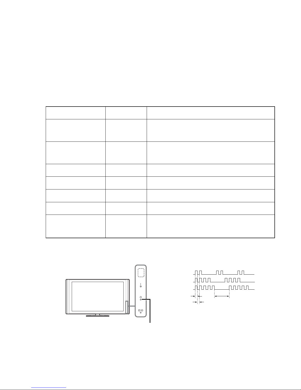
DISPLAY OF STANDBY LIGHT FLASH COUNT
STOPPING THE STANDBY FLASH
Turn off the power switch on the TV main unit or unplug the power cord from the outlet to stop the STANDBY LED for flashing.
2 times
4 times
5 times
LED ON 0.3 sec.
LED OFF 0.3 sec.
LED OFF
2 sec.
[ FLASH COUNT ]
Note: One flash counts is not self-diagnostic.
STANDBY LED
KDL-40/46/55XBR45 (AUS), 40/46/55X4500 (NZ, ES) 7
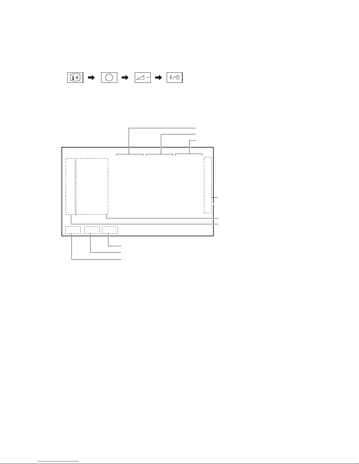
SELF-DIAGNOSTIC SCREEN DISPLAY
For errors with symptoms such as “power sometimes shuts off” or “screen sometimes goes out” that cannot be confirmed, it is possible to
bring up past occurrences of failure for confirmation on the screen:
[To Bring Up Screen Test]
In standby mode, press buttons on the remote commander sequentially in rapid succession as shown below:
Since the diagnostic results displayed on the screen are not automatically cleared, always check the self-diagnostic screen
After you have completed the repairs, clear the result display to “0”.
Clearing the result display
To clear the result display to “0”, press button on the remote commander sequentially as shown below when the diagnostic screen is being
displayed.
<Delection of Error Count and Error History>
Press “8” button , Press “-” button
<Delection of Panel Operation Time>
Press “7” button , Press “-” button
Quitting Self-diagnostic screen
To quit the entire self-diagnostic screen, turn off the power switch on the remote commander or the main unit.
5
* : Note that this differs from entering the service mode (volume +)
( Number button )
* ( Volume ) ( TV standby )
( Info/Text reveal )
002 POW_ERR1
005 T_CON
006 BACKLITE
007 PANL TEMP
008 AUD_PROT
009 FAN_ERR
013 BALANCER
SELF CHECK
12345 - 00333 - 06789
0501210811 0412311234 0311111825 00
0000000000 0000000000 0000000000 00
0000000000 0000000000 0000000000 00
0000000000 0000000000 0000000000 00
0000000000 0000000000 0000000000 00
0000000000 0000000000 0000000000 00
0000000000 0000000000 0000000000 00
Item name
The last failure time
Falure time before last
Last failure time beforehand
Error count (00-99)
Frequency of LED blinking.
Total operation time by hour (max 99999)
Boot count (max 99999)
Panel operation time by hour (max 99999)
[ SELF-DIAGNOSTIC SCREEN DISPLAY ]

KDL-40/46/55XBR45 (AUS), 40/46/55X4500 (NZ, ES) 8
TABLE OF CONTENTS
SPECIFICATIONS .................................................... 2
SAFETY CHECK-OUT ............................................. 5
SELF DIAGNOSIS FUNCTION ................................ 6
TABLE OF CONTENTS ........................................... 8
1. DISASSEMBLY ...............................................1-1
1-1. KDL-40XBR45/40X4500 ...................................... 1-1
1-1-1. REAR COVER REMOVAL............................ 1-1
1-1-2. STAND ASSY REMOVAL ............................ 1-1
1-1-3. H1VM BOARD REMOVAL .......................... 1-2
1-1-4. HEAT SINK REMOVAL ................................ 1-2
1-1-5. SP BOX ASSY (WOOFER) REMOVAL ....... 1-3
1-1-6. UNDER COVER, SIDE JACK BRACKET
AND CARD BRACKET REMOVAL ............ 1-3
1-1-7. D4 BOARD REMOVAL ................................. 1-4
1-1-8. G6 BOARD REMOVAL ................................. 1-4
1-1-9. K2 BOARD REMOVAL ................................. 1-5
1-1-10. FB SHIELD REMOVAL ................................. 1-5
1-1-11. AAS AND FBA BOARDS REMOVAL ......... 1-6
1-1-12. AC INLET REMOVAL ................................... 1-6
1-1-13. SPINE FRAME REMOVAL ........................... 1-7
1-1-14. SPEAKER BOX ASSY REMOVAL .............. 1-7
1-1-15. LCD PANEL, H3VM BOARD AND
H4 BOARD REMOVAL ................................. 1-8
1-2. KDL-46XBR45/46X4500 ...................................... 1-9
1-2-1. REAR COVER REMOVAL............................ 1-9
1-2-2. STAND ASSY REMOVAL ............................ 1-9
1-2-3. H1VM BOARD REMOVAL ........................ 1-10
1-2-4. PANEL FIN REMOVAL .............................. 1-10
1-2-5. FAN REMOVAL ........................................... 1-11
1-2-6. CB1 BOARD REMOVAL ............................ 1-11
1-2-7. SP BOX (WOOFER) REMOVAL ................ 1-12
1-2-8. UNDER COVER, SIDE JACK BRACKET
AND CARD BRACKET REMOVAL .......... 1-12
1-2-9. G6 BOARD REMOVAL ............................... 1-13
1-2-10. GL BOARD REMOVAL ............................... 1-13
1-2-11. K2 BOARD REMOVAL ............................... 1-14
1-2-12. FB SHIELD REMOVAL ............................... 1-14
1-2-13. AAS AND FBA BOARDS REMOVAL ....... 1-15
1-2-14. AC INLET REMOVAL ................................. 1-15
1-2-15. SPEAKER BOX ASSY REMOVAL ............ 1-16
1-2-16. LCD PANEL, H3VM BOARD AND
H4 BOARD REMOVAL ............................... 1-16
1-3. KDL-55XBR45/55X4500 .................................... 1-17
1-3-1. REAR COVER REMOVAL.......................... 1-17
1-3-2. STAND ASSY REMOVAL .......................... 1-17
1-3-3. H1VM BOARD REMOVAL ........................ 1-18
1-3-4. PANEL FIN REMOVAL .............................. 1-18
1-3-5. FAN REMOVAL ........................................... 1-19
1-3-6. CB1 BOARD REMOVAL ............................ 1-19
1-3-7. SP BOX (WOOFER) ASSY REMOVAL ..... 1-20
1-3-8. UNDER COVER, SIDE JACK BRACKET
AND CARD BRACKET REMOVAL .......... 1-20
1-3-9. G6 BOARD REMOVAL ............................... 1-21
1-3-10. G7 BOARD REMOVAL ............................... 1-21
1-3-11. GL BOARD REMOVAL ............................... 1-22
1-3-12. K2 BOARD REMOVAL ............................... 1-22
1-3-13. FB SHIELD REMOVAL ............................... 1-23
1-3-14. AAS AND FBA BOARDS REMOVAL ....... 1-23
1-3-15. AC INLET REMOVAL ................................. 1-24
1-3-16. SPEAKER BOX ASSY REMOVAL ............ 1-24
1-3-17. LC PANEL, H3VM BOARD AND
H4 BOARD REMOVAL ............................... 1-25
2. TROUBLESHOOTING .................................... 2-1
2-1. TRIAGE CHART ................................................... 2-1
2-2. FLOW CHART ...................................................... 2-2
3. DIAGRAMS ..................................................... 3-1
3-1. BLOCK DIAGRAM .............................................. 3-1
3-2. CIRCUIT BOARDS LOCATION ......................... 3-2
(1) KDL-40XBR45/40X4500 ................................ 3-2
(2) KDL-46XBR45/46X4500 ................................ 3-2
(3) KDL-55XBR45/55X4500 ................................ 3-2
4. EXPLODED VIEWS ........................................ 4-1
4-1. KDL-40XBR45/40X4500 ...................................... 4-2
4-1-1. REAR COVER AND STAND ASSY ............. 4-2
4-1-2. H1VM BOARD AND UNDER COVER ........ 4-3
4-1-3. D4 AND K2 BOARDS .................................... 4-4
4-1-4. FBA, AAS AND G6 BOARDS ....................... 4-5
4-1-5. AC INLET AND RF MODULE ...................... 4-6
4-1-6. SPEAKER AND GRILLE ............................... 4-7
4-1-7. LCD PANEL .................................................... 4-8
4-1-8. CONNECTOR ASSY ...................................... 4-9
4-2. KDL-46XBR45/46X4500 .................................... 4-10
4-2-1. REAR COVER AND STAND ASSY ........... 4-10
4-2-2. H1VM BOARD AND UNDER COVER ...... 4-11
4-2-3. FAN AND WOOFER SPEAKER ................. 4-12
4-2-4. G6, GL AND K2 BOARDS........................... 4-13
4-2-5. AAS, CB1 AND FBA BOARDS .................. 4-14
4-2-6. SPEAKER AND GRILLE ............................. 4-15
4-2-7. LCD PANEL .................................................. 4-16
4-2-8. CONNECTOR ASSY .................................... 4-17
4-3. KDL-55XBR45/55X4500 .................................... 4-18
4-3-1. REAR COVER AND STAND ASSY ........... 4-18
4-3-2. H1VM BOARD AND UNDER COVER ...... 4-19
4-3-3. FAN AND WOOFER SPEAKER ................. 4-20
4-3-4. G6, G7, GL AND K2 BOARDS ................... 4-21
4-3-5. AAS, CB1 AND FBA BOARDS .................. 4-22
4-3-6. SPEAKER AND GRILLE ............................. 4-23
........................................................................ 4-24
4-3-7. LCD PANEL .................................................. 4-24
4-3-8. CONNECTOR ASSY .................................... 4-25
4-4. PACKING MATERIALS .................................... 4-26
4-4-1. KDL-40XBR45/40X4500 .............................. 4-26
4-4-2. KDL-46XBR45/46X4500 .............................. 4-27
4-4-3. KDL-55XBR45/55X4500 .............................. 4-28
KDL-40/46/55XBR45 (AUS), 40/46/55X4500 (NZ, ES) 1-1
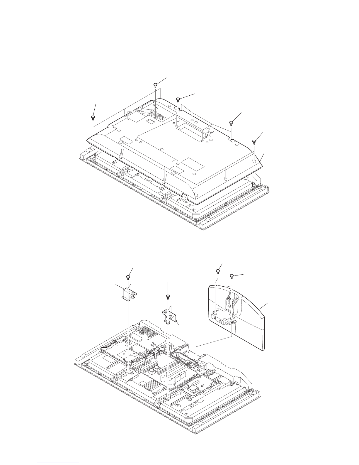
1-1. KDL-40XBR45/40X4500
1-1-1. REAR COVER REMOVAL
SECTION 1
DISASSEMBLY
1-1-2. STAND ASSY REMOVAL
1 Four screws
(+BVTP2 4X16)
3 Two screws
(+BV 3X12)
1 Five screws
(+BVTP2 4X16)
4 RER COVER
1 Six screws
(+BVTP2 4X16)
2 Four screws
(+PSW M5X8)
1 Two screws
(+PSW M5X16)
3 Two screws
(+PSW M5X8)
5 Two screws
(+PSW M5X8)
4 Vesa (TOP) frame
6 Vesa (TOP) frame
1 Two screws
(+PSW M5X16)
2 Stand assy (ML-4)
KDL-40/46/55XBR45 (AUS), 40/46/55X4500 (NZ, ES) 1-2
KDL-40XBR45/40X4500
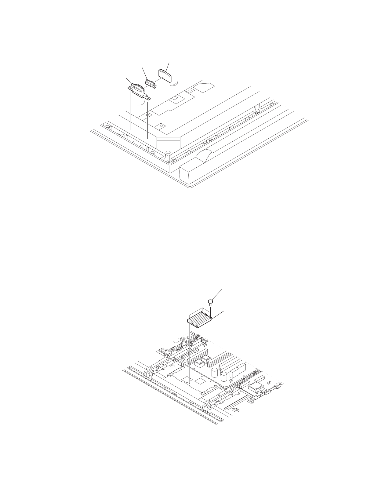
1-1-3. H1VM BOARD REMOVAL
1-1-4. HEAT SINK REMOVAL
1 Power bracket
2 Power button
3 H1VM board
2 Heat sink
1 Three screws
(+PSW 3X8)
KDL-40/46/55XBR45 (AUS), 40/46/55X4500 (NZ, ES) 1-3
KDL-40XBR45/40X4500
1-1-5. SP BOX ASSY (WOOFER) REMOVAL
1-1-6. UNDER COVER, SIDE JACK BRACKET AND CARD BRACKET REMOVAL
1 One screw
(+PWTP2 4X16)
1 One screw
(+PWTP2 4X16)
2 SP box assy
(WOOFER)
3 One screw
(+BVST 3X8)
4 AWF bracket
5 One screw
(+PWTP2 4X16)
5 One screw
(+PWTP2 4X16)
6 SP box assy
(WOOFER)
7 One screw
(+BVST 3X8)
8 AWF bracket
1 Two screws
(+PSW M5X8)
2 Vesa (BTM) frame
3 Two screws
(+PSW M5X8)
4 Vesa (BTM) frame
5 One screw
(+PSW M4X8)
7 Card bracket
8 MS cover
9 Side jack bracket
6 Under cover
KDL-40/46/55XBR45 (AUS), 40/46/55X4500 (NZ, ES) 1-4
KDL-40XBR45/40X4500
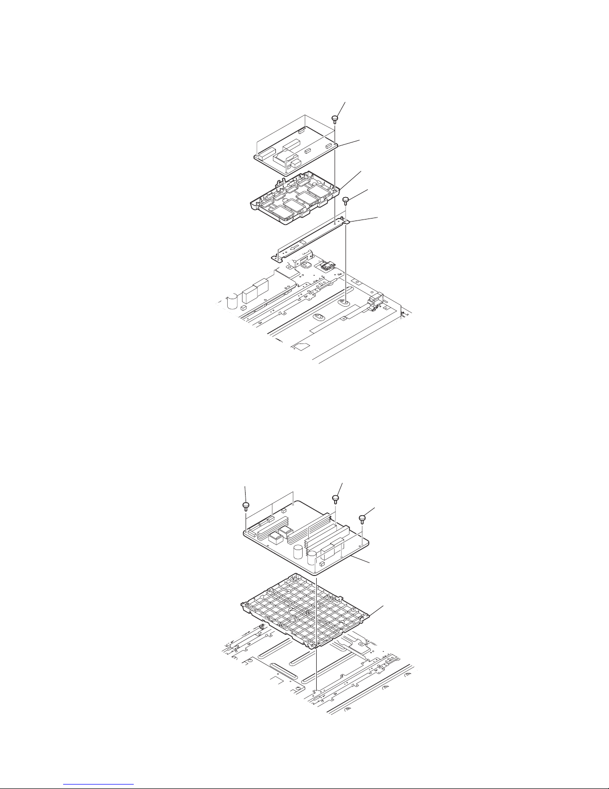
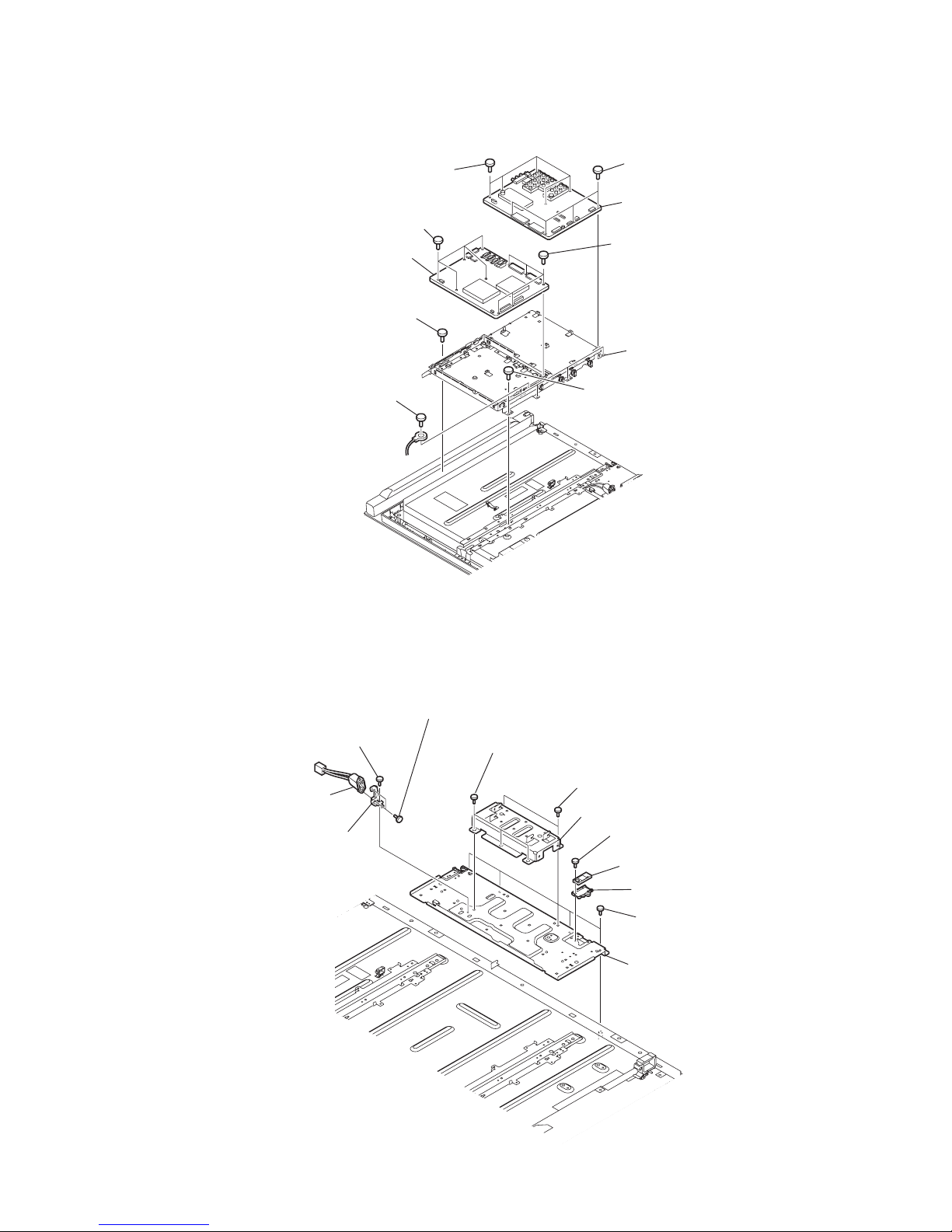
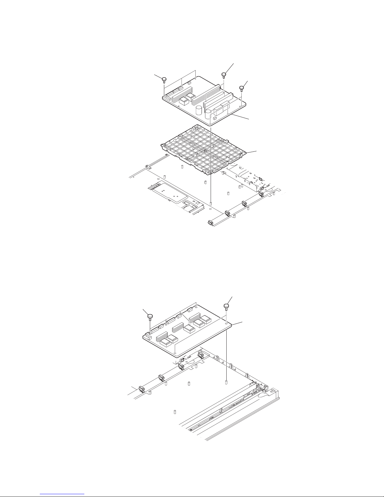
1-1-7. D4 BOARD REMOVAL
1-1-8. G6 BOARD REMOVAL
1 Four screws
(+PSW 3SG)
2 D4 board
4 Two screws
(+PSW M3X5)
3 D4 bracket
5 D4 frame
2 Two screws
( +BV 3X12)
1 Three screws
(+PSW 3X8)
1 Three screws
(+PSW 3X8)
3 G6 board
4 G6 bracket
KDL-40/46/55XBR45 (AUS), 40/46/55X4500 (NZ, ES) 1-5
KDL-40XBR45/40X4500
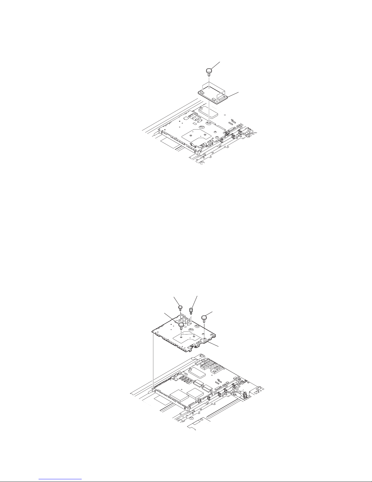
1-1-9. K2 BOARD REMOVAL
1-1-10. FB SHIELD REMOVAL
1 Four screws
(+PSW M3X5)
2 K2 board
1 Two screws
(+PSW 3X8)
2 Three screws
(+PSW M3X5)
3 Two screws
(SP 4-4O UNC)
1 One screw
(+BVST 3X8)
4 FB shield
KDL-40/46/55XBR45 (AUS), 40/46/55X4500 (NZ, ES) 1-6
KDL-40XBR45/40X4500
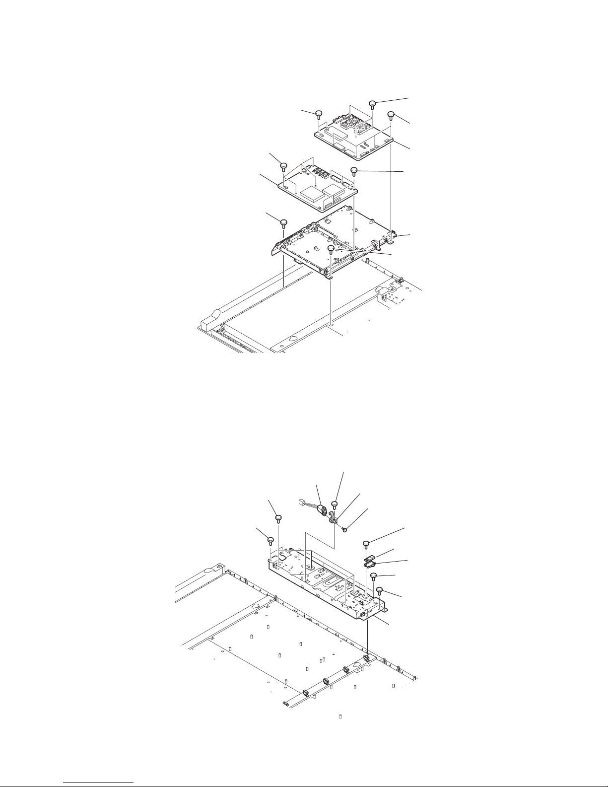
1-1-11. AAS AND FBA BOARDS REMOVAL
1-1-12. AC INLET REMOVAL
1 Five screws
(+BVST 3X8)
1 Four screws
(+BVST 3X8)
2 AAS board
3 Five screws
(+BVST 3X8)
4 FBA board
6 One screw
(+BVTP2 4X16)
7 One screw
(+BVST 3X8)
5 Four screws
(+PSW M3X5)
8 Main bracket
3 Five screws
(+BVST 3X8)
4 AC inlet
1 One screw
(+BVST 3X8)
3 Two screws
(+KTT 3X10 (S TYPE))
5 Three screws
(+PSW M4X8)
6 Stand holder
qa Bottom Frame (40)
9 RF module
8 RF bracket
0 Four screws
(+BVTP2 4X16)
7 One screw
(+PSW M3X5)
2 AC inlet bracket
5 Two screws
(+PSW M4X8)

KDL-40/46/55XBR45 (AUS), 40/46/55X4500 (NZ, ES) 1-7
KDL-40XBR45/40X4500
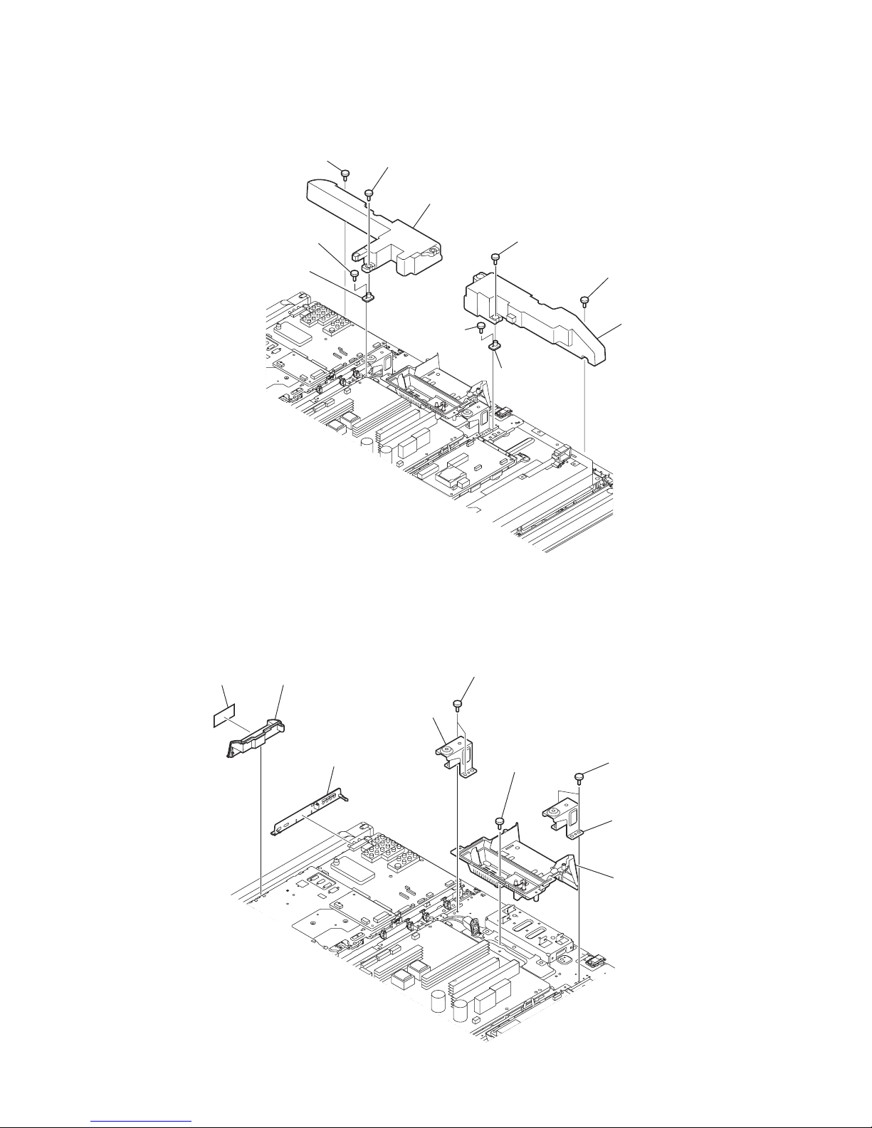
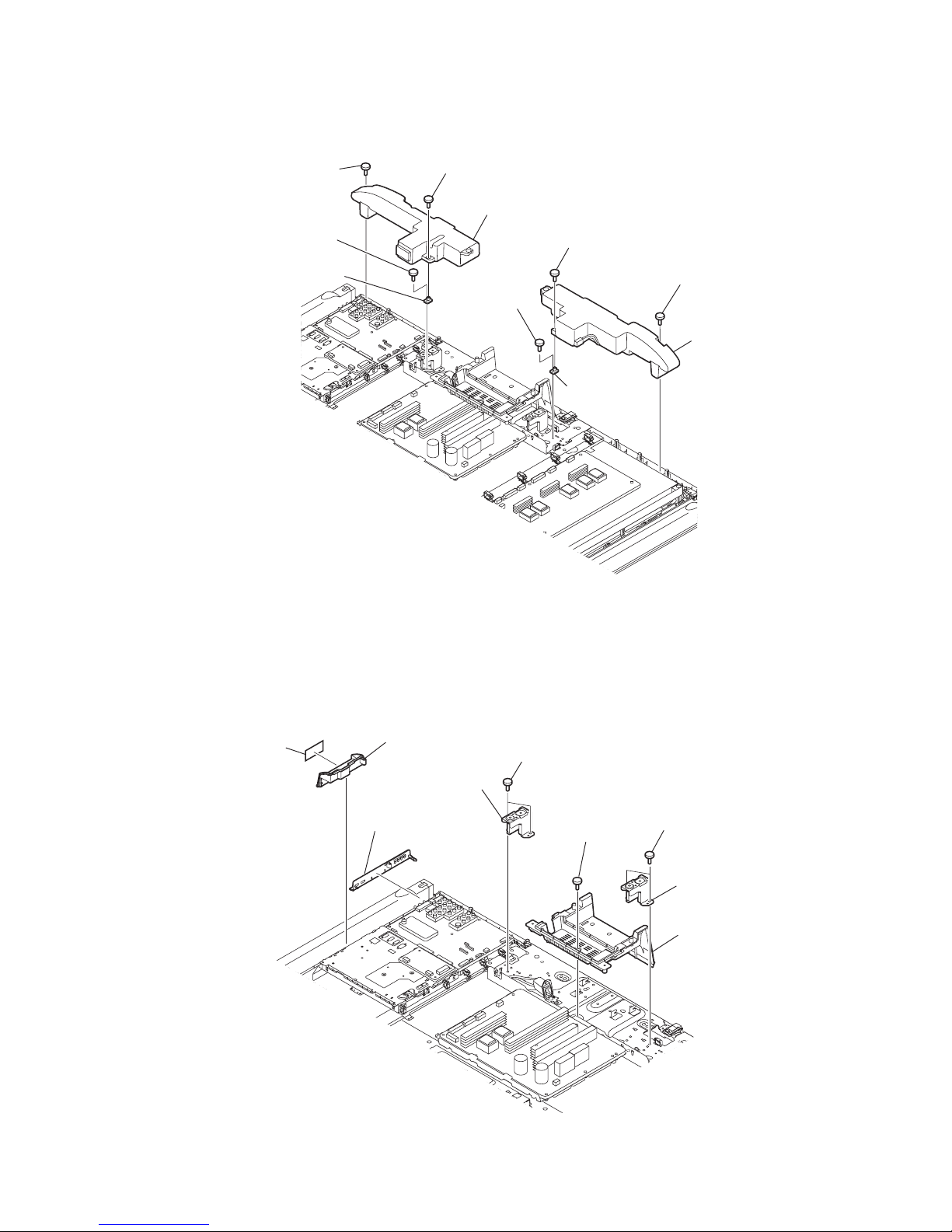
1-1-13. SPINE FRAME REMOVAL
1-1-14. SPEAKER BOX ASSY REMOVAL
1 Three screws
(+PSW M4X8)
3 Three screws
(+PSW M4X8)
2 Spine frame
4 Spine frame
6 One screw
(+BV 3X12)
1 One screw
(+BV 3X12)
7 Cover
2 Cabinet cover L
qg Illumination module
qs SP box assy
qd One screw
(+BV 3X12)
qf Cover
5 SP box assy
3 Grille
4 Four screws
(+BVTP2 4X16)
0 Grille
qa Four screws
(+BVTP2 4X16)
8 One screw
(+BV 3X12)
9 Cabinet cover R
KDL-40/46/55XBR45 (AUS), 40/46/55X4500 (NZ, ES) 1-8
KDL-40XBR45/40X4500
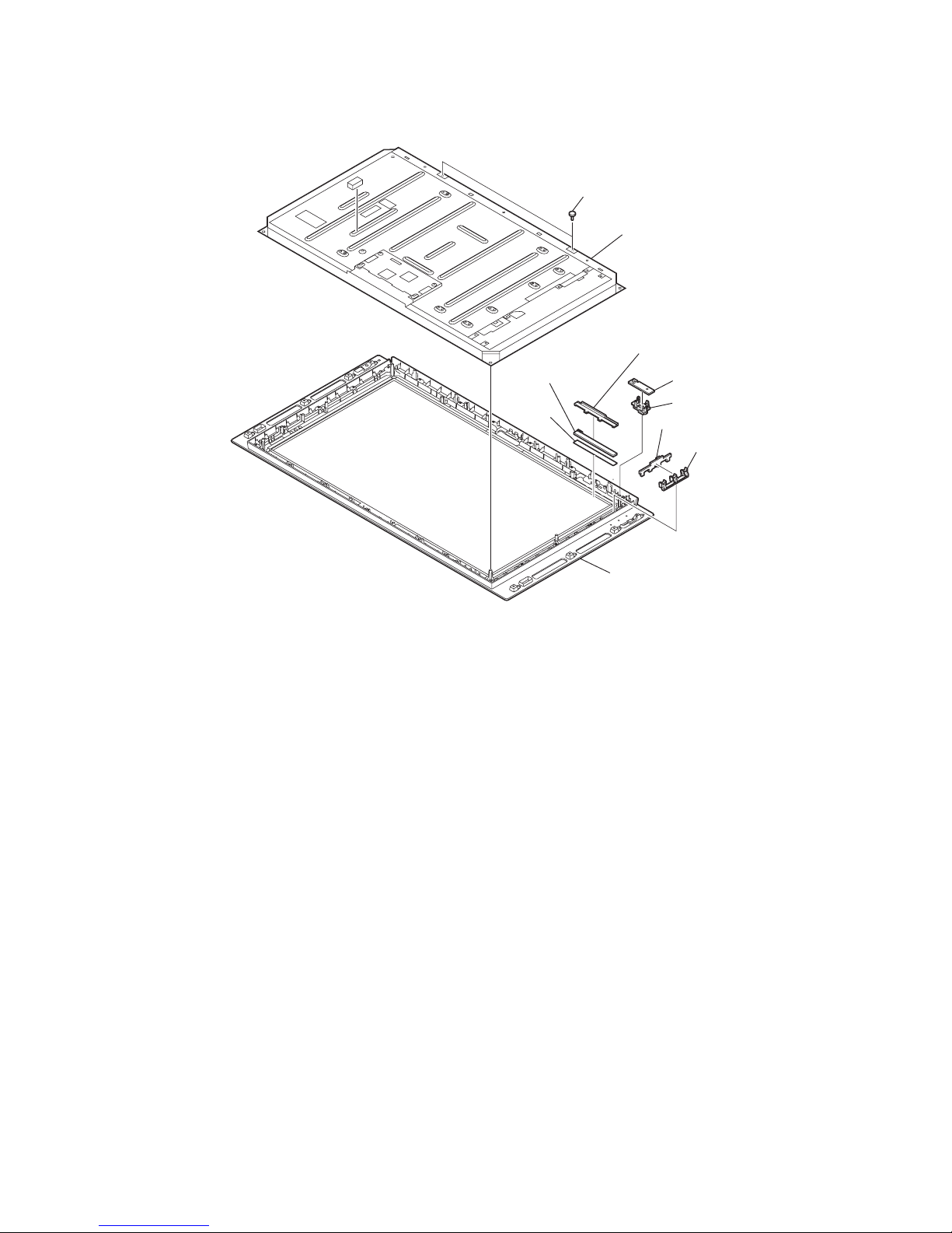
1-1-15. LCD PANEL, H3VM BOARD AND H4 BOARD REMOVAL
8 Two screws
(+BVTP2 4X16)
1 LED bracket
2 H3VM board
4 H4 board
3 Guide light
5 Touch holder
6 Touch sensor
module
7 Touch
sheet
9 LCD panel
0 Bezel

KDL-40/46/55XBR45 (AUS), 40/46/55X4500 (NZ, ES) 1-9
1-2. KDL-46XBR45/46X4500
1-2-1. REAR COVER REMOVAL
1-2-2. STAND ASSY REMOVAL
1 Four screws
(+BVTP2 4X16)
3 Two screws
(+BV 3X12)
4 Rer cover (46Z)
1 Eight screws
(+BVTP2 4X16)
1 Six screws
(+BVTP2 4X16)
2 Four screws
(+PSW M5X16)
1 Two screws
(+PSW M5X16)
3 Two screws
(+PSW M5X8)
4 Vesa (TOP) frame
1 Two screws
(+PSW M5X16)
2 Stand assy (L-4)

KDL-40/46/55XBR45 (AUS), 40/46/55X4500 (NZ, ES) 1-10
KDL-46XBR45/46X4500
1-2-3. H1VM BOARD REMOVAL
1-2-4. PANEL FIN REMOVAL
1 Power bracket
2 Power button
3 H1VM board
1 One screw
(+PSW M5X8)
2 Top frame
6 Panel fin
8 Panel fin
5 Two screws
(+PSW 3X8)
7 Two screws
(+PSW 3X8)
3 One screw
(+PSW M5X8)
4 Top frame
KDL-40/46/55XBR45 (AUS), 40/46/55X4500 (NZ, ES) 1-11
KDL-46XBR45/46X4500
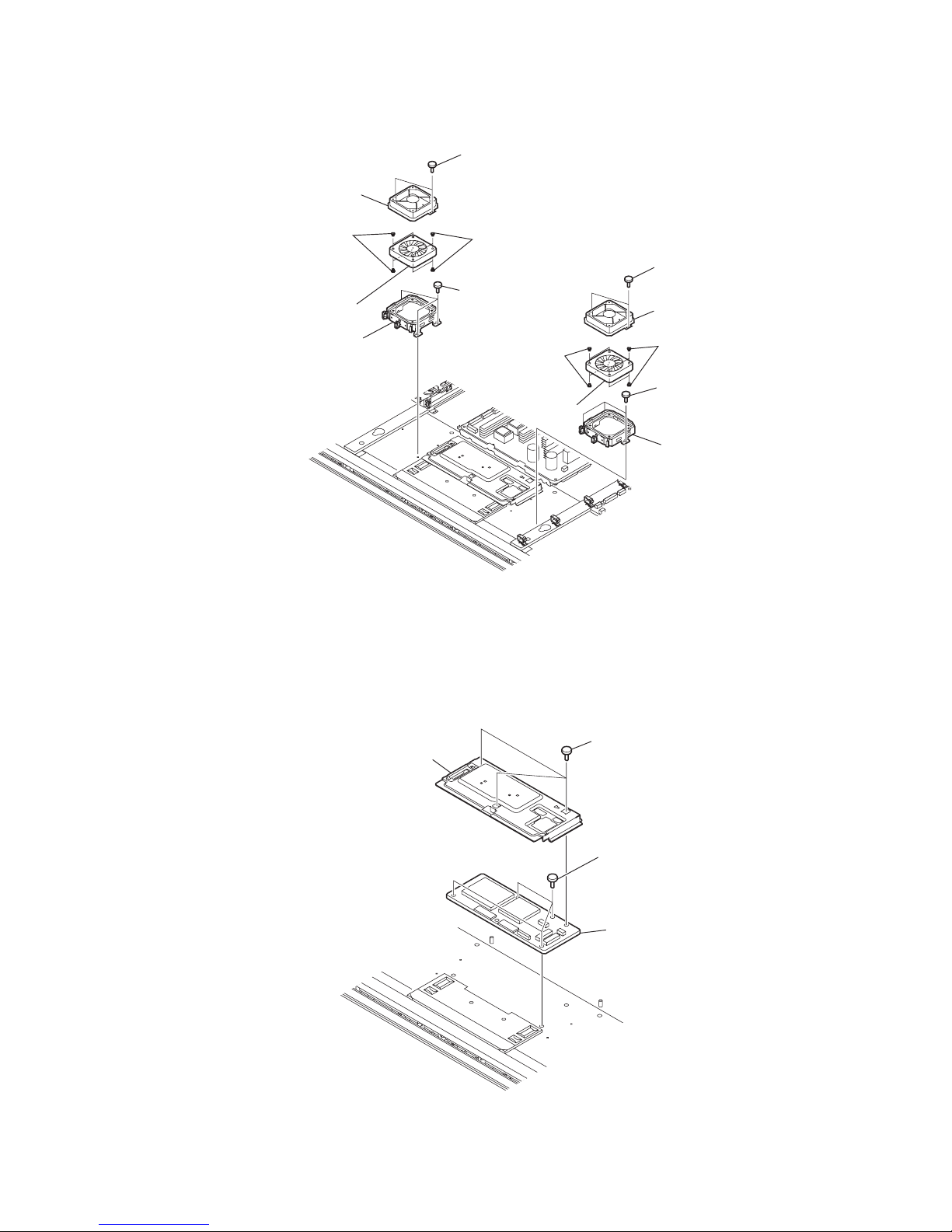
1-2-5. FAN REMOVAL
1-2-6. CB1 BOARD REMOVAL
1 Two screws
(+BVST 3X8)
2 Fan cover
5 Three screws
(+PSW 3X8)
7 Two screws
(+BVST 3X8)
qa Three screws
(+PSW 3X8)
qs Fan bracket
8 Fan cover
4 D.C. Fan
0 D.C. Fan
6 Fan bracket
3 Fan damper
3 Fan damper
9 Fan damper
9 Fan damper
2 CB shield assy
1 Three screws
(+PSW 3X8)
3 Four screws
(+PSW 3X8)
4 CB1 board
KDL-40/46/55XBR45 (AUS), 40/46/55X4500 (NZ, ES) 1-12
KDL-46XBR45/46X4500
1-2-7. SP BOX (WOOFER) REMOVAL
1-2-8. UNDER COVER, SIDE JACK BRACKET AND CARD BRACKET REMOVAL
1 One screw
(+PWTP2 4X16)
1 One screw
(+PWTP2 4X16)
2 SP Box assy
(WOOFER)
3 One screw
(+BVST 3X8)
4 AWF bracket
5 One screw
(+PWTP2 4X16)
5 One screw
(+PWTP2 4X16)
6 SP Box assy
(WOOFER)
7 One screw
(+BVST 3X8)
8 AWF bracket
1 Two screws
(+PSW M5X8)
2 Vesa (BTM) frame
3 Two screws
(+PSW M5X8)
4 Vesa (BTM) frame
5 One screw
(+PSW M5X16)
6 Under cover
7 Card bracket
8 MS cover
9 Side jack bracket
KDL-40/46/55XBR45 (AUS), 40/46/55X4500 (NZ, ES) 1-13
KDL-46XBR45/46X4500
1-2-9. G6 BOARD REMOVAL
1-2-10. GL BOARD REMOVAL
1 Two screws
(+PSW 3X8)
2 GL board
1 Four screws
(+PSW 3X8)
2 Two screws
( +BV 3X12)
1 Three screws
(+PSW 3X8)
1 Three screws
(+PSW 3X8)
3 G6 board
4 G6 bracket

KDL-40/46/55XBR45 (AUS), 40/46/55X4500 (NZ, ES) 1-14
KDL-46XBR45/46X4500
1-2-11. K2 BOARD REMOVAL
1 Two screws
(+PSW 3X8)
2 Three screws
(+PSW M3X5)
3 Two screws
(SP 4-4O UNC)
1 One screw
(+BVST 3X8)
4 FB shield
1-2-12. FB SHIELD REMOVAL
1 Four screws
(+PSW M3X5)
1 K2 board
KDL-40/46/55XBR45 (AUS), 40/46/55X4500 (NZ, ES) 1-15
KDL-46XBR45/46X4500
1-2-13. AAS AND FBA BOARDS REMOVAL
1-2-14. AC INLET REMOVAL
1 Two screws
(+BVST 3X8)
1 Four screws
(+BVST 3X8)
2 AAS board
1 Three screws
(+BVST 3X8)
3 Five screws
(+BVST 3X8)
4 FBA board
6 One screw
(+BVTP2 4X16)
3 Five screws
(+BVST 3X8)
5 Three screws
(+PSW M3X5)
7 Main bracket
9 Two screws
(+PSW M5X8)
9 Four screws
(+PSW M5X8)
4 AC inlet
1 One screw
(+BVST 3X8)
3 Two screws
(+KTT 3X10 (S TYPE))
5 One screw
(+PSW M3X5)
7 RF module
6 RF bracket
8 Four screws
(+BVTP2 4X16)
9 Two screws
(+PSW M5X8)
2 AC inlet bracket
0 Bottom frame (46Z)
 Loading...