

Sony KDL-40SL140, KDL-46SL140 Service Manual
HISTORY INFORMATION FOR THE FOLLOWING MANUAL:
SERVICE MANUAL
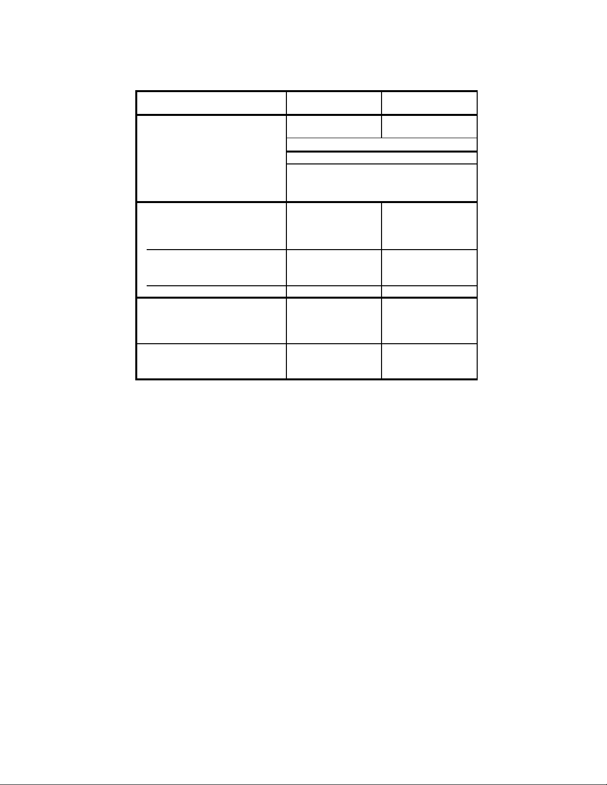
MODEL NAME REMOTE COMMANDER DESTINATION
KDL-40SL140
KDL-40SL140
KDL-40SL140
KDL-46SL140
KDL-46SL140
KDL-46SL140
RM-YD026 US
RM-YD026 CANADA
RM-YD026 MEXICO
RM-YD026 US
RM-YD026 CANADA
RM-YD026 MEXICO
MA2F
CHASSIS
ORIGINAL MANUAL ISSUE DATE: 7/2008
REVISION DATE SUBJECT
7/2008 No revisions or updates are applicable at this time.
LCD DIGITAL COLOR TELEVISION
9-883-794-01
Self Diagnosis
Supported model
SERVICE MANUAL
MODEL NAME REMOTE COMMANDER DESTINATION
KDL-40SL140
KDL-40SL140
KDL-40SL140
KDL-46SL140
KDL-46SL140
KDL-46SL140
RM-YD026 US
RM-YD026 CANADA
RM-YD026 MEXICO
RM-YD026 US
RM-YD026 CANADA
RM-YD026 MEXICO
MA2F
CHASSIS
9-883-794-01
KDL-46SL140 RM-YD026
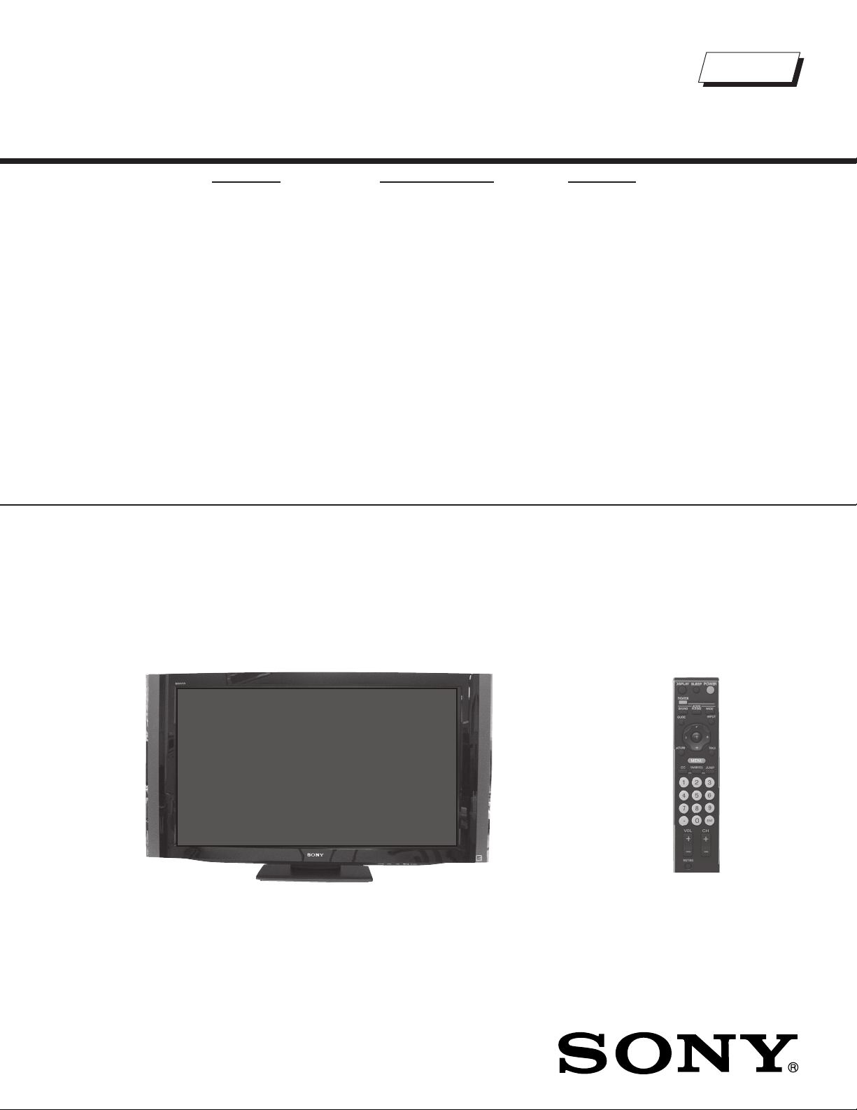
LCD DIGITAL COLOR TELEVISION

KDL-40SL140/46SL140
TABLE OF CONTENTS
SECTION TITLE PAGE SECTION TITLE PAGE
Specifi cations ................................................................................. 4
Warnings and Cautions .................................................................. 6
Safety-Related Component Warning .............................................. 7
Safety Check-Out ........................................................................... 9
Self-Diagnostic Function ............................................................... 10
SECTION 1: DISASSEMBLY ............................................................... 12
1-1. Rear Cover Removal ............................................................ 12
1-2. Switch Unit Removal (Contains HM1 Board) ....................... 12
1-3. Side Jack Bracket and BM5 Board Removal ....................... 13
1-4. Power Unit (IP5Z Board) Removal ....................................... 13
1-5. Table-Top Stand Assembly and Under Cover Removal ....... 14
1-6. Structural Frames and Brackets Removal
(KDL-40SL140 Only) ............................................................ 14
1-7. Structural Frames and Brackets Removal
(KDL-46SL140 Only) ............................................................ 15
1-8 Speakers, Light Guide and HM5 Board Removal ................ 16
1-9. LCD Panel Removal ............................................................. 17
1-9-1. Cleaning the LCD Panel ............................................ 17
1-10. Balancer (MT Inverter) Board Removal ............................... 18
WIRE DRESSING ........................................................................ 19
KDL-40SL140 Only .............................................................. 19
KDL-46SL140 Only .............................................................. 28
SECTION 2: SERVICE ADJUSTMENTS ............................................. 37
2-1. Resetting the TV to the Factory Defaults ............................. 37
SECTION 3: DIAGRAMS ..................................................................... 38
3-1. Circuit Boards Location ........................................................ 38
3-2. Printed Wiring Boards and
Schematic Diagrams Information ......................................... 38
3-3. Block Diagram ...................................................................... 40
3-4. Schematics and Supporting Information .............................. 41
BM5 Board Schematic Diagram (1 of 12) ............................ 41
BM5 Board Schematic Diagram (2 of 12) ............................ 42
BM5 Board Schematic Diagram (3 of 12) ............................ 43
BM5 Board Schematic Diagram (4 of 12) ............................ 44
BM5 Board Schematic Diagram (5 of 12) ............................ 45
BM5 Board Schematic Diagram (6 of 12) ............................ 46
BM5 Board Schematic Diagram (7 of 12) ............................ 47
BM5 Board Schematic Diagram (8 of 12) ............................ 48
BM5 Board Schematic Diagram (9 of 12) ............................ 49
BM5 Board Schematic Diagram (10 of 12) .......................... 50
BM5 Board Schematic Diagram (11 of 12) ........................... 51
BM5 Board Schematic Diagram (12 of 12) .......................... 52
HM5 Board Schematic Diagram ........................................... 54
IP5Z Board Schematic Diagram (1 of 2)
(KDL-40SL140 Only) ....................................................... 56
IP5Z Board Schematic Diagram (2 of 2)
(KDL-40SL140 Only) ....................................................... 57
IP5Z Board Schematic Diagram (1 of 2)
(KDL-46SL140 Only) ....................................................... 58
IP5Z Board Schematic Diagram (2 of 2)
(KDL-46SL140 Only) ....................................................... 59
3-5. Semiconductors ................................................................... 62
KDL-40SL140/46SL140
SECTION 4: EXPLODED VIEWS ........................................................ 63
4-1. Rear Cover Assembly and Table-Top Stand Assembly ....... 63
4-2. Chassis ................................................................................ 64
4-3. Connectors ........................................................................... 65
4-4. Bezel Assembly, LCD Panel and Speakers ......................... 66
4-5. Screw Legend ...................................................................... 67
SECTION 5: ELECTRICAL PARTS LIST ............................................ 68
APPENDIX A: ENCRYPTION KEY COMPONENTS ..........................A-1
3
SPECIFICATIONS
KDL-40SL140/46SL140
Power Requirements
120 V AC, 60 Hz
VIDEO (IN) 1/2/3
S VIDEO (4-Pin Mini DIN) (VIDEO 1 Only)
Y: 1.0 Vp-p, 75 ohms unbalanced, sync negative
C: 0.286 Vp-p (Burst signal), 75 ohms
VIDEO
1 Vp-p, 75 ohms unbalanced, sync negative
AUDIO
500 mVrms (100% modulation)
Impedance:47 kilohms
COMPONENT IN 1/2
YP
(Component Video)
BPR
Y:1.0 Vp-p, 75 ohms unbalanced, sync negative
PB:0.7 Vp-p, 75 ohms
PR:0.7 Vp-p, 75 ohms
Signal format: 480i, 480p, 720p, 1080i
AUDIO
500 mVrms (100% modulation)
Impedance: 47 kilohms
HDMI IN 1/2/3/4
HDMI: Video: 480i, 480p, 720p, 1080i, 1080p
Audio: Two channel linear PCM 32, 44.1 and
48 kHz, 16, 20 and 24 bits
AUDIO: 500 mVrms (100% modulation)
Impedance: 47 kilohms
DIGITAL AUDIO OUT (OPTICAL)
PCM optical signal
AUDIO OUT (VAR/FIX)
500 mVrms (Typical)
PC IN
D-sub 15-pin, analog RGB, 0.7 Vp-p, 75 ohms, positive
PC AUDIO INPUT:
Stereo mini jack, 500 mVrms, 47 kilohms
Trademark Information
Macintosh is a trademark licensed to Apple,
Inc., registered in the U.S.A. and other countries.
Manufactured under license from Dolby
Laboratories. “Dolby” and the double-D symbol
are trademarks of Dolby Laboratories.
HDMI, the HDMI logo and High-Definition
Multimedia Interface are trademarks or
registered trademarks of HDMI Licensing, LLC.
TruSurround XT, SRS and ( ) symbol are
trademarks of SRS Labs, Inc. TruSurround XT
technology is incorporated under license from
SRS Labs, Inc.
Fergason Patent Properties, LLC:
U.S. Patent No. 5, 717, 422
U.S. Patent No. 6, 816, 141
Blu-ray is a trademark.
“BRAVIA” and , , BRAVIA
Theatre Sync and DMPORT are trademarks or
registered marks of Sony Corporation.
“PLAYSTATION” is a registered trademark
and “PS3” is a trademark of Sony Computer
Entertainment Inc.
KDL-40SL140/46SL140
Design and specifi cations are subject to change without notice.
4
Power Consumption
Speaker Output (W)
Speaker/Full Range (2)
Dimensions (W x H x D)
with stand
without stand
wall -mount hole pattern (mm)
Mass
with stand
without stand
in use
in standby
mm
in
mm
in
mm
in
kg
lbs
kg
lbs
KDL-46SL140KDL-40SL140
220W
300W
Less than 1W
10W + 10W
146 x 35
3/4
3/8
5
x 1
in
1,119 x 654 x 276 mm
1/8
x 25
3/4
x 10
44
1,252 x 734 x 276 mm
7/8
in
49
3/8
x 29 x 10
7/8
in
1,119 x 615 x 111 mm 1,252 x 691 x 116 mm
1/8
1/4
44
x 4
3/8
in 49
x 24
300 x 300
22.0 kg
49 lbs
19.5 kg
43 lbs
All measurements are approximations.
3/8
x 27
300 x 300
28.0 kg
62 lbs
25.5 kg
57 lbs
1/4
x 4
5/8
in
KDL-40SL140/46SL140
Television system
NTSC: American TV Standard
ATSC (8VSB terrestrial): ATSC compliant 8VSB
QAM on cable: ANSI/SCTE 07 2000
Channel coverage
Analog Digital
Terrestrial 2-69 2-69
Cable 1-125 1-135
Antenna
75-ohm external terminal for VHF/UHF
Panel System
LCD (Liquid Crystal Display) Panel
Display Resolution (horizontal x vertical):
1,920 dots x 1,080 lines
Screen Size (measured diagonally)
approx. 40 inches (KDL-40SL140 Only)
approx. 46 inches (KDL-46SL140 Only)
Supplied Accessories
Remote Commander RM-YD026
Two Size AA (R6) Batteries
Cable Holder
Operating Instructions
Quick Setup Guide
Warranty Card
Online Registration Card (USA and Canada Only)
Safety and Regulartory Booklet
Attaching to the Table-Top Stand
Screws (4)
Optional Accessories
Connecting Cables
Wall-Mount Bracket
SU-WL500
Support Belt Kit
TV Stand
SU-FL300M (KDL-40SL140 Only)
SU-FL300L (KDL-46SL140 Only)
Floor Stand
SU-FL71M
KDL-40SL140/46SL140
5
KDL-40SL140/46SL140
WARNINGS AND CAUTIONS
CAUTION
These servicing instructions are for use by qualifi ed service personnel only. To reduce the risk of electric shock, do not perform any servicing other
than that contained in the operating instructions unless you are qualifi ed to do so.
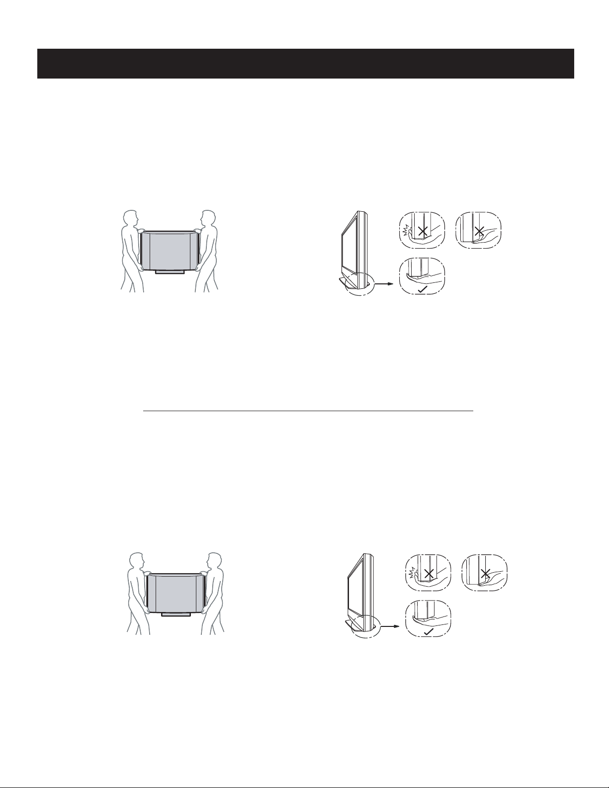
CARRYING THE TV
To avoid dropping the TV and causing serious injury, be sure to follow
these guidelines:
s Before carrying the TV, disconnect all cables.
s Carrying the large size TV requires two or more people.
s When you carry the TV, place your hand as illustrated and hold it
securely. Do not put stress on the LCD panel.
s When lifting or moving the TV, hold it firmly from the bottom. Place
your palm directly under the panel.
s When carrying, do not subject the TV to shocks or vibration, or
excessive force.
s Place your palm directly underneath, but do not squeeze the
panel’s speaker grill area.
WARNING!!
An isolation transformer should be used during any service to avoid possible shock hazard, because of live chassis. The chassis of this receiver is
directly connected to the ac power line.
! SAFETY-RELATED COMPONENT WARNING!!
Components identifi ed by shading and ! mark on the schematic diagrams, exploded views, and in the parts list are critical for safe operation. Replace
these components with Sony parts whose part numbers appear as shown in this manual or in supplements published by Sony. Circuit adjustments that
are critical for safe operation are identifi ed in this manual. Follow these procedures whenever critical components are replaced or improper operation is
suspected.
ATTENTION!!
Ces instructions de service sont à l’usage du personnel de service qualifi é seulement. Pour prévenir le risque de choc électrique, ne pas faire
l’entretien autre que celui contenu dans le Mode d’emploi à moins que vous soyez qualifi é faire ainsi.
POUR TRANSPORTER LE TÉLÉVISEUR
Assurez-vous de suivre ces consignes pour éviter de laisser tomber le
téléviseur et de provoquer des blessures graves :
s Avant de transporter le téléviseur, débranchez tous les câbles.
s Le transport du téléviseur doit être effectué par au moins deux
personnes.
s Lorsque vous le transportez, placez vos mains tel que cela est illustré
et tenez solidement l’appareil. N’appliquez pas de pression sur
l’écran ACL.
s Lorsque vous levez ou déplacez le téléviseur, assurez-vous de tenir
solidement de la base. Placez la paume des mains directement sous
le panneau.
s Lorsque vous transportez le téléviseur, ne le soumettez pas à des
chocs ou vibrations, ni à une force excessive.
s Positionnez votre paume directement sous l’appareil et veillez à
ne pas exercer de pression contre la grille des haut-parleurs
du panneau.
Afi n d’eviter tout risque d’electrocution provenant d’un chássis sous tension, un transformateur d’isolement doit etre utilisé lors de tout dépannage. Le
chássis de ce récepteur est directement raccordé à l’alimentation du secteur.
! ATTENTION AUX COMPOSANTS RELATIFS A LA SECURITE!!
Les composants identifi es par une trame et par une marque ! sur les schemas de principe, les vues explosees et les listes de pieces sont d’une
importance critique pour la securite du fonctionnement. Ne les remplacer que par des composants Sony dont le numero de piece est indique dans le
present manuel ou dans des supplements publies par Sony. Les reglages de circuit dont l’importance est critique pour la securite du fonctionnement
sont identifi es dans le present manuel. Suivre ces procedures lors de chaque remplacement de composants critiques, ou lorsqu’un mauvais
fonctionnement suspecte.
KDL-40SL140/46SL140
6
SAFETY-RELATED COMPONENT WARNING
KDL-40SL140/46SL140
There are critical components used in LCD color TVs that are important for safety. These components are identifi ed with shading and
mark on the schematic diagrams and the electrical parts list. It is essential that these critical parts be replaced only with the part number
specifi ed in the electrical parts list to prevent electric shock, fi re, or other hazard.
NOTE: Do not modify the original design without obtaining written permission from the manufacturer or you will void the original parts and
labor guarantee.
!
USE CAUTION WHEN HANDLING THE LCD PANEL
When repairing the LCD panel, be sure you are grounded by using a wrist band.
When installing the LCD panel on a wall, the LCD panel must be secured using the 4 mounting holes on the rear cover.
To avoid damaging the LCD panel:
do not press on the panel or frame edge to avoid the risk of electric shock.
do not scratch or press on the panel with any sharp objects.
do not leave the module in high temperatures or in areas of high humidity for an extended period of time.
do not expose the LCD panel to direct sunlight.
avoid contact with water. It may cause a short circuit within the module.
disconnect the AC adapter when replacing the backlight (CCFL) or inverter circuit.
(High voltage occurs at the inverter circuit at 650Vrms.)
always clean the LCD panel with a soft cloth material.
use care when handling the wires or connectors of the inverter circuit. Damaging the wires may cause a short.
protect the panel from ESD to avoid damaging the electronic circuit (C-MOS).
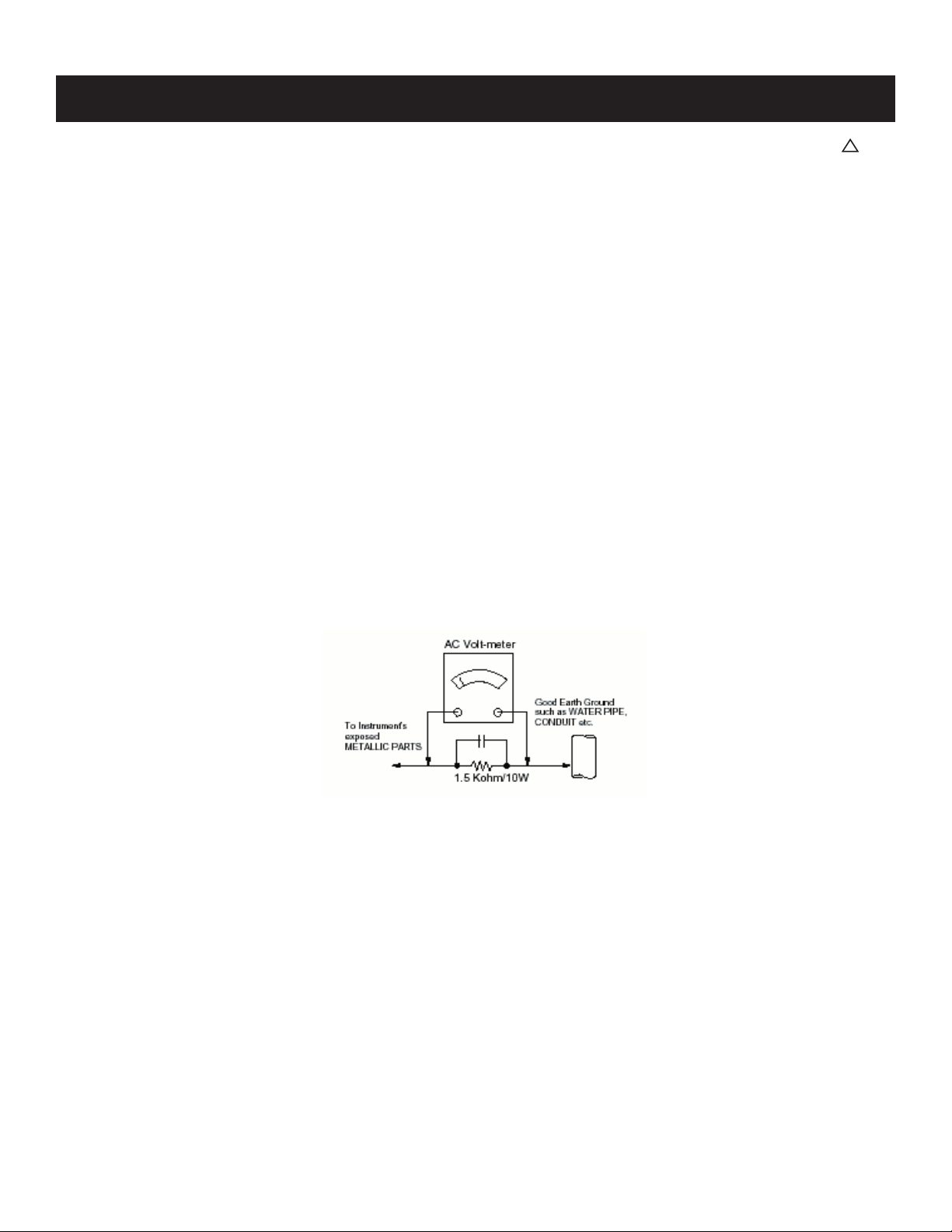
LEAKAGE CURRENT HOT CHECK CIRCUIT
KDL-40SL140/46SL140
7
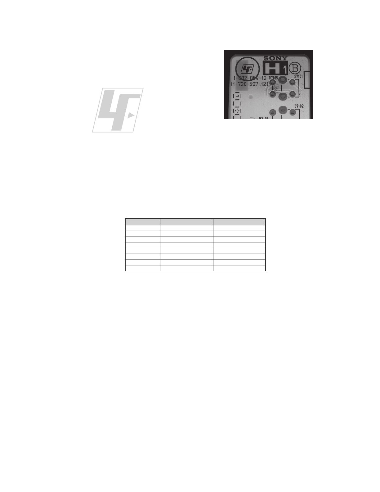
The circuit boards used in these models have been processed using
Lead Free Solder. The boards are identified by the LF logo located
close to the board designation e.g. H1 etc [ see example ]. The
servicing of these boards requires special precautions to be taken as
outlined below.
KDL-40SL140/46SL140
example 1
It is strongly recommended to use Lead Free Solder material in order to guarantee optimal quality of new solder joints.
Lead Free Solder is available under the following part numbers :
rebmuntraP retemaiD skrameR
91-500-046-7mm3.0gK52.0
02-500-046-7mm4.0gK05.0
12-500-046-7mm5.0gK05.0
22-500-046-7mm6.0gK52.0
32-500-046-7mm8.0gK00.1
42-500-046-7mm0.1gK00.1
52-500-046-7mm2.1gK00.1
62-500-046-7mm6.1gK00.1
Due to the higher melting point of Lead Free Solder the soldering iron tip temperature needs to be set to 370 degrees centigrade.
This requires soldering equipment capable of accurate temperature control coupled with a good heat recovery characteristics.
For more information on the use of Lead Free Solder, please refer to
http://www.sony-training.com
KDL-40SL140/46SL140
8
KDL-40SL140/46SL140
r
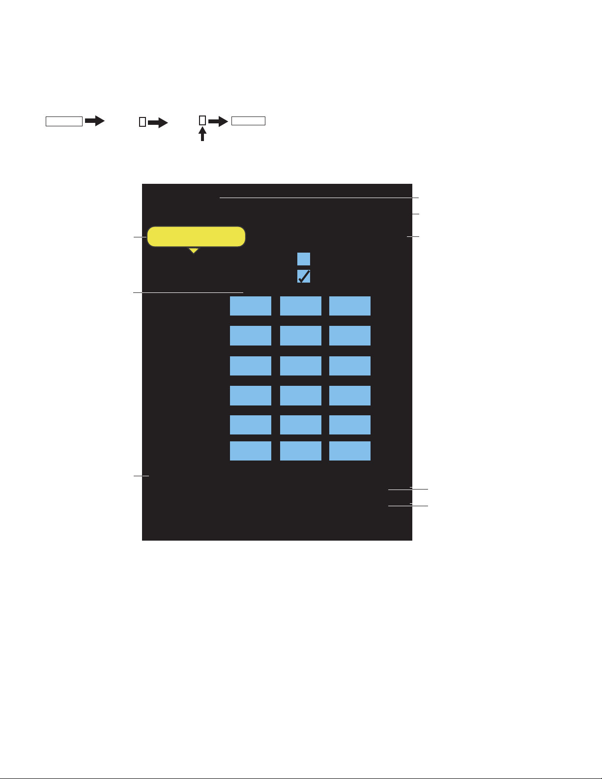
Viewing the Diagnostic List
1. TV must be in standby mode. (Power off).
2. Press the following buttons on the Remote Commander within a second of each other:
DISPLAY
The Self Check list displays. This is the SAME as accessing Service Adjustments.
Results for all of the following diagnostic items are displayed at the bottom of the screen. No error has occurred if the screen displays a “0”.
Channel 5 Volume +
POWER
.
Resets all settings
to the Factory Defaults
Stored Data
from ADC calibration
(from factory)
Diagnostic
List
QR0.5-C510
Model Information: 40SL140 8000001
Factory Default
Power On Time: 00001H
SMPTE
ADC Auto Calibration
Cr Y Cb
Gain
424
ColorBar100
1608 424
ITU 709
Offset
Gain
1020
420
128
1592
1020
422
ITU 601
Offset
Gain
1020
456
128
1840
1020
460
VGA
Offset
16 8
16
2:MAIN POWER 0 6:BL 0
3:DC ALERT1 0 7:TEMP 1
4:DC ALERT2 0 8:Audio 0
5:DC ALERT3 0
Software Version
Model Information & Serial Numbe
Power Time
Indicates an error was detected
Indicates no error was detected
Clearing the Diagnostic List
CAUTION: To remove the error indicator number you have to reset the settings back to the Factory Defaults. This action over-writes all customer
settings.
1. Using the remote commander, select Factory Default button.
2. To reset the Diagnostic List, select Ye
3. To start Auto Program, select Yes.
NOTE: Allow 30+ minutes for Auto Program to complete.
4. Using the customers information, reset their adjustments.
Before performing this reset, contact the customer to determine what adjustments they have made.
s.
KDL-40SL140/46SL140
11
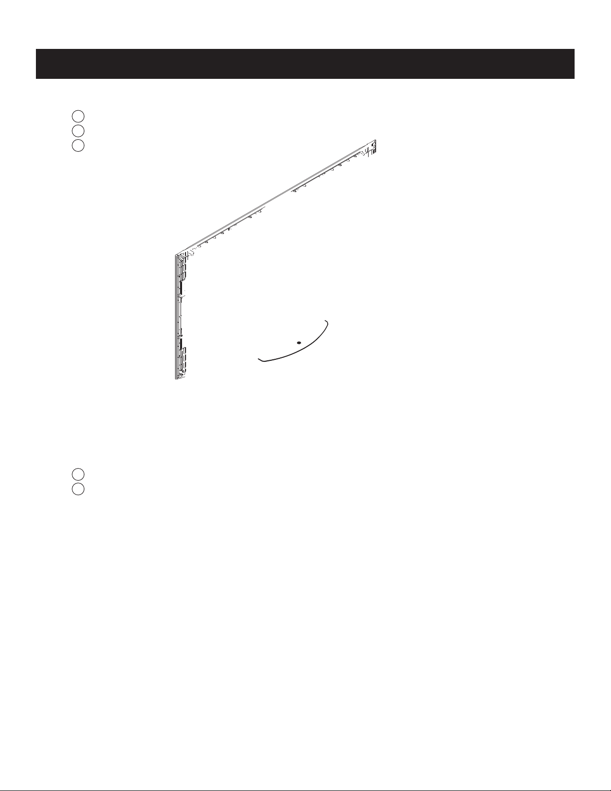
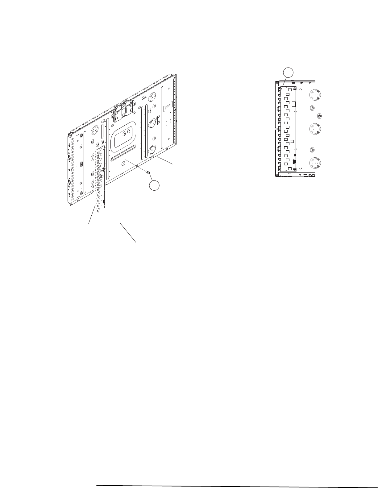
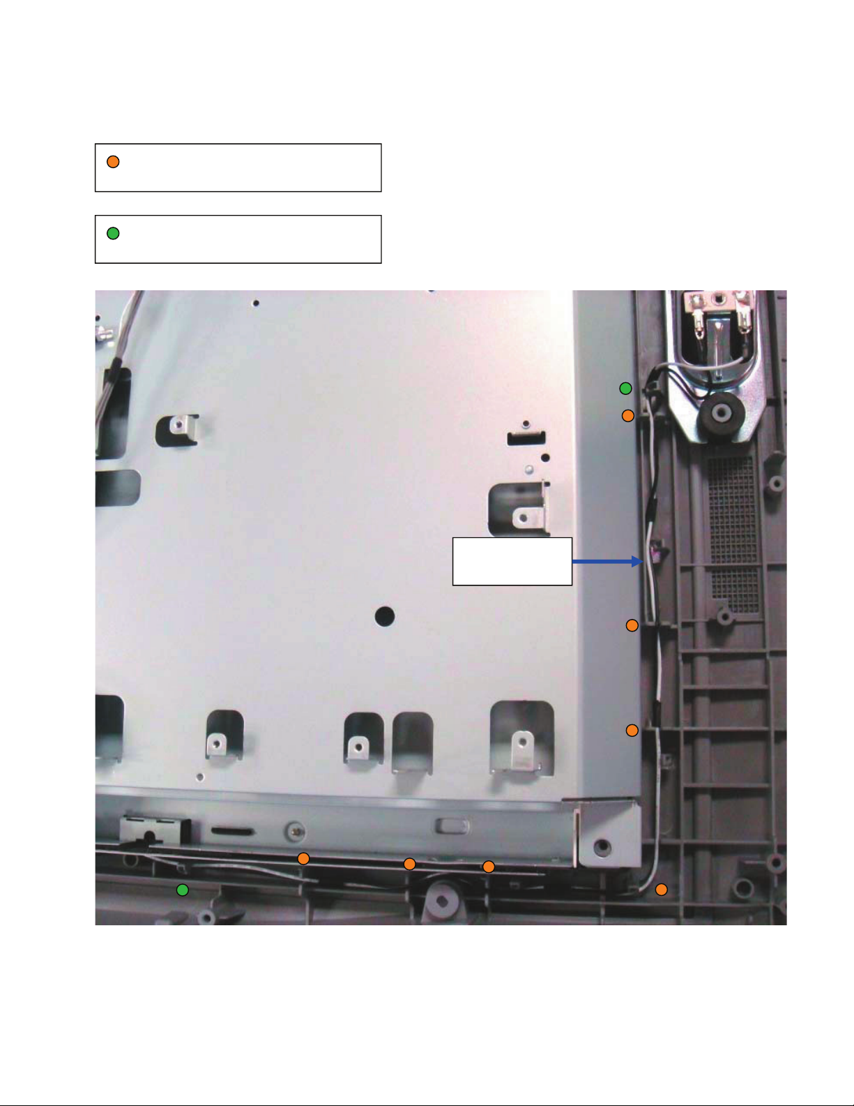
1-1. REAR COVER REMOVAL
Remove 2 screws from Terminal Position
1
Remove 6 screws
2
Remove 17 screws (KDL-40SL140 ONLY)
3
Remove 21 screws (KDL-46SL140 ONLY)
KDL-40SL140/46SL140
SECTION 1: DISASSEMBLY
1-2. SWITCH UNIT REMOVAL (CONTAINS HM1 BOARD)
Remove from bezel
1
Disconnect 1 connector
2
KDL-40SL140/46SL140
12
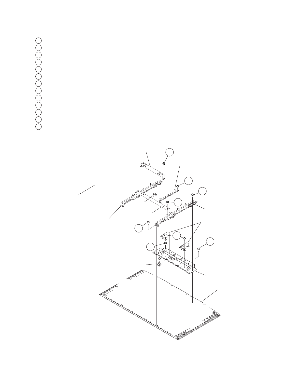
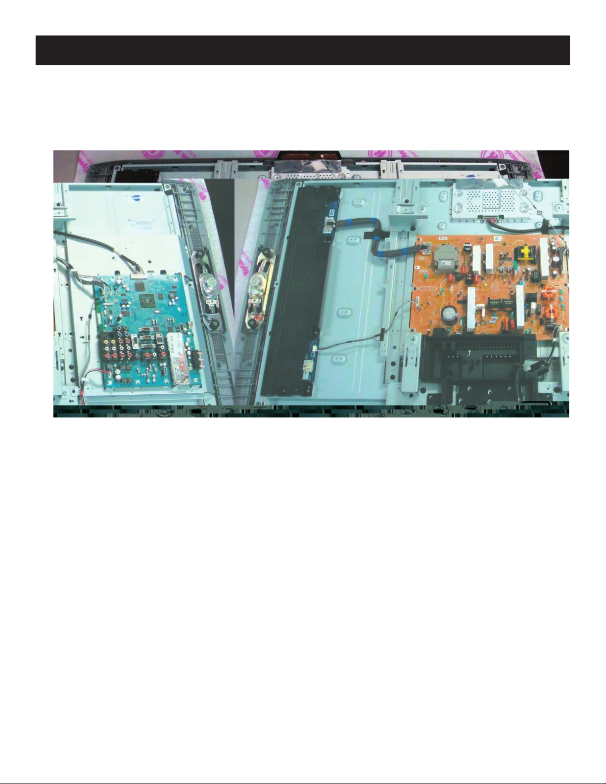
1-7. STRUCTURAL FRAMES AND BRACKETS REMOVAL (KDL-46SL140 ONLY)
Remove 3 screws from Main Bracket and Spine frame
1
Remove 1 screw from Main Bracket and LCD Panel
2
Remove 1 screw from Main Bracket and Center Cabinet
3
Remove 2 screws from Top Vesa Bracket
4
Remove 1 screw from G Board Support
5
Remove 2 screws from G Frame
6
Remove 2 screws from Center Frame
7
Remove 10 screws from Spine Frames
8
Remove 2 screws from Spine Frames
9
Remove 4 screws from both Bottom Vesa Brackets
10
Remove 4 screws from Bottom Bracket
11
Remove 1 screw from Bottom Bracket
12
Remove 1 screw from G Board Support
13
KDL-40SL140/46SL140
Main Bracket
Spine Frame
Top Vesa Bracket
G Support
Center Frame
9
11
G Support
4
G Frame
6
8
7
Spine Frame
Bottom Vesa Bracket
10
12
Bottom Bracket
Bezel
KDL-40SL140/46SL140
15
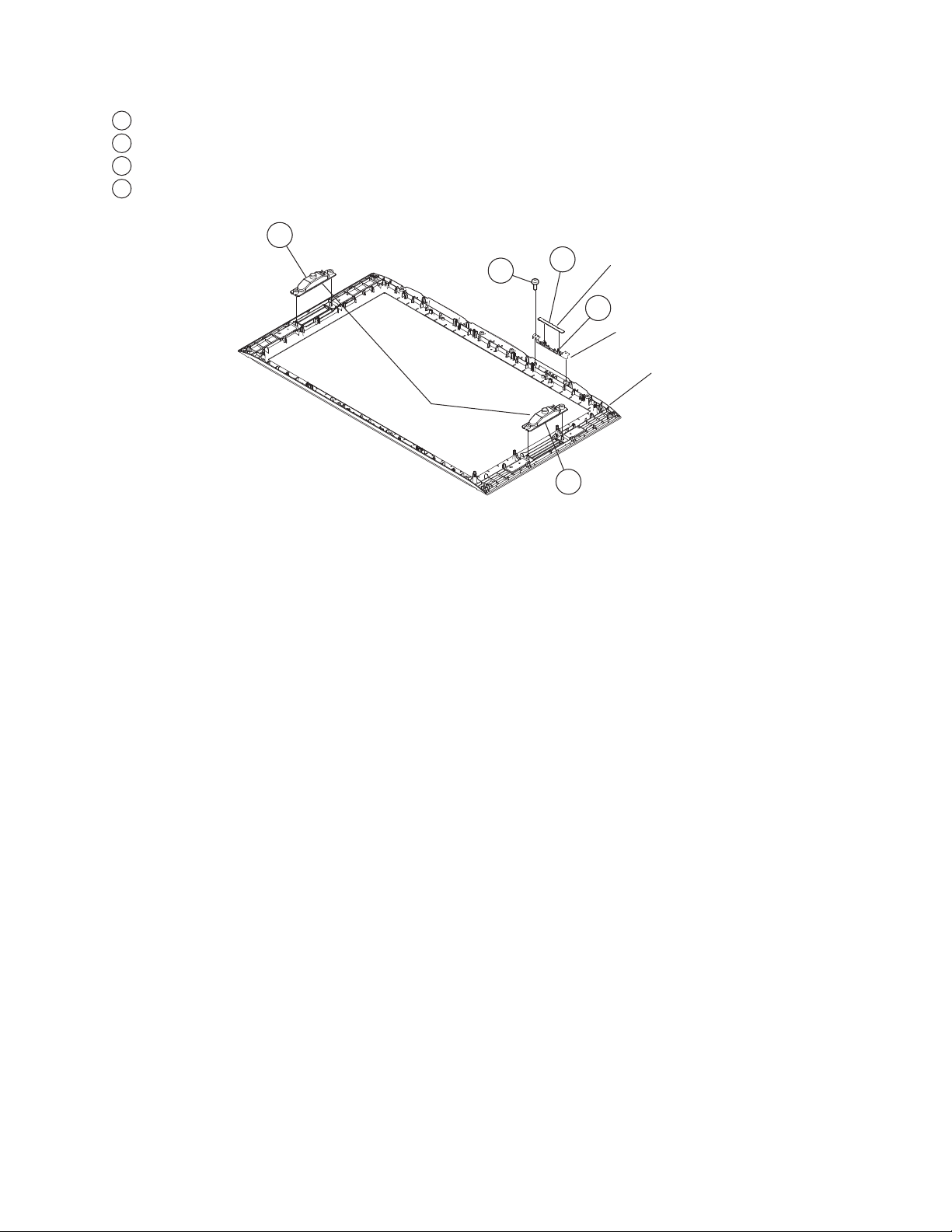
1-8 SPEAKERS, LIGHT GUIDE AND HM5 BOARD REMOVAL
Disconnect 1 connector
1
Release hooks and remove from Light Guide
2
Remove 2 screws
3
Slide out Speakers from Front Cabinet
4
4
3
Speaker
1
4
KDL-40SL140/46SL140
HM5 Board
2
Light Guide
Front Cabinet Assembly
KDL-40SL140/46SL140
16
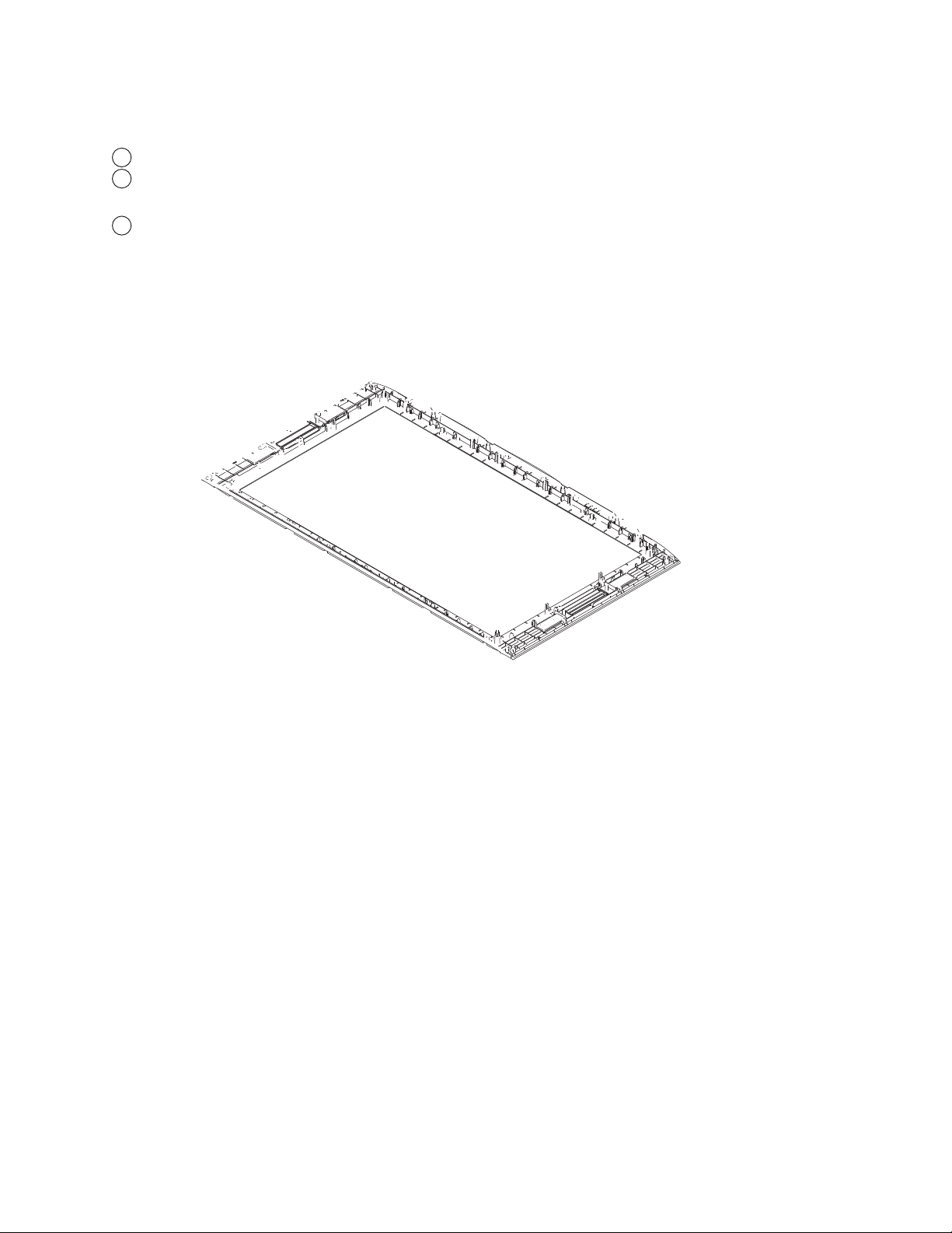
1-9. LCD PANEL REMOVAL
NOTE: The LVDS cable can only be installed one way. There is colored tape on the cable to
determine which side is attached to the TCON and which side is attached to the BM5 Board.
Disconnect 2 connectors
1
2
Remove 2 screws (KDL-40SL140 ONLY)
Remove 3 screws (KDL-46SL140 ONLY)
Remove 4 screws
3
KDL-40SL140/46SL140
1-9-1. CLEANING THE LCD PANEL
KDL-40SL140/46SL140
17
KDL-40SL140/46SL140
2
LCD Panel
1
Balancer Board
Cover
KDL-40SL140/46SL140
18
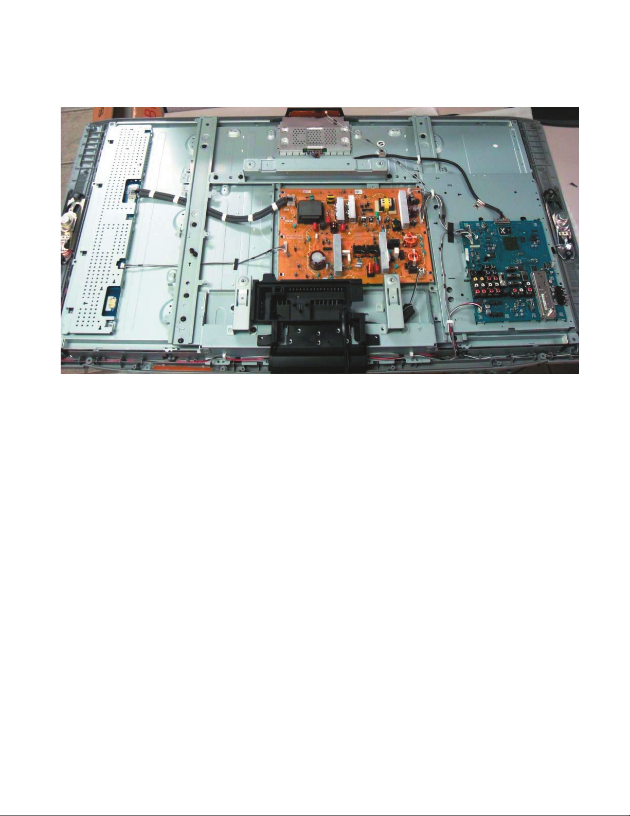
MA2F Wire Dressing 40SL [Rev: 1.0]
-!&#(!33)3
7)2%$2%33).’AND%-)
40SL140
MB609370 (2 / 10)
WIRE DRESSING
�MA2F Wire Dressing 40SL [Rev: 1.0]
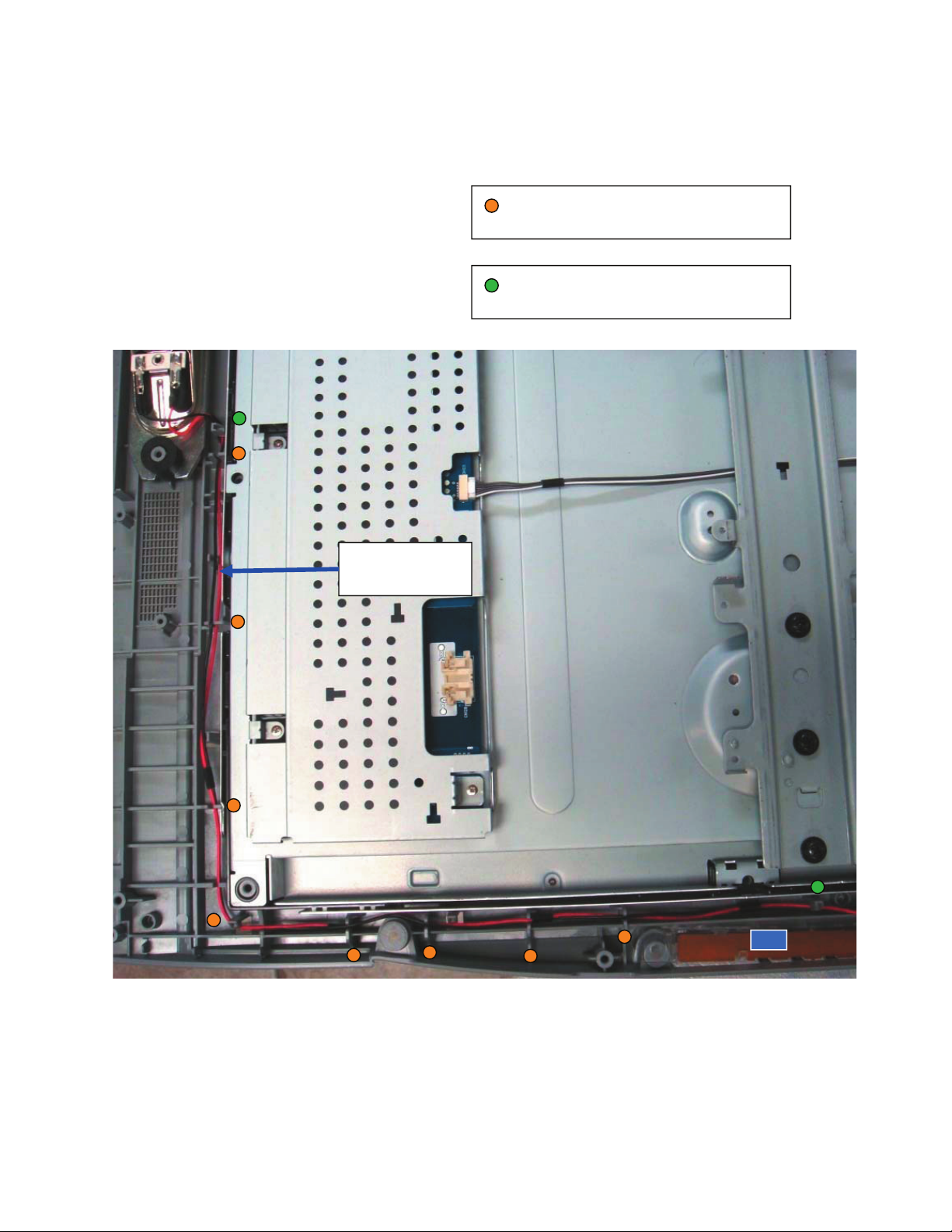
Route cable by inserting it through
Route cable by inserting it through
these 2 Hooks on Center Cab.
Speaker cable:
1-910-048-05
MB609370 (5 / 10)MB609370 (5 / 10)MB609370 (5 / 10)MB609370 (5 / 10)
these 7 Holder Ribs on Center Cab.
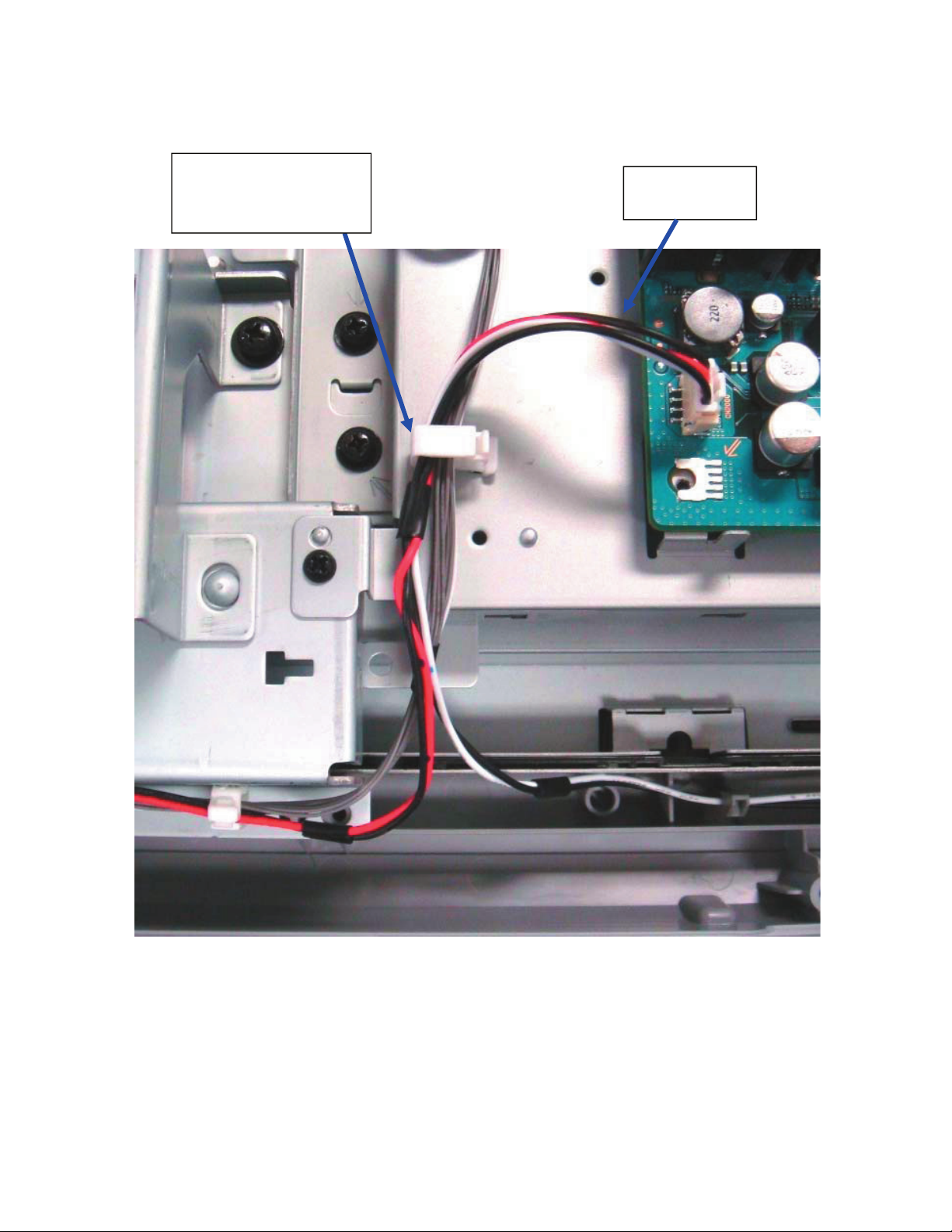
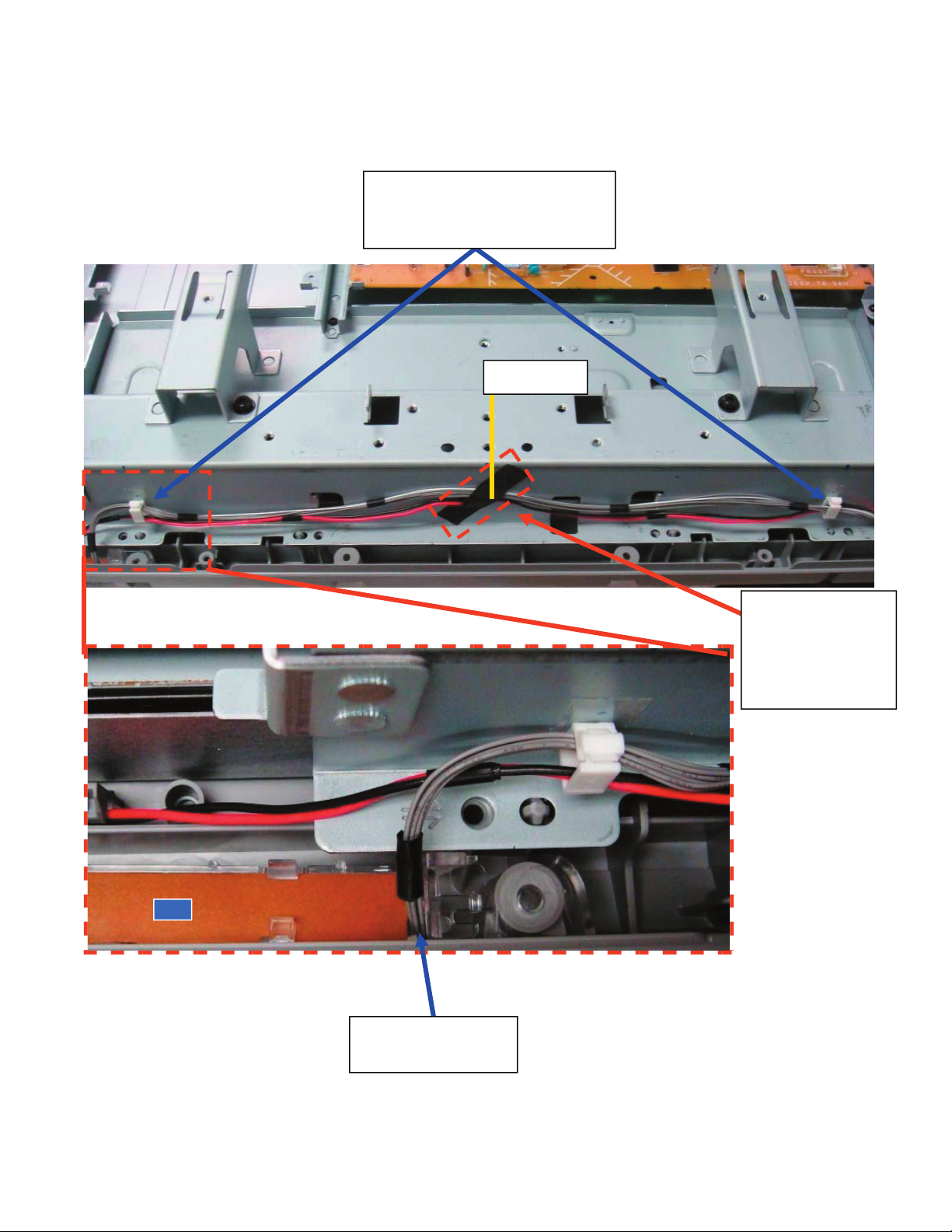
�MA2F Wire Dressing 40SL [Rev: 1.0]
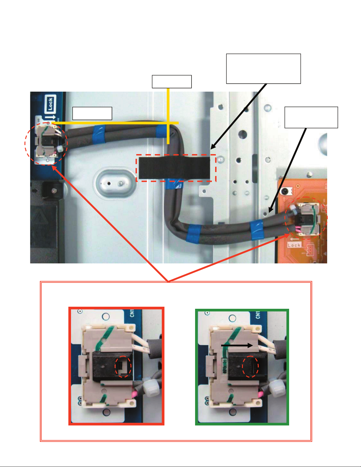
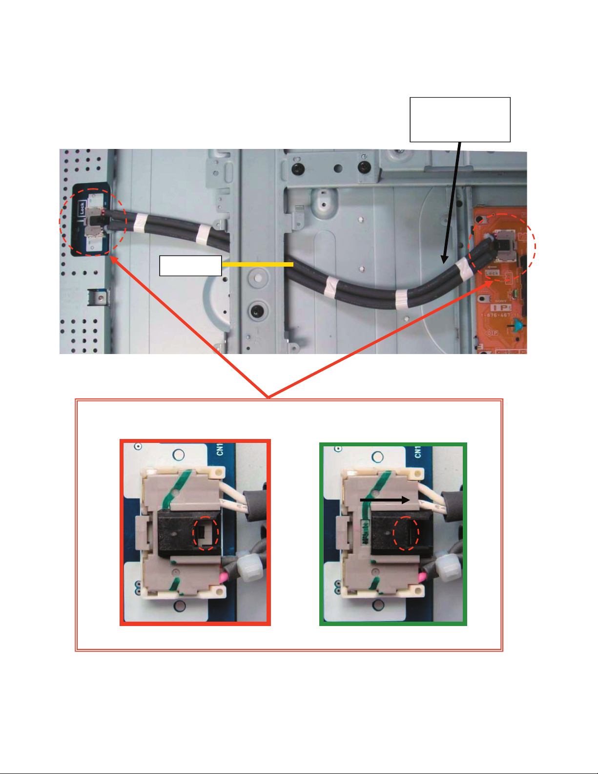
High Voltage cable:
HV cable
1-835-147-11
Fix HV cable to panel
using Himelon:
PN 4-061-565-01
CAUTION POINT:
Secure HV harness by locking the housing in place, as shown on pictures:
NG OK
Reference
Reference
MB609370 (6 / 10)MB609370 (6 / 10)MB609370 (6 / 10)MB609370 (6 / 10)MB609370 (6 / 10)
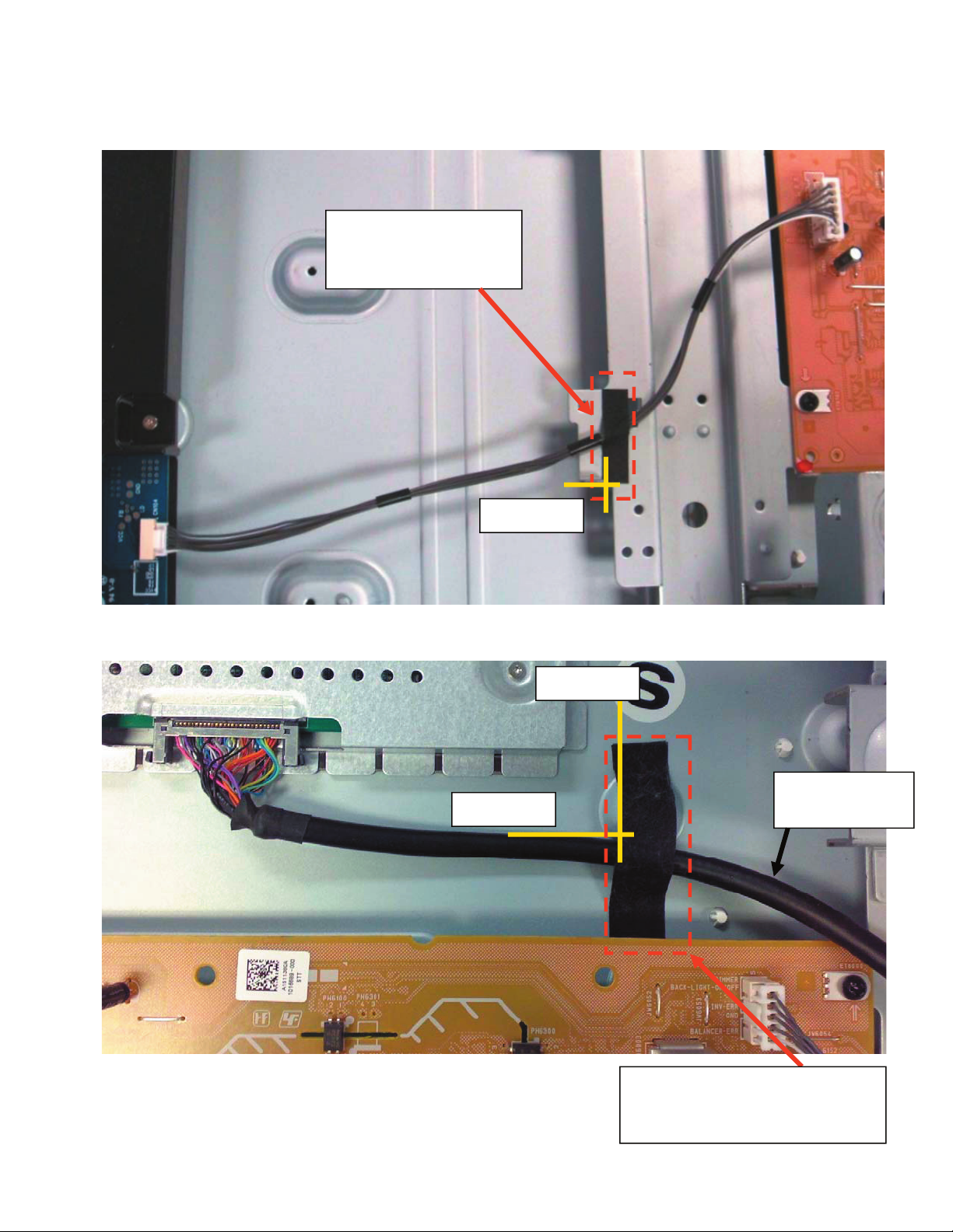
�MA2F Wire Dressing 40SL [Rev: 1.1]
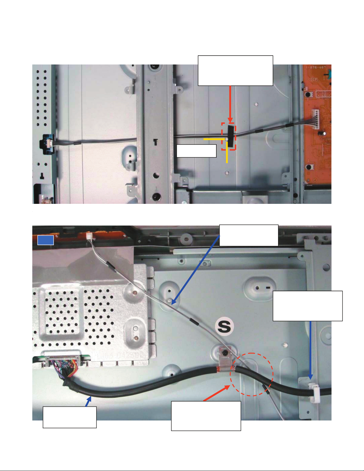
Feed Back cable:
Reference
Fix FB cable to spine
frame using Himelon:
PN 2-688-062-01
LVDS Cable:
LVDS Cable:
1-835-561-11
Fix LVDS cable to Panel using:
Himelon Tape
2-688-011-01
Reference
Reference
MB609465 (7 / 10)MB609465 (7 / 10)MB609465 (7 / 10)MB609465 (7 / 10)MB609465 (7 / 10)MB609465 (7 / 10)
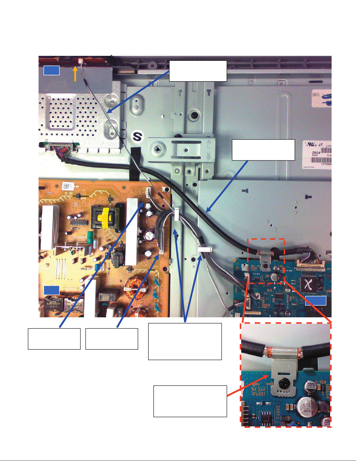
�MA2F Wire Dressing 40SL [Rev: 1.1]
H1, BL and Standby cables:
StandBy cable
1-910-044-91
BL cable
1-910-044-89
Dress LVDS cable
to this route.
H1
HM5/H1 cable:
1-910-048-08
H1 + Stanby + BL
cables through these 2
clamp holders
PN 2-650-770-11
BM5
IP5
LVDS clamp oriented
perpendicular to board
edge
MB609465 (8 / 10)MB609465 (8 / 10)MB609465 (8 / 10)MB609465 (8 / 10)MB609465 (8 / 10)MB609465 (8 / 10)MB609465 (8 / 10)
�MA2F Wire Dressing 40SL [Rev: 1.0]
Spkr cable:
1-910-048-05
HM5+Spkr cables
through this clamp holder
PN 2-650-770-21
MB609370 (9 / 10)MB609370 (9 / 10)MB609370 (9 / 10)MB609370 (9 / 10)MB609370 (9 / 10)MB609370 (9 / 10)MB609370 (9 / 10)MB609370 (9 / 10)
AC CORD
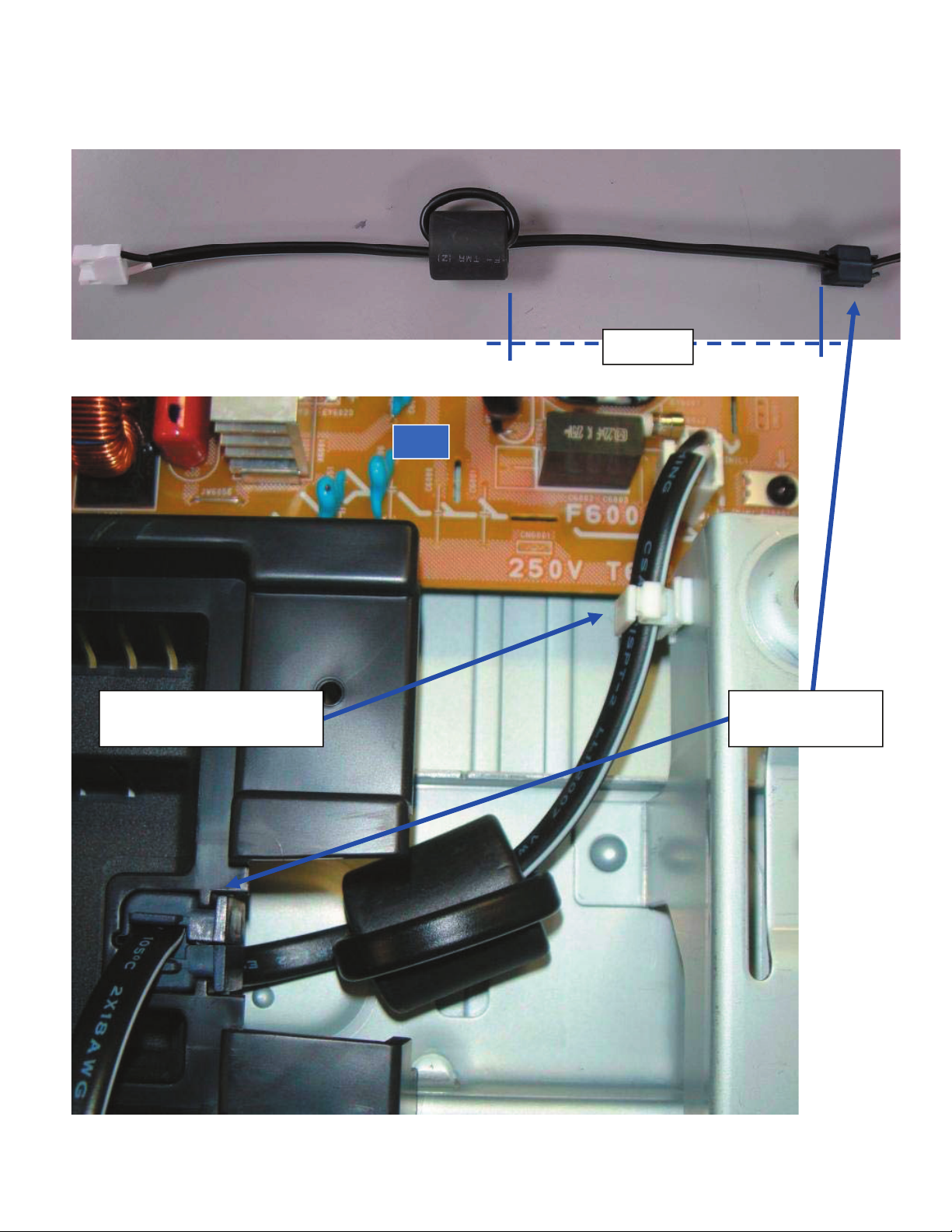
�MA2F Wire Dressing 40SL [Rev: 1.0]
AC Cord:
30 mm
AC HOLDER
4-022-115-12
AC cord through this clamp
PN 2-650-770-21
IP5
MB609370 (10 / 10)MB609370 (10 / 10)MB609370 (10 / 10)MB609370 (10 / 10)MB609370 (10 / 10)MB609370 (10 / 10)MB609370 (10 / 10)MB609370 (10 / 10)MB609370 (10 / 10)
�MA2F Wire Dressing 46SL [Rev: 1.0]
MA2F CHASSIS
WIRE DRESSING and EMI
46SL140
MB609371 (2 / 10)
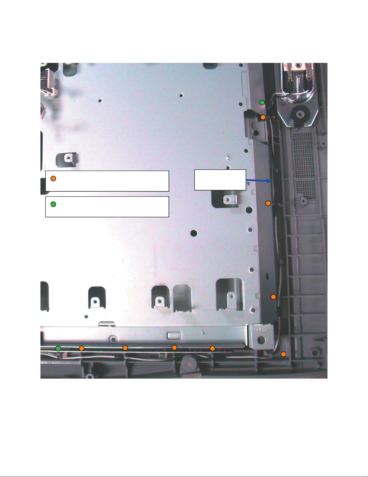
�MA2F Wire Dressing 46SL [Rev: 1.0]
HM5 cable and Speakers cable:
Route cables by inserting it through
these 8 Holder Ribs on Center Cab.
Route cables by inserting it through
these 2 Hooks on Center Cab.
Speaker cable:
1-910-048-06
HM5
MB609371 (3 / 10)MB609371 (3 / 10)
�MA2F Wire Dressing 46SL [Rev: 1.0]
Reference
HM5 and Spkr cables through
these 2 clamp holders
PN 2-650-770-21
Fix HM5 and
Spkr cables to
bottom frame
using Himelon
PN 2-688-011-01
HM5
HM5/H1 cable:
1-910-048-09
MB609371 (4 / 10)MB609371 (4 / 10)MB609371 (4 / 10)
�MA2F Wire Dressing 46SL [Rev: 1.0]
Speaker cable:
1-910-048-06
Route cable by inserting it through
these 8 Holder Ribs on Center Cab.
Route cable by inserting it through
these 2 Hooks on Center Cab.
MB609371 (5 / 10)MB609371 (5 / 10)MB609371 (5 / 10)MB609371 (5 / 10)
�MA2F Wire Dressing 46SL [Rev: 1.0]
High Voltage cable:
Reference
HV cable
1-835-148-11
Route as shown
CAUTION POINT:
Secure HV harness by locking the housing in place, as shown on pictures:
NG OK
MB609371 (6 / 10)MB609371 (6 / 10)MB609371 (6 / 10)MB609371 (6 / 10)MB609371 (6 / 10)
�MA2F Wire Dressing 46SL [Rev: 1.0]
Feedback cable:
Reference
Fix FB cable to spine
frame using Himelon:
PN 2-688-062-01
LVDS and H1 cables:
LVDS cable through
this clamp holder
PN 2-650-770-11
HM5/H1 cable:
1-910-048-09
H1 cable goes under
LVDS cable and
before metal clamp
H1
LVDS Cable:
1-835-560-11
MB609371 (7 / 10)MB609371 (7 / 10)MB609371 (7 / 10)MB609371 (7 / 10)MB609371 (7 / 10)MB609371 (7 / 10)
 Loading...