

Sony KDL-40SL130, KDL-32SL130 Service Manual
HISTORY INFORMATION FOR THE FOLLOWING MANUAL:
SERVICE MANUAL
MODEL NAME REMOTE COMMANDER DESTINATION
KDL-32SL130
KDL-40SL130
RM-YD018 US
RM-YD018 US
WAX3
CHASSIS
ORIGINAL MANUAL ISSUE DATE: 5/2007
: UPDATED ITEM
☛
REVISION DATE SUBJECT
5/2007 No revisions or updates are applicable at this time.
6/2007 Reissue entire manual to correct model name.
10/2007 Corrected P/N for KDL-32SL130 ETC-Inverter MT Board. Replaced Page 93.
Added Battery Cover P/N. Replaced Page 125.
LCD DIGITAL COLOR TELEVISION
9-883-752-03
Self Diagnosis
Supported model
SERVICE MANUAL
MODEL NAME REMOTE COMMANDER DESTINATION
KDL-32SL130
KDL-40SL130
RM-YD018 US
RM-YD018 US
WAX3
CHASSIS
9-883-752-03
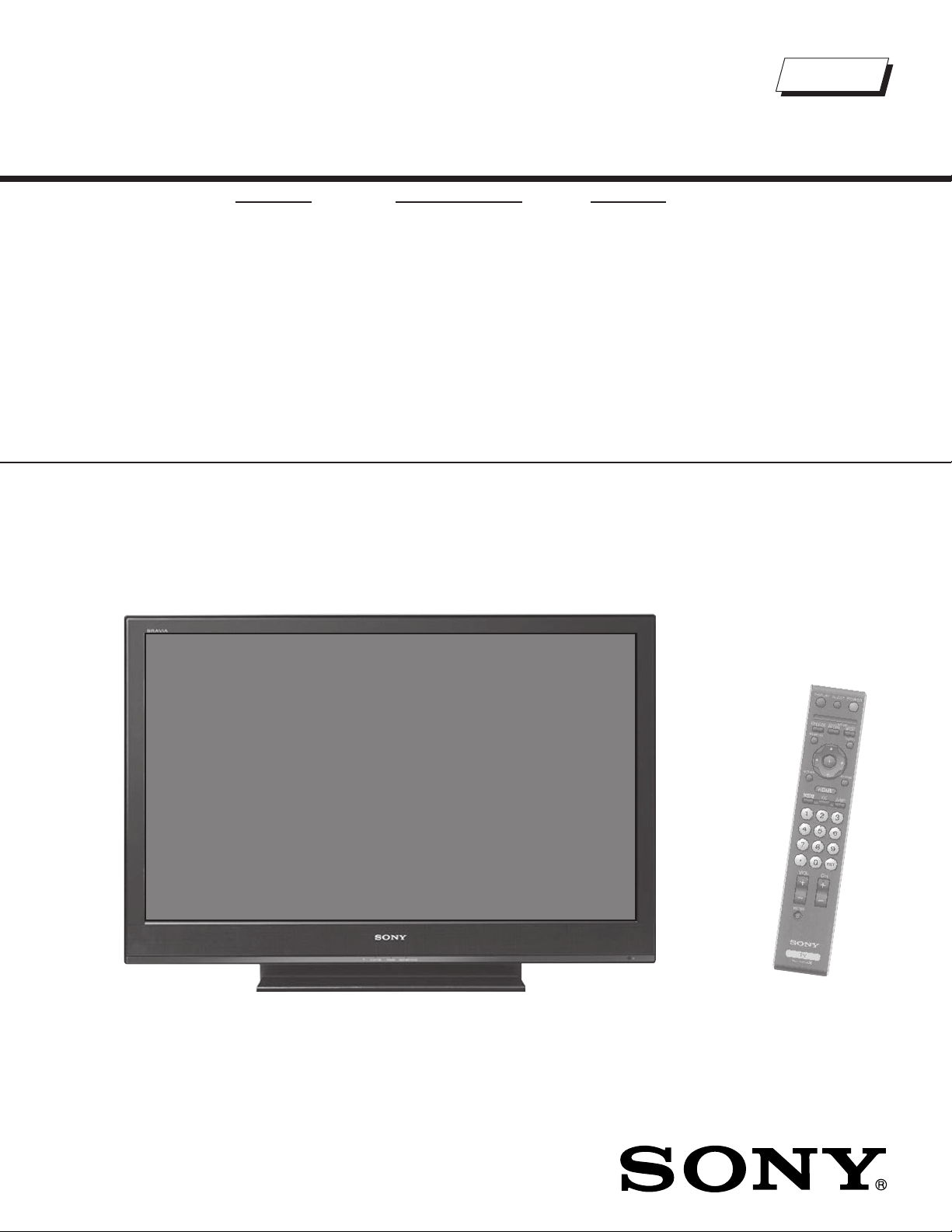
KDL-40SL130 RM-YD018
LCD DIGITAL COLOR TELEVISION

KDL-32SL130/40SL130
TABLE OF CONTENTS
SECTION TITLE PAGE SECTION TITLE PAGE
Specifi cations ................................................................................. 4
Warnings and Cautions .................................................................. 6
Safety-Related Component Warning .............................................. 7
Safety Check-Out ........................................................................... 9
Self-Diagnostic Function ............................................................... 10
SECTION 1: DISASSEMBLY ............................................................... 12
1-1. Rear Cover Removal ............................................................ 12
1-2. H1 Board Removal ............................................................... 12
1-3. Stand Assembly and VESA Arm Assembly Removal
(KDL-32SL130 Only) ............................................................ 13
1-4. Stand Assembly and VESA Arm Assembly Removal
(KDL-40SL130 Only) ............................................................ 13
1-5. U1 Board, Side Terminal and Side Jack Holder Removal .... 14
1-6. BU1 Board Removal ............................................................ 14
1-7. Speaker, H3 Board, and H4 Board Removal ....................... 15
1-8. G1H Board (Power Unit) and G1 Bracket Removal
(KDL-32SL130 Only) ............................................................ 15
1-9. G3 Board (Power Unit) and D1 Board Removal
(KDL-40SL130 Only) ............................................................ 16
1-9-1. Replacing the Inverter Connector Assembly
(KDL-40SL130 Only) ............................................... 16
1-10. AC Inlet Removal (KDL-32SL130 Only) ............................... 17
1-11. AC Inlet Removal (KDL-40SL130 Only) ............................... 17
1-12. LCD Panel, LED and Guide Light Removal
(KDL-32SL130 Only) ............................................................ 18
1-13. LCD Panel, LED and Guide Light Removal
(KDL-40SL130 Only) ............................................................ 19
1-14. Inverter Board Removal ....................................................... 20
Wire Dressing ............................................................................... 21
KDL-32SL130 Only .............................................................. 21
KDL-40SL130 Only .............................................................. 37
SECTION 2: SERVICE ADJUSTMENTS ............................................. 55
2-1. Using the Remote Commander for Electrical Adjustments .. 55
2-2. Accessing Service Adjustment Mode ................................... 55
2-3. Viewing the Service Menus .................................................. 55
2-4. Using the Remote Commander to View Service Data ......... 56
2-4-1. Changing Service Data ............................................ 56
2-4-2. Exiting Service Mode ............................................... 56
2-5. Verifying Service Data Changes .......................................... 57
2-6. Resetting to Factory Defaults ............................................... 57
SECTION 3: DIAGRAMS ..................................................................... 58
3-1. Circuit Boards Location ........................................................ 58
3-2. Printed Wiring Boards and
Schematic Diagrams Information ......................................... 59
3-3. Block Diagram ...................................................................... 60
Signal Flow Diagram ............................................................ 60
Connection Diagram (KDL-32SL130 Only) .......................... 61
Connection Diagram (KDL-40SL130 Only) .......................... 62
3-4. Schematics and Supporting Information .............................. 63
BU1 Board Schematic Diagram (1 of 12) ............................. 63
BU1 Board Schematic Diagram (2 of 12) ............................. 64
BU1 Board Schematic Diagram (3 of 12) ............................. 65
BU1 Board Schematic Diagram (4 of 12) ............................. 66
BU1 Board Schematic Diagram (5 of 12) ............................. 67
BU1 Board Schematic Diagram (6 of 12) ............................. 68
BU1 Board Schematic Diagram (7 of 12) ............................. 69
BU1 Board Schematic Diagram (8 of 12) ............................. 70
BU1 Board Schematic Diagram (9 of 12) ............................. 71
BU1 Board Schematic Diagram (10 of 12) ........................... 72
BU1 Board Schematic Diagram (11 of 12) ........................... 73
BU1 Board Schematic Diagram (12 of 12) ........................... 74
D1 Board Schematic Diagram (KDL-40SL130 Only) ........... 76
G1H Board Schematic Diagram (Power Supply)
(KDL-32SL130 Only) ............................................... 79
G3 Board Schematic Diagram (Power Supply)
(KDL-40SL130 Only) ............................................... 80
H1 Board Schematic Diagram .............................................. 82
H3 Board Schematic Diagram .............................................. 84
H4 Board Schematic Diagram .............................................. 86
U1 Board Schematic Diagram .............................................. 88
3-5. Semiconductors ................................................................... 90
SECTION 4: EXPLODED VIEWS ........................................................ 91
4-1. Rear Cover and Stand Assembly ........................................ 91
4-2. Chassis ................................................................................ 92
4-3. Bezel Assembly and LCD Panel ......................................... 93
4-5. Connectors (KDL-32SL130 Only) ....................................... 94
4-6. Connectors (KDL-40SL130 Only) ...................................... 95
4-7. Speakers ............................................................................. 96
SECTION 5: ELECTRICAL PARTS LIST ............................................ 97
APPENDIX A: ENCRYPTION KEY COMPONENTS ..........................A-1
KDL-32SL130/40SL130
3
SPECIFICATIONS
KDL-32SL130/40SL130
Power Requirements
120V-240V AC, 50/60Hz
Video (IN) 1/2/3
S Video (4-Pin Mini DIN (VIDEO 1/2 Only)
Y: 1.0 Vp-p, 75 ohms unbalanced, sync negative
C: 0.286 Vp-p (Burst signal), 75 ohms
Video
1.0 Vp-p, 75ohms unbalanced, sync negative
Audio
500 mVrms (100% modulation)
Impedance:47 kilohms
COMPONENT IN 1/2
YP
(Component Video)
BPR
Y:1.0 Vp-p, 75 ohms unbalanced, sync negative
PB:0.7 Vp-p, 75 ohms
PR:0.7 Vp-p, 75 ohms
Signal format: 480i, 480p, 720p, 1080i, 1080p
AUDIO
500 mVrms (100% modulation)
Impedance: 47 kilohms
HDMI IN 1/2:
HDMI: Video:480i, 480p, 720p, 1080i, 1080p
Audio: Two channel linear PCM 32, 44.1 and
48 kHz, 16, 20 and 24 bits
AUDIO: (HDMI IN 2 only) 500 mVrms (100% modulation)
Impedance: 47 kilohms
AUDIO OUT:
500 mVrms (100% modulation)
More than 1 Vrms at the maximum volume setting (Variable)
More than 500 mVrms (Fixed)
PC IN:
D-sub 15-pin, analog RGB, 0.7 Vp-p, 75 ohms, positive
PC AUDIO INPUT:
Stereo mini jack, 0.5 Vrms, 1 kilohm
HEADPHONES:
Stereo mini jack
Impedance: 16 ohms
Trademark Information
“BRAVIA” and , S-Force,
BRAVIA Theatre Sync, and DMe
trademarks or registered marks of Sony Corporation.
Blu-ray Disc is a trademark.
“XMB”, “XrossMediaBar” and “PS3” are
trademarks of Sony Corporation and/or
Sony Computer Entertainment Inc.
HDMI, the HDMI logo and High-Definition Multimedia Interface are
trademarks or registered trademarks of HDMI Licensing, LLC.
Macintosh is a trademark licensed to Apple Computer, Inc., registered in
the U.S.A and other countries.
Manufactured under license from Dolby
Laboratories. “Dolby” and the double-D symbol are
trademarks of Dolby Laboratories.
As an ENERGY STAR
determined that this product meets the ENERGY ST AR
guidelines for energy efficiency.
ENERGY STAR
KDL-32SL130/40SL130
x
are
This TV incorporates High-Definition
Multimedia Interface (HDMI™) technology.
®
Partner, Sony Corporation has
®
is a U.S. registered mark.
®
Design and specifi cations are subject to change without notice.
4
Power Consumption
in use
in standby
Speaker Output (W)
mm
Dimensions (W x H x D)
with stand
mm
Dimensions (W x H x D)
without stand
mm
Mass
with stand
without stand
KDL-32SL130 KDL-40SL130
158W 180W
Less than 0.1W
10W x 10W
42 x 150 mm 55 x 150 mm
in
11/16
1
x 6 in 2
1/4
x 6 in
790 x 577 x 214 mm 981 x 692 x 265 mm
in
31
1/8
x 22
3/4
x 8
1/2
in 38
5/8
x 27
1/4
790 x 530 x 100 mm 981 x 643 x 110 mm
in
kg
31
1/8
x 20
7/8
x 4 in 38
5/8
x 25
17 kg 25 kg
3/8
lbs 38 lbs 56 lbs
kg
14.5 kg 21 kg
lbs 32 lbs 47 lbs
x 10
x 4
3/8
1/2
KDL-32SL130/40SL130
in
in
Television system
NTSC American TV Standard
ATSC (8VSB terrestrial) ATSC compliant 8VSB
QAM on cable: ANSI/SCTE 07 2000
Channel coverage
Analog Digital
Terrestrial 2-69 2-69
Cable 1-125 1-135
Antenna
75-ohm external terminal for VHF/UHF
Panel System
LCD (Liquid Crystal Display) Panel
Display Resolution (horizontal x vertical):
1,366 dots x 768 lines
Screen Size (measured diagonally)
31.5 inches (KDL-32SL130 Only)
40 inches (KDL-40SL130 Only)
Supplied Accessories
Remote Commander RM-YD018
Two Size AA (R6) Batteries
AC Power Cord
HD15-HD15 Cable
Suport Belt, Securing Screw, and Wood Screw
Cable Holder
Operating Instructions
Quick Setup Guide
Warranty Card
Optional Accessories
Headphones Plug Adapter
Connecting Cables
Wall-Mount Bracket
SU-WL500
TV Stand
RHT-G800
KDL-32SL130/40SL130
5
KDL-32SL130/40SL130
WARNINGS AND CAUTIONS
CAUTION
These servicing instructions are for use by qualifi ed service personnel only. To reduce the risk of electric shock, do not perform any servicing other
than that contained in the operating instructions unless you are qualifi ed to do so.
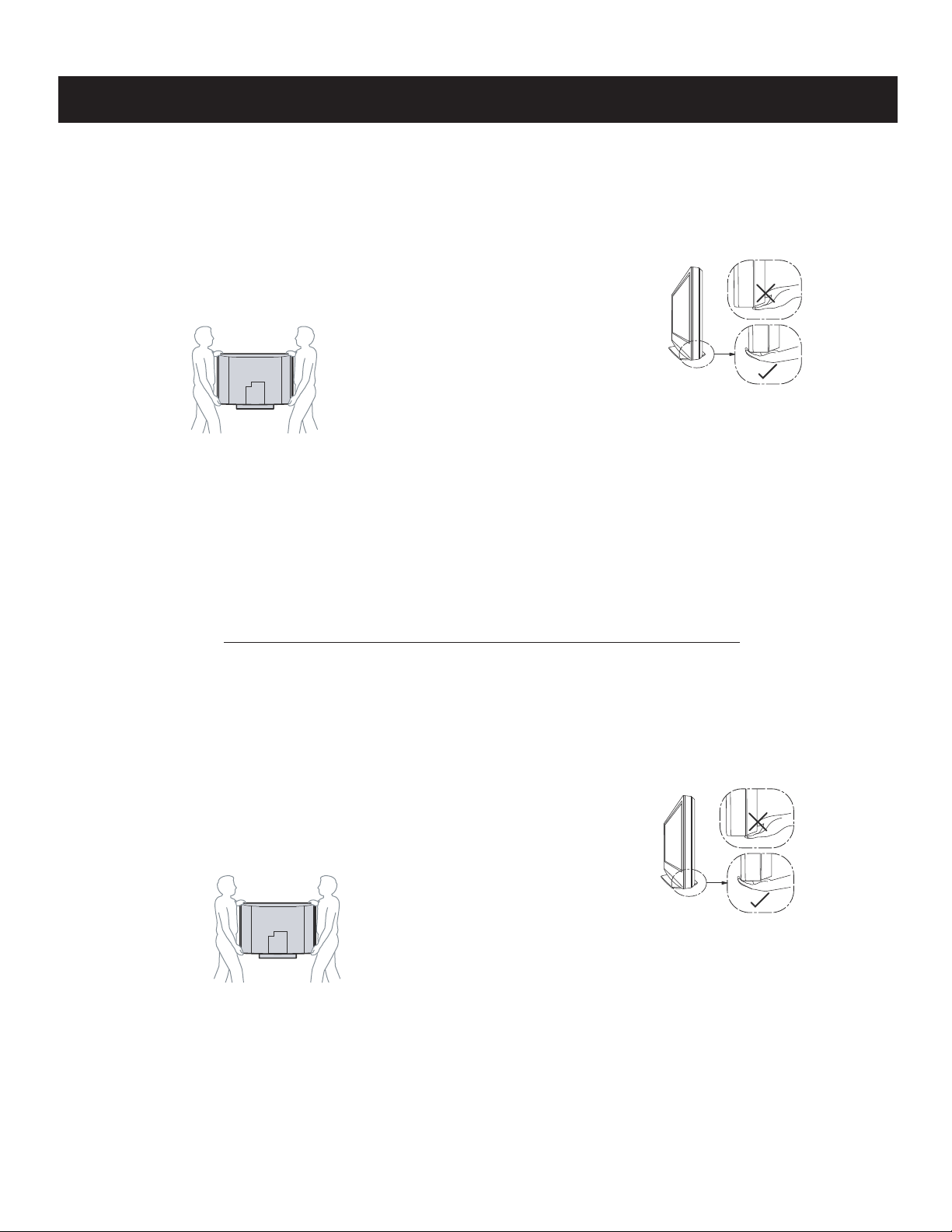
CARRYING THE TV
To avoid dropping the TV and causing serious injury, be sure to follow
these guidelines:
s Before carrying the TV, disconnect all cables.
s Carrying the large size TV requires two or more people.
s When you carry the TV, place your hand as illustrated and hold it
securely. Do not put stress on the LCD panel.
KDL-32SL130/KDL-40SL130
s When lifting or moving the TV, hold it firmly from the bottom. Place
your palm directly under the panel.
s When carrying, do not subject the TV to shocks or vibration, or
excessive force.
WARNING!!
An isolation transformer should be used during any service to avoid possible shock hazard, because of live chassis. The chassis of this receiver is
directly connected to the ac power line.
! SAFETY-RELATED COMPONENT WARNING!!
Components identifi ed by shading and ! mark on the schematic diagrams, exploded views, and in the parts list are critical for safe operation. Replace
these components with Sony parts whose part numbers appear as shown in this manual or in supplements published by Sony. Circuit adjustments that
are critical for safe operation are identifi ed in this manual. Follow these procedures whenever critical components are replaced or improper operation is
suspected.
ATTENTION!!
Ces instructions de service sont à l’usage du personnel de service qualifi é seulement. Pour prévenir le risque de choc électrique, ne pas faire
l’entretien autre que celui contenu dans le Mode d’emploi à moins que vous soyez qualifi é faire ainsi.
POUR TRANSPORTER LE TÉLÉVISEUR
Assurez-vous de suivre ces consignes pour éviter de laisser tomber le
téléviseur et de provoquer des blessures graves :
s Avant de transporter le téléviseur, débranchez tous les câbles.
s Le transport du téléviseur doit être effectué par au moins deux
personnes.
s Lorsque vous le transportez, placez vos mains tel que cela est illustré
et tenez solidement l’appareil. N’appliquez pas de pression sur
l’écran ACL.
KDL-32SL130/KDL-40SL130
s Lorsque vous levez ou déplacez le téléviseur, assurez-vous de tenir
solidement de la base. Placez la paume des mains directement sous
le panneau.
s Lorsque vous transportez le téléviseur, ne le soumettez pas à des
chocs ou vibrations, ni à une force excessive.
Afi n d’eviter tout risque d’electrocution provenant d’un chássis sous tension, un transformateur d’isolement doit etre utilisé lors de tout dépannage. Le
chássis de ce récepteur est directement raccordé à l’alimentation du secteur.
! ATTENTION AUX COMPOSANTS RELATIFS A LA SECURITE!!
Les composants identifi es par une trame et par une marque ! sur les schemas de principe, les vues explosees et les listes de pieces sont d’une
importance critique pour la securite du fonctionnement. Ne les remplacer que par des composants Sony dont le numero de piece est indique dans le
present manuel ou dans des supplements publies par Sony. Les reglages de circuit dont l’importance est critique pour la securite du fonctionnement
sont identifi es dans le present manuel. Suivre ces procedures lors de chaque remplacement de composants critiques, ou lorsqu’un mauvais
fonctionnement suspecte.
KDL-32SL130/40SL130
6
SAFETY-RELATED COMPONENT WARNING
KDL-32SL130/40SL130
There are critical components used in LCD color TVs that are important for safety. These components are identifi ed with shading and
mark on the schematic diagrams and the electrical parts list. It is essential that these critical parts be replaced only with the part number
specifi ed in the electrical parts list to prevent electric shock, fi re, or other hazard.
NOTE: Do not modify the original design without obtaining written permission from the manufacturer or you will void the original parts and
labor guarantee.
!
USE CAUTION WHEN HANDLING THE LCD PANEL
When repairing the LCD panel, be sure you are grounded by using a wrist band.
When installing the LCD panel on a wall, the LCD panel must be secured using the 4 mounting holes on the rear cover.
To avoid damaging the LCD panel:
do not press on the panel or frame edge to avoid the risk of electric shock.
do not scratch or press on the panel with any sharp objects.
do not leave the module in high temperatures or in areas of high humidity for an extended period of time.
do not expose the LCD panel to direct sunlight.
avoid contact with water. It may cause a short circuit within the module.
disconnect the AC adapter when replacing the backlight (CCFL) or inverter circuit.
(High voltage occurs at the inverter circuit at 650Vrms.)
always clean the LCD panel with a soft cloth material.
use care when handling the wires or connectors of the inverter circuit. Damaging the wires may cause a short.
protect the panel from ESD to avoid damaging the electronic circuit (C-MOS).
LEAKAGE CURRENT HOT CHECK CIRCUIT
KDL-32SL130/40SL130
7
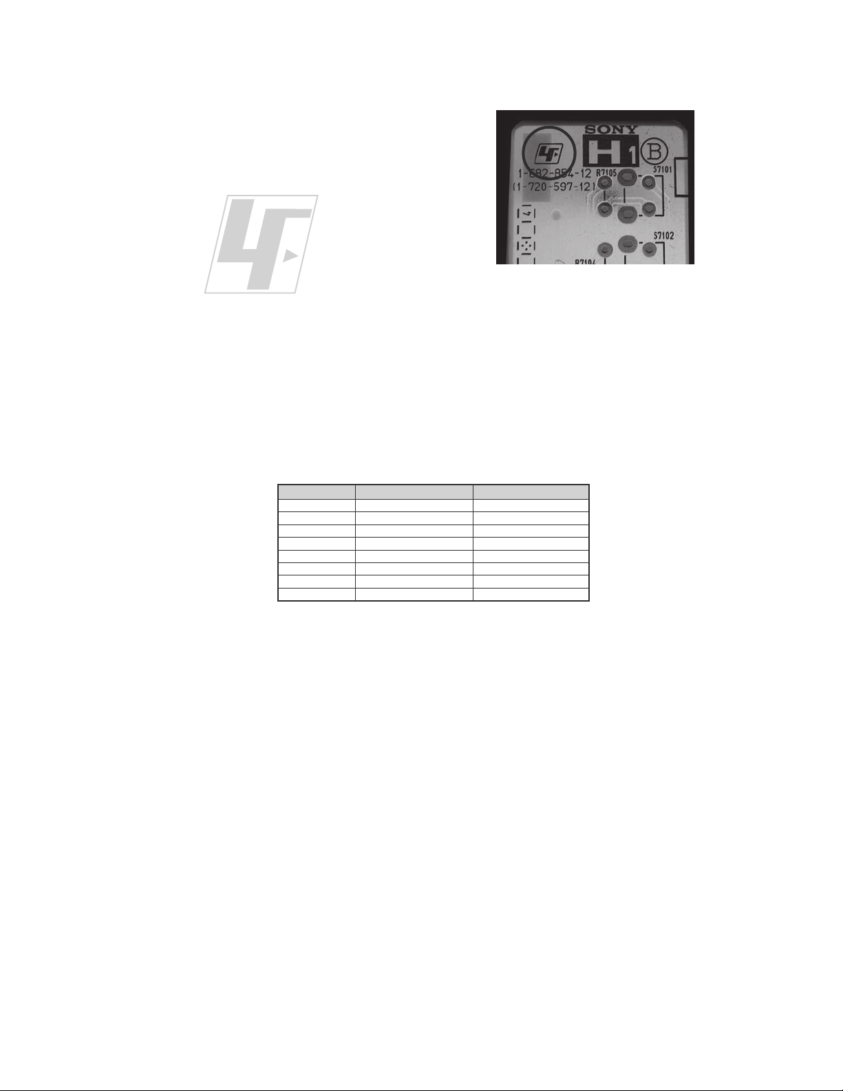
The circuit boards used in these models have been processed using
Lead Free Solder. The boards are identified by the LF logo located
close to the board designation e.g. H1 etc [ see example ]. The
servicing of these boards requires special precautions to be taken as
outlined below.
KDL-32SL130/40SL130
example 1
It is strongly recommended to use Lead Free Solder material in order to guarantee optimal quality of new solder joints.
Lead Free Solder is available under the following part numbers :
rebmuntraP retemaiD skrameR
91-500-046-7mm3.0gK52.0
02-500-046-7mm4.0gK05.0
12-500-046-7mm5.0gK05.0
22-500-046-7mm6.0gK52.0
32-500-046-7mm8.0gK00.1
42-500-046-7mm0.1gK00.1
52-500-046-7mm2.1gK00.1
62-500-046-7mm6.1gK00.1
Due to the higher melting point of Lead Free Solder the soldering iron tip temperature needs to be set to 370 degrees centigrade.
This requires soldering equipment capable of accurate temperature control coupled with a good heat recovery characteristics.
For more information on the use of Lead Free Solder, please refer to
http://www .sony-training.com
KDL-32SL130/40SL130
8
SAFETY CHECK-OUT
KDL-32SL130/40SL130
After correcting the original service problem, perform the following
safety checks before releasing the set to the customer:
1. Check the area of your repair for unsoldered or poorly soldered
connections. Check the entire board surface for solder splashes and
bridges.
2. Check the interboard wiring to ensure that no wires are “pinched” or
touching high-wattage resistors.
3. Check that all control knobs, shields, covers, ground straps, and
mounting hardware have been replaced. Be absolutely certain that
you have replaced all the insulators.
4. Look for unauthorized replacement parts, particularly transistors,
that were installed during a previous repair. Point them out to the
customer and recommend their replacement.
5. Look for parts which, though functioning, show obvious signs of
deterioration. Point them out to the customer and recommend their
replacement.
6. Check the line cords for cracks and abrasion. Recommend the
replacement of any such line cord to the customer.
7. Check the antenna terminals, metal trim, “metallized” knobs, screws,
and all other exposed metal parts for AC leakage. Check leakage as
described below.
The AC leakage from any exposed metal part to earth ground and
from all exposed metal parts to any exposed metal part having a
return to chassis, must not exceed 0.5 mA (500 microamperes).
Leakage current can be measured by any one of three methods.
1. A commercial leakage tester, such as the Simpson 229 or RCA
WT-540A. Follow the manufacturers’ instructions to use these
instructions.
2. A battery-operated AC milliampmeter. The Data Precision 245
digital multimeter is suitable for this job.
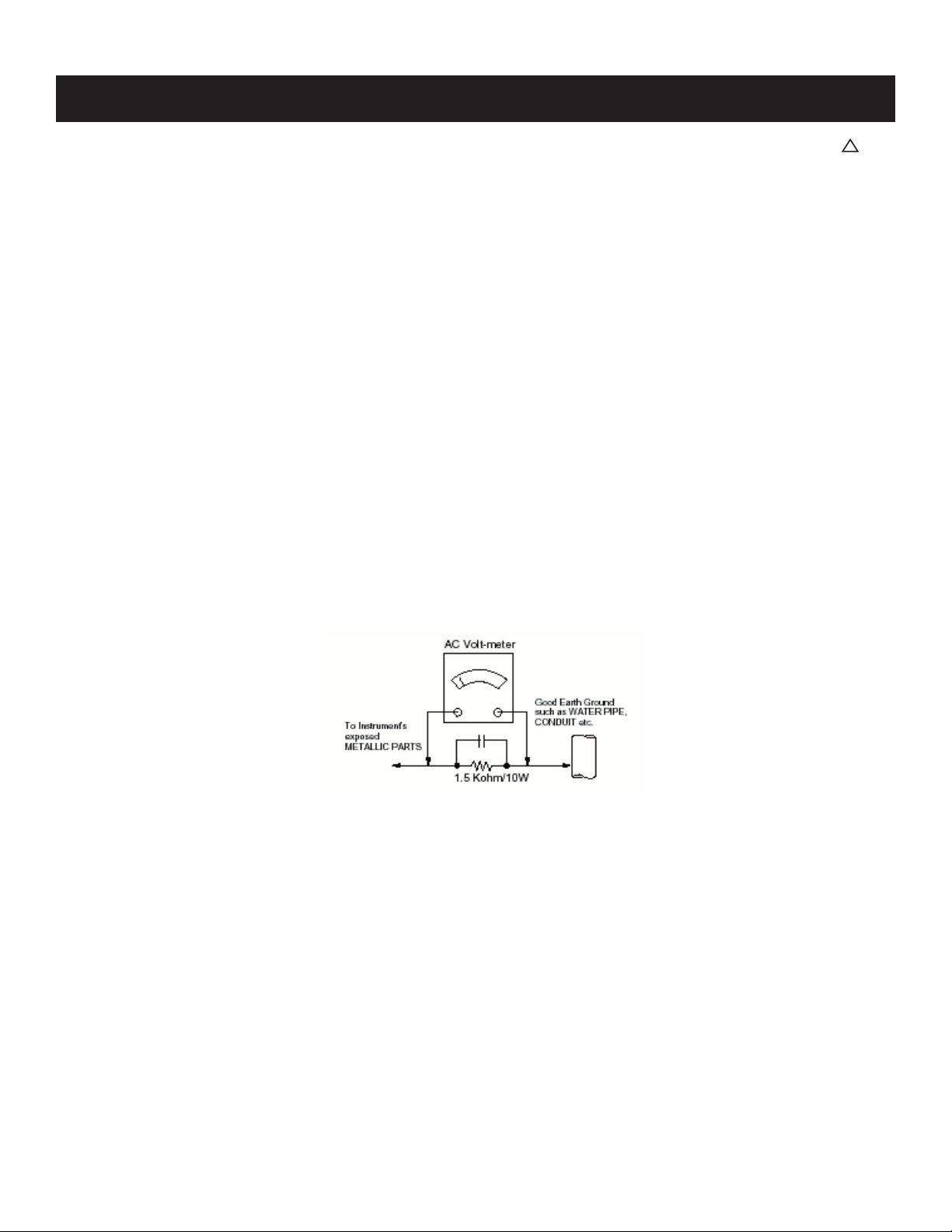
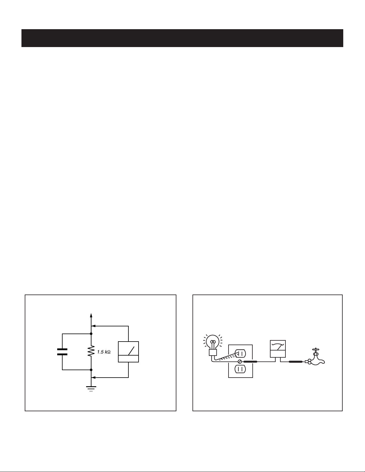
3. Measuring the voltage drop across a resistor by means of a VOM
or battery-operated AC voltmeter. The “limit” indication is 0.75
V, so analog meters must have an accurate low voltage scale.
The Simpson’s 250 and Sanwa SH-63TRD are examples of
passive VOMs that are suitable. Nearly all battery-operated digital
multimeters that have a 2 VAC range are suitable (see Figure A).
How to Find a Good Earth Ground
A cold-water pipe is a guaranteed earth ground; the cover-plate
retaining screw on most AC outlet boxes is also at earth ground. If the
retaining screw is to be used as your earth ground, verify that it is at
ground by measuring the resistance between it and a cold-water pipe
with an ohmmeter. The reading should be zero ohms.
If a cold-water pipe is not accessible, connect a 60- to 100-watt
trouble- light (not a neon lamp) between the hot side of the receptacle
and the retaining screw. Try both slots, if necessary, to locate the hot
side on the line; the lamp should light at normal brilliance if the screw
is at ground potential (see Figure B).
Leakage Test
0.15 μF
Figure A. Using an AC voltmeter to check AC leakage. Figure B. Checking for earth ground.
To Exposed Metal
Parts on Set
Earth Ground
AC
Voltmeter
(0.75V)
Trouble Light
AC Outlet Box
Ohmmeter
Cold-water Pipe
KDL-32SL130/40SL130
9
KDL-32SL130/40SL130
g
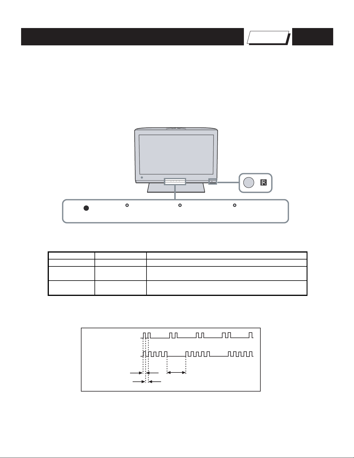
SELF-DIAGNOSTIC FUNCTION
The units in this manual contain a self-diagnostic function. If an error occurs, the STANDBY LED indicator will automatically begin to fl ash. The number
of times the LED fl ashes translates to a probable source of the problem. A defi nition of the STANDBY LED fl ash indicators is listed in the instruction
manual for the user’s knowledge and reference. If an error symptom cannot be reproduced, the Remote Commander can be used to review the failure
occurrence data stored in memory to reveal past problems and how often these problems occur.
1. Diagnostic Test Indicators
When an error occurs, the STANDBY LED indicator will fl ash a set number of times to indicate the possible cause of the problem. If there is more than
one error, the indicator will identify the fi rst of the problem areas.
Control Buttons
Self Diagnosis
Supported model
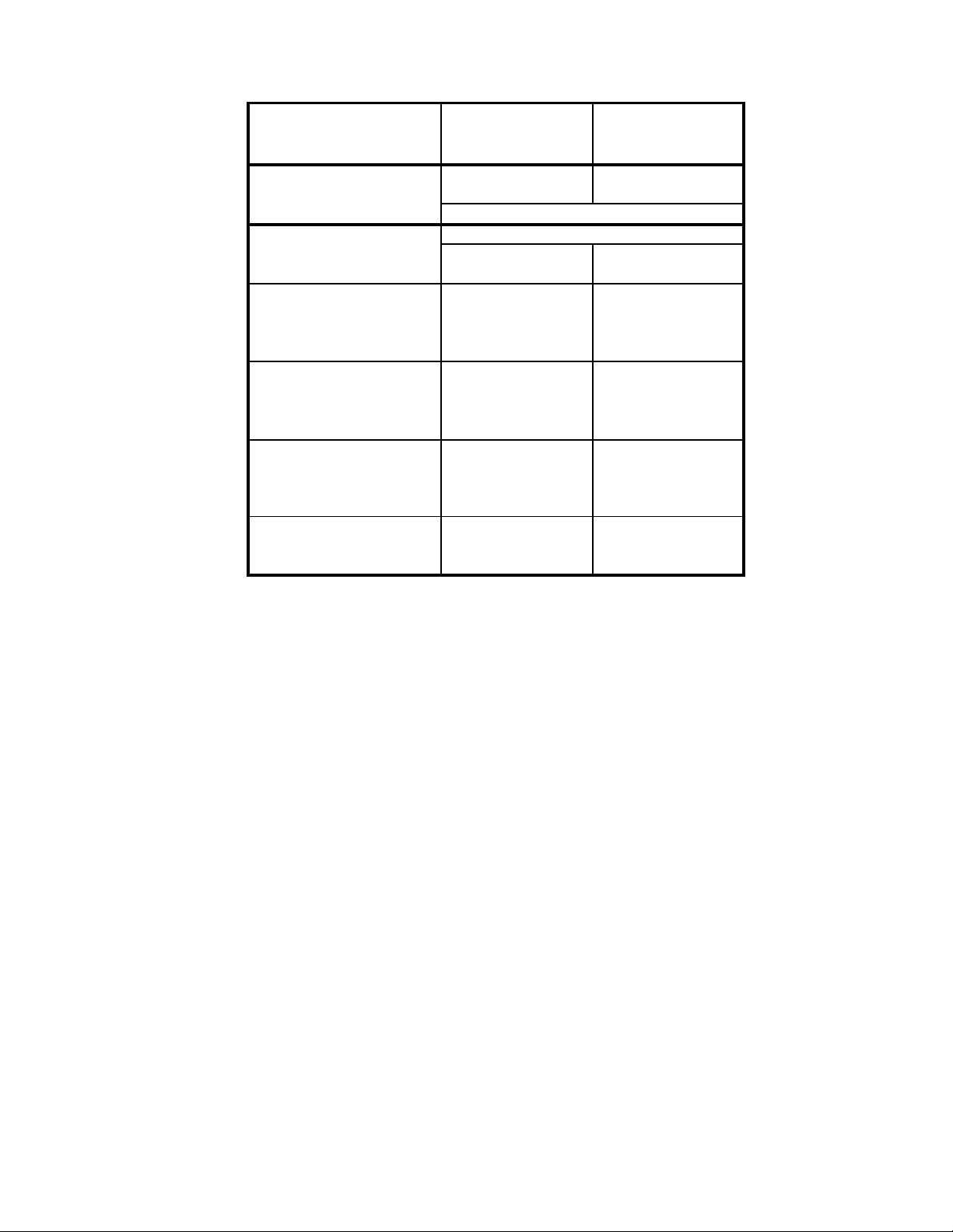
Description of LED Indictors
LED LED Type Description
POWER LED Green LED
STANDBY LED Red LED
PIC OFF/TIMER
LED
Display of STANDBY LED Flash Count
Amber/Green LED
LED ON 0.3 sec.
LED OFF 0.3 sec.
PIC OFF/TIMER STANDBY POWER
* Light is green when the TV set is on
* Lights is red when the TV is in PC standby mode
* Blinks red when indicating the TV may need servicing
* Li
ht is green when the Picture Offfeature is activated
* Light is amber when the timer is set
2 times
5 times
LED OFF
3 sec.
KDL-32SL130/40SL130
10
KDL-32SL130/40SL130
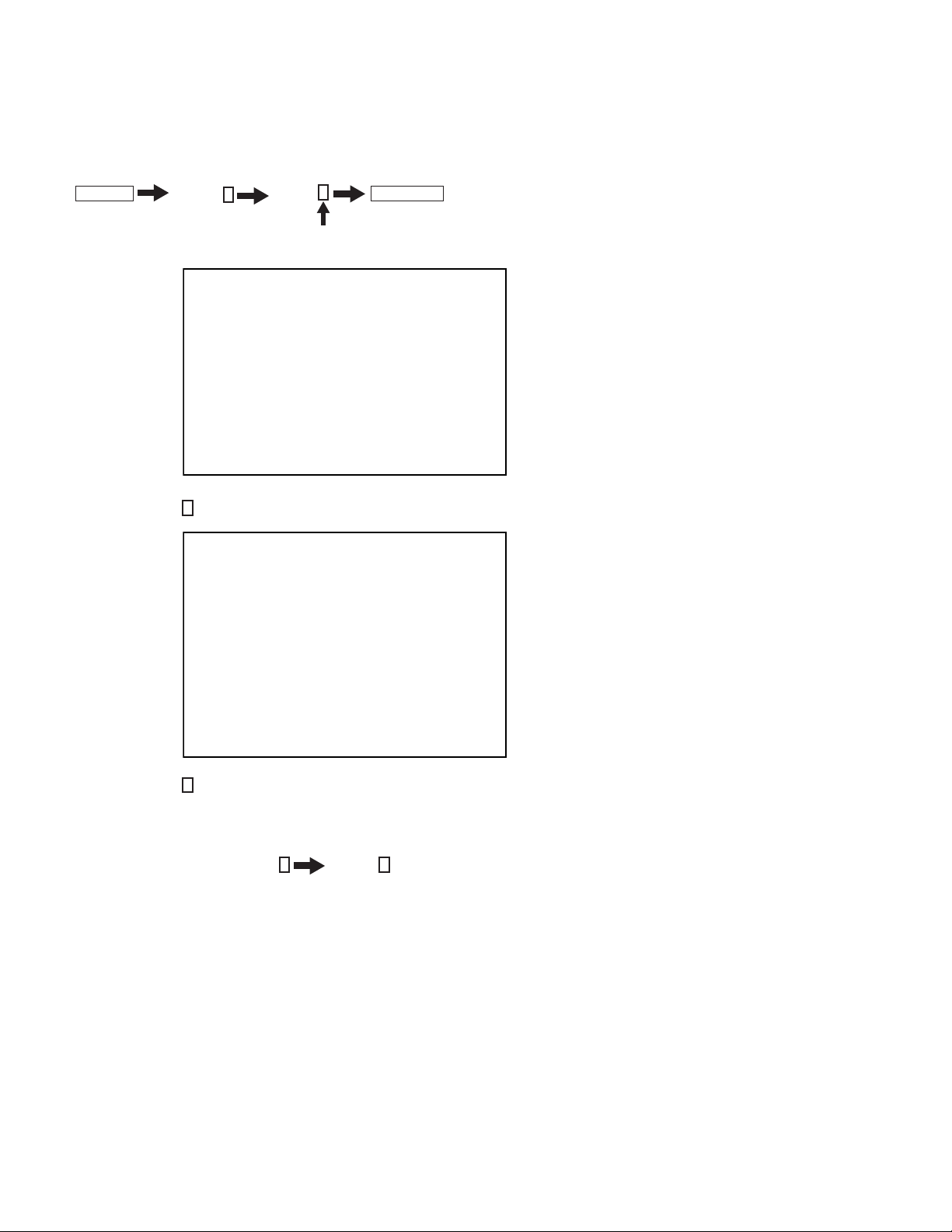
Viewing the Self Check Diagnostic List
1. TV must be in standby mode. (Power off).
2. Press the following buttons on the Remote Commander within a second of each other:
DISPLAY
The Self Check list displays. This differs from accessing Service Adjustments.
Results for all of the following diagnostic items are displayed on screen. No error has occurred if the screen displays a “0”.
Channel 5 Volume -
TV POWER
.
SELF CHECK PAGE 1
002 MAIN_POWER 01
003 DC_ALERT1 00
Í 1 indicates an error was detected
Í 0 indicates no error was detected
004 DC_ALERT2 00
005 DC_ALERT3 00
006 BACK_LIGHT 00
013 BACK_LIGHT_BALANCE 00
00009-00019-00009
3. Press the Channel 1 button on the Remote Commander to go to Page 2 of the Self Check list.
SELF CHECK PAGE 2
008 SP_PROT 01
007 TEMP 00
011 TRIDENT_IC 00
010 DIGITAL 00
009 NA 00
007 HFR_OVERHEAT 00
012 HFR_ERROR
00009-00019-00009
4. Press the Channel
Clearing the Self Check Diagnostic List
1. In Service Mode, press the Channel 8 Channel 0.
4
button on the Remote Commander to go back to Page 1 of the Self Check list.
KDL-32SL130/40SL130
11
SECTION 1: DISASSEMBLY
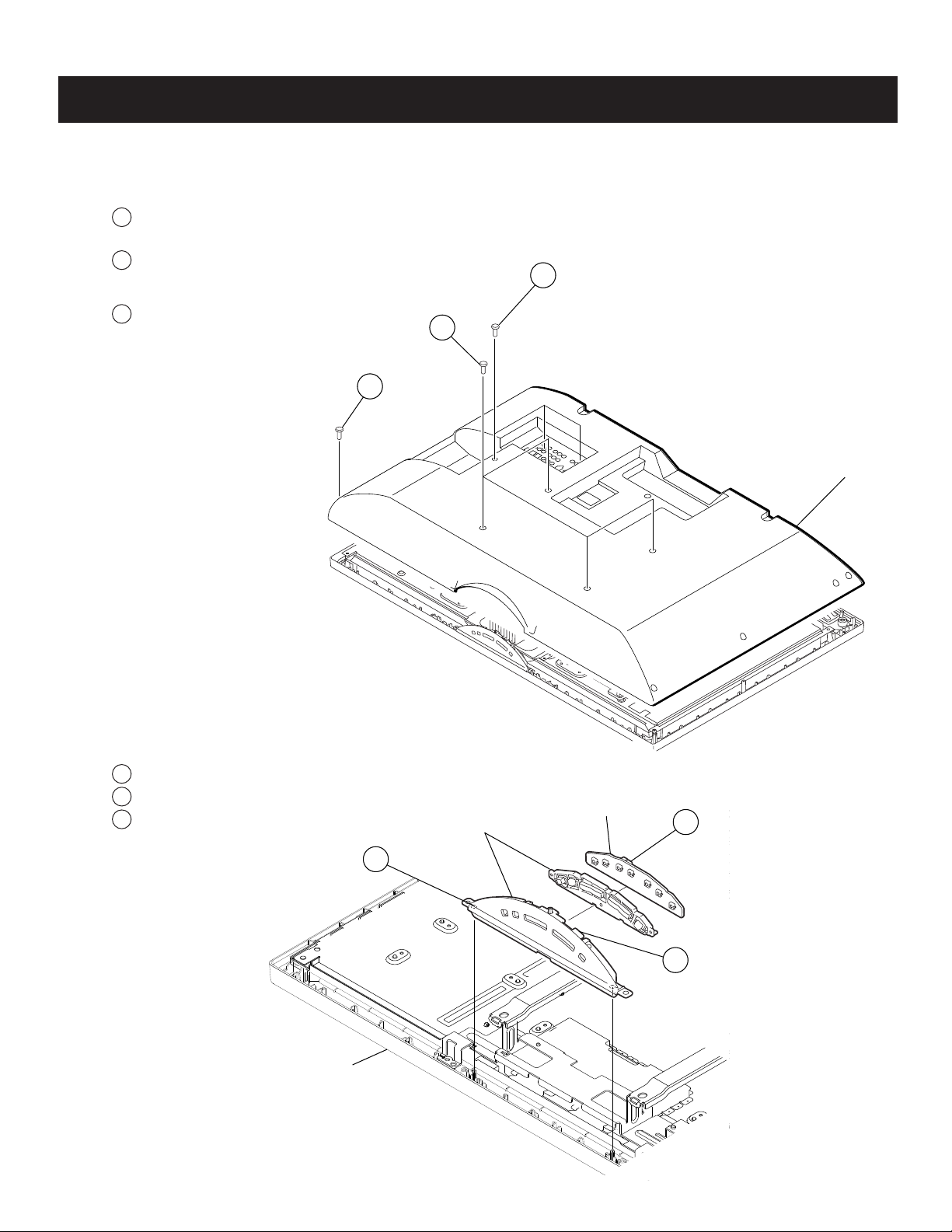
1-1. REAR COVER REMOVAL
1
Remove 3 screws from Terminals, +BVTP 3X12
TYPE2 IT-3
2
Remove 2 screws (KDL-32SL130),
4 screws (KDL-40SL130)
from Rear Cover arm positions, +PSW M5X16
3
Remove 14 screws (KDL-32SL130), 15 screws
(KDL-40SL130), from Rear Cover, +BVTP2 4X16
3
KDL-32SL130/40SL130
1
2
Rear Cover
1-2. H1 BOARD REMOVAL
1
Remove from bezel
2
Disconnect one connector
3
Release hooks and remove H1 Board
Bezel Assembly
Multi Button Assembly
1
H1 Board
2
3
KDL-32SL130/40SL130
12
KDL-32SL130/40SL130
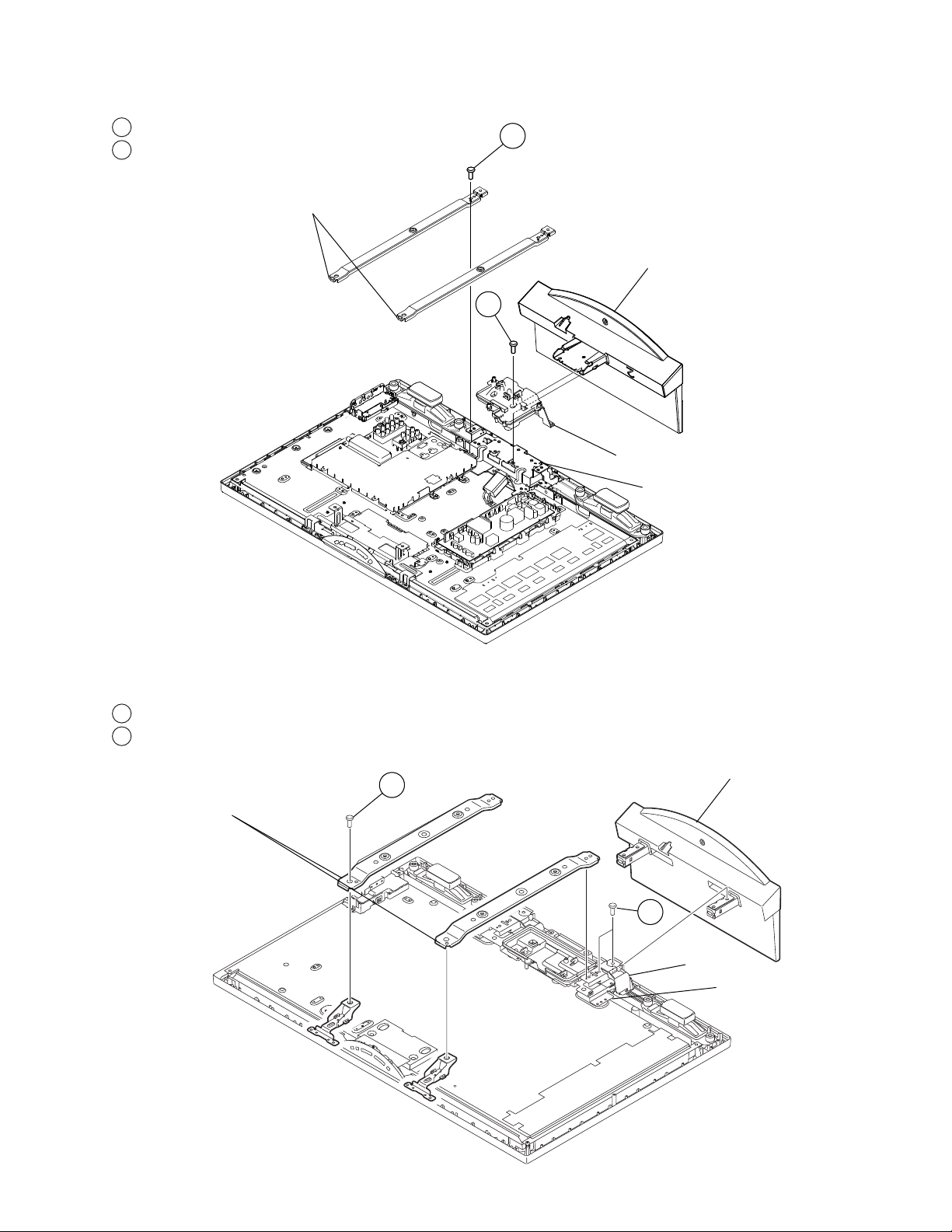
1-3. STAND ASSEMBLY AND VESA ARM ASSEMBLY REMOVAL (KDL-32SL130 ONLY)
1
Remove 2 screws from bottom of Arms, +PSW M5X16
2
Remove 3 screws from bottom bracket and Stand,
+PSW M5X16
VESA Arm Assembly
1
Stand Assembly
2
Under Cover
Bottom Bracket
1-4. STAND ASSEMBLY AND VESA ARM ASSEMBLY REMOVAL (KDL-40SL130 ONLY)
1
Remove 4 screws from bottom of Arms, +PSW M5X16
2
Remove 4 screws from bottom bracket and Stand, +PSW
M5X16
1
VESA Arm Assembly
Stand Assembly
2
Under Cover
Bottom Bracket
KDL-32SL130/40SL130
13
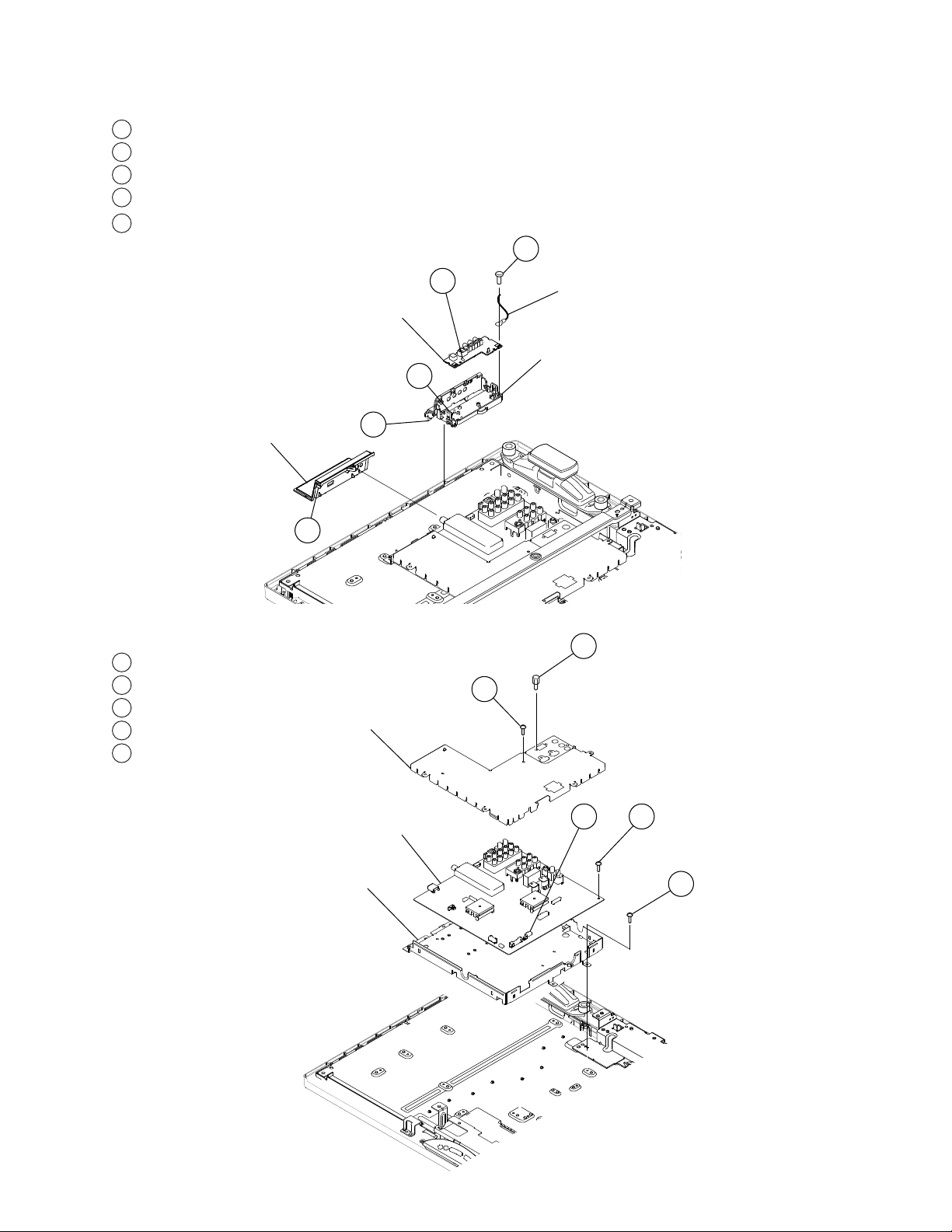
1-5. U1 BOARD, SIDE TERMINAL AND SIDE JACK HOLDER REMOVAL
1
Disconnect one connector
2
Remove one screw, +BVTP 3X12 TYPE2 IT-3
3
Release hooks and remove U1 Board.
4
Remove Side Terminal from Bezel.
5
Release hooks to remove Side Jack Holder from BU1 bottom
shield.
2
KDL-32SL130/40SL130
Side Jack Holder
1-6. BU1 BOARD REMOVAL
1
Remove 2 screws, +PSW M3X5
2
Remove 2 screws, HEX
3
Disconnect 5 connectors
4
Remove 7 screws, +BVST 3X8
5
Remove 5 screws, +PSW M3X5
U1 Board
5
BU1 Top Shield
1
3
4
1
Wire Assembly
Side Terminal
2
KDL-32SL130/40SL130
BU1 Board
BU1 Bottom Shield
43
5
14
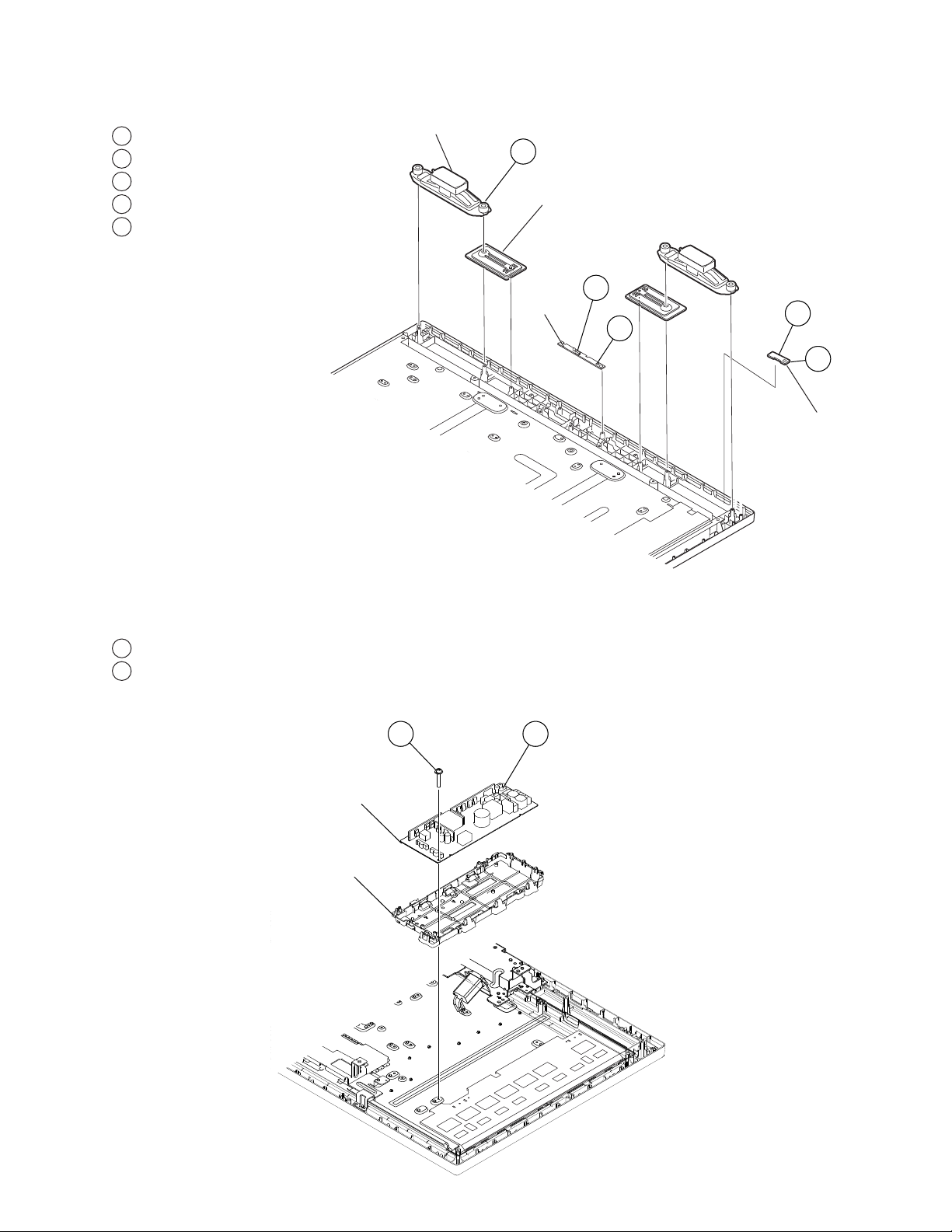
1-7. SPEAKER, H3 BOARD, AND H4 BOARD REMOVAL
KDL-32SL130/40SL130
1
Slide out Speaker and Baffl e from Bezel
2
Disconnect one connector
3
Release hooks and remove H3 Board
4
Disconnect one connector
5
Release hooks and remove H4 Board
Under Cover
1
Baffle Assembly
(KDL-40SL130 Only)
2
H3 Board
3
4
5
H4 Board
1-8. G1H BOARD (POWER UNIT) AND G1 BRACKET REMOVAL (KDL-32SL130 ONLY)
1
Remove 4 screws, +PSW 3SG
2
Disconnect 3 connectors
1 2
Power Unit
G1 Bracket
KDL-32SL130/40SL130
15
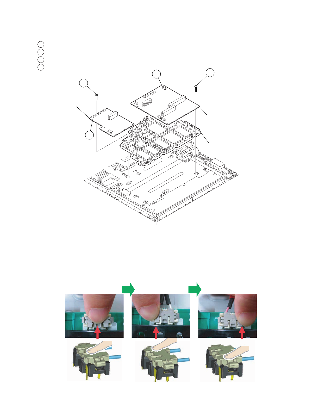
1-9. G3 BOARD (POWER UNIT) AND D1 BOARD REMOVAL (KDL-40SL130 ONLY)
1
Disconnect 6 connectors
2
Remove 4 screws, +PSW 3SG
3
Disconnect 4 connectors
4
Remove 4 screws, +PSW 3SG
4
D1 Board
3
1
2
G3 Board
G3 Bracket
KDL-32SL130/40SL130
1-9-1. REPLACING THE INVERTER CONNECTOR ASSEMBLY (KDL-40SL130 ONLY)
Use the following procedure to confirm that the Inverter connector is securely attached
to the board.
1
After inserting the connector
into the board, push the
middle section of the inverter
connector to confirm it
is securely connected.
Push the right section of
23
the inverter connector and
confirm it is securely
connected.
Push the left section of
the inverter connector and
confirm it is securely
connected.
KDL-32SL130/40SL130
16
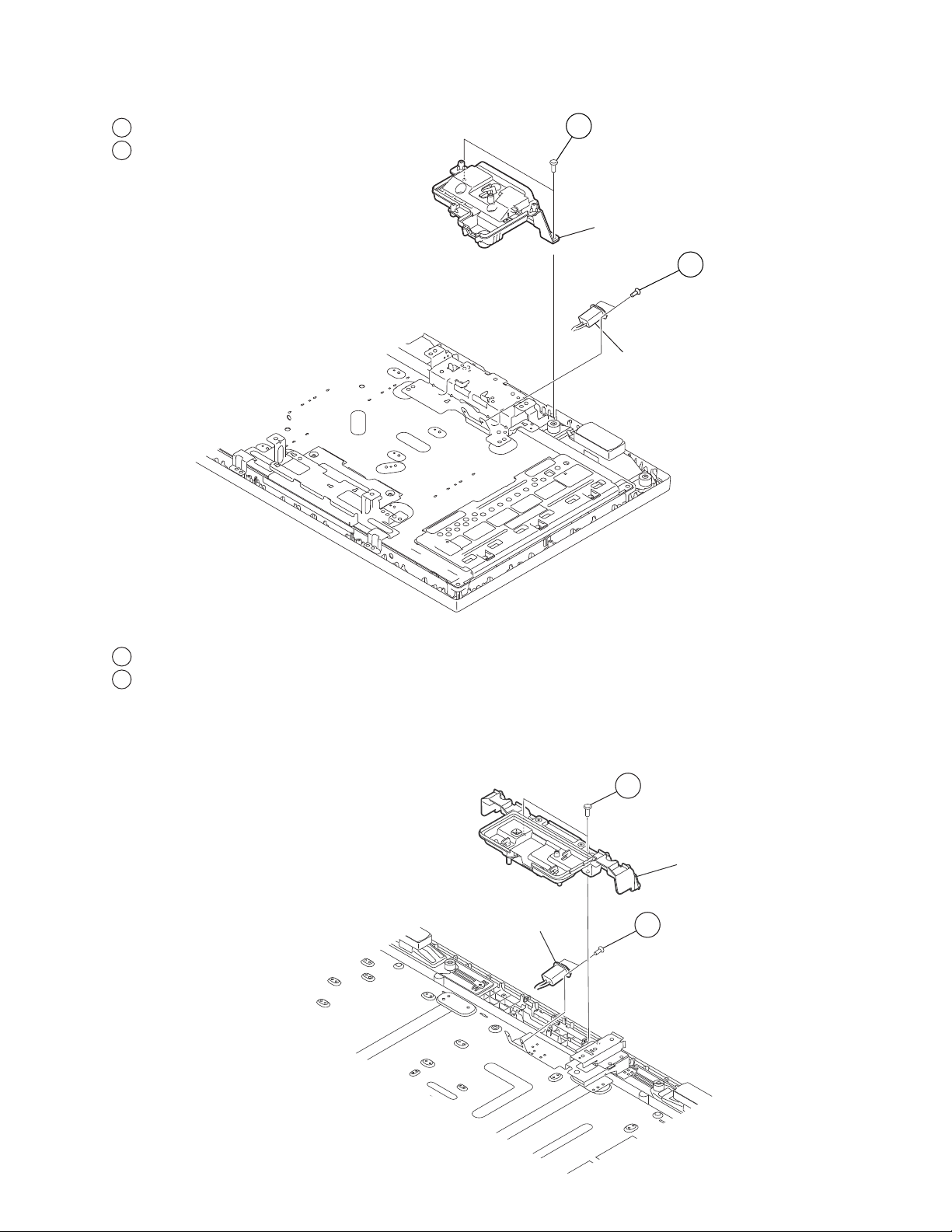
1-10. AC INLET REMOVAL (KDL-32SL130 ONLY)
r
KDL-32SL130/40SL130
1
Remove 2 screws, +BVTP2 4X16
2
Remove 2 screws, +KTT 3X10
1
Under Cover
2
AC Inlet
1-11. AC INLET REMOVAL (KDL-40SL130 ONLY)
1
Remove 2 screws, +BVTP2 4X16
2
Remove 2 screws, +KTT 3X10
AC Inlet
1
Under Cove
2
KDL-32SL130/40SL130
17
1-12. LCD PANEL, LED AND GUIDE LIGHT REMOVAL (KDL-32SL130 ONLY)
1
Remove 2 screws, +PSW M4X8
2
Remove 2 screws, +BVTP2 4X16
3
Remove 2 screws, +BVTP2 4X16
4
Remove 2 screws, +PSW M4X8
5
Remove 3 screws, +BVTP2 4X16
6
Remove ornamental panel and slide out LED Guide and Light Guide
3
4
Bottom Bracket
KDL-32SL130/40SL130
Top Bracket
1
2
Bezel
5
LED Guide
6
LCD Panel
Guide Light
Ornamental Panel
KDL-32SL130/40SL130
18

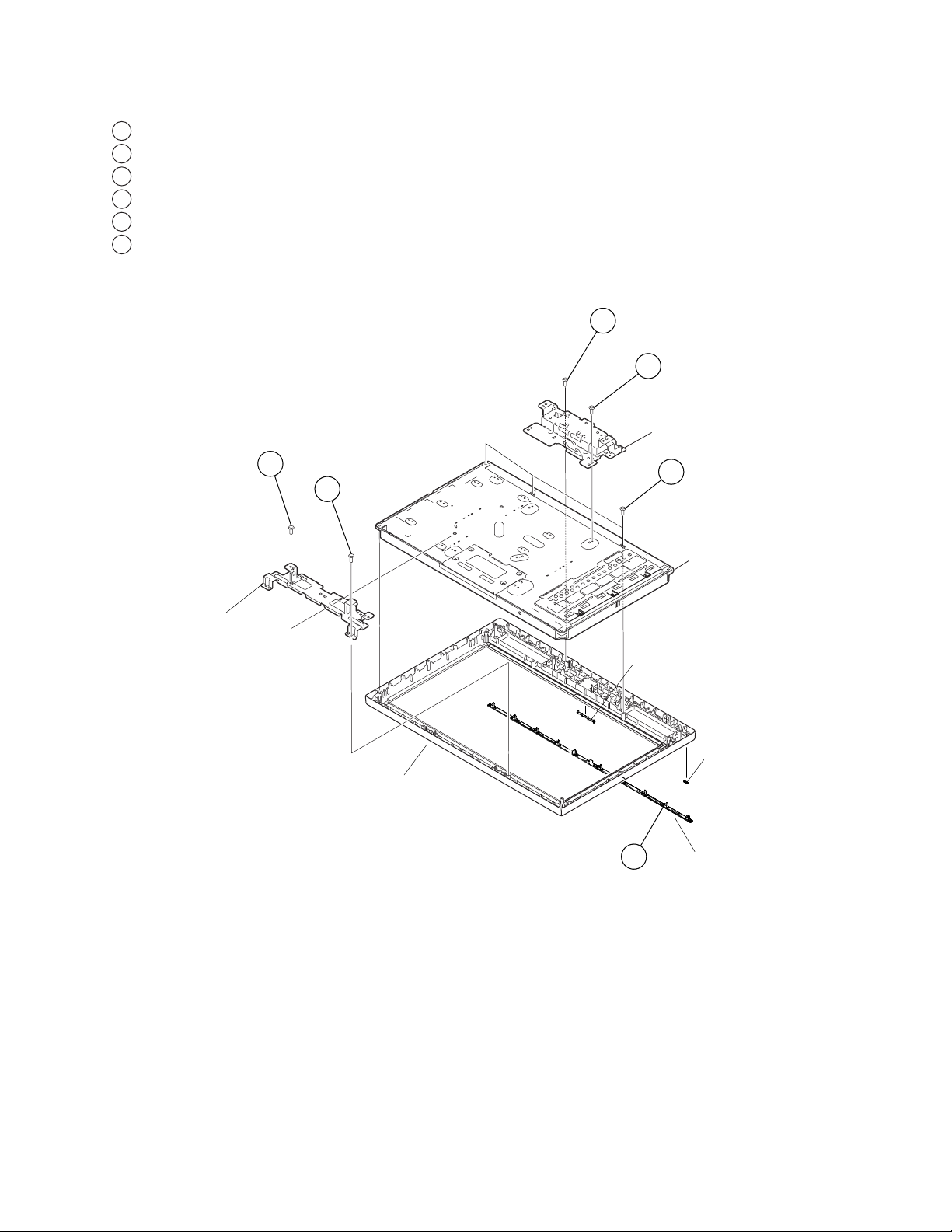
1-13. LCD PANEL, LED AND GUIDE LIGHT REMOVAL (KDL-40SL130 ONLY)
1
Remove 2 screws from Bezel and Top Brackets, +BVTP2 4X16
2
Remove 4 screws from Top Brackets, +PSW M5X8
3
Remove 4 screws from Bottom Brackets, + PSW M5X12
4
Remove 4 screws from Stand Holders, +PSW M5X16
5
Remove 2 screws from LCD Panel, +BVTP2 4X16
6
Remove ornamental panel and slide out LED Guide and Light Guide
3
Stand Holder
4
Bottom Bracket(L)
KDL-32SL130/40SL130
Bezel
Top Bracket
1
2
6
Bottom Bracket(R)
5
LCD Panel
LED Guide
Guide Light
Ornamental Panel
KDL-32SL130/40SL130
19
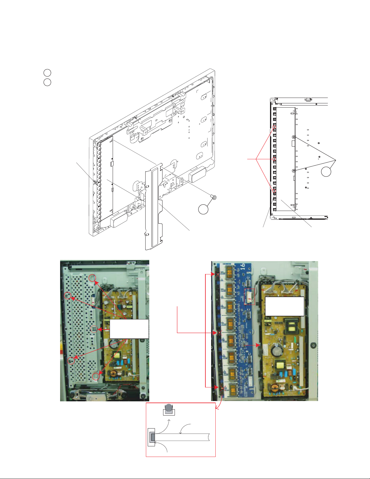
1-14. INVERTER BOARD REMOVAL
CAUTION:
Be sure to identify the inverter cover screws before proceeding. DO NOT remove the screws securing the plastic strip
holding the lamp sockets.
1
Remove screws securing the inverter cover.
2
Remove screws securing the inverter board
Plastic Strip
holding
Lamp Socket
DO NOT
REMOVE
BACKLIGHT
SCREWS
KDL-32SL130/40SL130
2
REMOVE SCREWS
SECURING
SHIELD
Inverter Cover
WARNING
NEVER REMOVE THE
SCREWS SECURING THE
PLASTIC STRIP HOLDING
THE LAMP SOCKETS
DAMAGE TO TH E
BACKLIGHT TUBES WILL
OCCUR!
!
.
1
Plastic Strip
Inverter Board
holding
Lamp Socket
REMOVE
CONNECTOR AND
PULL BOARD TO
THE RIGHT
KDL-32SL130/40SL130
SHIELD REMOVAL
END VIEW
SOCKET
BACKLIGHT
INVERTER BOARD REMOVAL
Only remove the screws securing the inverter
cover which may be metal or plastic. The
remaining plastic strip contains sockets for the
fluorescent backlights and should never be
loosened. The backlights will pop out of the
sockets and/or break the backlight requiring a
LCD panel replacement. The example shown
is a 32” model but applies to all models.
20
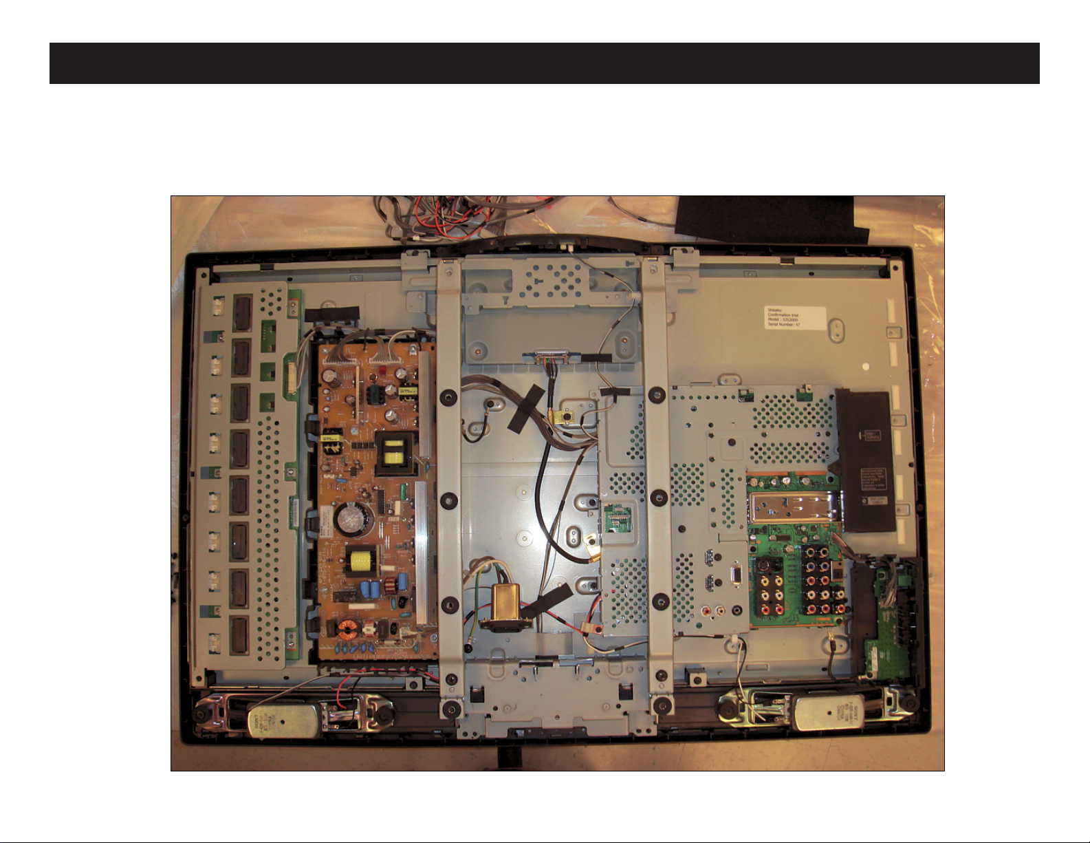
KDL-32SL130 ONLY
OVERALL VIEW
KDL-32SL130/40SL130
WIRE DRESSING
KDL-32SL130/40SL130
21
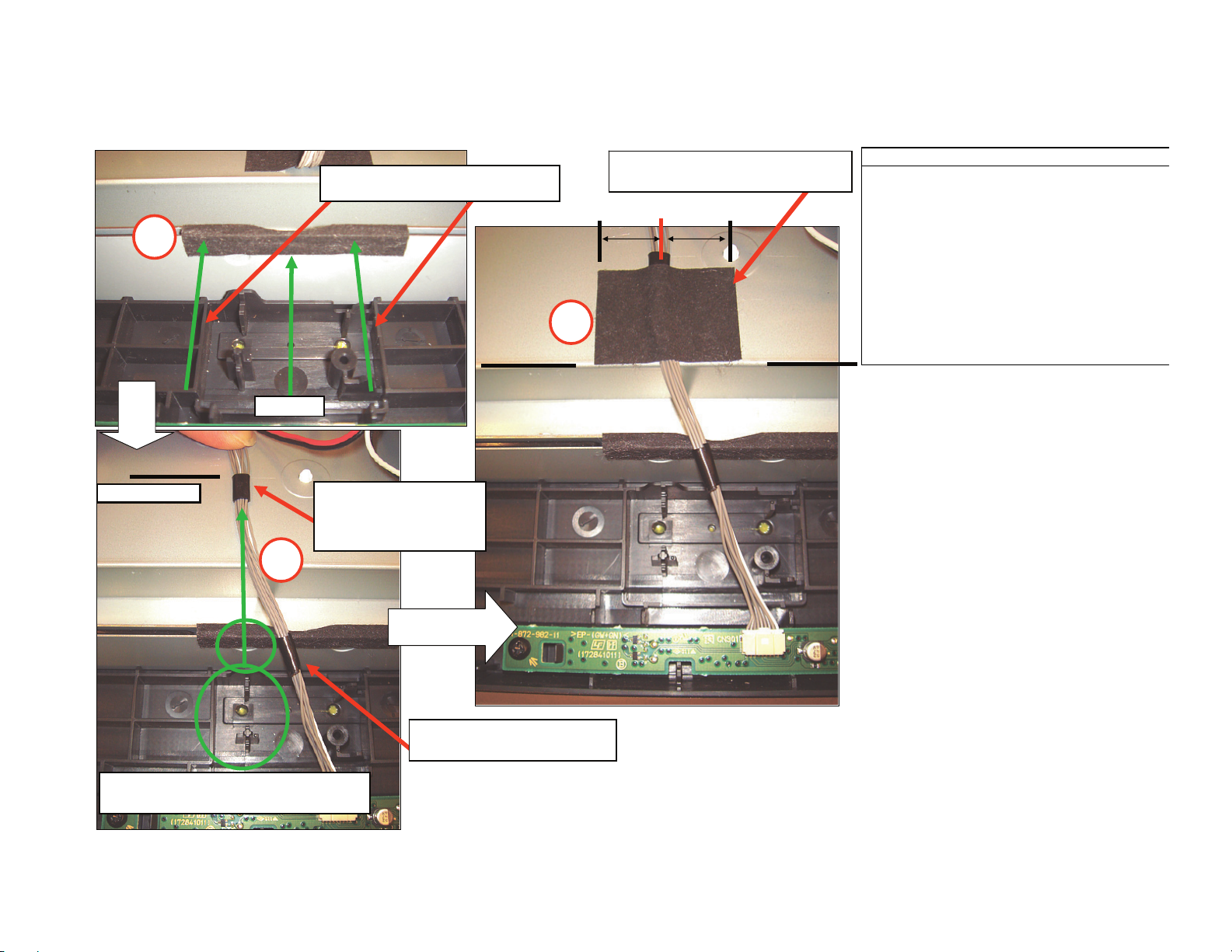
KDL-32SL130 ONLY
H3 BOARD HARNESS
KDL-32SL130/40SL130
3
㪪㪺㫆㫉㪼㩷㪣㫀㫅㪼㩷㪿㪼㫀㪾㪿㫋
㪤㫀㪻㪄㪧㫆㫀㫅㫋
1
Use Ribs on Bezel as Reference to
position Sheet Core C on Panel edge.
Align top of UL tape with
"Score Line" on Panel and
center of "Circle" on Panel
Frame.
2
Center Cushion D over Wires.
Align Cushion D w/edge of panel.
OPERATION PROCESS
1. Apply Sheet Core C to edge of Panel to
cover sharp edge of panel.
2. Align H3 harness as shown in photo. Take
caution not to create tension on the H3
connector! Connector will unlock.
3. Apply Cushion D as shown in 3rd photo.
Use boss and SONY emblem hole
on bezel to align UL tape on harness.
KDL-32SL130/40SL130
Make sure 1st tape is below
himelon tape on panel edge.
22
KDL-32SL130 ONLY
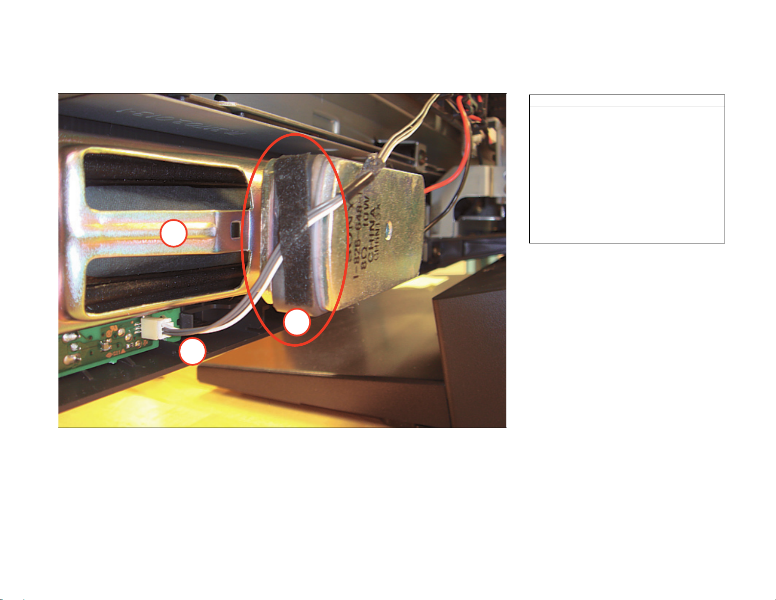
H4 BOARD
KDL-32SL130/40SL130
OPERATION PROCESS
1. Install H4-Bd BEFORE Installing the
speakers/baffles.
2. Apply LCD Tape on SIDE of the magnet
on Rt. Speaker to hold the H4 Cables.
3. MAKE SURE there is slack in the cable between
the H4 Connector and LCD Tape.
Tension on the cable will cause the Connector
to lift or break.
1
KDL-32SL130/40SL130
2
3
×
23

KDL-32SL130 ONLY
H4 BOARD AND RIGHT SPEAKER
1
Dress BOTH H4/Speaker Cables in 3 plastic
clips on G-Bracket.
NOTE: Speaker cables are NOT dressed inside
far left clip on G-Bracket.
2
KDL-32SL130/40SL130
OPERATION PROCESS
Wire Dress Rt. Speaker wires and H4
cables in G-Bracket clips (x3)
NOTE: Rt. Spkr. Wires are NOT dressed
in far LEFT G-Bracket clip!
KDL-32SL130/40SL130
24
KDL-32SL130 ONLY
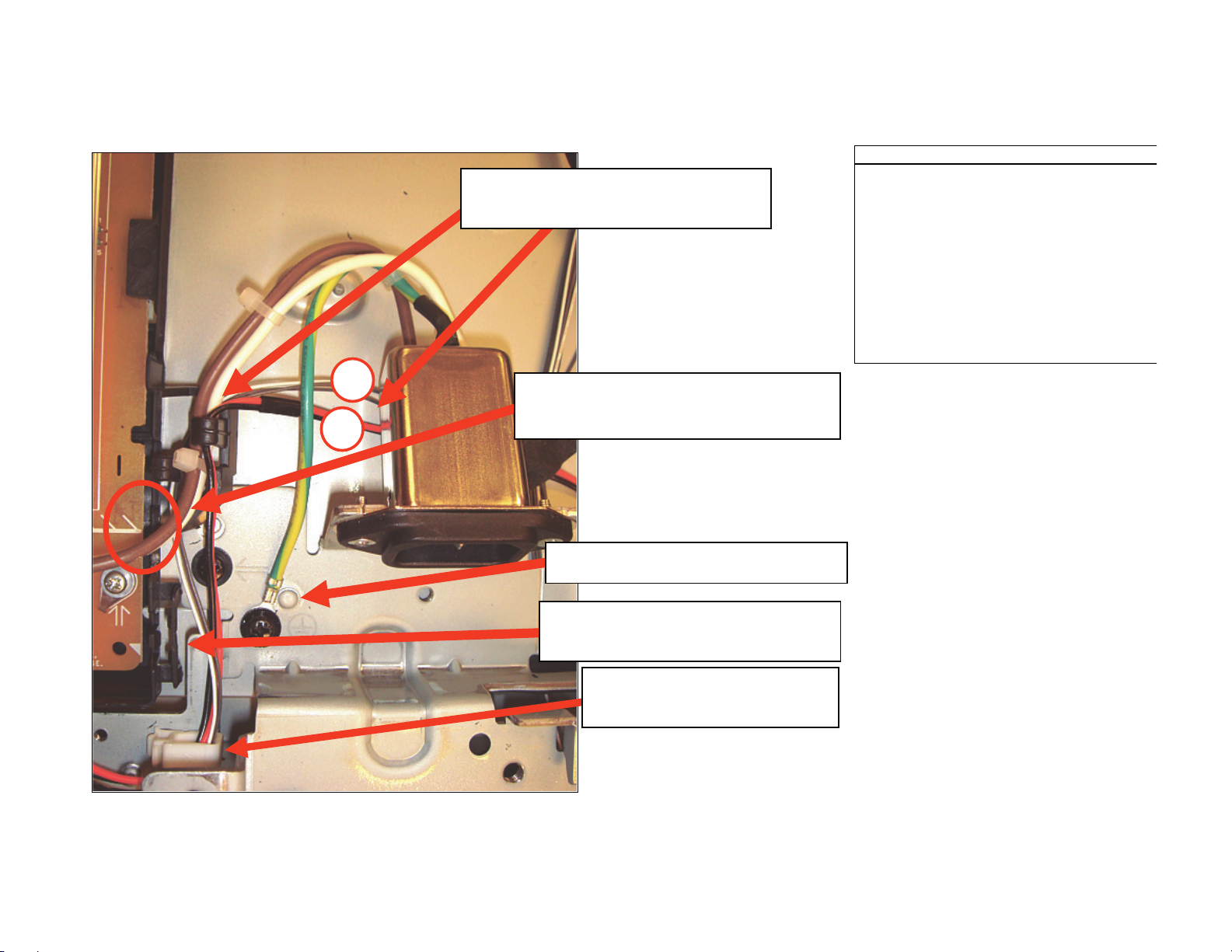
H4 BOARD AND RIGHT SPEAKER (CONTINUED)
NOTE BOTH H4-Bd and Rt. Speaker cables
are dressed UNDER AC Inlet and in G-Brkt
clamp with AC Inlet Wires.
KDL-32SL130/40SL130
OPERATION PROCESS
1. Wire Dress Right Speaker wires and H4
cables in side clamp (white) and G3-Bd
bracket clip (black).
NOTE: H4-Bd/Rt. Speaker cables are dressed
UNDER AC Inlet.
2. Dress AC Inlet cables as shown.
Make sure Green/Yellow Earth Gnd. Is screwed
into lower LCD Bracket (w/4x8mm screw)
2
1
CAUTION: DO NOT Push hard on AC
inlet wires after routing inside G1 bracket!!
Wire Insulation can be CUT by plastic edges!
NOTE Angle of Earth Gnd. Wire.
(Ring terminal touches "dimple" on plate)
NOTE Wires NOT dressed in small clip on
G1-Bracket. (Too difficult to dress with
gloves over hands)
NOTE: H4-Bd/Right Speaker cables
DRESSED INSIDE in plastic clip.
CLIP NOT ELIMNATED!!
KDL-32SL130/40SL130
25
KDL-32SL130 ONLY
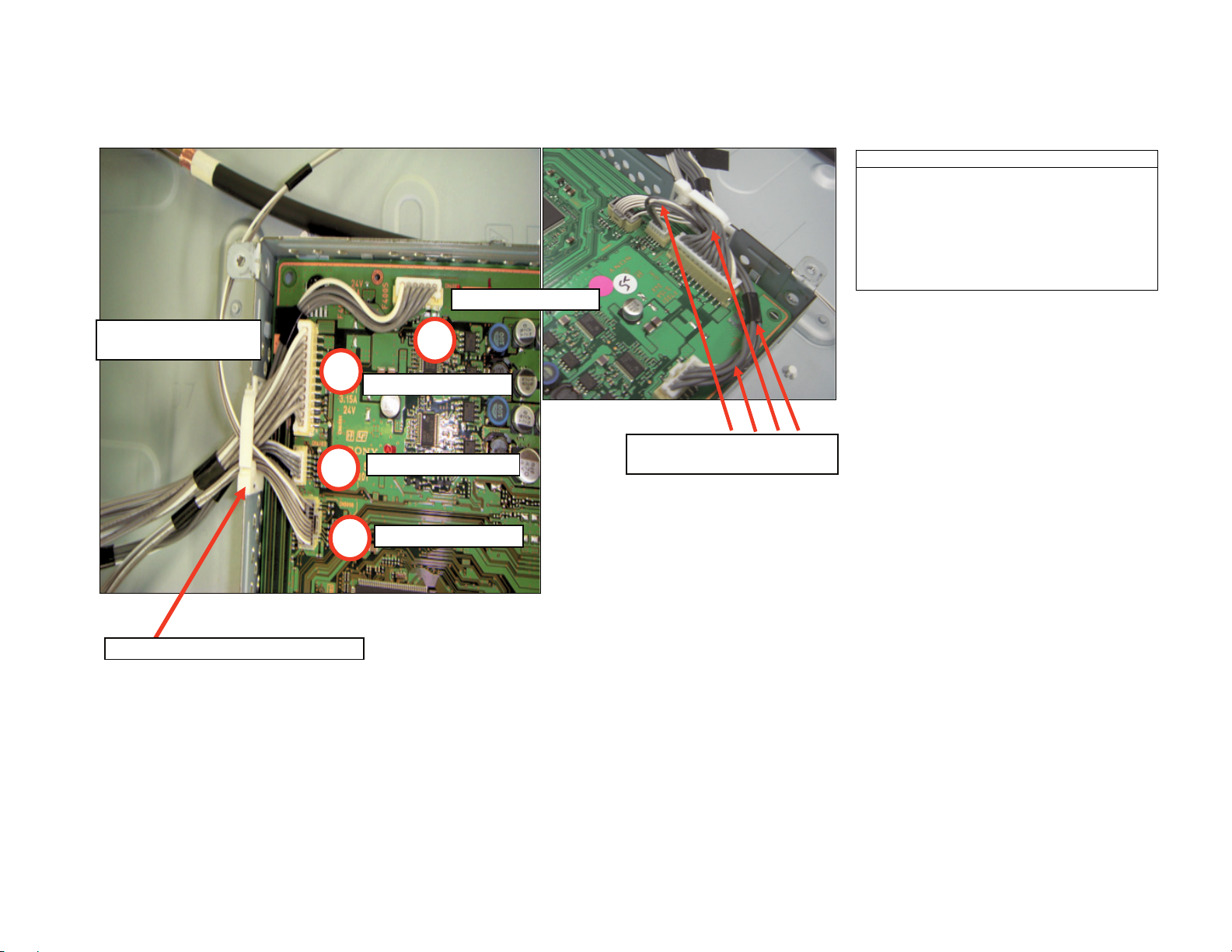
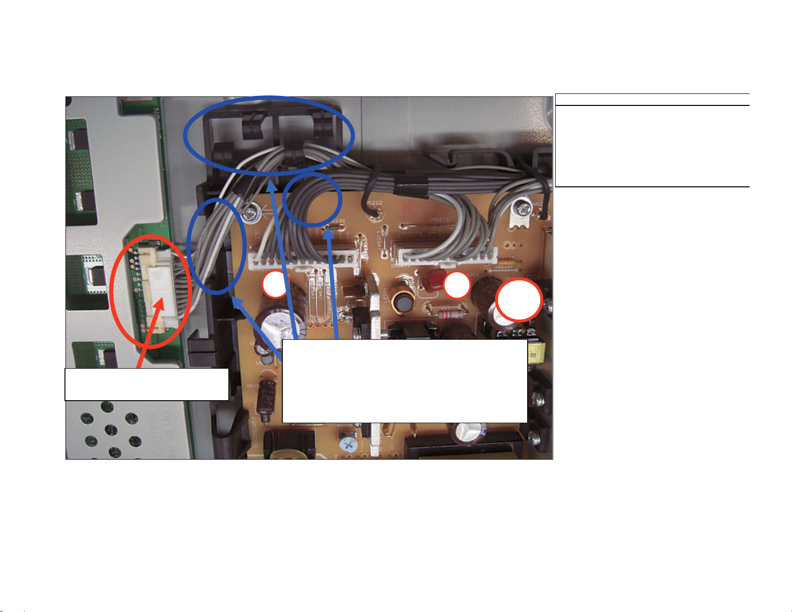
CORE BLOCK HARNESS
KDL-32SL130/40SL130
OPERATION PROCESS
Route/Dress Harnesses connected to
Core Block as Shown
NOTE Order & Direction of Cables in
plastic Clip on Shield Case.
DRESS CABLES 1st
DRESS CABLES LAST
ON TOP ALL CABLES.
NOTE order and direction of cables!
2
DRESS CABLES 3rd
DRESS CABLES 2nd
1
DRESS CABLES 4th
3
1
Keep Cables BELOW level
of Shield Case (Pinch Points)
KDL-32SL130/40SL130
26
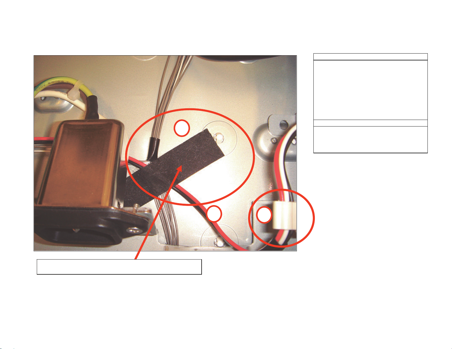
KDL-32SL130 ONLY
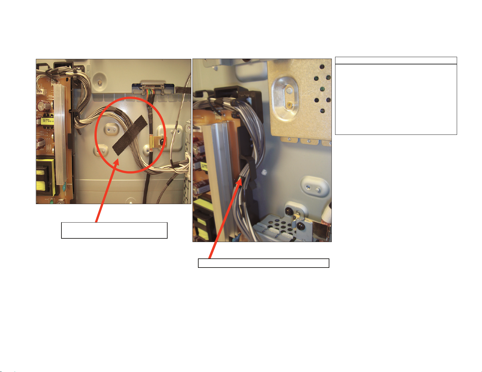
CORE BLOCK HARNESS (CONTINUED)
1
1
KDL-32SL130/40SL130
OPERATION PROCESS
Route/Dress Core-Block cables as shown
Put Attention on DIRECTION of cables
in G-Bracket.
Put Attention on the position of the Sheet Core C
and routing of the Cables between Core Block
and G1-Bracket.
NOTE Routing of cables and position
of Sheet Core C.
KDL-32SL130/40SL130
NOTE direction of wires dressed in G-Bracket.
27
KDL-32SL130 ONLY
G1H BOARD
KDL-32SL130/40SL130
OPERATION PROCESS
Install/Wire Dress Harnesses as shown.
CAUTION: Make sure INVERTER CONN.
is Fully LOCKED!!
CAUTION: Make Sure Inverter
Connector is Fully LOCKED!
2
1
NOTE: NEW G-Bracket Change!
Inverter wire is NOT dressed in 1st clip.
Inverter wires are dressed in cut-out on
side of the G-Bracket and the 2nd clip on right.
13P harness is NOT dressed in any of the
clips above PWB!
G1H-
Bd
KDL-32SL130/40SL130
28
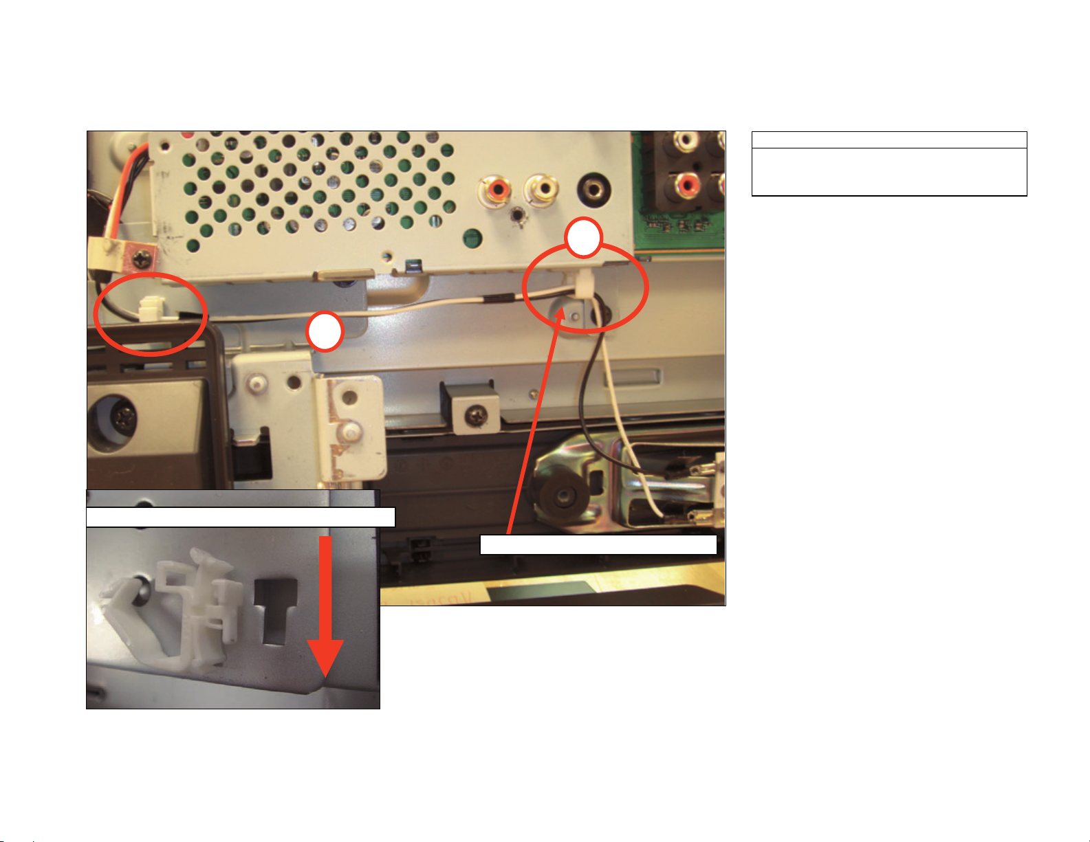
KDL-32SL130 ONLY
SPEAKER HARNESS
KDL-32SL130/40SL130
OPERATION PROCESS
1. Wire Dress Speaker Cables as shown.
2. BOTH R/L cables are dressed in FGC-3
conductive clip.
3. Apply LCD TAPE to BOTH H4-Bd AND Right
Speaker Wires.
TORQUE SPECIFICATION
3
TORQUE: 6kg.cm (+-1.0kg.cm)
Apply Sheet Core C to BOTH H4/H3 AND Right Speaker Wires.
Align edge of tape with White Plastic Peg On Panel.
KDL-32SL130/40SL130
1
2
29
KDL-32SL130 ONLY
LEFT SPEAKER HARNESS
KDL-32SL130/40SL130
OPERATION PROCESS
Dress LEFT speaker harness as shown
2
1
PUSH SIDE CLAMP THIS DIRECTION TO LOCK!!
KDL-32SL130/40SL130
Side Clamp Installed by SBC PLANT!
30
 Loading...