

Page 1

HISTORY
Model Name :
SERVICE MANUAL
Click on Page Number to display detail of changes.
KDL-32/37/40S5600
Date Part Number Description of Revisions
Version
1.09-883-454-01 2009.05
Original Manual.
2.09-883-454-02 2009.06
Add 32” Inverter Board to the Exploded Views.
(P38)
3.09-883-454-03 2009.07
Commonize ‘B’ Board.
(P37 / P42)
2010.08 9-883-454-04 How to Delete “Error History” (P9) 4.0
Page 2
- 1 -
SERVICE MANUAL
EX2N-Peppermint
CHASSIS
MODEL DEST
RM-ED017
KDL-32S5600 OIRT / UK / WE
KDL-37S5600 OIRT / UK / WE
KDL-40S5600 OIRT / UK / WE
Page 3

- 2 -
TABLE OF CONTENTS
Section Title Page Section Title Page
1. GENERAL
Caution ................................................................ 3
Specifications ...................................................... 6
Connectors ........................................................... 8
Self Diagnosis ..................................................... 9
2. DISASSEMBLY
2-1. Rear Cover Removal (Step 1) ............................... 10
2-2. Rear Cover Removal (Step 2) ............................... 10
2-3. Stand Assy Removal .............................................. 10
2-4. Under Cover Removal ........................................... 10
2-5. Switch Unit Removal ............................................. 11
2-6. Loudspeaker Removal ........................................... 11
2-7. Side Bracket Removal ........................................... 11
2-8. B Board Removal ................................................... 11
2-9. H1 Board Removal ................................................ 12
2-10. G2 Board Removal (32 inches) ........................... 12
2-11. G4 Board Removal (37 inches) ........................... 12
2-12. IP1F Board Removal (40 inches) ......................... 12
3. SERVICE MENUS
3-1. How to enter the Service Mode .......................... 13
3-2. Service Menu Structure ...................................... 13
3-2-1. Service General Menu .................................. 13
3-2-2. White Balance Adjustment ........................... 13
3-2-3. OSD Service Menu ...................................... 14
3-2-4. Country Selection ......................................... 14
3-2-5. Factory Reset ................................................ 14
3-3. TT Mode ............................................................. 15
4. DIAGRAMS
4-1. Block Diagram ................................................... 16
4-2. Circuit Board Location ....................................... 17
4-3. Schematic Diagrams and Printed Wiring
Boards ................................................................. 17
B Board Schematic Diagram ........................... 18
H1 Board Schematic Diagram ........................... 30
IP1F Board Schematic Diagram (40 inches) ..... 31
B Printed Wiring Board ....................................... 33
H1 Printed Wiring Board ..................................... 34
IP1F Printed Wiring Board (40 inches) ............... 35
5. EXPLODED VIEWS
5-1. Chassis ................................................................ 37
5-2. Bezel Assy & Stand Assy ................................... 39
5-3. Rear Cover & Power Supply Cords .................... 40
6. PARTS LIST
............................................................... . 41
SAFETY-RELATED COMPONENT WARNING !!
COMPONENTS IDENTIFIED BY SHADING AND MARKED £ ON
THE EXPLODED VIEWS AND IN THE PARTS LIST ARE CRITICAL
FOR SAFE OPERATION. REPLACE THESE COMPONENTS WITH
SONY PARTS WHOSE PART NUMBERS APPEAR AS SHOWN IN
THIS MANUAL OR IN SUPPLEMENTS PUBLISHED BY SONY.
WARNING !!
AN ISOLATION TRANSFORMER SHOULD BE USED DURING ANY
SERVICE WORK TO AVOID POSSIBLE SHOCK HAZARD DUE TO
LIVE CHASSIS, THE CHASSIS OF THIS RECEIVER IS DIRECTLY
CONNECTED TO THE POWER LINE.
Page 4
- 3 -
SECTION 1 GENERAL
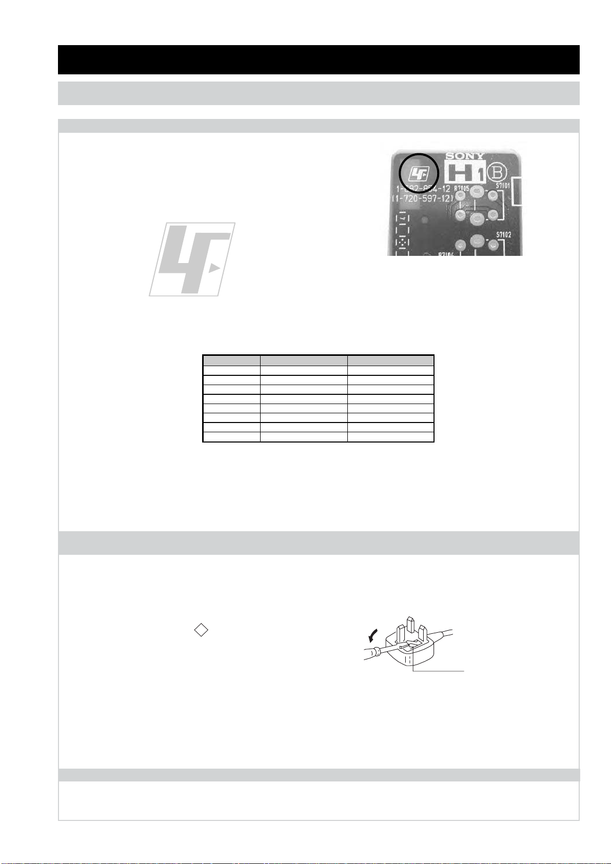
The circuit boards used in these models have been processed using
Lead Free Solder. The boards are identified by the LF logo located
close to the board designation e.g. H1 etc [ see example ]. The
servicing of these boards requires special precautions to be taken as
outlined below.
Lead Free Soldered Boards
example
Lead Free Solder material must be used to comply with environmental requirements of new solder joints. Lead Free Solder is available
under the following part numbers :
Due to the higher melting point of Lead Free Solder the soldering iron tip temperature needs to be set to 370 degrees centigrade. This
requires soldering equipment capable of accurate temperature control coupled with a good heat recovery characteristics.
For more information on the use of Lead Free Solder, please refer to
http://www.sony-training.com
Partnumber Diameter Remarks
7-640-005-19 0.3mm 0.25Kg
7-640-005-20 0.4mm 0.50Kg
7-640-005-21 0.5mm 0.50Kg
7-640-005-22 0.6mm 0.25Kg
7-640-005-23 0.8mm 1.00Kg
7-640-005-24 1.0mm 1.00Kg
7-640-005-25 1.2mm 1.00Kg
7-640-005-26 1.6mm 1.00Kg
CAUTION
SECTION 1 GENERAL
How to replace the fuse.
Open the fuse compartment with
a screwdriver blade and replace
the fuse.
FUSE
WARNING (UK Models only)
The flexible mains lead is supplied connected to a
B.S. 1363
fused
plug having a fuse of the correct rating for the set. Should the fuse
need to be replaced, use a fuse of the same rating approved by ASTA
to
BS 1362
, ie one that carries the
ASA
T
mark.
mark.
IF THE PLUG SUPPLIED WITH THIS APPLIANCE IS NOT SUITABLE
FOR THE OUTLET SOCKETS IN YOUR HOME, IT SHOULD BE CUT
OFF AND AN APPROPRIATE PLUG FITTED. THE PLUG SEVERED
FROM THE MAINS LEAD MUST BE DESTROYED AS A PLUG WITH
BARED WIRES IS DANGEROUS IF ENGAGED IN A LIVE SOCKET.
When an alternative type of plug is used, it should be fitted with the
correct rating fuse, otherwise the circuit should be protected by the
same rating fuse at the distribution board.
UK PLUG W ARNING
LCD PANEL CAUTION
Whilst working on this product, it is not recommended to lay the TV set face down when powered up, as this can result in panel problems.
If it is necessary to power up the TV set when face down, the time should be minimised as much as possible.
Page 5
- 4 -
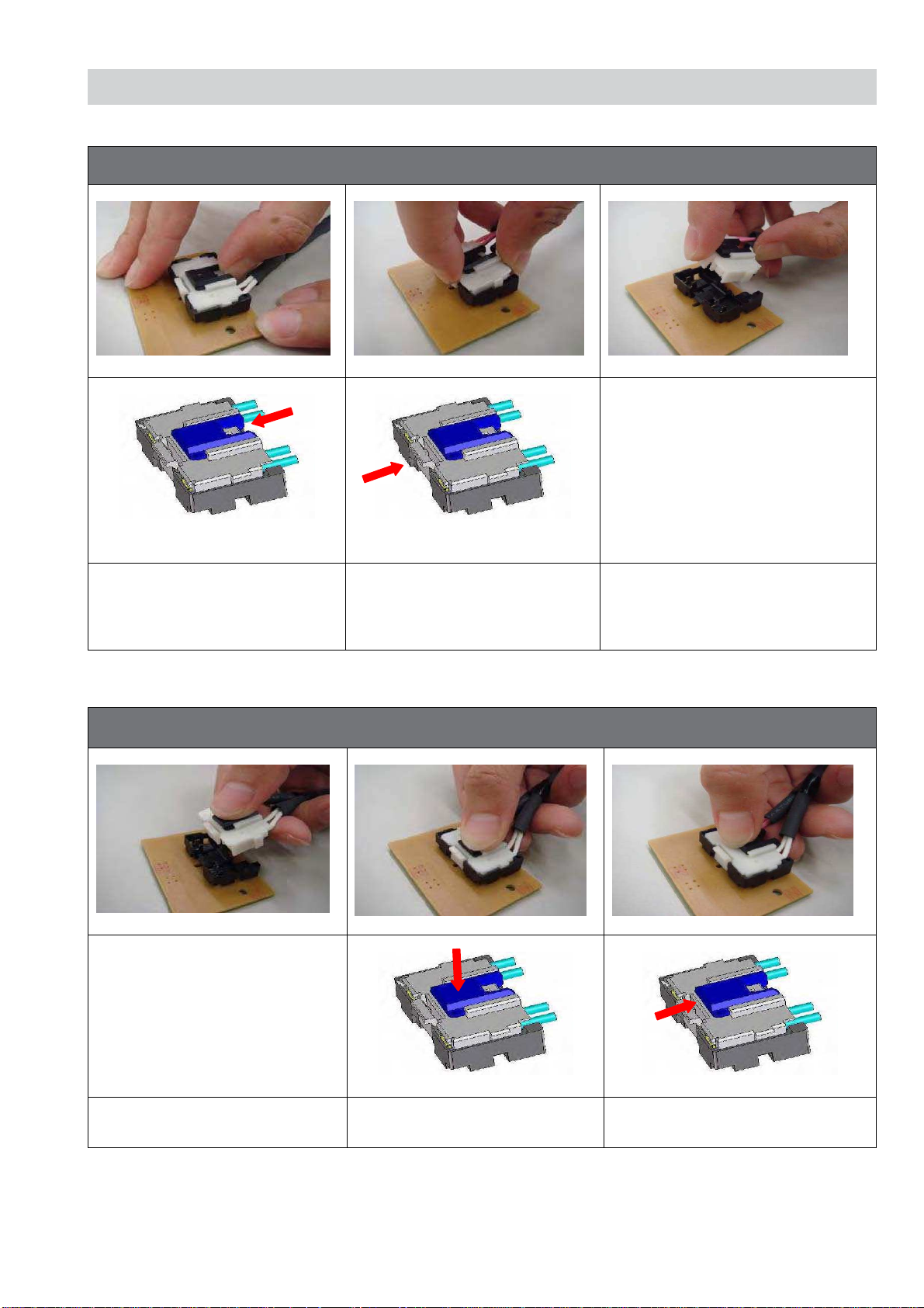
CAUTION
1. MDF-61 Connector (Removal)
Slide the slider to release slider
lock.
Press the centre lock tab to
release the lock and pull the
connector up
Remove connector
2. MDF-61 Connector (Refiitting)
Hold the centre of connector Press centre of connector to insert Slide the slider to lock connector
Page 6
- 5 -
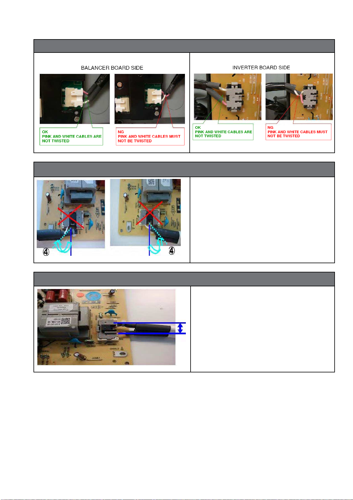
3. The harness must not be crossed or twisted
4. Wire Dressing at connector
The harness must not bend more
than 45 degrees from the direction of
the connector base to avoid crossing
or twisting.
5. Wire distance at connector
The distance between each wire must
be wider than 4mm to ensure isolation from lamp voltage.
Page 7
- 6 -
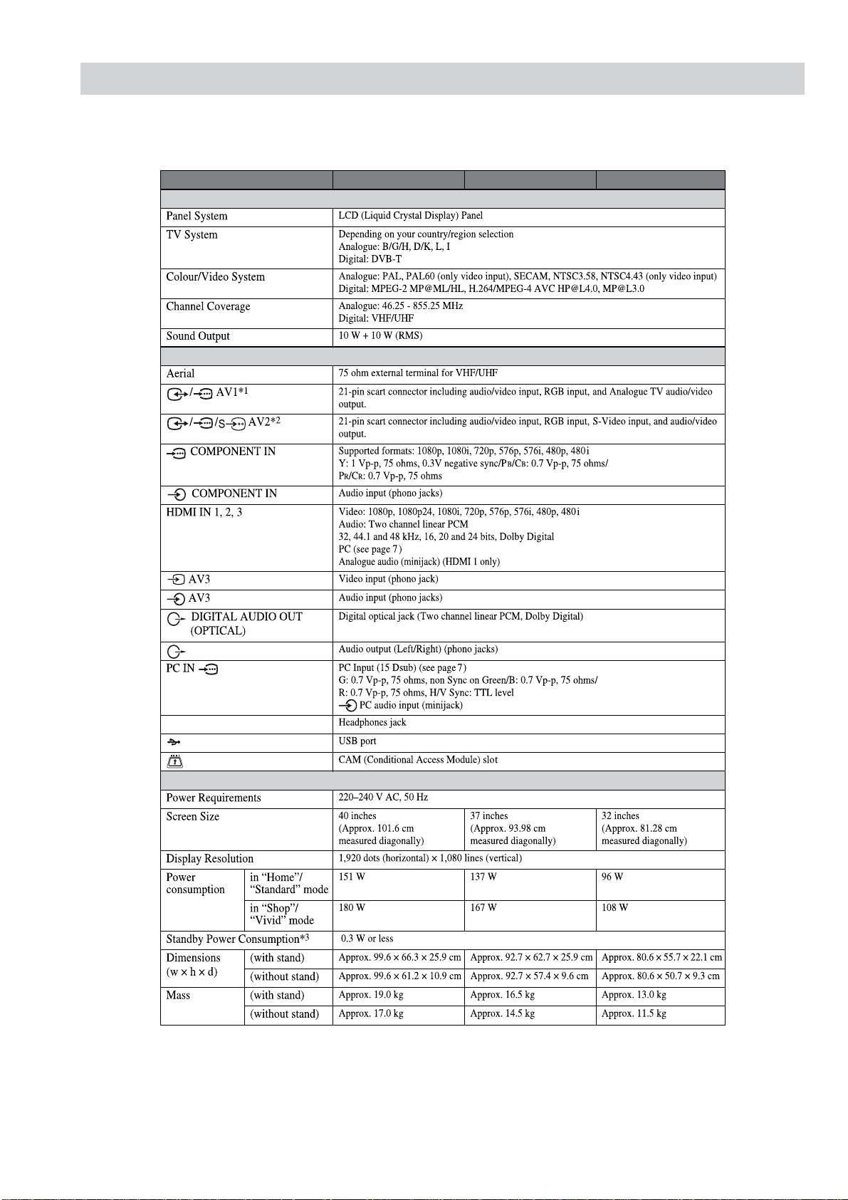
SPECIFICATIONS
Model name KDL-40S56/P56/P36xx KDL-37S56/P56xx KDL-32S56/P56/P36xx
System
Input/Output jacks
i
Power and others
Page 8
- 7 -
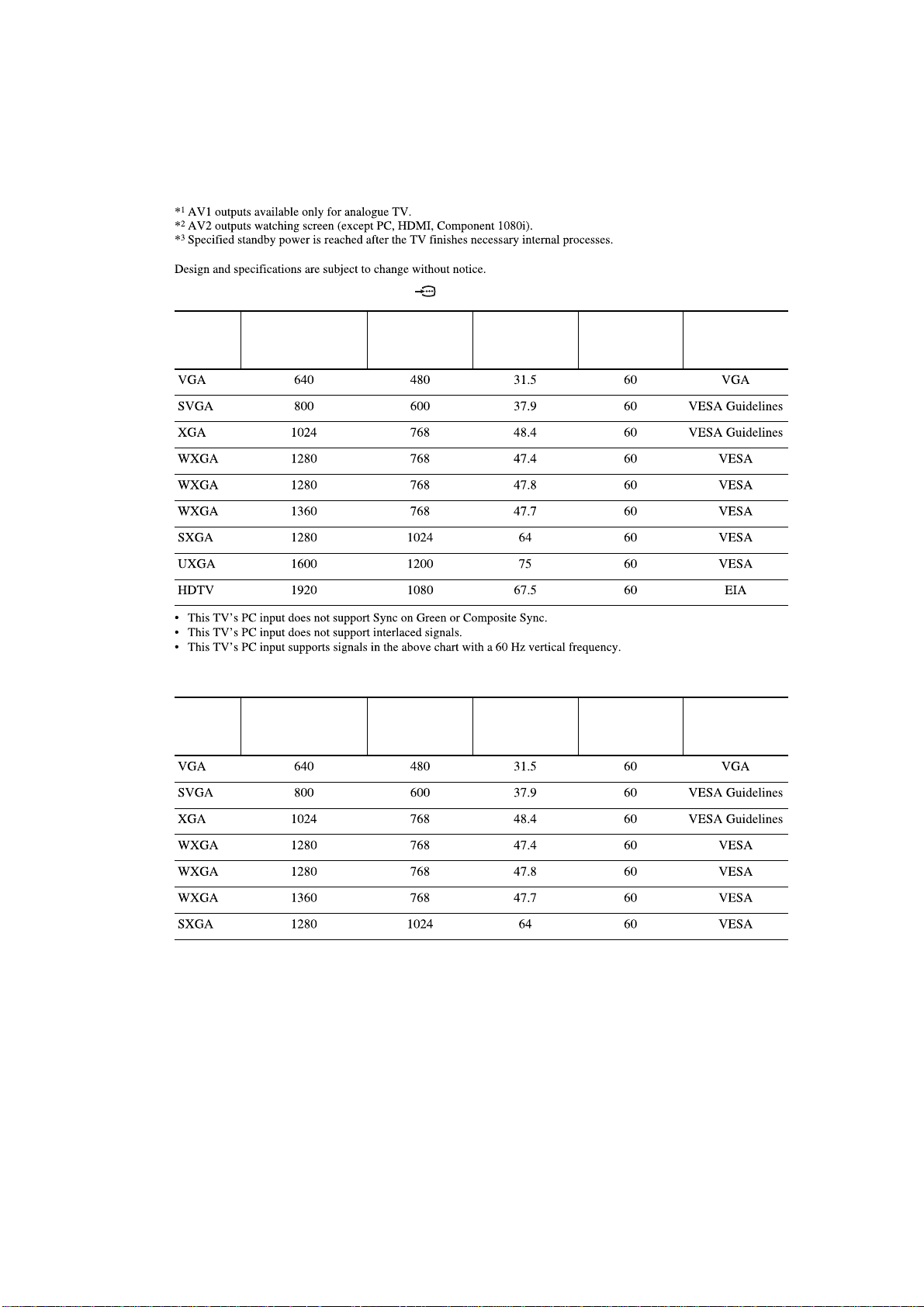
PC Input Signal Reference Chart for PC IN
PC Input Signal Reference Chart for HDMI IN 1, 2 and 3
Signals Horizontal (Pixel)Vertical (Line)
Horizontal
frequency
(kHz)
Vertical
frequency (Hz)
Standard
Signals Horizontal (Pixel)Vertical (Line)
Horizontal
frequency
(kHz)
Vertical
frequency (Hz)
Standard
Page 9
- 8 -
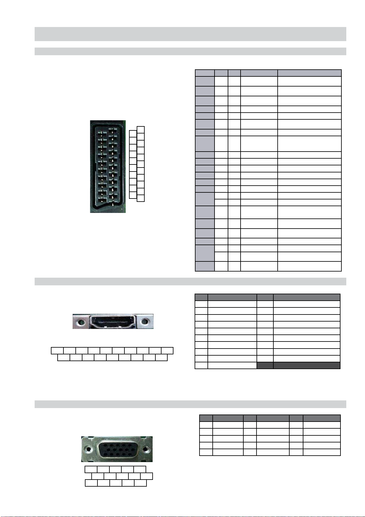
CONNECTORS
21 Pin Connector (SCART)
HDMI Connector
15 Pin D Sub Connector (PC)
Pin No AV-1 AV- 2 Signal Signal Level
1 • • Audio Output B
(Right)
Standard Level: 0.5V rms
Impedance: less than 1K
*
2 • • Audio Input B
(Right)
Standard Level: 0.5V rms
Impedance: more than 10K
*
3 • • Audio Output A
(Left)
Standard Level: 0.5V rms
Impedance: less than 1K
*
4 • • Ground (Audio)
5 • • Ground (Blue)
6 • • Audio Input A (Left) Standard Level: 0.5V rms
Impedance: more than 10K
*
7 • • Blue Input 0.7V +/- 3dB, 75
, positive
8 • • Function Select
(AV control)
High State (9.5~12V): AV mode
Low State (0~2V): TV mode
Impedance: more than 10K
*
Capacitance: less than 2nF
9 • • Ground (Green)
10 - • AV Link
11 • • Green Input 0.7V +/- 3dB, 75
positive
12 - • Open
13 • • Ground (Red)
14 • • Ground (Blanking)
15
• • Red Input 0.7V +/- 3dB, 75
positive
• • S signal Chroma Input 0.3V +/-3dB, 75
positive
16 • • Blanking Input
(Y Signal)
High State (1~3V)
Low State (0~0.4V)
Impedance: 75
17 • • Ground
(Video Output)
18 • • Ground
(Video Input)
19 • • Video Output 1V +/-3dB, positive sync 0.3V (-3+10dB)
20
• • Video Input 1V +/-3dB, positive sync 0.3V (-3+10dB)
• • Video Input Y
(S Signal)
1V +/-3dB, positive sync 0.3V (-3+10dB)
21
• • Common Ground
(Shield)
1
3
5
7
9
11
13
15
17
19
21
2
4
6
8
10
12
14
16
18
20
19 17 15 13 11 9 7 5 3 1
18 16 14 12 10 8 6 4 2
5 4 3 2 1
10 9 8 7 6
15 14 13 12 11
Pin No Signal Assignment Pin No Signal Assignment Pin No Signal Assignment
1 Red Output 6 Red Return 11 Monitor IDO in display
2 Green Output 7 Green Return (Ground) 12 DCC Serial Data
3 Blue Output 8 Blue Return (Ground) 13 Horizontal Sync
4 Unused 9 +5V DC 14 Vertical Sync
5 Ground 10 Sync Return (Ground) 15 DCC Serial Clock
Pin No Signal Assignment Pin No Signal Assignment
1 TMDS Data2+ 11 TDMS Clock Shield
2 TMDS Data2 Shield 12 TMDS Clock-
3 TMDS Data2- 13 CEC
4 TMDS Data1+ 14 Reserved (N.C. on device)
5 TMDS Data1 Shield 15 SCL
6 TMDS Data1- 16 SDA
7 TMDS Data0+ 17 DDC/CEC Ground
8 TMDS Data0 Shield 18 +5V power
9 TMDS Data0- 19 Hot Plug Detect
10 TMDS Clock+
Page 10
- 9 -
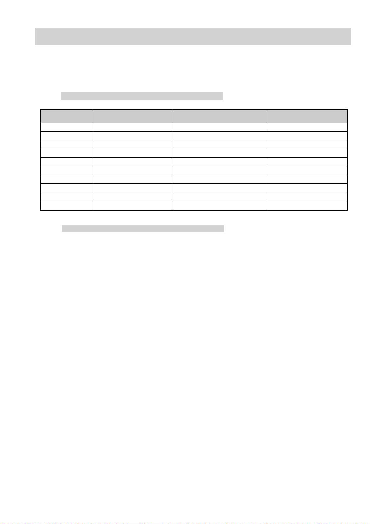
EX2N SELF DIAGNOSTIC SOFTWARE
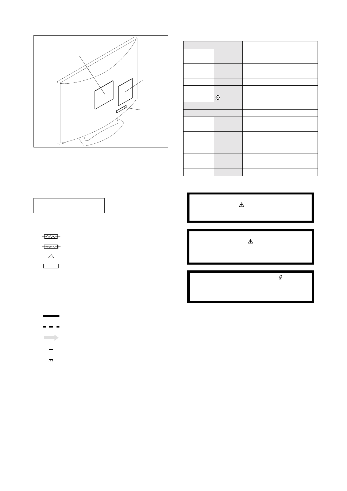
The identification of errors within the EX2N chassis is triggered in one of two ways :- 1: Busy or 2: Device failure to respond to IIC. In the
event of one of these situations arising the software will first try to release the bus if busy (Failure to do so will report with a continuous flashing LED) and then communicate with each device in turn to establish if a device is faulty. If a device is found to be faulty the relevant device
number will be displayed through the LED (Series of flashes which must be counted).
LED Error Codes and Descriptions
Number of LED
Flashes
Error Description Checked Action
02 Balancer error. In normal and factory mode. Goes into standby.
03 Power supply protection error. In normal and factory mode. Goes into standby.
04 Inverter error. In nor mal and factory mode. Goes into standby.
05 NVM error. In initialisation state. Adds error to error menu.
06 IIC error. In normal and factory mode. Adds error to error menu.
08 Audio error. In normal and factory mode. Adds error to error menu.
09 Tuner error. In initialisation state. Adds error to error menu.
18 COFDM error. In digital mode and initialisation state. Adds error to error menu.
19 USB error. In normal and factory mode. Adds error to error menu.
20 CI error. In normal and factory mode. Adds error to error menu.
Delete “Error History” in Service Menu
1. Confirm latest software version is fitted.
2. Enter Factory Mode : TT19
3. Set Shipping Condition : TT08
4. Confirm Error History deleted
Ver 4.0
Page 11
- 10 -
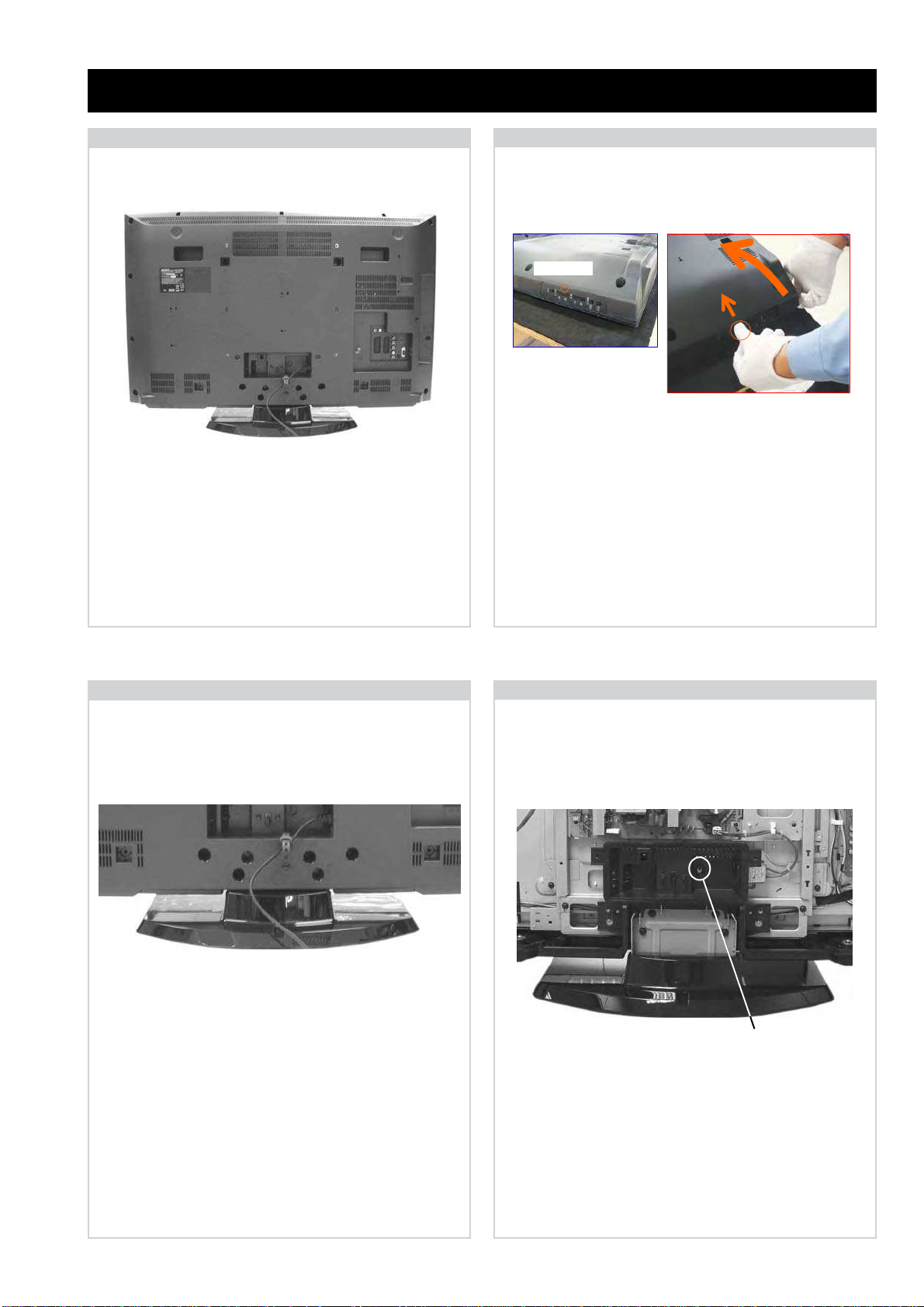
2-1. Rear Cover Removal (Step 1)
SECTION 2 DISASSEMBLY
2-2. Rear Cover Removal (Step 2)
2-3. Stand Assy Removal
2-4. Under Cover Removal
To remove the ‘Under Cover’ first remove the Rear Cover
(See Sec 2-2-1 & 2-2-2) and then remove the Stand Assy
(See Sec 2-2-3). Then remove the 1 screw circled and gently
pull the ‘Under Cover’ away from the back of the TV set.
=>
1
=>
=>
1
=>
1
=>
1
=>
1
=>
1
=>
1
=>
Remove the rear cover fixing screws indicated and refer to
Sec 2-2-2.
Screw Part number(s) and Description(s)
1) 2-580-640-01 SCREW, +BVTP2 4X16 (32/37” = 12pcs, 40” = 11pcs)
2) 7-685-648-79 SCREW, +BVTP 3X12 (32/37/40” = 2pcs)
3) 2-580-602-01 SCREW, +PSW M4X12 (32” = 2pcs, 37/40” = 4pcs)
Remove the 4 stand fixing screws indicated and lift the TV
set up and away from the ‘Stand Assy’.
Screw Part number(s) and Description(s)
2-580-608-01 SCREW, +PSW M5X16
1
1
1
=>
=>
=>
=>
=>
=>
2
1
=>
=>
3
=>
3
=>
1
=>
3
=>
3
=>
2
Screw
Screw Part number(s) and Description(s)
2-580-602-01 SCREW, +PSW M4X12
To remove the ‘Rear Cover’ lift the ‘Rear Cover’ up slightly
from the bottom and then gently push the ‘Switch Unit’ in
by the side controls whilst lifting the ‘Rear Cover’ up fully
from the bottom.
Push point.
Page 12
- 11 -
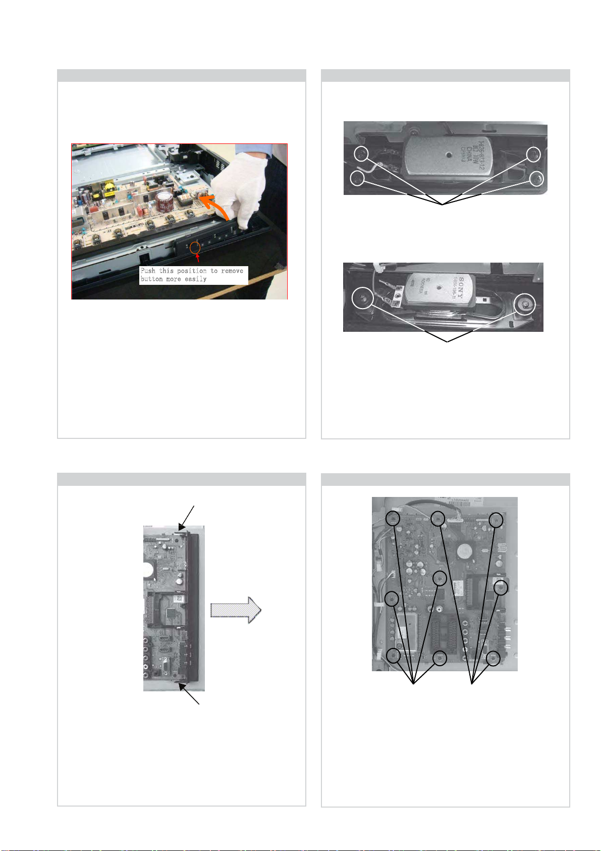
2-8. B Board Removal
To remove the ‘B’ board disconnect all the connectors and
then remove the 9 screws circled and ease the board gently
away from the back of the TV set.
Screws Screws
Screw Part number(s) and Description(s)
2-580-629-01 SCREW, +BVST 3X8
2-6. Loudspeaker Removal
To remove the ‘Loudspeaker’ first disconnect the speaker
cables and then remove the screws circled (32/37” = 4 pcs,
40” = 2 pcs).
Screw Part number(s) and Description(s)
2-580-639-01 SCREW, +BVTP2 4X12 (37 inches)
2-580-654-01 SCREW, +PWTP2 4X16 (40 inches)
Screws
2-7. Side Jack Bracket Removal
Release the 2 clips indicated and gently pull the bracket away
from the ‘B’ board in the direction of the arrow.
Clip
Clip
32 & 37 inches
Screws
40 inches
2-5. Switch Unit Removal
2WUJVJKURQUKVKQPVQTGOQXG
DWVVQPOQTGGCUKN[
To remove the ‘Switch Unit’ lift the bottom of the bracket
towards the TV set. Push the top of the bracket in the shaded
area in the photograph. The bracket will then release from its
boss and can be removed from the TV set.
Page 13
- 12 -
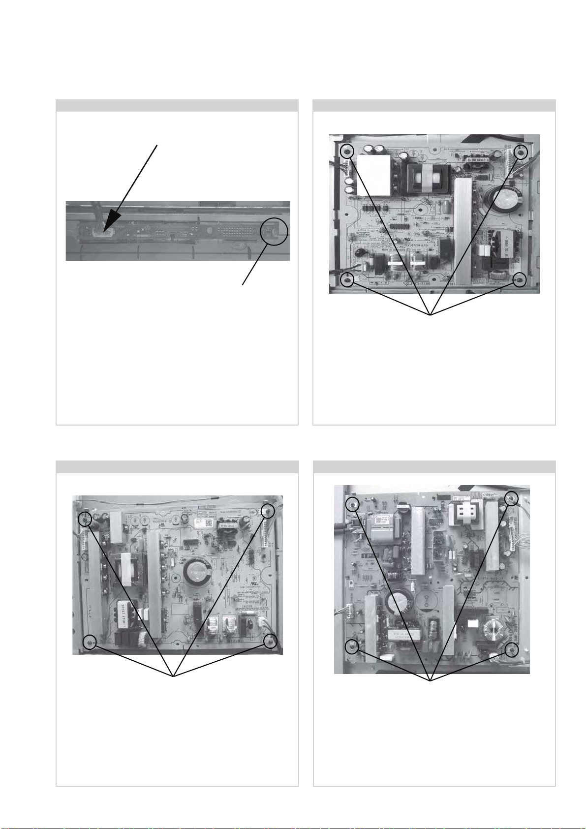
2-10. G2 Board Removal (32 inches)
To remove the ‘G2’ board disconnect all the connectors
and then remove the 4 screws circled and ease the board
gently away from the back of the TV set.
Screw Part number(s) and Description(s)
2-580-629-01 SCREW, +BVST 3X8
Screws
2-12. IP1F Board Removal (40 inches)
Screws
Screw Part number(s) and Description(s)
2-580-629-01 SCREW, +BVST 3X8
To remove the ‘IP1F’ board disconnect all the connectors and
then remove the 4 screws circled and ease the board gently
away from the back of the TV set.
Note:
Refer to page 4 - Hirose MDF61 connector.
2-11. G4 Board Removal (37 inches)
To remove the ‘G4’ board disconnect all the connectors
and then remove the 4 screws circled and ease the board
gently away from the back of the TV set.
Screw Part number(s) and Description(s)
2-580-629-01 SCREW, +BVST 3X8
Screws
2-9. H1 Board Removal
Clip
To remove the ‘H1’ board first remove the ‘Rear Cover’
(See Sec 2-2-1 & 2-2-2) and then remove the ‘Loudspeaker’
(See Sec 2-2-6). The ‘H1’ board can then be removed by
disconnecting the connector indicated and releasing the clip
circled.
Connector
Page 14
- 13 -
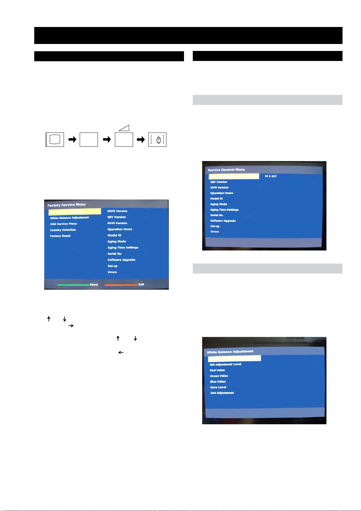
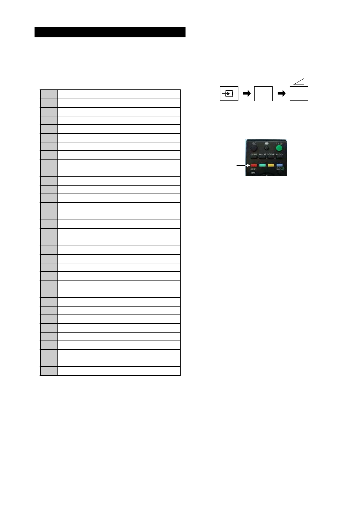
3-1. How to enter the Service Mode
Service adjustments to this model can be performed using the
supplied Remote Commander RM-ED017.
SECTION 3 SERVICE MENUS
3. The following menu appears on the screen (See Pic.1).
4. Move to the corresponding adjustment item using the
‘ ’ or ‘ ’ arrow buttons on the Remote Commander.
5. Press the ‘ ’ arrow button to enter into the required menu
item.
6. Adjust the data value using the ‘ ’ or ‘ ’ arrow buttons on
on the Remote Commander.
7. To go back at any time press the ‘ ’ button on the Remote
Commander.
8.
Ensure you return to the top level menu, shown above in
Pic 1, and press the Green button on the Remote
Commander to Store all the adjustments.
9. Press the Red button or ‘Menu’ button on the Remote
Commander to quit the Service Mode when all adjustments
have been completed.
1. Turn on the power to the TV set.
2. Press the following sequence of buttons on the Remote
Commander.
Pic.1
3-2. Service Menu Structure
The following descriptions show the items that can be
viewed and/or adjusted using the Service Menu.
Pic.2
Pic.3
After carrying out the service adjustments, to prevent the
customer accessing the ‘Service Menu’ switch the TV set
OFF and then ON again.
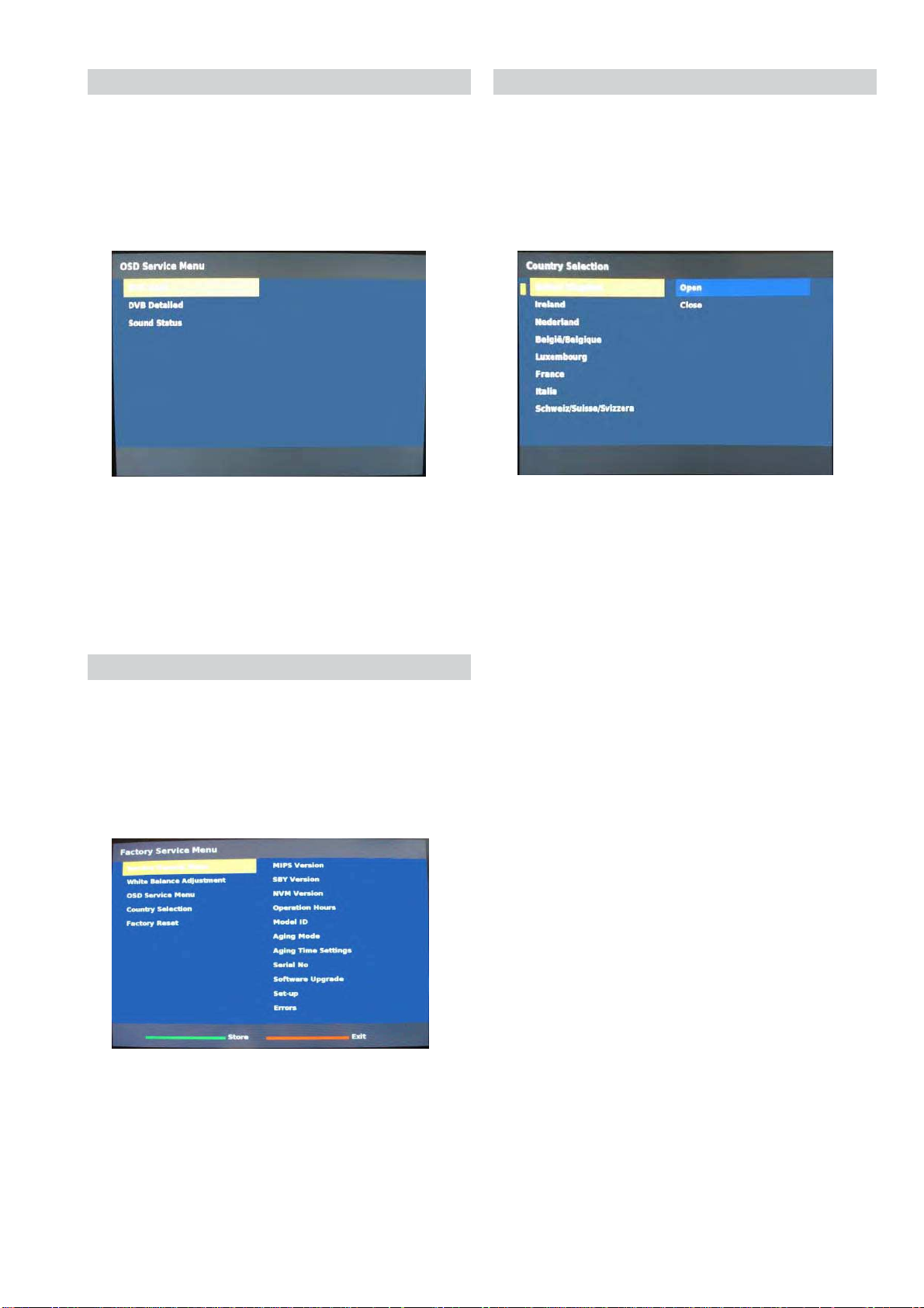
3-2-1. Service General Menu
The following menu appears on the screen when you enter
the ‘Service General Menu’ (See Pic.2). This menu allows
you to view the product information, set the TV into Aging
Mode and perform Software Upgrade to the TV set.
3-2-2. White Balance Adjustment
The following menu appears on the screen when you enter
the ‘White Balance Adjustment’ menu (See Pic.3). This menu
allows adjustment of the TV picture levels. These adjustments
are set during manufacture and should not normally require
further adjustment.
I/
TV
i+
5
+
(ON SCREEN (DIGIT 5) (VOLUME +) (TV)
DISPLAY)
(TV STANDBY)
(ON SCREEN
DISPLAY)
(DIGIT 5) (VOLUME +)
Page 15
- 14 -
The following menu appears on the screen when you enter
the ‘OSD Service Menu’ (See Pic.4). This menu allows
viewing and adjustment of the AGC and viewing of the
Sound Status.
3-2-3. OSD Service Menu
Pic.4
The following menu appears on the screen when you enter
the ‘Country Selection’ menu (See Pic.5). Using this menu
the destination country of the TV can be set.
3-2-4. Country Selection
Pic.5
3-2-5. Factory Reset
Pic.6
Selection of ‘Factory Reset’ (See Pic.6) allows the TV to be
reset to factory shipping condition. This will restore all
settings to those which were contained in the TV on first
shipment.
Page 16
- 15 -
The TT modes described below are available by selecting the two
relevant digits. You can exit the ‘TT Mode’ by entering 00, by
pressing the ‘Analog’ or the ‘Digital’ button, by switching the TV
set into Stand-by mode, or by Powering the TV set off.
3-3. TT MODE
00
'TT' mode off
03
Set volume to 35%
04
Set volume to 50%
05
Set volume to 65%
06
Set volume to 80%
07
Ageing mode on
08
Shipping Condition
09
WB Levels Check
19
Factory toggle mode (ON/OFF)
27
CBA mode toggle (ON/OFF)
31
ECS mode toggle (ON/OFF)
32
Set BCN channels preset
36
Full HD HDMI EDID Write
37
WXGA HDMI EDID Write
41
Re-initialise NVM
43
Select Dual Sound "A"
44
Select Dual Sound "B"
45
Select Dual Sound "Mono"
46
Select Dual Sound "Stereo"
48
Set NVM as non-virgin
49
Set NVM as virgin
59
Stop Main IIC Micro
69
WXGA /FHD Panel Selection
75
Set Centred Balance
76
Set Volume to Max
77
Set Volume to Min
78
Set Balance Full Left
79
Set Balance Full Right
81
Digital BER Display
84
TS CI Path Through
87
Front Panel Button Test
89
LED Test
92
TS CI Path Through With Reed Solomon Off
Note :
To place the Remote Commander in ‘TT Mode’ press the
following buttons together for approximately five seconds.
To use the Remote Commander in ‘TT Mode’ press the
‘Red’ text button on the Remote Commander twice.
TT will then appear in the bottom right hand corner of the TV.
i+
5
+
(ON SCREEN (DIGIT 5) (VOLUME +) (TV)
DISPLAY)
(ON SCREEN
DISPLAY)
(DIGIT 5) (VOLUME +)
(EXTERNAL INPUT) (DIGIT 5) (VOLUME +)
To take the Remote Commander out of ‘TT Mode’ press the
same buttons together for approximately five seconds.
TT Button
Page 17
- 16 -
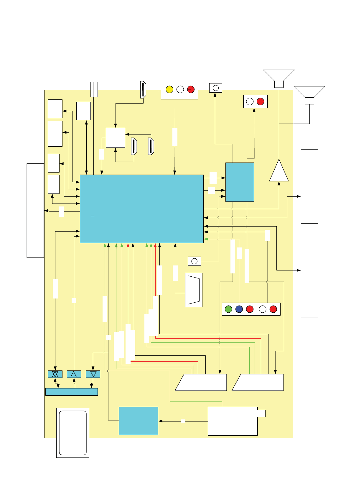
4-1. BLOCK DIAGRAM
CA module
Main Processor
AV Switch
Color Decoder
3D Comb
PC/HD ADC
Audio Decoder
MPEG2 Decoder
4-Field MADI
Scaler
Noise Reduction
HDMI/DVI with HDCP
CI
Dual LVDS
USB2.0
Full Audio Process
10 bit Video Process
SCART 1 SCART 2
D
V
B-T
D
E
M
O
D
U
L
A
T
O
R
HDMI 2
Component
PC
TUNER
HDMI 1
HDMI 3
IF
TS
Line Out
Headphones
USB
PANEL
LVDS
PC/DVI
audio
SCART1_RGB
SCART1_CVBS_OUT
SCART1_LR_IN
SCART1_CVBS
SCART2_CVBS
SCART2_RGB
SCART2_CVBS_OUT
SCART2_LR_IN
SCART1_LR_OUT
YPbPr
LR_IN
HDMI
SWITCH
HDMI
CVBS_LR
RGB/HV
LAST RF
OUT
MON
OUT
Audio
Amp
L Speaker
R Speaker
CI connector
TS
CONTROL
DDR2 DDR2
NAND
FLASH
SPI
KEYBOARD
IR/LED BOARD
CVBS TUNER
A
U
D
I
O S
W
I
T
C
H
+
A
U
D
I
O B
U
F
F
E
R
SCART2_LR_OUT
NVM
Page 18
- 17 -
5-2. CIRCUIT BOARD LOCATION
5-3. SCHEMATIC DIAGRAMS AND
PRINTED WIRING BOARDS
Note :
•All capacitors are in µF unless otherwise noted.
•pF : µµF 50WV or less are not indicated except for
electrolytic types.
•Indication of resistance, which does not have one for
rating electrical power, is as follows.
Pitch : 5mm
Electrical power rating : 1/4W
•Chip resistors are 1/10W
• All resistors are in ohms.
k = 1000 ohms, M = 1000,000 ohms
• : nonflammable resistor.
• : fusible resistor.
• : internal component.
• : panel designation or adjustment for repair.
• All variable and adjustable resistors have
characteristic curve B, unless otherwise noted.
•All voltages are in Volts.
•Readings are taken with a 10Mohm digital mutimeter.
•Readings are taken with a color bar input signal.
•Voltage variations may be noted due to normal production
tolerences.
• : B + bus.
• : B - bus.
• : RF signal path.
• : earth - ground.
• : earth - chassis.
Reference Information
RESISTOR RN
: METAL FILM
RC
: SOLID
FPRD
: NON FLAMMABLE CARBON
FUSE
: NON FLAMMABLE FUSIBLE
RS
: NON FLAMMABLE METAL OXIDE
RB
: NON FLAMMABLE CEMENT
RW
: NON FLAMMABLE WIREWOUND
: ADJUSTMENT RESISTOR
COIL LF-8L
: MICRO INDUCTOR
CAPACITOR TA
: TANTALUM
PS
: STYROL
PP
: POLYPROPYLENE
PT
: MYLAR
MPS
: METALIZED POLYESTER
MPP
: METALIZED POLYPROPYLENE
ALB
: BIPOLAR
ALT
: HIGH TEMPERATURE
ALR
: HIGH RIPPLE
Les composants identifiés par une trame et
par une marque sont d'une importance
critique pour la sécurité. Ne les remplacer
que par des pièces de numéro spécifié.
specified.
Note :
The components identified by shading
and marked are critical for safety.
Replace only with the part numbers
specified in the parts list.
Note :
CVM Board
A Board
S1 Board
VM
C
H
D1
A
J
A2
N
D
A1
D2
C
A
4-2. CIRCUIT BOARD LOCATION
4-3. SCHEMATIC DIAGRAMS AND
PRINTED WIRING BOARDS
Note :
The components identified by mark
contain
confidential information.
Strictly follow the instructions whenever the
components are repaired and/or replaced.
NOTE: The G2 and G4 boards are not Sony boards so their schematic diagrams and
printed wiring boards are not shown in this Service Manual.
Schematic diagrams are for reference only. Please refer to the electrical parts
list for the correct value and part number of components.
G2 / G4 / IP1F
B
H1
Page 19

- 18 -
DDCCBB
O
P
EE
FF
Z
10
A B C D E F G H JI K L M N
1
2
3
4
5
6
7
8
9
1
2
3
4
5
6
7
8
9
11
10
11
22
21
22
R
Q
O
P
EE
FF
S
T
U
V
W
X
Y
Z
AA
BB
CC
DD
A B C D E F G H JI K L M N
12
13
14
15
16
17
18
19
20
21
20
18
19
17
15
16
14
12
13
Q R S T U V W X Y AA
~ B Board Schematic Diagram [ Tuner, Main Microcontroller, HDMI/AV Input/PC Input, Scarts ] Page 1/12 ~
+3V3_STANDBY
1005
1/16W
CHIP
5%
R6016
47k
SUPPLY_FAULT_NEG
1005
1/16W
CHIP
5%
R6018
10k
1
PZU5.6B2
D6004
+3V3
1/16W
CHIP
5%
330k
R6038
XX
C6019
PZU5.6B2
D6005
CHIP
10k
R6043
1/16W
5%
1/16W
CHIP
330k
R6050
5%
1/16W
CHIP
5%
100
R6025
JL6008
PZU5.6B2
D6008
XX
R6036
1/16W
CHIP
5%
10k
R6048
XX
C6008
JL6012
SUPPLY_FAULT_NEG
XX
R6034
INV_FAULT
JL6011
1/16W
CHIP
5%
3.3k
R6033
1/16W
RN-CP
68k
R6049
0.5%
SUPPLY_FAULT
1/16W
CHIP
10k
R6042
5%
1/16W
CHIP
2.2k
R6045
5%
XX
C6005
XX
R6035
CTRL1_STBY_LAMP_ON
+3V3
BACKLIGHT_OUT
1005
6.3V
1
X6S
C6012
S
2SK2036(TE85L)
Q6009
1/10W
RN-CP
5%
100
R6054
+3V3
LAMP_ON_OUT
XX
R6041
1/16W
CHIP
5%
10k
R6039
+3V3
BAL_ERR
ON_MODE
XX
R6120
1/16W
CHIP
5%
1k
R6121
1/16W
CHIP
5%
2.2k
R6021
D6019XXD6018
XX
+3V3_STANDBY
POWERON
1/16W
CHIP
5%
10k
R6010
+5V_ON
GPIO_0
XX
R6011
+5V_ON
XX
C6003
PWM0
XX
C6000
BRT_ADJ
1005
CHIP
R6020
0
*R6027
XX
*R6029
XX
1
C6028
1
C6009
+3V3
JL6015
+12V
*R60300*R6031
0
*R6032
0
0.1
C6010
*R6028
XX
+5V_PANEL
1/16W
CHIP
5%
10k
R6044
1/16W
CHIP
5%
10k
R6040
1/16W
CHIP
5%
4.7k
R6046
1/16W
CHIP
5%
47
R6047
JL6013
+3V3
CTRL1_MIPS_LCD_PWR_ON
POWERON
JL6004
JL6005
SUPPLY_FAULT
JL6003
+12V
LAMP_ON_OUT
JL6000
XX
R6019
BACKLIGHT_OUT
1 2345
PQ200WNA1ZPH
IC6003
+12V
XX
R6063
JL6019
XX
R6064
ENABLE_3V3
XX
C6057
XX
C6059
0uH
FB6009
12345
PQ070XNA1ZPH
IC6008
XX
C6088
+5V_TUN
VDDA_AUDIO
JL6026
JL6028
JL6018
8765
4321
MP2303DN-LF-Z
IC6004
321616V10 X6S
C6048
321616V10 X6SC6049
+12V
1005
16V
0.1
C6039
XX
R6070
XX
R6062
1005
25V
0.01
X7R
C6031
ENABLE_3V3
1005
25V
0.01
X7R
C6044
M1FM3
D6010
1/16W
RN-CP
0.5%
10k
R6082
XX
C6076
+5V
JL6020
JL6021
+12V
M1FM3
D6011
+3V3
3216
16V
10
X6S
C6050
8765
4321
MP2303DN-LF-Z
IC6005
1005
16V
0.1
C6040
1005
25V
0.01
X7R
C6032
3216
16V
10
X6S
C6051
XX
C6083
ENABLE_3V3
1005
25V
0.01
X7R
C6045
XX
C6036
R6071
XX
XX
C6073
XX
C6077
XX
C6080
XX
C6097
12345
PQ070XNA1ZPH
IC6009
+1V8
1005
6.3V
1
X6S
C6099
1608
16V
0.47
X7R
C6101
+1V3_VID
JL6029
JL6027
1005
16V
0.1
C6042
ENABLE_1V2
M1FM3
D6013
XX
C6075
+1V2
3216
16V
10
X6S
C6054
XX
C6085
XX
C6079
XX
C6038
1005
25V
0.01
X7R
C6047
3216
16V
10
X6S
C6055
+12V
XX
C6082
R6073
XX
8 765
4321
MP2303DN-LF-Z
IC6007
JL6024
XX
C6089
XX
C6087
1/16W
CHIP
5%
10k
R6069
1005
6.3V
1
X6S
C6001
+1V2_STANDBY
JL6010
54
321
MM3141CNRE
IC6001
1608
16V
0.47
X7R
C6007
+3V3_STANDBY
+3V3_STANDBY
3.15A
PS6001
3.15A
PS6002
3.15A
PS6003
3.15A
PS6005
1/16W
RN-CP
0.5%
22k
R6074
1/16W
RN-CP
0.5%
10k
R6075
XX
R6076
1/16W
RN-CP
0.5%
22k
R6092
1/16W
RN-CP
0.5%
68k
R6091
XX
R6093
1608
16V
1
X7R
C6086
0uH
L6005
0uH
L6006
+5V_CA
+5V_ON
JL6023
JL6022
1/16W
RN-CP
0.5%
15k
R6083
1/16W
RN-CP
0.5%
4.7k
R6084
XX
R6077
1/16W
RN-CP
0.5%
22k
R6107
1/16W
RN-CP
0.5%
47k
R6108
XX
R6106
XX
R6087
654
321
DDG
SDD
RTQ035P02TR
Q6012
16V
470
C6002
0uH
FB6004
0uH
FB6005
0uH
FB6006
0uH
FB6008
VDISP
JL6016
12V_UNREG_AUDIO
+5V_PANEL
3.15A
PS6000
+3V3_STANDBY
JL6006
POWER_DET
1/16W
CHIP
5%
10k
R6002
1/16W
CHIP
5%
10k
R6003
MA4J1130GLS0
D6000
+5V
+5V_TUN
VDDA_AUDIO
MA4J1130GLS0
D6001
+3V3
+1V8
2SC5950G0LS0
Q6004
2SC5950G0LS0
Q6010
Q6003
XX
Q6014
XX
Q6002
XX
2SA2122G0LS0
Q6013
Q6006
XX
2SC5950G0LS0
Q6007
2SC5950G0LS0
Q6008
MA2J1110GLS0
D6006
JL6002
JL6007
10 9876
54321
LA5795T-TLM-E
IC6002
2012
10V
4.7
X7R
C6014
1005
50V
100p
CH
C6015
D6009
XX
3216
50V
2.2
X7R
C6020
1608
50V
0.1
X7R
C6027
XX
C6025
XX
C6024
XX
C6017
50V
4.7
C6029
XX
C6023
XX
C6026
XX
C6030
XX
C6016
+5V_TUN_33V
+33V
JL6017
JL6014
JL6009
0uH
FB6000
0uH
FB6003
LFBK1608HS601
0uH
FB6001
0uH
FB6002
LFBK1608HS601
2012
25V
1
C6022
X7R
2012
25V
1
C6021
X7R
2012
25V
1
C6018
X7R
54
321
MM3143DNRE
IC6010
1005
6.3V
1
X6S
C6096
1608
16V
0.47
X7R
C6100
C6011
XX
D6007
XX
8 765
4321
S1 S2 S3 G
D1D2D3D4
Q6011
XX
R6055
XX
8 765
4321
LM393DT (A)
IC6000
1005
16V
0.1
C6004
+12V
1/16W
CHIP
5%
56k
R6012
1/16W
CHIP
5%
4.7k
R6014
1/16W
CHIP
5%
100
R6000
1005
16V
0.1
C6006
+1V2
+1V3_VID
MA4J1130GLS0
D6002
1/16W
CHIP
5%
10k
R6122
JL6030
1/16W
CHIP
5%
10k
R6123
XX
R6117
1/16W
CHIP
5%
10k
R6116
XX
C6102
XX
C6103
XX
C6104
PZU5.6B2
D6020
6.3V
330
C6105
VD6001
16V
47
C6091
16V
47
C6092
10uH
L6001
10uH
L6002
JL6031JL6001
JL6032
JL6033
JL6034
JL6035
JL6036
JL6037
JL6038
JL6039
JL6040
JL6041
JL6042
JL6043
XX
R6004
XX
R6009
2012
10V
10
X6S
C6060
2012
10V
10
X6S
C6061
2012
10V
10
X6S
C6063
2012
10V
10
X6S
C6064
2012
10V
10
X6S
C6065
2012
10V
10
X6S
C6067
2012
10V
10
X6S
C6068
2012
10V
10
X6S
C6069
2012
10V
10
X6S
C6071
KDZTR5.6B
D6014
KDZTR3.9B
D6015
KDZTR3.9B
D6017
2SA2122G0LS0
Q6000
XX
R6078
24V
5A
F6000
123456789
101112131415161718192021222324252627282930
30P
CN6000
WHT
POWER_ON
AC_OFF_DET
STBY3V3
UNREG_15V
UNREG_15V
UNREG_15V_GND
UNREG_15V_GND
REG_12V_GND
REG_12V_GND
REG_12V_GND
REG_12V
REG_12V
REG_12V
BALANCER_ERR
GND
INV_ERR
LAMP_ON/OFF
DIMMER
+5V_PANEL
GND
+3V3_STANDBY
GND
REC_LED
LED1
LED3
LED2
LED4
BL_IN
+3V3
RC
6.3V
22
C4107
D4105
XX
CL4102
FB4105
XX
FB4103
0uH
JL4107
FB4102
0uH
JL4104
LED1
RC
SUPPLY_FAULT_NEG
LED3
FB4106
0uH
LED4
JL4106
D4100
XX
VD4103
JL4114
D4101
XX
LED2
JL4111
FB4104
0uH
JL4113
C4103
220p
50V
X7R
1005
FB4107
0uH
JL4112
+3V3_STANDBY
Q4100
XX
JL4105
JL4110
CHIP
0
R6135
CHIP
0
R6136
CHIP
0
R6137
1005
1/16W
RN-CP
0.5%
R6138
12k
CHIP
0
R6139
CHIP
0
R6140
CHIP
0
R6141
CHIP
0
R6142
CHIP
0
R6143
CHIP
0
R6144
XX
R6145
54
321
MM3291CNRE
IC6011
XX
C6106
CHIP
0
R6061
1005
CHIP
R6065
0
CHIP
0
R6066
CHIP
0
R6068
CHIP
0
R6124
CHIP
0
R6125
CHIP
0
R6126
4.7uH
L6004
PZU5.6B2
D6021
PZU5.6B2
D6022
XX
R6146
100nH
L6000
1608
16V
1
C6043
X7R
1608
16V
1
C6072
X7R
3216
16V
10
C6056
X6S
2012
10V
10
C6090
X6S
1005
6.3V
1
C6093
X6S
2012
6.3V
10
C6098
X6S
2012
10V
10
X6S
C6107
2012
10V
10
X6S
C6108
2012
10V
10
X6S
C6109
1608
16V
X7R
C6013
1
1005
25V
0.022
X7R
C6034
XX
C6035
1/16W
CHIP
5%
15k
R6058
1/16W
CHIP
5%
22k
R6060
1005
1/16W
CHIP
5%
R6026
10k
CHIP
0
R6089
CHIP
0
R6090
GND_AU
XX
C6110
XX
C6111
XX
C6112
XX
C6113
XX
C6114
XX
C6115
XX
C6116
XX
C6117
XX
C6118
XX
C6119
XX
C6120
XX
C6121
UNR52A3G0LS0
Q6001
UNR52A3G0LS0
Q6005
CHIP
0
R6147
CHIP
0
R6148
+1V2FB
JL6044
JL6045
PZU5.6B2
D6023
PZU5.6B2
D6024
1/16W
CHIP
5%
100
R6149
JL6046
2.2k
*R6005
1k
*R6007
33k
*R6052
68k
*R6053
JL6047
CHIP
0
R6037
4.7k
R6017
RN-CP
3.3
R6128
1/10W
5%
1/16W
RN-CP
0.5%
3.3k
R6057
1/16W
0.5%
68k
R6079
1/16W
RN-CP
0.5%
47k
R6081
1/16W
RN-CP
0.5%
22k
R6088
0uH
FB6010
POWER_DET
+1V2_ST ANDBY
33V TUNER VCC
B
B-EX2N
COMPONENTS MARKED AS XX REFER TO PARTS LIST, WILL ONLY BE LISTED IF FITTED
1/12 TUNER, MAIN MICROCONTROLLER, HDMI/AV SIDE/PC INPUT, SCARTS
Page 20

- 19 -
DDCCBB
O
P
EE
FF
Z
10
A B C D E F G H JI K L M N
1
2
3
4
5
6
7
8
9
1
2
3
4
5
6
7
8
9
11
10
11
22
21
22
R
Q
O
P
EE
FF
S
T
U
V
W
X
Y
Z
AA
BB
CC
DD
A B C D E F G H JI K L M N
12
13
14
15
16
17
18
19
20
21
20
18
19
17
15
16
14
12
13
Q R S T U V W X Y AA
~ B Board Schematic Diagram [ Tuner, Main Microcontroller, HDMI/AV Input/PC Input, Scarts ] Page 2/12 ~
JL3001
1608
50V
1000p
CH
C3010
1/10W
RN-CP
1k
R3007
1/10W
RN-CP
1k
R3008
1/10W
RN-CP
470k
R3013
GND_1
GND_1
1608
50V
CH
C3004
100p
SIDE_IO_LEFT
SIDE_IO_RIGHT
GND_1
1/10W
RN-CP
470k
R3012
GND_1
JL3002
GND_1
AV6_CVBS
GND_1
1608
50V
CH
C3005
100p
1608
50V
1000p
CH
C3009
GND_1
GND_1
1005
1/16W
CHIP
5%
R3003
330
AUDIO_HDPH_L_AP
1005
50V
X7R
C3000
330p
1005
50V
X7R
C3001
330p
GND_AU
1005
1/16W
CHIP
5%
R3005
330
AUDIO_HDPH_R_AP
1/10W
RN-CP
470k
R3061
JL3027
AV3_YPBPR_PB
AV3_YPBPR_PR
AV3_YPBPR_RIGHT
1005
1/16W
CHIP
5%
R3070
1k
AV3_YPBPR_LEFT
1608
50V
1000p
C3038
CH
1005
1/16W
CHIP
5%
R3073
1k
1608
50V
1000p
C3037
CH
1/10W
RN-CP
470k
R3060
JL3029
AV3_YPBPR_Y
JL3028
1/10W
RN-CP
470k
R3044
XX
R3041
XX
R3049
AV2_STATUS
JL3010
1005
1/16W
CHIP
5%
R3018
330
1/10W
RN-CP
470k
R3043
470k
R3054
1/10W
RN-CP
470k
R3042
AV1_RIGHT
AV2_RGB_B
1005
1/16W
CHIP
5%
R3031
330
1/10W
RN-CP
150
R3062
0.1
C3041
1005
1/16W
CHIP
5%
R3030
1k
AV2_CVBS/Y
1/10W
RN-CP
470k
R3045
2012
6.3V
10
X6S
C3039
470k
R3051
XX
R3033
AV1_RGB_R/C
+5V
R3035
RN-CP
220
1/10W
JL3016
1/10W
RN-CP
470
R3064
1005
1/16W
CHIP
5%
R3019
330
AV1_LEFT
1/10W
RN-CP
10k
R3069
AUDIO_OUT_RIGHT
1/10W
RN-CP
150
R3065
JL3019
AV1_CVBS/Y
1608
50V
1000p
C3019
CH
1005
1/16W
CHIP
5%
R3015
1k
AV1_RGB_B
CVBS_TER_OUT
1608
50V
1000p
C3017
CH
JL3031
150
R3063
JL3005
JL3006
JL3018
AV2_RGB_G
1000p
C3022
XX
R3026
XX
R3023
XX
R3022
XX
R3021
AV2_RGB_R/C
JL3009
1005
1/16W
CHIP
5%
R3032
330
10k
R3072
JL3022
10
C3042
470
R3066
AUDIO_OUT_LEFT
+5V
JL3026
Y_CVBS_MON_OUT
XX
R3024
1005
1/16W
CHIP
5%
R3017
1k
AV2_RIGHT
JL3030
XX
R3025
AV1_RGB_G
R3036
RN-CP
220
1/10W
150
R3067
JL3021
AV2_LEFT
1608
25V
0.1
X7R
C3040
AV1_STATUS
JL3017
MONITOR_OUT_LEFT
JL3025
XX
R3020
470k
R3052
1000p
C3024
JL3015
JL3008
1005
1/16W
CHI
P
5%
R3029
1k
JL3020
JL3007
MONITOR_OUT_RIGHT
470k
R3053
JL3023
1005
50V
100p
CH
C3015
1/16W
RN-CP
0.5%
1k
R3027
1/16W
RN-CP
0.5%
470k
R3040
1/16W
RN-CP
0.5%
47k
R3055
AV2_BLK
+3V3
1/16W
RN-CP
0.5%
1k
R3037
AV1_BLK
XX
R3058
+3V3
1005
50V
100p
CH
C3020
1/16W
RN-CP
0.5%
470k
R3050
R3048
XX
AV2_AVLINK
JL3024
1/16W
RN-CP
0.5%
3.3k
R3039
1/16W
RN-CP
0.5%
3.3k
R3034
AUDIO_HDPH_R_AP
AUDIO_HDPH_L_AP
1005
50V
0.001
X7R
C3011
1005
50V
100p
CH
C3007
1005
50V
100p
CH
C3008
1005
50V
0.001
X7R
C3012
CHIP
0
R3009
CHIP
0
R3010
HP_DET
GND_AU
HPBIASOUT
020:16H
XX
R3014
XX
R3011
GND_1
1/16W
RN-CP
18k
R3068
18k
R3071
XX
R3002
2SC5950G0LS0
Q3001
2SC5950G0LS0
Q3007
2SC5950G0LS0
Q3000
2SC5950G0LS0
Q3006
Q3005
2SA2122G0LS0
Q3004
CVBS_LAST_RF
XX
R3074
XX
C3003
XX
C3002
JL3000
GND_1
VD3000
XX
AV1_CVBS/Y
R9901
XX
Q9807
XX
VD9809
XX
XX
R9816
XX
R9864
XX
R9809
XX
R9863
MONITOR_OUT_LEFT
XX
C9807
GND_1
XX
FB9803
R9909
XX
VD9810
XX
Q9809
XX
XX
R9891
AV1_RGB_B
GND_1
GND_1
R9907
XX
VD9804
XX
AV1_RIGHT
R9911
XX
R9910
XX
GND_1
GND_1
R9912
XX
AV1_RGB_R/C
R9900
XX
C9838
XX
GND_1
R9810
XX
R9808
XX
VD9811
XX
AV2_RGB_R/C
Y_VIDEO1
MONITOR_OUT_RIGHT
AV2_CVBS/Y
GND_1
GND_1
R9902
XX
VD9842
XX
GND_1
R9908
XX
R9872
XX
XX
C9808
AV2_LEFT
GND_1
VD9847
XX
VD9802
XX
VD9843
XX
AV1_LEFT
GND_1
VD9841
XX
R9906
XX
R9871
XX
AV1_RGB_G
GND_1
GND_1
R9904
XX
XX
R9892
AV2_RIGHT
R9913
XX
R9905
XX
GND_1
Q9808
XX
GND_1
XX
R9865
R9903
XX
XX
R9893
R9815
XX
XX
R9916
+5V
AV1_BLK
XX
R3098
Q9810
XX
Y_CVBS_MON_OUT
R9914
XX
VID_IO_SEL
C9837
XX
C9800
XX
+3V3
GND_1
1005
50V
CH
C3021
100p
1005
50V
CH
C3023
100p
1005
50V
CH
C3016
100p
1005
50V
CH
C3018
100p
VD3036
VD3001
VD3002
VD3003
VD3004
VD3006
VD3007
VD3008
VD3009
VD3010
VD3011
VD3012
VD3013
VD3014
VD3015
VD3017
VD3016
VD3018
VD3019VD3020
VD3021
XX
VD3022
VD3023
VD3024
VD3025
VD3026
VD3027
VD3028
JL3013
JL3011
JL3012
VD3029
VD3030
VD3031
VD3032
VD3033
VD3034
VD3035
1005
6.3V
1
X6S
C3025
1005
6.3V
1
X6S
C3028
1/16W
RN-CP
0.5%
75
R3028
75
R3046
1/16W
RN-CP
0.5%
75
R3038
1/16
W
RN-CP
0.5%
1/16W
RN-CP
0.5%
75
R3016
L
R
VBVGVR
J9801
XX
J3002
L
R
V
J9802
XX
12
34
XX
C3006
42P
CN3000
123456789101112131415161718192021
222324252627282930313233343536373839404142
2SC5950G0LS0
Q3002
2SC5950G0LS0
Q3003
1/16W
RN-CP
0.5%
470k
R3047
1/16W
RN-CP
0.5%
470k
R3056
1005
25V
0.01
X7R
C3043
1005
25V
0.01
X7R
C3044
XX
R9928
XX
R9929
XX
R9930
XX
R9931
XX
R9932
D9801
XX
Q9811
XX
XX
R9933
L
R
V
J3000
P5P6P7P8P9
P1P3P2
P4
P10
P11
P12
P13
P14
P15
P16
VD3037
XX
VD3005
XX
XX
C3013XXC3014
GND_AU
XX
R3057
XX
R3059
XX
R3075
XX
R3076
XX
R3077
XX
R3078
GND_AU
GND_AU
L
R
J3001
1005
1/16W
CHIP
5%
R3079
100
1005
1/16W
CHIP
5%
R3080
100
CHIP
100
R3004
1/16W
5%
CHIP
100
R3006
1/16W
5%
AV2_RIGHT
AV2_LEFT
LATERAL A/V CONNECTOR
AUDIO OUT
LINE OUT
COMPONENT INPUT
AV1
SCART1
AV2
SCART2
HP
SCART1‚ÆSCART2 ªzu
AEP ¨O }Eg
COMPONENT & CVBS INPUT
CVBS INPUT & OUTPUT
Y/C INPUT
B
COMPONENTS MARKED AS XX REFER TO PARTS LIST, WILL ONLY BE LISTED IF FITTED
2/12
Page 21

- 20 -
DDCCBB
O
P
EE
FF
Z
10
A B C D E F G H JI K L M N
1
2
3
4
5
6
7
8
9
1
2
3
4
5
6
7
8
9
11
10
11
22
21
22
R
Q
O
P
EE
FF
S
T
U
V
W
X
Y
Z
AA
BB
CC
DD
A B C D E F G H JI K L M N
12
13
14
15
16
17
18
19
20
21
20
18
19
17
15
16
14
12
13
Q R S T U V W X Y AA
~ B Board Schematic Diagram [ Tuner, Main Microcontroller, HDMI/AV Input/PC Input, Scarts ] Page 3/12 ~
JL4500
H_SYNC_VGA
JL4504
10k
R4507
B_VGA
JL4503
10k
R4508
V_SYNC_VGA
JL4502
8 765
4321
IC4500
E0E1E2
VSS SDA
SCL
WC
VCC
JL4507
100k
R4518
2.2k
R4517
EEPROM_WP
R_VGA
JL4505
+5V
0
R4505
G_VGA
0.1
C4500
JL4508
0.5A
F4500
JL4501
JL4506
1/16W
CHIP
5%
100
R4525
1/16W
CHIP
5%
100
R4526
EEPROM_WP
SDA_HDMI1
SCL_HDMI1
27k
R5521
S
Q5500
CEC
VD5502
XX
D5500
XX
XX
R5501
R5525
XX
CEC_HDMI
JL5500
HPD1
XX
R5522
8765
4321
IC5500
XX
A1A0A2
ESDA
SCL
WP
VCC
+5V
CL5501
D5505
XX
XX
FB5500
XX
R5500
XX
C5503
JL5512
JL5508
XX
R5523
CEC
+3V3_STANDBY
JL5504
VD5500
XX
Q5501
XX
+3V3_HDMI
EMI
FL5501
+1V8_HDMI
XX
C5525
XX
C5523
1005
16V
C5515
0.1
0.1
C5529
XX
C5509
1005
16V
C5518
0.1
0.1
C5526
0.1
C5528
XX
C5510
XX
C5520
1005
16V
C5522
0.1
EMI
FL5500
C5516
XX
0.1
C5514
1005
16V
C5524
0.1
1005
16V
C5521
0.1
DDC+5V_1
HDMI1_CLK-
HDMI1_CLK+
HDMI1_D0-
HDMI1_D0+
HDMI1_D1-
HDMI1_D1+
HDMI1_D2-
HDMI1_D2+
DDC+5V_1
CL5522
D5510
XX
D5509
XX
+3V3
+1V8
XX
C5517
0.1
C5519
0.1
C5527
0.1
C5500
RX0+
RX0-
RX1+
RX1-
RX2+
RX2-
RXC+
RXC-
DDC_SCL
DDC_SDA
+1V8_HDMI
+1V8_HDMI
+3V3_HDMI
+3V3_HDMI
RXC+
RXC-
DDC_SCL
DDC_SDA
RX0-
RX0+
RX1-
RX1+
RX2-
RX2+
0.1
C5507
HDMI1_D0-
HDMI1_D0+
HDMI1_CLK+
HDMI1_CLK-
HDMI1_D1+
HDMI1_D1-
HDMI1_D2+
HDMI1_D2-
HDMI2_CLK-
HDMI2_CLK+
HDMI2_D0-
HDMI2_D0+
HDMI2_D1+
HDMI2_D1-
HDMI2_D2+
HDMI2_D2-
0.1
C5508
+1V8_HDMI
SDA_SSB
SCL_SSB
CL5517
0.1
C5506
CEC
HPD3
XX
R5506
HDMI2_CLK+
SCL_HDMI2
*VD5501
XX
XX
*FB5501
JL5513
HDMI2_D1+
8765
4321
*IC5501
XX
A1A0A2
E SDA
SCL
WP
VCC
JL5507
*D5501
XX
HDMI2_D0-
DDC+5V_2
XX
*R5502
EEPROM_WP
XX
*C5504
XX
*R5503
CL5503
HDMI2_D2-
HDMI2_D0+
CEC
0.1
*C5501
*D5506
XX
HDMI2_CLK-
SDA_HDMI2
HPD2
HDMI2_D2+
JL5509
XX
*R5507
HDMI2_D1-
*VD5503
XX
JL5502
VD5504
XX
SCL_HDMI3
XX
R5504
D5508
XX
HDMI3_D2-
HDMI3_D0+
XX
R5508
0.1
C5502
HDMI3_D2+
EEPROM_WP
HDMI3_CLK-
HDMI3_D1-
JL5511
HDMI3_CLK+
CEC
D5504
XX
JL5505
SDA_HDMI3
XX
R5505
XX
FB5502
JL5510
HDMI3_D0-
VD5505
XX
HDMI3_D1+
JL5514
JL5506
HPD3
DDC+5V_3
XX
C5505
8 765
4321
IC5502
XX
A1A0A2
ESDA
SCL
WP
VCC
HPD1
DDC+5V_1
SDA_HDMI1
SCL_HDMI1
+3V3_HDMI
1/16W
RN-CP
0.5%
12k
R5511
+3V3_HDMI
HDMI3_D2+
HDMI3_D2-
HDMI3_D1+
HDMI3_D1-
HDMI3_D0+
HDMI3_D0-
HDMI3_CLK+
HDMI3_CLK-
SCL_HDMI3
SDA_HDMI3
DDC+5V_3
+3V3_HDMI
+3V3_STANDBY
1/16W
CHIP
5%
4.7k
R5515
XX
R5519
+3V3_HDMI
CL5518
CL5519
SCL_HDMI2
SDA_HDMI2
DDC+5V_2
HPD2
+5V_ON
1/16W
RN-CP
0.5%
1.8k
R5510
1/16W
RN-CP
0.5%
1.8k
R5509
47k
RB5500
DDC+5V_1
47K
RB5501
DDC+5V_3
DDC+5V_2
CL5520
CL5521
RREF_PNX8535
1/16W
12k
R5524
CHIP
5%
D5502
XX
*D5503
XX
+5V
DDC+5V_2
+5V
DDC+5V_3
D5507
XX
MA4J1130GLS0
D4502
CHIP
0
R5513
XX
R5514
CHIP
0
R5512
100
RB5502
2012
6.3V
22
X6S
C5512
2012
6.3V
10
X6S
C5511
1/16W
CHIP
5%
10k
R5526
+3V3
CL5523
JL5515
JL5516
0.1
C5513
1/16W
CHIP
5%
22k
R5527
2SA2122G0LS0
Q5502
1/16W
CHIP
5%
100
R5529
1005
16V
0.1
C5530
MA2J1110GLS0
D5511
MA2J1110GLS0
D5512
1005
6.3V
1
X6S
C5531
1/16W
CHIP
5%
10k
R5530
XX
R5531
2SA2122G0LS0
Q5503
+3V3_STANDBY
1005
16V
0.1
C5532
XX
R5533
XX
C5534
XX
R5540
XX
R5538
D5514
XX
XX
R5532
XX
C5533
Q5505
XX
XX
R5539
Q5504
XX
D5513
XX
PC_SYNC_DET
VD5512
XX
CHIP
0
R5535
0
*R5536
*VD5513
XX
VD5514
XX
CHIP
0
R5537
VD4501
VD4502
VD4503
VD4504
VD4505
VD4506
VD4507
VD4508
1/16W
CHIP
5%
47
R4510
1/16W
CHIP
5%
47
R4509
1/16W
CHIP
5%
47
R4500
1/16W
CHIP
5%
47
R4504
1/16W
CHIP
5%
4.7k
R4511
1/16W
CHIP
5%
4.7k
R4506
CL5524
CL5525
CL5526
1/16W
CHIP
5%
4.7k
R5528
1/16W
CHIP
5%
22k
R5534
0uH
FB4500
CHIP
0
R5541
HDMI
PNX85433EH/M2/2008C
IC4000
RX0P_A
B17
RX0N_A
B18
RX1P_A
A16
RX1N_A
A17
RX2P_A
B15
RX2N_A
B16
RXCP_A
A18
RXCN_A
A19
DDC_SCL_A
C18
DDC_SDA_A
E19
RX0P_B
B14
RX0N_B
B13
RX1P_B
A13
RX1N_B
A12
RX2P_B
B12
RX2N_B
B11
RXCP_B
A15
RXCN_B
A14
DDC_SCL_B
C15
DDC_SDA_B
D15
RREF
C16
HOT_PLUG_A
D19
HOT_PLUG_B
E15
12345678910 11 12 13 14 15 16 17 18 19 20 21 22 23 24 25
26272829303132333435363738
3940414243444546474849
50
51525354555657585960616263646566676869707172737475
7677787980818283848586878889909192939495969798
99
100
TDA9995HL/C1
IC5503
Vss
OUT_C+
OUT_C-
VDDO(3V3)
OUT_DDC_CLK
OUT_DDC_DAT
Vss
VDDDC(1V8)
RXA_HPD
RXA_5V
RXA_DDC_DAT
RXA_DDC_CLK
RXA_C-
RXA_C+
VDDH(3V3)
RXA_DO-
RXA_DO+
Vss
RXA_D1-
RXA_D1+
VDDH(3V3)
RXA_D2-
RXA_D2+
VDDH(1V8)
NC
Vss
TEST
RXB_HPD
RXB_5V
RXB_DDC_DAT
RXB_DDC_CLK
RXB_C-
RXB_C+
VDDH(3V3)
RXB_D0-
RXB_D0+
Vss
RXB_D1-
RXB_D1+
VDDH(3V3)
RXB_D2-
RXB_D2+
Vss
CDEC_DDC
VDDDC(1V8)
VDDDC(3V3)
MODE
PD
I2C_SDA/SEL1
I2C_SCL/SEL0
XTAL_IN
XTAL_OUT
INT_N/HP_CTRL
CDEC_STBY
VDD(STB)(3V3)
Vss
CEC
RXC_HPD
RXC_5V
RXC_DDC_DAT
RXC_DDC_CLK
RXC_C-
RXC_C+
VDDH(3V3)
RXC_DO-
RXC_D0+
Vss
RXC_D1-
RXC_D1+
VDDH(3V3)
RXC_D2-
RXC_D2+
Vss
R12K
VDDH(1V8)
NCNCNCNCNCNCVDDH(3V3)NCNC
VssNCNC
VDDH(3V3)NCNC
VDDDC(1V8)
Vss
OUT_D2+
OUT_D2-
VDDO(1V8)
OUT_D1+
OUT_D1-
Vss
OUT_D0+
OUT_D0-
20P
CN5500
1D2+2E3D2-
4D1+5E6D1-
7D0+8E9D0-
10CLK+
11E
12CLK-
13CEC
14NC
15DDC CLK
16DDC DAT
17E
18DDC +5V
19HPD
20
20P
CN5502
1D2+2E3D2-
4D1+5E6D1-
7D0+8E9D0-
10CLK+
11E
12CLK-
13CEC
14NC
15DDC CLK
16DDC DAT
17E
18DDC +5V
19
HPD
20
*CN5501
1D2+2E3D2-
4D1+5E6D1-
7D0+8E9D0-
10CLK+
11E
12CLK-
13CEC
14NC
15DDC CLK
16DDC DAT
17E
18DDC +5V
19HPD
20
1005
50V
220p
X7R
C4501
1005
50V
220p
X7R
C4502
BLK
17P
CN4500
0uH
FB4501
0uH
FB4502
0uH
FB4503
PC INPUT
HDMI 1
HDMI 2
HDMI 3
SIDE
PLACE LANDS OVER TRACKS
COMPONENTS MARKED AS XX REFER TO PARTS LIST, WILL ONLY BE LISTED IF FITTED
B
3/12
Page 22

- 21 -
DDCCBB
O
P
EE
FF
Z
10
A B C D E F G H JI K L M N
1
2
3
4
5
6
7
8
9
1
2
3
4
5
6
7
8
9
11
10
11
22
21
22
R
Q
O
P
EE
FF
S
T
U
V
W
X
Y
Z
AA
BB
CC
DD
A B C D E F G H JI K L M N
12
13
14
15
16
17
18
19
20
21
20
18
19
17
15
16
14
12
13
Q R S T U V W X Y AA
~ B Board Schematic Diagram [ Tuner, Main Microcontroller, HDMI/AV Input/PC Input, Scarts ] Page 4/12 ~
+5V_TUN
16V
100
C2004
16V
100
C2006
6.3V
220
C2005
CHIP
0
R2006
CHIP
0
R2007
CHIP
0
R2008
1005
16V
0.1
C2017
1005
16V
0.1
C2009
1005
16V
0.1
C2010
1005
50V
330p
X7R
C2018
1005
50V
330p
X7R
C2013
1005
50V
330p
X7R
C2014
+5V_TUN_MOPLL
+5V_TUN_33V
+5V_TUN_IF
+5V_TUN_RF_AMP
16V
100
C2003
1005
50V
330p
X7R
C2015
CHIP
0
R2009
1005
16V
0.1
C2011
+5V_TUN_EMI
CL2005
CL2003
CL2004
CL2006
CL2007
CL2008
CL2009
CL2010
CL2011
CL2012
CL2013
CL2014
CL2015
CL2016
CL2017
CL2018
CL2019
CL2020
CL2021
CL2022
CL2023
1005
50V
4700p
X7R
C2071
+5V_TUN_RF_AMP
0.001
C2054
XX
C2050
AGC_MUTE
0.1
C2051
XX
R2050
CHIP
0
R2070
TUN_AGC
CHIP
0
R2063
IF_P
+5V_TUN_MOPLL
XX
R2060
XX
R2065
1005
50V
4700p
X7R
C2073
+5V_TUN_IF_SW
1005
50V
4700p
X7R
C2074
+5V_TUN_MOPLL
CHIP
0
R2074
CHIP
0
R2075
TDA_IF_P
TDA_IF_N
CHIP
0
R2071
TDA_IF_AGC
1uH
L2013
1uH
L2012
1005
50V
330p
X7R
C2056
1005
50V
330p
X7R
C2055
1/16W
CHIP
5%
100
R2049
1/16W
CHIP
5%
100
R2047
+5V_TUN_MOPLL
+5V_TUN_MOPLL
1005
25V
0.01
X7R
C2049
1/16W
RN-CP
0.5%
180
R2044
XX
R2040
CHIP
0
R2039
1005
50V
100p
CH
C2047
1005
50V
100p
CH
C2048
CVBS_TER_OUT
CVBS4_TUNER
+5V_TUN
FE_TUNER_SWB_5V
Q2003
XX
2
5
3
4
1
6
I2C_SW
+5V_TUN_IF
XX
R2005
FE_TUNER_SWB_5V
1005
CHIP
R2004
0
+5V_TUN_IF_SW
1005
50V
0.001
X7R
C2034
3V3DVB_ANA
1005
50V
0.001
X7R
C2038
1V2DVB_ANA
1005
50V
0.001
X7R
C2020
1005
50V
0.001
X7R
C2019
3V3DVB_DIG
1005
50V
0.001
X7R
C2042
1V2DVB_DIG
1005
50V
0.001
X7R
C2031
1005
50V
0.001
X7R
C2039
1005
50V
0.001
X7R
C2043
1005
50V
0.001
X7R
C2044
1005
50V
0.001
X7R
C2045
1005
25V
0.01
X7R
C2035
1005
25V
0.01
X7R
C2036
CHIP
0
R2030
CHIP
0
R2031
XX
C2037
CHIP
0
R2028
CHIP
0
R2032
CHIP
0
R2029
CHIP
0
R2033
TDA_IF_P
TDA_IF_N
1/10W
RN-CP
5%
10k
R2022
1/10W
RN-CP
5%
10k
R2021
3V3DVB_DIG
3V3DVB_DIG
RESET_SYS_DETECT
1005
25V
0.01
X7R
C2033
XX
C2032
33
RB2000
33
RB2004
33
RB2002
FE_DATA7
FE_DATA6
FE_DATA5
FE_DATA4
FE_DATA3
FE_DATA1
FE_DATA0
FE_DATA2
FE_CLK
FE_SOP
FE_V
ALID
+5V_TUN_EMI
1005
16V
0.1
C2000
1/16W
CHIP
5%
1k
R2000
1/10W
RN-CP
5%
10k
R2012
TDA_IF_AGC
1005
16V
0.1
C2008
TUN_AGC
1/16W
CHIP
5%
100k
R2001
XX
R2002
1005
16V
0.1
C2002
1/10W
RN-CP
5%
10k
R2003
1/16W
CHIP
5%
1k
R2010
1/10W
RN-CP
5%
10k
R2014
3V3DVB_ANA
1005
16V
0.1
C2016
1/10W
RN-CP
5%
10k
R2011
1005
16V
0.1
C2007
1/16W
CHIP
5%
1k
R2013
+5V_TUN_EMI
1/16W
CHIP
5%
22
R2024
CL2000
CL2001
CL2002
16MHz
X2000
1005
50V
10p
CH
C2040
1005
50V
10p
CH
C2041
SCL_SSB
SDA_SSB
1/16W
CHIP
5%
100
R2015
1/16W
CHIP
5%
100
R2016
XX
C2022
XX
C2021
TUN_TDA_SDA
TUN_TDA_SCL
3V3DVB_DIG
TUN_TDA_SCL_SW
TUN_TDA_SDA_SW
CHIP
0
R2056
CHIP
0
R2055
1005
50V
68p
CH
C2059
1005
50V
68p
CH
C2060
+1V2_SW
+3V3_SW
1V2DVB_DIG
1V2DVB_ANA
3V3DVB_DIG
3V3DVB_ANA
1005
16V
0.1
C2023
1005
16V
0.1
C2024
1005
16V
0.1
C2025
1005
16V
0.1
C2026
16V
47
C2027
16V
47
C2028
16V
47
C2029
16V
47
C2030
*L2014
XX
*C2065
XX
*C2063
XX
3V3DVB_CABLE_DIG
+3V3_SW
FE_DATA0_QAM
FE_DATA6_QAM
FE_DATA3_QAM
FE_DATA2_QAM
FE_DATA5_QAM
FE_DATA1_QAM
FE_DATA7_QAM
FE_DATA4_QAM
1005
50V
0.001
X7R
C2001
0uH
FB2002
2SC5950G0LS0
Q2011
2SC5950G0LS0
Q2010
0uH
FB2003
Q2001
XX
2SA2122G0LS0
Q2000
2SC5950G0LS0
Q2002
1005
50V
15p
CH
C2046
1/16W
RN-CP
0.5%
1.2k
R2037
1/16W
RN-CP
0.5%
1.2k
R2038
+33V
*C2072
XX
*C2070
XX
*C2080
XX
*C2079
XX
*C2076
XX
*C2081
XX
*R2079
XX
RESET_SYS_DETECT
*C2083
XX
*RB2003
XX
6P25
P1
8P47
P3
4P63
P5
2P81
P7
*RB2005
XX
*RB2001
XX
FE_VALID_QAM
FE_CLK_QAM
FE_SOP_QAM
*C2078
XX
SDA_SSB
SCL_SSB
*R2078
XX
*R2077
XX
*C2077
XX
*C2075
XX
TUN_TDA_SCL
TUN_TDA_SDA
*R2076
XX
*R2073
XX
*R2066
XX
*R2067
XX
*C2052
XX
*R2048
XX
*C2053
XX
*R2052
XX
TDA_IF_AGC
+5V_TUN_EMI
*C2068
XX
*C2069
XX
*R2034
XX
TDA_IF_P_QAM
XX
R2087
XX
R2083
XX
R2084
R2093
XX
XX
R2094
R2085
XX
XX
C2085
SCL_SSB_GRAL
XX
R2092
XX
R2088
XX
C2086
XX
R2091
XX
FB2004
TUN_TDA_SCL_SW
+3V3
XX
L2022
R2082
XX
SDA_SSB_GRAL
14 13 12 11 10 98
7654321
IC2002
XX
QSCL
SILENT_SCL
SILENT_SCL
SCL_ANA
TV_DEM_SEL
TV_DEM_SEL
GND
SDA_ANA
SILIENT_SDA
SILENT_SDA
QSDA
nTV_DEM_SEL
nTV_DEM_SEL
VCC
I2C_SW
R2095
XX
XX
R2089
XX
R2086
XX
R2090
I2C_SW_N
I2C_SW
XX
R2027
1005
CHIP
R2026
0
+3V3_SW
Q2008
XX
+3V3
I2C_SW
XX
R2036
1005
CHIP
R2035
0
+1V2_SW
Q2009
XX
+1V2
S
Q2004
XX
S
Q2005
XX
CHIP
0
R2018
CHIP
0
R2020
XX
R2023
XX
R2025
Q2006
XX
Q2007
XX
I2C_SW
I2C_SW
+3V3
+3V3
XX
R2017
XX
R2019
SDA_SSB_GRAL
SCL_SSB_GRAL
TUN_TDA_SCL
TUN_TDA_SDA
TUN_TDA_SDA_SW
I2C_SW_N
+3V3
I2C_SW
Q2013
XX
2
5
3
4
1
6
XX
R2045
XX
R2046
CHIP
0
R2051
CHIP
0
R2053
TUN_TDA_SCL
TUN_TDA_SDA
TDA_IF_P_QAM
FE_DATA0_QAM
FE_DATA4_QAM
FE_DATA5_QAM
FE_DATA3_QAM
FE_VALID_QAM
FE_DATA2_QAM
FE_SOP_QAM
FE_DATA1_QAM
FE_DATA6_QAM
FE_CLK_QAM
FE_DATA7_QAM
*C2087
XX
3V3DVB_DIG
1V2DVB_ANA
CHIP
0
R2096
E
ET2000
XX
E
ET2001
XX
E
ET2002
XX
E
ET2003
XX
E
ET2004
XX
E
ET2005
XX
E
ET2006
XX
E
ET2007
XX
E
ET2008
XX
E
ET2009
XX
2012
10V
10
X6S
C2012
1uH
L2000
10uH
L2001
10uH
L2002
10uH
L2003
10uH
L2004
100nH
L2005
100nH
L2006
1uH
L2008
1uH
L2007
1uH
L2010
1uH
L2009
100nH
L2015
100nH
L2016
10uH
L2017
10uH
L2018
10uH
L2019
*C2057
XX
*C2058
XX
*C2061
XX
*C2062
XX
*C2064
XX
*C2066
XX
*C2067
XX
*L2024
XX
*X2001
XX
*R2097
XX
TDA_IF_N_QAM
3V3DVB_CABLE_ANA
*IC2001
XX
12345678910 11 12 13 14
15161718192021222324252627
28
29
30
31
32
33
34
3536
3738
3940
41
42
43
44
45
46
47
48
49
50
51
52
535455
56
3V3DVB_CABLE_DIG
1V8DVB_CABLE_DIG
1V8DVB_CABLE_DIG
3V3DVB_CABLE_DIG
3V3DVB_CABLE_ANA
3V3DVB_CABLE_DIG
1V8DVB_CABLE_ANA
1V8DVB_CABLE_DIG
*C2082
XX
TDA_IF_N_QAM
COFDM_XTAL_OUT
*C2088
XX
COFDM_XTAL_OUT
*R2098
XX
*C2089
XX
3V3DVB_CABLE_DIG
*C2090
XX
54
321
*IC2003
XX
*C2091
XX
*L2025
XX
*L2026
XX
*C2092XX*C2093
XX
*C2096
XX
*C2095
XX
1V8DVB_CABLE_ANA
1V8DVB_CABLE_DIG
TDA10048HN/C200
IC2000
123456789101112
1314151617181920212223
24
252627282930313233343536
3738394041424344454647
48
+B active ant
TU
AGC Monitor
SIF OUT
AUDIO OUTASSCL
+B
AFT
Video OUT
IFD OUT2
IF AGC
IF OUT
BB
BTL
NC
NC
IFD OUT1
SDANCBV
TU2000
13459151617 10 2678192021 11131418 12
2522
24
23
Q2012
XX
XX
C2097
XX
C2098
XX
C2099
XX
C2100
XX
C2101
JL2000 JL2001
JL2002JL2003
JL2208
JL2209
JL2210
JL2203
JL2202
JL2201
JL2200
JL2207
JL2206
JL2205
JL2204
*L2023
100nH
*L2021
100nH
*L2020
100nH
100nH
L2011
1608
1/10W
RN-CP 5%
R2100
3.3
XX
R2102
XX
R2099
1005
6.3V
1
X6S
C2102
1005
6.3V
1
X6S
C2103
1005
6.3V
1
X6S
C2104
RN-CP
47
R2101
1/16W
0.5%
XX
C2105
SIGN1206
SIGN1214
GND_1
I2C TUNER SWITCH (analog/digital)
B-EX2N
COMPONENTS MARKED AS XX REFER TO PARTS LIST, WILL ONLY BE LISTED IF FITTED
B
4/12
Page 23

- 22 -
DDCCBB
O
P
EE
FF
Z
10
A B C D E F G H JI K L M N
1
2
3
4
5
6
7
8
9
1
2
3
4
5
6
7
8
9
11
10
11
22
21
22
R
Q
O
P
EE
FF
S
T
U
V
W
X
Y
Z
AA
BB
CC
DD
A B C D E F G H JI K L M N
12
13
14
15
16
17
18
19
20
21
20
18
19
17
15
16
14
12
13
Q R S T U V W X Y AA
~ B Board Schematic Diagram [ Tuner, Main Microcontroller, HDMI/AV Input/PC Input, Scarts ] Page 5/12 ~
+1V2_STANDBY
+1V2
+3V3
+3V3_STANDBY
+1V2
0uH
FB4014
0uH
FB4015
+1V2
0uH
FB4016
0uH
FB4017
+1V2
+1V2
0uH
FB4013
+1V3_VID
+3V3F
+1V2F
+3V3
0uH
FB4005
+3V3
VDDA_AUDIO
+3V3
0uH
FB4004
+3V3
0uH
FB4010
+3V3F
1608
25V
0.1
X7R
C4001
3216
6.3V
47
X6S
C4000
+3V3
RREF_PNX8535
+1V2
+1V2F
+3V3
0uH
FB4011
+1V8
+1V2F
1608
16V
1
X7R
C4011
0uH
FB4003
+1V3_VID
VDDA_AUDIO
+1V2
1/16W
CHIP
5%
10k
R4000
1005
16V
0.1
C4014
1005
16V
0.1
C4034
1005
16V
0.1
C4023
1005
16V
0.1
C4009
1005
16V
0.1
C4030
1005
16V
0.1
C4021
1005
16V
0.1
C4033
1005
16V
0.1
C4027
1005
16V
0.1
C4029
1005
16V
0.1
C4035
1005
16V
0.1
C4032
1005
16V
0.1
C4024
1005
16V
0.1
C4031
1005
16V
0.1
C4015
1005
16V
0.1
C4020
1005
16V
0.1
C4012
1005
16V
0.1
C4053
1005
16V
0.1
C4040
1005
16V
0.1
C4051
1005
16V
0.1
C4045
1005
16V
0.1
C4048
1005
16V
0.1
C4038
1005
16V
0.1
C4052
1005
16V
0.1
C4049
1005
16V
0.1
C4046
1005
16V
0.1
C4043
1005
16V
0.1
C4039
1005
16V
0.1
C4042
1005
16V
0.1
C4036
1005
16V
0.1
C4041
1005
16V
0.1
C4054
1005
16V
0.1
C4050
1005
16V
0.1
C4047
1005
16V
0.1
C4044
CL4003
CL4004
CL4000
CL4005
CL4009
CL4001
CL4002
CL4010
CL4006
CL4007
CL4012
CL4013
CL4014
CL4008
CL4011
33
RB4002
2143658
7
XX
RB4001
2
1
4
3
6
5
8
7
009:8C
EVI1
33
RB4003
2143658
7
XX
RB4000
2
1
4
3
6
5
8
7
CHIP
0
R4001
CHIP
0
R4007
CHIP
0
R4008
CHIP
0
R4009
CHIP
0
R4010
1005
16V
0.1
C4037
+1V2F
1005
16V
0.1
C4057
1005
16V
0.1
C4058
EMI
FL4002
EMI
FL4003
EMI
FL4004
EMI
FL4005
EMI
FL4006
EMI
FL4007
EMI
FL4008
+3V3F
1005
16V
0.1
C4059
1005
16V
0.1
C4060
EMI
FL4009
EMI
FL4010
+1V8F
1005
16V
0.1
C4026
1005
16V
0.1
C4016
2012
6.3V
10
X6S
C4002
2012
6.3V
10
X6S
C4055
2012
6.3V
10
X6S
C4056
E
ET4010
XX
E
ET4011
XX
E
ET4012
XX
E
ET4013
XX
Mount Mecha
339854001
A0001
XX
1005
16V
0.1
C4005
EMI
G
FL4001
+1V2FB
XX
C4061
VDD
PNX85433EH/M2/2008C
IC4000
1V2A_AADC
AJ7
3V3A_AADC
AJ6
1V2A_VID_1L61V2A_VID_2M61V2A_VID_3N61V2A_DLL0
Y30
1V2A_DLL1
AJ30
1V2A_DLL4
P30
1V2A_DLL7
AF30
1V8_DDR_1
AG30
1V8_DDR_2
AH30
1V8_DDR_3
R21
1V8_DDR_4
R30
1V8_DDR_5
T21
1V8_DDR_6
T30
1V8_DDR_7
U21
1V8_DDR_8
V21
1V8_DDR_9
W21
1V8_DDR_10
Y21
3V3A_DDR_PLL
AC30
1V2D_DDRPLL
AB30
1V2A_HDMI_EQ_1
D14
1V2A_HDMI_EQ_2
D16
1V2_HDMI_1
C13
1V2_HDMI_2
C17
3V3A_HDMI_PLL_1
E14
3V3A_HDMI_PLL_2
E16
3V3A_HDMI_BIAS
F16
3V3_HDMI_THERM_1
E13
3V3_HDMI_THERM_2
E17
3V3_LVDS1
AK20
3V3_LVDS2
AK21
3V3_LVDS3
AK24
3V3_LVDS4
AL21
3V3A_LVDS
AJ19
3V3A_USB
AJ17
3V3A_ACT
AK8
3V3A_DAC
AK9
3V3A_DCSCCOT53V3A_MCAB
AB6
3V3A_VID1H53V3A_VID2P63V3A_VID3R6Vpp_ID_A
AJ26
Vpp_ID_B
F17
1V2_CORE1
AJ12
1V2_CORE2
AJ13
1V2_CORE3
AJ14
1V2_CORE4
AJ20
1V2_CORE5
AJ23
1V2_CORE6F91V2_CORE7
F18
1V2_CORE8
F19
1V2_CORE9
F20
1V2_CORE10
F25
1V2_CORE11
F26
1V2_CORE12
K30
1V2_CORE13
L30
1V2_CORE14
U30
1V2_CORE15V61V2_CORE16
V30
1V2_SB_CORE1
AF5
1V2_SB_CORE2
AF6
1V2_SB_CORE3
AG5
1V2_SB_CORE4
AG6
3V3_PER1
AJ8
3V3_PER2
AJ21
3V3_PER3
AJ22
3V3_PER4
AJ27
3V3_PER5
AJ28
3V3_PER6F63V3_PER7
F10
3V3_PER8
F23
3V3_PER9
F24
3V3_PER10
F28
3V3_PER11
H29
3V3_PER12J63V3_PER13
J29
3V3_PER14
W6
3V3_SB_PER1
AC6
3V3_SB_PER2
AD6
1V2_USB_PLL
AK17
1V2A_DCS
T3
1V2A_CAB
AA6
1V2A_LVDS_PLL
AJ18
1V2A_ADC
K6
VSS
PNX85433EH/M2/2008C
IC4000
VSS58E4VSS59
F21
VSS60
F22
VSS61
F27
VSS62
F29
VSS63
F30
VSS64F5VSS65F7VSS66F8VSS67
G29
VSS68G5VSS69G6VSS70H6VSS71K2VSS72
L33
VSS73L5VSS74M2VSS75N5VSS76
P14
VSS77
P15
VSS78
P16
VSS79
P17
VSS80
P18
VSS81
P19
VSS82P2VSS83
P20
VSS84
P21
VSS85
P33
VSS86
R14
VSS87
R15
VSS88
R16
VSS89
R17
VSS90
R18
VSS91
R19
VSS92
R20
VSS93
T14
VSS94
T15
VSS95
T16
VSS96
T17
VSS97
T18
VSS98
T19
VSS99
T20
VSS100
T31
VSS101
U14
VSS102
U15
VSS103
U16
VSS104
U17
VSS105
U18
VSS106
U19
VSS107
U20
VSS108
U33
VSS109U6VSS110
V14
VSS111
V15
VSS112
V16
VSS113
V17
VSS114
V18
VSS115
V19
VSS116
V20
VSS117
W14
VSS118
W15
VSS119
W16
VSS120
W17
VSS121
W18
VSS122
W19
VSS123
W20
VSS124
Y14
VSS125
Y15
VSS126
Y16
VSS127
Y17
VSS128
Y18
VSS129
Y19
VSS130
Y20
VSS131
Y33
VSS132Y5VSS133
Y6
VSS1
AA14
VSS2
AA15
VSS3
AA16
VSS4
AA17
VSS5
AA18
VSS6
AA19
VSS7
AA20
VSS8
AA21
VSS9
AA5
VSS10
AB31
VSS11
AB4
VSS12
AB5
VSS13
AC31
VSS14
AC33
VSS15
AE6
VSS16
AF33
VSS17
AG31
VSS18
AH29
VSS19
AH6
VSS20
AJ15
VSS21
AJ24
VSS22
AJ25
VSS23
AJ29
VSS24
AJ33
VSS25
AJ5
VSS26
AJ9
VSS27
AK10
VSS28
AK13
VSS29
AK23
VSS30
AK25
VSS31
AL1
VSS32
AL2
VSS33
AL3
VSS34
AL30
VSS35
AM1
VSS36
AM18
VSS37
AM2
VSS38
AM21
VSS39
AM22
VSS40
AM31
VSS41
AM32
VSS42
AM33
VSS43
AM34
VSS44
AN1
VSS45
AN32
VSS46
AN33
VSS47
AN34
VSS48
AP33
VSS49
AP34
VSS50
B34
VSS51
D12
VSS52
D13
VSS53
D17
VSS54
D18
VSS55
E12
VSS56
E18
VSS57
E3
VSS_DDRPLL0
AA30
VSSA_DDRPLL0
AD30
VSSA_DLL0
W30
VSSA_DLL1
AK30
VSSA_DLL4
N30
VSSA_DLL7
AE30
VSS_CL
T6
VSS_XTAL
W3
VSST1
AM3
AGND1
D3
GND
J5
DV-IN
PNX85433EH/M2/2008C
IC4000
DV_YIN9
C6
DV_YIN8
D6
DV_YIN7
E6
DV_YIN6
A5
DV_YIN5
B5
DV_YIN4
C5
DV_YIN3
D5
DV_YIN2
E5
DV_YIN1
A4
DV_YIN0
B4
DV_UVIN9
C8
DV_UVIN8
D8
DV_UVIN7
E8
DV_UVIN6
A7
DV_UVIN5
B7
DV_UVIN4
C7
DV_UVIN3
D7
DV_UVIN2
E7
DV_UVIN1
A6
DV_UVIN0
B6
DV_VS
E9
DV_VALID
A8
DV_HS
D9
DV_FID
C9
DV_CLK
B8
RGB
PNX85433EH/M2/2008C
IC4000
RES_143
AM27
RES_144
AN27
RESERVED
PNX85433EH/M2/2008C
IC4000
RES_1C4RES_2R2RES_3R4RES_4R5RES_5T4RES_6W4RES_7W5RES_8
AL12
RES_9
AJ11
RES_10
AK15
RES_11
AL17
RES_12
AN21
RES_13
AP21
RES_14
AL25
RES_15
AM25
RES_16
AN25
RES_17
AP25
RES_18
AK26
RES_19
AL26
RES_20
AM26
RES_21
AN26
RES_22
AP26
RES_23
AK28
RES_24
AL28
RES_25
AM28
RES_26
AK29
RES_27
AL29
RES_28
AM29
RES_29
AN29
RES_30
AM30
RES_31
AN30
RES_32
AP30
RES_33
AN31
RES_34
AP31
RES_35
AP32
RES_36
K29
RES_37
L29
RES_38
M29
RES_39
N29
RES_40
P29
RES_41
R29
RES_42
T29
RES_43
U29
RES_44
V29
RES_45
W29
RES_46
Y29
RES_47
AA29
RES_48
AB29
RES_49
AC29
RES_50
AD29
RES_51
AE29
RES_52
AF29
RES_53
AG29
RES_54
K31
RES_55
M30
RES_57
F15
RES_58
F14
RES_59
F13
RES_60
F12
RES_61
F11
RES_62
C14
E
ET4014
CHIP
0
R4011
XX
C4062
SUB_VDO[0]
SUB_VDO[1]
SUB_VDO[2]
SUB_VDO[3]
SUB_VDO[4]
SUB_VDO[5]
SUB_VDO[6]
SUB_VDO[7]
SUB_VDCLK
B-EX2N
COMPONENTS MARKED AS XX REFER TO PARTS LIST, WILL ONLY BE LISTED IF FITTED
B
5/12
Page 24

- 23 -
DDCCBB
O
P
EE
FF
Z
10
A B C D E F G H JI K L M N
1
2
3
4
5
6
7
8
9
1
2
3
4
5
6
7
8
9
11
10
11
22
21
22
R
Q
O
P
EE
FF
S
T
U
V
W
X
Y
Z
AA
BB
CC
DD
A B C D E F G H JI K L M N
12
13
14
15
16
17
18
19
20
21
20
18
19
17
15
16
14
12
13
Q R S T U V W X Y AA
~ B Board Schematic Diagram [ Tuner, Main Microcontroller, HDMI/AV Input/PC Input, Scarts ] Page 6/12 ~
1005
25V
0.022
X7R
C4306
1005
25V
0.022
X7R
C4310
1005
25V
0.022 X7R
C4312
+3V3
3
1 2
4
0uH
L4305
CL4300
3
1 2
4
0uH
L4309
3
1 2
4
0uH
L4306
3
1 2
4
0uH
L4302
3
1 2
4
0uH
L4303
3
1 2
4
0uH
L4301
3
1 2
4
0uH
L4300
3
1 2
4
0uH
L4308
3
1 2
4
0uH
L4304
3
1 2
4
0uH
L4307
PTA1-
PTA1+
PTB1+
PTB1-
PTC1+
PTC1-
PTD1+
PTD1-
PCLK1+
PCLK1-
PTA2-
PTA2+
PTB2-
PTB2+
PTC2-
PTC2+
PTD2-
PTD2+
PTCLK2-
PTCLK2+
1/16W
CHIP
5%
12k
R4314
123456789
10111213141516171819202122232425262728293031323334353637383940
40P
CN4300
PTD2+
PTD2-
PTCLK2+
PTC2+
PTCLK2-
PTB2+
PTC2-
PTA2+
PTB2-
PTD1+
PTA2-
PCLK1+
PTD1-
PTC1+
PCLK1-
PTB1+
PTC1-
PTA1+
PTB1-
PTA1-
CL4303
CL4304
1005
25V
0.022
X7R
C4302
1005
25V
0.022
X7R
C4300
100525V
0.022X7R
C4308
1005
25V
0.022X7R
C4301
1005
25V
0.022
X7R
C4319
1005
25V
0.022
X7R
C4314
1005
25V
0.022
X7R
C4332
1005
25V0.01
X7R
C4322
1005
25V
0.01
X7R
C4311
1005
25V
0.022
X7R
C4316
CHIP
0
R4364
CHIP
0
R4365
CHIP
0
R4379
CHIP
0
R4378
1/16W
CHIP
5%
4.7k
R4362
1/16W
CHIP
5%
4.7k
R4363
+3V3
1005
50V
12p
CH
C4340
1/16W
CHIP
5%
390
R4338
1/16W
CHIP
5%
390
R4330
1608
25V
0.1
X7R
C4348
1608
25V
0.1
X7R
C4347
IF_P
CHIP
0
R4348
1005
25V
0.022
X7R
C4307
1005
25V
0.022
X7R
C4317
1005
25V
0.022
X7R
C4330
1005
25V
0.022
X7R
C4304
1005
25V
0.022
X7R
C4315
1005
25V0.022
X7R
C4309
1005
25V0.022
X7R
C4320
1005
25V0.022
X7R
C4323
H_SYNC_VGA
V_SYNC_VGA
1/16W
CHIP 5%
2.2k
R4305
1608
25V
0.1
X7R
C4318
+3V3
1005
25V
0.022
X7R
C4343
1/16W
RN-CP
0.5%
18
R4341
1/16W
RN-CP
0.5%
56
R4337
AV1
_RGB_G
1005
25V
0.022
X7R
C4341
1/16W
RN-CP
0.5%
56
R4335
1/16W
RN-CP
0.5%
18
R4339
AV2_RGB_G
1005
25V
0.022
X7R
C4342
1/16W
RN-CP
0.5%
56
R4336
1/16W
RN-CP
0.5%
18
R4340
AV3_YPBPR_Y
1005
25V
0.022
X7R
C4344
R_VGA
1005
25V
0.022
X7R
C4345
B_VGA
1005
25V
0.022
X7R
C4346
G_VGA
Y_CVBS_MON_OUT
1/16W
RN-CP
0.5%
56
R4325
1005
25V
0.022
X7R
C4333
1/16W
RN-CP
0.5%
18
R4331
AV1_RGB_R/C
1005
25V
0.022
X7R
C4334
1/16W
RN-CP
0.5%
56
R4326
1/16W
RN-CP
0.5%
18
R4332
AV2_RGB_R/C
1005
25V
0.022
X7R
C4335
1/16W
RN-CP
0.5%
56
R4327
1/16W
RN-CP
0.5%
18
R4333
AV3_YPBPR_PR
1005
25V
0.022
X7R
C4328
1/16W
RN-CP
0.5%
47
R4316 XX
C4339
AV1_CVBS/
Y
1/16W
RN-CP
0.5%
27
R4334
CHIP
0
R4319
1005
25V
0.022
X7R
C4329
1/16W
RN-CP
0.5%
47
R4317
XX
C4337
CHIP
0
R4322
1/16W
RN-CP
0.5%
27
R4328
AV2_CVBS/Y
1005
25V
0.022
X7R
C4327
1/16W
RN-CP
0.5%
47
R4318
XX
C4338
1/16W
RN-CP
0.5%
27
R4324
CHIP
0
R4323
AV6_CVBS
1005
25V
0.022
X7R
C4331
XX
C4336
CVBS4_TUNER
1005
25V
0.022
X7R
C4325
1/16W
RN-CP
0.5%
56
R4320
1/16W
RN-CP
0.5%
18
R4329
AV1_RGB_B
1005
25V
0.022
X7R
C4313
1/16W
RN-CP
0.5%
56
R4308
1/16W
RN-CP
0.5%
18
R4311
AV2_RGB_B
1005
25V
0.022
X7R
C4321
1/16W
RN-CP
0.5%
56
R4309
1/16W
RN-CP
0.5%
18
R4310
AV3_YPBPR_PB
XX
R4370
R4361
1k
PCLK1-
VDISP
PTB1+
+3V3
XX
R4349
XX
R4386
XX
R4377
XX
R4385
PTA1-
XX
R4354
PCLK1+
XX
R4358
XX
R4360
PTC1-
VDISP
XX
R4355
XX
R4359
PTA1+
XX
R4356
XX
R4353
PTD1-
123456789
101112131415161718192021222324252627282930
CN4301
XX
XX
R4352
XX
R4357
PTC1+
+5V
XX
R4376
XX
R4384
XX
R4375
XX
R4383
XX
R4374
XX
R4380
XX
R4382
XX
R4350
XX
R4373
XX
R4381
XX
R4372
PTB1-
XX
R4371
XX
R4351
PTD1+
CHIP
0
R4366
CHIP
0
R4367
CHIP
0
R4368
CHIP
0
R4369
1005
50V
0.001
C4350
X7R
1005
16V
0.1
C4349
35V
47
C4351
0uH
L4310
CL4301
PANEL_VCC
PANEL_VCC
SELL
VDS
SELLVDS
1/16W
CHIP
5%
150
R4313
1/16W
CHIP
5%
150
R4312
1/16W
CHIP
5%
150
R4303
1/16W
CHIP
5%
150
R4304
1/16W
CHIP
5%
150
R4300
1/16W
CHIP
5%
150
R4301
1/16W
CHIP
5%
150
R4306
1/16W
CHIP
5%
150
R4307
1/16W
CHIP
5%
10k
R4302
CVBS_LAST_RF
CL4302
XX
R4387
CHIP
0
R4388
Y_VIDEO1
EMI
FL4301
E
ET4005
XX
E
ET4004
XX
E
ET4009
XX
E
ET4002
XX
E
ET4003
XX
E
ET4008
XX
E
ET4001
XX
E
ET4006
XX
E
ET4007
XX
CHIP
0
R4389
XX
C4352
XX
C4353
XX
C4356
XX
C4357
CHIP
0
R4390
CHIP
0
R4391
CHIP
0
R4392
CHIP
0
R4393
CHIP
0
R4394
XX
C4355
XX
C4354
XX
C4358
XX
C4360
XX
C4361
XX
C4362
XX
C4363
XX
C4364
XX
C4365
XX
C4366
XX
C4367
1/16W
RN-CP
0.5%
56
R4342
1/16W
RN-CP
0.5%
56
R4343
1/16W
RN-CP
0.5%
56
R4344
1/16W
RN-CP
0.5%
18
R4345
1/16W
RN-CP
0.5%
18
R4346
1/16W
RN-CP
0.5%
18
R4347
1/16W
CHIP
5%
330
R4315
CHIP
150
R4321
1/16W
5%
LVDS
PNX85433EH/M2/2008C
IC4000
IREF
AK19
LOUT1_AN
AN18
LOUT1_AP
AP18
LOUT1_BN
AK18
LOUT1_BP
AL18
LOUT1_CN
AN19
LOUT1_CP
AP19
LOUT1_DN
AN20
LOUT1_DP
AP20
LOUT1_EN
AL20
LOUT1_EP
AM20
LOUT1_CLKN
AL19
LOUT1_CLKP
AM19
LOUT2_AN
AN22
LOUT2_AP
AP22
LOUT2_BN
AK22
LOUT2_BP
AL22
LOUT2_CN
AN23
LOUT2_CP
AP23
LOUT2_DN
AN24
LOUT2_DP
AP24
LOUT2_EN
AL24
LOUT2_EP
AM24
LOUT2_CLKN
AL23
LOUT2_CLKP
AM23
VIDEO ANALOGUE
PNX85433EH/M2/2008C
IC4000
VSYNC_OUT
U1
AI31J1AI32J2AI33
J3
PC3_AI1
K1
PC3_AI2
K3
REF3
J4
AI4N
G3
AI41G4AI42H1AI43H2AI44
H3
REF4
H4
AI21L1AI22L2AI23
L3
PC2_AI1M1PC2_AI2
M3
REF2
L4
AI1P_IF
D1
AI1N_IF
D2
AI11N1AI12N2AI13
N3
PC1_AI1
P1
PC1_AI2
P3
REF1
N4
SYNC_IN1R1SYNC_IN2
R3
AI50N
F1
AI51F2AI52F3AI53F4AI54
G1
REF5
G2
AI2P_IF
E1
AI2N_IF
E2
PC3_AI3
K4
PC2_AI3M4PC1_AI3
P4
PCIN_REF3K5PCIN_REF2M5PCIN_REF1
P5
CVBS1_Y_P
A3
CVBS1_Y_N
B3
CVBS2_C_P
A2
CVBS2_C_N
B2
HSYNC_IN
T1
VSYNC_IN
T2
AGC
C2
VDAC_BIAS
C3
3V3A_VIDOUT
D4
CURREF
A1
0uH
FB4301
0uH
FB4302
0uH
FB4303
COMPONENTS MARKED AS XX REFER TO PARTS LIST, WILL ONLY BE LISTED IF FITTED
B
6/12
Page 25

- 24 -
DDCCBB
O
P
EE
FF
Z
10
A B C D E F G H JI K L M N
1
2
3
4
5
6
7
8
9
1
2
3
4
5
6
7
8
9
11
10
11
22
21
22
R
Q
O
P
EE
FF
S
T
U
V
W
X
Y
Z
AA
BB
CC
DD
A B C D E F G H JI K L M N
12
13
14
15
16
17
18
19
20
21
20
18
19
17
15
16
14
12
13
Q R S T U V W X Y AA
~ B Board Schematic Diagram [ Tuner, Main Microcontroller, HDMI/AV Input/PC Input, Scarts ] Page 7/12 ~
PCMCIA_D3
CA_CD1
PCMCIA_D4
CA_MDO3
PCMCIA_D5
CA_MDO4
PCMCIA_D6
CA_MDO5
PCMCIA_D7
CA_MDO6
CA_CE1
CA_MDO7
PCMCIA_A10
CA_CE2
CA_OE
CA_VS1
PCMCIA_A11
CA_IORD
PCMCIA_A9_DRX
CA_IOWR
PCMCIA_A8_CRX
CA_MISTRT
PCMCIA_A13
CA_MDI0
PCMCIA_A14
CA_MDI1
CA_WE
CA_MDI2
CA_INT
CA_MDI3
CA_MIVAL
CA_MDI4
CA_MICLK
CA_MDI5
PCMCIA_A12
CA_MDI6
PCMCIA_A7_QTX
CA_MDI7
PCMCIA_A6_ETX
CA_MOCLK_VS2
PCMCIA_A5_ITX
CA_RST
PCMCIA_A4_CTX
CA_WAIT
PCMCIA_A3
PCMCIA_A2
CA_REG
PCMCIA_A1
CA_MOVAL
PCMCIA_A0
CA_MOSTRT
PCMCIA_D0
CA_MDO0
PCMCIA_D1
PCMCIA_D2
CA_MDO2
CA_CD2
1/16W
CHIP
5%
10k
R7322
1/16W
CHIP
5%
10k
R7320
+3V3
1/16W
CHIP
5%
10k
R7319
1/16W
CHIP
5%
10k
R7318
+3V3
+3V3
10k
RB7302
1005
1/16W
CHIP
5%
R7315
10k
1/16W
CHIP
5%
47
R7313
+3V3
1005
1/16W
CHIP
5%
R7314
10k
1/16W
CHIP
5%
10k
R7316
1/16W
CHIP
5%
10k
R7317
+3V3
1/16W
CHIP
5%
10k
R7311
10k
RB7303
1/16W
CHIP
5%
10k
R7312
C7308
0.1
CA_OVR
C7305
0.1
R7321
10k
JL7308
+3V3
R7310
10k
R7323
1k
123
456
MIC2005-0.5YM6TR
IC7305
VIN
GND
EN FAULT
CSLEW
VOUT
GND_1
C7307
4.7
0uH
FB7300
+5V_CA
JL7307
1005
50V
0.001
X7R
C7306
PCI_AD10
PCI_AD3
PCI_AD11
PCI_AD2
PCI_AD13
PCI_AD1
PCI_AD12
PCI_AD0
+3V3
PCMCIA_A10
PCMCIA_A3
PCMCIA_A2
PCMCIA_A13
PCMCIA_A11
PCMCIA_A12
PCMCIA_A1
PCMCIA_A0
PCI_AD8
PCI_AD5
PCI_AD14
PCI_AD6
PCMCIA_A7_QTX
PCI_AD9
PCI_AD4
1/16W
CHIP
5%
10k
R7309
+3V3
PCMCIA_A6_ETX
PCMCIA_A9_DRX
PCI_AD7
PCMCIA_A5_ITX
PCMCIA_A14
PCMCIA_A4_CTX
PCMCIA_A8_CRX
PCI_CBE2
PCI_AD17
PCI_AD23
PCI_AD19
PCI_AD22
PCI_AD18
PCI_CBE1
PCI_AD16
CA_REG
CA_WAIT
CA_CE1
CA_WE
CA_OE
CA_IOWR
CA_CE2
CA_IORD
+3V3
PCMCIA_D2
PCMCIA_D1
PCMCIA_D6
PCMCIA_D4
PCMCIA_D7
PCMCIA_D5
PCMCIA_D0
PCMCIA_D3
PCI_AD25
PCI_AD28
PCI_AD24
PCI_AD26
PCI_AD29
PCI_AD30
PCI_AD31
PCI_AD27
1/16W
CHIP
5%
10k
R7304
CA_MDO0
CA_MDO1
CA_MDO2
CA_MDO3
CA_MDO4
CA_MDO7
CA_MDO5
CA_MDO6
CA_MOSTRT
CA_MOVAL
CA_CD2
CA_CD1
FE_VALID
FE_SOP
FE_CLK
1/16W
CHIP
5%
47
R7301
1/16W
CHIP
5%
47
R7302
FE_DATA0-7
33
RB7300
2143658
7
CA_MDI0
CA_MDI1
CA_MDI2
CA_MDI3
CA_MDI6
CA_MDI7
CA_MDI4
CA_MDI5
33
RB7301
2143658
7
1/16W
CHIP
5%
33
R7303
1/16W
CHIP
5%
33
R7305
1/16W
CHIP
5%
33
R7308
XX
C7301
+3V3
1/16W
CHIP
5%
4.7k
R7300
CA_MISTRT
CA_MICLK
CA_MIVAL
CA_VS1
CA_MOCLK_VS2
CA_RST
CL7303
CL7306
1/16W
CHIP
5%
100
R7307
XX
R7306
CL7304
+3V3
CA_MDO1
1005
16V
0.1
C7300
1005
16V
0.1
C7302
1005
16V
0.1
C7303
1005
16V
0.1
C7304
1/16W
CHIP
5%
10k
R7328
+3V3
1/16W
CHIP
5%
10k
R7329
+3V3
0uH
FB7301
0uH
FB7302
0uH
FB7303
0uH
FB7304
20 19 18 17 16 15
14 13 12 11
10987
654321
74LVC541APW
IC7304
20 19 18 17 16 15
14 13 12 11
10987
654321
74LVC541APW
IC7303
20 19 18 17 16 15
14 13 12 11
10987
654321
74LVC541APW
IC7302
A1B1A2B2A3B3A4A5A6
B4B5B6A7B7A8B8A9B9
A10
B10
A11
B11
A12
B12
A13
B13
A14
B14
A15
B15
A16
B16
A17
B17
A18
B18
A19
B19
A20
B20
A21
B21
A22
B23
B27
B24
B25
A28
B28
A29
B29
A24
A25
A26
A23
A30
B30
B26
A27
A32
A33
A31
B31
B33
B32
B22
A34
B34
CN7300
GNDD3D4D5D6D7CE1#
A10
OE#
A11A9A8
A13
A14
WE#
IREQ#
VCC
VPP1
MIVAL
MCLKI
A12
GND
CD1#
MDO3
MDO4
MDO5
MDO6
MDO7
CE2#
VS1#
IORD#
IOWR#
MISTRT
MDI0
MDI1
MDI2
MDI3
VCC
VPP2
MDI4
MDI5
MDI6A7MDI7A6MCLKOA5RESETA4WAIT#A3INPACK#A2REG#A1MOVALA0MOSTRTD0MDO0D1MDO1D2MDO2
IOIS16#
CD2#
GND
GND
20 19 18 17 16 15
14 13 12 11
10987
654321
74LVC245APW-118
IC7301
VIDEO STREAMS
PNX85433EH/M2/2008C
IC4000
CA_MDO0
E33
CA_MDO1
C32
CA_MDO2
B32
CA_MDO3
J30
CA_MDO4
K34
CA_MDO5
K33
CA_MDO6
H30
CA_MDO7
J33
CA_MOVAL
D34
CA_MOSTRT
E34
CA_CDN0
K32
CA_CDN1
A32
TNR_TSDI0
D10
TNR_TSDI1
E10
TNR_TSDI2
A9
TNR_TSDI3
A11
TNR_TSDI4
C11
TNR_TSDI5
D11
TNR_TSDI6
E11
TNR_TSDI7
A10
TNR_MIVAL
C10
TNR_MISTRT
B9
TNR_MICLK
B10
TNR_ERROR
C12
CA_MDI0
G33
CA_MDI1
G31
CA_MDI2
G30
CA_MDI3
H34
CA_MDI4
F34
CA_MDI5
F32
CA_MDI6
F31
CA_MDI7
G34
CA_MIVAL
E32
CA_MISTRT
J31
CA_MCLKI
H32
CA_VSN0
J32
CA_VSN1
A34
CA_MCLKO
H31
CA_RST
C34
CA_DATA_DIR
D31
CA_DATA_EN
A31
CA_OOB_EN
C31
CA_ADD_EN
B31
CA_VCC_EN
C33
CA_VPP_EN
A33
CA_RDY
J34
1/16W
CHIP
5%
47
R7330
1/16W
CHI
P
5%
47
R7331
1/16W
CHIP
5%
47
R7332
1/16W
CHIP
5%
47
R7333
JL7309
CA_INT
FE_DATA1
FE_DATA2
FE_DATA3
FE_DATA4
FE_DATA5
FE_DATA6
FE_DATA7
FE_DATA0
5V SWITCH
B-EX2N
COMPONENTS MARKED AS XX REFER TO PARTS LIST, WILL ONLY BE LISTED IF FITTED
B
7/12
Page 26

- 25 -
DDCCBB
O
P
EE
FF
Z
10
A B C D E F G H JI K L M N
1
2
3
4
5
6
7
8
9
1
2
3
4
5
6
7
8
9
11
10
11
22
21
22
R
Q
O
P
EE
FF
S
T
U
V
W
X
Y
Z
AA
BB
CC
DD
A B C D E F G H JI K L M N
12
13
14
15
16
17
18
19
20
21
20
18
19
17
15
16
14
12
13
Q R S T U V W X Y AA
~ B Board Schematic Diagram [ Tuner, Main Microcontroller, HDMI/AV Input/PC Input, Scarts ] Page 8/12 ~
EDE5116AJBG-6E-E
IC4703
A0M8A1M3A2M7A3N2A4N8A5N3A6N7A7P2A8P8A9P3A10M2A11P7A12R2BA0
L2
BA1
L3
BA2
L1
UDMB3LDMF3UDQSB7UDQS#A8LDQSF7LDQS#E8CKJ8CK#K8CKEK2CS#L8RAS#K7CAS#L7WE#K3ODTK9VSSA3VSSE3VSSJ3VSSN1VSSP9VSSQA7VSSQB2VSSQB8VSSQD2VSSQD8VSSQE7VSSQF2VSSQF8VSSQH2VSSQ
H8
DQ0G8DQ1G2DQ2H7DQ3H3DQ4H1DQ5H9DQ6F1DQ7F9DQ8C8DQ9
C2
DQ10D7DQ11D3DQ12D1DQ13D9DQ14B1DQ15
B9
NCA2NCE2NCR3NCR7NC
R8
VREF
J2
VDDL
J1
VSSDL
J7
VDDA1VDDE1VDDJ9VDDM9VDD
R1
VDDQA9VDDQC1VDDQC3VDDQC7VDDQC9VDDQE9VDDQG1VDDQG3VDDQG7VDDQ
G9
1608
25V
0.1
X7R
C4739
1608
50V
1000p
CH
C4742
1608
25V
0.1
X7R
C4747
1608
50V
1000p
CH
C4748
1608
25V
0.1
X7R
C4750
+1V8
+1V8F
XX
C4707
XX
C4708
XX
C4709
+1V8F
1/16W
RN-CP
0.5%
560
R4720
1/16W
RN-CP
0.5%
560
R4721
6.3V
330
C4706
XX
C4731
+1V8F
DDR2_VREF
DDR2_BA0
DDR2_BA1
DDR2_BA2
DDR2_BA1
DDR2_BA0
DDR2_BA2
DDR2_CLK_P
DDR2_CLK_N
DDR2_CKE
DDR2_CS
DDR2_RAS
DDR2_CAS
DDR2_WE
DDR2_ODT
DDR2_VREF
33
RB4717
33
RB471533RB4716
33
RB4718
DDR2_DQS3_P
DDR2_DQS3_N
DDR2_DQS2_P
DDR2_DQS2_N
1608
25V
0.1
X7R
C4736
1608
25V
0.1
X7R
C4735
1608
50V
1000p
CH
C4737
1608
50V
1000p
CH
C4738
1608
50V
1000p
CH
C4740
1608
25V
0.1
X7R
C4741
1608
25V
0.1
X7R
C4744
1608
50V
1000p
CH
C4745
+1V8F
1608
25V
0.1
X7R
C4730
1608
50V
1000p
CH
C4728
1608
25V
0.1
X7R
C4724
1608
50V
1000p
CH
C4725
1608
25V
0.1
X7R
C4716
1608
50V
1000p
CH
C4718
1608
25V
0.1
X7R
C4719
1608
25V
0.1
X7R
C4727
1608
50V
1000p
CH
C4722
1608
50V
1000p
CH
C4717
1608
25V
0.1
X7R
C4721
XX
C4712
1608
50V
1000p
CH
C4720
+1V8
+1V8F
+1V8F
DDR2_DQS1_N
33
RB4711
DDR2_CLK_N
DDR2_WE
DDR2_CS
DDR2_CLK_P
DDR2_DQS1_P
33
RB4710
1608
25V
0.1
X7R
C4711
DDR2_DQS0_P
DDR2_BA0
DDR2_BA1
DDR2_RAS
DDR2_CAS
DDR2_VREF
DDR2_DQS0_N
33
RB4708
DDR2_CKE
DDR2_BA2
DDR2_ODT
EDE5116AJBG-6E-E
IC4702
A0M8A1M3A2M7A3N2A4N8A5N3A6N7A7P2A8P8A9P3A10M2A11P7A12R2BA0
L2
BA1
L3
BA2
L1
UDMB3LDMF3UDQSB7UDQS#A8LDQSF7LDQS#E8CKJ8CK#K8CKEK2CS#L8RAS#K7CAS#L7WE#K3ODTK9VSSA3VSSE3VSSJ3VSSN1VSSP9VSSQA7VSSQB2VSSQB8VSSQD2VSSQD8VSSQE7VSSQF2VSSQF8VSSQH2VSSQ
H8
DQ0G8DQ1G2DQ2H7DQ3H3DQ4H1DQ5H9DQ6F1DQ7F9DQ8C8DQ9
C2
DQ10D7DQ11D3DQ12D1DQ13D9DQ14B1DQ15
B9
NCA2NCE2NCR3NCR7NC
R8
VREF
J2
VDDL
J1
VSSDL
J7
VDDA1VDDE1VDDJ9VDDM9VDD
R1
VDDQA9VDDQC1VDDQC3VDDQC7VDDQC9VDDQE9VDDQG1VDDQG3VDDQG7VDDQ
G9
33
RB4709
1/16W
CHIP
5%
33
R4711
1/16W
CHIP
5%
33
R4706
1/16W
CHIP
5%
33
R4710
1/16W
CHIP
5%
33
R4713
DDR2_CLK_N
DDR2_WE
DDR2_CKE
DDR2_CLK_P
DDR2_ODT
1/16W
CHIP
5%
1k
R4700
1/16W
CHIP
5%
100
R4705
DDR2_DQS0_P
DDR2_DQS0_N
DDR2_DQS1_P
DDR2_DQS1_N
DDR2_DQS2_P
DDR2_DQS2_N
DDR2_DQS3_N
DDR2_DQS3_P
1608
25V
0.1
X7R
C4701
1/16W
CHIP
5%
820
R4708
+1V8F
1608
25V
0.1
X7R
C4703
DDR2_VREF
XIO_ACK
XIO_SEL_NAND
1/16W
CHIP
5%
100
R4726
CL4701
CL4702
CL4703
PCI_CLK_PNX8535
+3V3
XX
R4727
IRQ_PCI
1005
1/16W
CHIP
5%
R4728
100
1/16W
CHIP
5%
2.2k
R4717
1/16W
CHIP
5%
10k
R4718
+3V3_NAND
+3V3_NAND
PCI_CBE1-2
PCI_AD0-31
1608
25V
0.1
X7R
C4702
1608
25V
0.1
X7R
C4700
RESET_NVM_WP_NANDFLASH
1/16W
CHIP
5%
10k
R4702
+3V3_NAND
1/16W
CHIP
5%
5.6k
R4709
10k
RB4712
2
1
4
3
6
5
8
7
10k
RB4713
2
1
4
3
6
5
8
7
XIO_SEL_NAND
1608
25V
0.1
X7R
C4705
1608
25V
0.1
X7R
C4704
0uH
FB4700
+3V3_NAND
+3V3
CL4700
XIO_ACK
UNR52A3G0LS0
Q4700
CL4704
CL4705
1/16W
CHIP
5%33
R4749
1/16W
CHIP
5%
33
R4750
1/16W
CHIP
5%
33
R4751
1/16W
CHIP
5%
33
R4752
1/16W
CHIP
5%
33
R4753
1/16W
CHIP
5%
33
R4754
1/16W
CHIP
5%
33
R4755
1/16W
CHIP
5%
33
R4756
EMI
FL4700
EMI
FL4701
1/16W
CHIP
5%
33
R4757
1/16W
CHIP
5%
33
R4758
6.3V
10
C4723
X6S
2012
6.3V
10
C4743
X6S
2012
CHIP
33
R4742
1/16W
5%
CHIP
33
R4743
1/16W
5%
CHIP
33
R4744
1/16W
5%
CHIP
33
R4745
1/16W
5%
XX
R4763
1234567
42434445464748 41
40 39 38 37 36 35 34 33
161514131211109
8
32 31 30 29 28 27 26
25
17 18 19 20 21 22 23
24
NAND512W3A2CN6F
IC4701
10k
RB4720
2
1
4
3
6
5
8
7
XX
R4764
+3V3
1005
50V
CH
C4753
100p
DDR
PNX85433EH/M2/2008C
IC4000
VREF
AB32
IREF
AA31
DQS0_P
AG34
DQS0_N
AG33
DQS1_P
AH32
DQS1_N
AH31
DQS2_P
N33
DQS2_N
N34
DQS3_P
N32
DQS3_N
N31
DQM0
AJ34
DQM1
AJ31
DQM2
R34
DQM3
R31
CLK_P
AB34
CLK_N
AB33
ODT
V31
CKE
AE31
WEB
AE32
CSB
W31
RASB
V32
CASB
W32
BA0
AC34
BA1
AD33
BA2
AA32A0AA34A1AE33A2AA33A3AD31A4Y34A5AD32A6W33A7AC32
A8
W34A9Y31
A10
AD34
A11
V33
A12
Y32
DQ0
AH34
DQ1
AK33
DQ2
AH33
DQ3
AL34
DQ4
AL33
DQ5
AE34
DQ6
AK34
DQ7
AF34
DQ8
AG32
DQ9
AK31
DQ10
AJ32
DQ11
AL32
DQ12
AL31
DQ13
AF31
DQ14
AK32
DQ15
AF32
DQ16
P34
DQ17
T34
DQ18
R33
DQ19
U34
DQ20
V34
DQ21
M33
DQ22
T33
DQ23
M34
DQ24
P31
DQ25
T32
DQ26
P32
DQ27
U31
DQ28
U32
DQ29
M31
DQ30
R32
DQ31
M32
PCIXIO
PNX85433EH/M2/2008C
IC4000
XIO_ACK
A20
XIO_AD25
B19
XIO_SEL0
B20
XIO_SEL1
C20
XIO_SEL2
D20
XIO_SEL3
E20
PCI_AD0
A29
PCI_AD1
B29
PCI_AD2
C29
PCI_AD3
D29
PCI_AD4
A28
PCI_AD5
B28
PCI_AD6
C28
PCI_AD7
D28
PCI_AD8
E28
PCI_AD9
A27
PCI_AD10
B27
PCI_AD11
C27
PCI_AD12
D27
PCI_AD13
E27
PCI_AD14
A26
PCI_AD15
B26
PCI_AD16
E24
PCI_AD17
D24
PCI_AD18
C24
PCI_AD19
B24
PCI_AD20
A24
PCI_AD21
E23
PCI_AD22
D23
PCI_AD23
C23
PCI_AD24
B23
PCI_AD25
A23
PCI_AD26
E22
PCI_AD27
D22
PCI_AD28
C22
PCI_AD29
B22
PCI_AD30
A22
PCI_AD31
E21
CBE0
D21
CBE1
C21
CBE2
B21
CBE3
A21
PCI_CLK
A30
PCI_DEVSEL
A25
PCI_FRAME
C26
PCI_IRDY
D26
PCI_TRDY
E26
PCI_STOP
B25
PCI_IDSEL
B30
PCI_PAR
E25
PCI_PERR
C25
PCI_SERR
D25
PCI_REQ
D30
PCI_GNT
E30
PCI_REQ_B
E31
PCI_GNT_B
E29
PCI_INTA_OUT
C30
100p
C4710
150
RB4721
1
P2
2
P1
3
P4
4
P3
5
P6
6
P5
7
P8
8
P7
150
RB4722
3
P2
4
P1
5
P4
6
P3
7
P6
8
P5
1
P8
2
P7
150
RB4723
3
P2
4
P1
5
P4
6
P3
7
P6
8
P5
1
P8
2
P7
75
RB4724
7
P2
8
P1
5
P4
6
P3
3
P6
4
P5
1
P8
2
P7
75
RB4725
7
P2
8
P1
1
P4
2
P3
3
P6
4
P5
5
P8
6
P7
150
RB4726
7
P2
8
P1
5
P4
6
P3
3
P6
4
P5
1
P8
2
P7
150
RB4727
7
P2
8
P1
5
P4
6
P3
3
P6
4
P5
1
P8
2
P7
150
RB4728
7
P2
8
P1
5
P4
6
P3
3
P6
4
P5
1
P8
2
P7
1/16W
CHIP
5%
75
R4765
1/16W
CHIP
5%
75
R4766
33
RB4729
2143658
7
33
RB4730
2143658
7
33
RB4731
2143658
7
33
RB4732
2143658
7
33
RB4733
2143658
7
DDR2_RAS
DDR2_CS
DDR2_CAS
DDR2_A1
DDR2_A2
DDR2_A3
DDR2_A4
DDR2_A5
DDR2_A6
DDR2_A7
DDR2_A8
DDR2_A9
DDR2_A10
DDR2_A11
DDR2_A12
DDR2_A0
DDR2_D20DDR2_A0
DDR2_A10
DDR2_A7
DDR2_A11
DDR2_D4
DDR2_A8
DDR2_A5
DDR2_A3
DDR2_A12
DDR2_A9
DDR2_A1
DDR2_A4
DDR2_A6
DDR2_A2
DDR2_D19
DDR2_D27
DDR2_D28
DDR2_D17
DDR2_D22
DDR2_D25
DDR2_D30
DDR2_D18
DDR2_D16
DDR2_D26
DDR2_D24
DDR2_D3
DDR2_D1
DDR2_D6
DDR2_D12
DDR2_D11
DDR2_D9
DDR2_D14
DDR2_D0
DDR2_D2
DDR2_D10
DDR2_D5
DDR2_D15
DDR2_D8
DDR2_D13
DDR2_D0
DDR2_D1
DDR2_D2
DDR2_D3
DDR2_D4
DDR2_D5
DDR2_D6
DDR2_D7
DDR2_D8
DDR2_D9
DDR2_D10
DDR2_D11
DDR2_D12
DDR2_D13
DDR2_D14
DDR2_D15
DDR2_D16
DDR2_D17
DDR2_D18
DDR2_D19
DDR2_D20
DDR2_D21
DDR2_D22
DDR2_D23
DDR2_D24
DDR2_D25
DDR2_D26
DDR2_D27
DDR2_D28
DDR2_D29
DDR2_D30
DDR2_D31
DDR2_DQM0
DDR2_DQM1
DDR2_DQM2
DDR2_DQM3
DDR2_DQS3_P
DDR2_DQS2_P
DDR2_DQS1_P
DDR2_DQS0_P
DDR2_DQS3_N
DDR2_DQS2_N
DDR2_DQS1_N
DDR2_DQS0_N
PCI_AD27
PCI_AD26
PCI_AD25
PCI_AD24
PCI_AD31
PCI_AD30
PCI_AD29
PCI_AD28
PCI_AD
0
PCI_AD1
PCI_CBE2
DDR2_DQM1
DDR2_DQM0
DDR2_DQM2
DDR2_DQM3
DDR2_D21
DDR2_D31
DDR2_D29
DDR2_D23
DDR2_D7
PCI_CBE1
PCI_AD0
PCI_AD1
PCI_AD2
PCI_AD3
PCI_AD4
PCI_AD5
PCI_AD6
PCI_AD7
PCI_AD10
PCI_AD11
PCI_AD12
PCI_AD13
PCI_AD28
PCI_AD29
PCI_AD30
PCI_AD31
PCI_AD26
PCI_AD25
PCI_AD24
PCI_AD27
PCI_AD8
PCI_AD9
PCI_AD14
PCI_AD22
PCI_AD17
PCI_AD16
SIGN1634
PCI_AD23
PCI_AD19
PCI_AD18
PCI_CBE1
PCI_CBE2
DDR2_A11
DDR2_A6
DDR2_A8
DDR2_A4
DDR2_A2
DDR2_A0
DDR2_A7
DDR2_A5
DDR2_A3
DDR2_A9
DDR2_A12
DDR2_A10
DDR2_A1
ADD WITH POSSIBILITY TO
COMBINE 4 IN ONE ARRAY
ADD WITH POSSIBILITY TO
COMBINE 4 IN ONE ARRAY
COMPONENTS MARKED AS XX REFER TO PARTS LIST, WILL ONLY BE LISTED IF FITTED
B
8/12
Page 27

- 26 -
DDCCBB
O
P
EE
FF
Z
10
A B C D E F G H JI K L M N
1
2
3
4
5
6
7
8
9
1
2
3
4
5
6
7
8
9
11
10
11
22
21
22
R
Q
O
P
EE
FF
S
T
U
V
W
X
Y
Z
AA
BB
CC
DD
A B C D E F G H JI K L M N
12
13
14
15
16
17
18
19
20
21
20
18
19
17
15
16
14
12
13
Q R S T U V W X Y AA
~ B Board Schematic Diagram [ Tuner, Main Microcontroller, HDMI/AV Input/PC Input, Scarts ] Page 9/12 ~
+3V3
16V
C4116
0.1
6.3V
820
C4115
XX
R4145
50V
C4117
0.001
10k
RB4111
+5V
XX
R4146
1
2 3
4
L4101
16V
C4120
0.1
123
456
MIC2005-0.5YM6TR
IC4105
VIN
GND
EN FAULT
CSLEW
VOUT
16V
220
C4119
RXD_MIPS
CL4166
123456789
101112131415161718
18P
CN4106
GND
TXD
RXD
RES
VIN
MD0
MD1
MD2NCNC
FEWNCDTTLOG
VIN
B INT
RXD
TXD
GND
D4107
XX
XX
R4157
EEPROM_WP
CL4167
RXD_UP
SDA_UP_MIPS
RC
TXD_MIPS
SCL_UP_MIPS
JL4168
CL4175
XX
R4158
TXD_UP
FB4109
XX
CL4169
+3V3_STANDBY
16V
10
C4121
1005
50V
100p
CH
C4122
RESET_STBY
XX
R4156
123
3P
CN4100
GND
KEYBOARD
KEYBOAR2
CHIP
0
R4107
KEYBOARD
KEYBOARD2
1/16W
CHIP
5%
10k
R4109
+3V3_STANDBY
JL4109
JL4101
JL4103
SDA_UP_MIPS
SCL_UP_MIPS
RESET_NVM_WP_NANDFLASH
+3V3_STANDBY
1005
16V
0.1
C4108
JL4128
8 765
4321
M25P10-AVMN6TP
IC4106
SQW
VSS D
C
HOLD
VCC
1005
16V
0.1
C4118
+3V3_STANDBY
JL4158
JL4159
JL4161
JL4162
10k
RB4110
2
1
4
3
6
5
8
7
+3V3_STANDBY
XX
R4155
XX
R4151
+3V3_STANDBY
1/16W
CHIP
5%
10k
R4152
+3V3_STANDBY
+3V3_STANDBY
+3V3_STANDBY
EDID_EEPROM_WP
PWM0
1/16W
CHIP
5%
100
R4150
1/16W
CHIP
5%
100
R4149
1/16W
CHIP
5%
100
R4148
CL4163
SDA_UP_MIPS
SCL_UP_MIPS
RESET_STBY
LED1
RESET_NVM_WP_NANDFLASH
JL4115
ENABLE_1V2
CL4127
ENABLE_3V3
JL4116
CTRL1_STBY_LAMP_ON
CL4117
AUDIO_MUTE
CL4118
HP_DET
AUDIO_AMP_MUTE
CL4119
CEC_HDMI
RC
LED2
POWER_DET
CL4123
CL4120
CL4121
AMP_FAULT
AV2_BLK
ON_MODE
PC_SYNC_DET
LED4
AV1_BLK
CL4122
EJTAG_DETECT
LED3
CL4126
RESET_SYS_DETECT
RXD_UP
AV2_AVLINK
CL4125
AGC_MUTE
SUPPLY_FAULT
CL4124
TXD_UP
KEYBOARD
KEYBOARD2
CL4136
100
RB4109
6
P2
5
P1
8
P4
7
P3
2
P6
1
P5
4
P8
3
P7
100
RB4107
4
P2
3
P1
2
P4
1
P3
8
P6
7
P5
6
P8
5
P7
100
RB4108
4
P2
3
P1
2
P4
1
P3
6
P6
5
P5
8
P8
7
P7
AV1_STATUS
AV2_STATUS
1/16W
CHIP
5%
100
R4132
1/16W
CHIP
5%
100
R4136
1/16W
CHIP
5%
10k
R4131
+3V3_STANDBY
1/16W
CHIP
5%
100
R4138
1005
16V
0.1
C4114
1005
50V
27p
CH
C4113
CL4156
CL4155
1/16W
CHIP
5%
10k
R4103
1005
25V
X7R
C4105
0.01
1005
16V
0.1
C4102
RESET_STBY
+3V3_STANDBY
12345
*CN4101
XX
SDA
INT
SCL
GND
3.3V
SDA_UP_MIPS
SCL_UP_MIPS
+3V3_STANDBY
SPI_PROG
UA2_RX
UA2_TX
8765
4321
M24C64-WMN6T(B)
IC4102
E0E1E2
GND SDA
SCL
WC
VCC
27MHz
X4100
1/16W
CHIP
5%
100
R4147
1/16W
CHIP
5%
1k
R4159
EDID_EEPROM_WP EEPROM_WP
1/16W
CHIP
5%
10k
R4137
+3V3
1005
50V
15p
CH
C4111
1/16W
CHIP
5%
33
R4135
CL4154
PCI_CLK_PNX8535
1/16W
CHIP
5%
33
R4134
BRT_ADJ
UA2_TX
UA2_RX
CL4147
CL4148
CL4150
CL4149
GPIO_0
CTRL1_MIPS_LCD_PWR_ON
IRQ_PCI
CA_INT
RXD_MIPS
TXD_MIPS
100
RB4105
2143658
7
1/16W
CHIP
5%
100
R4124
1/16W
CHIP
5%
100
R4125
1234567
*CN4103
XX
+3V3_STANDBY
SCL
SDA
SCL3
SDA3
GND
GND
1/16W
CHIP
5%
2.2k
R4118
1/16W
CHIP
5%
2.2k
R4119
1/16W
CHIP
5%
2.2k
R4120
1/16W
CHIP
5%
2.2k
R4121
+3V3
+3V3_STANDBY
SCL_SSB
SDA_SSB
*R4100XX*R4101
XX
R4110
XX
R4112
XX
R4111
XX
*R4108
XX
*R4105
XX
*R4104
XX
*C4106
XX
+3V3
SDA_UP_MIPS
SCL_UP_MIPS
INV_FAULT
CA_OVR
BAL_ERR
I2C_SW
RESET_SYS_DETECT
CL4151
CL4152
CL4146
CL4145
1/16W
CHIP
5%
47k
R4115
1005
16V
0.1
C4109
XX
C4110
CL4157
1/16W
RN-CP
0.5%
12k
R4139
1/16W
CHIP5%
1.5k
R4141
1/16W
CHIP5%
10k
R4142
1/16W
CHIP 5%
10k
R4140
+3V3
XX
R4102
S
Q4101
XX
+3V3_STANDBY
*R4113
10k
JL4100
+3V3_STANDBY
43
12
PST8429UL
IC4100
*S4100
XX
SPI_PROG
123456789
1011121314
*CN4104
XX
EJTAG_DETECT
EJTAG_TRSTN
GND
EJTAG_TDI
GND
EJTAG_TD0
GND
EJTAG_TMS
GND
EJTAG_TCKNCNC
+3V3
NC
EJTA
G_DETECT
+3V3
CL4140
CL4141
CL4142
CL4139
CL4143
CL4144
CL4138
CL4137
1/16W
CHIP
5%
10k
R4126
1/16W
CHIP
5%
10k
R4128
1/16W
CHIP
5%
10k
R4129
+3V3
1/16W
CHIP
5%
10k
R4122
CL4153
CL4135
CL4132
CL4133
CL4134
JL4129
JL4130
JL4131
JL4164
JL4165
JL4170
JL4171
JL4172
JL4173
JL4174
CHROMA_RST
009:3E
1/16W
CHIP
5%
10k
R4160
1/16W
CHIP
5%
10k
R4161
1/16W
CHIP
5%
10k
R4162
1/16W
CHIP
5%
10k
R4164
1/16W
CHIP
5%
10k
R4166
1/16W
CHIP
5%
10k
R4167
SCL_UP_MIPS
SDA_UP_MIPS
CHIP
0
R4168
CHIP
0
R4169
1/16W
CHIP
5%
10k
R4114
VD4101
VD4102
1/16W
CHIP
5%
10k
R4170
1/16W
CHIP
5%
10k
R4171
1/16W
CHIP
5%
10k
R4172
1/16W
CHIP
5%
10k
R4173
1/16W
CHIP
5%
10k
R4174
1/16W
CHIP
5%
10k
R4175
1/16W
CHIP
5%
10k
R4176
XX
R4177
1/16W
CHIP
5%
10k
R4178
1/16W
CHIP
5%
10k
R4179
1/16W
CHIP
5%
10k
R4180
XX
R4181
1/16W
CHIP
5%
10k
R4182
XX
R4183
1/16W
CHIP
5%
10k
R4184
VD4002
JL4175
JL4176
JL4177
JL4178
JL4179
JL4180
JL4181
JL4182
JL4183
1/16W
CHIP
5%
10k
R4165
VD4100
*L4100
XX
D4103
XX
VD4105
VD4104
1005
25V
0.01
C4104
X7R
XX
R4185
1/16W
CHIP
5%
2.2k
R4188
1/16W
CHIP
5%
2.2k
R4189
1/16W
CHIP
5%
6.8k
R4187
1/16W
CHIP
5%
6.8k
R4186
CHIP
0
R4106
*R4190
0
*R4191
XX
*R4192
XX
*R4193
XX
*R4194
0
*R4195
XX
*R4196
XX
XX
*R4197
JL4184
XX
JL4185
XX
JL4186
XX
JL4187
XX
JL4188
XX
JL4189
XX
JL4191
XX
JL4192
XX
JL4193
XX
JL4190
XX
8765
4321
*IC4101
XX
1608
0uH
FB4108
*R4198
XX
0uH
FB4100
0uH
FB4101
10k
R4130
1005
1/16W
CHIP
5%
R2042
100
10k
RB4116
2P21
P1
4P43
P3
+3V3
1/16W
CHIP
5%
10k
R4199
1/16W
CHIP
5%
10k
R4200
100
RB4117
214
3
100
RB4115
100
RB4118
214
3
100
RB4119
2
P2
1
P1
4
P4
3
P3
6
P6
5
P5
8
P8
7
P7
100
RB4120
214
3
1/16W
CHIP
5%
100
R4201
1/16W
CHIP
5%
100
R4202
10k
RB4121
4
P2
3
P1
2
P4
1
P3
10k
RB4122
2P21
P1
4P43
P3
1234
BLK
8P
CN4105
MIPS CONTROL
PNX85433EH/M2/2008C
IC4000
EJTAG_TDI
AP3
EJTAG_TCK
AN4
EJTAG_TMS
AM4
EJTAG_TRSTN
AL4
EJTAG_TDO
AP4
SCL1
F33
SDA1
H33
SCL2
D32
SDA2
B33
SCL3
D33
SDA3
G32
GPIO0U2GPIO1U3GPIO2U4GPIO3
L34
GPIO4
L32
GPIO5
L31
GPIO6V2GPIO7V3GPIO8V4GPIO9
V5
RESET_SYS
AN28
PLL_OUT
AP28
CLK_27_OUT
AP29
BL_PWM
AP27
UA2_TX
AK27
UA2_RX
AL27
STANDBY CONTROL
PNX85433EH/M2/2008C
IC4000
XTAL_IN
W1
XTAL_OUT
W2
RESET_IN
AF3
P00
AC2
P01
AC1
P02
AB3
P03
AB2
P04
AB1
P05
AD2
P06
AD1
P07
AC5
P10
AF2
P11
AF1
P12
AG4
P13
AG3
P17
AG2
P20
AC4
P21
AC3
P22
AE1
P23
AD5
P24
AD4
P25
AD3
P26
AE5
P27
AE4
P30
AG1
P31
AH5
P32
AH4
P33
AH3
P34
AH2
P35
AH1
P50
AN3
P51
AN2
P52
AP2
P53
AP1
P64
AK2
P65
AK4
SPI_SDO
AJ4
SPI_SDI
AK1
SPI_CLK
AJ1
SPI_CSB
AK3
SCL_MC
AL5
SDA_MC
AK5
PWM0
AJ3
PWM1
AJ2
PSEN
AE2
ALE
AE3
EA
AF4
XTAL_SEL
Y4
USB
PNX85433EH/M2/2008C
IC4000
USB_DM
AN16
USB_DP
AP16
USB_FAULT
AL16
USB_PWR_EN
AK16
USB_RREF
AM16
USB_RPU
AM17
USB_VBUS
AN17
USB_ID
AP17
GNDA_USB
AJ16
+3V3_STANDBY
1005
50V
22p
CH
C4112
JL4194
JL4195
1005
CHIP
0
R4143
1005
CHIP
0
R4144
JL4196
JL4197
JL4198
JL4199
1005
25V
0.01
X7R
C4101
1005
25V
0.01
X7R
C4100
TEMPERATURE SENSOR
PLEASE USE POSITION
WITH POSSIBILITY TO USE ARRAY
WITH POSSIBILITY TO USE ARRAY
PLEASE USE POSITION
BOARD VERSION RESISTORS - MOUNT ON B SIDE
BOARD VERSION RESISTORS - MOUNT ON A SIDE
B-EX2N
COMPONENTS MARKED AS XX REFER TO PARTS LIST, WILL ONLY BE LISTED IF FITTED
B
9/12
Page 28

- 27 -
DDCCBB
O
P
EE
FF
Z
10
A B C D E F G H JI K L M N
1
2
3
4
5
6
7
8
9
1
2
3
4
5
6
7
8
9
11
10
11
22
21
22
R
Q
O
P
EE
FF
S
T
U
V
W
X
Y
Z
AA
BB
CC
DD
A B C D E F G H JI K L M N
12
13
14
15
16
17
18
19
20
21
20
18
19
17
15
16
14
12
13
Q R S T U V W X Y AA
~ B Board Schematic Diagram [ Tuner, Main Microcontroller, HDMI/AV Input/PC Input, Scarts ] Page 10/12 ~
SPDET_RP
016:14D
GND_1
100k
RB7812
R7818
0
XX
C7862
MONITOR_OUT_RIGHT
020:4C
AMP_FAULT
014:9K
SPDET_LP
016:15D
10V
1
C7879
X7R
1608
25V
10
C7865
X7R
3225
RB7822
100k
4P23
P1
2P41
P3
XX
R7821
GND_1
SPDET_RN
016:15D
1005
16V
0.1
C7859
SDA_UP_MIPS
016:3D
SCL_UP_MIPS
016:3D
1005
16V
0.1
C7853
RT3N77M-TP-1
Q7803
321
654
SPDET_LN
016:15D
C7861
XX
GND_1
10V
C7894
X7R
1608
1
SCART_MUTE
016:10J
10V
C7851
X7R
1608
1
10V
1
C7878
X7R
1608
16V
10
C7872
MONITOR_OUT_LEFT
020:4B
GND_1
10V
C7893
X7R
1608
1
AUDIO_MUTE
014:11I
REC_MUTE_A
016:15J
XX
C7875
SCART_MUTE
016:15I
1005
16V
0.1
C7863
10V
C7849
X7R
1608
1
25V
10
C7881
X7R
3225
XX
C7874
10V
1
C7876
X7R
1608
25V
10
C7883
X7R
3225
REC_MUTE_A
016:10J
1005
16V
0.1
C7864
R7817
0
100
RB7813
1608
25V
0.1
X7R
C7857
10V
1
C7877
X7R
1608
RT3N77M-TP-1
Q7802
321
654
C7860
XX
R7819
0
1k
RB7814
16V
47
C7848
100k
RB7821
4P23
P1
2P41
P3
10V
C7852
X7R
1608
1
10V
C7850
X7R
1608
1
AV1_RIGHT
22k
RB7800
4
P2
3
P1
2
P4
1
P3
8
P6
7
P5
6
P8
5
P7
AV1_LEFT
AV2_LEFT
AV2_RIGHT
47K
RB7801
AV3_YPBPR_LEFT
HDMI2_PC_MUX_LEFT
AV3_YPBPR_RIGHT
HDMI2_PC_MUX_RIGHT
47k
RB7802
SIDE_IO_RIGHT
SIDE_IO_LEFT
1005
1/16W
CHIP
5%
R7805
1k
470k
R7810
JL7800
470k
R7811
1000p
C7831
HDMI2_PC_MUX_LEFT
JL7801
1005
1/16W
CHIP
5%
R7806
1k
HDMI2_PC_MUX_RIGHT
1000p
C7830
XX
RB7804
XX
RB7805
2
1
4
3
6
5
8
7
GND_AU
GND_AU
VDDA_AUDIO
16V
10
C7840
4.7k
RB7806
16V
10
C7825
1005
16V
C7823
0.1
GND_AU
GND_AU
1005
16V
C7822
0.1
VDDA_AUDIO
1/16W
CHIP
5%
100
R7801
1005
16V
C7824
0.1
16V
10
C7826
GND_AU
33
RB780833RB780933RB7810XXRB7811
33
RB7807
1k
RB7818
4
P2
3
P1
2
P4
1
P3
1k
RB7817
4
P2
3
P1
2
P4
1
P3
XX
R7815
XX
R7814
MINUS_AUDIOL
MINUS_AUDIOR
PLUS_AUDIOR
PLUS_AUDIOL
AUDIO_HDPH_L_AP_S
AUDIO_HDPH_R_AP_S
MONITOR_OUT_LEFT_S
AUDIO_OUT_RIGHT_S
MONITOR_OUT_RIGHT_S
AUDIO_OUT_LEFT_S
SPDIF_OUT
AUDIO_HDPH_R_AP_S
MONITOR_OUT_LEFT_S
MONITOR_OUT_RIGHT_S
AUDIO_HDPH_L_AP_S
AUDIO_HDPH_R_AP
AUDIO_HDPH_L_AP
HPBIASOUT
020:16H
GND_AU
GND_AU
AUDIO_OUT_RIGHT_S
AUDIO_OUT_LEFT_S
AUDIO_OUT_LEFT
AUDIO_OUT_RIGHT
1/16W
CHIP
5%
4.7k
R7803
GND_AU
1005
16V
0.1
C7841
GND_AU
1005
16V
0.1
C7827
1005
16V
0.1
C7828
1005
16V
0.1
C7829
1005
16V
0.1
C7832
GND_AU
XX
*R7800
SPDIF_OUT
GND_1
+3V3
XX
*FB7800
+3V3
12V_UNREG_AUDIO
+12V
XX
PS7800
LINE_MUTE_A
016:15K
LINE_MUTE_A
016:10J
RT3N77M-TP-1
Q7801
321
654
GND_AU
GND_AU
AMP_FAULT_S
50V
22p
CH
C7804
1005
50V
22p
CH
C7809
1005
50V
22p
CH
C7810
1005
50V
22p
CH
C7803
1005
50V
22p
CH
C7808
1005
50V
22p
CH
C7806
1005
50V
22p
CH
C7805
1005
50V
22p
CH
C7802
1005
50V
22p
CH
C7807
1005
50V
22p
CH
C7801
1005
12345678910111213141516
1718192021
22
29282726252423
303132
33343536373839404142434445464748
495051525354555657585960616263
64
CXA3785R-T6
IC7801
HPINL_N
HPINL_P
HPOUTL
GND_HP
HPBIASOUT
VCC_HP
HPOUTR
HPINR_N
HPINR_P
AMP1INL_N
AMP1INL_P
VCC_AMP1
AMP1OUTL
GND_AMP1
AMP1OUTR
AMP1INR_N
AMP1INR_P
AMP2INL
AMP2OUTL
GND_AMP2
AMP2OUTR
AMP2INR
VCC_AMP2
REF
CREF
CREFH
SEL1INL
SEL2INL
AMP3OUTL
GND_AMP3
AMP3OUTR
VCC_AMP3
SEL1INR
SEL2INR
AMP4INL_N
AMP4INL_P
VCC_AMP4
AMP4OUTL
GND_AMP4
AMP4OUTR
AMP4INR_N
AMP4INR_P
X_PROTECTOUT
VFAULT
MT_CNT
MTSEL_CNT
DVDD
DGND
SCL
SDA
REG33
REG33NFB
GND_REF
REGAUD
VUNREG_REF
LINE_MT
REC_MT
SCART_MT
VUNREG_MT
GND_MT
SPLN
SPLP
SPRN
SPRP
Q7806
XX
Q7805
XX
Q7804
XX
VID_IO_SEL
003:13J
CHIP
0
R7822
CHIP
0
R7823
XX
*C7800
10VC7820
X7R
2012
4.7
10V
C7815
X7R
20124.7
10V
C7817
X7R
20124.7
10VC7816
X7R
2012
4.7
10VC7818
X7R
2012
4.7
10V
C7813
X7R
20124.7 10VC7814
X7R
2012
4.7
10VC7812
X7R
2012
4.7
10V
C7811
X7R
20124.7
10V
C7819
X7R
2012
4.7
1608
16V
C7821
0.47
X7R
16V
470
C7837
1/16W
RN-CP
0.5%
27
R7809
VD7803
VD7804
C7846
XX
C7847
XX
XX
RB7803
2P21
P1
4P43
P3
100k
R7820
+3V3
016:3D
VIN
VCC
GND
*CN7800
XX
J7800
1/16W
RN-CP
0.5%
75
R7802
1/10W
RN-CP
0.5%
10
R7804
1/10W
RN-CP
0.5%
10
R7824
75
RB7823
RT3N77M-TP-1
Q7807
321
654
100k
RB7824
2P21
P1
4P43
P3
6P65
P5
8P87
P7
XX
R7825
CHIP
0
R7826
16V
47
C7895
16V
47
C7896
C3030
10V
1
X7R
1608
C3034
1
X7R
1608
C3029
10V
1
X7R
1608
C3033
1
X7R
1608
L7800
1uH
25V
47
C7855
2012
10V
4.7
X7R
C7870
2012
10V
4.7
X7R
C7871
Audio
PNX85433EH/M2/2008C
IC4000
AIN1R
AP7
AIN1L
AN7
AIN2R
AL6
AIN2L
AK6
AIN3R
AN6
AIN3L
AM6
AIN4R
AM5
AIN4L
AP6
AIN5R
AP5
AIN5L
AN5
VREF_AADCR
AL7
VREF_AADCL
AK7
VREF_POS
AM9
VREF_NEG
AM8
VRPOS_AADC
AN8
VRNEG_AADC
AP8
VCOM_ADC
AM7
AOUTC1RES_REFB1SPDIF_IN1U5SPDIF_IN2
C19
I2S_IN_SD1
AK14
I2S_IN_SD2
AP15
I2S_IN_SD3
AM15
I2S_IN_SD4
AL15
I2S_IN_SCK
AL14
I2S_IN_WS
AM14
I2S_IN_OSCLK
AN15
ADAC1_P
AL13
ADAC1_N
AP14
ADAC2_P
AM13
ADAC2_N
AN13
ADAC3_P
AP12
ADAC3_N
AN12
ADAC4_P
AK11
ADAC4_N
AL11
ADAC5_P
AL10
ADAC5_N
AP11
ADAC6_P
AM10
ADAC6_N
AN10
VSSA_ADAC
AJ10
3V3A_ADAC
AK12
DAC_CAP_R
AL8
DAC_CAP_L
AL9
ADAC1
AN14
ADAC2
AP13
ADAC3
AM12
ADAC4
AM11
ADAC5
AN11
ADAC6
AP10
ADAC7
AP9
ADAC8
AN9
SPDIF_OUT
V1
I2S_OUT_OSCLK
AA2
I2S_OUT_SCK
Y2
I2S_OUT_WS
Y1
I2S_OUT_SD1Y3I2S_OUT_SD2
AA1
I2S_OUT_SD3
AA3
I2S_OUT_SD4
AA4
1005
50V
3300p
X7R
C7839
1005
50V
3300p
X7R
C7838
1005
50V
3300p
X7R
C7882
1005
50V
3300p
X7R
C7836
1005
50V
3300p
X7R
C7889
1005
50V
3300p
X7R
C7890
1005
50V
3300p
X7R
C7833
1005
50V
3300p
X7R
C7880
GND_AU
1/16W
CHIP
5%
1k
R7827
1/16W
CHIP
5%
1k
R7828
2012
10V 4.7
X7R
C7842
201210V 4.7X7RC7843
201210V 4.7X7RC7844
2012
10V4.7
X7R
C7845
CHIP
0
R7829
CHIP
0
R7830
SPDET
MONITOR
45pin MT_CNT
"L" : Mute
"H" : Unmute
46pin MTSEL_CNT
"L" : Mute
"H" : Unmute
MUX OUT
44pin VFAULT
"L" : Normal
"H" : Error
43pin X_PROTECTOUT
"L" : Error
"H" : Normal
HP_OUT
HDMI2 AUDIO INPUT
PC AUDIO INPUT
AUDIO_OUT
PNX8543_AUDIO
SPDIF OUT
SCART1
SCART2
LINE OUT
TO PXN
HEADPHONE
COMPONENTS MARKED AS XX REFER TO PARTS LIST, WILL ONLY BE LISTED IF FITTED
B
10/12
Page 29

- 28 -
DDCCBB
O
P
EE
FF
Z
10
A B C D E F G H JI K L M N
1
2
3
4
5
6
7
8
9
1
2
3
4
5
6
7
8
9
11
10
11
22
21
22
R
Q
O
P
EE
FF
S
T
U
V
W
X
Y
Z
AA
BB
CC
DD
A B C D E F G H JI K L M N
12
13
14
15
16
17
18
19
20
21
20
18
19
17
15
16
14
12
13
Q R S T U V W X Y AA
~ B Board Schematic Diagram [ Tuner, Main Microcontroller, HDMI/AV Input/PC Input, Scarts ] Page 11/12 ~
1005
16V
220p
CH
C7911
1/16W
CHIP
5%
10k
R7913
1/16W
CHIP
5%
10k
R7908
1/16W
CHIP
5%
10k
R7907
1/16W
CHIP
5%
10k
R7918
1/16W
CHIP
5%
10k
R7911
1005
16V
220p
CH
C7912
1/16W
CHIP
5%
120k
R7906
1/16W
CHIP
5%
120k
R7905
1/16W
CHIP
5%
10k
R7916
1005
16V
220p
CH
C7909
1/16W
CHIP
5%
120k
R7903
1/16W
CHIP
5%
10k
R7915
1/16W
CHIP
5%
10k
R7917
1005
50V
68p
CH
C7914
1/16W
CHIP
5%
10k
R7909
1/16W
CHIP
5%
120k
R7904
1/16W
CHIP
5%
10k
R7912
1/16W
CHIP
5%
10k
R7914
1005
16V
220p
CH
C7910
1/16W
CHIP
5%
10k
R7910
1608
25V
0.22
X7R
C7926
XX
C7929
XX
R7926
2012
25V
0.68
X7R
C7933
2012
25V
0.68
X7R
C7934
1608
25V
0.22
X7R
C7925
XX
R7927
XX
C7930
XX
R7929
XX
C7932
2012
25V
0.68
X7R
C7935
1608
25V
0.22
X7R
C7927
XX
R7928
2012
25V
0.68
X7R
C7936
XX
C7931
GND_AU
XX
C7939
0uH
FB7902
XX
C7938
JL7900
C7937
XX
0uH
FB7900
XX
C7940
0uH
FB7903
JL7901
JL7903
JL7902
0uH
FB7901
123
4
4P
CN7900
L_PLUS
L_MINUS
R_PLUS
R_MINUS
32 31 30 29 28 27
123456
26 25 24
789
23 22 21 20
10 11 12
19 18 17
13 14 15 16
TFA9810T
IC7900
VSSD(HW)
IN1P
IN1N
VDDA1
VSSA1
SO/OL
ENABLE
CDELAYNCDIAG
TEST
VSSA2
VDDA2
IN2N
IN2P
VSSD(HW)
VSSD(HW)
STAB2
VSSP2
BOOT2N
OUT2N
BOOT2P
OUT2P
VDDP2
VDDP1
OUT1P
BOOT1P
OUT1N
BOOT1N
VSSP1
STAB1
VSSD(HW)
GND_AU
GND_AU
GND_AU
1608
16V
1
X7R
C7923
1608
16V
1
X7R
C7924
GND_AU
GND_AU
GND_AU
1/10W
RN-CP
0.5%
10
R7919
GND_AU
GND_AU
PLUS_AUDIOR
PLUS_AUDIOL
MINUS_AUDIOL
MINUS_AUDIOR
1608
25V
0.22
X7R
C7928
+3V3_STANDBY
GND_AU
XX
C7918
1/16W
CHIP
5%
10k
R7921
GND_AU
1005
1/16W
CHIP
5%
R7923
10k
AMP_FAULT_S
XX
R7924
XX
R7925
GND_AU
12V_UNREG_AUDIO
GND_AU
SPDET_LN
016:15D
SPDET_RP
016:14D
SPDET_LP
016:15D
SPDET_RN
016:15D
SPDET_LP
016:15D
SPDET_LN
016:15D
SPDET_RP
016:14D
SPDET_RN
016:15D
GND_AU
XX
C7900
AUDIO_AMP_MUTE
GND_AU GND_1
CHIP
0
R7933
CHIP
0
R7932
CHIP
0
R7930
CHIP
0
R7931
CHIP
0
R7939
CHIP
0
R7938
CHIP
0
R7937
CHIP
0
R7936
CHIP
0
R7935
CHIP
0
R7934
50V
4.7
C7917
1/16W
CHIP
5%
220k
R7922
1005
50V
47p
CH
C7913
GND_AU
XX
R7940XXR7941XXR7942XXR7943
2012
25V
1
X7R
C7902
2012
25V
1
X7R
C7903
2012
25V
1
X7R
C7904
2012
25V
1
X7R
C7905
1/16W
CHIP
5%
100
R7944
25V
470
C7901
1608
25V
0.1
C7906
X7R
25V
470
C7907
1608
25V
0.1
C7908
X7R
1608
25V
0.1
C7915
X7R
1608
25V
0.1
C7916
X7R
1608
25V
0.1
C7921
X7R
1608
25V
0.1
C7922
X7R
1608
50V
1000p
CH
C7941
22uH
L7907
1P14
P4
2P23
P3
22uH
L7908
1
4
2
3
35V
220
C7919
35V
220
C7920
1/16W
CHIP
5%
22
R7920
UNR52A1G0LS0
Q7901
1608
50V
1000p
CH
C7942
TFA9810
AUDIO AMPLIFIER
B-EX2N
COMPONENTS MARKED AS XX REFER TO PARTS LIST, WILL ONLY BE LISTED IF FITTED
B
11/12
Page 30

- 29 -
DDCCBB
O
P
EE
FF
Z
10
A B C D E F G H JI K L M N
1
2
3
4
5
6
7
8
9
1
2
3
4
5
6
7
8
9
11
10
11
22
21
22
R
Q
O
P
EE
FF
S
T
U
V
W
X
Y
Z
AA
BB
CC
DD
A B C D E F G H JI K L M N
12
13
14
15
16
17
18
19
20
21
20
18
19
17
15
16
14
12
13
Q R S T U V W X Y AA
~ B Board Schematic Diagram [ Tuner, Main Microcontroller, HDMI/AV Input/PC Input, Scarts ] Page 12/12 ~
C4615
XX
C4631
XX
XX
C4629
2
1
4
3
Q4601
XX
C4604
XX
CL4600
CL4602
XX
R4607
CL4605
+3V3
C4600
XX
R4614
XX
C4605
XX
XX
R4602
XX
RB4602
C4621
XX
L4602
XX
XX
RB4600
C4633
XX
C4603
XX
SDA_UP_MIPS
C4606
XX
C4627
XX
C4617
XX
R4612
XX
XX
RB4603
C4609
XX
12345678
91011121314151617181920212223
24 25
26
27
28
29
30
31
32
33
34
35
36
37
38
39
40
41
42
43
44
45
46
47
48
49
50
5152
535455565758596061626364656667
6869707172737475
76
77
78
79
80
81
82
83
84
85
86
87
88
89
90
91
92
93
94
95
96
97
98
99
100
IC4600
XX
VDDE1
TDO
TDI
XTOUT
VXSS
XTAL
XTALI
VXDD
VSSA2
AI24
VDDA2
AI23
AI2D
AI22
VSSA1
AI21
VDDA1
AI12
AI1D
AI11
AGND
AOUT
VDDA0
VSSA0
VDDE
VSSE26
CE
LLC
LLC2
RESON
SCL
SDA
VDDI33
RTS0
RTS1
RTCO
AMCLK
VSSI38
ASCLK
ALRCLK
AMXCLK
ITRDY
VDDCI
TEST0
ICLK
IDQ
ITRI
IGP0
IGP1
VSSE50
VDD51
IGPV
IGPH
IPD7
IPD6
IPD5
IPD4
VDDI58
IPD3
IPD2
IPD1
IPD0
VSSI63
HPD7
HPD6
HPD5
HPD4
VDDI68
HPD3
HPD2
HPD1
HPD0
TEST1
TEST2
VDDE75
VSSE76
TEST3
TEST4
TEST5
XTRI
XPD7
XPD6
VDDI83
XPD5
XPD4
XPD3
XPD2
VSSI
XPD1
XPD0
XRV
XRH
VDDI93
XCLK
XDQ
XRDY
TRSTN
TCK
TMS
VSSE100
CL4601
CL4604
CVBS_LAST_RF
003:15I;007:3F
C4630
XX
C4618
XX
R4613
XX
C4624
XX
XX
R4603
CL4606
C4616
XX
L4600
XX
L4601
XX
XX
RB4601
R4605
XX
C4626
XX
C4614
XX
X4600
XX
C4625
XX
R4601
XX
C4612
XX
C4620
XX
Q4600
XX
C4628
XX
SCL_UP_MIPS
CL4603
C4613
XX
C4602
XX
FB4600
XX
C4635
XX
CL4610
CL4607
R4615
XX
C4610
XX
XX
RB4604
CHROMA_RST
011:2J
XX
R4610
C4607
XX
XX
R4608
CL4608
SUB_HS
XX
RB4605
2143658
7
XX
C4601
12
C4622
XX
C4634
XX
FB4601
XX
C4608
XX
C4632
XX
R4606
XX
C4611
XX
R4611
XX
+5V_TUN
XX
R4609
C4619
XX
XX
R4600
CL4609
C4623
XX
EVI1
EVI1
CL4611
SUB_VDCLK
SUB_VDO[7]
SUB_VDO[2]
SUB_VDO[6]
SUB_VDO[3]
SUB_VDO[2]
SUB_VDO[4]
SUB_VDO[7]
SUB_VDO[0]
SUB_VDO[1]
SUB_VDO[4]
SUB_VDO[5]
SUB_VDO[3]
SUB_VDCLK
SUB_VDO[0]
SUB_VDO[1]
SUB_VDO[5]
SUB_VDO[6]
SUB_VDHS
SCL
SUB_VDVS
SDA
B-EX2N
COMPONENTS MARKED AS XX REFER TO PARTS LIST, WILL ONLY BE LISTED IF FITTED
B
12/12
Page 31

- 30 -
DDCCBB
O
P
EE
FF
Z
10
A B C D E F G H JI K L M N
1
2
3
4
5
6
7
8
9
1
2
3
4
5
6
7
8
9
11
10
11
22
21
22
R
Q
O
P
EE
FF
S
T
U
V
W
X
Y
Z
AA
BB
CC
DD
A B C D E F G H JI K L M N
12
13
14
15
16
17
18
19
20
21
20
18
19
17
15
16
14
12
13
Q R S T U V W X Y AA
~ H1 Board Schematic Diagram [ IR & LED ] ~
2012
6.3V
10
X6S
C1004
XX
C1005
1/10W
RN-CP
5%
470
R1005
D1008
XX
SML-512UW
D1007
RT1N141M-TP-1
Q1004
D1006
XX
D1005
XX
JL1004JL1003
Q1003
XX
RT1N141M-TP-1
Q1002
JL1002
D1003
XX
D1002
XX
RT1N141M-TP-1
Q1001
RT1N141M-TP-1
Q1000
D1000
XX
XX
C1000
JL1001
JL1000
G
R
SML-522MU8WT86PQ
D1004
XX
R1003
1/10W
RN-CP
5%
1k
R1002
1/10W
RN-CP
5%
1k
R1000
1/10W
RN-CP
5%
1k
R1001
1/10W
RN-CP
5%
47
R1012
1608
50V
220p
CH
C1002
1/10W
RN-CP
5%
2.2k
R1004
123456789
10
10P
CN1000
+3V3_STANDBY
GND
REC_LED
LED1
LED3
LED2
LED4
BL_IN
+3V3
RC
G
R
SML-522MU8WT86PQ
D1001
CHIP
0
R1013
*R1014
XX
XX
*R1044
XX
*R1015
XX
*R1017
XX
*R1016
XX
*R1018XX*R1019
XX
*R1038XX*R1039
XX
*R1040
XX
*R1032
XX
*R1027
XX
*R1028
XX
*R1029
XX
*R1030XX*R1031
XX
*R1026
XX
*R1020XX*R1021
XX
*R1022
XX
*R1023
XX
*R1024XX*R1025
XX
*R1043
XX
*R1042
XX
*R1041
XX
*R1033
XX
*R1034
XX
*R1035
XX
*R1036XX*R1037XX*R1045
VCC OUT
GND
KSM-511M2Q
IC1000
H1
COMPONENTS MARKED AS XX REFER TO PARTS LIST, WILL ONLY BE LISTED IF FITTED
IR & LED
Page 32

- 31 -
DDCCBB
O
P
EE
FF
Z
10
A B C D E F G H JI K L M N
1
2
3
4
5
6
7
8
9
1
2
3
4
5
6
7
8
9
11
10
11
22
21
22
R
Q
O
P
EE
FF
S
T
U
V
W
X
Y
Z
AA
BB
CC
DD
A B C D E F G H JI K L M N
12
13
14
15
16
17
18
19
20
21
20
18
19
17
15
16
14
12
13
Q R S T U V W X Y AA
~ IP1F Board Schematic Diagram [ Power Supply ] Page 1/2 ~
XX
R6415
EY6001
JL6002
1/10W
RN-CP
1k
R6414
1/10W
RN-CP
10k
R6309
1/10W
RN-CP
6.8k
R6308
GND_1
EY6023
1/10W
RN-CP
R6011
5%
1M
10ERB20-TB3
D6204
1W
RS
100k
R6202
1/10W
RN-CP
R6403
1k
EY6022
1
CN6001
XX
t@Xgƒ“
1/4W
FPRD
2.2
R6203
GND_1
JL6500
1/10W
RN-CP
22k
R6310
JL6001
10ERB20-TB3
D6203
EY6024
87 5
4321
MIP2H2
IC6200
VDD
FB
OLP
VCC DRAIN
SOURCE
SOURCE
50V
100
C6205
EY6000
1/10W
RN-CP
1k
R6418
1
3
CN6000
3P
AC IN<N>
AC IN<L>
GND_1
1/10W
RN-CP
0.5%
5.6k
R6201
XX
R6416
47k
R6311
1/10W
RN-CP
EY6025
E
ET6001
DIPA [X[ q´
XX
R6008
EY6010
XX
EY6006
EY6002
XX
R6005
VD6000
XX
R6004
XX
R6000
XX
R6003
XX
R6002
EY6007
XX
R6007
EY6014
XX
EY6003
EY6015
XX
EY6011
XX
XX
R6001
XX
C6014
50V
1000p
C6206
CH
25V
0.1
X7R
C6408
XX
C6015
C6008
XX
50V
100p
CH
C6201
630V
0.001
C6203
PP
25V
0.1
X7R
C6200
E
ET6000
DIPA [X[ q´
250V
B
C6006
470p
250V
470p
B
C6010
16V
470
C6250
1/10W
RN-CP
0.5%
6.8k
R6255
GND_1
50V
1
C6202
50V
2.2
C6204
25V
0.1
X7R
C6251
3.3k
R6251
1/10W
RN-CP
1/10W
RN-CP
1k
R6250
1/10W
RN-CP
0.5%
10k
R6254
1/10W
RN-CP
R6253
0.5%
47k
1/10W
RN-CP
47
R6252
GND_1
50V
0.01
X7R
C6410
1/10W
RN-CP
680
R6150
1/10W
RN-CP
0.5%
4.7k
R6156
GND_1
1608
50V
0.01
X7R
C6300
1/10W
RN-CP
1k
R6151
1/10W
RN-CP
0.5%
18k
R6154
1/10W
RN-CP
R6155
0.5%
100
1/10W
RN-CP
2.2k
R6121
0.5%
50V
X7R
C6113
0.1
1/10W
RN-CP
1k
R6152
Mount Mecha
234989201
A6002
Q6100,Q6101
-01 Japan »
L=39.2mm,H=28.5mm ŒŠ3´
R š
1/10W
RN-CP
1M
R6300
2012
50V
0.047
X7R
C6150
50V
X7R
C6151
0.022
GND_1
R6329
2.2
1/4W
FPRD
CHIP
0
R6153
2SC3052EF-T1-LEF
Q6302
10uH
L6400
C6407
25V
1
X7R
25V
0.1
X7R
C6304
JL6155
JL6154
50V
X7R
C6161
0.022
1/10W
RN-CP
10k
R6158
1/10W
RN-CP
4.7
R6159
XX
R6160
JL6150
GND_1
GND_1
GND_1
JL6152
50V
X7R
C6155
0.01
GND_1
JL6404
JL6401
50V
X7R
C6400
0.01
4.7k
R6335
1/10W
RN-CP
GND_1
GND_1
D1NS6-TR2
D6250
EY6026
EY6029
C6012
XX
VD6001
XX
R6006
JL6156
1/10W
RN-CP
1k
R6421
XX
R6420
16V
1500
C6152
16V
1500
C6153
1/10W
RN-CP
5%
47k
R6157
C6159
XX
312
IC6250
XX
GND_4
GND_4
250V
B
C6024
470p
GND_4
FB6500
XX
R6013
XX
C6023
XX
C6007
B
220p
250V
250V
B
C6011
220p
MA2J1110GLS0
D6202
D6107
XX
D6306
XX
MAZ8150G0LS0
D6400
EY6203
2012
1/10W
RN-CP
R6017
100k
MA2J1110GLS0
D6001
2012
1/10W
RN-CP
R6018
470k
1/10W
RN-CP
R6334
5%
47
POWER_ON
001:16C
POWER_ON
001:14H
STBY_3.3V
001:16C
STBY_3.3V
001:16I
AC_DET
001:13F
4.7uH
L6151
1
2
RT1P14BC-TP-1
Q6402
RT1N14BC-TP-1
Q6403
1/10W
RN-CP
10k
R6410
C6112
XX
PFC_OUT
002:1A
Mount Mecha
263406611
A6001
D6000
-11 Japan »
-51 THAILAND »
-71 MALAYSIA »
L=90mm,H=26.5mm ŒŠ5´
Mount Mecha
263406611
A6003
D6150,D6151,D6152
-11 Japan »
-51 THAILAND »
-71 MALAYSIA »
L=90mm,H=26.5mm ŒŠ5´
JL6302
TH6300
ISA1235AC1TP-1EF
Q6305
R6304
XX
25V
C6303
1
X7R
1/10W
RN-CP
R6307
22k
JL6301
123456789
101112
13
13P
CN6150
POWER_ON
AC_OFF_DET
STBY3.3V
UNREG_15V
UNREG_15V
UNREG_15V_GND
UNREG_15V_GND
REG12V_GND
REG12V_GND
REG12V_GND
REG12V
REG12V
REG12V
GND_4
450V
1
C6550
PT
EY6550
EY6551
250V
B
C6551
100p
PFC_GND
002:1B
JW6500
XX
25V
X7R
C6123
0.1
XX
C6125
50V
X7R
C6124
0.1
XX
C6122
RT1N14BC-TP-1
Q6404
43
12
MM1431AURE
IC6101
EY6566
XX
EY6567
XX
E
ET6500
Mount Mecha
263406611
A6005
Q6500,Q6501,TH6300,D6510
-51 THAILAND »
-71 MALAYSIA »
L=90mm,H=26.5mm ŒŠ5´
123
4
123
4
4P
CN6151
REG12V
REG12V
REG12V_GND
REG12V_GND
GND_1
C6126
XX
EY6103
EY6104
EY6150
C6116
XX
BALANCER_ERR
002:17G
C6121
XX
GND_1
GND_1
DIMMER
002:17G
GND_1
VCC_12V
002:3B;002:17F
C6117
XX
JL6409
C6115
XX
BACK_LIGHT
002:17G
JL6406
GND_1
C6118
XX
1/10W
RN-CP
470
R6406
JL6400
INV_ERR
002:17G
D6200
XX
TMP
MA4J1130GLS0
D6003
FB6504
0uH
XX
FB6501
1/2W
RF
10
R6200
JL6151
JL6402
JL6403
JL6405
JL6407
JL6005
AB01BV1
D6201
260uH
L6550
JL6411
R6019
560k
RN-CP
3216
1/4W
0.5%
3216
RN-CP
R6015
560k1/4W
0.5%
1.6W
RB
6.8
R6016
F6001
6.3A
250V
500V
2.2
C6552
PP
1/2W
RF
0.47
R6500
201
2
50V
X7R
C6575
0.47
JW6056
XX
310V
PP
C6018
0.22
C6002
XX
1/10W
RN-CP
10k
R6558
EY6507
EY6535
1/10W
RN-CP
0.5%
39k
R6514
C6524
50V
CH
22p
1/10W
RN-CP
10
R6518
1kV
C6517
D
470p
1/10W
RN-CP
330k
R6536
1608
50V
4700p
X7R
C6519
MA2J1110GLS0
D6514
50V
X7R
C6515
0.022
EY6513
D6502
XX
EY6534
16V
X7R
C6514
0.47
SF5L60
D6510
1/10W
RN-CP
330k
R6528
2W
RS
R6513
22
1SS357-TPH3
D6513
50V
0.1
X7R
C6527
50V
0.01
X7R
C6521
1/10W
RN-CP
100k
R6530
50V
0.01
X7R
C6520
EY6214
2012
1/10W
RN-CP
22k
R6501
50V
10
C6502
1/10W
RN-CP
47k
R6538
0.5%
D6509
XX
C6528
XX
1/10W
RN-CP
0.5%
R6510
10k
1kV
C6522
D
470p
EY6533
XX
C6531
2W
RS
R6524
22
R6520
1/10W
RN-CP
47
MA22F20
D6511
1/10W
RN-CP
100
R6523
1/10W
RN-CP
470k
R6535
EY6511
EY6510
5W
RB
0.1
R6516
1kV
C6523
D
470p
EY6532
C6526
33
50V
1/10W
RN-CP
82k
R6532
0.5%
1/4W
FPRD
22
R6525
EY6512
1kV
C6516
D
470p
1/10W
RN-CP
10k
R6517
CHIP
0
R6562
1/10W
RN-CP
100
R6531
JL6201
CHIP
0
R6512
8 765
4321
FA5501AN-D1-TE1
IC6501
FB
COMP
MUL
IS ZCD
GND
OUT
VCC
1/10W
RN-CP
680k
R6534
1/10W
RN-CP
22k
R6527
EY6529
EY6528
D6100
XX
1608
50V
0.01
X7R
C6106
R6101
XX
201225V
X7R
C6105
1
50V10
C6102
1/10W
RN-CP
0.5%
33
R6114
25V
0.1
C6108
X7R
50V
0.01
X7R
C6100
D6105
XX
24
31
XX
C6104
EY6102
1/10W
0.5%
100
R6102
50V
4.7
C6103
1kV
470p
D
C6110
2W
RS
R6120
0.22
1/10W
CHIP
68
R6115
2012
R6117
1/10W
RN-CP
10k
1/10W
CHIP
68
R6116
2012
R6118
1/10W
RN-CP
10k
1/16W
RN-CP
0.5%
150k
R6100
M1FM3
D6104
0.018
C6111
1kV
PP
2012
1/10W
RN-CP
82k
R6109
XX
C6107
R6122
XX
XX
R6119
FB6101
0uH
FB6100
0uH
EY6105
D6106
XX
24
31
UF4005PKG23
D6103
EY6101
D6101
XX
16 15 14 13 12 11 10 9
87654321
CXD9969P
IC6102
VsenseFBCtRtGND
ProtSSVc1 OCP
Vc2
PGND
VGL
NC
VB
VS
VGH
JW6100
XX
D6102
XX
C6109
XX
2W
RS
R6123
0.22
EY6100
1/10W
RN-CP
0.5%
220k
R6111
1/10W 0.5%12k
R6103
50V
1000p
C6101
CH
C6503
XX
5
JW6501
25V
C6576
1000
JL6520
RN-CP
68k
R6314
1/10W
0.5%
C6317
50V
1000p
CH
1/10W
RN-CP
100
R6333
50V
X7R
C6301
0.01
JL6519
1/10W
RN-CP
0.5%
270k
R6301
25V
0.22
X7R
C6305
JL6521
1/10W
RN-CP
0.5%
68k
R6312
1/10W
RN-CP
0.5%
560k
R6313
JL6518
1/10W
RN-CP
0.5%
68k
R6303
1/10W
RN-CP
0.5%
R6302
1M
8 765
4321
MM3313AF
IC6300
VDD
DET1(PFC_OVP)
DET2(PFC_DET)
DET1 OUT(PFC_OVP)
AC DET
GND
AC DET OUT
DET2 OUT(PFC_DET)
C6311
25V
0.1
X7R
1/10W
RN-CP
R6319
10k
C6308
XX
R6315
XX
XX
R6317
50V
CH
C6409
1000p
RN-CP
R6417
1/10W
100
GND_1
AC_DET
001:16C
1/10W
RN-CP
R6324
5%
10k
R6400
10k
1/10W
RN-CP
GND_1
D6309
XX
1/10W
RN-CP
0.5%
R6503
560k
XX
R6408
50V
X7R
C6402
0.01
S
INK0001AC
Q6406
1/10W
RN-CP
33k
R6405
GND_1
1/10W
RN-CP
R6407
33k
D6402
XX
RT1N14BC-TP-1
Q6400
1/10W
RN-CP
R6323
430k
MAZ8075GMLS0
D6301
1/16W
RN-CP
0.5%
R6322
150k
1/10W
RN-CP
0.5%
120k
R6316
R6337
RN-CP
2.2M
1/10W
R6336
RN-CP
1/10W
3.3M
T6101
9
10
12
14
6
3
7
8
5
2
1
1/10W
RN-CP
100k
R6563
0.5%
EY6004
XX
4.2
CA6001
4.2
CA6002
‘
‘
D10XB60S
D6000
1
2
3
4
1/10W
RN-CP
22k
R6529
MA2J1110GLS0
D6512
JW6604XXJW6607XXJW6606XXJW6605
XX
JL6601
JL6602
JL6603
JL6604
XX
R6104
2012
25V
X7R
C6114
1
1/10W
RN-CP
R6124
0.5%
150
E
ET6002
DIPA [X[ q´
10
JW6608
10
JW6609
1
23
4
L6000
8.5mH
CHIP
R6305
0
310V
PP
C6003
0.47
1
GND_1
1/10W
RN-CP
6.8k
R6306
1/4W
FPRD
47
R6559
1/4W
FPRD
47
R6502
PS2561AL1-1-V-W
PH6302
1
2 3
4
PS2561AL1-1-V-W
PH6300
1
23
4
PS2561AL1-1-V-W
PH6200
1
23
4
PH6301
XX
1
2 3
4
PS2561AL1-1-V-W
PH6100
1
23
4
SBD-SG8SC4M
D6151
SBD-SG8SC4M
D6150
1
2
3
SBD-SG8SC4M
D6152
43
12
MM1530CURE
IC6251
C6501
450V
270
12345
6
6P
CN6154
BALANCER-ERR
GND
INV-ERR
BACK-LIGHT-ON
DIMMER
NC
2SA1364-T111-1DE
Q6300
2SA1364-T111-1DE
Q6502
RY6000
RY6001
XX
S
TK15A50D(LBS1SO.Q)
Q6501
S
TK15A50D(LBS1SO.Q)
Q6500
1
2
5
6
12
10
8
7
L6501
165uH
S
TK8A50D(LBS1SO.Q)
Q6100
S
TK8A50D(LBS1SO.Q)
Q6101
1
2
6 10
8
14
9
3
4
15
T6200
JL6517
C6154
XX
3216
1/4W
RN-CP
2M
R6533
0.5%
3216
RN-CP
R6106
2M
1/4W
0.5%
3216
RN-CP
R6105
2M
1/4W
0.5%
1
23
4
L6001
XX
1/10W
RN-CP
R6010
5%
1M
50V
X7R
C6019
0.01
5
JW6339
50V
X7R
C6020
0.1
JL6003
JL6004
2008/09/01 22:00
[ Nation ]
¡ƒƒƒƒ¢
„ „ SLCD16 „ SLCD12 „ AUO „ CMO „
¥''''§
„ JW6604 „ 5 „ XX „ XX „ XX „
¥''''§
„ JW6605 „ XX „ 5 „ XX „ XX „
¥''''§
„ JW6606 „ XX „ XX „ 5 „ XX „
¥''''§
„ JW6607 „ XX „ XX „ XX „ 5 „
400
400
POWER ON
STBY FB
MAIN FB
AUDIO @ 3.9A
12V @ 6.9A
PROTECT
D10xL20
PFC |OTP
TO D-board
TO B-board
PFC_DET
AC DET
S-LCD_16
S-LCD_12
AUO
CMO
COMPONENTS MARKED AS XX REFER TO PARTS LIST, WILL ONLY BE LISTED IF FITTED
IP1F
1/2 POWER SUPPLY
Page 33

- 32 -
DDCCBB
O
P
EE
FF
Z
10
A B C D E F G H JI K L M N
1
2
3
4
5
6
7
8
9
1
2
3
4
5
6
7
8
9
11
10
11
22
21
22
R
Q
O
P
EE
FF
S
T
U
V
W
X
Y
Z
AA
BB
CC
DD
A B C D E F G H JI K L M N
12
13
14
15
16
17
18
19
20
21
20
18
19
17
15
16
14
12
13
Q R S T U V W X Y AA
~ IP1F Board Schematic Diagram [ Power Supply ] Page 2/2 ~
1/10W
RN-CP
R6613
5%
1608
4.7
1
GND_1
1/10W
R6614
10k
EY6701
R6616
1M
R6601
XX
EY6610
1/10W
RN-CP
R6615
10k
EY6621
1608
50V
CH
C6602
1000p
EY6620
1608
50V
CH
C6601
1000p
EY6703
R6608
2012
1/10W
5%
1k
EY6702
R6606
2012
1/10W
5%1k
EY6607
C6607
0.1
EY6611
EY6619
R6604
XX
C6606
450V
1
1/10W
R6611
1608
4.7
EY6700EY6618
FB6600
0.45uH
FB6602
0.45uH
R6603
XX
R6600
XX
UDZSTE-173.6B
D6600
UDZSTE-173.6B
D6601
XX
C6603
XX
C6604
JL6715
JL6718
R6610
XX
R6612
XX
R6607
2012
1/10W
CHIP
5%1k
R6609
2012
1/10W
CHIP
5%
1k
FB6601
0.45uH
FB6603
0.45uH
450V
PT
C6605
1
C6713
3300p
MA2J1130GLS0
D6603
MA2J1130GLS0
D6602
JL6724
JL6725
JL6710
JL6709
JL6716
JL6717
EY6606
C6714
3300p
1
GND_1
JW6601
XX
PFC_GND
001:8B
450V
PT
C6600
1
PFC_OUT
001:8B
JW6600
XX
E
ET6701
1
GND_1
EY6704 EY6706
EY6705 EY6707
0uH
FB6700
0uH
FB6701
D6604
XX
D6605
XX
FB6800
0uH
1
2
3
4
L6601
12.5mH
123
4
CN6700
HV2
HV1
HV2
HV1
C6710
3300p
50V
SL
1608
C6712
3300p
50V
SL
1608
C6711
22p
6.3kV
SL
C6709
22p
6.3kV
SL
1
4 7
9
10
2
3
65
T6800
MA4J1130GLS0
D6703
MA4J1130GLS0
D6702
R6602
1/10W
CHIP
5%
68
R6605
1/10W
CHIP
5%
68
100uH
L6600
S3K60
D6608
S3K60
D6606
S3K60
D6609
S3K60
D6607
EY6604
EY6605
EY6608
EY6609
132
4 5
867
T6801
Mount Mecha
263406611
A6601
Q6602,Q6603
JW6602
XX
1/10W
10k
R6707
RN-CP
5%
XX
C6705
JL6706
1/4W
FPRD
1k
R6769
JL6705
1/4W
FPRD
1k
R6746
1
GND_1
1608
16V
1
X7R
C6707
INV_DRV_1L
JL6708
S
INK0002AC1-T130A-1
Q6703
1608
50V
CH
C6704
100p
XX
C6706
1/10W
4.7
R6704
RN-CP
5%
1/10W
RN-CP
4.7
R6700
5%
JL6707
1/4W
FPRD
1k
R6713
16V
100
C6701
1608
16V
1
X7R
C6708
1608
50V
CH
C6703
100p
2012
50V
0.47
X7R
C6760
1/10W
10k
R6708
RN-CP
5%
S
INK0002AC1-T130A-1
Q6702
VCC_12V
1/10W
RN-CP
5%
4.7
R6703
1/10W
100
R6768
RN-CP
5%
JL6704
INV_DRV_2L
JL6703
JL6701
1/10W
100
R6770
RN-CP
5%
1/4W
FPRD
1k
R6767
1/10W
RN-CP
5%
R6754
10k
C6737
XX
1/10W
RN-CP
0.5%
33k
R6750
1/10W
RN-CP
0.5%
10k
R6724
1608
25V
X7R
C6743
0.1
1608
50V
CH
C6750
1000p
1/10W
RN-CP
0.5%
R6749
270k
50V
CH
C6744
1000p
RN-CP
4.7k
R6712
1/10W
0.5%
D6707
MAZ8068G0LS0
JL6714
MA4J1130GLS0
D6706
1/10W
RN-CP0.5%
3.9k
R6721
D6710
XX
1608
1/10W
RN-CP
5%
R6716
4.7k
1608
25V
X7R
C6740
0.1
R6733
47
1/10W
RN-CP
25V
X7R
C6752
0.1
1608
R6763
10k
1/10W
RN-CP
0.5%
DIMMER
001:17F
CHIP
R6710
0
1608
25V
0.1
X7R
C6746
RN-CP
1k
R6759
1/10W
0.5%
1608
25V
X7R
C6753
0.1
JL6729
JL6726
BALANCER_ERR
001:17G
JL6728
1
GND_1
1608
R6762
47k
1/10W
RN-CP
5%
R6766
1
D6711
XX
R6744
XX
R6735
0.5%
15k
1/10W
RN-CP
2SC3052EF-T1-LEF
Q6704
16V
100
C6742
R6723
XX
R6727
33
1/10W
RN-CP
JL6713
25V
0.1
X7R
C6715
C6735
XX
25V
0.1
X7R
C6751
RN-CP
R6747
4.7k
1/10W
5%
25V
0.1
X7R
C6723
1/10W
R6756
100k
R6718
XX
RN-CP
10k
R6757
1/10W
0.5%
R6743
0
RN-CP
R6760
100k
1/10W
0.5%
R6740
XX
R6717
XX
C6717
XX
25V
X7R
C6754
0.1
R6729
33
1/10W
RN-CP
JL6712
1/10W
RN-CP
5%
10k
R6741
1608
25V
X7R
C6749
0.1
1608
50V
X7R
C6724
0.01
1
GND_1
XX
R6725
R6755
XX
XX
R6715
1/10W
RN-CP
0.5%
10k
R6745
INV_DRV_1L
1/10W
RN-CP0.5%
R6722
39k
JL6719
1608
50V
0.01
X7R
C6727
1608
50V
CH
C6730
100p
C6739
XX
16V
100
C6732
R6728
33
1/10W
RN-CP
JL6727
150p
C6725
1608
50V
CH
MAZ8047G0LS0
D6704
R6738
XX
1608
RN-CP
R6764
2.2k
1/10W
5%
2012
10V
X7R
C6716
2.2
1/10W
R6753
1k
INV_DRV_2L
1608
50V
CH
C6726
470p
C6747
XX
R6739
XX
25V
0.1
X7R
C6721
JL6723
R6730
XX
4.7
R6765
RN-CP
100k
R6709
1/10W
0.5%
160810V
1
X7R
C6722
C6728
0.01
50V
X7R
1608
1608
1/10W
RN-CP
0.5%
R6719
22k
C6736
XX
R6736
0
CHIP
ISA1235AC1TP-1EF
Q6706
MAZ8068G0LS0
D6708
R6734
0.5%
1/10W
1608
RN-CP
47
1
GND_1
1608
10V
1
X7R
C6745
6.3V
10
X6S
C6734
2012
25V
1
X7R
C6733
1
GND_1
IO
GVO
LD1117S50
IC6701
R6731
XX
R6752
XX
10V
4.7
X7R
C6731
JL6720
25V
1
X7R
C6729
R6732
47
1/10W
RN-CP
1/10W
R6748
10k
R6726
33
1/10W
RN-CP
BACK_LIGHT
001:17F
R6742
0
1608
25V
X7R
C6741
0.1
VCC_12V
001:17E;002:3B
1/10W
4.7k
R6737
RN-CP
0.5%
JL6721
XXC6719
INV_ERR
001:17F
D6709
XX
JL6711
JL6722
25V
0.1
X7R
C6718
MAZ8047G0LS0
D6705
RN-CP
100k
R6751
1/10W
0.5%
C6720
CH
100p
50V
C6748
XX
1/10W
RN-CP
5%
R6758
47k
JL6730
RN-CP
10k
R6761
1/10W
0.5%
D6712
XX
1/10W
RN-CP
0.5%
33k
R6714
CHIP
0
R6711
1608
25V
0.1
X7R
C6738
1/10W
RN-CP0.5%
1.5k
R6720
ISA1235AC1TP-1EF
Q6705
D6610
XX
1
GND_1
D6713
XX
D6714
XX
250V
B
C6800
470p
EY6600
EY6601
EY6602
EY6603
EY6612
EY6613
EY6614
EY6615
EY6616
EY6617
EY6622
EY6623
20 19 18 17 16 15 14 13 12 11
10987654321
LX1692FIDW-TR
IC6700
VDDA
C_R
C_BST
C_TO
I_R
ENABLE
BRITE_A
VIN_SNS
BRITE_D
VCOMPOC_SNS
ICOMP
OV_SNS
ISNS
DOUT
COUT
GND
BOUT
AOUT
VDDP
14 13 12 11 10 98
7654321
BA2901SF-E2
IC6702
0
0
VCC
-
+
-
+ -
+
-
+
GND
0
0
2SA1364-T111-1DE
Q6711
2SA1364-T111-1DE
Q6709
2SA1364-T111-1DE
Q6601
2SA1364-T111-1DE
Q6600
2SC4357-T11-1E
Q6708
2SC4357-T11-1E
Q6710
S
TK10A60D
Q6602
S
TK10A60D
Q6603
1234567
CN6701
VCC_12V
FB
FB
GND
GND
LD
LD
PFC_OUT2
High Voltage Output
HV1=2kVo-p
HV2=2KVo-p
HIROSE MDF61
p^ [ 0.5mmKv
TO BALANCER BOARD
FROM Power Supply
p^ [ 0.5mmKv
p^ [ 0.5mmKv
IP1F-EX2N
COMPONENTS MARKED AS XX REFER TO PARTS LIST, WILL ONLY BE LISTED IF FITTED
IP1F
2/2
CHIP
JR606
0
CHIP
JR607
0
RT
JR609
0
20
JW605
25
JW606
7.5
JW607
12.5
JW608
10
JW609
JR627
XX
RT
JR628
0
15
JW612
7.5
JW613
12.5
JW614
RT
JR642
0
17.5
JW618
17.5
JW619
RT
JR605
0
RT
JR608
0
7.5
JW610
CHIP
JR610
0
12.5
JW611
RT
JR612
0
CHIP
JR613
0
RT
JR614
0
CHIP
JR615
0
20
JW616
10
JW617
RT
JR616
0
RT
JR617
0
RT
JR618
0
CHIP
JR619
0
RT
JR622
0
RT
JR623
0
12.5
JW620
10
JW621
10
JW622
10
JW623
17.5
JW624
12.5
JW625
5
JW626
12.5
JW627
10
JW628
20
JW629
10
JW630
12.5
JW631
7.5
JW632
10
JW633
10
JW634
22.5
JW636
17.5
JW637
RT
JR625
0
RT
JR629
0
RT
JR630
0
RT
JR631
0
RT
JR632
0
RT
JR633
0
12.5
JW638
12.5
JW639
25
JW640
10
JW641
10
JW642
10
JW643
10
JW644
RT
JR634
0
RT
JR635
0
RT
JR636
0
CHIP
JR637
0
RT
JR638
0
RT
JR611
0
RT
JR620
0
15
JW604
7.5
JW603
RT
JR639
0
RT
JR640
0
RT
JR641
0
RT
JR626
0
12.5
JW646
12.5
JW647
15
JW645
CHIP
JR648
0
15
JW602
RT
JR621
0
RT
JR646
0
15
JW601
7.5
JW648
15
JW649
CHIP
JR624
0
Page 34

A B C D E F
G
H I J K L M N
1
2
3
4
5
6
7
8
9
10
11
O
- 33 -
~ B Printed Wiring Board Side A ~
1 21
1
2
20
21
42
41
22
23
J3002
J9801
CN3000
J7801
CN7300
IC4701
IC4600
J3001
J7800
CN5501
831-A
CN7800
J3000
CN5502
CN4500
CN5500
A-1641-
IC5503
J9802
TU2000
CN4106
CN4104
CN4101
CN4300
PS6000
CN4103
CN4100
CN7900
CN6000
CN4105
IC4000
IC4702
IC4703
F6000
24V 3.15A
24V 3.15A
PS6002-P6005
PS6001
PS6001
PS6002
PS6003
24V 3.15A
PS6005
PS7800
24V 3.15A
24V 5A
1-878-999-21
24V 3.15A
BACD
Text Search
Text Search
Page 35

A B C D E F
G
H I J K L M N
1
2
3
4
5
6
7
8
9
10
11
O
- 34 -
~ B Printed Wiring Board Side B ~
~ H1 Printed Wiring Board Side A ~ ~ H1 Printed Wiring Board Side B ~
1716
51
6 10
11 15
1 21
1
2
21
20
22
23
42
41
W2 41
F4500
0.5A
50V
1- 878-999-21
IC7801
IC2000
IC2001
CN4301
IC7900
4500
F
ABC
D
!d#E#P!]#G#W!c
1-878-995-11 (173059811)CN1000
V
O
A-1643-232-A
(1-730-598-11)
1-878-995-11
IC1000
>EP-(GW+GN)<
Text Search
Text Search
Page 36

A B C D E F
G
H I J K L M N
1
2
3
4
5
6
7
8
9
10
11
O
- 35 -
~ IP1F Printed Wiring Board Side A ~
C6709
C6516
C6517
IC6102
C 6 7 1 1
C6522
C6523
C6526
R6500
FB6600
FB6601
FB6602
R6502
FB6603
L6000
1
13
CN6150
EY6700
CN6154
R6120
EY6701
EY6702
EY6703
R6123
TH6300
D6510
FB6800
EY6704
EY6511
EY6705
EY6512
EY6706
EY6513
EY6707
C6152
C6153
R6513
C6154
R6516
C 6732
C6159
L6400
R6329
R6713
R6524
EY6528
ET6000
ET6001
R6525
EY6529
ET6002
C6742
L6600
C6550
L6601
C6551
C6552
EY6534
T6101
EY6535
D6150
EY6150
D6151
D6152
JW6600
JW6601
JW6602
JW6608
JW6609
R6160
EY6550
EY6551
C6576
R6746
R6559
EY6566
EY6567
A6001
A6002
JW6056
A6003
A6005
R6767
R6769
JW601
JW602
JW604
JW605
JW606
JW608
JW609
A6601
JW611
JW612
JW614
JW616
JW617
JW618
JW619
CN6000
JW620
J W621
JW622
JW623
JW625
JW627
JW628
JW629
C6002
C6003
JW630
JW631
C6006
C6007
JW633
C6008
JW634
J W636
JW637
JW638
JW639
C6202
C6203
PH6100
C6204
C6010
C6205
C6011
C6012
C6014
JW640
C6015
JW641
JW642
JW643
C6018
JW644
JW645
JW646
JW647
PH6300
JW649
PH6301PH6302
D6000
-
+
EY6000
C6600
C 6024
EY6001
EY6002
EY6003
FB6100
EY6004
FB6101
C6605
EY6006
C6606
EY6007
R6006
C6800
D6201
EY6203
D6203
R6200
D6204
EY6010
EY6011
R6202
R6203
EY6014
EY6015
1
8
5
4
I C6200
R6016
FB6500
FB6504
EY6214
EY6022
EY6023
EY6600
EY6024
VD6000
EY6601
EY6025
VD6001
EY6602
EY6026
EY6603
EY6604
FB6700
EY6029
EY6605
R6601
FB6701
EY6608
R6604
EY6609
EY6612
EY6613
EY6614
C6250
EY6615
EY6616
EY6617
EY6618
EY6619
JW6100
EY6620
EY6621
7
12
1
6
L6501
EY6622
EY6623
F6001
JW6500
T6200
JW6501
D6250
E T6500
AK
IC6250
ET6701
T 6800
L6151
T6801
L6550
C6102
C6103
C6104
C6107
C6109
PH6200
C6110
C6111
CN6700
17
CN6701
C6501
C6502
C6503
Q6500
Q6501
C6701
EY6103
D6103
EY6104
REG12V
REG12V
REG12V
UNREG
AC_OFF_DET
POWER_ON
AC IN(N)
AC IN(L)
BALANCER_ERR
GND
INV_ERR
BACK_LIGHT_ON
DIMMER
HV2
HV1
VCC
FB
FB
GND
GND
LD
LD
1-879-646-11
1
3
_GND
REG12V
_GND
REG12V
_GND
REG12V
UNREG
_15V
_15V
UNREG
_15V
_GND
STBY3.3V
_GND
REG12V
_GND
REG12V
REG12V
REG12V
_12V
TO BALANCER BOARD
T6.3AH 250V
A-1708- 948-A
CN6001
8
9
1
16
16
1
1
1
2
2
2
3
3
3
4
4
4
1
4
CN6151
NC
G
S
G
S
JW624
EY6101
EY6100
G S
Q6100
EY6102
EY6105
G S
Q6101
G
S
Q6602
EY6606
EY6607
G
S
Q6603
EY6610
EY6611
D6606
D6607
D6608
D6609
D6610
EY6533
EY6532
EY6507
EY6510
JW6339
JW626
JW603
JW607
JW610
JW613
JW632
JW648
L6001
RY6000
4
3
2
1
2
1
4
3
Text Search
Text Search
Page 37

A B C D E F
G
H I J K L M N
1
2
3
4
5
6
7
8
9
10
11
O
- 36 -
~ IP1F Printed Wiring Board Side B ~
R6104
C6514
Q6704
C6708
R6105
C6515
C6709
Q6705
C6516
R6106
Q6706
C6517
Q6708
Q6709
IC6101
C6519
R6109
D6301
IC6102
R6300
C6710
C6711
R6301
D6306
C6712
R6302
C6713
R6303
Q6710
R6304
C6520
C6714
R6305
Q6711
C6715
C6521
R6111
D6309
R6306
C6522
C6716
R6307
C6523
C6717
R6308
IC6300
R6114
C6524
C6718
R6309
R6115
C6719
C6526
D6502
R6116
C6527
R6117
R6500
FB6600
C6528
R6118
FB6601
R6501
R6119
FB6602
R6502
FB6603
R6503
L6000
R6310
1
13
CN6150
C6720
R6311
D6509
C6721
C6722
R6312
C6723
R6313
CN6154
R6120
C6724
R6314
R6315
R6121
C6531
IC6501
C6725
R6122
C6726
D6702
R6316
R6317
R6123
C6727
D6703
R6124
TH6300
R6700
D6510
FB6800
D6704
C6728
D6511
R6319
D6705
C6729
D6512
D6706
R6703
D6513
D6707
C6150
R6704
R6510
D6514
D6708
C6151
D6709
C6152
R6512
C6153
R6707
R6513
C6154
R6708
R6514
IC6700
C6730
C6155
IC6701
R6709
C6731
R6322
R6516
IC6702
C6732
R6323
R6517
C6733
R6324
R6518
C6734
D6710
C6159
C6735
D6711
C6736
D6712
D6713
C6737
D6714
L6400
R6710
C6738
R6329
R6711
C6739
R6712
R6713
R6520
R6714
C6161
R6715
R6716
R6523
R6717
R6524
ET6000
R6718
C6740
ET6001
R6525
R6719
C6741
ET6002
C 6742
R6527
C6743
R6333
L6600
C 6550
R6528
C6744
R6334
R6529
R6335
L6601
C6551
C6745
R6336
C6552
C6746
C6747
R6337
R6720
C6748
C6749
R6721
R6722
R6723
R6530
R6724
R6531
T6101
R6725
R6532
R6726
R6533
R6727
D6150
R6534
C6750
R6728
D6151
R6535
C6751
R6729
D6152
R6536
C6752
C6753
R6150
R6538
C6754
R6151
R6152
R6153
R6154
R6730
R6155
R6731
R6156
R6732
R6157
R6733
R6158
R6734
R6159
R6735
R6736
R6737
C6760
R6738
R6739
R6160
R6740
C6575
R6741
R6742
C6576
R6743
R6744
R6745
R6746
R6747
R6748
R6749
R6558
R6559
R6750
R6751
R6752
R6753
R6754
R6755
R6562
R6756
R6757
R6563
R6758
M
D
R6759
R6760
A6001
R6761
A6002
R6762
A6003
R6763
R6764
A6005
R6765
R6766
R 6767
R6768
R6769
R6770
JL6001
JL6002
JL6005
JL6201
A6601
JL6400
JL6401
JL6402
JL6403
JL6404
JL6405
JL6406
JL6407
JL6409
JR605
JR606
JR607
JR608
JL6601
JR609
JL6602JL6603
JL6604
CN6000
JL6411
JR610
JR611
JR612
JR613
JR614
JR615
JR616
JR617
JR618
JR619
C6002
C6003
C6006
C6007
JR620
C6008
JR621
JR622
JR623
C6200
C6201
JR625
JR626
C6202
C6203
JR627
PH6100
C6204
C6010
JR628
C6205
C6011
JR629
C6206
C6012
C6014
C6015
CA6001
CA6002
C6400
C6018
JR630
JR631
C6402
JR632
JR633
Q6400
PH6300
JR634
PH6301
JR635
Q6402
PH6302
JR636
Q6403
C6407
JR637
Q6404
C6408
C6020
JR638
JR639
C6409
Q6406
C6023
+
-
D 6000
C6600
C6024
D6001
C6601
C6602
D6003
C6603
JR640
R6000
C6410
Q6600
FB6100
C6604
JR641
R6001
Q6601
FB6101
C6605
R6002
C6606
JR642
R6003
C6607
R6004
R6005
JR646
R6006
R6007
JR648
R6008
D6200
C6800
D6201
D6202
D 6203
R6200
D6204
R6201
R6202
R6203
R6011
R6013
8
5
4
1
IC6200
D6400
R6015
D6402
R6016
R6017
FB6500
R6400
R6018
R6019
FB6501
R6403
FB6504
R6405
R6406
R6407
VD6000
R6408
D6600
VD6001
D6601
D6602
D6603
D6604
FB6700
R6600
R 6601
D6605
FB6701
R6602
R6603
R6410
R6604
R6605
R6606
R6607
R6414
R6608
R6415
R6609
R6416
R6417
R6418
C6250
R6610
C6251
R6611
R6612
R6613
R6420
R6614
R6421
R6615
R6616
12
7
6
1
L6501
F6001
T6200
D 6250
R6250
R6251
R6252
R6253
R6254
ET6500
R6255
AK
IC6250
IC6251
ET6701
T6800
L6151
T6801
L6550
JL6301
JL6302
JL6500
JL6701
JL6703
JL6704
JL6705
JL6706
JL6707
JL6708
JL6709
JL6518
JL6519
C6100
JL6710
C6101
JL6711
C6102
JL6712
C6103
JL6713
C6104
JL6714
JL6520
C6105
JL6715
JL6521
C6106
JL6716
C6107
JL6717
JL6718
C6108
C6109
JL6719
C6300
C6301
C6303
Q6300
PH6200
C6304
C6110
JL6720
C6111
JL6721
C6305
Q6302
C6112
JL6722
C6113
JL6723
C6114
C6308
JL6724
Q6305
C6115
JL6725
C6116
JL6726
C6117
JL6727
C6118
CN6700
JL6728
1
7
CN6701
C6501
JL6729
C6502
C6503
JL6150
Q6500
JL6151
Q6501
C6311
Q6502
JL6152
JL6730
JL6154
C6121
JL6155
C6122
JL6156
C6123
C6317
C6124
D6100
C6125
C6701
D6101
C6126
D6102
C6703
D6103
C6704
R6100
D6104
C6705
R6101
D6105
C6706
R6102
D6106
Q6702
D6107
R6103
Q6703
C6707
UNREG_15V_GND
REG12V_GND
REG12V
REG12V
REG12V
REG12V
REG12V
REG12V_GND
UNREG_15V
STBY3.3V
AC_OFF_DET
POWER_ON
DIMMER
INV_ERR
GND
BALANCER_ERR
AC IN(L) AC IN(N)
VCC_12V
FB
FB
GND
GND
LD
LD
HV2
HV1
58
4
1
7
8
1
10
11
1
4
5
8
T6.3AH 250V
1
BACK_LIGHT_ON
14
1
3
1-879-646-11
1
4
3
1
4
3
2
4
1
2
20
CN6001
1
16
8
9
1
6
1
1
1
2
2
2
3
3
3
4
4
4
1
4
CN6151
NC
G
S
G
S
G
S
Q6100
G
S
Q6101
G
S
Q6602
G S
Q6603
D6606
D6607
D6608
D6609
D 6610
R6010
C6019
JR624
JL6517
JW648
L6001
RY6000
JL6003
JL6004
PF LP
Text Search
Text Search
Page 38

SECTION 5
EXPLODED VIEWS
Items marked “*” are not stocked
since they are seldom required for
routine service. Some delay should
be anticipated when ordering these
items.
REF.NO. PART.NO DESCRIPTION REMARK REF.NO. PART.NO DESCRIPTION REMARK
- 37 -
NOTE :
Non-serviceable items with no part number and no
description are not stocked because they are not
required for routine service.
The construction parts of an assembled part are indicated
with a collation number in the remarks
column.
2
5 4-136-501-21 BRACKET, SIDE JACK
6 X-2349-490-2 BAFFLE, SP (32/37R) ASSY 32/37 inches
X-2349-495-2 BAFFLE, SP (40R) ASSY 40 inches
7 1-826-873-11 LOUDSPEAKER (3.4X17.5CM) 32/37 inches
1-858-196-11 LOUDSPEAKER (4.5X20CM) 40 inches
8 1-693-773-21 TUNER UNIT (TUVIF VP-61HRV)
9 X-2349-489-2 BAFFLE, SP (32/37L) ASSY 32/37 inches
X-2349-494-2 BAFFLE, SP (40L) ASSY 40 inches
3
4
6
Note : The components identified by mark
contain confidential information.
Strictly follow the instructions when
ever the components are repaired
and/or replaced.
5-1. CHASSIS
1
7
5
1 £ 1-802-931-21 LCD PANEL (32 INCH FHD TFT) 32 inches
£ 1-802-884-11 LCD PANEL (37 INCH FHD TFT) 37 inches
£ 1-802-800-11 LCD PANEL (40 INCH FHD TFT) 40 inches
2 1-474-153-12 POWER UNIT(G2) 32 inches
1-474-162-12 POWER UNIT(G4) 37 inches
A-1708-948-A IP1F BOARD, COMPLETE 40 inches
3 A-1732-291-A B BOARD, COMPLETE
4
4-136-306-01 DUMMY CARD PCMCIA
9
7
8
Ver 3.0
Page 39

10 £ 1-822-617-11 AC INLET FILTER 40 inches
11 4-136-754-01 COVER, UNDER 32 inches
4-123-683-12 COVER, UNDER 37 inches
4-123-683-03 COVER, UNDER 40 inches
12 A-1643-232-A H1 BOARD, COMPLETE
13 4-139-595-02 GUIDE, LIGHT
14 1-487-328-11 SWITCH UNIT
15
Ver 2.0 1-857-519-11 ETC-INVERTER MT BOARD 32 inches
1-857-395-11 ETC-INVERTER MT BOARD 37 inches
1-857-249-11 ETC-INVERTER MT BOARD 40 inches
16
4-122-585-01 FRAME, VESA (M6)
5-1. CHASSIS Cont.
11
REF.NO. PART.NO DESCRIPTION REMARK REF.NO. PART.NO DESCRIPTION REMARK
- 38 -
15
14
16
13
12
10
Page 40

REF.NO. PART.NO DESCRIPTION REMARK REF.NO. PART.NO DESCRIPTION REMARK
- 39 -
5-2. BEZEL ASSY & STAND ASSY
51
51 X-2348-452-1 BEZEL (32P) ASSY 32 inches
X-2348-155-1 BEZEL (37P) ASSY 37 inches
X-2348-156-1 BEZEL (40P) ASSY 40 inches
52 X-2345-301-2 STAND ASSY (M1G) 32 inches
X-2345-302-3 STAND ASSY (ML1G) 37/40 inches
52
Page 41

REF.NO. PART.NO DESCRIPTION REMARK REF.NO. PART.NO DESCRIPTION REMARK
- 40 -
UK MODELS ONLY
5-3. REAR COVER & POWER SUPPLY CORDS
101 X-2349-984-1 REAR COVER ASSY (32P) 32 inches
X-2349-893-1 REAR COVER ASSY (37P) 37 inches
X-2349-894-1 REAR COVER ASSY (40P) 40 inches
102
4-122-617-01 COVER, ECS(S)
103 £ 1-832-132-31 POWER-SUPPLY CORD (AEP) 32/37 inches
£ 1-835-200-11 POWER-SUPPLY CORD (AEP) 40 inches
104 £ 1-832-170-41 POWER-SUPPLY CORD (UK) 32/37 inches
£ 1-835-165-11 POWER-SUPPLY CORD (UK) 40 inches
101
103
104
102
Page 42

SECTION 6
ELECTRICAL PARTS LIST
PARTS LISTING TABLE OF CONTENTS
Note : Items marked “*” are not stocked since they are seldom required for routine service.
Some delay should be anticipated when ordering these items.
- 41 -
Page
B BOARD COMPLETE Parts List : .................................................................................................... 42
H1 BOARD COMPLETE Parts List : .................................................................................................... 54
ACCESSORIES AND CONNECTORS : .................................................................................................... 55
REMOTE COMMANDER : ................................................................................................... 55
Note: To ensure safety and reliability it is Sony policy that power supply boards should not be repaired at
component level in the field as a result... The G2, G4 and IP1F boards are regarded as non service
items for exchange only and are not indicated in the parts list of this service manual.
Page 43

REF.NO. PART.NO DESCRIPTION REMARK REF.NO. PART.NO DESCRIPTION REMARK
- 42 -
Note : The components identified by mark
contain confidential information.
Strictly follow the instructions when
ever the components are repaired
and/or replaced.
A-17
A-1732-291-A B Board, Complete
B
< CAPACITOR >
C2000 1-100-916-11 CERAMIC CHIP 0.1UF 10% 16V
C2001 1-100-905-11 CERAMIC CHIP 0.001UF 10% 50V
C2002 1-100-916-11 CERAMIC CHIP 0.1UF 10% 16V
C2003 1-135-366-11 ELECT CHIP 100UF 20% 16V
C2004 1-135-366-11 ELECT CHIP 100UF 20% 16V
C2005 1-112-784-11 ELECT CHIP 220UF 20% 6.3V
C2006 1-135-366-11 ELECT CHIP 100UF 20% 16V
C2007 1-100-916-11 CERAMIC CHIP 0.1UF 10% 16V
C2008 1-100-916-11 CERAMIC CHIP 0.1UF 10% 16V
C2009 1-100-916-11 CERAMIC CHIP 0.1UF 10% 16V
C2010 1-100-916-11 CERAMIC CHIP 0.1UF 10% 16V
C2011 1-100-916-11 CERAMIC CHIP 0.1UF 10% 16V
C2012 1-116-079-11 CERAMIC CHIP 10UF 10% 10V
C2013 1-100-904-11 CERAMIC CHIP 330PF 10% 50V
C2014 1-100-904-11 CERAMIC CHIP 330PF 10% 50V
C2015 1-100-904-11 CERAMIC CHIP 330PF 10% 50V
C2016 1-100-916-11 CERAMIC CHIP 0.1UF 10% 16V
C2017 1-100-916-11 CERAMIC CHIP 0.1UF 10% 16V
C2018 1-100-904-11 CERAMIC CHIP 330PF 10% 50V
C2019 1-100-905-11 CERAMIC CHIP 0.001UF 10% 50V
C2020 1-100-905-11 CERAMIC CHIP 0.001UF 10% 50V
C2023 1-100-916-11 CERAMIC CHIP 0.1UF 10% 16V
C2024 1-100-916-11 CERAMIC CHIP 0.1UF 10% 16V
C2025 1-100-916-11 CERAMIC CHIP 0.1UF 10% 16V
C2026 1-100-916-11 CERAMIC CHIP 0.1UF 10% 16V
C2027 1-100-766-21 ELECT CHIP 47UF 20% 16V
C2028 1-100-766-21 ELECT CHIP 47UF 20% 16V
C2029 1-100-766-21 ELECT CHIP 47UF 20% 16V
C2030 1-100-766-21 ELECT CHIP 47UF 20% 16V
C2031 1-100-905-11 CERAMIC CHIP 0.001UF 10% 50V
C2033 1-112-777-11 CERAMIC CHIP 0.01UF 10% 25V
C2034 1-100-905-11 CERAMIC CHIP 0.001UF 10% 50V
C2035 1-112-777-11 CERAMIC CHIP 0.01UF 10% 25V
C2036 1-112-777-11 CERAMIC CHIP 0.01UF 10% 25V
C2038 1-100-905-11 CERAMIC CHIP 0.001UF 10% 50V
C2039 1-100-905-11 CERAMIC CHIP 0.001UF 10% 50V
C2040 1-164-850-11 CERAMIC CHIP 10PF 0.50PF 50V
C2041 1-164-850-11 CERAMIC CHIP 10PF 0.50PF 50V
C2042 1-100-905-11 CERAMIC CHIP 0.001UF 10% 50V
C2043 1-100-905-11 CERAMIC CHIP 0.001UF 10% 50V
C2044 1-100-905-11 CERAMIC CHIP 0.001UF 10% 50V
C2045 1-100-905-11 CERAMIC CHIP 0.001UF 10% 50V
C2046 1-164-854-11 CERAMIC CHIP 15PF 5.00% 50V
C2047 1-164-874-11 CERAMIC CHIP 100PF 5.00% 50V
C2048 1-164-874-11 CERAMIC CHIP 100PF 5.00% 50V
C2049 1-112-777-11 CERAMIC CHIP 0.01UF 10% 25V
C2051 1-100-916-11 CERAMIC CHIP 0.1UF 10% 16V
C2054 1-100-905-11 CERAMIC CHIP 0.001UF 10% 50V
C2055 1-100-904-11 CERAMIC CHIP 330PF 10% 50V
C2056 1-100-904-11 CERAMIC CHIP 330PF 10% 50V
C2059 1-164-870-11 CERAMIC CHIP 68PF 5.00% 50V
C2060 1-164-870-11 CERAMIC CHIP 68PF 5.00% 50V
C2071 1-112-776-11 CERAMIC CHIP 0.0047UF 10% 50V
C2073 1-112-776-11 CERAMIC CHIP 0.0047UF 10% 50V
C2074 1-112-776-11 CERAMIC CHIP 0.0047UF 10% 50V
C2102 1-114-130-11 CERAMIC CHIP 1UF 10% 6.3V
C2103 1-114-130-11 CERAMIC CHIP 1UF 10% 6.3V
C2104 1-114-130-11 CERAMIC CHIP 1UF 10% 6.3V
C3000 1-100-904-11 CERAMIC CHIP 330PF 10% 50V
C3001 1-100-904-11 CERAMIC CHIP 330PF 10% 50V
C3004 1-162-927-11 CERAMIC CHIP 100PF 5.00% 50V
C3005 1-162-927-11 CERAMIC CHIP 100PF 5.00% 50V
C3007 1-164-874-11 CERAMIC CHIP 100PF 5.00% 50V
C3008 1-164-874-11 CERAMIC CHIP 100PF 5.00% 50V
C3009 1-100-831-91 CERAMIC CHIP 0.001UF 2% 50V
C3010 1-100-831-91 CERAMIC CHIP 0.001UF 2% 50V
C3011 1-100-905-11 CERAMIC CHIP 0.001UF 10% 50V
C3012 1-100-905-11 CERAMIC CHIP 0.001UF 10% 50V
C3015 1-164-874-11 CERAMIC CHIP 100PF 5.00% 50V
C3016 1-164-874-11 CERAMIC CHIP 100PF 5.00% 50V
C3017 1-100-831-91 CERAMIC CHIP 0.001UF 2% 50V
C3018 1-164-874-11 CERAMIC CHIP 100PF 5.00% 50V
C3019 1-100-831-91 CERAMIC CHIP 0.001UF 2% 50V
C3020 1-164-874-11 CERAMIC CHIP 100PF 5.00% 50V
C3021 1-164-874-11 CERAMIC CHIP 100PF 5.00% 50V
C3022 1-100-831-91 CERAMIC CHIP 0.001UF 2% 50V
C3023 1-164-874-11 CERAMIC CHIP 100PF 5.00% 50V
C3024 1-100-831-91 CERAMIC CHIP 0.001UF 2% 50V
C3025 1-114-130-11 CERAMIC CHIP 1UF 10% 6.3V
C3028 1-114-130-11 CERAMIC CHIP 1UF 10% 6.3V
C3029 1-112-781-11 CERAMIC CHIP 1UF 10% 10V
C3030 1-112-781-11 CERAMIC CHIP 1UF 10% 10V
C3033 1-112-781-11 CERAMIC CHIP 1UF 10% 10V
C3034 1-112-781-11 CERAMIC CHIP 1UF 10% 10V
C3037 1-100-831-91 CERAMIC CHIP 0.001UF 2% 50V
C3038 1-100-831-91 CERAMIC CHIP 0.001UF 2% 50V
C3039 1-100-909-11 CERAMIC CHIP 10UF 10% 6.3V
C3040 1-114-325-11 CERAMIC CHIP 0.1UF 10% 25V
C3041 1-114-325-11 CERAMIC CHIP 0.1UF 10% 25V
C3042 1-100-909-11 CERAMIC CHIP 10UF 10% 6.3V
C3043 1-112-777-11 CERAMIC CHIP 0.01UF 10% 25V
C3044 1-112-777-11 CERAMIC CHIP 0.01UF 10% 25V
C4000 1-114-333-11 CERAMIC CHIP 47UF 10% 6.3V
C4001 1-114-325-11 CERAMIC CHIP 0.1UF 10% 25V
C4002 1-100-909-11 CERAMIC CHIP 10UF 10% 6.3V
Ver 3.0
Page 44

REF.NO. PART.NO DESCRIPTION REMARK REF.NO. PART.NO DESCRIPTION REMARK
- 43 -
B
C4005 1-100-916-11 CERAMIC CHIP 0.1UF 10% 16V
C4009 1-100-916-11 CERAMIC CHIP 0.1UF 10% 16V
C4011 1-114-813-11 CERAMIC CHIP 1UF 10% 16V
C4012 1-100-916-11 CERAMIC CHIP 0.1UF 10% 16V
C4014 1-100-916-11 CERAMIC CHIP 0.1UF 10% 16V
C4015 1-100-916-11 CERAMIC CHIP 0.1UF 10% 16V
C4016 1-100-916-11 CERAMIC CHIP 0.1UF 10% 16V
C4020 1-100-916-11 CERAMIC CHIP 0.1UF 10% 16V
C4021 1-100-916-11 CERAMIC CHIP 0.1UF 10% 16V
C4023 1-100-916-11 CERAMIC CHIP 0.1UF 10% 16V
C4024 1-100-916-11 CERAMIC CHIP 0.1UF 10% 16V
C4026 1-100-916-11 CERAMIC CHIP 0.1UF 10% 16V
C4027 1-100-916-11 CERAMIC CHIP 0.1UF 10% 16V
C4029 1-100-916-11 CERAMIC CHIP 0.1UF 10% 16V
C4030 1-100-916-11 CERAMIC CHIP 0.1UF 10% 16V
C4031 1-100-916-11 CERAMIC CHIP 0.1UF 10% 16V
C4032 1-100-916-11 CERAMIC CHIP 0.1UF 10% 16V
C4033 1-100-916-11 CERAMIC CHIP 0.1UF 10% 16V
C4034 1-100-916-11 CERAMIC CHIP 0.1UF 10% 16V
C4035 1-100-916-11 CERAMIC CHIP 0.1UF 10% 16V
C4036 1-100-916-11 CERAMIC CHIP 0.1UF 10% 16V
C4037 1-100-916-11 CERAMIC CHIP 0.1UF 10% 16V
C4038 1-100-916-11 CERAMIC CHIP 0.1UF 10% 16V
C4039 1-100-916-11 CERAMIC CHIP 0.1UF 10% 16V
C4040 1-100-916-11 CERAMIC CHIP 0.1UF 10% 16V
C4041 1-100-916-11 CERAMIC CHIP 0.1UF 10% 16V
C4042 1-100-916-11 CERAMIC CHIP 0.1UF 10% 16V
C4043 1-100-916-11 CERAMIC CHIP 0.1UF 10% 16V
C4044 1-100-916-11 CERAMIC CHIP 0.1UF 10% 16V
C4045 1-100-916-11 CERAMIC CHIP 0.1UF 10% 16V
C4046 1-100-916-11 CERAMIC CHIP 0.1UF 10% 16V
C4047 1-100-916-11 CERAMIC CHIP 0.1UF 10% 16V
C4048 1-100-916-11 CERAMIC CHIP 0.1UF 10% 16V
C4049 1-100-916-11 CERAMIC CHIP 0.1UF 10% 16V
C4050 1-100-916-11 CERAMIC CHIP 0.1UF 10% 16V
C4051 1-100-916-11 CERAMIC CHIP 0.1UF 10% 16V
C4052 1-100-916-11 CERAMIC CHIP 0.1UF 10% 16V
C4053 1-100-916-11 CERAMIC CHIP 0.1UF 10% 16V
C4054 1-100-916-11 CERAMIC CHIP 0.1UF 10% 16V
C4055 1-100-909-11 CERAMIC CHIP 10UF 10% 6.3V
C4056 1-100-909-11 CERAMIC CHIP 10UF 10% 6.3V
C4057 1-100-916-11 CERAMIC CHIP 0.1UF 10% 16V
C4058 1-100-916-11 CERAMIC CHIP 0.1UF 10% 16V
C4059 1-100-916-11 CERAMIC CHIP 0.1UF 10% 16V
C4060 1-100-916-11 CERAMIC CHIP 0.1UF 10% 16V
C4062 1-114-332-11 CERAMIC CHIP 22UF 10% 6.3V
C4100 1-112-777-11 CERAMIC CHIP 0.01UF 10% 25V
C4101 1-112-777-11 CERAMIC CHIP 0.01UF 10% 25V
C4102 1-100-916-11 CERAMIC CHIP 0.1UF 10% 16V
C4103 1-112-068-11 CERAMIC CHIP 220PF 10% 50V
C4104 1-112-777-11 CERAMIC CHIP 0.01UF 10% 25V
C4105 1-112-777-11 CERAMIC CHIP 0.01UF 10% 25V
C4107 1-114-398-21 ELECT CHIP 22UF 20% 6.3V
C4108 1-100-916-11 CERAMIC CHIP 0.1UF 10% 16V
C4109 1-100-916-11 CERAMIC CHIP 0.1UF 10% 16V
C4111 1-164-854-11 CERAMIC CHIP 15PF 5.00% 50V
C4112 1-164-858-11 CERAMIC CHIP 22PF 5.00% 50V
C4113 1-164-860-11 CERAMIC CHIP 27PF 5.00% 50V
C4114 1-100-916-11 CERAMIC CHIP 0.1UF 10% 16V
C4115 1-114-296-11 ELECT CHIP 820UF 20% 6.3V
C4116 1-100-916-11 CERAMIC CHIP 0.1UF 10% 16V
C4117 1-100-905-11 CERAMIC CHIP 0.001UF 10% 50V
C4118 1-100-916-11 CERAMIC CHIP 0.1UF 10% 16V
C4119 1-100-767-21 ELECT CHIP 220UF 20% 16V
C4120 1-100-916-11 CERAMIC CHIP 0.1UF 10% 16V
C4121 1-100-765-21 ELECT CHIP 10UF 20% 16V
C4122 1-164-874-11 CERAMIC CHIP 100PF 5.00% 50V
C4300 1-112-778-11 CERAMIC CHIP 0.022UF 10% 25V
C4301 1-112-778-11 CERAMIC CHIP 0.022UF 10% 25V
C4302 1-112-778-11 CERAMIC CHIP 0.022UF 10% 25V
C4304 1-112-778-11 CERAMIC CHIP 0.022UF 10% 25V
C4306 1-112-778-11 CERAMIC CHIP 0.022UF 10% 25V
C4307 1-112-778-11 CERAMIC CHIP 0.022UF 10% 25V
C4308 1-112-778-11 CERAMIC CHIP 0.022UF 10% 25V
C4309 1-112-778-11 CERAMIC CHIP 0.022UF 10% 25V
C4310 1-112-778-11 CERAMIC CHIP 0.022UF 10% 25V
C4311 1-112-777-11 CERAMIC CHIP 0.01UF 10% 25V
C4312 1-112-778-11 CERAMIC CHIP 0.022UF 10% 25V
C4313 1-112-778-11 CERAMIC CHIP 0.022UF 10% 25V
C4314 1-112-778-11 CERAMIC CHIP 0.022UF 10% 25V
C4315 1-112-778-11 CERAMIC CHIP 0.022UF 10% 25V
C4316 1-112-778-11 CERAMIC CHIP 0.022UF 10% 25V
C4317 1-112-778-11 CERAMIC CHIP 0.022UF 10% 25V
C4318 1-114-325-11 CERAMIC CHIP 0.1UF 10% 25V
C4319 1-112-778-11 CERAMIC CHIP 0.022UF 10% 25V
C4320 1-112-778-11 CERAMIC CHIP 0.022UF 10% 25V
C4321 1-112-778-11 CERAMIC CHIP 0.022UF 10% 25V
C4322 1-112-777-11 CERAMIC CHIP 0.01UF 10% 25V
C4323 1-112-778-11 CERAMIC CHIP 0.022UF 10% 25V
C4325 1-112-778-11 CERAMIC CHIP 0.022UF 10% 25V
C4327 1-112-778-11 CERAMIC CHIP 0.022UF 10% 25V
C4328 1-112-778-11 CERAMIC CHIP 0.022UF 10% 25V
C4329 1-112-778-11 CERAMIC CHIP 0.022UF 10% 25V
C4330 1-112-778-11 CERAMIC CHIP 0.022UF 10% 25V
C4331 1-112-778-11 CERAMIC CHIP 0.022UF 10% 25V
C4332 1-112-778-11 CERAMIC CHIP 0.022UF 10% 25V
C4333 1-112-778-11 CERAMIC CHIP 0.022UF 10% 25V
C4334 1-112-778-11 CERAMIC CHIP 0.022UF 10% 25V
C4335 1-112-778-11 CERAMIC CHIP 0.022UF 10% 25V
C4340 1-164-852-11 CERAMIC CHIP 12PF 5.00% 50V
Page 45

REF.NO. PART.NO DESCRIPTION REMARK REF.NO. PART.NO DESCRIPTION REMARK
- 44 -
B
C4341 1-112-778-11 CERAMIC CHIP 0.022UF 10% 25V
C4342 1-112-778-11 CERAMIC CHIP 0.022UF 10% 25V
C4343 1-112-778-11 CERAMIC CHIP 0.022UF 10% 25V
C4344 1-112-778-11 CERAMIC CHIP 0.022UF 10% 25V
C4345 1-112-778-11 CERAMIC CHIP 0.022UF 10% 25V
C4346 1-112-778-11 CERAMIC CHIP 0.022UF 10% 25V
C4347 1-114-325-11 CERAMIC CHIP 0.1UF 10% 25V
C4348 1-114-325-11 CERAMIC CHIP 0.1UF 10% 25V
C4349 1-100-916-11 CERAMIC CHIP 0.1UF 10% 16V
C4350 1-100-905-11 CERAMIC CHIP 0.001UF 10% 50V
C4351 1-100-633-21 ELECT CHIP 47UF 20% 35V
C4500 1-100-916-11 CERAMIC CHIP 0.1UF 10% 16V
C4501 1-112-068-11 CERAMIC CHIP 220PF 10% 50V
C4502 1-112-068-11 CERAMIC CHIP 220PF 10% 50V
C4700 1-114-325-11 CERAMIC CHIP 0.1UF 10% 25V
C4701 1-114-325-11 CERAMIC CHIP 0.1UF 10% 25V
C4702 1-114-325-11 CERAMIC CHIP 0.1UF 10% 25V
C4703 1-114-325-11 CERAMIC CHIP 0.1UF 10% 25V
C4704 1-114-325-11 CERAMIC CHIP 0.1UF 10% 25V
C4705 1-114-325-11 CERAMIC CHIP 0.1UF 10% 25V
C4706 1-114-533-21 ELECT CHIP 330UF 20% 6.3V
C4710 1-162-927-11 CERAMIC CHIP 100PF 5.00% 50V
C4711 1-114-325-11 CERAMIC CHIP 0.1UF 10% 25V
C4716 1-114-325-11 CERAMIC CHIP 0.1UF 10% 25V
C4717 1-100-831-91 CERAMIC CHIP 0.001UF 2% 50V
C4718 1-100-831-91 CERAMIC CHIP 0.001UF 2% 50V
C4719 1-114-325-11 CERAMIC CHIP 0.1UF 10% 25V
C4720 1-100-831-91 CERAMIC CHIP 0.001UF 2% 50V
C4721 1-114-325-11 CERAMIC CHIP 0.1UF 10% 25V
C4722 1-100-831-91 CERAMIC CHIP 0.001UF 2% 50V
C4723 1-100-909-11 CERAMIC CHIP 10UF 10% 6.3V
C4724 1-114-325-11 CERAMIC CHIP 0.1UF 10% 25V
C4725 1-100-831-91 CERAMIC CHIP 0.001UF 2% 50V
C4727 1-114-325-11 CERAMIC CHIP 0.1UF 10% 25V
C4728 1-100-831-91 CERAMIC CHIP 0.001UF 2% 50V
C4730 1-114-325-11 CERAMIC CHIP 0.1UF 10% 25V
C4735 1-114-325-11 CERAMIC CHIP 0.1UF 10% 25V
C4736 1-114-325-11 CERAMIC CHIP 0.1UF 10% 25V
C4737 1-100-831-91 CERAMIC CHIP 0.001UF 2% 50V
C4738 1-100-831-91 CERAMIC CHIP 0.001UF 2% 50V
C4739 1-114-325-11 CERAMIC CHIP 0.1UF 10% 25V
C4740 1-100-831-91 CERAMIC CHIP 0.001UF 2% 50V
C4741 1-114-325-11 CERAMIC CHIP 0.1UF 10% 25V
C4742 1-100-831-91 CERAMIC CHIP 0.001UF 2% 50V
C4743 1-100-909-11 CERAMIC CHIP 10UF 10% 6.3V
C4744 1-114-325-11 CERAMIC CHIP 0.1UF 10% 25V
C4745 1-100-831-91 CERAMIC CHIP 0.001UF 2% 50V
C4747 1-114-325-11 CERAMIC CHIP 0.1UF 10% 25V
C4748 1-100-831-91 CERAMIC CHIP 0.001UF 2% 50V
C4750 1-114-325-11 CERAMIC CHIP 0.1UF 10% 25V
C4753 1-164-874-11 CERAMIC CHIP 100PF 5.00% 50V
C5500 1-100-916-11 CERAMIC CHIP 0.1UF 10% 16V
C5501 1-100-916-11 CERAMIC CHIP 0.1UF 10% 16V
C5502 1-100-916-11 CERAMIC CHIP 0.1UF 10% 16V
C5506 1-100-916-11 CERAMIC CHIP 0.1UF 10% 16V
C5507 1-100-916-11 CERAMIC CHIP 0.1UF 10% 16V
C5508 1-100-916-11 CERAMIC CHIP 0.1UF 10% 16V
C5511 1-100-909-11 CERAMIC CHIP 10UF 10% 6.3V
C5512 1-114-332-11 CERAMIC CHIP 22UF 10% 6.3V
C5513 1-100-916-11 CERAMIC CHIP 0.1UF 10% 16V
C5514 1-100-916-11 CERAMIC CHIP 0.1UF 10% 16V
C5515 1-100-916-11 CERAMIC CHIP 0.1UF 10% 16V
C5518 1-100-916-11 CERAMIC CHIP 0.1UF 10% 16V
C5519 1-100-916-11 CERAMIC CHIP 0.1UF 10% 16V
C5521 1-100-916-11 CERAMIC CHIP 0.1UF 10% 16V
C5522 1-100-916-11 CERAMIC CHIP 0.1UF 10% 16V
C5524 1-100-916-11 CERAMIC CHIP 0.1UF 10% 16V
C5526 1-100-916-11 CERAMIC CHIP 0.1UF 10% 16V
C5527 1-100-916-11 CERAMIC CHIP 0.1UF 10% 16V
C5528 1-100-916-11 CERAMIC CHIP 0.1UF 10% 16V
C5529 1-100-916-11 CERAMIC CHIP 0.1UF 10% 16V
C5530 1-100-916-11 CERAMIC CHIP 0.1UF 10% 16V
C5531 1-114-130-11 CERAMIC CHIP 1UF 10% 6.3V
C5532 1-100-916-11 CERAMIC CHIP 0.1UF 10% 16V
C6001 1-114-130-11 CERAMIC CHIP 1UF 10% 6.3V
C6002 1-100-769-21 ELECT CHIP 470UF 20% 16V
C6004 1-100-916-11 CERAMIC CHIP 0.1UF 10% 16V
C6006 1-100-916-11 CERAMIC CHIP 0.1UF 10% 16V
C6007 1-112-780-11 CERAMIC CHIP 0.47UF 10% 16V
C6009 1-114-813-11 CERAMIC CHIP 1UF 10% 16V
C6010 1-100-916-11 CERAMIC CHIP 0.1UF 10% 16V
C6012 1-114-130-11 CERAMIC CHIP 1UF 10% 6.3V
C6013 1-114-813-11 CERAMIC CHIP 1UF 10% 16V
C6014 1-114-331-11 CERAMIC CHIP 4.7UF 10% 10V
C6015 1-164-874-11 CERAMIC CHIP 100PF 5.00% 50V
C6018 1-100-912-11 CERAMIC CHIP 1UF 10% 25V
C6020 1-114-817-11 CERAMIC CHIP 2.2UF 10% 50V
C6021 1-100-912-11 CERAMIC CHIP 1UF 10% 25V
C6022 1-100-912-11 CERAMIC CHIP 1UF 10% 25V
C6027 1-114-868-11 CERAMIC CHIP 0.1UF 10% 50V
C6028 1-114-813-11 CERAMIC CHIP 1UF 10% 16V
C6029 1-114-407-21 ELECT CHIP 4.7UF 20% 50V
C6031 1-100-905-11 CERAMIC CHIP 0.001UF 10% 50V
C6032 1-112-777-11 CERAMIC CHIP 0.01UF 10% 25V
C6034 1-112-778-11 CERAMIC CHIP 0.022UF 10% 25V
C6039 1-100-916-11 CERAMIC CHIP 0.1UF 10% 16V
C6040 1-100-916-11 CERAMIC CHIP 0.1UF 10% 16V
C6042 1-100-916-11 CERAMIC CHIP 0.1UF 10% 16V
C6043 1-114-813-11 CERAMIC CHIP 1UF 10% 16V
C6044 1-112-777-11 CERAMIC CHIP 0.01UF 10% 25V
Page 46

REF.NO. PART.NO DESCRIPTION REMARK REF.NO. PART.NO DESCRIPTION REMARK
- 45 -
F4 A
B
C6045 1-112-777-11 CERAMIC CHIP 0.01UF 10% 25V
C6047 1-112-777-11 CERAMIC CHIP 0.01UF 10% 25V
C6048 1-114-553-11 CERAMIC CHIP 10UF 10% 16V
C6049 1-114-553-11 CERAMIC CHIP 10UF 10% 16V
C6050 1-114-553-11 CERAMIC CHIP 10UF 10% 16V
C6051 1-114-553-11 CERAMIC CHIP 10UF 10% 16V
C6054 1-114-553-11 CERAMIC CHIP 10UF 10% 16V
C6055 1-114-553-11 CERAMIC CHIP 10UF 10% 16V
C6056 1-114-553-11 CERAMIC CHIP 10UF 10% 16V
C6060 1-116-079-11 CERAMIC CHIP 10UF 10% 10V
C6061 1-116-079-11 CERAMIC CHIP 10UF 10% 10V
C6063 1-116-079-11 CERAMIC CHIP 10UF 10% 10V
C6064 1-116-079-11 CERAMIC CHIP 10UF 10% 10V
C6065 1-116-079-11 CERAMIC CHIP 10UF 10% 10V
C6067 1-116-079-11 CERAMIC CHIP 10UF 10% 10V
C6068 1-116-079-11 CERAMIC CHIP 10UF 10% 10V
C6069 1-116-079-11 CERAMIC CHIP 10UF 10% 10V
C6071 1-116-079-11 CERAMIC CHIP 10UF 10% 10V
C6072 1-114-813-11 CERAMIC CHIP 1UF 10% 16V
C6086 1-114-813-11 CERAMIC CHIP 1UF 10% 16V
C6090 1-116-079-11 CERAMIC CHIP 10UF 10% 10V
C6091 1-100-766-21 ELECT CHIP 47UF 20% 16V
C6092 1-100-766-21 ELECT CHIP 47UF 20% 16V
C6093 1-114-130-11 CERAMIC CHIP 1UF 10% 6.3V
C6096 1-114-130-11 CERAMIC CHIP 1UF 10% 6.3V
C6098 1-100-909-11 CERAMIC CHIP 10UF 10% 6.3V
C6099 1-114-130-11 CERAMIC CHIP 1UF 10% 6.3V
C6100 1-112-780-11 CERAMIC CHIP 0.47UF 10% 16V
C6101 1-112-780-11 CERAMIC CHIP 0.47UF 10% 16V
C6105 1-114-533-21 ELECT CHIP 330UF 20% 6.3V
C6107 1-116-079-11 CERAMIC CHIP 10UF 10% 10V
C6108 1-116-079-11 CERAMIC CHIP 10UF 10% 10V
C6109 1-116-079-11 CERAMIC CHIP 10UF 10% 10V
C7300 1-100-916-11 CERAMIC CHIP 0.1UF 10% 16V
C7302 1-100-916-11 CERAMIC CHIP 0.1UF 10% 16V
C7303 1-100-916-11 CERAMIC CHIP 0.1UF 10% 16V
C7304 1-100-916-11 CERAMIC CHIP 0.1UF 10% 16V
C7305 1-100-916-11 CERAMIC CHIP 0.1UF 10% 16V
C7306 1-100-905-11 CERAMIC CHIP 0.001UF 10% 50V
C7307 1-114-331-11 CERAMIC CHIP 4.7UF 10% 10V
C7308 1-100-916-11 CERAMIC CHIP 0.1UF 10% 16V
C7800 1-100-916-11 CERAMIC CHIP 0.1UF 10% 16V
C7801 1-164-858-11 CERAMIC CHIP 22PF 5.00% 50V
C7802 1-164-858-11 CERAMIC CHIP 22PF 5.00% 50V
C7803 1-164-858-11 CERAMIC CHIP 22PF 5.00% 50V
C7804 1-164-858-11 CERAMIC CHIP 22PF 5.00% 50V
C7805 1-164-858-11 CERAMIC CHIP 22PF 5.00% 50V
C7806 1-164-858-11 CERAMIC CHIP 22PF 5.00% 50V
C7807 1-164-858-11 CERAMIC CHIP 22PF 5.00% 50V
C7808 1-164-858-11 CERAMIC CHIP 22PF 5.00% 50V
C7809 1-164-858-11 CERAMIC CHIP 22PF 5.00% 50V
C7810 1-164-858-11 CERAMIC CHIP 22PF 5.00% 50V
C7811 1-114-331-11 CERAMIC CHIP 4.7UF 10% 10V
C7812 1-114-331-11 CERAMIC CHIP 4.7UF 10% 10V
C7813 1-114-331-11 CERAMIC CHIP 4.7UF 10% 10V
C7814 1-114-331-11 CERAMIC CHIP 4.7UF 10% 10V
C7815 1-114-331-11 CERAMIC CHIP 4.7UF 10% 10V
C7816 1-114-331-11 CERAMIC CHIP 4.7UF 10% 10V
C7817 1-114-331-11 CERAMIC CHIP 4.7UF 10% 10V
C7818 1-114-331-11 CERAMIC CHIP 4.7UF 10% 10V
C7819 1-114-331-11 CERAMIC CHIP 4.7UF 10% 10V
C7820 1-114-331-11 CERAMIC CHIP 4.7UF 10% 10V
C7821 1-112-780-11 CERAMIC CHIP 0.47UF 10% 16V
C7822 1-100-916-11 CERAMIC CHIP 0.1UF 10% 16V
C7823 1-100-916-11 CERAMIC CHIP 0.1UF 10% 16V
C7824 1-100-916-11 CERAMIC CHIP 0.1UF 10% 16V
C7825 1-100-765-21 ELECT CHIP 10UF 20% 16V
C7826 1-100-765-21 ELECT CHIP 10UF 20% 16V
C7827 1-100-916-11 CERAMIC CHIP 0.1UF 10% 16V
C7828 1-100-916-11 CERAMIC CHIP 0.1UF 10% 16V
C7829 1-100-916-11 CERAMIC CHIP 0.1UF 10% 16V
C7830 1-100-831-91 CERAMIC CHIP 0.001UF 2% 50V
C7831 1-100-831-91 CERAMIC CHIP 0.001UF 2% 50V
C7832 1-100-916-11 CERAMIC CHIP 0.1UF 10% 16V
C7833 1-114-802-11 CERAMIC CHIP 0.0033UF 10% 50V
C7836 1-114-802-11 CERAMIC CHIP 0.0033UF 10% 50V
C7837 1-100-769-21 ELECT CHIP 470UF 20% 16V
C7838 1-114-802-11 CERAMIC CHIP 0.0033UF 10% 50V
C7839 1-114-802-11 CERAMIC CHIP 0.0033UF 10% 50V
C7840 1-100-765-21 ELECT CHIP 10UF 20% 16V
C7841 1-100-916-11 CERAMIC CHIP 0.1UF 10% 16V
C7842 1-114-331-11 CERAMIC CHIP 4.7UF 10% 10V
C7843 1-114-331-11 CERAMIC CHIP 4.7UF 10% 10V
C7844 1-114-331-11 CERAMIC CHIP 4.7UF 10% 10V
C7845 1-114-331-11 CERAMIC CHIP 4.7UF 10% 10V
C7848 1-100-766-21 ELECT CHIP 47UF 20% 16V
C7849 1-112-781-11 CERAMIC CHIP 1UF 10% 10V
C7850 1-112-781-11 CERAMIC CHIP 1UF 10% 10V
C7851 1-112-781-11 CERAMIC CHIP 1UF 10% 10V
C7852 1-112-781-11 CERAMIC CHIP 1UF 10% 10V
C7853 1-100-916-11 CERAMIC CHIP 0.1UF 10% 16V
C7855 1-137-942-21 ELECT CHIP 47UF 20% 25V
C7857 1-114-325-11 CERAMIC CHIP 0.1UF 10% 25V
C7859 1-100-916-11 CERAMIC CHIP 0.1UF 10% 16V
C7863 1-100-916-11 CERAMIC CHIP 0.1UF 10% 16V
C7864 1-100-916-11 CERAMIC CHIP 0.1UF 10% 16V
C7865 1-114-334-11 CERAMIC CHIP 10UF 10% 25V
C7870 1-114-331-11 CERAMIC CHIP 4.7UF 10% 10V
C7871 1-114-331-11 CERAMIC CHIP 4.7UF 10% 10V
C7872 1-100-765-21 ELECT CHIP 10UF 20% 16V
Page 47

REF.NO. PART.NO DESCRIPTION REMARK REF.NO. PART.NO DESCRIPTION REMARK
- 46 -
B
C7876 1-112-781-11 CERAMIC CHIP 1UF 10% 10V
C7877 1-112-781-11 CERAMIC CHIP 1UF 10% 10V
C7878 1-112-781-11 CERAMIC CHIP 1UF 10% 10V
C7879 1-112-781-11 CERAMIC CHIP 1UF 10% 10V
C7880 1-114-802-11 CERAMIC CHIP 0.0033UF 10% 50V
C7881 1-114-334-11 CERAMIC CHIP 10UF 10% 25V
C7882 1-114-802-11 CERAMIC CHIP 0.0033UF 10% 50V
C7883 1-114-334-11 CERAMIC CHIP 10UF 10% 25V
C7889 1-114-802-11 CERAMIC CHIP 0.0033UF 10% 50V
C7890 1-114-802-11 CERAMIC CHIP 0.0033UF 10% 50V
C7893 1-112-781-11 CERAMIC CHIP 1UF 10% 10V
C7894 1-112-781-11 CERAMIC CHIP 1UF 10% 10V
C7895 1-100-766-21 ELECT CHIP 47UF 20% 16V
C7896 1-100-766-21 ELECT CHIP 47UF 20% 16V
C7901 1-112-797-11 ELECT CHIP 470UF 20% 25V
C7902 1-100-912-11 CERAMIC CHIP 1UF 10% 25V
C7903 1-100-912-11 CERAMIC CHIP 1UF 10% 25V
C7904 1-100-912-11 CERAMIC CHIP 1UF 10% 25V
C7905 1-100-912-11 CERAMIC CHIP 1UF 10% 25V
C7906 1-114-325-11 CERAMIC CHIP 0.1UF 10% 25V
C7907 1-112-797-11 ELECT CHIP 470UF 20% 25V
C7908 1-114-325-11 CERAMIC CHIP 0.1UF 10% 25V
C7909 1-164-882-11 CERAMIC CHIP 220PF 5.00% 16V
C7910 1-164-882-11 CERAMIC CHIP 220PF 5.00% 16V
C7911 1-164-882-11 CERAMIC CHIP 220PF 5.00% 16V
C7912 1-164-882-11 CERAMIC CHIP 220PF 5.00% 16V
C7913 1-164-866-11 CERAMIC CHIP 47PF 5.00% 50V
C7914 1-164-870-11 CERAMIC CHIP 68PF 5.00% 50V
C7915 1-114-325-11 CERAMIC CHIP 0.1UF 10% 25V
C7916 1-114-325-11 CERAMIC CHIP 0.1UF 10% 25V
C7917 1-114-407-21 ELECT CHIP 4.7UF 20% 50V
C7919 1-115-670-11 ELECT CHIP 220UF 20.00% 35V
C7920 1-115-670-11 ELECT CHIP 220UF 20.00% 35V
C7921 1-114-325-11 CERAMIC CHIP 0.1UF 10% 25V
C7922 1-114-325-11 CERAMIC CHIP 0.1UF 10% 25V
C7923 1-114-813-11 CERAMIC CHIP 1UF 10% 16V
C7924 1-114-813-11 CERAMIC CHIP 1UF 10% 16V
C7925 1-114-326-11 CERAMIC CHIP 0.22UF 10% 25V
C7926 1-114-326-11 CERAMIC CHIP 0.22UF 10% 25V
C7927 1-114-326-11 CERAMIC CHIP 0.22UF 10% 25V
C7928 1-114-326-11 CERAMIC CHIP 0.22UF 10% 25V
C7933 1-114-735-11 CERAMIC CHIP 0.68UF 10% 25V
C7934 1-114-735-11 CERAMIC CHIP 0.68UF 10% 25V
C7935 1-114-735-11 CERAMIC CHIP 0.68UF 10% 25V
C7936 1-114-735-11 CERAMIC CHIP 0.68UF 10% 25V
C7941 1-100-831-91 CERAMIC CHIP 0.001UF 2% 50V
C7942 1-100-831-91 CERAMIC CHIP 0.001UF 2% 50V
< CONNECTOR >
CN3000 1-822-580-11 CONNECTOR DUAL SCART
CN4100 1-820-180-11 HEADER ASSEMBLY (PRINT PWB) 3P
CN4105 1-821-834-12 USB CONNECTOR
CN4106 1-779-936-51 CONNECTOR, FFC/FPC 18P
CN4300 *1-818-745-21 HEADER ASSEMBLY 40P
CN4500 *1-821-827-21 D SUB CONNECTOR
CN5500 *1-822-482-11 HDMI CONNECTOR
CN5501 *1-822-482-11 HDMI CONNECTOR
CN5502 *1-822-484-11 HDMI CONNECTOR
CN6000 *1-818-656-21 HEADER ASSEMBLY 30P
CN7300 1-822-579-21 CARD CONNECTOR (PCMCIA CARD)
CN7800 *1-822-525-11 OPTICAL OUT CONNECTOR
CN7900 1-819-461-11 HEADER ASSEMBLY FOR PWB 4P
< DIODE >
D4502 6-502-318-01 DI MA4J1130GLS0
D5511 6-501-817-01 DIODE MA2J1110GLS0
D5512 6-501-817-01 DIODE MA2J1110GLS0
D6000 6-502-318-01 DI MA4J1130GLS0
D6001 6-502-318-01 DI MA4J1130GLS0
D6002 6-502-318-01 DI MA4J1130GLS0
D6004 6-501-614-01 DIODE PZU5.6B2
D6005 6-501-614-01 DIODE PZU5.6B2
D6006 6-501-817-01 DIODE MA2J1110GLS0
D6008 6-501-614-01 DIODE PZU5.6B2
D6010 8-719-081-67 DIODE M1FM3
D6011 8-719-081-67 DIODE M1FM3
D6013 8-719-081-67 DIODE M1FM3
D6014 6-502-252-01 DI KDZTR5.6B
D6015 6-502-248-01 DI KDZTR3.9B
D6017 6-502-248-01 DI KDZTR3.9B
D6020
6-501-614-01 DIODE PZU5.6B2
D6021 6-501-614-01 DIODE PZU5.6B2
D6022 6-501-614-01 DIODE PZU5.6B2
D6023 6-501-614-01 DIODE PZU5.6B2
D6024 6-501-614-01 DIODE PZU5.6B2
ET4014 1-780-317-11 TERMINAL
< FUSE >
F4500 £ 1-576-646-11 FUSE 0.5A 50V
F6000 £ 1-576-933-21 FUSE 5A 24V
< FERRITE BEAD >
FB2002 1-400-461-21 FERRITE 0UH
FB2003 1-400-461-21 FERRITE 0UH
FB3000 1-400-693-21 FERRITE 0UH
FB3001 1-400-693-21 FERRITE 0UH
Page 48

REF.NO. PART.NO DESCRIPTION REMARK REF.NO. PART.NO DESCRIPTION REMARK
- 47 -
B
FB3002 1-400-693-21 FERRITE 0UH
FB3003 1-400-693-21 FERRITE 0UH
FB4003 1-481-467-11 FERRITE 0UH
FB4004 1-481-467-11 FERRITE 0UH
FB4005 1-481-467-11 FERRITE 0UH
FB4010 1-481-467-11 FERRITE 0UH
FB4011 1-481-467-11 FERRITE 0UH
FB4013 1-481-467-11 FERRITE 0UH
FB4014 1-481-467-11 FERRITE 0UH
FB4015 1-481-467-11 FERRITE 0UH
FB4016 1-481-467-11 FERRITE 0UH
FB4017 1-481-467-11 FERRITE 0UH
FB4100 1-400-461-21 FERRITE 0UH
FB4101 1-400-461-21 FERRITE 0UH
FB4102 1-469-084-21 FERRITE 0MH
FB4103 1-469-084-21 FERRITE 0MH
FB4104 1-469-084-21 FERRITE 0MH
FB4106 1-469-084-21 FERRITE 0MH
FB4107 1-469-084-21 FERRITE 0MH
FB4108 1-481-467-11 FERRITE 0UH
FB4301 1-400-940-21 FERRITE 0UH
FB4302 1-400-940-21 FERRITE 0UH
FB4303 1-400-940-21 FERRITE 0UH
FB4500 1-400-462-21 FERRITE 0UH
FB4501 1-469-080-11 FERRITE 0UH
FB4502 1-469-080-11 FERRITE 0UH
FB4503 1-469-080-11 FERRITE 0UH
FB4700 1-481-467-11 FERRITE 0UH
FB6000 1-400-331-11 FERRITE 0UH
FB6001 1-400-331-11 FERRITE 0UH
FB6002 1-400-331-11 FERRITE 0UH
FB6003 1-400-331-11 FERRITE 0UH
FB6004 1-400-915-21 FERRITE 0UH
FB6005 1-400-915-21 FERRITE 0UH
FB6006 1-400-915-21 FERRITE 0UH
FB6008 1-400-915-21 FERRITE 0UH
FB6009 1-400-940-21 FERRITE 0UH
FB6010 1-400-461-21 FERRITE 0UH
FB7300 1-469-869-21 FERRITE 0UH
FB7301 1-400-834-11 FERRITE 0UH
FB7302 1-400-834-11 FERRITE 0UH
FB7303 1-400-834-11 FERRITE 0UH
FB7304 1-400-834-11 FERRITE 0UH
FB7800 1-400-834-11 FERRITE 0UH
FB7900 1-400-089-21 FERRITE 0UH
FB7901 1-400-089-21 FERRITE 0UH
FB7902 1-400-089-21 FERRITE 0UH
FB7903 1-400-089-21 FERRITE 0UH
< FILTER >
FL4001 1-234-494-21 FILTER, EMI REMOVAL (SMD)
FL4002 1-234-939-21 FILTER, EMI REMOVAL (SMD)
FL4003 1-234-939-21 FILTER, EMI REMOVAL (SMD)
FL4004 1-234-939-21 FILTER, EMI REMOVAL (SMD)
FL4005 1-234-939-21 FILTER, EMI REMOVAL (SMD)
FL4006 1-234-939-21 FILTER, EMI REMOVAL (SMD)
FL4007 1-234-939-21 FILTER, EMI REMOVAL (SMD)
FL4008 1-234-939-21 FILTER, EMI REMOVAL (SMD)
FL4009 1-234-939-21 FILTER, EMI REMOVAL (SMD)
FL4010 1-234-939-21 FILTER, EMI REMOVAL (SMD)
FL4301 1-234-939-21 FILTER, EMI REMOVAL (SMD)
FL4700 1-234-939-21 FILTER, EMI REMOVAL (SMD)
FL4701 1-234-939-21 FILTER, EMI REMOVAL (SMD)
FL5500 1-234-939-21 FILTER, EMI REMOVAL (SMD)
FL5501 1-234-939-21 FILTER, EMI REMOVAL (SMD)
< IC >
IC2000 6-713-949-01 IC TDA10048HN/C200
IC4100 6-713-333-01 IC PST8429UL
IC4102 6-702-688-01 IC M24C64-WMN6T(B)
IC4105 6-711-288-01 IC MIC2005-0.5YM6TR
IC4106 6-708-624-01 IC M25P10-AVMN6TP
IC4500 6-704-600-01 IC M24C02-WMN6T(B)
IC4701 6-713-111-01 IC NAND512W3A2CN6F
IC4702 6-712-189-01 IC EDE5116AJBG-6E-E
IC4703 6-712-189-01 IC EDE5116AJBG-6E-E
IC5503 6-713-962-01 IC TDA9995HL/C1
IC6000 6-706-419-01 IC LM393DT (A)
IC6001 6-709-932-01 IC MM3141CNRE
IC6002 6-709-607-01 IC LA5795T-TLM-E
IC6003 6-708-762-01 IC PQ200WNA1ZPH
IC6004 6-711-586-01 IC MP2303DN-LF-Z
IC6005 6-711-586-01 IC MP2303DN-LF-Z
IC6007 6-711-586-01 IC MP2303DN-LF-Z
IC6008 6-708-603-01 IC PQ070XNA1ZPH
IC6009 6-708-603-01 IC PQ070XNA1ZPH
IC6010 6-712-750-01 IC MM3143DNRE
IC6011 6-711-132-01 IC MM3291CNRE
IC7301 6-712-563-01 IC 74LVC245APW-118
IC7302 8-759-644-48 IC 74LVC541APW
IC7303 8-759-644-48 IC 74LVC541APW
IC7304 8-759-644-48 IC 74LVC541APW
IC7305 6-711-288-01 IC MIC2005-0.5YM6TR
IC7801 8-753-314-50 IC CXA3785R-T6
IC7900 6-712-648-01 IC TFA9810T-N1
< SOCKET >
J3000 1-822-581-12 MULTIPLE PHONO JACK 4P
Page 49

REF.NO. PART.NO DESCRIPTION REMARK REF.NO. PART.NO DESCRIPTION REMARK
- 48 -
B
J3001 *1-822-524-31 PHONO JACK 2P
J3002 1-822-523-11 PHONO JACK 5P
J7800 1-822-528-11 JACK
< COIL >
L2000 1-469-549-21 INDUCTOR 1UH
L2001 1-469-555-21 INDUCTOR 10UH
L2002 1-469-555-21 INDUCTOR 10UH
L2003 1-469-555-21 INDUCTOR 10UH
L2004 1-469-555-21 INDUCTOR 10UH
L2005 1-481-329-21 INDUCTOR 100NH
L2006 1-481-329-21 INDUCTOR 100NH
L2007 1-469-549-21 INDUCTOR 1UH
L2008 1-469-549-21 INDUCTOR 1UH
L2009 1-469-549-21 INDUCTOR 1UH
L2010 1-469-549-21 INDUCTOR 1UH
L2012 1-469-549-21 INDUCTOR 1UH
L2013 1-469-549-21 INDUCTOR 1UH
L2015 1-481-329-21 INDUCTOR 100NH
L2016 1-481-329-21 INDUCTOR 100NH
L2017 1-469-555-21 INDUCTOR 10UH
L2018 1-469-555-21 INDUCTOR 10UH
L2019 1-469-555-21 INDUCTOR 10UH
L4101 1-457-374-21 INDUCTOR 0UH
L4300 1-456-583-11 INDUCTOR 0UH
L4301 1-456-583-11 INDUCTOR 0UH
L4302 1-456-583-11 INDUCTOR 0UH
L4303 1-456-583-11 INDUCTOR 0UH
L4304 1-456-583-11 INDUCTOR 0UH
L4305 1-456-583-11 INDUCTOR 0UH
L4306 1-456-583-11 INDUCTOR 0UH
L4307 1-456-583-11 INDUCTOR 0UH
L4308 1-456-583-11 INDUCTOR 0UH
L4309 1-456-583-11 INDUCTOR 0UH
L4310 1-400-180-21 FERRITE 0UH
L6000 1-481-329-21 INDUCTOR 100NH
L6001 1-457-509-11 INDUCTOR 10UH
L6002 1-457-509-11 INDUCTOR 10UH
L6004 1-457-497-11 INDUCTOR 4.7UH
L6005 1-400-180-21 FERRITE 0UH
L6006 1-400-180-21 FERRITE 0UH
L7800 1-469-549-21 INDUCTOR 1UH
L7907 1-457-754-11 INDUCTOR 22UH
L7908 1-457-754-11 INDUCTOR 22UH
< PROTECTOR MODULE >
PS6000 £ 1-576-736-41 IC LINK 3.15A 24V
PS6001 £ 1-576-736-41 IC LINK 3.15A 24V
PS6002 £ 1-576-736-41 IC LINK 3.15A 24V
PS6003 £ 1-576-736-41 IC LINK 3.15A 24V
PS6005 £ 1-576-736-41 IC LINK 3.15A 24V
< TRANSISTOR >
Q2000 6-551-775-01 TR 2SA2122G0LS0
Q2002 6-551-776-01 TR 2SC5950G0LS0
Q2010 6-551-776-01 TR 2SC5950G0LS0
Q2011 6-551-776-01 TR 2SC5950G0LS0
Q3000 6-551-776-01 TR 2SC5950G0LS0
Q3001 6-551-776-01 TR 2SC5950G0LS0
Q3002 6-551-776-01 TR 2SC5950G0LS0
Q3003 6-551-776-01 TR 2SC5950G0LS0
Q3004 6-551-775-01 TR 2SA2122G0LS0
Q3005 6-551-775-01 TR 2SA2122G0LS0
Q3006 6-551-776-01 TR 2SC5950G0LS0
Q3007 6-551-776-01 TR 2SC5950G0LS0
Q4700 6-551-817-01 TR UNR52A3G0LS0
Q5500 8-729-028-28 TRANSISTOR 2SK2036(TE85L)
Q5502 6-551-775-01 TR 2SA2122G0LS0
Q5503 6-551-775-01 TR 2SA2122G0LS0
Q6000 6-551-775-01 TR 2SA2122G0LS0
Q6001 6-551-817-01 TR UNR52A3G0LS0
Q6004 6-551-776-01 TR 2SC5950G0LS0
Q6005 6-551-817-01 TR UNR52A3G0LS0
Q6007 6-551-776-01 TR 2SC5950G0LS0
Q6008 6-551-776-01 TR 2SC5950G0LS0
Q6009 8-729-028-28 TRANSISTOR 2SK2036(TE85L)
Q6010 6-551-776-01 TR 2SC5950G0LS0
Q6012 6-550-354-01 TRANSISTOR RTQ035P02TR
Q6013 6-551-775-01 TR 2SA2122G0LS0
Q7801 6-551-551-01 TRANSISTOR RT3N77M-TP-1
Q7802 6-551-551-01
TRANSISTOR RT3N77M-TP-1
Q7803 6-551-551-01 TRANSISTOR RT3N77M-TP-1
Q7807 6-551-551-01 TRANSISTOR RT3N77M-TP-1
Q7901 6-551-815-01 TR UNR52A1G0LS0
< RESISTOR >
R2000 1-218-953-11 METAL CHIP 1K 5% 1/16W
R2001 1-218-977-11 METAL CHIP 100K 5% 1/16W
R2003 1-216-833-11 METAL CHIP 10K 5% 1/10W
R2004 1-218-990-81 SHORT CHIP 0
R2006 1-218-990-81 SHORT CHIP 0
R2007 1-218-990-81 SHORT CHIP 0
R2008 1-218-990-81 SHORT CHIP 0
R2009 1-218-990-81 SHORT CHIP 0
R2010 1-218-953-11 METAL CHIP 1K 5% 1/16W
R2011 1-216-833-11 METAL CHIP 10K 5% 1/10W
R2012 1-216-833-11 METAL CHIP 10K 5% 1/10W
R2013 1-218-953-11 METAL CHIP 1K 5% 1/16W
R2014 1-216-833-11 METAL CHIP 10K 5% 1/10W
Page 50

REF.NO. PART.NO DESCRIPTION REMARK REF.NO. PART.NO DESCRIPTION REMARK
- 49 -
B
R2015 1-218-941-81 METAL CHIP 100 5% 1/16W
R2016 1-218-941-81 METAL CHIP 100 5% 1/16W
R2018 1-218-990-81 SHORT CHIP 0
R2020 1-218-990-81 SHORT CHIP 0
R2021 1-216-833-11 METAL CHIP 10K 5% 1/10W
R2022 1-216-833-11 METAL CHIP 10K 5% 1/10W
R2024 1-218-933-11 METAL CHIP 22 5% 1/16W
R2026 1-218-990-81 SHORT CHIP 0
R2028 1-218-990-81 SHORT CHIP 0
R2029 1-218-990-81 SHORT CHIP 0
R2030 1-218-990-81 SHORT CHIP 0
R2031 1-218-990-81 SHORT CHIP 0
R2032 1-218-990-81 SHORT CHIP 0
R2033 1-218-990-81 SHORT CHIP 0
R2035 1-218-990-81 SHORT CHIP 0
R2037 1-208-889-11 METAL CHIP 1.2K 0.5% 1/16W
R2038 1-208-889-11 METAL CHIP 1.2K 0.5% 1/16W
R2039 1-218-990-81 SHORT CHIP 0
R2042 1-218-941-81 METAL CHIP 100 5% 1/16W
R2044 1-208-869-11 METAL CHIP 180 0.5% 1/16W
R2047 1-218-941-81 METAL CHIP 100 5% 1/16W
R2049 1-218-941-81 METAL CHIP 100 5% 1/16W
R2051 1-218-990-81 SHORT CHIP 0
R2053 1-218-990-81 SHORT CHIP 0
R2055 1-218-990-81 SHORT CHIP 0
R2056 1-218-990-81 SHORT CHIP 0
R2063 1-218-990-81 SHORT CHIP 0
R2070 1-218-990-81 SHORT CHIP 0
R2071 1-218-990-81 SHORT CHIP 0
R2074 1-218-990-81 SHORT CHIP 0
R2075 1-218-990-81 SHORT CHIP 0
R2096 1-218-990-81 SHORT CHIP 0
R2100 1-216-791-11 METAL CHIP 3.3 5% 1/10W
R2101 1-208-855-81 METAL CHIP 47 0.5% 1/16W
R3003 1-218-947-11 METAL CHIP 330 5% 1/16W
R3004 1-218-941-81 METAL CHIP 100 5% 1/16W
R3005 1-218-947-11 METAL CHIP 330 5% 1/16W
R3006 1-218-941-81 METAL CHIP 100 5% 1/16W
R3007 1-216-821-11 METAL CHIP 1K 5% 1/10W
R3008 1-216-821-11 METAL CHIP 1K 5% 1/10W
R3009 1-218-990-81 SHORT CHIP 0
R3010 1-218-990-81 SHORT CHIP 0
R3012 1-216-853-11 METAL CHIP 470K 5% 1/10W
R3013 1-216-853-11 METAL CHIP 470K 5% 1/10W
R3015 1-218-953-11 METAL CHIP 1K 5% 1/16W
R3016 1-208-860-81 METAL CHIP 75 0.5% 1/16W
R3017 1-218-953-11 METAL CHIP 1K 5% 1/16W
R3027 1-208-683-11 METAL CHIP 1K 0.5% 1/16W
R3028 1-208-860-81 METAL CHIP 75 0.5% 1/16W
R3029 1-218-953-11 METAL CHIP 1K 5% 1/16W
R3030 1-218-953-11 METAL CHIP 1K 5% 1/16W
R3034 1-208-695-11 METAL CHIP 3.3K 0.5% 1/16W
R3035 1-216-864-11 SHORT CHIP 0
R3036 1-216-864-11 SHORT CHIP 0
R3037 1-208-683-11 METAL CHIP 1K 0.5% 1/16W
R3038 1-208-860-81 METAL CHIP 75 0.5% 1/16W
R3039 1-208-695-11 METAL CHIP 3.3K 0.5% 1/16W
R3040 1-218-985-11 METAL CHIP 470K 5% 1/16W
R3042 1-216-853-11 METAL CHIP 470K 5% 1/10W
R3043 1-216-853-11 METAL CHIP 470K 5% 1/10W
R3044 1-216-853-11 METAL CHIP 470K 5% 1/10W
R3045 1-216-853-11 METAL CHIP 470K 5% 1/10W
R3046 1-208-860-81 METAL CHIP 75 0.5% 1/16W
R3047 1-218-985-11 METAL CHIP 470K 5% 1/16W
R3050 1-218-985-11 METAL CHIP 470K 5% 1/16W
R3051 1-216-853-11 METAL CHIP 470K 5% 1/10W
R3052 1-216-853-11 METAL CHIP 470K 5% 1/10W
R3053 1-216-853-11 METAL CHIP 470K 5% 1/10W
R3054 1-216-853-11 METAL CHIP 470K 5% 1/10W
R3055 1-208-927-11 METAL CHIP 47K 0.5% 1/16W
R3056 1-218-985-11 METAL CHIP 470K 5% 1/16W
R3060 1-216-853-11 METAL CHIP 470K 5% 1/10W
R3061 1-216-853-11 METAL CHIP 470K 5% 1/10W
R3062 1-216-811-11 METAL CHIP 150 5% 1/10W
R3063 1-216-811-11 METAL CHIP 150 5% 1/10W
R3064 1-216-817-11 METAL CHIP 470 5% 1/10W
R3065 1-216-811-11 METAL CHIP 150 5% 1/10W
R3066 1-216-817-11 METAL CHIP 470 5% 1/10W
R3067 1-216-811-11 METAL CHIP 150 5% 1/10W
R3068 1-208-713-11 METAL CHIP 18K 0.5% 1/16W
R3069 1-216-833-11 METAL CHIP 10K 5% 1/10W
R3070 1-218-953-11 METAL CHIP 1K 5% 1/16W
R3071 1-208-713-11 METAL CHIP 18K 0.5% 1/16W
R3072 1-216-833-11 METAL CHIP 10K 5% 1/10W
R3073 1-218-953-11 METAL CHIP 1K 5% 1/16W
R3079 1-218-941-81 METAL CHIP 100 5% 1/16W
R3080 1-218-941-81 METAL CHIP 100 5% 1/16W
R4000 1-218-965-11 METAL CHIP 10K 5% 1/16W
R4001 1-216-864-11 SHORT CHIP 0
R4007 1-216-864-11 SHORT CHIP 0
R4008 1-216-864-11 SHORT CHIP 0
R4009 1-218-990-81 SHORT CHIP 0
R4010 1-216-864-11 SHORT CHIP 0
R4011 1-218-990-81 SHORT CHIP 0
R4103 1-218-965-11 METAL CHIP 10K 5% 1/16W
R4106 1-218-990-81 SHORT CHIP 0
R4107 1-218-990-81 SHORT CHIP 0
R4109 1-218-965-11 METAL CHIP 10K 5% 1/16W
R4114 1-218-965-11 METAL CHIP 10K 5% 1/16W
R4115 1-218-973-11 METAL CHIP 47K 5% 1/16W
Page 51

REF.NO. PART.NO DESCRIPTION REMARK REF.NO. PART.NO DESCRIPTION REMARK
- 50 -
B
R4118 1-218-957-11 METAL CHIP 2.2K 5% 1/16W
R4119 1-218-957-11 METAL CHIP 2.2K 5% 1/16W
R4120 1-218-957-11 METAL CHIP 2.2K 5% 1/16W
R4121 1-218-957-11 METAL CHIP 2.2K 5% 1/16W
R4122 1-218-965-11 METAL CHIP 10K 5% 1/16W
R4124 1-218-941-81 METAL CHIP 100 5% 1/16W
R4125 1-218-941-81 METAL CHIP 100 5% 1/16W
R4126 1-218-965-11 METAL CHIP 10K 5% 1/16W
R4128 1-218-965-11 METAL CHIP 10K 5% 1/16W
R4129 1-218-965-11 METAL CHIP 10K 5% 1/16W
R4130 1-218-965-11 METAL CHIP 10K 5% 1/16W
R4131 1-218-965-11 METAL CHIP 10K 5% 1/16W
R4132 1-218-941-81 METAL CHIP 100 5% 1/16W
R4134 1-218-935-11 METAL CHIP 33 5% 1/16W
R4135 1-218-935-11 METAL CHIP 33 5% 1/16W
R4136 1-218-941-81 METAL CHIP 100 5% 1/16W
R4137 1-218-965-11 METAL CHIP 10K 5% 1/16W
R4138 1-218-941-81 METAL CHIP 100 5% 1/16W
R4139 1-208-709-11 METAL CHIP 12K 0.5% 1/16W
R4140 1-218-965-11 METAL CHIP 10K 5% 1/16W
R4141 1-218-955-11 METAL CHIP 1.5K 5% 1/16W
R4142 1-218-965-11 METAL CHIP 10K 5% 1/16W
R4143 1-218-990-81 SHORT CHIP 0
R4144 1-218-990-81 SHORT CHIP 0
R4147 1-218-941-81 METAL CHIP 100 5% 1/16W
R4148 1-218-941-81 METAL CHIP 100 5% 1/16W
R4149 1-218-941-81 METAL CHIP 100 5% 1/16W
R4150 1-218-941-81 METAL CHIP 100 5% 1/16W
R4152 1-218-965-11 METAL CHIP 10K 5% 1/16W
R4160 1-218-965-11 METAL CHIP 10K 5% 1/16W
R4161 1-218-965-11 METAL CHIP 10K 5% 1/16W
R4162 1-218-965-11 METAL CHIP 10K 5% 1/16W
R4164 1-218-965-11 METAL CHIP 10K 5% 1/16W
R4165 1-218-965-11 METAL CHIP 10K 5% 1/16W
R4166 1-218-965-11 METAL CHIP 10K 5% 1/16W
R4167 1-218-965-11 METAL CHIP 10K 5% 1/16W
R4168 1-218-990-81 SHORT CHIP 0
R4169 1-218-990-81 SHORT CHIP 0
R4170 1-218-965-11 METAL CHIP 10K 5% 1/16W
R4171 1-218-965-11 METAL CHIP 10K 5% 1/16W
R4172 1-218-965-11 METAL CHIP 10K 5% 1/16W
R4173 1-218-965-11 METAL CHIP 10K 5% 1/16W
R4174 1-218-965-11 METAL CHIP 10K 5% 1/16W
R4175 1-218-965-11 METAL CHIP 10K 5% 1/16W
R4176 1-218-965-11 METAL CHIP 10K 5% 1/16W
R4178 1-218-965-11 METAL CHIP 10K 5% 1/16W
R4179 1-218-965-11 METAL CHIP 10K 5% 1/16W
R4180 1-218-965-11 METAL CHIP 10K 5% 1/16W
R4182 1-218-965-11 METAL CHIP 10K 5% 1/16W
R4184 1-218-965-11 METAL CHIP 10K 5% 1/16W
R4186 1-218-963-11 METAL CHIP 6.8K 5% 1/16W
R4187 1-218-963-11 METAL CHIP 6.8K 5% 1/16W
R4188 1-218-957-11 METAL CHIP 2.2K 5% 1/16W
R4189 1-218-957-11 METAL CHIP 2.2K 5% 1/16W
R4193 1-218-990-81 SHORT CHIP 0
R4197 1-218-990-81 SHORT CHIP 0
R4198 1-218-965-11 METAL CHIP 10K 5% 1/16W
R4199 1-218-965-11 METAL CHIP 10K 5% 1/16W
R4200 1-218-965-11 METAL CHIP 10K 5% 1/16W
R4201 1-218-941-81 METAL CHIP 100 5% 1/16W
R4202 1-218-941-81 METAL CHIP 100 5% 1/16W
R4300 1-218-943-11 METAL CHIP 150 5% 1/16W
R4301 1-218-943-11 METAL CHIP 150 5% 1/16W
R4302 1-218-965-11 METAL CHIP 10K 5% 1/16W
R4303 1-218-943-11 METAL CHIP 150 5% 1/16W
R4304 1-218-943-11 METAL CHIP 150 5% 1/16W
R4305 1-218-957-11 METAL CHIP 2.2K 5% 1/16W
R4306 1-218-943-11 METAL CHIP 150 5% 1/16W
R4307 1-218-943-11 METAL CHIP 150 5% 1/16W
R4308 1-218-938-11 METAL CHIP 56 5% 1/16W
R4309 1-218-938-11 METAL CHIP 56 5% 1/16W
R4310 1-220-876-81 METAL CHIP 18 0.5% 1/16W
R4311 1-220-876-81 METAL CHIP 18 0.5% 1/16W
R4312 1-218-943-11 METAL CHIP 150 5% 1/16W
R4313 1-218-943-11 METAL CHIP 150 5% 1/16W
R4314 1-218-966-11 METAL CHIP 12K 5% 1/16W
R4315 1-208-671-11 METAL CHIP 330 0.5% 1/16W
R4316 1-208-855-81 METAL CHIP 47 0.5% 1/16W
R4317 1-208-855-81 METAL CHIP 47 0.5% 1/16W
R4318 1-208-855-81 METAL CHIP 47 0.5% 1/16W
R4319 1-218-990-81 SHORT CHIP 0
R4320 1-218-938-11 METAL CHIP 56 5% 1/16W
R4321 1-208-663-11 METAL CHIP 150 0.5% 1/16W
R4322 1-218-990-81 SHORT CHIP 0
R4323 1-218-990-81 SHORT CHIP 0
R4324 1-220-880-81 METAL CHIP 27 0.5% 1/16W
R4325 1-218-938-11 METAL CHIP 56 5% 1/16W
R4326 1-218-938-11 METAL CHIP 56 5% 1/16W
R4327 1-218-938-11 METAL CHIP 56 5% 1/16W
R4328 1-220-880-81 METAL CHIP 27 0.5% 1/16W
R4329 1-220-876-81 METAL CHIP 18 0.5% 1/16W
R4330 1-218-948-11 METAL CHIP 390 5% 1/16W
R4331 1-220-876-81 METAL CHIP 18 0.5% 1/16W
R4332 1-220-876-81 METAL CHIP 18 0.5% 1/16W
R4333 1-220-876-81 METAL CHIP 18 0.5% 1/16W
R4334 1-220-880-81 METAL CHIP 27 0.5% 1/16W
R4335 1-218-938-11 METAL CHIP 56 5% 1/16W
R4336 1-218-938-11 METAL CHIP 56 5% 1/16W
R4337 1-218-938-11 METAL CHIP 56 5% 1/16W
R4338 1-218-948-11 METAL CHIP 390 5% 1/16W
Page 52

REF.NO. PART.NO DESCRIPTION REMARK REF.NO. PART.NO DESCRIPTION REMARK
- 51 -
VM
B
R4339 1-220-876-81 METAL CHIP 18 0.5% 1/16W
R4340 1-220-876-81 METAL CHIP 18 0.5% 1/16W
R4341 1-220-876-81 METAL CHIP 18 0.5% 1/16W
R4342 1-218-938-11 METAL CHIP 56 5% 1/16W
R4343 1-218-938-11 METAL CHIP 56 5% 1/16W
R4344 1-218-938-11 METAL CHIP 56 5% 1/16W
R4345 1-220-876-81 METAL CHIP 18 0.5% 1/16W
R4346 1-220-876-81 METAL CHIP 18 0.5% 1/16W
R4347 1-220-876-81 METAL CHIP 18 0.5% 1/16W
R4348 1-218-990-81 SHORT CHIP 0
R4361 1-218-953-11 METAL CHIP 1K 5% 1/16W
R4362 1-218-961-11 METAL CHIP 4.7K 5% 1/16W
R4363 1-218-961-11 METAL CHIP 4.7K 5% 1/16W
R4364 1-218-990-81 SHORT CHIP 0
R4365 1-218-990-81 SHORT CHIP 0
R4366 1-218-990-81 SHORT CHIP 0
R4367 1-218-990-81 SHORT CHIP 0
R4368 1-218-990-81 SHORT CHIP 0
R4369 1-218-990-81 SHORT CHIP 0
R4378 1-218-990-81 SHORT CHIP 0
R4379 1-218-990-81 SHORT CHIP 0
R4388 1-218-990-81 SHORT CHIP 0
R4389 1-218-990-81 SHORT CHIP 0
R4390 1-218-990-81 SHORT CHIP 0
R4391 1-218-990-81 SHORT CHIP 0
R4392 1-218-990-81 SHORT CHIP 0
R4393 1-218-990-81 SHORT CHIP 0
R4394 1-218-990-81 SHORT CHIP 0
R4500 1-218-937-11 METAL CHIP 47 5% 1/16W
R4504 1-218-937-11 METAL CHIP 47 5% 1/16W
R4505 1-216-864-11 SHORT CHIP 0
R4506 1-218-961-11 METAL CHIP 4.7K 5% 1/16W
R4507 1-218-965-11 METAL CHIP 10K 5% 1/16W
R4508 1-218-965-11 METAL CHIP 10K 5% 1/16W
R4509 1-218-937-11 METAL CHIP 47 5% 1/16W
R4510 1-218-937-11 METAL CHIP 47 5% 1/16W
R4511 1-218-961-11 METAL CHIP 4.7K 5% 1/16W
R4517 1-208-691-11 METAL CHIP 2.2K 0.5% 1/16W
R4518 1-218-977-11 METAL CHIP 100K 5% 1/16W
R4525 1-218-941-81 METAL CHIP 100 5% 1/16W
R4526 1-218-941-81 METAL CHIP 100 5% 1/16W
R4700 1-218-953-11 METAL CHIP 1K 5% 1/16W
R4702 1-218-965-11 METAL CHIP 10K 5% 1/16W
R4705 1-218-941-81 METAL CHIP 100 5% 1/16W
R4706 1-218-935-11 METAL CHIP 33 5% 1/16W
R4708 1-218-952-11 METAL CHIP 820 5% 1/16W
R4709 1-218-962-11 METAL CHIP 5.6K 5% 1/16W
R4710 1-218-935-11 METAL CHIP 33 5% 1/16W
R4711 1-218-935-11 METAL CHIP 33 5% 1/16W
R4713 1-218-935-11 METAL CHIP 33 5% 1/16W
R4717 1-218-957-11 METAL CHIP 2.2K 5% 1/16W
R4718 1-218-965-11 METAL CHIP 10K 5% 1/16W
R4720 1-208-677-11 METAL CHIP 560 0.5% 1/16W
R4721 1-208-677-11 METAL CHIP 560 0.5% 1/16W
R4726 1-218-941-81 METAL CHIP 100 5% 1/16W
R4728 1-218-941-81 METAL CHIP 100 5% 1/16W
R4742 1-218-935-11 METAL CHIP 33 5% 1/16W
R4743 1-218-935-11 METAL CHIP 33 5% 1/16W
R4744 1-218-935-11 METAL CHIP 33 5% 1/16W
R4745 1-218-935-11 METAL CHIP 33 5% 1/16W
R4749 1-218-935-11 METAL CHIP 33 5% 1/16W
R4750 1-218-935-11 METAL CHIP 33 5% 1/16W
R4751 1-218-935-11 METAL CHIP 33 5% 1/16W
R4752 1-218-935-11 METAL CHIP 33 5% 1/16W
R4753 1-218-935-11 METAL CHIP 33 5% 1/16W
R4754 1-218-935-11 METAL CHIP 33 5% 1/16W
R4755 1-218-935-11 METAL CHIP 33 5% 1/16W
R4756 1-218-935-11 METAL CHIP 33 5% 1/16W
R4757 1-218-935-11 METAL CHIP 33 5% 1/16W
R4758 1-218-935-11 METAL CHIP 33 5% 1/16W
R4765 1-220-169-11 METAL CHIP 75 5% 1/16W
R4766 1-220-169-11 METAL CHIP 75 5% 1/16W
R5509 1-208-893-11 METAL CHIP 1.8K 0.5% 1/16W
R5510 1-208-893-11 METAL CHIP 1.8K 0.5% 1/16W
R5511 1-208-709-11 METAL CHIP 12K 0.5% 1/16W
R5512 1-218-990-81 SHORT CHIP 0
R5513 1-218-990-81 SHORT CHIP 0
R5515 1-218-961-11 METAL CHIP 4.7K 5% 1/16W
R5521 1-218-970-11 METAL CHIP 27K 5% 1/16W
R5524 1-218-966-11 METAL CHIP 12K 5% 1/16W
R5526 1-218-965-11 METAL CHIP 10K 5% 1/16W
R5527 1-218-969-11 METAL CHIP 22K 5% 1/16W
R5528 1-218-961-11 METAL CHIP 4.7K 5% 1/16W
R5529 1-218-941-81 METAL CHIP 100 5% 1/16W
R5530 1-218-965-11 METAL CHIP 10K 5% 1/16W
R5534 1-218-969-11 METAL CHIP 22K 5% 1/16W
R5535 1-218-990-81 SHORT CHIP 0
R5536 1-218-990-81 SHORT CHIP 0
R5537 1-218-990-81 SHORT CHIP 0
R5541 1-218-990-81 SHORT CHIP 0
R6000 1-218-941-81 METAL CHIP 100 5% 1/16W
R6002 1-218-965-11 METAL CHIP 10K 5% 1/16W
R6003 1-218-965-11 METAL CHIP 10K 5% 1/16W
R6005 1-218-957-11 METAL CHIP 2.2K 5% 1/16W
R6007 1-218-953-11 METAL CHIP 1K 5% 1/16W
R6010 1-218-965-11 METAL CHIP 10K 5% 1/16W
R6012 1-218-974-11 METAL CHIP 56K 5% 1/16W
R6014 1-218-961-11 METAL CHIP 4.7K 5% 1/16W
R6016 1-218-973-11 METAL CHIP 47K 5% 1/16W
R6017 1-218-961-11 METAL CHIP 4.7K 5% 1/16W
Page 53

REF.NO. PART.NO DESCRIPTION REMARK REF.NO. PART.NO DESCRIPTION REMARK
- 52 -
H5 D2
B
R6018 1-218-965-11 METAL CHIP 10K 5% 1/16W
R6020 1-218-990-81 SHORT CHIP 0
R6021 1-218-957-11 METAL CHIP 2.2K 5% 1/16W
R6025 1-218-941-81 METAL CHIP 100 5% 1/16W
R6026 1-218-965-11 METAL CHIP 10K 5% 1/16W
R6030 1-216-864-11 SHORT CHIP 0
R6031 1-216-864-11 SHORT CHIP 0
R6032 1-216-864-11 SHORT CHIP 0
R6033 1-218-959-11 METAL CHIP 3.3K 5% 1/16W
R6037 1-218-990-81 SHORT CHIP 0
R6038 1-218-983-11 METAL CHIP 330K 5% 1/16W
R6039 1-218-965-11 METAL CHIP 10K 5% 1/16W
R6040 1-218-965-11 METAL CHIP 10K 5% 1/16W
R6042 1-218-965-11 METAL CHIP 10K 5% 1/16W
R6043 1-218-965-11 METAL CHIP 10K 5% 1/16W
R6044 1-218-965-11 METAL CHIP 10K 5% 1/16W
R6045 1-218-957-11 METAL CHIP 2.2K 5% 1/16W
R6046 1-218-961-11 METAL CHIP 4.7K 5% 1/16W
R6047 1-218-937-11 METAL CHIP 47 5% 1/16W
R6048 1-218-965-11 METAL CHIP 10K 5% 1/16W
R6049 1-208-931-11 METAL CHIP 68K 0.5% 1/16W
R6050 1-218-983-11 METAL CHIP 330K 5% 1/16W
R6052 1-218-971-11 METAL CHIP 33K 5% 1/16W
R6053 1-218-975-11 METAL CHIP 68K 5% 1/16W
R6054 1-216-809-11 METAL CHIP 100 5% 1/10W
R6057 1-218-963-11 METAL CHIP 6.8K 5% 1/16W
R6058 1-218-967-11 METAL CHIP 15K 5% 1/16W
R6060 1-218-969-11 METAL CHIP 22K 5% 1/16W
R6061 1-218-990-81 SHORT CHIP 0
R6065 1-218-990-81 SHORT CHIP 0
R6066 1-218-990-81 SHORT CHIP 0
R6068 1-218-990-81 SHORT CHIP 0
R6069 1-218-965-11 METAL CHIP 10K 5% 1/16W
R6074 1-208-715-11 METAL CHIP 22K 0.5% 1/16W
R6075 1-208-911-11 METAL CHIP 10K 0.5% 1/16W
R6079 1-208-931-11 METAL CHIP 68K 0.5% 1/16W
R6081 1-208-927-11 METAL CHIP 47K 0.5% 1/16W
R6082 1-208-911-11 METAL CHIP 10K 0.5% 1/16W
R6083 1-208-711-11 METAL CHIP 15K 0.5% 1/16W
R6084 1-208-699-11 METAL CHIP 4.7K 0.5% 1/16W
R6088 1-208-715-11 METAL CHIP 22K 0.5% 1/16W
R6089 1-218-990-81 SHORT CHIP 0
R6090 1-218-990-81 SHORT CHIP 0
R6091 1-208-931-11 METAL CHIP 68K 0.5% 1/16W
R6092 1-208-715-11 METAL CHIP 22K 0.5% 1/16W
R6107 1-208-715-11 METAL CHIP 22K 0.5% 1/16W
R6108 1-208-927-11 METAL CHIP 47K 0.5% 1/16W
R6116 1-218-965-11 METAL CHIP 10K 5% 1/16W
R6121 1-218-953-11 METAL CHIP 1K 5% 1/16W
R6122 1-218-965-11 METAL CHIP 10K 5% 1/16W
R6123 1-218-965-11 METAL CHIP 10K 5% 1/16W
R6124 1-218-990-81 SHORT CHIP 0
R6125 1-218-990-81 SHORT CHIP 0
R6126 1-218-990-81 SHORT CHIP 0
R6128 1-216-791-11 METAL CHIP 3.3 5% 1/10W
R6135 1-216-864-11 SHORT CHIP 0
R6136 1-216-864-11 SHORT CHIP 0
R6137 1-216-864-11 SHORT CHIP 0
R6138 1-208-709-11 METAL CHIP 12K 0.5% 1/16W
R6139 1-216-864-11 SHORT CHIP 0
R6140 1-216-864-11 SHORT CHIP 0
R6141 1-216-864-11 SHORT CHIP 0
R6142 1-216-864-11 SHORT CHIP 0
R6143 1-216-864-11 SHORT CHIP 0
R6144 1-216-864-11 SHORT CHIP 0
R6147 1-218-990-81 SHORT CHIP 0
R6148 1-218-990-81 SHORT CHIP 0
R6149 1-218-941-81 METAL CHIP 100 5% 1/16W
R7300 1-218-961-11 METAL CHIP 4.7K 5% 1/16W
R7301 1-218-937-11 METAL CHIP 47 5% 1/16W
R7302 1-218-937-11 METAL CHIP 47 5% 1/16W
R7303 1-218-943-11 METAL CHIP 150 5% 1/16W
R7304 1-218-965-11 METAL CHIP 10K 5% 1/16W
R7305 1-218-943-11 METAL CHIP 150 5% 1/16W
R7307 1-218-941-81 METAL CHIP 100 5% 1/16W
R7308 1-218-943-11 METAL CHIP 150 5% 1/16W
R7309 1-218-965-11 METAL CHIP 10K 5% 1/16W
R7310 1-218-965-11 METAL CHIP 10K 5% 1/16W
R7311 1-218-965-11 METAL CHIP 10K 5% 1/16W
R7312 1-218-965-11 METAL CHIP 10K 5% 1/16W
R7313 1-218-937-11 METAL CHIP 47 5% 1/16W
R7314 1-218-965-11 METAL CHIP 10K 5% 1/16W
R7315 1-218-965-11 METAL CHIP 10K 5% 1/16W
R7316 1-218-965-11 METAL CHIP 10K 5% 1/16W
R7317 1-218-965-11 METAL CHIP 10K 5% 1/16W
R7318 1-218-965-11 METAL CHIP 10K 5% 1/16W
R7319 1-218-965-11 METAL CHIP 10K 5% 1/16W
R7320 1-218-965-11 METAL CHIP 10K 5% 1/16W
R7321 1-218-965-11 METAL CHIP 10K 5% 1/16W
R7322 1-218-965-11 METAL CHIP 10K 5% 1/16W
R7323 1-218-953-11 METAL CHIP 1K 5% 1/16W
R7328 1-218-965-11 METAL CHIP 10K 5% 1/16W
R7329 1-218-965-11 METAL CHIP 10K 5% 1/16W
R7330 1-218-937-11 METAL CHIP 47 5% 1/16W
R7331 1-218-937-11 METAL CHIP 47 5% 1/16W
R7332 1-218-937-11 METAL CHIP 47 5% 1/16W
R7333 1-218-937-11 METAL CHIP 47 5% 1/16W
R7800 1-218-935-11 METAL CHIP 33 5% 1/16W
R7801 1-218-941-81 METAL CHIP 100 5% 1/16W
R7802 1-208-860-81 METAL CHIP 75 0.5% 1/16W
Page 54

REF.NO. PART.NO DESCRIPTION REMARK REF.NO. PART.NO DESCRIPTION REMARK
- 53 -
B
R7803 1-218-961-11 METAL CHIP 4.7K 5% 1/16W
R7804 1-211-969-11 METAL CHIP 10 0.5% 1/10W
R7805 1-218-953-11 METAL CHIP 1K 5% 1/16W
R7806 1-218-953-11 METAL CHIP 1K 5% 1/16W
R7809 1-220-880-81 METAL CHIP 27 0.5% 1/16W
R7810 1-216-853-11 METAL CHIP 470K 5% 1/10W
R7811 1-216-853-11 METAL CHIP 470K 5% 1/10W
R7817 1-218-990-81 SHORT CHIP 0
R7818 1-218-990-81 SHORT CHIP 0
R7819 1-218-990-81 SHORT CHIP 0
R7820 1-208-935-11 METAL CHIP 100K 0.5% 1/16W
R7822 1-218-990-81 SHORT CHIP 0
R7823 1-218-990-81 SHORT CHIP 0
R7824 1-211-969-11 METAL CHIP 10 0.5% 1/10W
R7826 1-218-990-81 SHORT CHIP 0
R7827 1-218-953-11 METAL CHIP 1K 5% 1/16W
R7828 1-218-953-11 METAL CHIP 1K 5% 1/16W
R7829 1-218-990-81 SHORT CHIP 0
R7830 1-218-990-81 SHORT CHIP 0
R7903 1-218-978-11 METAL CHIP 120K 5% 1/16W
R7904 1-218-978-11 METAL CHIP 120K 5% 1/16W
R7905 1-218-978-11 METAL CHIP 120K 5% 1/16W
R7906 1-218-978-11 METAL CHIP 120K 5% 1/16W
R7907 1-218-965-11 METAL CHIP 10K 5% 1/16W
R7908 1-218-965-11 METAL CHIP 10K 5% 1/16W
R7909 1-218-965-11 METAL CHIP 10K 5% 1/16W
R7910 1-218-965-11 METAL CHIP 10K 5% 1/16W
R7911 1-218-965-11 METAL CHIP 10K 5% 1/16W
R7912 1-218-965-11 METAL CHIP 10K 5% 1/16W
R7913 1-218-965-11 METAL CHIP 10K 5% 1/16W
R7914 1-218-965-11 METAL CHIP 10K 5% 1/16W
R7915 1-218-965-11 METAL CHIP 10K 5% 1/16W
R7916 1-218-965-11 METAL CHIP 10K 5% 1/16W
R7917 1-218-965-11 METAL CHIP 10K 5% 1/16W
R7918 1-218-965-11 METAL CHIP 10K 5% 1/16W
R7919 1-211-969-11 METAL CHIP 10 0.5% 1/10W
R7920 1-218-933-11 METAL CHIP 22 5% 1/16W
R7921 1-218-965-11 METAL CHIP 10K 5% 1/16W
R7922 1-218-981-91 METAL CHIP 220K 5% 1/16W
R7923 1-218-965-11 METAL CHIP 10K 5% 1/16W
R7930 1-218-990-81 SHORT CHIP 0
R7931 1-218-990-81 SHORT CHIP 0
R7932 1-218-990-81 SHORT CHIP 0
R7933 1-218-990-81 SHORT CHIP 0
R7934 1-216-864-11 SHORT CHIP 0
R7935 1-216-864-11 SHORT CHIP 0
R7936 1-216-864-11 SHORT CHIP 0
R7937 1-216-864-11 SHORT CHIP 0
R7938 1-216-864-11 SHORT CHIP 0
R7939 1-216-864-11 SHORT CHIP 0
R7944 1-218-941-81 METAL CHIP 100 5% 1/16W
< RESISTOR CHIP >
RB2000 1-242-963-21 RES, NETWORK 33 (1005X4)
RB2002 1-242-963-21 RES, NETWORK 33 (1005X4)
RB2004 1-242-963-21 RES, NETWORK 33 (1005X4)
RB4002 1-242-963-21 RES, NETWORK 33 (1005X4)
RB4003 1-242-963-21 RES, NETWORK 33 (1005X4)
RB4105 1-234-372-11 RES, NETWORK 100 (1005X4)
RB4107 1-234-372-11 RES, NETWORK 100 (1005X4)
RB4108 1-234-372-11 RES, NETWORK 100 (1005X4)
RB4109 1-234-372-11 RES, NETWORK 100 (1005X4)
RB4110 1-234-378-21 RES, NETWORK 10K (1005X4)
RB4111 1-239-698-11 RESISTOR, NETWORK 10K
RB4115 1-239-674-81 RESISTOR, NETWORK 100
RB4116 1-239-698-11 RESISTOR, NETWORK 10K
RB4117 1-239-674-81 RESISTOR, NETWORK 100
RB4118 1-239-674-81 RESISTOR, NETWORK 100
RB4119 1-234-372-11 RES, NETWORK 100 (1005X4)
RB4120 1-239-674-81 RESISTOR, NETWORK 100
RB4121 1-239-698-11 RESISTOR, NETWORK 10K
RB4122 1-239-698-11 RESISTOR, NETWORK 10K
RB4708 1-242-963-21 RES, NETWORK 33 (1005X4)
RB4709 1-242-963-21 RES, NETWORK 33 (1005X4)
RB4710 1-242-963-21 RES, NETWORK 33 (1005X4)
RB4711 1-242-963-21 RES, NETWORK 33 (1005X4)
RB4712 1-234-378-21 RES, NETWORK 10K (1005X4)
RB4713 1-234-378-21 RES, NETWORK 10K (1005X4)
RB4715 1-242-963-21 RES, NETWORK 33 (1005X4)
RB4716 1-242-963-21 RES, NETWORK 33 (1005X4)
RB4717 1-242-963-21 RES, NETWORK 33 (1005X4)
RB4718 1-242-963-21 RES, NETWORK 33 (1005X4)
RB4720 1-234-378-21 RES, NETWORK 10K (1005X4)
RB4721 1-200-051-21 RES, NETWORK 150 (1005X4)
RB4722 1-200-051-21 RES, NETWORK 150 (1005X4)
RB4723 1-200-051-21 RES, NETWORK 150 (1005X4)
RB4724 1-234-723-21 RES, NETWORK 75 (1005X4)
RB4725 1-234-723-21 RES, NETWORK 75 (1005X4)
RB4726 1-200-051-21 RES, NETWORK 150 (1005X4)
RB4727 1-200-051-21 RES, NETWORK 150 (1005X4)
RB4728 1-200-051-21 RES, NETWORK 150 (1005X4)
RB4729 1-242-963-21 RES, NETWORK 33 (1005X4)
RB4730 1-242-963-21 RES, NETWORK 33 (1005X4)
RB4731 1-242-963-21 RES, NETWORK 33 (1005X4)
RB4732 1-242-963-21 RES, NETWORK 33 (1005X4)
RB4733 1-242-963-21 RES, NETWORK 33 (1005X4)
RB5500 1-239-706-81 RESISTOR, NETWORK 47K
RB5501 1-234-380-21 RES, NETWORK 47K (1005X4)
RB5502 1-239-674-81 RESISTOR, NETWORK 100
Page 55

REF.NO. PART.NO DESCRIPTION REMARK REF.NO. PART.NO DESCRIPTION REMARK
- 54 -
B
H1
RB7300 1-242-963-21 RES, NETWORK 33 (1005X4)
RB7301 1-242-963-21 RES, NETWORK 33 (1005X4)
RB7302 1-234-378-21 RES, NETWORK 10K (1005X4)
RB7303 1-234-378-21 RES, NETWORK 10K (1005X4)
RB7800 1-234-379-21 RES, NETWORK 22K (1005X4)
RB7801 1-234-380-21 RES, NETWORK 47K (1005X4)
RB7802 1-239-706-81 RESISTOR, NETWORK 47K
RB7806 1-239-694-81 RESISTOR, NETWORK 4.7K
RB7807 1-239-668-81 RESISTOR, NETWORK 33
RB7808 1-239-668-81 RESISTOR, NETWORK 33
RB7809 1-239-668-81 RESISTOR, NETWORK 33
RB7810 1-239-668-81 RESISTOR, NETWORK 33
RB7812 1-234-381-11 RES, NETWORK 100K (1005X4)
RB7813 1-239-674-81 RESISTOR, NETWORK 100
RB7814 1-234-375-21 RES, NETWORK 1K (1005X4)
RB7817 1-239-686-11 RESISTOR, NETWORK 1K
RB7818 1-239-686-11 RESISTOR, NETWORK 1K
RB7821 1-239-710-11 RESISTOR, NETWORK 100K
RB7822 1-239-710-11 RESISTOR, NETWORK 100K
RB7823 1-234-723-21 RES, NETWORK 75 (1005X4)
RB7824 1-234-381-11 RES, NETWORK 100K (1005X4)
< VARISTOR >
VD3001 1-802-078-11 VARISTOR (SMD)
VD3002 1-802-078-11 VARISTOR (SMD)
VD3003 1-802-078-11 VARISTOR (SMD)
VD3004 1-802-078-11 VARISTOR (SMD)
VD3006 1-802-078-11 VARISTOR (SMD)
VD3007 1-802-078-11 VARISTOR (SMD)
VD3008 1-802-078-11 VARISTOR (SMD)
VD3009 1-802-078-11 VARISTOR (SMD)
VD3010 1-802-078-11 VARISTOR (SMD)
VD3011 1-802-078-11 VARISTOR (SMD)
VD3012 1-802-078-11 VARISTOR (SMD)
VD3013 1-802-078-11 VARISTOR (SMD)
VD3014 1-802-078-11 VARISTOR (SMD)
VD3015 1-802-078-11 VARISTOR (SMD)
VD3016 1-802-078-11 VARISTOR (SMD)
VD3017 1-802-078-11 VARISTOR (SMD)
VD3018 1-802-078-11 VARISTOR (SMD)
VD3019 1-802-078-11 VARISTOR (SMD)
VD3020 1-802-078-11 VARISTOR (SMD)
VD3022 1-802-078-11 VARISTOR (SMD)
VD3023 1-802-078-11 VARISTOR (SMD)
VD3024 1-802-078-11 VARISTOR (SMD)
VD3025 1-802-078-11 VARISTOR (SMD)
VD3026 1-802-078-11 VARISTOR (SMD)
VD3027 1-802-078-11 VARISTOR (SMD)
VD3028 1-802-078-11 VARISTOR (SMD)
VD3029 1-802-078-11 VARISTOR (SMD)
VD3030 1-802-078-11 VARISTOR (SMD)
VD3031 1-802-078-11 VARISTOR (SMD)
VD3032 1-802-078-11 VARISTOR (SMD)
VD3033 1-802-078-11 VARISTOR (SMD)
VD3034 1-802-078-11 VARISTOR (SMD)
VD3035 1-802-078-11 VARISTOR (SMD)
VD3036 1-802-078-11 VARISTOR (SMD)
VD4002 1-802-078-11 VARISTOR (SMD)
VD4100 1-802-090-21 VARISTOR, CHIP
VD4101 1-802-078-11 VARISTOR (SMD)
VD4102 1-802-078-11 VARISTOR (SMD)
VD4103 1-802-078-11 VARISTOR (SMD)
VD4104 1-805-774-21 VARISTOR, CHIP
VD4105 1-805-774-21 VARISTOR, CHIP
VD4501 1-802-078-11 VARISTOR (SMD)
VD4502 1-802-078-11 VARISTOR (SMD)
VD4503 1-802-078-11 VARISTOR (SMD)
VD4504 1-802-078-11 VARISTOR (SMD)
VD4505 1-802-078-11 VARISTOR (SMD)
VD4506 1-802-078-11 VARISTOR (SMD)
VD4507 1-802-078-11 VARISTOR (SMD)
VD4508 1-802-078-11 VARISTOR (SMD)
VD6001 1-802-078-11 VARISTOR (SMD)
VD7803 1-802-078-11 VARISTOR (SMD)
VD7804 1-802-078-11 VARISTOR (SMD)
< CRYSTAL >
X2000 1-813-095-11 VIBRATOR, CRYSTAL
X4100 1-814-173-11 VIBRATOR, CRYSTAL
A-1643-232-A H1 Board, Complete
< CAPACITOR >
C1002 1-164-230-11 CERAMIC CHIP 220PF 5.00% 50V
C1004 1-100-909-11 CERAMIC CHIP 10UF 10% 6.3V
< CONNECTOR >
CN1000 *1-821-137-11 HEADER ASSEMBLY FOR PWB 10P
< DIODE >
D1001 6-502-352-01 DI SML-522MU8WT86PQ
D1004 6-502-352-01 DI SML-522MU8WT86PQ
D1007 6-500-817-01 DIODE (LED) SML-512UWT86
< IC >
IC1000 6-600-688-01 IC KSM-511M2Q
Page 56

REF.NO. PART.NO DESCRIPTION REMARK REF.NO. PART.NO DESCRIPTION REMARK
- 55 -
H1
ACCESSORIES AND CONNECTORS
32 INCHES
1-836-974-11 LVDS HARNESS (32) (B(CN3400)-PANEL)
*1-910-058-17 CONNECTOR ASSY 30P (B(CN6000)-G2/H1/SW ASSY)
*1-910-058-18 SPEAKER HARNESS (32) (B(CN7900)-SPEAKERS)
37 INCHES
1-836-483-11 LEAD WIRE CONNECTOR(LVDS) (PANEL-B(CN4300))
*1-910-055-82 HARNESS ASSY MAIN (37) (B(CN6000)- G4/
H1(CN1000)/INVERTER)
*1-910-055-84 CONNECTOR ASSY 3P (B(CN4100)-SW ASSY)
*1-910-055-86 SPEAKER HARNESS (37) (B(CN7900)-SPEAKERS)
40 INCHES
*1-836-420-11 CONNECTOR ASSY, MDF61 (BALANCER-IP1F)
1-836-483-11 LEAD WIRE CONNECTOR(LVDS) (PANEL-B(CN4300))
*1-910-054-60 CONNECTOR ASSY 7P (BALANCER-IP1F)
*1-910-055-83 CONNECTOR ASSY 30P (B(CN6000)-IP1F/BALANCER/
H1(CN1000))
*1-910-055-85 CONNECTOR ASSY 3P (B(CN4100)-SW ASSY)
*1-910-055-87 SPEAKER HARNESS (40) (B(CN7900)-SPEAKERS)
INSTRUCTION MANUALS
*4-152-587-11 INSTRUCTION MANUAL (U) ENGLISH
*4-152-587-21 INSTRUCTION MANUAL (E) FRENCH/ITALIAN/
GERMAN/DUTCH/SPANISH/PORTUGUESE
*4-152-587-31 INSTRUCTION MANUAL (K) DANISH/NORWEGIAN/
SWEDISH/FINNISH/POLISH/ROMAINIAN
*4-152-587-41 INSTRUCTION MANUAL (K) HUNGARIAN/CZECH/
GREEK/SLOVAK/TURKISH/BULGARIAN
*4-152-587-51 INSTRUCTION MANUAL (R) RUSSIAN/UKRAINIAN
REMOTE COMMANDER
1-487-192-31 REMOTE COMMANDER (RM-ED017)
< TRANSISTOR >
Q1000 8-729-028-96 TRANSISTOR DTC114EUA-T106
Q1001 8-729-028-96 TRANSISTOR DTC114EUA-T106
Q1002 8-729-028-96 TRANSISTOR DTC114EUA-T106
Q1004 8-729-028-96 TRANSISTOR DTC114EUA-T106
< RESISTOR >
R1000 1-216-821-11 METAL CHIP 1K 5% 1/10W
R1001 1-216-825-11 METAL CHIP 2.2K 5% 1/10W
R1002 1-216-821-11 METAL CHIP 1K 5% 1/10W
R1004 1-216-825-11 METAL CHIP 2.2K 5% 1/10W
R1005 1-216-817-11 METAL CHIP 470 5% 1/10W
R1012 1-216-805-11 METAL CHIP 47 5% 1/10W
R1013 1-216-864-11 SHORT CHIP 0
Page 57

9-883-454-04
Sony Corporation
Sony UK
Service Promotions Dept.
English
10HP7100-1
Printed in U.K.
© 2010.08
 Loading...