

Sony KDL-37M4000, KDL-32M4000, KDL-26M4000 Owner’s Manual

KDL-26M4000
KDL-32M4000
KDL-37M4000
KDL-40M4000
BRAVIA
© 2008 Sony Corporation
Operating Instructions
Owner's Record
The model mid serial nmnbers are located at
lhe rear of tile TV. Record these nunlbers ill
the spaces provided below. Reler to thenl
wllenever you call upon your Sony dealer
regarding lids TV,
Model Name
Serial No.
CAUTION
To pre_ enl electric shock, do not use tiffs
polarized AC plug with an extension cord,
receptacle or other outlel unless tile bltldes call
be Billy inserled 1o prcvenl blade exposure.
Declaration of Conformity
Trade Name: SONY
Model: KDL-26M41IOO/KDL-32M401101
KDL- 37M4000/KDL-40 M4000
Responsible Party: Sony Elecnonics lnc.
Address: 16530 Via Esprillo
San Diego, CA 92127 U.S.A.
Telephone Nunlber: 858-942-2230
This device conlplies with pan 15 of tileFCC
rifles. Owration is sutziect to the lollowing two
condilions: (1) This device nlay nol cause
harulful inlerli'mnce, and (2) INs device must
accepl any interli:mnce received, including
inlerli'mn_v tllal may cause undesired olmralion.
NOTIFICATION
This equipment llas been tested and round to
conlply with thc limits lot a Class B digital
device, pursuant to Part 15 of the FU'C Rules.
These limits are designed to provMe reasonable
protection ug_dllStharmlul interlcrence in a
residential installation. This equiplnent generales.
uses and can radiate radio lrcquency energy and,
if nol inqalled and used ill accordance with lhc
instrtlctiolls, ln_/y Call_ barllllul intel_Cr_llCe to
radio conlll//lldCalions. Howcvcr, them is no
guarimtce lhal intcrlcrence will nol occur in a
parlicular inslallafion. If this equipmem does
cau_ barmfid imerlcrence to radio or television
reception, which can be delernlined by turning lhc
equipmem oll and on, lhe user is encouraged 1o
try to correcl the illt_r|ercncc by one or mor_ of
lhe lollowing measures:
[] Reorient or relocale tile receiving anlenna.
[] Increase tile separation between lhe
equipment and receiver.
[] Connect tile equipment into an oullel on a
circuit dillcrenl fl'om Ihal 1o which the
receiver is connected.
[] Consull the dealer or an experienced
radio/TV technician lot bell).
Pursuant lo FCC regulalions, you are
cautioned lbal any changes or modifications
nol expressly approved in this manual could
void your autborily 1o operale this
equipment.
Safety
[] Operate tile TV only on 120 V AC,
[] Use lhe AC power cord specified by Sony
and suilable lor file vollage wllere you use il.
[] The plug is designed, lot salcty purposes,
to fit into the wall outlet only one way. If
you are unable to insert the plug Billy into
the outlet, contacl your dealer.
[] If any liquid or solid ob.ied should fdl
inside the cg_binet, unplug the TV
innncdilacly and have it checked by
qualified _rvice personnel belorc
operaling il fllrlher.
[] If you will not be using tile TV lor several
days, disconnect tile power by pulling the
plug itself. Never pull on the cord.
[] When disconnecting AC power cord. the
power cord should be easily accessible lbr
disconnection.
[] For details concerning safirty precamions,
see "Salcly and Regulalory Booklet".
Installing
[] Tile TV shouM be installed near an easily
accessible power outlel.
[] To prevent internal heat buiMup, do not
block the ventilation openings.
[] Do not insttdl tile TV in a hot or Inmlid
place, or in a place subjecl to excessive
dusl or nlecllanical vibration.
[] Avoid operating tile TV al temperatures
below 41 °F (5°C).
[] If tile TV is mmsported directly tronl a
cold to a warm location, or if file roonl
tenlperature changes suddenly, the picture
may be bhlrred or show poor color dtle to
inoismm condensation. In this case,
please wait a low hours to let tile nloisture
evaporale belom turning on file TV.
[] To obtain the best picture, do not expose
the screen to direct ilhmdnation or direcl
sunligllt. It is recommended to use spot
lighting directed down flom file ceiling or
to cover tile windows thai lac*: tile scD2ell
with opaque drapery. I1is desirable to
inslall the TV in a roonl wllem the floor
and walls are nol of a rcfleclive materiah
CAUTION
Use tile lollowing Sony TVs only with tile
Iollowing WALL-MOUNT BRACKET or
TV-sland.
KDb26M4000 KDb37M4000
Use with other WALL-MOUNT BRACKET or
TV-stand nlay cause instability and possibly
resull in iJ_iulT.
KDb32M4000KDL-40M4000
To Customers
Sufficient expertise is required lor installing tile
specifed TV. Be sure to subconlract the
inslallalion to Sony dealer or licensed
contractors and pay adequate allenlion 1o salcly
during lhe inslallalion.
Note
This television inchldes a QAM demodulator
which should allow you to recei_ e unscran]bled
digital cable telex ision programnfing _ia
subscription serqco to a cane _rqce pl'oqder.
Avtdlability of digitld cable television
programndng in your area depends on the type
of programnling and signal provided by your
cable _lwice provider.
For Customers in Canada
This Class B digital apparatus conlplies with
Cmladian ICES-I}03.
For Customers in the United
States
Lamp in this product contains
mercury. Disposal of these
materials may be regulated due to
environmental considerations.
For disposal or recycling
information, please contact your
local authorities or the Electronic
Industries Alliance
(www.eiae.org).
Trademark Information
Macintosh is a tradelnark licen_d to Apple,
hlc.. regislered ill tile U,S,A. and other countries.
Manul_ctured under license fl'om Dolby
Laboratories. "Dolby" and double-D synlbol are
tradenlarks of Dolby Laboratories.
This TV incorporg_les High-Definition
Mullimedia Inlerhlce (HDMP M)teclmology.
HDMI, tile HDMI logo and Higll-Definilion
Multimcdia Interli_ce am tradenlarks or
registered trademarks of HDMI Licensing, LLC.
Fcrgason Palent Properlies, LLC:
U.S. Palent Nix 5, 717,422
U,S. Palenl NO, 6, 816, 141
Blu-ray is a tradenlark.
"BRAVIA" and B RAVIA, BRAVIA Theatre
Sync and [] are trademarks or regislered nlarks
of Sony Corporation.
"PLAYSTATION" is a regislelvd trademark
and "PS3" is a trademark of Sony Computer
Enlertaimnent Inc,
uu o Hzami
DIGITAL
m
2
The Four Steps to Stunning HD Experience:
Set, Sound, Source, and Setup ................ 4
Picture Quality and Aspect Ratio .................. 4
Using BRAVIA Theatre Sync TM with
Control for HDMI ...................................... 19
1. Installing the TV ......................................... 5
How to Carry the TV .................................... 5
How to Attach the Table-Top Stand ............ 5
Securing the TV ........................................... 6
Bundling the Connecting Cables ................. 8
Preparation for Wall-Mounting ..................... 8
Installing the Wall-Mount Bracket ................ 9
When Installing the TV Against a Wall or
Enclosed Area .................................... 11
2. Locating Inputs and Outputs .................. 12
Side Panel ................................................. 12
Rear Panel ................................................. 12
3. Connecting the TV ................................... 14
Cable System and/or VHF/UHF ................ 14
HD Cable Box/HD Satellite Box ................. 14
PC .............................................................. 16
Other Equipment ....................................... 17
4. Setting Up the Channel List -
Initial Setup ............................................. 18
Inserting Batteries ....................................... 20
When Using the Remote Control ................ 20
Remote Control ............................................ 21
TV Controls/Indicators ................................ 25
Navigating through TV Menus ..................... 27
Menu Descriptions ........................................ 27
_B Using the Shortcuts Menu .................... 28
[] Using the Picture Menu ........................ 30
j_ Using the Sound Menu ......................... 31
[_]Using the Screen Menu ........................ 32
E_Using the Channel Menu ...................... 33
E-'6Using the Parental Lock ....................... 34
I_l Using the Setup Menu .......................... 37
Troubleshooting ............................................ 39
Specifications ................................................ 42
Index ............................................................... 43
Quick Setup Guide (separate volume)
Provides a variety of optional equipment
connection diagrams.
Customer Support
http://www.sony.com/tvs upport
On-line Registration
United States
http://p roductregistration .sony,com
Canada
http://www.sonystyle.ca/registration
3

Thank you for purchasing this Sony BRAVIA® high-definition television. The quality of the image you see on
your BRAVlA TV is only as good as the quality of the signal it receives. Toexperience the stunning detail of
your new BRAVlA TV, you need access to HD programming. Your BRAVlA TV can receive and display HD
programming from:
• Over-the-air broadcasting via HD-quality antenna
• HD cable subscription
• HD satellite subscription
• Blu-ray DiscTM player or other external equipment
Contact your cable or satellite provider for information on upgrading to HD programming.
To learn more about HDTV, visit:
U.S.A http://www.sony.com/HDTV
Canada http://www.sonystyle.ca/hd
The Four Steps to Stunning HD Experience: Set, Sound, Source,
and Setup
Along with your BRAVIA TV set, a complete HD system requires an HD sound system, a source of HD
programming and proper setup connections. This manual explains basic setup connections (see page 14).
The Quick Setup Guide, enclosed separately, illustrates how to connect other optional equipment.
Picture Quality and Aspect Ratio
You can enjoy crisp, clear images, smooth movement and high-impact visuals from 1080i HD signals. When
you compare a high-definition signal to a standard analog signal, you will notice a big difference. The 1080i
HD signals provide more than twice the vertical resolution of the standard TV signal.
High-definition and standard-definition signals are transmitted with different aspect ratios (the width-to-height
ratio of the image). HDTV uses a wider screen than conventional standard-definition TV.
16:9 (high-definition) source
Most HDTV signals use a wide screen aspect ratio of
16:9. The 16:9 fills your BRAVlA screen, maintaining a
crisp, clear, vivid picture.
4:3 (standard-definition) source
Most standard-definition signals use a boxy 4:3 aspect
ratio. When a 4:3 image is displayed on an HDTV, you
will see black bars on the sides. The picture quality may
not be as sharp as with HD sources.
• You can use the Wide Mode fimction of the TV to adjust the 4:3 image to fit the entire screen (see pages 23 and 32).
• This TV supports signals up to 1080i.
4

1. Installing the TV
o.
Be sure to follow these guidelines to protect your
properties and avoid causing serious injury.
• Before carrying the TV, disconnect all cables.
• Carrying the large size TV requires two or more
people.
• When you carry the TV. place your hand as
illustrated and hold it securely. Do not put stress
on the LCD panel.
• When carrying the TV. do not subject it to shocks
or vibration, or excessive force.
• Place your pahn directly underneath but do not
squeeze the panel's speaker grill area.
Tile Table-Top Stand for this product is packaged
separately. Install tile TV unit to tile Table-Top
Stand before the connection and setup.
1 Take out the Table-Top Stand fi'om the cushion
and the 3 screws from the accessory bag.
• You will find the Table-Top Stand next to the TV unit.
• Keep the screws away from children.
Table-top stand
2
Place tile Table-Top Stand onto a level and
stable surface.
(Continued)
5
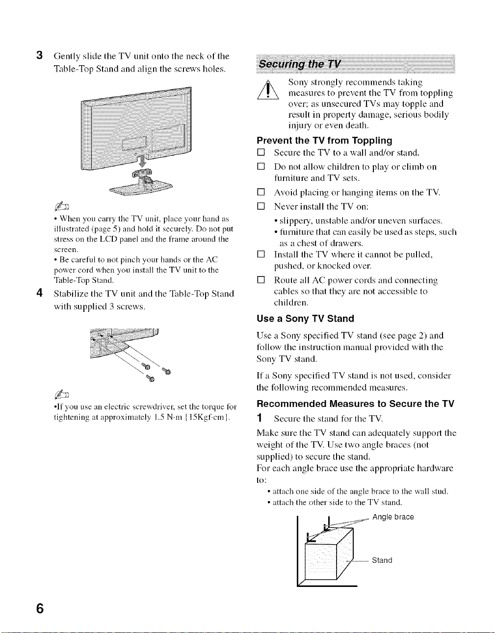
Gently slide the TV unit onto the neck of the
Table-Top Stand and align the screws holes.
• When you carry the TV unit, place your hand as
illustrated (page 5) and hold it securely. Do not put
stress on the LCD panel and the frame around the
screen.
• Be careful to not pinch your hands or the AC
power cord when you install the TV unit to the
Table-Top Stand.
Stabilize the TV unit and the Table-Top Stand
with supplied 3 screws.
%
•If you use an electric screwdriver, set the torque for
tightening at approximately 1.5 N.m {15Kgf.cm }.
Sony strongly recommends taking
measures to prevent the TV from toppling
over; as unsecured TVs may topple and
result in property damage, serious bodily
injury or even death.
Prevent the TV from Toppling
[] Secure the TV to a wall and/or stand.
[] Do not allow children to play or climb on
furniture and TV sets.
[] Avoid placing or hanging items on the TV.
[] Never install the TV on:
• slippery, unstable and/or uneven surfaces.
• furniture that can easily be used as steps, such
as a chest of drawers.
[] Install the TV where it cannot be pulled,
pushed, or knocked over.
[] Route all AC power cords and connecting
cables so that they are not accessible to
children.
Use a Sony TV Stand
Use a Sony specified TV stand (see page 2) and
follow the instruction manual provided with the
Sony TV stand.
If a Sony specified TV stand is not used, consider
the following recommended measures.
Recommended Measures to Secure the TV
1 Secure the stand for the TV.
Make sure the TV stand can adequately support the
weight of the TV. Use two angle braces (not
supplied) to secure the stand.
For each angle brace use the appropriate hardware
to:
• attach one side of the angle brace to the wall stud.
• attach the other side to the TV stand.
_ ngle brace
Stand
6

2 Secure the TV to the stand.
Use the optional hardware listed below (not
supplied):
• M6 x 12-18 mm anchor bolt (screwed into the
TV's Table-Top stand)
• A screw or similar (attach it to the TV stand)
• Rope or chain (strong enough to support the
weight of the TV). Make sure that there is no
excess slack in the rope or chain.
An alternative way to secure the TV is with an
optional Sony Support Belt Kit.
Screw hole on
the Table-Top
stand
Contact Sony Customer Support to obtain the optional
Support Belt Kit by providing your TV model name.
• For United States call: 1-800-488-7669 or visit:
www.sony.com/accessories
• For Canada call: 1-877-899-7669
3 Anchor the TV to the Wall.
Wall-
_'°'--anchor
• Measure 2 provides minimal protection against the TV
toppling over. For further protection, )\>llow all three
measures recomn]ended above.
Use the hardware listed below (not supplied):
• Two M6 x 12-18 mm anchor bolts (screw into
the top-most wall-mount holes located on the
rear of the TV)
• Rope or chain (attach to one M6 anchor bolt)
• W_dl-anchor (attach to the wall stud) strong
enough to support the weight of the TV (pass
the rope through the wall-anchor, then attach to
the other M6 anchor bolt).
Anchor bolts
......................... Rope or
WalFmoun chain
holes
(Continued)
7
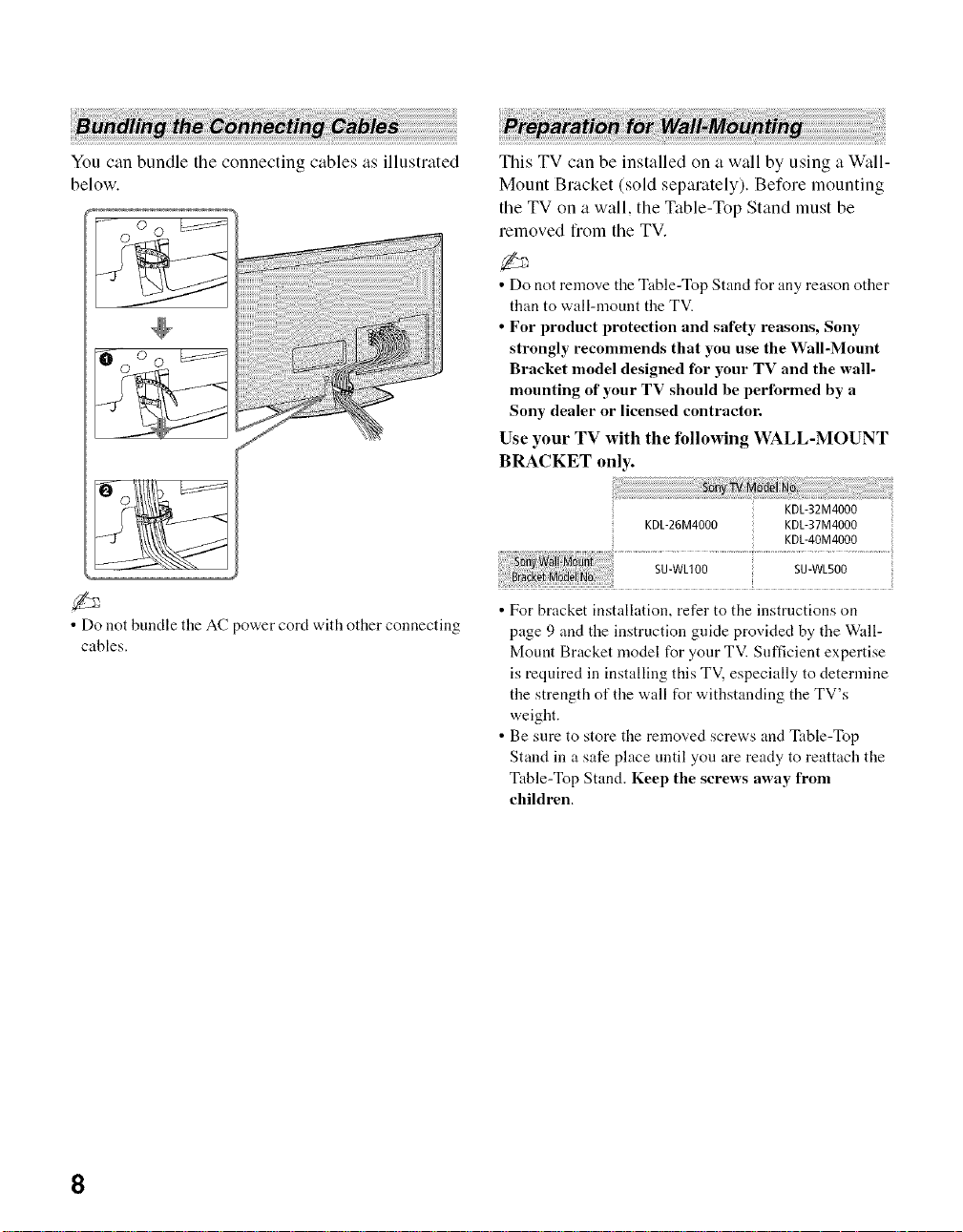
You can bundle the connecting cables as illustrated
below,
This TV can be installed on a wall by using a Wall-
Mount Bracket (sold sepalately). Before mounting
the TV on a wall, the Table-Top Stand must be
removed fiom the TV.
• Do not remove the Table-Top Stand for any reason other
than to wall-mount the TV.
• For product protection and safety reasons, Sony
strongly recommends that you use the Wall-Mount
Bracket model designed for your TV and the wall-
mounting of your TV should be performed by a
Sony dealer or licensed contractor.
Use your TV with the following WALL-MOUNT
BRACKET only.
• Do not bundle the AC power cord with other connecting
cables.
KDL-26M4000 KDL-37M4000
SU-WLIO0 SU-WL500
• For bracket installation, refer to the instructions on
page 9 and the instruction guide provided by the Wall-
Mount Bracket model for your TV. Sufficient expertise
is required in installing this TV. especially to determine
the strength of the wall for withstanding the TV's
weight.
• Be sure to store the removed screws and Table-Top
Stand in a safe place until you are ready to reattach the
Table-Top Stand. Keep the screws away from
children.
KDL-32M4000
KDL-4OM4000
8

Follow the simple steps below to remove the Table-
Top Stand:
1 Disconnect all the cables fiom the TV.
2 Remove the 3 screws fiom behind the TV as
indicated below. Do not remove any other
screws from the TV.
3 Gently lay the TV (face down) onto a level and
stable surface covered with a thick and soft
cloth.
4 Secure the Mounting Hooks to the rear of the
TV. For more details refer to Install the Wall-
Mount Bracket and also the Instruction
Guide provided by the Wall-Mount Bracket
model for your TV.
• If an electric screwdriver is used, set the torque to
tighten at approximately 1.5 N'm {15Kgf'em}.
To Customers
Your KDL-26M4000/KDL-32M4000/
KDL-37M4000/KDL-40M4000 can be _"
wall-mounted using a Wall-Mount Bracket (sold t_
separately). See table on page 8 showing the Wall-
Mount Bracket model appropriate for your TV.
For product protection and safety, Sony strongly
recommends that you use the Wall-Mount
Bracket designed for your TV and wall-
mounting is performed by a Sony dealer or a
licensed contractor. Do not attempt to install it
yourself. Sony is not liable for any damage or
injury caused by mishandling or improper
installation.
Please provide this installation information as well
as the instruction supplied in the Wall-Mount
Bracket package to your installer
To Sony Dealers and Licensed Contractors
To avoid injury and property damage, read these
instructions carefully. Periodic inspection and
maintenance is highly recommended to ensure that
TV is securely mounted.
Installing the Wall-Mount Bracket and
Mounting Hooks
1 Open the Wall-Mount Bracket package and
check for all the required parts including the
instruction.
2 See Installation dimensions table to determine
the best location for wall-mounting. The wall
must be strong enough to support at least four
times the weight of the TV. Also refer to the
instruction provided with your Wall-Mount
Bracket.
(Continued)
9
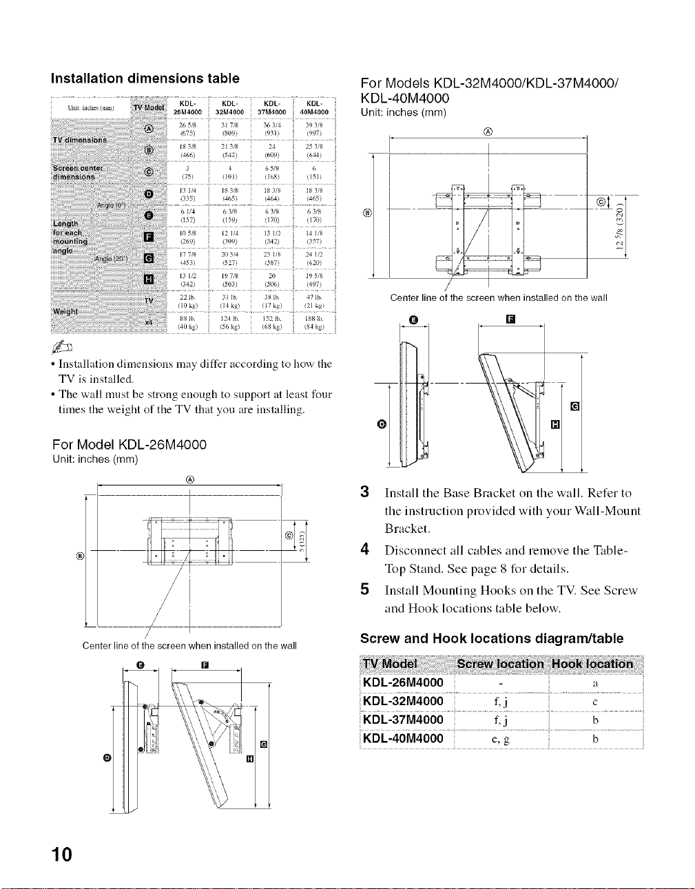
Installation dimensions table
• Installation dimensions may differ according to how the
TV is installed.
• The wall nmst be strong enough to support at least four
times the weight of the TV that you are installing.
For Model KDL-26M4000
unit: inches (ram)
®
For Models KDL-32M4000/KDL-37M4000/
KDL-4OM4000
unit: inches (mm)
@
I
Center line of the screen when installed on the wall
[]
3 Install the Base Bracket on the wall. Refer to
the instruction provided with your W_fll-Mount
Bracket.
4 Disconnect all cables and remove the Table-
Top Stand. See page 8 for details.
5 Install Mounting Hooks on the TV. See Screw
and Hook locations table below.
Center line of the screen when installed on the wall
/
10
Screw and Hook locations diagram/table
KDL-26M4000 a
KDL-32M4000 f.j c
',KDL-37M4000 f, j b
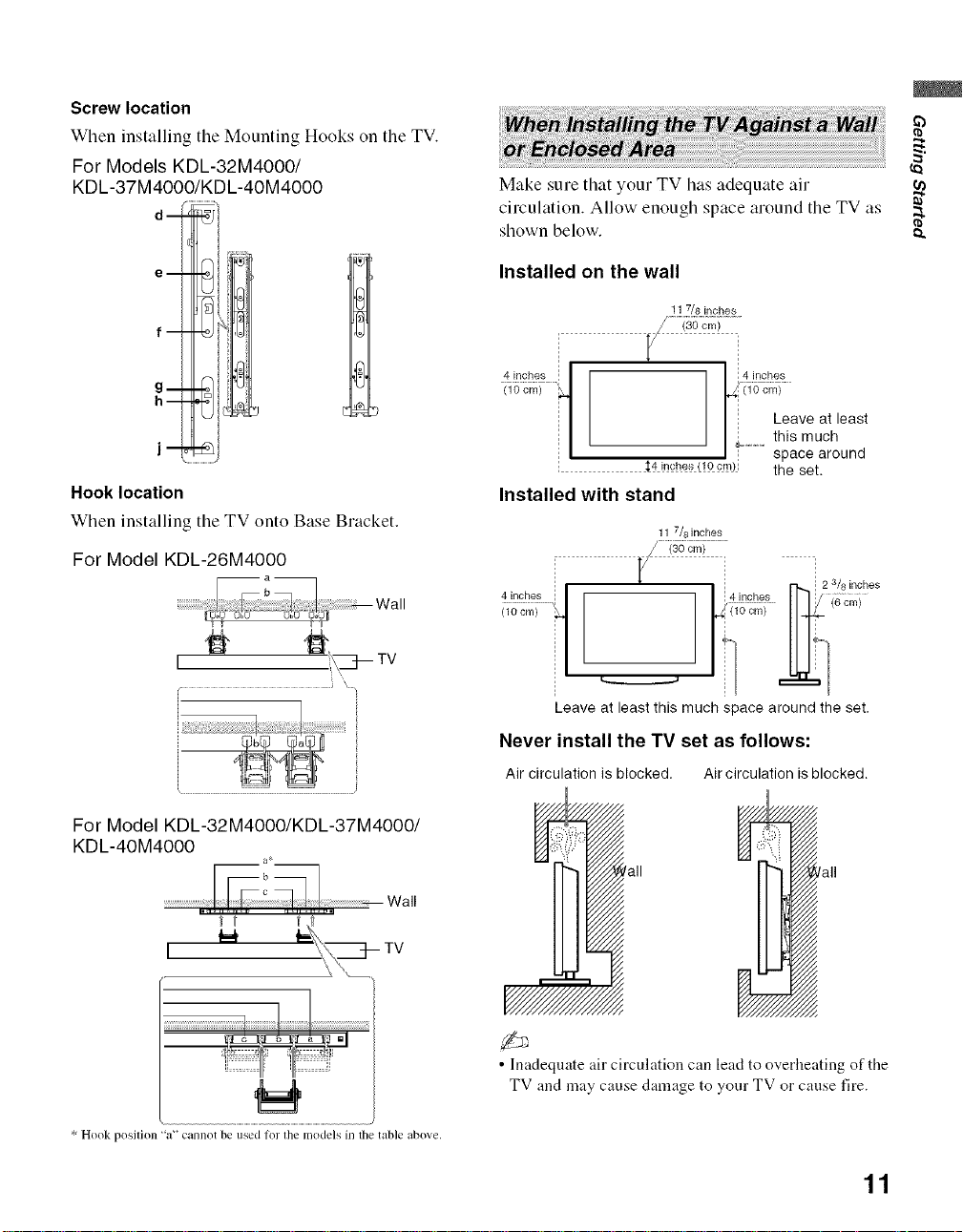
Screw location
When installing the Mounting Hooks on the TV.
For Models KDL-32M4000/
KDL-37M4000/KDL-40M4000
d-
Make sure that your TV has adequate air
circulation. Allow enough space around tile TV as
shown below.
e- !
D
f--
h--
Hook location
When installing tile TV onto Base Bracket.
For Model KDL-26M4000
1#
...............................!_7__ ..................)
For Model KDL-32M4000/KDL-37M4000/
KDL-4OM4000
a*
Installed on the wall
11 7/8 inches
4 inches ! ! 4 inches
0; c,Y,>....... i_c_,_........
1 1
_ Leaveat least
I_ ............this much
i _4i_ches(!Ocm)i the set.
Installed with stand
11 7/8 inches
_ space around
V
4ilches i ! !r)£!_ II 17 {6cmi
{ic;_i....... _0ore> 1144-
1 i ,,,
Leave at least this much space around the set.
Never install the TV set as follows:
Air circulation is blocked. Air circulation is blocked.
fall
t _
I
* Hook position "a'" cannot be used for the models in tile table above.
• Inadequate air circulation can lead to overheating of the
TV and may cause damage to your TV or cause fire.
11

2. Locating Inputs and Outputs
WDEO_N'
[] VIDEO IN 2 Connects to the composite video and audio output jacks on your camcorder or other video
VIDEO/ equipment such as a DVD or video game equipment.
L (MONO) - f-2_-_)
AUDIO- R • If you have mono equipment, connect its audio output jack to the TV's L (MONO) audio
input jack.
[] Headphone Connects to your headphones. If your headphones do not match the jack, use a suitable plug
jack adapter (not supplied).
12
• While headphones are connected, the TV speakers are muted.
ANTENNA
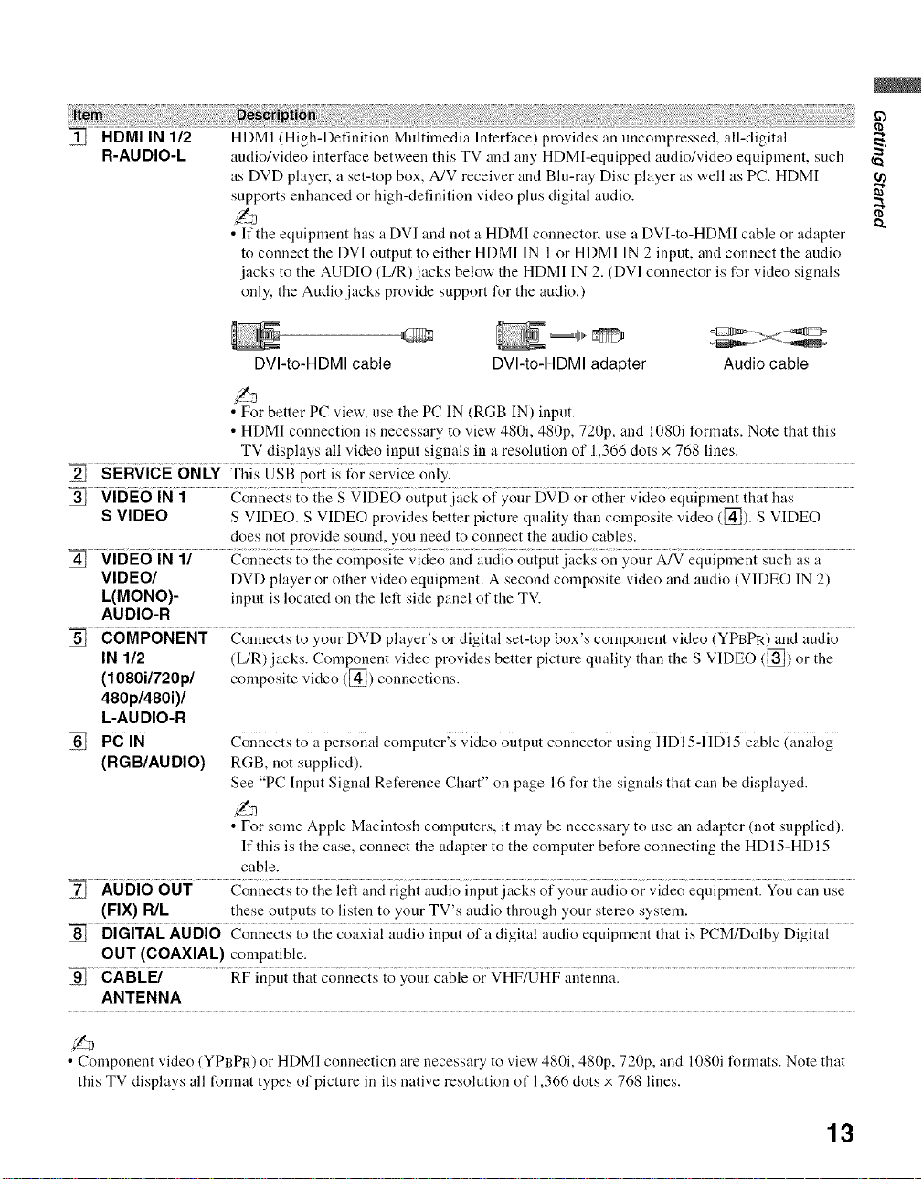
[] HDMI IN 1/2 HDMI (High-Definition Multiinedia Interface) provides an uncompressed, all-digital
R-AUDIO-L audio/video interface between this TV and any HDMI-eqnipped audio/video equipiuent, such _
as DVD player, a set-top box, A/V receiver and Bhi-ray Disc player as well as PC. HDMI
supports enhanced or high-definition video plus digital audio.
• If the equipment has a DVI and not a HDMI coimector, use a DVI-to-HDMI cable or adapter
to connect the DVI output to either HDMI IN 1 or HDMI IN 2 input, and connect the audio
jacks to the AUDIO (L/R) jacks below the HDMI IN 2. (DVI connector is for vkteo signals
only, the Audio jacks provide support for the audio.)
DVI-to-HDMI cable DVI-to-HDMI adapter Audio cable
• For better PC view, use the PC IN (RGB IN) input.
• HDMI connection is necessary to view 480i, 480p, 720p, and 1080i formats. Note that this
TV displays all video input signals in a resolution of 1,366 dots x 768 lines.
[] sERvicE 6NLY Tiiis WgB pori is for service oniyl....
S VIDEO S VIDEO. S VIDEO provides better pictnre quality thai] composite video ([_). S VIDEO
does not provide sonnd, you need to connect the andio cables.
[] VIDE6iN1/ Connecisio{hgZoZpo_i_g_;i_iZoa;_iaii_iioouipuii.ck_ouyoub_N Ziuipzeni_{iZh,i_a
VIDEO/ DVD player or other vkteo equipment. A second composite video and audio (VIDEO IN 2)
L(MONO)- input is located on the left side panel of the TV.
AUDIO-R
[] COMPONENT Connects to yonr DVD player's or digital set-top box's component video (YPBPR) and audio
IN 1/2 (L/R) jacks. Coinponent video provides better picture quality than the S VIDEO ([]) or the
(1080i/720p/ coinposite video ([_) connections.
480p/480i)/
L-AUDIO-R
[] PciN
(RGB/AUDIO) RGB, not supplied).
See "PC Input Signal Reference Chart" on page 16 for the signals that can be displayed.
• For some Apple Macintosh computers, it may be necessary to use an adapter (not supplied).
If this is the case, connect the adapter to the coinpnter before connecting the HD 15-HDI 5
cable.
[] AUDi6 6UT Coi_necisio iiieieft ",,ndrighi auciioiupui iacksof your auciioor ;,ideoeq{iipil_enilYou can use
(FIX) NIL these outputs to listen to your TV's audio through your stereo systein.
[] DiGiTAL AUDio Connec{s {o {he co_xiai iiudio inpu{ of i{digi{ai audio equipi{{en{{i_a{is }CM2Doigy Digi{al
OUT (COAXIAL) coinpatible.
eaBc .................R>inpd{{t,_,i_onnzi_{oygu gggieor _HF2_HP "{ gnna:..............................................................................................................
ANTENNA
• Component video (YPBPR) or HDMI connection are necessary to view 480i, 480p, 720p, and 1080i l\mnats. Note that
this TV displays all format types of picture in its native resolution of 1,366 clots x 768 lines.
13
3. Connecting the TV
Cable or VHF/UHF (or VHF only)
75-ohm coaxialcable
(not supplied) _ _ Rear of TV
CABLE/ANTENNA input
• It is strongly recommended that you connect the antenna/cable input using a 75-ohm coaxial cable (not supplied) to
receive optimmn picture quality. A 300-ohm twin lead cable can be easily affected by radio frequency interference,
resulting in signal degradation.
Cable and VHF/UHF (or VHF only)
If you want to watch both cable and antenna (over-the-air) programming, you will need to use an optional A-
B RF Switch (not supplied) to switch between the cable and over-the-air antenna programming, as shown.
A-B RF
Switch
• Be sure to set Cable setting to On or Off in Channel menu for the type of input signal you choose (see page 33 for
more details).
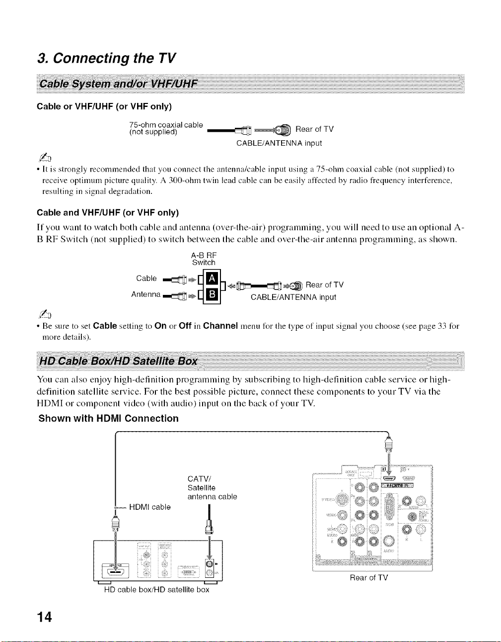
You can also enjoy high-definition programming by subscribing to high-definition cable service or high-
definition satellite service. For the best possible picture, connect these components to your TV via the
HDMI or component video (with audio) input on the back of your TV.
Shown with HDMI Connection
CATV/
Satellite
antenna cable
HDMI cable
Rear of TV
HD cable box/HD satellite box
t-..-a
14
 Loading...