

Page 1
A-DAD-100-13(1)
Additional Information for
Using Sony Wall-Mount Bracket (SU-WL500)
Compatible TV models for this Wall-Mount Bracket information:
KDL-32LL150
KDL-32L5000
KDL-32L504
KDL-37L5000
For product protection and safety reasons, Sony strongly recommends that you use the
Wall-Mount Bracket model designed for your TV and that the wall-mounting of your TV
is performed by Sony dealers or licensed contractors.
To Customers
Please provide your licensed contractor with this installation supplement as well as the instructions
(supplied with the SU-WL500 Wall-Mount Bracket). Read these documents carefully for safety and proper
installation.
To Sony Dealers and Contractors
Provide full attention to safety during the installation, periodic maintenance and examination of this
product.
Sufficient expertise is required in installing this product, especially to determine the strength
of the wall for withstanding the TV’s weight. Be sure to entrust the attachment of this product
to the wall to Sony dealers or licensed contractors and pay adequate attention to safety during
the installation. Sony is not liable for any damage or injury caused by mishandling or improper
installation.
For proper installation, follow your wall-mount bracket instructions and the directions below.
Additional Information for Using Sony Wall-Mount Bracket (SU-WL500)
− 1 −
Page 2
Step 1: Checking the parts required for the installation
Open the Wall-Mount Bracket package and check the contents for all required parts along with the
Instructions.
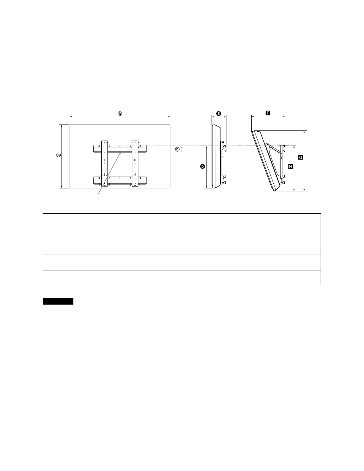
Step 2: Deciding on the installation location
Decide where you want to install your TV. Refer to the TV installation dimensions table.
Refer to the Instructions for SU-WL500.
Dimension Table
Screen center point
Unit: inches (mm)
Model Name
KDL-32LL150
KDL-32L5000/
KDL-32L504
KDL-37L5000
Display
dimensions
31 5/8
(801)
31 7/8
(807)
36 1/2
(927)
19 7/8
(505)
20
(508)
22 5/8
(574)
Screen center
dimensions
6 7/8
(172)
6 7/8
(172)
5 5/8
(140)
Length for each mounting angle
Angle (0°) Angle (20°)
17
(429)
17
(430)
17 1/8
(432)
6 1/8
(154)
6 1/8
(154)
6 1/4
(156)
12
(303)
11 7/8
(300)
12 7/8
(324)
19 1/4
(487)
19 1/8
(485)
21 3/8
(542)
18 1/2
(468)
18 3/8
(466)
18 1/2
(468)
Figures in the above table may dier slightly depending on the installation.
CAUTION
e wall that the TV will be installed on should be capable of supporting a weight of at least four times that of the TV.
Refer to your TV’s operating instructions for its weight.
Step 3: Installing the Base Bracket on the wall
Refer to the Instructions for SU-WL500.
Additional Information for Using Sony Wall-Mount Bracket (SU-WL500)
− 2 −
Page 3

Step 4: Preparing the TV for wall mount installation
h
j
g
f
e
d
h
j
g
f
e
d
h
j
g
f
e
d
a*
b
c
Follow the steps below to prepare for installing the TV.
1 Disconnect all the cables from the TV.
2 Secure the Mounting Hook to the rear of the TV.
Determine the screw locations and secure the Mounting Hooks to the rear of the TV. Refer to
the “Screw and Hook Locations Diagram/Table” shown below.
Secure the Mounting Hooks to the rear of the TV using only the supplied screws
(+PSW6 × 16).
Be sure to tighten the screws with equal torque strength.
Square
hole
Align the tab on the
rear of the Mounting
Hook with the square
hole on the rear of the
TV as illustrated.
Mounting Hook
Screw
(+PSW
6 × 16)
Square
hole
Tab
Screw and Hook Locations Diagram/Table
Model Name Screw Locations Hook Location
KDL-32LL150/KDL-32L5000/KDL-32L504 e, g c
KDL-37L5000 d, g b
Screw Location
When installing the Mounting Hook on the TV.
Hook Location
When installing the TV onto the Base Bracket.
* Hook position “a” cannot be used for the
models in the table above.
Additional Information for Using Sony Wall-Mount Bracket (SU-WL500)
− 3 −
Page 4

3 Adjust the angle of the Mounting Hook using the hexagon wrench supplied
with the Wall-Mount Bracket.
When installing the TV parallel to the wall (0 degrees), adjustment of the Mounting Hook angle
(procedures and below) is not necessary. Make sure that each arm base X is screwed in securely.
Remove the two screws from the arm base X of the Mounting Hook. Choose the holes
corresponding to the desired angle (5, 10, 15 or 20 degrees).
Adjust the angles of the top Y and bottom Z arm to t the corresponding hole, and rmly
secure each arm using the two screws removed in the previous procedure .
Hexagon
wrench
✍
• Be sure to adjust the right and le arms to the same angle.
• Make sure that the two arm bases are screwed in securely.
CAUTION
Be careful not to pinch your ngers when adjusting the angle of the Mounting Hook.
4 Remove the screws from the back of the TV.
Do not remove any other screws from the TV.
5 Lift the TV o the stand. Make sure that you carry out this task with at least two
or three people.
Do not attempt to li the TV by yourself.
Step 5: Installing the TV on the wall
Refer to the Instructions for SU-WL500.
✍
• When you put the TV back on the stand, reverse the above steps.
• When moving the TV, do not squeeze the bottom of the front panel too strongly.
• Remove the screws or install the Mounting Hook on a stable and level surface.
Additional Information for Using Sony Wall-Mount Bracket (SU-WL500)
− 4 −
 Loading...