

SONY KDL-32V2000, KDL-40V2000, KDL-46V2000 Service Manual

WAX2
RM-ED005
SERVICE MANUAL
MODEL
KDL-32V2000
KDL-40V2000
KDL-46V2000
COMMANDER DEST
RM-ED005 AEP
RM-ED005 AEP
RM-ED005 AEP
WAX2
MODEL
KDL-32V2000
KDL-40V2000
KDL-46V2000
COMMANDER DEST
CHASSIS
RM-ED005 UK
RM-ED005 UK
RM-ED005 UK
KDL-32V2000 / KDL-40V2000 / KDL-46V2000
FLAT PANEL COLOR TV
- 1 -
RM-ED005

WAX2
RM-ED005
TABLE OF CONTENTS
Section Title Pag e Section Title Pa ge
Caution ................................................................ 3
Specifications ...................................................... 4
Connectors .......................................................... 6
Self Diagnosis ..................................................... 7
3-5. Panel Replacement ............................................. 29
3-6. Board Replacement ............................................ 29
3-6-1. AE Board Replacement ................................... 29
3-6-2. BE Board Replacement .................................... 29
1. GENERAL ................................................................... 8
2. DISASSEMBLY
2-1. Rear Cover Removal ........................................... 18
2-2. Stand Removal .................................................... 18
2-3. Vesa Bracket Removal ........................................ 19
2-4. Shield Cover Removal ........................................ 19
2-5. Speaker Removal ................................................ 20
2-6. AC Inlet Removal ............................................... 20
2-7. AE and TUE Board Removal ............................. 21
2-8. BE and FEE Board Removal .............................. 21
2-9. G1 or G2 Board Removal................................... 22
2-10. H1E Board Removal ........................................... 22
2-11. H2E or H46E Board Removal ............................ 23
2-12. H4E Board Removal ........................................... 23
2-13. Shield Base Removal .......................................... 24
2-14. LCD Panel Removal ........................................... 24
3. SET-UP ADJUSTMENTS
3-1. How to enter Service Mode ............................... 25
3-2. Signal Level Adjustment .................................... 25
3-2-1. Set up of AD calibration1 adjustment for
terrestrial analog ............................................... 25
3-2-2. Y signal calibration1 adjustment for
terrestrial analog ............................................... 25
3-2-3. Set up of C signal calibration1 adjustment for
terrestrial analog ............................................... 25
3-2-4. C signal calibration1 adjustment for
terrestrial analog ............................................... 26
3-2-5. Set up of AD calibration1 adjustment for
video ................................................................ 26
3-2-6. Y signal calibration1 adjustment for video ...... 26
3-2-7. Set up of C signal calibration1 adjustment for
video ................................................................ 26
3-2-8. C signal calibration1 adjustment for video ...... 26
3-2-9. Set up of AD calibration2 adjustment for
video ................................................................ 26
3-2-10. Y signal calibration2 adjustment for video .... 26
3-2-11. Set up of C signal calibration2 adjustment for
video .............................................................. 27
3-2-12. C signal calibration2 adjustment for video .... 27
3-3. Gamma Adjustment ........................................... 27
3-3-1. Set up mode for Gamma Adjustment .............. 27
3-3-2. Set up Trident internal SG and brightness
measurement .................................................... 27
3-4. White Balance Adjustment ................................. 27
3-4-1. Set up mode for White Balance Adjustment ... 27
3-4-2. White Balance of colour temperature “High” .. 27
4. DIAGRAMS
4-1. Block Diagrams(1) ............................................. 30
Block Diagrams(2) ............................................. 31
Block Diagrams(3) ............................................. 32
Block Diagrams(4) ............................................. 33
4-2. Circuit Board Location ........................................ 33
4-3. Schematic Diagrams and Printed Wiring
Boards ................................................................. 33
AE Board Schematic Diagram ............................ 34
AE Printed Wiring Board ................................. 38
BE Board Schematic Diagram ............................ 40
BE Printed Wiring Board ................................... 50
FEE Board Schematic Diagram .......................... 52
FEE Printed Wiring Board ................................. 58
G2 Board Schematic Diagram
(KDL-40V2000, KDL-46V2000) ...................... 59
G2 Printed Wiring Board
(KDL-40V2000, KDL-46V2000) ................... 60
H1E Board Schematic Diagram .......................... 62
H1E Printed Wiring Board ............................... 63
H2E Board Schematic Diagram .......................... 62
H2E Printed Wiring Board ............................... 63
H4E Board Schematic Diagram .......................... 62
H4E Printed Wiring Board ............................... 63
H46E Board Schematic Diagram
(KDL-46V2000) ................................................. 64
H46E Printed Wiring Board
(KDL-46V2000) ................................................. 63
TUE Schematic Diagram .................................... 64
TUE Printed Wiring Board ............................... 66
4-4. Semiconductors .................................................. 67
5. EXPLODED VIEWS
5-1. Chassis................................................................ 69
5-2. Rear Cover, Stand and Vesa Bracket .................. 70
6. ELECTRICAL PARTS LIST .................................. 71
WARNING !!
AN ISOLATION TRANSFORMER SHOULD BE USED DURING
ANY SERVICE WORK TO AVOID POSSIBLE SHOCK HAZARD
DUE TO LIVE CHASSIS, THE CHASSIS OF THIS RECEIVER IS
DIRECTLY CONNECTED TO THE POWER LINE.
SAFETY-RELATED COMPONENT WARNING !!
COMPONENTS IDENTIFIED BY SHADING AND MARKED
THE SCHEMATIC DIAGRAMS, EXPLODED VIEWS AND IN THE
PARTS LIST ARE CRITICAL FOR SAFE OPERATION. REPLACE
THESE COMPONENTS WITH SONY PARTS WHOSE PART
NUMBERS APPEAR AS SHOWN IN THIS MANUAL OR IN
SUPPLEMENTS PUBLISHED BY SONY.
ON
- 2 -
CAUTION
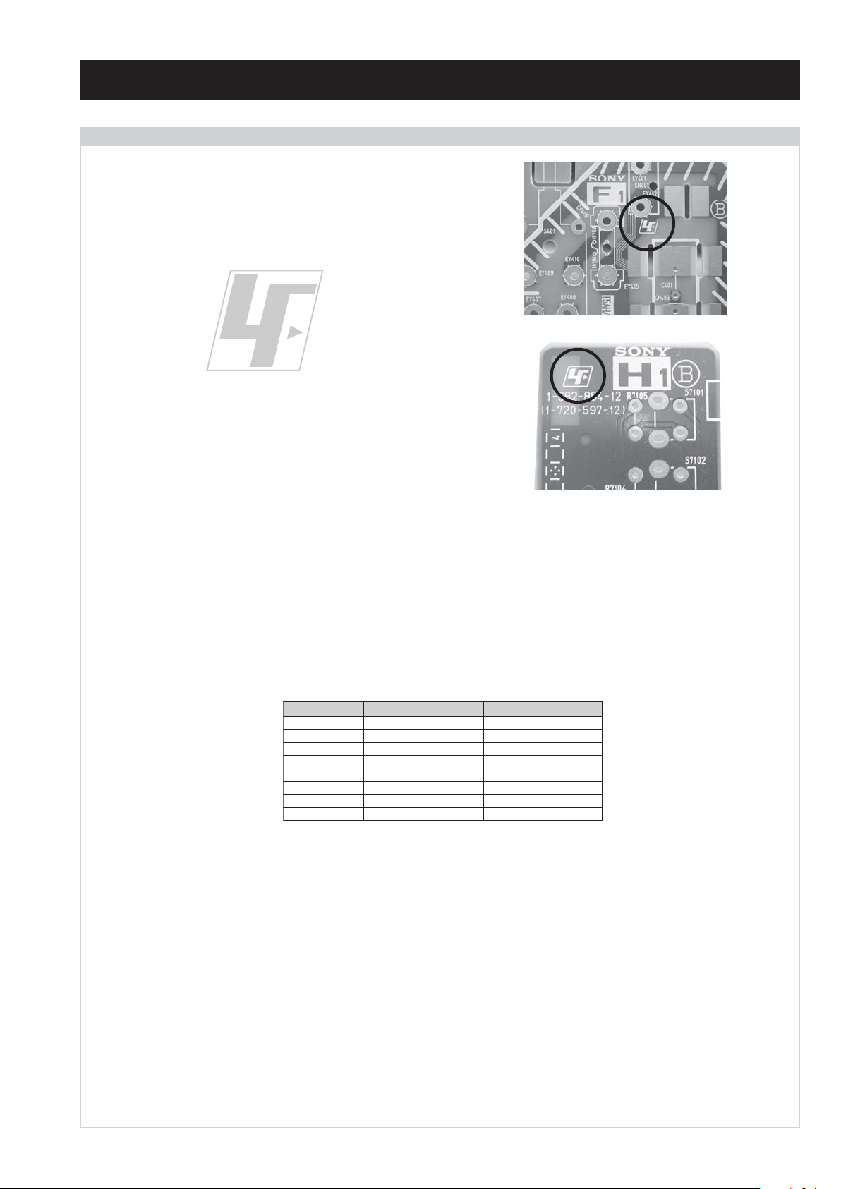
Lead Free Soldered Boards
The circuit boards used in these models have been processed using
Lead Free Solder. The boards are identified by the LF logo located
close to the board designation e.g. F1, H1 etc [ see examples ]. The
servicing of these boards requires special precautions to be taken as
outlined below.
WAX2
RM-ED005
example 1
example 2
It is strongly recommended to use Lead Free Solder material in order to guarantee optimal quality of new solder joints. Lead Free Solder is
available under the following part numbers :
rebmuntraP retemaiD skrameR
91-500-046-7mm3.0gK52.0
02-500-046-7mm4.0gK05.0
12-500-046-7mm5.0gK05.0
22-500-046-7mm6.0gK52.0
32-500-046-7mm8.0gK00.1
42-500-046-7mm0.1gK00.1
52-500-046-7mm2.1gK00.1
62-500-046-7mm6.1gK00.1
Due to the higher melting point of Lead Free Solder the soldering iron tip temperature needs to be set to 370 degrees centigrade. This requires
soldering equipment capable of accurate temperature control coupled with a good heat recovery characteristics.
For more information on the use of Lead Free Solder, please refer to http://www.sony-training.com
- 3 -
WAX2
RM-ED005
NOTE
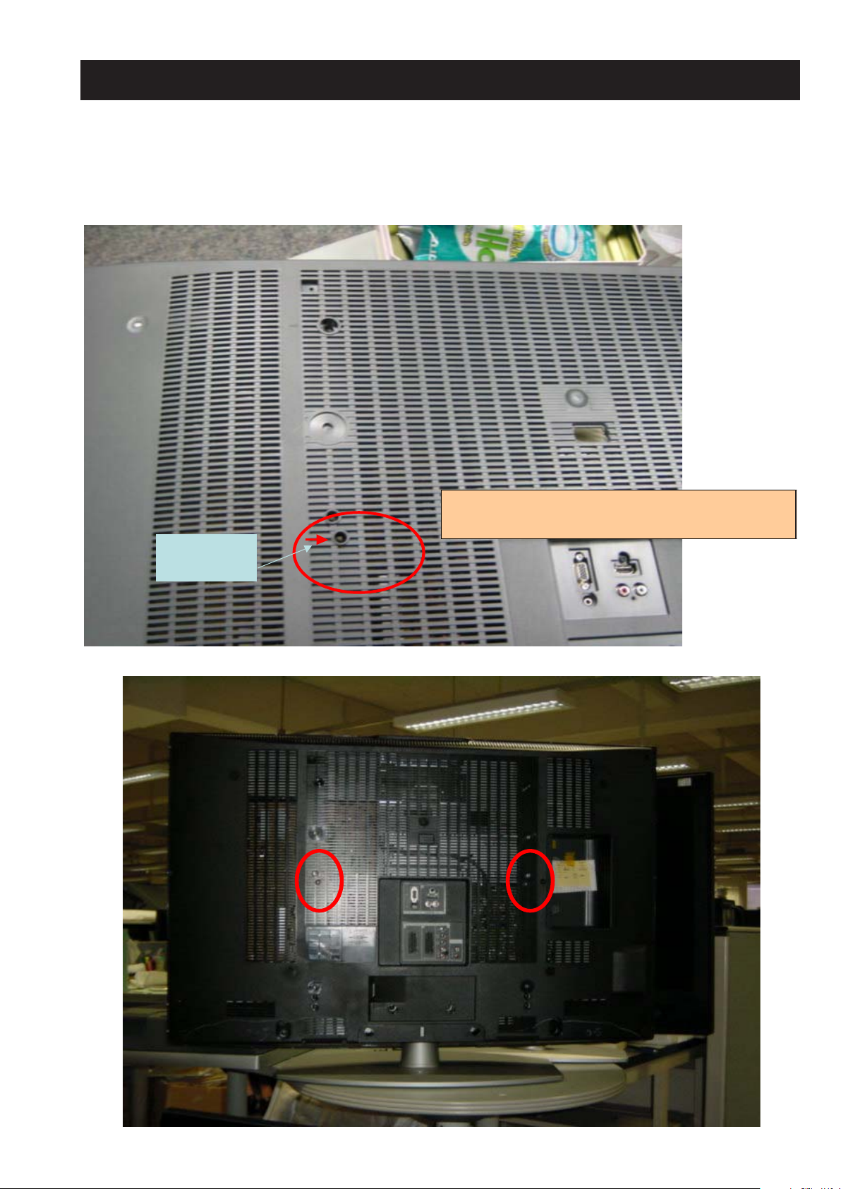
The photographs below are of a WAX2 rear cover. However, for models KDL-32V2000, KDL-40V2000
and KDL-46V2000 a screw will be added on both the left and righthand side of the rear cover to improve
sound quality.
New arrow
position
Existing hole 40WAX2.
For basic model no screw will be fitted.
For step up model sc rew will be added for sound quality
LEDOMMETI metsySnoisiveleT metsySoeretS egarevoClennahC metsySroloC
ET-BVD,L,I,K/D,H/G/B
UT-BVD,IoeretSM
ACIN96B-12B:FHU
MACIN/NAMREG
oeretS
21E-20E:FHV
96E-12E:FHU
02S-10S:VTAC
14S-12S:REPYH
R,21R-1R:K/D
96R-12
96B-12BFHU:I
96F-12F,Q-B,01F-2F:L
WAX2
RM-ED005
MACES,LAP
34.4/85.3CSTN
)YLNOOEDIV(
LM@PM2-GEPM
MACES,LAP
34.4/85.3CSTN
)YLNOOEDIV(
LM@PM2-GEPM
LCD(Liquid Crystal Display) Panel
Projected Picture Size
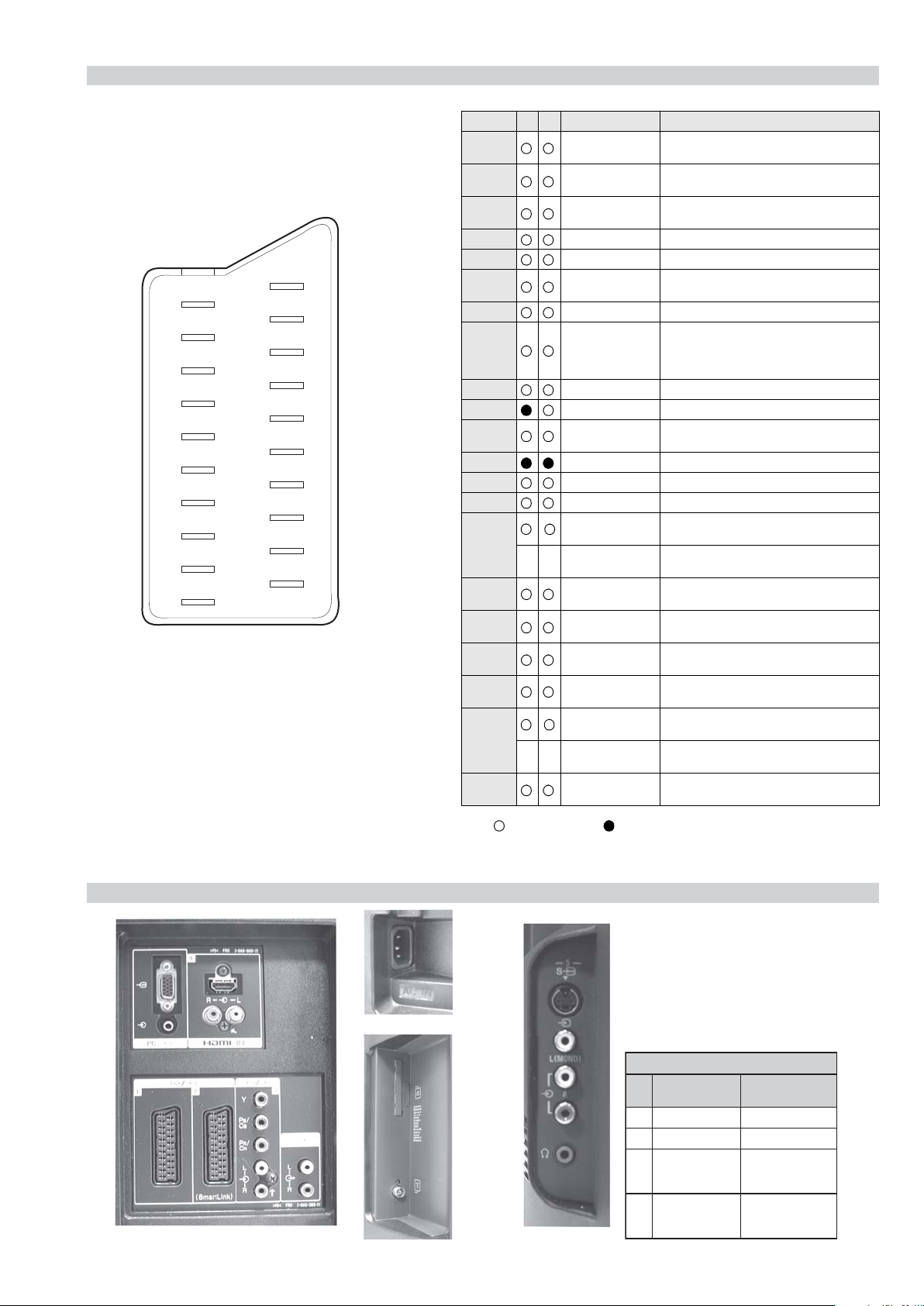
Input/Output Terminals [REAR] General Specifications
1: 21-pin Euro connector
(CENELEC standard)
2: 21-pin Euro connector
(CENELEC standard)
Approx 80.1cm (KDL-32V2000)
Approx 101.6cm (KDL-40V2000)
Approx 116.9cm (KDL-46V2000).
Inputs for Audio and Video signals.
Inputs for RGB.
Outputs of TV Video and Audio
signals.
Inputs for Audio and Video signals.
Inputs for RGB.
Outputs of Video and Audio signals
(Selectable). SmartLink interface.
Sound Output
Right and Left speaker
Sub-woofer
Power Requirements 220 - 240V
Power Consumption/
Standby
Dimensions
Weight
2 x 10W (RMS)
Approx 145W/0.3W (KDL-32V2000)
Approx 180W/0.3W (KDL-40V2000)
Approx 250W/0.3W (KDL-46V2000)
Approx 792x593x219mm
(KDL-32V2000 with stand)
Approx 792x546x99mm
(KDL-32V2000 without stand)
Approx 988x716x334mm
(KDL-40V2000 with stand)
Approx 988x664x103mm
(KDL-40V2000 without stand)
Approx 1120x805x334mm
(KDL-46V2000 with stand)
Approx 1120x755x116mm
(KDL-46V2000 without stand)
Approx 17kg (KDL-32V2000 with stand)
Approx 15kg (KDL-32V2000 without stand)
Approx 27kg (KDL-40V2000 with stand)
Approx 21kg (KDL-40V2000 without stand)
Approx 34kg (KDL-46V2000 with stand)
Approx 28kg (KDL-46V2000 without stand)
RM-ED005 Remote Commander (1)
Phono Jacks
HDMI Input HDMI Connector.
PC Input 15 Pin D-Sub Connector.
CAM Conditional Access Module
Input/Output Terminals [SIDE] Remote control system : Infrared control
Headphone jack Stereo mini jack
Audio input Phono jacks
Video input Phono jack
S Video input 4 pin mini DIN
Output Connectors variable for
Audio Signals.
Design and specifications are subject to change without notice.
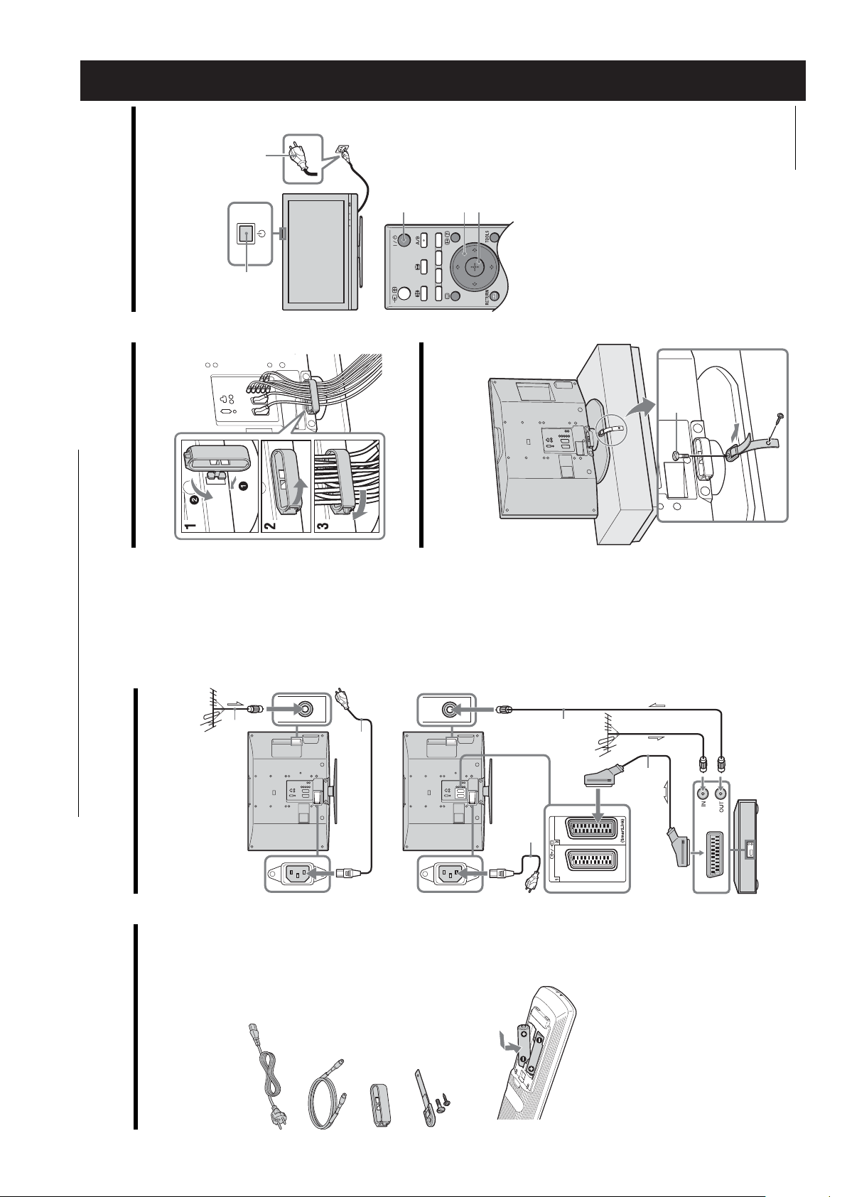
Supplied Accessories
Other Features
Power requirements
IEC designated R06 battery (2)
Mains Lead (1)
RF Lead (1)
Cable Holder
Support Belt and Screws
Wide viewing angle LCD Panel, DVB-T Tuner,
Live colour creation, Highly integrated systemon-a-chip (Trident), HDMI input, PC input.
3V dc
2 batteries IEC designation
R06 (size AA)
- 4 -
WAX2
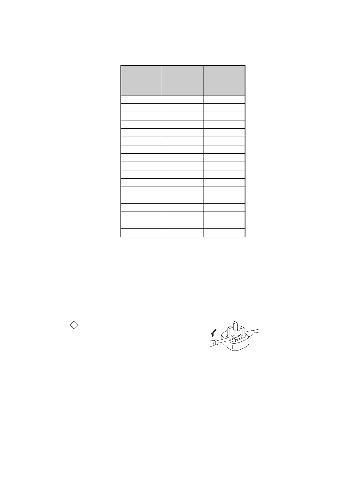
How to replace the fuse.
Open the fuse compartment with
a screwdriver blade and replace
the fuse.
FUSE
RM-ED005
Model Name
Item
PA P OF F O F F
PAT O F F O F F
RGB Priority ON ON
Sub Woofer OFF OFF
Scart 1 ON ON
Scart 2 ON ON
Front in (5) ON ON
Projector OFF OFF
Norm B/G ON OFF
Norm I ON ON
Norm D/K ON OFF
Norm AUS OFF OFF
Norm L ON OFF
Norm SAT OFF OFF
Norm M OFF OFF
Teletext ON ON
Nicam Stereo ON ON
KDL-32V2000E
KDL-40V2000E
KDL-46V2000E
KDL-32V2000U
KDL-40V2000U
KDL-46V2000U
WARNING (UK Models only)
The flexible mains lead is supplied connected to a B.S. 1363 fused
plug having a fuse of 13 AMP rating. Should the fuse need to be
replaced, use a 13AMP FUSE approved by ASTA to BS 1362, ie one
that carries the
IF THE PLUG SUPPLIED WITH THIS APPLIANCE IS NOT SUITABLE FOR THE OUTLET SOCKETS IN YOUR HOME, IT SHOULD
BE CUT OFF AND AN APPROPRIATE PLUG FITTED. THE PLUG
SEVERED FROM THE MAINS LEAD MUST BE DESTROYED AS A
PLUG WITH BARED WIRES IS DANGEROUS IF ENGAGED IN A
LIVE SOCKET.
When an alternative type of plug is used, it should be fitted with a
13 AMP FUSE, otherwise the circuit should be protected by a
13AMP FUSE at the distribution board.
ASA
T
mark.
- 5 -
21 pin connector
21
19
17
15
13
11
9
7
5
3
1
20
18
16
14
12
10
8
6
4
2
Pin No 1 2 Signal Signal level
1 Audio output B
2
3
4 Ground (audio)
5 Ground (blue)
6 Audio input A
7 Blue input 0.7 +/- 3dB, 75 ohms positive
8 Function select
9 Ground (green)
10 AVlink
11 Green Green signal : 0.7 +/- 3dB, 75 ohms,
12 Open
13 Ground (red)
14 Ground (blanking)
15
_ (S signal Chroma
16 Blanking input
17 Ground (video
18 Ground (video
19 Video output 1V +/- 3dB, 75ohms, positive sync 0.3V
20
21 Common ground
(right)
Audio input B
(right)
Audio output A
(left)
(left)
(AV control)
_ _ Red input 0.7 +/- 3dB, 75 ohms, positive
-
-
input)
(Ys signal)
output)
input)
Video input 1V +/- 3dB, 75ohms, positive sync 0.3V
Video input
--
Y (S signal)
(plug, shield)
Standard level : 0.5V rms
Output impedence : Less than 1kohm*
Standard level : 0.5V rms
Output impedence : More than 10kohm*
Standard level : 0.5V rms
Output impedence : Less than 1kohm*
Standard level : 0.5V rms
Output impedence : More than 10kohm*
High state (9.5-12V) : Part mode
Low state (0-2V) : TV mode
Input impedence : More than 10K ohms
Input capacitance : Less than 2nF
positive
0.3 +/- 3dB, 75 ohms, positive
High state (1-3V) Low state (0-0.4V)
Input impedence : 75 ohms
(-3+10dB)
(-3+10dB)
1V +/- 3dB, 75ohms, positive sync 0.3V
(-3+10dB)
WAX2
RM-ED005
Connected Not Connected (open) * at 20Hz - 20kHz
Rear Connection Panel Side Connection Panel
S-Video
socket
niP
oN
1dnuorG-
2dnuorG-
3tupni)langisS(Y,mho57Bd3-/+V1
4tupni)langisS(CBd3-/+V3.0
langiS leveLlangiS
noitarugifnocniptekcosoediVS
V3.0.cnySevitisop
Bd01+3-
itisop,mho57
ev
.cnyS
- 6 -
WAX2
RM-ED005
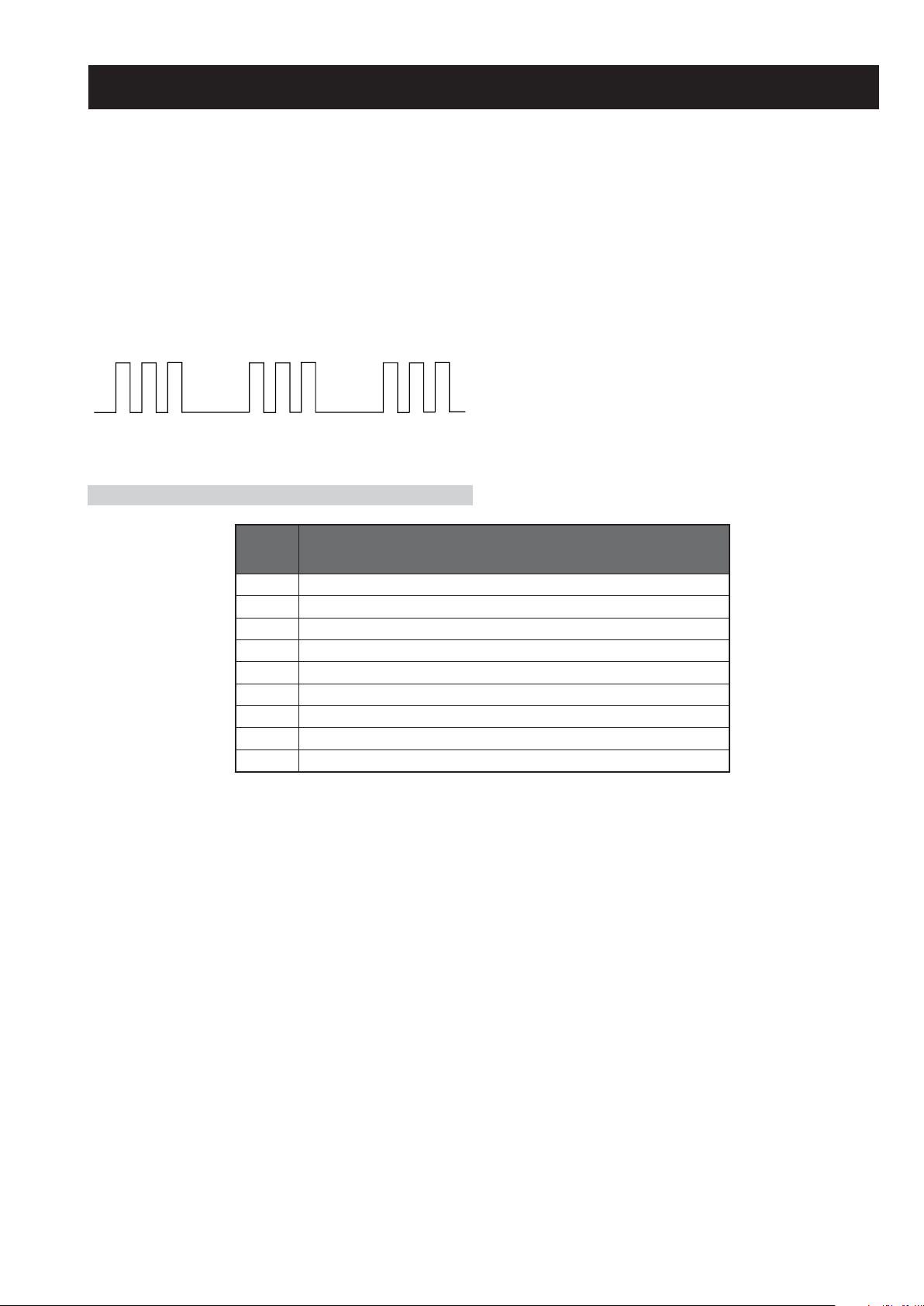
WAX2 SELF DIAGNOSTIC SOFTWARE
The identification of errors within the WAX2 chassis is triggered in one of two ways :- 1: Busy or 2: Device failure to respond to IIC. In the
event of one of these situations arising the software will first try to release the bus if busy (Failure to do so will report with a continuous
flashing LED) and then communicate with each device in turn to establish if a device is faulty. If a device is found to be faulty the relevant
device number will be displayed through the LED (Series of flashes which must be counted).
Flash Timing Example : e.g. error number 3
StBy LED
ON ON
OFF
LED Error Code
OFF
DEL
RORRE
EDOC
1)3TRELACD(elbuorTegatloVylppuSV33GERNU
2)2TRELACD(elbuorTegatloVV6/V5ED,8.1DV
3)1TRELACD(
4elbuorTthgilkcaB
5elbuorTegatloVylppuSniaM
6elbuorTegatloVdeilppArekaepS
7)
8elbuorTCItnedirT
9)TORP_SC_SB/snoitacinummoC(el
buorTTTD
elbuorTegatloVV5LENAP,V5.01GERNU
NOITPIRCSEDRORRE
edislenapehtno.pse(erutarepmeT-edisnIniesaercnInarotinoM
- 7 -
WAX2
RM-ED005
SECTION 1 GENERAL
(standby)
1
3,4
2
3,4
1
Continued
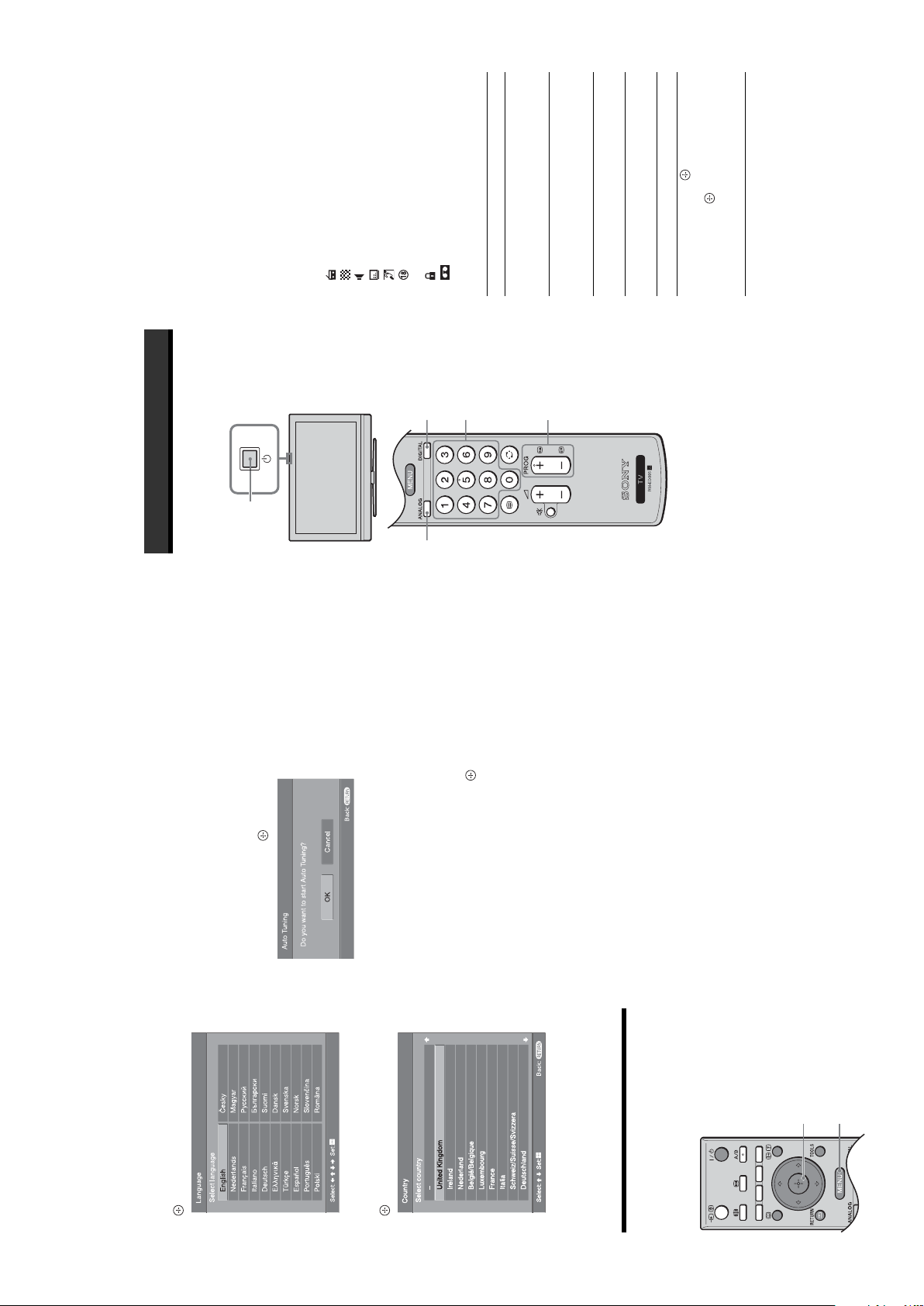
2
5: Selecting the
language and country/
region
3: Bundling the cables
Connect the TV to your mains socket (220-
240V AC, 50Hz).
Press 1 on the TV (top side).
1
2
4: Preventing the TV
from toppling over
indicator on the TV (front) is red), press "/1 on
When you switch on the TV for the first time, the
Language menu appears on the screen.
When the TV is in standby mode (the
the remote to switch on the TV.
2
1
3
(supplied)
Coaxial cable
The operating instructions mentioned here are partial abstracts
from the Operating Instruction Manual. The page numbers of
the Operating Instruction Manual remain as in the manual.
2: Connecting an aerial/
Start-up Guide
1: Checking the
onnecting an aerial only
VCR
accessories
Remote RM-ED005 (1)
Size AA batteries (R6 type) (2)
Mains lead (Type C-6) (1)
Coaxial cable (1)
Mains lead (supplied)
Cable holder (1)
Connecting an aerial and VCR
Support belt (1) and screws (2)
To insert batteries into the remote
RF lead
(not supplied)
VCR
Mains lead
(supplied)
Scart lead (not supplied)
Certain regions may regulate disposal of the battery.
Please consult your local authority.
and new batteries.
spill liquid of any kind onto it.
Notes
• Observe the correct polarity when inserting batteries.
• Dispose of batteries in an environmentally friendly way.
• Do not use different types of batteries together or mix old
• Handle the remote with care. Do not drop or step on it, or
• Do not place the remote in a location near a heat source, or
in a place subject to direct sunlight, or in a damp room.
– 8 –
WAX2
RM-ED005
Press the number buttons or PROG +/- to
select a TV channel.
To select channel numbers 10 and above using the
3
Watching TV
Watching TV
number buttons, enter the second and third digits
within two seconds.
1
To select a digital channel using the Digital
Electronic Programme Guide (EPG), see page 15.
In digital mode
An information banner appears briefly. The
following icons may be indicated on the banner.
:Radio service
F/f, then press
.
Press . To select an analogue
Press 1 on the TV (top side).
Turn off the TV
completely
- (decrease).
Adjust the volume Press 2 + (increase)/
Press %. Press 2 +/- to set the
temporarily
(Standby mode)
Turn on the TV
3
volume level.
from Standby mode
without sound
Press "/1.
programme (from 4 to 18 years)
: Scrambled/Subscription service
: Subtitles available
: Subtitles available for the hearing impaired
: Multiple audio languages available
: Recommended minimum age for current
: Current programme is being recorded
: Parental Lock
Additional operations
3
22
To Do this
Turn off the TV
channel, press
To access the Input signal index
table, see page 18.
Access the
Programme index
table (in analogue
Mute the sound Press %. Press again to restore.
mode only)
the TV.
When the TV is in standby mode (the 1 (standby)
indicator on the TV (front) is red), press "/1 on
the remote to switch on the TV.
Press 1 on the TV (top side) to switch on
1
Press DIGITAL to switch to digital mode or
ANALOG to switch to analogue mode.
The channels available vary depending on the
mode.
2
Continued
Before you start auto-tuning the TV, insert
a pre-recorded tape into the VCR
connected to the TV (page 4) and start play
back.
The video channel will be located and stored on
the TV during auto-tuning.
If no VCR is connected to the TV, this procedure
is not required. Go to step 2.
Select “OK”, then press .
1
to select the language
f
/
F
.
displayed on the menu screens, then press
Press
2
3
The TV starts searching for all available digital
channels, followed by all available analogue
channels. This may take some time, please be
patient and do not press any buttons on the TV or
remote.
If a message appears for you to confirm the aerial
connections
No digital or analogue channels were found.
Check all the aerial connections and press to
start auto-tuning again.
to select the country/region in
f
/
F
.
which you will operate the TV, then press
Press
4
– 9 –
When the Programme Sorting menu
appears on the screen, follow the steps of
“Programme Sorting” (page 28).
If you do not wish to change the order in which the
analogue channels are stored on the TV, go to step
4.
Press MENU to exit.
The TV has now tuned in all the available
channels.
3
4
If the country/region in which you want to use the
TV does not appear in the list, select “-” instead of
a country/region.
The message confirming the TV start auto-tuning
appears on the screen, then go to “6: Auto-tuning
the TV”.
6: Auto-tuning the TV
The TV will now search for and store all available TV
channels.
4
2
Using the Tools menu
Press TOOLS to display the following options when
viewing pictures from connected equipment other
than PC.
Options Description
WAX2
RM-ED005
Allows you to switch to digital
mode and obtain the time.
Power Saving See page 26.
Picture Mode See page 20.
Sound Mode See page 22.
Auto Clock Set (in
analogue mode only)
Sleep Timer See page 25.
i Volume See page 23.
R
/C
R
, P
B
/C
B
Press DIGITAL or ANALOG.
F/f,
g.) To
Press to access the Input signal
index table. (Then, only in
analogue mode, press
then press .
select an input source, press
Viewing pictures from
connected equipment
Switch on the connected equipment, then
perform one of the following operation.
For equipment connected to the scart sockets using a
fully-wired 21-pin scart lead
Start playback on the connected equipment.
The picture from the connected equipment appears on
the screen.
For an auto-tuned VCR (page 6)
In analogue mode, press PROG +/-, or the number
buttons, to select the video channel.
In digital mode, press to display the
Digital Electronic Programme Guide
(EPG).2Perform the desired operation, as shown in
the following table.
1
Note
Programme information will only be displayed if the TV
station is transmitting it.
For other connected equipment
Press / repeatedly until the correct input
symbol (see below) appears on the screen.
F/f/G/g.
AV1/ AV1, AV2/ AV2:
Audio/video or RGB input signal through the scart
socket / 1 or 2. appears only if an RGB
1 Press the blue button.
AV 3 :
source has been connected.
to select a category. The category name is
g
/
G
/
f
/
F
displayed on the side.
2 Press
AV 4 :
sockets / 3, and audio input signal through the
L, R sockets / 3.
Favourite list (page 17).
“All Categories”: Contains all available channels.
Digital audio/video signal is input through the HDMI IN
“News”: Contains all news channels.
3 Press .
Component input signal through the Y, P
The categories available include:
“Favourite”: Contains all the channels that have been stored in the
4 socket. Audio input signal is analogue only if the
equipment has been connected using the DVI and audio
out socket.
The Digital Electronic Programme Guide (EPG) now only displays the
current programmes from the category selected.
AV 5 / AV 5 :
to select the future programme you want to
g
/
G
/
f
/
F
record.
1 Press
Video input signal through the video socket 5, and
audio input signal through the L (MONO), R audio
sockets 5. appears only if the equipment is
to select “Timer REC”.
f
/
F
2 Press .
3 Press
connected to the S video socket 5 instead of the
video socket 5, and S video input signal is input
through the S video socket 5.
Additional operations
To Do this
Return to the normal
TV operation
Access the Input
signal index table
Continued
A symbol appears by that programme’s information. The
indicator on the TV (front) lights up.
VCRs. If your VCR is not Smartlink compatible, a message will be displayed to
remind you to set your VCR timer.
switch off the TV completely or the recording may be cancelled.
code will appear on the screen. For more details refer to “Parental Lock” on
4 Press to set the TV and your VCR timers.
• You can set VCR timer recording on the TV only for Smartlink compatible
Notes
page 32.
• Once a recording has begun, you can switch the TV to standby mode, but do not
• If an age restriction for programmes has been selected, a message asking for pin
Checking the Digital Electronic Programme Guide
(EPG) *
* Please note that this function may not be available in some countries.
Digital Electronic Programme Guide (EPG)
To Do this
Turn off the EPG Press .
Move through the EPG Press
Watch a current programme Press while the current programme is selected.
Sort the programme information by
category – Category list
Set a programme to be recorded – Timer
REC
– 10 –
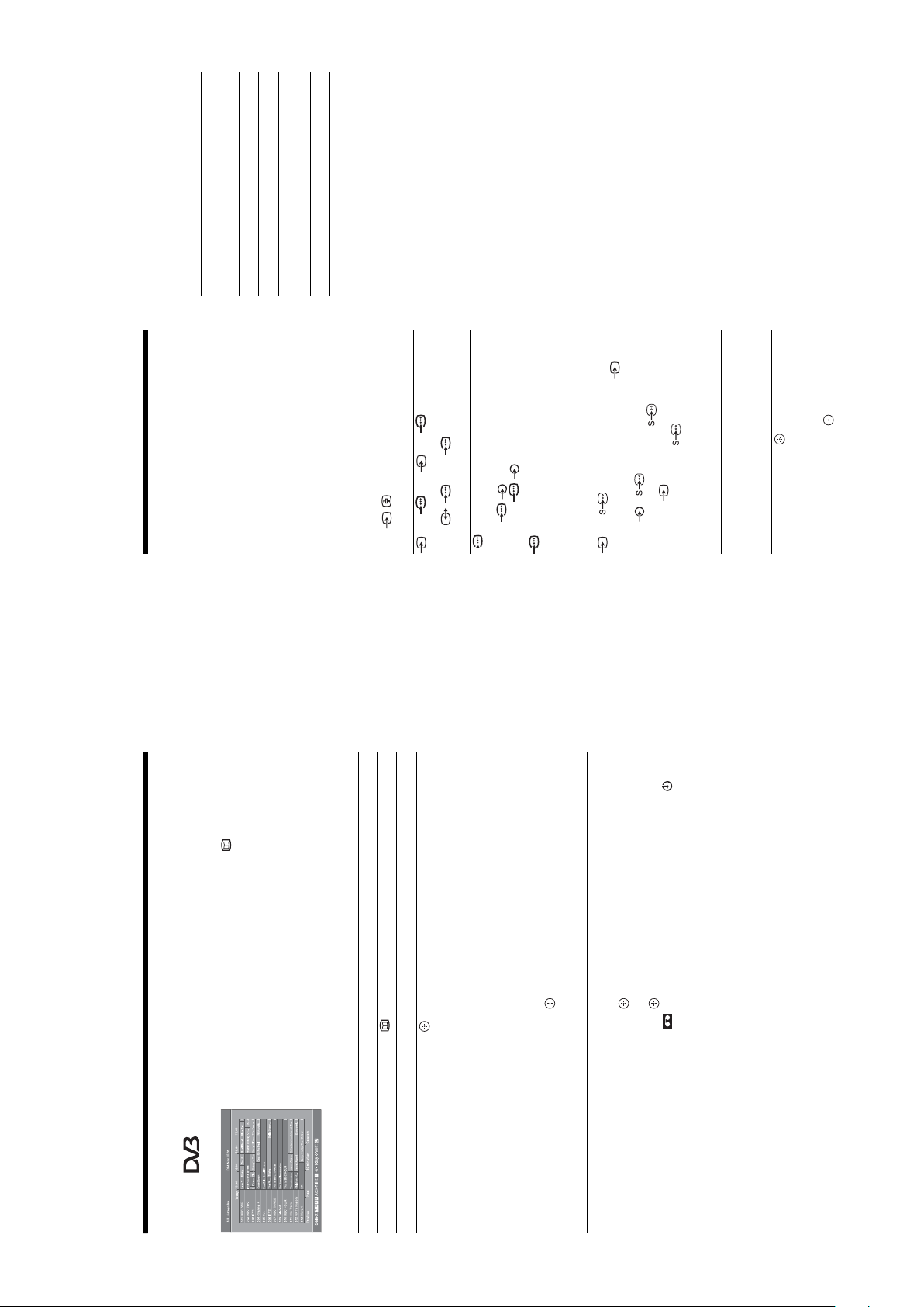
You can select the options listed below on the Picture
menu. To select options in “Settings”, see “Navigating
through menus” (page 19).
Selects whether to apply settings made in the Picture menu to all inputs, or only to
the input currently being watched.
“All”: Applies settings to all inputs.
“Viewing Only”: Applies settings only to the current input.
Selects the picture mode.
“Vivid”: For enhanced picture contrast and sharpness.
“Standard”: For standard picture. Recommended for home entertainment.
“Custom”: Allows you to store your preferred settings.
Resets all picture settings except “Picture Mode” to the factory settings.
Adjusts the brightness of the backlight.
Increases or decreases picture contrast.
Brightens or darkens the picture.
Increases or decreases colour intensity.
Increases or decreases the green tones.
Tip
“Hue” can only be adjusted for an NTSC colour signal (e.g., U.S.A. video tapes).
Adjusts the whiteness of the picture.
“Cool”: Gives the white colours a blue tint.
“Neutral”: Gives the white colours a neutral tint.
“Warm1”/“Warm2”: Gives the white colours a red tint. “Warm2” gives a redder tint
than “Warm1”.
Tip
“Warm1” and “Warm2” can only be selected when you set “Picture Mode” to “Custom”.
WAX2
RM-ED005
Sharpens or softens the picture.
Picture menu
Press MENU to display the menu.2Press
1
Target Inputs
to select an option.
f
/
F
Picture Mode
Press to confirm a selected option.
To exit the menu, press MENU.
Reset
Backlight
3
Contrast
Brightness
Colour
Hue
Colour Temperature
Sharpness
F/f/G/g.
2,3
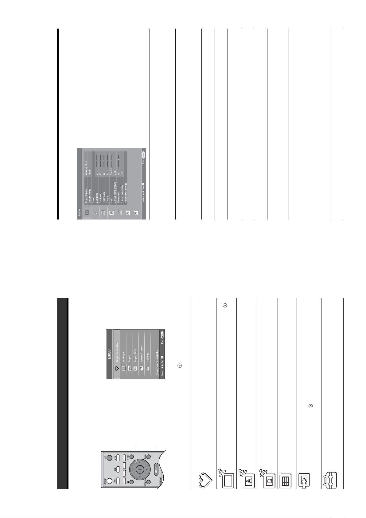
Using MENU Functions
Navigating through menus
“MENU” allows you to enjoy various convenient features of this TV. You can easily select channels or external
inputs with the remote. Also, settings for your TV can be changed easily using “MENU”.
Launches the Favourite list. For details about settings, see page 17.
Allows you to select TV programs from a list of channel labels.
• To watch the desired channel, select the channel, then press .
• To assign a label to a program, see page 28.
Returns to the last viewed analogue channel.
Returns to the last viewed digital channel.
Launches the Digital Electronic Programme Guide (EPG).
For details about settings, see page 15.
Selects equipment connected to your TV.
press .
• To watch the desired external input, select the input source, then
• To assign a label to an external input, see page 25.
Opens the Settings menu screen where most of advanced settings and
adjustments are performed. Select a menu icon, select an option and make the
desired change or adjustment using
For details about settings, see page 20 to 32.
1
Analogue
(only in areas with
– 11 –
Digital Favourites
Menu Description
(only in areas with
digital broadcasting)
Programme List
(only in areas with
analogue broadcasting)
digital broadcasting)
Digital
(only in areas with
digital broadcasting)
Digital EPG
(only in areas with
digital broadcasting)
External Inputs
Settings
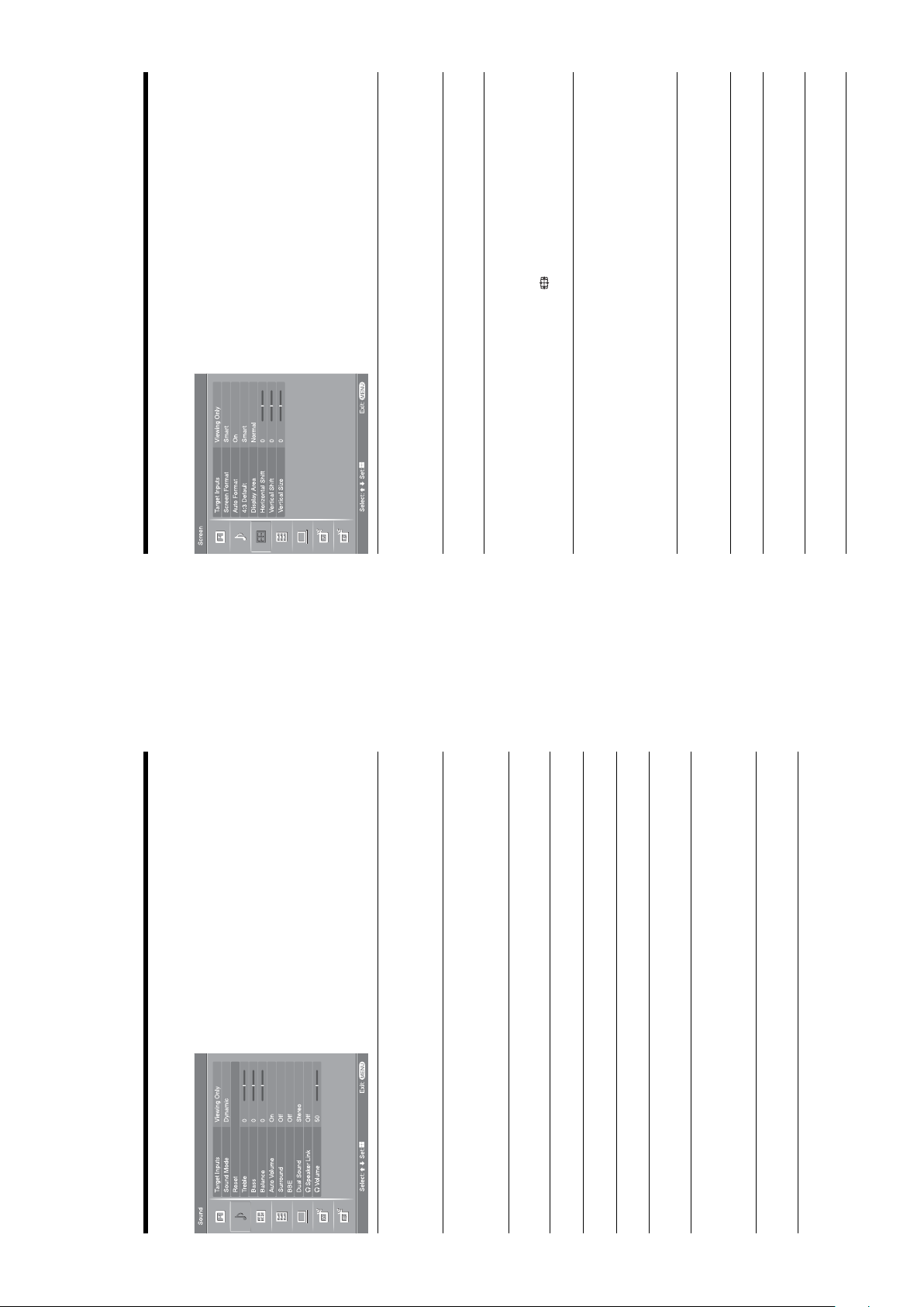
You can select the options listed below on the Screen
menu. To select options in “Settings”, see “Navigating
through menus” (page 19).
WAX2
RM-ED005
Screen menu
Selects whether to apply settings made in the Screen menu to all inputs, or only to
the input currently being watched.
“All”: Applies settings to all inputs.
“Viewing Only”: Applies settings only to the current input.
Target Inputs
For details about the screen format, see “To change the screen mode manually to suit
the broadcast” (page 14).
Automatically changes the screen format according to the broadcast signal. To keep
your setting, select “Off”.
Tips
Screen Format
Auto Format
format of the screen by pressing repeatedly.
• Even if you have selected “On” or “Off” in “Auto Format”, you can always modify the
• “Auto Format” is available for PAL and SECAM signals only.
Selects the default screen mode for use with 4:3 broadcasts.
“Smart”: Displays conventional 4:3 broadcasts with an imitation wide screen effect.
“4:3”: Displays conventional 4:3 broadcasts in the correct proportions.
“Off”: Keeps the current “Screen Format” setting when the channel or input is
changed.
4:3 Default
Tip
This option is available only if “Auto Format” is set to “On”.
Adjusts the screen area displaying the picture.
“Normal”: Displays the picture in the original size.
“–1”/“–2”: Enlarges the picture to hide the edge of the picture.
Adjusts the horizontal position of the picture for each screen format.
Display Area
Horizontal Shift
Adjusts the vertical position of the picture when the screen format is set to Zoom or
14:9.
Adjusts the vertical size of the picture when the screen format is set to Smart, Zoom
or 14:9.
Vertical Shift
Vertical Size
You can select the options listed below on the Sound
menu. To select options in “Settings”, see “Navigating
through menus” (page 19).
Sound menu
Selects whether to apply settings made in the Sound menu to all inputs, or only to the
input currently being watched.
“All”: Applies settings to all inputs.
“Viewing Only”: Applies settings only to the current input.
Target Inputs
Selects the sound mode.
“Dynamic”: Enhances treble and bass.
“Standard”: For standard sound. Recommended for home entertainment.
“Custom”: Flat response. Also allows you to store your preferred settings.
Sound Mode
– 12 –
Resets the sound settings except “Sound Mode”, “Dual Sound”, “i Speaker Link”
and “i Volume” to the factory settings.
Reset
Adjusts higher-pitched sounds.
Treble
Adjusts lower-pitched sounds.
Bass
Emphasizes left or right speaker balance.
Balance
Keeps a constant volume level even when volume level gaps occur (e.g., adverts tend
to be louder than programmes).
Selects the surround mode.
“TruSurround XT”: For surround sound (for stereo programmes only).
Auto Volume
Surround
“Simulated Stereo”: Adds a surround-like effect to mono programs.
“Off”: For normal stereo or mono reception.
Gives sound more impact by compensating for phase effects in speakers using the
“BBE High Definition Sound System”.
BBE
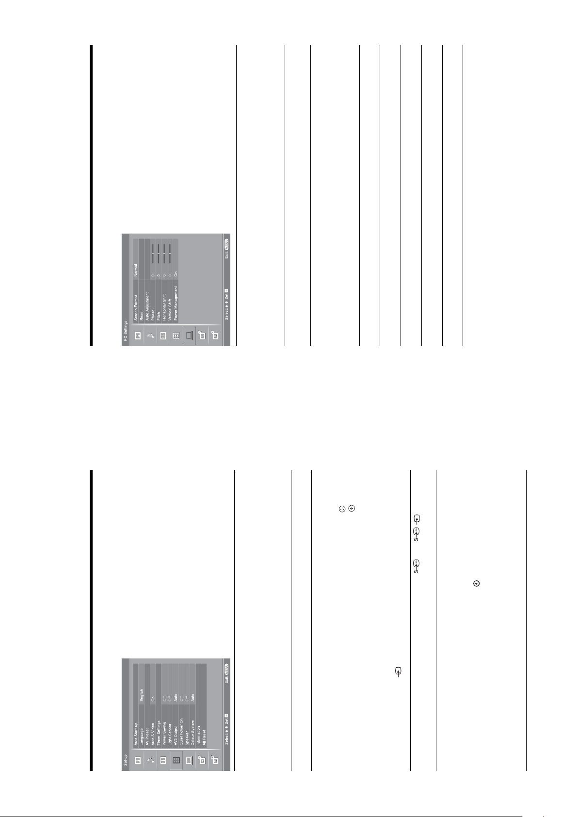
You can select the options listed below on the PC
Settings menu. To select options in “Settings”, see
“Navigating through menus” (page 19).
WAX2
RM-ED005
Selects a screen mode for displaying input from your PC.
“Normal”: Displays the picture in its original size.
“Full1”: Enlarges the picture to fill the display area, keeping its original horizontal-
to-vertical aspect ratio.
“Full2”: Enlarges the picture to fill the display area.
Resets the PC settings except “Screen Format” and “Power Management” to the
factory settings.
Automatically adjusts the display position and phase of the picture when the TV
receives an input signal from the connected PC.
Tip
Auto Adjustment may not work well with certain input signals. In such cases, manually adjust
“Phase”, “Pitch”, “Horizontal Shift” and “Vertical Shift”.
Adjusts the phase when the screen flickers.
Adjusts the pitch when the picture has unwanted vertical stripes.
Adjusts the horizontal position of the picture for each screen format.
Adjusts the vertical position of the picture for each screen format.
Switches the TV to standby mode if no signal is received for 30 seconds.
PC Settings menu
You can select the options listed below on the Set-up
menu. To select options in “Settings”, see “Navigating
through menus” (page 19).
Screen Format
Reset
Auto Adjustment
Phase
Pitch
Horizontal Shift
Vertical Shift
5 when / 5 sockets are both
Power Management
Continued
Set-up menu
Starts the “first time operation menu” to select the language and country/region, and
tune in all available digital and analogue channels. Usually, you do not need to do
this operation because the language and country/region will have been selected and
channels already tuned when the TV was first installed (page 5, 6). However, this
option allows you to repeat the process (e.g., to retune the TV after moving house,
Auto Start-up
or to search for new channels that have been launched by broadcasters).
– 13 –
Selects the language in which the menus are displayed.
Assigns a name to any equipment connected to the side and rear sockets. The name
will be displayed briefly on the screen when the equipment is selected. You can skip
Language
AV Preset
to select the desired input source, then press .
to select the desired option below, then press .
f
f
/
/
F
F
2 Press
an input source that is not connected to any equipment.
1 Press
Equipment labels: Uses one of the preset labels to assign a name to connected
equipment.
“Edit”: Creates your own label. Follow steps 2 to 4 of “Programme Labels”
(page 28).
“Skip”: Skips an input source that is not connected to any equipment when you press
to select the input source.
connected.
Selects the input signal from S video sockets
Sets the timer to turn on/off the TV.
Sleep Timer
Auto S Video
Timer Settings
Sets a period of time after which the TV automatically switches itself into standby
mode.
When the Sleep Timer is activated, the (Timer) indicator on the TV (front) lights
up in orange.
switches to standby mode.
Tips
• If you switch off the TV and switch it on again, “Sleep Timer” is reset to “Off”.
• “TV will soon turn off by sleep timer.” appears on the screen one minute before the TV

to display the following menus. To select options
You can change/set the digital settings using the
Digital Set-up menu. Select “Digital Set-up” and press
in “Settings”, see “Navigating through menus”
(page 19).
WAX2
RM-ED005
Continued
to select the channel
f
/
F
to tune the channel.
f
/
F
G to select “Yes”, then press .
Digital Set-up menu
Displays the “Digital Tuning” menu.
Digital Auto Tuning
Tunes in all the available digital channels.
Usually you do not need to do this operation because the channels are already tuned
when the TV was first installed (page 6). However, this option allows you to repeat
Digital Tuning
the process (e.g., to retune the TV after moving house, or to search for new channels
that have been launched by broadcasters).
Programme List Edit
Removes any unwanted digital channels stored on the TV, and changes the order of
to select the channel you want to remove or move to a new
f
/
F
position.
If you know the programme number (frequency)
the digital channels stored on the TV.
1 Press
Press the number buttons to enter the three-digit programme number of the broadcast
To remove the digital channel
you want.
Press . A message that confirms whether the selected digital channel is to be
2 Remove or change the order of the digital channels as follows:
deleted appears. Press
To change the order of the digital channels
Press g, then press F/f to select the new position for the channel and press G.
Repeat the procedure in steps 1 and 2 to move other channels if required.
manually tune, then press
3 Press RETURN.
Digital Manual Tuning
Tunes the digital channels manually.
1 Press the number button to select the channel number you want to
2 When the available channels are found, press
to select the programme number where you want to store the
f
/
F
you want to store, then press .
new channel, then press .
3 Press
Repeat the procedure above to tune other channels manually.
You can change/set the analogue settings using the
Analogue Set-up menu. To select options in
“Settings”, see “Navigating through menus”
(page 19).
to select the channel you want to move to a new position,
to select the new position for your channel, then press .
f
f
/
/
F
F
then press .
When “1 Digit Direct” is set to “On”, you can select an analogue channel using one
preset number button (0 - 9) on the remote.
Note
When “1 Digit Direct” is set to “On”, you cannot select channel numbers 10 and above entering
two digits using the remote.
Tunes in all the available analogue channels.
Usually you do not need to do this operation because the channels are already tuned
when the TV was first installed (page 5, 6). However, this option allows you to
repeat the process (e.g., to retune the TV after moving house, or to search for new
channels that have been launched by broadcasters).
Analogue Set-up menu (Analogue mode only)
1 Digit Direct
Auto Tuning
2 Press
Changes the order in which the analogue channels are stored on the TV.
1 Press
Programme Sorting
– 14 –
.
g
to select the channel you want to name, then press .
to select the desired letter or number (“_” for a blank space),
f
f
/
/
F
F
then press
If you input a wrong character
Assigns a channel name of your choice up to five letters or numbers. The name will
2 Press
be displayed briefly on the screen when the channel is selected. (Names for channels
are usually taken automatically from Text (if available).)
1 Press
Programme Labels
character.
Press G/g to select the wrong character. Then, press F/f to select the correct
To delete all the characters
.
Select “Reset”, then press
3 Repeat the procedure in step 2 until the name is complete.
4 Select “OK”, then press .
WAX2
RM-ED005
sockets. It is recommended to use
a PC cable with ferrites.
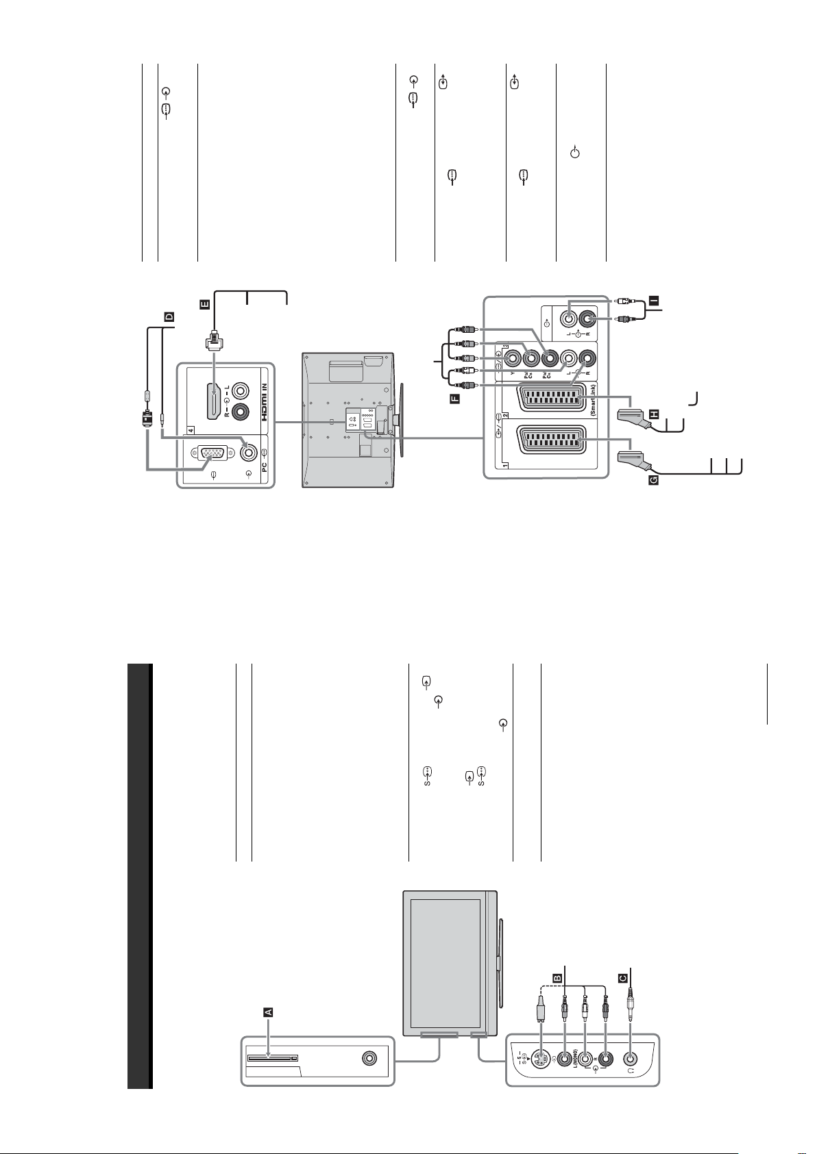
To connect Do this
PC D Connect to the PC /
PC
Connecting to the TV (rear)
Connect to the HDMI IN 4 socket
Digital satellite
if the equipment has a HDMI
socket. The digital video and audio
receiver or DVD
player E
signals are input from the
equipment. If the equipment has a
DVD player
DVI socket, connect the DVI
1. When you connect the
socket to the HDMI IN 4 socket
through a DVI - HDMI adaptor
interface (not supplied), and
connect the equipment’s audio out
sockets to the audio in HDMI IN 4
sockets.
Digital satellite receiver
Note
The HDMI sockets only support the
following video inputs: 480i, 480p,
576i, 576p, 720p and 1080i. To
connect a PC, please use the PC input
socket.
Connect to the component sockets
and the audio sockets / 3.
DVD player with
component output
DVD player
Connect to the scart socket /
decoder, the scrambled signal from
the TV tuner is output to the
F
Video game
equipment, DVD
player or decoder
G
with component output
decoder, then the unscrambled
signal is output from the decoder.
Connect to the scart socket /
DVD recorder or
2. SmartLink is a direct link
between the TV and a VCR/DVD
recorder.
VCR that supports
SmartLink H
Connect to the audio output
sockets to listen to the sound
from the TV on Hi-Fi audio
equipment.
Hi-Fi audio
equipment I
Hi-Fi
Decoder
VCR
DVD recorder
DVD player
Decoder
Video game equipment
To use Pay Per View services.
For details, refer to the instruction
manual supplied with your CAM.
To use the CAM, remove the
rubber cover from the CAM slot.
Switch off the TV when inserting
your CAM into the CAM slot.
When you do not use the CAM, we
recommend that you replace the
To connect Do this
Conditional Access
Module (CAM) A
Using Optional Equipment
Connecting optional equipment
You can connect a wide range of optional equipment to your TV. Connecting cables are not supplied.
Connecting to the TV (side)
CAM is not supported in all
cover on the CAM slot.
Note
5 or the video socket 5,
Connect to the S video socket
authorized dealer.
and the audio sockets 5. To
S VHS/Hi8/DVC
camcorder B
countries. Please check with your
avoid picture noise, do not connect
Continued
5 at the same time. If you
5 and the S video socket
connect mono equipment, connect
to the L socket 5.
Headphones C Connect to the i socket to listen to
sound from the TV on headphones.
S VHS/Hi8/DVC
camcorder
Headphones
the camcorder to the video socket
– 15 –

SU-WL51 (for KDL-46V2000/KDL-40V2000)
SU-WL31 (for KDL-32V2000)
Optional Accessories
• Wall-Mount Bracket
Design and specifications are subject to change
without notice.
Standard
Vertical
frequency (Hz)
Horizontal
frequency
(kHz)
WAX2
RM-ED005
640 480 37.5 75 VESA
720 400 31.5 70 VGA-T
800 600 46.9 75 VESA
1024 768 56.5 70 VESA
1024 768 60 75 VESA
1280 768 47.8 60 VESA
1360 768 47.7 60 VESA
10 W + 10 W
Sound Output
Supplied Accessories
Refer to “1: Checking the accessories” on page 4.
Colour/Video System
PC Input Signal Reference Chart
NTSC 3.58, 4.43 (only Video In)
Analogue: PAL, SECAM
Digital: MPEG-2 MP@ML
Aerial
75 ohm external terminal for VHF/UHF
Signals Horizontal (Pixel) Vertical (Line)
UHF: E21–E69
Channel Coverage
Analogue: VHF: E2–E12
VGA 640 480 31.5 60 VGA
CATV: S1–S20
HYPER: S21–S41
D/K: R1–R12, R21–R69
L: F2–F10, B–Q, F21–F69
I: UHF B21–B69
SVGA 800 600 37.9 60 VESA Guidelines
Digital: VHF/UHF
Terminals
XGA 1024 768 48.4 60 VESA Guidelines
/1
21-pin Scart connector (CENELEC standard) including
audio/video input, RGB input, and TV audio/video
WXGA 1280 768 47.4 60 VESA
/ 2 (SmartLink)
output.
3
21-pin Scart connector (CENELEC standard) including
audio/video input, RGB input, selectable audio/video
output, and SmartLink interface.
and play, signals with a 60 Hz vertical frequency will be selected automatically.
• This TV’s PC input does not support Sync on Green or Composite Sync.
• This TV’s PC input does not support interlaced signals.
• This TV’s PC input supports the boldfaced signals in the above chart with a 60 Hz vertical frequency.
• For the best picture quality, it is recommended to use signals with a 60 Hz vertical frequency from a personal computer. In plug
32, 44.1 and 48 kHz, 16, 20 and 24 bits,
or analogue audio input (phono jacks)
Audio output (Left/Right) (phono jacks)
B/CB: 0.7 Vp-p, 75 ohmsPR/CR: 0.7 Vp-p, 75 ohms
3
Audio input (phono jacks)
500 mVrms
Impedance: 47 kilo ohms
Supported formats: 1080i, 720p, 576p, 576i, 480p, 480i
Y: 1 Vp-p, 75 ohms, 0.3V negative sync
P
Video: 1080i, 720p, 576p, 576i, 480p, 480i
HDMI IN 4
Audio: Two channel linear PCM
5 S video input (4-pin mini DIN)
5 Video input (phono jack)
5 Audio input (phono jacks)
G: 0.7 Vp-p, 75 ohms, non Sync on Green
PC PC Input (15 Dsub) (see page 37)
B: 0.7 Vp-p, 75 ohms, non Sync on Green
R: 0.7 Vp-p, 75 ohms, non Sync on Green
PC audio input (minijack)
HD: 1-5 Vp-p
VD: 1-5 Vp-p
CAM (Conditional Access Module) slot
i Headphones jack
220–240 V AC, 50 Hz
Additional Information
Specifications
Display Unit
Power Requirements:
KDL-46V2000:
Screen Size:
B/G/H, D/K, L, I
46 inches (Approx. 116.9 cm measured diagonally)
40 inches (Approx. 101.6 cm measured diagonally)
32 inches (Approx. 80.1 cm measured diagonally)
KDL-40V2000:
KDL-32V2000:
1,366 dots (horizontal) × 768 lines (vertical)
KDL-46V2000: 250 W
KDL-40V2000: 180 W
KDL-32V2000: 145 W
Display Resolution:
Power Consumption:
Standby Power Consumption:
0.3 W
Approx. 1,120 × 805 × 334 mm (with stand)
Approx. 1,120 × 755 × 116 mm (without stan d)
Approx. 988 × 716 × 334 mm (with stand)
Approx. 988 × 664 × 103 mm (without stand)
Approx. 792 × 593 × 219 mm (with stand)
Approx. 792 × 546 × 99 mm (without stand)
Approx. 34 kg (with stand)
Approx. 28 kg (without stand)
Approx. 27 kg (with stand)
Approx. 21 kg (without stand)
Approx. 17 kg (with stand)
Approx. 15 kg (without stand)
KDL-46V2000:
KDL-40V2000:
KDL-32V2000:
KDL-46V2000:
KDL-40V2000:
KDL-32V2000:
Dimensions (w × h × d):
Mass:
Panel System
LCD (Liquid Crystal Display) Panel
TV System
Analogue: Depending on your country/region selection:
Digital: DVB-T
– 16 –
• Press 2 +/– or % (Mute).
• Check that “Speaker” is set to “On” in the “Set-up” menu (page 26).
• See the “Picture noise” causes/remedies on page 38.
analogue channel.
• Switch between digital and analogue mode and select the desired digital/
service.
• Scrambled/Subscription only channel. Subscribe to the Pay Per View
your area.
• Channel is used only for data (no picture or sound).
• Contact the broadcaster for transmission details.
• Contact a local installer to find out if digital transmissions are provided in
• Upgrade to a higher gain aerial.
• Check if the “Sleep Timer” is activated, or confirm the “Duration” setting of
“On Timer” (page 25).
• If no signal is received and no operation is performed in the TV mode for
10 minutes, the TV automatically switches to standby mode.
• Check if the “On Timer” is activated (page 26).
• Select “AV Preset” in the “Set-up” menu and cancel “Skip” of the input
WAX2
RM-ED005
source (page 25).
• Replace the batteries.
Sound
Problem Cause/Remedy
No sound, but good picture
Noisy sound
Channels
Problem Cause/Remedy
The desired channel cannot be
selected
Some channels are blank
Digital channel is not displayed
General
Problem Cause/Remedy
The TV turns off automatically
(the TV enters standby mode)
The TV turns on automatically
Some input sources cannot be
selected
The remote does not function
jacks of 3.
R
/C
R
, P
B
jacks of 3 are firmly seated in their
R
/C
B
/C
R
, P
B
/C
B
Sony service centre of how the indicator flashes (duration and interval).
For example, the indicator flashes for two seconds, stops flashing for one second, and flashes for two seconds.
Troubleshooting
Check whether the 1 (standby) indicator is flashing in red.
When it is flashing
The self-diagnosis function is activated.
1 Measure how long the 1 (standby) indicator flashes and stops flashing.
2 Press 1 on the TV (top side) to switch it off, disconnect the mains lead, and inform your dealer or
When it is not flashing
the correct input symbol is displayed on the screen.
• If the 1 (standby) indicator lights up in red, press "/1.
• Check the aerial connection.
• Connect the TV to the mains, and press 1 on the TV (top side).
• Check that the optional equipment is on and press / repeatedly until
• Check the connection between the optional equipment and the TV.
• Check aerial/cable connections.
2 If the problem still persists, have your TV serviced by qualified service personnel.
Picture
Problem Cause/Remedy
No picture (screen is dark) and
no sound
No picture or no menu
information from equipment
connected to the scart
connector
Double images or ghosting
1 Check the items in the tables below.
• Check the aerial location and direction.
years in normal use, one to two years at the seaside).
hair-dryers or optical equipment.
• Keep the TV away from electrical noise sources such as cars, motorcycles,
Distorted picture (dotted lines
or stripes)
equipment and the TV.
• When installing optional equipment, leave some space between the optional
• Check if the aerial is broken or bent.
• Check if the aerial has reached the end of its serviceable life (three to five
Only snow and noise appear
on the screen
adjust “AFT” (Automatic Fine Tuning) to obtain better picture reception
• Make sure that the aerial is connected using the supplied coaxial cable.
• Keep the aerial cable away from other connecting cables.
• Select “Manual Programme Preset” in the “Analogue Set-up” menu and
Picture noise when viewing a
TV channel
(page 29).
bright points (pixels) on the screen do not indicate a malfunction.
• The picture of a display unit is composed of pixels. Tiny black points and/or
Some tiny black points and/or
bright points on the screen
(page 20).
• Select “Reset” in the “Picture” menu to return to the factory settings
No colour on programmes
• Check the connection of the Y, P
No colour or irregular colour
respective sockets.
• Make sure that the Y, P
jacks of 3
R
/C
R
, P
B
/C
B
when viewing a signal from the
Y, P
– 17 –
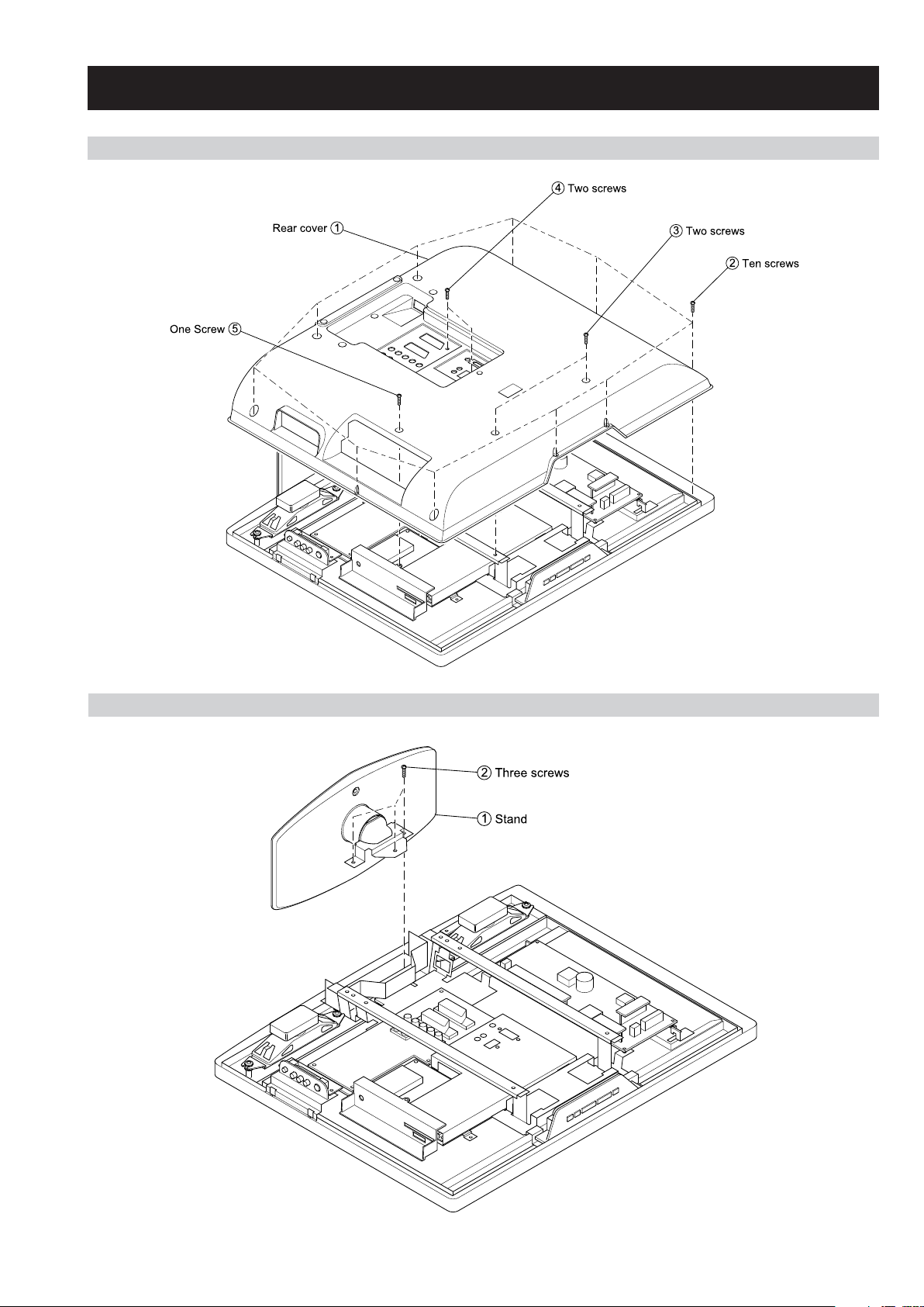
2-1. REAR COVER REMOVAL
WAX2
RM-ED005
SECTION 2 DISASSEMBLY
2-2. STAND REMOVAL
– 18 –
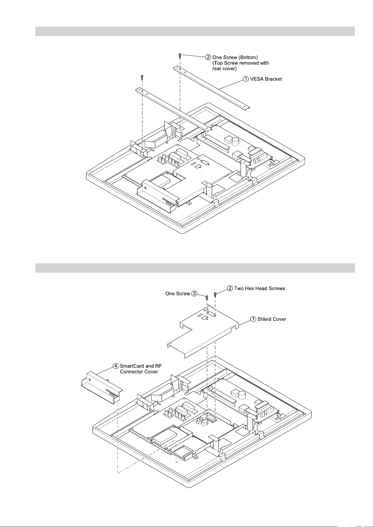
2-3. VESA BRACKET REMOVAL
WAX2
RM-ED005
2-4. SHIELD COVER REMOVAL
– 19 –
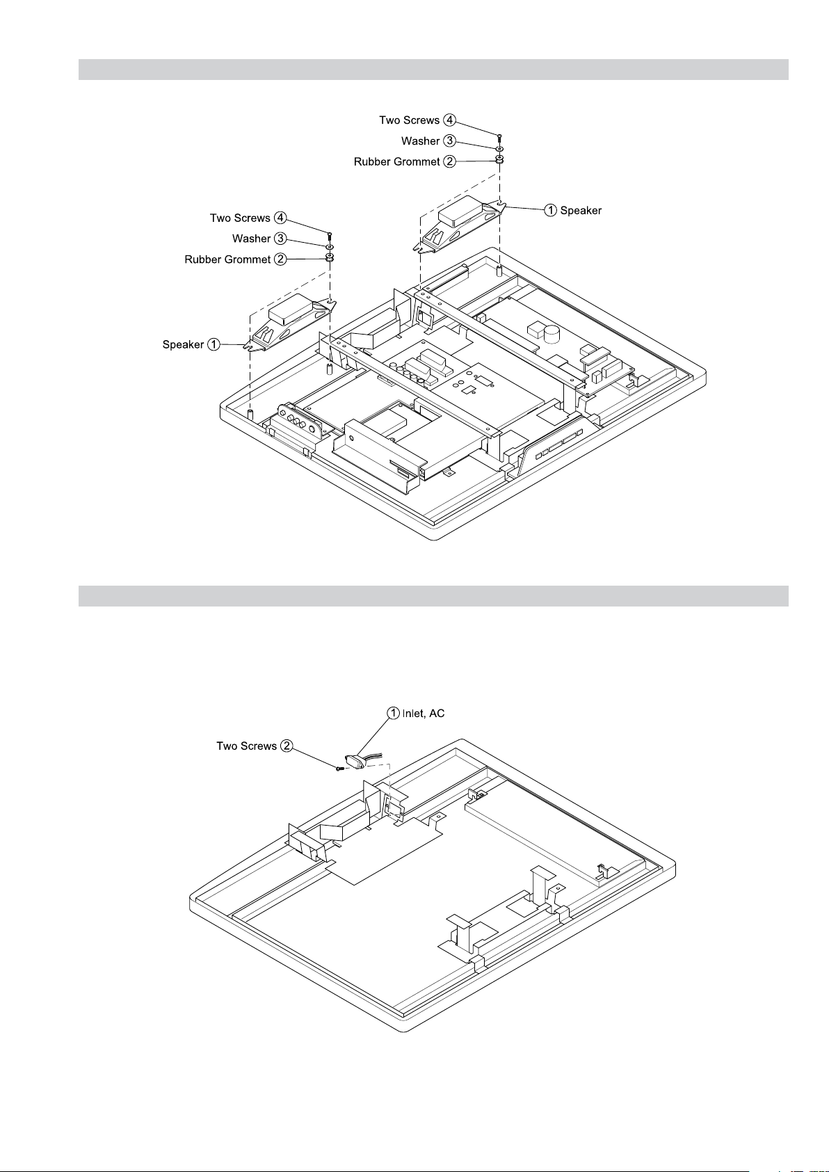
2-5. SPEAKER REMOVAL
WAX2
RM-ED005
2-6. AC INLET REMOVAL
– 20 –
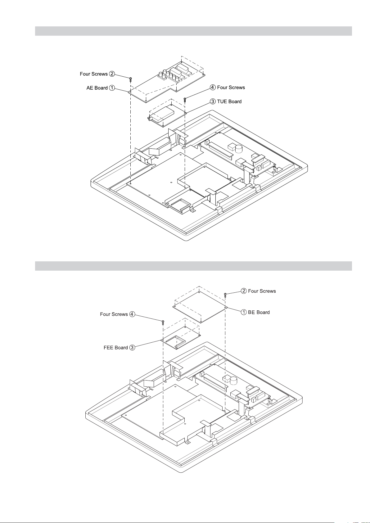
2-7. AE and TUE BOARD REMOVAL
WAX2
RM-ED005
2-8. BE and FEE BOARD REMOVAL
– 21 –
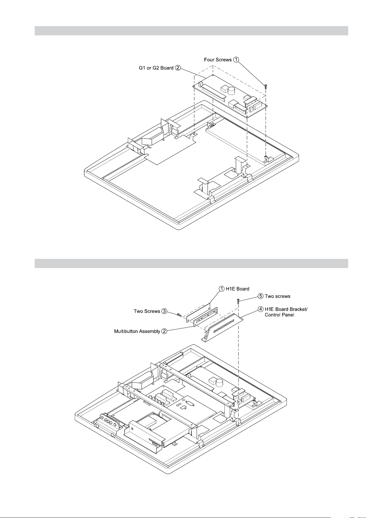
2-9. G1 or G2 BOARD REMOVAL
WAX2
RM-ED005
2-10. H1E BOARD REMOVAL
– 22 –
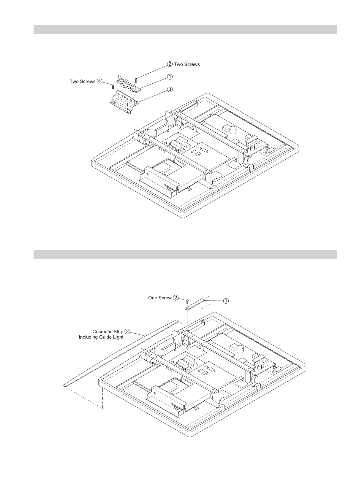
2-11. H2E or H46E BOARD REMOVAL
H2E or H46E Board
H2E or H46E Board Bracket
H4E Board
WAX2
RM-ED005
H2E or H46E Board
H2E or H46E Board Bracket
2-12. H4E BOARD REMOVAL
H4E Board
– 23 –
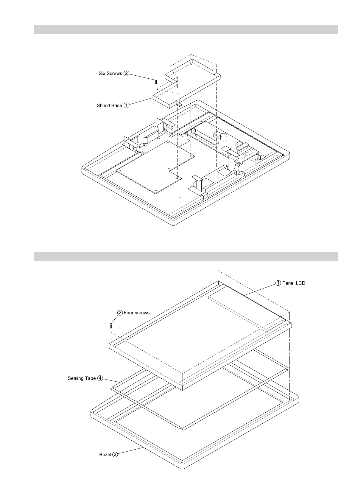
2-13. SHIELD BASE REMOVAL
WAX2
RM-ED005
2-14. LCD PANEL REMOVAL
– 24 –
SECTION 3 SET-UP ADJUSTMENTS
㧜
㧞㧟㧠㧡㧢㧣
WAX2
RM-ED005
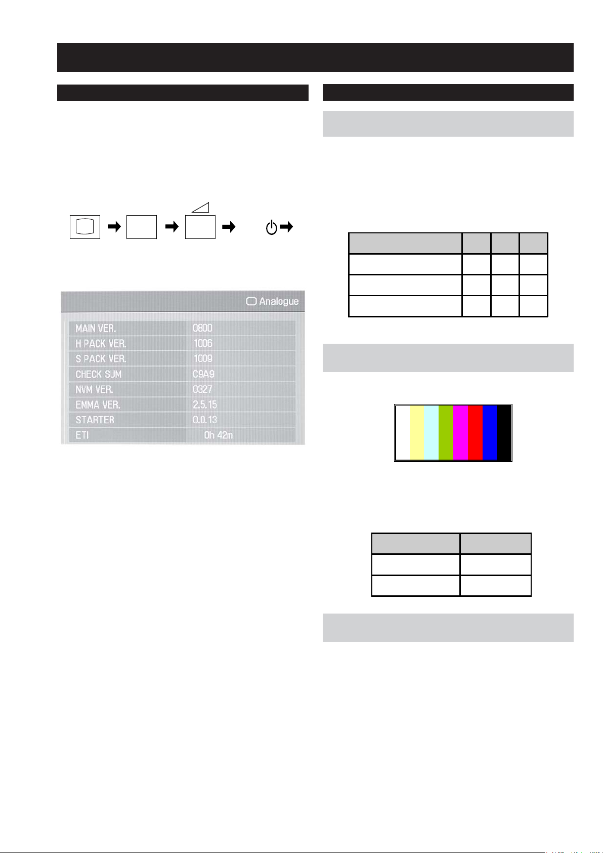
3-1. How to enter Service Mode
Service adjustments to this model can be performed using the
supplied remote Commander RM-ED005.
1. Turn on the power to the TV set and enter into the stand-by
mode.
2. Press the following sequence of buttons on the Remote
Commander.
i+
(ON SCREEN (DIGIT 5) (VOLUME +) (TV)
DISPLAY)
3. The following menu will then appear on the screen.
5
+
TV
I/
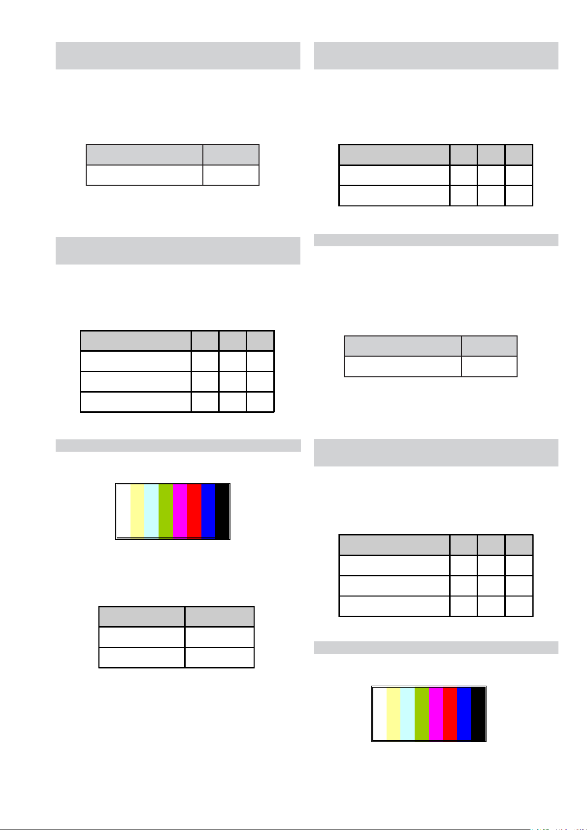
3-2. Signal Level Adjustment
Set up of AD calibration1 adjustment for
3-2-1.
terrestrial analog.
The following adjustments are done via ECS.
1. Send ECS_ADJUST_LEVEL_SETTING_INIT command.
2. Ensure noise reduction NR=3 (High), GAMMA_EN=0,
P4_CVD2_85=0.
3. Set the following registration items.
Screen Size 32" 40" 46"
TARGET_Y_RF(PAL) 165 165 165
ADJ_COLOR_Y_ATT(PAL) 128 128 128
ADJ_COLOR_PAL(PAL) 3 3 3
3-2-2.
Y signal calibration1 adjustment for
terrestrial analog.
1. Input PAL colour bar 75%Y, 75%C via terrestrial input.
4. Move to the relevant command using the up or down arrow
buttons on the remote commander.
5. Press the right arrow button to enter into the required menu item.
6. Press the ‘Menu’ button on the remote commander to quit the
Service Mode when all adjustments have been completed.
Note :
• After carrying out the service adjustments, to prevent the
customer accessing the ‘Service Menu’ switch the TV set OFF
and then ON.
2. Send ECS_ADJUST_TCD3_CONT_RF command.
3. Read the value of S-REG:APL_LUMA via ECS. Confirming that
the value is within spec of the table below.
AD-Adjust RF Spec Spec.
Reference register name
S-REG: APL_LUMA TARGET_Y_RF±2
Set up of C signal calibration1 adjustment
3-2-3.
for terrestrial analog.
1. Input PAL colour bar 75%Y, 75%C via terrestrial input.
2. Send ECS_ADJUST_LEVEL_SETTING_INIT command.
3. Ensure noise reduction NR=3 (High), GAMMA_EN=0,
P4_CVD2_85=0.
- 25 -
3-2-4.
㧜
㧞㧟
㧠㧡㧢㧣
㧜
㧞㧟㧠㧡㧢㧣
C signal calibration1 adjustment for
terrestrial analog.
3-2-7.
Set up of C signal calibration1 adjustment
for video.
WAX2
RM-ED005
1. Send ECS_ADJUST_TCD3_HUE_RF command.
2. Read S-REG: READ_BACK_B00 via ECS. (READ_AREA=0).
3. Read S-REG: READ_BACK_B01 via ECS. (READ_AREA=6).
4. Confirm that 8 bits of MSB of item number 2) and 3) are within
spec of the table below.
metIecnerefeR .cepS
eulavecnereffid*0B_KCAB_DAER2±
5. Switch the TV set OFF and then ON again to retain adjustment
values.
3-2-5.
Set up of AD calibration1 adjustment for
video.
1. Send ECS_ADJUST_LEVEL_SETTING_INIT command.
2. Ensure noise reduction NR=1 (Low), GAMMA_EN=0,
P4_CVD2_85=0.
3. Set the following registration items.
Screen Size 32" 40" 46"
TARGET_Y_V(PAL) 165 165 165
ADJ_COLOR_Y_ATT(PAL) 128 128 128
ADJ_COLOR_PAL(PAL) 3 3 3
1. Input PAL colour bar 75%Y, 75%C via AV1 input.
2. Send ECS_ADJUST_LEVEL_SETTING_INIT command.
3. Ensure noise reduction NR=1 (Low), GAMMA_EN=0,
P4_CVD2_85=0.
4. Set the following registration items.
Screen Size 32" 40" 46"
ADJ_COLOR_Y_ATT(PAL) 128 128 128
ADJ_COLOR_PAL(PAL) 3 3 3
C signal calibration1 adjustment for video.
3-2-8.
1. Send ECS_ADJUST_TCD3_HUE_V command.
2. Read S-REG: READ_BACK_B00 via ECS. (READ_AREA=0).
3. Read S-REG: READ_BACK_B01 via ECS. (READ_AREA=6).
4. Confirm that 8 bits of MSB of item number 2) and 3) are within
spec of the table below.
metIecnerefeR .cepS
eulavecnereffid*0B_KCAB_DAER2±
5. Read S-REG: TCD3_SATURATION via ECS.
6. Switch the TV set OFF and then ON again to retain adjustment
values.
3-2-6.
Y signal calibration1 adjustment for video.
1. Input PAL colour bar 75%Y, 75%C via AV1 input.
㧠㧡㧢㧣
2. Send ECS_ADJUST_TCD3_CONT_V command.
3. Read the value of S-REG:APL_LUMA via ECS. Confirming that
the value is within spec of the table below.
AD-Adjust Video Spec Spec.
Reference register name
S-REG: APL_LUMA TARGET_Y_V±2
3-2-9.
Set up of AD calibration2 adjustment for
video.
1. Send ECS_ADJUST_LEVEL_SETTING_INIT command.
2. Ensure noise reduction NR=1 (Low), GAMMA_EN=0,
P4_CVD2_85=0.
3. Set the following registration items.
Screen Size 32" 40" 46"
TARGET_Y_V(SECAM) 165 165 165
ADJ_COLOR_Y_ATT(SECAM) 128 128 128
ADJ_COLOR_PAL(SECAM) 2 2 2
3-2-10.
Y signal calibration2 adjustment for video.
1. Input SECAM colour bar 75%Y, 75%C via AV1 input.
- 26 -

2. Send ECS_ADJUST_TCD3_CONT_V command.
3. Read the value of S-REG:APL_LUMA via ECS. Confirming that
the value is within spec of the table below.
AD-Adjust Video Spec Spec.
Reference register name
S-REG: APL_LUMA TARGET_Y_V±2
3-2-11.
Set up of C signal calibration2 adjustment
for video.
1. Input SECAM colour bar 75%Y, 75%C via AV1 input.
2. Send ECS_ADJUST_LEVEL_SETTING_INIT command.
3. Ensure noise reduction NR=1 (Low), GAMMA_EN=0,
P4_CVD2_85=0.
4. Set the following registration items.
Screen Size 32" 40" 46"
ADJ_COLOR_Y_ATT(SECAM) 128 128 128
WAX2
RM-ED005
3-3-2. Set up Trident internal SG and brightness
measurement
1. Ensure TEST_PATTEN_ON=1.
2. Ensure TEST_G_LEVEL=204.
3. Ensure TEST_R_LEVEL=0.
4. Ensure TEST_B_LEVEL=0.
5. Measure brightness A.
6. Ensure TEST_G_LEVEL=102.
7. Ensure TEST_R_LEVEL=0.
8. Ensure TEST_B_LEVEL=0.
9. Measure brightness B.
10. Set up G_GAMMA_OFST_01=brightness B/brightness
A*10000. The result is written to G_GAMMA_OFST_01.
11. Send Gamma_Tbl_Search_1 command.
12. Ensure TEST_G_LEVEL=153.
13. Ensure TEST_R_LEVEL=0.
14. Ensure TEST_B_LEVEL=0.
15. Measure brightness C.
16. Set up G_GAMMA_OFST_02=brightness C/brightness
A*10000. The result is written to G_GAMMA_OFST_02.
17. Send Gamma_Tbl_Search_2 command.
18. Save set up value in NVM in register G_GAM_IDX_OFST.
ADJ_COLOR_PAL(SECAM) 2 2 2
3-2-12.
C signal calibration2 adjustment for video.
1. Send ECS_ADJUST_TCD3_HUE_V command.
2. Read S-REG: READ_BACK_B00 via ECS. (READ_AREA=0).
3. Read S-REG: READ_BACK_B01 via ECS. (READ_AREA=6).
4. Confirm that 8 bits of MSB of item number 2) and 3) are within
spec of the table below.
metIecnerefeR .cepS
eulavecnereffid*0B_KCAB_DAER2±
5. Read S-REG: TCD3_SATURATION via ECS.
6. Switch the TV set OFF and then ON again to retain adjustment
values.
3-3. Gamma Adjustment
The following adjustments are done via ECS.
Note: Before Gamma adjustment can begin the set needs 1 hour aging.
3-4. White Balance Adjustment
The following adjustments are done via ECS.
3-4-1. Set up mode for White Balance Adjustment
1. Send ECS_ADJUST_LEVEL_SETTING_INIT command.
2. Ensure COL_MATRIX_INDEX=15.
3. Ensure hreg p1_d_p_26=0 and hreg p1_d_p_28=0.
4. Ensure DYNAMIC_EN=0.
3-4-2. White Balance of colour temperature “High”
1. Set up COLOR_TEMP=0.
2. Set up GAMMA_OFF=15.
3. R_GAMMA_OFST_01=128
R_GAMMA_OFST_02=128
R_GAMMA_OFST_03=128
R_GAMMA_OFST_04=128
B_GAMMA_OFST_01=128
B_GAMMA_OFST_02=128
B_GAMMA_OFST_03=128
Set up B_GAMMA_OFST_04=128.
4. Set up “Wait”.
5. Set up the correct values for 20IRE for TEST_R_LEVEL,
TEST_G_LEVEL and TEST_B_LEVEL.
3-3-1. Set up mode for Gamma Adjustment
1. Send ECS_ADJUST_LEVEL_SETTING_INIT command.
2. Ensure COL_MATRIX_INDEX=15.
3. Ensure hreg p1_d_p_26=0 and hreg p1_d_p_28=0.
4. Ensure G_GAMMA_IDX_OFST=15.
5. Ensure DYNAMIC_EN=0.
20IRE
TEST_R_LEVEL 51
TEST_G_LEVEL 51
TEST_B_LEVEL 51
- 27 -
6. Adjust R_GAMMA_OFST_01 and B_GAMMA_OFST_01
chroma values so that they are within tolerance in the table below.
WAX2
RM-ED005
11. Set up the correct values for 80IRE for TEST_R_LEVEL,
TEST_G_LEVEL and TEST_B_LEVEL.
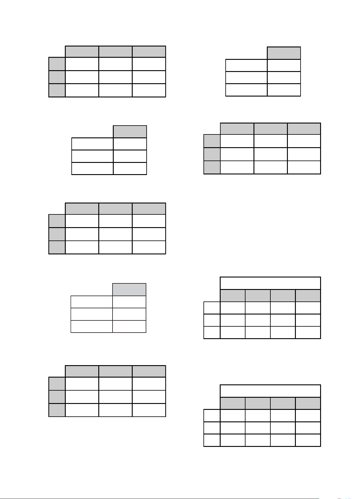
X Y To ler an ce
32"
40" 0.272 0.272 0.5JND
46" 0.273 0.274 0.5JND
0.27 0.271 0.5JND
7. Set up the correct values for 40IRE for TEST_R_LEVEL,
TEST_G_LEVEL and TEST_B_LEVEL.
40IRE
TEST_R_LEVEL 102
TEST_G_LEVEL 102
TEST_B_LEVEL 102
8. Adjust R_GAMMA_OFST_02 and B_GAMMA_OFST_02
chroma values so that they are within tolerance in the table below.
X Y Tole ra nce
32" 0.27 0.271 0.5JND
40"
46" 0.273 0.274 0.5JND
0.272 0.272 0.5JND
9. Set up the correct values for 60IRE for TEST_R_LEVEL,
TEST_G_LEVEL and TEST_B_LEVEL.
80IRE
TEST_R_LEVEL 204
TEST_G_LEVEL 204
TEST_B_LEVEL 204
12. Adjust R_GAMMA_OFST_04 and B_GAMMA_OFST_04
chroma values so that they are within tolerance in the table below.
X Y To ler an ce
32"
40" 0.272 0.272 0.5JND
46" 0.273 0.274 0.5JND
0.27 0.271 0.5JND
13. Write R_GAMMA_OFST_01~R_GAMMA_OFST_04 and
B_GAMMA_OFST_01~B_GAMMA_OFST_04 in the NVM.
14. Write R_GAMMA_OFST_04~R_GAMMA_OFST_05 and
B_GAMMA_OFST_04~B_GAMMA_OFST_05 in the NVM.
15. Set up TEST_PATTEN_ON=0.
16. Set up COL_MATRIX_INDEX=30.
17. Set up hreg_p1_d_p_26=3.
18. Set up hreg_p1_d_p_28=3.
19. Set up DYNAMIC_EN=0xffff
20. Set up COLOR_TEMP=1.
21. Write the correct values for R_DRV, B_DRV, R_BKG and B_BKG
from the table below.
ERI06
LEVEL_R_TSET351
LEVEL_G_TSET351
LEVEL_B_TSET351
10. Adjust R_GAMMA_OFST_03 and B_GAMMA_OFST_03
chroma values so that they are within tolerance in the table below.
X Y To ler an ce
32"
40" 0.272 0.272 0.5JND
46" 0.273 0.274 0.5JND
0.27 0.271 0.5JND
COLOR_TEMP=1 (NEUTRAL)
R_DRV B_DRV R_BKG B_BKG
32"
40"
46"
262 240 504 504
253 235 515 507
TBD TBD TBD TBD
22. Send ECS COLOR_SAVE command.
23. Set up COLOR_TEMP=2.
24. Write the correct values for R_DRV, B_DRV, R_BKG and B_BKG
from the table below.
COLOR_TEMP=2 (WARM1)
R_DRV B_DRV R_BKG B_BKG
32" 262 218 507 509
40"
46"
251 219 517 505
TBD TBD TBD TBD
- 28 -

25. Send ECS COLOR_SAVE command.
26. Set up COLOR_TEMP=3.
27. Write the correct values for R_DRV, B_DRV, R_BKG and B_BKG
from the table below.
COLOR_TEMP=3 (WARM2)
R_DRV B_DRV R_BKG B_BKG
32" 265 189 509 516
WAX2
RM-ED005
40"
46"
260 198 511 500
TBD TBD TBD TBD
28. Send ECS COLOR_SAVE command.
29. Switch the TV set OFF and then ON again to retain adjustment
values.
3-5. Panel Replacement
When replacing the panel please reset the gamma and white balance
before performing W/B (See page 27, 3-4) for new panel.
3-6. Board Replacement
3-6-1. AE Board Replacement
When replacing the ‘AE’ board please readjust the AD (See page 25,
3-2) and readjust the W/B (See page 27, 3-4).
3-6-2. BE Board Replacement
When replacing the ‘BE’ board please readjust the AD (See page 25,
3-2) and readjust the W/B (See page 27, 3-4).
Note :
In the event of a ‘BE’ board being re-used in service please
ensure that the Serial number is cleared in the NVM.
- 29 -
 Loading...