

Page 1

HISTORY INFORMATION FOR THE FOLLOWING MANUAL:
SERVICE MANUAL
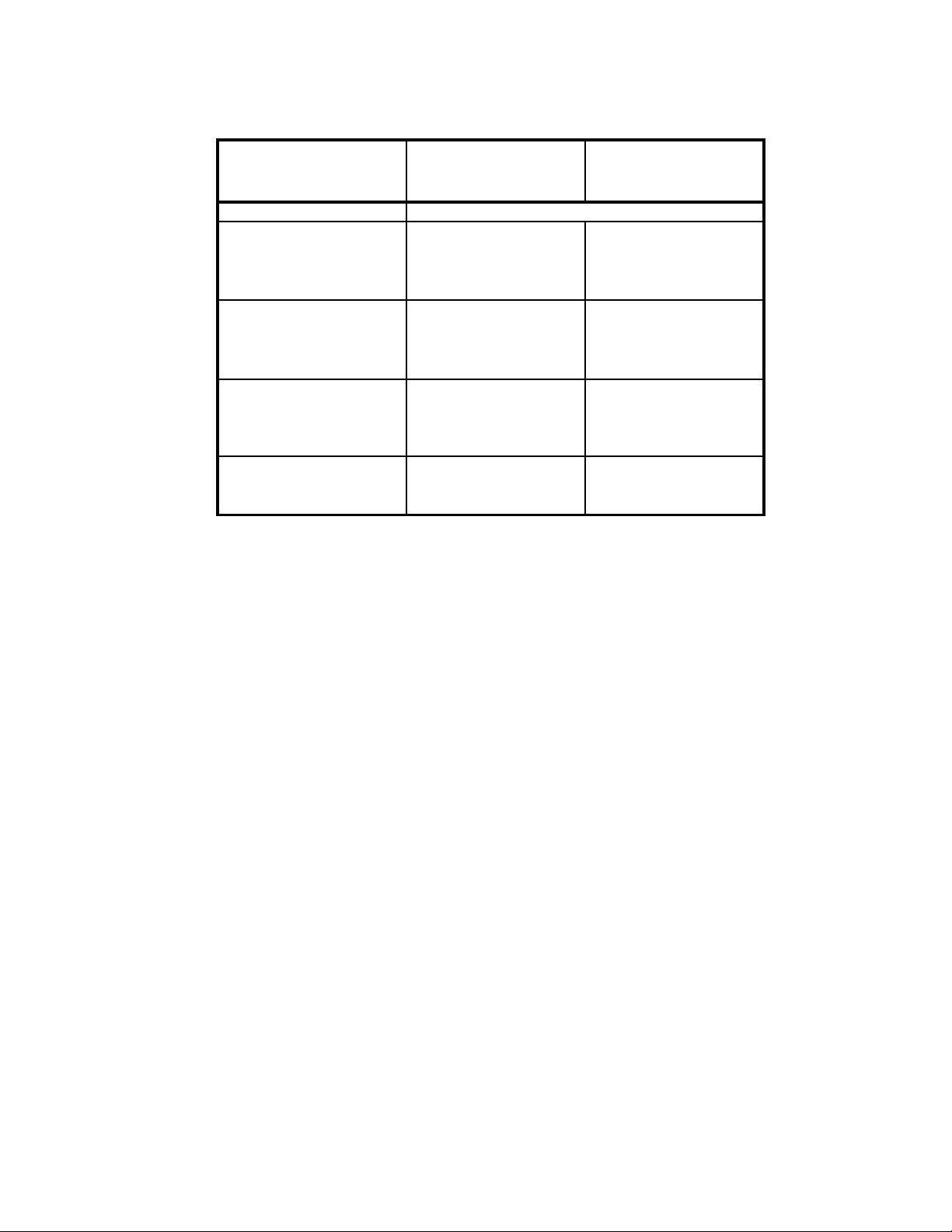
MODEL NAME REMOTE COMMANDER DESTINATION
KDL-32S20L1
KDL-40S20L1
RM-YD005 US
RM-YD005 US
WAX2
CHASSIS
ORIGINAL MANUAL ISSUE DATE: 5/2006
REVISION DATE SUBJECT
5/2006 No revisions or updates are applicable at this time.
9/2006 Updated entire manual to refl ect correct model name.
10/2006 Added correct part numbers for BU Boards. Replaced pages 54, 64, & 65.
Added Support Belt description to Lock Assy, Rudder. Replaced page 80.
1/2007 Added new Inverter Board PNs and LCD panel PNs for Serial Number range 4,200,001 to 4,299,999
and 8,200,001 to 8,299,999 (KDL-32S20L1 Only). Replaced page 56.
LCD DIGITAL COLOR TELEVISION
9-883-706-04
Page 2
Self Diagnosis
Supported model
SERVICE MANUAL
MODEL NAME REMOTE COMMANDER DESTINATION
KDL-32S20L1
KDL-40S20L1
RM-YD005 US
RM-YD005 US
WAX2
CHASSIS
9-883-706-04
KDL-32S20L1 RM-YD005
LCD DIGITAL COLOR TELEVISION
Page 3

KDL-32S20L1/40S20L1
TABLE OF CONTENTS
SECTION TITLE PAGE SECTION TITLE PAGE
Specifi cations ................................................................................. 4
Warnings and Cautions .................................................................. 6
Safety-Related Component Warning .............................................. 7
Safety Check-Out ........................................................................... 9
Self-Diagnostic Function ............................................................... 10
SECTION 1: DISASSEMBLY ............................................................... 12
1-1. Rear Cover Removal ............................................... 12
1-2. Vesa Bracket Assembly Removal ............................ 12
1-3. H1U Board Removal ................................................ 13
1-4. G1 Board (G2 Board) and H2U Board Removal ...... 13
1-5. AU Board Removal .................................................. 14
1-6. QT Board Removal .................................................. 14
1-7. QS board and BU Board Removal ........................... 15
1-8. H3U Board and Speaker Removal .......................... 15
1-9. LCD Panel Removal ................................................ 16
SECTION 2: SERVICE ADJUSTMENTS ............................................. 17
2-1. Remote Adjustment Buttons and Indicators ......................... 17
2-2. Accessing Service Adjustments ........................................... 17
2-2-1. Accessing the Digital Service Adjustment Menus .... 17
2-2-2. Viewing the Digital Module Box (Q-Box)
Service Items ........................................................... 18
2-2-3. Accessing the Analog Service Adjustment Menus ... 18
2-3. Resetting the User Menu - Factory Reset ............................ 19
2-4. Aging Mode .......................................................................... 19
2-5. White Balance Adjustment. .................................................. 20
SECTION 3: DIAGRAMS ..................................................................... 21
3-1. Circuit Boards Location ........................................................ 21
3-2. Printed Wiring Boards and
Schematic Diagrams Information ......................................... 21
3-3. Block Diagram ...................................................................... 23
3-4. Schematics and Supporting Information .............................. 24
AU Board Schematic Diagram (1 of 2) ................................. 24
AU Board Schematic Diagram (2 of 2) ................................. 25
BU Board Schematic Diagram (1 of 8) ................................. 27
BU Board Schematic Diagram (2 of 8) ................................. 28
BU Board Schematic Diagram (3 of 8) ................................. 29
BU Board Schematic Diagram (4 of 8) ................................. 30
BU Board Schematic Diagram (5 of 8) ................................. 31
BU Board Schematic Diagram (6 of 8) ................................. 32
BU Board Schematic Diagram (7 of 8) ................................. 33
BU Board Schematic Diagram (8 of 8) ................................. 34
G1 Board, Power Unit (KDL-32S20L1Only) ......................... 36
G2 Board Schematic Diagram (KDL-40S20L1 Only) ........... 38
H1U Board Schematic Diagram ........................................... 40
H2U Board Schematic Diagram ........................................... 41
H3U Board Schematic Diagram ........................................... 43
QS Board Schematic Diagram (1 of 5) ................................. 44
QS Board Schematic Diagram (2 of 5) ............................... 45
QS Board Schematic Diagram (3 of 5) ................................. 46
QS Board Schematic Diagram (4 of 5) ................................. 47
QS Board Schematic Diagram (5 of 5) ................................. 48
QT Board Schematic Diagram ............................................. 50
3-5. Semiconductors ................................................................... 52
SECTION 4: EXPLODED VIEWS ........................................................ 53
4-1. Rear Cabinet and Stand Assembly ..................................... 53
4-2. Chassis ............................................................................... 54
4-3. Speakers .............................................................................. 55
4-4. LCD Panel ............................................................................ 56
SECTION 5: ELECTRICAL PARTS LIST ............................................ 57
APPENDIX A: ENCRYPTION KEY COMPONENTS ..........................A-1
KDL-32S20L1/40S20L1
3
Page 4
SPECIFICATIONS
y
KDL-32S20L1/40S20L1
Power Requirements
Power Consumption (W)
In Use (Max)
In Standby
120V-240V AC, 50/60Hz
150W (KDL-32S20L1 Only)
200W (KDL-40S20L1 Only)
Less than 0.1W
Video (IN) 1/2/3
S Video (4-Pin Mini DIN (VIDEO 1/2 Only)
Y: 1.0 Vp-p, 75 ohms unbalanced, sync negative
C: 0.286 Vp-p (Burst signal), 75 ohms
Video
1.0 Vp-p, 75ohms unbalanced, sync negative
Audio
500 mVrms (100% modulation)
Impedance:47 kilohms
HD/DVD IN 4
YP
(Component Video)
BPR
Y:1.0 Vp-p, 75 ohms unbalanced, sync negative
PB:0.7 Vp-p, 75 ohms
PR:0.7 Vp-p, 75 ohms
Signal format: 480i, 480p, 720p, 1080i
AUDIO
500 mVrms (100% modulation)
Impedance: 47 kilohms
HDMI IN 6:
HDMI: Video:480i, 480p, 720p, 1080i
Audio: Two channel linear PCM 32, 44.1 and
48 kHz, 16, 20 and 24 bits
AUDIO: 500 mVrms (100% modulation)
Impedance: 47 kilohms
AUDIO OUT:
500 mVrms (100% modulation)
More than 1 Vrms at the maximum volume setting (Variable)
More than 500 mVrms (Fixed)
PC IN 7:
D-sub 15-pin, analog RGB, 0.7 Vp-p, 75 ohms, positive
PC AUDIO INPUT:
Stereo mini jack, 0.5 Vrms, 1 kilohm
Headphones:
Stereo mini jack
Impedance: 16 ohms
Speaker:
Full range: 4.2 × 15 cm (1
Full range: 5.5 × 15 cm (2
11/16
× 6 inches) (2) (KDL-32S20L1)
1/4
× 6 inches) (2) (KDL-40S20L1)
Trademark Information
TruSurround XT, SRS and ( ) symbol are trademarks of SRS Labs, Inc.
TruSurround XT technology is incorporated under license from SRS Labs ,
Inc.
Manufactured under license from BBE Sound, Inc.
Licensed by BBE Sound, Inc. under one or more of the following US
patents: 5510752, 5736897. BBE and BBE symbol are registered
trademarks of BBE Sound, Inc.
Macintosh is a trademark licensed to Apple Computer, Inc., registered in
the U.S.A and other countries.
“BRAVIA” and are trademarks of Sony Corporation.
As an ENERGY STAR
determined that this product meets the E NERGY STAR
guidelines for energy efficiency.
ENERGY STAR
HDMI, the HDMI logo and High-Definition Multimedia Interface are
trademarks or registered trademarks of HDMI Licensing, LLC.
Manufactured under license from Dolby
Laboratories. “Dolby” and the double-D symbol are
trademarks of Dolb
KDL-32S20L1/40S20L1
®
Partner, Sony Corporation has
®
is a U.S. registered mark.
This TV incorporates High-Definition
Multimedia Interface (HDMI™) technology.
Laboratories.
®
Design and specifi cations are subject to change without notice.
4
Page 5
KDL-32S20L1/40S20L1
Television system
American TV Standard
Channel coverage
VHF: 2-13/UHF: 14-69/ Cable TV: 1-125
Antenna
75-ohm external terminal for VHF/UHF
Panel System
LCD (Liquid Crystal Display) Panel
Supplied Accessories
Remote Commander RM-YD005
Two Size AA (R6) Batteries
75-ohm coaxial cable
AC Power Cord
HD15-HD15 Cable
Suport Belt, Securing Screw, and Wood Screw
Cable Holder
Operating Instructions
Quick Setup Guide
Warranty Card
KDL-32S20L1/40S20L1
Display Resolution (horizontal x vertical):
1,366 dots x 768 lines
Screen Size (measured diagonally)
32 inches (KDL-32S20L1 Only)
40 inches (KDL-40S20L1Only)
Optional Accessories
Headphones Plug Adaptor
Connecting Cables
Wall-Mount Bracket
SU-WL31 (KDL-32S20L1 Only)
SU-WL51 (KDL-40S20L1 Only)
5
Page 6

KDL-32S20L1/40S20L1
WARNINGS AND CAUTIONS
CAUTION
These servicing instructions are for use by qualifi ed service personnel only. To reduce the risk of electric shock, do not perform any
servicing other than that contained in the operating instructions unless you are qualifi ed to do so.
WARNING!!
An isolation transformer should be used during any service to avoid possible shock hazard, because of live chassis. The chassis of
this receiver is directly connected to the ac power line.
! SAFETY-RELATED COMPONENT WARNING!!
Components identifi ed by shading and ! mark on the schematic diagrams, exploded views, and in the parts list are critical for safe
operation. Replace these components with Sony parts whose part numbers appear as shown in this manual or in supplements
published by Sony. Circuit adjustments that are critical for safe operation are identifi ed in this manual. Follow these procedures
whenever critical components are replaced or improper operation is suspected.
ATTENTION!!
Ces instructions de service sont à l’usage du personnel de service qualifi é seulement. Pour prévenir le risque de choc électrique, ne
pas faire l’entretien autre que celui contenu dans le Mode d’emploi à moins que vous soyez qualifi é faire ainsi.
Afi n d’eviter tout risque d’electrocution provenant d’un chássis sous tension, un transformateur d’isolement doit etre utilisé lors de tout
dépannage. Le chássis de ce récepteur est directement raccordé à l’alimentation du secteur.
! ATTENTION AUX COMPOSANTS RELATIFS A LA SECURITE!!
Les composants identifi es par une trame et par une marque ! sur les schemas de principe, les vues explosees et les listes de pieces
sont d’une importance critique pour la securite du fonctionnement. Ne les remplacer que par des composants Sony dont le numero
de piece est indique dans le present manuel ou dans des supplements publies par Sony. Les reglages de circuit dont l’importance
est critique pour la securite du fonctionnement sont identifi es dans le present manuel. Suivre ces procedures lors de chaque
remplacement de composants critiques, ou lorsqu’un mauvais fonctionnement suspecte.
KDL-32S20L1/40S20L1
6
Page 7
KDL-32S20L1/40S20L1
SAFETY-RELATED COMPONENT WARNING
!
There are critical components used in LCD color TVs that are important for safety. These components are identifi ed with shading and
mark on the schematic diagrams and the electrical parts list. It is essential that these critical parts be replaced only with the part number
specifi ed in the electrical parts list to prevent electric shock, fi re, or other hazard.
NOTE: Do not modify the original design without obtaining written permission from the manufacturer or you will void the original parts and
labor guarantee.
USE CAUTION WHEN HANDLING THE LCD PANEL
When repairing the LCD panel, be sure you are grounded by using a wrist band.
When installing the LCD panel on a wall, the LCD panel must be secured using the 4 mounting holes on the rear cover.
To avoid damaging the LCD panel:
do not press on the panel or frame edge to avoid the risk of electric shock.
do not scratch or press on the panel with any sharp objects.
do not leave the module in high temperatures or in areas of high humidity for an extended period of time.
do not expose the LCD panel to direct sunlight.
avoid contact with water. It may cause a short circuit within the module.
disconnect the AC adapter when replacing the backlight (CCFL) or inverter circuit.
(High voltage occurs at the inverter circuit at 650Vrms.)
always clean the LCD panel with a soft cloth material.
use care when handling the wires or connectors of the inverter circuit. Damaging the wires may cause a short.
protect the panel from ESD to avoid damaging the electronic circuit (C-MOS).
LEAKAGE CURRENT HOT CHECK CIRCUIT
KDL-32S20L1/40S20L1
7
Page 8
The circuit boards used in these models have been processed using
Lead Free Solder. The boards are identified by the LF logo located
close to the board designation e.g. H1 etc [ see example ]. The
servicing of these boards requires special precautions to be taken as
outlined below.
KDL-32S20L1/40S20L1
example 1
It is strongly recommended to use Lead Free Solder material in order to guarantee optimal quality of new solder joints.
Lead Free Solder is available under the following part numbers :
rebmuntraP retemaiD skrameR
91-500-046-7mm3.0gK52.0
02-500-046-7mm4.0gK05.0
12-500-046-7mm5.0gK05.0
22-500-046-7mm6.0gK52.0
32-500-046-7mm8.0gK00.1
42-500-046-7mm0.1gK00.1
52-500-046-7mm2.1gK00.1
62-500-046-7mm6.1gK00.1
Due to the higher melting point of Lead Free Solder the soldering iron tip temperature needs to be set to 370 degrees centigrade.
This requires soldering equipment capable of accurate temperature control coupled with a good heat recovery characteristics.
For more information on the use of Lead Free Solder, please refer to
http://www.sony-training.com
KDL-32S20L1/40S20L1
8
Page 9
SAFETY CHECK-OUT
KDL-32S20L1/40S20L1
After correcting the original service problem, perform the following
safety checks before releasing the set to the customer:
1. Check the area of your repair for unsoldered or poorly soldered
connections. Check the entire board surface for solder splashes and
bridges.
2. Check the interboard wiring to ensure that no wires are “pinched” or
touching high-wattage resistors.
3. Check that all control knobs, shields, covers, ground straps, and
mounting hardware have been replaced. Be absolutely certain that
you have replaced all the insulators.
4. Look for unauthorized replacement parts, particularly transistors,
that were installed during a previous repair. Point them out to the
customer and recommend their replacement.
5. Look for parts which, though functioning, show obvious signs of
deterioration. Point them out to the customer and recommend their
replacement.
6. Check the line cords for cracks and abrasion. Recommend the
replacement of any such line cord to the customer.
7. Check the antenna terminals, metal trim, “metallized” knobs, screws,
and all other exposed metal parts for AC leakage. Check leakage as
described below.
The AC leakage from any exposed metal part to earth ground and
from all exposed metal parts to any exposed metal part having a
return to chassis, must not exceed 0.5 mA (500 microamperes).
Leakage current can be measured by any one of three methods.
1. A commercial leakage tester, such as the Simpson 229 or RCA
WT-540A. Follow the manufacturers’ instructions to use these
instructions.
2. A battery-operated AC milliampmeter. The Data Precision 245
digital multimeter is suitable for this job.
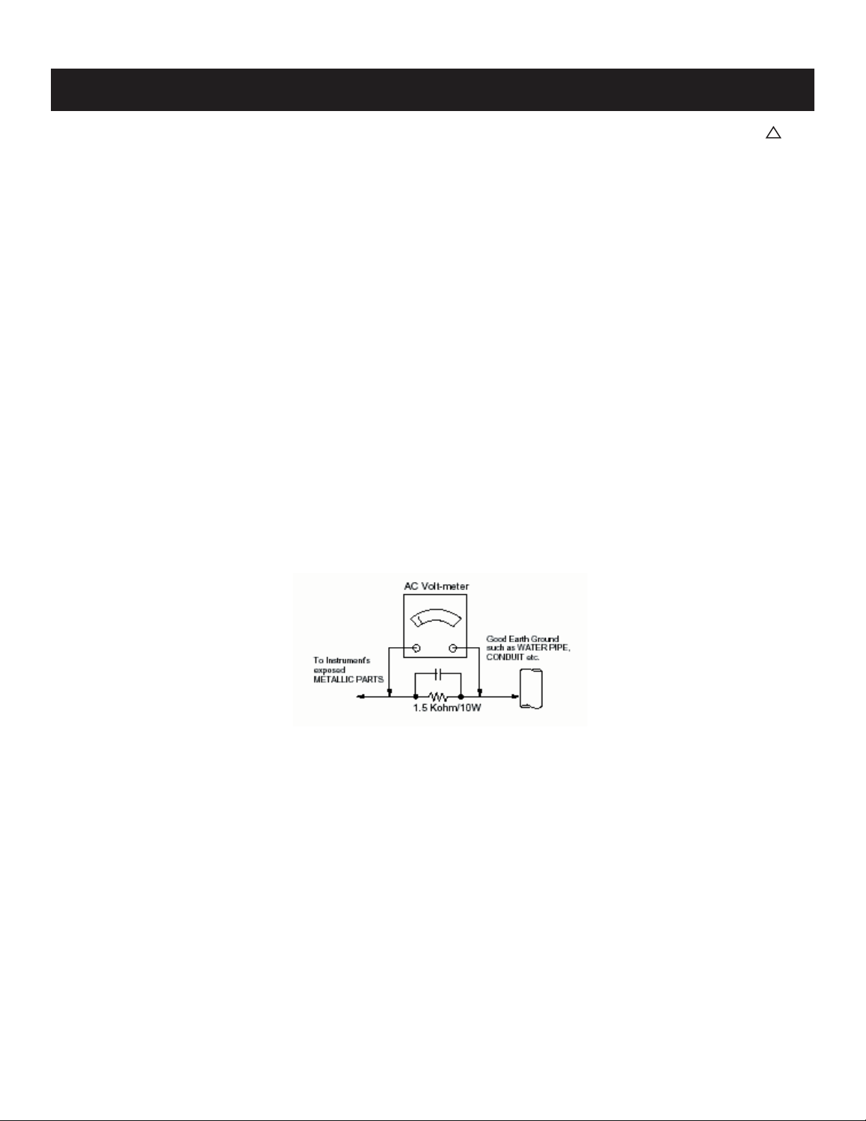
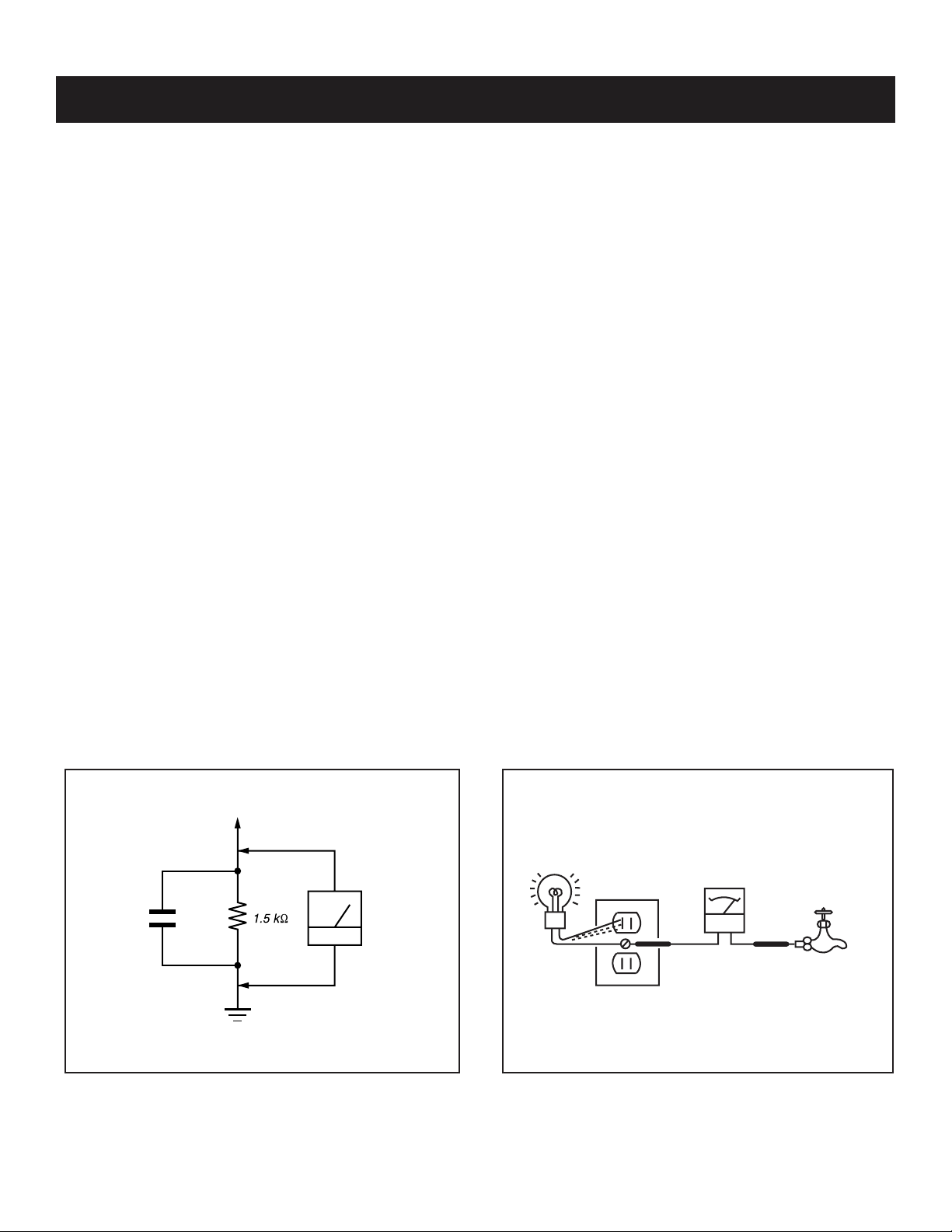
3. Measuring the voltage drop across a resistor by means of a VOM
or battery-operated AC voltmeter. The “limit” indication is 0.75
V, so analog meters must have an accurate low voltage scale.
The Simpson’s 250 and Sanwa SH-63TRD are examples of
passive VOMs that are suitable. Nearly all battery-operated digital
multimeters that have a 2 VAC range are suitable (see Figure A).
How to Find a Good Earth Ground
A cold-water pipe is a guaranteed earth ground; the cover-plate
retaining screw on most AC outlet boxes is also at earth ground. If the
retaining screw is to be used as your earth ground, verify that it is at
ground by measuring the resistance between it and a cold-water pipe
with an ohmmeter. The reading should be zero ohms.
If a cold-water pipe is not accessible, connect a 60- to 100-watt
trouble- light (not a neon lamp) between the hot side of the receptacle
and the retaining screw. Try both slots, if necessary, to locate the hot
side on the line; the lamp should light at normal brilliance if the screw
is at ground potential (see Figure B).
Leakage Test
0.15 µF
Figure A. Using an AC voltmeter to check AC leakage. Figure B. Checking for earth ground.
To Exposed Metal
Parts on Set
Earth Ground
AC
Voltmeter
(0.75V)
Trouble Light
AC Outlet Box
Ohmmeter
Cold-water Pipe
KDL-32S20L1/40S20L1
9
Page 10
KDL-32S20L1/40S20L1
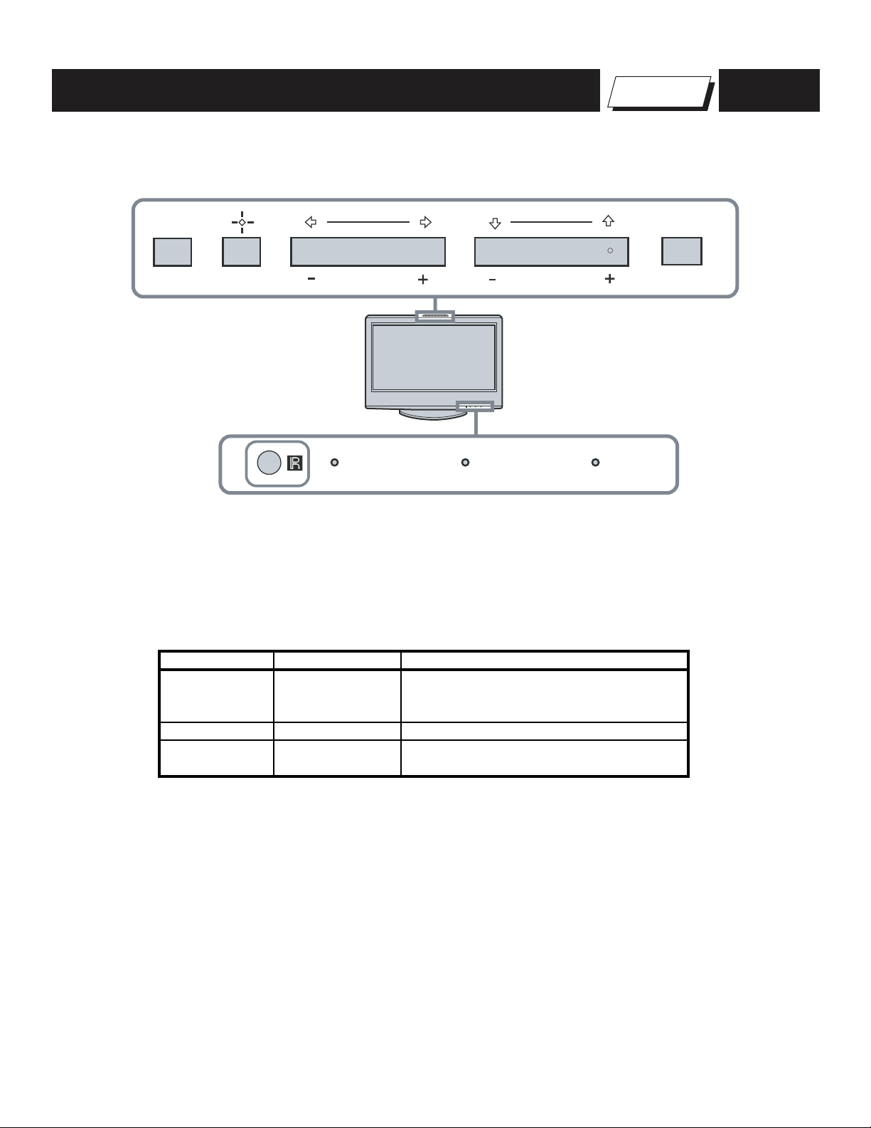
Control Buttons
MENU
TV/VIDEO
SELF-DIAGNOSTIC FUNCTION
VOLUME
PIC OFF/TIMER STANDBY POWER
CHANNEL
Self Diagnosis
Supported model
POWER
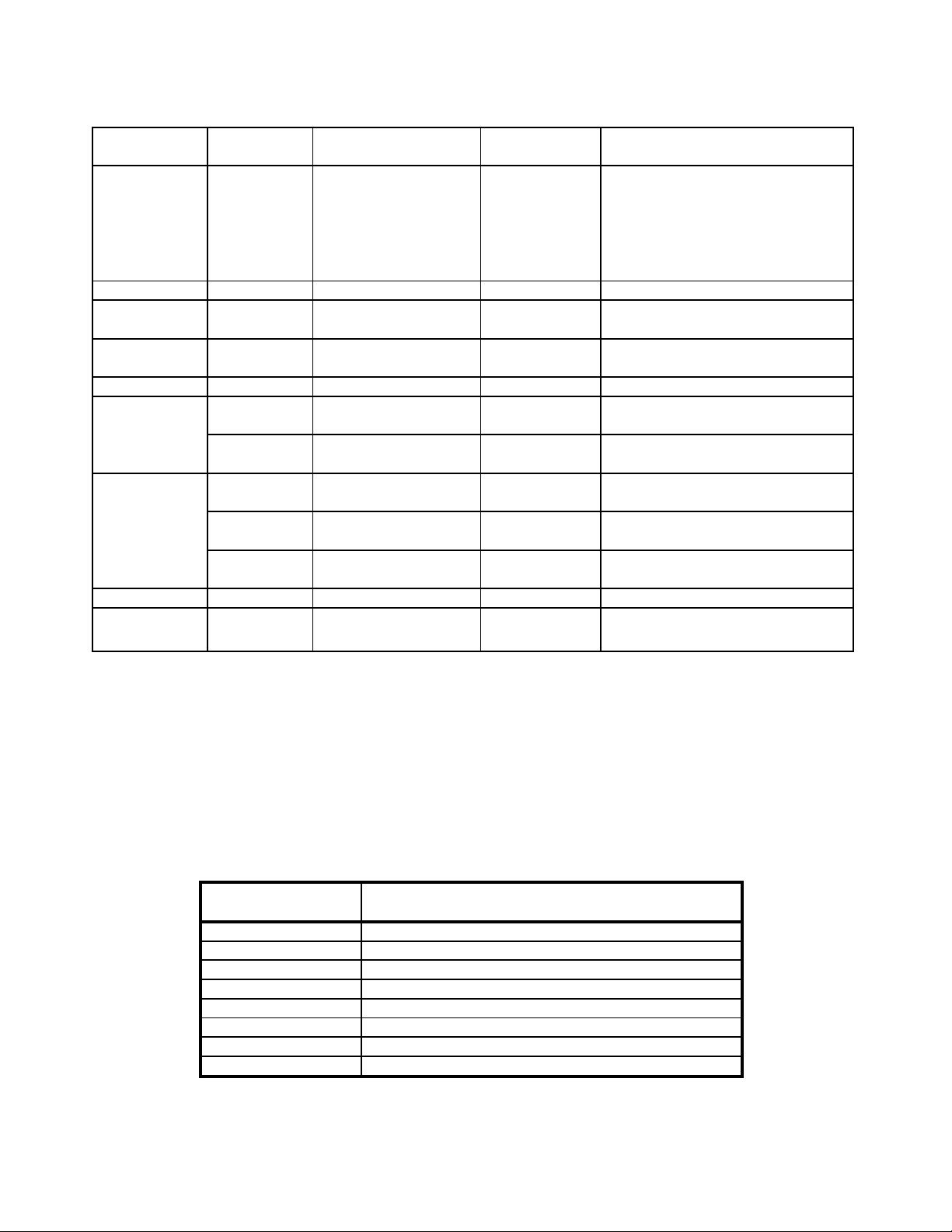
Description of LED Indictors
LED LED Type Description
POWER LED Red/Green LED
TIMER LED Red LED Lights when timer is set
PIC OFF LED Green LED
* Light is green when the TV set is on
* Functions as failure indicator
* Blinks green in aging mode
Lights when power saving setting is set to
picture off (See Instruction Manual)
KDL-32S20L1/40S20L1
10
Page 11
LED Control
KDL-32S20L1/40S20L1
The units in this manual contain a self-diagnostic function. If an error occurs, the POWER LED will automatically begin to fl ash. The number of times
the LED fl ashes translates to a probable source of the problem. A defi nition of the POWER LED fl ash indicators is listed in the instruction manual for
the user’s knowledge and reference. If an error symptom is diffi cult to reproduced use the Remote Commander to display the record that is stored at
the internal NVM to specify the cause of the failure.
Diagnostic Test Indicators
When an error occurs, the POWER LED will fl ash a set number of times to indicate the possible cause of the problem. If there is more than one error,
the LED will identify the fi rst of the problem areas. If the errors occur simultaneously, the one that corresponds to the fewest fl ashes is identifi ed fi rst.
Results for all of the following diagnostic items are displayed on screen. No error has occurred if the screen displays a “0”.
KDL-32S20L1/40S20L1
11
Page 12
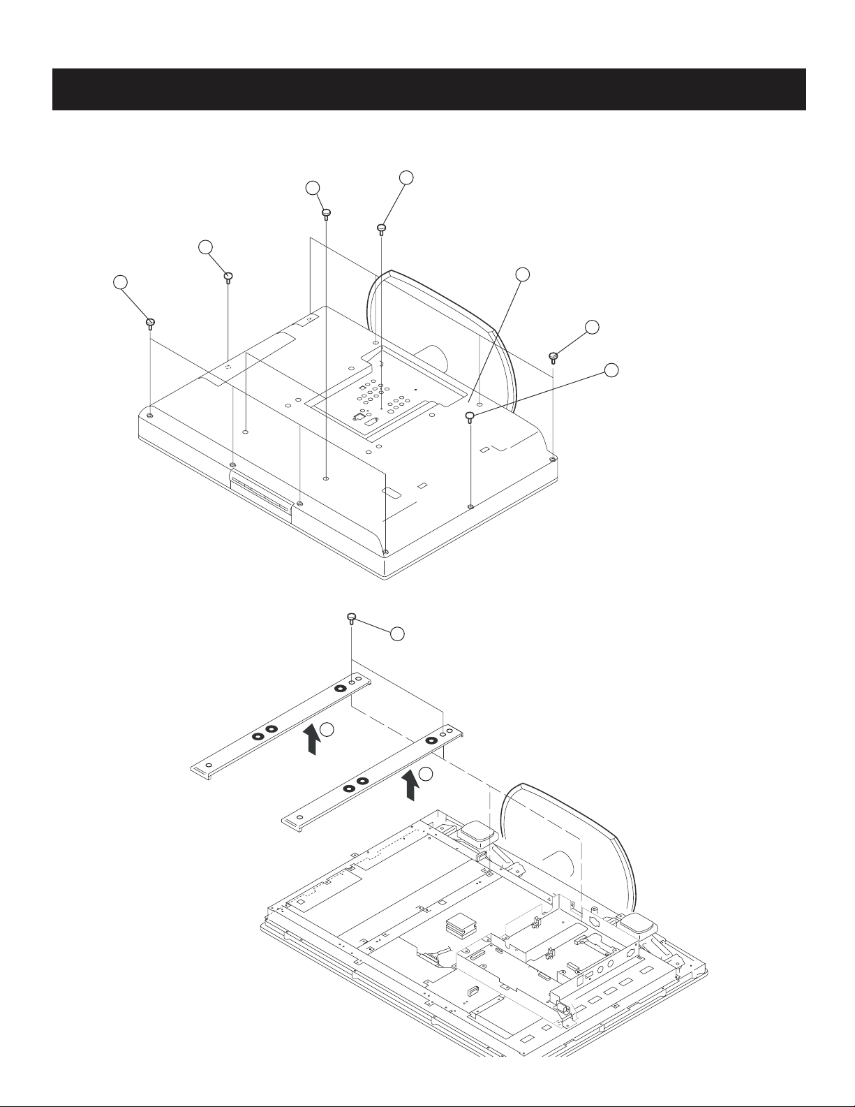
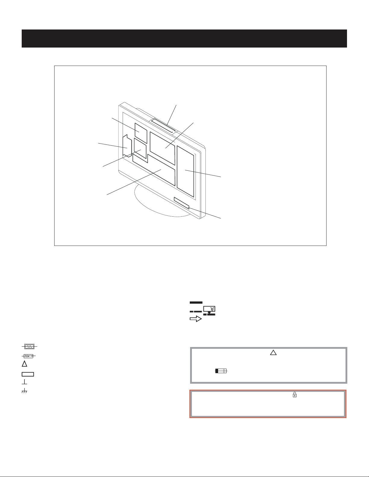
1-1. REAR COVER REMOVAL
2 Screws
+BVTP 3X12 TYPE2 IT-3
1 Screw, +BVTP2 4X16
2
4 Screws
1
+BVTP2 4X16
SECTION 1: DISASSEMBLY
4
3
2 Screws, +PSW M6X16
7
Lift to remove Rear Cover
4 Screws
5
+BVTP2 4X16
6
1 Screw, +BVTP2 4X16
KDL-32S20L1/40S20L1
1-2. VESA BRACKET ASSEMBLY REMOVAL
1
2
2 Screws, +PSW M4X16
(KDL-32S20L1 ONLY)
4 Screws, +PSW M5X16
(KDL-40S20L1 ONLY)
2
KDL-32S20L1/40S20L1
12
Page 13
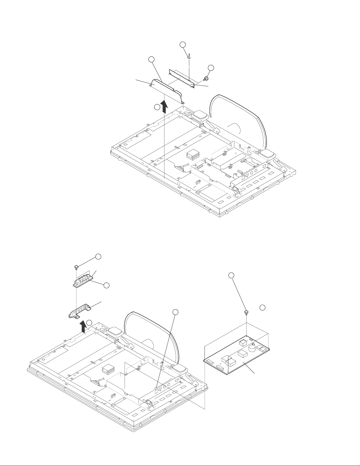
1-3. H1U BOARD REMOVAL
Disconnect CN101
1
KDL-32S20L1/40S20L1
Pull tabs on bracket to release board
Multi Button Assy
4
2 Screws +BVTP2 4X12
3
H1U Board
2
1-4. G1 BOARD (G2 BOARD) AND H2U BOARD REMOVAL
3
2 Screws
+BVTP 3X12 TYPE2 IT-3
H2U Board
1 Connector CN201
1
Side Jack Holder
Pull tabs back on
3
bracket to release.
2
2 Screws +BVTP 3X12 TYPE2 IT-3
2
(KDL-32S20L1 ONLY)
4 Screws +PSW 3SG
(KDL-40S20L1 ONLY)
3 Connectors CN6102, CN6202,
1
and CN6203 (G1 Board only)
3 Connectors CN6001, CN6200,
and CN6202 (G2 Board only)
G1 Board
(KDL-32S20L1 Only)
G2 Board
(KDL-40S20L1 Only)
KDL-32S20L1/40S20L1
13
Page 14
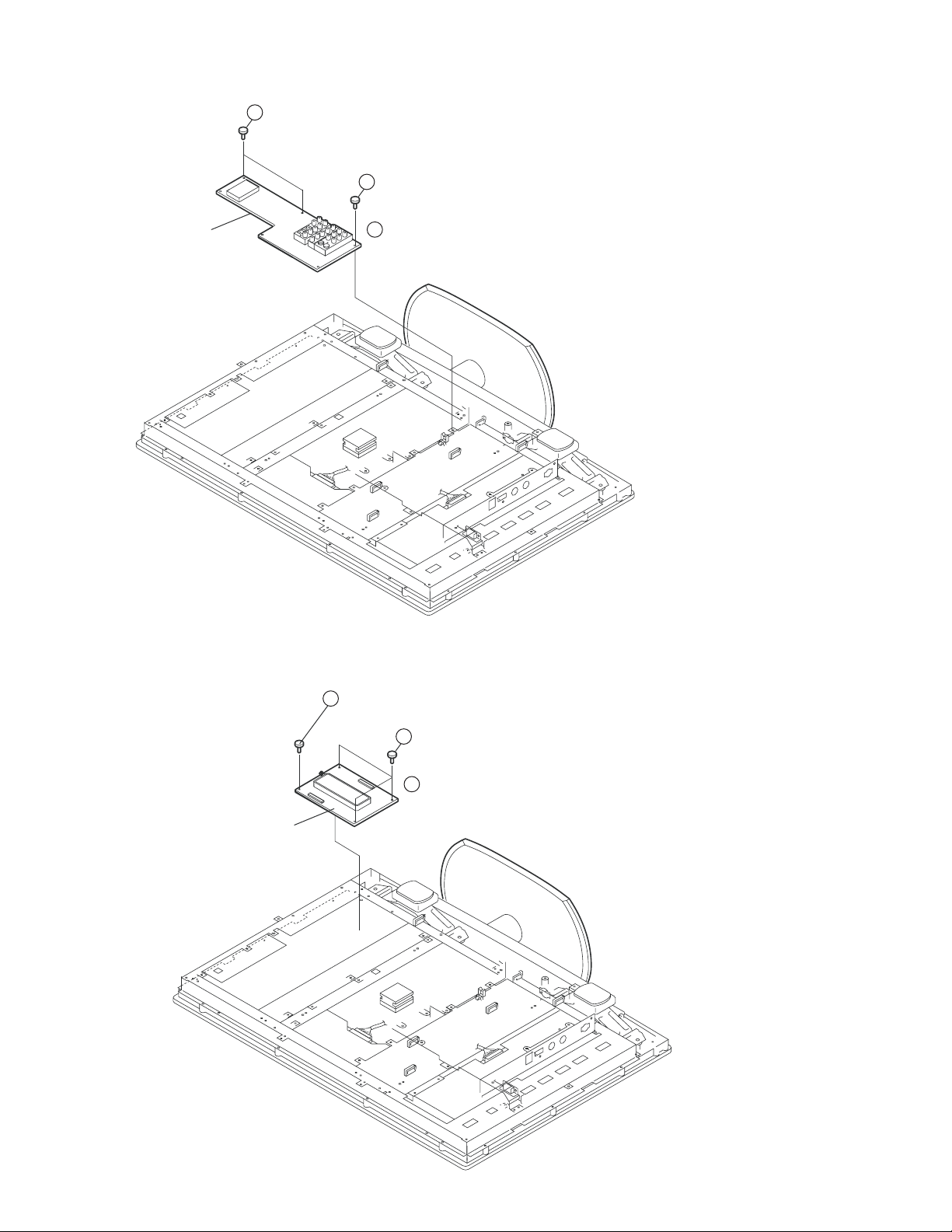
1-5. AU BOARD REMOVAL
3
2 Screws +BVTP 3X12 TYPE2 IT-3
AU board
2
4 Screws +PSW 3SG
7 Connectors CN9502, CN9501, CN7502, CN7501, CN9001, CN7503, CN7000
1
KDL-32S20L1/40S20L1
1-6. QT BOARD REMOVAL
QT board
1 Screws +PSW 3SG
3
2
3 Screws +BVTP 3X12 TYPE2 IT-3
1
2 Connectors CN7803 and CN7800
KDL-32S20L1/40S20L1
14
Page 15
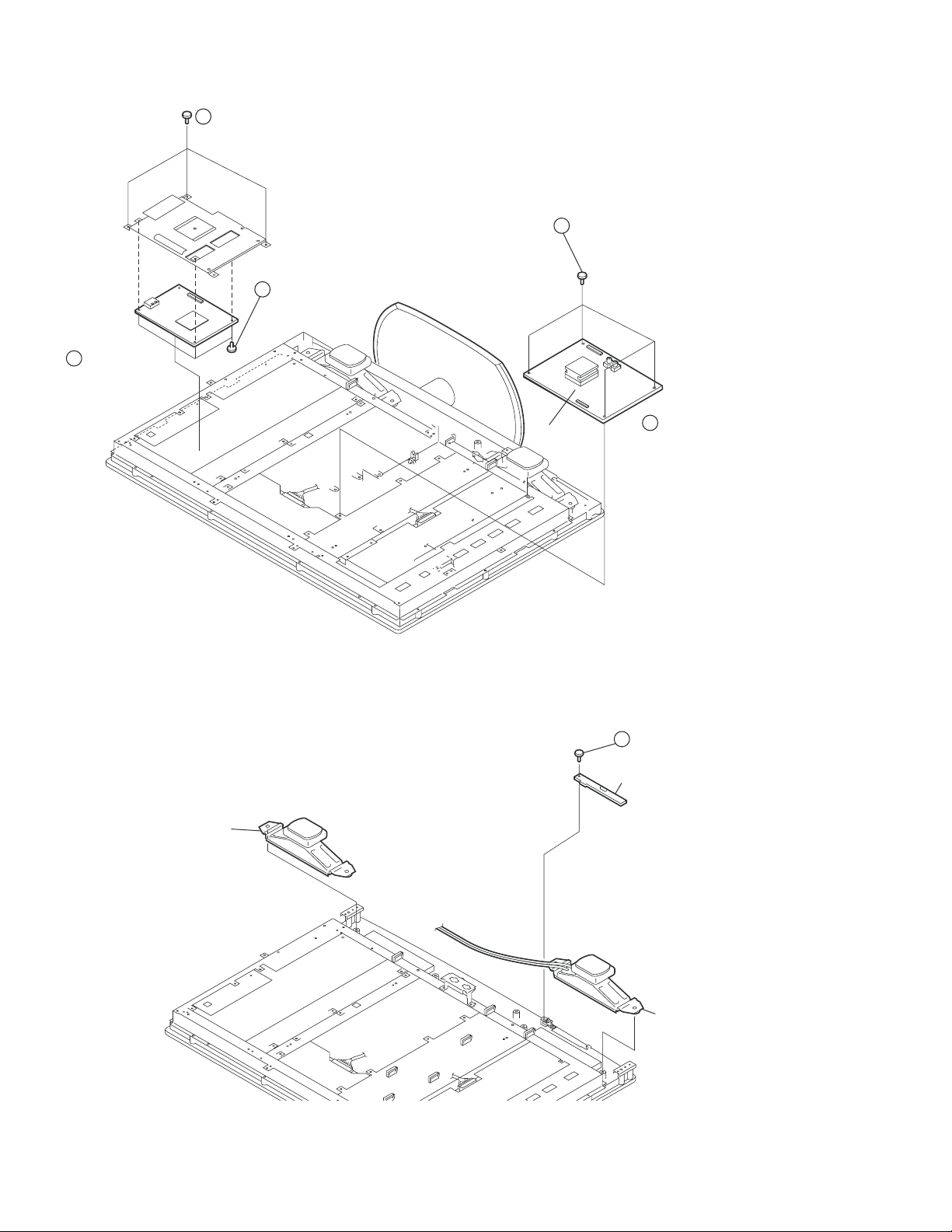
1-7. QS BOARD AND BU BOARD REMOVAL
2
3 Screws +PSW 3SG
3
3 Screws, +PSW M3X5
4 Connectors
1
CN7306, CN7314
CN7317, CN7802
2 Screws +PSW 3SG
2
BU board
KDL-32S20L1/40S20L1
1
10 Connectors
CN1007, CN7009, CN1002, CN4701,
CN4702, CN1700, CN5000,
CN1001, CN7008, CN1008
NOTE: CN1004 & CN1003 are not used.
1-8. H3U BOARD AND SPEAKER REMOVAL
Speaker
1
One screw
(+BVTP 3X10)
H3U Board
Speaker
KDL-32S20L1/40S20L1
15
Page 16
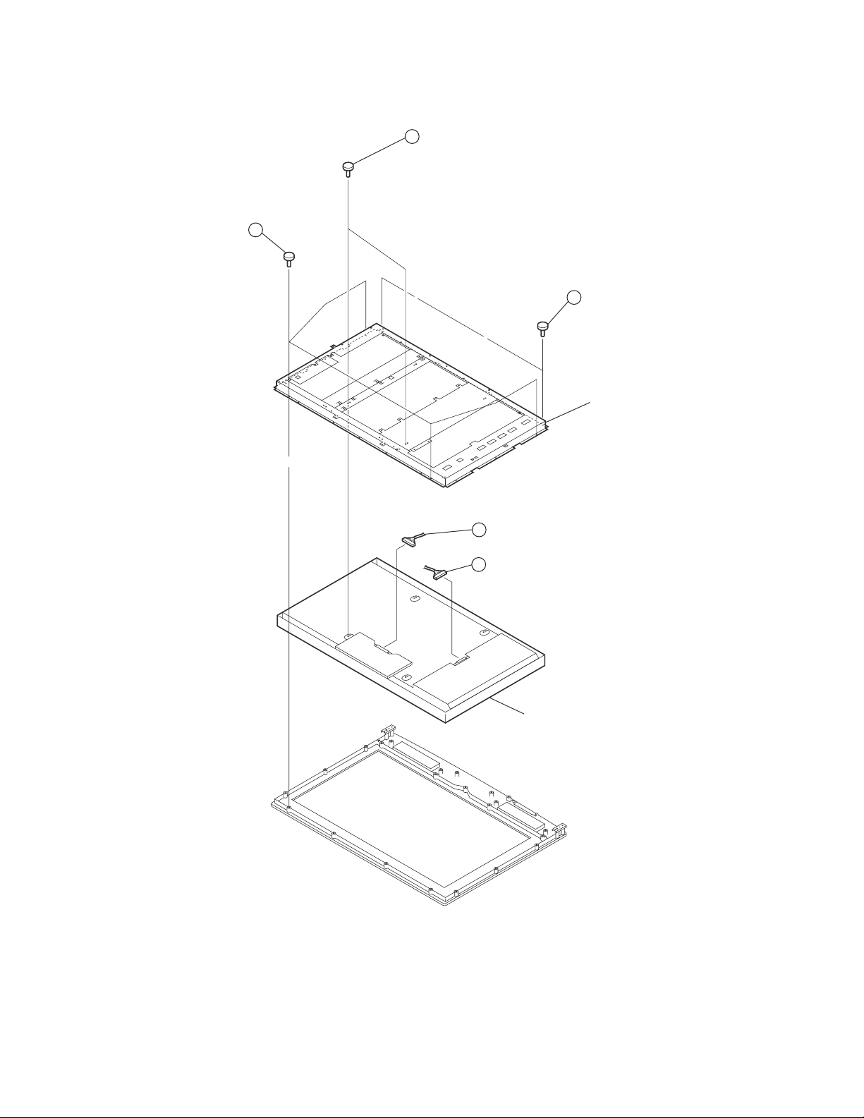
1-9. LCD PANEL REMOVAL
2 Screws, +PSW M4X8
1
(KDL-32S20L1 ONLY)
2 Screws, +PSW M5X8
(KDL-40S20L1 ONLY)
KDL-32S20L1/40S20L1
4 Screws,
2
+BVTP2 4X16
3
2 Screws, +PSW M4X8
(KDL-32S20L1 ONLY)
2 Screws, +PSW M5X8
(KDL-40S20L1 ONLY)
LCD bracket assy
Harness with connector (LVDS)
4
Connecter assy 14P
5
KDL-32S20L1/40S20L1
LCD panel
16
Page 17
SECTION 2: SERVICE ADJUSTMENTS
KDL-32S20L1/40S20L1
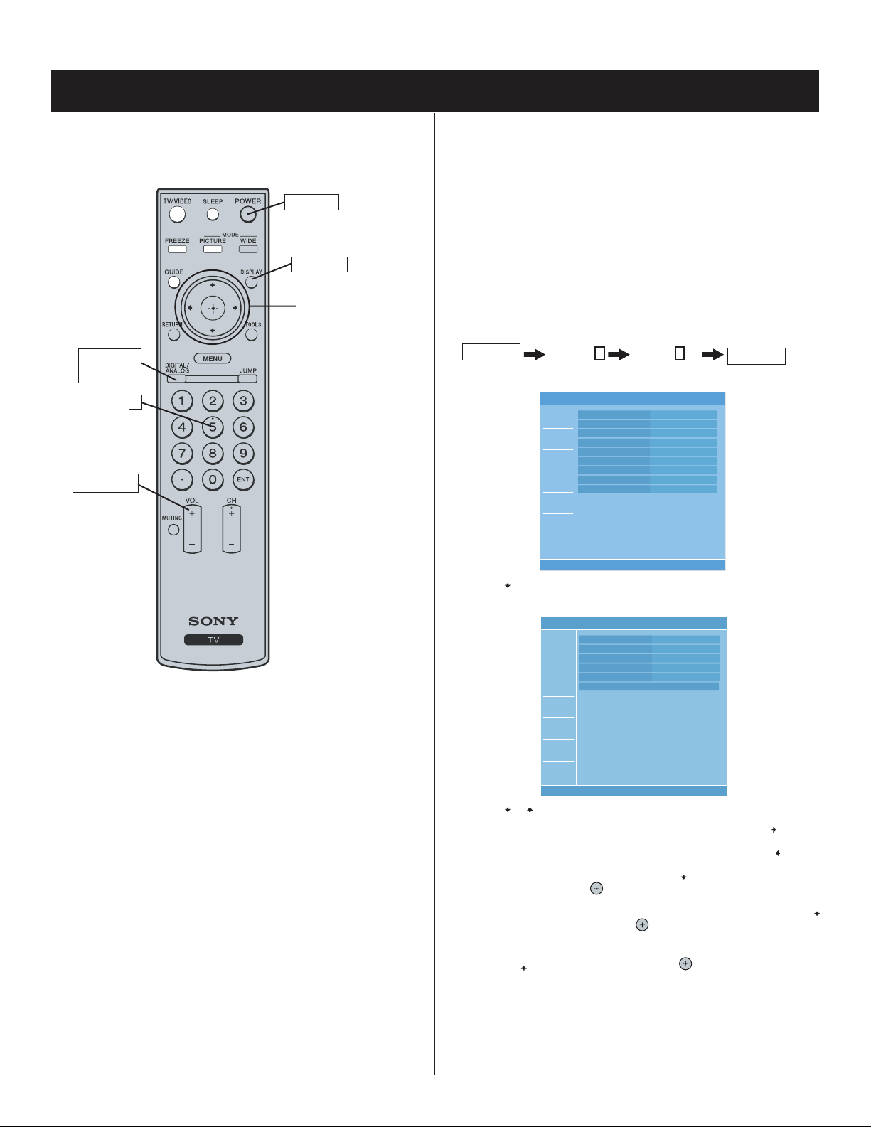
2-1. REMOTE ADJUSTMENT BUTTONS AND
INDICATORS
POWER
DISPLAY
Onscreen cursor
and select button
DIGITAL/
ANALOG
5
VOLUME+
2-2. ACCESSING SERVICE ADJUSTMENTS
To adjust various set features, use the Remote Commander to put the set
into service mode to display the service menus. The Remote Commander
displays the service menu associated with the Digital or Analog format
depending on which format is on the TV when you enter service mode.
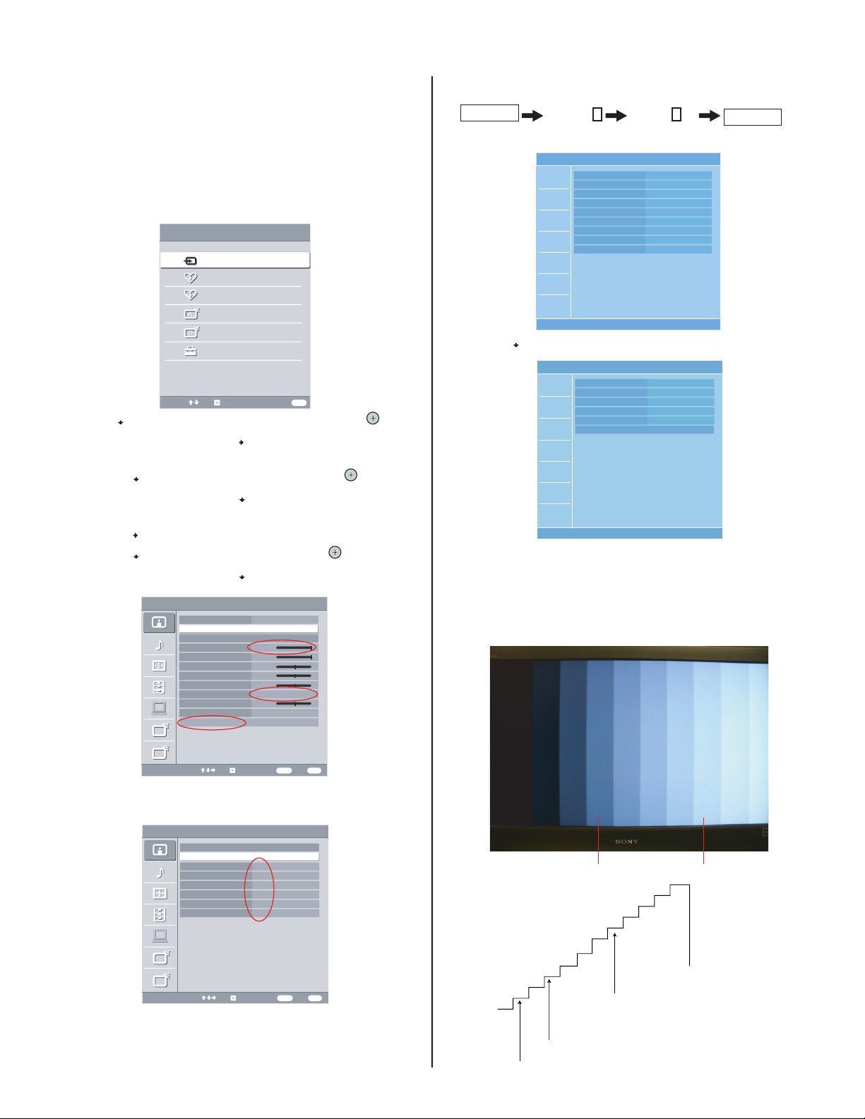
2-2-1. ACCESSING THE DIGITAL SERVICE
ADJUSTMENT MENUS
1. Turn the TV on and view a Digital channel.
2. Put the TV in standby mode. (Power off).
3. Press the following buttons on the Remote Commander within a
second:
DISPLAY
Channel
The Digital service menu displays.
5
Volume +
MAIN VER. 1009
H PACK VER. 1008
S PACK VER. 1008
CHECK SUM E20E
NVM VER. 1006
ATI VER. 01.06
ATI UD NVM VER. 02
ATI SD NVM VER. 02
ETI 46h 39m
Video 1
POWER
On.
4. Use the button to view the next category listing the white balance
adjustment items.
Video 1
R_DRIVE 256
RM-YDOO5
RM-YD005
B_DRIVE 256
R_BKG 512
G_BKG 512
B_BKG 512
COLOR SAVE
5. Use the or button to select the item you want to adjust.
a. To increase the data value of the category, press the
b. To decrease the data value of the category, press the
6. To save the data value changes, press the
Save and then press the
button.
button to select Color
a. To save the data value changes, select Save by pressing the
button and then press the
button.
button.
button.
b. To cancel the data value changes, select Cancel by pressing
the
button and then pressing the button.
KDL-32S20L1/40S20L1
17
Page 18
KDL-32S20L1/40S20L1
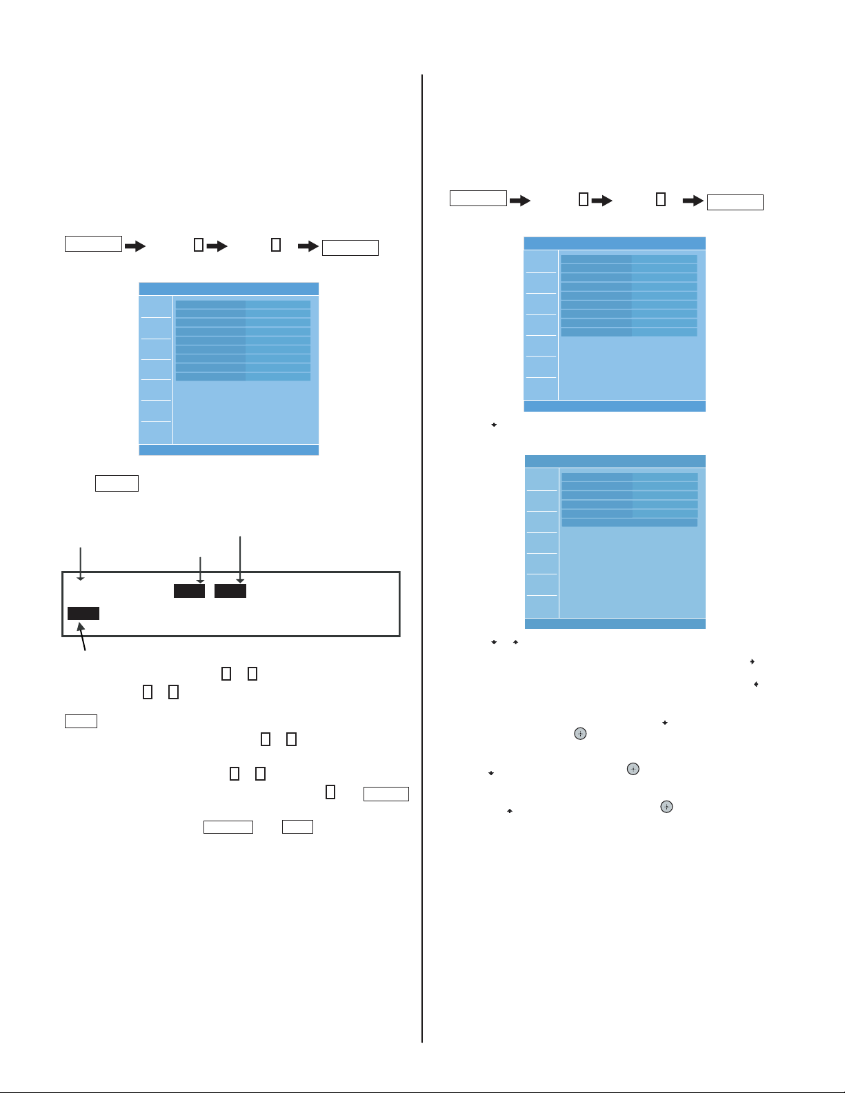
2-2-2. VIEWING THE DIGITAL MODULE BOX
2-2-3. ACCESSING THE ANALOG SERVICE
(Q-BOX) SERVICE ITEMS
Use the following instructions to display the Digital menu items you want
to adjust.
1. Turn the TV on and view a Digital channel.
2. Put the TV in standby mode. (Power off).
3. Press the following buttons on the Remote Commander within a
second:
DISPLAY
Channel
5
Volume +
POWER
On.
The Digital service menu displays.
Video 1
MAIN VER. 1009
H PACK VER. 1008
S PACK VER. 1008
CHECK SUM E20E
NVM VER. 1006
ATI VER. 01.06
ATI UD NVM VER. 02
ATI SD NVM VER. 02
ETI 46h 39m
4. To display the Digital Module (Q Box) service adjustment menus,
JUMP
press
.
The QM category displays.
Category
Data Value
Item #
1. Turn the TV on and view an Analog channel.
2. Put the TV in standby mode. (Power off).
3. Press the following buttons on the Remote Commander within a
The Analog service menu displays.
4. Use the button to view the next category listing the white balance
ADJUSTMENT MENUS
second:
DISPLAY
Channel
adjustment items.
5
MAIN VER. 1008
H PACK VER. 1005
S PACK VER. 1008
CHECK SUM F99F
NVM VER. 1006
ATI VER.
ATI UD NVM VER.
ATI SD NVM VER. 02
ETI 2h 16m
R_DRIVE 256
B_DRIVE 256
R_BKG 512
G_BKG 512
B_BKG 512
COLOR SAVE
Volume +
Video 1
Video 1
POWER
On.
QM
0
0
SERVICE
DTVINFO
Item
Sample DMB (Q Box) Service Menu
5. To change the category, press 2 or 5 on the Remote Commander.
Note: Pressing 2 or 5 only changes the categories within the service
menu displayed. To return to the Digital Service Menu, press the
JUMP
button.
6. To change the adjustment item, press 1 or 4 on the Remote
Commander.
7. To change the data value, press 3 or 6 on the Remote Commander.
Note: To go back to the last saved data value, press 0 then
ENTER
on the Remote Commander to read the memory.
8. To write into memory, press
MUTING
then
ENT
on the Remote
Commander.
9. To exit service mode, turn the power off.
5. Use the or button to select the item you want to adjust.
a. To increase the data value of the category, press the
b. To decrease the data value of the category, press the
button.
button.
6. To save the data value changes, press the
Save and then press the
button.
button to select Color
a. To save the data value changes, select Save by pressing the
button and then press the button.
b. To cancel the data value changes, select Cancel by pressing
the
button and then pressing the button.
KDL-32S20L1/40S20L1
18
Page 19
KDL-32S20L1/40S20L1
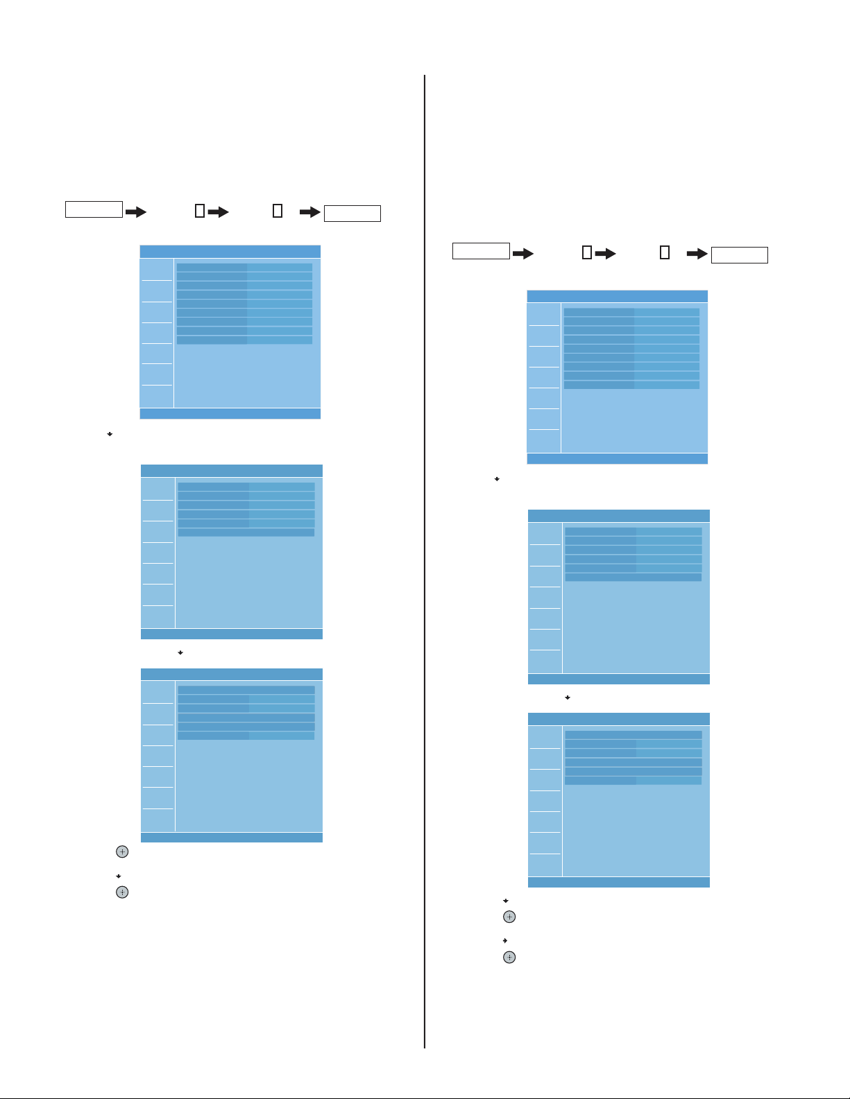
2-3. RESETTING THE USER MENU - FACTORY
RESET
The TEST RESET option resets all the customer adjustable data back to the
factory defaults.
1. Put the TV in standby mode. (Power off).
2. Press the following buttons on the Remote Commander within a second:
DISPLAY
Channel
The service menu displays.
5
Volume +
MAIN VER. 1009
H PACK VER. 1008
S PACK VER. 1008
CHECK SUM E20E
NVM VER. 1006
ATI VER. 01.06
ATI UD NVM VER. 02
ATI SD NVM VER. 02
ETI 46h 39m
Video 1
POWER
On.
2-4. AGING MODE
Aging mode is designed to remove image retention from the screen.
NOTE: Once you enter into Aging Mode the Remote Commander no
longer functions with the set. To turn off the set, push the Power Button
on the set.
1. Put the TV in standby mode. (Power off).
2. Press the following buttons on the Remote Commander within a
second:
DISPLAY
The service menu displays.
3. Use the button to view the next category listing the white balance
adjustment items.
R_DRIVE 256
B_DRIVE 256
R_BKG 512
G_BKG 512
B_BKG 512
COLOR SAVE
Video 1
3. Use the button to view the next category listing the white balance
adjustment items.
Channel
5
Volume +
MAIN VER. 1009
H PACK VER. 1008
S PACK VER. 1008
CHECK SUM E20E
NVM VER. 1006
ATI VER. 01.06
ATI UD NVM VER. 02
ATI SD NVM VER. 02
ETI 46h 39m
R_DRIVE 256
B_DRIVE 256
R_BKG 512
G_BKG 512
B_BKG 512
COLOR SAVE
Video 1
Video 1
POWER
On.
4. Continue pressing the button until the next category list displays.
Video 1
TEST RESET
AGING MODE Off
AUTO SHUT-OFF On
ETI CLEAR
INFORMATION RESET
SOUND MUTE On
5. Press the button to select TEST RESET options.
6. Press the
7. Press the
button to select OK.
button to reset the TV.
4. Continue pressing the button until the next category list displays.
Video 1
TEST RESET
AGING MODE Off
AUTO SHUT-OFF On
ETI CLEAR
INFORMATION RESET
SOUND MUTE On
5. Press the button to select AGING MODE.
6. Press the
7. Press the
8. Press the
button to display the Aging Mode options.
button to select ON.
button to start the aging process.
KDL-32S20L1/40S20L1
19
Page 20
KDL-32S20L1/40S20L1
2-5. WHITE BALANCE ADJUSTMENT
.
The White Balance only needs to be adjusted when you replace the BU
Board.
1. Through the Video 1 input, step Gray Scale with Setup.
2. Press MENU on the Remote Commander.
The User Menu displays.
MENU
External Inputs
Analog Favorites
Digital Favorites
Analog
Digital
Settings
Select from connected equipment
Select:
MENU
Exit:Set:
3. Press the button until Settings is selected, then press the button.
4. From the Picture menu, press the
button to display the picture mode
options.
a. Press the
5. From the Picture menu, press the
button to select Custom, then press the button.
button to select Color
Temperature.
a. Press the
b. Press the
6. From the Picture menu, press the
Settings.
button to display the Color Temperature options.
button to select Cool, then press the button.
button to select Advanced
Picture Video 1
Target Inputs All Inputs
Picture Mode Custom
Reset
Backlight Max
Picture Max
Brightness 50
Color 50
Hue 0
Color Temperature Cool
Sharpness 15
Noise Reduction Low
Advanced Settings
A
A
D
D
MENU
Select:
RETURN
Back: Exit:Set:
7. Using the arrow keys set all the registers in the Advanced Setting
menu to Off.
9. Access the Service Menu by pressing the following buttons on the
Remote Commander within a second:
DISPLAY
Channel
5
Volume +
POWER
On.
The Digital service menu displays.
Video 1
MAIN VER. 1009
H PACK VER. 1008
S PACK VER. 1008
CHECK SUM E20E
NVM VER. 1006
ATI VER. 01.06
ATI UD NVM VER. 02
ATI SD NVM VER. 02
ETI 46h 39m
10. Press the button to display the white balance adjustment menu
items.
R_DRIVE 256
B_DRIVE 256
R_BKG 512
G_BKG 512
B_BKG 512
COLOR SAVE
Video 1
11. Using 10 step NTSC Gray Scale with Setup adjust the White Balance
of the 60% shade with R_Drive and B_Drive.
12. Using the same pattern, adjust the white balance 20% with R_BKG
and B_BKG.
13. 20IRE and 60IRE shades should have the same color.
Picture Video 1
Advanced Settings
Reset
Black Corrector Off
Contrast Enhancer Off
Gamma Off
Clear White Off
Live Color Off
MPEG Noise Reduction Off
A
A
D
D
Select:
Back: Exit:Set:
8. Put the TV in standby mode. (Power off).
KDL-32S20L1/40S20L1
RETURN
MENU
SET-UP
56mv
20%
188mv
20 IRE Level
60%
451mv
60 IRE Level
10 STEP
GRAY SCALE
20
Page 21
3-1. CIRCUIT BOARDS LOCATION
KDL-32S20L1/40S20L1
SECTION 3: DIAGRAMS
H1U Board
QS Board
H2U Board
QT Board
AU Board
3-2. PRINTED WIRING BOARDS AND
SCHEMATIC DIAGRAMS INFORMATION
All capacitors are in µF unless otherwise noted. pF : µµF 50WV or
less are not indicated except for electrolytics and tantalums.
All electrolytics are in 50V unless otherwise specifi ed.
All resistors are in ohms. kΩ=1000Ω, MΩ=1000kΩ
Indication of resistance, which does not have one for rating
electrical power, is as follows: Pitch : 5mm
Rating electrical power :
1
/
W in resistance, 1/
4
: nonfl ammable resistor
: fusible resistor
: internal component
: panel designation and adjustment for repair
: earth ground
: earth-chassis
All variable and adjustable resistors have characteristic curve B,
unless otherwise noted.
Readings are taken with a color-bar signal input.
Readings are taken with a 10MΩ digital multimeter.
Voltages are DC with respect to ground unless otherwise noted.
Voltage variations may be noted due to normal production
tolerances.
W and 1/
10
W in chip resistance.
16
1
/
W
4
BU Board
G1 Board
(KDL-32S20L1 Only)
G2 Board
(KDL-40S20L1 Only)
H3U Board
All voltages are in V.
S : Measurement impossibility.
: B+line.
: B-line. (Actual measured value may be different).
: signal path. (RF)
Circled numbers are waveform references.
!
The components identifi ed by shading and
only with part number specifi ed.
The symbol indicates a fast operating fuse and is displayed on the component
side of the board. Replace only with fuse of the same rating as marked.
NOTE: The components identifi ed by a red outline and a mark contain confi dential
information. Specifi c instructions must be adhered to whenever these components
are repaired and/or replaced.
See Appendix A: Encryption Key Components in the back of this manual.
symbol are critical for safety. Replace
KDL-32S20L1/40S20L1
21
Page 22
KDL-32S20L1/40S20L1
REFERENCE INFORMATION
RESISTOR
: RN METAL FILM
: RC SOLID
: FPRD NONFLAMMABLE CARBON
: FUSE NONFLAMMABLE FUSIBLE
: RW NONFLAMMABLE WIREWOUND
: RS NONFLAMMABLE METAL OXIDE
: RB NONFLAMMABLE CEMENT
: ADJUSTMENT RESISTOR
COIL
: LF-8L MICRO INDUCTOR
CAPACITOR
: TA TANTALUM
: PS STYROL
: PP POLYPROPYLENE
: PT MYLAR
: MPS METALIZED POLYESTER
: MPP METALIZED POLYPROPYLENE
: ALB BIPOLAR
: ALT HIGH TEMPERATURE
: ALR HIGH RIPPLE
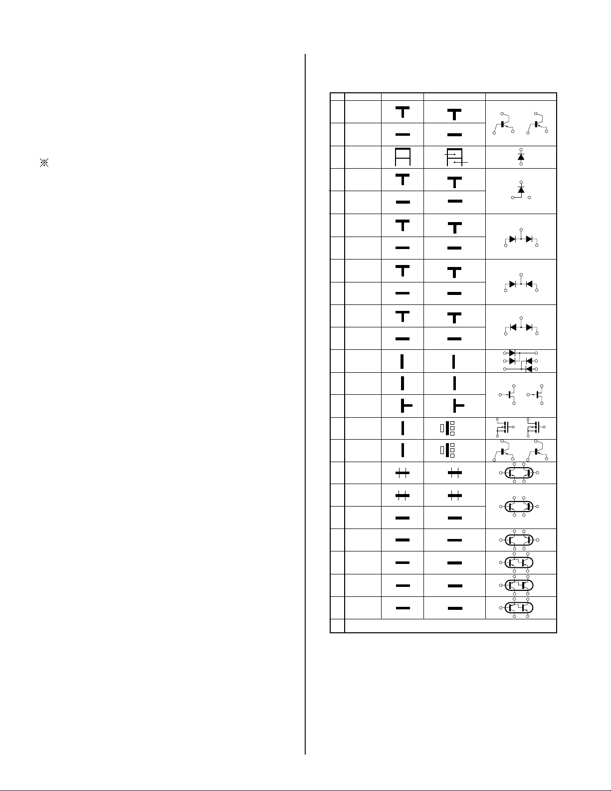
Terminal name of semiconductors in silk screen
printed circuit ( )
Device Printed symbol Terminal name
Transistor
1
Transistor
2
3
Diode
4
Diode
Diode
5
Diode
6
Diode
7
8
Diode
Diode
9
Diode
0
!¡
Diode
Diode
!™
Transistor
!£
(FET)
Transistor
!¢
(FET)
Transistor
!?
(FET)
Transistor
!§
Transistor
!¶
Transistor
!•
Transistor
!ª
Transistor
@º
Transistor
@¡
Transistor
@™
Transistor
@£
Discrete semiconductot
–
(Chip semiconductors that are not actually used are included.)
*
Collector
Base
Collector
Base
Cathode
Cathode
Anode
Cathode
Anode
Common
Anode
Common
Anode Cathode
Common
Anode
Common
Anode Anode
Common
Cathode
Common
Cathode
Anode
Anode
Cathode
Drain
Drain
B1 E1
C2
B2 C1
E2
B2 E2
C1
B1 C2
E1
B2 E2
C1
B1 C2
E1
B2 E2
C1
B1 C2
E1
E2
B1 E1
C2
(B2)
E1
B1
C1
(B2)
E1
E2
C2
Emitter
Emitter
Anode
(NC)
(NC)
Cathode
Anode
Cathode
Cathode
Cathode
Anode
Anode
Source
Gate
Source
Gate
Source
Drain
Gate
Emitter
Collector
Base
C1(B2)
E2
C2
B1
C1
Circuit
D
G
D
S
B1
B1
B1
B1
B1
B1
D
G
S
S
D
G
C1
E1
C1
E1
E1
C1
E2
C1
C1
G
S
C2
B2
E2
C2
B2
E2
E2
B2
C2
C2C1(B2)
E2
E2E1(B2)
C2
C2E1(B2)
C2
Ver.1.6
KDL-32S20L1/40S20L1
22
Page 23
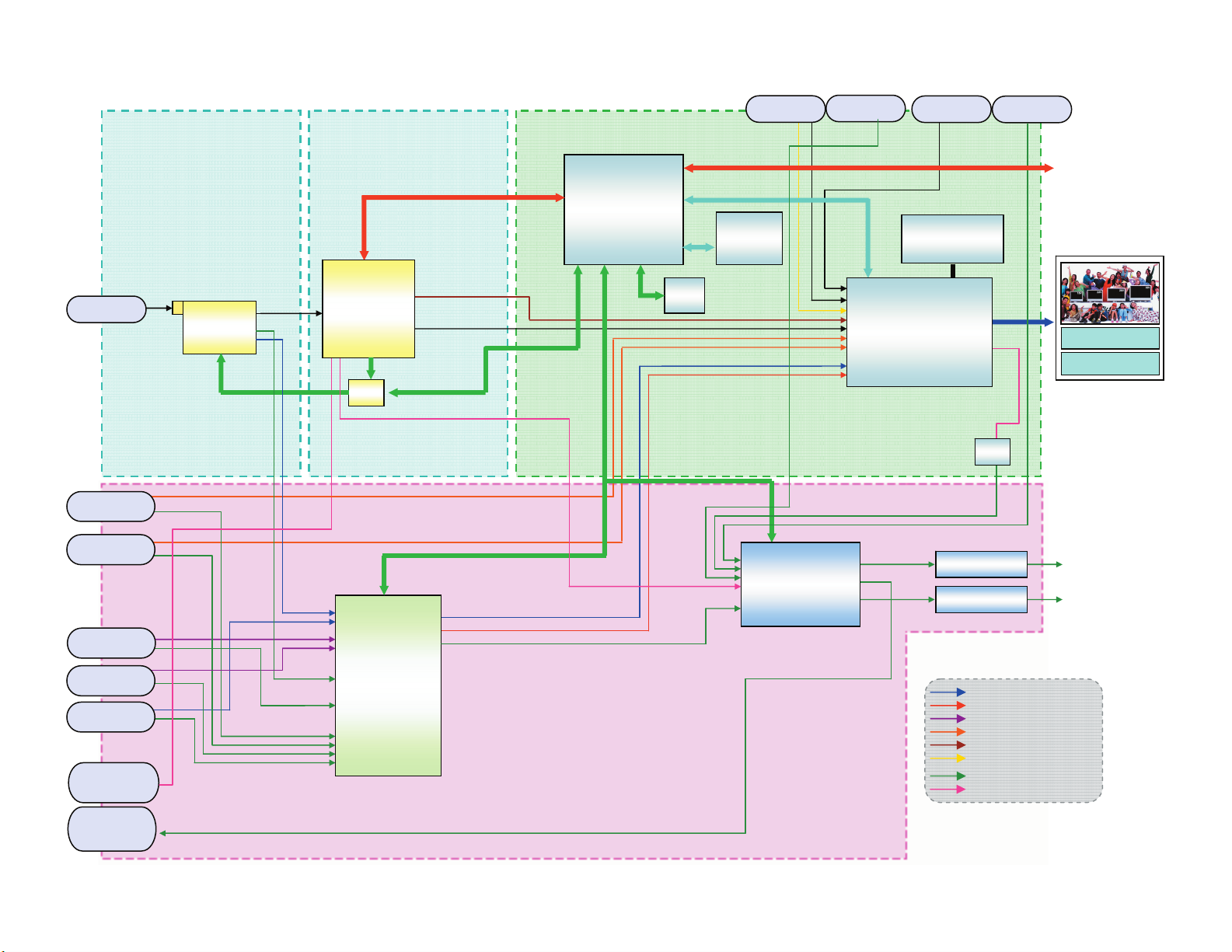
3-3. BLOCK DIAGRAM
KDL-32S20L1/40S20L1
Digital F/E BU
RF/Cable
UFE
UFE
Comp1
Comp2
QT QS
MPEG DEC.
IF
MPEG DEC.
CPU
CPU
ATi
x240H
ATi
x240H
I2S
SW
SW
SPDIF
CLK/Hs/Vs
I2C-B
UART
D-Comp[15:0]
Main Micro
MB91305
I2C-C
I2C-A
8bit Multiplex BUS
16bit
1MByte
BUS
EEP
Flash
MAP4400A
PC
Hs/Vs
AV mo use
Audio
for PC
TMDS
DDRSDRAM
4M x 32bit
Chroma Dec/IP
/Scalar
Trident SVP-PXs
HDMI
Audio Amp.
HP Amp.
HP Amp.
D/A
I2S
Audio
for DVI
ECSUART
Backlight
Inverter
Panel䋨WXGA䋩
(S)Video1
(S)Video2
Video3
Optical Audio
Out
Audio out
(Fix/Var.)
KDL-32S20L1/40S20L1
AV SW
CXA2069Q
AU
CVBS
Y/C
CVBS+Y/C
Analog-Component/RGB
Digital-Component
PC-RGB
Audio (Analog)
Audio (Digital)
23
Page 24
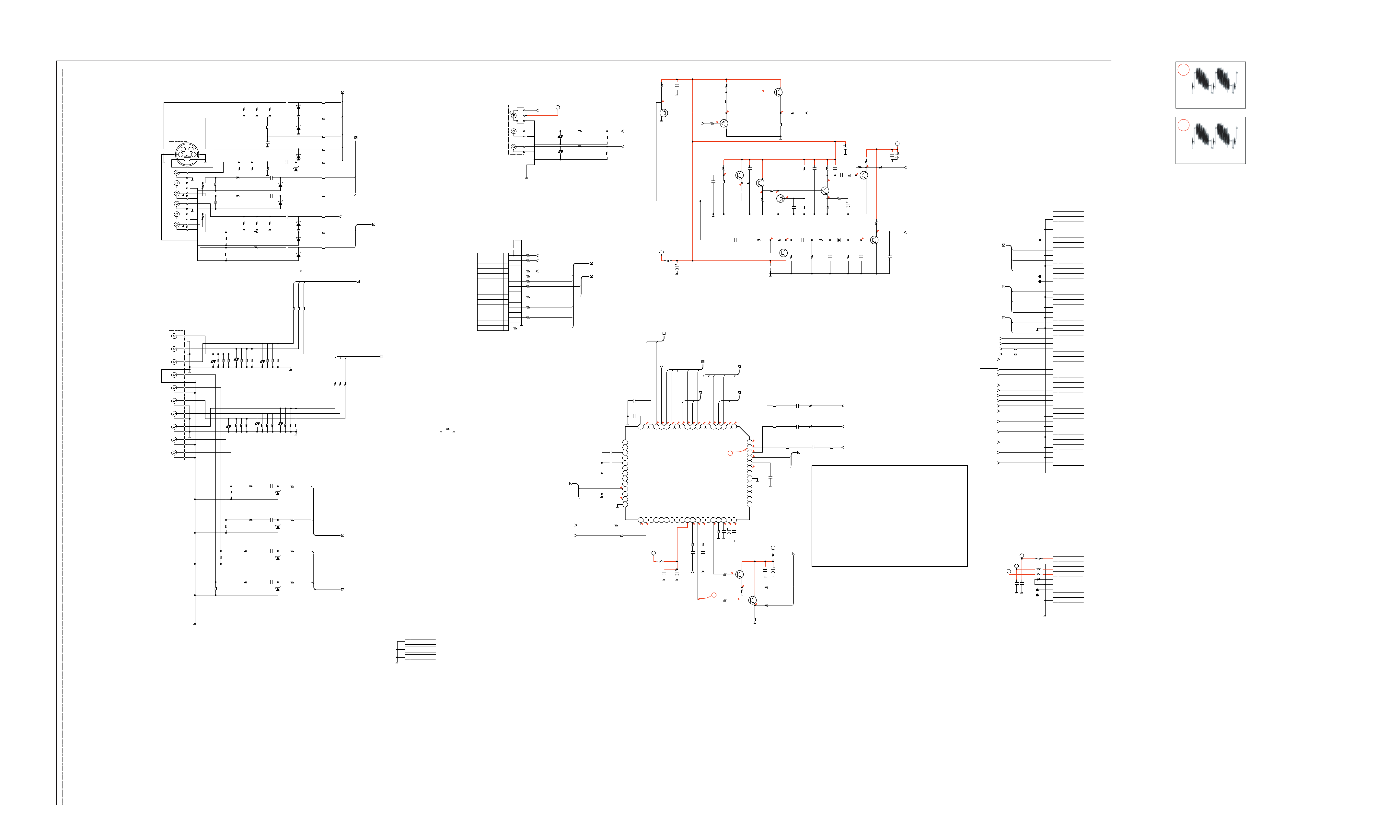
3-4. SCHEMATICS AND SUPPORTING INFORMATION
AU BOARD SCHEMATIC DIAGRAM (1 OF 2)
1 | 2 | 3 | 4 | 5 | 6 | 7 | 8 | 9 | 10 | 11 | 12 | 13 | 14 | 15 | 16 | 17 | 18 | 19 | 20 | 21 | 22 | 23
A
—
B
34
34
12
—
12
56
VideoInput1
7
R9045
0
8
J9001
CHIP
R9019
1608
9
10
11
13
12
14
15
16
17
18
20
19
1
2
3
4
5
6
7
8
9
10
11
12
13
14
15
16
17
18
19
20
R9046
CHIP
1608
470k
5%
R9020
470k
5%
0
VD9403
R9065
1/10W
RN-CP
R9004
470k
R9021
470k
5%
R9022
470k
5%
R9008
220
220
1/10W
RN-CP
0.5%
0.5%
VD9400
R9005
470k
5%
5%
C
—
D
—
E
—
F
—
G
—
H
—
I
—
J
—
K
—
L
—
VideoInput3
ComponentInput1
ComponentInput2
GRN
BLU
RED
WHT
RED
GRN
BLU
RED
WHT
RED
J9002
R9009
1/10W
RN-CP
0.5%
R9007
470k
R9006
220
5%
470k
5%
R9068
220
1/10W
RN-CP
0.5%
R9023
CHIP
R9024
CHIP
VD9404
0
0
R9066
1/10W
RN-CP
0.5%
R9016
1/10W
RN-CP
0.5%
KDL-32S20L1/40S20L1
AU BOARD WAVEFORMS
1
R6001
C6001
2.2k
0.1
1/10W
16V
RN-CP
B
5%
2.6
2SA1235TP-1EF
L6001
10uH
V3_IN_AU_L,V3_IN_AU_R
V3_IN_V
4.9
3.9
0.1
V3
S-2
S2-2
AV SW
LOUT3
YOUT3
COUT3
1608
Q6001
C6003
100
16V
Video2
4.4
4.4
C2
RV2
CXA2069Q-TL
IC2001
ROUT3
VOUT3
R2014
CHIP
C2016
1
16V
B
2012
C2015
16V
100
V_IN
R6002
100
1/10W
RN-CP
5%
C6006
0.1
16V
B
1608
V2_IN_C,V2_IN_S2SW,V2_IN_SSW,V2_IN_V,V2_IN_Y
V2_IN_AU_L,V2_IN_AU_R
4.9
0.1
3.9
4.4
0.1
9 10111213141516171819
V2
Y2
S-1
LV2
S2-1
TRAP2
V/YOUT2
VCC
LOUT2
ROUT2
4445464748495051
4.5
4.3
4.5
R2015
0
CHIP
0
C2017
1
16V
B
2012
SEL2_AU_R
SEL2_AU_L
R9057
100
1/10W
RN-CP
R9032
R9062
220
220
1/10W
1/10W
RN-CP
RN-CP
0.5%
0.5%
R9029
R9063
220
220
1/10W
1/10W
RN-CP
RN-CP
0.5%
0.5%
R9064
R9033
220
220
1/10W
1/10W
RN-CP
RN-CP
0.5%
0.5%
R9030
0
CHIP
R9031
0
CHIP
VD9405
R9014
220
1/10W
RN-CP
0.5%
R9015
220
220
1/10W
RN-CP
0.5%
VD9401
R9018
220
220
1/10W
RN-CP
0.5%
R9069
220
1/10W
RN-CP
0.5%
R9012
0
CHIP
R9013
0
CHIP
R9010
0
CHIP
R9011
0
CHIP
R9067
220
1/10W
RN-CP
0.5%
R9026
1/10W
RN-CP
0.5%
C9019
R9041
2.2
220
10V
1/10W
B
RN-CP
2012
0.5%
C9020
2.2
R9039
10V
75
B
1/10W
RN-CP
2012
5%
1608
B
10V
0.47
C9016
R9040
C9021
220
2.2
2012
MM3Z10VT1
MM3Z10VT1
C9022
C9023
2012
C9024
220
R9070
220
1/10W
RN-CP
0.5%
D9001
D9002
10V
2.2
10V
2012
16V
16V
2012
B
D9008
D9009
B
1
B
1
B
R9099
1/10W
RN-CP
R9100
1/10W
RN-CP
R9101
1/10W
RN-CP
R9102
1/10W
RN-CP
R9034
1/10W
RN-CP
5%
R9028
220
1/10W
RN-CP
0.5%
1k
5%
1k
5%
1k
5%
1k
5%
22
MM3Z10VT1
R9036
22
1/10W
RN-CP
5%
R9035
220
1/10W
RN-CP
0.5%
1/10W
RN-CP
0.5%
C9014
1
16V
B
2012
C9015
1
16V
B
2
012
R9042
220
1/10W
RN-CP
0.5%
R9025
1/10W
RN-CP
0.5%
R9017
220
1/10W
RN-CP
0.5%
VD9402
220
R9027
220
1/10W
RN-CP
0.5%
C9006
1
16V
B
2012
MM3Z10VT1
C9007
1
16V
B
2012
MM3Z10VT1
C9008
1
16V
B
2012
D9003
MM3Z10VT1
C9005
1
16V
B
2012
D9004
MM3Z10VT1
MM3Z10VT1
D9013
MM3Z10VT1
D9014
MM3Z10VT1
D9015
D9012
MM3Z10VT1
D9016
D9017
MM3Z10VT1
D9018
MM3Z10VT1
R9037
22
1/10W
RN-CP
5%
5%
R9058
100
1/10W
RN-CP
5%
R9059
1k
1/10W
RN-CP
5%
R9060
1k
1/10W
RN-CP
5%
R9061
100
1/10W
RN-CP
5%
R9095
1k
1/10W
RN-CP
5%
R9096
1k
1/10W
RN-CP
5%
R9078
100
1/10W
RN-CP
5%
R9097
1k
1/10W
RN-CP
5%
R9098
1k
1/10W
RN-CP
5%
R9038
22
1/10W
RN-CP
D2_IN_AU_L,D2_IN_AU_R
D1_IN_AU_L,D1_IN_AU_R
V1_IN_C,V1_IN_S2SW,V1_IN_SSW,V1_IN_V,V1_IN_Y
V1_IN_AU_L,V1_IN_AU_R
V3_IN_V
V3_IN_AU_L,V3_IN_AU_R
D1_IN_CB,D1_IN_CR,D1_IN_Y
D2_IN_CB,D2_IN_CR,D2_IN_Y
R9043
22
1/10W
RN-CP
R9044
22
1/10W
RN-CP
Opt/Audio Output
VideoInput2
R9542
0
HP_DET
HP_OUT_AU_L
AU_IN_GND
HP_OUT_AU_R
V2_IN_SSW
V2_IN_S2SW
V2_IN_AU_R
AU_IN_GND
V2_IN_AU_L
V2_IN_C
V2_IN_Y
V2_IN_V
CN9001
15P
D3.3V
VIN
VCC
GND
J9003
C9032
1000p
25V
CH
1
2
3
4
5
6
7
8
9
10
GND
11
12
GND
13
14
GND
15
FB9003
0
CHIP
R9150
CHIP
R9151
CHIP
R9152
R9153
R9154
R9155
R9156
R9157
R9158
0
0
SPDIF
VD9025
VD9026
HP_DET
HP_OUT_AU_L
HP_OUT_AU_R
CHIP0
CHIP0
CHIP0
CHIP0
CHIP0
CHIP0
CHIP0
D1_IN_AU_L,D1_IN_AU_R
IIC
SCL_B_5V
SDA_B_5V
R9333
CHIP
R9334
CHIP
0
0
C9511
0.22
16V
1608
C9508
0.22
16V
1608
C9510
0.22
16V
1608
B
AUOUT_AU_L
AUOUT_AU_R
C9507
0.22
16V
B
1608
C9506
0.22
16V
B
1608
20
RN-CP
1/10W
R2006
S2-3
21
S-3
22
V4
23
LV4
24
Y4
25
RV4
26
C4
27
S2-4
28
S-4
4.4
4.4
29
LV5
30
V5
4.4
4.4
31
RV5
32
ADR
100
RN-CP
1/10W
100
R2007
B
B
R9088
220k
1/10W
RN-CP
5%
R9089
220k
1/10W
RN-CP
5%
V2_IN_C,V2_IN_S2SW,V2_IN_SSW,V2_IN_V,V2_IN_Y
V2_IN_AU_L,V2_IN_AU_R
C9509
0.22
16V
B
1608
A9V
Video3
4.4
4.4
Y3
C3
LV3
RV3
SCL
DC OUT
SDA
AGND
3334353637383940414243
5.0
5.0
A9V
L2002
22uH
C2013
0.22
16V
B
1608
GNDterminal
1.2
R6007
47k
1/10W
RN-CP
0.5%
R6008
22k
1/10W
RN-CP
0.5%
1608
Video1
4.4
4.4
Y1
C1
RV1
YIN1
COUT2
MUTE
4.4
C2018
R2017
0.22
0
16V
B
CHIP
1608
R2019
100
1/10W
RN-CP
5%
Q2001
2SC3052EF-T1-LEF
2
R2020
100
1/10W
RN-CP
5%
R6004
2.2k
1/10W
RN-CP
0.5%
CHIP
0
R6003
1.9
Q6002
2SA1235TP-1EF
Q6011
2SC3052EF-T1-LEF
2.7
2.7
C6009
2.2
16V
C
2012
C6005
0.022
25V
B
1608
4.4
3.9
3.9
12345678
V1
LV1
1
COUT1
YOUT1
TRAP1
ROUT1
VOUT1
LOUT1
BIAS
CIN1
4.4
4.4
3.9
C2019
C2020
0.22
10
16V
16V
B
1608
4.4
4.3
Q2002
2SC3052EF-T1-LEF
2.0
C6026
0.1
16V
B
1608
R6052
100
2.0
R6009
4.7k
1/10W
RN-CP
5%
V1_IN_C,V1_IN_S2SW,V1_IN_SSW,V1_IN_V,V1_IN_Y
V1_IN_AU_L,V1_IN_AU_R
4.4
RTV
64
4.2
TV
63
4.4
LTV
62
4.4
RV6
61
V6
60
4.4
LV6
59
1608
B
58
16V
R2037
1/10W
RN-CP
0.22
57
C9505
56
55
54
53
52
C2021
0.22
16V
B
1608
3.7
470
5%
3.6
R2038
470
1/10W
RN-CP
5%
VGND
Q6012
2SC3052EF-T1-LEF
R6013
2.2k
1/10W
RN-CP
5%
1.8
R6012
470
1/10W
RN-CP
5%
R6017
1M
1/10W
RN-CP
6
8.
5%
Q6004
2SA1235TP-1EF
C6011
0.1
16V
B
1608
R2023
1/10W
R2024
1/10W
100
R2030
1/10W
A9V
10uH
L2003
C2023
100
16V
0
R2027
CHIP
R2028
0
CHIP
Q6009
2SC3052EF-T1-LEF
1.4
R6040
0
CHIP
R6039
1608
330
1/10W
RN-CP
5%
R6014
56k
1/10W
RN-CP
0.5%
1608
Q6013
2SA1235TP-1EF
1.3
R6020
10k
C6016
1/10W
0.022
RN-CP
25V
0.5%
B
1608
3.5
C6014
4700p
R6021
4.7k
1/10W
RN-CP
5%
1k
RN-CP
C2024
1
16V
B
2012
1k
RN-CP
C2025
1
16V
B
2012
SEL2_C,SEL2_Y/CV
V_AVSW
C6025
R6029
0.1
16V
1/10W
B
RN-CP
1608
R6026
1/10W
RN-CP
R6028
3.9k
1/10W
50V
RN-CP
B
0.5%
1608
R6025
2.7k
1/10W
RN-CP
0.5%
R2033
0
R2034
0
CHIP
C2026
2.2
10V
B
2012
D2_IN_AU_L,D2_IN_AU_R
C6027
100
16V
R6030
C6018
C6024
4.7k
2.2
1000p
3.9k
0.5%
1k
5%
1/10W
16V
25V
RN-CP
C
CH
2012
1608
3.2
Q6005
2SC3052EF-T1-LEF
R6023
1k
1/10W
RN-CP
5%
1.2
1608
C6023
100
10V
5%
1608
2SC3052EF-T1-LEF
D6001
RB501V-40TE-17
R6032
C6019
2200p
1/10W
50V
RN-CP
B
1608
TV_R_UC
TV_L_UC
R2039
0
CHIP
V_AVSW
VideoSystem
TV : AnalogTuner
IN1: Video1
IN2: Video2
IN3: Video3
IN4: DigitalTuner
IN5:
IN6:
OUT1:
OUT2: C-Video
OUT3: VideoOutput
D3.3V
R6033
Q6008
1M
5%
R6051
-0.9
4.7k
1/10W
RN-CP
1608
1M
5%
0.
R6034
3.2
Q6007
2SC3052EF-T1-LEF
R6037
1k
1/10W
RN-CP
5%
0.
7
C6020
0.22
16V
B
1608
C6015
C6017
0.1
47
16V
16V
B
1608
0
0
C6022
6.3V
2012
M_HSYNC
V_DET
4.7
B
CXA2069Q I/O list
AudioSystem
TV : AnalogTuner
IN1: Video1
IN2: Video2
IN3: Video3
IN4: DigitalTuner(RECOUT)
IN5: Component1
IN6: Component2
OUT1:
OUT2: C-Video(to Trident)
OUT3: VideoOutput
Vp-p (H)
4.0
2
4.0 Vp-p (H)
B
1
Y1/G1
2
GND
3
CB1/B1
4
0uH
0uH
0uH
GND
5
CR1/R1
6
L3_1/MODE_1
7
N.C./FB_1
8
Y2/G2
9
GND
10
CB2/B2
11
GND
12
CR2/R2
13
L3_2/MODE_2
14
N.C./FB_2
15
N.C./AVLINK(AEP)
16
Y3
17
GND
18
CB3
19
GND
20
CR3
21
GND
22
SEL2_Y/CV
23
GND
24
SEL2_C
25
V_DET
26
M_HSYNC
27
SDA_B_5V
28
SCL_B_5V
29
AU_PROT
30
REC_MUTE/TV_L(AEP)
AC_OFF_DET_AU/TV_R_(AEP)
31
LINE_MUTE
32
AU_OPT_OUT_MUTE
33
RESET_AUDIO
34
SP_MUTE
35
SP_SD_MUTE
36
HP_MUTE
37
HP_DET
38
HDMI_L
39
AU_GND
40
HDMI_R
41
AU_GND
42
DVI_L
43
AU_GND
44
DVI_R
45
AU_GND
46
PC_IN_L
47
AU_GND
48
PC_IN_R
49
CN9501
49P
WHT
TO BU BOARD
CN1001
1
A9V
2
GND
3
D5V
4
D3.3V
5
GND
6
GND
7
DTT_LOG
8
AV_MOUSE
9
GND
CN9502
9P
TO BU BOARD
CN7008
B
JL9507
D1_IN_CB,D1_IN_CR,D1_IN_Y
JL9509
JL9510
D2_IN_CB,D2_IN_CR,D2_IN_Y
SEL2_C,SEL2_Y/CV
V_DET
M_HSYNC
SDA_B_5V
SCL_B_5V
AU_PROT
AC_OFF_DET_AU
LINE_MUTE
RESET_AUDIO
SP_MUTE
SP_SD_MUTE
HP_MUTE
HP_DET
HDMI_L
HDMI_R
DVI_L
DVI_R
PC_IN_L
PC_IN_R
D3.3V
D3.3V
R9501
R9502
C9501
1000p
CHIP0
CHIP
0
A9V
A9V
D5V
D5V
25V
CH
1608
C9502
1000p
25V
CH
1608
L9503
L9504
L9505
JL9504
JL9505
R9506
39k
RN-CP
1/10W
0.5%
1608
EARTH TERMINAL
M
1
1
1
CN9521
EARTH TERMINAL
CN9522
EARTH TERMINAL
CN9523
—
N
AU MOUNT (1/2)
—
O
—
P
KDL-32S20L1/40S20L1 24
A/V SWITCH
INPUTS
9-883-706-01<WAX2>AU-P1
Page 25
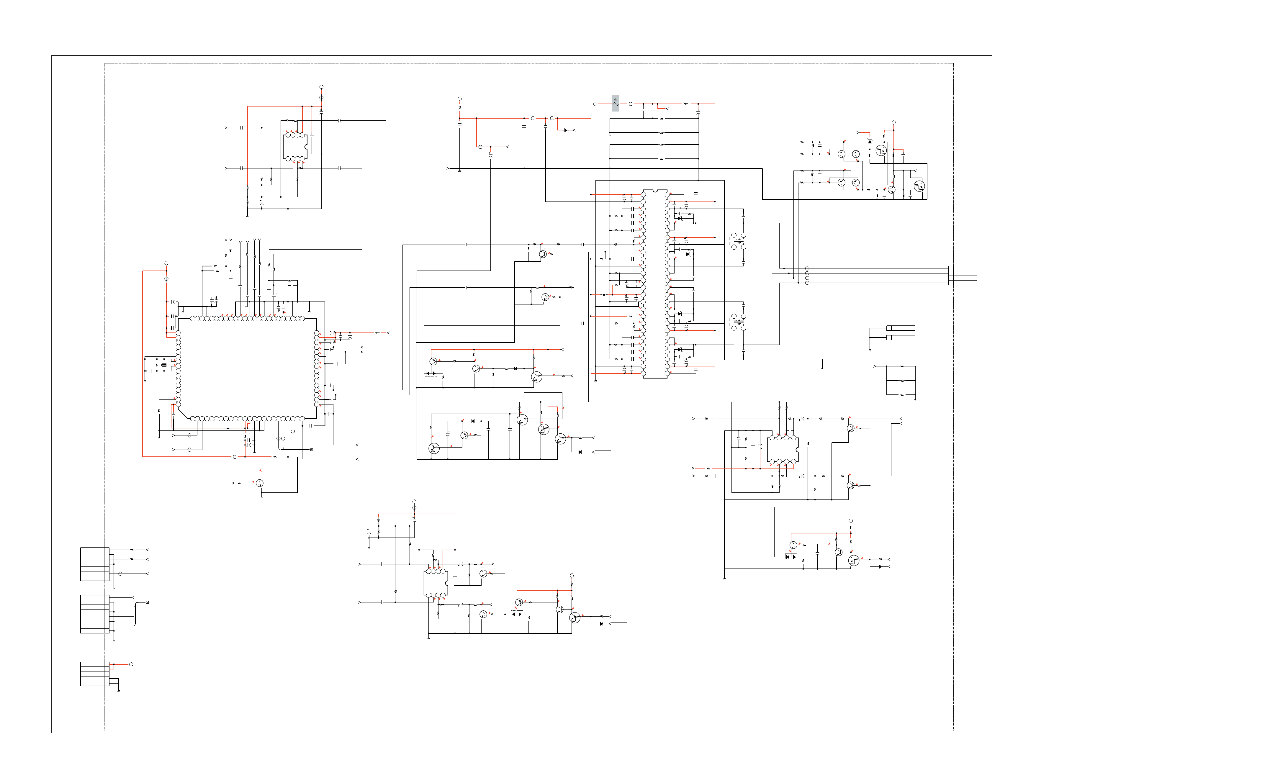
AU BOARD SCHEMATIC DIAGRAM (2 OF 2)
1 | 2 | 3 | 4 | 5 | 6 | 7 | 8 | 9 | 10 | 11 | 12 | 13 | 14 | 15 | 16 | 17 | 18 | 19 | 20 | 21 | 22 |
KDL-32S20L1/40S20L1
A
—
B
—
C
—
D
—
E
—
F
—
G
—
H
—
I
—
J
—
K
—
L
—
M
—
N
TO QS BOARD
CN7314
TO QT BOARD
CN7803
CN7501
7P
CN7502
SPDIF
DATA0
A9V
A9V
5.0
R7622
1/10W
4.7k
RN-CP
0.5%
8765
VCC
AOUTPUT
R7087
1/10W
5.0
1M
C7065
1000p
25V
CH
1608
AU_PRE_GND
C7076
R7088
22k
1/10W
C7072
100
25V
0.0
A9V
10uH
L9606
C7075
1
25V
2012
1
25V
2012
2SC3052EF-T1-LEF
0.0
Q7009
2SA1235TP-1EF
C7613
10
16V
1608
B
16V
0.1
C7612
C7614
10
16V
Q7008
D7006
MMDL914T1
0.0
R7102
10k
1/10W
RN-CP
R7634
2.2k
1/10W
RN-CP
0.5%
R7632
47k
1/10W
RN-CP
0.5%
R7635
2.2k
1/10W
RN-CP
0.5%
R7633
47k
1/10W
RN-CP
0.5%
R7093
1/10W
L7006
16V
47
C7073
47k
0.0
0.0
2.8
2.8
C7082
1000p
25V
CH
1608
0.0
AUOUT_AU_L
0.0
R7641
2.2k
1/10W
RN-CP
5%
Q7603
2SC3624A-T1L15L16
LINE_OUT
0.0
AUOUT_AU_R
0.0
R7642
2.2k
1/10W
RN-CP
5%
Q7604
2SC3624A-T1L15L16
RN-CP
1/10W
5%
100k
R7101
C7083
0.22
25V
2012
R7103
5.6k
1/10W
RN-CP
B
C9512
1000p
25V
CH
1608
AU_HP9V
D7007
MMDL914T1
CHIP
0
R7112
RT1N441M-TP-1
0.0
D7603
M1MA152WA-T1
FB9101
0uH
R7114
2.2k
1/10W
RN-CP
0.5%
R7113
47k
1/10W
RN-CP
0.5%
2SC3624A-T1L15L16
R7115
1/10W
RN-CP
0.0
5%
Q7011
R7657
22k
1/10W
RN-CP
8.9
5%
Q7609
2SA1235TP-1EF
R7658
1M
1/10W
RN-CP
5%
L7011
C7063
1000p
25V
CH
1608
0.0
0.0
Q7012
R7116
2.2k
1/10W
RN-CP
0.5%
0.0
47k
0.5%
Q7013
2SC3624A-T1L15L16
R7111
47k
1/10W
0.0
0.0
Q7010
RT1N441M-TP-1
47k
R7015
RN-CP
1/10W
5%
0.0
Q7019
RT1N441M-TP-1
Q7610
2SC3052EF-T1-LEF
MMDL914T1
R7120
0
CHIP
R7118
2.2k
1/10W
0.0
R7119
2.2k
1/10W
AU_15V_M
2.8
2.8
47k
RN-CP
R7014
1/10W
0.0
Q7020
RT1N441M-TP-1
R7660
1/10W
RN-CP
8.9
R7117
10k
1/10W
RN-CP
47k
5%
D7005
0.0
R7122
0
CHIP
SP_SD_MUTE
2.8
MMDL914T1
A9V
R7662
47k
1/10W
RN-CP
0.0
RT1N441M-TP-1
AU_+8V
R7661
CHIP
5%
R7017
10k
1/10W
RN-CP
5%
D7013
0
Q7611
C7086
25V
2012
C7087
25V
2012
12
4849505152
4147 46 45 44 43 42
34353637383940
27282930313233
15.5
C7109
C7110
15.5
15.5
7.2
7.2
C7111
C7112
15.5
L7008
22uH
C7105
0.1
25V
B
330p
1608
7.2
D7009
P6SMBJ30A-5
C7106
0.1
25V
B
330p
7.2
P6SMBJ30A-5
D7011
P6SMBJ30A-5
330p
C7107
0.1
25V
B
2012
D7012
7.2
P6SMBJ30A-5
330p
C7108
0.1
25V
B
2012
009:6G
HP_R_IN
AU_HP9V
HP_L_IN
2012
C7118
C7115
25V
1
C7114
100
35V
100
35V
C7116
C7117
D7010
100
35V
100
35V
R7139
C7119
2012
C7120
2012
R7140
R7141
R7138
18
25V
25V
18
18
18
1
1
C7121
25V
2012
C7113
1
470
25V
R7601
1/10W
RN-CP
R7602
1/10W
RN-CP
4.7k
4.7k
5%
R7600
5%
CHIP
0.0
C7147
100k
R7659
10k
1/10W
RN-CP
5%
D7604
MMDL914T1
2012
1
25V
B
A9V
R7067
10k
1/10W
RN-CP
2.9
1
1
HP_MUTE
AC_OFF_DET_AU
R7154
100k
1/10W
RN-CP
R7155
0
CHIP
R7156
47k
1/10W
RN-CP
CN7001
CN7002
R7682
CHIP
1608
R7683
CHIP
1608
R7684
CHIP
1608
HP_OUT
C7064
1000p
25V
CH
1608
Q7022
RT1N141M-TP-1
C7148
0.1
16V
B
1608
0
0
0
HP_OUT_AU_R
HP_OUT_AU_L
AU_PROT
TO Speakers
CN7000
4P
1
L+
2
L-
3
R-
4
R+
TO DETECT
C7127
1
25V
R7146
B
100k
1/10W
2012
RN-CP
R7142
100k
1/10W
RN-CP
R7143
100k
1/10W
RN-CP
R7144
100k
1/10W
RN-CP
R7145
100k
1/10W
RN-CP
C7123
1
25V
B
3216
4
1
23
L7009
10uH
C7124
1
25V
B
3216
C7125
1
25V
B
3216
4
1
23
L7010
10uH
C7126
1
25V
B
3216
RN-CP
1/10W
R7630
100k
R7631
1/10W
RN-CP
5.05.0
4321
A-INPUT
A+INPUT
GNDB+INPUT
B-INPUT
BOUTPUT
5.0
5.0
C7615
R7628
82k
1/10W
RN-CP
5%
RN-CP
1/10W
3.3k
R7629
5%
0.0
D7602
M1MA152WA-T1
3.3k
5%
C7617
82k
47
16V
5%
C7616
100p
50V
CH
1608
AOUTPUT
5%
IC7602
NJM3414AV(TE2)
VCC
8765
100p
50V
CH
1608
C7618
47
16V
R7636
1/10W
RN-CP
8.9
Q7602
2SA1235TP-1EF
R7637
1/10W
RN-CP
RN-CP
1/10W
5%
R7627
C7609
1608
RN-CP
B
C7611
1/10W
16V
10
10k
0.1
16V
R7614
C7610
5%
10
16V
RN-CP
1/10W
0.5%
12k
R7615
RN-CP
1/10W
5%
R7626
5.0
100k
C7601
0.1
16V
B
1608
0
C7602
0.1
16V
B
1608
AU_PRE_GND
22k
5%
1M
5%
5%
R7147
100k
1/10W
RN-CP
FB7000
FB7001
FB7002
FB7003
RN-CP
1/10W
100k
R7639
0uH
0uH
0uH
0uH
7.2
C7128
2SA1235TP-1EF
1
25V
B
2012
7.1
2SA1235TP-1EF
P_GND
R7644
220
1/10W
RN-CP
5%
R7646
220
1/10W
RN-CP
5%
RN-CP
1/10W
100k
R7643
1608
B
25V
0.1
C7619
2SC3052EF-T1-LEF
Q7014
Q7015
8.9
Q7605
AU_15V_M
7.2
2SA1235TP-1EF
7.1
Q7017
2SA1235TP-1EF
R7651
0
CHIP
R7652
0
2SC3624A-T1L15L16
CHIP
R7650
47k
1/10W
RN-CP
5%
D7001
MM3Z11VT1
0.0
Q7016
0.0
0.0
0.0
R7655
4.7k
1/10W
RN-CP
5%
Q7607
0.0
0.0
R7656
4.7k
1/10W
RN-CP
5%
A9V
R7653
0
CHIP
R7654
47k
1/10W
RN-CP
5%
0.0
Q7608
RT1N441M-TP-1
R7066
6.8k
1/10W
RN-CP
Q7021
RT1N141M-TP-1
Q7018
2SC3052EF-T1-LEF
R7152
10k
1/10W
RN-CP
R7153
1/10W
RN-CP
P_GND
AU_PRE_GND
Q7606
2SC3624A-T1L15L16
2.8
FB9100
PS7001
R7020
47k
1/10W
RN-CP
5%
R7130
1/10W
RN-CP
R7131
1/10W
RN-CP
R7663
10k
1/10W
RN-CP
5%
D7605
0.5%
0.5%
R7124
1/10W
RN-CP
R7125
1/10W
RN-CP
L7007
10uH
6.8k
6.8k
6.8k
0.5%
6.8k
0.5%
4A
25V
AU_GND
C7088
C7092
1500p
50V
B
1608
C7094
150p
50V
CH
1608
R7126
10k
1/10W
RN-CP
0.5%
R7127
22k
1/10W
RN-CP
0.5%
C7090
10
16V
R7128
180k
1/10W
RN-CP
0.5%
16V
10
C7091
R7129
10k
1/10W
RN-CP
0.5%
C7096
1500p
50V
B
1608
C7098
150p
50V
CH
1608
C7089
10
16V
002:4D
LINE_MUTE
AC_OFF_DET_AU
10
16V
C7093
150p
50V
CH
1608
C7095
1500p
50V
B
1608
R7132
100k
1/10W
RN-CP
0.5%
C7101
0.1
25V
B
2012
1/10W
R7133
100k
1/10W
RN-CP
0.5%
C7097
150p
50V
CH
1608
C7099
1500p
50V
B
1608
AU_15V
1
1
P_GND
SP_MUTE
AC_OFF_DET_AU
2.8
MMDL914T1
0uH
C7100
C7102
C7103
2012
RN-CP
10k
R7158
C7104
25V
2012
25V
2012
0.1
25V
25V
2012
C7062
C7061
1000p
1000p
25V
CH
1608
DIGITAL AMP
M61571AFP
IC7007
DVDD1
DGND1
PWM2A1
PWM1A1
PWM1B1
PWM2B1
OP1O
IN1
STBY/MUTE
MUTEC
SUB
VCOR
AGND
VREF
AVCC
SUB
CLK
CLKCTRL
IN2
OP2O
PWM2B2
PWM1B2
PWM1A2
PWM2A2
DGND2
DVDD2 HB A2
OUTA1
OUTA1
OUTB1
OUTB1
OUTB2
OUTB2
OUTA2
OUTA2
HBA1
VDA1
VSA1
VSA1
VDB1
VSB1
VSB1
HBB1
HBB2
VSB2
VSB2
VDB2
VSA2
VSA2
VDA2
R7134
CHIP
R7135
CHIP
R7136
CHIP
R7137
CHIP
SUB
SUB
0
0
0
0
AU_15V_M
25V
CH
1608
0.1
B
4.5
4.5
4.5
54321
4.5
4.5
0.0
8.8
0.8.
1211109876
4.5
0.1
B
B
9.0
4.5
19181716151413
4.5
20 21 22 23 24 25 26
4.5
4.5
4.5
4.5
4.5
0.1
B
L7012
C7044
AU_PRE_GND
B
50V
1608
C7043
0.1
16V
1608
2200p
DTV_IN
B
40
39
38
37
36
35
34
33
32
31
30
29
28
27
26
25
C7042
47
16V
C7051
1
16V
B
2012
C7605
16V
47
AU_PRE_GND
D7004
M1MA152WA-T1
R7004
1/10W
RN-CP
0.0
Q7007
RT1N441M-TP-1
RN-CP
1/10W
10k
0.5%
R7620
5.0
0.5%
GND B+I N
4321
RN-CP
1/10W
0.5%
10k
R7623
AU_PRE_GND
14.32.4
14.3
Q7005
2SA1235TP-1EF
47k
5%
R7621
1/10W
4.7k
RN-CP
5.0
B-IN
BOUTPUT
A-IN
A+IN
5.0
5.0
C7052
1
16V
B
2012
16V
C7053
7.3
7.4
3.8
C7048
3.8
2200p
50V
B
1608
3.8
C7056
2200p
3.8
1608
B
1608
0.0
0.0
0.0
B
1608
16V
10
50V
50V
B
50V
2200p
2200p
C7045
C7054
C7046
16V
10
C7055
0.1
25V
B
1608
B
50V
1608
2200p
FIX/VAR_L_IN
FIX/VAR_R_IN
C7057
C7047
47
FIX/VAR_L_IN
FIX/VAR_R_IN
HP_L_IN
HP_R_IN
0.5%
RN-CP
1/10W
12k
R7603
16V
10
C7600
AU_PRE_GND
L7005
10uH
C7603
16V
2012
C7604
16V
2012
0.5%
RN-CP
1/10W
15k
R7604
1
B
1
B
AU_+8V
R7605
1/10W
RN-CP
R7606
1/10W
RN-CP
47k
5%
A9V
L7013
47k
5%
IC7601
NJM4558V-TE2
OP AMP
R7062
IC7003
NJM4558V-TE2
OP AMP
R7054
47k
1/10W
RN-CP
C7034
10
16V
5%
4.7k
R7050
10k
1
B
16V
2012
10
C7038
3.8
47484950515253
ASG
SC4_IN_L
SC4_IN_R
DVSS
I2S_DA_IN2NCI2S_CL3
FB7006
R7055
100k
1/10W
RN-CP
R7061
1/10W
10k
8.2k
1/10W
RN-CP
RN-CP
5.0
5.0
B-IN
A+IN
GND B+IN
4321
R7064
10k
1/10W
RN-CP
0.5%
RN-CP
1/10W
4.7k
0.5%
R7056
RN-CP
1/10W
15k
R7057
1
B
15k
16V
2012
C7036
R7059
1
B
16V
2012
C7037
16V
3.7
0.1
3.8
0uH
25V
C7039
NC
AHVSS
AHVSS
AGNDC
I2S_WS3
RESETQ
I2S_DA_IN3
19 20 21 22 23 24
0uH
FB7007
C7040
0.1
25V
B
2012
5.0
BOUTPUT
A-IN
5.0
R7063
1/10W
8.2k
RN-CP
B
1608
SC3_OUOT_L
I2S_DA_IN4
0uH
FB7008
8765
VCC
AOUTPUT
5.0
5.0
414243444546
CAPL_M
SC3_OUT_R
AHVSUP
CAPL_A
SC1_OUT_L
SC1_OUT_R
VREF1
SC2_OUT_L
SC2_OUT_R
DACM_SL
DACM_SR
DACM_SUB
DACM_C
DACM_L
DACM_R
VREF2
DACA_L
DACA_R
C7024
1
16V
B
HDMI_R
SEL2_AU_R
3.8
4.4
VREFTOP
SC1_IN_R
I2S_DA_IN1
I2S_DEL_IN
R7018
0
CHIP
RESET_AUDIO
2012
C7025
1
16V
B
2012
0.5%
RN-CP
1/10W
12k
R7039
0.5%
RN-CP
1/10W
15k
R7040
SEL2_AU_L
PC_IN_R
0.5%
RN-CP
1/10W
4.7k
R7033
R7037
1/10W
RN-CP
C7023
1
16V
B
2012
C7027
1
16V
B
2012
3.8
3.8
54555657585960
ASG
SC1_IN_L
SC2_IN_R
MAP4400A-QA-B2-501
AUDIO DSP
I2S_DEL_OUT
I2S_DEL_WS
I2S_DEL_WS
R7019
0
CHIP
C7030
0.1
25V
B
1608
L7004
R7035
100k
1/10W
RN-CP
2SC3052EF-T1-LEF
HDMI_L
HDMI_R
R7031
4.7k
1/10W
R7032
RN-CP
15k
0.5%
D5V
L7002
C7011
47
16V
AU_PRE_GND
B
25V
0.1
C7010
C7060
1000p
25V
CH
1608
100k
C7005
CHIP
R7011
C7014
470p
50V
B
1608
SCL_B_5V
AU_PRE_GND
SDA_B_5V
2.3
X7000
18.432MHz
0.0
1.5p
C7004
1.5p
AU_PRE_GND
0
R7012
R7503
R7501
0uH
R7504
0
0
1
TV_R
2
GND
3
TV_L
4
GND
5
N.C
6
TV_V
7
N.C
1
GND
2
3
GND
4
BCK
5
GND
6
LRCK
7
GND
8
SPDIF
TV_R_UC
TV_L_UC
V_IN
DTV_IN
65
66
67
68
69
70
71
72
73
74
75
76
77
78
79
80
AVSUP
AVSUP
ANA_IN1+
ANA_IN-
ANA_IN2+
TESTEN
XTAL_IN
XTAL_OUT
TP
AUD_CL_OUT
NC
SPDIF_OUT
D_CTR_I/O_1
D_CTR_I/O_0
ADR_SEL
STANDBYQ
FB7004
0uH
FB7005
0uH
NC
NC
1234
1/10W
1608
B
25V
0.1
C7020
16V
10
C7019
61626364
NC
AVSS
AVSS
SC5_IN_R
I2C_CL
I2C_DA
I2S_CL
I2S_WS
567891011
R7034
15k
1/10W
RN-CP
0.5%
1608
C7021
1
16V
B
2012
SC5_IN_L
I2S_DATA_OUT
HDMI_L
R7049
47k
1/10W
RN-CP
AU_PRE_GND
DVI_R
DVI_L
PC_IN_L
R7041
10k
10k
R7045
RN-CP
1
16V
C7033
3.8
SC2_IN_L
B
C7029
ASG
2012
1
B
16V
3.8
SC3_IN_R
2012
SC3_IN_L
1/10W
R7047
C7035
3.8
10k
5%
IC7001
DVSUP
DVSUP
DVSS
DVSS
12 13 14 15 16 17 18
C7015
220p
50V
B
1608
C7028
47
AU_PRE_GND
16V
4.6
0.0
Q7002
RESET
AU_PRE_GND
—
O
—
UNREG15V
UNREG15V
CN7503
TO G1 BOARD
CN6202
OR
TO G2 BOARD
CN6200
AU_GND
AU_GND
5P
1
2
NC
3
4
5
AU_15V
AU_GND
AU MOUNT (2/2)
AUDIO
P
9-883-706-01<WAX2>AU-P2
KDL-32S20L1/40S20L1 25
Page 26

KDL-32S20L1/40S20L1
AU
A
B
C
D
[A/V SWITCH, INPUTS, AUDIO]
COMPONENT SIDE
1
CN9502
CN9522
CN9522
A9521
A9521
A9525
A9521
ANA
R9541 R9542
U
R9549
K
R9531 R9532 R9533 R9534
A B C D E
A9522
A9526
A9522
A9522
CN9521
CN9521
DIG
R9550
1
L9503
C9502
JL9501
JL9501
A-1179-
WCG
R9543
R9551
L9504
C9501
2345678910111213
CN9502
CN9502
91
91
9
JL9504
JL9504
JL9505
JL9505
L9505
JL9503
JL9503
JL9502
JL9502
R9535
L6001
L6001
AU BOARD LOCATOR LIST
DIODE TRANSISTOR
C9503
R9501
CN9501
JL9509
JL9509
1
1
1
2
JL9510
J9003
2
2
JL9507
JL9507
JL9510
CN9501
R9502
C9504
1-869-849-15
(172722815)
J9003
J9003
A9524
CN9523
A9524
A9524
CN9523
CN7001
CN7001
C7109
C7072
C7083
R7132
R7132
C7101
C7101
C7102
R7158
R7158
R7133
C7115
C7115C7116
C7088C7089
C7088
C7100
1
C7100
IC7007
261
261
IC7007
C7104
26
C7104
C7116
C7072
L7005
D7003
C7083
D7005
L7005
R7020
R7020
D7005
C7054
D7003
C7090C7091
C7090
L7007
L7007
C7102C7103
C7103
R7133
C7091
IC7007
R7136
R7137
R7135
C7089
L7008
R7136
R7134
R7134
L7008
C7061
C7062
CN7002
CN7002
R7138
C7109
R7138
C7114
C7114
L7009L7010
C7118
C7118
52 27
52 27
52
C7135
C7124
C7124
R7139R7140
R7139R7140
C7110
C7135
C7119
C7110
C7119
C7120
C7120
C7121
27
C7121
C7117
C7113
C7113
C7111
C7117
R7141
R7141
C7111
C7112
C7112
C7136
C7125
C7125
L7010
C7136
C7123
C7123
L7009
FB7000
FB7000
C7143
C7143
CN7000
1
1
1
FB7001
FB7001
CN7000
CN7000
4
4
FB7002
4
FB7002
C7144
C7144
FB7003
FB7003
C7126
C7126
Q2001
R2030
C2022
Q2002
C2026
R2030
C2022
C2020
IC2001
C2018
52
C2040
C2042
C9505
R2017
C2026
64
L2003
R2019
51
L2003
CN7502
CN7502
JL7501
JL7501
C2023
C2023
L2002
R2027
R2028
R2037
R2038
L2002
C2011
C2013
R2037
R2038
R2027
R2028
C2015
Q2001
Q2002
BE
BE
BE
BE
C2021
C2018
C2020
IC2001
C2021
R2020
51 33
51 33
52
52
64
64
1
CN9532
C2015
C2011
C2013
R2017
R2019
R2020
IC2001
JL9002 JL9003JL9004
JL9001
R9158
JL9002
JL9004
FB9003
C2041
C9026
81
81
R7032
C7021
R2007
R2006
33
32
32
20
20
191
191
19
JL9001
R9157
JL9003
15
R7034
C7023
R2007
R2006
32
20
R7038
C7027
JL9005
R9154
CN9001
CN9001
CN7501
R7046
R7042
C7029
C7033
C9509
C9508
C9506
C9507
JL9005
R7048
C7035
R9153
R7057
R7059
C7036
C7037
36
C7618
R7626
R9152
CN9001
R7503
R9150
C9032
1
115
115
R7504
35
R7503
CN7501CN7502
CN7501
R7504
R9151
71
71
R7501
R7501
R7683
R7684
C7617
C7617
C7618
C7611
C7611
R7682
R7615
R7615
R7507
1
L7012
2
C7073
C7073
L7006
C7610
R7600
L7006
R7626
R7629
C7610
R7600
R7629
R7614
R7614
C7609
A9523
C7609
A9523
A9523
L9606
L7012
C7004
C7005
C7065
L7002
L7002
R7011
X7000
C7028
C7044
C7011
C7010
C7004C7005
X7000
C7014
R7013
C7028
C7044
C7060
R7011
R7013
R7018
C7010
65
80
R7012
C7020
C7011
C7043
C7020
65
65
80
80
1
FB7004
R7049
1
1
R7061
R7062
C7024
IC7003
R7049
5
C7024
R7061
R7062
8
C7043
C7019
C7019
R7032
R7034
R7038
C7021
C7027
C7023
64
FB7005
R7012
14
FHC16 402 AD B
C7025
R7063
R7054
4
C7025
R7054
#5#8
#5#8
R7042
C7029
IC7001
C7015
5
5
C7057
R7064
#1 #4
#1 #4
IC7003
R7063
1
R7064
C7038
C7038
R7046
C7033
R7019
CN7503
C7057
C7039
C7039
R7048
R7057
R7059
C7053
C7036
C7035
C7037
C7055
C7055
C7053
41
C7054
40
4164
4164
40
40
C7056
C7056
C7046
IC7001
C7046
25
25
24
24
25
C7047
C7047
24
C7042
C7045
C7042
FB7006
FB7007
FB7008
R7137
IC7001
C7045
R7135
PS7001
PS7001
4A
FB9100
1
1
CN7503
R6007R6008
R6009
C6009
R6009
Q6011
BEBE
BEBE
R6052
C6009
BE
BE
R6001
R6001
Q6001
Q6001 Q6002
V2 L2
V2 L2
R2
R2
Q6012
Q6004
Q6004
BEBE
BEBE
-
C6016
R6012R6013
R6013
R6012
R6021
C6014
R6017
R6021
R6017
Q6002
C6014
R6002
C6016
BE
BE
R6020
R6020
Q6013
R6025
C6011
R6002
VD9006
VD9001
R6014
R6014
R6028
R6028
R6025
C6011
VD9012
VD9006
VD9005
VD9005
R9043
VD9011 VD9012
VD9004
VD9004
VD9010
VD9010
C6025
Q6005
BE
BE
C6007
R6003
C6007
R6003
VD9003
VD9009
VD9002
VD9008
VD9001
VD9007
R6029
R6029
C6019
R6004
R6004
R9027
R9035
R6030
C6024
Q6005
C6018
D6001
D6001
C6019
R6010
R6010
R6006
R6006
R9037
VD9003
R9008
R9009
R9008
R9009
R9044
VD9009
R9044
R9036
R9018
R9016R9017
R9036
R9016
R9018
R9014
R9015
R9026
R9043
VD9011
R9026
R9027
R9034
R9025
R9038
R9025
R9038
R9035
R9028
R9028
C6013
R9037
R9017
R6030
C6018
Q6009
C6013
C9320
C9323
C9326
C9329
C9321
C9324
C9327
C9330
C9322
C9325
R9034
C9328
C9331
R6051
R6031
R6032
Q6009
BE
BE
R9065R9066R9067 R9068R9069
VD9008
VD9002
VD9007
R9070
R6031
R6032
VD9403
VD9400
VD9404
VD9401
VD9405
VD9402
BE
BE
C6020
Q6007
Q6007
R6033
R6034
R6034
C6020
C6022
R6039
R6040
R6039
Q6008
BE
BE
C6022
R6040
C6015
C6015
Q6008
R9015
R6033
R9014
C6017
R6037
R6037
C6017
J9002
J9002
J9002
48
CN9501
49
49
49
48
48
R6007 R6008
C6026
C6006
C6027
C6006
C6005
C6005
C6001
C6001
C6003
C6003
V1
V1
J9001
L1 R1
L1 R1
J9001
J9001
D7001 B-1 Q7002 D-4
D7004 B-2 Q7005 B-2
D7006 B-2 Q7007 B-2
D7007 B-2 Q7008 B-2
D7009 C-2 Q7009 B-2
D7010 C-2 Q7010 B-2
D7011 C-2 Q7011 B-2
D7012 D-2 Q7012 C-3
D7013 B-2 Q7013 C-3
D7602 C-5 Q7014 C-1
D7603 C-5 Q7015 C-1
D7604 C-5 Q7016 C-1
D7605 C-5 Q7017 C-1
D9009 D-12 Q7018 B-1
D9012 B-12 Q7019 B-2
D9013 B-11 Q7020 B-2
D9016 B-11 Q7021 B-2
D9017 C-10 Q7602 C-5
D9018 D-8 Q7603 C-4
IC
Q7604 C-4
IC7601 C-3 Q7605 C-5
IC7602 D-5 Q7606 D-6
Q7607 D-6
Q7608 C-5
Q7609 C-5
Q7610 C-5
Q7611 C-5
A
B
C
D
AU
1
JL7511
cam20
JL7514
[A/V SWITCH, INPUTS, AUDIO]
CONDUCTOR SIDE
2345678910111213
R7156
C7148
R7154
Q7018
R7146
R7143
JL7512
JL7513
R7147
R7154
Q7018
R7142
R7146
R7143
R7144
R7144
R7147
R7145
R7155
R7142
R7067
R7145
R7155
C7127
C7128
BE
BE
C7127
C7128
BE
C7148
C7147
C7147
C7129
Q7016
Q7014
BE
BE
Q7015
Q7017
BE
BE
C7130
BE
BE
R7156
R7153
R7152
C7129
C7130
R7152
BE
BE
Q7016
Q7014
Q7015
BE
BE
Q7017
Q7022
R7153
D7009
BE
BE
E
E
B
B
Q7021
R7103
R7111
D7009
R7014
D7010
D7011
D7011
D7012
E
B
D7001
R7066
E
E
E
B
B
B
Q7010
D7007
D7012
R7087
D7004
D7004
D7010
Q7005
R7087
C7064
Q7005
BE
BE
R7093
C7105
C7105
C7106
C7107
C7108
C7108
BE
R7088
C7106
C7107
R7088
R7093
C7071
C7071
Q7008
R7125
R7124
C7099
R7131
R7130
R7101
R7101
Q7008
Q7011
Q7019
C7078
BE
BE
R7103
R7111
R7014
D7013
R7017
R7125
R7124
C7092
R7127R7128
R7131
R7130
C7078
BE
D7007
R7017
R7127
C7098
Q7010
C7093
R7102
D7006
R7105
R7105
D7006
R7102
BE
C7082
BE
E
E
Q7020
B
B
C7095
C7092
C7093
R7128
C7098
C7099
C7096
C7097
E
B
B
B
E
E
C7094
Q7009
BE
B
Q7009
R7117
B
B
B
D7008
E
Q7007
E
E
B
R7004
B
B
E
Q7011
E
E
R7112
B
B
B
E
R7015
E
Q7019
E
Q7007
R7123
E
C7095
R7120
C7087
R7129
C7096
C7097
Q7020
C7094
R7123
1
R7015
R7605
R7121
R7126
R7113
R7113
R7126
R7114
R7114
C7086
C7075
R7121
Q7012
C7075
R7120
BEBE
R7118
BEBE
BEBE
R7118
R7122
R7122
Q7013
C7086
R7119
C7087 R7641
R7119
R7129
R7116
R7116
R7115
R7115
C7076
Q7012 Q7013
C7076
R7623
L7011
L7011
C7603
C7063
R7606
JL7510
4
C7082
R7112
C7048
C7048
IC7601
FB9101
R7603
JL7509
JL7508
8
5
R7620
C7612
C7604
D7002
C7040
C9512
R7623
R7605
C7604
C7603
R7606
R7620
C7600
R7117
D7008
C7051
5
R7621
D7002
C7041
C7051
R7056
R7622
R7622
IC7601
R7621
C7040
C7041
#5#8
#5#8
R7604
#5#8
C7052
R7050
R7056
C7614
14
cam9
#1 #4
#1 #4
R7603
C7600
R7055
R7043
R7043
#1 #4
8
R7604
R7047
R7050
C7052
C7614
C7613
R7055
JL7000
R7045
R7047
C7613
JL7000
C7034
R7045
R7041
R7044
C7034
C7030
C7030
R7037
R7041
R7633
R7635
R7634
R7632
C7605
R7044
R7037
Q7002
R7039
R7633
Q7604
Q7603
BE
BE
R7039
R7035
R7035
BE
R7040
R7635
BEBE
BEBE
R7040
R7642
BEBE
Q7603
L7013
Q7604
C7605
Q7002
L7013
R7642
R7641
R7634
R7632
C7602
R7031
R7033
R7033
R7657
R7031
L7004
IC7602
R7628
Q7611
L7004
R7661
R7660
R7662
Q7609
R7601
R7602
Q7610
D7603
A9523
R7661
R7660
R7662
Q7609
R7627
C7601
R7657
BE
BE
R7601
R7602
C7620
Q7610
BE
R7658
D7603
C7620
R7627
C7601
C7602
BE
BE
Q7611
D7604
BE
R7658
D7605
D7604
E
E
E
B
B
B
R7663
D7605
R7630
R7630
C9513
4
5
C9514
C7619
R7663
IC7602
Q7608
#5#8
#5#8
Q7608
B
B
E
E
R7636
Q7602
R7653
R7631
C7616
#5#8
R7628
C7615
B
E
BE
BE
1
cam12
#1 #4
#1 #4
C7615
R7650
BE
R7653
#1 #4
8
Q7605
Q7605
R7631
C7616
R7643
R7652
R7654
D7602
R7647
BE
BE
BE
R7648
R7646
R7649
R7659
R7659
R7637
Q7602
R7644R7645
R7651
R7648
R7643
R7652
JL9546
JL7507
R7646R7647
R7637
D7602
R7644
R7651
JL9547
R7645
Q7607
C7619
R7639
Q7606
R7655
R7649
BE
BE
Q7607
R7636
R7656
BE
JL7504
R7639
BE
BE
BE
R7656
R7650
JL7502
R7655
R7654
JL7503
Q7606
JL9540
JL9548
JL9550JL9551
R9155
R9156
JL9007
JL9007
C9511
C9510
JL9006
JL9006
JL9552
JL9549
C2016
JL7506
JL7505
R2014
C2016
R2014
R2034
R2034
R2033
R2033
C2017
C2017
R2015
R2032
R2031
R2015
R2031
R2032
C2025
C2025
C2024
C2024
C2019
C2019
R2024
R2023
R2024
R2023
R9100
R2039
A9524
13
D9002
R9333
VD9025
R9088
C9316
C9317
C9002
R9102
R9100
C9007
R9013
C9007
R9013
C9002
R9006
D9002
C9334
R9337
R9088
R9102
R9335C7612
C9332
D9004
C9004
D9004
C9004
C9005
R9011
R9011
C9005
C9003
D9003
R9101
C9008
R9101
C9008
C9003
D9003
R9336
C9001
R9089
C9335
R9338
R9099
R9099
C9001
C9006
R9012
C9006
D9001
D9001
R9089
R9334
C9318
C9319
R9022
R9098
R9339
D9018
C9018
C9018
D9018
R9004
R9010
R9010
C9333
R9012
R9098
C9024
R9006
R9004
R9007
VD9026
C9336
VD9025
R9005
R9007
C9024
R9031
VD9026
R9022
R9005
cam7
JL9532
JL9533
JL9541
JL9543
JL9542
24
25
32
31
JL9544
JL9545
JL9527
14
6
7
C6023
JL9522
R6023
R6026
JL9523
R9030
C9023
C9017
C9017
R9340
R9030
C9023
R9097
C9337
JL9528
JL9524
R9021
D9017
R9046
R9046
R9097
D9017
R9021
JL9519
JL9521
19
20
26
27
28913
1
JL9529
J9003
R9031
JL9530
JL9531
JL9525
JL9526
1-869-849-15
(172722815)
R9057
cam29
R9057
R9078
D9013
C9019
C9019
R9078
R9062
D9013
C9022
R9042
R9033
D9016
R9032
R9032
JL9511
R9041
D9016
C9022
R9042
R9033
R9064
JL9518
R9041
cam28
D9015
D9015
R9060
R9060
JL9513
J9001
R9059
R9059
C9016
C9016
D9014
R9058
R9039
C9020
JL9517
D9014
C9020
JL9512
JL9515
R9058
R9039
R9023
C9339
R9061
R9061
R9040
R9019
R9019
R9023
R9029
R9095
R9045
C9021
JL9514
R9342
C9014
R9045
D9012
D9012
R9040
R9029
R9063
C9012
R9095
C9021
C9014
R9020
R9024
cam21
D9008
R9024
C9338
R9020
R9096
cam22
C9013
R9341
C9015
JL9539
C9012
D9009
C9015
R9096
JL9538
JL9537
D9008
D9009
R9506
R9056
C9013
JL9535
JL9536
JL9534
JL9516
JL9520
KDL-32S20L1/40S20L1
26
Page 27

BU BOARD SCHEMATIC DIAGRAM (1 OF 8)
1 | 2 | 3 | 4 | 5 | 6 | 7 | 8 | 9 | 10 | 11 | 12 | 13 | 14 | 15 | 16 | 17 | 18 | 19 | 20 | 21 | 22 | 23 | 24 |
KDL-32S20L1/40S20L1
A
—
B
—
C
—
D
—
E
—
F
—
G
—
H
—
I
—
J
—
K
—
L
—
M
—
N
—
O
—
Y1/G1
GND
CB1/B1
GND
CR1/R1
L3_1/MODE_1
N.C./FB_1
Y2/G2
GND
CB2/B2
GND
CR2/R2
L3_2/MODE_2
N.C./FB_2
N.C./AVLINK(AEP)
GND
GND
GND
SEL2_Y/CV
GND
SEL2_C
V_DET
M_HSYNC
SDA_B_5V
SCL_B_5V
AU_PROT
REC_MUTE/TV_L(AEP)
AC_OFF_DET_AU/TV_R_(AEP)
LINE_MUTE
AU_OPT_OUT_MUTE
RESET_AUDIO
SP_MUTE
SP_SD_MUTE
HP_MUTE
HP_DET
HDMI_L
AU_GND
HDMI_R
AU_GND
DVI_L
AU_GND
DVI_R
AU_GND
PC_IN_L
AU_GND
PC_IN_R
CN1001
49P
WHT
TO AU BOARD
CN9501
REG18V
REG18V
GND
UNREG33V
GND
GND
UNREG10.5V
UNREG10.5V
GND
STBY3.3V
CN1002
10P
TO G1 BOARD
CN6202
OR
TO G2 BOARD
CN6200
D1_IN_Y
D1_IN_CB
D1_IN_CR
R1002
CHIP
AU_PROT
0uH
0uH
0uH
0uH
0uHR1082
0uH
0uH
0uH
C1004
GND
D2_IN_L3/MODE
D2_IN_SW/FB
Y/CV
C
0
1005
0.01
50V
F
1608
D1
D2_IN_Y
D2_IN_CB
D2_IN_CR
AVLINK
D3_IN_Y
D3_IN_CB
D3_IN_CR
FROM A PWB
D2
D3
SEL2_C&Y/C
V_DET
M_HSYNC
REC_MUTE
AC_OFF_DET_AU
LINE_MUTE
AU_OPT_OUT_MUTE
AUDIO_RESET
SP_MUTE
SP_SD_MUTE
HP_MUTE
HDMI_L
HDMI_R
DVI_L
DVI_R
PC_IN_L
PC_IN_R
UNREG10.5V
R1070
CHIP
REG17.5V
0
R1031
47k
1/10W
RN-CP
0.5%
HP_DET
C1091
47
16V
R1034
4.7k
1/10W
RN-CP
0.5%
GND
GND
C1092
LINE_MUTE
DC_ALERT3
POWER1
POWER2
POWER4
0.1
25V
B
1608
SDA_B_5V
S1_OFF
DIMMER
BACKLIGHT
PANEL_FAIL
AUDIO_RESET
HP_MUTE
SP_MUTE
R1037
AC_OFF_DET
C1005
C1006
1608
<< STBY3.3V >>
R1211
5%
1/16W
CHIP
Q1007
RT1N141M-TP-1
5%
CHIP
1/16W
2143658
1/16W
R1208
0
CHIP
R1209
0
CHIP
1/16W
GND
10k
0.1
RB1007
CHIP 5%
C1067
C1068
25V0.1 B
STBY3.3V
5%
5%470
470R1212
C1066
25V
1608
10k
CHIP
STBY3.3V
160825V
B
R1295
1/16W
CHIP
LEVEL SHIFT
0.1
B
STBY3.3V
7
1608
C1069
39k
5%
R1218
4.7k
1/16W
5%
CHIP
10k
RB1008
2143658
160825V0.1 B
7
JL1042
D3.3V
0
CHIP
R1235
0
CHIP
C1081
47
6.3V
8765
A1
A0
VCC
IC1007
TMP75AIDR
TEMP SENSOR
SCL_DEVICE
SDA_DEVICE
1
UVCC
2
XTRST
3
XRSTIN
4
XINIT
5
BREAK
6
ICD3
7
ICD2
8
ICD1
9
ICD0
10
ICS2
11
ICS1
12
ICS0
13
GND
14
ICLK
CN1003
14P
GND
C1070
0.01 B
25V
1608
SIRCS
SIRCS
0
CHIP
R1224
GND
1
TXD
2
RXD
3
RES
4
VIN
5
MD0
6
MD1
7
MD2
8
TRI-SDA
9
TRI-SCL
10
TRI-GND
11
NC(P-RES)
12
DTTLOG
13
VIN
14
BINT
15
RXD
16
TXD
17
GND
18
CN1004
18P
STBY3.3V
A7
A6
A5
A4
A3
A2
A1
C1072
0.1
25V
B
1608
C1073
6.3V
D3.3V
GND
A16
A15
A14
A13
A12
A11
A10
A9
A20
A19
A18
A8
C1071
100p
50V
CH
1608
JL1044
RY/BY#
R1290
CHIP
1005
GND
0
R1226
1/10W
RN-CP
7123456
SN74LV132APWR
QUAD 2-IN POSI-NAND
SDA
R1225
47
1/16W
CHIP
22
REC_R_LED
STBY_LED
ON_TIMER_LED
POWER/RESERVE_LED
PIC_MUTE_LED
SENSOR_DET
220
5%
GND
1A
VCC
1B
4B
1Y
4A
2A
4Y
2B
3B
2Y
3A
GND 3Y
IC1008
16M BIT FLASH ROM
S29AL016D70TFI010
IC1002
A15
A14
A13
4321
A12
A11
65
A10
A9
A8
A19
NC
WE#
1210 11987
RESET#
NC
NC
RY/BY#
A18
A17
181716151413
A7
A6
A5
A4
A3
A2
242322212019
A1 A0
SCL
R1227
47
1/16W
5%
CHIP
POWER_KEY
KEY
C1076
10V
B
D1020
MM3Z5V6ST1
D1021
MM3Z5V6ST1
14 13 12 11 10 9 8
A16
BYTE#
VSS
DQ15/A-1
DQ7
DQ14
DQ6
DQ13
DQ5
DQ12
DQ4
VCC
DQ11
DQ3
DQ10
DQ2
DQ9
DQ1
DQ8
DQ0
OE#
VSS
CE#
O.S.
1
1608
STBY3.3V
GND
GND A2
4321
5%
R1267
C1084
1000p
25V
CH
1608
0uHR1257
R1258
0uH
R1259
0uH
0uHR1260
0uHR1261
R1262
0uH
0uHR1263
R1264
0uH
R1265
0uH
R1266
0
C1074
0.1
GND
25V
B
1608
CHIP
R1239
0
R1240
220k
1/10W
RN-CP
5%
C1075
2200p
50V
B
1608
48 43
47 45 44 42 41 37383940
46
36 3132333435
30 29 28 27 26 25
GND
GND
GND
PINT
KEY1
R1243
100
5% 1/10W
RN-CP
0uH
R1255
0uH
R1256
0uH
GND
GND
CHIP
R1242
100
1/16W
CHIP
5%
CHIRQ
JL1048
SIRCS IRQ
A17
16V
10
C1082
R1247
C1083
0.1
25V
B
1608
GND
Temp Sensor
KEY/LED/SIRCS
1
GND
2
POWER_INT
3
KEY1
CN1007
3P
WHT
1
GND
2
STBY3.3V
3
REC/RESEAVE
4
STBY_LED
5
ON_TIMER
6
PWR/RESERVE
7
PIC_MUTE_LED
8
BL_IN
9
D3_3V
10
SIRCS
CN1008
10P
CH_IRQ
R1246
10k
1/16W
AD7
AD6
AD5
AD4
STBY3.3V
C1079
0.1
AD3
16V
B
1608
C1080
1000p
50V
B
AD2
1608
AD1
AD0
RD#
CS_FRASH
WR#
TRIDENT_BUS
TO H1 BOARD
CN101
TO H3 BOARD
CN301
D23
D22
D21
D20
D19
D18
D17
D16
002:8H;004:2C
BU (1/8)
IBREAK
1
2
88
87
86
85
84
83
82
81
80
79
78
77
76
75
74
73
72
71
70
69
68
67
X1
66
65
X0
64
63
62
61
60
59
58
57
56
55
54
53
52
51
50
49
48
47
46
A9
45
S-1132B18-M5T1
321
E0
E1
E2
4321
GND SDA_A
ICD3
ICD2
7
8
6
100
RB1006
1
3
5
7
1.8V REG
IC1006
VIN
VOUT
VSS
ON/OFF NC
M24256-BWMN6T
*IC1005
EEPROM
VCC
NVM_WP
SCL_A
ICD1
ICD0
345
1
2
RB1005
100
2
4
6
8
DC_DET
SENSOR_DET
JL1028
R1270 100
1/16W
CHIP
5%
1005
A20
A19
A18
A17
A16
A15
A14
A13
A12
A11
A10
A9
10k
R1180
DTC123JUA-T106
GND
54
R1170
0UH
CHIP
R1193
10k
8765
1/16W
CHIP
5%
R1199
C1057
0.1
25V
B
1608
EEPROM_WP
R1190
910
1/16W
RN-CP
D1007
1PS302
ICS2
ICS1
22k
ICS0
*R1191
C1110
0.1
16V
B
1608
LVDS_CONT
FR_MD2
R1188
0
CHIP
SP_SD_MUTE
C1056
C1060
0.1
1000p
16V
B
1608
1608
C1054
0.1
16V
B
1608
Q1006
1.8VCC
C1053
C1052
0.1
25V
1608
10
16V
B
1/16W
CHIP100
R1192
100
1/16W
CHIP
5%
C1062
R1205
PANEL_FAIL
R1186
1.8VCC
50V
B
C1061
1000p
50V
B
1608
5%
SCL_EEPROM
10
16V
C1063
0.1
25V
B
1608
0
DTT_BUS_ST
KEY
0
AUDIO_RESET
SDA_EEPROM
S1_OFF
AFT
R1195
R1196
R1198
X1001
16.5MHz
R1206
10k
1/16W
CHIP
SDA_DEVICE
SCL_DEVICE
TRSTX
XRSTIN
INITX
IBREAK
ICD3ICD3
ICD2ICD2
ICD1
ICD0ICD0
ICS2ICS2
ICS1ICS1
ICS0ICS0
ICLK
470
R1210
TRSTX
R1207
0
XRSTIN
10k
INITX
0
TRI-SDA
TRI-SCL
DTTLOG
B_INT
ECS_RXD
ECS_TXD
TRSTX
C1048
25V
1608
3
1
R1169
CHIP
0.1
C1047
0.1
16V
1608
FR_MD2
STBY3.3V
0
R1167
10k
5%
1/16W
CHIP
R1168
10k
1/16W
CHIP
2
5%
C1050
C1049
0.1
1000p
16V
B
B
B
50V
1608
1608
ICLK
TRSTX
345
7
8
6
RB1004
100
8990919293949596979899100101102103104105106107108109110111112113114115116117118119120121122123124125126127128129130131132
ICLK
IBREAK
B
ICD3
A6
C1051
ICD1
ICD2
A8
A7
DTA114TUA-T106
INV_MD0
10
16V
ICD0
AN9/PF7
AN8/PF6
AN7/PF5
AN6/PF4
AN5/PF3
AN4/PF2
AN3/PF1
AN2/PF0
A23/P57
A22/P56
A21/P55
A20/P54
A19/P53
A18/P52
A17/P51
A16/P50
A8
Q1005
AVRH
AVCC
VDDE
VDDE
ICS2
ICS1
ICS0
AN1
AN0
AVSS
MD3
MD2
MD1
MD0
INTX
VDDI
VSS
VDDI
VSS
A15
A14
A13
A12
A11
A10
VDD C
GND
12
IC1004
RESET
PST3629UL
BACKLIGHT
LINE_MUTE
P82/SCK4
P81/SOUT4
CS4X/P33
CS5X/P34
DCC
HDMI_RST
POWER5
P80/SIN4
IC1001
MB91305
MICRO
CS6X/P35
MOUSE_RST
RESET
OUT
POWER4
P75/SCK3
CS7X/P36
AGC
43
POWER2
POWER3
P74/SOUT3
RDY/P37
DCC_LUT
EEPROM_WP
C1036
10V
1608
POWER2
DTT_BUS_SCK
P73/SIN3
P72/SCK2
P40/BGRNTX
P41/BRQ
AU_PROT
1
B
002:8K
DTT_BUS_MISO
DTT_BUS_MOSI
P70/SIN2
P71/SOUT2
SYSCLK/P42
MCLKE/P43
JL1030
JL1080
2.2k
R1144
RN-CP
1/16W
MOUSE_MOSI
MOUSE_CLOCK
P65/SCK1
P64/SOUT1
MCLK/P44
P45/SRASX/LBAX/ASX
1/16W
100
R1147
ALE_PX
DTT_BUS_CS
AU_OPT_OUT_MUTE
P63/SIN
P62/SCK0
P46/SCASX/BAAX
P47/SWRX/WRX
002:15E
STBY_LED
POWER1
C1044
1
25V
B
2012
JL1033
RESET
ECS_TXD
1/16W
100
R1160
P61/SOUT0
VDDE
1/16W
100R1158
3.3V 0.03A
1/16W10kR1161
1/16W
100
R1163
6
5
R1162
47k
4
1/16W
CHIP
5%
Q1004
HN1B01FU-TE85R
C1046
1000p
50V
B
1608
ECS_RXD
1/16W
10k
R1164
VSS
VDDI
VDDE
P60/SIN0
VSS
VVDIA0A1A2A3A4A5A6A7
JL1035
A1A2A3A4A5
X1009
32.768kHz
T_ALART
T_ALERM2
3
4
R1075
1/16W
0
R1073
TILT_DET
JL1019
JL1020
CHIP
R1076
DTT_RST
0
10k
1/16W
10k
R1007
0
1608
CHIP
*R1087
1608
CHIP
CHIP
TRIDENT_BUS
100
6.3V
C1022
0
V_BLK
CH_IRQ
POWER_KEY
DTT_BUS_INT
1/16W
3.3k
R1101
VSS
VDDI
NMIX
PA0/INT0
PA1/INT1
PA2/INT2
PA3/INT3
PA4/INT4
133
PA5/INT5
134
PA6/INT6
135
PA7/INT7
136
PB0/INT8
137
PB1/INT9
138
PB2/INT10/ATRG
139
PB3/INT11/FRCK
140
PB4/INT12/ICU0
141
PB5/INT13/ICU1
142
PB6/INT14/ICU2
143
PB7/INTY15/ICU3
144
VDDE
145
UDP
146
UDM
147
VSS
VDDI
148
149
PC0/PPG0
150
151
152
153
154
155
156
157
158
159
160
161
162
163
164
165
166
167
168
169
170
171
172
173
174
175
176
DTT_RST (11/7Mt ' )
PC1/PPG1
PC2/PPG2
PC3/PPG3
PC4/TOUTT0
PC5/TOUT1
PC6/TOUT2/IOWARK
PC7/RIN/IORDX
PD0/DREG
PD1/DACK0X
PD2/DEOP0X
PD3/DREQ1
PD4/DACK1X/INT
PD5/DEOP1X/INT2
PE0/DREQ2/TRG1
PE1/DACK2X/TRG2
PE2/DEOP2X/TRG
VDDE
VSS
VDDI
D16/P20
D17/P21
D18/P22
D19/P23
D20/P24
D21/P25
D22/P26
D23/P27
VDDE
VSS
VDDI
D24
D25
D26
D27
D28
1 2 3 4 5 6 7 8 9 10 11 12 13 14 15 16 17 18 19 20 21 22 23 24 25 26 27 28 29 30 31 32 33 34 35 36 37 38 39 40 41 42 43 44
AD4
AD3
AD2
AD1
AD0
C1023
1608
0.1
25V
B
C1027
100
0.1
6.3V
C1024
25V
B
1608
2
1
C1019
7p
50V
B
1608
0
R1010
IC1009
S-35390A
REAL TIME CLOCK
R1165
10k
1/16W
MMDL914T1
D1006
GND
TUNER_SW
TUNER_CONTROL
4321
VSS
INT2
R1064
10k
1/16W
CHIP
T_ALERM2
ON_TIMER_LED
PIC_MUTE_LED
C1016
0.1
16V
B
1608
C1017
1000p
50V
B
1608
C1018
0.1
16V
B
1608
AGCDTT_BUS_MOSI
AFT
XIN
SCL
T_ALART
WRT_PRT
INPUT_V
*R1066
RESET_TR
DCC1_DCC2
XOUT
SDA
10k
JL1011
D16
D17
D18
D19
D20
D21
D22
D23
INT1
VDD
8765
R1065
10k
1/16W
CHIP
R1116
D5V
D3.3V
<< VD3_3V >>
D1002
C1010
0.1
25V
B
1608
<< STBY3.3V >>
B_INT
POWER/RESERVE_LED
HDMI_HPG_DET1
R1053
0
SYS/SD_VIDEO
C1011
100
6.3V
AVLINK_IN
SIRCS
DTT_BUS_MISO
DTT_BUS_SCK
DTT_BUS_INT
DTT_BUS_ST
DTT_BUS_CS
DTT_RST
MIPS_RST_IN
POWER2
POWER2
R1223
220
1/16W
CHIP
R1061
10k
1/16W
CHIP
1005
C1012
1
25V
B
2012
5%
5%
0R1058
C1015
1000p
50V
B
1608
D1 G2 S2
Q1001
AC_OFF_DET_AU
S1_OFF
R1045
1/16W
CHIP
10k
5%
D2G1S1
R1049
10k
1/16W
5%
CHIP
SDA_DEVICE
R1052
100
INV_MD0
Q1003
DTA114TUA-T106
R1038
10k
R1035
1/16W
CHIP
5%
5%
CHIP0
R1036
10k
1/16W
CHIP
0uHR1032
SSM6N16FU
SCL_B_5V
DIMMER
BACKLIGHT
PANEL_FAIL
LINE_MUTE
AUDIO_RESET
HP_MUTE
SP_MUTE
C1007
0.01
25V
1608
GND
IC1010
BA09FP-E2
Q1002
DTC115EUA-T106
C1100
1000p
50V
B
1608
S1_OFF
DC_ALERT1
DC_ALERT2
DC_ALERT3
POWER1
POWER2
POWER3
POWER4
POWER5
DC_DET
B
A9V
to A
C1093
C1094
0.1
100
16V
16V
B
1608
A9V
RN-CP
1/10W
10k
R1046
R1047
10k
1/10W
RN-CP
0.5%
R1048
10k
1/10W
RN-CP
0.5%
GND
0.01
25V
B
1608
0.01
25V
B
0.5%6.8k
1/10W
GND
OUT
VCC
GND
GND
STBY3.3V
SCL_DEVICE
M_HSYNC
GND
RB501V-40TE-17
HP_DET
SP_MUTE
DIMMER
DC_ALERT2
DC_ALERT3
HP_MUTE
DC_ALERT1
AD5
C1029
1000p
50V
1608
VDDE
D29
B
REC_MUTE
P97/SDA4
D30
AD7
AD6
0uH
REC_R_LED
1/16W
100
R1107
P96/SCL4
P95/SDA3
D31
VDDE
L1002
G
1/16W
100
R1108
EMI
P94/SCL3
VSS
C1033
1000p
50V
B
1608
C1087
16V
1608
0uH
FL1001
SCL_DEVICE
SDA_DEVICE
1/16W100R1109
1/16W100R1110
P93/SDA2
VDDI
5%
CHIP
1/16W
22R1111
RD#
C1035
0.1
16V
1608
0.1
1/16W
100
R1112
P92/SCL2
RDX
5%22R1113
CHIP
1/16W
WR#
B
B
SDA_TUNER
SDA_EEPROM
1/16W100R1117
SCL_TUNER
1/16W100
R1115
P90/SCL1
P91/SDA1
WR0X/DQMUU
WR1X/DQMUL/P30
JL1013
SCL_EEPROM
1/16W
100R1119
P84/SDA0
CS0X/P31
CS_FRASH
P83/SCL0
CS1X/P32
CS_PX
R1021
22
R1001
C1003
1000p
1608
GND
10.5V
50V
B
FB1006
0uH
0
FB1001
0uH
CHIP
R1011
CHIP
CHIP0R1078
R1023
R1005
0
R1015
CHIP
FB1002
0uH
1/10W
0
R1019
CHIP
RN-CP
1/10W
RN-CP
5%
R1022
22
1/10W
RN-CP
5%
5%
R1012
R1024
CHIP
22
1/10W
RN-CP
5%
R1013
22
1/10W
RN-CP
5%
R1014
22
1/10W
RN-CP
5%
*R1017
22
CHIP
0
1k
R1123
CHIP
R1125
CHIP
22
0
RN-CP
R1122
CHIP
0
R1124
CHIP
0
FB1004
FB1005
STBY3.3V
D1_IN_L3/MODE
D1_IN_SW/FB
R1025
0
CHIP
*R1026
22
CHIP
*R1016
22
CHIP
R1018
0
CHIP
R1079
R1027
R1080
R1081
R1083
R1084
R1085
1/16W
0
0
0uH
0uH
49
48
47
46
45
44
43
42
41
40
39
38
37
36
35
34
Y3
33
32
CB3
31
30
CR3
29
28
27
26
25
24
23
22
21
20
19
18
17
16
15
14
13
12
11
10
9
8
7
6
5
4
3
2
1
AGND
1
2
3
4
5
6
7
8
9
10
FB1007
0uH
FROM G PWB
MICRO
GND
P
9-883-706-01<WAX2>BU-P1
KDL-32S20L1/40S20L1 27
Page 28

BU BOARD SCHEMATIC DIAGRAM (2 OF 8)
1 | 2 | 3 | 4 | 5 | 6 | 7 | 8 | 9 | 10 | 11 | 12 | 13 | 14 | 15 | 16 | 17 | 18 | 19 | 20 | 21 | 22 | 23 | 24 | 25 | 26
A
Mount Mecha
A5000
409815701
KDL-32S20L1/40S20L1
IC5000
—
B
—
C
—
D
—
E
—
F
—
G
—
H
—
I
—
J
—
K
—
L
—
M
—
N
—
C,Y/CV
C
Y/CV
R5000
2.2k
1/16W
CHIP
5%
R5046
2.2k
1/16W
CHIP
5%
Q5000
2SA1602TP-1EF
AGND
SEL2_C&Y/CV
5%
470
CHIP
R5002
1/16W
0
CHIP
R5003
R5004
2.2k
1/16W
CHIP 5%
R5047
2.2k
1/16W
CHIP
5%
AGND
Q5001
2SA1602TP-1EF
C5000
0.1
25V
B
1608
AGND AGND
C5002
0.1
25V
1608
R5027
0
CHIP
GND
D1
GND
TO HDMI
TMDS_RX0-
TMDS_RX1-
TMDS_RX2-
TMDS_CLK-
TMDS_CLK+
DDC_SDA
DDC_SCL
D3.3V
R5042
4.7k
CHIP
GND
HDMI
R5043
4.7k
CHIP
PLUG_DET
R5044
4.7k
CHIP
HDMI_MCLK
HDMI_SCK
HDMI_WS
HDMI_SDO
HDMI_I2S
D3
D3_IN_Y
B
25V
0.1
X5000
28.322MHz
R5009
1M
1/16W
CHIP
5%
C5010
C5011
C5012
C5013
C5014
C5015
C5016
C5017
C5018
GND
0.1 B
0.1
0.1
0.1
0.1 B
0.1
C5019
0.1 B
C5020
0.1
C5021
0.1
JL5011
1608
CK
50V
1p
C5022
B
B
B
25V
25V
25V
R5010
33
1/16W
CHIP
5%
25V
B
25V
25V
25V
25V0.1 B
B
1608
B
B
D3_IN_CB
D1_IN_Y
PC_G
PC_B
PC_R
D1_IN_SW/FB
D1_IN_L3/MODE
D3_IN_CR
PC_H
PC_V
1608
CK
50V
1p
C5009
GND
A9V
L5006
100uH
C5032
0.22
16V
B
1608
AGND AGND
5%
CHIP
CHIP
1608
B
B
25V
0.1
C5003
470
1/16W
0
R5007
R5008
C5033
16V
100
C5006
0.1
25V
C5007
25V
B
0.1
AUTO_WIDE
C5005
B
1608
1608
B
25V
0.1
1608
D2
D2_IN_CB
D2_IN_CR
D2_IN_SW/FB
D2_IN_L3/MODE
D1_IN_CB
D1_IN_CR
D2_IN_Y
1608
1608
1608
1608
1608
160825V0.1
1608
160825V
160825V
1608
1608
PX_MLF1
V6
W9
Y8
W6
Y9
W8
Y6
Y10
V8
Y7
W10
U8
V10
U10
Y4
V9
W2
V2
W5
V5
W7
V7
U4
Y5
W4
V4
W1
Y1
U2
R4
PX_PLF2
Y_G1
PB_B1
PB_R1
Y_G2
PB_B2
PR_R2
Y_G3
PB_B3
PR_R3
PC_G
PC_B
PC_R
AIN_HS
AIN_VS
CVBS1
C
CVBS_OUT1
CVBS_OUT2
VREFP_1
VREFN_1
VREFP_2
VREFN_2
FB2
FB1
FS2
FS1
XTALI
XTALO
MLF1
PLF2
CXD9199GG
ANTSTO
AUDIOCLK
IC5000
RX0-
RX0+
RX1-
RX1+
RX2-
RX2+
RXC-
RXC+
DSDA
DSCL
PWR5V
SCK
WS
SD0
SPDIF
SCDT
U11
T11
T10
W11
Y11
U12
V12
W12
V11
M2
M1
N2
N1
P2
P1
L2
L1
JL5012
M5
R5011
R5012
R5013
R5014
100
100
JL5013
JL5014
CHIP0
CHIP
CHIP100
CHIP100
CHIP
R5025
TMDS_RX0+
TMDS_RX1+
TMDS_RX2+
R5026
CHIP
GND
009:2A
0
TO AUDIO BLOCK
*RB5000
XX
*RB5001
XX
SD_VIDEO
DCLK_AEP
DY1_AEP
DY2_AEP
DY3_AEP
DY0_AEP
DY4_AEP
DY5_AEP
DY6_AEP
DY7_AEP
*RB5002
22
*RB5003
22
*RB5004
22
*RB5005
22
DCLK_AEP
DT_C_DY0
DT_C_DY1
DT_C_DY2
DT_C_DY3
DT_C_DY4
DT_C_DY5
DT_C_DY6
DT_C_DY7
DT_C_DC0
DT_C_DC1
DT_C_DC2
DT_C_DC3
DT_C_DC4
DT_C_DC5
DT_C_DC6
DT_C_DC7
DT_C_HS
DT_C_VS
DT_C_CLK
DCLK_AEP
D3.3V
MAIN_DIN
006:6B
TO S1
7
5
3
1
1
3
5
7
*R4711
47
*R4712
*R4713
INPUT_H
47
22
R5045
4.7k
CHIP
INPUT_V
W19
8
6
4
2
2
4
6
8
V18
W18
Y18
Y17
W17
V17
U17
U16
V16
W16
Y16
W15
V15
U15
U14
V14
W14
Y14
Y13
W13
V13
U13
Y12
Y15
Y19
Y20
L20
K17
DPA_0
DPA_1
DPA_2
DPA_3
DPA_4
DPA_5
DPA_6
DAP_7
DPA_8
DPA_9
DPA_10
DPA_11
DPA_12
DPA_13
DPA_14
DPA_15
DPA_16
DPA_17
DPA_18
DPA_19
DPA_20
DPA_21
DPA_22
DPA_23
DPA_CLK
DPA_HS
DPA_VS
DP_HS
DP_VS
IC5000
CXD9199GG
DPB_CLK
TA1M
TA1P
TB1M
TB1P
TC1M
TC1P
TD1M
TD1P
TE1M
TE1P
TCLK1M
TCLK1P
DPB_0
DPB_1
DPB_2
DPB_3
DPB_4
DPB_5
DPB_6
DPB_7
DPB_8
DPB_9
DPB_10
DPB_11
DPB_12
DPB_13
DPB_14
DPB_15
DPB_16
DPB_17
DPB_18
DPB_19
DPB_20
DPB_21
DPB_22
DPB_23
DPB_HS
DPB_VS
DPB_DE
B14
A14
B15
A15
B16
A16
B18
A18
B19
A19
B17
A17
L19
L18
L17
M17
M18
M19
M20
N20
N19
N18
N17
P17
P20
R20
R19
R18
R17
T17
T18
T19
T20
U20
U19
U18
P19
V19
V20
W20
R5029
10k
1/16W
CHIP
5%
V_BLK
D3.3V
3
0uH
L5000
4
12
3
0uH
L5001
4
12
3
0uH
L5002
4
12
3
0uH
L5003
4
12
3
4
12
0uH
L5004
DCC_LUT
DCC1_DCC2
DCC
*R5031
*R5017
1/16W
100
100
CHIP
R5016
100
1/16W
CHIP
TO PANEL
*R5040
CHIP
0
0
CHIP
*R5039
B
25V
0.01
1608
C5023
1608
B
25V
0.01
C5024
1608
B
50V
1000p
C5025
RA-
30
GND
29
RA+
28
NC/12V_CONT(HFR)
27
RB-
26
GND
25
RB+
24
GND
23
RC-
22
GND
21
RC+
20
GND
19
RCLK-
18
GND
17
RCLK+
16
VIN
15
RD-
14
VIN
13
RD+
12
GND
11
NC/RE-
10
GND
9
NC/RE+
8
GND
7
DCC/HF_CONT(HFR)
6
VIN
5
DCC_LUT/I2C_DATA(HFR)
4
VIN
3
VIN
2
DCC1_DCC2/I2C_CLK(HFR)
1
CN5000
30P
L5005
0uH
1608
1608 50V
B
25V
0.01
C5027
CH
C5028
470p
PANEL5V
GND
O
—
P
BU (2/8)
VIDEO PROCESSOR
9-883-706-01<WAX2>BU-P2
KDL-32S20L1/40S20L1 28
Page 29

BU BOARD SCHEMATIC DIAGRAM (3 OF 8)
1 | 2 | 3 | 4 | 5 | 6 | 7 | 8 | 9 | 10 | 11 | 12 | 13 | 14 | 15 | 16 | 17 | 18
A
KDL-32S20L1/40S20L1
—
B
—
C
—
D
—
E
—
F
—
G
—
H
—
I
—
J
—
K
—
L
—
M
—
N
—
ALE_PX
CS_PX
GND
TRIDENT_BUS
INVERTOR GATE
SN74LVC2G04DCKR
IC9711
123
1A
1Y
GND
VCC
2A 2Y
R5224
0
CHIP
1005
POWER2
D3.3V
FET BUS SWITCH
SN74CBTLV3245APWR
IC5202
NC
VCC
AD0
A1
OE
AD1
AD2
AD3
AD4
AD5
AD6
AD7
10987654321
D3.3V
456
C5201
0.1
B
25V
1608
TRI-SDA
TRI-SCL
GND
SN74CBTLV3245APWR
WR#
RD#
10987654321
GND
D3.3V D3.3V
5%
CHIP
1/16W
10k
R5225
FET BUS SWITCH
A2
A3
A4
A5
A6
A7
A8
GND B8
IC5201
VCC
NC
A1
A2
A3
A4
A5
A6
A7
A8
GND B8
5%
CHIP
1/16W
10k
R5226
B1
B2
B3
B4
B5
B6
B7
OE
B1
B2
B3
B4
B5
B6
B7
C5281
0.1
25V
B
1608
20 19 18 17 16 15 14 13 12 11
GND
D3.3V
C5280
0.1
25V
GND
INTN
RESET_TR
D5V
1608
B
8
6
4
2
R5210
4.7k
1/16W
5%
20 19 18 17 16 15 14 13 12 11
RB5201
100
JL5204
GND
FB5201
0uH
C5217
0.1
25V
1608
GND
MA[0-11]
R5211
CHIP
7
5
3
1
B
0
GND
R5212
47k
1/16W
CHIP
5%
1005
C5202
25V
1608
0.1
2
4
6
8
2
4
6
8
B
100
RB5202
100
RB5203
D3.3V
R5223
10k
1/16W
CHIP
5%
C5279
6.3V
1608
1
B
MA[11]
MA[10]
MA[9]
MA[8]
MA[7]
MA[6]
MA[5]
MA[4]
MA[3]
MA[2]
MA[1]
MA[0]
GND
1
3
5
7
1
3
5
7
TC7SH86FU(T5RSOYJF)
IC5203
Exclusive
321
OR
H18
AD_0
H19
AD_1
H20
AD_2
G20
AD_3
G19
AD_4
G18
AD_5
G17
AD_6
F20
AD_7
K18
ADDR0
K19
ADDR1
K20
ADDR2
J20
ADDR3
J19
ADDR4
J18
ADDR5
J17
ADDR6
H17
ADDR7
F17
ALE
F18
WR#
F19
RD#
C20
INTN
E20
CPU_CS
E19
SDA
D20
SCL
B20
PWM0
F16
TESTMODE
D19
RESET
A20
V5SF
F1
MA11
F2
MA10
F3
MA9
F4
MA8
G4
MA7
G3
MA6
G2
MA5
G1
MA4
H1
MA3
H2
MA2
H3
MA1
H4
MA0
SVP-PX
(3/4)
DDR & CPU I/F
IC5000
CXD9199GG
D3.3V
54
C5278
0.1
25V
B
1608
C13
MD0
B13
MD1
A13
MD2
D12
MD3
C11
MD4
B11
MD5
A11
MD6
A10
MD7
B10
MD8
C10
MD9
D10
MD10
D9
MD11
A8
MD12
B8
MD13
C8
MD14
D8
MD15
D7
MD16
C7
MD17
B7
MD18
A7
MD19
D6
MD20
A5
MD21
B5
MD22
A4
MD23
C5
MD24
A3
MD25
A2
MD26
A1
MD27
C1
MD28
C2
MD29
C3
MD30
D3
MD31
B2
DQS3
B6
DQS2
B9
DQS1
B12
DQS0
B1
DQM3
A6
DQM2
A9
DQM1
A12
DQM0
K3
BA0
K4
BA1
J1
CAS#
J2
RAS#
K1
WE#
K2
CLKE
J4
CS0#
J3
CS1#
D1
MCK0
E1
MCK0#
E3
MVREF
DQS[3]
DQS[2]
DQS[1]
DQS[0]
DQM[3]
DQM[2]
DQM[1]
DQM[0]
MD[0]
MD[1]
MD[2]
MD[3]
MD[4]
MD[5]
MD[6]
MD[7]
MD[8]
MD[9]
MD[10]
MD[11]
MD[12]
MD[13]
MD[14]
MD[15]
MD[16]
MD[17]
MD[18]
MD[19]
MD[20]
MD[21]
MD[22]
MD[23]
MD[24]
MD[25]
MD[26]
MD[27]
MD[28]
MD[29]
MD[30]
MD[31]
R5214
22
1/16W
R5215
22
1/16W
M10
M11
M12
M13
D11
E10
E11
E12
C12
P18
T16
D18
C17
D17
E17
D16
E18
C18
C19
E16
C16
K11
K12
K13
L10
L11
L12
L13
N10
N11
N12
N13
VDDMQ
B4
C4
D4
D5
E5
E6
E9
F5
G5
B3
C6
C9
D2
L5
M4
N4
N5
P4
L4
L3
M3
N3
P3
R1
L8
L9
GNDGND GNDGND
C5255
0.1
25V
B
1608
C5256
0.1
25V
B
1608
GND
HDMI_33A
GND
GND
GND
C5258
0.1
25V
B
1608
GNDGND
C5259
0.1
25V
B
1608
C5262
0.1
25V
1608
C5257
0.1
25V
B
1608
B
C5260
C5270
C5271
1000p
GND GND
0.1
25V
B
1608
GND
1000p
50V
B
1608
50V
B
1608
C5273
1000p
50V
B
1608
GNDGND
C5274
1000p
50V
B
1608
GND
C5269
1000p
50V
1608
C5265
1000p
1608
B
50V
D3.3V
VDDH
B
SVP-PX
(4/4)
M8
M9
N8
N9
POWER/GROUND
0.1
25V
B
50V
B
GND
C5253
100
6.3V
GND
C5254
100
6.3V
VDDMQ
VDDHVDDH
GND
AGND
L16
M16
N16
P16
T12
T13
E2
E8
E4
E7
T3
T2
T4
R3
U1
V1
U5
U7
T8
U6
T5
T7
T9
T6
Y3
U9
V3
W3
U3
Y2
R2
T1
R5
P5
C14
C15
D13
D14
D15
E13
E14
E15
G16
H5
H16
J5
J16
K5
K16
R16
T14
T15
H8
H9
H10
H11
H12
H13
J8
J9
J10
J11
J12
J13
K8
K9
K10
VDDH
VDDH
VDDH
VDDH
VDDH
VDDH
VDDR
VDDR
VSSR
VSSTR
PAVDD1
PAVSS1
PAVDD2
PAVSS2
AVDDAPLL
AVSSAPLL
AVDD_ADC1
AVDD_ADC2
AVDD_ADC3
AVDD_ADC4
AVSS_ADC1
AVSS_ADC2
AVSS_ADC3
AVSS_ADC4
AVDD3_ADC1
AVDD3_ADC2
AVDD3_BG_ASS
AVSS_BG_ASS
AVDD3_OUTBUF
AVSS_OUTBUF
AVDDLLPLL
AVSSLLPLL
REGGND
DGND
VDD
VDD
VDD
VDD
VDD
VDD
VDD
VDD
VDD
VDD
VDD
VDD
VDD
VDD
VDD
VDD
VDD
VDD
VSS
VSS
VSS
VSS
VSS
VSS
VSS
VSS
VSS
VSS
VSS
VSS
VSS
VSS
VSS
VDDM
VDDM
VDDM
VDDM
VDDM
VDDM
VDDM
VDDM
VDDM
VDDM
VDDM
VDDM
VDDM
VSS
VSS
VSS
VSS
VSS
VSS
VSS
VSS
AVCC
AVCC
AVCC
AVCC
PVCC
TDMS_GND
TDMS_GND
TDMS_GND
TDMS_GND
TDMS_GND
LVDS_VDDP
LVDS_VDDO
LVDS_VDDO
LVDS_VDDA
LVDS_VDDD
LVDS_VSSP
LVDS_VSSO
LVDS_VSSO
LVDS_VSSA
LVDS_VSSD
VSS
VSS
VSS
VSS
VSS
VSS
VSS
VSS
VSS
VSS
VSS
VSS
VSS
VSS
VSS
VSS
VSS
VSS
VSS
VSS
VSS
D3.3V
0uH
L5201
100
6.3V
C5204
GND
GND
BA0
BA1
CAS#
WE#
CKE
CHIP5%
CHIP5%
MCLK0
MCLK0#
MVREF
VA1_8
MD[0-31]
DQS[0-3]
DQM[0-3]
RAS#
CS#
1608
B
25V
0.1
C5205
0uH
FL5201
EMI
L5202
2.2uH
G
D3.3V
L5203
2.2uH
C5213
C5209
100
6.3V
2700p
50V
B
1608
C5208
1000p
50V
1608
VL1_8
100
6.3V
GND
C5240
1000p
1608
GND
C5236
1000p
50V
B
1608
GND
C5237
1000p
50V
B
1608
50V
1608
C5246
1000p
B
C5239
25V
1608
GND
50V
B
1608
0
CHIP
R5221
0
CHIP
R5222
HDMI_33A
0.1
B
C5252
1608
C5250
1000p
1608
C5220
1000p
50V
B
1608
GND
C5241
C5212
2700p
50V
B
B
1608
PX_MLF1
PX_PLF2
0uH
FL5206
EMI
B
1608
25V
0.1
C5218
100
C5219
B
GND
0uH
FL5203
G
C5224
EMI
GND
6.3V
AGND
100
6.3V
C5225
220p
50V
1608
1608
25V
0.1
C5226
B
GND
B
C5221
1608
C5222
AGND
C5230
1000p
50V
1608
1608
25V
0.1
C5231
GND
0.1
B
25V
GND
0.1
25V
B
1608
G
B
50V
1000p
C5234
B
0uH
FL5207
EMI
G
B
D3.3V
C5211
VD1_8
L5205
2.2uH
100
6.3V
L5206
2.2uH
R9944
GND
1608
25V
0.1
C5216
R5218
0
CHIP
0
BU (3/8)
O
SVP-PX(2/2) DDR & CPU I/F, POWER & GND
VIDEO PROCESSOR
—
KDL-32S20L1/40S20L1 29
IC5000
CXD9199GG
GND
9-883-706-01<WAX2>BU-P3
Page 30

BU BOARD SCHEMATIC DIAGRAM (4 OF 8)
1 | 2 | 3 | 4 | 5 | 6 | 7 | 8 | 9 | 10 | 11 | 12 | 13 | 14 | 15 | 16 | 17 | 18 | 19 | 20 | 21 | 22 | 23 | 24 |
A
KDL-32S20L1/40S20L1
—
B
—
C
—
D
—
E
—
F
—
G
—
H
—
I
—
J
—
K
VDDMQO
R5500
0UH
L5500
0uH
C5502
1608
B
25V
0.01
FL5500
0uH
EMI
L5501
0uH
G
GND
C5503
0.1
25V
B
1608
FL5501
0uH
EMI
G
GND
C5504
1608
B
25V
0.01
VDDMQ
C5506
100
6.3V
C5507
4700p
50V
B
1608
VDDQ
GND
C5508
1608
B
25V
0.01
MVREF
1608
1608
C5510
100p
50V
CH
1608
8
6
4
2
RB5504
22
8
0.1
25V
C5512
B
B
0.1
25V
C5513
GND
1k
R5503
1k
R5504
RN-CP
1/10W
RN-CP
1/10W
0.5%
0.5%
109
110
111
112
113
114
115
116
117
118
119
120
121
122
123
124
125
126
127
128
129
130
131
132
133
134
135
136
137
138
139
140
141
142
143
144
C3 VDDQ
C5 VDDQ
C7 VDDQ
C8 VDDQ
C10 VDDQ
C12 VDDQ
E3 VDDQ
E12 VDDQ
F4 VDDQ
F11 VDDQ
G4 VDDQ
G11 VDDQ
J4 VDDQ
J11 VDDQ
K4 VDDQ
K11 VDDQ
B4 VSSQ
B11 VSSQ
D4 VSSQ
D5 VSSQ
D6 VSSQ
D9 VSSQ
D10 VSSQ
D11 VSSQ
E6 VSSQ
E9 VSSQ
F5 VSSQ
F10 VSSQ
G5 VSSQ
G10 VSSQ
H5 VSSQ
H10 VSSQ
J5 VSSQ
J10 VSSQ
K5 VSSQ
K10 VSSQ
M13 MCL
GND
N13 VREF
J7 VSS_THERMAL
J8 VSS_THERMAL
J9 VSS_THERMAL
J6 VSS_THERMAL
H8 VSS_THERMAL
H9 VSS_THERMAL
G9 VSS_THERMAL
H6 VSS_THERMAL
H7 VSS_THERMAL
G6 VSS_THERMAL
G7 VSS_THERMAL
G8 VSS_THERMAL
F7 VSS_THERMAL
F8 VSS_THERMAL
F9 VSS_THERMAL
EM6A9320BI-5MGN
L10 VSS
F6 VSS_THERMAL
IC5500
SDRAM
L5 VSS
K9 VSS
K8 VSS
K7 VSS
K6 VSS
E10 VSS
E8 VSS
E7 VSS
E5 VSS
L11 VDD
L8 VDD
L7 VDD
L4 VDD
E11 VDD
E4 VDD
D8 VDD
737475767778798081828384858687888990919293949596979899100101102103104105106107108
D7 VDD
B8 DQ31
C9 DQ30
B9 DQ229
B10 DQ28
C13 DQ27
D12 DQ26
D13 DQ25
E13 DQ24
K3 DQ23
K2 DQ22
J2 DQ21
J3 DQ20
G2 DQ19
G3 DQ18
F2 DQ17
F3 DQ16
F12 DQ15
F13 DQ14
G12 DQ13
G13 DQ12
J12 DQ11
J13 DQ10
K12 DQ9
K13 DQ8
E2 DQ7
D2 DQ6
D3 DQ5
C2 DQ4
B5 DQ3
B6 DQ2
C6 DQ1
B7 DQ0
B12 DM3
H3 DM2
H12 DM1
B3 DM0
72
71
70
69
68
67
66
65
64
63
62
61
60
59
58
57
56
55
54
53
52
51
50
49
48
47
46
45
44
43
42
41
40
39
38
37
1/16W
1/16W
1/16W 22
1/16W
22
R5516
R5517
22
R5518
R5519
22
DQM[2]
DQM[0]
DQM[3]
DQM[1]
6
4
2
8
6
4
2
8
6
4
2
8
6
4
2
RB5508
8
6
4
2
8
6
4
2
8
6
4
2
RB5505
22
RB5506
22
RB5507
22
22
RB5509
22
RB5510
22
RB5511
22
7
5
3
1
7
5
3
1
7
5
3
1
7
5
3
1
7
5
3
1
7
5
3
1
7
5
3
1
7
5
3
1
MD[19]
MD[16]
MD[18]
MD[17]
MD[20]
MD[21]
MD[22]
MD[23]
MD[0]
MD[1]
MD[3]
MD[2]
MD[4]
MD[5]
MD[6]
MD[7]
MD[24]
MD[25]
MD[26]
MD[27]
MD[29]
MD[28]
MD[30]
MD[31]
MD[9]
MD[8]
MD[10]
MD[11]
MD[13]
MD[12]
MD[14]
MD[15]
—
L
—
M
—
N
—
O
GND
M11 CK
M12 CK
N12 CKE
N2 CS
M2 RAS
L2 CAS
L3 WE
B2 DQS0
H13 DQS1
H2 DQS2
B13 DQS3
N4 BA0
M5 BA1
N5 A0
N6 A1
M6 A2
N7 A3
N8 A4
M9 A5
N9 A6
N10 A7
N11 A8/AP
M8 A9
L6 A10
M7 A11
C4 NC
C11 NC
H4 NC
H11 NC
L12 NC
L13 NC
M3 NC
123456789101112131415161718192021222324252627282930313233343536
CHIP
0.5%
RN-CP
1/10W
R5506
MCLK0
0R5505
51
C5514
1608
0.01
25V
1/16W
CHIP0
22
R5508
R5507
0.5%
RN-CP
1/10W
R5509
B
GND
CKE
51
1
2
22
RB5500
004:5G
WE#
345
CS#
004:5G
MCLK0#
6
RAS#
004:5G
DQS[0-3]
7
8
CAS#
004:5G
1/16W22
R5510
004:5F
DQS[1]
1/16W
22
R5511
DQS[3]
1/16W
22
R5512
DQS[0]
1/16W
22
R5513
DQS[2]
1/16W22R5514
1/16W22
R5515
BA0
004:5F
MA[0-11]
BA1
004:5F
8
7
MA[6]
6
MA[7]
345
MA[9]
2
1
MA[8]
22
RB5501
8
7
MA[0]
6
MA[11]
345
MA[10]
22
RB5502
2
1
MA[5]
8
7
MA[2]
6
MA[1]
345
MA[3]
2
1
MA[4]
22
RB5503
M4 NC
N3 NC
L9 RFU1
M10 RFU2
MD[0-31]
DQM[0-3]
004:5E
BU (4/8)
DDR_SDRAM 128Mbit
—
P
KDL-32S20L1/40S20L1 30
9-883-706-01<WAX2>BU-P4
Page 31

BU BOARD SCHEMATIC DIAGRAM (5 OF 8)
1 | 2 | 3 | 4 | 5 | 6 | 7 | 8 | 9 | 10 | 11 | 12 | 13 | 14 | 15 | 16 | 17 | 18 | 19 | 20 | 21 | 22 | 23
A
KDL-32S20L1/40S20L1
—
B
—
C
—
D
—
E
—
F
—
G
—
H
—
I
BLK
15P
CN6000
1112131415
TO Trident
R6001
47
R6000
47
1/10W
RN-CP
5%
1/10W
RN-CP
5%
PS6000
0.4A
FB6000
FB6001
FB6002
0uH
0uH
0uH
PC-R
PC-G
PC-B
PC-H
VD6002
VD6004
VD6006
RN-CP
0.5%
1/10W
150
R6012
RN-CP
0.5%
1/10W
150
R6013
RN-CP
0.5%
1/10W
R6014 150
RN-CP
0.5%R6015
1/10W
150
RN-CP
0.5%R6017
1/10W
150
RN-CP
0.5%
1/10W
150
R6018
R6021
22
1/10W
RN-CP
5%
R6022
22
1/10W
RN-CP
5%
R6023
22
1/10W
RN-CP
5%
GND
678910
12345
PC-V
VD6003
VD6005
PC-SDA
R6010
47
R6009
10k
1/10W
RN-CP
5%
D3.3V
1/10W
RN-CP
5%
C6002
0.1
25V
B
1608
R6011
47
1/10W
RN-CP
5%
M24C02-WMN6T(B)
IC6000
E0
E1
E2
4321
VSS SDA
VCC
SCL
8765
WC
R6019
100k
1/10W
RN-CP
5%
D6000
D6001
MM3Z5V6ST1
MM3Z5V6ST1
D6002
MM3Z5V6ST1
PC-SCL
R6006
10k
1/10W
RN-CP
5%
FB6005
0uH
D6003
M1MA152WK-T1
GND
PC_R
PC_G
PC_B
GND
GND
GND
PC_R
GND
PC_G
GND
PC_B
GND
R6029
22
1/16W
CHIP
5%
R6030
22
1/16W
CHIP
5%
C6005
100p
50V
CH
1608
C6006
100p
50V
CH
1608
GND
GND
C6008
1
10V
B
1608
GND
C6009
0.01
25V
B
1608
GND
D3.3V-2
FB6004
0uH
14 13 12 11 10
6Y
Vcc
1A
6A
1Y
5A
2A
2Y
5Y
3A
54321
98
4A
3Y
GND 4Y
76
GND
PC_H
IC6001
SN74LVC14APWR
PC_V
—
J
—
K
—
L
—
M
—
N
—
GND
PC_LR IN
J6000
GND
VD6001
VD6000
*R6004
470k
*R6005
470k
*R6007
0
CHIP
*R6008
0
CHIP
GND
C6003
1
16V
B
2012
C6004
1
16V
B
2012
R6041
150k
1/10W
RN-CP
R6042
150k
1/10W
RN-CP
R6016
1k
1/10W
RN-CP
5%
R6043
150k
1/10W
RN-CP
Q6000
2SC3052EF-T1-LEF
R6044
150k
1/10W
RN-CP
R6045
1k
1/10W
RN-CP
PC_AU_9V
C6012
0.1
25V
B
1608
C6013
Q6001
2SC3052EF-T1-LEF
R6046
1k
1/10W
RN-CP
1
16V
B
2012
C6014
1
16V
B
2012
BU (5/8)
PC IN
PC_IN_L
PC_IN_R
O
—
9-883-706-01<WAX2>BU-P5
KDL-32S20L1/40S20L1 31
Page 32

BU BOARD SCHEMATIC DIAGRAM (6 OF 8)
1 | 2 | 3 | 4 | 5 | 6 | 7 | 8 | 9 | 10 | 11 | 12 | 13 | 14 | 15 | 16 | 17 | 18
KDL-32S20L1/40S20L1
A
—
B
—
C
—
D
—
E
—
F
—
G
—
H
—
I
—
J
—
HDMI INPUT_1
CN9000
HPD
DDC +5V
E
DDC DAT
DDC CLK
NC
CEC
CLK-
E
CLK+
DO-
E
D0+
D1-
E
D1+
D2-
E
D2+
A9V
10uH
L9005
PC_AU_9V
R9051
47
C9013
0.1
10V
B
D3.3V
C9032
1000p
50V
1005
B
PLUG_DET
HDMI
GND
0uH
FL9000
EMI
G
C9011
0.1
10V
B
B
50V
1608
1000p
1005
C9012
HDMI_MUTE
HDMI_RST
HDMI_HPG_DET1
WRT_PRT
TO SVP-PX(HDMI)
0uH
FB9000
10
16V
C9014
GND
1608
R9062
150k
1/10W
RN-CP
C9007
1
GND
C9031
1000p
50V
B
1005
VD9006
PGB0010603NR
C9005
0.1
10V
B
GND
R9017
R9018
16V
B
2012
R9063
C9008
150k
1
1/10W
16V
RN-CP
B
2012
Q9001
2SK1828TE85L
VD9007
PGB0010603NR
R9019
4.7k
100
100
R9065
150k
1/10W
RN-CP
5%
R9066
150k
1/10W
RN-CP
5%
GND
HDMI3.3V
S
VD9008
PGB0010603NR
R9020
4.7k
1/16W
5%
CHIP
VD9010
PGB0010603NR
*R9016
L
R
VD9001
AUDIO IN
SIGN8240
R9007
0
CHIP
R9008
0
CHIP
R9009
0
CHIP
EDID
R9006
1/16W
RN-CP
R9005
10
1/16W
CHIP
VD9002
1k
GND
R9013
10k
1/16W
RN-CP
GND
VD9003
PGB0010603NR
GND
4321
RT1N141M-TP-1
J9000
GND
19
18
17
16
15
14
13
12
11
10
9
8
7
6
5
4
3
2
1
GND
JL9000
CEC
1
4
2
3
L9000
0uH
1
4
2
3
L9001
0uH
1
4
2
3
L9002
0uH
1
4
2
3
L9003
0uH
1K
*R9011
470k
*R9015
1K
*R9012
470k
Q9000
VD9004
VD9005
PGB0010603NR
D9004
MMDL914T1
EEPROM
BR24L02F-WE2
IC9001
A1
VCC
A0
WP
A2
SCL
ESDA
VD9012
PGB0010603NR
GND
C9030
1000p
50V
B
1608
PGB0010603NR
8765
VD9013
PGB0010603NR
25V
C9033
R9064
R9067
1k
1/10W
1/10W
RN-CP
RN-CP
5%
R9022
47k
GND
VD9011
PGB0010603NR
D9013
MMDL914T1
R9025
B
0.1
1k
5%
C9009
100
C9042
0.1
10V
B
1005
16V
47
C9034
Q9004
2SC3052EF-T1-LEF
Q9005
2SC3052EF-T1-LEF
0.01
25V
B
1005
R9031
1/16W
R9032
1/16W
R9033
1/16W
R9034
1/16W
R9035
1/16W
R9036
1/16W
R9037
1/16W
R9038
1/16W
GND
C9035
1
16V
B
2012
C9036
1
16V
B
2012
CHIP
CHIP
CHIP
CHIP
CHIP
CHIP
CHIP
CHIP
10
5%
10
5%
10
5%
10
10
5%
10
10
5%
10
4321
TMDS_CLK-
TMDS_CLK+
TMDS_RX0-
TMDS_RX0+
5%
TMDS_RX1-
TMDS_RX1+
5%
TMDS_RX2-
TMDS_RX2+
5%
I2C-BUS REPEATER
PCA9517DP
IC9002
VCCA
VCCB
SCLA
SCLB
SDAA
SDAB
GND EN
8765
R9040
10k
1/16W
CHIP
5%
HDMI3.3V
R9041
10k
1/16W
CHIP
5%
R9044
47
1/16W
5%
R9045
47
1/16W
5%
DVI_L
DVI_R
Q9003
RT1N141M-TP-1
DDC_SCL
DDC_SDA
TO AUDIO
R9070
1k
1/16W
CHIP
5%
R9048
47
GND
5%
1/16W
47
R9046
R9047
0
CHIP
TO ûCON
FL9001
0uH
HDMI3.3V
EMI
G
GND
D5V
K
—
L
—
M
—
N
—
O
—
P
003:6C
HDMI_I2S
D5V
HDMI_SDO
HDMI_SCK
HDMI_WS
HDMI_MCLK
R9002
1/10W
RN-CP
R9003
47
1/10W
RN-CP
5%
HDMI_D/A
R9001
47
1/10W
RN-CP
5%
47
5%
R9004
47
1/10W
RN-CP
5%
CS4335-KSZR
DIN
BCLK
LRCLK
4321
MCLK AOUTR
IC9000
8765
AOUTL
VDD
GND
L9004
10uH
16V
10
C9002
0
CHIP
GND
R9010
C9003
0.1
16V
1608
CHIP
B
0
R9014
C9037
2.2
10V
X7R
2012
C9038
2.2
10V
X7R
2012
Q9009
2SA1235TP-1EF
D9014
M1MA152WA-T1
R9072
1/16W
CHIP
R9073
47k
1/16W
CHIP
5%
R9075
1/16W
CHIP
47k
5%
1M
5%
R9060
2.2k
1/16W
CHIP
5%
R9061
1/16W
R9074
22k
1/16W
CHIP
5%
2.2k
CHIP
5%
C9039
680p
25V
CH
1608
C9040
680p
25V
CH
1608
DTC614TUT106
R9076
47k
1/16W
CHIP
5%
Q9008
R9071
1/16W
Q9010
47k
CHIP
5%
HDMI_L
Q9007
DTC614TUT106
HDMI_R
2SC3052EF-T1-LEF
Q9006
RT1N141M-TP-1
MMDL914T1
BU (6/8)
HDMI
HDMI_MUTE
INTN
D9015
9-883-706-01<WAX2>BU-P6
KDL-32S20L1/40S20L1 32
Page 33

BU BOARD SCHEMATIC DIAGRAM (7 OF 8)
1 | 2 | 3 | 4 | 5 | 6 | 7 | 8 | 9 | 10 | 11 | 12 | 13 | 14 | 15 | 16 | 17 | 18 | 19 | 20 | 21 | 22 | 23
A
—
B
F7000
3.15A
24V
3.15A
8765
Q7000
FDS6690A
S1 S2 S3 G
—
C
—
D
REG17.5V
PS7000
3.15A
24V
3.15A
—
E
—
F
—
G
—
2012
KDL-32S20L1/40S20L1
D7000
MMDL914T1
3.3V REG
SI8008TM-TL
IC7001
VIN
VOUT
COM
0ADJ
ON/OFF
12345
D7001
RSX201L-30TE25
L7000
10uH
C7011
100
5%
RN-CP
GND
25V
L7007
10uH
D1D2D3D4
R7017
4321
330
1/10W
RN-CP
5%
16V
1C7010
1k
R7016
1/10W
25V
220
C7012
25V
220
C7101
POWER2
R7027
1/10W
RN-CP
POWER2
C7023
R7029
0.01
1k
5%
GND
R7028
1k
1/10W
RN-CP
5%
47k
1/10W
RN-CP
1608
5%
1.8V REG
SI8008TM-TL
IC7002
VIN
VOUT
COM
12345
GND
25V
B
D7003
MMDL914T1
0ADJ
5%
L7002
47uH
ON/OFF
RN-CP
1/10W
47k
R7030
16V
470
C7028
1608
0.01
C7027
25V
B
R7031
2.2k
1/10W
RN-CP
0.5%
D7006
RSX201L-30TE25
L7005
47uH
16V
470
C7030
R7032
680
1/10W
RN-CP
0.5%
D7010
MM3Z6V8ST1
R7035
1k
1/10W
RN-CP
0.5%
R7036
820
1/10W
RN-CP
0.5%
R7067
22k
1/10W
RN-CP
0.5%
R7040
0
CHIP
D7014
MM3Z6V8ST1
16V
100
C7040
C7041
0.1
25V
1608
FB7011
0uH
R7048
0
CHIP
MM1662FTRE
IC7004
IO
R7041
0UH
CHIP
G
C7042
100
6.3V
B
C7047
0.1
25V
B
1608
C7051
100
25V
R7045
R7046
L7006
4.7uH
0
0
C7052
56
10V
D3.3V-2
D3.3V
VDDMQO
VA1_8
VL1_8
VD1_8
DIMMER
BACKLIGHT
AC_OFF_DET
C7100
1000p
50V
B
1608
R7050
2.2k
1/10W
RN-CP
R7051
470
1/10W
RN-CP
0.5%
C7054
R7052
100
1/10W
RN-CP
DTC115EUA-T106
GND
25V
1608
0.1
B
Q7006
GND
R7053
3.3k
1/10W
RN-CP
0.5%
R7054
3.3k
1/10W
RN-CP
0.5%
R7055
1/10W
RN-CP
R7056
1/10W
RN-CP
GND
6.8k
0.5%
6.8k
0.5%
R7057
68k
1/10W
RN-CP
R7058
330k
1/10W
RN-CP
Q7007
2SC4154TP-1EF
GND
C7056
0.01
25V
1608
B
R7060
10k
1/10W
RN-CP
C7057
4.7
6.3V
B
2012
LFBK1608HS601
LFBK1608HS601
C7058
0.01
25V
B
1608
R7063
10k
1/10W
RN-CP
RT1N141M-TP-1
LFBK1608HS601
0uH
FB7001
FB7002
0uH
FB7003
0uH
GND
R7064
0
CHIP
Q7008
TO G
POWER5
AC_OFF_DET
POWER1
R7066
15k
1/10W
RN-CP
R7080
R7081
R7082
R7083
D5V
PANEL_FAIL
0uH
0uH
0uH
0uH
1
DIMMER
2
BACKLIGHT
3
PANEL_DET
4
POWER5
5
AC_OFF_DET
6
POWER_ON
7
GND
TO G1 BOARD
CN7009
7P
CN6203
OR
TO G2 BOARD
CN6202
H
—
I
—
J
—
K
—
L
—
M
C7001
2.2
10V
X7R
2012
C7002
2.2
10V
X7R
2012
1
B
*R7002
6.8k
1/10W
RN-CP
C7003
470p
50V
CH
1608
C7004
470p
50V
CH
1608
R7003
6.8k
1/10W
RN-CP
5%
1608
*R7000
10k
1/10W
RN-CP
C7000
25V
2012
*R7001
18k
1/10W
RN-CP
*R7007
27k
1/10W
RN-CP
0.5%
1608
R7008
68k
0.5%
C7006
2200p
50V
B
1608
C7009
R7004
47k
1/10W
RN-CP
*C7005 2200p
1608
B
50V
22k
*R7005
100
4.7k
1/10W
RN-CP
*R7006
68k
1/10W
RN-CP
C7007
10
25V
R7009
1/10W
RN-CP
R7011
1/10W
RN-CP
R7014
1/10W
RN-CP
CH
47k
R7012
15k
1/10W
RN-CP
5%
1608
1/10W
100p
15k
C7008
0.1
25V
B
2012
R7013
1608
R7010
RN-CP
30k
0.5%
50V
1/10W
R7015
100
1/10W
RN-CP
IC7000
BD9775FV
Switching Regulator
FB1
VS1
INV1
CL1
RT
PVCC1
CT
OUT1
FIN
VREGB
654321
GND
OUT2H
7
VREF
PVCC2
DTC1
CL2
DTC2
VS2
INV2
SCP
FB2
VREGA
CTL1
1312111089
14
OUT2L
CTL2
PGND
VCC SYNC
POWER3
POWER4
*IC7005
BA50BC0FP-E2
OUT
VCC
GND
*C7045
100
C7035
0.1
25V
2012
B
1
C7036
0.01
25V
B
1608
10V
C7037
0.01
25V
B
1608
CN7002
R7020
28 27 26 25 24 23
22
R7024
22k
21 20 16171819
1/10W
RN-CP
R7026
15
CHIP
R7021 22k
1/10W RN-CP
5%
R7022
0
CHIP
R7023
0
CHIP
R7025
0
CHIP
CHIP
0
R7019
15k
1/10W
RN-CP
0
C7015 0.1
B
C7013
1
25V
B
2012
C7014
1
25V
B
2012
2012
25V
C7016
25V
2012
C7017
25V
2012
Q7001
RSQ035P03TR
DDG
321
1
B
0.1
B
654
SDD
C7025
25V
3216
1
B
C7026
1
25V
B
3216
L7003
22uH
D7004
RB050L-40TE25
L7004
22uH
D7005
*D7008
PTZ-TE25-13A
10V
56
*C7031
*C7032
20V
22
C7034
0.1
25V
B
2012
RB050L-40TE25
*D7009
4321
S1 S2 S3 G
D1D2D3D4
8765
Q7005
RSS050P03FTB
PTZ-TE25-6.2A
D5V
D5V
10.5V
(AEP/JPN/U/C)
PANEL5V
BU (7/8)
PANEL5V
PANEL5V & FE5V
POWER SUPPLY
fmc
—
N
—
O
—
L7001
10uH
GND
4321
S1 S2 S3 G
RSS100N03TB
D1D2D3D4
GND
8765
Q7009
1
CN7003
1
CN7004
1
CN7005
A9V
A9V
FB7005
1
D3.3V
D5V
D3.3V
D5V
0uH
FB7007
0uH
23456
0uH
FB7008
789
0uH
FB7006
GND
9-883-706-01<WAX2>BU-P7
A9V
D5V
GND
D3.3V
GND
GND
DTT_LOG
AV_MOUSE
GND
9P
CN7008
TO AU BOARD
CN9502
P
KDL-32S20L1/40S20L1 33
Page 34

BU BOARD SCHEMATIC DIAGRAM (8 OF 8)
0
1 | 2 | 3 | 4 | 5 | 6 | 7 | 8 | 9 | 10 | 11 | 12 | 13 | 14 | 15 | 16 | 17 | 18 | 19 | 2
A
—
D3.3V
KDL-32S20L1/40S20L1
DC_ALERT
D5V
B
—
C
—
D
—
E
—
F
—
GND
TU_ISC_SCL
GND
TU_I2C_SDA
GND
TV_AFT
GND
TV_AGC_M/GR_RESET(J)
D3.3V
TV_DEM_SEL/I2C_SW/APC
CN1700
10P
TO QT BOARD
CN7803
FE5/6.2/10.5V
R7515
100k
1/10W
RN-CP
5%
STBY3.3V
RT1N141M-TP-1
GND
*R7516
39k
1/10W
RN-CP
5%
CHIP
Q7503
100k
1/16W
R7545
DC_ALERT1
DC_ALERT2
10k
R1710
10k
1/16W
CHIP
5%
SDA_TUNER
D3.3V
5%
SCL_TUNER
VDDMQO
VD1_8
TUNER_CONTROL
C7521
1000p
RT1N141M-TP-1
R7546
10k
1/16W
CHIP
5%
RT1N141M-TP-1
RT1N141M-TP-1
GNDGND
TUNER_CONTROL
1
2
GND
FB1720
R1701
0uH
180k
R1711
330k
1/16W
CHIP
1005
FB1721
3
4
5
6
7
8
9
10
0uH
R1702
RN-CP
SCL_TUNER
SDA_TUNER
100
1/10W
1608
GND
C1701
1000p
50V
B
1608
R1707
0
0
R1708
R1709
1/16W
CHIP
Q7504
Q7505
Q7506
5%
CHIP
1/16W
10k
R7542
GND
GND
GND
5%
CHIP
1/16W
10k
R7543
5%
CHIP
1/16W
10k
R7544
D7508
MMDL914T1
D7509
MMDL914T1
D7510
MMDL914T1
G
—
H
—
I
—
J
—
K
—
L
—
M
—
N
—
O
—
P
TO QS BOARD
CN7306
CN4701
4P
DT_DHS
DT_DVS
DT_MUTE
CN4702
40P
TO QS BOARD
CN7317
10.5V
10.5V
GND
GND
GND
DY0
GND
DY1
GND
DY2
GND
DY3
GND
DY4
GND
DY5
GND
DY6
GND
DY7
GND
DC0
GND
DC1
GND
DC2
GND
DC3
GND
DC4
GND
DC5
GND
DC6
GND
DC7
GND
GND
GND
DCLK
GND
TO F/E POWER(J&U/C)
1
2
3
4
40
39
38
37
36
35
34
33
32
31
30
29
28
27
26
25
24
23
22
21
20
19
18
17
16
15
14
13
12
11
10
9
8
7
6
5
4
3
2
1
C4700
GND
GND
100
JL4710
C4701
0.01
C4702
100p
R4715
0
FE5/6.2/10.5V
FROM F/E HD VIDEO(DIGITAL)
HS
VS
CLK
DTT MUTE
R4714
INPUT TO Trident
003:7D
MAIN_DIN
UNREG10.5V
R7507
6.8k
1/10W
RN-CP
5%
D7500
UDZSTE-174.7B
R7506
6.8k
1/10W
RN-CP
5%
47
DTT_MUTE
Q7500
RT1N141M-TP-1
GND
R7510
0
CHIP
Q7502
RT1N141M-TP-1
GND
PANEL5V
R7517
100k
1/10W
RN-CP
5%
*R7518
150k
1/10W
RN-CP
5%
GND
BU (8/8)
DC_ALERT3
9-88 3-70 6-01 <WAX2>BU-P8
KDL-32S20L1/40S20L1 34
Page 35

KDL-32S20L1/40S20L1
BU
A
B
C
D
E
F
G
H
I
J
[MICRO, VIDEO PROCESSOR, SVP-PX(2/2) DDR & CPU I/F, POWER & GND VIDEO PROCESSOR, DPR_SDRAM 128MBIT, PEIN, HDMI, PANEL5V & FE5V, POWER SUPPLY]
COMPONENT SIDE
1
CN7004
CN1002
10
CN1002
CN1002
1
CN1002
4
CN1020
L7007
C7101
C7012
1
(172723112
)
C1712
1-869-852-12
CN1008
1
1
CN1020
L7000
L7000
L7000
cam1
cam1
C1704
C1704
C1712
C1712
FB1711
FB1711
R1722
R1722
D1702
D1702
R1723
R1723
D1701
D1701
D1701
D1702
Q1701
Q1701
CN1008
Q1701
cam7
cam7
CN1008
R1257
R1258
R1257
R1258
C1072
C1072
R1261
R1261
R1259
R1260
R1259
R1260
C1084
C1084
C1073
CN7002
9
CN7002
CN7002
70
70
CN7009
CN7004
CN7004
JL7019
C1002
cam2
cam2
F7000
F7000
cam74
cam74
IC7001
C1710
C1710
C1706 C1708
C1706 C1708
FB1713
FB1713
R1721
R1721
R1262
R1263
R1262
R1263
2345678910
7
JL7019
JL7019
R7080
R7081
R7082
R7083
R7080
R7081
R7082
R7083
CN7009
C7018
FB1001
FB1001
FB1005
FB1005
FB1004
FB1004
C1001
C1001
FB1003
FB1003
PS7000
C1002
C1002
FB1002
FB1002
C7021
C7021
L7001
PS7000
PS7000
C7024
C7024
Q7009
FHC16322AD
FHC16
PS7000
24V
3.15A
Q7000
5
8
F7000
F7000
1
4
cam53
cam53
3.15A/24V
C7011
A-1132-
C7011
IC7002
C7011
C7101
C7101
1
cam31 cam32
cam31 cam32
1
CN1701
C1095
C1095
cam75
cam75
JL7015
JL7015
1
cam16
cam16
CN7008
CN7008
5
5
L7002
C1091
JL7018
JL7018
C7022
C7022
C7012
C7012
C7022
C7019
C7019
C7019
CN1701
12
10
R1265
R1265
C1070
C1070
R1264
R1264
JL7015
FB7008
FB7008
1
cam17
cam17
C7007
L7001
L7001
Q7003
3
5
Q7003
Q7003
641
cam77
cam77
8
1
D7005
322AD
L7004
cam76
cam76
164-A
D7009
D7006
D7007
L7005
D7001
D7001
C7028
PS6000
R1070
R1070
C1092
C1092
C1093
C1093
C1094
C1094
C1094
JL7018
CN1007
CN1007
13
cam6
cam6
R1267
R1267
R7005 R7006
R7005 R7006
JL7000
JL7000
JL7000
JL7001
R7015
R7015
JL7001
JL7001
C7003
C7003
R7002
R7002
R7001
R7001
R7011 R7014
R7011 R7014
C7005
C7005
R7010
R7010
14
C7008
C7008
C7008
15
R7019
R7019
R7023
R7025
R7026
R7023
R7025
R7026
3
4
IC7000
5
4
Q7002
1
6
cam78
cam78
C7026
L7008
L7008
Q7002
Q7005
Q7005
Q7002
1
C7026
C7026
C7025
4
Q7009
Q7009
cam50
cam50
Q7005
8
D7005
D7005
L7008
C7032
IC7005
C7030
D7002
D7002
D7002
D7001
L7002
L7002
IC7004
cam33
cam33
C7041
C7041
C7042
CCP2E10
D6001
D6001
D6001
JL6006
JL6006
JL6006
C1091
C1091
D6003
IC1010
IC1010
ANA DIG
J
IC1010
U/C
C/M
UK
AEP
GA
K
TW
C7560C7561C7562C7563C7564
C7560C7561C7562C7563C7564
ABCDE
8
D6003
D6003
C6002
C6002
cam29
cam29
1
IC6000
C7510
C7510
C7520
C7520
C7511
C7511
C7521
C7521
C7512
C7512
C7522
C7522
C7513
C7513
C7523
C7523
C7514
C7514
C7524
C7524
C7515
C7515
C7525
C7525
C7516
C7516
C7526
C7526
C7517
C7517
C7527
C7527
R6016
R6016
R6020
R6020
R6010
R6011
R6010
R6011
5
JL6011
JL6010
4
C7530
C7530
IC6000
IC6000
C7531
C7531
C7532
C7532
C7533
C7533
C7534
C7534
C7535
C7535
C7536
C7536
C7537
C7537
1
cam3
cam3
CN1003
2
CN1003
C7004
C7004
R7003
R7003
R7007 R7008
R7000
R7000
C7006
C7006
cam30
cam30
JL7002
JL7002
JL7002
R7007 R7008
R7012
R7012
R7013
R7013
C7009
C7009
1
28
R1020
R1020
R7020
R7022
R7020
R7022
Q7001
cam52
cam52
3
614
cam51
cam51
Q7001
Q7001
C7025
C7025
D1002
D1002
D7004
D7004
D7004
D1002
X1009
L7003
C7031
C7034
C7034
C7034
C7031
C7037
C7037
C7035
C7035
C7031
C7036
C7036
C7035
R7049
R7049
cam49
cam49
C7040
C7030
C7030
C7040
C7040
R7041
JL7006
JL7006
JL7006
L7006
L7006
L7006
C7047
C7047
JL7009
C7051
C7051
C7051
15
CCP2E10
PS6000
PS6000
PS6000
R6002R6003
R6002R6003
JL6011
JL6011
CN6000
VD6003 VD6005
VD6003 VD6005
11
JL6010
JL6010
WTUHFR
C7540
C7540
CN6000
C7541
C7541
C7542
C7542
C7543
C7543
C7544
C7544
C7545
C7545
C7546
C7546
C7547
C7547
J6000
13
JL1042
R1210
R1210
17
JL1042
JL1042
18
CN1004
C1085
C1085
C1011
RB1005
RB1006
RB1004
R1295
R1295
C1085
14
R1219
R1219
JL1006
JL1008
C1011
C1011
1
8
cam24
C1020
C1020
D7008
D7008
D7008
R7045
R7045
R7045
R7041
R7041
R7046
D7500
R9944
R7046
R7046
cam24
R1010
R1010
R1030
R1030
4
C1019
C1019
Q7502
D7500
D7500
C7500
C7500
R9944
R9944
R1075R1076
R1075R1076
IC1009
Q7502
Q7502
R7515
R7515
R7506
R7506
Q7500
Q7500
Q7500
JL1008
JL1008
R1064
R1064
R1065
R1065
C1010
C1010
5
IC1009
IC1009
JL1026
IC1001
R7507R7510
R7507R7510
C7503
C7503
D7507
D7507
D7507
C7502
C7502
R7516 R7517R7518
R7516 R7517R7518
D7506
D7506
D7506
30 29
C7104
C7104
C7052
R5500
R5500
R5500
C7052
C7052
JL7009
JL7009
RB5510
RB5510
RB5510
cam27
cam27
R5510
R5510
RB5511
IC5500
R5512
R5512
RB5507
RB5506
RB5506
C7102
C7102
5
IC5500
JL6008
CN6000
1
cam15
cam15
CN6000
CN6000
L9005
L9005
L9005
J6000
J6000
R6014
R6014
FB6002
FB6002
R6012
R6012
FB6001
FB6001
VD6002 VD6004
VD6002 VD6004
R6018
R6018
FB6000
FB6000
VD6006
VD6006
C6013
Q6000
C6012
C6012
Q6000
Q6000
R6041
R6041
C9034
Q6001
C9034
C9034
R6015
R6015
R6013R6017
R6013R6017
R6045
R6045
R6042
R6042
R6046
R6046
R6043R6044
R6043R6044
Q6001
Q6001
R1205
R1205
R1203
R1203
RB1005
RB1005
RB1006
RB1006
RB1004
RB1004
R1163
R1163
R1160
R1160
R1159
R1159
R1134
R1134
JL1006
JL1006
R1119
R1119
R1117
R1117
R1108
R1108
JL1007
JL1007
R1107
R1107
JL1007
JL1010
JL1010
JL1010
R1101
R1101
R1099
R1099
R1095
R1095
R1094
R1094
R1062R1069
R1062R1069
JL1026
JL1026
JL1025
JL1025
JL1025
CN5000
L5001
L5001
L5000
L5000
L5001
L5000
L5002
RB5504
RB5504
RB5504
RB5511
RB5511
R5503
R5503
C5512
C5512
JL6008
JL6008
JL9000
JL9000
JL9000
R6022
R6022
JL6007
JL6007
JL6007
R6021
R6021
D9004
R6023
R6023
JL6009
JL6009
JL6009
R9048
R9048
Q9001
C9009
C9009
C6013
C6013
R6047
R6047
C6014
C6014
C6014
R6048
R6048
2
JL1028
R1191
R1200
R1202
R1191
R1200
R1202
JL1019
CN5000
L5002
L5002
L5003
L5003
L5003
L5004
IC5000
RB5505
RB5505
RB5505
R5513
R5513
RB5508
RB5509
C5513
R5504
C5513
R5504
19
18
D9004
D9004
Q9001
Q9001
R9022
R9046
R9070
R9022
R9046
R9070
J9000
1
C1005
C1005
L5007
L5004
L5004
R5517
R5517
R5519
R5519
R5516
R5516
R5511
R5511
R5505
R5505
R5507
R5507
CN9000
VD9012
VD9012
cam4
cam4
CN1004
JL1028
JL1028
JL1019
JL1019
R1073
R1073
R1071
R1071
JL1020
cam25
cam25
R9018
R9018
VD9013
VD9013
R9017
R9017
R1184
R1184
JL1020
JL1020
JL1011
1
L5007
L5007
R5032
R5032
A5000
R5518
R5518
CN5201
R1186
R1186
R1185
R1185
JL1011
JL1011
JL1003
cam13
cam13
2
R5016
R5038
R5016
R5038
JL5500
R9021
R9021
D9013
R9020
R9020
R9019
R9019
1
JL5201
X1001
R1187
R1187
R1188
R1188
R1116
R1116
JL1004
JL1003
JL1003
CN5000
R5030
R5030
R5031
R5037
R5031
R5037
R5214
R5215
R5214
R5215
L9000
CN9000
D9013
D9013
cam14
cam14
JL5201
JL5201
CN5201
R1250
R1250
X1001
X1001
R1251
R1251
R1252
R1252
R1183
R1183
IC1001
JL1002
JL1002
JL1002
JL1004
JL1004
R1005
R1005
IC9711
JL5203
JL5202
JL5202
JL5202
JL5203
JL5203
RB5203
RB5203
RB5203
RB5202
D5210
D5210
D5210
JL5500
JL5500
R9031
R9032
R9033
R9034
R9035
R9031
R9032
R9033
R9034
R9035
L9003
L9002
L9001
L9000
L9000
L9002
L9002
L9001
L9001
cam18
cam18
1
4
JL6000
CN9000
R9028
R9028
J9000
J9000
C9035
R9064
R9064
R9063
R9063
Q9006 Q9010
3
JL1005
JL1035
R1158
R1158
JL1030
R1113
R1113
R1111
R1111
cam19
cam19
R5224 R5230
R5224 R5230
3
4
R5204
R5204
IC9711
IC9711
1
6
C5201
C5201
IC5203
RB5202
RB5202
RB5000RB5001
R9036
R9037
R9038
R9036
R9037
R9038
R5222
R5222
C5230
C5230
L9003
L9003
FL5204
FL5204
FL5204
C5210
JL6000
JL6000
R9047
R9047
R9047
FL9000
L9004
R9071R9076
R9071R9076
C9035
C9035
R9068
R9068
Q9010
Q9010
Q9006
Q9006
JL1035
JL1035
JL1005
JL1005
JL1080
JL1030
JL1030
25
R5202 R5203
R5202 R5203
cam34
cam34
C5212
C5213
C5212
C5213
C5215
C5215
L5204
C9012
C9012
FL9000
FL9000
C9011
C9011
L9004
L9004
cam5
cam5
1
JL1044
24
JL1080
JL1080
R1147
R1147
R1146
R1146
R1139
R1139
R1132
R1132
R5201
R5201
3
R5223
R5223
RB5000RB5001
RB5000RB5001
R5028
R5029
R5028
R5029
R5009
R5009
C5240
C5240
R5219
R5219
L5204
L5204
R5042
R5042
C9002
2
5
cam73
cam73
1
JL1044
JL1044
R5211
R5211
C5203
C5279
C5203
C5279
cam26
cam26
1
C1082
C5278
C5278
IC5203
IC5203
54
IC5000
R4711
R4711
R4712
R4712
R4713
R4713
R4700
R4700
JL5013
JL5013
JL5013
R5010
R5010
C5022
C5022
C5009
C5009
FL5206
FL5206
FL5206
R5220
R5220
C5226
C5226
C5210
C5210
C5219
L5205
L5205
L5205
C9010
C9010
C9010
R9010
R9010
R9014
R9014
C9002
C9002
CN1009
CN1009
R1290
R1290
R5014
R5014
R5012
R5012
C5020
C5020
C5014
C5014
C5021
C5021
C5015
C5015
C5019
C5019
C5016
C5016
C5013
C5013
4
CN1009
CN1009
IC1005
R1192
R1192
R1199
R1199
8
2
Q1007
IC1002
IC1002
R4701R4715
cam20
cam20
R1224
R1224
1
48
IC1002
IC1002
C1080
C1080
R1245
R1245
R1246
R1246
C1079
C1079
C1082
C1082
R5013
R5013
R5011
R5011
JL5006
JL5006
JL5006
JL5007
JL5007
JL5007
JL5002
JL5002
JL5002
JL5005
JL5005
JL5005
X5000
X5000
X5000
IC5700
C5219
C5219
R5022
R5022
R5020
R5021
R5020
R5021
IC1007
R5007
R5007
Q5001
Q5001
R5008
R5008
Q5001
R5047
R5047
R5004
R5004
C5031
C5031
R1016
R1017
R1018
R1019
R1026
R1016
R1017
R1018
R1019
R1026
CN1001
CN1001
R1193
R1193
R4715
R4715
C4700
1
C5705
C5705
FB5701
FB5701
C5706
C5706
C5707
C5707
C5708
C5708
FB5700
FB5700
R5705
R5705
14
C5709
C5709
C5704
R1013
R1014
R1013
R1014
48
Q1007
Q1007
R4701
R4701
cam28
cam28
L5701
1
cam23
cam23
4
R1024
R1024
45
CN7005
cam22
cam22
72
72
1
C1057
C1057
34
C1036
C1036
R1144
R1144
C1104
C1104
1
C1087
C1087
cam21
cam21
2
IC1004
CN4701
IC1004
IC1004
C4701
C4702
C4701
C4702
1
cam11
cam11
C4700
C4700
4
CN4701
CN4700
CN4700
RB4700
RB4700
RB4700
RB4701
RB4701
RB4701
2
CN4702
2
C5701
R5700
R5700
C5701
C5701
L5701
L5701
C5704
C5704
C1081
R1225
R1227
R1225
R1227
R1241
R1241
R1021
R1022
R1023
R1021
R1022
R1023
CN1001
CN1001
CN4702
JL4710
JL4710
JL4710
C5700
C5703
C5700
C5703
28
R5709R5710
R5709R5710
FB5703FB5704
FB5703FB5704
C5710
FB5702
C5710
FB5702
15
IC5700
IC5700
5
R1228
R1228
4
Q1001
6
C1081
C1081
8
1
cam8
cam8
C1083
C1083
IC1007
IC1007
R1235
R1235
JL1700
JL1700
JL1700
10
a
a
CN7003
49
CN7005
CN7005
CN4701
CN4701
1920
CN4700
CN4700
cam10
cam10
1
3940
CN4702
CN4702
cam12
cam12
1
X5700
X5700
X5700
R5711R5712
R5711R5712
TP5701
TP5701
TP5701
TP5700
TP5700
TP5700
R1049
R1049
C1009
C1009
3
Q1001
Q1001
1
cam54
cam54
C1008
C1008
R1045
R1045
R1709
R1709
R1710
R1710
C1702
C1702
C1703
C1703
R1247
R1247
CN1700
CN1700
CN1700
CN1700
CN7003
CN7003
BU
A
B
C
D
E
F
G
H
I
[MICRO, VIDEO PROCESSOR, SVP-PX(2/2) DDR & CPU I/F, POWER & GND VIDEO PROCESSOR, DPR_SDRAM 128MBIT, PEIN, HDMI, PANEL5V & FE5V, POWER SUPPLY]
CONDUCTOR SIDE
JL7014
JL7012
CN5201
R7064
R7064
R7065
R7065
R7060
R7060
R7066
R7066
R7055R7056
R7055R7056
R1208
R1208
JL1040
JL1041
JL1041
JL1041
C1103
C1103
5
4
1
JL7014
JL7014
C7056
C7056
C7058
C7058
R7054
R7054
JL7012
JL7012
C1102
C1102
D1021
R1207
R1207
R1209
R1212
R1209
R1212
RB1008
RB1008
RB1008
JL1040
JL1040
C1069
C1069
C1068
C1068
C1067
C1067
R1218
R1218
C1066
C1066
1
3
R1206 R1211
R1206 R1211
Q7008
Q7008
R7062 R7063
R7062 R7063
R7057
R7057
FB7003
FB7003
FB7001
FB7001
R7053
R7053
R1256
R1256
D1021
D1021
C1077
C1077
Q1006
Q1006
Q1006
C1089
C1089
R1223
R1223
CN1009
C1064 C1065
C1064 C1065
4
Q1004
6
R1162
R1162
JL1033
JL1033
JL1033
Q7007
Q7007
Q7008
C7054
C7054
D1020
D1020
R1255
R1255
R1243
R1243
JL1046
JL1046
C1076
C1076
JL1046
R1180
D1006
D1006
D1006
Q1004
Q1004
C1044
C1044
C1044
Q7007
R7058
R7058
C7055
C7055
C7100
C7100
R7052
R7052
FB7002
FB7002
R7050
R7050
R7051
R7051
D1020
JL1060
JL1060
JL1060
RB1007
RB1007
RB1007
R1180
Q1005
Q1005
Q1005
R5225
R5225
R5226
R5226
1
2
L1003
3
R1167 R1168
R1167 R1168
1
cam45
cam45
Q7006
Q7006
Q7006
JL7013
L1002
L1002
R1195
R1195
R1197 R1198
R1197 R1198
L1003
L1003
2345678910
W160 t=1.2
JL7013
JL7013
C7057
C7057
C7057
C7002
C7002
C7002
R7009
R7009
R7004
R7004
C7001
C7001
C7001
C7000
C7000
C7000
C1012
C1012
FL1001
C1012
FL1001
C1006
C1006
R1270
R1270
R1196
R1196
Q1003
Q1003
Q1003
C1054C1056
C1054C1056
C1090
C1090
R1201
R1201
C1039
C1039
C1039
R1096
R1096
R1098
R1098
R1100
R1100
C1038
C1038
X1002
FB1006
FB1006
FB1007
FB1007
C1003
C1003
C1004
C1004
C7014
C7014
C7014
JL7003
JL7003
JL7003
C7013
C7013
C7013
R7018
R7018
C1085
R1169
R1169
C1051
C1051
FL1001
C1051
R1161
R1164
R1161
R1164
C1046
C1046
C1049
C1049
R1145
R1149
R1145
R1149
D1007
D1007
D1007
C1063
C1063
R1190
R1190
C1061
C1061
C1060
C1060
JL1024
JL1053
JL1061
JL1053
JL1053
JL1024
JL1024
JL1061
JL1061
JL1022
JL1022
JL1022
1
cam41
cam41
IC1500
IC1500
X1002
X1002
15
R1114
R1114
C1037
C1037
IC1500
C7017
C7017
C7017
R7024
R7024
R7021
R7021
1
cam43
cam43
C1048
C1048
3
C1052
C1052
R1006
R1006
R1138
R1138
R1142
R1142
R1112
R1115
R1112
R1115
C1062
C1062
C1062
R1106
R1106
C1028
C1028
30
16
JL1009
JL1009
JL1009
C1007
C1007
C7016
C7016
C7016
C7015
C7015
C7015
IC1006
5
R1170
R1170
4
VD1102
VD1102
C1100
C1100
R1046
R1046
D1001
D1001
D1001
R1034
R1037
R1034
R1037
IC1006
IC1006
C1053
C1053
C1053
C1050
C1050
R1109
R1110
R1109
R1110
JL1013
JL1013
JL1013
C1035
C1035
C1029 C1033
C1029 C1033
C1022
VD1101
VD1101
R1047 R1048
R1047 R1048
R1031
R1031
4
IC1003
R1087
R1087
C1047
C1047
R1072 R1077
R1072 R1077
C1015
C1015
C1017
C1017
R1056
R1056
R1058
R1058
C1016
C1016
R1053
R1053
R1055
R1055
C1018
C1018
R1057
R1057
C1027
C1023
C1027
C1023
C1022
C1022
Q1002
Q1002
Q1002
R4704
R4705
R4702
R4703
R4704
R4705
R4702
R4703
C1101
C1101
R1041
R1041
IC1003
IC1003
R1050
R1051
R1050
R1051
R1040
R1040
R1061
R1061
R1066
R1066
R1007
R1007
R1165
R1165
R1054
R1054
R1052
R1052
C1024
R4706
R4707
R4706
R4707
FB4700
FB4700
R1280
R1280
R1281
R1281
R1280
R1281
C7010
C7010
R7016
R7016
R7017
R7017
JL7011
JL7011
1
JL7011
L5005
L5005
C5028
C5028
L5005
cam44
cam44
C5027
C5027
R1043
R1043
R5036
R5036
R1042
R1042
C5023
C5023
85
R1044
R1044
C5024
C5024
C5025
C5025
R1060
R1060
JL5019
R5017
R5017
C5281
C5281
1
cam39
cam39
C1024
C1024
R5209
R5209
R4708
R4709
R4710
R4708
R4709
R4710
FB4701
FB4701
1-869-852-12
(172723112)
C7010
C7105
C7105
C7045
C7045
C7045
R7541
R7541
C7501
C7501
R7545
R7545
D7505
D7505
D7505
C5204
C5204
C5026
C5026
C5026
JL5019
JL5019
R5040
R5040
R5039
R5039
R5035
R5035
R5041
R5041
R5033 R5034
R5033 R5034
R5051
R5051
R5050
R5050
1
cam40
cam40
11 20
IC5202
IC5202
10
IC5202
R7067
R7067
R7030
R7030
R7035
R7035
R7037
R7037
C7103
C7103
JL7007
JL7007
JL7007
Q7503
Q7503
D7508
D7508
Q7503
C5204
L5201
L5201
C5205
C5205
R5213
R5213
FL5201
FL5201
FL5201
R5027
R5027
JL5208
R5212
R5212
R5205
R5205
C5280
C5280
R5208
R5208
IC5201
IC5201
11
10
R5045
R5045
IC5201
RB5004
RB5004
RB5004
RB5005
RB5005
RB5005
C1030
C1030
D7003
D7003
D7003
R7036
R7036
C7027
C7027
D7014
D7014
D7014
D7015
D7015
D7015
D7510
D7510
D7510
D7508
R7542
R7544
R7542
R7544
C5253
R7044
R7044
R7044
C5202
C5202
JL5204
JL5204
JL5208
JL5208
C5257
C5257
D9015
D9015
JL5204
20
JL5206
JL5207
RB5201
RB5201
JL5209
JL5209
RB5201
JL5209
RB5002
RB5002
RB5003
RB5003
RB5002
RB5003
C5209
C5209
L5202
L5202
L5202
L5006
L5006
L5006
C4703
C4703
R4714
R4714
Q7506
Q7506
Q7506
Q7504
Q7504
Q7504
C5254
C5254
C5254
C5253
C5253
C5214
C5214
C5242
C5242
C5222
C5222
C5265
C5265
C5228
C5228
C5238
C5238
R5210
R5210
C5221
C5221
JL5206
JL5206
C5227
C5227
JL5207
JL5207
C5220
C5220
C5245
C5245
C5229
C5229
C5243
C5243
C5236
C5236
R5002
R5002
Q5000
R5003
R5003
Q5000
Q5000
R5046
R5046
R5000
R5000
C5030
C5030
C5209
C5032
C5032
C5033
C5033
C5033
R7032
R7032
R7027 R7028
R7027 R7028
R7029
R7029
C7029 C7033
C7029 C7033
R7031
R7031
R7033
R7033
FL5203
FL5203
FL5203
C5255
C5274
C5255
C5274
R5025
R5025
C5239
C5239
JL5014
JL5014
JL5014
C5007
C5017
C5007
C5017
JL5003
JL5003
JL5000
JL5000
JL5000
JL5003
--
C1705
C1705
C1709
C1709
FB1712
FB1712
C1707
C1707
C7070
C1711
C1711
FB1715
FB1715
JL7005
JL7005
JL7005
C5504
C5504
C5506
C5506
C5507
C5507
C5508
C5510
C5508
C5510
C5509
C5509
C5511
C5511
C5241
C5241
R7048
15
10
5
R7034
R7034
C7023
C7023
D7010
D7010
D7011
D7011
D7509
D7509
D7000
D7000
D7000
D7010
D7011
R7543
R7543
D7509
FL5500
Q7505
C5500
C5500
L5500
L5500
C5503
C5503
C5505
C5505
C5506
Q7505
Q7505
C5501
C5501
L5501
L5501
FL5500
FL5500
R5501
R5501
R5502
R5502
C5501
C5502
C5502
FL5501
FL5501
FL5501
C5241
RB5501
C5271
C5271
C5018
C5018
JL5004
JL5004
C5258
C5258
JL5012
C5225
C5225
C5003
C5003
C5010
C5010
JL5008
JL5008
JL5008
C5256
C5256
C5259
C5259
C5237
C5237
C5216
C5216
C5004
C5004
C5000
C5005
C5000
C5005
C5011
C5011
JL5009
JL5009
JL5009
C5270
C5270
C5273
C5273
C5262
C5262
C5001
C5001
C5002
C5002
C5006
C5012
C5006
C5012
JL5001
JL5001
JL5010
JL5010
JL5010
JL5012
JL5012
C5269
C5269
JL5001
C5260
C5260
C5208
C5208
C5252
C5252
C5246
C5246
C5250
C5250
JL5011
JL5011
JL5011
C5234
C5234
RB5501
RB5503
RB5503
RB5503
R5515
R5515
FL5202
FL5202
C5218
C5218
R5218
R5218
RB5501
RB5502
RB5502
RB5502
RB5500
RB5500
RB5500
R5508
R5508
R5514
R5514
FL5202
R5217
R5221
R5217
R5221
FL5205
FL5205
FL5205
C5211
C5211
R5506
R5506
C5514
C5514
R5509
R5509
VD9011
VD9011
VD9010
VD9010
VD9006
VD9006
VD9005
VD9005
L5203
L5203
L5203
VD9008
VD9008
VD9007
VD9007
VD9004
VD9004
VD9003
VD9003
R5026
R5026
FL5207
FL5207
JL5004
R6026
R6026
C5211
R6026
JL7010
JL7010
JL1043
JL7010
JL1047
C7070
C7070
JL1048
R7048
R7048
C7050
C7050
C7050
R7040
R7040
R7040
D6000
19
CN9000
1
C5224
C5224
FL5207
C5231
C5231
C5207
C5207
C5206
C5206
JL6012
C5206
JL6012
JL6012
cam65
cam65
Q1700
Q1700
1
6
cam47
cam47
R1707
R1707
R1708
R1708
4
3
JL1045
R1249
R1266
R1249
R1266
R1240
R1240
JL1047
JL1047
C1075
C1075
JL1048
JL1048
FB6003
FB6003
FB6005
FB6005
D6002
D6002
D6002
D6000
D6000
R6000
R6000
R6001
R6001
CN6000
C9030
C9030
R9000R9013
R9000R9013
18
4
C5224
R5216
R5216
D6004
D6004
R6037
R6037
D6004
cam66
cam66
Q1700
R1705 R1706
R1705 R1706
JL1045
JL1045
R1226
R1226
7
JL1043
JL1043
8
R6019
R6019
R6006
R6006
R6009
R6009
C9000
C9000
R9005 R9006
R9005 R9006
C9001
C9001
C9031
C9031
IC9002
IC9002
IC9002
5
C9014
C9013
C9013
L5206
L5206
L5206
R6030
R6030
C6005
C6006
C6005
C6006
IC6001
IC6001
1
cam38
cam38
7
IC6001
R1700
R1700
R1711
R1711
R1720
R1720
C1071
C1071
1
cam42
cam42
R1238 R1239
R1238 R1239
R1242
R1242
C1078
C1078
11
6
1
Q9000
Q9000
Q9000
4
R9008
R9009
R9008
R9009
5
4
R9025
R9025
R9040R9041
R9040R9041
R9044
R9045
R9044
R9045
FB9000
FB9000
R5044
R5044
R5043
R5043
D6006
D6006
D6006
R6029
R6029
C1701
R1704
C1701
R1704
IC1008
IC1008
IC1008
C1074
C1074
14
IC9001
1
R9007
R9007
cam35
cam35
8
C9005
C9005
1
cam48
cam48
Q9003
Q9003
C9042
C9042
Q9003
8
R9051
R9051
C9032
C9032
C9014
C9014
R9052
R9052
R9053
R9053
FL9001
FL9001
FL9001
18
cam36
cam36
R9001
R9001
R9002
R9002
R9003
R9003
4
R9004
R9004
FB6004
FB6004
14
C6008
C6008
C6009
C6009
R6038
R6038
8
D1700
D1700
R1703
R1703
C1700
R1701
R1702
C1700
R1701
R1702
FB7010
FB7010
JL7017
JL7017
FB7009
FB7009
JL7017
FB7007
FB7007
FB7005
FB7005
FB7006
FB7006
J6000
VD6000 VD6 001
VD6000 VD6 001
C6000
C6001
R6004
R6005
R6007
R6008
R6039
C6000
C6001
R6004
R6005
R6007
R6008
R6039
C6003
C6003
C6003
C6004
C6004
R9012
R9012
VD9002
VD9002
R9015
R9015
C9006
C9006
R9066
R9066
IC9001
IC9001
R9065
R9065
R9069
R9069
VD9001
VD9001
C9007
C9007
R9016
R9054
R9016
C9039
C9039
R9060
R9060
R9072
R9072
C9037
C9037
C9003
C9003
5
R9054
Q9007
R9074
R9074
R9075
R9075
C9040
C9040
R9073
R9073
R9061
R9061
R1084
R1084
R1082
R1082
R1080
R1080
R1079
R1079
R1035
R1035
JL1001
JL1001
JL1001
R1015R1025
R1015R1025
R1011R1012
R1011R1012
C9041
C9041
J9000
C9037
IC9000
IC9000
C1088
C1088
R1038
R1038
R1036
R1036
IC9000
D1700
C6010 C6011
C6010 C6011
R6040
R6040
C6004
C9016
C9016
R9055
R9055
C9033
C9033
R9067
R9067
C9036
C9015
C9015
R9011
R9011
C9004
C9004
R9062
R9062
C9007
Q9007
Q9007
Q9009
C9038
C9038
R1085
R1085
R1083
R1083
R1081
R1081
R1032
R1032
R1078
R1078
R1027
R1027
R1002
R1002
R1001
R1001
C9008
C9008
C9008
Q9005
Q9005
Q9005
C9036
C9036
Q9004
Q9004
Q9004
D9014
Q9009
Q9009
D9014
D9014
Q9008
Q9008
Q9008
C9038
KDL-32S20L1/40S20L1 35
Page 36

KDL-32S20L1/40S20L1
G1 BOARD, POWER UNIT (KDL-32S20L1ONLY)
1 | 2 | 3 | 4 | 5 | 6 | 7 | 8 | 9 | 10 | 11 | 12 | 13 | 14 | 15 | 16 | 17 | 18 | 19 | 20 | 21 | 22 | 23
A
—
B
—
C
—
D
This board is manufactured by a 3rd party. Repair information is not available.
—
E
—
F
—
G
—
H
—
I
—
J
—
K
—
L
—
M
—
N
—
O
—
P
KDL-32S20L1/40S20L1 36
Page 37

KDL-32S20L1/40S20L1
G1
A
—
B
—
C
—
[POWER SUPPLY]
COMPONENT SIDE (KDL-32S20L1 ONLY)
1 | 2 | 3 | 4 | 5 | 6
G1
[POWER SUPPLY]
CONDUCTOR SIDE (KDL-32S20L1 ONLY)
1 | 2 | 3 | 4 | 5 | 6
A
—
B
—
C
—
D
—
E
—
F
—
G
—
H
D
—
E
—
F
—
G
—
H
—
I
—
J
—
K
—
L
—
—
I
—
J
—
K
—
L
—
KDL-32S20L1/40S20L1 37
Page 38

G2 BOARD SCHEMATIC DIAGRAM (KDL-40S20L1 ONLY)
1 | 2 | 3 | 4 | 5 | 6 | 7 | 8 | 9 | 10 | 11 | 12 | 13 | 14 | 15 | 16 | 17 | 18 | 19 | 20 | 21 | 22 | 23 |
KDL-32S20L1/40S20L1
A
—
B
—
C
—
D
—
E
—
F
—
G
—
H
—
I
—
J
—
K
—
L
—
M
—
N
—
O
—
P
3P
WHT
3P
CN6001
AC IN<L>
AC IN<N>
R6208
1
2
5
6
L6500
100uH
C6518
1.0
450V
FH6000
F6000
250V
FH6001
CA6003
C6010
1000p
250V
6.3A
E
C6004
0.22
275V
PT
RY6003
3.2mm
R6527
560k
1/10W
RN-CP
0.5%
R6529
CHIP
0
R6528
22k
1/10W
RN-CP
0.5%
1
234
CA6001
MPS
D6002
MMDL914T1
JW6901
5
D6000
D15XB60
3
‘
‘
2
1
4
C6000
C6003
4700p
4700p
250V
250V
F
F
R6563
220k
1/10W
RN-CP
2012
R6562
220k
1/10W
RN-CP
2012
D6551
MMDL914T1
E
1
GND_2
3
1
1
R6560
470k
1/10W
RN-CP
0.5%
1608
R6553
100k
1/10W
RN-CP
2012
D6553
MMDL914T1
CN6011
CN6000
R6565
220k
1/10W
RN-CP
2012
R6564
220k
1/10W
RN-CP
2012
D6552
MMDL914T1
R6554
470k
1/10W
RN-CP
0.5%
1608
C6002
275V
PT
1
C6012
1000p
250V
E
R6555
47k
1/10W
RN-CP
0.5%
1608
VD6001
C6001
470p
250V
B
GND_2
L6000
1
23
C6015
220p
250V
GND_2
B
1
23
L6001
VD6000
3.2mm
6.2mm
CA6002
R6002
6.8
10W
RB
C6005
470p
1
250V
B
4
C6016
1
220p
250V
B
4
6.2mm
CA6000
C6520
1
450V
PT
C6519
6800p
25V
B
1608
D6505
MM3Z5V1ST1
S
R6503
R6016
GND_1
7.5
C6517
450V
22
2W
RS
1
PT
C6504
470p
1kV
C6505
470p
C6521
D6507
MMDL914T1
R6515
100
1/10W
RN-CP
0.5%
1608
D6003
MMDL914T1
R6003
1k
1/2W
FPRD
Q6051
2SK2158-T2B
RELAY DRIVE
101.5
Q6500
2SK3797(LBS1SONY,Q)
SWITCH
10.0
SL
S
1kV
SL
R6530
0.33
5W
RB
R6532
0
CHIP
R6526
68
1/10W
RN-CP
0.5%
0.47
16V
B
2012
D6504
0
CHIP
PC123Y22JOOF
23
R6004
1
330
1/10W
RN-CP
0.5%
1/10W
R6052
22k
1/10W
RN-CP
5%
C6051
0.01
25V
B
1608
R6531
0.33
C6522
1000p
1608
PH6000
R6051
1k
RN-CP
5%
5W
RB
50V
2.5
2.4
2.0
B
R6533
10k
1/10W
RN-CP
R6534
100
1/10W
RN-CP
0.5%
FA5501AN-D1-TE1
POWER CONTROL
FB
COMP
MUL
4321
IS ZCD
C6523
0.01
25V
B
1608
5%
2SK3797(LBS1SONY,Q)
S
IC6502
VCC
OUT
GND
4
12
10
8
7
L6502
175uH
D6506
FSF05A60
R6537
4.7
1/4W
FPRD
Q6504
SWITCH
R6540
1/4W
10.0
FPRD
R6535
10k
1/10W
RN-CP
5%
16.8
8765
R6538
100
1/4W
D6510
FPRD
BAT54HT1
R6542
1/10W
RN-CP
PROTECT
Q6403
2SA1037AK-T146-QR
LATCH
R6407
R6405
4.7k
22k
1/10W
1/10W
RN-CP
MMDL914T1
RN-CP
5%
5%
C6401
100
16V
STBY 3.3V
R6544
200
1/10W
RN-CP
0.5%
D6509
EP05FA20
R6543
1/10W
RN-CP
4.7
R6536
200
1/10W
RN-CP
D6508
0.5%
EP05FA20
Q6501
2SD1621ST-TD-E
BUFFER
10.5
R6541
33k
22k
1/10W
RN-CP
D6511
MMDL914T1
D6402
C6402
1
16V
B
2012
R6539
200
1/10W
RN-CP
0.5%
200
0.5%
10.2
Q6502
2SB1122-ST-TD-E
BUFFER
R6512
1/10W
RN-CP
C6404
0.1
16V
B
1608
1.2
0.0
R6409
10k
1/10W
RN-CP
5%
330k
0.5%
R6513
22k
1/10W
RN-CP
0.5%
R6514
100k
1/10W
RN-CP
0.5%
1.2
400
C6525
0.1
50V
B
2012
R6552
100
1/10W
RN-CP
C6526
10
50V
R6412
10k
1/10W
RN-CP
5%
Q6404
2SC2412K-T-146-QR
LATCH
GND_1
16
R6200
1/10W
RN-CP
1
R6201
1/10W
RN-CP
23
IC6200
MM1431ATT(CN)
4
2
3
5
6
7
8
2
5
6
7
8
1k
5%
1k
5%
Mount Mecha
C6116
CXD9841M-H
12345678910
VSEN
FB
CT
NC
RT
GND
GND
GND
GND
GND
GND
PROT
NC
14131211
SS
15 16
VC1
OCP VC2
0.01
50V
B
2012
IC6100
CONV. DRIVE
PGND
R6114
47
1/10W
RN-CP
0.5%
24 212223
VD
VGH
VS
201.0
VB
VGL
1920
NC
18 17
POWER ON
4
PC123Y22JOOF
R6454
4.7k
1/10W
RN-CP
5%
R6127
1M
1/10W
RN-CP
400
400
400
400
C6008
C6006
180
180
450V
450V
400
R6545
R6551
560k
10
1/10W
1/4W
RN-CP
FPRD
R6546
560k
1/10W
RN-CP
R6547
560k
1/10W
RN-CP
R6548
470k
1/10W
RN-CP
R6549
390k
1/10W
RN-CP
R6550
15k
1/10W
RN-CP
0.5%
R6557
1.5k
1/10W
RN-CP
0.5%
D6512
MMDL914T1
5%
400
D6401
MMDL914T1
R6418
100k
1/10W
RN-CP
R6419
1/10W
RN-CP
5%
22k
5%
Q6405
2SC2412K-T-146-QR
INV.
C6407
R6420
0.01
10k
25V
1/10W
B
RN-CP
1608
5%
R6102
1/2W
C6102
C6100
400
0.1
RF
100
35V
0.01
25V
B
1608
C6405
0.1
50V
B
2012
400
R6106
1M
1/10W
RN-CP
R6108
1M
1/10W
RN-CP
R6104
47k
1/10W
RN-CP
0.5%
C6104
1000p
50V
CH
1608
R6111
12k
1/10W
RN-CP
0.5%
C6105
C6101
4.7
50V
R6103
100
1/10W
RN-CP
0.5%
D6108
MA113-(TX)
16.8
R6105
1M
1/10W
RN-CP
R6107
1M
1/10W
RN-CP
R6109
240k
1/10W
RN-CP
R6110
27k
1/10W
RN-CP
0.5%
C6103
0.01
25V
B
10
50V
D6106
M1FM3
R6101
2.2
1/4W
FPRD
Q6400
2SB1122-ST-TD-E
SW
16.3
R6400
R6402
10k
1/10W
1/10W
RN-CP
RN-CP
5%
0.0
R6401
1/10W
RN-CP
17.0
10k
5%
2SC2412K-T-146-QR
0.4
R6403
1/10W
RN-CP
4.7k
0.5%
1.7
4.0
2.4
2.6
2.6
10.2
0.0
Q6401
INV
47k
0.5%
400
10.6
PH6400
A6004
D6102
BAT54HT1
2SK2158-T2B
234990031
R6116
22
1/10W
CHIP
5%
D6107
M1FM3
C6108
0.22
25V
B
2012
D6103
UF4005PKG23
C6109
1
23
Q6402
P-ON
25V
1/10W
S
47
R6417
RN-CP
5%
1k
GND_1
R6410
1/10W
RN-CP
UMZ16NT106
R6117
22
1/10W
CHIP
5%
1k
5%
Q6100,Q6101
Q6100
2SK3568(LBS2SONY1Q)
CONVERTER
201.0
3
R6118
10k
1
1/10W
RN-CP
5%
2
D6104
Q6101
2SK3568(LBS2SONY1Q)
CONVERTER
4.6
3
R6119
1
10k
1/10W
RN-CP
5%
2
D6105
UMZ16NT106
C6408
0.47
10V
B
1608
R6408
1/10W
RN-CP
0.5%
22k
FB6100
0.45uH
395.0
193.4
R6452
1/10W
RN-CP
0.5%
400
400
400
FB6101
0.45uH
400
400
400400
S
C6112
C6111
0.018
470p
800V
S
1kV
PP
R6122
0.22
2W
RS
R6121
0.22
2W
RS
MAIN FB
R6123
1k
1/10W
RN-CP
0.5%
4
PC123Y22JOOF
PH6100
REG 18V
AC OFF DET
1
R6437
R6436
1k
4.7k
1/10W
1/10W
RN-CP
RN-CP
1k
R6413
R6468
4.7k
220k
1/10W
1/10W
RN-CP
RN-CP
0.5%
0.5%
23
5%
5%
PC123Y22JOOF
3
1
MM1431ATT(CN)
2
C6413
1000p
50V
B
1608
PH6402
IC6402
T6102
PIT
T6103
PIT
3
2
STBY 3.3V
C6200
0.022
R6441
1/10W
RN-CP
25V
B
47k
5%
1
15
14
13
12
11
10
9
16
15
14
134
12
11
10
9
R6444
10k
1/10W
RN-CP
5%
D10SC6M-4012
D10SC6M-4012
D10SC6M-4012
D10SC6M-4012
JW6201
5
JW6203
5
JW6202
JW6204
R6204
680
1/10W
RN-CP
0.5%
R6205
5.6k
1/10W
RN-CP
0.5%
R6203
4.7k
1/10W
RN-CP
5%
2SC2412K-T-146-QR
R6443
10k
1/10W
RN-CP
5%
D6200
D6201
D6207
D6208
5
5
Q6406
UNREG 10.5V
R6207
1k
1/10W
RN-CP
0.5%
L6203
LHL08
L6204
LHL08
1uH
1uH
18V
D10SC6M-4012
D6202
MM3Z22VT1
R6455
220k
1/10W
RN-CP
0.5%
R6456
3.3k
1/10W
RN-CP
0.5%
R6459
39k
1/10W
RN-CP
0.5%
16
15
15
14
12
11
10
9
9
D6306
D1NS4-TR2
PH6301
PC123Y22JOOF
STBY FB
D6456
MMDL914T1
OVP
1
23
IC6302
MM1530ATT
C6406
1000p
50V
1608
1/10W
B
R6304
RN-CP
D6452
MMDL914T1
IC6401
MM1431ATT(CN)
R6451
10k
1/10W
RN-CP
5%
MMDL914T1
R6442
1/10W
RN-CP
5%
R6453
10k
1/10W
RN-CP
1
5%
3
2
STBY 3.3V
L6300
10uH
E
C6315
470
16V
GND_1
1k
5%
R6305
C6316
3.3k
0.1
1/10W
16V
RN-CP
B
5%
1608
3
1
2
R6306
1/10W
RN-CP
47
5%
R6307
1/10W
RN-CP
GND_1
R6308
10k
1/10W
RN-CP
0.5%
R6309
6.8k
47k
1/10W
RN-CP
0.5%
0.5%
GND_1
GND_1
GND_1
CN6211
E
CN6214
E
CN6216
IC6301
MIP2H2
SWITCHING
C6305
16V
1608
0.1
B
87 5
SOURCE
SOURCE
VDDFBOLP
6.0
1.8
C6307
2.2
50V
C6306
100p
50V
CH
1608
PROTECT
2SA1037AK-T146-QR
D6454
2.2
10V
B
2012
D6304
D6302
D6303
R6301
100k
1W
RS
R6300
C6310
10
0.001
1/2W
630V
RF
PP
ERA22-08KFLB
393.0
VCC DRAIN
4321
11.9
0.0
C6308
10ERB20-TB3
10ERB20-TB3
3.3
50V
Q6454
LATCH
C6309
100
50V
R6303
1/4W
FPRD
2.2
R6302
5.6k
1/10W
RN-CP
0.5%
C6451
0.1
16V
B
1608
Q6455
2SC2412K-T-146-QR
R6461
10k
1/10W
RN-CP
5%
D6305
10ERB20-TB3
R6462
10k
1/10W
RN-CP
5%
LATCH
1
1
2
2
3
3
4
4
6
8
610
8
T6301
SRT
4
C6314
1000p
50V
B
1608
C6216
0.47
4.7
1/4W
100V
D6204
C6205
1500
25V
10ERB20-TB3
GND_1
C6207
1500
25V
FPRD
10ERB20-TB3
C6204
1500
25V
UNREG 10.5V
C6217
1500
16V
D6203
D10SC6M-4012
UNREG 15V
C6202
1500
25V
18V
D6407
D6408
10k
G2
POWER SUPPLY
D6205
GND_1
C6203
50V
UNREG 33V
R6202
220k
22
1/10W
CHIP
5%
SBC8
L6208
4.7uH
L6207
4.7uH
GND_1
JW6902
10
GND_1
R6226
4.7
1/4W
FPRD
12
11
10
9
8
7
6
5
4
3
2
1
10
9
8
7
6
5
4
3
2
1
1
2
3
4
5
6
7
8
9
10
11
12
13
14
CN6202
18V
18V
18V
18V
GND
GND
GND
GND
RLY ON
AC OFF DET
POWER ON
GND
CN6204
18V
18V
18V
18V
18V
GND
GND
GND
GND
GND
UNREG15V
UNREG15V
AU_GND
AU_GND
STBY3.3V
GND
UNREG10.5V
UNREG10.5V
GND
GND
UNREG33V
GND
REG18V
REG18V
12P
10P
CN6200
14P
TO BU BOARD
CN7009
AND
TO PANEL
USED FOR 46" ONLY
TO AU BOARD
CN7503
AND
TO BU BOARD
CN1002
9-883-706-01<WAX2>G2
KDL-32S20L1/40S20L1 38
Page 39

KDL-32S20L1/40S20L1
G2
A
B
C
D
E
F
G
C6012
H
C6013
I
J
[POWER SUPPLY]
COMPONENT SIDE (KDL-40S20L1 ONLY)
CN6216
CN6000
CN6000
CN6011
1
EY6002
EY6001
CN6216
R6530
R6531
C6012
C6013
CN6001
AC IN(L)
CN6011
1
EY6511
C6520
C6515
EY6512
AC IN(N)
1
13
EY6002
CN6001
EY6001
3
250V
FH6001
EY6023
C6010
2345678910111213
JW6009
JW6008
EY6519
EY6519
EY6513
R6001
EY6003
JW6043
R6540
EY6520
Q6504
EY6516
JW6012
JW6013
JW6019
R6001
C6014
C6014
JW6043
R6540
JW6009
JW6008
EY6520
S
S
C6503
EY6513
JW6012
D6000
EY6017
EY6017
EY6004
A-1169-
R6503
C6503
EY6003EY6004
R6503
EY6506
EY6506
R6502
C6518
D6506
C6502
R6502
EY6515
EY6019
EY6019
C6507
C6505
JW6035
JW6035
EY6505
C6502
EY6515
L6500
EY6516
C6518
C6507
C6505
C6504
D6506
JW6029
JW6029
JW6028
JW6028
EY6018
EY6018
L6001
C6526
C6526
C6516
JW6040
C6516
JW6040
R6538
R6538
JW6053
JW6053
JW6037
JW6037
C6527
R6537
JW6032
JW6016
R6530
R6531
12
Q6500
L6502
12
16
EY6508
EY6508
EY6511EY6512
C6520
JW6036
JW6036
R6537
JW6032
JW6016
EY6502
S
G
GS
EY6501
G
EY6502 EY6505
Q6500
Q6504
EY6501
G
7
7
L6502
EY6507
EY6507
EY6509
EY6509
EY6510
EY6510
C6517
6
C6517
JW6013
JW6019
T6.3AH
F6000
D6000
VD6000
VD6000
EY6007
C6002
C6002
EY6020
EY6020
FH6000
F6000
FH6000 FH6001
EY6024
FH6002
EY6008
R6551
R6551
C6504
L6500
EY6514
EY6514
C6003
L6010
C6003
L6010
L6001
G2
[POWER SUPPLY]
CONDUCTOR SIDE (KDL-40S20L1 ONLY)
1
C6400
JW6041
JW6001
R6102
R6102
JW6104
JW6103
JW6102
JW6101
JW6004
JW6004
21
PH6400
EY6111EY6112
JW6048
JW6007
JW6007
EY6016
C6001
C6001
JW6068
JW6068
12
34
43
AK
JW6033
JW6033
EY6111EY6112
C6004
C6004
R6002
EY6011
JW6017
PH6400
IC6401
JW6084
JW6039
JW6045
EY6011
EY6009
1-869-027-12
JW6017
JW6084
JW6014
JW6058
JW6039
JW6058
JW6045
Q6100
JW6002
EY6101
FB6100
FB6101
FB6102
EY6304
EY6304
R6300
R6300
VD6001
VD6001
JW6003
R6002
EY6009
RY6003
AK
IC6200
43
34
PH6402
12
21
PH6402
PH6100
IC6402
AK
IC6402
JW6014
JW6052
JW6042
JW6042
JW6047
JW6047
S
G
EY6102
Q6100Q6101
GS
EY6101
FB6100
FB6101
EY6303
EY6021
EY6021
R6005
R6005
JW6901
EY6022
D6001
EY6022
JW6003
EY6012
EY6012
EY6010
EY6010
21
34
RY6003
PH6000
CN6012
EY6102
C6529
EY6303
D6001
PH6000
43
C6403
JW6100
JW6052
C6529
R6301
R6003
12
C6403
C6105
C6105
D6103
D6103
C6310
R6301
R6003
JW6099
A6004
JW6011
IC6200
21
12
PH6100
34
43
R6101
R6101
C6101
C6101
IC6100
C6109
G
Q6101
GS
JW6010
JW6011
JW6010
C6307
C6310
EY6313
5
D6304
EY6301
EY6301
T6301
D6306
C6102
EY6103
EY6103
C6307
4
EY6313
D6304
EY6302
C6401
JW6049
C6102
C6109
S
EY6104
JW6023
IC6301
58
EY6302
D6306
C6401
JW6044
R6122
R6122
R6121
JW6059
EY6104
JW6024
JW6023
1
14
IC6301
8
T6301
JW6022
JW6059
A6004
C6111
JW6024
C6315
C6315
C6217
C6217
2
EY6109
EY6110
R6303
R6303
EY6237
T6102
8
2
EY6220
EY6221
8
C6308
D6305
EY6235
EY6236
C6112
C6112
C6308
D6303
D6302
D6305
C6313
JW6086
JW6086
JW6026
JW6026
EY6235
D6200
EY6237
EY6236
EY6105EY6106
EY6105EY6106
EY6109
EY6110
EY6220
EY6221
JW6018
D6303
D6302
C6309
C6313
JW6031
A6008
T6103
JW6018
R6017
R6016
C6309
R6016
JW6095
JW6095
A6008
D6200
43
A6001
34
JW6083
JW6083
JW6015
A6002
JW6030
4A
PH6301
12
JW6005
JW6005
16
EY6248
EY6249
EY6250
EY6215
EY6216
EY6217
9
EY6222
EY6223
EY6224
EY6251
EY6253
EY6252
9
JW6202
PS6202
PH6301
21
L6300
L6300
A6012
A6012
EY6205
EY6204
D6202
16
JW6204
JW6051
EY6228
A6009
IC6302
JW6020
D6207
EY6206
D6202
EY6230
A6001
JW6076
EY6229
JW6076
EY6203
EY6202
JW6077
A6002
JW6077
EY6226
D6208
EY6203EY6204
EY6205
D6207
JW6078
JW6079
EY6206
JW6078
JW6079
EY6228EY6229
EY6230
JW6071
C6204
EY6248
EY6249
EY6250
C6204
C6205
EY6215
EY6216
EY6217
C6207
C6205
C6207
JW6021
EY6222
JW6064
JW6064
JW6097
JW6097
EY6223
JW6072
JW6072
EY6224
PS6201
JW6203
4A
EY6251
EY6253
EY6252
EY6238
EY6240
EY6238 EY6239
EY6240 EY6241
JW6201
L6203
L6204
EY6239
L6203
EY6241
R6208
C6216
D6205
R6208
D6204
D6205
L6204
EY6246
JW6069
JW6069
GND
REG18V
D6203
A6009
EY6246
C6202
JW6073
JW6074
UN REG33V
GND
EY6244EY6245
JW6073
JW6074
JW6082
JW6082
JW6075
GND
CN6200
EY6245
IC6302
AK
AK
JW6075
REG18V
141
14 1
EY6202
D6201
EY6201
C6208
C6216
D6204
C6203
C6203
EY6244
D6203
C6202
UN REG10.5V
UN REG10.5V
GND
CN6200
D6201
EY6201
EY6225 EY6226
D6208
EY6227
EY6227
JW6050
JW6050
JW6038
JW6038
JW6034
JW6034
JW6098
EY6211 EY6212
L6201
JW6027
JW6027
JW6091
ST BY3.3V
AU_GND
EY6225
L6208
L6207
JW6088
JW6080
JW6081
C6210
JW6096
JW6090
JW6091
R6226
UNREG15V
AU_GND
C6400
JW6062
JW6061
JW6062
JW6057
JW6054
JW6054
JW6056
JW6056
JW6065
JW6065
JW6061
JW6057
JW6063
JW6063
JW6041
JW6001
JW6055JW6060
JW6055
IC6401
JW6060
A6005
C6008
C6008
C6006
JW6048
C6006
A6007
L6011
L6000
L6011
L6000
A6014
EY6015 EY6016
C6005
C6005
JW6006
JW6006
EY6006
A6007
EY6014 EY6015
C6007
C6007
EY6013EY6014
EY6013
C6015
C6016
C6015
C6016
C6000
C6000
EY6005
EY6005 EY6006
JW6088
JW6080
JW6081
EY6211
L6201
EY6212
JW6096
JW6090
R6226
UNREG15V
CN6214
CN6214
JW6085
JW6085
CN6205
CN6205
JW6066
JW6066
JW6089
JW6089
112
JW6070
JW6070
JW6902
JW6067
GND
POWER
ON
AC OFF
DET
RLY ON
CN6202
GND
CN6202
GND
GND
GND
18V
18V
18V
18V
JW6067
11011 2
110
GND
GND
GND
CN6204
GND
GND
18V
18V
18V
18V
18V
A6013
A6013
JW6092
JW6092
JW6025
JW6025
JW6087
JW6087
JW6093
JW6093
JW6094
JW6094
CN6211
CN6211
G
A
CN6214
CN6205
B
C
1
JL6209
C6211
JL6301
JL6208
12
A6002
D6210
JL6211
JL6005
CN6202
GND
POWER
ON
AC OFF
DET
RLY ON
GND
D
GND
GND
GND
18V
18V
18V
18V
E
F
GND
GND
GND
GND
GND
18V
18V
18V
18V
18V
110
C6212
CN6204
JL6210
C6210
A6013
H
I
R6226
JL6204
C6206
CN6211
J
2345678910111213
R6408
C6408
K
R6459
R6456
R6410
12
C6004
A
D6453
R6417
34
JR6004
C6406
R6107
R6105 R6106
R6102
R6452
JR
R6454
D6455
R6453
R6403
C6001
C6400
R6462
D6456
A6014
GS
C6451
R6401
L6011
Q6402
Q6454
C6005
C6407
R6007
R6006
L6000
R6008
R6009
Q6400
BE
Q6401
R6420
C
Q6455
BE
D6401
BE
Q6405
R6461
R6400
R6402
C6405
R6419
JL6004
C6530
C6501
CN6216
R6501
R6530
R6554
R6555
R6532
R6528
C6523
C6519
R6529
R6552
C6525
C6521
R6512
D6511
R6513
C6516
R6538
D6512
R6527
R6514
R6560
C6526
D6553
R6541
1
8
D6510
C6527
C6452
D6454
R6545 R6546 R6547 R6548
C6507
R6551
R6515
C6505
R6549
C6508
JR6003
D6504
R6557
JR6002
D6507
R6550
JR
JR6001
JR
IC6502
C6522
R6526
4
14
JR
58
5
R6534
C6524
D6505
R6542
R6503
D6508
D6513
R6543
BECBE
C
Q6501
R6536
R6535
G
R6504
Q6502
D6509
R6539
R6544
D6501
R6533
S
G
R6537
C6528
R6418
C6504
BE
R6540
A6005
D6506
S
R6531
Q6504
Q6500
C6503
C6008
C6502
R6502
7
12
L6502
JL6003
61
C6006
L6500
C6520
C6517
C6003
C6518
C6515
A6007
R6015
C6011
R6563
C6007
C6000
L6010
R6011
R6010
L6001
R6012
R6013
D6000
R6001
R6562
R6553
R6564R6565
C6002
FH6000 FH6001
CA6001
D6551
VD6000
FH6002
D6552
JL6002
CA6002
AC IN(N)
JL6001
1
CN6001
3
AC IN(L)
CN6011
C6016
C6015
C6014
F6000
C6010
T6.3AH 250V
L6208
L6207
L6201
R6202
A6009
JL6203
UNREG15V
UNREG15V
D6201
D6208
C6204
JL6201
C6205
JL6231
C6207
C6208
PS6201 4A
R6208
C6216
D6204
D6205
C6203
JL6234
C6202
JL6235
C6215
GND
JL6202
CN6200
UNREG10.5V
UNREG10.5V
C6213
GND
JL6330
STBY3.3V
AU_GND
AU_GND
JL6233
GND
D6203
IC6302
GND
UNREG33V
JL6206
JL6207
L6203
L6204
JL6300
C6214
REG18V
D6207
JL6205
C6209
141
REG18V
D6202
K
R6309
R6052
A
R6053
C6051
A6001
PF LP
R6306
R6308
R6304
R6307
GS
Q6051
JR6012
R6051
D6407
JL6303
16
9
16
9
PS6202
PH6301
C6316
R6305
L6300
JR
D6408
R6442
A6012
4A
12
JL6232
D6403
1-869-027-12
C6200
R6201
R6437
C6310
R6301
R6409
C6402
R6443
R6441
A
K
K
R6111
C6108
C6529
R6003
PH6000
R6412
C6404
Q6403
Q6406
3
R6436
A
C6104
R6112
S
12
JL6401
BE
4
12
C6413
R6113
1
24
2417
IC6100
D6107
R6116
R6118R6119
D6001
D6003
34
JR6009
PH6402
R6438
C6103
R6104
1
R6300
D6002
C6403
JR
R6444
R6440
R6422
D6405
R6110
D6104
Q6100
R6005
R6004
CN6012
IC6401
C6412
R6108 R6109
D6102
G
FB6100
FB6101
FB6102
R6002
R6468
RY6003
PH6400
D6452
JR6013
JR
JR
JR6007
VD6001
R6451
R6455
IC6200
R6203
R6207
R6205
R6206
R6204
C6201
R6200
PH6100
1
C6114
R6123
2
4
3
C6217
D6200
A6008
IC6402
R6122
R6121
D6108
R6101
C6102
C6101
C6105
C6106
C6116
D6106
R6114
C6109
R6128
R6103
16
C6100
16
17
C6112
2
R6127
D6103
T6102
A6004
D6105
R6117
S
G
Q6101
C6111
T6103
8 82
C6307
C6305
R6303
8
D6306
C6401
C6306
41
IC6301
5
D6304
JR6008
D6404
R6406
R6413
JR6010
JR6011
JRJRJR
BE
JL6302
Q6404
R6404
D6402
R6405
R6407
C6308
D6303
D6302
R6302
C6314
D6301
34
C6309
C6313
D6305
T6301
R6017
C6315
R6016
C6012
C6013
CA6000
CA6003
CN6000
G2 BOARD LOCATOR LIST
KDL-32S20L1/40S20L1 39
Page 40

H1U BOARD SCHEMATIC DIAGRAM
1 | 2 | 3 | 4 | 5 | 6 | 7
A
H1 USER CONTROL
—
B
—
C
HOME
MENU
WEGAGATE
3
VOL-VOL+INPUT SEL
12
45
12
45
3
12
45
3
3
NOTE: THE SILK SCREEN ON THE BOARD DISPLAY “H1” NOT “H1U”
POWER
12
45
3
S106
TO BU BOARD
CN1007
1
CH-CH+
12
45
12
45
3
12
45
3
2
3
GND
POWER INT
KEY1
CN101
3P
WHT
KDL-32S20L1/40S20L1
—
D
H1U
S101
A
C101
H1U
A
S101
R101
1.1k
1/10W
RN-CP
0.5%
S102
R102
560
1/10W
RN-CP
0.5%
S103
[USER CONTROL]
COMPONENT SIDE
1
R101
[USER CONTROL]
23456
S102
R102
1-869-855-12
(172722812)
CONDUCTOR SIDE
1
C103
23456
CN101
1
3
JL101
JL102
JL103
D101
D102
C102
R103
330
1/10W
RN-CP
0.5%
S104
R103
S104
R104
220
1/10W
RN-CP
0.5%
S105
R105
150
1/10W
RN-CP
0.5%
S103
A-1172-589-A
R104
S107
9-883-706-01<WAX2>H1
S107
R105
S105
1-869-855-12
(172722812)
S106
KDL-32S20L1/40S20L1
40
Page 41

H2U BOARD SCHEMATIC DIAGRAM
1 | 2 | 3 | 4 | 5 | 6 | 7 | 8 | 9 | 10 | 11 | 12
KDL-32S20L1/40S20L1
NOTE: THE SILK SCREEN ON THE BOARD DISPLAY “H2” NOT “H2U”
A
—
B
—
C
—
D
—
E
—
F
Video IN 2
S
34
12
V
L
R
J201
R202
CHIP
J202
R208
220
1/10W
RN-CP
R207
220
1/10W
RN-CP
1608
VD201
C205
0.47
10V
B
HP
R225
220
1/10W
RN-CP
5%
R224
220
1/10W
RN-CP
5%
R205
0
470k
R203
R204
470k
CHIP
R206
CHIP
0
0
R211
220
1/10W
RN-CP
R209
1/10W
RN-CP
R210
220
1/10W
RN-CP
75
R212
10
CHIP
C209
100p
50V
CH
1608
C206
2.2
10V
2012
C207
2.2
10V
2012
D206
MM3Z10VT1
C208
2.2
10V
2012
C203
1
16V
2012
B
C204
16V
2012
C210
0.022
25V
B
1608
B
B
D205
MM3Z10VT1
B
1
B
MM3Z10VT1
MM3Z10VT1
MM3Z10VT1
VD202
D204
MM3Z10VT1
D201
D202
C211
100p
1608
D203
R220
10
CHIP
C212
VD203
0.022
25V
50V
B
CH
1608
R215
100
1/10W
RN-CP
R216
100
1/10W
RN-CP
R217
1/10W
RN-CP
R218
1/10W
RN-CP
R219
100
1/10W
RN-CP
R213
1/10W
RN-CP
R214
1/10W
RN-CP
1k
1k
1k
1k
H2
1
2
3
4
5
6
7
8
9
10
11
12
13
14
15
HP_DET
HP_OUT_AU_L
AU_IN_GND
HP_OUT_AU_R
V2_IN_SSW
V2_IN_S2SW
V2_IN_AU_R
AU_IN_GND
V2_IN_AU_L
GND
V2_IN_C
GND
V2_IN_Y
GND
V2_IN_V
CN201
15P
TO AU BOARD
CN9001
HEAD PHONE/V2
—
KDL-32S20L1/40S20L1
9-883-706-01<WAX2>H2
41
Page 42

KDL-32S20L1/40S20L1
H2U
R211
R208
A
C206
D204
R215
D206
R218
H2U
[HEAD PHONE/V2]
COMPONENT SIDE
1
C207
R209
[HEAD PHONE/V2]
234
V
J201
D205
R216
C208
R219
D203
CONDUCTOR SIDE
1
234
R205
R213
CN201
L
R214 R206
C204
115
R
VD202
C211
R220
C212
VD203
C215
1-869-854-12
C210
J202
A201
C209
R212
VD201
A
KDL-32S20L1/40S20L1
R204
C214
C202
R223
D202
R202
R203
C213
R222
C201
C203
D201
R224
R207
R210
R225
R217
C205
H2
42
Page 43

H3U BOARD SCHEMATIC DIAGRAM
1 | 2 | 3 | 4 | 5 | 6 | 7 | 8 | 9 | 10 | 11
A
—
B
—
R302
680
1/10W
RN-CP
5%
Q302
RT1N141M-TP-1
1/10W
RN-CP
R
G
1
3
2
4
R301
820
5%
D302
CL-165HR/SYG-D-T
Q301
RT1N141M-TP-1
R304
680
1/10W
RN-CP
Q304
RT1N141M-TP-1
5%
G
3
4
C
—
D
—
E
H3
Optical Sensor
Sircs
LED
—
NOTE: THE SILK SCREEN ON THE BOARD DISPLAY “H3” NOT “H3U”
R303
820
1/10W
RN-CP
5%
R
D305
1
CL-165HR/SYG-D-T
Q303
2
RT1N141M-TP-1
R305
2.7k
1/10W
RN-CP
5%
Q305
RT1N141M-TP-1
D308
SML-512UW
GP1UE26RK0VF
IC301
4
VCC
OUT
123
R306
470
1/10W
RN-CP
5%
C302
220p
50V
B
1608
5
GND
R307
C303
22
10V
3216
47
1/10W
RN-CP
F
5%
R310
1/10W
RN-CP
1k
R309
33k
1/10W
RN-CP
Q306
2SA1602TP-1EF
KDL-32S20L1/40S20L1
1
GND
2
STBY3.3V
3
REC/RESERVE
4
STBY_LED
5
ON_TIMER
6
PWR/RESERVE
7
PICTURE_OFF
8
BL_IN
9
VD3.3V
10
SIRCS
CN301
10P
TO BU BOARD
CN1008
4
5
54
OUT
IC302
TPS853(SONY)
R315
0
CHIP
C307
C308
0.1
16V
6.3V
B
1608
R311
10k
1/10W
RN-CP
C305
1
10V
B
1608
R313
220k
1/10W
RN-CP
1/10W
RN-CP
R316
3.3k
1/10W
RN-CP
R314
220k
VCC2GND3N.C.
1
47
VSTBY
321
9-883 -706-0 1<WAX2>H3
H3U
[OPTICAL SENSOR, SIRCS, LED]
COMPONENT SIDE
1
E
B
E
D305
B
A
H3U
1-869-857-12
[OPTICAL SENSOR, SIRCS, LED]
Q303 Q304
CONDUCTOR SIDE
1
A
KDL-32S20L1/40S20L1
D306
C306
D304
(172722812)
2345
C308
D301
D303
B
E
Q301Q302
B
E
D302
R316
C307
IC302
IC301
VCC
O
3
R315
D308
2345
C303
R306
C302
C304
D309
R307
R301
R302
C301
JL303
JL308
JL309
JL305
JL301
JL304
CN301
JL302
10 1
JL307
D307
JL310
Q305
B
E
JL306
R305
R312
R311
R313
R314
Q306
1-869-857-12
(172722812)
R309
E
R310
B
D310
C305
R308
R303
R304
43
Page 44

KDL-32S20L1/40S20L1
QS BOARD SCHEMATIC DIAGRAM (1 OF 5)
1 | 2 | 3 | 4 | 5 | 6 | 7 | 8 | 9 | 10 | 11 | 12 | 13 | 14 | 15 | 16 | 17 | 18 | 19 | 20 | 21 | 22
A
—
B
—
C
TO BU BOARD
CN4701
+10.5V
+10.5V
CN7306
4P
1
1
2
2
3
1
GND
3
JL7300
4
GND
4
C7556
100p
50V
1608
12
12
FB7301
C7544
0.1
0uH
25V
12
R7314
XX
B
1608
12
CH
POWER INPUT
C7301
10.5V
12
22
16V
B
3225
—
D
—
E
10.5V
C7730
100
16V
10.5V
1.0A
12
F7651
3.15A
—
F
JL7457 JL7458
12
C7716
3225
22
16V
B
12
C7717
XX
—
G
—
12
R7653
H
—
I
—
J
—
K
—
L
0.8A
12
F7650
3.15A
—
M
—
R7921
N
—
O
1
2
3
4321
4
LM2903DT
IC7908
OUT
IN-
IN+
GND5IN+
C7952
0.1
25V
B
12
1608
8
8765
VCC
7
OUT
6
IN-
D7310
UDZSTE-173.9B
R7920
1/10W
12
RN-CP
12
1.5k
5%
JL7450
110k
1/16W
12
RN-CP
0.5%
R7924
100k
1/16W
RN-CP
12
R7922
10k
1/16W
12
CHIP
5%
JL7452
R7923
750k
1/16W
RN-CP
12
0.5%
12
D7311
MA111-TX
—
P
Due to the complexity of this board, performing component level fi eld repairs is not recommended.
If service is required, complete board replacement is the preferred repair method. Data is provided for reference only.
*CN7307
HOST HSIN
HOST VSIN
GND
SPARE
VID HS/VSOUT
VID PRGND
VID PROUT
VID PBGND
VID PBOUT
VID YGND
VID YOUT
AUD RGND
AUD ROUT
AUD LGND
AUD LOUT
YM-GND
YS-OUT
YS-GND
YM-OUT
OSD-B-GND
OSD-B-OUT
12
12
12
12
12
R7699
12
12
12
XX
12
XX
12
XX
12
XX
8765
D2/S1
D2/S1D1 D1
D7661
XX
8765
D2/S1
D2/S1D1 D1
D7658
XX
8765
D2/S1
D2/S1D1 D1
5678
D7660
XX
8765
D2/S1
D2/S1D1 D1
D7659
XX
OSD-G-GND
5678
12
5678
12
12
5678
12
XX
JL7453
12
R7654
XX
JL7451
R7724
100k
1/16W
12
CHIP
5%
12
R7658
5.1k
1/16W
RN-CP
12
C7655
33p
50V
CH
1005
12
R7657
120k
1/16W
RN-CP
12
R7655
220
1/16W
RN-CP
12
C7654
33p
50V
CH
1005
12
R7656
1.8k
1/16W
RN-CP
HS-IN
VS-IN
005:8A
A_VIDEO_OUT
A_VIDEO_OUT
A_OSD_OUT
12
R7663
15k
1/16W
RN-CP
C7659
33p
50V
CH
12
1005
12
12
12
12
12
12
C7669
1000p
50V
B
1005
12
R7672
33k
1/16W
RN-CP
12
R7662
120k
1/16W
RN-CP
12
R7660
33k
1/16W
RN-CP
C7653
33p
50V
CH
1005
12
12
12
C7652
12
12
C7651
12
12
C7661
C7660
1000p
50V
B
12
1005
R7667
33k
1/16W
12
RN-CP
12
R7664
47k
1/16W
RN-CP
12
*C7518
XX
50V
CH
1005
12
R7674
2.2k
1/16W
RN-CP
12
R7673
100
1/16W
CHIP
R7670
22k
1/16W
RN-CP
12
C7668
1000p
50V
B
12
1005
C7670
0.015
16V
B
1005
C7667
22p
50V
CH
1005
C7658
0.1
C7656
1000p
50V
B
1005
C7666
0.22
6.3V
C7657
0.015
16V
B
1005
12
R7671
2.2k
1/16W
RN-CP
12
R7669
100
1/16W
CHIP
R7668
33k
1/16W
12
RN-CP
C7665
1000p
50V
B
1005
12
C7664
0.015
16V
B
1005
C7663
22p
50V
CH
1005
0.1
10V
1000p
50V
6.3V0.22C7662
16V
0.015
*R7354
1/16W
CHIP
HS-IN
VS-IN
12
*R7353
1/16W
*C7517
XX
50V
CH
1005
VID_HS_OUT
VID_PR_OUT
VID_PB_OUT
VID_Y_OUT
AUD_L_OUT
AUD_R_OUT
YM_OUT
YS_OUT
OSD_B_OUT
OSD_G_OUT
OSD_R_OUT
12
C7672
220p
16V
12
R7680
100k
1/16W
RN-CP
IC7651
TPS5124DBTRG4
INV1
FB1
SOFTSTART1
N/C
CT
654321
N/C
7
GND
8910
REF
STBY1
STBY2
11 12 13 14 15
SCP
N/C
SOFTSTART2
FB2
INV2
12
12
R7678
R7683
100
1/16W
1/16W
CHIP
RN-CP
5%
12
12
R7675
C7673
2.2k
1/16W
RN-CP
12
C7671
220p
16V
12
R7677
100k
1/16W
RN-CP
IC7650
TPS5124DBTRG4
INV1
FB1
SOFTSTART1
N/C
CT
654321
N/C
7
GND
8910
REF
STBY1
STBY2
11 12 13 14 15
SCP
N/C
SOFTSTART2
FB2
INV2
12
12
R7676
R7682
100
1/16W
1/16W
CHIP
RN-CP
5%
12
12
R7679
C7674
2.2k
1/16W
RN-CP
XX
XX
CHIP
5%
1005
OUT1_D
OUTGND1
OUTGND2
OUT2_D
OUT2_U
100k
220p
16V
CH
1005
OUT1_D
OUTGND1
OUTGND2
OUT2_D
OUT2_U
100k
220p
16V
CH
1005
12
12
OUT1_U
TRIP1
TRIP2
VREF5
VLSD
LH2
OUT1_U
TRIP1
TRIP2
VREF5
VLSD
LH2
12
R7681
47
1/16W
CHIP
LH1
LL1
VCC
LL2
12
R7684
47
1/16W
CHIP
5%
LH1
LL1
VCC
LL2
JL7396
C7564
1
XX
30 29 28 27 26 25
24
181920212223
17 16
30 29 28 27 26 25
24
181920212223
17 16
12
R7688
0
CHIP
D7652
12
R7687
47
1/16W
CHIP
5%
R7686
0
CHIP
12
R7685
47
1/16W
CHIP
5%
123456789
JL7395
1
12
C7565
XX
JL7349
1
JL7876
1
JL7875
1
JL7878
1
JL7871
1
JL7870
1
JL7867
1
JL7872
1
JL7873
1
JL7877
1
JL7868
1
JL7869
1
12
C7676
22
16V
B
3225
12
D7653
XX
12
12
C7686
R7692
12
C7684
R7691
12
C7685
12
12
C7735
12
XX
12
C7678
1
10V
B
1608
12
C7675
22
16V
B
3225
12
D7651
XX
12
12
C7680
R7690
12
C7679
R7689
12
C7683
12
12
C7736
12
D7650
XX
12
C7677
1
10V
B
1608
C7682
1
10V
B
1608
12
10k
0.1
12
15k
1
C7681
1
10V
B
1608
12
10k
0.1
12
15k
1
101112131415161718192021222324252627282930
Due to the complexity of this board,
performing component level fi eld
repairs is not recommended. If service
is required, complete board replacement is the preferred repair method.
Data is provided for reference only.
FB7655
0
CHIP
FB7651
0
12
0.1
1
10V1
1/16W
1/16W
10V
25V0.1
25V
CHIP
C7690
C7689
0.1
1
25V
16V
B
B
1608
2012
12
12
FB7650
0
12
CHIP
C7687
C7688
1
0.1
16V
25V
B
B
2012
12
12
1608
12
R7698
3.3
1/10W
RN-CP
5%
12
R7694
1/10W
RN-CP
R7695
3.3
1/10W
RN-CP
12
R7693
1/10W
RN-CP
12
3.3
5%
3.3
5%
FDS6986S
Q7654
S1/D2 G1 S2 G2
1234
4321
R7700
C7695
XX
FB7654
0
CHIP
FDS6986S
Q7652
S1/D2 G1 S2 G2
1234
4321
R7697
C7692
XX
FB7653
0
CHIP
Q7653
FDS6986S
S1/D2 G1 S2 G2
1234
4321
C7694
XX
FB7652
0
CHIP
FDS6986S
Q7651
S1/D2 G1 S2 G2
1234
4321
R7696
C7691
XX
OSD-G-OUT
OSD-R-GND
OSD-R-OUT
C7703
22
16V
B
3225
12
12
L7652
10uH
C7698
22
16V
B
3225
12
12
L7651
5.6uH
C7699
22
16V
B
3225
12
12
L7653
10uH
C7693
22
16V
B
3225
12
12
L7650
10uH
SPARE
GND
TV_TXD
TV_RXD
GND
JL7331
1
C7545
XX
JL7332
1
ANALOG I/F
CONNECTOR
D5V
12
C7709
C7707
XX
22
16V
B
12
3225
D1.2V
D1.2V
12
C7702
C7700
XX
10
10V
B
12
3216
D3.3V
D3.3V
12
C7706
C7704
XX
22
16V
B
12
3225
D2.6V
D2.6V
12
C7696
C7697
10
XX
10V
B
12
3216
12
*R7301
XX
12
12
*R7326
XX
D5V
JL7651
1
C7711
0.1
16V
B
12
1608
C7705
0.1
16V
B
12
1608
JL7652
1
C7708
0.1
16V
B
12
1608
JL7653
1
C7701
0.1
16V
B
12
1608
C7597
XX
JL7881
1
D7308
RB160M-30TR
D3.3V
RB160M-30TR
12
1
C7595
220
4V
2
12
R7317
D7302
D7307
XX
12
D7301
XX
TDA_FROM_X240
RDA_TO_X240
12
C7712
XX
XX
12
D7309
GND_1
DVODATA19
DT_DC3
JL7909
GND_1
DVODATA20
TO BU BOARD
CN4702
DT_DC4
GND_1
JL7910
DVODATA21
DT_DC5
JL7911
GND_1
DVODATA22
I2SO
DT_DC6
GND_1
DC_DC7
JL7912 JL7913
DVODATA23
GND_1
M_D2H
GND_1
M_D2V
GND_1
M_D2CLK
GND_1
DTT_MUTE
JL7914
DVOHSYNC
ESPDIFA
EDATA
ESCLK
ELRCK
JL7915
DVOVSYNC
*R7726
CHIP
12
*R7728
0
CHIP
12
12
*R7727
CHIP
JL7916
FB7911
0uH
JL7918
DVOCLK0
QT
CONNECTOR
DTT_MUTE
AUDIO_CTRL
/VSYNC_DET
DIGITAL AUDIO
CONNECTOR
*R7725
0
JL7336
CHIP
12
*C7536
1
JL7337
1
10p
JL7339
1
*C7537
10p
JL7338
1
*C7538
10p
1
JL7341
0
0
*CN7314
8P
1
SPDIF
1
2
GND
2
3
SDAT
3
4
4
GND
5
5
SCLK
6
6
GND
7
7
LRCK
8
8
GND
TO AU BOARD
CN7502
SPI/DIAG
<PAGE 2>
SP1
SPI_CLK
SPI_IN
SPI_OUT
SPI_CS0
SPI_CS1
-PARTS SHOWN WITH * VALUE =MOUNT VARIATION
-PARTS SHOWN WITH XX VALUE = NOT MOUNTED
QS BOARD
1/5
/VSYNC_DET
D5V
JL7327
1
/SPI_DET
TU_I2C
JL7328
1
SET_I2C
AGC_MUTE
ADC0_INN
ADC0_INP
IF_AGC
ST_ID
SAP_ID
MODE
F_MONO
10.5V
SPDIFA
POD_STBY
FDC
E
ET7300
E
ET7301
JL7894
JL7895
JL7368
1
12
FB7657
0uH
12
FB7658
0uH
/RESET_OUT
H_I2C_SDA
H_I2C_SCL
TU_I2C_SDA
TU_I2C_SCL
JL7888
CVBS_IN
JL7891
JL7893
*FB7908
XX
*FB7909
XX
FB7321
0uH
JL7367
1
FDC_AGC
FDC_IF1
FDC_IF2
FS_OUT1
FS_OUT2
12
JL7896
JL7317
JL7318
JL7319
JL7312
JL7320
JL7321
JL7889
R7931
CHIP
JL7882
JL7883
JL7884
JL7885
JL7886
JL7887
JL7890
0
2
FB7322
0uH
JL7325
1
*R7938
JL7892
*R7939
C8001
C8000
R7777
R7773
R7774
R7776
JL7322
R7934
CHIP
R7935
CHIP
R7936
CHIP
XX
XX
0
0
0
R7768
XX
XX
C7553
1608
1
C7552
1608
FB7910
R7937
0
CHIP
0
CHIP
12
R7770
0
CHIP
12
CHIP
0R7769
12
R7771
0
CHIP
12
R7772
0
CHIP
12
0.1
25V
B
0.1
25V
B
12
R7778
0
CHIP
12
0uH
XX
12
12
XX
XX
12
12
XXR7775
XX
12
DIAG_TXD
DIAG_RXD
JL7311
JL7313
TO QT BOARD
CN7800
CN7802
49P
WHT
GND
49
49
H_I2C_SDA
48
48
GND
47
47
H_I2C_SCL
46
46
GND
45
45
D_I2C_SDA
44
44
GND
43
43
D_I2C_SCL
42
42
GND
41
41
40
AGC_MUTE
40
GND
39
39
D_IF2
38
38
37
D_IF1
37
GND
36
36
35
GND
35
34
IF_AGC
34
33
GND
33
32
DET_OUT
32
GND
31
31
ST_ID
30
30
29
SAP_ID
29
/VSYNC_DET
28
28
27
GND
27
MODE
26
26
GND
25
25
24
F_MONO
24
23
GND
23
22
12
5.1V
22
21
GND
21
20
5.1V
20
19
GND
19
18
10.5V
18
GND
17
17
10.5V
16
16
GND
15
15
14
SPDIF
14
13
GND
13
12
POD_STBY
12
11
GND
11
10
FDC_AGC
10
9
GND
9
8
GND
8
7
FDC_IF1
7
6
FDC_IF2
6
5
GND
5
4
GND
4
3
FS_OUT1
3
2
FS_OUT2
2
1
GND
1
JIG UARTTXD
1
JIG UARTRXD
2
GND
3
RESET
4
SPI CLK
5
SPI DATAIN
6
SPI DATAOUT
7
/SPI_DET
8
SPI CS0
9
SPI CS1
10
CN7319
XX
*CN7317
40P
WHT
GND_1
DT_DY0
GND_1
DT_DY1
GND_1
DT_DY2
GND_1
DT_DY3
GND_1
DT_DY4
GND_1
DT_DY5
GND_1
DT_DY6
GND_1
DT_DY7
GND_1
DT_DC0
GND_1
DT_DC1
GND_1
JL7906
DVODATA17
DAC1_AVDD
DAC2_AVDD
VDDC_1.8V
DAC_AVDDQ
DAC_VDDI
PMIVDD
ADC0_AVDD
ADC1_AVDD
FDC_AVDD
FPVDD
FS_DVDD
FS_AVDD
VPVDD
MPVDD
DT_DC2
JL7907 JL7908
DVODATA18
123456789
JL7917
1
C7429
220
4V
2
1
C7308
220
4V
2
D3.3V
L7321
1uH
12
RESETS
D2.6V
12
C7337
0.1
10V
B
1005
L7320
XX
12
JL7454
/EJTAG_RESET
D3.3V
12
C7344
1
6.3V
B
1608
12
C7345
1
6.3V
B
1608
004:4F
<PAGE 1>
1
C7319
220
4V
2
DVO
12
C7321
0.1
10V
B
1005
COUT
5
6
765
VIN
7
COUT
5
6
765
7
IC7311
MM1561JFBE
SUB
SUB
VIN
IC7312
MM1561JFBE
/EJTAG_RESET
12
1
2
CIN
GND
NC
VOUT
CIN
GND
NC
VOUT
JL7897 JL7898
GND
VDD3CD
PST3629UL
4
4321
3
2
1
4
4321
3
2
1
JL7899
DVODATA9
DVODATA8
12
R7564
100
1/16W
CHIP
5%
4
43
OUT
IC7304
12
L7303
1uH
12
L7312
1uH
JL7455
12
C7340
2.2
6.3V
B
2012
JL7456
12
C7339
2.2
6.3V
B
2012
DVODATA10
12
C7341
470p
50V
B
1608
12
C7346
470p
50V
B
1608
XX
1
C7330
2
IC7310
XX
5
VOUT
54
1
2
321
3
VIN
VSS
CE4NC
12
C7338
220
0.1
25V
4V
B
1608
C7343
12
XX
OSC_1.8V
R7733
XX
12
10111213141516171819202122232425262728293031323334353637383940
JL7900
JL7901
DVODATA11
C7435
0.22
6.3V
B
1005
12
D3.3V
R7556
4.7k
1/16W
12
CHIP
5%
C7467
1000p
50V
12
1005
R7342
0
CHIP
JL7903
JL7902
DVODATA13
DVODATA12
TO XILLEON RESET# INPUT PIN
B
12
1
FB7305
0uH
1
FB7304
0uH
1
FB7907
12
FB7328
C7737
10
6.3V
B
2012
12
1
FB7311
C7739
10
6.3V
B
2012
12
1
FB7310
C7741
10
6.3V
B
2012
12
12
C7742
FB7329
10
6.3V
B
2012
12
12
FB7330
C7743
10
6.3V
B
12
2012
1
FB7331
C7744
10
6.3V
B
2012
12
12
FB7332
C7745
10
6.3V
B
12
2012
12
FB7333
C7998
10
6.3V
B
2012
12
12
FB7334
C7747
10
6.3V
B
2012
12
12
FB7335
R7732
0
12
CHIP
12
FB7336
12
FB7337
C7748
10
6.3V
B
12
2012
12
FB7338
C7749
10
0uH
6.3V
B
2012
12
JL7904 JL7905
DVODATA14
<PAGE4>
/RESET_SYSTEM
2
2
2
0uH
0uH
2
0uH
2
0uH
0uH
0uH
2
0uH
12
0uH
0uH
0uH
0uH
0uH
0uH
DVODATA15
DIGITAL VIDEO
OUT FOR WAX2
12
C7336
10
6.3V
B
2012
12
C7335
10
6.3V
B
2012
C7738
1
6.3V
B
1608
12
C7740
1
6.3V
B
1608
12
R7734
4.7
1/10W
RN-CP
5%
12
R7735
4.7
1/10W
RN-CP
5%
DVODATA16
<PAGE 5>
<PAGE 5>
FE_OSC_AVDD
OSC_AVDD
9-883-706-01<WAX2>QS1/5
KDL-32S20L1/40S20L1 44
Page 45

KDL-32S20L1/40S20L1
QS BOARD SCHEMATIC DIAGRAM (2 OF 5)
1 | 2 | 3 | 4 | 5 | 6 | 7 | 8 | 9 | 10 | 11 | 12 | 13 | 14 | 15 | 16 | 17 | 18 | 19 | 20 | 21 | 22 | 23
A
K10
VSS
K11
VSS
K12
VSS
K13
—
B
—
C
—
D
—
E
—
F
—
G
—
H
VSS
K14
VSS
K15
VSS
K16
VSS
K17
VSS
K18
VSS
K19
VSS
K20
VSS
K21
VSS
L10
VSS
L11
VSS
L12
VSS
L13
VSS
L14
VSS
L15
VSS
L16
VSS
L17
VSS
L18
VSS
L19
VSS
L20
VSS
L21
VSS
M10
VSS
M11
VSS
M12
VSS
M13
VSS
M14
VSS
M15
VSS
M16
VSS
M17
VSS
M18
VSS
M19
VSS
M20
VSS
M21
VSS
N10
VSS
N11
VSS
N12
VSS
N13
VSS
N14
VSS
N15
VSS
N16
VSS
N17
VSS
N18
VSS
N19
VSS
N20
VSS
N21
VSS
P10
VSS
P11
VSS
P12
VSS
P13
VSS
P14
VSS
P15
VSS
P16
VSS
P17
VSS
P18
VSS
P19
VSS
P20
VSS
P21
VSS
R10
VSS
R11
VSS
R12
VSS
R13
VSS
R14
VSS
R15
VSS
XILLEON240 GROUND BALLS
A2
VSS
A29
VSS
B1
VSS
B2
VSS
C3
VSS
D4
VSS
E5
VSS
*IC7300
215H47AGA21HG
AA10
VSS
AA11
VSS
AA12
VSS
AA13
VSS
AA14
VSS
AA15
VSS
AA16
VSS
AA17
VSS
AA18
VSS
AA19
VSS
AA20
VSS
AA21
VSS
*IC7300
215H47AGA21HG
Y30
VSS
AF30
VSS
AJ1
VSS
AJ30
VSS
AK2
VSS
AK29
VSS
*IC7300
215H47AGA21HG
Due to the complexity of this board, performing component level fi eld repairs is not recommended.
If service is required, complete board replacement is the preferred repair method. Data is provided for reference only.
POWER_SUPPLY_FOR_XILLEON240
ASIC COREPOWER
*IC7300
215H47AGA21HG
*IC7300
215H47AGA21HG
*IC7300
215H47AGA21HG
D1.2V
E11
VDDC
E12
VDDC
E16
VDDC
E17
VDDC
E20
VDDC
E21
VDDC
E24
VDDC
E25
VDDC
F5
VDDC
G5
VDDC
G26
VDDC
H26
VDDC
L26
VDDC
M5
VDDC
M26
VDDC
N5
VDDC
U5
VDDC
V5
VDDC
V26
VDDC
W26
VDDC
AA5
VDDC
AB5
VDDC
AD26
VDDC
AE5
VDDC
AE26
VDDC
AF5
VDDC
AF8
VDDC
AF9
VDDC
AF12
VDDC
AF13
VDDC
AF17
VDDC
AF18
VDDC
AF21
VDDC
AF22
VDDC
E6
VDDP
E7
VDDP
E8
VDDP
E9
VDDP
E10
VDDP
H5
VDDP
J5
VDDP
K5
VDDP
L5
VDDP
U26
PESD
AC26
PESD
AF23
PESD
IO POWER MEMORY (3.3V)
C7320
3225
C7350
470
C7352
C7351
1005
16V
4V
C7354
1005
0.1
10V
1005
0.1
10V
R
22
C7353
1005
CORE_1.2V
1
1
C7719
220
2
12
C7422
0.1
0.1
10V
10V
B
1005
12
C7420
0.1
10V
B
1005
12
C7357
B
1005
12
3225
16V
C7356
12
C7359
0.1
10V
B
1005
D3.3V
C7349
1005
C7721
4V
D1.2V
(NEED <50mVNOISE)
C7425
B
C7358
B
1005
C7372
0.1
10V
B
R
22
C7374
0.1
10V
B
C7355
0.1
10V
B
1005
2
12
1005
12
0.1
10V
12
1005
12
12
1005
12
12
470
4V
0.1
10V
B
0.1
10V
0.1
10V
0.1
10V
C7348
1
2
12
C7378
B
1005
12
C7373
0.1
10V
1005
12
C7376
0.1
10V
B
1005
C7366
6.3V
1005
12
C7432
0.1
10V
B
1005
12
C7383
0.1
10V
B
1005
3225
R
16V
22
12
12
C7382
C7439
0.1
0.1
10V
10V
B
B
1005
1005
12
12
C7381
C7377
0.1
10V
B
B
1005
12
12
C7438
0.1
10V
B
B
1005
12
12
C7448
1
1
6.3V
C
C
1005
12
12
C7440
0.1
10V
B
B
1005
12
12
C7964
C7375
0.1
10V
B
B
1005
1005
STRAPS
D2.6V
JL7316
1
1
C7720
470
4V
2
P26
VDDR1
R26
VDDR1
T26
VDDR1
W30
VDDR1
Y26
VDDR1
AA26
VDDR1
AB26
12
12
12
C7441
C7444
0.1
0.1
10V
1005
0.1
10V
10V
B
B
1005
1005
12
12
C7443
0.1
0.1
10V
10V
B
B
1005
12
C7384
1
6.3V
C
1005
12
C7386
1
6.3V
B
C
1005
12
C7385
1
6.3V
C
1005
POWER_SUPPLY_FOR_XILLEON240
12
C7450
1
6.3V
C
1005
1
12
C7379
C7365
0.1
1
10V
6.3V
6.3V
B
C
1005
1005
2
12
12
C7966
C7965
0.1
0.1
1
10V
10V
B
C
1005
1005
12
12
C7967
0.1
10V
B
B
1005
VDDR1
VDDR1
VDDR1
VDDR1
VDDR1
VDDR1
*IC7300
215H47AGA21HG
VDDR3
VDDR3
VDDR3
VDDR3
VDDR3
VDDR3
VDDR3
VDDR3
VDDR3
VDDR3
VDDR3
VDDR3
VDDR3
VDDR3
VDDR3
VDDR3
VDDR3
VDDR3
VDDR3
VDDR3
VDDR3
VDDR3
VDDR3
VDDR3
*IC7300
215H47AGA21HG
AF24
AF25
AF26
AG30
AK28
AF10
AF11
AF14
AF15
AF19
AF20
E13
E14
E18
E19
E22
E23
E26
F26
J26
K26
P5
R5
W5
Y5
AC5
AD5
AF6
AF7
C7452
0.1
10V
B
1005
C7392
0.1
10V
B
1005
3225
R
16V
22
C7391
D3.3V
IO POWER 3.3V PIN (e.g.GP10)
C7390
0.1
10V
B
1005
C7389
0.1
10V
B
1005
3225
R
16V
22
C7388
IO POWER MEMORY (1.8V/2.5V)
12
0.1
10V
B
1005
0.1
10V
B
1005
R
22
0.1
10V
B
0.1
10V
B
1005
R
16V
22
0.1
10V
B
1005
12
C7405
C7459
0.1
0.1
10V
10V
B
B
1005
1005
12
12
C7403
C7461
0.1
0.1
10V
10V
B
B
1005
1005
12
C7463
0.1
10V
B
1005
12
12
12
C7402
C7408
0.1
0.1
10V
10V
B
1005
1005
12
12
C7407
C7401
0.1
0.1
10V
10V
B
B
1005
1005
12
C7954
C7955
0.1
0.1
10V
10V
B
1005
1005
12
12
B
B
12
C7458
12
C7398
12
3225
16V
C7397
12
C7396
1005
12
C7395
12
3225
C7394
C7953
12
12
12
C7968
C7410
0.1
0.1
10V
10V
B
B
1005
1005
12
12
C7464
0.1
10V
B
1005
12
12
C7412
C7416
0.1
0.1
10V
10V
B
B
1005
1005
12
12
C7411
C7415
0.1
0.1
10V
10V
B
B
1005
1005
C7956
C7957
0.1
0.1
10V
10V
B
B
1005
1005
12
12
12
12
12
C7959
C7958
0.1
0.1
10V
10V
B
B
1005
1005
12
12
C7961
C7960
1
0. 1
6.3V
10V
C
B
1005
1005
12
12
C7963
C7962
1
1
6.3V
6.3V
C
C
1005
1005
12
12
I/O POWER
VDDC18_BOTM
VDDC18_LEFT
VDDC18_RIGT
VDDC18_TOP
*IC7300
215H47AGA21HG
OSC_GUARD
FE_XTALIN
FE_XTALOUT
FE_OSC_AVDD
FE_OSC_AVSS
FE_OSC_GUARD
FE_OSC_CLK
XILLEON240 CLOCK/PLL
*IC7300
215H47AGA21HG
XTALIN
XTALOUT
OSC_AVDD
OSC_AVSS
OSC_CLK
MPVDD
MPVSS
VPVDD
VPVSS
FPVDD
FPVSS
PMIVDD
PMIVSS
VDDC_1.8V
AF16
T5
N26
E15
F27
F28
G28
F29
G27
H27
D21
D20
B20
A20
C20
B21
AF29
AE29
G30
G29
D19
D18
W4
Y4
12
C7387
C7393
0.1
10V
B
1005
12
C7994
0.1
10V
12
C7449
0.1
10V
B
1005
C7991
1
C7993
12
C7992
12
C7976
12
1005
12
R7319
0.1
10V
B
0
CHIP
2
0.1
0.1
0.1
12
C7406
0.1
10V
1005
X7300
55.474MHz
25.14MHz
10V0.1
10V
10V
10V
B
X7301
2
1
2
1
1
L7329
0.39uH
12
C7409
1005
0.1
10V
B
C7404
C7969
2
12
C7369
C7362
3225
C7419
12
12
R
16V
22
50V
18pC7400
12
18p
50V
12
50V
1000p
OSC_AVDD
50V
15p
12
15p
50V
12
FE_OSC_AVDD
MPVDD
VPVDD
FPVDD
PMIVDD
—
I
—
J
—
K
—
L
—
M
—
N
—
O
—
P
*IC7300
215H47AGA21HG
R16
R17
R18
R19
R20
R21
T10
T11
T12
T13
T14
T15
T16
T17
T18
T19
T20
T21
U10
U11
U12
U13
U14
U15
U16
U17
U18
U19
U20
U21
V10
V11
V12
V13
V14
V15
V16
V17
V18
V19
V20
V21
W10
W11
W12
W13
W14
W15
W16
W17
W18
W19
W20
W21
Y10
Y11
Y12
Y13
Y14
Y15
Y16
Y17
Y18
Y19
Y20
Y21
VSS
VSS
VSS
VSS
VSS
VSS
VSS
VSS
VSS
VSS
VSS
VSS
VSS
VSS
VSS
VSS
VSS
VSS
VSS
VSS
VSS
VSS
VSS
VSS
VSS
VSS
VSS
VSS
VSS
VSS
VSS
VSS
VSS
VSS
VSS
VSS
VSS
VSS
VSS
VSS
VSS
VSS
VSS
VSS
VSS
VSS
VSS
VSS
VSS
VSS
VSS
VSS
VSS
VSS
VSS
VSS
VSS
VSS
VSS
VSS
VSS
VSS
VSS
VSS
VSS
VSS
*IC7300
215H47AGA21HG
XILLEON240
FLEX_BUS_XILLEON240
FBINTR0
FBINTR1
FBINTR2
FBINTR3
FBINTR4
*IC7300
215H47AGA21HG
UART-A
UART-B
UART-C
I2C-A
I2C-C
IR
TIMER
I2CCLKA
I2CDATAA
I2CCLKC
I2DATAC
*IC7300
215H47AGA21HG
/FCE0
/FCE1
/FCE2
/FCE3
/FRDY
FALE0
FALE1
FAD10
FAD11
FAD12
FAD13
FAD14
FAD15
/RTSA
/CTSA
IRBIDB
IRRXDA
IRTXDA
CAPT1
COMP1
FSTB
FBE0
FBE1
FAD0
FAD1
FAD2
FAD3
FAD4
FAD5
FAD6
FAD7
FAD8
FAD9
FCLK
A3
B4
C5
D6
D7
FRD
C6
FWE
B5
A4
A5
B6
C7
D8
G3
F2
E1
G4
F3
E2
D1
F4
E3
D2
C1
E4
D3
C2
B3
C4
D5
H4
RB7310
F1
G2
H3
AK11
A14
NMI
10k
2
4
6
8
1/16W
10kR7304
12
AD0
AD3
AD4
AD5
AD6
AD7
AD8
AD9
AD10
AD11
1
3
5
7
AD11
DFE_MODE
D3.3V
12
R7736
AD10AD10
D3.3V
BOOTROM_SEL (3)
R7367
10k
1/16W
12
CHIP
XX
5%
D3.3V
R7363
XX
12
AD9
BOOTROM_SEL (2)
R7365
XX
12
R7371
10k
12
1/16W
CHIP
5%
AD8
BOOTROM_SEL (1)
12
D3.3V
R7364
XX
R7372
10k
12
1/16W
CHIP
5%
AD7AD7
BOOTROM_SEL (0)
D3.3V
R7362
12
XX
R7361
10k
1/16W
12
CHIP
5%
AD6
PCIMEMAPERSIZE
12
R7742
XX
AD5AD5
D3.3V
12
R7741
10k
1/16W
CHIP
5%
USBNOPWRSW_CLR
12
R7740
XX
D1.2V
SYS_CFG (1)
AD4
C8004
AD3
SYS_CFG (0)
12
R7739
XX
0.01
25V
B
1005
R7738
12
D3.3V
AD0AD0
D3.3VD3.3V
12
R7370
XX
BOOTROM_ENABLE
12
R7737
C8005
0.01
1005
XX
D5V
1
2
3
4321
4
12
R7450
XX
IC7330
TPS2051ADR
GND
IN
IN
EN5/OC
R7534
R7925
R7926
R7535
8
8765
OUT
7
OUT
6
OUT
4.7
12
4.7R7536
12
4.7
12
4.7
12
0
12
12
1
D3.3V
12
C7503
0.1
25V
B
1608
2
C7506
100
16V
R7505
10k
1/16W
CHIP
5%
C8010
0.01
1005
D5V
C8003
C8002
0.01
0.01
25V
25V
25V
B
B
B
1005
1005
215H47AGA21HG
USB_OVRCUR
*IC7300
USBPA
USBNA
USBPB
USBNB
AH23
AG22
AK24
AJ23
AK23
D2.6V
C8007
C8006
0.01
25V
25V
B
B
1005
C8008
0.01
25V
B
1005
C8009
0.01
0.01
25V
B
1005
1005
10.5V
25V
B
1/10W
1/10W
1/10W
1/10W
12
C7596
C7504
0.1
25V
B
R7506
1/16W
CHIP
22
16V
B
12
D3.3V
100k
CHIP
12
5%
C7520
R7517
1/10W
RN-CP
XX
15k
5%
C7509
12
R7520
1/10W
RN-CP
12
1
FB7314
100
0uH
16V
12
2
FB7313
0uH
R7518
R7519
12
12
15k
15k
1/10W
1/10W
RN-CP
RN-CP
5%
5%
C7511
0.01
25V
B
R7932
CHIP
1
124
2
FL7300
XX
R7933
0
CHIP
12
12
15k
5%
12
0
4
3
3
PLACE RESISTORSON OPPOSITE
SIDE OFPWB FROM FL7300
PLACE CLOSETO CONNECTOR
1
1
1
1
JL7866
JL7357
JL7358
JL7359
"A" receptacle
USB SMT
HORIZONTAL
1
2
3
4
USB
CN7311
4P
XX
XILLEON240
<PAGE 1>
AJ21
RDA
AH21
TDA
AG21
AK22
AJ22
RDB
AH22
TDB
C13
RDC
B13
TDC
AG20
AK21
AJ20
AH20
AH19
AG19
AK20
A13
D14
*R7322
R7570
R7571
R7577
R7551
R7549
I2CA_SDA
I2CA_SCL
VS-IN
HS-IN
D3.3V
XX
1/16W
100
1/16W100
0
CHIP
CHIP0
0R7576
0
12
12
12
12
12
CHIP
12
CHIP
12
*R7433
XX
*R7446
XX
12
*C7547
*FB7660
XX
TDA_FROM_X240
DIAG_RXD
DIAG_TXD
<PAGE 1.4>
I2CA_SCL
12
12
XX
*C7535
XX
RDA_TO_X240
<PAGE 1.4>
*C7754
PORT-A ISFOR TV COMM
D3.3V
R7421
3.3k
1/16W
CHIP
5%
XX
1
2
3
4
5
654321
6
7
87
8
12
*IC7321
VSDD
SDA
SCL
VSI
HDSI
VDDA
VSSA
OSC9I2CADR
R7423
3.3k
1/16W
I2C-A ISCONFIGURED AS I2C MASTER
CHIP
12
5%
XX
16 15 14 13 12 11
VDDD
VSSQ
VSO
VDDQ
CLK
HSO
10 9
LOCK
I2CA_SCL
<PAGE 3.5>
I2CA_SDA
H_I2C_SCL
H_I2C_SDA
I2C-C ISCONFIGURED AS I2C SLAVE
16
15
14
13
12
11
10
12
*C7543
XX
SET_I2C
<PAGE 1.5>
*R7766
*R7447
*R7449
SPI_CLK
SPI_IN
SPI_OUT
SPI_CS0
SPI_CS1
SPI_IF USB
SPI_CLK
SPI_IN
SPI_OUT
SPI_CS0
SPI_CS1
*IC7300
215H47AGA21HG
R7537
0
G1
J4
H2
J3
H1
R7538
R7539
R7540
R7541
CHIP
12
CHIP
0
12
CHIP
0
12
CHIP
0
12
CHIP
0
12
-PARTS SHOWN WITH * VALUE =MOUNT VARIATION
-PARTS SHOWN WITH XX VALUE = NOT MOUNTED
XX
XX
XX
QS BOARD
2/5
SPI
9-883-706-01<WAX2>QS2/5
KDL-32S20L1/40S20L1 45
Page 46

KDL-32S20L1/40S20L1
QS BOARD SCHEMATIC DIAGRAM (3 OF 5)
1 | 2 | 3 | 4 | 5 | 6 | 7 | 8 | 9 | 10 | 11 | 12 | 13 | 14 | 15 | 16 | 17 | 18 | 19 | 20 | 21 |
A
—
B
—
C
—
D2.6V
D
D2.6V D2.6V
12
RN-CP
1/16W
R7415
12
RN-CP
1/16W
1k
1k
R7416
—
12
RN-CP
12
1/16W
RN-CP
1k
1/16W
E
—
F
—
G
MVREFS
MVREFD
MEMTEST
MEMVMODE1
MEMVMODE0
*IC7300
215H47AGA21HG
AG29
AH29
AF28
AF27
AG28
R7403
RN-CP
1/16W
R7401
91
MEM_VREF
12
R7413
RN-CP
1/16W
R7402
1k
91
X240
—
H
—
I
Due to the complexity of this board, performing component level fi eld repairs is not recommended.
If service is required, complete board replacement is the preferred repair method. Data is provided for reference only.
D31
D30
D29
D28
D27
D26
D25
D24
D23
D22
D21
D20
D19
D18
D17
D16
22
CHIP
5%
22
CHIP
5%
D15
D14
D13
D12
D11
D10
D9
D8
D7
D6
D5
D4
D3
D2
D1
D0
22
RB7328
2
1
4
3
6
5
8
7
22
RB7327
2
1
4
3
6
5
8
7
22
RB7326
2
1
4
3
6
5
8
7
2
1
RB7325
4
3
6
5
8
7
2
1
RB7323
4
3
6
5
8
7
/WE
/CAS
/RAS
/CS0
CKE
A14
A13
A12
A11
A10
A9
A8
A7
22
A6
A1
A0
A2
22
A5
A4
A3
OSC_1.8V
12
RN-CP
1/16W
R7404
RN-CP
1/16W
R7409
AG25
DQA31
AJ24
DQA30
AH25
DQA29
AG24
DQA28
AJ26
QSA3
AK26
/DQMA3
AJ25
DQA27
AG23
DQA26
AK25
DQA25
AH24
DQA24
AJ28
DQA23
AK27
DQA22
AG26
DQA21
AH27
DQA20
AH26
QSA2
AJ27
/DQMA2
AJ29
DQA19
AH28
DQA18
AG27
DQA17
AH30
RN-CP
12
1/16W
1k
R7406
D2.6V
D2.6V
12
1k
MEM_VREF
DRAM PORT = 64MB
12
1k
DQA16
/WEA
/CASA
/RASA
/CSA1
/CSA0
CKEA
AA14
AA13
AA12
AA11
AA10
/CLKA
CLKA
AA9
AA8
AA7
AA6
AA5
AA4
AA3
AA2
AA1
AA0
DQA15
DQA14
DQA13
DQA12
QSA1
/DQMA1
DQA11
DQA10
DQA9
DQA8
DQA7
DQA6
DQA5
DQA4
QSA0
/DQMA0
DQA3
DQA2
DQA1
DQA0
AA30
AA29
AA28
AB30
AB29
AA27
AC30
AE28
AD27
AE27
AB27
AB28
AD30
AC27
AD28
AE30
AD29
AC29
AC28
Y27
Y28
R7411
W29
Y29
U27
U28
U29
U30
V30
W28
V29
W27
V27
V28
T29
T28
T27
R30
R29
T30
R28
R27
P27
P28
1/16W
12
12
R7410
1/16W
D2.6V
12
CH
VDD
DQ0
VDDQ
DQ1
DQ2
VSSQ
DQ3
DQ4
VDDQ
DQ5
DQ6
VSSQ
DQ7
NC
VDDQ
LDQS
NC
VDD
DNU
LDM
/WE
/CAS
/RAS
/CS
NC
BA0
BA1
A10/AP
A0
A1
A2
A3
VDD
C7728
2012
IC7322
12
C7727
10
10
6.3V
6.3V
B
B
2012
DQ15
VSSQ
DQ14
DQ13
VDDQ
DQ12
DQ11
VSSQ
DQ10
VDDQ
VSSQ
UDQS
VREF
VSS
616263646566
57585960
56
DQ9
DQ8
NC
52535455
5051
DNU
VSS
UDM
/CK
CK
44 434546474849
CKE
NC
42
A12
A11
A9
A8
38394041
A7
37
A6
A5
A4
343536
VSS
CKE
A12
A11
A9
12
12
R7418
56
1/16W
CHIP
5%
12
R7523
56
1/16W
CHIP
5%
C7446
1005
56
RB7336
1
3
5
7
0.1
10V
B
RB7335
1
3
5
7
56
MEM_VREF
2
4
6
8
2
4
6
8
12
C7990
10V
1005
D15
D14
D13
D12
D11
D10
D9
D8
0.1
B
RB7333
56
D0
8
6
4
2
8
6
4
2
RB7334
56
12
R7417
56
1/16W
CHIP
5%
12
R7524
56
1/16W
CHIP
5%
7
5
3
1
7
5
3
1
C7454
0.1
10V
B
1005
/WE
/CS0
C7451
0.1
10V
B
1005
12
D1
D2
D3
D4
D5
D6
D7
C7732
C7731
68p
68p
50V
50V
CH
1005
1005
12
12
C7437
0.1
10V
B
1005
12
12
C7436
0.1
10V
RB7337
8
6
4
2
8
6
4
2
C7434
0.1
10V
1005
12
R7419
56
1/16W
CHIP
5%
12
R7522
56
1/16W
CHIP
5%
56
RB7338
56
B
002:5F;003:13E;
/WE
003:7C;004:9E
002:5F;003:13E;
/CS0
003:7D;004:9E
7
5
3
1
7
5
3
1
12
D16
D17
D18
/WE
/CS0
D19
D20
D21
D22
D23
4M•~16•~ 4
C7431
0.1
10V
B
1005
B
1005
/WE /WE
/CAS
/RAS
A14
A13
A10 A8
A0 A7
A1 A6
A2 A5
A3 A4
12
K4H561638F-UCCCT00
654321
7
141312111098
15
16 17 18 19 20
21 22 23 24 25
31302926 27 28
32 33
D2.6V
12
VDD
DQ0
VDDQ
DQ1
DQ2
VSSQ
DQ3
DQ4
VDDQ
DQ5
DQ6
VSSQ
DQ7
NC
VDDQ
LDQS
NC
VDD
DNU
LDM
/WE
/CAS
/RAS
/CS
NC
BA0
BA1
A10/AP
A0
A1
A2
A3
VDD
IC7324
C7726
6.3V
2012
12
C7725
10
10
6.3V
B
B
2012
DQ15
VSSQ
DQ14
DQ13
VDDQ
DQ12
DQ11
VSSQ
DQ10
VDDQ
VSSQ
UDQS
VREF
VSS
C7466
12
0.1
10V
B
1005
57585960616263646566
56 505152535455
DQ9
DQ8
NC
12
R7414
56
DNU
VSS
UDM
/CK
CK
44 434546474849
CKE
NC
A12
A11
A9
A8
A7
A6
A5
A4
VSS
CKE
A12
A11
A9
A8
3839404142
A7
37
A6
A5
A4
343536
1/16W
CHIP
R7521
1/16W
CHIP
5%
12
56
5%
MEM_VREF
1
3
5
7
1
3
5
7
C7469
1005
RB7340
RB7339
0.1
10V
B
56
D31
2
D30
4
D29
6
D28
8
56
D27
2
D26
4
D25
6
D24
8
12
C7734
C7733
68p
68p
50V
50V
CH
CH
1005
1005
12
12
C7457
0.1
10V
B
1005
C7456
0.1
10V
B
1005
12
/CAS
/RAS
/CS0/CS0
A14
A13
A10
A0
A1
A2
A3
12
12
K4H561638F-UCCCT00
654321
7
141312111098
15 16 17 18 19 20
21 22 23 24 25 31302926 27 28
32 33
—
J
—
K
—
L
—
M
—
N
—
*IC7300
215H47AGA21HG
NAND_FLASH_IF
*IC7300
215H47AGA21HG
X240
/NFCEI
/NFRY/BY
/NFCE0
NFIO10
NFIO11
NFIO12
NFIO13
NFIO14
NFIO15
NFCLE
NFALE
/NFWE
/NFRE
NFIO0
NFIO1
NFIO2
NFIO3
NFIO4
NFIO5
NFIO6
NFIO7
NFIO8
NFIO9
NAND FLASH
NAND128W3A2BN6F
IC7319
D3.3V
P30
N30
N29
M30
P29
N28
N27
H28
J29
J30
K29
K30
L29
L30
M29
J27
J28
K27
K28
L27
L28
M27
M28
NFCLE
NFALE
/NFWE
/NFCE1
/NFRE
/NFRY/BY
/NFCE0
NFI00
NFI01
NFI02
NFI03
NFI04
NFI05
NFI06
NFI07
/RESET_OUT
/NFRY/BY
/NFRE
/NFCE1
NFCLE
NFALE
/NFWE
R7382
2.2k
1/16W
CHIP
12
5%
12
C7423
0.1
10V
B
1005
12
R7730
0
CHIP
NC
NC
NC
4321
NC
NC
65
GND
RY/BY
/RE
/CE
NC
NC
1210 11987
VCC
VSS
NC
151413
NC
CLE
ALE
181716
/WE
/WP
NC
NC
NC
NC
242322212019
NC NC
48 43
NC
47 45 44
NC
46
NC
NC
I/07
I/06
42 41 37383940
I/05
I/04
NC
NC
NC
VCC
36
VSS
NC
3435
NC
NC
I/03
313233
I/02
30 29 28 27 26 25
I/01
I/00
NC
NC
NC
R7731
XX
12
D3.3V
R=0 OHMFOR 256MB PARTS
C7426
0.1
10V
B
1005
NFI07
NFI06
NFI05
NFI04
NFI03
NFI02
NFI01
NFI00
/NFCE0
/NFWE
R7384
1/16W
JL7306
JL7307
/S = CHIP SELECT
D =SERIAL DATA IN
Q =SERIAL DATA OUT
C=CLKIN
D3.3V D3.3V
SERIAL BOOT FLASH
10k
12
R7385
CHIP
100k
1/16W
12
5%
JL7308
IC7320
M25P10-AVMN6TP
/S
Q
/W
4321
VSS D
/HOLD
C7424
1005
VCC
C
0.1
10V
B
D3.3V
8765
12
JL7309
R7386
12
10k
1/16W
CHIP
NVM
C7472
0.1
10V
B
1005
IC7326
5%
JL7310
A0
M24C64-WMN6T(B)
E0
E1
E2
4321
VSS SDA
VCC
XWC
SCL
D3.3V
12
8765
R7429
R7430
-PARTS SHOWN WITH * VALUE =MOUNT VARIATION
R7426
10k
1/16W
CHIP
12
5%
1/16W100
12
1/16W
100
12
NVM_/WE
I2CA_SCL
I2CA_SDA
-PARTS SHOWN WITH XX VALUE = NOT MOUNTED
QS BOARD
3/5
DDR/FLASH/NVM
O
/NFRE
NFALE
—
P
9-883-706-01<WAX2>QS3/5
KDL-32S20L1/40S20L1 46
Page 47

KDL-32S20L1/40S20L1
QS BOARD SCHEMATIC DIAGRAM (4 OF 5)
1 | 2 | 3 | 4 | 5 | 6 | 7 | 8 | 9 | 10
A
—
M3
TERA
L1
TVLDA
*IC7300
TSTRTA
TDATA0
TDATA1
TDATA2
TDATA3
TDATA4
TDATA5
TDATA6
TDATA7
TCLKA
M4
L2
L3
K1
L4
K2
*R7394
100
J1
K3
12
J2
K4
D3.3V
R7855
10k
1/16W
CHIP
5%
B
—
C
TS-A
215H47AGA21HG
—
W3
DVIDATA0
W2
DVIDATA1
W1
D
—
E
—
F
—
DVI_IF
XILLEON 240
DVIDATA2
DVIDATA3
DVIDATA4
DVIDATA5
DVIDATA6
DVIDATA7
DVIDATA8
DVIDATA9
DVIDATA10
DVIDATA11
DVIDATA12
DVIDATA13
DVIDATA14
DVIDATA15
DVIDATA16
DVIDATA17
DVIDATA18
DVIDATA19
DVIDATA20
DVIDATA21
DVIDATA22
DVIDATA23
DVICLK
DVIHSYNC
DVIVSYNC
DVIDE
V1
V2
V3
V4
U1
U2
U3
U4
T1
R2
R3
R4
P1
P2
P3
P4
N1
N2
N3
N4
M1
R1
T2
T3
T4
Due to the complexity of this board, performing component level fi eld repairs is not recommended.
If service is required, complete board replacement is the preferred repair method. Data is provided for reference only.
/AUD_DEMPH
/SPI_DET
G
—
H
—
I
—
J
—
K
—
DVO_IF
*IC7300
215H47AGA21HG
DVODATA0
DVODATA1
DVODATA2
DVODATA3
DVODATA4
DVODATA5
DVODATA6
DVODATA7
DVODATA8
DVODATA9
DVODATA10
DVODATA11
DVODATA12
DVODATA13
DVODATA14
DVODATA15
DVODATA16
DVODATA17
DVODATA18
DVODATA19
DVODATA20
DVODATA21
DVODATA22
DVODATA23
DVOCLK0
DVOCLK1
DVODE
DVOHSYNC
DVOVSYNC
/RESET
/RESETOUT
/TRST
DINT
TAPSEL
AJ19
AK19
AG18
AJ18
AH18
AG17
AK18
AH17
AG16
AK17
AJ17
AH16
AG15
AK14
AJ14
AH14
AG14
AK13
AJ13
AH13
AK12
AG13
AJ12
AH12
AJ16
AK16
AH15
AJ15
AK15
B14
C14
AK7
AG9
TMS
AH8
TCK
AJ7
TDI
AK6
TDO
AG8
AH7
*RB7377
*RB7913
33
1
3
5
7
8
6
4
2
2
33
4
6
8
8
6
4
2
12
*R7637
33
*R7627
33
12
12
*R7636
33
2
4
6
8
7
5
*RB7376
3
1
1
3
5
7
7
*RB7408
5
3
1
DVODATA9
DVODATA10
DVODATA11
DVODATA8
DVODATA12
DVODATA13
DVODATA14
33
DVODATA15
DVODATA16
DVODATA17
DVODATA18
DVODATA19
DVODATA20
DVODATA21
33
DVODATA22
DVODATA23
DVOCLK0
DVOHSYNC
DVOVSYNC
DVO
INPUT TO XILLEON
<PAGE 1>
/RESET_SYSTEM
/RESET_OUT
OUTPUT FROM XILLEON
D3.3V
L
—
M
—
N
—
O
—
656-A
*IC7300
215H47AGA21HG
DVSYDATA0
DVSYDATA1
DVSYDATA2
DVSYDATA3
DVSYDATA4
DVSYDATA5
DVSYDATA6
DVSYDATA7
DVSCLKA
*IC7300
215H47AGA21HG
8
6
4
2
*RB7410
22
12
*R7634
22
1/16W
CHIP
5%
12
*R7635
22
1/16W
CHIP
5%
12
*R7640
22
1/16W
CHIP
5%
7
5
3
1
C7594
R7508
R7510
1k
1k
1/16W
1/16W
12
12
CHIP
CHIP
5%
0.1
10V
B
1005
5%
R7525
1k
1/16W
12
CHIP
5%
R7526
1k
1/16W
12
CHIP
5%
R7501
47k
1/16W
12
RN-CP
R7502
10k
1/16W
12
CHIP
5%
R7503
1k
1/16W
12
CHIP
5%
12
R7509
22
1/16W
CHIP
5%
JL7463
JL7364
JL7447
JL7449
JL7462
JL7464
JL7467
D3.3V
JL7466
JL7365
JL7465
CN7310
15P
/TRST
1
GND
2
TDI
3
GND
4
TDO
5
GND
6
TMS
7
GND
8
TCK
9
GND
10
/RST
11
12
DINT
13
VIO
14
15
-PARTS SHOWN WITH * VALUE =MOUNT VARIATION
-PARTS SHOWN WITH XX VALUE = NOT MOUNTED
AJ4
AH5
AG6
AJ3
AH4
AG5
AJ2
AH3
AK3
QS BOARD 4/5
DIG IF
/EJTAG_RESET
P
9-883 -706-01 <WAX2>QS 4/5
KDL-32S20L1/40S20L1 47
Page 48

KDL-32S20L1/40S20L1
QS BOARD SCHEMATIC DIAGRAM (5 OF 5)
1 | 2 | 3 | 4 | 5 | 6 | 7 | 8 | 9 | 10 | 11 | 12 | 13 | 14 | 15 | 16 | 17 | 18 | 19 | 20 |
A
—
B
AJ8
HSYNC_OUT
AH9
VSYNC_OUT
AG10
—
C
HSYNC2_OUT
VSYNC2_OUT
*IC7300
215H47AGA21HG
AK8
—
D
AC2
DAC0/R
AC1
DAC1/G
AD2
—
E
PRIMARY_VIDEO
—
F
DAC2/B
DAC3/COMP
A1VDD1
A1VDD2
AVDDQ
AVSSQ
VDDDI
VSSDI
AVSSN1
AVSSN2
*IC7300
215H47AGA21HG
AD1
AE1
RSET
AE4
AF4
AC3
AD4
AE2
AF3
AD3
AE3
C7334
0.1
10V
B
1005
12
C7380
0.1
12
10V
B
1005
C7433
0.1
12
10V
B
1005
—
AB2
C_R
AA2
G
—
H
—
SECONDARY_VIDEO
COMP_B
R2SET
A2VDD1
A2VDD2
A2VDDQ
A2VSSQ
VDD2DI
VSS2DI
A2VSSN1
A2VSSN2
*IC7300
215H47AGA21HG
Y_G
AA1
AB1
AB4
AC4
Y3
AA4
Y2
Y1
AA3
AB3
C7333
0.1
10V
B
1005
12
C7360
0.1
10V
B
12
1005
12
C7361
0.1
10V
B
1005
I
—
J
—
K
AUDIO
2SSOSCK_OUTA
I2SSCK_OUTA
I2SSOCK_OUTB
SPDIF_OUTA
I2SWS_IND
I2SSD_IND
I2SSCK_IND
I2SWS_INC
I2SSD_INC
I2SSCK_INC
I2SSD_OUTA
I2SWS_OUTA
I2SSD_OUTB
I2SWS_OUTB
I2SSCK_OUTB
AG11
AH10
AG12
AK10
AH11
AJ9
AJ6
AK5
AK4
AH6
AJ5
AG7
AJ10
AK9
AJ11
JL7305
R7642
100
1/16W
CHIP
5%
—
*IC7300
215H47AGA21HG
L
—
M
—
RSVD/TESTMODE
TESTEN
RSVD0
RSVD1
RSVD2
RSVD3
RSVD4
RSVD5
RSVD6
RSVD7
RSVD11
RSVD12
M2
D15
AF2
AF1
AG4
AG3
AG2
AG1
AH1
AH2
H29
H30
R7460
1k
1/16W
12
RN-CP
N
*IC7300
215H47AGA21HG
—
O
JL7301
Due to the complexity of this board, performing component level fi eld repairs is not recommended.
If service is required, complete board replacement is the preferred repair method. Data is provided for reference only.
12
C7493
XX
R7320
33
1/16W
CHIP
5%
12
CHIP
1/16W
R7336
*R7779
5%
1k
PR-OUT
Y-OUT
PB-OUT
CVBS
R7463
820
1/10W
12
RN-CP
0.5%
R7462
820
1/10W
12
RN-CP
0.5%
100
12
5%
12
*R7783
D3.3V
21
12
12
R7323
XX
R7465
5.6k
1/10W
12
RN-CP
R7464
5.6k
1/10W
12
RN-CP
*R7789
100
12
*R7780
12
100
5%
12
100
*R7784
5%
HEARTBEAT
D7306
SML-310MTT86
GREEN
*R7318
*R7781
100
5%
XX
100
5%
12
12
*R7785
100
5%
EDATA
ELRCK
ESCLK
ESPDIFA
SPDIFA
NVM_/WE
DTT_MUTE
DAC1_AVDD
DAC_AVDDQ
DAC_VDDI
DAC2_AVDD
DAC_AVDDQ
DAC_VDDI
MCK
DATA
LRCK
I2SO
/AUD_DEMPH
/AUDMUTE
12
*R7474
*R7480
75
75
*R7482
*R7481
75
75
12
12
12
*R7477
12
*R7479
12
D3.3V
12
DATA
LRCK
MCK
*C7481
12
*C7479
75
75
*R7478
*R7559
*R7466
75
10k
47p
*C7480
47p
5%
10k
*L7309
0.47uH
1
12
12
47p
12
12
*C7476
XX
12
*C7478
XX
12
*C7477
XX
*C7489
*L7308
0.47uH
1
*L7307
0.47uH
1
*C7487
*L7304
*L7306
*L7305
1
47p
*C7488
47p
XX
XX
XX
0.39uH
2
*L7313
12
2
2
12
47p
0.39uH
2
*L7315
12
2
12
*C7484
12
*C7486
2
12
*C7485
1
2
3
4321
4
1
0.39uH
*L7314
1
2
1
XX
*L7316
1
2
XX
*L7317
XX
1
2
XX
XX
*L7318
2
XX
*IC7327
SDATA
AOUTL
SCLK/DEM
LRCK
MCLK5AOUTR
E
12
33p
*C7523
12
*C7524
33p
12
*C7529
33p
12
XX
*C7499
12
*C7531
XX
12
1
*C7501
XX
8765
VA+
AGND
B
YM_OUT
YS_OUT
D5V
*FB7312
0uH
12
8
7
6
12
*C7482
0.01
12
*C7483
C
*R7473
4.7k
2
1/16W
12
CHIP
1005
1
*R7476
3
12
5%
4.7k
*C7475
2
*R7483
10k
5%
47
12
1
12
*R7468
10k
12
*R7469
22k
12
*Q7302
12
*R7471
4.7k
1
5%
2
*Q7301
3
12
C7490
XX
1
*C7492
5%
12
10
270k
*R7485
1
1
5%
*C7491
12
270k
*R7484
3
*Q7303
2
1
-PARTS SHOWN WITH * VALUE =MOUNT VARIATION
-PARTS SHOWN WITH XX VALUE = NOT MOUNTED
QS BOARD
5/5
OSD_R_OUT
OSD_B_OUT
OSD_G_OUT
YM_OUT
YS_OUT
ANALOG AUDIO OUTPUT
5%
560
*R7489
2
2
10
12
12
*R7487
*R7486
5%
10k
5%
10k
5%
560
*R7488
12
12
5%
*R7491
5%
1k
*R7490
12
1k
12
12
*C7495
1500p
12
*C7494
1500p
*Q7304
VID_HS_OUT
VID_Y_OUT
VID_PB_OUT
VID_PR_OUT
12
1500p
*C7497
12
1500p
*C7496
2
*Q7305
A_OSD_OUT
1
3
2
A_VIDEO_OUT
5%
100
*R7494
12
AUD_L_OUT
X240 FRONTEND INTERFACEX240
MPEG_DATA_EN
A_AUDIO_OUT
215H47AGA21HG
VI_IN0
VI_IN1
VI_IN2
VI_IN3
VI_IN4
VI_IN5
VI_IN6
VI_IN7
VI_ATBM
VI_ATBP
VI_REFM
VI_REFP
VI_BYPASS1
VI_BYPASS0
ADC0_AVDD_1
ADC0_AVDD_2
ADC0_AVDD_3
ADC1_AVDD_1
ADC1_AVDD_2
ADC1_AVDD_3
VI_AVDD33
ADC0_AVSS_1
ADC0_AVSS_2
ADC0_AVSS_3
ADC1_AVSS_1
ADC1_AVSS_2
ADC1_AVSS_3
FDC_IFP
FDC_IFM
FDC_BYPASS
FDC_REFP
FDC_REFM
FDC_AVDD_1
FDC_AVDD_2
FDC_AVDD_3
FDC_AVSS_1
FDC_AVSS_2
FDC_AVSS_3
VI_GUARD
FS_OUTP
FS_OUTN
FS_DVDD
FS_DVSS
FS_AVDD
FS_AVSS
FDC_AGC
FDC_CRX
FDC_DRX
MPEG_D0
MPEG_D1
MPEG_D2
MPEG_D3
MPEG_D4
MPEG_D5
MPEG_D6
MPEG_D7
MPEG_CLK
MPEG_SYNC
MPEG_ERR
FAT_IFP
FAT_IFM
AGC_SDMX
AGC_SDM1
AGC_SDM2
*IC7300
D26
B26
C25
A25
D30
C29
D28
C27
F30
E30
D24
C24
E29
B28
D27
C26
D25
C30
E28
D29
A21
A26
B25
B27
B29
B30
C28
A23
A22
B23
B24
A24
D23
C21
D22
C23
B22
C22
E27
A19
B19
A18
B18
C19
C18
A17
D11
D10
A6
B7
C8
A7
D9
B8
C9
A8
B9
B10
C10
A9
A28
A27
A15
B15
C15
*C7309
XX
1005
10V
0.1
C7974
JL7879
C7986
10V
1005
0.1
B
*C7310
B
R7786
XX
12
12
R7787
XX
R7628
XX
12
XX
C7983
C7982
0.1
0.1
10V
10V
B
1005
1005
12
C7981
C7979
0.1
10V
10V
B
1005
1005
12
C7980
0.1
10V
B
12
1005
XX
R7641
C7984
C7985
0.1
10V
B
1005
1005
12
12
12
C7755
12
C7989
XX
12
C7977
0.1
10V
B
1005
C7978
B
1005
12
C7972
0.1
B
1005
12
12
FB7659
0uH
12
12
0.1
10V
B
12
XX
12
0.1
10V
B
12
0.1
10V
B
12
12
C7305
XX
12
12
C7971
0.1
10V
B
1005
CVBS_IN
1
2
3
4
ADC0_AVDD
ADC1_AVDD
C7997
10
6.3V
B
2012
C7363
XX
FDC_AVDD
C7996
0.1
10V
B
12
1005
C7995
0.1
10V
B
12
1005
VI_IN3
GND
VI_IN5
GND
*CN7318
D3.3V
FS_DVDD
XX
FS_AVDD
RN-CP
1/16W
680
R7743
C7970
12
1005
0.1
10V
C7988
B
1005
0.1
10V
B
C7306
1608
C7307
1608
C7746
10
6.3V
B
2012
12
12
12
0.1
25V
B
12
12
0.1
25V
B
C7973
0.1
10V
B
1005
12
C7302
10
6.3V
B
2012
12
12
1005
2
CH
L8600
50V
0.33uH
39p
C7322
1
C7999
10
6.3V
B
2012
12
FDC_IF1
FDC_IF2
FS_OUT1
FS_OUT2
FDC_AGC
L8611
C7323
0.22uH
22p
1
50V
CH
1005
C7325
1
22p
50V
L8609
CH
0.22uH
1005
FDC
1
0.39uH
1
0.39uH
L8610
L8608
C7328
33p
50V
CH
1005
2
12
ADC0_INP
2
12
C7364
33p
50V
1005
CH
ADC0_INN
L8605
C7324
56p
0.68uH
1005
C7326
56p
50V
1005
2
1
50V
CH
12
12
2
12
2
1
L8604
CH
0.68uH
1005
C7327
1
0.33uH
L8607
CH
50V
39p
2
12
12
2
ERROR
FAT IF AGC
5%
100
*R7493
1
3
AUD_R_OUT
12
R7928
0
*R7327
SAP_ID
MODE
F_MONO
R7854
1k
12
1/16W
CHIP
5%
100
5%
ST_ID
FAT LOCK
CHIP
R7929
CHIP
12
X240 GPIOC
GPIOC0
GPIOC1
GPIOC2
GPIOC3
GPIOC4
GPIOC5
GPIOC6
GPIOC7
GPIOC8
GPIOC9
GPIOC10
GPIOC11
GPIOC12
GPIOC13
GPIOC14
GPIOC15
*IC7300
215H47AGA21HG
D16
C16
B16
A16
D17
C17
B17
A10
C11
B11
D12
A11
C12
B12
A12
D13
/VSYNC_DET
1/16W
12
12
0
*R7306
100
12
12
*R7334
100
5%
POD_STBY
5%
CHIP
1/16W
R7852
D7802
SML-310MTT86
R7629
CHIP
1k
1k
5%
12
D3.3V
12
21
C7975
0.1
10V
B
1005
12
R7871
10k
1/16W
CHIP
5%
/AUDMUTE
YS_OUT
YM_OUT
AGC_MUTE
AUDIO_CTRL
D3.3V
12
12
D3.3V
R7872
10k
1/16W
CHIP
R7876
5%
R7875
IF_AGC
XX
XX
001:16A;002:7K
SET_I2C
H_I2C_SCL
2012
B
6.3V
10
C7867
H_I2C_SDA
D3.3V
D7662
XX
R7644
0
CHIP
12
12
1005
16
B
16 15 14 13 12 11 10 9
10V
0.1
C7868
D7663
XX
R7643
0
CHIP
D3.3V
R7873
14X15
Y
VCC
Y12Y03Z14Z5Z06/EN7NC8GND
1
XX
12
MC74LVX8053DTR2
X0
X1
Y0
Y1
Z0
Z1
12
12
IC7806
R7874
XX
X013X1
TU_I2C_SDA
TU_I2C_SCL
11
A
XSWITCH
YSWITCH
ZSWITCH
9C10
B
87654321
R7645
XX
TU_I2C
D3.3V
R7870
4.7k
1/16W
CHIP
12
5%
12
C7870
XX
X
Y
Z
—
P
R7441
XX
12
JL7302 JL7303 JL7304
R7442
XX
12
R7443
XX
12
AVOUT/FE
9-883-706-01<WAX2>QS5/5
KDL-32S20L1/40S20L1 48
Page 49

KDL-32S20L1/40S20L1
QS
A
B
IC7321
IC7321
C
D
E
C7319
C7319
F
[DDR/FLASH/NVM, DIG IF, AVOUT/FE]
COMPONENT SIDE
1
C7435
C7435
cam4
cam4
R7446
R7446
R7433
R7433
C7754
C7754
C7543
C7543
R7766
R7766
R7447
R7447
R7449
R7449
CN7310
R7503
R7503
CN7310
CN7310
R7508
R7508
R7509
R7509
R7510
R7510
R7525
R7525
R7526
R7526
C7422
C7422
R7502 R7640
R7502 R7640
C7538
C7538
R7564
R7564
IC7304
IC7304
C7547
C7547
R7501
R7501
C7356
C7356
C7536
C7536
C7537
C7537
C7321
C7321
2345678910
C7429
C7429
R7342
R7556
R7342
R7556
C7467
C7467
C7308
C7308
FB7911
FB7911
C7720
C7720
C7721
C7721
R7336
R7336
R7779
R7779
R7780
R7780
C7344
C7344
IC7311
IC7311
C8006
C8006
R7521
R7521
C7469
C7469
R7414
R7414
RB7339 RB7340
RB7339 RB7340
C7466
C7466
C7725
C7725
C7733
C7733
R7926
R7517
R7926
R7517
R7637
R7637
R7636
R7636
R7627
R7627
R7304
R7304
R7781
R7781
R7784
R7784
L7303
L7303
C7335
C7335
IC7324
C7726
C7726
IC7324
IC7324
R7410
R7411
R7410
R7411
C7461
C7461
FB7338
FB7338
C7420
C7452
C7458
C7420
C7452
C7458
C7459
C7459
C7389
C7389
C7359
C7366
C7953
C7954
C7359
C7366
C7953
C7954
C7333
C7333
C7380
C7380
C7360
C7360
C7361
C7361
C7738
C7738
FB7328
FB7328
C7737
C7737
R7644
R7644
R7577
R7577
C7341
C7341
C7340
C7340
C7727
C7727
C7463
C7463
R7402
R7402
C7991
C7991
R7401
R7401
C7410
C7410
C7968
C7968
C7392
C7392
C7398
C7398
C7402
C7402
C7384
C7336
C7336
R7323
R7323
C7390
C7390
cam3
cam3
C7739
C7739
C7384
C7385
C7385
C7401
C7401
C7382
C7382
C7381
C7381
C7409
C7409
C7396
C7396
C7365
C7365
C7378
C7378
C7376
C7376
C7956
C7956
C7395
C7395
C7377
C7377
C7374
C7374
C7372
C7372
C7334C7373
C7334C7373
C7433
C7433
C7740
C7740
FB7311
FB7311
R7322
R7322
C7490
C7490
R7642
R7642
FB7305
FB7305
1-868-963-11
C7397
C7397
C7734
C7734
C7451
C7451
R7524
R7524
R7417
R7417
C7454
C7454
RB7333RB7334
RB7333RB7334
C7456
C7456
C7457
C7457
C7425
C7425
C7408
C7408
C7357
C7357
C7358
C7358
C7976
C7976
FB7310
FB7310
D7662
D7662
IC7320
IC7320
C8008
C8008
C7719
C7719
IC7310
IC7310
C7343
C7343
C7749
C7749
R7733
R7733
C7386
C7393
C7403
C7405
C7464
C7386
C7393
C7403
C7405
C7464
C7961
C7961
C7354
C7375
C7387
C7964
C7354
C7375
C7387
C7964
C7353
C7353
C7419
C7419
FB7907
FB7907
C7741
C7741
D7802
D7802
R7852
R7852
FAT
C7475
C7475
R7306
R7306
C7350
C7350
R7730
R7730
C7748
C7748
FB7336
FB7336
R7735
R7735
C7411
C7415
C7411
C7415
C7438
C7438
C7960
C7966
C7967
C7960
C7966
C7967
C7423
C7423
C7338
C7338
FB7337
FB7337
C7993
C7993
C7979
C7979
C7994
C7994
C7412
C7412
C7440
C7440
C7439
C7439
C7441
C7441
C7977
C7977
C7957
C7957
C7444
C7444
C7416
C7416
C7448
C7448
C7443
C7443
C7406
C7406
C7383
C7383
C7955
C7955
C7450
C7450
C7432
C7432
C7355
C7355
C7959
C7959
C7407
C7407
C7958
C7958
C7352
C7349
C7352
C7349
C7965
C7965
C7351
C7351
R7739
R7739
R7386
C7424
R7386
C7424
R7731
R7731
C7330
C7330
R7382
R7382
C7999
C7999
C7973
C7973
L7329
L7329
X7300
C7972
C7972
C7985
C7985
C7992
C7992
FB7333
FB7333
C7998
C7998
X7300
X7300
R7319
R7319
C7981
C7981
FB7329
FB7329
C7982
C7982
C7978
C7978
C7983
C7983
C7984
C7984
C7986
C7986
C7995
C7995
FB7335
FB7335
C7388
C7388
R7736
R7736
R7738
R7738
R7364
R7364
R7742
R7742
R7372
R7372
R7537
R7537
FB7331
FB7331
X7301
C7449
C7449
R7854
R7854
D7663
D7663
C7400C7404
C7400C7404
C7744
C7744
R7734
R7734
FB7332
FB7332
R7538
R7538
R7540
R7540
R7773
R7773
R7774
R7774
R7772
R7772
C7597
C7597
C7969
C7969
C8004
C8004
C7363
C7305
C7363
C7305
FB7330
FB7330
C7743
C7743
C7970
C7970
C7742
C7742
C7302
C7302
C7988
C7988
X7301
X7301
C7362C7369
C7362C7369
C7747
C7747
C7745
C7745
R7362
R7362
R7361
R7361
FB7322
FB7322
C8010
C8010
C7552
C7552
FB7910
FB7910
C7595
C7595
C7746
C7746
C7974
C7974
C7310
C7310
C7309
C7309
C7997
C7997
FB7659
FB7659
C7980
C7980
C7975
C7975
R7629
R7629
C7989
C7989
R7628
R7628
PPP Trial
FB7657
FB7657
FB7658
FB7658
R7559
R7559
IC7327
IC7327
R7939
R7939
C8000
C8000
C8001
C8001
FB7909
FB7909
R7938
FB7908
FB7908
D7308
D7308
C7320
C7320
R7938
L7650
L7650
L7653
L7653
L7651
L7651
L7652
L7652
QS
C8003
C8003
R7485
FB7312
FB7312
R7485
C7483
C7483
C7482
C7482
R7484
R7484
R7769
R7769
R7770
R7770
R7937
R7937
R7768
R7768
Q7651
Q7651
R7699
R7699
Q7653
Q7653
C8002
C8002
C7506
C7506
C8005
C8005
C7492
C7492
C7491
C7491
R7935
R7935
R7936
R7936
R7934
R7934
C7694
C7694
R7697
R7697
Q7652
Q7652
Q7654
Q7654
R7450
R7450
C7481
C7481
R7482
R7482
R7481
R7481
C7480
C7480
L7307
L7307
C7479
C7479
R7480
R7480
R7487
R7487
R7489
R7489
R7488
R7488
R7486
R7486
- „EP-GW - ƒ
C7556
C7556
C7675
C7675
C7677
C7677
R7693
R7693
C7683
C7683
C7679
C7679
C7680
C7680
C7681
C7681
R7695
R7695
C7692
C7692
C7695
R7700
C7695
R7700
C7509
C7509
L7309
L7308
L7308
L7309
C7494C7495
C7494C7495
C7489
C7489
C7487
C7487
C7496C7497
C7496C7497
C7488
C7488
L7315
L7315
Q7304
Q7304
Q7305
Q7305
L7313
L7313
R7490
R7490
L7314
L7314
C7523
C7523
C7524 C7529
C7524 C7529
R7494
R7494
R7493
R7493
R7679
R7679
C7674
C7674
R7685
R7685
IC7650
IC7650
R7676
R7682
R7676
R7682
R7669
R7677
R7669
R7677
R7684
R7684
C7671
R7671
C7671
R7671
C7676
C7676
C7678
C7678
R7694
R7694
C7685
C7685
C7684
C7684
C7686
C7686
C7682
C7682
R7698
R7698
R7932
R7932
R7518
R7518
FL7300
FL7300
R7519
R7519
R7933
R7933
C7565
C7565
C7518
C7518
R7354
R7354
C7517
C7517
R7353
R7353
C7564
C7564
3.15A
F7650
R7656
R7664
R7656
R7664
R7667
R7667
C7654
C7654
C7660
C7660
C7661
C7661
C7662
C7662
F7650
F7650
C7652
C7652
C7663
C7663
C7664
C7664
C7653
C7653
C7665
C7665
R7668
R7668
R7655R7660
R7655R7660
C7673
C7673
R7687
R7687
IC7651
IC7651
R7317 R7326
R7317 R7326
C7730
C7730
R7924
R7924
R7921
R7921
IC7908
IC7908
R7922R7923
R7922R7923
C7952
C7952
R7657R7662
R7675
R7657R7662
R7675
R7678R7683
R7678R7683
R7672
R7672
C7655
C7655
C7669
C7669
C7657
C7657
C7666
C7666
C7658
C7658
F7651
F7651
C7667
C7667
C7670
C7670
C7659
C7659
C7668
C7668
R7670
R7670
4
1
3.15A
C7545
R7301
C7545
R7301
F7651
QS
[DDR/FLASH/NVM, DIG IF, AVOUT/FE]
CONDUCTOR SIDE
1
A
ET7301
ET7301
C7301
C7301
C7544
C7544
JL7308
B
C7730
IC7908
C
D
E
F
G
H
JL7458
JL7458
JL7331
JL7331
F7651
C7311
C7311
CN7311
JL7882
JL7882
ET7300
ET7300
JL7308
C7716
C7716
D7310
D7310
JL7450
JL7450
C7717
C7717
F7651
R7658 R7663
R7658 R7663
3.15A
JL7883
JL7883
JL7457
JL7457
R7924
R7921
JL7452
JL7452
R7920
R7920
R7922R7923
C7952
R7657 R7662
R7675
R7678 R7683
R7672
C7655
C7669
C7657
C7666
C7656
C7656
C7658
R7653
R7653
C7667
C7670
C7659
C7668
R7670
R7673
R7673
4
R7674
R7674
1
C7545
R7301
CN7307
CN7307
F7650
D7311
D7311
23456789101112
CN7306
CN7306
3.15A
FB7301
FB7301
F7650
R7656
R7664
R7679
R7314
R7314
JL7300
JL7300
R7676
R7667
C7654
C7660
C7661
C7662
C7651
C7651
C7652
C7663
C7664
JL7453
JL7453
R7654
R7654
C7653
C7665
JL7451
JL7451
R7668
R7655 R7660
C7673
R7680
R7680
C7672
C7672
R7317R7326
C7690
C7690
R7669
R7671
R7724
R7724
R7687
FB7651
FB7651
IC7651
C7735 R7688
C7735 R7688
C7689
C7689
R7681
R7681
JL7917
JL7917
1
JL7866
JL7866
FB7314
FB7314
C7504
C7504
C7511
C7511
C7509
FB7313
FB7313
4
JL7359
JL7359
JL7870
JL7870
JL7871
JL7871
JL7332
JL7332
JL7885
JL7885
JL7878
JL7878
C7517
JL7884
JL7884
FL7300
C7556
C7674
R7685
C7736
C7736
R7686
R7686
C7688
C7688
C7687
C7687
R7684
FB7650
FB7650
C7675
C7677
D7650
D7650
C7683
IC7650
R7682
R7677
C7671
C7676
D7652
D7652
C7678
R7694
C7685
D7653
D7653
C7682
C7684
R7691
R7691
R7692
R7692
C7686
R7698
Q7652
Q7654
C7520
C7596
C7520
C7596
R7932
R7536
R7536
R7518
JL7357
JL7357
R7534
R7534
R7519
JL7358
JL7358
R7933
JL7395
JL7395
JL7875
JL7875
C7518
R7353
C7564
JL7349
JL7349
C7565
R7354
JL7876
JL7876
JL7396
JL7396
C7523
C7499
C7499
C7524 C7529
C7501
C7501
C7531
C7531
JL7877
JL7877
R7494
JL7867
JL7867
R7493
L7313
L7316
L7316
L7314
L7318
L7318
JL7868
JL7868
L7317
L7317
L7315
Q7304
Q7305
JL7887JL7888
JL7887JL7888
- „EP-GW - ƒ
C7691
C7691
Q7651
R7693
C7679
R7689
R7689
FB7652
FB7652
R7690
R7690
D7651
D7651
C7680
C7681
R7695
Q7653
FB7653
FB7653
C7692
R7697
D7658
D7658
FB7654
FB7654
C7695
FB7655
FB7655
L7651
C7698
C7698
R7700
D7661
D7661
L7652
C7703
C7703
R7450
R7506R7535
R7506R7535
IC7330
IC7330
C7506
L7309
L7304
L7304
C7481
C7476
C7476
C7489
C7484
C7484
C7477
C7477
C7496C7497
L7308
L7305
L7305
C7487
C7486
C7486
C7480
L7307
L7306
L7306
C7478
C7478
C7479
R7487
R7489
C7494C7495
R7483
R7483
R7488
R7486
R7491
R7491
R7490
C7485
C7485
C7488
Q7303
Q7303
R7934
R7935
R7936
R7696
R7696
D7659
D7659
C7694
D7660
D7660
R7482
R7477
R7477
R7478
R7478
R7481
R7479
R7479
R7480
C7492
C7491
R7699
JL7872 JL7873
JL7872 JL7873
JL7869
JL7869
R7769
R7939
CN7802
CN7802
R7770
R7937
R7768
R7938
C7701
C7701
C7696
C7696
L7650
C7693
C7693
L7653
C7699
C7699
C7709
C7709
C7707
C7707
R7505
R7505
C7503
C7503
C8005
JL7302
JL7302
C7705
C7705
C7700
C7700
C7702
C7702
C7711
C7711
JL7320
JL7320
JL7321
JL7321
C7697
C7697
C7706
C7706
C7704
C7704
C7708
C7708
C8002
JL7881
JL7881
JL7651
JL7651
JL7301
JL7301
R7442
R7443
R7442
R7443
R7441
R7441
JL7304
JL7304
JL7303
JL7303
C8003
CN7318
CN7318
JL7319
JL7319
JL7325
JL7325
CN7319
CN7319
R7485
C7483
R7484
C8000
C8001
FB7909
JL7893
JL7893
R7931
R7931
D7307
D7307
JL7652
JL7652
D7308
C7712
C7712
C7320
003
003
C7963
C7963
L7321
L7321
C7394
C7394
R7334
R7334
QS
R7327
R7327
JL7317
JL7318
JL7317
JL7318
C7482
IC7327
FB7322
C7552
FB7910
FB7908
JL7367
JL7367
C7595
JL7368
JL7368
D7309
D7309
FB7321
FB7321
D7301
D7301
D7302
D7302
L7320
L7320
C7345
C7345
IC7312
IC7312
C7974
C7310
C7309
C7997
FB7659
C7755
C7755
C7975
R7629
C7989
R7628
JL7886
JL7886
JL7891
JL7891
JL7322
JL7322
JL7327 JL7328
JL7327 JL7328
FB7657
FB7658
FB7312
R7466
R7468
R7466
R7468
C8010
R7773
R7774
JL7890
JL7890
C7597
C7364
C7364
C7553
C7553
L8608
L8608
JL7313
JL7313
L8607
L8607
L8604
L8604
L8609
L8609
C7325C7326
C7325C7326
L8600
L8600
C7322
C7322
C7307
C7307
JL7454
JL7454
C7363
C7305
C7743
C7746
C7970
C7302
R7641
R7641
JL7456
JL7456
C7980
C7362C7369
R7786
R7786
R7787
R7787
R7460
R7460
C7747
JL7892
JL7892
JL7312
JL7312
PPP Trial
Q7301
Q7301
R7559
R7469
R7469
R7471
R7471
R7772
C7328
C7328
L8610
L8610
C7327
C7327
L8605
L8605
L8611 C7306
L8611 C7306
C8004
R7743
R7743
C7988
X7301
FB7334
FB7334
C7745
JL7894
JL7894
R7362
R7361
R7473
R7473
Q7302
Q7302
cam7
cam7
R7775
R7775
R7776
R7776
R7777
R7777
R7778
R7778
JL7896
JL7896
R7771
R7771
JL7889
JL7889
JL7311
JL7311
C7323C7324
C7323C7324
C7969
C7400 C7404
X7300
C7346
C7346
FB7330
C7742
C7339
C7339
C7744
C7971
C7971
C7996
C7996
R7734
FB7332
JL7895
JL7895
R7875
R7875
R7876
R7876
R7855
R7855
R7538
R7540
R7476
R7476
R7386
C7424
IC7320
R7731
C7330
R7382
C7999
C7973
L7329
FB7331
D7663
R7363
R7363
R7367
R7367
R7643
R7643
X7300
JL7309
JL7309
JL7879
JL7879
R7732
R7732
R7319
C7981
FB7329
C7982
C7978
C7983
C7984
X7301
C7986
C7449
C7995
FB7335
C7998
R7854
C7388
R7736
R7738
R7364
R7742
R7372
R7537
R7365
R7371
R7741
R7365
R7371
R7741
C7475
R7871
R7871
R7928
R7928
R7645
R7645
R7571
R7571
IC7806
IC7806
R7423
R7423
C7985
C7992
FB7333
C7426
C7426
IC7319
IC7319
C7719
C7350
R7730
C7423
IC7310
JL7310
JL7310
C7338
FB7337
C7748
C7972
C7979
C7412
C7441
C7957
C7444
C7416
C7448
C7443
C7406
C7383
C7955
C7450
C7432
C7355
C7959
C7407
C7958
C7965
IC7300
IC7300
C7351
R7739
R7737
R7740
R7737
R7740
R7733
C7993
FB7336
C7994
R7735
C7440
C7411
C7415
C7439
C7438
C7977
C7960
C7966
C7967
C7352
C7349
R7541
R7541
R7370
R7370
RB7310
RB7310
C7868
C7868
C7867
C7867
1-868-963-11
JL7306
JL7306
C7397
R7385
R7385
R7384
R7384
C8008
JL7653
JL7653
JL7307
JL7307
R7404R7409
R7404R7409
C7343
C7749
C7386
C7393
C7403
C7405
C7464
C7961
C7354
C7375
C7387
C7964
C7353
C7419
FB7907
C7741
D7802
JL7455
JL7455
R7539
R7539
R7394
R7394
R7852
FAT
C7962
C7962
R7306
R7873
R7873
R7421
R7421
R7874
R7874
R7570
R7570
R7870
R7870
C7870
C7870
C7734
C7451
R7523
R7523
R7524
C7990
C7990
R7417
R7418
R7418
C7454
C7446
C7446
C7456
C7457
C7408
C7357
RB7335 RB7336
RB7335 RB7336
RB7333RB7334
D7662
R7872
R7872
R7929
R7929
C7726
R7410
R7411
C7461
C7420
C7425
C7452
C7458
C7358
C7359
C7953
C7954
C7360
C7976
C7361
FB7310
C7737
R7464
R7464
R7644
RB7327RB7328
RB7327RB7328
FB7338
C7459
C7366
C7333
C7380
C7738
FB7328
R7462
R7462
R7577
R7576
R7576
IC7324
C7728
C7728
IC7324
IC7322
IC7322
C7429
R7430
R7430
R7429
R7429
C7732
C7732
R7426
R7426
C7431
C7431
IC7326
IC7326
C7472
C7472
C7308
R7521
R7522
R7522
C7337
C7337
C7469
R7414
R7419
R7419
C7434
C7434
RB7339 RB7340
C7466
C7436
C7436
RB7337RB7338
RB7337RB7338
JL7316
JL7316
C7720
C7731
C7437
C7437
R7413
R7416
R7413
C7727
RB7325RB7326
RB7325RB7326
C7463
R7402
C7991
R7401
C7968
C7392
C7398
C7402
C7384
C7385
C7401
C7382
C7381
C7409
C7396
C7365
C7378
C7376
C7956
C7395
C7377
C7374
C7372
C7389
C7390
FB7305
C7334 C7373
C7433
C7336
C7740
FB7311
C7739
R7465
R7474
R7463
R7465
R7474
R7463
R7416
RB7323
RB7323
C7725
R7415
R7415
R7403
R7403
C7410
R7322
R7304
R7323
R7781
C7490
R7784
R7642
L7303
JL7305
JL7305
C7335
FB7304
FB7304
C7341
C7340
IC7311
cam3
cam6
cam6
C7731
C7391
C7391
R7406
R7406
C7733
R7926
R7517
R7520R7925
R7520R7925
R7551
R7551
R7637
R7636
RB7376 RB7377RB7913
RB7376 RB7377RB7913
R7627
C7721
JL7905
JL7905
JL7911
JL7911
RB7408 RB7410
RB7408 RB7410
JL7910
JL7910
R7318
R7318
C7493R7320
C7493R7320
R7789
R7789
C8009
C8009
L7312
L7312
004
JL7918
JL7918
JL7341
JL7341
R7549
R7549
R7635
R7635
JL7912
JL7912
D7306
D7306
R7336
R7779
R7342
R7556
C7379
C7379
C7467
IC7304
FB7911
JL7906
JL7906
JL7904
JL7904
JL7907
JL7907
R7634
R7634
JL7336
JL7336
R7783
R7783
R7780
R7785
R7785
C7344
C7348
C7348
R7564
C7435
JL7916
JL7916
JL7915
JL7915
JL7914
JL7914
JL7913
JL7913
cam4
C7321
JL7909
JL7909
JL7908
JL7908
C7543
JL7903
JL7903
R7766
JL7898
JL7898
R7447
R7449
IC7321
CN7310
JL7899
JL7899
C7547
JL7897
JL7897
R7503
JL7364
JL7364
JL7900
JL7900
R7508
C8007
C8007
JL7901
JL7901
R7501
R7509
JL7902
JL7902
R7510
R7525
R7526
C7356
C7422
R7725
R7725
C7319
C7536
R7726
R7726
JL7337
JL7337
C7537
R7728
R7728
JL7339
JL7339
R7502R7640
C7538
R7727
R7727
JL7338
JL7338
C8006
CN7317
CN7317
R7446
R7433
C7754
C7535
C7535
FB7660
FB7660
JL7365
JL7365
JL7447
JL7447
CN7310
JL7449
JL7449
JL7462
JL7462
JL7464
JL7464
JL7463
JL7463
JL7467
JL7467
JL7466
JL7466
C7594
C7594
JL7465
JL7465
CN7314
CN7314
KDL-32S20L1/40S20L1 49
Page 50

KDL-32S20L1/40S20L1
QT BOARD SCHEMATIC DIAGRAM
1 | 2 | 3 | 4 | 5 | 6 | 7 | 8 | 9 | 10 | 11 | 12 | 13 | 14 | 15 | 16 | 17 | 18 | 19 | 20 | 21 |
A
TO QS BOARD
—
B
—
C
—
D
—
E
—
F
—
G
—
H
CN7802
*CN7800
49P
GND
H_I2C_SDA
GND
H_I2C_SCL
GND
D_I2C_SDA
GND
D_I2C_SCL
GND
AGC_MUTE
GND
D_IF2
D_IF1
GND
GND
IF_AGC
GND
DET_OUT
GND
ST_ID
SAP_ID
V_SYNC
GND
MODE
GND
F_MONO
GND
5.1V
GND
5.1V
GND
10.5V
GND
10.5V
GND
SPDIF
GND
POD_STBY
GND
FDC_AGC
GND
GND
FDC_IF1
FDC_IF2
GND
GND
FS_OUT1
FS_OUT2
GND
1
2
3
4
5
6
7
8
9
10
11
12
13
14
15
16
17
18
19
20
21
22
23
24
25
26
27
28
29
30
31
32
33
34
35
36
37
38
39
40
41
42
43
44
45
46
47
48
49
JL7841
JL7839
JL7840
*R7881
*R7864
JL7846
JL7847
JL7848
JL7849
JL7851
JL7852
JL7832
JL7833
JL7834
JL7835
JL7836
JL7837
JL7838
JL7842
JL7843
XX
XX
*R7860
*FB7873
*FB7874
JL7850
*R7815
XX
—
I
Due to the complexity of this board, performing component level fi eld repairs is not recommended.
If service is required, complete board replacement is the preferred repair method. Data is provided for reference only.
SET_CTRL
A_AGC_MUTE
*C7856
0
0uH
0uH
*R7811
*R7809
XX
XX
*FB7875
0uH
*FB7876
0uH
*FB7877
0uH
*FB7878
0uH
*FB7879
0uH
*R7814
JL7844
JL7845
JL7807
0
*R7888
XX
CHIP
1608
JL7806
*R7879
*R7866
*R7889
XX
CHIP
1608
*R7807
XX
XX
XX
*R7808
*R7865
C7854
33p
50V
CH
1608
C7855
33p
50V
CH
1608
XX
33p
*C7857
33p
*C7858
33p
*C7859
33p
*C7860
33p
*R7880
XX
*R7882
XX
XX
C7801
C7836
XX
SPDIF
SPDIF
XPOD_STBY
FDC_AGC,FDC_IF1,FDC_IF2,FDC_OUT1,FDC_OUT2
FDC_AGC
FDC_IF2
FDC_IF1
FDC_OUT2
FDC_OUT1
FDC_AGC,FDC_IF1,FDC_IF2,FDC_OUT1,FDC_OUT2
*R7810
XX
FB7801
0uH
FB7800
0uH
XPOD_STBY
H_I2C_SDA
H_I2C_SCL
*R7885
XX
*R7886
XX
CHIP
CHIP
1608
1608
R7902
0
D1 G2 S2
8765
IC7871
XX
0
D2G1S1
R7890
XX
C7893
XX
R7897
R7898
XX
R7891
XX
XX
Q7804
XX
R7901
5V
5V
C7802
470
4.7
10V
10V
B
3216
C7800
47
16V
FDC
C7803
0.1
16V
1608
B
R7899
R7892
XX
R7900
XX
XX
5V
R7896
XX
C7894
R7894
XX
XX
4321
R7893
R7895
5V
R7858
10k
1/10W
10%
JL7826
JL7823
JL7822
JL7831
JL7819
JL7818
RN-CP
C7832
1000p
50V
1608
5%
B
ADR
TU SDA
TU SCL
AGC IN
A5V
C7853
33p
50V
CH
1608
IF OUT
A32V
IF_AGC
D_IF1
D_IF2
AGND
A5V_VIF
AFT_OUT
DET_OUT
AGND
ST_ID
SAP_ID
MODE
F_MONO
A9V_MPX
R_OUT
L_OUT
TU7800
TO AU BOARD
CN7501
AND
TO BU BOARD
CN1700
SPDIF
1
GND
2
NC
3
GND
4
TU_R_OUT
5
GND
6
TU_L_OUT
7
GND
8
AFT_OUT
9
TU_V_OUT
10
GND
11
TU_SCL
12
TU_SDA
13
AGC_MUTE
14
CN7803
14P
Q7802
2SC3052EF-T1-LEF
*R7839
1k
*R7838
XX
1/10W
RN-CP
5%
1608
*C7844
15p
*L7808
0.68uH
*C7847
*C7849
1608
*L7810
0.68uH
*C7815
*C7814
4.7
0.1
*R7840
100
*R7836
100
50V
R7904
XX
*R7906
0
R7903
5V
*R7827
10k
FB7872
XX
XX
XX
C7895
XX
*R7828
10k
*IC7802
SW1
SW0
DAC4
DAC3
DAC2
DAC1
DAC0
87654321
GND
VCC
SCL
SDA
SAD2
SAD1
SAD0
SW3
SW2
16 15 14 13 12 11 10 9
*R7830
10k
*R7833
10k
*R7832
10k
XX
5V
*FB7871
0uH
D1 G2 S2
FB7805
0uH
FB7804
0uH
FB7803
0uH
FB7802
0uH
XX
Q7805
5V
D2G1S1
H_I2C_SCL
H_I2C_SDA
*R7905
0
*C7851
15p
SET_CTRL
C7896
R7909
1000p
10k
50V
1/10W
B
RN-CP
1608
5%
5V
*C7845
15p
50V
CH
1608
1p
1p
50V
CK
*C7852
15p
50V
CH
1608
9V
L7803
10uH
5V
9V
C7842
H_I2C_SCL
H_I2C_SDA
A_AGC_MUTE
32V
100
16V
L7805
10uH
L7806
10uH
L7804
10uH
R7867
CHIP
0
R7908
680
1/10W
RN-CP
5%
JL7813
JL7812
R7841
15k
1/10W
RN-CP
C7841
0.1
16V
1608
5%
C7820
1000
6.3V
JL7810
B
R7907
680
1/10W
RN-CP
5%
C7819
16V
C7822
470
10V
C7821
4.7
50V
47
Q7803
2SC3775
R7869
680
1/10W
RN-CP
5%
FB7806
0uH
C7824
0.01
25V
B
1608
R7842
100
1/10W
RN-CP
5%
FB7811
C7823
0.01
25V
1608
0uH
B
C7825
2012
C7827
0.01
25V
1608
C7826
0.01
25V
1608
2.2
10V
B
B
B
FB7807
0uH
C7829
1000p
50V
1608
C7828
1000p
1608
R7862
50V
CHIP
C7830
XX
C7838
XX
C7839
*C7833
0.1
16V
1608
R7850
CHIP
5V
FB7880
0uH
BK1608HM102
R7853
0
CHIP
R7863
0
CHIP
XX
B
0
SPDIF
JL7824
JL7820
B
B
R7849
100k
1/10W
RN-CP
0.5%
C7831
0.1
25V
F
1608
R7852
0
CHIP
FB7808
0uH
R7848
0
CHIP
0
—
J
—
K
—
L
—
M
—
N
—
33V
GND
17.5V
GND
10.5V
10.5V
GND
GND
5V/6V
5V/6V
GND
GND
*CN7804
XX
*R7875
XX
ET7800
E
ET7801
E
FDC
FDC_AGC,FDC_IF1,FDC_IF2,FDC_OUT1,FDC_OUT2
FDC_OUT1
FDC_OUT2
FDC_IF2
FDC_IF1
FDC_AGC
FDC_AGC,FDC_IF1,FDC_IF2,FDC_OUT1,FDC_OUT2
Q7801
2SA1235TP-1EF
R7821
22k
1/10W
RN-CP
5%
R7823
XX
R7818
22k
1/10W
RN-CP
5%
1608
1608
R7820
10k
1/10W
RN-CP
5%
1608
Q7800
2SC3052EF-T1-LEF
D7800
1
2
3
4
5
6
7
8
9
10
11
12
JL7827
JL7805
JL7804
JL7803
JL7802
JL7801
JL7800
XPOD_STBY
5V
R7816
22k
1/10W
RN-CP
5%
C7804
XX
R7817
10k
1/10W
RN-CP
5%
1608
L7800
22uH
C7807
16V
C7808
47
0.022
L7801
50V
1.2mH
F
1608
C7809
0.022
50V
F
1608
9V
XX
R7819
CHIP
0
C7805
0.1
16V
B
1608
R7822
100
1/10W
RN-CP
5%
C7806
4.7
16V
3216
B
MIC5235YM5TR
VIN
GND
321
ON/OFF
IC7800
54
VOUT
VADJ
R7826
1/10W
RN-CP
R7825
68k
1/10W
RN-CP
0.5%
R7824
6.8k
1/10W
RN-CP
0.5%
470k
0.5%
C7810
4.7
16V
3216
C7811
0.1
16V
B
1608
D7801
B
UDZSTE-1710B
QT BOARD
TUNER
TK11819MTL
IC7801
123
VIN
T1
OSC
GND
DK
VOUT
R7829
1k
1/10W
RN-CP
5%
1608
32V
R7837
1k
1/10W
456
C7812
XX
*J7800
R7887
XX
4.7
50V
*C7870
*L7870
XX
XX
*L7871
XX
L7802
R7831
100k
1/10W
RN-CP
5%
1608
22uH
*C7871
C7813
0.1
50V
2012
*L7872XX*L7873XX*L7874XX*L7875
XX
*C7872XX*C7873
XX
XX
*C7876
XX
RN-CP
5%
C7816
4.7
50V
F
*L7877
XX
*C7877
*C7874
XX
50V
CH
1608
*C7875
XX
*L7876
XX
XX
LA8151V-TLM-E
XX
6
*T7870
*L7878
XX
1
2
*C7880
XX
*R7870
XX
*C7881
XX
20 19 18 17 16 15 14 13 12 11
XX
34
*C7882
XX
*IC7870
*R7871
XX
*C7890
XX
*C7889
XX
5V
XX
*FB7812
*C7888
XX
*C7837
*R7873
XX
XX
10V
R7874
XX
*C7892
10987654321
XX
*R7872
XX
*C7891
XX
9-883-706-01<WAX2>QT
O
—
P
XX
*SF7870
I1I2O1
SWF
G2
*C7886
C7885
*C7879
*C7878
XX
XX
*C7883
*L7879
O2
XX
XX
*C7884
XX
XX
XX
*FB7870
XX
*C7887
XX
KDL-32S20L1/40S20L1 50
Page 51

KDL-32S20L1/40S20L1
QT
A
B
C
D
E
F
G
L7877
C7875
L7876
C7874
L7874
[TUNER]
COMPONENT SIDE
1
R7874
C7892
IC7870
11
R7871
C7889
C7890
R7873
R7875
C7873
C7883
C7891
C7881
C7882
C7872
L7873
C7884
234567891011
R7820
R7872
C7887
FB7870
1
C7879
C7878
20
C7876
C7880
R7870
C7877
L7875
L7871
L7872
C7870
C7871
1
CN7804
C7837
4
L7879
1
T7870
Q7800
SF7870
L7878
L7870
J7800
Q7801
L7800
C7809
R7829
C7812
R7887
R7816
4
L7802
R7821
1
6
C7813
C7804
R7817
C7807
C7808
L7801
IC7801
R7831
A
12
R7818
C7819
C7816
C7820
L7805
L7804
L7803
C7842
QT
[TUNER]
CONDUCTOR SIDE
1
C7803
C7802
26
C7801
FB7801
R7888
48
C7800
C7836
R7815
R7889
FB7800
C7844
C7833
C7851
12
1
2
CN780049
C7821
7
C7822
ET7801
FB7807
FB7806
A
1
B
JL7802
C
D
C7886
C7888
C7885
E
F
1
CN7803
14
L7808
C7847
1-869-519-11
C7849
L7810
QT
PP
C7815
FB7871
-- ---ƒ
TU7800
G
ET7800
234567891011
FB7812
JL7803
1
4
FB7872
R7826
D7801
JL7827
R7908
C7841
R7893
R7825
JL7843
R7823
R7907
Q7803
C7895
C7810
R7824
C7811
IC7800
R7842
R7895
R7867
R7891
8
1
R7822
C7805
D7800
5
R7869
R7892
IC7871
4
C7806
R7819
JL7807
JL7823
R7890
R7898
JL7840
R7848
R7852
JL7826
R7896
R7897
C7893
C7854
JL7822
R7853
FB7873
C7894
JL7846
R7814
26
C7823
JL7849
JL7852
JL7824
JL7831
R7860
R7864
R7894
JL7810
JL7820
FB7808
R7881
R7882
R7879
R7880
JL7851
JL7850
R7866
R7865
FB7803
FB7802
JL7804
JL7819
R7863
R7862
FB7805
JL7806
R7811
JL7804
JL7805
8
9
R7832
JL7848
IC7802
R7833
R7849
FB7874
FB7804
C7831
JL7847
R7828
R7830
R7850
JL7844
JL7845
JL7839
R7827
1
16
R7836
R7840
C7824
JL7838
JL7842
C7855
JL7818
-----
B
C7814
R7906
JL7841
R7903
R7904
C7852
C7845
JL7834
JL7835
Q7805
JL7837
R7886
R7905
R7885
JL7832
JL7833
R7837
12
C7828
C7826
R7901
R7899
R7902
Q7804
R7839
R7838
FB7811
JL7812
R7909
C7853
7
C7829
L7806
R7900
C7896
PP
QT
JL7813
C7827
C7860
JL7836
Q7802
C7830
C7839
C7838
FB7879
JL7801
R7841
C7825
R7858
C7832
1
KDL-32S20L1/40S20L1 51
Page 52

3-5. SEMICONDUCTORS
C
I
SA00AB
5V-T
1
5
PF50
A
B
AB
S
CT
A
B
B
M
N
J
CR
R
C
C
C
2E-
PF90
2E-
B1111-
M33
908-S
1
5
1
52AB
-PF0CB8
-
B
PF0C
FTSYN-C
G
Y8
G2T
G-CMNC82
R
58ET(UF521ZS7
)
P
ni
PIHC
2
E
E
2
L
2
2
1
3
0L42R
2
EW-F2
RZSK-5334SC
05
5AF
42
1ET-
N1
IC57ML
3-XM
(T6NMWB-821
)A
)B(T6NMW-20C42M
52MJN
)
2ET(V12
(V
)2ET
A4143M
M
RD8554
4
WP
55
R
8
1
04D
1
WEIV POT
POS
iP8
n
R
SNB25
MA8146SMF
X61
EIV POT
W
6
1
POS niP
4T-Q8812AX
N
KDL-32S20L1/40S20L1
A
2
9
0
6ME
3
46DH
6DH
63
F
4
2F
46DH
3
F
4325
7
J
W
5
GM5-IB
A
I
1
9633
2
9
4
4
7
1
W
V MOTTO
E
B
41
AGP niP4
Q
P
VXF93A
-
4AD
XF
V
R
PHP2D4003APT
1
V POT
W
EI
PFQ
iP8
n
1-8
10-186
2
1
W
EIV
OT
P
i
n
PFQ
P44
T-AF-T50M88
L
VR
NS
E
T-P
1
PWEIV
OT
POS n
P02
i
T
TA1341MM
3
2
1
1H
FA9411
5
1
2
33
23
301Y
1QP
1
9
IIS
9
Z2
C
P
RT
SN
E411
C
U
TD
4
D
2
Z
HP
H14ZC
TD
C
:
1
V
ni
oV
tu
:
1
2
2
3
M
OC :
3
4
5
jdaO :
4
F
O :
FO/N
5
D
D
T
D
D
CT
UM
UM
M
BF-2E-A783C5
U
T
D
P
U
N
CP2
A
1
POTWEIV
0
G
0
TC39
1
1
OTP WEIV
iP0
FQ n
01
3
VL47NS
A2
1
1
CVL47
P
P
R
W
RWPA4
S2
2
2
S
2
A
S2
2
CS
2
CS
S
2
S2
2
2
S
D
2
S
AUE
11CT
I
N
AU
E511CTD
KT323CT
1T11
2
N
2
2
T
122N
1
N
5
3
1
1
2
T
1
1
E
4
C
1
22
1
-
1
R6751AP2
0
4
1
-R1
8
1
6DP2
0
A73
0
1
0
A73
1AS
67
1A
5
4
71AS
R
7
1
4
7
T
7
261
5L-3
-K2
142
R-18
4CS2
0
8
1
04C
T
R716
4C
4
112D
K
B
ROTS
1T
60
F
O
T
U
DN
G
T
6
-AUE411
0
1
601T
41T-
6
AKW441CT
6
4
T-KT413C
1
-
1TKT323
64
1
-K
1
5
5
1
1
5
511-RA
-641T-K
RQ
4
T-K
6
R
1
R
Q-6
1T-A
0
RQ-L
6L
4
R
1-T
6
-
Q
601
R
RQ-LT7164CS
XT-Q-A106
C
E
I
A
A0966SDF
1
P
OTWE
IV
niP41
POS
9616A-RTS
1
W
OT
EIV P
P
ID niP8
L
TM91811KT
1
PIHC
6
niP
H
S
S
N
1
1
F51N6MS
D
D
D
D
S
S
G
R58ET-UF10B1
6
5
4
2
3
6
5
4
2
3
8
)R5
ET(U
1
D
2G
2S
2
S
2
S
2
S
2
2
2
S
S-
211B
D
S-22
E-
T-T
11B
261
DS2
D
TS-1
1
1
26
E-DT-TS
B
A
PE
M
M
B
C
E
M
M
M
6
4
41T
1
K
12DS
M
M
B
C
E
8
B
12K
2
5
T
-
D
G
S
B
D
T
Z
H
M
M
EDOID
3
1-61
1
S
0
M
M
M
M
M
M
1
A
M
5
02AF5
1TV0
1Z3
1
1
T
Z3
V
1
T
V
1
31Z3
T
81
S
Z3MM
1
V
1TV22Z3
1T4V2Z3
Z
V5
3M
3
TS6
1
T
S2V6Z3MM
1
V
8
Z
1
TS
6
TS2V8Z3MM
1
2
1
2
1
1TH45TA
01Z
B
6
G
.5U
FRT
)
-31
XT(
9
T
L
4
D
1
1
1T-BS6.5DR
U
U
D
D
U
D
1
D
D
7
-
ZD
Z
T
-
Z
S01D
B
S
0
S2D
B
S4
CS01
B8
1
1-ET-
71-
E
S
B2.6B
-
7
8.6
1-ET-
O
E
N
D
A
T
E
A
OH
D
C
4
F
4SB
0
F-
A06
4
L06B
+
~
~
–
+
~
~
_
M
6
1
2
3
1
2
3
L
D
0
1
N
D
N
1
E
D
N
1
D
E
U
F
1
0
1
1CE
C
E
1
E
S
6P
Z
T
P
R
E
SF
2AT
4
-
0
R
4L
2
-
T
8
2
0-
2AR
DOHTAC
E
DON
E
A
6S
RT-6SN1
2AR
B
RE
045N
4
Q
0
Q
0
BR
0-2
T
S
SQ12C
T
VA6
3
2GKP5004
T
-
02
3B
U
D
OHT
A
E
C
EDO
NA
4
-S
0
E
T-4
5L2
1
0
K
RAMEDOHTAC
3
0
L21E
L
T
-
-A03JBM
5
0
NH
D1
1NH
0D
1M
MF
3
231A
M
3
1
2
A
M
M
A
1
8ET-UF3
F
L5
U
E
T
3
-
R58
6
5
4
1
2
3
6
5
1
2
DONA
E
W
K
K
T
-
X
W
XT
-KW15
4
3
H
C
EDO
A
T
-LMS
3-LMS
-TVM020
68T
4
2
4
3
1
2
3
1
68TTL01
EDO
NA
EDOHTAC
481SS1
3
2
1
3
2
1
7
U
B
1
1-ETSZD
0
B9.3-52ET-
O
E
A
D
N
MU
H
D
TAC
O
E
FK
2A
0F
BL
80-2
TAC
DOH
E
A
EDON
6A5
0
1Z
S
P
1
E
NA
D
O
6
N
6
01T
2
2
E
TAC
OH
D
3
1
3
1
203
3
2
1
3
2
1
OTPWEI
V
P
FQ niP04
KDL-32S20L1/40S20L1
4
6
1
TW
EIV PO
S
0
2
91
1
1
G
2D
EDO
C
A
HT
D
ON
A
E
52
Page 53

SECTION 4: EXPLODED VIEWS
6
5
3
2
1
7
4
KDL-32S20L1/40S20L1
Components not identified by a part number or
description are not stocked because they are seldom
required for routine service.
NOTE: The components identified by shading and
Replace only with part number specified.
The component parts of an assembly are indicated by the
reference numbers in the far right column of the parts list
and within the dotted lines of the diagram.
!
mark are critical for safety.
NOTE: The components identified by a red outline and a mark contain
confidential information. Specific instructions must be adhered to whenever
these components are repaired and/or replaced.
See Appendix A: Encryption Key Components in the back of this manual.
Items marked with an asterisk are not stocked since
*
they are seldom required for routine service. Expect
some delay when ordering these components.
4-1. REAR CABINET AND STAND ASSEMBLY
(Please review the Sony Electronics Service Information website for any additional service information.)
7-685-648-79 SCREW +BVTP 3X12 TYPE2 IT-3
2-580-640-01 SCREW, +BVTP2 4X16
2-580-639-01 SCREW, +BVTP2 4X12
2-580-644-01 SCREW, +KTP2 3X8
(KDL-32S20L1 ONLY)
2-580-647-01 SCREW, +KTP2 4X12
(KDL-40S20L1 ONLY)
2-580-603-01 SCREW, +PSW M4X16
(KDL-32S20L1 ONLY)
2-580-611-01 SCREW, +PSW M6X16
2-676-025-01 SCREW WTP 5X35
(KDL-40S20L1 ONLY)
REF. NO. PART NO. DESCRIPTION [ASSEMBLY INCLUDES] REF. NO. PART NO. DESCRIPTION [ASSEMBLY INCLUDES]
1 X-2103-366-2 STAND ASSEMBLY (L) [2]
(KDL-40S20L1 ONLY)
1 X-2103-365-3 ASSY, STAND (M) [2]
(KDL-32S20L1 ONLY)
2 2-886-221-01 FOOT
3 X-2148-024-1 COVER REAR ASSY (32)
(KDL-32S20L1 ONLY)
3 X-2148-025-1 COVER REAR ASSY (40)
(KDL-40S20L1 ONLY)
4 2-664-636-01 COVER, ECS
5 2-681-672-01 LABEL, TERMINAL (REAR)
6 2-681-673-01 LABEL, HDMI
* 7 2-693-549-01 LABEL, INFORMATION
(KDL-32S20L1 ONLY)
* 7 2-693-549-11 LABEL, INFORMATION
(KDL-40S20L1 ONLY)
KDL-32S20L1/40S20L1
53
Page 54

KDL-32S20L1/40S20L1
#
69
71
70
57
58
59
60
68
64
61
53
54
54
56
55
52
*
63
65
62
51
66
67
☛
☛
NOTE: The components identified by shading and
Replace only with part number specified.
!
mark are critical for safety.
NOTE: The components identified by a red outline and a mark contain
confidential information. Specific instructions must be adhered to whenever
these components are repaired and/or replaced.
See Appendix A: Encryption Key Components in the back of this manual.
4-2. CHASSIS
(Please review the Sony Electronics Service Information website for any additional service information.)
7-685-648-79 SCREW +BVTP 3X12 TYPE2 IT-3
2-674-965-31 SCREW, +PSW 3SG
(KDL-40S20L1 ONLY)
2-674-965-21 SCREW, +PSW 3SG
2-580-591-01 SCREW, +PSW M3X5
2-580-608-01 SCREW, +PSW M5X16
4-635-966-01 SCREW (HEX)
#
*
REF. NO. PART NO. DESCRIPTION [ASSEMBLY INCLUDES] REF. NO. PART NO. DESCRIPTION [ASSEMBLY INCLUDES]
* 51 4-092-814-02 CUSHION D
52 2-663-985-11 HOLDER, SIDE JACK (M)
(KDL-32S20L1 ONLY)
53 A-1152-234-E H2U BOARD, MOUNTED
54 1-910-024-83 FFC CONNECTOR ASSY (2) 49P
55 2-667-650-01 COVER, SERVICE (A)
56 X-2109-054-2 SIDE, TERMINAL (A) (M) ASSY
57 A-1164-341-B QT BOARD, COMPLETE
Due to the complexity of this board, performing component level field repairs
is not recommended. If service is required, complete board replacement is the
preferred repair method. Data is provided for reference only.
(If the tuner needs to be replaced, the complete QT Board must be ordered.
It cannot be ordered seperately.)
* 58 1-910-024-77 CONNECTOR ASSY 15P
(KDL-32S20L1 ONLY)
59 A-1192-415-D AU BOARD, COMPLETE
60 X-2109-236-1 BRACKET, VESA (32) ASSY
(KDL-32S20L1 ONLY)
60 X-2109-058-3 VESA BRACKET (40) L ASSY
(KDL-40S20L1 ONLY)
61 X-2109-551-1 BRACKET, VESA (32R) ASSY
(KDL-32S20L1 ONLY)
61 X-2109-059-3 VESA BRACKET (40) R ASSY
(KDL-40S20L1 ONLY)
62 A-1172-591-D H3U BOARD, MOUNTED
* 63 2-664-630-01 GUIDE, LIGHT SENSOR
!
64 1-468-980-12 G1 BOARD, COMPLETE (POWER UNIT)
(KDL-32S20L1 ONLY)
This board is manufactured by a 3rd party. Repair information is not available.
* 64 A-1169-591-E G2 BOARD, COMPLETE
(KDL-40S20L1 ONLY)
65 A-1179-492-A BU BOARD, MOUNTED
(KDL-32S20L1 ONLY)
65 A-1179-493-A BU BOARD, MOUNTED
(KDL-40S20L1 ONLY)
66 1-910-024-84 FFC CONNECTOR ASSY 40P
67 4-660-752-01 TAPE (LCD)
(KDL-32S20L1 ONLY)
68 A-1153-812-B QS BOARD, COMPLETE
Due to the complexity of this board, performing component level field repairs
is not recommended. If service is required, complete board replacement is the
preferred repair method. Data is provided for reference only.
69 A-1172-589-D H1U BOARD, MOUNTED
70 2-663-977-01 BUTTON, MULTI
71 2-663-978-02 COVER, BUTTON
KDL-32S20L1/40S20L1
54
Page 55

KDL-32S20L1/40S20L1
102
102
101
104
103
NOTE: The components identified by shading
!
and
mark are critical for safety. Replace only
with part number specified.
NOTE: The components identified by a red outline and a mark contain
confidential information. Specific instructions must be adhered to whenever
these components are repaired and/or replaced.
See Appendix A: Encryption Key Components in the back of this manual.
4-3. SPEAKERS
(Please review the Sony Electronics Service Information website for any additional service information.)
2-596-649-01 +KTT 3X10 (S TYPE)
REF. NO. PART NO. DESCRIPTION [ASSEMBLY INCLUDES]
101 1-832-469-12 HARNESS WITH CONNECTOR (LVDS)
(KDL-32S20L1 ONLY)
101 1-832-470-11 HARNESS WITH CONNECTOR (LVDS)
(KDL-40S20L1 ONLY)
102 1-826-363-11 LOUDSPEAKER (4.2X15CM)
(KDL-32S20L1 ONLY)
102 1-826-362-11 LOUDSPEAKER (5.5X15.5CM)
(KDL-40S20L1 ONLY)
103 2-672-348-01 BRACKET, G1
(KDL-32S20L1 ONLY)
REF. NO. PART NO. DESCRIPTION [ASSEMBLY INCLUDES]
103 X-2109-589-1 BRACKET, G1 ASSY (A)
(KDL-32S20L1 ONLY)
103 2-664-617-01 BRACKET, G2
(KDL-40S20L1 ONLY)
!
104 1-819-729-13 INLET, AC (WITH NOISE FILTER)
KDL-32S20L1/40S20L1
55
Page 56

KDL-32S20L1/40S20L1
151
154
154
152
153
NOTE: The components identified by shading
!
and
mark are critical for safety. Replace only
with part number specified.
NOTE: The components identified by a red outline and a mark contain
confidential information. Specific instructions must be adhered to whenever
these components are repaired and/or replaced.
See Appendix A: Encryption Key Components in the back of this manual.
4-4. LCD PANEL
(Please review the Sony Electronics Service Information website for any additional service information.)
2-580-640-01 SCREW, +BVTP2 4X16
2-580-600-01 SCREW, +PSW M4X8
REF. NO. PART NO. DESCRIPTION [ASSEMBLY INCLUDES]
151 X-2148-468-1 BEZEL ASSY (32 ) (UC)
(KDL-32S20L1 ONLY)
151 X-2148-472-1 BEZEL ASSY (40) (UC)
(KDL-40S20L1 ONLY)
152 1-802-060-12 LCD PANEL (32WXGA+TFT) [153]
(KDL-32S20L1 ONLY)
(KDL-32S2010 ALL EXCEPT SN 4,200,001 to 4,299,999 and 8,200,001 to 8,299,999)
(KDL-32S2010 SN 4,200,001 to 4,299,999 and 8,200,001 to 8,299,999)
KDL-32S20L1/40S20L1
56
152 1-802-261-11 LCD PANEL (32WXGA+TFT) [153]
REF. NO. PART NO. DESCRIPTION [ASSEMBLY INCLUDES]
152 1-802-059-11 LCD PANEL (40WXGA+TFT) [153]
(KDL-40S20L1 ONLY)
153 1-789-504-11 ETC-INVERTER MT BOARD
(KDL-32S20L1 ONLY)
153 1-789-500-11 ETC-INVERTER MT BOARD
(KDL-40S20L1 ONLY)
154 2-688-062-01 TAPE (LCD)
Page 57

SECTION 5: ELECTRICAL PARTS LIST
NOTE: The components identifi ed by shading
!
mark are critical for safety. Replace only
and
with part number specifi ed.
NOTE: Les composants identifi es per un trame et
une marque
Ne les remplacer que par une piece portant le
numero specifi e.
!
sont critiques pour la securite.
*
are seldom required for routine service. Expect some delay
when ordering these components.
NOTE: The components identifi ed by a red outline and a mark
contain confi dential information. Specifi c instructions must be
adhered to whenever these components are repaired and/or
replaced.
See Appendix A: Encryption Key Components in the back of this
manual.
Items marked with an asterisk are not stocked since they
RESISTORS
• All resistors are in ohms
• F : nonfl ammable
• All variable and adjustable resistors
have characteristic curve B, unless
otherwise noted.
KDL-32S20L1/40S20L1
AU
When ordering parts by reference
number, please include the board name.
REF. NO. PART NO. DESCRIPTION VALUES
AU
* A-1192-415-D AU BOARD, COMPLETE
CAPACITOR
C2013 1-127-715-91 CERAMIC CHIP 0.22µF 10% 16V
C2015 1-117-681-11 ELECT CHIP 100µF 20% 16V
C2016 1-127-573-11 CERAMIC CHIP 1µF 10% 16V
C2017 1-127-573-11 CERAMIC CHIP 1µF 10% 16V
C2018 1-127-715-91 CERAMIC CHIP 0.22µF 10% 16V
C2019 1-124-779-00 ELECT CHIP 10µF 20% 16V
C2020 1-127-715-91 CERAMIC CHIP 0.22µF 10% 16V
C2021 1-127-715-91 CERAMIC CHIP 0.22µF 10% 16V
C2023 1-117-681-11 ELECT CHIP 100µF 20% 16V
C2024 1-127-573-11 CERAMIC CHIP 1µF 10% 16V
C2025 1-127-573-11 CERAMIC CHIP 1µF 10% 16V
C2026 1-125-889-91 CERAMIC CHIP 2.2µF 10% 10V
C6001 1-107-826-11 CERAMIC CHIP 0.1µF 10% 16V
C6003 1-117-681-11 ELECT CHIP 100µF 20% 16V
C6005 1-164-227-11 CERAMIC CHIP 0.022µF 10% 25V
C6006 1-107-826-11 CERAMIC CHIP 0.1µF 10% 16V
C6009 1-100-743-91 CERAMIC CHIP 2.2µF 20% 16V
C6011 1-107-826-11 CERAMIC CHIP 0.1µF 10% 16V
C6014 1-162-968-11 CERAMIC CHIP 0.0047µF 10% 50V
C6015 1-107-826-11 CERAMIC CHIP 0.1µF 10% 16V
C6016 1-164-227-11 CERAMIC CHIP 0.022µF 10% 25V
C6017 1-126-204-11 ELECT CHIP 47µF 20% 16V
C6018 1-100-743-91 CERAMIC CHIP 2.2µF 20% 16V
C6019 1-162-966-11 CERAMIC CHIP 0.0022µF 10% 50V
C6020 1-127-715-91 CERAMIC CHIP 0.22µF 10% 16V
REF. NO. PART NO. DESCRIPTION VALUES
C6022 1-127-760-11 CERAMIC CHIP 4.7µF 10% 6.3V
C6023 1-128-995-21 ELECT CHIP 100µF 20% 10V
C6024 1-115-416-11 CERAMIC CHIP 0.001µF 5% 25V
C6025 1-107-826-11 CERAMIC CHIP 0.1µF 10% 16V
C6026 1-107-826-11 CERAMIC CHIP 0.1µF 10% 16V
C6027 1-117-681-11 ELECT CHIP 100µF 20% 16V
C7004 1-162-906-11 CERAMIC CHIP 1.5pF 0.25pF 50V
C7005 1-162-906-11 CERAMIC CHIP 1.5pF 0.25pF 50V
C7010 1-164-004-11 CERAMIC CHIP 0.1µF 10% 25V
C7011 1-126-396-11 ELECT CHIP 47µF 20% 16V
C7014 1-162-962-11 CERAMIC CHIP 470pF 10% 50V
C7015 1-162-960-11 CERAMIC CHIP 220pF 10% 50V
C7019 1-126-394-11 ELECT CHIP 10µF 20% 16V
C7020 1-100-566-91 CERAMIC CHIP 0.1µF 10% 25V
C7021 1-127-573-11 CERAMIC CHIP 1µF 10% 16V
C7023 1-127-573-11 CERAMIC CHIP 1µF 10% 16V
C7024 1-127-573-11 CERAMIC CHIP 1µF 10% 16V
C7025 1-127-573-11 CERAMIC CHIP 1µF 10% 16V
C7027 1-127-573-11 CERAMIC CHIP 1µF 10% 16V
C7028 1-126-396-11 ELECT CHIP 47µF 20% 16V
C7029 1-127-573-11 CERAMIC CHIP 1µF 10% 16V
C7030 1-100-566-91 CERAMIC CHIP 0.1µF 10% 25V
C7033 1-127-573-11 CERAMIC CHIP 1µF 10% 16V
C7034 1-124-779-00 ELECT CHIP 10µF 20% 16V
C7035 1-127-573-11 CERAMIC CHIP 1µF 10% 16V
C7036 1-127-573-11 CERAMIC CHIP 1µF 10% 16V
C7037 1-127-573-11 CERAMIC CHIP 1µF 10% 16V
C7038 1-126-394-11 ELECT CHIP 10µF 20% 16V
C7039 1-100-566-91 CERAMIC CHIP 0.1µF 10% 25V
C7040 1-164-004-11 CERAMIC CHIP 0.1µF 10% 25V
C7042 1-162-966-11 CERAMIC CHIP 0.0022µF 10% 50V
C7043 1-107-826-11 CERAMIC CHIP 0.1µF 10% 16V
C7044 1-126-204-11 ELECT CHIP 47µF 20% 16V
C7045 1-162-966-11 CERAMIC CHIP 0.0022µF 10% 50V
C7046 1-162-966-11 CERAMIC CHIP 0.0022µF 10% 50V
KDL-32S20L1/40S20L1
57
Page 58

KDL-32S20L1/40S20L1
AU
REF. NO. PART NO. DESCRIPTION VALUES
C7047 1-162-966-11 CERAMIC CHIP 0.0022µF 10% 50V
C7048 1-162-966-11 CERAMIC CHIP 0.0022µF 10% 50V
C7051 1-127-573-11 CERAMIC CHIP 1µF 10% 16V
C7052 1-127-573-11 CERAMIC CHIP 1µF 10% 16V
C7053 1-126-394-11 ELECT CHIP 10µF 20% 16V
C7054 1-126-394-11 ELECT CHIP 10µF 20% 16V
C7055 1-100-566-91 CERAMIC CHIP 0.1µF 10% 25V
C7056 1-162-966-11 CERAMIC CHIP 0.0022µF 10% 50V
C7057 1-126-396-11 ELECT CHIP 47µF 20% 16V
C7060 1-115-416-11 CERAMIC CHIP 0.001µF 5% 25V
C7061 1-115-416-11 CERAMIC CHIP 0.001µF 5% 25V
C7062 1-115-416-11 CERAMIC CHIP 0.001µF 5% 25V
C7063 1-115-416-11 CERAMIC CHIP 0.001µF 5% 25V
C7064 1-115-416-11 CERAMIC CHIP 0.001µF 5% 25V
C7065 1-115-416-11 CERAMIC CHIP 0.001µF 5% 25V
C7072 1-128-536-11 ELECT CHIP 100µF 20% 25V
C7073 1-126-396-11 ELECT CHIP 47µF 20% 16V
C7075 1-100-912-11 CERAMIC CHIP 1µF 10% 25V
C7076 1-100-912-11 CERAMIC CHIP 1µF 10% 25V
C7082 1-115-416-11 CERAMIC CHIP 0.001µF 5% 25V
REF. NO. PART NO. DESCRIPTION VALUES
C7105 1-164-004-11 CERAMIC CHIP 0.1µF 10% 25V
C7106 1-164-004-11 CERAMIC CHIP 0.1µF 10% 25V
C7107 1-164-004-11 CERAMIC CHIP 0.1µF 10% 25V
C7108 1-164-004-11 CERAMIC CHIP 0.1µF 10% 25V
C7109 1-162-959-11 CERAMIC CHIP 330pF 5% 50V
C7110 1-162-959-11 CERAMIC CHIP 330pF 5% 50V
C7111 1-162-959-11 CERAMIC CHIP 330pF 5% 50V
C7112 1-162-959-11 CERAMIC CHIP 330pF 5% 50V
C7113 1-112-797-11 ELECT CHIP 470µF 20% 25V
C7114 1-112-800-11 ELECT CHIP 100µF 20% 35V
C7115 1-112-800-11 ELECT CHIP 100µF 20% 35V
C7116 1-112-800-11 ELECT CHIP 100µF 20% 35V
C7117 1-112-800-11 ELECT CHIP 100µF 20% 35V
C7118 1-100-912-11 CERAMIC CHIP 1µF 10% 25V
C7119 1-100-912-11 CERAMIC CHIP 1µF 10% 25V
C7120 1-100-912-11 CERAMIC CHIP 1µF 10% 25V
C7121 1-100-912-11 CERAMIC CHIP 1µF 10% 25V
C7123 1-125-827-91 CERAMIC CHIP 1µF 10% 25V
C7124 1-125-827-91 CERAMIC CHIP 1µF 10% 25V
C7125 1-125-827-91 CERAMIC CHIP 1µF 10% 25V
C7083 1-115-340-11 CERAMIC CHIP 0.22µF 10% 25V
C7086 1-100-912-11 CERAMIC CHIP 1µF 10% 25V
C7087 1-100-912-11 CERAMIC CHIP 1µF 10% 25V
C7088 1-126-394-11 ELECT CHIP 10µF 20% 16V
C7089 1-126-394-11 ELECT CHIP 10µF 20% 16V
C7090 1-126-394-11 ELECT CHIP 10µF 20% 16V
C7091 1-126-394-11 ELECT CHIP 10µF 20% 16V
C7092 1-162-965-11 CERAMIC CHIP 0.0015µF 10% 50V
C7093 1-164-217-11 CERAMIC CHIP 150pF 5% 50V
C7094 1-164-217-11 CERAMIC CHIP 150pF 5% 50V
C7095 1-162-965-11 CERAMIC CHIP 0.0015µF 10% 50V
C7096 1-162-965-11 CERAMIC CHIP 0.0015µF 10% 50V
C7097 1-164-217-11 CERAMIC CHIP 150pF 5% 50V
C7098 1-164-217-11 CERAMIC CHIP 150pF 5% 50V
C7099 1-162-965-11 CERAMIC CHIP 0.0015µF 10% 50V
C7100 1-164-004-11 CERAMIC CHIP 0.1µF 10% 25V
C7101 1-164-004-11 CERAMIC CHIP 0.1µF 10% 25V
C7102 1-164-004-11 CERAMIC CHIP 0.1µF 10% 25V
C7103 1-164-004-11 CERAMIC CHIP 0.1µF 10% 25V
C7104 1-164-004-11 CERAMIC CHIP 0.1µF 10% 25V
C7126 1-125-827-91 CERAMIC CHIP 1µF 10% 25V
C7127 1-100-591-91 CERAMIC CHIP 1µF 10% 25V
C7128 1-100-591-91 CERAMIC CHIP 1µF 10% 25V
C7147 1-100-591-91 CERAMIC CHIP 1µF 10% 25V
C7148 1-107-826-11 CERAMIC CHIP 0.1µF 10% 16V
C7600 1-124-779-00 ELECT CHIP 10µF 20% 16V
C7601 1-107-826-11 CERAMIC CHIP 0.1µF 10% 16V
C7602 1-107-826-11 CERAMIC CHIP 0.1µF 10% 16V
C7603 1-127-573-11 CERAMIC CHIP 1µF 10% 16V
C7604 1-127-573-11 CERAMIC CHIP 1µF 10% 16V
C7605 1-126-204-11 ELECT CHIP 47µF 20% 16V
C7609 1-126-394-11 ELECT CHIP 10µF 20% 16V
C7610 1-107-826-11 CERAMIC CHIP 0.1µF 10% 16V
C7611 1-124-779-00 ELECT CHIP 10µF 20% 16V
C7612 1-107-826-11 CERAMIC CHIP 0.1µF 10% 16V
C7613 1-124-779-00 ELECT CHIP 10µF 20% 16V
C7614 1-124-779-00 ELECT CHIP 10µF 20% 16V
C7615 1-162-927-11 CERAMIC CHIP 100pF 5% 50V
C7616 1-162-927-11 CERAMIC CHIP 100pF 5% 50V
C7617 1-126-396-11 ELECT CHIP 47µF 20% 16V
KDL-32S20L1/40S20L1
58
Page 59

KDL-32S20L1/40S20L1
AU
REF. NO. PART NO. DESCRIPTION VALUES
C7618 1-126-396-11 ELECT CHIP 47µF 20% 16V
C7619 1-100-597-91 CERAMIC CHIP 0.1µF 10% 25V
C9005 1-127-573-11 CERAMIC CHIP 1µF 10% 16V
C9006 1-127-573-11 CERAMIC CHIP 1µF 10% 16V
C9007 1-127-573-11 CERAMIC CHIP 1µF 10% 16V
C9008 1-127-573-11 CERAMIC CHIP 1µF 10% 16V
C9014 1-127-573-11 CERAMIC CHIP 1µF 10% 16V
C9015 1-127-573-11 CERAMIC CHIP 1µF 10% 16V
C9016 1-125-891-11 CERAMIC CHIP 0.47µF 10% 10V
C9019 1-125-889-91 CERAMIC CHIP 2.2µF 10% 10V
C9020 1-125-889-91 CERAMIC CHIP 2.2µF 10% 10V
C9021 1-125-889-91 CERAMIC CHIP 2.2µF 10% 10V
C9022 1-125-889-91 CERAMIC CHIP 2.2µF 10% 10V
C9023 1-127-573-11 CERAMIC CHIP 1µF 10% 16V
C9024 1-127-573-11 CERAMIC CHIP 1µF 10% 16V
C9032 1-115-416-11 CERAMIC CHIP 0.001µF 5% 25V
C9501 1-115-416-11 CERAMIC CHIP 0.001µF 5% 25V
C9502 1-115-416-11 CERAMIC CHIP 0.001µF 5% 25V
C9505 1-127-715-91 CERAMIC CHIP 0.22µF 10% 16V
C9506 1-127-715-91 CERAMIC CHIP 0.22µF 10% 16V
C9507 1-127-715-91 CERAMIC CHIP 0.22µF 10% 16V
C9508 1-127-715-91 CERAMIC CHIP 0.22µF 10% 16V
C9509 1-127-715-91 CERAMIC CHIP 0.22µF 10% 16V
C9510 1-127-715-91 CERAMIC CHIP 0.22µF 10% 16V
C9511 1-127-715-91 CERAMIC CHIP 0.22µF 10% 16V
C9512 1-115-416-11 CERAMIC CHIP 0.001µF 5% 25V
REF. NO. PART NO. DESCRIPTION VALUES
DIODE
D6001 8-719-058-24 DIODE RB501V-40TE-17
D7001 6-500-551-01 DIODE MM3Z11VT1
D7004 8-719-050-37 DIODE M1MA152WA-T1
D7005 8-719-081-97 DIODE MMDL914T1
D7006 8-719-081-97 DIODE MMDL914T1
D7007 8-719-081-97 DIODE MMDL914T1
D7009 6-500-884-01 DIODE P6SMBJ30A-5
D7010 6-500-884-01 DIODE P6SMBJ30A-5
D7011 6-500-884-01 DIODE P6SMBJ30A-5
D7012 6-500-884-01 DIODE P6SMBJ30A-5
D7013 8-719-081-97 DIODE MMDL914T1
D7602 8-719-050-37 DIODE M1MA152WA-T1
D7603 8-719-050-37 DIODE M1MA152WA-T1
D7604 8-719-081-97 DIODE MMDL914T1
D7605 8-719-081-97 DIODE MMDL914T1
D9001 8-719-977-28 DIODE DTZ10B
D9002 8-719-977-28 DIODE DTZ10B
D9003 8-719-977-28 DIODE DTZ10B
D9004 8-719-977-28 DIODE DTZ10B
D9008 8-719-977-28 DIODE DTZ10B
D9009 8-719-977-28 DIODE DTZ10B
D9012 8-719-977-28 DIODE DTZ10B
D9013 8-719-977-28 DIODE DTZ10B
D9014 8-719-977-28 DIODE DTZ10B
D9015 8-719-977-28 DIODE DTZ10B
CONNECTOR
CN7001 1-780-148-11 CLIP, SHIELD
CN7002 1-780-148-11 CLIP, SHIELD
CN7501 1-820-184-11 HEADER ASSEMBLY (PRINT PWB)
CN7502 1-820-185-11 HEADER ASSEMBLY (PRINT PWB)
CN7503 1-820-211-11 HEADER ASSEMBLY (FOR PWB)
CN9001 1-820-192-11 HEADER ASSEMBLY (PRINT PWB) 15P
CN9501 1-819-390-51 FFC/FPC CONNECTOR (ZIF) 49P
CN9502 1-820-186-11 HEADER ASSEMBLY (PRINT PWB)
CN9521 1-780-336-11 EARTH TERMINAL
CN9522 1-780-336-11 EARTH TERMINAL
CN9523 1-780-336-11 EARTH TERMINAL
KDL-32S20L1/40S20L1
D9016 8-719-977-28 DIODE DTZ10B
D9017 8-719-977-28 DIODE DTZ10B
D9018 8-719-977-28 DIODE DTZ10B
FERRITE BEAD
FB7000 1-400-089-21 FERRITE 0µH
FB7001 1-400-089-21 FERRITE 0µH
FB7002 1-400-089-21 FERRITE 0µH
FB7003 1-400-089-21 FERRITE 0µH
FB7004 1-400-040-22 FERRITE 0µH
FB7005 1-400-040-22 FERRITE 0µH
FB7006 1-400-040-22 FERRITE 0µH
FB7007 1-400-040-22 FERRITE 0µH
FB7008 1-400-040-22 FERRITE 0µH
FB9003 1-216-864-11 SHORT CHIP
59
Page 60

KDL-32S20L1/40S20L1
NOTE: The components identifi ed by shading
!
mark are critical for safety. Replace only
and
with part number specifi ed.
REF. NO. PART NO. DESCRIPTION VALUES
FB9100 1-400-089-21 FERRITE 0µH
FB9101 1-216-295-91 SHORT CHIP
IC
IC2001 8-752-089-33 IC CXA2069Q-TL
IC7001 6-709-040-01 IC MAP4400A-QA-B2-501
IC7003 8-759-278-58 IC NJM4558V-TE2
IC7007 6-709-285-01 IC M61571AFP-DF0T
IC7601 8-759-278-58 IC NJM4558V-TE2
IC7602 8-759-359-49 IC NJM3414AV(TE2)
JACK
J9001 1-780-271-11 S CONNECTOR BLOCK
J9002 1-819-357-11 PHONO JACK 10P
J9003 1-780-373-11 TERMINAL BOARD
COIL
L2002 1-469-557-21 INDUCTOR 22µH
L2003 1-469-555-21 INDUCTOR 10µH
L6001 1-469-555-21 INDUCTOR 10µH
L7002 1-400-794-21 FERRITE 0µH
L7004 1-400-794-21 FERRITE 0µH
NOTE: Les composants identifi es per un trame et une
!
marque
que par une piece portant le numero specifi e.
sont critiques pour la securite. Ne les remplacer
AU
REF. NO. PART NO. DESCRIPTION VALUES
TRANSISTOR
Q2001 8-729-120-28 TRANSISTOR 2SC1623-L5L6
Q2002 8-729-120-28 TRANSISTOR 2SC1623-L5L6
Q6001 8-729-600-22 TRANSISTOR 2SA1235-F
Q6002 8-729-600-22 TRANSISTOR 2SA1235-F
Q6004 8-729-600-22 TRANSISTOR 2SA1235-F
Q6005 8-729-120-28 TRANSISTOR 2SC1623-L5L6
Q6007 8-729-120-28 TRANSISTOR 2SC1623-L5L6
Q6008 8-729-120-28 TRANSISTOR 2SC1623-L5L6
Q6009 8-729-120-28 TRANSISTOR 2SC1623-L5L6
Q6011 8-729-120-28 TRANSISTOR 2SC1623-L5L6
Q6012 8-729-120-28 TRANSISTOR 2SC1623-L5L6
Q6013 8-729-600-22 TRANSISTOR 2SA1235-F
Q7002 8-729-120-28 TRANSISTOR 2SC1623-L5L6
Q7005 8-729-600-22 TRANSISTOR 2SA1235-F
Q7007 8-729-029-14 TRANSISTOR DTC144EUA-T106
Q7008 8-729-120-28 TRANSISTOR 2SC1623-L5L6
Q7009 8-729-600-22 TRANSISTOR 2SA1235-F
Q7010 8-729-029-14 TRANSISTOR DTC144EUA-T106
Q7011 8-729-029-14 TRANSISTOR DTC144EUA-T106
Q7012 8-729-141-73 TRANSISTOR 2SC3624A-T1L15L16
L7005 1-469-555-21 INDUCTOR 10µH
L7006 1-400-794-21 FERRITE 0µH
L7007 1-469-555-21 INDUCTOR 10µH
L7008 1-481-083-11 INDUCTOR 22µH
L7009 1-457-106-11 INDUCTOR 10µH
L7010 1-457-106-11 INDUCTOR 10µH
L7011 1-216-864-11 SHORT CHIP
L7012 1-400-794-21 FERRITE 0µH
L7013 1-400-794-21 FERRITE 0µH
L9503 1-400-178-21 FERRITE 0µH
L9504 1-400-178-21 FERRITE 0µH
L9505 1-400-178-21 FERRITE 0µH
L9606 1-216-295-91 SHORT CHIP
IC LINK
!
PS7001 1-576-958-21 FUSE 4A 24V
Q7013 8-729-141-73 TRANSISTOR 2SC3624A-T1L15L16
Q7014 8-729-600-22 TRANSISTOR 2SA1235-F
Q7015 8-729-600-22 TRANSISTOR 2SA1235-F
Q7016 8-729-600-22 TRANSISTOR 2SA1235-F
Q7017 8-729-600-22 TRANSISTOR 2SA1235-F
Q7018 8-729-120-28 TRANSISTOR 2SC1623-L5L6
Q7019 8-729-029-14 TRANSISTOR DTC144EUA-T106
Q7020 8-729-029-14 TRANSISTOR DTC144EUA-T106
Q7021 8-729-028-96 TRANSISTOR DTC114EUA-T106
Q7022 8-729-028-96 TRANSISTOR DTC114EUA-T106
Q7602 8-729-600-22 TRANSISTOR 2SA1235-F
Q7603 8-729-141-73 TRANSISTOR 2SC3624A-T1L15L16
Q7604 8-729-141-73 TRANSISTOR 2SC3624A-T1L15L16
Q7605 8-729-120-28 TRANSISTOR 2SC1623-L5L6
Q7606 8-729-141-73 TRANSISTOR 2SC3624A-T1L15L16
Q7607 8-729-141-73 TRANSISTOR 2SC3624A-T1L15L16
Q7608 8-729-029-14 TRANSISTOR DTC144EUA-T106
Q7609 8-729-600-22 TRANSISTOR 2SA1235-F
Q7610 8-729-120-28 TRANSISTOR 2SC1623-L5L6
Q7611 8-729-029-14 TRANSISTOR DTC144EUA-T106
KDL-32S20L1/40S20L1
60
Page 61

KDL-32S20L1/40S20L1
AU
REF. NO. PART NO. DESCRIPTION VALUES
RESISTOR
R2006 1-216-809-11 METAL CHIP 100 5% 1/10W
R2007 1-216-809-11 METAL CHIP 100 5% 1/10W
R2014 1-216-864-11 SHORT CHIP
R2015 1-216-864-11 SHORT CHIP
R2017 1-216-864-11 SHORT CHIP
R2019 1-216-809-11 METAL CHIP 100 5% 1/10W
R2020 1-216-809-11 METAL CHIP 100 5% 1/10W
R2023 1-216-821-11 METAL CHIP 1K 5% 1/10W
R2024 1-216-821-11 METAL CHIP 1K 5% 1/10W
R2027 1-216-864-11 SHORT CHIP
R2028 1-216-864-11 SHORT CHIP
R2030 1-216-809-11 METAL CHIP 100 5% 1/10W
R2033 1-216-864-11 SHORT CHIP
R2034 1-216-864-11 SHORT CHIP
R2037 1-216-817-11 METAL CHIP 470 5% 1/10W
R2038 1-216-817-11 METAL CHIP 470 5% 1/10W
R2039 1-216-864-11 SHORT CHIP
R6001 1-216-825-11 METAL CHIP 2.2K 5% 1/10W
R6002 1-216-809-11 METAL CHIP 100 5% 1/10W
R6003 1-216-864-11 SHORT CHIP
R6004 1-218-855-11 METAL CHIP 2.2K 0.50% 1/10W
R6007 1-218-887-11 METAL CHIP 47K 0.50% 1/10W
R6008 1-218-879-11 METAL CHIP 22K 0.50% 1/10W
R6009 1-216-829-11 METAL CHIP 4.7K 5% 1/10W
R6012 1-216-817-11 METAL CHIP 470 5% 1/10W
R6013 1-216-825-11 METAL CHIP 2.2K 5% 1/10W
R6014 1-218-889-11 METAL CHIP 56K 0.50% 1/10W
R6017 1-216-857-11 METAL CHIP 1M 5% 1/10W
R6020 1-218-871-11 METAL CHIP 10K 0.50% 1/10W
R6021 1-216-829-11 METAL CHIP 4.7K 5% 1/10W
R6023 1-216-821-11 METAL CHIP 1K 5% 1/10W
R6025 1-218-857-11 METAL CHIP 2.7K 0.50% 1/10W
R6026 1-216-821-11 METAL CHIP 1K 5% 1/10W
R6028 1-218-861-11 METAL CHIP 3.9K 0.50% 1/10W
R6029 1-218-861-11 METAL CHIP 3.9K 0.50% 1/10W
R6030 1-216-829-11 METAL CHIP 4.7K 5% 1/10W
R6032 1-216-857-11 METAL CHIP 1M 5% 1/10W
R6033 1-216-829-11 METAL CHIP 4.7K 5% 1/10W
R6034 1-216-864-11 SHORT CHIP
R6037 1-216-821-11 METAL CHIP 1K 5% 1/10W
REF. NO. PART NO. DESCRIPTION VALUES
R6039 1-216-815-11 METAL CHIP 330 5% 1/10W
R6040 1-216-864-11 SHORT CHIP
R6051 1-216-857-11 METAL CHIP 1M 5% 1/10W
R6052 1-216-809-11 METAL CHIP 100 5% 1/10W
R7004 1-216-841-11 METAL CHIP 47K 5% 1/10W
R7011 1-216-845-11 METAL CHIP 100K 5% 1/10W
R7012 1-216-864-11 SHORT CHIP
R7014 1-216-841-11 METAL CHIP 47K 5% 1/10W
R7015 1-216-841-11 METAL CHIP 47K 5% 1/10W
R7017 1-216-833-11 METAL CHIP 10K 5% 1/10W
R7018 1-216-864-11 SHORT CHIP
R7019 1-216-864-11 SHORT CHIP
R7020 1-216-841-11 METAL CHIP 47K 5% 1/10W
R7031 1-218-863-11 METAL CHIP 4.7K 0.50% 1/10W
R7032 1-218-875-11 METAL CHIP 15K 0.50% 1/10W
R7033 1-218-863-11 METAL CHIP 4.7K 0.50% 1/10W
R7034 1-218-875-11 METAL CHIP 15K 0.50% 1/10W
R7035 1-216-845-11 METAL CHIP 100K 5% 1/10W
R7037 1-216-833-11 METAL CHIP 10K 5% 1/10W
R7039 1-218-873-11 METAL CHIP 12K 0.50% 1/10W
R7040 1-218-875-11 METAL CHIP 15K 0.50% 1/10W
R7041 1-216-833-11 METAL CHIP 10K 5% 1/10W
R7045 1-216-833-11 METAL CHIP 10K 5% 1/10W
R7047 1-216-833-11 METAL CHIP 10K 5% 1/10W
R7049 1-216-841-11 METAL CHIP 47K 5% 1/10W
R7050 1-218-863-11 METAL CHIP 4.7K 0.50% 1/10W
R7054 1-216-841-11 METAL CHIP 47K 5% 1/10W
R7055 1-216-845-11 METAL CHIP 100K 5% 1/10W
R7056 1-218-863-11 METAL CHIP 4.7K 0.50% 1/10W
R7057 1-218-875-11 METAL CHIP 15K 0.50% 1/10W
R7059 1-218-875-11 METAL CHIP 15K 0.50% 1/10W
R7061 1-218-871-11 METAL CHIP 10K 0.50% 1/10W
R7062 1-218-869-11 METAL CHIP 8.2K 0.50% 1/10W
R7063 1-218-869-11 METAL CHIP 8.2K 0.50% 1/10W
R7064 1-218-871-11 METAL CHIP 10K 0.50% 1/10W
R7066 1-218-867-11 METAL CHIP 6.8K 0.50% 1/10W
R7067 1-216-833-11 METAL CHIP 10K 5% 1/10W
R7087 1-216-857-11 METAL CHIP 1M 5% 1/10W
R7088 1-216-837-11 METAL CHIP 22K 5% 1/10W
R7093 1-216-841-11 METAL CHIP 47K 5% 1/10W
KDL-32S20L1/40S20L1
61
Page 62

KDL-32S20L1/40S20L1
AU
REF. NO. PART NO. DESCRIPTION VALUES
R7101 1-216-845-11 METAL CHIP 100K 5% 1/10W
R7102 1-216-833-11 METAL CHIP 10K 5% 1/10W
R7103 1-218-865-11 METAL CHIP 5.6K 0.50% 1/10W
R7111 1-216-841-11 METAL CHIP 47K 5% 1/10W
R7112 1-216-864-11 SHORT CHIP
R7113 1-218-887-11 METAL CHIP 47K 0.50% 1/10W
R7114 1-218-855-11 METAL CHIP 2.2K 0.50% 1/10W
R7115 1-218-887-11 METAL CHIP 47K 0.50% 1/10W
R7116 1-218-855-11 METAL CHIP 2.2K 0.50% 1/10W
R7117 1-216-833-11 METAL CHIP 10K 5% 1/10W
R7118 1-216-825-11 METAL CHIP 2.2K 5% 1/10W
R7119 1-216-825-11 METAL CHIP 2.2K 5% 1/10W
R7120 1-216-864-11 SHORT CHIP
R7122 1-216-864-11 SHORT CHIP
R7124 1-218-867-11 METAL CHIP 6.8K 0.50% 1/10W
R7125 1-218-867-11 METAL CHIP 6.8K 0.50% 1/10W
R7126 1-218-871-11 METAL CHIP 10K 0.50% 1/10W
R7127 1-218-879-11 METAL CHIP 22K 0.50% 1/10W
R7128 1-218-901-11 METAL CHIP 180K 0.50% 1/10W
R7129 1-218-871-11 METAL CHIP 10K 0.50% 1/10W
REF. NO. PART NO. DESCRIPTION VALUES
R7154 1-216-845-11 METAL CHIP 100K 5% 1/10W
R7155 1-216-864-11 SHORT CHIP
R7156 1-216-841-11 METAL CHIP 47K 5% 1/10W
R7158 1-216-833-11 METAL CHIP 10K 5% 1/10W
R7501 1-414-445-11 FERRITE 0µH
R7503 1-216-864-11 SHORT CHIP
R7504 1-216-864-11 SHORT CHIP
R7600 1-216-864-11 SHORT CHIP
R7601 1-216-829-11 METAL CHIP 4.7K 5% 1/10W
R7602 1-216-829-11 METAL CHIP 4.7K 5% 1/10W
R7603 1-218-873-11 METAL CHIP 12K 0.50% 1/10W
R7604 1-218-875-11 METAL CHIP 15K 0.50% 1/10W
R7605 1-216-841-11 METAL CHIP 47K 5% 1/10W
R7606 1-216-841-11 METAL CHIP 47K 5% 1/10W
R7614 1-216-833-11 METAL CHIP 10K 5% 1/10W
R7615 1-218-873-11 METAL CHIP 12K 0.50% 1/10W
R7620 1-218-871-11 METAL CHIP 10K 0.50% 1/10W
R7621 1-218-863-11 METAL CHIP 4.7K 0.50% 1/10W
R7622 1-218-863-11 METAL CHIP 4.7K 0.50% 1/10W
R7623 1-218-871-11 METAL CHIP 10K 0.50% 1/10W
R7130 1-218-867-11 METAL CHIP 6.8K 0.50% 1/10W
R7131 1-218-867-11 METAL CHIP 6.8K 0.50% 1/10W
R7132 1-218-895-11 METAL CHIP 100K 0.50% 1/10W
R7133 1-218-895-11 METAL CHIP 100K 0.50% 1/10W
R7134 1-216-296-11 SHORT CHIP
R7135 1-216-296-11 SHORT CHIP
R7136 1-216-296-11 SHORT CHIP
R7137 1-216-296-11 SHORT CHIP
R7138 1-216-800-11 METAL CHIP 18 5% 1/10W
R7139 1-216-800-11 METAL CHIP 18 5% 1/10W
R7140 1-216-800-11 METAL CHIP 18 5% 1/10W
R7141 1-216-800-11 METAL CHIP 18 5% 1/10W
R7142 1-216-845-11 METAL CHIP 100K 5% 1/10W
R7143 1-216-845-11 METAL CHIP 100K 5% 1/10W
R7144 1-216-845-11 METAL CHIP 100K 5% 1/10W
R7145 1-216-845-11 METAL CHIP 100K 5% 1/10W
R7146 1-216-845-11 METAL CHIP 100K 5% 1/10W
R7147 1-216-845-11 METAL CHIP 100K 5% 1/10W
R7152 1-216-833-11 METAL CHIP 10K 5% 1/10W
R7153 1-216-845-11 METAL CHIP 100K 5% 1/10W
R7626 1-216-845-11 METAL CHIP 100K 5% 1/10W
R7627 1-216-845-11 METAL CHIP 100K 5% 1/10W
R7628 1-216-844-11 METAL CHIP 82K 5% 1/10W
R7629 1-216-827-11 METAL CHIP 3.3K 5% 1/10W
R7630 1-216-827-11 METAL CHIP 3.3K 5% 1/10W
R7631 1-216-844-11 METAL CHIP 82K 5% 1/10W
R7632 1-218-887-11 METAL CHIP 47K 0.50% 1/10W
R7633 1-218-887-11 METAL CHIP 47K 0.50% 1/10W
R7634 1-218-855-11 METAL CHIP 2.2K 0.50% 1/10W
R7635 1-218-855-11 METAL CHIP 2.2K 0.50% 1/10W
R7636 1-216-837-11 METAL CHIP 22K 5% 1/10W
R7637 1-216-857-11 METAL CHIP 1M 5% 1/10W
R7639 1-216-845-11 METAL CHIP 100K 5% 1/10W
R7641 1-216-825-11 METAL CHIP 2.2K 5% 1/10W
R7642 1-216-825-11 METAL CHIP 2.2K 5% 1/10W
R7643 1-216-845-11 METAL CHIP 100K 5% 1/10W
R7644 1-216-813-11 METAL CHIP 220 5% 1/10W
R7646 1-216-813-11 METAL CHIP 220 5% 1/10W
R7650 1-216-841-11 METAL CHIP 47K 5% 1/10W
R7651 1-216-864-11 SHORT CHIP
KDL-32S20L1/40S20L1
62
Page 63

KDL-32S20L1/40S20L1
AU
REF. NO. PART NO. DESCRIPTION VALUES
R7652 1-216-864-11 SHORT CHIP
R7653 1-216-864-11 SHORT CHIP
R7654 1-216-841-11 METAL CHIP 47K 5% 1/10W
R7655 1-216-829-11 METAL CHIP 4.7K 5% 1/10W
R7656 1-216-829-11 METAL CHIP 4.7K 5% 1/10W
R7657 1-216-837-11 METAL CHIP 22K 5% 1/10W
R7658 1-216-857-11 METAL CHIP 1M 5% 1/10W
R7659 1-216-833-11 METAL CHIP 10K 5% 1/10W
R7660 1-216-841-11 METAL CHIP 47K 5% 1/10W
R7661 1-216-864-11 SHORT CHIP
R7662 1-216-841-11 METAL CHIP 47K 5% 1/10W
R7663 1-216-833-11 METAL CHIP 10K 5% 1/10W
R7682 1-216-864-11 SHORT CHIP
R7683 1-216-864-11 SHORT CHIP
R7684 1-216-864-11 SHORT CHIP
R9004 1-216-853-11 METAL CHIP 470K 5% 1/10W
R9005 1-216-853-11 METAL CHIP 470K 5% 1/10W
R9006 1-216-853-11 METAL CHIP 470K 5% 1/10W
R9007 1-216-853-11 METAL CHIP 470K 5% 1/10W
R9008 1-218-831-11 METAL CHIP 220 0.50% 1/10W
REF. NO. PART NO. DESCRIPTION VALUES
R9029 1-218-831-11 METAL CHIP 220 0.50% 1/10W
R9030 1-216-864-11 SHORT CHIP
R9031 1-216-864-11 SHORT CHIP
R9032 1-218-831-11 METAL CHIP 220 0.50% 1/10W
R9033 1-218-831-11 METAL CHIP 220 0.50% 1/10W
R9034 1-216-801-11 METAL CHIP 22 5% 1/10W
R9035 1-218-831-11 METAL CHIP 220 0.50% 1/10W
R9036 1-216-801-11 METAL CHIP 22 5% 1/10W
R9037 1-216-801-11 METAL CHIP 22 5% 1/10W
R9038 1-216-801-11 METAL CHIP 22 5% 1/10W
R9039 1-218-285-11 METAL CHIP 75 5% 1/10W
R9040 1-218-831-11 METAL CHIP 220 0.50% 1/10W
R9041 1-218-831-11 METAL CHIP 220 0.50% 1/10W
R9042 1-218-831-11 METAL CHIP 220 0.50% 1/10W
R9043 1-216-801-11 METAL CHIP 22 5% 1/10W
R9044 1-216-801-11 METAL CHIP 22 5% 1/10W
R9045 1-216-864-11 SHORT CHIP
R9046 1-216-864-11 SHORT CHIP
R9057 1-216-809-11 METAL CHIP 100 5% 1/10W
R9058 1-216-809-11 METAL CHIP 100 5% 1/10W
R9009 1-218-831-11 METAL CHIP 220 0.50% 1/10W
R9010 1-216-864-11 SHORT CHIP
R9011 1-216-864-11 SHORT CHIP
R9012 1-216-864-11 SHORT CHIP
R9013 1-216-864-11 SHORT CHIP
R9014 1-218-831-11 METAL CHIP 220 0.50% 1/10W
R9015 1-218-831-11 METAL CHIP 220 0.50% 1/10W
R9016 1-218-831-11 METAL CHIP 220 0.50% 1/10W
R9017 1-218-831-11 METAL CHIP 220 0.50% 1/10W
R9018 1-218-831-11 METAL CHIP 220 0.50% 1/10W
R9019 1-216-853-11 METAL CHIP 470K 5% 1/10W
R9020 1-216-853-11 METAL CHIP 470K 5% 1/10W
R9021 1-216-853-11 METAL CHIP 470K 5% 1/10W
R9022 1-216-853-11 METAL CHIP 470K 5% 1/10W
R9023 1-216-864-11 SHORT CHIP
R9024 1-216-864-11 SHORT CHIP
R9025 1-218-831-11 METAL CHIP 220 0.50% 1/10W
R9026 1-218-831-11 METAL CHIP 220 0.50% 1/10W
R9027 1-218-831-11 METAL CHIP 220 0.50% 1/10W
R9028 1-218-831-11 METAL CHIP 220 0.50% 1/10W
R9059 1-216-821-11 METAL CHIP 1K 5% 1/10W
R9060 1-216-821-11 METAL CHIP 1K 5% 1/10W
R9061 1-216-809-11 METAL CHIP 100 5% 1/10W
R9062 1-218-831-11 METAL CHIP 220 0.50% 1/10W
R9063 1-218-831-11 METAL CHIP 220 0.50% 1/10W
R9064 1-218-831-11 METAL CHIP 220 0.50% 1/10W
R9065 1-218-831-11 METAL CHIP 220 0.50% 1/10W
R9066 1-218-831-11 METAL CHIP 220 0.50% 1/10W
R9067 1-218-831-11 METAL CHIP 220 0.50% 1/10W
R9068 1-218-831-11 METAL CHIP 220 0.50% 1/10W
R9069 1-218-831-11 METAL CHIP 220 0.50% 1/10W
R9070 1-218-831-11 METAL CHIP 220 0.50% 1/10W
R9078 1-216-809-11 METAL CHIP 100 5% 1/10W
R9088 1-216-849-11 METAL CHIP 220K 5% 1/10W
R9089 1-216-849-11 METAL CHIP 220K 5% 1/10W
R9095 1-216-821-11 METAL CHIP 1K 5% 1/10W
R9096 1-216-821-11 METAL CHIP 1K 5% 1/10W
R9097 1-216-821-11 METAL CHIP 1K 5% 1/10W
R9098 1-216-821-11 METAL CHIP 1K 5% 1/10W
R9099 1-216-821-11 METAL CHIP 1K 5% 1/10W
KDL-32S20L1/40S20L1
63
Page 64

NOTE: The components identifi ed by a red outline and a mark contain
confi dential information. Specifi c instructions must be adhered to whenever
these components are repaired and/or replaced.
See Appendix A: Encryption Key Components in the back of this manual.
KDL-32S20L1/40S20L1
BUAU
REF. NO. PART NO. DESCRIPTION VALUES
R9100 1-216-821-11 METAL CHIP 1K 5% 1/10W
R9101 1-216-821-11 METAL CHIP 1K 5% 1/10W
R9102 1-216-821-11 METAL CHIP 1K 5% 1/10W
R9150 1-216-864-11 SHORT CHIP
R9151 1-216-864-11 SHORT CHIP
R9152 1-216-864-11 SHORT CHIP
R9153 1-216-864-11 SHORT CHIP
R9154 1-216-864-11 SHORT CHIP
R9155 1-216-864-11 SHORT CHIP
R9156 1-216-864-11 SHORT CHIP
R9157 1-216-864-11 SHORT CHIP
R9158 1-216-864-11 SHORT CHIP
R9333 1-216-864-11 SHORT CHIP
R9334 1-216-864-11 SHORT CHIP
R9501 1-216-864-11 SHORT CHIP
R9502 1-216-864-11 SHORT CHIP
R9506 1-218-885-11 METAL CHIP 39K 0.50% 1/10W
R9542 1-216-864-11 SHORT CHIP
VARISTOR
VD9025 1-802-082-11 VARISTOR (SMD)
VD9026 1-802-082-11 VARISTOR (SMD)
VD9400 1-804-988-21 VARISTOR, CHIP (1608)
VD9401 1-804-988-21 VARISTOR, CHIP (1608)
VD9402 1-804-988-21 VARISTOR, CHIP (1608)
VD9403 1-804-988-21 VARISTOR, CHIP (1608)
VD9404 1-804-988-21 VARISTOR, CHIP (1608)
VD9405 1-804-988-21 VARISTOR, CHIP (1608)
CRYSTAL
X7000 1-795-612-11 VIBRATOR, CRYSTAL
REF. NO. PART NO. DESCRIPTION VALUES
CAPACITOR
C1003 1-162-964-11 CERAMIC CHIP 0.001µF 10% 50V
C1004 1-162-974-11 CERAMIC CHIP 0.01µF 50V
C1005 1-162-970-11 CERAMIC CHIP 0.01µF 10% 25V
C1006 1-162-970-11 CERAMIC CHIP 0.01µF 10% 25V
C1007 1-162-970-11 CERAMIC CHIP 0.01µF 10% 25V
C1010 1-100-566-91 CERAMIC CHIP 0.1µF 10% 25V
C1011 1-126-206-11 ELECT CHIP 100µF 20% 6.3V
C1012 1-100-591-91 CERAMIC CHIP 1µF 10% 25V
C1015 1-162-964-11 CERAMIC CHIP 0.001µF 10% 50V
C1016 1-107-826-11 CERAMIC CHIP 0.1µF 10% 16V
C1017 1-162-964-11 CERAMIC CHIP 0.001µF 10% 50V
C1018 1-107-826-11 CERAMIC CHIP 0.1µF 10% 16V
C1019 1-162-912-11 CERAMIC CHIP 7pF 0.50pF 50V
C1022 1-126-392-11 ELECT CHIP 100µF 20% 6.3V
C1023 1-100-566-91 CERAMIC CHIP 0.1µF 10% 25V
C1024 1-126-392-11 ELECT CHIP 100µF 20% 6.3V
C1027 1-100-566-91 CERAMIC CHIP 0.1µF 10% 25V
C1029 1-162-964-11 CERAMIC CHIP 0.001µF 10% 50V
C1033 1-162-964-11 CERAMIC CHIP 0.001µF 10% 50V
C1035 1-107-826-11 CERAMIC CHIP 0.1µF 10% 16V
C1036 1-165-908-11 CERAMIC CHIP 1µF 10% 10V
C1044 1-100-591-91 CERAMIC CHIP 1µF 10% 25V
C1046 1-162-964-11 CERAMIC CHIP 0.001µF 10% 50V
C1047 1-107-826-11 CERAMIC CHIP 0.1µF 10% 16V
C1048 1-100-566-91 CERAMIC CHIP 0.1µF 10% 25V
C1049 1-162-964-11 CERAMIC CHIP 0.001µF 10% 50V
C1050 1-107-826-11 CERAMIC CHIP 0.1µF 10% 16V
C1051 1-126-394-11 ELECT CHIP 10µF 20% 16V
C1052 1-100-566-91 CERAMIC CHIP 0.1µF 10% 25V
C1053 1-126-394-11 ELECT CHIP 10µF 20% 16V
BU
A-1179-492-A BU BOARD, MOUNTED
☛
(KDL-32S20L1 ONLY)
A-1179-493-A BU BOARD, MOUNTED
☛
(KDL-40S20L1 ONLY)
CONTACT TERMINAL
A5001 1-694-974-21 CONTACT TERMINAL
KDL-32S20L1/40S20L1
C1054 1-107-826-11 CERAMIC CHIP 0.1µF 10% 16V
C1056 1-107-826-11 CERAMIC CHIP 0.1µF 10% 16V
C1057 1-100-566-91 CERAMIC CHIP 0.1µF 10% 25V
C1060 1-162-964-11 CERAMIC CHIP 0.001µF 10% 50V
C1061 1-162-964-11 CERAMIC CHIP 0.001µF 10% 50V
C1062 1-126-394-11 ELECT CHIP 10µF 20% 16V
C1063 1-100-566-91 CERAMIC CHIP 0.1µF 10% 25V
C1066 1-100-566-91 CERAMIC CHIP 0.1µF 10% 25V
C1067 1-100-566-91 CERAMIC CHIP 0.1µF 10% 25V
C1068 1-100-566-91 CERAMIC CHIP 0.1µF 10% 25V
C1069 1-100-566-91 CERAMIC CHIP 0.1µF 10% 25V
C1070 1-162-970-11 CERAMIC CHIP 0.01µF 10% 25V
C1071 1-162-927-11 CERAMIC CHIP 100pF 5% 50V
64
Page 65

KDL-32S20L1/40S20L1
BU
REF. NO. PART NO. DESCRIPTION VALUES
C1072 1-100-566-91 CERAMIC CHIP 0.1µF 10% 25V
C1073 1-126-390-11 ELECT CHIP 22µF 20% 6.3V
C1074 1-100-566-91 CERAMIC CHIP 0.1µF 10% 25V
C1075 1-162-966-11 CERAMIC CHIP 0.0022µF 10% 50V
C1076 1-165-908-11 CERAMIC CHIP 1µF 10% 10V
C1079 1-107-826-11 CERAMIC CHIP 0.1µF 10% 16V
C1080 1-162-964-11 CERAMIC CHIP 0.001µF 10% 50V
C1081 1-126-391-11 ELECT CHIP 47µF 20% 6.3V
C1082 1-126-394-11 ELECT CHIP 10µF 20% 16V
C1083 1-100-566-91 CERAMIC CHIP 0.1µF 10% 25V
C1084 1-115-416-11 CERAMIC CHIP 0.001µF 5% 25V
C1087 1-107-826-11 CERAMIC CHIP 0.1µF 10% 16V
C1091 1-126-396-11 ELECT CHIP 47µF 20% 16V
C1092 1-100-566-91 CERAMIC CHIP 0.1µF 10% 25V
C1093 1-107-826-11 CERAMIC CHIP 0.1µF 10% 16V
C1094 1-117-681-11 ELECT CHIP 100µF 20% 16V
C1100 1-162-964-11 CERAMIC CHIP 0.001µF 10% 50V
C1110 1-125-777-11 CERAMIC CHIP 0.1µF 10% 10V
C1701 1-162-964-11 CERAMIC CHIP 0.001µF 10% 50V
C4700 1-117-681-11 ELECT CHIP 100µF 20% 16V
C4701 1-162-970-11 CERAMIC CHIP 0.01µF 10% 25V
C4702 1-162-927-11 CERAMIC CHIP 100pF 5% 50V
C5000 1-100-566-91 CERAMIC CHIP 0.1µF 10% 25V
C5002 1-100-566-91 CERAMIC CHIP 0.1µF 10% 25V
C5003 1-100-566-91 CERAMIC CHIP 0.1µF 10% 25V
C5005 1-100-566-91 CERAMIC CHIP 0.1µF 10% 25V
C5006 1-100-566-91 CERAMIC CHIP 0.1µF 10% 25V
C5007 1-100-566-91 CERAMIC CHIP 0.1µF 10% 25V
C5009 1-162-905-11 CERAMIC CHIP 1pF 0.25pF 50V
C5010 1-100-566-91 CERAMIC CHIP 0.1µF 10% 25V
C5011 1-100-566-91 CERAMIC CHIP 0.1µF 10% 25V
C5012 1-100-566-91 CERAMIC CHIP 0.1µF 10% 25V
C5013 1-100-566-91 CERAMIC CHIP 0.1µF 10% 25V
C5014 1-100-566-91 CERAMIC CHIP 0.1µF 10% 25V
C5015 1-100-566-91 CERAMIC CHIP 0.1µF 10% 25V
C5016 1-100-566-91 CERAMIC CHIP 0.1µF 10% 25V
C5017 1-100-566-91 CERAMIC CHIP 0.1µF 10% 25V
C5018 1-100-566-91 CERAMIC CHIP 0.1µF 10% 25V
C5019 1-100-566-91 CERAMIC CHIP 0.1µF 10% 25V
C5020 1-100-566-91 CERAMIC CHIP 0.1µF 10% 25V
C5021 1-100-566-91 CERAMIC CHIP 0.1µF 10% 25V
C5022 1-162-905-11 CERAMIC CHIP 1pF 0.25pF 50V
REF. NO. PART NO. DESCRIPTION VALUES
C5023 1-162-970-11 CERAMIC CHIP 0.01µF 10% 25V
C5024 1-162-970-11 CERAMIC CHIP 0.01µF 10% 25V
C5025 1-162-964-11 CERAMIC CHIP 0.001µF 10% 50V
C5027 1-162-970-11 CERAMIC CHIP 0.01µF 10% 25V
C5028 1-164-315-11 CERAMIC CHIP 470pF 5% 50V
C5032 1-127-715-91 CERAMIC CHIP 0.22µF 10% 16V
C5033 1-117-681-11 ELECT CHIP 100µF 20% 16V
C5201 1-100-566-91 CERAMIC CHIP 0.1µF 10% 25V
C5202 1-100-566-91 CERAMIC CHIP 0.1µF 10% 25V
C5204 1-126-392-11 ELECT CHIP 100µF 20% 6.3V
C5205 1-100-566-91 CERAMIC CHIP 0.1µF 10% 25V
C5208 1-162-964-11 CERAMIC CHIP 0.001µF 10% 50V
C5209 1-126-392-11 ELECT CHIP 100µF 20% 6.3V
C5211 1-126-392-11 ELECT CHIP 100µF 20% 6.3V
C5212 1-162-979-11 CERAMIC CHIP 0.0027µF 10% 50V
C5213 1-162-979-11 CERAMIC CHIP 0.0027µF 10% 50V
C5216 1-100-566-91 CERAMIC CHIP 0.1µF 10% 25V
C5217 1-100-566-91 CERAMIC CHIP 0.1µF 10% 25V
C5218 1-100-566-91 CERAMIC CHIP 0.1µF 10% 25V
C5219 1-126-392-11 ELECT CHIP 100µF 20% 6.3V
C5220 1-162-964-11 CERAMIC CHIP 0.001µF 10% 50V
C5221 1-100-566-91 CERAMIC CHIP 0.1µF 10% 25V
C5222 1-100-566-91 CERAMIC CHIP 0.1µF 10% 25V
C5224 1-126-392-11 ELECT CHIP 100µF 20% 6.3V
C5225 1-162-960-11 CERAMIC CHIP 220pF 10% 50V
C5226 1-100-566-91 CERAMIC CHIP 0.1µF 10% 25V
C5230 1-162-964-11 CERAMIC CHIP 0.001µF 10% 50V
C5231 1-100-566-91 CERAMIC CHIP 0.1µF 10% 25V
C5234 1-162-964-11 CERAMIC CHIP 0.001µF 10% 50V
C5236 1-162-964-11 CERAMIC CHIP 0.001µF 10% 50V
C5237 1-162-964-11 CERAMIC CHIP 0.001µF 10% 50V
C5239 1-100-566-91 CERAMIC CHIP 0.1µF 10% 25V
C5240 1-162-964-11 CERAMIC CHIP 0.001µF 10% 50V
C5241 1-126-392-11 ELECT CHIP 100µF 20% 6.3V
C5246 1-162-964-11 CERAMIC CHIP 0.001µF 10% 50V
C5250 1-162-964-11 CERAMIC CHIP 0.001µF 10% 50V
C5252 1-100-566-91 CERAMIC CHIP 0.1µF 10% 25V
C5253 1-126-392-11 ELECT CHIP 100µF 20% 6.3V
C5254 1-126-392-11 ELECT CHIP 100µF 20% 6.3V
C5255 1-100-566-91 CERAMIC CHIP 0.1µF 10% 25V
KDL-32S20L1/40S20L1
65
Page 66

KDL-32S20L1/40S20L1
BU
REF. NO. PART NO. DESCRIPTION VALUES
C5256 1-100-566-91 CERAMIC CHIP 0.1µF 10% 25V
C5257 1-100-566-91 CERAMIC CHIP 0.1µF 10% 25V
C5258 1-100-566-91 CERAMIC CHIP 0.1µF 10% 25V
C5259 1-100-566-91 CERAMIC CHIP 0.1µF 10% 25V
C5260 1-100-566-91 CERAMIC CHIP 0.1µF 10% 25V
C5262 1-100-566-91 CERAMIC CHIP 0.1µF 10% 25V
C5265 1-162-964-11 CERAMIC CHIP 0.001µF 10% 50V
C5269 1-162-964-11 CERAMIC CHIP 0.001µF 10% 50V
C5270 1-162-964-11 CERAMIC CHIP 0.001µF 10% 50V
C5271 1-162-964-11 CERAMIC CHIP 0.001µF 10% 50V
C5273 1-162-964-11 CERAMIC CHIP 0.001µF 10% 50V
C5274 1-162-964-11 CERAMIC CHIP 0.001µF 10% 50V
C5278 1-100-566-91 CERAMIC CHIP 0.1µF 10% 25V
C5279 1-125-837-91 CERAMIC CHIP 1µF 10% 6.3V
C5280 1-100-566-91 CERAMIC CHIP 0.1µF 10% 25V
C5281 1-100-566-91 CERAMIC CHIP 0.1µF 10% 25V
C5502 1-162-970-11 CERAMIC CHIP 0.01µF 10% 25V
C5503 1-100-566-91 CERAMIC CHIP 0.1µF 10% 25V
C5504 1-162-970-11 CERAMIC CHIP 0.01µF 10% 25V
C5506 1-126-392-11 ELECT CHIP 100µF 20% 6.3V
REF. NO. PART NO. DESCRIPTION VALUES
C7002 1-112-064-11 CERAMIC CHIP 2.2µF 10% 10V
C7003 1-164-315-11 CERAMIC CHIP 470pF 5% 50V
C7004 1-164-315-11 CERAMIC CHIP 470pF 5% 50V
C7005 1-162-966-11 CERAMIC CHIP 0.0022µF 10% 50V
C7006 1-162-966-11 CERAMIC CHIP 0.0022µF 10% 50V
C7007 1-100-552-21 ELECT CHIP 10µF 20% 25V
C7008 1-164-004-11 CERAMIC CHIP 0.1µF 10% 25V
C7009 1-162-927-11 CERAMIC CHIP 100pF 5% 50V
C7010 1-127-573-11 CERAMIC CHIP 1µF 10% 16V
C7011 1-128-536-11 ELECT CHIP 100µF 20% 25V
C7012 1-110-648-11 ELECT CHIP 220µF 20% 25V
C7013 1-100-591-91 CERAMIC CHIP 1µF 10% 25V
C7014 1-100-591-91 CERAMIC CHIP 1µF 10% 25V
C7015 1-164-004-11 CERAMIC CHIP 0.1µF 10% 25V
C7016 1-100-591-91 CERAMIC CHIP 1µF 10% 25V
C7017 1-164-004-11 CERAMIC CHIP 0.1µF 10% 25V
C7023 1-162-970-11 CERAMIC CHIP 0.01µF 10% 25V
C7025 1-125-827-91 CERAMIC CHIP 1µF 10% 25V
C7026 1-125-827-91 CERAMIC CHIP 1µF 10% 25V
C7027 1-162-970-11 CERAMIC CHIP 0.01µF 10% 25V
C5507 1-162-968-11 CERAMIC CHIP 0.0047µF 10% 50V
C5508 1-162-970-11 CERAMIC CHIP 0.01µF 10% 25V
C5510 1-162-927-11 CERAMIC CHIP 100pF 5% 50V
C5512 1-100-566-91 CERAMIC CHIP 0.1µF 10% 25V
C5513 1-100-566-91 CERAMIC CHIP 0.1µF 10% 25V
C5514 1-162-970-11 CERAMIC CHIP 0.01µF 10% 25V
C6000 1-162-964-11 CERAMIC CHIP 0.001µF 10% 50V
C6001 1-162-964-11 CERAMIC CHIP 0.001µF 10% 50V
C6002 1-100-566-91 CERAMIC CHIP 0.1µF 10% 25V
C6003 1-127-573-11 CERAMIC CHIP 1µF 10% 16V
C6004 1-127-573-11 CERAMIC CHIP 1µF 10% 16V
C6005 1-162-927-11 CERAMIC CHIP 100pF 5% 50V
C6006 1-162-927-11 CERAMIC CHIP 100pF 5% 50V
C6008 1-165-908-11 CERAMIC CHIP 1µF 10% 10V
C6009 1-162-970-11 CERAMIC CHIP 0.01µF 10% 25V
C6012 1-100-566-91 CERAMIC CHIP 0.1µF 10% 25V
C6013 1-127-573-11 CERAMIC CHIP 1µF 10% 16V
C6014 1-127-573-11 CERAMIC CHIP 1µF 10% 16V
C7000 1-100-591-91 CERAMIC CHIP 1µF 10% 25V
C7001 1-112-064-11 CERAMIC CHIP 2.2µF 10% 10V
C7028 1-112-794-11 ELECT CHIP 470µF 20% 16V
C7030 1-112-794-11 ELECT CHIP 470µF 20% 16V
C7031 1-100-551-21 ELECT CHIP 22µF 20% 20V
C7032 1-165-673-21 ELECT CHIP 56µF 20% 10V
C7034 1-164-004-11 CERAMIC CHIP 0.1µF 10% 25V
C7035 1-164-004-11 CERAMIC CHIP 0.1µF 10% 25V
C7036 1-162-970-11 CERAMIC CHIP 0.01µF 10% 25V
C7037 1-162-970-11 CERAMIC CHIP 0.01µF 10% 25V
C7040 1-126-392-11 ELECT CHIP 100µF 20% 6.3V
C7041 1-100-566-91 CERAMIC CHIP 0.1µF 10% 25V
C7042 1-126-392-11 ELECT CHIP 100µF 20% 6.3V
C7045 1-131-661-21 ELECT CHIP 100µF 20% 10V
C7047 1-100-566-91 CERAMIC CHIP 0.1µF 10% 25V
C7051 1-135-595-11 ELECT 100µF 20% 6.3V
C7052 1-165-673-21 ELECT CHIP 56µF 20% 10V
C7054 1-100-597-91 CERAMIC CHIP 0.1µF 10% 25V
C7056 1-162-970-11 CERAMIC CHIP 0.01µF 10% 25V
C7057 1-127-760-11 CERAMIC CHIP 4.7µF 10% 6.3V
C7058 1-162-970-11 CERAMIC CHIP 0.01µF 10% 25V
C7100 1-162-964-11 CERAMIC CHIP 0.001µF 10% 50V
KDL-32S20L1/40S20L1
66
Page 67

KDL-32S20L1/40S20L1
NOTE: The components identifi ed by shading
!
mark are critical for safety. Replace only
and
with part number specifi ed.
REF. NO. PART NO. DESCRIPTION VALUES
C7101 1-110-648-11 ELECT CHIP 220µF 20% 25V
C7521 1-164-937-11 CERAMIC CHIP 0.001µF 10% 50V
C9002 1-124-779-00 ELECT CHIP 10µF 20% 16V
C9003 1-107-826-11 CERAMIC CHIP 0.1µF 10% 16V
C9004 1-162-964-11 CERAMIC CHIP 0.001µF 10% 50V
C9005 1-125-777-11 CERAMIC CHIP 0.1µF 10% 10V
C9006 1-162-964-11 CERAMIC CHIP 0.001µF 10% 50V
C9007 1-127-573-11 CERAMIC CHIP 1µF 10% 16V
C9008 1-127-573-11 CERAMIC CHIP 1µF 10% 16V
C9009 1-100-567-81 CERAMIC CHIP 10000pF 10% 25V
C9011 1-125-777-11 CERAMIC CHIP 0.1µF 10% 10V
C9012 1-162-964-11 CERAMIC CHIP 0.001µF 10% 50V
C9013 1-125-777-11 CERAMIC CHIP 0.1µF 10% 10V
C9014 1-124-779-00 ELECT CHIP 10µF 20% 16V
C9030 1-162-964-11 CERAMIC CHIP 0.001µF 10% 50V
C9031 1-164-937-11 CERAMIC CHIP 0.001µF 10% 50V
C9032 1-164-937-11 CERAMIC CHIP 0.001µF 10% 50V
C9033 1-100-566-91 CERAMIC CHIP 0.1µF 10% 25V
C9034 1-126-396-11 ELECT CHIP 47µF 20% 16V
C9035 1-127-573-11 CERAMIC CHIP 1µF 10% 16V
C9036 1-127-573-11 CERAMIC CHIP 1µF 10% 16V
C9037 1-112-064-11 CERAMIC CHIP 2.2µF 10% 10V
C9038 1-112-064-11 CERAMIC CHIP 2.2µF 10% 10V
C9039 1-115-412-11 CERAMIC CHIP 680pF 5% 25V
C9040 1-115-412-11 CERAMIC CHIP 680pF 5% 25V
C9042 1-125-777-11 CERAMIC CHIP 0.1µF 10% 10V
NOTE: Les composants identifi es per un trame et une
!
marque
que par une piece portant le numero specifi e.
sont critiques pour la securite. Ne les remplacer
BU
REF. NO. PART NO. DESCRIPTION VALUES
DIODE
D1002 8-719-058-24 DIODE RB501V-40TE-17
D1006 8-719-081-97 DIODE MMDL914T1
D1007 8-719-077-59 DIODE 1PS302
D1020 8-719-036-94 DIODE RD5.6SB-T1
D1021 8-719-036-94 DIODE RD5.6SB-T1
D6000 8-719-036-94 DIODE RD5.6SB-T1
D6001 8-719-036-94 DIODE RD5.6SB-T1
D6002 8-719-036-94 DIODE RD5.6SB-T1
D6003 8-719-050-38 DIODE M1MA152WK-T1
D7000 8-719-081-97 DIODE MMDL914T1
D7001 6-501-336-01 DIODE RSX201L-30TE25
D7003 8-719-081-97 DIODE MMDL914T1
D7004 8-719-072-43 DIODE RB050L-40TE25
D7005 8-719-072-43 DIODE RB050L-40TE25
D7006 6-501-336-01 DIODE RSX201L-30TE25
D7008 8-719-068-71 DIODE PTZ-TE25-13A
D7009 8-719-073-69 DIODE PTZ-TE25-6.2A
D7010 8-719-056-83 DIODE UDZ-TE-17-6.8B
D7014 8-719-056-83 DIODE UDZ-TE-17-6.8B
D7500 8-719-056-84 DIODE UDZ-TE-17-7.5B
D7508 8-719-081-97 DIODE MMDL914T1
D7509 8-719-081-97 DIODE MMDL914T1
D7510 8-719-081-97 DIODE MMDL914T1
D9004 8-719-081-97 DIODE MMDL914T1
D9013 8-719-081-97 DIODE MMDL914T1
CONNECTOR
CN1001 1-819-390-51 FFC/FPC CONNECTOR (ZIF) 49P
CN1003 1-779-331-51 CONNECTOR, FFC/FPC 14P
CN1004 1-779-936-51 CONNECTOR, FFC/FPC 18P
CN1008 1-820-187-11 HEADER ASSEMBLY (PRINT PWB) 10P
CN1700 1-820-187-11 HEADER ASSEMBLY (PRINT PWB) 10P
CN4702 1-820-252-51 FFC/FPC CONNECTOR (ZIF) 40P
CN7002 1-780-336-11 EARTH TERMINAL
CN7003 1-780-336-11 EARTH TERMINAL
CN7004 1-780-336-11 EARTH TERMINAL
CN7005 1-780-336-11 EARTH TERMINAL
CN7008 1-820-186-11 HEADER ASSEMBLY (PRINT PWB)
CN7009 1-820-184-11 HEADER ASSEMBLY (PRINT PWB)
CN9000 1-818-737-11 HDMI CONNECTOR
KDL-32S20L1/40S20L1
D9014 8-719-050-37 DIODE M1MA152WA-T1
D9015 8-719-081-97 DIODE MMDL914T1
FUSE
!
F7000 1-576-603-21 FUSE 3.15A 24V
FERRITE BEAD
FB1001 1-414-227-11 FERRITE 0µH
FB1002 1-400-110-21 FERRITE 0µH
FB1004 1-400-110-21 FERRITE 0µH
FB1005 1-400-110-21 FERRITE 0µH
FB1006 1-400-110-21 FERRITE 0µH
FB1007 1-400-110-21 FERRITE 0µH
FB1720 1-400-141-22 FERRITE 0µH
FB1721 1-400-141-22 FERRITE 0µH
FB5201 1-400-794-21 FERRITE 0µH
FB6000 1-469-100-21 FERRITE 0µH
67
Page 68

KDL-32S20L1/40S20L1
NOTE: The components identifi ed by shading
!
mark are critical for safety. Replace only
and
with part number specifi ed.
REF. NO. PART NO. DESCRIPTION VALUES
FB6001 1-469-100-21 FERRITE 0µH
FB6002 1-469-100-21 FERRITE 0µH
FB6004 1-469-100-21 FERRITE 0µH
FB6005 1-400-141-22 FERRITE 0µH
FB7001 1-414-445-11 FERRITE 0µH
FB7002 1-414-445-11 FERRITE 0µH
FB7003 1-414-445-11 FERRITE 0µH
FB7005 1-400-110-21 FERRITE 0µH
FB7006 1-400-110-21 FERRITE 0µH
FB7007 1-400-110-21 FERRITE 0µH
FB7008 1-400-110-21 FERRITE 0µH
FB7011 1-400-794-21 FERRITE 0µH
FB9000 1-469-094-21 FERRITE 0µH
FILTER
FL1001 1-234-177-21 FERRITE 0µH
FL5201 1-234-177-21 FERRITE 0µH
FL5203 1-234-177-21 FERRITE 0µH
FL5206 1-234-177-21 FERRITE 0µH
FL5207 1-234-177-21 FERRITE 0µH
FL5500 1-234-177-21 FERRITE 0µH
FL5501 1-234-177-21 FERRITE 0µH
FL9000 1-234-177-21 FERRITE 0µH
FL9001 1-234-177-21 FERRITE 0µH
IC
IC1001 6-708-219-01 IC MB91305PMC-G-BNDE1
IC1002 6-806-427-06 IC S29AL016D70TFI010-WAX2U6
IC1004 6-703-175-01 IC PST3629UL
IC1005 6-702-985-01 IC M24256-BWMN6T
IC1006 6-709-512-01 IC S-1132B18-M5T1G
IC1007 6-706-815-01 IC TMP75AIDR
IC1008 8-759-549-03 IC SN74LV132APWR
IC1009 6-709-517-01 IC S-35390A-J8T1G
IC1010 8-759-460-79 IC BA09FP-E2
IC5201 8-759-651-59 IC SN74CBTLV3245APWR
IC5202 8-759-651-59 IC SN74CBTLV3245APWR
IC5203 6-706-491-01 IC TC7SH86FU(T5RSOYJF)
IC5500 6-707-822-01 IC EM6A9320BI-5MG
IC6000 6-704-600-01 IC M24C02-WMN6T(B)
IC6001 8-759-679-54 IC SN74LVC14APWR
!
IC7000 6-707-927-01 IC BD9775FV
IC7001 6-709-441-01 IC SI8008TM-TL
NOTE: Les composants identifi es per un trame et une
!
marque
que par une piece portant le numero specifi e.
sont critiques pour la securite. Ne les remplacer
BU
REF. NO. PART NO. DESCRIPTION VALUES
IC7002 6-709-441-01 IC SI8008TM-TL
IC7004 6-708-862-01 IC MM1662FTRE
IC7005 6-705-469-01 IC BA50BC0FP-E2
IC9000 6-704-819-01 IC CS4335-KSZR
IC9001 6-704-001-01 IC BR24L02F-WE2
IC9002 6-708-758-01 IC PCA9517DP.118
* IC9711 6-703-108-01 IC SN74LVC2G04DCKR
JACK
J6000 1-750-925-11 JACK (SMALL TYPE)
J9000 1-820-304-11 PHONE JACK 2P
COIL
L1002 1-400-794-21 FERRITE 0µH
L5000 1-456-984-11 INDUCTOR 0µH
L5001 1-456-984-11 INDUCTOR 0µH
L5002 1-456-984-11 INDUCTOR 0µH
L5003 1-456-984-11 INDUCTOR 0µH
L5004 1-456-984-11 INDUCTOR 0µH
L5005 1-400-177-21 FERRITE 0µH
L5006 1-469-561-21 INDUCTOR 100µH
L5201 1-400-794-21 FERRITE 0µH
L5202 1-412-054-21 INDUCTOR 2.2µH
L5203 1-469-551-21 INDUCTOR 2.2µH
L5205 1-469-551-21 INDUCTOR 2.2µH
L5206 1-469-551-21 INDUCTOR 2.2µH
L5500 1-400-794-21 FERRITE 0µH
L5501 1-400-794-21 FERRITE 0µH
L7000 1-416-740-11 INDUCTOR 10µH
L7001 1-457-041-21 INDUCTOR 10µH
L7002 1-481-081-11 INDUCTOR 47µH
L7003 1-481-080-11 INDUCTOR 22µH
L7004 1-481-083-11 INDUCTOR 22µH
L7005 1-456-786-21 INDUCTOR 47µH
L7006 1-412-056-11 INDUCTOR 4.7µH
L7007 1-416-740-11 INDUCTOR 10µH
* L9000 1-813-308-11 INDUCTOR 0µH
* L9001 1-813-308-11 INDUCTOR 0µH
* L9002 1-813-308-11 INDUCTOR 0µH
* L9003 1-813-308-11 INDUCTOR 0µH
L9004 1-469-555-21 INDUCTOR 10µH
L9005 1-469-555-21 INDUCTOR 10µH
KDL-32S20L1/40S20L1
68
Page 69

KDL-32S20L1/40S20L1
NOTE: The components identifi ed by shading
!
mark are critical for safety. Replace only
and
with part number specifi ed.
REF. NO. PART NO. DESCRIPTION VALUES
IC LINK
PS6000 1-576-122-21 IC LINK 0.4A 72V
!
PS7000 1-576-603-21 FUSE 3.15A 24V
TRANSISTOR
Q1001 6-551-387-01 TRANSISTOR SSM6N16FU
Q1002 8-729-029-00 TRANSISTOR DTC115EUA-T106
Q1003 8-729-028-74 TRANSISTOR DTA114TUA-T106
Q1004 8-729-013-28 TRANSISTOR HN1B01FU-TE85R
Q1005 8-729-028-74 TRANSISTOR DTA114TUA-T106
Q1006 8-729-029-04 TRANSISTOR DTC123JUA-T106
Q1007 8-729-028-96 TRANSISTOR DTC114EUA-T106
Q5000 8-729-602-36 TRANSISTOR 2SA1602-F
Q5001 8-729-602-36 TRANSISTOR 2SA1602-F
Q6000 8-729-120-28 TRANSISTOR 2SC1623-L5L6
Q6001 8-729-120-28 TRANSISTOR 2SC1623-L5L6
Q7000 8-729-046-04 TRANSISTOR FDS6690A
Q7001 6-550-828-01 TRANSISTOR RSQ035P03TR
Q7005 6-550-851-01 TRANSISTOR RSS050P03FTB
Q7006 8-729-029-00 TRANSISTOR DTC115EUA-T106
Q7007 8-729-602-21 TRANSISTOR 2SC4154-F
Q7008 8-729-028-96 TRANSISTOR DTC114EUA-T106
* Q7009 6-550-663-01 TRANSISTOR RSS100N03TB
Q7500 8-729-028-96 TRANSISTOR DTC114EUA-T106
Q7502 8-729-028-96 TRANSISTOR DTC114EUA-T106
Q7503 8-729-028-96 TRANSISTOR DTC114EUA-T106
Q7504 8-729-028-96 TRANSISTOR DTC114EUA-T106
Q7505 8-729-028-96 TRANSISTOR DTC114EUA-T106
Q7506 8-729-028-96 TRANSISTOR DTC114EUA-T106
Q9000 8-729-028-96 TRANSISTOR DTC114EUA-T106
Q9001 8-729-025-28 TRANSISTOR 2SK1828
Q9003 8-729-028-96 TRANSISTOR DTC114EUA-T106
Q9004 8-729-120-28 TRANSISTOR 2SC1623-L5L6
Q9005 8-729-120-28 TRANSISTOR 2SC1623-L5L6
Q9006 8-729-028-96 TRANSISTOR DTC114EUA-T106
Q9007 6-551-364-01 TRANSISTOR DTC614TUT106
Q9008 6-551-364-01 TRANSISTOR DTC614TUT106
Q9009 8-729-600-22 TRANSISTOR 2SA1235-F
Q9010 8-729-120-28 TRANSISTOR 2SC1623-L5L6
NOTE: Les composants identifi es per un trame et une
!
marque
que par une piece portant le numero specifi e.
sont critiques pour la securite. Ne les remplacer
BU
REF. NO. PART NO. DESCRIPTION VALUES
RESISTOR
R1001 1-216-864-11 SHORT CHIP
R1002 1-218-990-81 SHORT CHIP
R1005 1-208-683-11 METAL CHIP 1K 0.50% 1/16W
R1007 1-216-864-11 SHORT CHIP
R1010 1-218-990-81 SHORT CHIP
R1011 1-216-864-11 SHORT CHIP
R1012 1-216-864-11 SHORT CHIP
R1013 1-216-801-11 METAL CHIP 22 5% 1/10W
R1014 1-216-801-11 METAL CHIP 22 5% 1/10W
R1015 1-216-864-11 SHORT CHIP
R1016 1-216-801-11 METAL CHIP 22 5% 1/10W
R1017 1-216-801-11 METAL CHIP 22 5% 1/10W
R1018 1-216-864-11 SHORT CHIP
R1019 1-216-864-11 SHORT CHIP
R1021 1-216-801-11 METAL CHIP 22 5% 1/10W
R1022 1-216-801-11 METAL CHIP 22 5% 1/10W
R1023 1-216-801-11 METAL CHIP 22 5% 1/10W
R1024 1-216-801-11 METAL CHIP 22 5% 1/10W
R1025 1-216-864-11 SHORT CHIP
R1026 1-216-801-11 METAL CHIP 22 5% 1/10W
R1027 1-400-591-22 FERRITE 0µH
R1031 1-218-887-11 METAL CHIP 47K 0.50% 1/10W
R1032 1-400-807-21 FERRITE 0µH
R1034 1-218-863-11 METAL CHIP 4.7K 0.50% 1/10W
R1035 1-216-864-11 SHORT CHIP
R1036 1-218-965-11 RES-CHIP 10K 5% 1/16W
R1037 1-218-867-11 METAL CHIP 6.8K 0.50% 1/10W
R1038 1-218-965-11 RES-CHIP 10K 5% 1/16W
R1045 1-218-965-11 RES-CHIP 10K 5% 1/16W
R1046 1-218-871-11 METAL CHIP 10K 0.50% 1/10W
R1047 1-218-871-11 METAL CHIP 10K 0.50% 1/10W
R1048 1-218-871-11 METAL CHIP 10K 0.50% 1/10W
R1049 1-218-965-11 RES-CHIP 10K 5% 1/16W
R1052 1-218-941-81 RES-CHIP 100 5% 1/16W
R1053 1-218-990-81 SHORT CHIP
R1058 1-218-990-81 SHORT CHIP
R1061 1-218-965-11 RES-CHIP 10K 5% 1/16W
R1064 1-218-965-11 RES-CHIP 10K 5% 1/16W
R1065 1-218-965-11 RES-CHIP 10K 5% 1/16W
R1066 1-218-965-11 RES-CHIP 10K 5% 1/16W
KDL-32S20L1/40S20L1
69
Page 70

KDL-32S20L1/40S20L1
BU
REF. NO. PART NO. DESCRIPTION VALUES
R1070 1-216-864-11 SHORT CHIP
R1073 1-218-990-81 SHORT CHIP
R1075 1-218-965-11 RES-CHIP 10K 5% 1/16W
R1076 1-218-965-11 RES-CHIP 10K 5% 1/16W
R1078 1-218-990-81 SHORT CHIP
R1079 1-400-807-21 FERRITE 0µH
R1080 1-400-807-21 FERRITE 0µH
R1081 1-400-807-21 FERRITE 0µH
R1082 1-400-807-21 FERRITE 0µH
R1083 1-400-807-21 FERRITE 0µH
R1084 1-400-807-21 FERRITE 0µH
R1085 1-400-807-21 FERRITE 0µH
R1087 1-216-864-11 SHORT CHIP
R1101 1-218-959-11 RES-CHIP 3.3K 5% 1/16W
R1107 1-218-941-81 RES-CHIP 100 5% 1/16W
R1108 1-218-941-81 RES-CHIP 100 5% 1/16W
R1109 1-218-941-81 RES-CHIP 100 5% 1/16W
R1110 1-218-941-81 RES-CHIP 100 5% 1/16W
R1111 1 -218-933-11 RES-CHIP 22 5% 1/16W
R1112 1-218-941-81 RES-CHIP 100 5% 1/16W
REF. NO. PART NO. DESCRIPTION VALUES
R1169 1-216-864-11 SHORT CHIP
R1170 1-400-794-21 FERRITE 0µH
R1180 1-218-965-11 RES-CHIP 10K 5% 1/16W
R1186 1-218-990-81 SHORT CHIP
R1188 1-218-990-81 SHORT CHIP
R1190 1-208-886-81 METAL CHIP 910 0.50% 1/16W
R1191 1-218-969-11 RES-CHIP 22K 5% 1/16W
R1192 1-218-941-81 RES-CHIP 100 5% 1/16W
R1193 1-218-965-11 RES-CHIP 10K 5% 1/16W
R1195 1-218-990-81 SHORT CHIP
R1196 1-218-965-11 RES-CHIP 10K 5% 1/16W
R1198 1-218-990-81 SHORT CHIP
R1199 1-218-941-81 RES-CHIP 100 5% 1/16W
R1205 1-218-990-81 SHORT CHIP
R1206 1-218-965-11 RES-CHIP 10K 5% 1/16W
R1207 1-218-949-11 RES-CHIP 470 5% 1/16W
R1208 1-218-990-81 SHORT CHIP
R1209 1-218-990-81 SHORT CHIP
R1210 1-218-949-11 RES-CHIP 470 5% 1/16W
R1211 1-218-965-11 RES-CHIP 10K 5% 1/16W
R1113 1-218-933-11 RES-CHIP 22 5% 1/16W
R1115 1-218-941-81 RES-CHIP 100 5% 1/16W
R1116 1-218-990-81 SHORT CHIP
R1117 1-218-941-81 RES-CHIP 100 5% 1/16W
R1119 1-218-941-81 RES-CHIP 100 5% 1/16W
R1122 1-216-864-11 SHORT CHIP
R1123 1-216-864-11 SHORT CHIP
R1124 1-216-864-11 SHORT CHIP
R1125 1-216-864-11 SHORT CHIP
R1144 1-208-691-11 METAL CHIP 2.2K 0.50% 1/16W
R1147 1-218-941-81 RES-CHIP 100 5% 1/16W
R1158 1-218-941-81 RES-CHIP 100 5% 1/16W
R1160 1-218-941-81 RES-CHIP 100 5% 1/16W
R1161 1-218-965-11 RES-CHIP 10K 5% 1/16W
R1162 1-218-973-11 RES-CHIP 47K 5% 1/16W
R1163 1-218-941-81 RES-CHIP 100 5% 1/16W
R1164 1-218-965-11 RES-CHIP 10K 5% 1/16W
R1165 1-218-965-11 RES-CHIP 10K 5% 1/16W
R1167 1-218-965-11 RES-CHIP 10K 5% 1/16W
R1168 1-218-965-11 RES-CHIP 10K 5% 1/16W
R1212 1-218-949-11 RES-CHIP 470 5% 1/16W
R1218 1-218-961-11 RES-CHIP 4.7K 5% 1/16W
R1223 1-218-945-11 RES-CHIP 220 5% 1/16W
R1224 1-218-990-81 SHORT CHIP
R1225 1-218-937-11 RES-CHIP 47 5% 1/16W
R1226 1-216-813-11 METAL CHIP 220 5% 1/10W
R1227 1-218-937-11 RES-CHIP 47 5% 1/16W
R1235 1-216-864-11 SHORT CHIP
R1239 1-216-864-11 SHORT CHIP
R1240 1-216-849-11 METAL CHIP 220K 5% 1/10W
R1242 1-218-941-81 RES-CHIP 100 5% 1/16W
R1243 1-216-809-11 METAL CHIP 100 5% 1/10W
R1246 1-218-965-11 RES-CHIP 10K 5% 1/16W
R1247 1-216-864-11 SHORT CHIP
R1255 1-400-591-22 FERRITE 0µH
R1256 1-400-591-22 FERRITE 0µH
R1257 1-400-591-22 FERRITE 0µH
R1258 1-400-591-22 FERRITE 0µH
R1259 1-400-591-22 FERRITE 0µH
R1260 1-400-591-22 FERRITE 0µH
KDL-32S20L1/40S20L1
70
Page 71

KDL-32S20L1/40S20L1
BU
REF. NO. PART NO. DESCRIPTION VALUES
R1261 1-400-591-22 FERRITE 0µH
R1262 1-400-591-22 FERRITE 0µH
R1263 1-400-591-22 FERRITE 0µH
R1264 1-400-591-22 FERRITE 0µH
R1265 1-400-591-22 FERRITE 0µH
R1266 1-216-864-11 SHORT CHIP
R1267 1-400-591-22 FERRITE 0µH
R1270 1-218-941-81 RES-CHIP 100 5% 1/16W
R1290 1-218-990-81 SHORT CHIP
R1295 1-208-721-11 METAL CHIP 39K 0.50% 1/16W
R1701 1-216-848-11 METAL CHIP 180K 5% 1/10W
R1702 1-216-809-11 METAL CHIP 100 5% 1/10W
R1707 1-218-990-81 SHORT CHIP
R1708 1-218-990-81 SHORT CHIP
R1709 1-218-965-11 RES-CHIP 10K 5% 1/16W
R1710 1-218-965-11 RES-CHIP 10K 5% 1/16W
R1711 1-218-983-11 RES-CHIP 330K 5% 1/16W
R4711 1-218-937-11 RES-CHIP 47 5% 1/16W
R4712 1-218-937-11 RES-CHIP 47 5% 1/16W
R4713 1-218-933-11 RES-CHIP 22 5% 1/16W
REF. NO. PART NO. DESCRIPTION VALUES
R5031 1-218-941-81 RES-CHIP 100 5% 1/16W
R5039 1-218-990-81 SHORT CHIP
R5040 1-218-990-81 SHORT CHIP
R5042 1-218-961-11 RES-CHIP 4.7K 5% 1/16W
R5043 1-218-961-11 RES-CHIP 4.7K 5% 1/16W
R5044 1-218-961-11 RES-CHIP 4.7K 5% 1/16W
R5045 1-218-961-11 RES-CHIP 4.7K 5% 1/16W
R5046 1-218-957-11 RES-CHIP 2.2K 5% 1/16W
R5047 1-218-957-11 RES-CHIP 2.2K 5% 1/16W
R5210 1-218-961-11 RES-CHIP 4.7K 5% 1/16W
R5211 1-218-990-81 SHORT CHIP
R5212 1-218-973-11 RES-CHIP 47K 5% 1/16W
R5214 1-218-933-11 RES-CHIP 22 5% 1/16W
R5215 1-218-933-11 RES-CHIP 22 5% 1/16W
R5218 1-216-864-11 SHORT CHIP
R5221 1-216-864-11 SHORT CHIP
R5222 1-216-864-11 SHORT CHIP
R5223 1-218-965-11 RES-CHIP 10K 5% 1/16W
R5224 1-218-990-81 SHORT CHIP
R5225 1-218-965-11 RES-CHIP 10K 5% 1/16W
R4714 1-218-937-11 RES-CHIP 47 5% 1/16W
R4715 1-216-295-91 SHORT CHIP
R5000 1-218-957-11 RES-CHIP 2.2K 5% 1/16W
R5002 1-218-949-11 RES-CHIP 470 5% 1/16W
R5003 1-218-990-81 SHORT CHIP
R5004 1-218-957-11 RES-CHIP 2.2K 5% 1/16W
R5007 1-218-949-11 RES-CHIP 470 5% 1/16W
R5008 1-218-990-81 SHORT CHIP
R5009 1-218-989-11 RES-CHIP 1M 5% 1/16W
R5010 1-218-935-11 RES-CHIP 33 5% 1/16W
R5011 1-218-941-81 RES-CHIP 100 5% 1/16W
R5012 1-218-941-81 RES-CHIP 100 5% 1/16W
R5013 1-218-941-81 RES-CHIP 100 5% 1/16W
R5014 1-218-941-81 RES-CHIP 100 5% 1/16W
R5016 1-218-941-81 RES-CHIP 100 5% 1/16W
R5017 1-218-941-81 RES-CHIP 100 5% 1/16W
R5025 1-218-990-81 SHORT CHIP
R5026 1-216-864-11 SHORT CHIP
R5027 1-216-864-11 SHORT CHIP
R5029 1-218-965-11 RES-CHIP 10K 5% 1/16W
R5226 1-218-965-11 RES-CHIP 10K 5% 1/16W
R5500 1-400-794-21 FERRITE 0µH
R5503 1-218-847-11 METAL CHIP 1K 0.50% 1/10W
R5504 1-218-847-11 METAL CHIP 1K 0.50% 1/10W
R5505 1-218-990-81 SHORT CHIP
R5506 1-211-986-11 METAL CHIP 51 0.50% 1/10W
R5507 1-218-990-81 SHORT CHIP
R5508 1-218-933-11 RES-CHIP 22 5% 1/16W
R5509 1-211-986-11 METAL CHIP 51 0.50% 1/10W
R5510 1-218-933-11 RES-CHIP 22 5% 1/16W
R5511 1-218-933-11 RES-CHIP 22 5% 1/16W
R5512 1-218-933-11 RES-CHIP 22 5% 1/16W
R5513 1-218-933-11 RES-CHIP 22 5% 1/16W
R5514 1-218-933-11 RES-CHIP 22 5% 1/16W
R5515 1-218-933-11 RES-CHIP 22 5% 1/16W
R5516 1-218-933-11 RES-CHIP 22 5% 1/16W
R5517 1-218-933-11 RES-CHIP 22 5% 1/16W
R5518 1-218-933-11 RES-CHIP 22 5% 1/16W
R5519 1-218-933-11 RES-CHIP 22 5% 1/16W
R6000 1-216-805-11 METAL CHIP 47 5% 1/10W
KDL-32S20L1/40S20L1
71
Page 72

KDL-32S20L1/40S20L1
BU
REF. NO. PART NO. DESCRIPTION VALUES
R6001 1-216-805-11 METAL CHIP 47 5% 1/10W
R6004 1-216-853-11 METAL CHIP 470K 5% 1/10W
R6005 1-216-853-11 METAL CHIP 470K 5% 1/10W
R6006 1-216-833-11 METAL CHIP 10K 5% 1/10W
R6007 1-216-821-11 METAL CHIP 1K 5% 1/10W
R6008 1-216-821-11 METAL CHIP 1K 5% 1/10W
R6009 1-216-833-11 METAL CHIP 10K 5% 1/10W
R6010 1-216-805-11 METAL CHIP 47 5% 1/10W
R6011 1-216-805-11 METAL CHIP 47 5% 1/10W
R6012 1-218-827-11 METAL CHIP 150 0.50% 1/10W
R6013 1-218-827-11 METAL CHIP 150 0.50% 1/10W
R6014 1-218-827-11 METAL CHIP 150 0.50% 1/10W
R6015 1-218-827-11 METAL CHIP 150 0.50% 1/10W
R6016 1-216-821-11 METAL CHIP 1K 5% 1/10W
R6017 1-218-827-11 METAL CHIP 150 0.50% 1/10W
R6018 1-218-827-11 METAL CHIP 150 0.50% 1/10W
R6019 1-216-845-11 METAL CHIP 100K 5% 1/10W
R6021 1-216-801-11 METAL CHIP 22 5% 1/10W
R6022 1-216-801-11 METAL CHIP 22 5% 1/10W
R6023 1-216-801-11 METAL CHIP 22 5% 1/10W
REF. NO. PART NO. DESCRIPTION VALUES
R7012 1-216-835-11 METAL CHIP 15K 5% 1/10W
R7013 1-218-882-11 METAL CHIP 30K 0.50% 1/10W
R7014 1-216-809-11 METAL CHIP 100 5% 1/10W
R7015 1-216-809-11 METAL CHIP 100 5% 1/10W
R7016 1-216-821-11 METAL CHIP 1K 5% 1/10W
R7017 1-216-815-11 METAL CHIP 330 5% 1/10W
R7019 1-216-835-11 METAL CHIP 15K 5% 1/10W
R7020 1-216-864-11 SHORT CHIP
R7021 1-216-837-11 METAL CHIP 22K 5% 1/10W
R7022 1-216-864-11 SHORT CHIP
R7023 1-216-864-11 SHORT CHIP
R7024 1-216-837-11 METAL CHIP 22K 5% 1/10W
R7025 1-216-864-11 SHORT CHIP
R7026 1-216-864-11 SHORT CHIP
R7027 1-216-821-11 METAL CHIP 1K 5% 1/10W
R7028 1-216-821-11 METAL CHIP 1K 5% 1/10W
R7029 1-216-841-11 METAL CHIP 47K 5% 1/10W
R7030 1-216-841-11 METAL CHIP 47K 5% 1/10W
R7031 1-218-855-11 METAL CHIP 2.2K 0.50% 1/10W
R7032 1-218-843-11 METAL CHIP 680 0.50% 1/10W
R6029 1-218-933-11 RES-CHIP 22 5% 1/16W
R6030 1-218-933-11 RES-CHIP 22 5% 1/16W
R6041 1-216-847-11 METAL CHIP 150K 5% 1/10W
R6042 1-216-847-11 METAL CHIP 150K 5% 1/10W
R6043 1-216-847-11 METAL CHIP 150K 5% 1/10W
R6044 1-216-847-11 METAL CHIP 150K 5% 1/10W
R6045 1-216-821-11 METAL CHIP 1K 5% 1/10W
R6046 1-216-821-11 METAL CHIP 1K 5% 1/10W
R7000 1-218-871-11 METAL CHIP 10K 0.50% 1/10W
R7001 1-218-877-11 METAL CHIP 18K 0.50% 1/10W
R7002 1-218-867-11 METAL CHIP 6.8K 0.50% 1/10W
R7003 1-218-867-11 METAL CHIP 6.8K 0.50% 1/10W
R7004 1-216-841-11 METAL CHIP 47K 5% 1/10W
R7005 1-218-863-11 METAL CHIP 4.7K 0.50% 1/10W
R7006 1-218-891-11 METAL CHIP 68K 0.50% 1/10W
R7007 1-218-881-11 METAL CHIP 27K 0.50% 1/10W
R7008 1-218-891-11 METAL CHIP 68K 0.50% 1/10W
R7009 1-216-841-11 METAL CHIP 47K 5% 1/10W
R7010 1-218-875-11 METAL CHIP 15K 0.50% 1/10W
R7011 1-218-879-11 METAL CHIP 22K 0.50% 1/10W
R7035 1-218-847-11 METAL CHIP 1K 0.50% 1/10W
R7036 1-218-845-11 METAL CHIP 820 0.50% 1/10W
R7040 1-216-295-91 SHORT CHIP
R7041 1-400-794-21 FERRITE 0µH
R7045 1-216-295-91 SHORT CHIP
R7046 1-216-295-91 SHORT CHIP
R7048 1-216-295-91 SHORT CHIP
R7050 1-216-825-11 METAL CHIP 2.2K 5% 1/10W
R7051 1-218-839-11 METAL CHIP 470 0.50% 1/10W
R7053 1-218-859-11 METAL CHIP 3.3K 0.50% 1/10W
R7054 1-218-859-11 METAL CHIP 3.3K 0.50% 1/10W
R7055 1-218-867-11 METAL CHIP 6.8K 0.50% 1/10W
R7056 1-218-867-11 METAL CHIP 6.8K 0.50% 1/10W
R7057 1-216-843-11 METAL CHIP 68K 5% 1/10W
R7058 1-216-851-11 METAL CHIP 330K 5% 1/10W
R7060 1-216-833-11 METAL CHIP 10K 5% 1/10W
R7063 1-216-833-11 METAL CHIP 10K 5% 1/10W
R7064 1-216-864-11 SHORT CHIP
R7066 1-216-835-11 METAL CHIP 15K 5% 1/10W
R7067 1-218-879-11 METAL CHIP 22K 0.50% 1/10W
KDL-32S20L1/40S20L1
72
Page 73

KDL-32S20L1/40S20L1
BU
REF. NO. PART NO. DESCRIPTION VALUES
R7080 1-400-591-22 FERRITE 0µH
R7081 1-400-591-22 FERRITE 0µH
R7082 1-400-591-22 FERRITE 0µH
R7083 1-400-591-22 FERRITE 0µH
R7506 1-218-867-11 METAL CHIP 6.8K 0.50% 1/10W
R7507 1-218-867-11 METAL CHIP 6.8K 0.50% 1/10W
R7510 1-216-864-11 SHORT CHIP
R7515 1-216-845-11 METAL CHIP 100K 5% 1/10W
R7516 1-216-840-11 METAL CHIP 39K 5% 1/10W
R7517 1-216-845-11 METAL CHIP 100K 5% 1/10W
R7518 1-216-847-11 METAL CHIP 150K 5% 1/10W
R7542 1-218-965-11 RES-CHIP 10K 5% 1/16W
R7543 1-218-965-11 RES-CHIP 10K 5% 1/16W
R7544 1-218-965-11 RES-CHIP 10K 5% 1/16W
R7545 1-218-977-11 RES-CHIP 100K 5% 1/16W
R7546 1-218-965-11 RES-CHIP 10K 5% 1/16W
R9001 1-216-805-11 METAL CHIP 47 5% 1/10W
R9002 1-216-805-11 METAL CHIP 47 5% 1/10W
R9003 1-216-805-11 METAL CHIP 47 5% 1/10W
R9004 1-216-805-11 METAL CHIP 47 5% 1/10W
REF. NO. PART NO. DESCRIPTION VALUES
R9033 1-218-929-11 RES-CHIP 10 5% 1/16W
R9034 1-218-929-11 RES-CHIP 10 5% 1/16W
R9035 1-218-929-11 RES-CHIP 10 5% 1/16W
R9036 1-218-929-11 RES-CHIP 10 5% 1/16W
R9037 1-218-929-11 RES-CHIP 10 5% 1/16W
R9038 1-218-929-11 RES-CHIP 10 5% 1/16W
R9040 1-218-965-11 RES-CHIP 10K 5% 1/16W
R9041 1-218-965-11 RES-CHIP 10K 5% 1/16W
R9044 1-218-937-11 RES-CHIP 47 5% 1/16W
R9045 1-218-937-11 RES-CHIP 47 5% 1/16W
R9046 1-218-937-11 RES-CHIP 47 5% 1/16W
R9047 1-216-295-91 SHORT CHIP
R9048 1-218-937-11 RES-CHIP 47 5% 1/16W
R9051 1-218-937-11 RES-CHIP 47 5% 1/16W
R9060 1-218-957-11 RES-CHIP 2.2K 5% 1/16W
R9061 1-218-957-11 RES-CHIP 2.2K 5% 1/16W
R9062 1-216-847-11 METAL CHIP 150K 5% 1/10W
R9063 1-216-847-11 METAL CHIP 150K 5% 1/10W
R9064 1-216-821-11 METAL CHIP 1K 5% 1/10W
R9065 1-216-847-11 METAL CHIP 150K 5% 1/10W
R9005 1-218-929-11 RES-CHIP 10 5% 1/16W
R9006 1-208-683-11 METAL CHIP 1K 0.50% 1/16W
R9007 1-218-990-81 SHORT CHIP
R9008 1-218-990-81 SHORT CHIP
R9009 1-218-990-81 SHORT CHIP
R9010 1-216-864-11 SHORT CHIP
R9011 1-216-853-11 METAL CHIP 470K 5% 1/10W
R9012 1-216-853-11 METAL CHIP 470K 5% 1/10W
R9013 1-208-911-11 METAL CHIP 10K 0.50% 1/16W
R9014 1-216-864-11 SHORT CHIP
R9015 1-216-821-11 METAL CHIP 1K 5% 1/10W
R9016 1-216-821-11 METAL CHIP 1K 5% 1/10W
R9017 1-218-941-81 RES-CHIP 100 5% 1/16W
R9018 1-218-941-81 RES-CHIP 100 5% 1/16W
R9019 1-218-961-11 RES-CHIP 4.7K 5% 1/16W
R9020 1-218-961-11 RES-CHIP 4.7K 5% 1/16W
R9022 1-218-973-11 RES-CHIP 47K 5% 1/16W
R9025 1-218-941-81 RES-CHIP 100 5% 1/16W
R9031 1-218-929-11 RES-CHIP 10 5% 1/16W
R9032 1-218-929-11 RES-CHIP 10 5% 1/16W
R9066 1-216-847-11 METAL CHIP 150K 5% 1/10W
R9067 1-216-821-11 METAL CHIP 1K 5% 1/10W
R9070 1-218-953-11 RES-CHIP 1K 5% 1/16W
R9071 1-218-973-11 RES-CHIP 47K 5% 1/16W
R9072 1-218-973-11 RES-CHIP 47K 5% 1/16W
R9073 1-218-973-11 RES-CHIP 47K 5% 1/16W
R9074 1-218-969-11 RES-CHIP 22K 5% 1/16W
R9075 1-218-989-11 RES-CHIP 1M 5% 1/16W
R9076 1-218-973-11 RES-CHIP 47K 5% 1/16W
R9944 1-216-295-91 SHORT CHIP
RESISTOR BRIDGE
RB1004 1-234-372-11 RES, NETWORK 100 (1005X4)
RB1005 1-234-372-11 RES, NETWORK 100 (1005X4)
RB1006 1-234-372-11 RES, NETWORK 100 (1005X4)
RB1007 1-234-378-21 RES, NETWORK 10K (1005X4)
RB1008 1-234-378-21 RES, NETWORK 10K (1005X4)
RB5002 1-234-370-21 RES, NETWORK 22 (1005X4)
RB5003 1-234-370-21 RES, NETWORK 22 (1005X4)
RB5004 1-234-370-21 RES, NETWORK 22 (1005X4)
RB5005 1-234-370-21 RES, NETWORK 22 (1005X4)
RB5201 1-234-372-11 RES, NETWORK 100 (1005X4)
KDL-32S20L1/40S20L1
73
Page 74

KDL-32S20L1/40S20L1
NOTE: The components identifi ed by shading
!
mark are critical for safety. Replace only
and
with part number specifi ed.
REF. NO. PART NO. DESCRIPTION VALUES
RB5202 1-234-372-11 RES, NETWORK 100 (1005X4)
RB5203 1-234-372-11 RES, NETWORK 100 (1005X4)
RB5500 1-234-370-21 RES, NETWORK 22 (1005X4)
RB5501 1-234-370-21 RES, NETWORK 22 (1005X4)
RB5502 1-234-370-21 RES, NETWORK 22 (1005X4)
RB5503 1-234-370-21 RES, NETWORK 22 (1005X4)
RB5504 1-234-370-21 RES, NETWORK 22 (1005X4)
RB5505 1-234-370-21 RES, NETWORK 22 (1005X4)
RB5506 1-234-370-21 RES, NETWORK 22 (1005X4)
RB5507 1-234-370-21 RES, NETWORK 22 (1005X4)
RB5508 1-234-370-21 RES, NETWORK 22 (1005X4)
RB5509 1-234-370-21 RES, NETWORK 22 (1005X4)
RB5510 1-234-370-21 RES, NETWORK 22 (1005X4)
RB5511 1-234-370-21 RES, NETWORK 22 (1005X4)
VARISTOR
VD6000 1-802-078-11 VARISTOR (SMD)
VD6001 1-802-078-11 VARISTOR (SMD)
VD6002 1-802-078-11 VARISTOR (SMD)
VD6003 1-802-078-11 VARISTOR (SMD)
VD6004 1-802-078-11 VARISTOR (SMD)
VD6005 1-802-078-11 VARISTOR (SMD)
VD6006 1-802-078-11 VARISTOR (SMD)
VD9001 1-802-078-11 VARISTOR (SMD)
VD9002 1-802-078-11 VARISTOR (SMD)
VD9003 6-500-701-01 DIODE PGB1010603NR
VD9004 6-500-701-01 DIODE PGB1010603NR
VD9005 6-500-701-01 DIODE PGB1010603NR
VD9006 6-500-701-01 DIODE PGB1010603NR
VD9007 6-500-701-01 DIODE PGB1010603NR
VD9008 6-500-701-01 DIODE PGB1010603NR
VD9010 6-500-701-01 DIODE PGB1010603NR
VD9011 6-500-701-01 DIODE PGB1010603NR
VD9012 6-500-701-01 DIODE PGB1010603NR
VD9013 6-500-701-01 DIODE PGB1010603NR
CRYSTAL
NOTE: Les composants identifi es per un trame et une
!
marque
que par une piece portant le numero specifi e.
sont critiques pour la securite. Ne les remplacer
BU G2G1
REF. NO. PART NO. DESCRIPTION VALUES
G1
!
1-468-980-12 G1 BOARD, COMPLETE (POWER UNIT)
(KDL-32S20L ONLY)
Repair information is not available.
This board is manufactured by a 3rd party.
G2
A-1169-591-E G2 BOARD, COMPLETE
(KDL-40S20L ONLY)
4-382-854-11 SCREW (M3X10), P, SW (+)
WIRE PIN
* A6012 4-042-408-02 PIN(45), WIRE
* A6013 4-042-408-02 PIN(45), WIRE
CAPACITOR
C6000 1-161-964-91 CERAMIC 0.0047µF 250V
C6001 1-119-892-51 CERAMIC 470pF 10% 250V
C6002 1-165-531-11 MYLAR 1µF 10 275V
C6003 1-161-964-91 CERAMIC 0.0047µF 250V
C6004 1-165-529-11 MYLAR 0.22µF 10 275V
C6005 1-119-892-51 CERAMIC 470pF 10% 250V
C6006 1-135-361-11 ELECT(BLOCK) 180µF 20% 450V
C6008 1-135-361-11 ELECT(BLOCK) 180µF 20% 450V
C6010 1-113-889-11 CERAMIC 0.001µF 20% 250V
C6012 1-113-889-11 CERAMIC 0.001µF 20% 250V
C6015 1-119-891-51 CERAMIC 220pF 10% 250V
C6016 1-119-891-51 CERAMIC 220pF 10% 250V
C6051 1-162-970-11 CERAMIC CHIP 0.01µF 10% 25V
C6100 1-162-970-11 CERAMIC CHIP 0.01µF 10% 25V
C6101 1-107-905-11 ELECT 4.7µF 20% 50V
C6102 1-107-910-11 ELECT 100µF 20% 50V
C6103 1-162-970-11 CERAMIC CHIP 0.01µF 10% 25V
C6104 1-100-831-91 CERAMIC CHIP 0.001µF 2% 50V
C6105 1-107-906-11 ELECT 10µF 20% 50V
C6108 1-115-340-11 CERAMIC CHIP 0.22µF 10% 25V
X1001 1-813-070-21 PIEZOELECTRIC OSCILLATOR
X1009 1-813-784-21 VIBRATOR, CRYSTAL
X5000 1-813-773-11 VIBRATOR, CRYSTAL
KDL-32S20L1/40S20L1
C6109 1-107-888-11 ELECT 47µF 20% 25V
C6111 1-100-613-81 CERAMIC 470pF 5% 1KV
C6112 1-100-310-11 FILM 18000pF 3% 800V
C6116 1-163-021-91 CERAMIC CHIP 0.01µF 10% 50V
74
Page 75

KDL-32S20L1/40S20L1
NOTE: The components identifi ed by shading
!
mark are critical for safety. Replace only
and
with part number specifi ed.
REF. NO. PART NO. DESCRIPTION VALUES
NOTE: Les composants identifi es per un trame et une
!
marque
que par une piece portant le numero specifi e.
sont critiques pour la securite. Ne les remplacer
C6200 1-164-227-11 CERAMIC CHIP 0.022µF 10% 25V
C6202 1-112-242-21 ELECT 1500µF 20% 25V
C6203 1-107-907-11 ELECT 22µF 20% 50V
C6204 1-112-242-21 ELECT 1500µF 20% 25V
C6205 1-112-242-21 ELECT 1500µF 20% 25V
C6207 1-112-242-21 ELECT 1500µF 20% 25V
C6216 1-107-928-11 ELECT 4.7µF 20% 100V
C6217 1-112-229-21 ELECT 1500µF 20% 16V
C6305 1-107-826-11 CERAMIC CHIP 0.1µF 10% 16V
C6306 1-162-927-11 CERAMIC CHIP 100pF 5% 50V
C6307 1-107-903-11 ELECT 2.2µF 20% 50V
C6308 1-107-904-11 ELECT 3.3µF 20% 50V
C6309 1-107-910-11 ELECT 100µF 20% 50V
C6310 1-100-139-31 FILM 0.001µF 5% 630V
C6314 1-162-964-11 CERAMIC CHIP 0.001µF 10% 50V
C6315 1-165-729-31 ELECT 470µF 20% 16V
C6316 1-107-826-11 CERAMIC CHIP 0.1µF 10% 16V
C6401 1-107-882-91 ELECT 100µF 20% 16V
C6402 1-127-573-11 CERAMIC CHIP 1µF 10% 16V
C6404 1-107-826-11 CERAMIC CHIP 0.1µF 10% 16V
C6405 1-115-339-11 CERAMIC CHIP 0.1µF 10% 50V
C6406 1-162-964-11 CERAMIC CHIP 0.001µF 10% 50V
C6407 1-162-970-11 CERAMIC CHIP 0.01µF 10% 25V
C6408 1-125-891-11 CERAMIC CHIP 0.47µF 10% 10V
C6413 1-162-964-11 CERAMIC CHIP 0.001µF 10% 50V
C6451 1-107-826-11 CERAMIC CHIP 0.1µF 10% 16V
C6504 1-100-613-81 CERAMIC 470pF 5% 1KV
C6505 1-100-613-81 CERAMIC 470pF 5% 1KV
C6517 1-117-227-11 MYLAR 1µF 10% 450V
C6518 1-112-744-52 MYLAR 1µF 10% 450V
C6519 1-162-969-11 CERAMIC CHIP 0.0068µF 10% 25V
C6520 1-117-227-11 MYLAR 1µF 10% 450V
C6521 1-107-823-11 CERAMIC CHIP 0.47µF 10% 16V
C6522 1-162-964-11 CERAMIC CHIP 0.001µF 10% 50V
C6523 1-162-970-11 CERAMIC CHIP 0.01µF 10% 25V
C6525 1-115-339-11 CERAMIC CHIP 0.1µF 10% 50V
C6526 1-107-906-11 ELECT 10µF 20% 50V
CONNECTOR
G2
REF. NO. PART NO. DESCRIPTION VALUES
CN6214 1-537-770-21 TERMINAL BOARD, GROUND
CN6216 1-537-770-21 TERMINAL BOARD, GROUND
DIODE
D6000 8-719-054-89 DIODE D15XB60
D6002 8-719-081-97 DIODE MMDL914T1
D6003 8-719-081-97 DIODE MMDL914T1
D6102 6-500-137-01 DIODE BAT54HT1
D6103 8-719-979-64 DIODE µF4005/23
D6104 6-501-043-01 DIODE UMZ16NT106
!
D6105 6-501-043-01 DIODE UMZ16NT106
D6106 8-719-081-67 DIODE M1FM3
!
D6107 8-719-081-67 DIODE M1FM3
D6108 8-719-041-97 DIODE MA113-(TX)
D6200 8-719-057-96 DIODE D10SC6M-4012
D6201 8-719-057-96 DIODE D10SC6M-4012
D6202 8-719-057-96 DIODE D10SC6M-4012
D6203 8-719-057-96 DIODE D10SC6M-4012
D6204 6-500-567-31 DIODE 10ERB20-TB3
D6205 6-500-567-31 DIODE 10ERB20-TB3
D6207 8-719-057-96 DIODE D10SC6M-4012
D6208 8-719-057-96 DIODE D10SC6M-4012
D6302 6-500-567-31 DIODE 10ERB20-TB3
D6303 6-500-567-31 DIODE 10ERB20-TB3
D6304 6-500-849-01 DIODE ERA22-08KFLB
D6305 6-500-567-31 DIODE 10ERB20-TB3
D6306 8-719-510-02 DIODE D1NS4
D6401 8-719-081-97 DIODE MMDL914T1
D6402 8-719-081-97 DIODE MMDL914T1
D6407 8-719-082-04 DIODE MM3Z22VT1
D6408 8-719-081-97 DIODE MMDL914T1
D6452 8-719-081-97 DIODE MMDL914T1
D6454 1-125-889-91 CERAMIC CHIP 2.2µF 10% 10V
D6456 8-719-081-97 DIODE MMDL914T1
D6504 1-216-295-91 SHORT CHIP
D6505 8-719-976-99 DIODE DTZ5.1B
D6506 8-719-054-59 DIODE FSF05A60
D6507 8-719-081-97 DIODE MMDL914T1
D6508 6-500-108-01 DIODE EP05FA20
CN6000 1-695-915-11 TAB (CONTACT)
!
*
CN6001 1-793-660-11 PIN, CONNECTOR (PC BOARD)
CN6011 1-537-770-21 TERMINAL BOARD, GROUND
CN6205 1-695-915-11 TAB (CONTACT)
CN6211 1-537-770-21 TERMINAL BOARD, GROUND
KDL-32S20L1/40S20L1
D6509 6-500-108-01 DIODE EP05FA20
D6510 6-500-137-01 DIODE BAT54HT1
D6511 8-719-081-97 DIODE MMDL914T1
D6512 8-719-081-97 DIODE MMDL914T1
D6551 8-719-081-97 DIODE MMDL914T1
75
Page 76

KDL-32S20L1/40S20L1
NOTE: The components identifi ed by shading
!
mark are critical for safety. Replace only
and
with part number specifi ed.
REF. NO. PART NO. DESCRIPTION VALUES
NOTE: Les composants identifi es per un trame et une
!
marque
que par une piece portant le numero specifi e.
sont critiques pour la securite. Ne les remplacer
D6552 8-719-081-97 DIODE MMDL914T1
D6553 8-719-081-97 DIODE MMDL914T1
FUSE
!
F6000 1-576-233-51 FUSE 6.3A 250V
FERRITE BEAD
FB6100 1-410-396-41 FERRITE 0.45µH
FB6101 1-410-396-41 FERRITE 0.45µH
FUSE HOLDER
!
FH6000 1-533-223-11 FUSE HOLDER 0A 0V
!
FH6001 1-533-223-11 FUSE HOLDER 0A 0V
IC
!
IC6100 6-709-581-01 IC CXD9841M-H
IC6200 6-709-368-01 IC MM1431ATT (CN)
!
IC6301 6-708-801-01 IC MIP2H2
IC6302 6-709-442-01 IC MM1530ATT
IC6401 6-709-368-01 IC MM1431ATT (CN)
IC6402 6-709-368-01 IC MM1431ATT (CN)
!
IC6502 6-709-192-01 IC FA5501AN-D1-TE1
CHIP CONDUCTOR
JR6001 1-216-295-91 SHORT CHIP
JR6002 1-216-296-11 SHORT CHIP
JR6004 1-216-295-91 SHORT CHIP
JR6007 1-216-296-11 SHORT CHIP
JR6008 1-216-296-11 SHORT CHIP
JR6009 1-216-296-11 SHORT CHIP
JR6010 1-216-296-11 SHORT CHIP
JR6011 1-216-295-91 SHORT CHIP
JR6012 1-216-295-91 SHORT CHIP
JR6013 1-216-295-91 SHORT CHIP
COIL
L6000 1-456-856-21 LINE FILTER COIL
L6001 1-456-856-21 LINE FILTER COIL
L6203 1-414-487-41 INDUCTOR 1µH
L6204 1-414-487-41 INDUCTOR 1µH
L6207 1-457-239-11 INDUCTOR 4.7µH
L6208 1-457-239-11 INDUCTOR 4.7µH
L6300 1-414-934-21 INDUCTOR 10µH
L6500 1-457-218-11 INDUCTOR 100µH
L6502 1-457-141-11 INDUCTOR 175µH
G2
REF. NO. PART NO. DESCRIPTION VALUES
PHOTO COUPLER
PH6000 6-600-187-01 PHOTO COUPLER PC123Y22JOOF
PH6100 6-600-187-01 PHOTO COUPLER PC123Y22JOOF
PH6301 6-600-187-01 PHOTO COUPLER PC123Y22JOOF
PH6400 6-600-187-01 PHOTO COUPLER PC123Y22JOOF
PH6402 6-600-187-01 PHOTO COUPLER PC123Y22JOOF
TRANSISTOR
Q6051 8-729-045-62 TRANSISTOR 2SK2158-T2B
!
Q6100 6-551-297-01 TRANSISTOR 2SK3568
!
Q6101 6-551-297-01 TRANSISTOR 2SK3568
Q6400 8-729-804-41 TRANSISTOR 2SB1122-S
Q6401 8-729-120-28 TRANSISTOR 2SC1623-L5L6
Q6402 8-729-045-62 TRANSISTOR 2SK2158-T2B
Q6403 8-729-026-49 TRANSISTOR 2SA1037AK-T146-R
Q6404 8-729-120-28 TRANSISTOR 2SC1623-L5L6
Q6405 8-729-120-28 TRANSISTOR 2SC1623-L5L6
Q6406 8-729-120-28 TRANSISTOR 2SC1623-L5L6
Q6454 8-729-026-49 TRANSISTOR 2SA1037AK-T146-R
Q6455 8-729-120-28 TRANSISTOR 2SC1623-L5L6
!
Q6500 6-551-403-01 TRANSISTOR 2SK3797
Q6501 8-729-820-90 TRANSISTOR 2SD1621-ST
Q6502 8-729-804-41 TRANSISTOR 2SB1122-S
!
Q6504 6-551-403-01 TRANSISTOR 2SK3797
RESISTOR
!
R6002 1-240-251-11 METAL 6.8 5% 10W
R6003 1-247-752-11 CARBON 1K 5% 1/2W
R6004 1-218-835-11 METAL CHIP 330 0.50% 1/10W
R6051 1-216-821-11 METAL CHIP 1K 5% 1/10W
R6052 1-216-837-11 METAL CHIP 22K 5% 1/10W
R6101 1-249-385-11 CARBON 2.2 5% 1/4W
!
R6102 1-202-933-61 FUSIBLE 0.1 10% 1/2W
R6103 1-218-823-11 METAL CHIP 100 0.50% 1/10W
R6104 1-218-887-11 METAL CHIP 47K 0.50% 1/10W
R6105 1-208-854-11 METAL CHIP 1M 0.50% 1/10W
R6106 1-208-854-11 METAL CHIP 1M 0.50% 1/10W
R6107 1-208-854-11 METAL CHIP 1M 0.50% 1/10W
R6108 1-208-854-11 METAL CHIP 1M 0.50% 1/10W
R6109 1-218-761-11 METAL CHIP 240K 0.50% 1/10W
R6110 1-218-881-11 METAL CHIP 27K 0.50% 1/10W
KDL-32S20L1/40S20L1
76
Page 77

KDL-32S20L1/40S20L1
NOTE: The components identifi ed by shading
!
mark are critical for safety. Replace only
and
with part number specifi ed.
REF. NO. PART NO. DESCRIPTION VALUES
R6111 1-218-873-11 METAL CHIP 12K 0.50% 1/10W
R6114 1-211-985-11 METAL CHIP 47 0.50% 1/10W
R6116 1-216-009-91 RES-CHIP 22 5% 1/10W
R6117 1-216-009-91 RES-CHIP 22 5% 1/10W
R6118 1-216-833-11 METAL CHIP 10K 5% 1/10W
R6119 1-216-833-11 METAL CHIP 10K 5% 1/10W
R6121 1-216-361-00 METAL OXIDE 0.22 5% 2W
R6122 1-216-361-00 METAL OXIDE 0.22 5% 2W
R6123 1-218-847-11 METAL CHIP 1K 0.50% 1/10W
R6127 1-216-857-11 METAL CHIP 1M 5% 1/10W
R6200 1-216-821-11 METAL CHIP 1K 5% 1/10W
R6201 1-216-821-11 METAL CHIP 1K 5% 1/10W
R6202 1-216-105-91 RES-CHIP 220K 5% 1/10W
R6203 1-216-829-11 METAL CHIP 4.7K 5% 1/10W
R6204 1-218-843-11 METAL CHIP 680 0.50% 1/10W
R6205 1-218-865-11 METAL CHIP 5.6K 0.50% 1/10W
R6207 1-218-847-11 METAL CHIP 1K 0.50% 1/10W
!
R6208 1-249-377-11 CARBON 0.47 5% 1/4W
R6226 1-249-389-11 CARBON 4.7 5% 1/4W
!
R6300 1-212-958-00 FUSIBLE 10 5% 1/2W
NOTE: Les composants identifi es per un trame et une
!
marque
que par une piece portant le numero specifi e.
sont critiques pour la securite. Ne les remplacer
G2
REF. NO. PART NO. DESCRIPTION VALUES
R6417 1-216-821-11 METAL CHIP 1K 5% 1/10W
R6418 1-216-845-11 METAL CHIP 100K 5% 1/10W
R6419 1-216-837-11 METAL CHIP 22K 5% 1/10W
R6420 1-216-833-11 METAL CHIP 10K 5% 1/10W
R6436 1-216-829-11 METAL CHIP 4.7K 5% 1/10W
R6437 1-216-821-11 METAL CHIP 1K 5% 1/10W
R6441 1-216-841-11 METAL CHIP 47K 5% 1/10W
R6442 1-216-833-11 METAL CHIP 10K 5% 1/10W
R6443 1-216-833-11 METAL CHIP 10K 5% 1/10W
R6444 1-216-833-11 METAL CHIP 10K 5% 1/10W
R6451 1-216-833-11 METAL CHIP 10K 5% 1/10W
R6452 1-218-847-11 METAL CHIP 1K 0.50% 1/10W
R6453 1-216-833-11 METAL CHIP 10K 5% 1/10W
R6454 1-216-829-11 METAL CHIP 4.7K 5% 1/10W
R6455 1-218-903-11 METAL CHIP 220K 0.50% 1/10W
R6456 1-218-859-11 METAL CHIP 3.3K 0.50% 1/10W
R6459 1-218-885-11 METAL CHIP 39K 0.50% 1/10W
R6461 1-216-833-11 METAL CHIP 10K 5% 1/10W
R6462 1-216-833-11 METAL CHIP 10K 5% 1/10W
R6468 1-218-903-11 METAL CHIP 220K 0.50% 1/10W
R6301 1-243-725-71 METAL OXIDE 100K 5% 1W
R6302 1-218-865-11 METAL CHIP 5.6K 0.50% 1/10W
R6303 1-249-385-11 CARBON 2.2 5% 1/4W
R6304 1-216-821-11 METAL CHIP 1K 5% 1/10W
R6305 1-216-827-11 METAL CHIP 3.3K 5% 1/10W
R6306 1-216-805-11 METAL CHIP 47 5% 1/10W
R6307 1-218-887-11 METAL CHIP 47K 0.50% 1/10W
R6308 1-218-871-11 METAL CHIP 10K 0.50% 1/10W
R6309 1-218-867-11 METAL CHIP 6.8K 0.50% 1/10W
R6400 1-216-833-11 METAL CHIP 10K 5% 1/10W
R6401 1-218-863-11 METAL CHIP 4.7K 0.50% 1/10W
R6402 1-216-833-11 METAL CHIP 10K 5% 1/10W
R6403 1-218-887-11 METAL CHIP 47K 0.50% 1/10W
R6405 1-216-829-11 METAL CHIP 4.7K 5% 1/10W
R6407 1-216-837-11 METAL CHIP 22K 5% 1/10W
R6408 1-218-879-11 METAL CHIP 22K 0.50% 1/10W
R6409 1-216-833-11 METAL CHIP 10K 5% 1/10W
R6410 1-216-821-11 METAL CHIP 1K 5% 1/10W
R6412 1-216-833-11 METAL CHIP 10K 5% 1/10W
R6413 1-218-863-11 METAL CHIP 4.7K 0.50% 1/10W
R6503 1-215-882-00 METAL OXIDE 22 5% 2W
R6512 1-218-907-11 METAL CHIP 330K 0.50% 1/10W
R6513 1-218-879-11 METAL CHIP 22K 0.50% 1/10W
R6514 1-218-895-11 METAL CHIP 100K 0.50% 1/10W
R6515 1-218-823-11 METAL CHIP 100 0.50% 1/10W
R6526 1-211-989-11 METAL CHIP 68 0.50% 1/10W
R6527 1-218-913-91 METAL CHIP 560K 0.50% 1/10W
R6528 1-218-879-11 METAL CHIP 22K 0.50% 1/10W
R6529 1-216-864-11 SHORT CHIP
R6530 1-219-729-11 METAL 0.33 10% 5W
R6531 1-219-729-11 METAL 0.33 10% 5W
R6532 1-216-864-11 SHORT CHIP
R6533 1-216-833-11 METAL CHIP 10K 5% 1/10W
R6534 1-218-823-11 METAL CHIP 100 0.50% 1/10W
R6535 1-216-833-11 METAL CHIP 10K 5% 1/10W
R6536 1-218-830-11 METAL CHIP 200 0.50% 1/10W
R6537 1-249-389-11 CARBON 4.7 5% 1/4W
R6538 1-249-405-11 CARBON 100 5% 1/4W
R6539 1-218-830-11 METAL CHIP 200 0.50% 1/10W
R6540 1-249-389-11 CARBON 4.7 5% 1/4W
KDL-32S20L1/40S20L1
77
Page 78

KDL-32S20L1/40S20L1
REF. NO. PART NO. DESCRIPTION VALUES
R6541 1-208-818-11 METAL CHIP 33K 0.50% 1/10W
R6542 1-208-814-91 METAL CHIP 22K 0.50% 1/10W
R6543 1-218-830-11 METAL CHIP 200 0.50% 1/10W
R6544 1-218-830-11 METAL CHIP 200 0.50% 1/10W
R6545 1-208-848-11 METAL CHIP 560K 0.50% 1/10W
R6546 1-208-848-11 METAL CHIP 560K 0.50% 1/10W
R6547 1-208-848-11 METAL CHIP 560K 0.50% 1/10W
R6548 1-208-846-11 METAL CHIP 470K 0.50% 1/10W
R6549 1-208-844-11 METAL CHIP 390K 0.50% 1/10W
R6550 1-218-875-11 METAL CHIP 15K 0.50% 1/10W
R6551 1-249-393-11 CARBON 10 5% 1/4W
R6552 1-216-809-11 METAL CHIP 100 5% 1/10W
R6553 1-208-830-11 METAL CHIP 100K 0.50% 1/10W
R6554 1-218-911-11 METAL CHIP 470K 0.50% 1/10W
R6555 1-218-887-11 METAL CHIP 47K 0.50% 1/10W
R6557 1-218-851-11 METAL CHIP 1.5K 0.50% 1/10W
R6560 1-218-911-11 METAL CHIP 470K 0.50% 1/10W
R6562 1-218-760-11 METAL CHIP 220K 0.50% 1/10W
R6563 1-218-760-11 METAL CHIP 220K 0.50% 1/10W
R6564 1-218-760-11 METAL CHIP 220K 0.50% 1/10W
G2
REF. NO. PART NO. DESCRIPTION VALUES
H1U
H2U
H1U
A-1172-589-D H1U BOARD, MOUNTED
RESISTOR
R101 1-218-848-11 METAL CHIP 1.1K 0.50% 1/10W
R102 1-218-841-11 METAL CHIP 560 0.50% 1/10W
R103 1-218-835-11 METAL CHIP 330 0.50% 1/10W
R104 1-218-831-11 METAL CHIP 220 0.50% 1/10W
R105 1-218-827-11 METAL CHIP 150 0.50% 1/10W
SWITCH
S101 1-572-595-11 SWITCH, TACTILE
S102 1-572-595-11 SWITCH, TACTILE
S103 1-572-595-11 SWITCH, TACTILE
S104 1-572-595-11 SWITCH, TACTILE
S105 1-572-595-11 SWITCH, TACTILE
S106 1-572-595-11 SWITCH, TACTILE
S107 1-572-595-11 SWITCH, TACTILE
R6565 1-218-760-11 METAL CHIP 220K 0.50% 1/10W
RELAY
RY6003 1-755-488-11 RELAY (LKP1AF-18V)
TRANSFORMER
T6102 1-443-983-11 CONVERTER TRANSFORMER (PIT)
T6103 1-443-982-11 CONVERTER TRANSFORMER (PIT)
T6301 1-443-984-11 CONVERTER TRANSFORMER (SBT)
VARISTOR
VD6000 1-804-996-21 VARISTOR
VD6001 1-804-996-21 VARISTOR
H2U
* A-1152-234-E H2U BOARD, MOUNTED
CAPACITOR
C203 1-127-573-11 CERAMIC CHIP 1µF 10% 16V
C204 1-127-573-11 CERAMIC CHIP 1µF 10% 16V
C205 1-125-891-11 CERAMIC CHIP 0.47µF 10% 10V
C206 1-125-889-91 CERAMIC CHIP 2.2µF 10% 10V
C207 1-125-889-91 CERAMIC CHIP 2.2µF 10% 10V
C208 1-125-889-91 CERAMIC CHIP 2.2µF 10% 10V
C209 1-162-927-11 CERAMIC CHIP 100pF 5% 50V
C210 1-164-227-11 CERAMIC CHIP 0.022µF 10% 25V
C211 1-162-927-11 CERAMIC CHIP 100pF 5% 50V
C212 1-164-227-11 CERAMIC CHIP 0.022µF 10% 25V
C215 1-115-416-11 CERAMIC CHIP 0.001µF 5% 25V
CONNECTOR
CN201 1-820-192-11 HEADER ASSEMBLY (PRINT PWB) 15P
KDL-32S20L1/40S20L1
78
Page 79

KDL-32S20L1/40S20L1
H2UH3U
REF. NO. PART NO. DESCRIPTION VALUES
DIODE
D201 8-719-977-28 DIODE DTZ10B
D202 8-719-977-28 DIODE DTZ10B
D203 8-719-977-28 DIODE DTZ10B
D204 8-719-977-28 DIODE DTZ10B
D205 8-719-977-28 DIODE DTZ10B
D206 8-719-977-28 DIODE DTZ10B
JACK
J201 1-780-368-11 S TERMINAL BLOCK (RIGHT)
J202 1-815-325-11 JACK
RESISTOR
R202 1-216-864-11 SHORT CHIP
R203 1-216-853-11 METAL CHIP 470K 5% 1/10W
R204 1-216-853-11 METAL CHIP 470K 5% 1/10W
R205 1-216-864-11 SHORT CHIP
R206 1-216-864-11 SHORT CHIP
R207 1-218-831-11 METAL CHIP 220 0.50% 1/10W
R208 1-218-831-11 METAL CHIP 220 0.50% 1/10W
R209 1-218-285-11 METAL CHIP 75 5% 1/10W
R210 1-218-831-11 METAL CHIP 220 0.50% 1/10W
R211 1-218-831-11 METAL CHIP 220 0.50% 1/10W
REF. NO. PART NO. DESCRIPTION VALUES
H3U
* A-1172-591-D H3U BOARD, MOUNTED
CAPACITOR
C302 1-162-960-11 CERAMIC CHIP 220pF 10% 50V
C303 1-119-667-11 CERAMIC CHIP 22µF 10V
C305 1-165-908-11 CERAMIC CHIP 1µF 10% 10V
C307 1-107-826-11 CERAMIC CHIP 0.1µF 10% 16V
C308 1-126-205-11 ELECT CHIP 47µF 20% 6.3V
CONNECTOR
CN301 1-820-187-11 HEADER ASSEMBLY (PRINT PWB) 10P
DIODE
D302 8-719-085-26 DIODE CL-165HR/SYG-D-T
D305 8-719-085-26 DIODE CL-165HR/SYG-D-T
D308 6-500-817-01 DIODE (LED) SML-512UWT86
IC
IC301 6-600-502-01 HIC GP1UE26RK0VF
IC302 6-600-447-01 IC TPS853(SONY)
R212 1-216-797-11 METAL CHIP 10 5% 1/10W
R213 1-216-821-11 METAL CHIP 1K 5% 1/10W
R214 1-216-821-11 METAL CHIP 1K 5% 1/10W
R215 1-216-809-11 METAL CHIP 100 5% 1/10W
R216 1-216-809-11 METAL CHIP 100 5% 1/10W
R217 1-216-821-11 METAL CHIP 1K 5% 1/10W
R218 1-216-821-11 METAL CHIP 1K 5% 1/10W
R219 1-216-809-11 METAL CHIP 100 5% 1/10W
R220 1-216-797-11 METAL CHIP 10 5% 1/10W
R224 1-218-831-11 METAL CHIP 220 0.50% 1/10W
R225 1-218-831-11 METAL CHIP 220 0.50% 1/10W
VARISTOR
VD201 1-802-082-11 VARISTOR (SMD)
VD202 1-802-082-11 VARISTOR (SMD)
VD203 1-802-082-11 VARISTOR (SMD)
TRANSISTOR
Q301 8-729-028-96 TRANSISTOR DTC114EUA-T106
Q302 8-729-028-96 TRANSISTOR DTC114EUA-T106
Q303 8-729-028-96 TRANSISTOR DTC114EUA-T106
Q304 8-729-028-96 TRANSISTOR DTC114EUA-T106
Q305 8-729-028-96 TRANSISTOR DTC114EUA-T106
Q306 8-729-602-36 TRANSISTOR 2SA1602-F
RESISTOR
R301 1-216-819-11 METAL CHIP 680 5% 1/10W
R302 1-216-815-11 METAL CHIP 330 5% 1/10W
R303 1-216-819-11 METAL CHIP 680 5% 1/10W
R304 1-216-815-11 METAL CHIP 330 5% 1/10W
R305 1-216-823-11 METAL CHIP 1.5K 5% 1/10W
R306 1-216-817-11 METAL CHIP 470 5% 1/10W
R307 1-216-805-11 METAL CHIP 47 5% 1/10W
R309 1-216-839-11 METAL CHIP 33K 5% 1/10W
R310 1-216-821-11 METAL CHIP 1K 5% 1/10W
R311 1-216-833-11 METAL CHIP 10K 5% 1/10W
KDL-32S20L1/40S20L1
79
Page 80

KDL-32S20L1/40S20L1
NOTE: The components identifi ed by shading
!
mark are critical for safety. Replace only
and
with part number specifi ed.
REF. NO. PART NO. DESCRIPTION VALUES
R313 1-216-849-11 METAL CHIP 220K 5% 1/10W
R314 1-216-849-11 METAL CHIP 220K 5% 1/10W
R315 1-216-864-11 SHORT CHIP
R316 1-216-827-11 METAL CHIP 3.3K 5% 1/10W
QS
A-1153-812-B QS BOARD, COMPLETE
Due to the complexity of this board, performing component level fi eld repairs
is not recommended. If service is required, complete board replacement is the
preferred repair method. Data is provided for reference only.
QT
A-1164-341-B QT BOARD, COMPLETE
Due to the complexity of this board, performing component level fi eld repairs
is not recommended. If service is required, complete board replacement is the
preferred repair method. Data is provided for reference only.
(If the tuner needs to be replaced, the complete QT Board must be ordered.
It cannot be ordered seperately.)
NOTE: Les composants identifi es per un trame et une
!
marque
que par une piece portant le numero specifi e.
sont critiques pour la securite. Ne les remplacer
REF. NO. PART NO. DESCRIPTION VALUES
* 2-673-883-01 CUSHION, LOWER
(KDL-40S20L1 ONLY)
* 2-673-886-01 CUSHION, UPPER
(KDL-32S20L1 ONLY)
* 2-673-882-01 CUSHION, UPPER
(KDL-40S20L1 ONLY)
* 2-674-396-01 CUSHION, UPPER (CENTER)
(KDL-40S20L1 ONLY)
2-693-551-11 GUIDE, QUICK SETUP
2-693-550-11 MANUAL, INSTRUCTION
* 2-649-073-01 SHEET, PROTECTION
(KDL-32S20L1 ONLY)
* X-2055-089-2 (Support Belt) LOCK ASSY, RUDDER
* 2-673-881-01 TRAY
(KDL-40S20L1 ONLY)
* 2-674-395-01 TRAY, TOP
(KDL-40S20L1 ONLY)
H3U
MISCELLANEOUS
QS
QT
ACCESSORIES AND PACKING
!
1-832-937-11 AC POWER-SUPPLY CORD
(KDL-40S20L1 ONLY)
!
1-831-499-21 POWER-SUPPLY CORD SET
(KDL-32S20L1 ONLY)
X-2102-511-1 BAG ASSY, RUDDER LOCK
☛
(Contains the 3 items below)
* X-2055-089-2 LOCK ASSY, RUDDER (Support Belt)
2-593-320-02 SCREW, CION (M6X18)
2-580-663-01 SCREW, WOOD 3.8X20
* 2-678-264-01 BAG, PROTECTION
(KDL-32S20L1 ONLY)
* 2-678-265-01 BAG, PROTECTION
(KDL-40S20L1 ONLY)
1-831-554-11 CABLE ASSY (15P DSUB CONNECTOR
1-765-167-62 CABLE, COAXIAL (WITH (F) PLUG)
X-2148-412-1 CARTON ASSY
(KDL-32S20L1 ONLY)
X-2148-411-1 CARTON ASSY
(KDL-40S20L1 ONLY)
* 2-673-887-01 CUSHION, LOWER
(KDL-32S20L1 ONLY)
X-2109-045-2 BRACKET, (A,TU) (A) ASSY
2-595-155-01 CLAMP
2-660-801-02 COVER, UNDER (L)
(KDL-40S20L1 ONLY)
2-660-802-01 COVER, UNDER (M)
(KDL-32S20L1 ONLY)
X-2109-168-3 FRAME, BOTTOM (L) ASSY
(KDL-40S20L1 ONLY)
* 1-910-026-27 HARNESS ASSY (1)
(KDL-40S20L1 ONLY)
* 2-683-745-01 HOLDER
* 2-676-913-01 HOLDER (B)
2-650-770-21 SLIDE, CLAMP
(KDL-40S20L1 ONLY)
2-580-602-01 SCREW, +PSW M4X12
2-580-629-01 SCREW, +BVST 3X8
2-674-965-11 SCREW, +PSW 3SG
2-685-535-01 SCREW, IT3-C 4X25
(KDL-32S20L1 ONLY)
REMOTE COMMANDER
1-479-686-21 REMOTE COMMANDER (RM-YD005)
9-883-706-04
KDL-32S20L1/40S20L1
Sony Corporation
Sony Technology Center
Technical Services
Service Promotion Department
English
2006EJ74WEB-1
Printed in USA
© 2006.5
80
Page 81

KDL-32S20L1/40S20L1
APPENDIX A: ENCRYPTION KEY COMPONENTS
Encryption key components developed by Sony Corporation contain confi dential
information, and shall be handled under the non-disclosure obligations provided in the
applicable agreement with Sony Corporation (and/or its subsidiary).
As part of this agreement specifi c instructions must be adhered to whenever a Circuit
Board containing encryption key components is repaired and/or replaced pursuant to the
following:
1) In the service manual the Circuit Board(s) containing encryption key components
shall be identifi ed with a red outline and a
.
2) Only repair boards or components listed in the service manual shall be utilized for
replacement and/or repair.
3) Disassembly, decryption, or reverse-engineering component(s) is strictly prohibited.
4) Any board in which the Servicer replaces an encryption key component must be
placed back into the set it orignally came from and the replaced defective component
MUST BE DESTROYED. Boards cannot be swapped.
5) If a Circuit Board identifi ed with a red outline and a
in the service manual is deemed
to be defective:
a) and if a core charge is imposed and is covered under the product warranty, the
defective un-repaired or modifi ed board MUST BE RETURNED to Sony.
b) and if the core charge is NOT covered under the product warranty, the defective
un-repaired or modifi ed board MUST BE DESTROYED.
5) If a unit is destroyed (such as fi eld scrap), the Circuit Board, or DVI or HDMI
components identifi ed with a red outline and a
in the service manual
MUST BE DESTROYED.
KDL-32S20L1/40S20L1
A-1
Page 82

SERVICE MANUAL
In an effort to reduce the size of this pdf Þ le the tiled
schematics are not attached to this Service Manual. To receive
a complete set of the tiled schematics for this manual please
submit a request to the Service Promotion Department at
Service_Promotion@am.sony.com.
WAX2
CHASSIS
 Loading...