

Sony KDL-32L4010 User Manual
LCD Digital
Color TV
Sony Customer Support
U.S.A.: www.sony.com/tvsupport
Canada: www.sony.ca/support
United States
1.800.222.SONY
Operating Instructions
KDL-32L4010
© 2009 Sony Corporation
Sony will work to resolve
your questions more quickly than your retailer.
Please Do Not Return
the Product to the Store
Canada
1.877.899.SONY
Owner’s Record
The model and serial numbers are
located at the rear of the TV. Record
these numbers in the spaces provided
below. Refer to them whenever you
call upon your Sony dealer regarding
this TV.
Model Name
Serial No.
CAUTION
To prevent electric shock and blade
exposure, do not use this polarized AC plug
with an extension cord, receptacle or other
outlet unless the blades can be fully inserted.
❑ Operate the TV only on 120 V AC.
❑ Avoid operating the TV at
temperatures below 41°F (5 °C).
Declaration of Conformity
Trade Name: SONY
Model: KDL-32L4010
Responsible Party: Sony Electronics Inc.
Address: 16530 Via Esprillo,
San Diego, CA 92127 U.S.A.
Telephone Number: 858-942-2230
This device complies with part 15 of the
FCC rules. Operation is subject to the
following two conditions: (1) This
device may not cause harmful
interference, and (2) this device must
accept any interference received,
including interference that may cause
undesired operation.
For customers in Canada
This Class B digital apparatus complies
with Canadian ICES-003.
FCC Related Information
This equipment has been tested and found to
comply with the limits for a Class B digital
device, pursuant to Part 15 of the FCC Rules.
These limits are designed to provide
reasonable protection against harmful
interference in a residential installation. This
equipment generates, uses and can radiate
radio frequency energy and, if not installed
and used in accordance with the instructions,
may cause harmful interference to radio
communications. However, there is no
guarantee that interference will not occur in
a particular installation. If this equipment
does cause harmful interference to radio or
television reception, which can be
determined by turning the equipment off and
on, the user is encouraged to try to correct
the interference by one or more of the
following measures:
❑ Reorient or relocate the receiving
antenna.
❑ Increase the separation between the
equipment and receiver.
❑ Connect the equipment into an outlet
on a circuit different from that to
which the receiver is connected.
❑ Consult the dealer or an experienced
radio/TV technician for help.
Pursuant to FCC regulations, you are
cautioned that any changes or
modifications not expressly approved
in this manual could void your
authority to operate this equipment.
The shielded interface cable
recommended in this manual must be
used with this equipment in order to
comply with the limits for a digital
device pursuant to Subpart B of
Part 15 of FCC Rules.
Note
This television includes a QAM
demodulator which should allow you to
receive unscrambled digital cable television
programming via subscription service to a
cable service provider. Availability of
digital cable television programming in
your area depends on the type of
programming and signal provided by your
cable service provider.
For Customers in the
United States
The lamp in this product
contains mercury. Disposal of
these materials may be
regulated due to environmental
considerations. For disposal or
recycling information, please
contact your local authorities
or the Electronic Industries
Alliance (www.eiae.org).
Compatible Wall Mount Bracket
Information
Use the following Sony WALL-MOUNT
BRACKET with your TV model.
Sony TV Model No.
KDL-32L4010
Sony
Wall-Mount
Bracket
Model No.
Sony
Floor Stand
Model No.
Use with other WALL-MOUNT
BRACKETS may cause instability and
could result in property damages or injury.
SU-WL500
SU-FL71M
To Customers
Sufficient expertise is required for TV
installations. Be sure to subcontract the
installation to a Sony dealer or licensed
contractor and pay adequate attention to
safety during the installation.
Licensing Information
Macintosh is a trademark of Apple Inc.,
registered in the U.S. and other countries.
HDMI, the HDMI logo and
High-Definition Multimedia Interface are
trademarks or registered trademarks of
HDMI Licensing, LLC.
Fergason Patent Properties, LLC:
U.S. Patent No. 5,717,422
U.S. Patent No. 6,816,141
Manufactured under license from Dolby
Laboratories. Dolby and the double-D
symbol are trademarks of Dolby
Laboratories.
Blu-ray Disc is a trademark.
“BRAVIA”, , BRAVIA Theatre
Sync and are trademarks or registered
trademarks of Sony Corporation.
“PLAYSTATION” is a registered
trademark and “PS3” is a trademark of Sony
Computer Entertainment Inc.
Your BRAVIA TV is
ENERGY STAR
qualified.
It meets strict energy
efficiency guidelines set
by the U.S.
Environmental Protection
Agency and Department of Energy.
ENERGY STAR is a joint program of these
government agencies, designed to promote
energy efficient products and practices.
s When the TV is initially set up, it is
s Changes to certain features, settings,
Depending upon such changed settings, the
power consumption may increase which
possibly could exceed the limits required
for the ENERGY STAR qualification.
®
designed to meet ENERGY STAR
requirements.
and functionalities of this TV (i.e.
Picture/Sound, Light Sensor, Power
Savings) can slightly change the
power consumption.
2
Contents
Welcome to the World of BRAVIA®
The Four Steps to a Stunning HD
Experience: Set, Sound, Source,
and Setup ...................................................4
Picture Quality and Aspect Ratio .................... 5
Getting Started
1. Installing the TV ......................................... 6
How to Carry the TV .................................. 6
Install the Table-Top Stand before
connecting the TV ................................. 6
Securing the TV .........................................7
Bundling the Connecting Cables ...............9
Preparation for Wall-Mounting ...................9
Installing the Wall-Mount Bracket ............10
When Installing the TV against a
wall or enclosed area ..........................12
2. Locating Inputs and Outputs ....................13
Left side panel .........................................13
Rear of TV ...............................................14
3. Connecting the TV ...................................16
Cable system and/or VHF/UHF ...............16
HD cable box/HD satellite box .................16
PC ...........................................................18
Other Equipment .....................................19
4. Setting Up the Channel List -
Initial Setup ......................................... 20
Exploring Fun Features
Using BRAVIA Theatre Sync™ with
Control for HDMI ...................................... 21
Remote Control and TV Controls/
Indicators
Inserting Batteries ........................................22
Using the Remote Control ............................22
Remote Control ............................................ 23
TV Controls/Indicators ................................. 27
Using TV Menus
Navigating through TV Menus ...................... 28
Menu Descriptions ........................................ 28
Using the Shortcuts Menu ..................29
Using the Picture Menu ......................31
Using the Sound Menu ....................... 32
Using the Screen Menu ......................33
Using the Channel Menu .................... 34
Using the Parental Lock .....................35
Using the Setup Menu ........................ 38
Additional Information
Troubleshooting ............................................ 40
Specifications................................................43
Index .............................................................44
Quick Setup Guide
(supplied separately)
Provides a variety of connection
diagrams for optional equipment.
Customer Support
United States
http://www.sony.com/tvsupport
Canada
http://www.sony.ca/support
Register online
United States
http://productregistration.sony.com
Canada
http://www.SonyStyle.ca/registration
3

Welcome to the World of BRAVIA®
Thank you for purchasing this Sony BRAVIA® high-definition television. The quality of the image you
see on your BRAVIA TV is only as good as the quality of the signal it receives. To experience the
stunning detail of your new BRAVIA TV, you need access to HD programming. Your BRAVIA TV
can receive and display HD programming from:
• Over-the-air broadcasting via an HD-quality antenna
• HD cable subscription
• HD satellite subscription
• Blu-ray Disc™ player or other external equipment
Contact your cable or satellite provider for information about upgrading to HD programming.
To learn more about HDTV, visit:
U.S.A. http://www.sony.com/HDTV
Canada http://www.SonyStyle.ca/hd
The Four Steps to a Stunning HD Experience: Set, Sound, Source, and Setup
Along with your BRAVIA TV set, a complete HD system requires an HD sound system, a source
of HD programming and proper setup connections. This manual explains basic setup connections
(see page 16). The Quick Setup Guide, enclosed separately, illustrates how to connect other
optional equipment.
4

Picture Quality and Aspect Ratio
You can enjoy crisp, clear images, smooth movement and high-impact visuals from 1080i HD
signals. When you compare a high-definition signal to a standard analog signal, you will notice a big
difference. The 1080i HD signals provide more than twice the vertical resolution of the standard TV
signal.
High-definition and standard-definition signals are transmitted with different aspect ratios (the
width-to-height ratio of the image). HDTV uses a wider screen than conventional standard-definition
TV.
16:9 (high-definition) source
Most HDTV signals use a wide screen aspect
ratio of 16:9. The 16:9 fills your BRAVIA screen,
maintaining a crisp, clear, vivid picture.
4:3 (standard-definition) source
Most standard definition signals use a boxy 4:3
aspect ratio. When a 4:3 image is displayed on an
HDTV, you will see black bars on the sides. The
picture quality may not be as sharp as with HD
sources.
~
• You can use the Wide Mode function of the TV to adjust the 4:3 image to fit the entire screen (see pages 25
and 33).
• This TV supports signals up to 1080i.
Welcome to the World of BRAVIA®
5
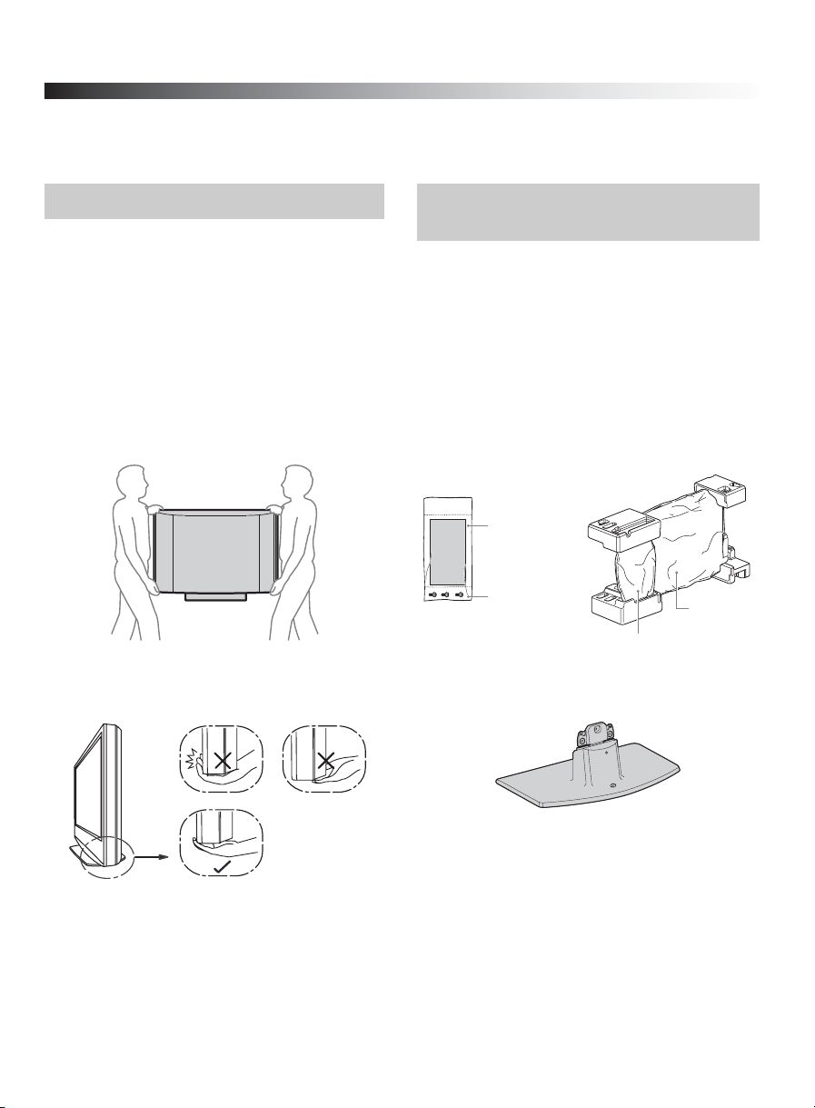
Getting Started
1. Installing the TV
How to Carry the TV Install the Table-Top Stand before
Be sure to follow these guidelines to protect
your property and avoid causing serious injury.
• Before carrying the TV, disconnect all cables.
• Carrying a large size TV requires two or
more people.
• When you carry the TV, place your hand as
illustrated and hold it securely. Do not exert
pressure on the LCD screen.
• When carrying the TV, do not subject it to
shocks or excessive vibration.
connecting the TV
The Table-Top Stand for this product is
packaged separately. Attach the TV unit onto
the Table-Top Stand before performing the
connection and setup.
1 Unpack the Table-Top Stand and get the
three screws from the accessories bag.
~
• Keep the screws away from children.
Accessories
bag
• Place your palm directly underneath the
screen, but make sure you do not exert
pressure on the speakers.
6
Screws
Table-Top Stand
TV
2 Place the Table-Top Stand onto a level and
stable surface.
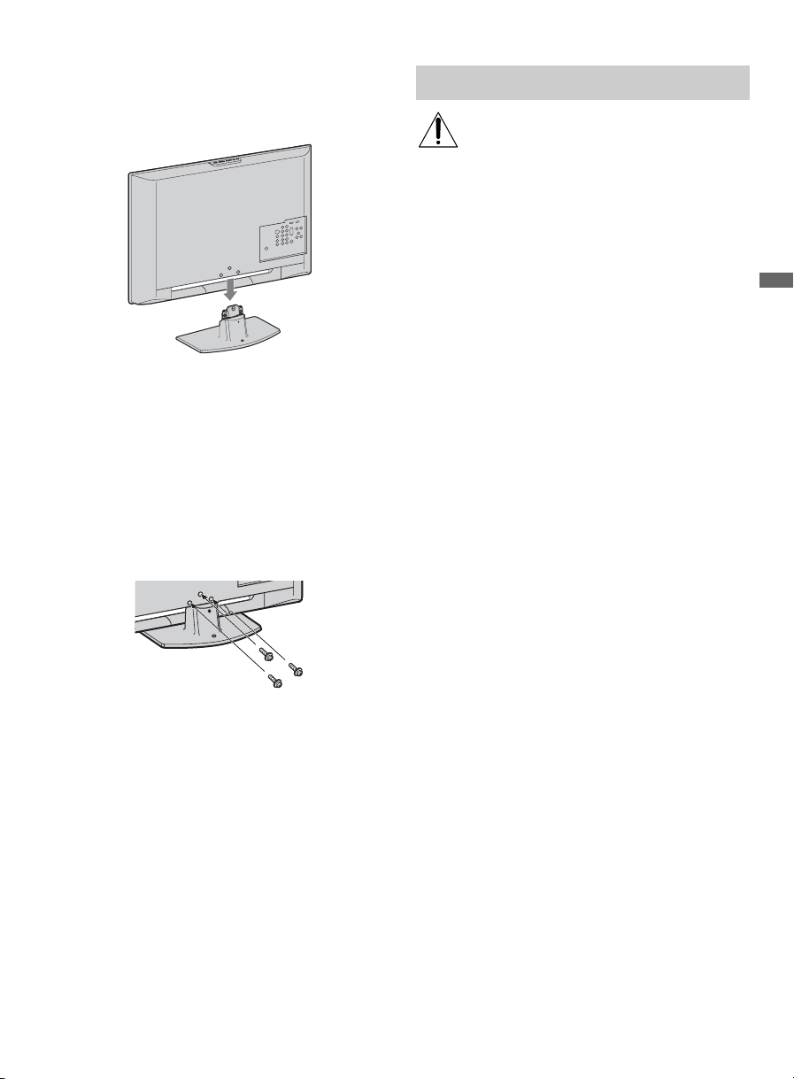
3 Gently slide the TV unit onto the neck of
the Table-Top Stand and align the screw
holes.
~
• When you carry the TV unit, place your hands as
illustrated on page 6 and hold it securely. Do not
exert pressure on the LCD screen or the frame
around the screen.
• Be careful not to pinch your hands or the AC
power cord when attaching the TV unit onto the
Table-Top Stand.
4 Use the supplied screws to attach the TV
unit to the Table-Top Stand.
~
• If you use an electric screwdriver, set the torque
for tightening to approximately 1.5 N·m
{15 Kgf·cm}.
Securing the TV
Sony strongly recommends taking
measures to prevent the TV from
tipping over. Unsecured TVs may
topple and result in property damage,
serious bodily injury or even death.
Prevent the TV from tipping over
s Secure the TV to a wall and/or stand.
s Do not allow children to play or climb on
furniture and TV sets.
s Avoid placing or hanging items on the TV.
s Never install the TV on:
• Slippery, unstable and/or uneven
surfaces.
• Furniture that can easily be used as steps,
such as a chest of drawers.
s Install the TV where it cannot be pulled,
pushed, or knocked over.
s Route all AC power cords and connecting
cables so that they are not accessible to
children.
Use a Sony TV Stand
Use a Sony specified TV stand (see page 2)
and follow the instruction manual provided
with the Sony TV stand.
If a Sony specified TV stand is not used,
consider the following recommended
measures.
Getting Started
(Continued)
7
Recommended Measures to Secure the
TV
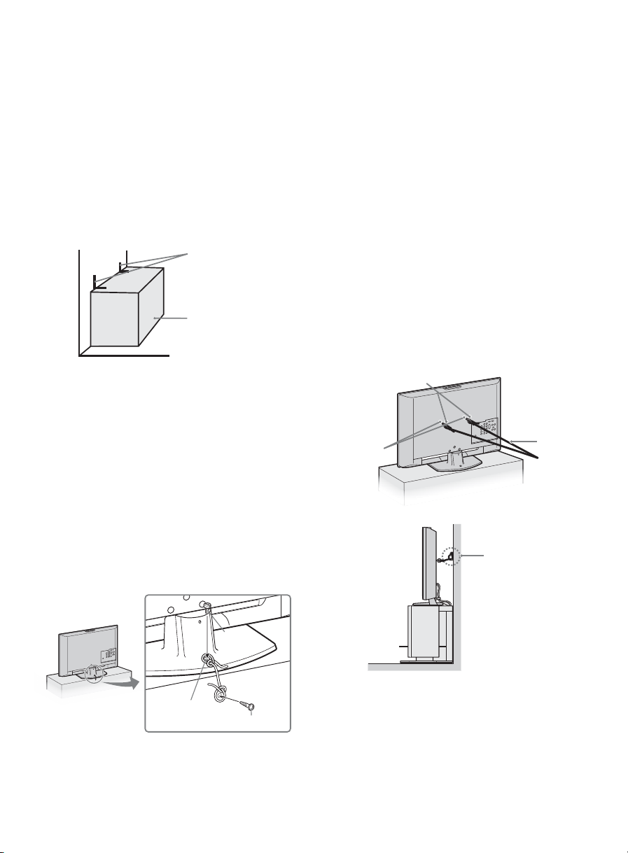
Secure the stand for the TV
Make sure the TV stand can adequately
support the weight of the TV. Use two angle
braces (not supplied) to secure the stand.
For each angle brace use the appropriate
hardware to:
• Attach one side of the angle brace to the
wall stud.
• Attach the other side to the TV stand.
Angle brace
Stand
Secure the TV to the stand
Use the optional hardware listed below (not
supplied):
•M6 × 10-12 mm anchor bolt (screwed into
the TV’s Table-Top stand).
• A screw or similar (attach it to the TV
stand).
• Rope or chain (strong enough to support
the weight of the TV). Make sure that
there is no excess slack in the rope or
chain.
An alternative way to secure the TV is with an
optional Sony Support Belt Kit.
~
• Contact Sony Customer Support to obtain the
optional Support Belt Kit by providing your TV
model name.
For United States call: 1-800-488-7669 or
visit: www.sony.com/accessories
For Canada call: 1-877-899-7669
Attach the TV to the wall
Use the hardware listed below (not supplied):
•Two M6 × 12-18 mm anchor bolts (screw
into the top-most wall-mount holes located
on the rear of the TV).
• Rope or chain (attach to one M6 anchor
bolt).
• Wall-anchor (attach to the wall stud)
strong enough to support the weight of the
TV (pass the rope through the wall-anchor,
then attach to the other M6 anchor bolt).
Anchor bolts
Wall-mount
holes
Wall-anchor
Rope or
chain
Anchor
bolt
~
Screw hole on the
Table-Top stand
Screw
• Attaching the TV to the stand without properly
securing the TV or the stand to the wall will not
ensure that the TV will stay in place. For further
protection, follow all three measures
recommended above.
8
Bundling the Connecting Cables Preparation for Wall-Mounting
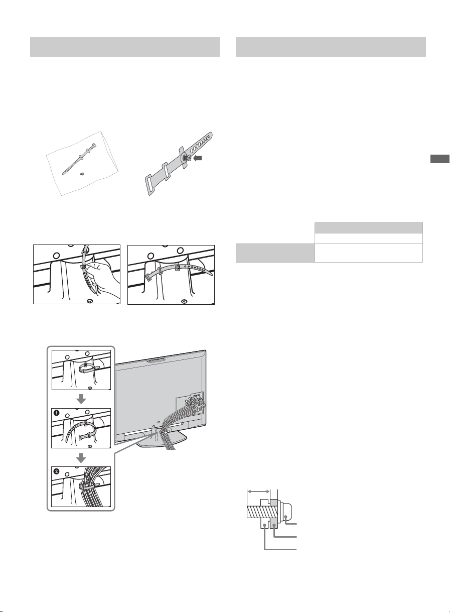
You can bundle the connecting cables as
illustrated below.
1 Get the cable holder from the accessories
bag and place the screw (supplied) in the
cable holder without exerting pressure.
2
Install the cable holder on the Table-Top
Stand by exerting pressure on the screw and
turning it to the left.
3 Secure the connection cables as illustrated
below.
This TV can be installed on a wall by using a
Wall-Mount Bracket (sold separately). Before
mounting the TV on a wall, the Table-Top
Stand must be removed from the TV.
~
• Do not remove the Table-Top Stand for any reason
other than to wall-mount the TV.
• For product protection and safety reasons,
Sony strongly recommends you use the WallMount Bracket model designed for your TV
and the wall-mounting of your TV should be
performed by a Sony dealer or licensed
contractor.
Use your TV with the following wall-mount
bracket only.
Sony TV Model No.
KDL-32L4010
Sony Wall-Mount Bracket
Model No.
SU-WL500
~
• For bracket installation, refer to the instructions on
page 10 and the instruction guide provided by the
Wall-Mount Bracket model for your TV. Sufficient
expertise is required to install this TV, especially to
determine the strength of the wall that will
withstand the TV’s weight.
• Be sure to store the removed screws and Table-Top
Stand in a safe place until you are ready to reattach
the Table-Top Stand. Keep the screws away from
children.
• Be sure to use the screws supplied with the Wall-
Mount Bracket when attaching the mounting
hooks to the TV set.
Supplied screws are designed so they are between
8 to 12 mm in length when measured from the
attaching surface of the mounting hook. The
diameter and length of the screws differ depending
on the Wall-Mount Bracket model. Use of screws
other than those supplied may result in internal
damage to the TV set or cause it to fall.
8-12 mm
Getting Started
~
• Do not bundle the AC power cord with other
connecting cables.
Screw
(supplied with the
Wall-Mount Bracket)
Mounting Hook
Rear of TV
(Continued)
9
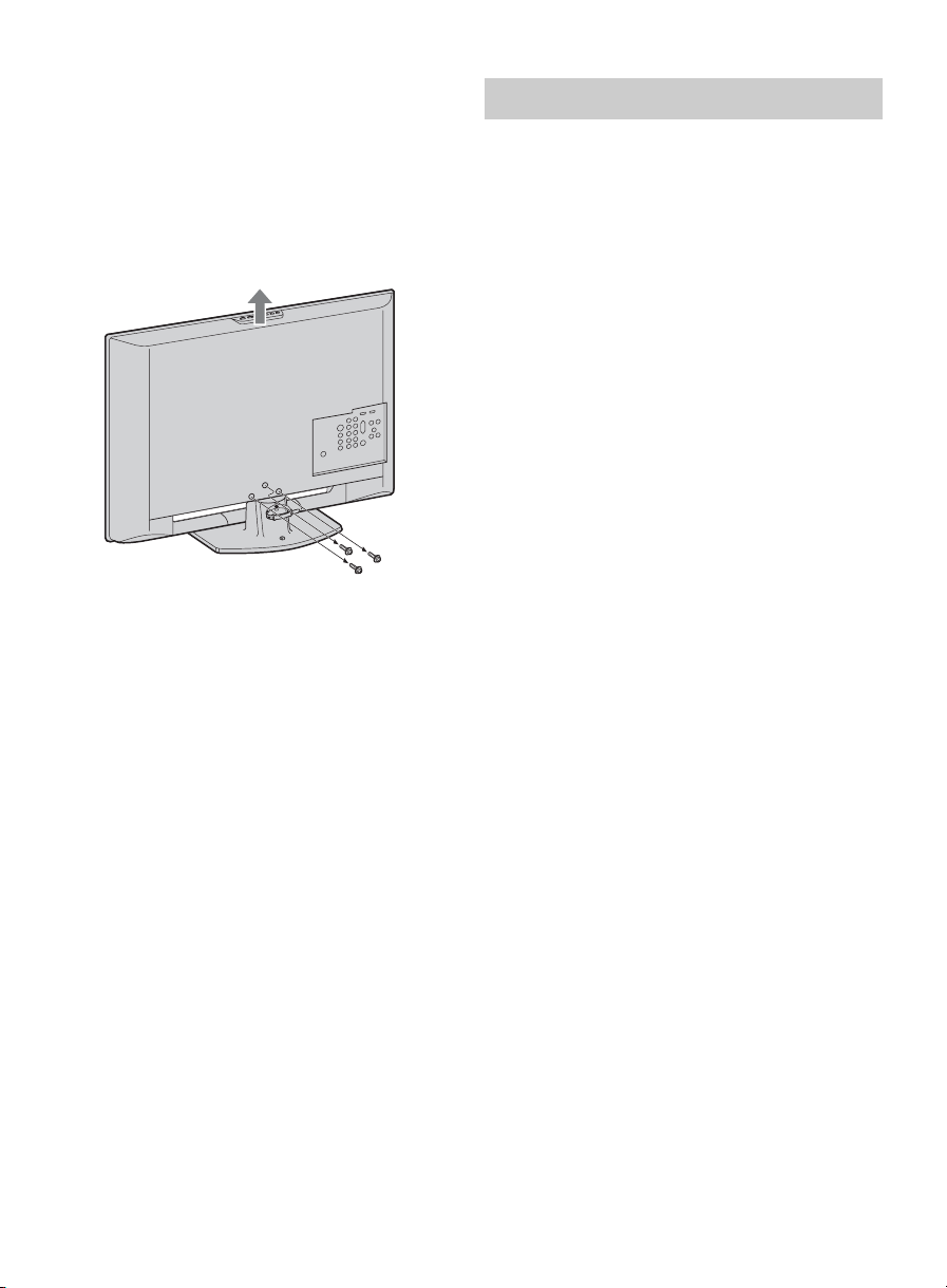
Follow the simple steps below to remove the
Table-Top Stand:
1 Disconnect all the cables from the TV.
2 Remove the four screws as illustrated
below and remove the Table-Top Stand.
Do not remove any other screws from
the TV.
3 Gently lay the TV (face down) onto a level
and stable surface covered with a thick
and soft cloth.
4 Secure the Mounting Hooks to the rear of
the TV. For more details refer to
Installing the Wall-Mount Bracket and
also the instruction guide provided by the
Wall-Mount Bracket model for your TV.
Installing the Wall-Mount Bracket
To Customers
Your TV can be wall-mounted using a WallMount Bracket (sold separately). See table on
page 9 showing the Wall-Mount Bracket
model appropriate for your TV.
For product protection and safety, Sony
strongly recommends that wall-mounting is
performed by a Sony dealer or licensed
contractor. Do not attempt to install it
yourself. Sony is not liable for any damage
or injury caused by mishandling or
improper installation.
Please provide this installation information to
your licensed contractor as well as the
instructions supplied with the Wall-Mount
Bracket.
To Sony Dealers and Licensed
Contractors
To avoid injury and property damage, read
these instructions carefully. Periodic inspection
and maintenance is highly recommended to
ensure that the TV is securely mounted.
10
Installing the Wall-Mount Bracket and
Mounting Hooks
1 Open the Wall-Mount Bracket package
and check for all the required parts
including the instructions.
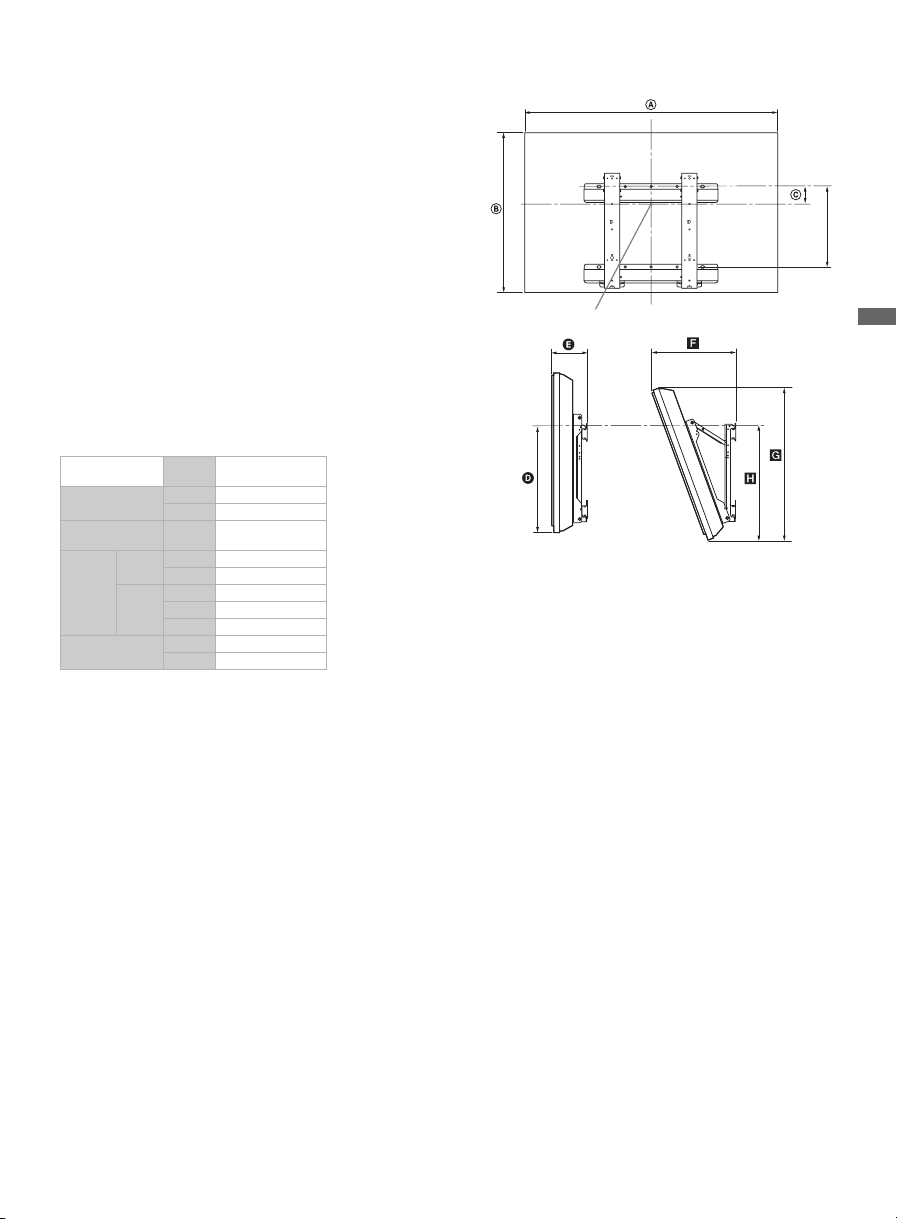
2 See the Installation Dimensions Table
(below) in order to determine the best
location for wall-mounting. The wall must
be strong enough to support at least four
times the weight of the TV. Also refer to
the instructions provided with your WallMount Bracket.
Installation Dimensions Table
TV
Unit: inches (mm)
TV Dimensions
Screen center
dimensions
Length
for each
mounting
angle
Weight
Angle
(0°)
Angle
(20°)
Model
KDL-32L4010
A 31 7/8 (807)
B 21 5/8 (547)
C 6 7/8 (172)
D 12 (302)
E 6 3/8 (159)
F 12 (303)
G 21 (531)
H 20 1/4 (512)
TV 26.5 lb. (12 kg)
×4 106 lb. (48 kg)
~
• The installation dimensions may differ according
to how the TV is installed.
• The wall must be strong enough to support at least
four times the weight of the TV that you are
installing.
Unit: inches (mm)
(320)
8
/
5
12
Center line of the screen when installed on the wall
3 Install the Base Bracket on the wall. Refer
to the instructions provided with your
Wall-Mount Bracket.
4 Disconnect all cables and remove the
Table-Top Stand. See page 10 for more
details.
5 Install Mounting Hooks on the TV. See the
diagram and table on next page for screw
and hook location.
Getting Started
(Continued)
11
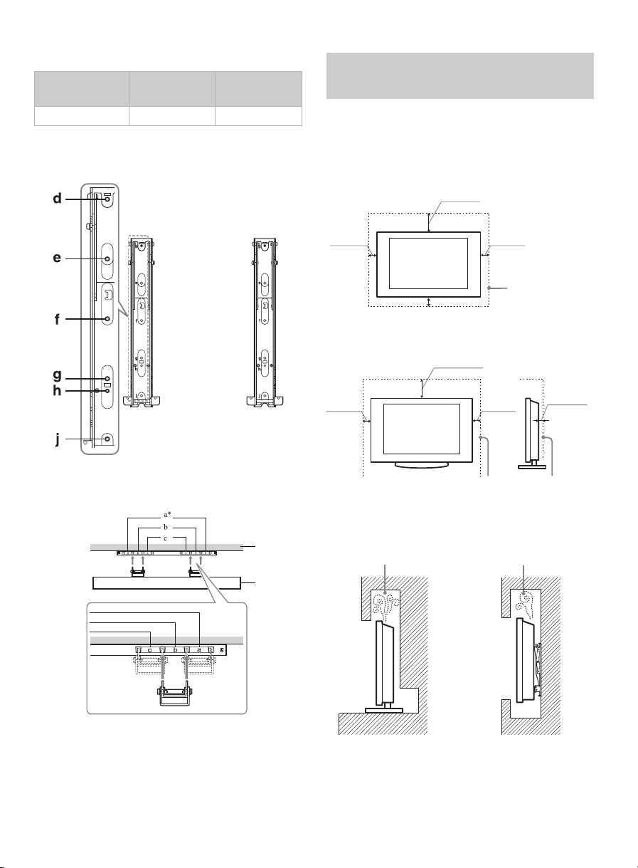
Screw and Hook Location Diagram
TV Model Screw
location
KDL-32L4010 e, g c
Screw location
Hook
location
When installing the Mounting Hook on the TV.
When Installing the TV against a wall or enclosed area
Make sure that your TV has adequate
ventilation. Allow enough space around the
TV as shown below.
When installed on the wall
7
/8
11 inches
(30 cm)
Hook location
When installing the TV onto the Base Bracket.
Wall
TV
4 inches
(10 cm)
4 inches
(10 cm)
Leave at least
this much
4 inches (10 cm)
space around
the TV.
When installed with a stand
7
8
/
11 inches
(30 cm)
4 inches
(10 cm)
4 inches
(10 cm)
2 inches
Leave at least this much space
around the TV.
Never install the TV set as follows:
Air circulation is
blocked.
Wall
Air circulation is
blocked.
3
/
8
(6 cm)
Wall
* Hook position “a” cannot be used for the models
in the table above.
12
~
• Inadequate air circulation can lead to overheating
of the TV. This may cause damage to your TV or
cause a fire.
2. Locating Inputs and Outputs
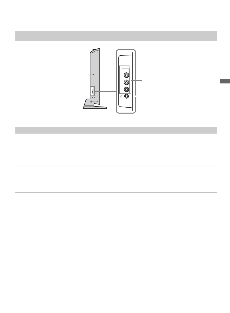
Left side panel
Item Description
1
VIDEO IN 2
VIDEO/
L (MONO)AUDIO-R
2 AUDIO OUT
jack
The composite audio and video output jacks are used to connect external video
devices, such as video cameras, DVDs or video game consoles.
~
• If you have monaural equipment, connect the audio output jack to the L (left)
audio input jack (MONO) of the TV.
Connects to your headphones. If the audio connector does not match the jacks, use
an appropriate audio jack adapter (not supplied).
~
• When the audio is connected, the internal speakers of the TV are turned off.
VIDEO IN
2
VIDEO
L
(MONO)
AUDIO
R
1
Getting Started
2
(Continued)
13
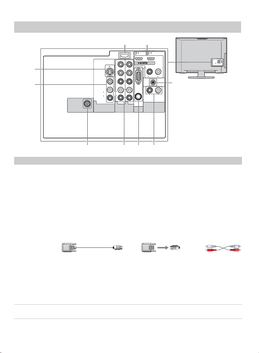
Rear of TV
12
3
4
CABLE / ANTENNA
Item Description
1 HDMI IN 1/2
R-AUDIO-L
HDMI (High definition multimedia interface) offers an audio/video digital interface
without compression between this TV and any other audio/video equipment with
HDMI such as a cable box, a DVD player, a Blu-ray Disc player, a PC, or an
audio/video player. HDMI is compatible with enhanced or high definition video with
digital audio.
~
• If your TV has a DVI rather than an HDMI jack, use a cable or DVI-to-HDMI
adapter to connect the DVI output jack to the HDMI 1 or HDMI 2 input jack. Then,
connect the audio jacks to the AUDIO IN (L/R) jacks, which are located below the
HDMI IN 2 input jack (the DVI connector has been designed for video signals only,
the AUDIO jacks support audio).
SE RV IC E
ON LY
Y
S VIDEO
VIDEO IN PC IN
VIDEO
L
(MONO)
AUDIO
R
B
P
P R
L
AUDIO
R
1 1 2
COMPONENT IN
(1080i/720p/480p/480i)
RGB
AUDIO
7856
2 1
IN
R L
AUDIO
DIGITAL
AUDIO
OUT
(COAXIAL)
L R
(FIX )
A UDIO OUT
9
2 SERVICE
ONLY
14
DVI-to-HDMI cable DVI-to-HDMI adapter Audio cable
~
• The HDMI input jack has been manufactured to comply with audio/video
equipment, such as DVD players with 480i, 480p, 720p and 1080i signals. Signals
generated in a PC can not be converted as expected, due to scaling issues. For a
better picture in your PC use PC IN (RGB IN, PC input). Bear in mind that this TV
displays all video input signals with a resolution of 1,366 × 768 pixels.
This USB port is for service only.
Item Description
3 VIDEO IN 1
S VIDEO
4 VIDEO IN 1
VIDEO/
L (MONO)AUDIO-R
CABLE/
5
ANTENNA
6
COMPONENT
IN 1/2
(1080i/720p/
480p/480i)/
L-AUDIO-R
7 PC IN
(RGB/AUDIO)
Should be connected to the S VIDEO output jack of your DVD player or other video
equipment with S VIDEO. The S VIDEO connection offers a better picture quality
than a composite video connection (4). Because S VIDEO does not provide sound,
the audio cables should remain connected.
Connect the TV to the composite audio and video output jacks of your A/V
equipment, such as a DVD player or other video equipment. On the left side panel of
the TV there is another composite audio/video input jack (VIDEO IN 2).
Input for radio frequency signal used to connect the cable or the VHF/UHF antenna.
Should be connected to the component video jacks (YPBPR) and to the audio jacks
(L/R) of the DVD player or digital cable box. The component video offers a better
picture quality than the S VIDEO (3) or the composite video (4) connections.
Connects to a personal computer’s video output connector using HD15-HD15 cable
(analog RGB, not supplied).
See the “PC Input Signal Reference Chart” on page 18 for information about the
signals that can be displayed.
~
• Some Apple Macintosh computers may require an adapter (not supplied). Connect
the adapter to the computer before connecting the HD15 to HD15 cable.
8 AUDIO OUT
(FIX) R/L
9 DIGITAL
AUDIO OUT
(COAXIAL)
Connect to the left and right audio input jacks of your audio or video equipment. You
can use these outputs to listen to your TV’s audio through your stereo system.
Connects to the optical audio input of a digital audio equipment that is PCM optical
compatible.
Getting Started
~
• The video component connection (YPBPR) or HDMI is necessary to view 480i, 480p, 720p and 1080i
formats. Bear in mind that this TV displays all picture formats with a 1,366 × 768 resolution.
15
 Loading...