

Sony kdl 32bx400 schematic
HISTORY
Model Name: KDL-32/40BX400
SERVICE MANUAL
Click on Page Number to display details of change
Date Part Number Description of Revisions Version
2010.01 9-883-479-01 Original Manual 1.0
2010.10 9-883-479-02 How to reset (OSD Menu errors) (P8) 2.0
2010.12 9-883-479-03
Add Screw Part Number (Base / Stand) (P18)
3.0
SERVICE MANUAL
AZ1-N(5-2) CHASSIS
MODEL DEST
MODEL DEST
KDL-32BX400 AEP / UK KDL-40BX400 AEP / UK
- 1 -
RM-ED022

TABLE OF CONTENTS
Section Title Page Section Title Page
1. GENERAL
Caution ................................................................ 3
Specifications ...................................................... 4
Connectors .......................................................... 7
Self Diagnosis ..................................................... 8
2. DISASSEMBLY
2-1. Rear Cover Removal ............................................. 9
2-2. Stand Assy Removal ............................................. 9
2-3. Speaker Bracket Removal ...................................... 9
2-4. Loudspeaker Removal ........................................... 9
2-5. Under Cover Removal .......................................... 10
2-6. Static Converter Board Removal ........................... 10
2-7. BEN Board Removal ............................................ 10
2-8. H2LS Board Removal ............................................ 10
2-9. HLR Board Removal ............................................. 10
3. SERVICE MENUS
3-1. How to enter the Service Mode .......................... 11
3-2. Service Menu Structure ...................................... 11
3-2-1. Service General Menu .................................. 11
3-2-2. White Balance Adjustment ........................... 11
3-2-3. OSD Service Menu ...................................... 12
3-2-4. Country Selection ......................................... 12
3-2-5. Factory Reset ............................................... 12
3-3. TT Mode ............................................................. 13
4. DIAGRAMS
4-1. Block Diagram ................................................... 14
4-2. Circuit Board Location ....................................... 15
5. EXPLODED VIEWS
5-1. Chassis ................................................................ 16
5-2. Bezel Assy & Stand Assy .................................... 18
5-3. Rear Cover Assy & Power Supply Cords ........... 19
6. PARTS LIST
............................................................... . 20
WARNING !!
AN ISOLATION TRANSFORMER SHOULD BE USED DURING ANY
SERVICE WORK TO AVOID POSSIBLE SHOCK HAZARD DUE TO
LIVE CHASSIS, THE CHASSIS OF THIS RECEIVER IS DIRECTLY
CONNECTED TO THE POWER LINE.
SAFETY-RELATED COMPONENT WARNING !!
COMPONENTS IDENTIFIED BY SHADING AND MARKED ON
THE EXPLODED VIEWS AND IN THE PARTS LIST ARE CRITICAL
FOR SAFE OPERATION. REPLACE THESE COMPONENTS WITH
SONY PARTS WHOSE PART NUMBERS APPEAR AS SHOWN IN
THIS MANUAL OR IN SUPPLEMENTS PUBLISHED BY SONY.
- 2 -
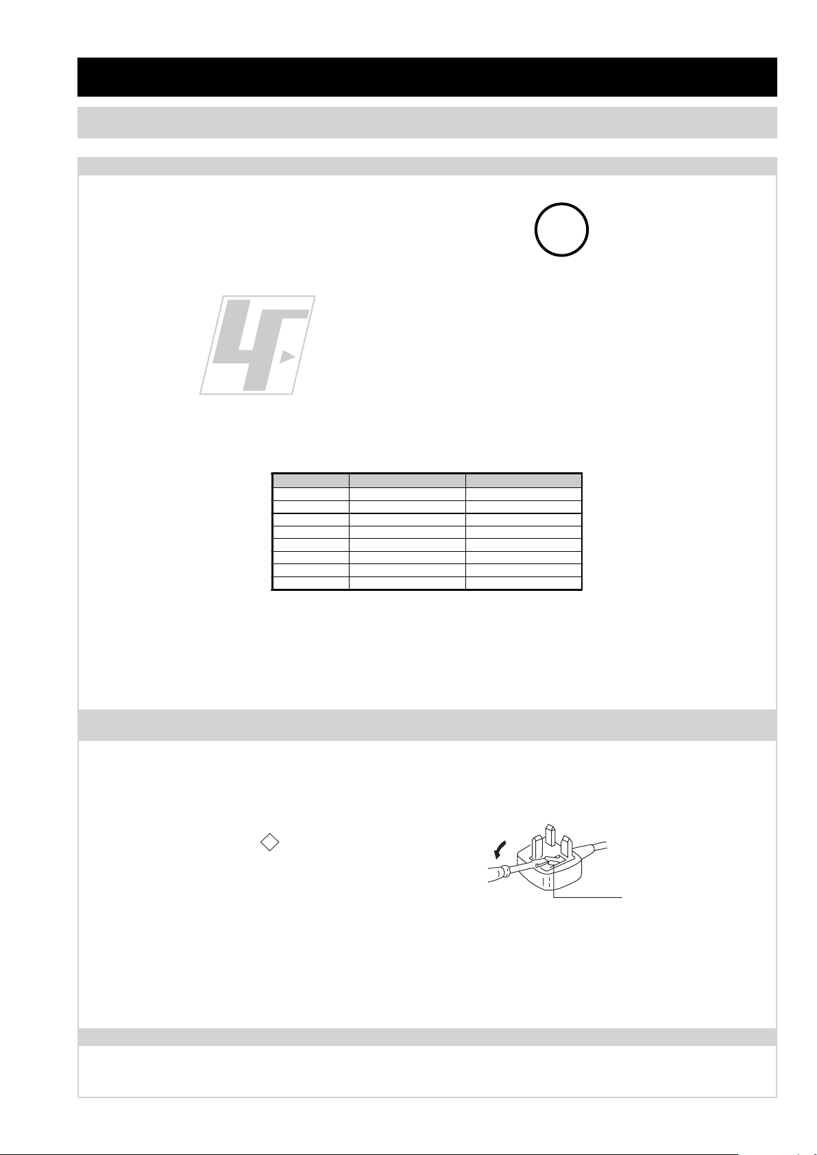
Partnumber Diameter Remarks
7-640-005-19 0.3mm 0.25Kg
7-640-005-20 0.4mm 0.50Kg
7-640-005-21 0.5mm 0.50Kg
7-640-005-22 0.6mm 0.25Kg
7-640-005-23 0.8mm 1.00Kg
7-640-005-24 1.0mm 1.00Kg
7-640-005-25 1.2mm 1.00Kg
7-640-005-26 1.6mm 1.00Kg
SECTION 1 GENERAL
How to replace the fuse.
Open the fuse compartment with
a screwdriver blade and replace
the fuse.
FUSE
ASA
T
mark.
SECTION 1 GENERAL
CAUTION
Lead Free Soldered Boards
example
The circuit boards used in these models have been processed using
Lead Free Solder. The boards are identified by the LF logo located
close to the board designation e.g. H1 etc [ see example ]. The
servicing of these boards requires special precautions to be taken as
outlined below.
Lead Free Solder material must be used to comply with environmental requirements of new solder joints. Lead Free Solder is available
under the following part numbers :
Due to the higher melting point of Lead Free Solder the soldering iron tip temperature needs to be set to 370 degrees centigrade. This
requires soldering equipment capable of accurate temperature control coupled with a good heat recovery characteristics.
For more information on the use of Lead Free Solder, please refer to http://www.sony-training.com
UK PLUG WARNING
WARNING (UK Models only)
The flexible mains lead is supplied connected to a B.S. 1363 fused
plug having a fuse of the correct rating for the set. Should the fuse
need to be replaced, use a fuse of the same rating approved by ASTA
to BS 1362, ie one that carries the
IF THE PLUG SUPPLIED WITH THIS APPLIANCE IS NOT SUITABLE
FOR THE OUTLET SOCKETS IN YOUR HOME, IT SHOULD BE CUT
OFF AND AN APPROPRIATE PLUG FITTED. THE PLUG SEVERED
FROM THE MAINS LEAD MUST BE DESTROYED AS A PLUG WITH
BARED WIRES IS DANGEROUS IF ENGAGED IN A LIVE SOCKET.
When an alternative type of plug is used, it should be fitted with the
correct rating fuse, otherwise the circuit should be protected by the
same rating fuse at the distribution board.
mark.
LCD PANEL CAUTION
Whilst working on this product, it is not recommended to lay the TV set face down when powered up, as this can result in panel problems.
If it is necessary to power up the TV set when face down, the time should be minimised as much as possible.
- 3 -
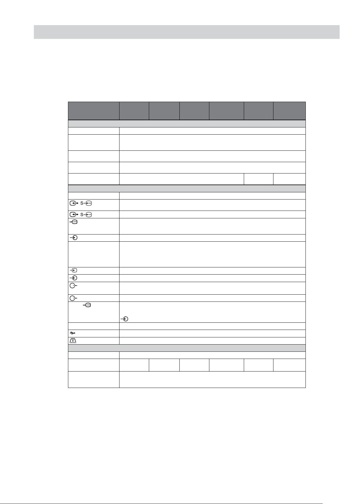
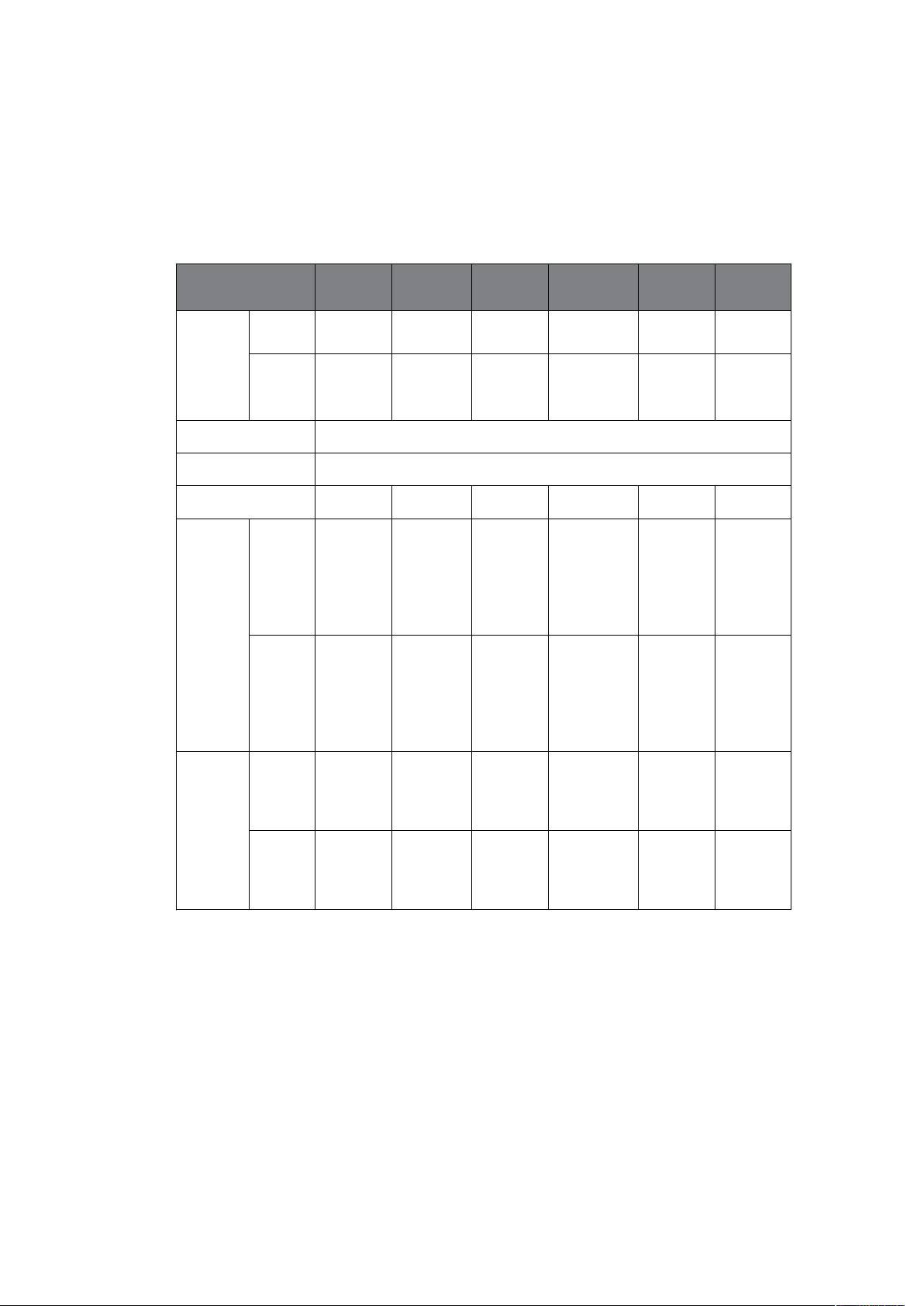
SPECIFICATIONS
Model name KDL-
46EX4xx
KDL-40BX4/
EX4/NX5xx
KDL37EX4xx
KDL-32BX3/
BX4/EX3/EX4/
NX5xx
KDL26EX3xx
KDL22EX3xx
System
Panel System
LCD (Liquid Crystal Display) Panel
TV System
Depending on your country/region selection
Analogue: B/G/H, D/K, L, I
Digital: DVB-T, DVB-C
Colour/Video System
Analogue: PAL, PAL60 (only video input), SECAM, NTSC3.58, NTSC4.43 (only video input)
Digital: MPEG-2 MP@ML/HL, H.264/MPEG-4 AVC HP@L4.0, MP@L3.0
Channel Coverage
Analogue: 46.25 - 855.25 MHz
Digital: VHF/UHF
Sound Output
10 W + 10 W (RMS) 8 W + 8 W
(RMS)
5 W + 5 W
(RMS)
Input/Output jacks
Aerial
75 ohm external terminal for VHF/UHF
/ AV1*
1
21-pin scart connector including audio/video input, RGB input, S-Video input, and Analogue TV audio/video
output.
/ AV2*
2
21-pin scart connector including audio/video input, RGB input, S-Video input, and audio/video output.
COMPONENT IN
Supported formats: 1080p, 1080i, 720p, 576p, 576i, 480p, 480i
Y: 1 Vp-p, 75 ohms, 0.3V negative sync/P
B/CB
: 0.7 Vp-p, 75 ohms/
P
R/CR
: 0.7 Vp-p, 75 ohms
COMPONENT IN
Audio input (phono jacks)
HDMI IN 1, 2, 3, 4
Video: 1080p, 1080p24, 1080i, 720p, 576p, 576i, 480p, 480i
Audio: Two channel linear PCM
32, 44.1 and 48 kHz, 16, 20 and 24 bits, Dolby Digital
PC (see page 6)
Analogue audio (minijack) (HDMI 1 only)
AV3
Video input (phono jack)
AV3
Audio input (phono jacks)
DIGITAL AUDIO
OUT (OPTICAL)
Digital optical jack (Two channel linear PCM, Dolby Digital)
Audio output (Left/Right) (phono jacks)
PC IN
PC Input (15 Dsub) (see page 6)
G: 0.7 Vp-p, 75 ohms, non Sync on Green/B: 0.7 Vp-p, 75 ohms/
R: 0.7 Vp-p, 75 ohms, H/V Sync: TTL level
PC audio input (minijack)
i
Headphones jack
USB port
CAM (Conditional Access Module) slot
Power and others
Power Requirements
220–240 V AC, 50 Hz
Screen Size (measured
diagonally)
46 inches /
Approx. 117 cm
40 inches /
Approx. 102 cm
37 inches /
Approx. 94 cm
32 inches / Approx.
81 cm
26 inches /
Approx. 66 cm
22 inches /
Approx. 55 cm
Display Resolution
1,920 dots (horizontal) × 1,080 lines (vertical) (KDL-46EX4xx, KDL-40BX4/EX4/NX5xx, KDL-37EX4xx,
KDL-32BX4/EX4/NX5xx)
1,366 dots (horizontal) × 768 lines (vertical) (KDL-32BX3/EX3xx, KDL-26EX3xx, KDL-22EX3xx)
- 4 -
*1AV1 outputs available only for analogue TV.
*
2
AV2 outputs watching screen (except PC, HDMI, Component, USB).
*
3
Specied standby power is reached after the TV nishes necessary internal processes.
*
4
4 hours a day and 365 days a year.
Design and specications are subject to change without notice.
Power
consumption
in “Home”/
“Standard”
mode
142 W 110 W 95 W 74 W 52 W 39 W
in “Shop”/
“Vivid”
mode
183 W 144 W (KDL-
40NX5xx)
146 W (KDL40EX4/BX4xx)
120 W 93 W (KDL-
32BX4/EX4/
NX5xx)
94 W (KDL32BX3/EX3xx)
62 W 46 W
Standby Power
Consumption*
3
0.19 W
O mode Power
Consumption
0.18 W
Average anual energy
consumption*
4
207 kWh 161 kWh 139 kWh 108 kWh 76 kWh 57 kWh
Dimensions
(w × h × d)
(with stand)
112.7 x 71.1 x
29.4 cm
102.3 x 66.5 x
31.0 cm (KDL40NX5xx)
99.6 x 63.5 x 25.0
cm (KDL40BX4xx)
99.2 x 63.5 x 25.0
cm (KDL40EX4xx)
92.1 x 59.9 x
25.1 cm
82.5 x 55.4 x 26.0
cm (KDL32NX5xx)
80.4 x 53.2 x 22.0
cm (KDL-32BX3/
BX4xx)
80.0 x 53.2 x 22.0
cm (KDL-32EX3/
EX4xx)
67.2 x 45.9 x
22.0 cm
55.1 x 40.2 x
21.5 cm
(without
stand)
112.7 x 67.4 x
10.2 cm
102.3 x 62.8 x
10.0 cm (KDL40NX5xx)
99.6 x 59.8 x 9.9
cm (KDL40BX4xx)
99.2 x 59.8 x 10.0
cm (KDL40EX4xx)
92.1 x 56.4 x 9.8 cm82.5 x 51.7 x 10.2
cm (KDL32NX5xx)
80.4 x 49.7 x 9.6 cm
(KDL-32BX3/
BX4xx)
80.0 x 49.7 x 9.7 cm
(KDL-32EX3/
EX4xx)
67.2 x 42.3 x 9.9 cm55.1 x 36.7 x 8.2
cm
Mass (with stand)
20.4 kg 22.4 kg (KDL40NX5xx)
15.6 kg (KDL40BX4xx)
15.9 kg (KDL40EX4xx)
13.6 kg 15.5 kg (KDL32NX5xx)
10.7 kg (KDL32BX3/BX4xx)
11.0 kg (KDL32EX3/EX4xx)
8.8 kg 6.6 kg
(without
stand)
18.1 kg 19.2 kg (KDL40NX5xx)
13.6 kg (KDL40BX4xx)
13.9 kg (KDL40EX4xx)
11.6 kg 13.0 kg (KDL32NX5xx)
9.2 kg (KDL32BX3/BX4xx)
9.5 kg (KDL32EX3/EX4xx)
7.3 kg 6.0 kg
Model name KDL-
46EX4xx
KDL-40BX4/
EX4/NX5xx
KDL37EX4xx
KDL-32BX3/
BX4/EX3/EX4/
NX5xx
KDL26EX3xx
KDL22EX3xx
- 5 -
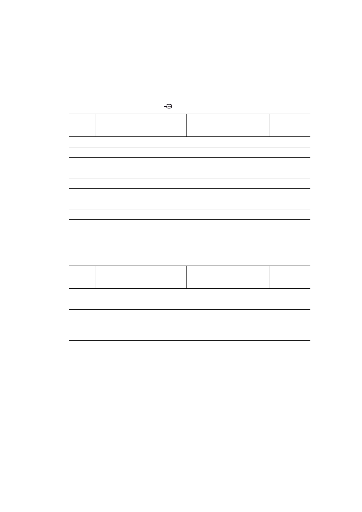
PC Input Signal Reference Chart for PC IN
• This TV’s PC input does not support Sync on Green or Composite Sync.
• This TV’s PC input does not support interlaced signals.
• This TV’s PC input supports signals in the above chart with a 60 Hz vertical frequency.
PC Input Signal Reference Chart for HDMI IN 1, 2, 3 and 4
Signals Horizontal (Pixel) Vertical (Line)
Horizontal
frequency
(kHz)
Vertical
frequency (Hz)
Standard
VGA 640 480 31.5 60 VGA
SVGA 800 600 37.9 60 VESA Guidelines
XGA 1024 768 48.4 60 VESA Guidelines
WXGA 1280 768 47.4 60 VESA
WXGA 1280 768 47.8 60 VESA
WXGA 1360 768 47.7 60 VESA
SXGA 1280 1024 64 60 VESA
UXGA 1600 1200 75 60 VESA
HDTV 1920 1080 67.5 60 EIA
Signals Horizontal (Pixel) Vertical (Line)
Horizontal
frequency
(kHz)
Vertical
frequency (Hz)
Standard
VGA 640 480 31.5 60 VGA
SVGA 800 600 37.9 60 VESA Guidelines
XGA 1024 768 48.4 60 VESA Guidelines
WXGA 1280 768 47.4 60 VESA
WXGA 1280 768 47.8 60 VESA
WXGA 1360 768 47.7 60 VESA
SXGA 1280 1024 64 60 VESA
- 6 -
 Loading...