

Page 1

Self Diagnosis
HISTORY INFORMATION FOR THE FOLLOWING MANUAL:
Supported model
SERVICE / TRAINING MANUAL
AZ3TK Chassis
ORIGINAL MANUAL ISSUE DATE: 3/2012
Version Date Subject
1.0 3/23/2012 Original Manual Release Date
Segment: P-2F
LCD Digital Color TV
9-883-879-01
Page 2

Self Diagnosis
Supported model
SERVICE / TRAINING MANUAL
AZ3TK Chassis
Segment: P-2F
KDL-40BX455
LCD Digital Color TV
9-883-879-01
Page 3

MODEL LIST
MODEL COMMANDER DESTINATION MODEL COMMANDER DESTINATION
KDL-32BX355 RM-YD081 BRAZIL KDL-40BX455 RM-YD081 BRAZIL
KDL-46BX455 RM-YD081 BRAZIL
9-883-879-01
Page 4
TABLE OF CONTENTS
Cautions and Warnings ...................................................................................ii
Section 1 - Features and Overview ................................................................1
Features ........................................................................................................1
Specications ................................................................................................1
Chassis Overview .......................................................................................... 3
Overall Circuit Description ............................................................................. 5
Main Board ...............................................................................................5
Power Supply Board ................................................................................. 5
IR Board .................................................................................................... 5
Switch Unit ................................................................................................ 5
LCD Panel Assembly ................................................................................6
Section 2 - Troubleshooting ...........................................................................7
Overview .......................................................................................................7
Updating the Software ..............................................................................7
Self Diagnosis Function ................................................................................. 7
Standby LED Blink Count .........................................................................7
Viewing the Self Check Diagnosis History ................................................ 8
Triage Chart .................................................................................................10
Section 3 - Flow Charts and Diagrams ........................................................ 11
Block Diagram ............................................................................................. 11
No Power ................................................................................................ 12
Standby LED Blinking ............................................................................. 13
No Video .................................................................................................14
Section 4 - Disassembly/Part Number Information ....................................16
Table-Top Stand and Rear Cover Removal .................................................16
Main Board (A) and Power Supply Board (G) Removal .............................. 17
LCD Panel Removal .................................................................................... 18
Cleaning the LCD Panel .........................................................................18
Connectors ..................................................................................................19
Screws ......................................................................................................... 19
Accessories and Packaging ........................................................................20
Wire Dressing .............................................................................................. 21
Section 5 - Updates and Adjustments .........................................................22
Overview .....................................................................................................22
Software Updates for Customers ................................................................22
Software Updates for Servicers ................................................................... 22
Software Update Responsibility .............................................................. 23
Checking the Software Version ...............................................................23
Examples of Software Correctable Symptoms .......................................23
Accessing Service Adjustment Mode ..........................................................24
Completing Service Requirements
When Replacing the Main Board ................................................................. 24
Viewing the Status Information ...............................................................25
Adding the Serial Number ....................................................................... 25
Selecting the Model Name ...................................................................... 26
Completing Service Requirements
When Replacing the LCD Panel .................................................................. 26
Viewing the Status Information ...............................................................27
Changing the LVDS Spectrum ................................................................ 27
Selecting the LCD Panel ........................................................................ 27
Verify before proceeding to the next step: ..............................................27
Optional Service Adjustments .....................................................................28
Adjusting the Sound ................................................................................ 28
Wide Band Tuning Adjustments .............................................................. 29
Range Scan Adjustments .......................................................................29
APPENDIX A: ENCRYPTION KEY COMPONENTS .................................... A-1
KDL-32BX355/40BX455/46BX455 i
Page 5
CAUTIONS AND WARNINGS
CAUTION
These servicing instructions are for use by qualied service personnel only.
To reduce the risk of electric shock, do not perform any servicing other than
that contained in the operating instructions unless you are qualied to do so.
WARNING!!
An isolation transformer should be used during any service to avoid possible
shock hazard, in case of live chassis.
!
SAFETY-RELATED COMPONENT WARNING!!
There are critical components used in LCD color TVs that are important for
safety. These components are identied with shading and
schematic diagrams and the parts list. It is essential that these critical parts
be replaced only with the part number specied in the parts list to prevent
electric shock, re, or other hazard.
!
mark on the
NOTE: Do not modify the original design without obtaining written permission
from the manufacturer or you will void the original parts and labor warranty.
KDL-32BX355/40BX455/46BX455 ii
Page 6
CAUTIONS AND WARNINGS
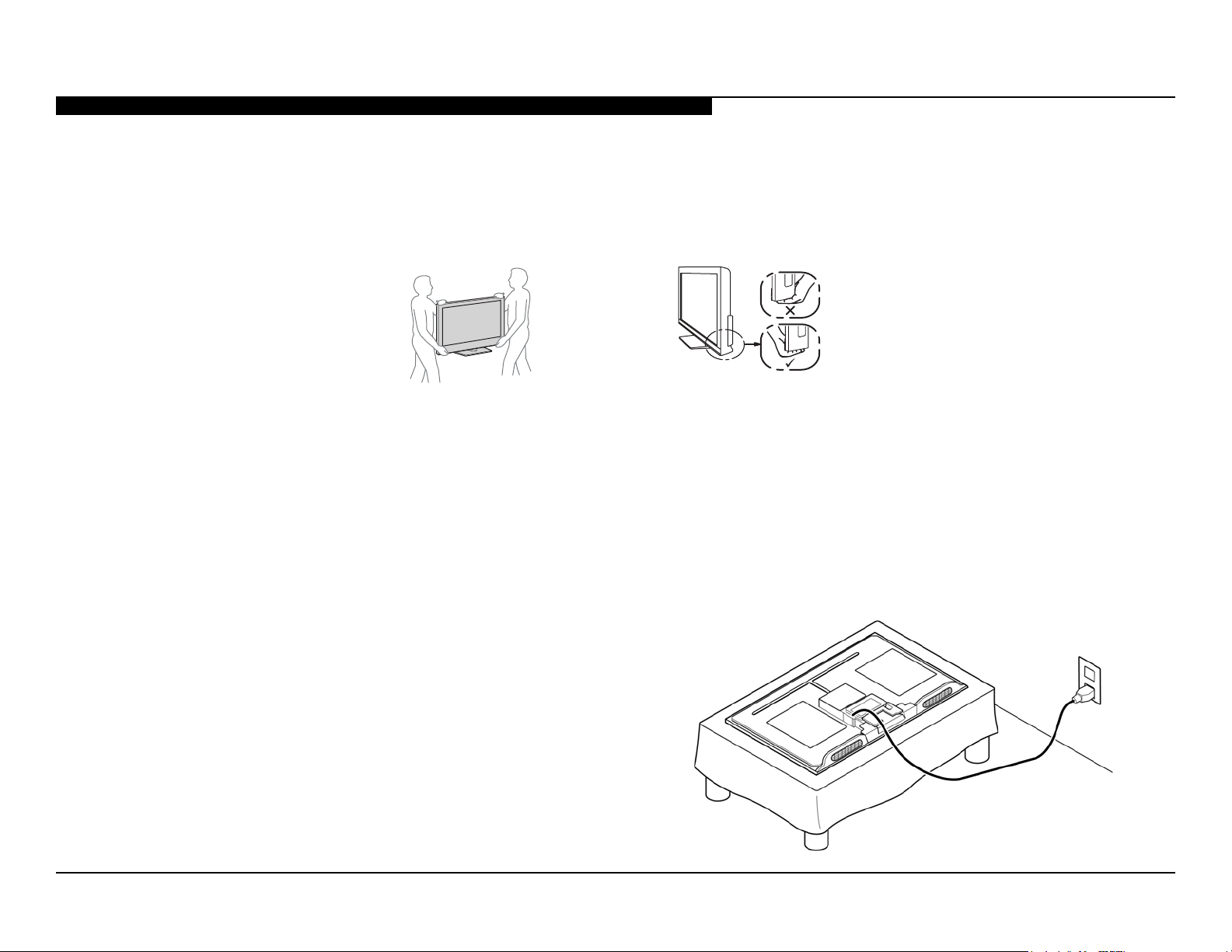
SETTING UP AND CARRYING THE TV
● Disconnect all cables when carrying the TV.
● Carry the TV with the adequate number of people; larger size TVs require two or more people.
● Correct hand placement while carrying the TV is very important for safety and to avoid damage.
USE CAUTION WHEN HANDLING THE LCD PANEL
When repairing the LCD panel, be sure you are grounded by using a wrist band.
When installing the LCD panel on a wall, the LCD panel must be secured using the 4 mounting holes on the rear cover.
1. Do not press on the panel or frame edge to avoid the risk of electric shock.
2. Do not scratch or press on the panel with any sharp objects.
3. Do not leave the module in high temperatures or in areas of high humidity for an extended period of time.
4. Do not expose the LCD panel to direct sunlight.
5. Avoid contact with water. It may cause a short circuit within the module.
6. Disconnect the AC power when replacing the backlight or inverter circuit.
(High voltage occurs at the inverter circuit at 650Vrms.)
7. Always clean the LCD panel with a soft cloth material.
8. Use care when handling the wires or connectors of the inverter
circuit. Damaging the wires may cause a short.
9. Protect the panel from ESD to avoid damaging the electronic
circuit (C-MOS).
10. During the repair, DO NOT leave the Power On for more than
1 hour while the TV is face down on a cloth.
KDL-32BX355/40BX455/46BX455 iii
Page 7
CAUTIONS AND WARNINGS
CLEANING THE LCD PANEL
CAUTION: When cleaning the TV, be sure to unplug the power cord to avoid any chance of electric shock.
Clean the cabinet of the TV with a dry soft cloth.
Wipe the LCD screen gently with a soft cloth.
; Stubborn stains may be removed with a cloth slightly moistened with a solution of mild soap and warm water.
; If using a chemically pretreated cloth, please follow the instruction provided on the package.
; Never use strong solvents such as a thinner, alcohol or benzine for cleaning.
; Periodic vacuuming of the ventilation openings is recommended to ensure proper ventilation.
; Do Not use paper towels, any type of abrasive pad, rags, rubber or vinyl materials to clean the screen. Using these materials could easily scratch the
screen which may result in permanent damage.
; Do Not use any cleaning product containing alkaline/acid cleaner, scouring powder, or volatile solvent, such as alcohol, ammonia, benzine, thinner or
insecticide. Using any of these harsh cleaners may result in permanent damage to the screen.
; Do Not spray water or detergent directly onto the TV screen . If liquid drips into the bottom of the screen it may cause a failure.
KDL-32BX355/40BX455/46BX455 iv
Page 8
CAUTIONS AND WARNINGS
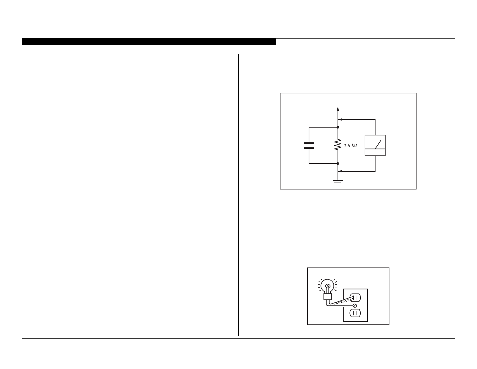
To Exposed Metal
Parts on Set
0.15 µF
Earth Ground
AC
Voltmete
r
(0.75V)
Trouble Light
SAFETY CHECK-OUT
After correcting the original service problem, perform the following safety
checks before releasing the set to the customer:
1. Check the area of your repair for unsoldered or poorly soldered
connections. Check the entire board surface for solder splashes
and bridges.
2. Check the interboard wiring to ensure that no wires are “pinched” or
touching high-wattage resistors.
3. Check that all control knobs, shields, covers, ground straps, and
mounting hardware have been replaced. Be absolutely certain that
you have replaced all the insulators.
4. Look for unauthorized replacement parts, particularly transistors,
that were installed during a previous repair. Point them out to the
customer and recommend their replacement.
5. Look for parts which, though functioning, show obvious signs of
deterioration. Point them out to the customer and recommend their
replacement.
6. Check the line cords for cracks and abrasion. Recommend the
replacement of any such line cord to the customer.
7. Check the antenna terminals, metal trim, “metallized” knobs,
screws, and all other exposed metal parts for AC leakage. Check
leakage as described in “Leakage Test”.
The AC leakage from any exposed metal part to earth ground and from all
exposed metal parts to any exposed metal part having a return to chassis,
must not exceed 0.5 mA (500 microamperes). Leakage current can be
measured by any one of three methods.
1. A commercial leakage tester.
Follow the manufacturers’ instructions provided with the tester.
2. A battery-operated AC milliammeter.
LEAKAGE TEST
3. Measuring the voltage drop across a resistor by means of a VOM
or battery-operated AC voltmeter. The “limit” indication is 0.75 V, so
analog meters must have an accurate low voltage scale. Nearly all
battery-operated digital multimeters that have a 2 VAC range are
suitable. (see Figure A)
Figure A. Use an AC voltmeter to check AC leakage.
HOW TO FIND A GOOD EARTH GROUND
The cover-plate retaining screw on most AC outlet boxes is at earth ground.
Verify the AC outlet box retaining screw ground by connecting a 60W to
100W incandescent (not a neon or uorescent lamp) between the hot side of
the receptacle and the retaining screw. Try both slots, if necessary, to locate
the hot side on the line; the lamp should light at normal brilliance if the screw
is at ground potential. (see Figure B)
AC Outlet Box
Figure B. Checking for earth ground.
KDL-32BX355/40BX455/46BX455 v
Page 9
SECTION 1 - FEATURES AND OVERVIEW
FEATURES
The AZ3TK chassis is one of several designs for the 2012 model line of
Sony Bravia® LCD televisions. This manual covers the following models:
KDL-32BX355
KDL-40BX455
KDL-46BX455
The BRAVIA® Sync™ BX series LED LCD HDTV
● Brilliant Full HD (1080p) picture quality
● Four HD inputs for a cable box, PS3™ and more1
● Share your pictures on the big screen via USB input
● Crisp detail & contrast w/ Clear Resolution Enhancer
● Optimized picture based on what you’re watching
● Less grain & a clear picture w/ Digital Noise Reduction
● Theater-like movie viewing with 24p True Cinema
● One remote for multiple devices with BRAVIA® Sync™2
SPECIFICATIONS
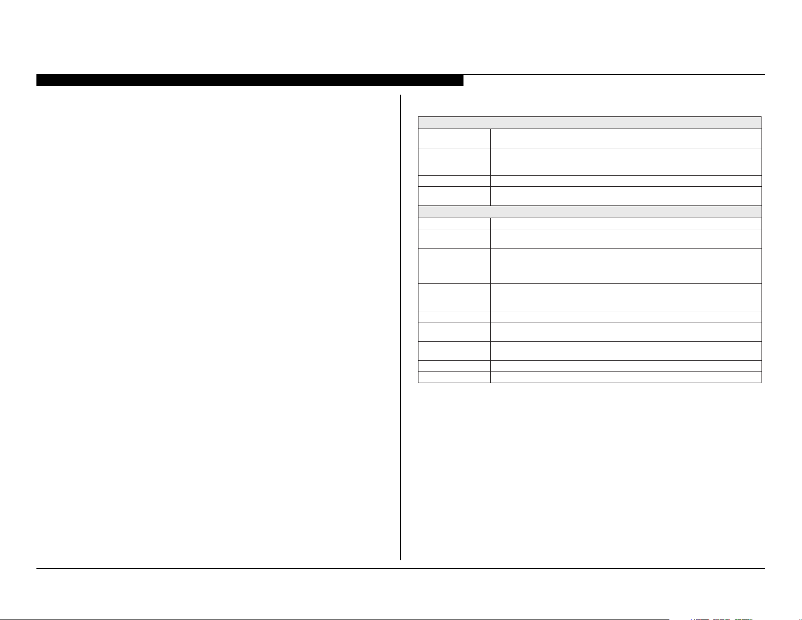
Sistema
Sistema de televisã Analógico: NTSC/PAL-M/PAL-N
Cobertura de cana VHF: 2-13
Sistema do Painel Painel LCD (Tela de Cristal Líquido)
Potência de saída dos
Alto-falantes (RMS)
Entradas/Saídas
CABLE/ANTENNA
VIDEO IN 1/2
COMPONENT IN
HDMI IN 1/2
AUDIO OUT
DIGITAL AUDIO OUT
(OPTICAL)
NI CP ovitisop ,smho 57 ,p-pV 7,0 ,BGR ocigólana ,nip-51 bus-D
PC/HDMI IN 1 AUDIO IN
BSU Foto, Música e Vídeo
*1Distorcão Harmônica Total.
Digital: SBTVD-T
UHF: 14-69
CATV: 1-135
8 W + 8 W (127 V CA, THD*
500 mVrms.)
Terminal externo de 75 ohms para entradas RF
VÍDEO: 1 Vp-p, 75 ohms não balanceados, sincronizacão negativa
ÁUDIO: 500 mVrms (Típico) / Impedância: 47 Kohms
YPBPR (Vídeo componente): Y: 1,0 Vp-p, 75 ohms não balanceado, sincronizacão negativa /
P
B
: 0,7 Vp-p, 75 ohms
P
R
: 0,7 Vp-p, 75 ohms / Formato do sinal: 480i, 480p, 576i, 576p, 720p, 1080i, 1080p
ÁUDIO: 500 mVrms (Típico) / Impedância: 47 Kohms
HDMI:Vídeo: 480i, 480p, 576i, 576p, 720p, 1080i, 1080p, 1080/24p
Áudio: Dois canais lineares PCM 32, 44,1 e 48 kHz, 16, 20 e 24bits, Dolby Digital
Entrada do PC
Saída de áudio, Fones de ouvido (minitomada)
Sinal óptico PCM/Dolby Digital
Consulte o Capítulo de Referência de Sinal de Entrada do PC e HDMI IN
Minitomada estéreo, 500 mVrms, (Típico) / Impedância: 47 Kohms
1
10% sinal 1 KHz, Alto-falante de 8 Ohms, Nível de entrada
1. Cables sold separately.
2. Syncs with BRAVIA® Sync or Theatre Sync™ products.
KDL-32BX355/40BX455/46BX455 1
Page 10
SECTION 1 - FEATURES AND OVERVIEW
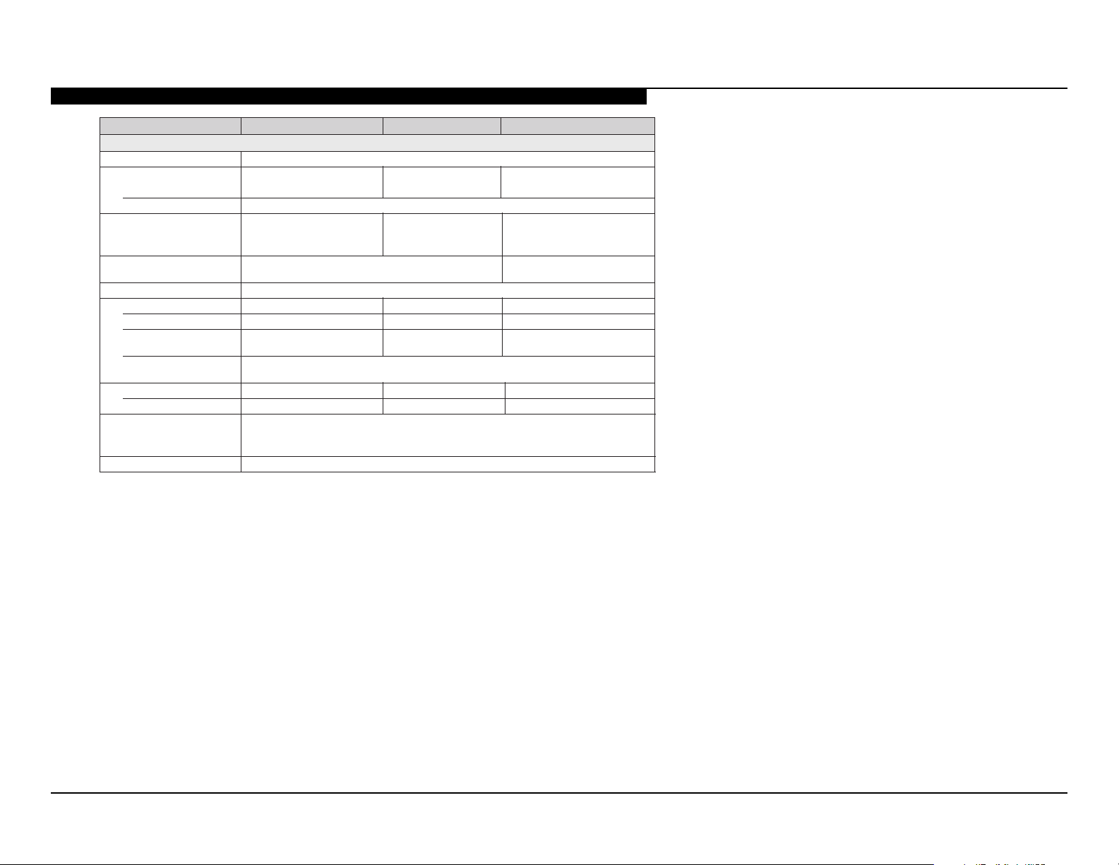
Nome do modelo KDL-46BX455 KDL-40BX455 KDL-32BX355
Energia e outros
Requisito de energia110-220 V CA, 60 Hz
Consumo de energia
em uso
em modo de esperaMenos do que 1 W
Tamanho da tela(cm)Aprox. 116,8 Aprox. 101,6 Aprox. 80,0
(polegadas m edidas
diagonalmente)
Resolucão da tela 1.920 pontos (horizontal) × 1.080 linhas (vertical) 1.366 pontos (horizontal) ×
001 × 04)mm( )2( latot aerÁ/setnalaf-otlA
Dimensões com pedestal (mm) 1.112 × 713 × 278 980 × 639 × 220790 × 534 × 193
sem pedestal (mm)1.112 × 675 × 97980 × 601 × 94790 × 497 × 91
padrão do furo de montagem
da parede (mm)
tamanho do parafuso de
montagem da parede (mm)
Acessórios fornecidosControle remoto RM-YD081 (1)/Pilhas tamanho AA (2)/Manual de Instrucões (1)/Guia
comum a todos os
modelos
Acessórios opcionais Cabos de conexão / Kit de cinto de seguranca
300 × 300 300 × 300 200 × 200
M6 (comprimento: 8-12mm)
Rápido (1)/Folheto de Instrucões de Seguranca (1)/Licenca de Software (1)/Fol heto Ginga
(1)/Guia de montagem do pedestal (1)/Pedestal (1 conjunto)/ Parafuso (3)
768 linhas (vertical)
W 901W 581W 781
9,96,512,02)gk( latsedep mocoseP
3,95,416,71)gk( latsedep mes
)23 essalc( 5,130464
•A disponibilidade dos acessórios opcionais depende do estoque.
•Projeto e especicacões técnicas sujeitos a alteracões sem prévio aviso.
•Os pesos e dimensões são aproximados.
KDL-32BX355/40BX455/46BX455 2
Page 11
SECTION 1 - FEATURES AND OVERVIEW
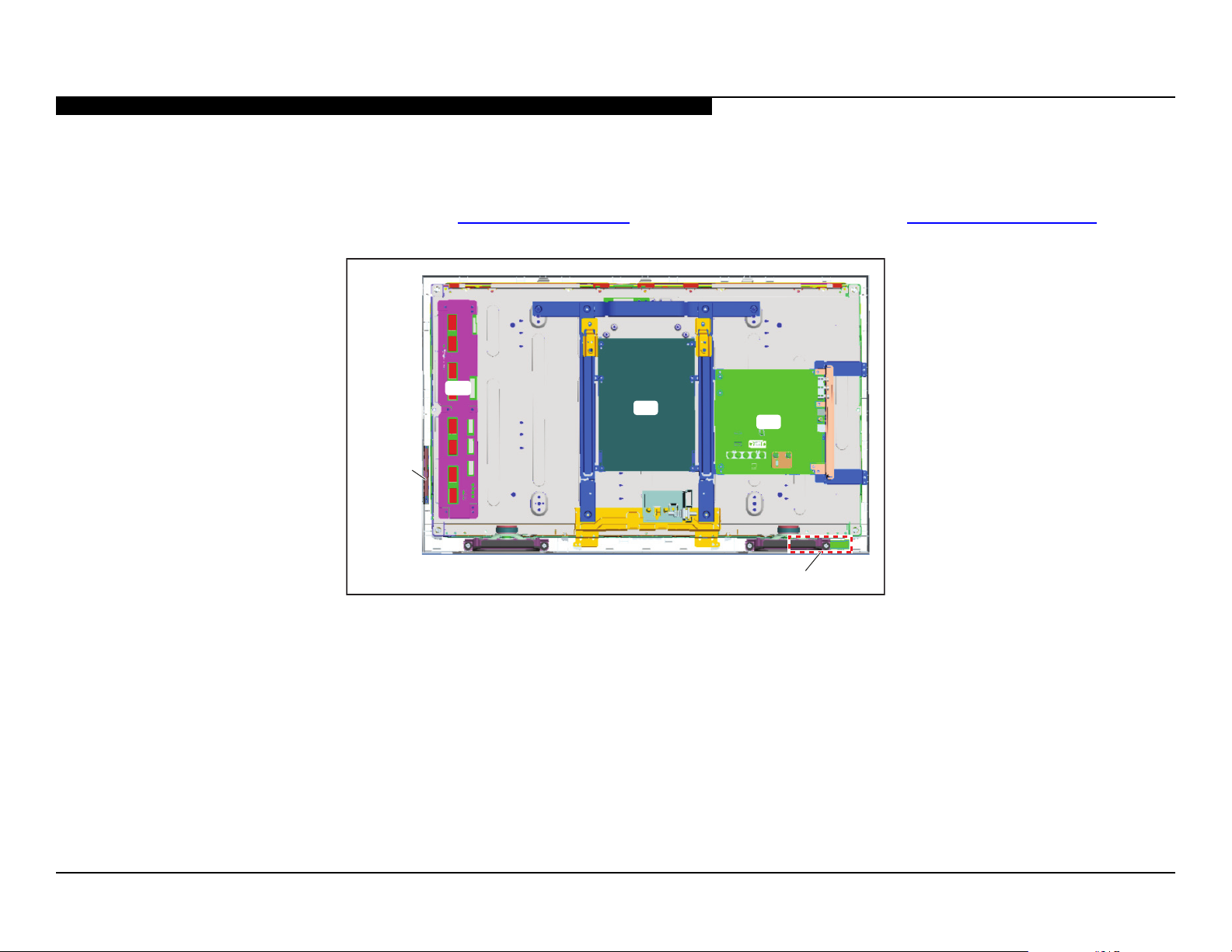
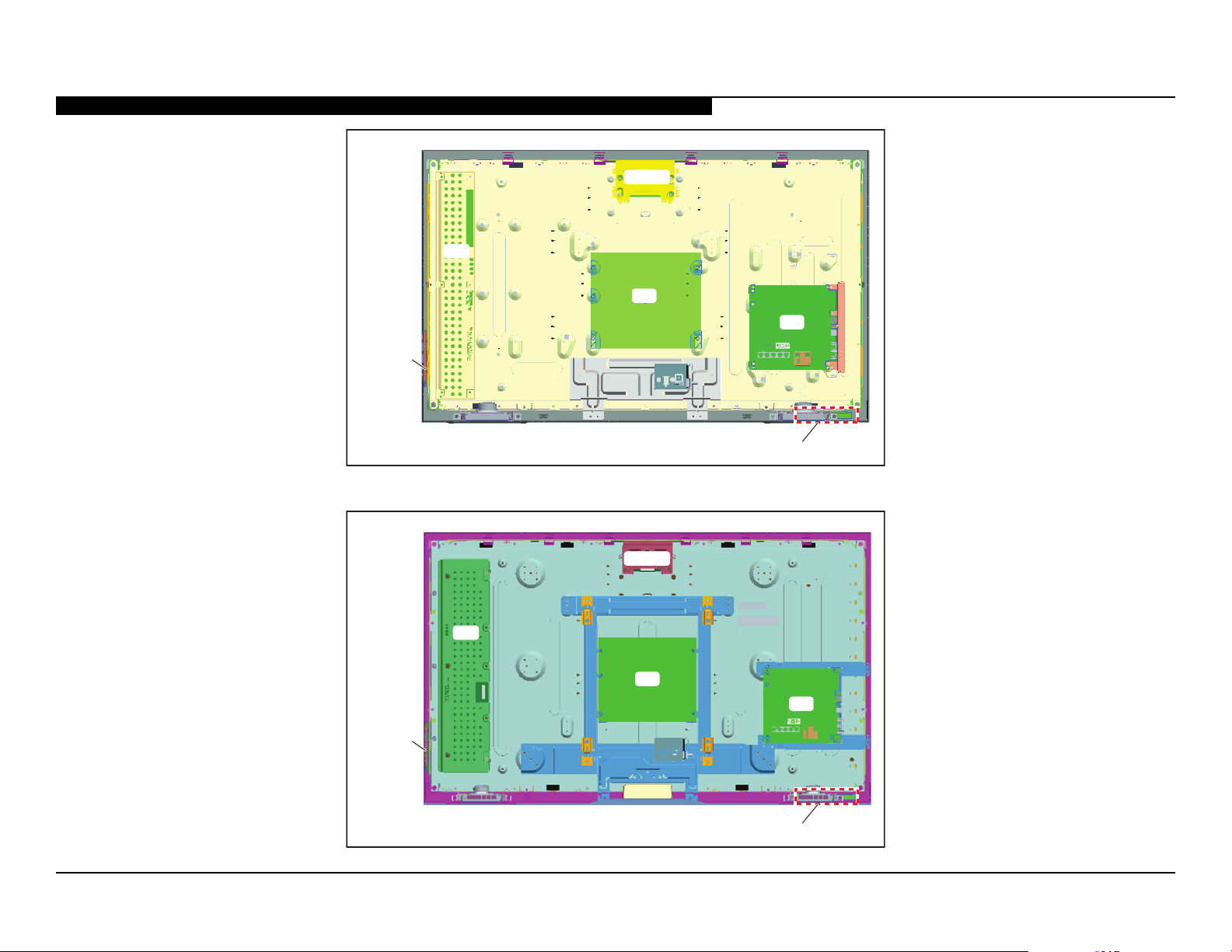
CHASSIS OVERVIEW
The primary circuits in the AZ3TK chassis consist of a Main Board (A Board), Power Supply Board (G Boards), the IR Board (H Board), the Switch Unit, and
the LCD Panel Assembly which includes the TCON Board and the Inverter MT Board.
NOTE: For connector part number information, refer to “Connectors” on page 19. For Wire Dressing information, refer to “Wire Dressing” on page 21.
INV
G
SWITCH
UNIT
A
H
BOARD LAYOUT FOR KDL-32BX355 ONLY
KDL-32BX355/40BX455/46BX455 3
Page 12
SWITCH
UNIT
SECTION 1 - FEATURES AND OVERVIEW
TCON
INV
G
A
H
BOARD LAYOUT FOR KDL-40BX455 ONLY
TCON
INV
G
A
SWITCH
UNIT
H
BOARD LAYOUT FOR KDL-46BX455 ONLY
KDL-32BX355/40BX455/46BX455 4
Page 13
SECTION 1 - FEATURES AND OVERVIEW
OVERALL CIRCUIT DESCRIPTION
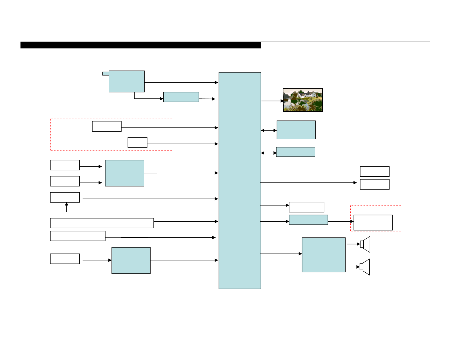
“Overall Block Diagram” on page 11 provides an overview of the AZ3TK
chassis. The following are descriptions of the boards and their functions.
MAIN BOARD
Common to all models utilizing the AZ3TK chassis, the Main Board contains
most of the video processing circuitry along with all audio processing.
Control of the television is accomplished via a CPU embedded within the
MT5366 processor. Below is a list of the key components located on the
Main Board.
TUNER
The tuner is a combination ATSC/NTSC unit. It can receive traditional
analog NTSC signals via cable or terrestrial along with ATSC digital signals
via terrestrial (8VSB) or cable (64 or 256 QAM).
MT5366 PROCESSOR
This IC performs the majority of the necessary audio and video processing
on the Main Board.
Analog Video Input Switch: All analog video sources are selected and
A/D converted and scaled (if necessary) to 1920 X 1080p 60HZ resolution.
Digital Audio and Video Decoder: The MPEG2 and Digital Dolby audio
streams are received from the tuner for decompression. All video sources
which are not native 1920 X 1080p 60HZ are scaled to this resolution.
Digital audio content is output to the class D amplier for processing and
amplication.
Audio Processing: Analog audio sources are selected and A/D converted
directly by the MT5389. The audio information is then processed digitally.
Digital audio from the tuner and HDMI sources is also input and processed.
Class D amplier provides the drive for the speakers.
HDMI Input and Switching: The customer can select the HDMI1 through
HDMI4 input. Each HDMI input contains a dedicated EDI NVM (not shown)
to provide display information data to any device connected via the HDMI
inputs.
CPU: The CPU internal to the MT5366 processor controls all aspects of
the television functions. Input from the user along with monitoring of critical
circuits is also performed by this CPU.
LVDS Transmitter: Integrated into the MT5366 is a Low Voltage Differential
Signaling (LVDS) transmitter. This circuit converts the 8-bit parallel RGB
video information into a set of high speed serial lines for noise-free
transmission to the TCON circuits located internally to the LCD panel.
POWER SUPPLY BOARD
The Power Supply Boards used in these models are the:
● G for all models
There are 2 distinct sections on the power supply:
Standby Supply: Continuously operational as long as AC power is applied,
the standby supply generates 3.3VDC for the circuits requiring power while
the unit is turned off. An unregulated 15-volt line is present to provide power
to the main relay, PFC and main power supply at turn-on.
Main Supply: Once the power supply receives a power-on command from
the CPU on the A board, the main switching supply is turned on to provide
a regulated 12V source, a dedicated un-regulated 15V for the audio circuits
and an unregulated 24V source for the inverter circuit.
IR BOARD
Designated as the H Board, the IR Board contains the power, standby, and
timer LED’s that is located on this board along with the IR remote receiver
and light level sensor.
SWITCH UNIT
This board contains the power, channel and volume up/down, and menu
buttons.
KDL-32BX355/40BX455/46BX455 5
Page 14
SECTION 1 - FEATURES AND OVERVIEW
LCD PANEL ASSEMBLY
The LCD Panel Assembly includes the LCD Panel, TCON Board, and LED
Backlight system.
The LCD Panel contains the actual liquid crystals, color lters, and
polarizers. The liquid crystals are manipulated by the applied voltage to
pass a specic amount of light - from the backlight - depending on the level
of voltage applied.
The TCON performs all the control, timing, charge, and discharge functions
driving the operation of the LCD Panel.
A new LCD Panel Assembly from parts will include the following items.
● LCD Panel
● TCON Board (Internal - not available as a replacement part.)
● Inverter MT Board
INVERTER MT BOARD
The inverter receives the unregulated 24V from the Power Supply Board
and generates the required high voltage AC to power the backlight lamps. A
control line to turn on the inverter (backlights on) is used in conjunction with
a dimmer control to vary the light level of the CCFL lamps.
KDL-32BX355/40BX455/46BX455 6
Page 15
SECTION 2 - TROUBLESHOOTING
Self Diagnosis
Supported model
OVERVIEW
This chapter provides information regarding the Self Diagnosis feature in
our TVs.
UPDATING THE SOFTWARE
The Self Diagnosis function is designed to provide information regarding
the problem with the TV, however, there are several issues that may be
resolved by updating the TV software to the latest version. Always check for
any issues that are software related. Most symptoms that are correctable
by software updates involve communications issues with other devices or
minor glitches in the operation of a specic function. Below is a list of some
of the symptoms that may be corrected with a software update:
● Fluctuations in picture brightness
● Intermittent picture freezing or noise
● Problems with certain inputs (especially HDMI)
● Intermittent or distorted audio
● Erratic remote control operation
● TV turns on and off by itself
● Loss of color
● Internet connectivity
● Certain features not working correctly
(photo or video le viewing)
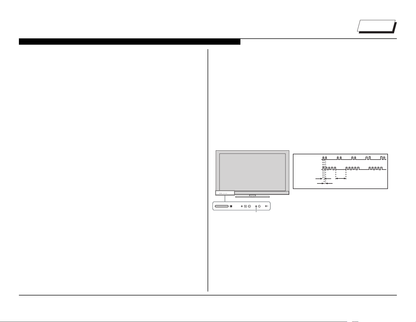
SELF DIAGNOSIS FUNCTION
Critical voltages and circuit operations are monitored by the CPU on the
Main Board. If an error is detected the Self Diagnosis function in the TV will
force the TV to shut down by the CPU. The monitored circuit in which the
fault occurred will automatically cause the CPU to blink the Standby LED
in groups of repeating sequences. The number of times the Standby LED
blinks indicates the possible cause of the problem.
Not all of the available protect codes are used in every model. For example,
models that don’t have the local dimming feature do not use the 4X blink
error as this circuit is found in models that are backlit with uorescent lamps.
The information in this section provides guidance in locating the possible
component causing the shutdown.
STANDBY LED BLINK COUNT
2 times
5 times
Standby LED
LED ON 0.3 sec.
LED OFF 0.3 sec.
LED DISPLAY & BLINK COUNT
LED OFF
3 sec.
KDL-32BX355/40BX455/46BX455 7
Page 16
SECTION 2 - TROUBLESHOOTING
K
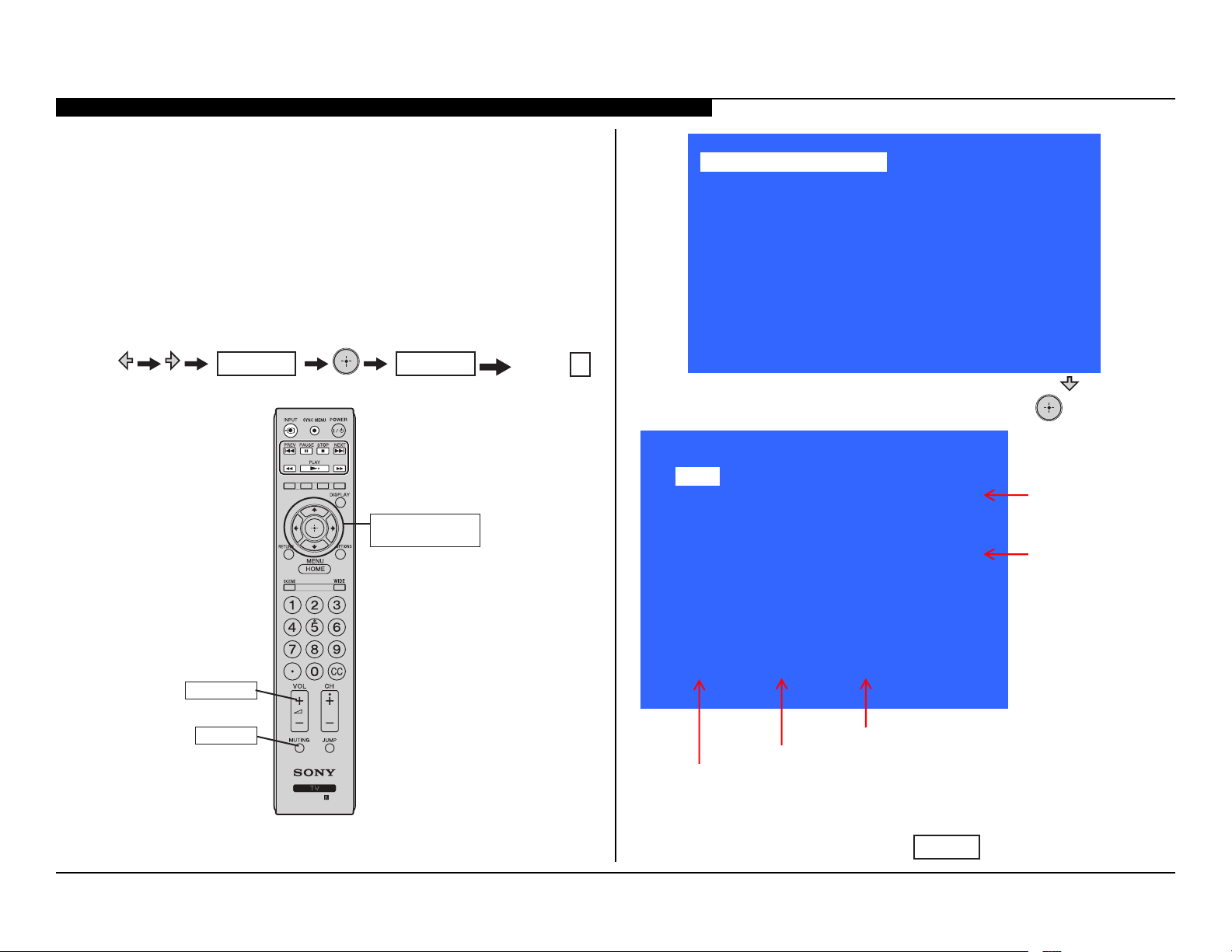
VIEWING THE SELF CHECK DIAGNOSIS HISTORY
When an error is detected, the Self Check screen records the error that
occurred. This is helpful in conrming past occurrences of an error, and for
determining if an error is intermittent when the customer is not sure what
is causing the television to shut down. If the screen displays a “0”, no error
has occurred.
You must got into Service Mode to access the Self Check menu.
1. TV must be in Standby mode. (Power On).
2. Press the following buttons on the Remote Commander within a
second of each other:
MUTING
MUTING
Onscreen cursor
and select button
Volume +
Service Mode
Sound Adjustment >>
Wide Band Tuning >>
Range Scan… >>
Self diagnosis history >>
Status Information… >>
LVDS Spectrum(%0) <[ 50 ]>
Panel Selection <[ T315XW04_V3 ]>
SERIAL NUMBER EDIT 1322132
MODEL NAME EDIT KDL-32BX355
[</>]Set [Menu] Exit
3. To access the Self diagnosis history page, press until Self
diagnosis history is highlighted, and then press .
SELF CHEC
Back <<
002 MAIN_ POWER 001
003 AUDIO_PROT 000
003 DC_ALERT1 000
004 BALANCER 000
005 TCON_ERR 000
005 PANEL_POWE 000
006 BACKLITE 000
007 TEMP_ERR 000
Indicates
an error
has
Indicates
no error
has
occurred
00150 00150 00007
VOLUME+
MUTING
Panel operation time by hour (MAX:65535)
Boot count (MAX:65535)
Total operation time by hour (MAX:65535)
4. Review the information to determine the most likely source of the
error.
[Menu] Exit
RM-YD081
5. To exit the Self Check, press
MENU
.
KDL-32BX355/40BX455/46BX455 8
Page 17
SECTION 2 - TROUBLESHOOTING
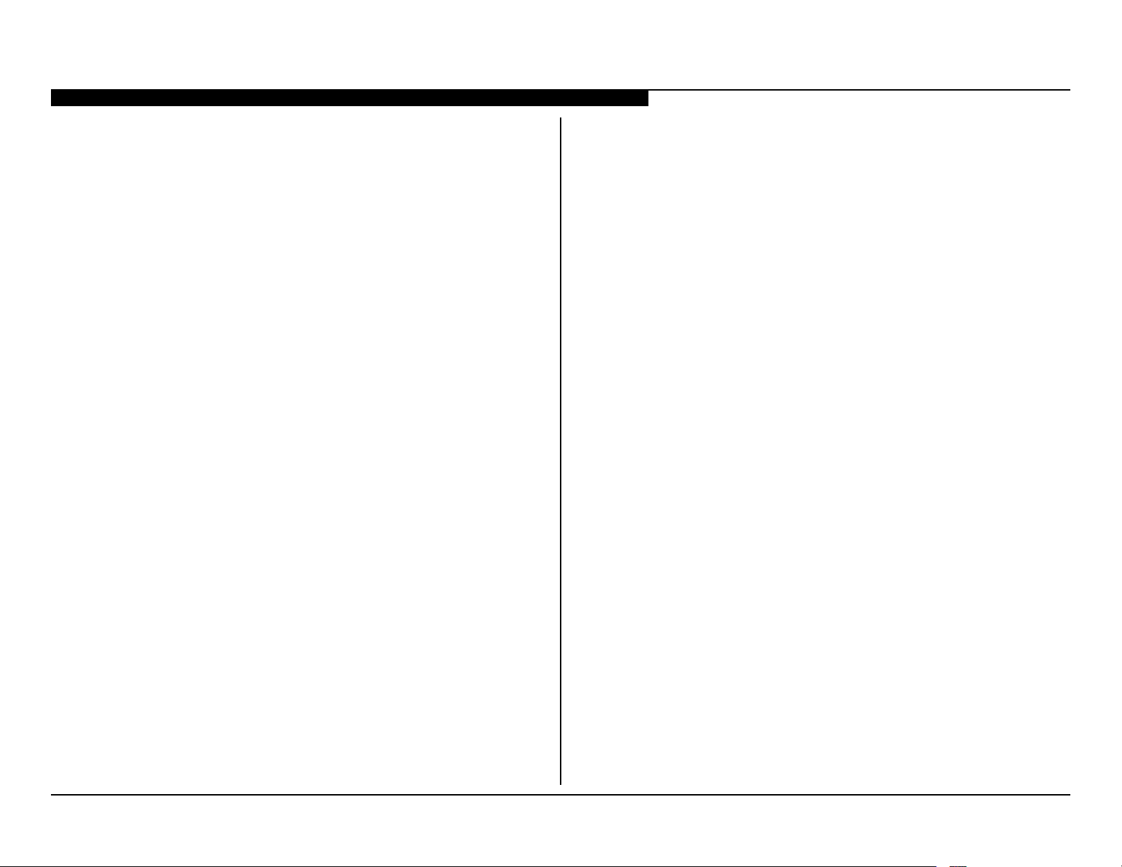
2X Blink - Main Power Error
A loss of REG12V from the power supply triggers this protect event. The
usual cause is a failure of the main switching supply. In some instances,
excessive loading on the secondary supply lines can cause the switching
regulator to stop, or fail again, if a replacement board is installed.
3X Blink- DC Regulator/Audio Error
The REG 5V and D3.3V source originating on the Main Board is monitored
for low-voltage conditions by the CPU. A failure causing a 3X shutdown
requires replacing the Main Board.
4X Blink – Balancer Error
NOT USED IN THIS MODEL SERIES
The 4X error code is only used on models incorporating local dimming LED
backlighting. If a failure occurs on the LD board or one of the LED’s fails in
the panel the TV will shut down and display this diagnostic code. Models
using conventional non-local dimming LED backlighting do not utilize this
error code.
5X Blink - TCON Error/Panel Error
The 5X blink protection mode indicates a communications error with the
timing control circuits (TCON Board) has occurred. If the TCON Board is
available for replacement, replace it, if not, replace the LCD Panel Assembly.
In rare cases a loose or defective LVDS cable could also be the cause.
7X Blink - Temperature Failure
A digital thermometer IC located on the Main Board provides a temperature
reading of the chassis and LCD panel. If the temperature exceeds a predetermined point the TV will shut down. If this problem occurs immediately
at turn-on, the temperature sensing IC has failed and replacing the main
board is required. If this occurs after the TV has been running for a while,
check for ventilation issues that could cause the TV to run hotter than
normal.
6X Blink - Backlight Converter System Failure
If the inverter circuits fails to generate high voltage or one or more of the
backlight lamps fails to light, the television will shut down and display this
diagnostics error. Observing for the presence of backlighting is crucial in
determining which component is likely at fault.
If the backlights turn on before the 6X shutdown occurs, it is safe to assume
that the inverter circuits are functioning and one of the lamps failed to ignite.
Replacing the LCD Panel assembly is necessary. If the backlights never
turn on before the 6X shutdown, the Inverter MT Board has failed. If this
board is available for replacement, replace it, if not, replace the LCD Panel
Assembly.
KDL-32BX355/40BX455/46BX455 9
Page 18
SECTION 2 - TROUBLESHOOTING
y
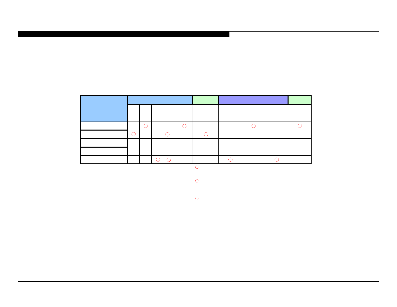
TRIAGE CHART
Use this general Triage Chart to determine what may possibly be causing the error before going out to the customers location.
5. Chart Color Code
1. Confirm the symptom from the customer.
2. Select that symptom from the chart.
3. Bring the primary component listed for that s
4. Follow the associated flowcharts in the Training Manual to isolate the board.
Board
2X 3X 5X 6X 7X
Main Board
Power Supply
H
Inverter
LCD Panel
*NOTE: REFER TO LCD PANEL SERVICE
MANUAL IN REFERENCE LIBRARY DATABASE
FOR CORRECT REPLACEMENT PARTS BASED
ON SERIAL NUMBER.
▲*
**
***
RED DOT: (Primary) Most likely defective part
BLUE Triangle: (Secondary) Possible defective part
Video Protection Modes
Whole
Screen
Distortion
Isolated
Area
Distortion
Power Audio
Dead set No Video
*
▲▲
* TV Immediate Shuts Off After Power ON &
7X
***Backlight Does NOT Turn ON before TV
Shuts Off ▲* Secondary Component
No Audio
**Backlight Turns ON before TV Shuts Off
KDL-32BX355/40BX455/46BX455 10
Page 19
SECTION 3 - FLOW CHARTS AND DIAGRAMS
BLOCK DIAGRAM
Tuner
Side I/O
HDMI1
HDMI2
VGA
UART
COMPONENT+COMPOSITE + AUDIO
VGA/HDMI AUDIO
CVBS
SIL9185ACTU
USB
IF 2
IF 1
CXD2828
DEMOD
.
MT5366
To Panel
DDR3 x 2
NAND Flash
SPDIF OUT
MAX9728
KEYPAD
IR/ LED
Side I/O
Head PHONE
/ AUDIO OUT
AMP
RJ45
RTL8201CP
STA339BWTR
ETHERNET
ETHERNET PHY
OVERALL BLOCK DIAGRAM
KDL-32BX355/40BX455/46BX455 11
Page 20
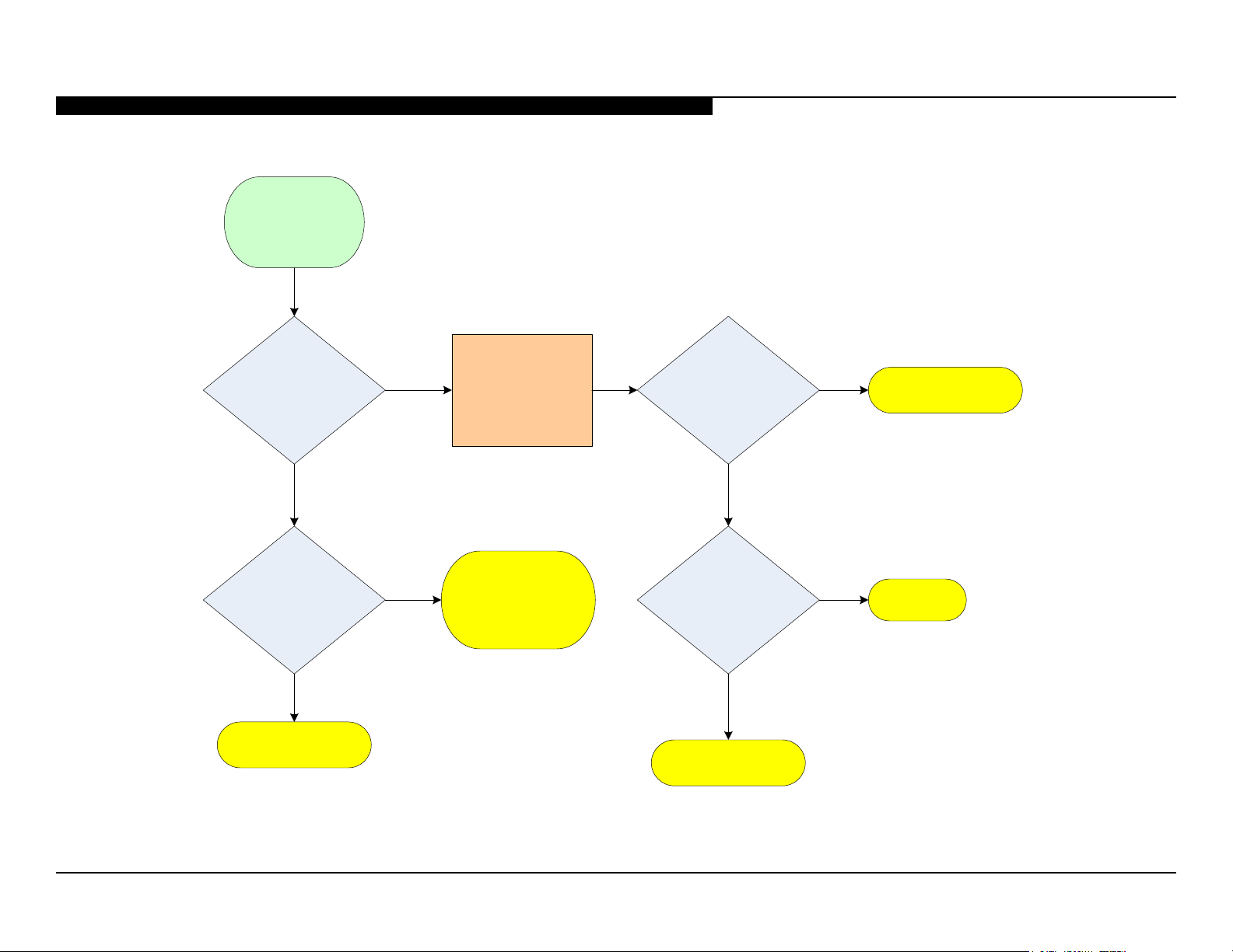
NO POWER
No Power
Does red standby
LED on front panel
light?
SECTION 3 - FLOW CHARTS AND DIAGRAMS
Press power
Yes
button while
monitoring pin 3 of
CN6401 on power
supply board
High (3.3V)
on pin 3?
Yes
Power Supply
Board*
No
Is standby LED
blinking?
No
Yes
See
Protection Shutdown
flowchart
High (3.3V)
No
on pin 2?
No
Yes
Main Board*
Power Supply
Board*
Power Supply
Board*
NO POWER FLOWCHART
KDL-32BX355/40BX455/46BX455 12
Page 21
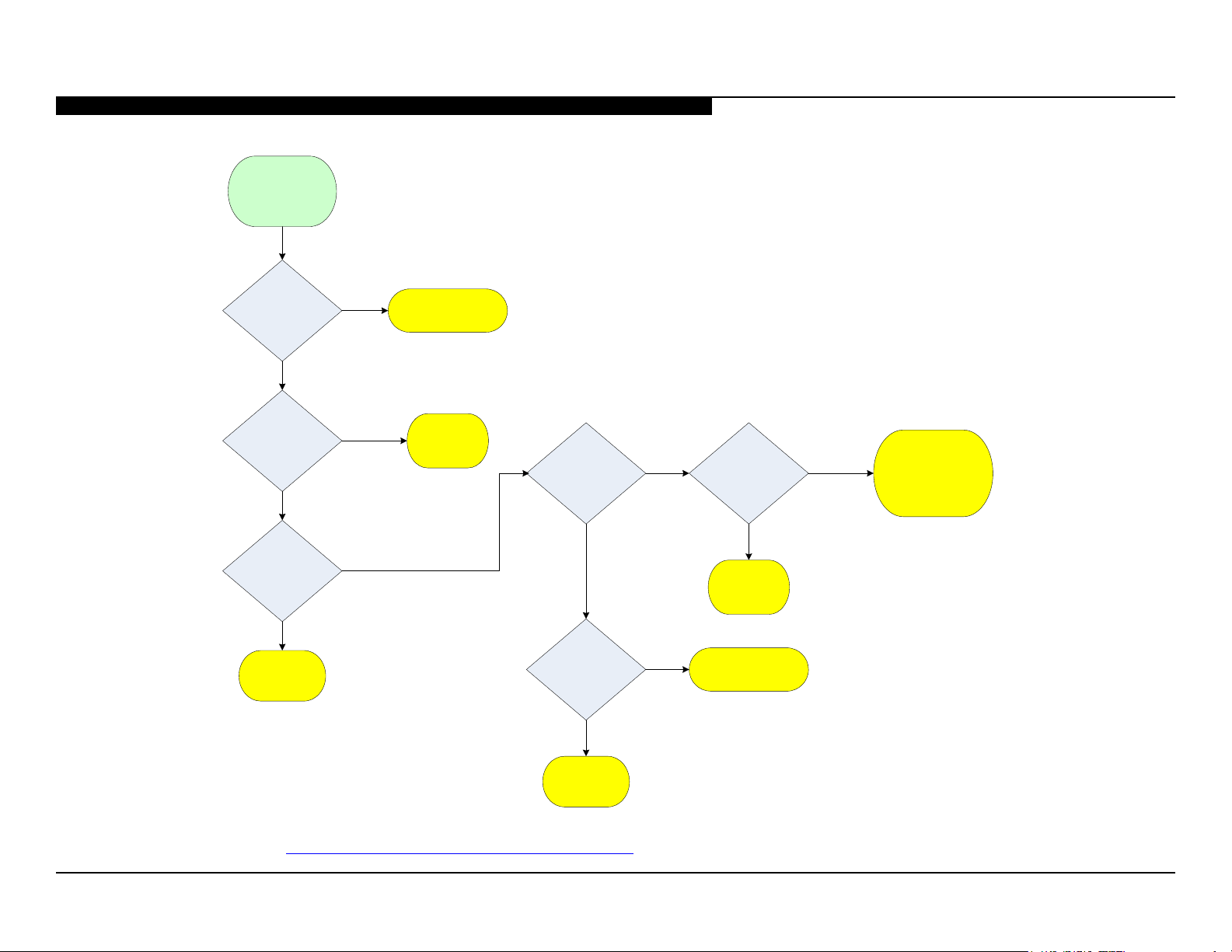
STANDBY LED BLINKING
Protect
Shutdown.
Standby LED
Blinking
SECTION 3 - FLOW CHARTS AND DIAGRAMS
2X
No
3X
No
5X
Yes
LCD Panel*
Yes
Yes
No
Power Supply
Board*
Main Board*
6X
Yes
“SONY” logo
appears before
shutdown?
Yes
No
No
7X
Immediately
Main Board*
Power Supply
Board*
After a While
Check room
temperature and
ventilation around
unit
LCD Panel*
PROTECTION SHUTDOWN FLOWCHART
*For Part Number information, Refer to “Section 4 - Disassembly/Part Number Information” on page 16.
KDL-32BX355/40BX455/46BX455 13
Page 22
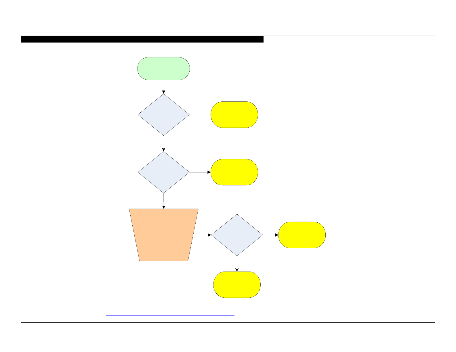
NO VIDEO
SECTION 3 - FLOW CHARTS AND DIAGRAMS
No Video
Backlights
turned on?
Yes
Any OSD
graphics
present?
No
Unplug LVDS
connector at
TCON while unit
is running. This
may need to be
done more than
once
No
Yes
Inverter Board
or LCD Panel*
Main Board*
Any flashes
seen on
screen?
Yes
No
LCD Panel*
Main Board*
NO VIDEO FLOWCHART
*For Part Number information, Refer to “Section 4 - Disassembly/Part Number Information” on page 16.
KDL-32BX355/40BX455/46BX455 14
Page 23
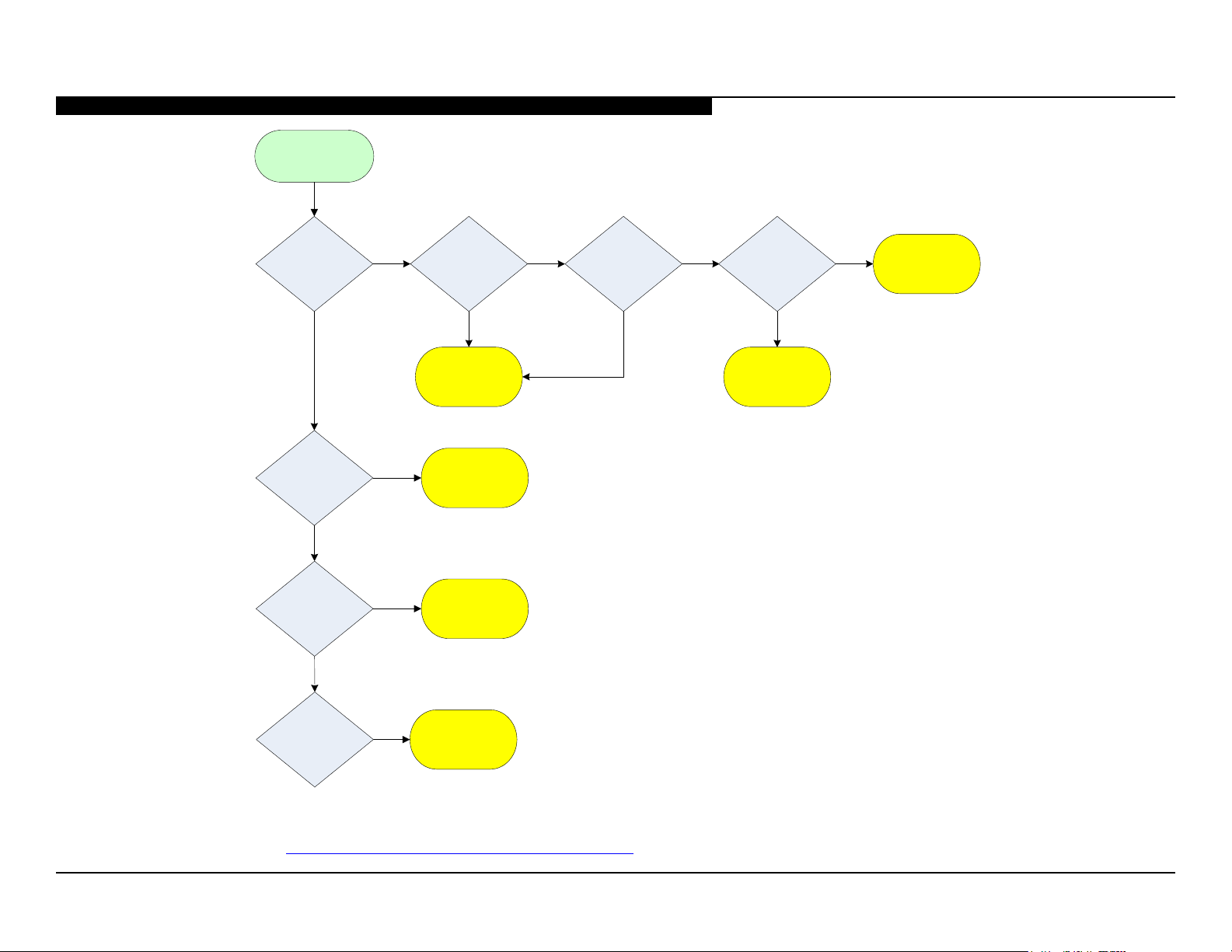
Video Distortion
SECTION 3 - FLOW CHARTS AND DIAGRAMS
Is distortion
across entire
screen?
No
Any horizontal
lines?
No
Any single or
isolated vertical
lines?
No
Yes
Yes
Yes
Improper of
missing colors?
Yes
Main Board*
LCD Panel*
LCD Panel*
No
Vertical lines
or bars?
No
Yes
Lines move
when wide-mode
changed?
No
LCD Panel*
Yes
Main Board*
More than 1
vertical band?
*For Part Number information, Refer to “Section 4 - Disassembly/Part Number Information” on page 16.
Yes
LCD Panel*
VIDEO DISTORTION FLOWCHART
KDL-32BX355/40BX455/46BX455 15
Page 24
SECTION 4 - DISASSEMBLY/PART NUMBER INFORMATION
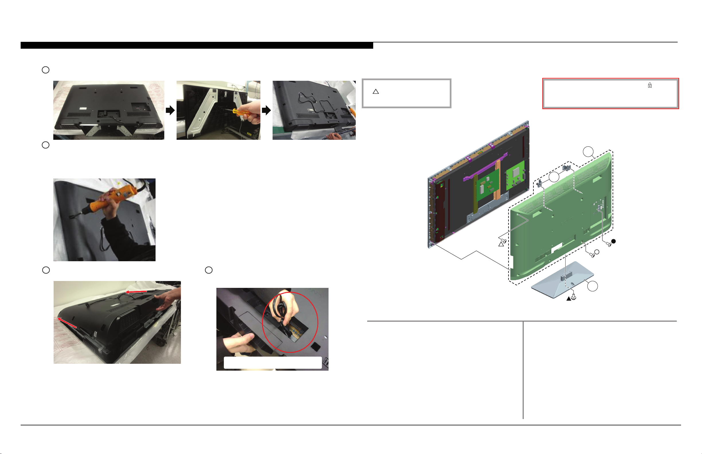
TABLE-TOP STAND AND REAR COVER REMOVAL
A
Gently place LCD TV face down onto a soft cloth and remove 3 screws from Table-Top Stand.
B
Remove screws from Rear Cover.
15 from KDL-32BX355 Only
17 from KDL-40BX455 Only
19 from KDL-46BX455 Only
CAUTION: Do not damage the Power Board Connector and AC Power Cord when removing the Rear Cover.
Components not identied by a part number or
description are not stocked because they are seldom
required for routine service.
NOTE: The components identied by shading
and ! mark are critical for safety. Replace only
with part number specied.
The component parts of an assembly are indicated by the
reference numbers in the far right column of the parts list
and within the dotted lines of the diagram.
NOTE: The components identied by a red outline and a mark contain
condential information. Specic instructions must be adhered to whenever
these components are repaired and/or replaced.
See Appendix A: Encryption Key Components in the back of this manual.
2
Items marked with an asterisk are not stocked since
*
they are seldom required for routine service. Expect
some delay when ordering these components.
1
C
Carefully lift Rear Cover from bottom side and push
forward to release top hooks.
D
Hold Power Supply Cord while lifting up Rear
Cover, then pass Power Supply Cord through Rear
Cover opening.
Do not pull the AC Power Cord or damage
the connector on the Power Board.
3
REF. NO. PART NO. DESCRIPTION [ASSEMBLY INCLUDES] REF. NO. PART NO. DESCRIPTION [ASSEMBLY INCLUDES]
1 4-423-357-01 REAR COVER (32APOT) [2]
(KDL-32BX355 ONLY)
1 4-423-358-01 REAR COVER (40APOT) [2]
(KDL-40BX455 ONLY)
1 4-423-359-01 REAR COVER (46APOT) [2]
(KDL-46BX455 ONLY)
2 4-410-252-01 BRACKET, VESA (APOT)
3 X-2584-208-1 STAND ASSEMBLY (32APOT)
(KDL-32BX355 ONLY)
3 X-2584-209-1 STAND ASSEMBLY (40APOT)
(KDL-40BX455 ONLY)
3 X-2584-210-1 STAND ASSEMBLY (46APOT)
(KDL-46BX455 ONLY)
▲ 2-580-608-01 SCREW, +PSW M5X16
(SCREWS TO ATTACH TABLE-TOP STAND TO LCD TV)
For product protection and safety reasons, Sony strongly recommends
that you use the screws provided with the TV.
CAUTION: These screws cannot be used to secure the TV to the Wall
Mount Brackets
△ 2-580-640-01 SCREW, +BVTP2 4X16
● 2-580-592-01 SCREW, +PSW M3X8
○ 4-159-298-01 SCREW, +PSW M4X10
KDL-32BX355/40BX455/46BX455 16
Page 25
SECTION 4 - DISASSEMBLY/PART NUMBER INFORMATION
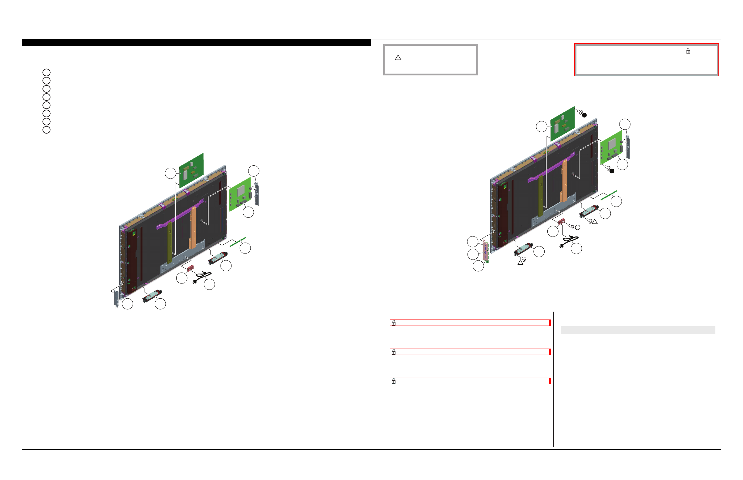
MAIN BOARD (A) AND POWER SUPPLY BOARD (G) REMOVAL
A
Disconnect Power Supply Cord from G Board.
B
Release clips and lift-up AC Cover.
C
Remove screws and disconnect connectors from G Board.
D
Release clips and slide-out Side Cover.
E
Remove screws and disconnect connectors from A Board.
F
Remove screws and disconnect connectors from Left and Right Speakers.
G
Release clips and disconnect connector from H Board.
H
Disconnect connector, then tilt Switch Unit left and lift-up.
C
D
E
NOTE: The components identied by shading
and ! mark are critical for safety. Replace only
with part number specied.
61
NOTE: The components identied by a red outline and a mark contain
condential information. Specic instructions must be adhered to whenever
these components are repaired and/or replaced.
See Appendix A: Encryption Key Components in the back of this manual.
51
52
53
54
56
60
G
59
F
B
A
H
F
REF. NO. PART NO. DESCRIPTION [ASSEMBLY INCLUDES] REF. NO. PART NO. DESCRIPTION [ASSEMBLY INCLUDES]
51 4-410-249-01 COVER, SIDE IO (APOT)
52 1-895-178-11 A BOARD, COMPLETE
(KDL-32BX355 ONLY)
AFTER REPLACING THE MAIN BOARD, YOU MUST UPDATE THE
SOFTWARE TO THE LATEST VERSION
52 1-895-178-21 A BOARD, COMPLETE
(KDL-40BX455 ONLY)
AFTER REPLACING THE MAIN BOARD, YOU MUST UPDATE THE
SOFTWARE TO THE LATEST VERSION
52 1-895-178-31 A BOARD, COMPLETE
(KDL-46BX455 ONLY)
AFTER REPLACING THE MAIN BOARD, YOU MUST UPDATE THE
SOFTWARE TO THE LATEST VERSION
58
57
55
53 1-895-179-11 H BOARD, MOUNTED
54 1-858-772-21 SPEAKER 4X10 (TOR)
! 55 1-839-929-11 POWER-SUPPLY CORD
56 4-410-250-01 COVER, AC (APOT)
57 1-858-772-11 SPEAKER 4X10 (TOL)
58 1-490-189-11 SWITCH UNIT
59 4-264-270-01 KEY PAD (GT)
60 4-410-247-01 COVER, KEY (APOT)
61 1-895-180-11 G BOARD, COMPLETE
(KDL-32BX355 ONLY)
61 1-895-181-11 G BOARD, COMPLETE
(KDL-40BX455/46BX455 ONLY)
△ 2-580-640-01 SCREW, +BVTP2 4X16
○ 4-159-298-01 SCREW, +PSW M4X10
●
2-580-592-01 SCREW, +PSW M3X8
KDL-32BX355/40BX455/46BX455 17
Page 26
SECTION 4 - DISASSEMBLY/PART NUMBER INFORMATION
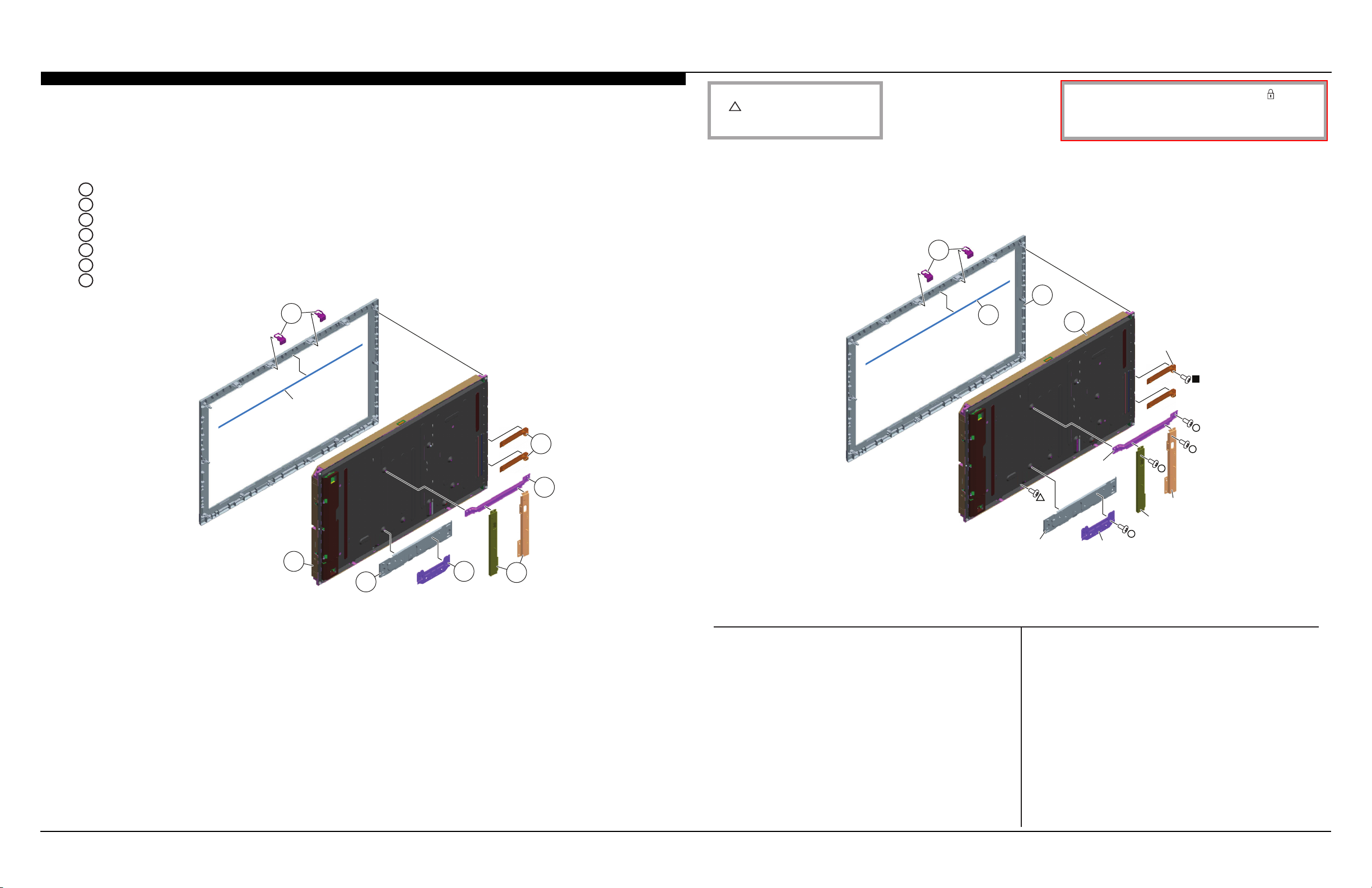
LCD PANEL REMOVAL
CAUTION: The LCD Panel is attached to the Bezel using double-sided tape. (KDL-32BX355 only)
NOTE: The Panel Frames are not included with the LCD Panel and must be reattached to the replacement panel for the
KDL-32BX355/46BX455 models only.
A
Remove Panel Brackets from Bezel.
B
Remove screws from Main Board Brackets.
C
Remove screws from Upper Frame.
D
Remove screws from Left and Right Frames.
E
Remove screws from Bottom Frame.
F
Remove screws from Lower Frame.
G
Remove screws from LCD Panel to detach from Bezel, then carefully lift up LCD Panel.
A
Double Sided
Tape
NOTE: The components identied by shading
and ! mark are critical for safety. Replace only
with part number specied.
101
102
NOTE: The components identied by a red outline and a mark contain
condential information. Specic instructions must be adhered to whenever
these components are repaired and/or replaced.
See Appendix A: Encryption Key Components in the back of this manual.
103
104
MB Frames
B
C
G
F
E
D
CLEANING THE LCD PANEL
CAUTION: When cleaning the TV, be sure to unplug the power cord to avoid any chance of electric shock.
Clean the cabinet of the TV with a dry soft cloth, and wipe the LCD screen gently with a soft cloth.
; Stubborn stains may be removed with a cloth slightly moistened with a solution of mild soap and warm water.
; If using a chemically pretreated cloth, please follow the instruction provided on the package.
; Never use strong solvents such as a thinner, alcohol or benzine for cleaning.
; Periodic vacuuming of the ventilation openings is recommended to ensure proper ventilation.
; Do Not use paper towels, any type of abrasive pad, rags, rubber or vinyl materials to clean the screen. Using these
materials could easily scratch the screen which may result in permanent damage.
; Do Not use any cleaning product containing alkaline/acid cleaner, scouring powder, or volatile solvent, such as alcohol,
ammonia, benzine, thinner or insecticide. Using any of these harsh cleaners may result in permanent damage to the
screen.
; Do Not spray water or detergent directly onto the TV screen . If liquid drips into the bottom of the screen it may cause a
failure.
Upr
Frame
Rt Frame
Lt Frame
Lwr Frame
REF. NO. PART NO. DESCRIPTION [ASSEMBLY INCLUDES] REF. NO. PART NO. DESCRIPTION [ASSEMBLY INCLUDES]
101 4-410-251-01 SUPPORT, PNL (APOT)
102 4-428-102-01 MASK TAPE, DOUBLE ADHESIVE
(KDL-32BX355 ONLY)
103 4-423-354-01 BEZEL (32APOT)
(KDL-32BX355 ONLY)
103 4-423-355-01 BEZEL (40APOT)
(KDL-40BX455 ONLY)
103 4-423-356-01 BEZEL (46APOT)
(KDL-46BX455 ONLY)
104 NA LCD PANEL
FOR ALL LCD PANEL AND TCON BOARD PART NUMBER
INFORMATION REFER TO THE LCD PANELS SERVICE MANUAL
△ 2-580-640-01 SCREW, +BVTP2 4X16
■ 7-685-646-79 SCREW, +BVTP 3X8
Btm Frame
○
4-159-298-01 SCREW, +PSW M4X10
KDL-32BX355/40BX455/46BX455 18
Page 27
SECTION 4 - DISASSEMBLY/PART NUMBER INFORMATION
2
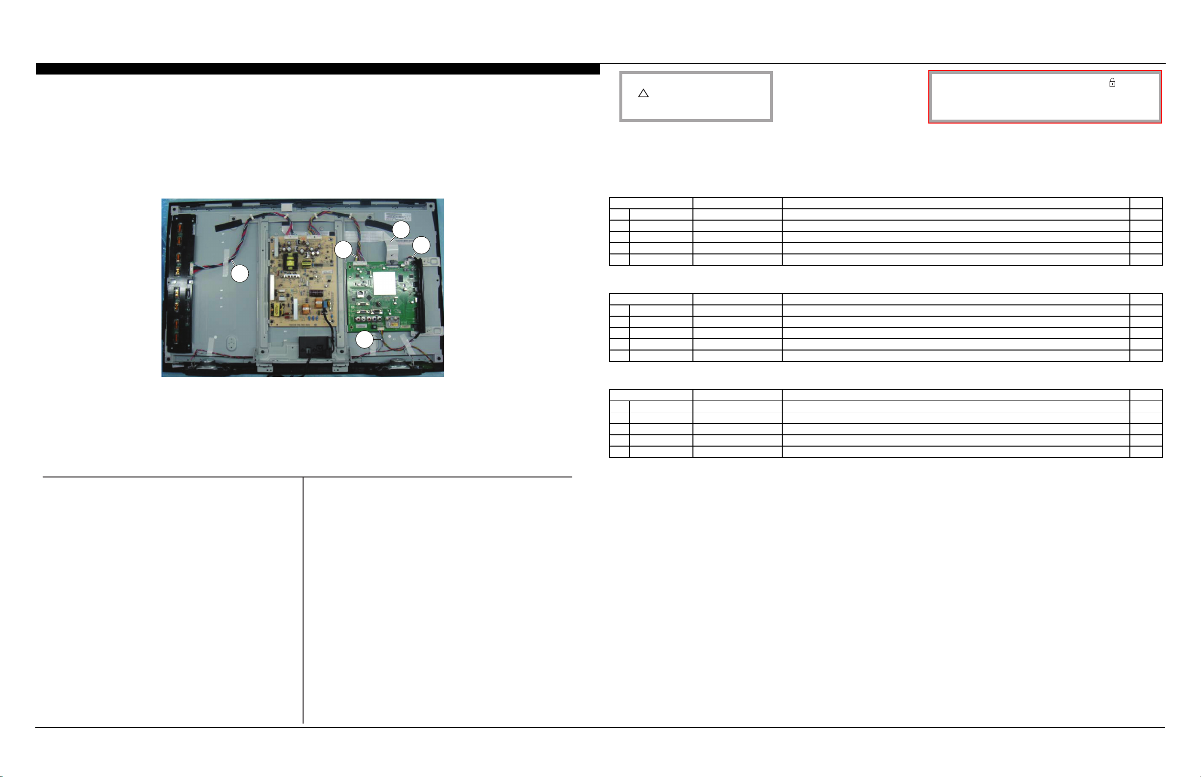
CONNECTORS
155
153
154
152
151
NOTE: The components identied by shading
and ! mark are critical for safety. Replace only
with part number specied.
SCREWS
KDL-32BX355
P/N DESCRIPTION REMARKS TOTAL
2-580-608-01 SCREW, +PSW M5X16 TABLE-TOP STAND(3) 3
▲
2-580-640-01 SCREW, +BVTP2 4X16 RC(9), SPKR-L(2), SPKR-R(2), PNL to BEZ(2) 13
△
2-580-592-01 SCREW, +PSW M3X8 RC TERMINAL AREA(1), A BOARD(4), G BOARD(6) 11
●
4-159-298-01 SCREW, +PSW M4X10 RC(5), AC CVR(1), UPR FRM(2), LT FRM(2), RT FRM(2), BTM FRM(2) 14
○
7-685-646-79 SCREW, +BVTP 3X8 VESA BRKTS(4), MB BRKTS(2) 6
■
KDL-40BX455
P/N DESCRIPTION REMARKS TOTAL
2-580-608-01 SCREW, +PSW M5X16 TABLE-TOP STAND(3) 3
▲
2-580-640-01 SCREW, +BVTP2 4X16 RC(11), SPKR-L(2), SPKR-R(2), PNL to BEZ(2) 15
△
2-580-592-01 SCREW, +PSW M3X8 RC TERMINAL AREA(1), A BOARD(4), G BOARD(6) 11
●
4-159-298-01 SCREW, +PSW M4X10 RC(5), AC CVR(1), BTM FRM(3) 9
○
7-685-646-79 SCREW, +BVTP 3X8 VESA BRKTS(4), STND BRKTS(6) 10
■
NOTE: The components identied by a red outline and a mark contain
condential information. Specic instructions must be adhered to whenever
these components are repaired and/or replaced.
See Appendix A: Encryption Key Components in the back of this manual.
REF. NO. PART NO. DESCRIPTION [ASSEMBLY INCLUDES] REF. NO. PART NO. DESCRIPTION [ASSEMBLY INCLUDES]
151 1-910-106-04 CONNECTOR ASSEMBLY 32 4P MB-SP
(KDL-32BX355 ONLY)
151 1-910-106-08 CONNECTOR ASSEMBLY 40 4P MB-SP
(KDL-40BX455 ONLY)
151 1-910-106-12 CONNECTOR ASSEMBLY 46 4P MB-SP
(KDL-46BX455 ONLY)
152 1-910-105-34 (LVDS) CONNECTOR ASSEMBLY 32
(KDL-32BX355 ONLY)
152 1-910-105-33 (LVDS) CONNECTOR ASSEMBLY 40
(KDL-40BX455 ONLY)
152 1-910-105-32 (LVDS) CONNECTOR ASSEMBLY 46
(KDL-46BX455 ONLY)
154 1-910-106-05 CONNECTOR ASSEMBLY 32 12P MB-H&KEY
(KDL-32BX355 ONLY)
154 1-910-106-09 CONNECTOR ASSEMBLY 40 12P MB-H&KEY
(KDL-40BX455 ONLY)
154 1-910-106-13 CONNECTOR ASSEMBLY 46 12P MB-H&KEY
(KDL-46BX455 ONLY)
155 1-910-106-07 CONNECTOR ASSEMBLY 32 14P PSU-INV
(KDL-32BX355 ONLY)
155 1-910-106-11 CONNECTOR ASSEMBLY 40 14P PSU-INV
(KDL-40BX455 ONLY)
155 1-910-106-15 CONNECTOR ASSEMBLY 46 14P PSU-INV
(KDL-46BX455 ONLY)
153 1-910-106-06 CONNECTOR ASSEMBLY 32 14P MB-PSU
(KDL-32BX355 ONLY)
153 1-910-106-10 CONNECTOR ASSEMBLY 40 14P MB-PSU
(KDL-40BX455 ONLY)
153 1-910-106-14 CONNECTOR ASSEMBLY 46 14P MB-PSU
(KDL-46BX455 ONLY)
KDL-46BX455
P/N DESCRIPTION REMARKS TOTAL
2-580-608-01 SCREW, +PSW M5X16 TABLE-TOP STAND(3) 3
▲
2-580-640-01 SCREW, +BVTP2 4X16 RC(13), SPKR-L(2), SPKR-R(2), PNL to BEZ(2), 13
△
2-580-592-01 SCREW, +PSW M3X8 RC TERMINAL AREA(1), A BOARD(4), G BOARD(5) 10
●
4-159-298-01 SCREW, +PSW M4X10 RC(5), AC CVR(1), UPR FRM(2), LT FRM(1), RT FRM(1), LWR FRM(2), BTM FRM(3), MB FRMS(
○
7-685-646-79 SCREW, +BVTP 3X8 VESA BRKTS(4), MB FRMS(2), STND BRKT(6) 12
■
17
KDL-32BX355/40BX455/46BX455 19
Page 28
SECTION 4 - DISASSEMBLY/PART NUMBER INFORMATION
ACCESSORIES AND PACKAGING
PART NO. DESCRIPTION
X-2584-211-1 BAG ASSEMBLY, SCREW
1-756-988-21 BATTERY, MANGANESE (R6)
4-415-639-42 GUIDE, QUICK SET UP
4-415-637-42 MANUAL, INSTRUCTION
4-416-690-42 SUPPLEMENT(STAND INSTALLATION)
REMOTE COMMANDER
PART NO. DESCRIPTION
1-489-991-11 REMOTE COMMANDER (RM-YD081)
KDL-32BX355/40BX455/46BX455 20
Page 29
SECTION 4 - DISASSEMBLY/PART NUMBER INFORMATION
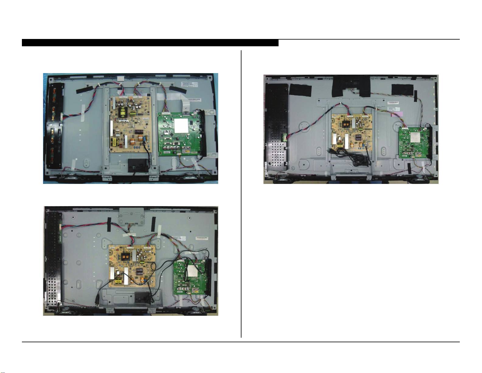
WIRE DRESSING
WIRE DRESSING FOR KDL-32BX355 ONLY
WIRE DRESSING FOR KDL-40BX455 ONLY
WIRE DRESSING FOR KDL-46BX455 ONLY
KDL-32BX355/40BX455/46BX455 21
Page 30
SECTION 5 - UPDATES AND ADJUSTMENTS
OVERVIEW
The models in this manual utilize a “generic” type of Main Board, therefore a
software update must be performed and certain service adjustment settings
must be changed or conrmed whenever the Main Board, LCD Panel, or
TCON Board is replaced.
There are 2 reasons for updating the software on the TVs.
● Software updates for customers
These updates are for enhancements or improvements that have
been made to the software after the TV was released.
● Software update for servicers
These updates are specically for servicers to use during a service
call.
SOFTWARE UPDATES FOR CUSTOMERS
The subject of software updates is very important. The televisions of today
have advanced to the point where they are not simply a television anymore.
They are evolving into devices that are designed to integrate with numerous
other devices found in the home. Some examples are: portable audio and
video devices, still cameras, home computer networks and accessing the
internet to name a few.
Communications with these varying devices requires that the television be
compatible with varying communications protocols. Although standards
are detailed for each of these protocols, the real world dictates that
occasional errors may occur that could prevent devices from operating or
communicating properly.
Keeping the software in the television up-to-date is a procedure that is
normally handled by the owner of the television. Most customers who own
computers and other digital devices are familiar with and are accustomed
to updating the software in their products. If a customer contacts the Sony
Customer Support Center and it is deemed to be correctable with a software
update, the issue is handled at the customer level.
Software updates can be performed by:
● Customer Manual Downloads: Software updates can be performed
by the customer by placing it on a USB device to be loaded onto
the TV. The instructions for downloading the software le vary
from chassis to chassis and sometimes from model to model.
The customer is provided with the instructions to properly format
the USB device, unzip the le, and the procedures for loading the
software into the television.
● Network Downloads: Internet software updates are becoming
more prevalent as more and more models incorporate home
network capabilities. This method is the most practical since the
television will check for the latest version of software. The models
with this type of chassis provide the customer with a choice of
turning the automatic software update feature on or off. If set to on,
the television will lookup software information while the unit is in
standby. If a newer version is available, it will be downloaded and
installed without any input from the customer.
● Built-in Tuner: OTA or cable sources having the proper station that
is transmitting software update data packets. Although the ability
to transmit software update is possible in this way, it is the least
common and is reserved for particular situations where a critical
update is “forced”, thereby updating the TV without any input from
the customer.
SOFTWARE UPDATES FOR SERVICERS
Replacement Main Boards are now stocked with basic software. Once the
replacement board is installed in the TV, the most current software needs to
be installed using a USB device containing the necessary software.
This new method of supplying Main Boards signicantly reduces the
complexity of replacing the Main Boards. Information about the LCD panel
is stored on the TCON circuits. This information is automatically loaded
onto the Main Board when the TV is powered up. With the correct software
version the Main Board and/or the TCON can be replaced more efciently.
KDL-32BX355/40BX455/46BX455 22
Page 31
SECTION 5 - UPDATES AND ADJUSTMENTS
SOFTWARE UPDATE RESPONSIBILITY
Software updates are designed to be performed by the customer. Warranty
repairs in which the issue can be resolved by a software update are not
reimbursable. Most issues involving software updates are handled by the
customer service center and should not be directed to an authorized service
center. It is the responsibility of the servicer to prevent service calls for
issues that involve software updates. Exceptions to this are certain cases
whereby the customer is unable or unwilling to perform the task. In this
situation, the servicer will be notied and receive the proper authorization
for reimbursement.
It is the servicer’s responsibility, however, to make certain that any TV
requiring a legitimate service is running the latest software version
and to install it if necessary.
CHECKING THE SOFTWARE VERSION
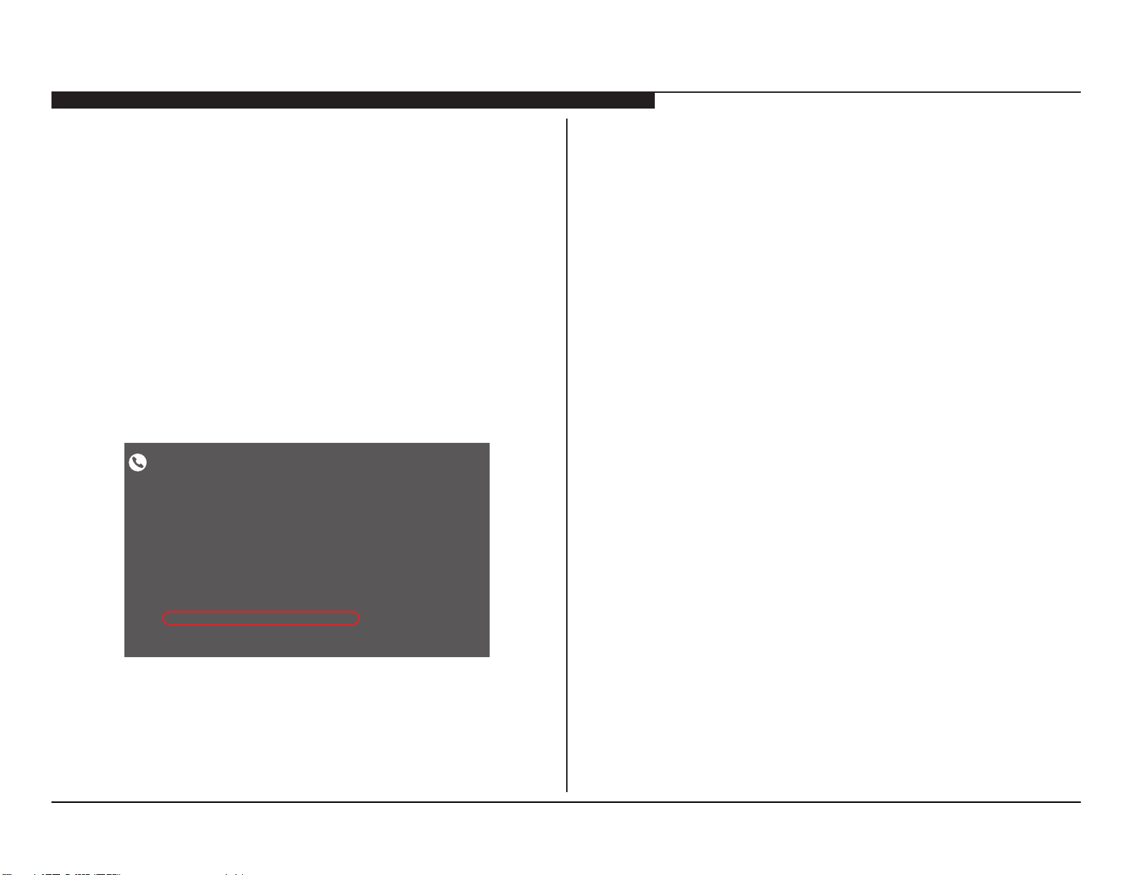
The easiest way to check the version of software that is currently on the TV
is to access the Contact Sony screen by using the customer menu.
Póngase en contacto con Sony
Póngase en contacto directament con Sony si tiene algún problems con el TV:
Sitio Web de soporte técnico:
Teléfono de contacto en Brasil
Región capital y metropolitana:
Otras regiones:
Sitio Web de soporte técnico: www.sony.AR/CONTACTANOS
Teléfono de contacto en Argentina: 011-6770-7669
Tengo la siguiente información a mano:
Nombre del modelo: KDL-40BX455
Número de serie:
Versión del software:
Please refer to the rear of this TV.
SONY_Tarte_SA_1.06
www.sony.co,.br/contato
4003 SONY (7669.)
0800 880 SONY (7669).
EXAMPLES OF SOFTWARE CORRECTABLE SYMPTOMS
Always check for any known and/or listed issues that are software
related. Most symptoms that are correctable by software updates involve
communications issues with other devices or minor glitches in the operation
of a specic function. Below is a list of some of the symptoms that may be
corrected with a software update:
● Fluctuations in picture brightness
● Intermittent picture freezing or noise
● Problems with certain inputs (especially HDMI)
● Intermittent or distorted audio
● Erratic remote control operation
● Unit turns on and off by itself
● Loss of color
● Internet connectivity
● Certain features not working correctly
(photo or video le viewing)
EXAMPLE OF SOFTWARE VERSION
LOCATED ON THE CONTACT SONY SCREEN
KDL-32BX355/40BX455/46BX455 23
Page 32
SECTION 5 - UPDATES AND ADJUSTMENTS
ACCESSING SERVICE ADJUSTMENT MODE
Use the following information after replacing the Main Board or the LCD
Panel to ensure all features of the TV are available.
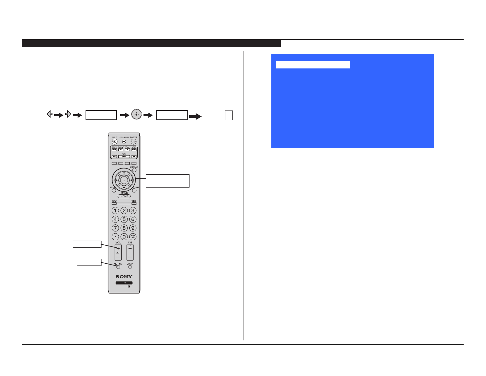
1. TV must be in Standby mode. (Power On).
2. Press the following buttons on the Remote Commander within a
second of each other:
MUTING
MUTING
Onscreen cursor
and select button
Volume +
Service Mode
Sound Adjustment >>
Wide Band Tuning >>
Range Scan… >>
Self diagnosis history >>
Status Information… >>
LVDS Spectrum(%0) <[ 50 ]>
Panel Selection <[ T315XW04_V3 ]>
SERIAL NUMBER EDIT 1322132
MODEL NAME EDIT KDL-32BX355
[</>]Set [Menu] Exit
SAMPLE SERVICE MODE MENU
COMPLETING SERVICE REQUIREMENTS WHEN REPLACING THE MAIN BOARD
The following must be performed after replacing the Main Board to ensure
that all of the features for the TV will be available.
; Viewing the Status Information
; Adding the Serial Number
; Selecting the Model Name
VOLUME+
MUTING
RM-YD081
KDL-32BX355/40BX455/46BX455 24
Page 33
SECTION 5 - UPDATES AND ADJUSTMENTS
VIEWING THE STATUS INFORMATION
After replacing the Main Board, LCD Panel, or TCON Board, you MUST
UPDATE the SOFTWARE to the latest version. Verify the latest software is
installed before proceeding to the service adjustments.
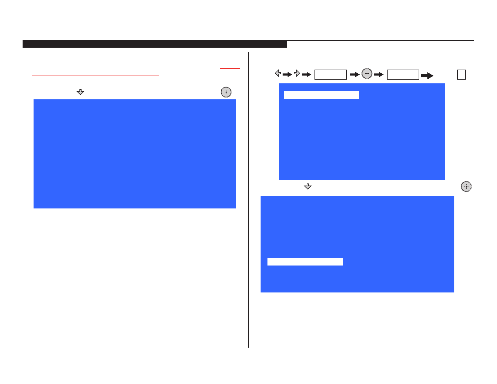
3. Press until Status Information is selected, then press .
Main Micro
SW Version SONY_2012_TOSCA_1.04
NVM Version: 1
Boot Version: 0.01
Panel Version: V0.004
PQ Version: V1.00b
AQ Version: AQ1.001
4. Verify the latest software version is installed.
5. Do one of the following:
a. If the latest software is installed, proceed to Adding the Serial
Number.
b. If the latest software is not installed, update the software and
then proceed to Adding the Serial Number.
2. Press the following buttons on the Remote Commander within a
second of each other:
Sound Adjustment >>
Wide Band Tuning >>
Range Scan… >>
Self diagnosis history >>
Status Information… >>
LVDS Spectrum(%0) <[ 50 ]>
Panel Selection <[ T315XW04_V3 ]>
SERIAL NUMBER EDIT 1322132
MODEL NAME EDIT KDL-32BX355
3. Press until Serial Number Edit is selected, and then press .
Sound Adjustment >>
Wide Band Tuning >>
Range Scan… >>
Self diagnosis history >>
Status Information… >>
LVDS Spectrum(%0) <[ 50 ]>
Panel Selection <[ T315XW04_V3 ]>
SERIAL NUMBER EDIT <[
MODEL NAME EDIT <[ KDL-32BX355 ]>
MUTING
Service Mode
Service Mode
MUTING
[</>]Set [Menu] Exit
1 3 2 2 1 3 2
Volume +
]>
ADDING THE SERIAL NUMBER
Verify before proceeding to the next step:
; Veried Status Information
1. TV must be in Standby mode. (Power On).
[</>]Set [Menu] Exit
KDL-32BX355/40BX455/46BX455 25
Page 34
SECTION 5 - UPDATES AND ADJUSTMENTS
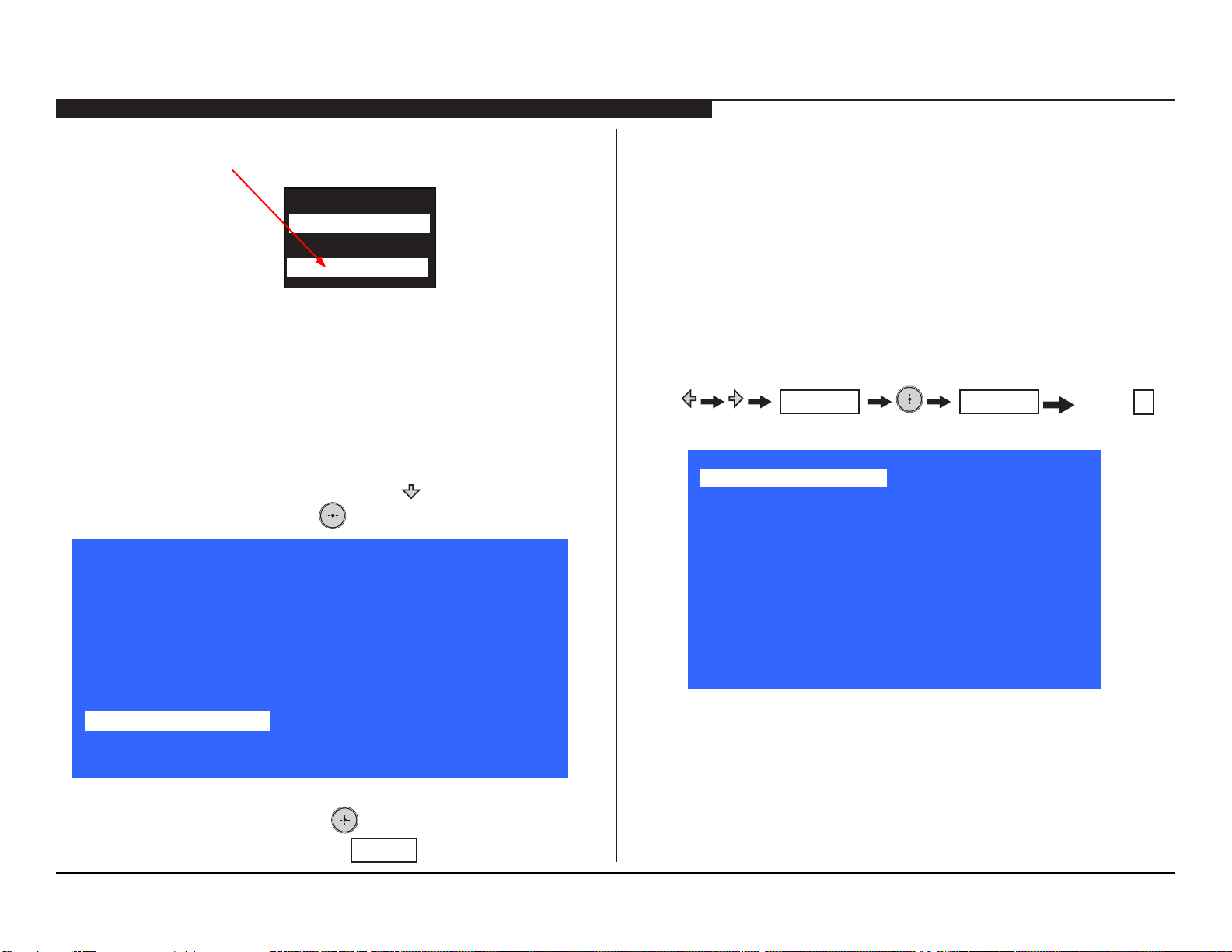
4. Locate the serial number for the TV on the side of the Rear Cover
of the TV.
MODEL NO
KDL-32BX455
SERIAL NO
1322132
5. Using the Remote Commander, enter the correct serial number.
6. Proceed to Selecting the Model Name.
SELECTING THE MODEL NAME
Verify before proceeding to the next step:
; Veried Status Information
; Added the Serial Number
7. From the Service Mode menu, press until Model Name Edit is
selected, and then press
Service Mode
Sound Adjustment >>
Wide Band Tuning >>
Range Scan… >>
Self diagnosis history >>
Status Information… >>
LVDS Spectrum(%0) <[ 50 ]>
Panel Selection <[ T315XW04_V3 ]>
SERIAL NUMBER EDIT <[ 1322132 ]>
MODEL NAME EDIT <[
.
K D L - 3 2 B X 3 5 5
]>
COMPLETING SERVICE REQUIREMENTS WHEN REPLACING THE LCD PANEL
The following must be performed after replacing the LCD Panel.
NOTE: The TCON Board is internal and cannot be replaced.
; Viewing the Status Information
; Changing the LVDS Spectrum
; Selecting the LCD Panel
1. TV must be in Standby mode. (Power On).
2. Press the following buttons on the Remote Commander within a
second of each other:
Sound Adjustment >>
Wide Band Tuning >>
Range Scan… >>
Self diagnosis history >>
Status Information… >>
LVDS Spectrum(%0) <[ 50 ]>
Panel Selection <[ T315XW04_V3 ]>
SERIAL NUMBER EDIT 1322132
MODEL NAME EDIT KDL-32BX355
MUTING
Service Mode
MUTING
[</>]Set [Menu] Exit
Volume +
[</>]Set [Menu] Exit
8. Using the Remote Commander, enter the correct Model Name.
9. To save the change, press .
10. To exit the Self Check, press
MENU
.
KDL-32BX355/40BX455/46BX455 26
Page 35
SECTION 5 - UPDATES AND ADJUSTMENTS
VIEWING THE STATUS INFORMATION
After replacing the Main Board, LCD Panel, or TCON Board, you MUST
UPDATE the SOFTWARE to the latest version. Verify the latest software is
installed before proceeding to the service adjustments.
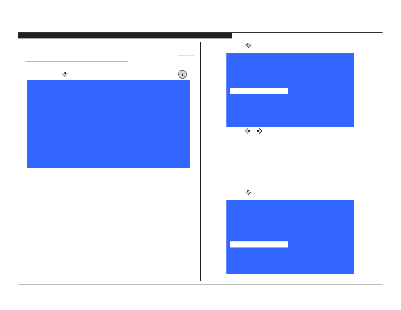
3. Press until Status Information is selected, then press .
Main Micro
SW Version SONY_2012_TOSCA_1.04
NVM Version: 1
Boot Version: 0.01
Panel Version: V0.004
PQ Version: V1.00b
AQ Version: AQ1.001
4. Verify the latest software version is installed.
5. Do one of the following:
a. If the latest software is installed, proceed to Changing the
LVDS Spectrum.
b. If the latest software is not installed, update the software and
then proceed to Changing the LVDS Spectrum.
CHANGING THE LVDS SPECTRUM
Verify before proceeding to the next step:
; Veried Status Information
6. Press until LVDS Spectrum (%) is selected.
Service Mode
Sound Adjustment >>
Wide Band Tuning >>
Range Scan… >>
Self diagnosis history >>
Status Information… >>
LVDS Spectrum(%0) <[ 50 ]>
Panel Selection <[ T315XW04_V3 ]>
SERIAL NUMBER EDIT 1322132
MODEL NAME EDIT KDL-32BX355
[</>]Set [Menu] Exit
7. Press or to change the data value.
8. Proceed to Selecting the LCD Panel
SELECTING THE LCD PANEL
Verify before proceeding to the next step:
; Veried Status Information
; Changed the LVDS Spectrum
9. Press until Panel Selection is selected.
Service Mode
Sound Adjustment >>
Wide Band Tuning >>
Range Scan… >>
Self diagnosis history >>
Status Information… >>
LVDS Spectrum(%0) <[ 50 ]>
Panel Selection <[ T315XW04_V3 ]>
SERIAL NUMBER EDIT 1322132
MODEL NAME EDIT KDL-32BX355
[</>]Set [Menu] Exit
KDL-32BX355/40BX455/46BX455 27
Page 36
SECTION 5 - UPDATES AND ADJUSTMENTS
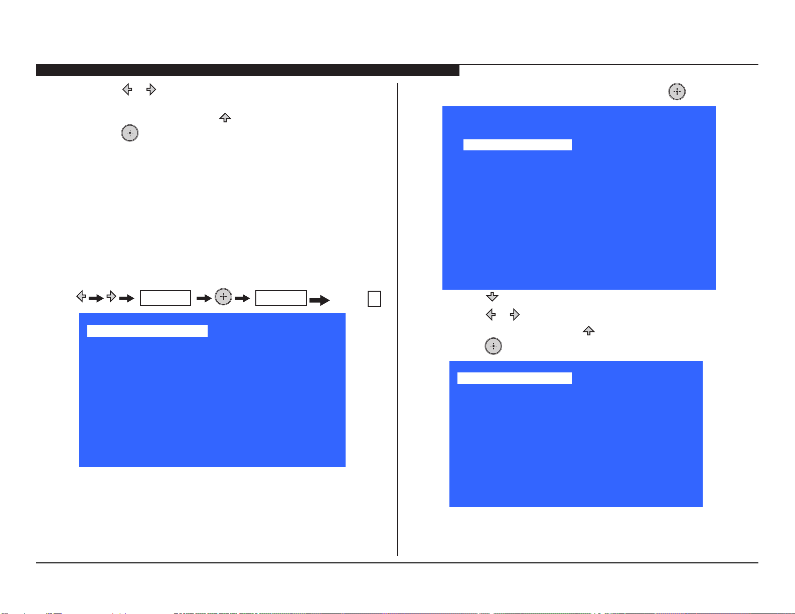
10. Press or to select the correct panel for the model being
repaired.
11. To save the changes, press until the Back is selected, then
press .
OPTIONAL SERVICE ADJUSTMENTS
The following are optional adjustments.
ADJUSTING THE SOUND
The following information is to adjust the sound.
1. TV must be in Standby mode. (Power On).
2. Press the following buttons on the Remote Commander within a
second of each other:
Sound Adjustment >>
Wide Band Tuning >>
Range Scan… >>
Self diagnosis history >>
Status Information… >>
LVDS Spectrum(%0) <[ 50 ]>
Panel Selection <[ T315XW04_V3 ]>
SERIAL NUMBER EDIT 1322132
MODEL NAME EDIT KDL-32BX355
MUTING
Service Mode
MUTING
[</>]Set [Menu] Exit
Volume +
3. To access the Sound Adjustment page, press .If the
Service Mode
Sound Adjust
Back <<
Sound Mode <[ Standard ]>
EQ [120Hz] <[ 1.1dB ]>
EQ [2000Hz] <[ 1.0dB ]>
EQ [500Hz] <[ 0.9dB ]>
EQ [1.2KHz] <[ 0.8dB ]>
EQ [3KHz] <[ 0.9dB ]>
EQ [7.5KHz] <[ 1.0dB ]>
EQ [12KHz] <[ 1.1dB ]>
Bass Offset <[ ]>
Treble Offset <[ ]>
[</>]Set [Menu] Exit
4. Press until the Sound Mode you want to change is selected.
5. Press or to change the data value.
6. To save the changes, press until the Back is selected, then
press .
Service Mode
Sound Adjustment >>
Wide Band Tuning >>
Range Scan… >>
Self diagnosis history >>
Status Information… >>
LVDS Spectrum(%0) <[ 50 ]>
Panel Selection <[ T315XW04_V3 ]>
SERIAL NUMBER EDIT 1322132
MODEL NAME EDIT KDL-32BX355
[</>]Set [Menu] Exit
7. Proceed to Wide Band Tuning Adjustments.
KDL-32BX355/40BX455/46BX455 28
Page 37
SECTION 5 - UPDATES AND ADJUSTMENTS
WIDE BAND TUNING ADJUSTMENTS
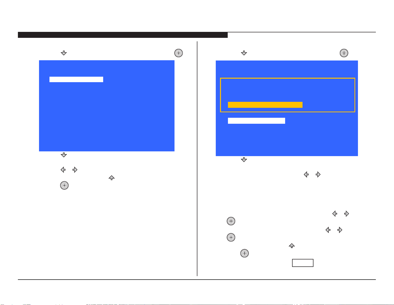
1. Press until Wide Band Tuning is selected, then press .
Service Mode
Wide Band Tuning
Back <<
Wide Band 1 <[ Blank ]>
Wide Band 2 <[ Blank ]>
Wide Band 3 <[ Blank ]>
Wide Band 4 <[ Blank ]>
Wide Band 5 <[ Blank ]>
Wide Band 6 <[ Blank ]>
Wide Band 7 <[ Blank ]>
Wide Band 8 <[ Blank ]>
Wide Band 9 <[ Blank ]>
Wide Band 10 <[ Blank ]>
[</>]Set [Menu] Exit
2. Press until the Wide Band option you want to change is
selected.
3. Press or to change the data value.
4. To save the changes, press until the Back is selected, then
press .
5. Proceed to Range Scan Adjustments
RANGE SCAN ADJUSTMENTS
1. Press until Range Scan is selected, then press .
Service Mode
Range Scan
Scan with a range of channels. Cable
0%
Back <<
Range Mode <[ Analog/Digital ]>
From Channel <[ 1 ]>
To Channel <[ 135 ]>
[</>]Set [Menu] Exit
2. Press until the Wide Band option you want to change is
selected.
3. To change the Range Mode press or to change the data
value to one of the following:
; Analog
; Digital
; Analog/Digital
4. To start the scan of the From Channels, press or then press
.
5. To start the scan of the To Channels, press or then press
.
6. To save the changes, press until the Back is selected, then
press .
7. To exit the Self Check, press
MENU
.
KDL-32BX355/40BX455/46BX455 29
Page 38
is a trademark of Sony Electronics
Reproduction in whole or part without written permission is prohibited. All rights reserved
English
© 2012.3
9-883-879-01
Sony Corporation
Sony Technology Center
Technical Services
Service Publication Department
2012CJ74WEB-1
Printed in USA
KDL-32BX355/40BX455/46BX455 30
Page 39
APPENDIX A: ENCRYPTION KEY COMPONENTS
Encryption key components developed by Sony Corporation contain condential information, and shall be handled under the non-disclosure obligations
provided in the applicable agreement with Sony Corporation (and/or its subsidiary).
As part of this agreement specic instructions must be adhered to whenever a Circuit Board containing encryption key components is repaired and/or replaced
pursuant to the following:
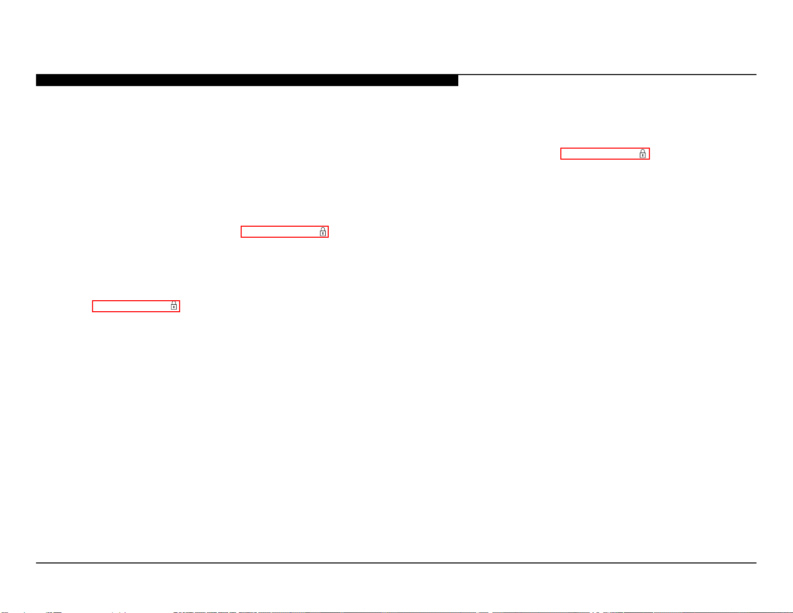
1. In the service manual the Circuit Board(s) containing encryption key components shall be identied with a red outline and a .
2. Only repair boards or components listed in the service manual shall be utilized for replacement and/or repair.
3. Disassembly, decryption, or reverse-engineering component(s) is strictly prohibited.
4. Any board in which the Servicer replaces an encryption key component must be placed back into the set it orignally came from and the replaced
defective component MUST BE DESTROYED. Boards cannot be swapped.
5. If a Circuit Board identied with a red outline and a in the service manual is deemed to be defective:
a. and if a core charge is imposed and is covered under the product warranty, the defective un-repaired or modied board MUST BE RETURNED
to Sony.
b. and if the core charge is NOT covered under the product warranty, the defective un-repaired or modied board MUST BE DESTROYED.
6. If a unit is destroyed (such as eld scrap), the Circuit Board identied with a
red outline and a in the service manual MUST BE DESTROYED.
KDL-32BX355/40BX455/46BX455 A-1
 Loading...