

Sony KDL-26P2520, KDL-32P2520, KDL-26P2530, KDL-32P2530, KDL-40P2530 Schematic

HISTORY
Model Name :
SERVICE MANUAL
Click on Page Number to display detail of changes.
Date Part Number Description of Revisions
Original Manual
KDL-26/32P2520, KDL-26/32/40P2530
Version
1.09-927-542-01 2007.01

SE-1
RM-ED007
SERVICE MANUAL
MODEL
KDL-26P2520
KDL-32P2520
KDL-26P2530
KDL-32P2530
KDL-40P2530
COMMANDER DEST
RM-ED007 AEP
RM-ED007 AEP
RM-ED007 AEP
RM-ED007 AEP
RM-ED007 AEP
SE-1
MODEL
KDL-26P2520
KDL-32P2520
KDL-26P2530
KDL-32P2530
KDL-40P2530
COMMANDER DEST
CHASSIS
RM-ED007 UK
RM-ED007 UK
RM-ED007 UK
RM-ED007 UK
RM-ED007 UK
KDL-26P2520 / KDL-32P2520
KDL-26P2530 / KDL-32P2530 / KDL-40P2530
FLAT PANEL COLOR TV
- 1 -
RM-ED007

SE-1
RM-ED007
TABLE OF CONTENTS
Section Title Pag e Section Title Pa ge
Caution ................................................................ 3
Specifications ...................................................... 4
Connectors .......................................................... 6
Self Diagnosis ..................................................... 7
1. GENERAL ................................................................... 8
2. DISASSEMBLY
2-1. Stand Removal .................................................... 16
2-2. Rear Cover Removal ........................................... 16
2-3. Speaker Removal ................................................ 17
2-4. A1/A1P Board Removal ..................................... 17
2-5. BDTR-2 Board Removal .................................... 18
2-6. G1 or G2 Board Removal................................... 18
2-7. H1/H1P Board Removal ..................................... 19
2-8. H2/H2P Board Removal ..................................... 19
2-9. H3/H3P Board Removal ..................................... 20
2-10. LCD Panel Removal ........................................... 20
3. CIRCUIT ADJUSTMENTS
3-1. Electrical Adjustments ....................................... 21
3-2. Test Mode 2 ....................................................... 23
3-3. TT OSD Labels .................................................. 24
4. DIAGRAMS
4-1. Block Diagrams(1) ............................................. 25
Block Diagrams(2) ............................................. 26
Block Diagrams(3) ............................................. 27
Block Diagrams(4) ............................................. 28
Block Diagrams(5) ............................................. 29
4-2. Circuit Board Location ........................................ 29
4-3. Schematic Diagrams and Printed Wiring
Boards ................................................................. 29
A1/A1P Board Schematic Diagram .................... 30
A1/A1P Printed Wiring Board ........................... 33
BDTR-2 Board Schematic Diagram ................... 34
BDTR-2 Printed Wiring Board ........................... 44
G1 Board Schematic Diagram
(KDL-26/32P2520/30) ....................................... 46
G1 Printed Wiring Board
(KDL-26/32P2520/30) ....................................... 48
G2 Board Schematic Diagram
(KDL-40P2530) ................................................. 50
G2 Printed Wiring Board (KDL-40P2530) ........ 52
H1/H1P Board Schematic Diagram .................... 54
H1/H1P Printed Wiring Board ........................... 55
H2/H2P Board Schematic Diagram .................... 54
H2/H2P Printed Wiring Board ........................... 55
H3/H3P Board Schematic Diagram .................... 54
H3/H3P Printed Wiring Board ........................... 55
4-4. Semiconductors .................................................. 56
WARNING !!
AN ISOLATION TRANSFORMER SHOULD BE USED DURING
ANY SERVICE WORK TO AVOID POSSIBLE SHOCK HAZARD
DUE TO LIVE CHASSIS, THE CHASSIS OF THIS RECEIVER IS
DIRECTLY CONNECTED TO THE POWER LINE.
5. EXPLODED VIEWS
5-1. Chassis................................................................ 58
5-2. Stand, Rear Cover, Power Leads........................ 60
6. ELECTRICAL PARTS LIST .................................. 61
SAFETY-RELATED COMPONENT WARNING !!
COMPONENTS IDENTIFIED BY SHADING AND MARKED
THE SCHEMATIC DIAGRAMS, EXPLODED VIEWS AND IN THE
PARTS LIST ARE CRITICAL FOR SAFE OPERATION. REPLACE
THESE COMPONENTS WITH SONY PARTS WHOSE PART
NUMBERS APPEAR AS SHOWN IN THIS MANUAL OR IN
SUPPLEMENTS PUBLISHED BY SONY.
ON
- 2 -
CAUTION
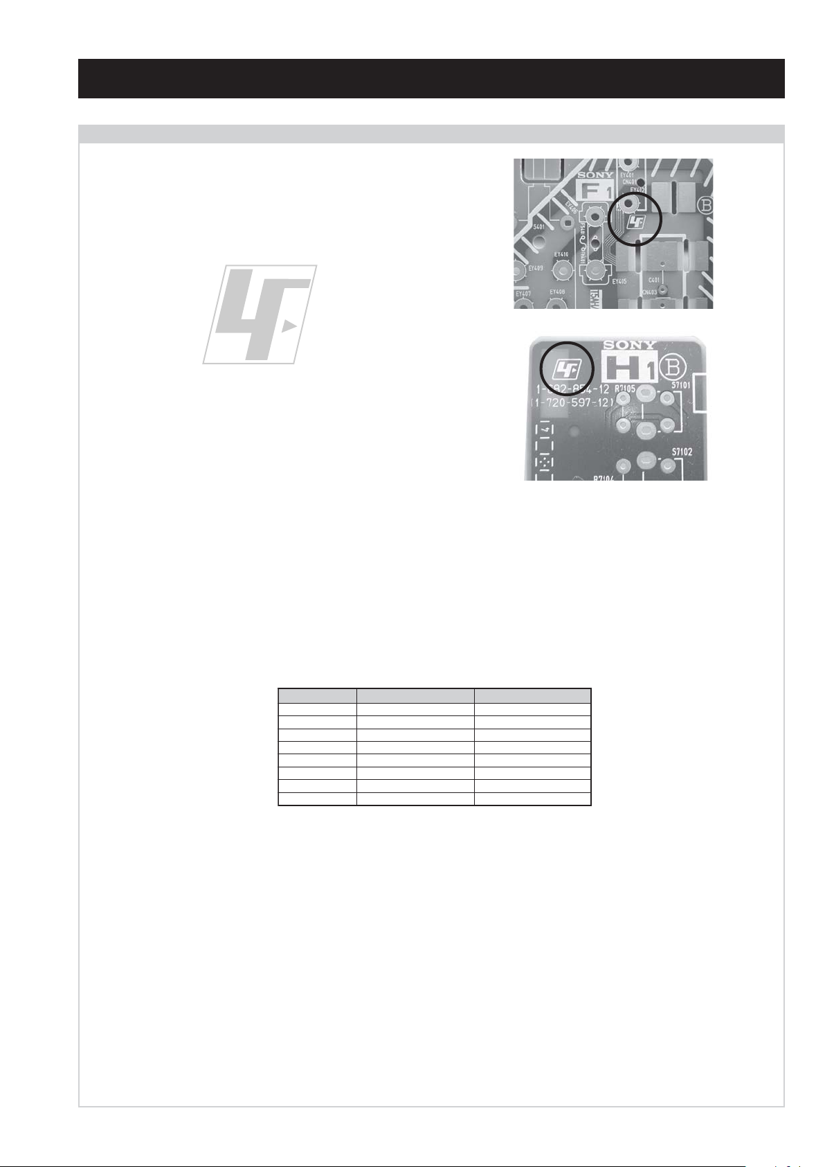
Lead Free Soldered Boards
The circuit boards used in these models have been processed using
Lead Free Solder. The boards are identified by the LF logo located
close to the board designation e.g. F1, H1 etc [ see examples ]. The
servicing of these boards requires special precautions to be taken as
outlined below.
SE-1
RM-ED007
example 1
example 2
It is strongly recommended to use Lead Free Solder material in order to guarantee optimal quality of new solder joints. Lead Free Solder is
available under the following part numbers :
rebmuntraP retemaiD skrameR
91-500-046-7mm3.0gK52.0
02-500-046-7mm4.0gK05.0
12-500-046-7mm5.0gK05.0
22-500-046-7mm6.0gK52.0
32-500-046-7mm8.0gK00.1
42-500-046-7mm0.1gK00.1
52-500-046-7mm2.1gK00.1
62-500-046-7mm6.1gK00.1
Due to the higher melting point of Lead Free Solder the soldering iron tip temperature needs to be set to 370 degrees centigrade. This requires
soldering equipment capable of accurate temperature control coupled with a good heat recovery characteristics.
For more information on the use of Lead Free Solder, please refer to http://www.sony-training.com
- 3 -
LEDOMMETI metsySnoisiveleT metsySoeretS egarevoClennahC metsySroloC
21E-20E:FHV
96E-12E:FHU
ET-BVD,L,I,K/D,H/G/B
MACIN/NAMREG
oeretS
02S-10S:VTAC
14S-12S:REPYH
R,21R-1R:K/D
96R-12
96F-12F,Q-B,01F-2F:L
96B-12BFHU:I
UT-BVD,IoeretSM
ACIN96B-12B:FHU
SE-1
RM-ED007
MACES,LAP
34.4/85.3CSTN
)YLNOOEDIV(
LM@PM2-GEPM
MACES,LAP
34.4/85.3CSTN
)YLNOOEDIV(
LM@PM2-GEPM
Sound Output
Right and Left speaker
Sub-woofer
Projected Picture Size
LCD (Liquid Crystal Display) Panel
KDL-26P2520/P2530 (26inches)
KDL-32P2520/P2530 (32inches)
KDL-40P2530 (40inches).
Input/Output Terminals [REAR] General Specifications
Power Requirements 220 - 240V
AV1: 21-pin Euro connector
(CENELEC standard)
Inputs for Audio and Video signals.
Inputs for RGB.
Outputs of TV Video and Audio signals.
Power Consumption/
Standby
Dimensions
Inputs for Audio and Video signals.
AV2: 21-pin Euro connector
(CENELEC standard)
Inputs for RGB.
Outputs of Video and Audio signals
(Selectable). SmartLink interface.
2 x 10W (RMS)
KDL-26P2520/P2530:
Approx. 100W or less/1W or less
KDL-32P2520/P2530:
Approx. 115W or less/1W or less
KDL-40P2530:
Approx. 190W or less/0.8W or less
KDL-26P2520/P2530:
Approx. 663x503x220mm (With stand)
Approx. 663x472x128mm (Without stand)
KDL-32P2520/P2530:
Approx. 797x580x220mm (With stand)
Approx. 797x548x125mm (Without stand)
KDL-40P2530:
Approx. 988x687x270mm (With stand)
Approx. 988x653x128mm (Without stand)
KDL-26P2520/P2530:
Approx. 12kg (With stand)
Approx. 10kg (Without stand)
KDL-32P2520/P2530:
Weight
Approx. 15kg (With stand)
Approx. 13kg (Without stand)
KDL-40P2530:
Approx. 24kg (With stand)
Approx. 21kg (Without stand)
RM-ED007 Remote Commander (1)
IEC designated R06 battery (2)
Cable Holder (1) (KDL-40P2530 only)
AV3: Phono Jacks
Y: 1 Vp-p, 75 ohms, 0.3V negative sync
B/CB
: 0.7 Vp-p, 75 ohms
P
P
R/CR
: 0.7 Vp-p, 75 ohms
Audio Input Jacks: 500mV rms,
47Kohms.
Supplied Accessories
Support Belt (1) and Screws (2)
HDMI Input HDMI Connectors.
PC Input 15 Pin D-Sub Connector. Mini jack.
CAM Conditional Access Module slot.
Other Features
IDTV, High Picture Quality WXGA, 3D Comb
Filter, BBE-ViVA, Virtual Dolby Surround,
2 HDMI Inputs, PC Input (HD15), Video Label,
Channel Return, Sleep Timer, Fanless Design.
Input/Output Terminals [SIDE] Remote control system : Infrared control
Headphone jack Stereo mini jack
Audio input Phono jacks
Video input Phono jack
S Video input 4 pin mini DIN
Power requirements
3V dc
2 batteries IEC designation
R06 (size AA)
Design and specifications are subject to change without notice.
- 4 -
SE-1
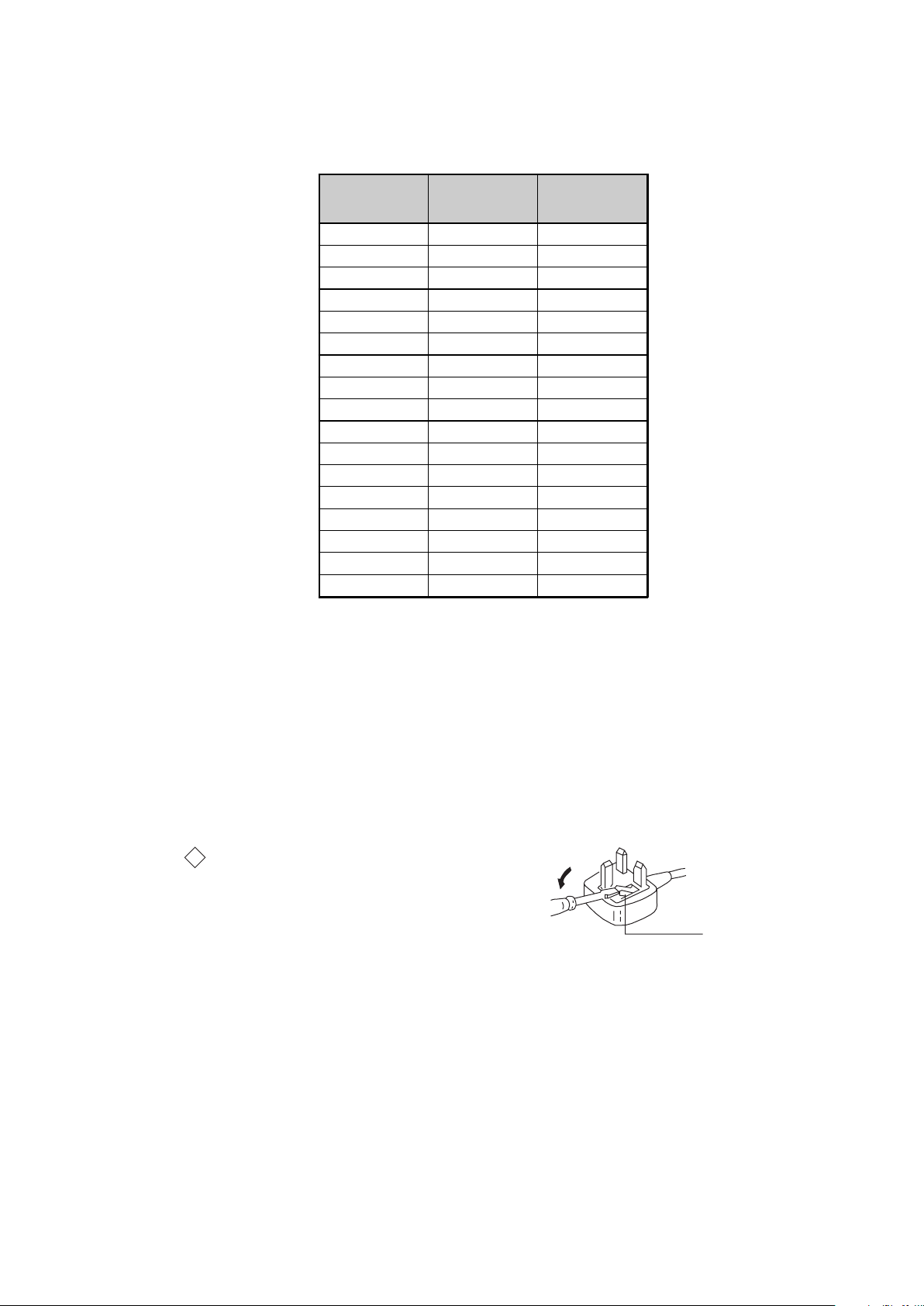
How to replace the fuse.
Open the fuse compartment with
a screwdriver blade and replace
the fuse.
FUSE
RM-ED007
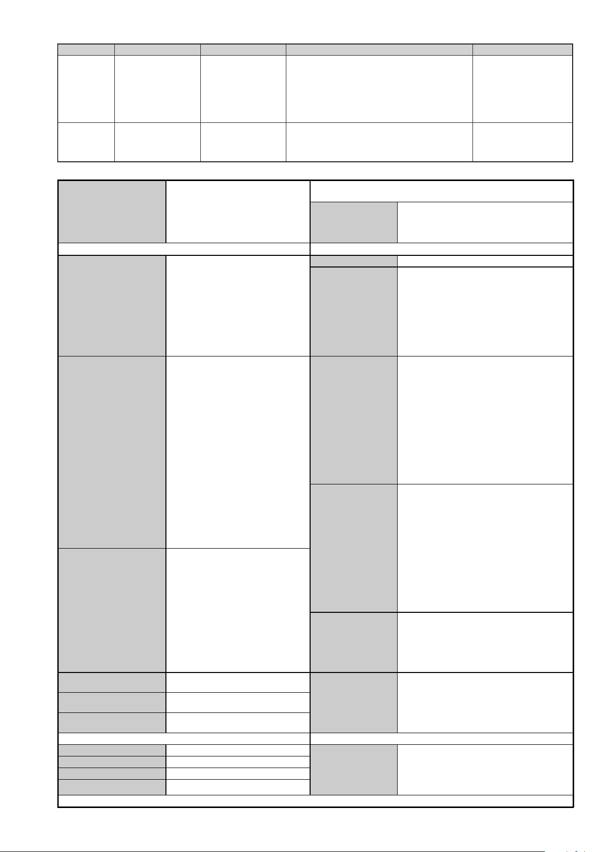
Model Name
Item
PA P O F F O F F
PAT O F F O F F
RGB Priority ON ON
Sub Woofer OFF OFF
Scart 1 ON ON
Scart 2 ON ON
Front in (4) ON ON
Projector OFF OFF
Norm B/G ON OFF
Norm I ON ON
Norm D/K ON OFF
Norm AUS OFF OFF
Norm L ON OFF
Norm SAT OFF OFF
Norm M OFF OFF
Teletext ON ON
Nicam Stereo ON ON
(AEP) (UK)
WARNING (UK Models only)
The flexible mains lead is supplied connected to a B.S. 1363 fused
plug having a fuse of 10 AMP rating. Should the fuse need to be
replaced, use a 10AMP FUSE approved by ASTA to BS 1362, ie one
that carries the
IF THE PLUG SUPPLIED WITH THIS APPLIANCE IS NOT SUITABLE FOR THE OUTLET SOCKETS IN YOUR HOME, IT SHOULD
BE CUT OFF AND AN APPROPRIATE PLUG FITTED. THE PLUG
SEVERED FROM THE MAINS LEAD MUST BE DESTROYED AS A
PLUG WITH BARED WIRES IS DANGEROUS IF ENGAGED IN A
LIVE SOCKET.
When an alternative type of plug is used, it should be fitted with a
10 AMP FUSE, otherwise the circuit should be protected by a
10AMP FUSE at the distribution board.
ASA
T
mark.
- 5 -

21 pin connector
21
19
17
15
13
11
9
7
5
3
1
20
18
16
14
12
10
8
6
4
2
Pin No 1 2 Signal Signal level
1 Audio output B
2
3
4 Ground (audio)
5 Ground (blue)
6 Audio input A
7 Blue input 0.7 +/- 3dB, 75 ohms positive
8 Function select
9 Ground (green)
10 AVlink
11 Green Green signal : 0.7 +/- 3dB, 75 ohms,
12 Open
13 Ground (red)
14 Ground (blanking)
15
_ (S signal Chroma
16 Blanking input
17 Ground (video
18 Ground (video
19 Video output 1V +/- 3dB, 75ohms, positive sync 0.3V
20
21 Common ground
(right)
Audio input B
(right)
Audio output A
(left)
(left)
(AV control)
_ _ Red input 0.7 +/- 3dB, 75 ohms, positive
-
-
input)
(Ys signal)
output)
input)
Video input 1V +/- 3dB, 75ohms, positive sync 0.3V
Video input
--
Y (S signal)
(plug, shield)
Standard level : 0.5V rms
Output impedence : Less than 1kohm*
Standard level : 0.5V rms
Output impedence : More than 10kohm*
Standard level : 0.5V rms
Output impedence : Less than 1kohm*
Standard level : 0.5V rms
Output impedence : More than 10kohm*
High state (9.5-12V) : Part mode
Low state (0-2V) : TV mode
Input impedence : More than 10K ohms
Input capacitance : Less than 2nF
positive
0.3 +/- 3dB, 75 ohms, positive
High state (1-3V) Low state (0-0.4V)
Input impedence : 75 ohms
(-3+10dB)
(-3+10dB)
1V +/- 3dB, 75ohms, positive sync 0.3V
(-3+10dB)
SE-1
RM-ED007
Connected Not Connected (open) * at 20Hz - 20kHz
Rear Connection Panel Side Connection Panel
S-Video
socket
niP
oN
1dnuorG-
2dnuorG-
3tupni)langisS(Y,mho57Bd3-/+V1
4tupni)langisS(CBd3-/+V3.0
langiS leveLlangiS
noitarugifnocniptekcosoediVS
V3.0.cnySevitisop
Bd01+3-
itisop,mho57
ev
.cnyS
- 6 -
SE-1
RM-ED007
SE-1 SELF DIAGNOSTIC SOFTWARE
The identification of errors within the SE-1 chassis is triggered in one of two ways :- 1: Busy or 2: Device failure to respond to IIC. In the event
of one of these situations arising the software will first try to release the bus if busy (Failure to do so will report with a continuous flashing
LED) and then communicate with each device in turn to establish if a device is faulty. If a device is found to be faulty the relevant device number
will be displayed through the LED (Series of flashes which must be counted).
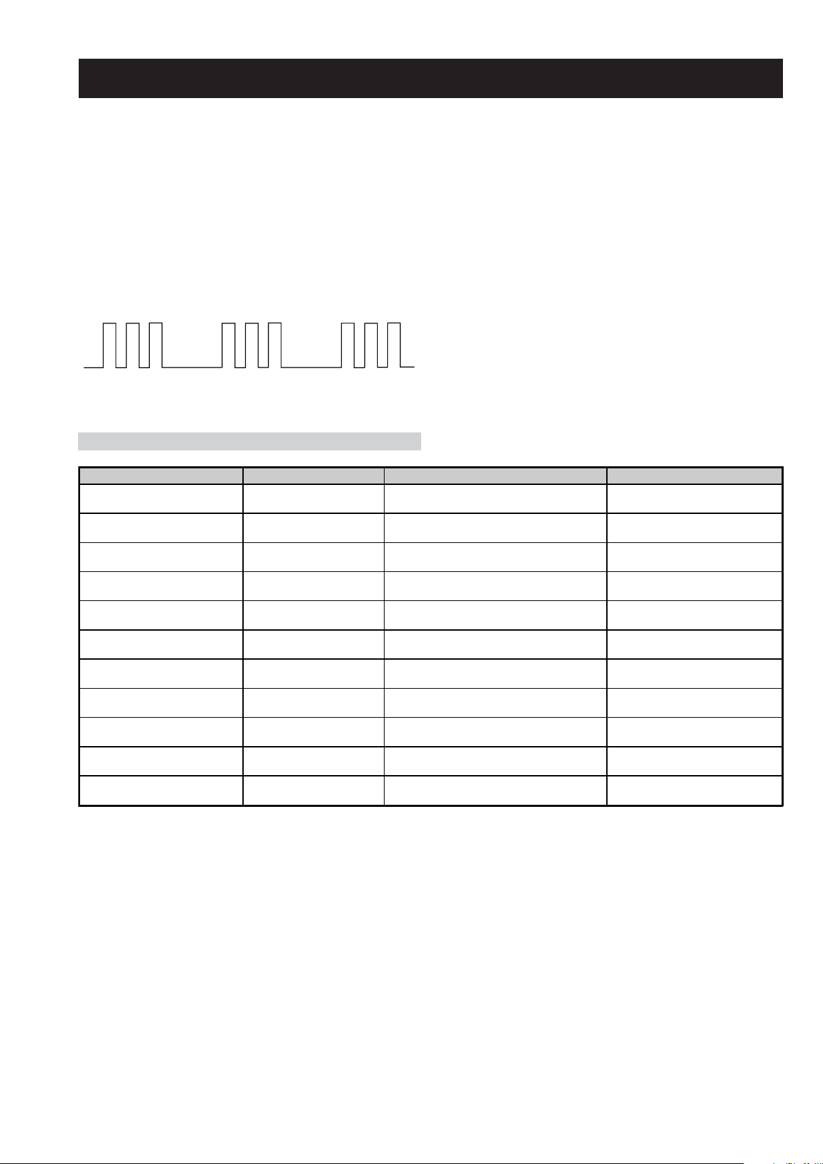
Flash Timing Example : e.g. error number 3
StBy LED
ON ON
OFF
OFF
LED Error Code
Error Message LED Code Checked Action
Power Supply Protection Error 03 In Normal mode.
Panel Error 04 In Normal mode.
NVM Error 05 In Initialisation state.
IIC Error 06 In Initialisation state.
HDMI Error 07 In Initialisation state.
Digital Error 08 In Initialisation state.
Tuner Error 09 In Initialisation state.
Sound Processor Error 10 In Initialisation state.
Video Processor (VCTP) Error 11 In Initialisation state.
Port Expander Error 12 In Initialisation state.
RTC IC Error 13 In Initialisation state.
Goes into standby. LED flashes 3
times.
Goes into standby. LED flashes 4
times.
Adds error to Error Menu. LED
flashes 5 times in factory mode.
Adds error to Error Menu. LED
flashes 6 times in factory mode.
Adds error to Error Menu. LED
flashes 7 times in factory mode.
Adds error to Error Menu. LED
flashes 8 times in factory mode.
Adds error to Error Menu. LED
flashes 9 times in factory mode.
Adds error to Error Menu. LED
flashes 10 times in factory mode.
Adds error to Error Menu. LED
flashes 11 times in factory mode.
Adds error to Error Menu. LED
flashes 12 times in factory mode.
Adds error to Error Menu. LED
flashes 13 times in factory mode.
- 7 -

SECTION 1 GENERAL
2
1
3
SE-1
RM-ED007
1 (standby)
1
2
3,4
2
Continued
from toppling over
3: Bundling the cables 4: Preventing the TV
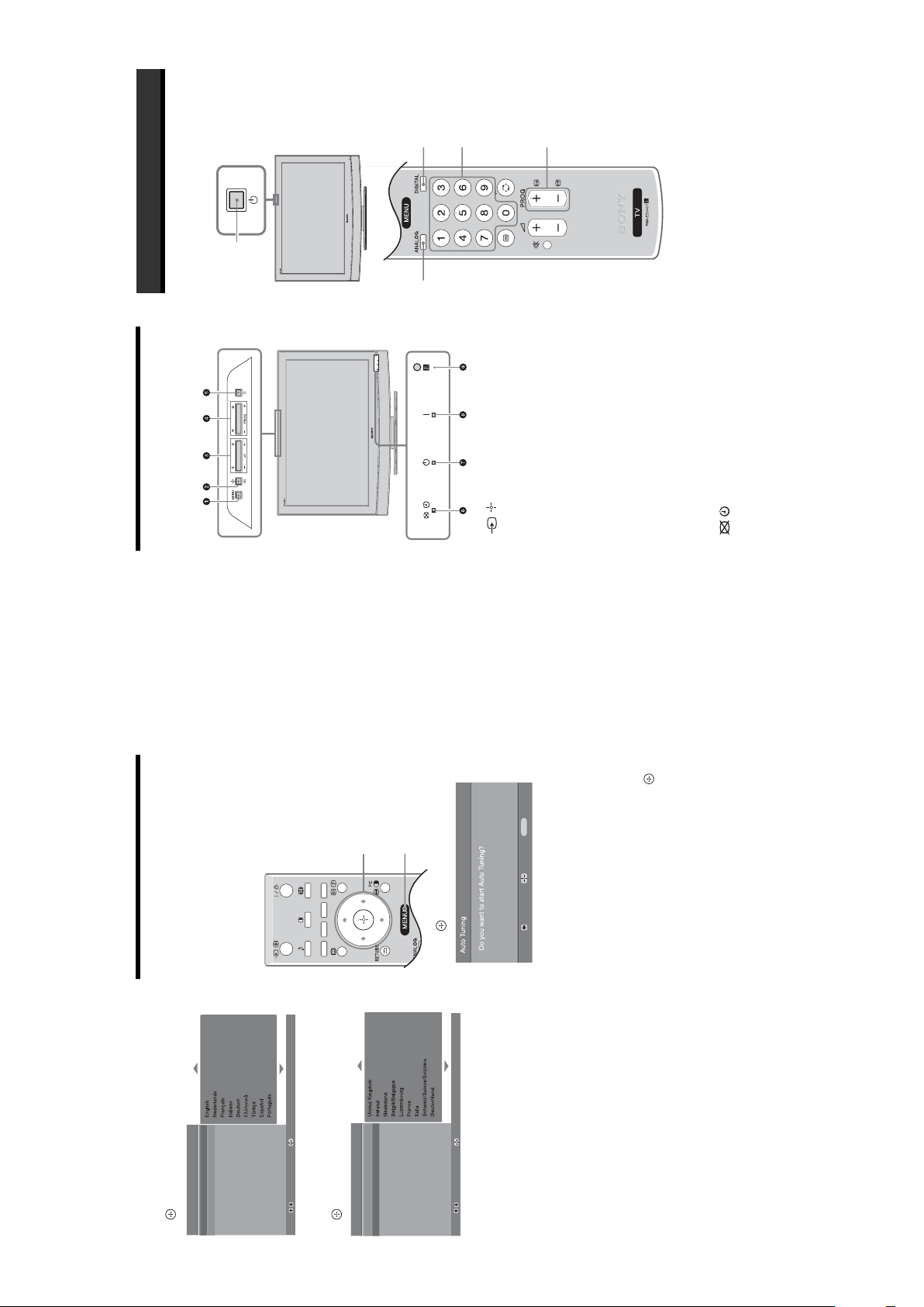
Selecting the language
and country/region
5:
(only for KDL-40U25xx)
indicator on the TV (front) is red), press "/1 on
(220-240V AC, 50Hz).
1 Connect the TV to your mains socket
2 Press 1 on the TV (top side).
the remote to switch on the TV.
When you switch on the TV for the first time, the
Language menu appears on the screen.
When the TV is in standby mode (the
The operating instructions mentioned here are partial abstracts
from the Operating Instruction Manual. The page numbers of
the Operating Instruction Manual remain as in the manual.
Coaxial cable (not supplied)
2: Connecting an aerial/
1: Checking the
Connecting an aerial only
VCR
accessories
Remote RM-ED007 (1)
Size AA batteries (R6 type) (2)
Cable holder (1) (only for KDL-40U25xx)
Support belt (1) and screws (2)
Connecting an aerial and VCR
To insert batteries into the remote
Scart lead (not supplied)
Certain regions may regulate disposal of the battery.
Please consult your local authority.
and new batteries.
spill liquid of any kind onto it.
Notes
• Do not use different types of batteries together or mix old
• Observe the correct polarity when inserting batteries.
• Dispose of batteries in an environmentally friendly way.
in a place subject to direct sunlight, or in a damp room.
• Handle the remote with care. Do not drop or step on it, or
• Do not place the remote in a location near a heat source, or
RF lead
(not supplied)
VCR
– 8 –
SE-1
3
Press
F
/
f
to select the language
displayed on the menu screens, then press
.
4
Press
F
/
f
to select the country/region in
which you will operate the TV, then press
.
If the country/region in which you want to use the
TV does not appear in the list, select “-” instead of
a country/region.
The message confirming the TV start auto-tuning
appears on the screen, then go to “6: Auto-tuning
the TV”.
6: Auto-tuning the TV
After selecting the language and country/region, a
message confirming the TV start auto-tuning appears
on the screen.
The TV will now search for and store all available TV
channels.
1
Press .
The TV starts searching for all available digital
channels, followed by all available analogue
channels. This may take some time, please be
patient and do not press any buttons on the TV or
remote.
If a message appears for you to confirm the aerial
connections
No digital or analogue channels were found.
Check all the aerial connections and press to
start auto-tuning again.
2
When the Programme Sorting menu
appears on the screen, follow the steps of
“Programme Sorting” (page 20).
If you do not wish to change the order in which the
analogue channels are stored on the TV, go to step
3.
3
Press MENU to exit.
The TV has now tuned in all the available
channels.
Auto Start Up
Language
Country
Select:
Confirm:
Auto Start Up
Language
Country
Select:
Confirm:
1
3
Back:
Start:
Cancel:
MENU
Overview of the TV
buttons and indicators
1 MENU (page 16)
2 / – Input select/OK
• In TV mode (page 23): Selects the input source
from equipment connected to the TV sockets.
• In TV menu: Selects the menu or option, and
confirm the setting.
3 2 +/-/
G
/
g
• Increases (+) or decreases (-) the volume.
• In TV menu: Moves through the options left (
G
)
or right (
g
).
4 PROG +/-/
F
/
f
• In TV mode: Selects the next (+) or previous (-)
channel.
• In TV menu: Moves through the options up (
F
) or
down (
f
).
5 1 – Power
Switches the TV on or off.
Note:
To disconnect the TV completely, pull the plug from
the mains.
6 – Picture Off/Timer indicator
• Lights up in green when the picture is switched off
(page 19).
• Lights up in orange when the timer is set
(page 20).
• Lights up in red when digital REC starts in standby
mode.
7 1 – Standby indicator
Lights up in red when the TV is in standby mode.
8 " – Power indicator
Lights up in green when the TV is switched on.
9 Remote control sensor
Watching TV
1
Press 1 on the TV (top side) to switch on
the TV.
When the TV is in standby mode (the 1 (standby)
indicator on the TV (front) is red), press "/1 on
the remote to switch on the TV.
2
Press DIGITAL to switch to digital mode or
ANALOG to switch to analogue mode.
The channels available vary depending on the
mode.
3
Press the number buttons or PROG +/- to
select a TV channel.
Watching TV
3
1
2
2
3
1
RM-ED007
– 9 –
SE-1
Checking the Digital Electronic Programme Guide
(EPG)
1
In digital mode, press to display the
Digital Electronic Programme Guide
(EPG).2Perform the desired operation, as shown in
the following table.
Note
Programme information will only be displayed if the TV
station is transmitting it.
Digital Electronic Programme Guide (EPG)
To Do this
Watch a current programme Press while the current programme is selected.
Sort the programme information by
category – Category list
1 Press the blue button.
2 Press
F
/
f
/
G
/
g
to select a category. The category name is
displayed on the side.
3 Press .
The Digital Electronic Programme Guide (EPG) now only displays the
current programmes from the category selected.
Set a programme to be recorded – Timer
REC
1 Press
F
/
f
/
G
/
g
to select the future programme you want to
record.
2 Press .
3 Press
F
/
f
to select “Timer REC”.
4 Press to set the TV and your VCR timers.
A symbol appears by that programme’s information. The
indicator on the TV (front) lights up.
Set a programme to be displayed
automatically on the screen when it starts
– Reminder
1 Press
F
/
f
/
G
/
g
to select the future programme you want to
display.
2 Press .
3 Press
F
/
f
to select “Reminder”.
4 Press to automatically display the selected programme
when the programme starts.
A c symbol appears by that programme’s information.
Note
If you switch the TV to standby mode, it will automatically turn itself on
when the programme is about to start.
Set the time and date of a programme you
want to record – Manual timer REC
1 Press .
2 Press
F
/
f
to select “Manual timer REC”, then press .
3 Press
F
/
f
to select the date, then press
g
.
4 Set the start and stop time in the same way as in step 3.
5 Press
F
/
f
to select the programme, then press to set the
TV and your VCR timers.
A symbol appears by that programme’s information. The
indicator on the TV (front) lights up.
RM-ED007
MENU
Exit:
.
g
/
G
Enter:
to select an option.
f
/
Digital Favourites
F
/
f
/
F
Press MENU to display the menu.2Press
1
2,3
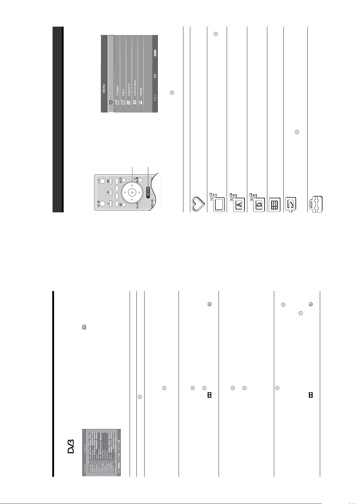
Using MENU Functions
Navigating through menus
“MENU” allows you to enjoy various convenient features of this TV. You can easily select channels or external
inputs with the remote. Also, settings for your TV can be changed easily using “MENU”.
Press to confirm a selected option.
Select:
To exit the menu, press MENU.
3
Launches the Favourite list. For details about settings, see page 15.
Allows you to select TV programs from a list of channel labels.
• To watch the desired channel, select the channel, then press .
• To assign a label to a program, see page21.
Returns to the last viewed analogue channel.
Returns to the last viewed digital channel.
Selects equipment connected to your TV.
press .
• To watch the desired external input, select the input source, then
• To assign a label to an external input, see page 20.
Opens the Settings menu screen where most of advanced settings and
adjustments are performed. Select a menu icon, select an option and make the
desired change or adjustment using
For details about settings, see page 17 to 22.
Launches the Digital Electronic Programme Guide (EPG).
For details about settings, see page 14.
1
(in digital mode only)
(in digital mode only)
Digital Favourites
Menu Description
Programme List
(in analogue mode
only)
Analogue
Digital
(in digital mode only)
Digital EPG
(in digital mode only)
External Inputs
Settings
– 10 –
SE-1
Picture Adjustment menu
You can select the options listed below on the
Picture menu. To select options in “Settings”,
see “Navigating through menus” (page 16).
Picture Mode
Selects the picture mode.
• “Vivid”: For enhanced picture contrast and sharpness.
• “Standard”: For standard picture. Recommended for home entertainment.
• “Custom”: Allows you to store your preferred settings.
Backlight
Adjusts the brightness of the backlight.
Contrast
Increases or decreases picture contrast.
Brightness
Brightens or darkens the picture.
Colour
Increases or decreases colour intensity.
Hue
Increases or decreases the green tones.
Tip
“Hue” can only be adjusted for an NTSC colour signal (e.g., U.S.A. video tapes).
Sharpness
Sharpens or softens the picture.
Colour Tone
Adjusts the whiteness of the picture.
• “Cool”: Gives the white colours a blue tint.
• “Neutral”: Gives the white colours a neutral tint.
• “Warm”: Gives the white colours a red tint.
Tip
“Warm” can only be selected when you set “Picture Mode” to “Custom”.
Reset
Resets all picture settings except “Picture Mode” to the factory settings.
Noise Reduction
Reduces the picture noise (snowy picture) in a weak broadcast signal.
• “Auto”: Automatically reduces the picture noise.
• “High/Mid/Low”: Modifies the effect of the noise reduction.
Picture Adjustment
Select:
Enter:
Exit:
MENU
Picture Mode
Backlight
Contrast
Brightness
Colour
Hue
Sharpness
Colour Tone
Reset
Noise Reduction
Custom5Max5050015
Warm
Auto
Back:
Sound Adjustment menu
You can select the options listed below on the
Sound menu. To select options in “Settings”,
see “Navigating through menus” (page 16).
Sound Effect
Selects the sound mode.
•
“
Standard”: Enhances clarity, detail, and sound presence by using “BBE High definition
Sound System.”
• “Dynamic”: Intensifies clarity and sound presence for better intelligibility and musical
realism by using the “BBE High definition Sound System.”
.“BBE ViVA”: BBE ViVA Sound provides musically accurate natural 3D image with Hi-Fi
sound. The clarity of the sound is improved by BBE while the width depth and height of sound
image are expanded by BBE’s proprietary 3D sound process. BBE ViVA Sound is compatible
with all TV programs including news, music, dramas, movies, sports and electronic games.
Treble
Adjusts higher-pitched sounds.
Bass
Adjusts lower-pitched sounds.
Balance
Emphasizes left or right speaker balance.
Reset
Resets all the sound settings to the factory settings.
Dual Sound
Selects the sound from the speaker for a stereo or bilingual broadcast.
• “Stereo”, “Mono”: For a stereo broadcast.
• “A”/“B”/“Mono”: For a bilingual broadcast, select “A” for sound channel 1, “B”
for sound channel 2, or “Mono” for a mono channel, if available.
Tip
If you select other equipment connected to the TV, set “Dual Sound” to “Stereo”, “A” or “B”.
Auto Volume
Keeps a constant volume level even when volume level gaps occur (e.g., adverts tend
to be louder than programmes).
TV Speakers
Turns off the TV speakers e.g. to listen to the sound through external audio
equipment connected to the TV.
• “On”: the sound is output from the TV speakers.
• “One Time Off”: the TV speakers are temporarily turned off allowing you to listen
to the sound from external audio equipment.
• “Permanent Off”: the TV speakers are permanently turned off allowing you to
listen to the sound from external audio equipment.
Tips
• To turn on the TV speakers again, change to on.
• The “One Time Off” option automatically returns to “On” when the TV set is
switched off.
• "Sound Adjustment" options are not available if "One Time Off" or "Permanent
Off" have been selected.
Sound Adjustment
Sound Effect
Tre bl e
Bass
Balance
Reset
Dual Sound
Auto Volume
TV Speakers
Standard50500MonoOnOn
Select:
Enter:
Exit:
MENU
Back:
RM-ED007
– 11 –
Features menu
You can select the options listed below on the
Features menu. To select options in “Settings”,
see “Navigating through menus” (page 16).
Screen
Changes the screen format.
• “Auto Format”: Automatically changes the screen format according to the
broadcast signal.
• “Screen Format”: For details about the screen format, see page 13
• “Vertical Size”: Adjusts the vertical size of the picture when the screen format is
set to Smart.
Tips
• Even if you have selected “On” or “Off” in “Auto Format”, you can always modify the
format of the screen by pressing repeatedly.
• “Auto Format” is available for PAL and SECAM signals only.
Power Saving
Selects the power saving mode to reduce the power consumption of the TV.
• “Standard”: Default settings.
• “Reduce”: Reduces the power consumption of the TV.
• “Picture Off”: Switches off the picture. You can listen to the sound with the picture
off.
Adv. Contrast
Enhancer
Automatically adjusts "Backlight" to the most suitable settings judging from the
brightness of the picture. It will increase the contrast distinction of the picture.
AV2 Output
Sets a signal to be output through the socket labelled / 2 on the rear of the
TV. If you connect a VCR to the / 2 socket, you can then record from the
equipment connected to other sockets of the TV.
• “TV”: Outputs a broadcast.
•“Auto”: Outputs whatever is being viewed on the screen (except signals from the
/ 3, HDMI IN 6, HDMI IN 7 and PC sockets).
RGB Center
Adjusts the horizontal picture position so that the picture is in the middle of the
screen.
Tip
This option is only available if an RGB source has been connected to the Scarts connectors
1/ 1
or
2/ 2
on the rear of the TV.
PC Adjustment
Customizes the TV screen as a PC monitor.
Tip
This option is only available if you are in PC Mode.
• “Phase”: Adjust the screen when a part of a displayed text or image is not clear.
• “Pitch”: Enlarges or shrinkes the screen size horizontally.
• “H Center”: Moves the screen to the left or to the right.
• “V Lines”: Corrects the picture lines while viewing an RGB input signal from the
PC connector.
• “Power saving”: Turns to standby mode if no PC signal is received.
• “Reset”: Resets to the factory settings.
Features
StandardOnTV
0
Select:
Enter:
Exit:
MENU
Back:
Screen
Power Saving
Adv. Contrast Enhancer
AV
2 Output
RGB Center
PC Adjustment
Timer
You can select the options listed below on the
Set-up menu. To select options in “Settings”, see
“Navigating through menus” (page 16).
SE-1
RM-ED007
Sets a period of time after which the TV automatically switches itself into standby
When the Sleep Timer is activated, the (Timer) indicator on the TV (front)
mode.
Sets the timer to turn on/off the TV.
• Sleep Timer
lights up in orange.
Timer
before the TV switches to standby mode.
Tips
• If you switch off the TV and switch it on again, “Sleep Timer” is reset to “Off”.
Allows you to adjust the clock manually. When the TV is receiving digital
• “Sleep timer will end soon. Power will be turned off” appears on the screen one minute
• Clock Set
Sets the timer to turn on/off the TV.
“Timer Mode”: Selects the desired period.
“On Time”: Sets the time to turn on the TV.
channels, the clock cannot be adjusted manually since it is set to the time code of
the broadcasted signal.
•Timer
“Off Time”: Sets the time to turn off the TV.
Set-up menu
.
g
to select the channel you want to move to a new position,
to select the new position for your channel, then press .
f
f
/
/
F
MENU
Exit:
F
then press
English
-
AV Preset
System Information
Auto Start Up
Set Up
Sound Offset
Language
Country
Auto Tuning
Programme Sorting
Displays the current software version and the signal level.
Starts the “first time operation menu” to select the language and country/region, and
tune in all available digital and analogue channels.
Selects the language in which the menus are displayed.
Selects the country/region where you operate the TV.
Tip
The country/region in which you want to use the TV does not appear in the list, select
“-” instead of a country/region.
Tunes in all the available analogue channels.
Enter:
Select:
Digital Set Up
Manual Programme Preset
Back:
System Information
Auto Start-up
Language
Country
Auto Tuning
2 Press
Changes the order in which the analogue channels are stored on the TV.
1 Press
Assigns a name to any equipment connected to the side and rear sockets.
Programme Sorting
AV Preset
”: Uses one of the preset labels to assign a name to connected
to select the desired input source, then press .
to select the desired option below, then press .
f
f
/
/
F
F
AV1 (or AV2/ AV3/ AV4/ PC/ HDMI 1/HDMI 2), VIDEO, DVD, CABLE, GAME,
CAM, SAT
equipment.
press F/f to select the input source.
• “Edit”: Creates your own label.
• “Skip”: Skips an input source that is not connected to any equipment when you
2 Press
1 Press
•“
– 12 –
SE-1
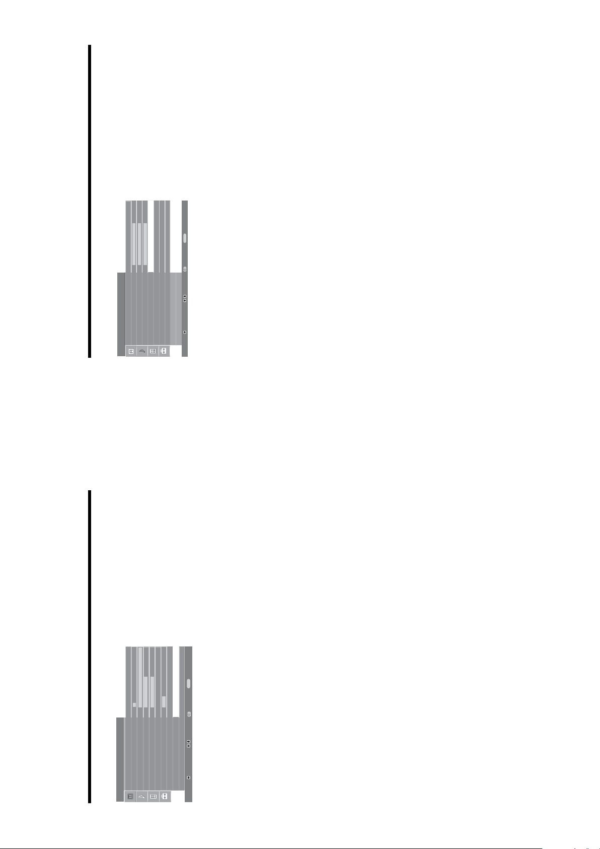
Digital Set-up menu
You can change/set the digital settings using the
Digital Set-up menu. To select options in
“Settings”, see “Navigating through menus”
(page 16).
Digital Tuning
Displays the “Digital Tuning” menu.
Digital Auto Tuning
Tunes in all the available digital channels..
Programme List Edit
Removes any unwanted digital channels stored on the TV, and changes the order of
the digital channels stored on the TV.
Digital Manual Tuning
Tunes the digital channels manually.
Digital Set-up
Displays the “Digital Set Up” menu.
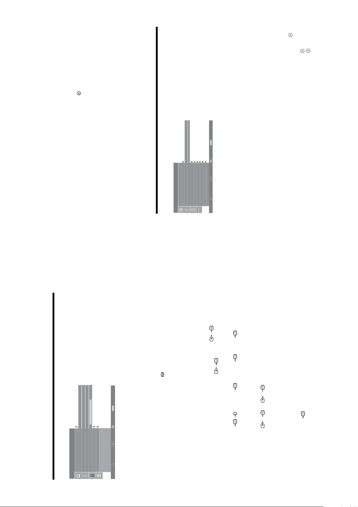
Subtitle Setting
Displays digital subtitles on the screen.
Subtitle Language
Selects which language subtitles are displayed in.
Audio Language
Selects the language used for a programme.
Audio Type
Increases the sound level when “For Hard Of Hearing” is selected.
Parental Lock
Sets an age restriction for programmes
PIN Code
Sets a PIN code for the first time, or allows you to change your PIN code.
Tip
PIN code 9999 is always accepted.
Technical Set-up
Displays the Technical Set-up menu.
“Auto Service Update”: Enables the TV to detect and store new digital services as
they become available.
“Software Download”: Enables the TV to automatically receive software updates,
free through your existing aerial (when issued). Sony recommends that this option is
set to “On” at all times. If you do not want your software to be updated, set this option
to “Off”.
“System Information”: Displays the current software version and the signal level.
“Time Zone”: Allows you to select the correct time zone for your country.
CA Module Set-up
Allows you to access a Pay Per View service once you obtain a Conditional Access
Module (CAM) and a view card. See page 23 for the location of the (PCMCIA)
socket.
Set Up
Select:
Enter:
Exit:
MENU
English
-
Back:
Auto Start Up
Language
Country
Auto Tuning
Programme Sorting
AV Preset
Sound Offset
Manual Programme Preset
Digital Set Up
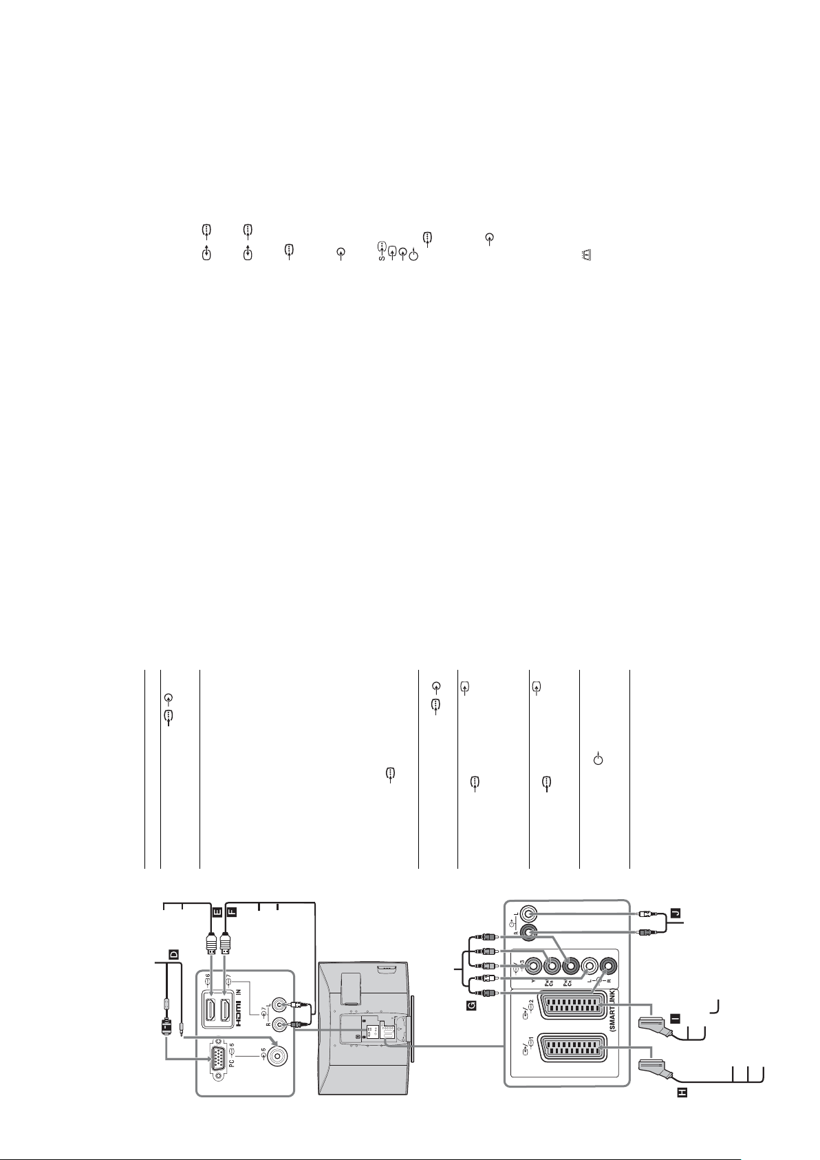
Connecting optional equipment
Using Optional Equipment
You can connect a wide range of optional equipment to your TV. Connecting cables are not supplied.
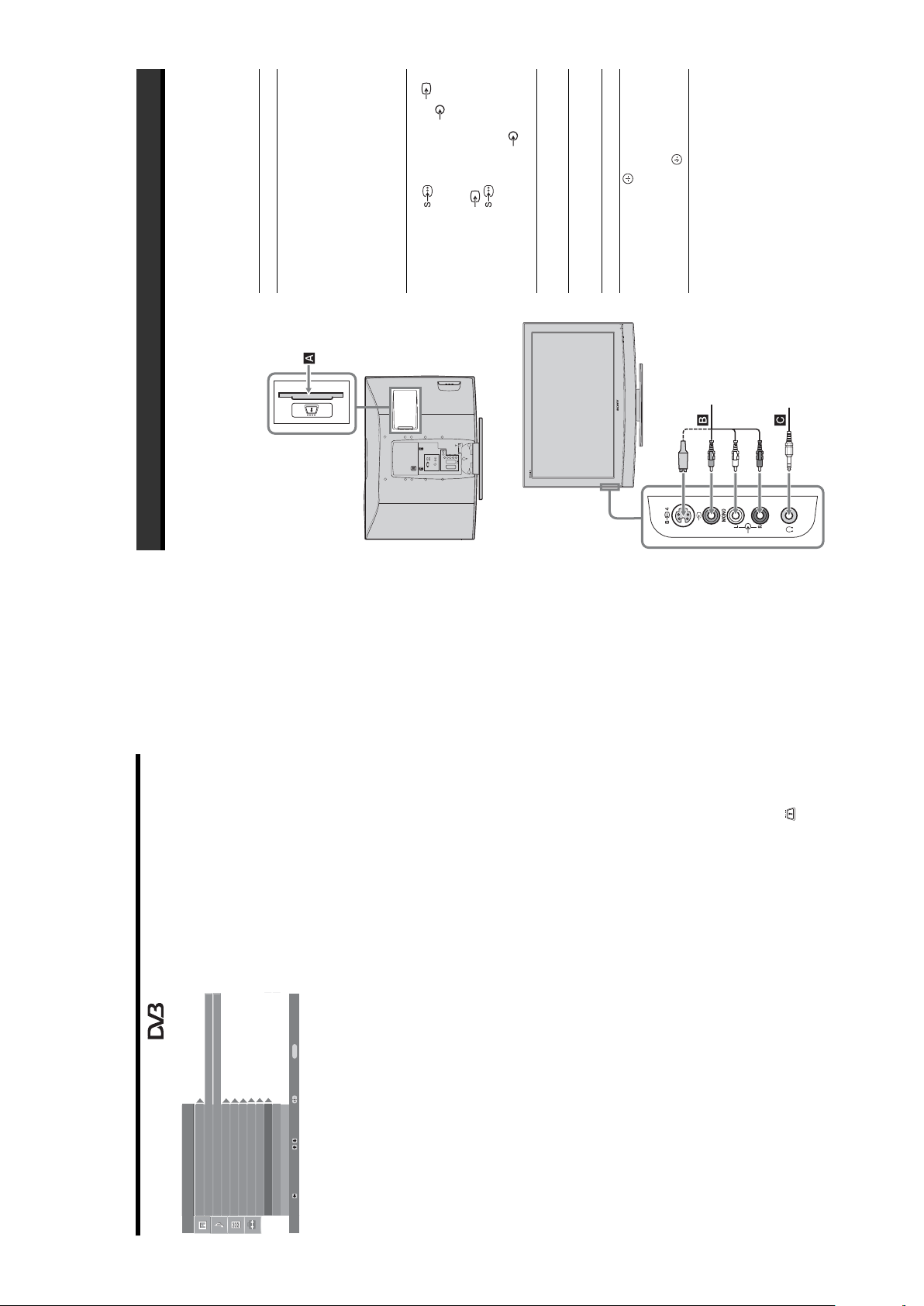
Connecting to the TV (side)
Headphones
S VHS/Hi8/DVC
camcorder
To connect Do this
Conditional Access
Module (CAM) A
To use Pay Per View services.
For details, refer to the instruction
manual supplied with your CAM.
To use the CAM, remove the
rubber cover from the CAM slot.
Switch off the TV when inserting
your CAM into the CAM slot.
When you do not use the CAM, we
recommend that you replace the
cover on the CAM slot.
S VHS/Hi8/DVC
camcorder B
Connect to the S video socket
4 or the video socket 4,
and the audio sockets 4. To
avoid picture noise, do not connect
the camcorder to the video socket
4 and the S video socket
4 at the same time. If you
connect mono equipment, connect
to the L socket 4, and set
“Dual Sound” to “A” (page 18).
Headphones C Connect to the i socket to listen to
sound from the TV on headphones.
Additional operations
To Do this
Access the Input
signal index table
Press to access the Input signal
index table. (Then, only in
analogue mode, press
g
.) To
select an input source, press
F
/
f
,
then press .
RM-ED007
– 13 –
CATV: S1–S20
HYPER: S21–S41
D/K: R1–R12, R21–R69
L: F2–F10, B–Q, F21–F69
I: UHF B21–B69
/1
Terminals
Digital: VHF/UHF
B/CB: 0.7 Vp-p, 75 ohms
/ 2 (SMARTLINK)
21-pin Scart connector (CENELEC standard) including
audio/video input, RGB input, and TV audio/video
output.
3
21-pin Scart connector (CENELEC standard) including
audio/video input, RGB input, selectable audio/video
output, and SMARTLINK interface.
R/CR: 0.7 Vp-p, 75 ohms
P
3
Supported formats: 1080i, 720p, 576p, 576i, 480p, 480i
Y: 1 Vp-p, 75 ohms, 0.3V negative sync
P
4 S video input (4-pin mini DIN)
Audio input (phono jacks)
500 mVrms
Impedance: 47 kilo ohms
Audio output (Left/Right) (phono jacks)
4 Video input (phono jack)
4 Audio input (phono jacks)
G: 0.7 Vp-p, 75 ohms, non Sync on Green
B: 0.7 Vp-p, 75 ohms, non Sync on Green
PC PC Input (15 Dsub) (see page 24)
PC audio input (minijack)
R: 0.7 Vp-p, 75 ohms, non Sync on Green
HD: 1-5 Vp-p
VD: 1-5 Vp-p
32, 44.1 and 48 kHz, 16, 20 and 24 bits
500 mVrms, Impedance 47 kilohms
(HDMI IN 7 only)
Video: 1080i, 720p, 576p, 576i, 480p, 480i
Audio: Two channel linear PCM
Analogue audio (phono jacks):
CAM (Conditional Access Module) slot
HDMI IN 6, 7
i Headphones jack
KDL-40P25xx: 10 W + 10 W (RMS)
KDL-32P25xx: 10 W + 10 W (RMS)
KDL-26P25xx: 10 W + 10 W (RMS)
Sound Output
Supplied Accessories
SU-WL51 (for KDL-40P25xx)
Refer to “1: Checking the accessories” on page 4.
Optional Accessories
• Wall-Mount Bracket
SE-1
RM-ED007
SU-WL31 (for KDL-32P25xx / KDL-26P25xx)
Design and specifications are subject to change
without notice.
220–240 V AC, 50 Hz
KDL-40P25xx: 40 inches
KDL-32P25xx: 32 inches
KDL-26P25xx: 26 inches
1,366 dots (horizontal) × 768 lines (vertical)
Specifications
Display Unit
Power Requirements:
Screen Size:
Display Resolution:
sockets. It is recommended to use
a PC cable with ferrites.
Connect to the HDMI IN 6 or 7
socket if the equipment has a
HDMI socket. The digital video
and audio signals are input from
KDL-40P25xx: 190 W or less
KDL-32P25xx: 115 W or less
KDL-26P25xx: 100 W or less
KDL-40P25xx: 0.8 W or less
Power Consumption:
the equipment. If the equipment
Standby Power Consumption*:
has a DVI socket, connect the DVI
socket to the HDMI IN 7 socket
through a DVI - HDMI adaptor
interface (not supplied), and
finishes necessary internal processes.
KDL-32P25xx: 1 W or less
KDL-26P25xx: 1 W or less
* Specified standby power is reached after the TV
connect the equipment’s audio out
sockets to the audio in HDMI IN 7
sockets.
Notes
• The HDMI sockets only support
Approx. 988 × 687 × 270 mm (with stand)
Approx. 988 × 653 × 128 mm (without stand)
Approx. 797 × 580 × 220 mm (with stand)
Approx. 797 × 548 × 125 mm (without stand)
Approx. 663 × 503 × 220 mm (with stand)
Approx. 663 × 472 × 128 mm (without stand)
KDL-40P25xx:
KDL-32P25xx:
KDL-26P25xx:
Dimensions (w × h × d):
socket.
the following video inputs: 480i,
480p, 576i, 576p, 720p and 1080i.
To connect a PC, please use the PC
cable that bears the HDMI logo.
• Be sure to use only an HDMI
Connect to the component sockets
Mass:
and the audio sockets / 3.
Connect to the scart socket /
Approx. 24 kg (with stand)
Approx. 21 kg (without stand)
Approx. 15 kg (with stand)
Approx. 13 kg (without stand)
KDL-40P25xx:
KDL-32P25xx:
KDL-26P25xx:
1. When you connect the
decoder, the scrambled signal from
the TV tuner is output to the
decoder, then the unscrambled
signal is output from the decoder.
Connect to the scart socket /
B/G/H, D/K, L, I
Approx. 12 kg (with stand)
Approx. 10 kg (without stand)
Panel System
LCD (Liquid Crystal Display) Panel
TV System
Analogue: Depending on your country/region selection:
2. SMARTLINK is a direct
link between the TV and a VCR/
DVD recorder.
Connect to the audio output
sockets to listen to the sound
from the TV on Hi-Fi audio
equipment.
NTSC 3.58, 4.43 (only Video In)
Digital: DVB-T
Colour/Video System
Analogue: PAL, SECAM
Digital: MPEG-2 MP@ML
UHF: E21–E69
Aerial
75 ohm external terminal for VHF/UHF
Channel Coverage
Analogue: VHF: E2–E12
To connect Do this
PC D Connect to the PC /
Digital satellite
receiver or DVD
player E, F
DVD
player
Digital
satellite
receiver
PC
Connecting to the TV (rear)
DVD
player
Digital
satellite
receiver
DVD player with
component output
– 14 –
DVD player
G
Video game
equipment, DVD
player or decoder
H
with component output
DVD recorder or
VCR that supports
SmartLink I
Hi-Fi audio
equipment J
Hi-Fi
Decoder
VCR
DVD recorder
DVD player
Decoder
Video game equipment
jacks of 3.
R
/C
R
, P
B
jacks of 3 are firmly seated in their
R
/C
B
/C
R
, P
B
/C
B
SE-1
RM-ED007
(Automatic Fine Tuning) to obtain better picture reception (page 21).
bright points (pixels) on the screen do not indicate a malfunction.
• Select “Manual Programme Preset” in the “Set-Up” menu and adjust “AFT”
• The picture of a display unit is composed of pixels. Tiny black points and/or
• Select “Reset” in the “Picture Adjustment” menu to return to the factory
Problem Cause/Remedy
Picture noise when viewing a
Some tiny black points and/or
bright points on the screen
TV channel
No colour on programmes
settings (page 17).
• Check the connection of the Y, P
No colour or irregular colour
respective sockets.
• Make sure that the Y, P
jacks of 3
R
/C
R
, P
B
/C
B
when viewing a signal from the
Y, P
resolution to 720p and adjust horizontal and vertical screen size in the
• Check PC input socket connection.
Irregular picture when viewing
display properties settings of PC.
• Connect to PC input socket instead of HDMI IN 6, 7 socket.
• If the connection is only available through HDMI socket, change the screen
a signal from PC
Sound
Problem Cause/Remedy
•Press 2 +/– or % (Mute).
• Check that “TV Speakers” is set to “On” in the “Sound Adjustment” menu
No sound, but good picture
Standard
(page 18).
• See the “Picture noise” causes/remedies on page 27.
Noisy sound
analogue channel.
service.
• Switch between digital and analogue mode and select the desired digital/
• Scrambled/Subscription only channel. Subscribe to the Pay Per View
Channels
Problem Cause/Remedy
The desired channel cannot be
selected
Some channels are blank
equipment).
your area.
• Check that the aerial is plugged directly into the TV (not through other
• Channel is used only for data (no picture or sound).
• Contact the broadcaster for transmission details.
• Contact a local installer to find out if digital transmissions are provided in
• Upgrade to a higher gain aerial.
Digital channel is not displayed
General
Problem Cause/Remedy
• Check if the “Sleep Timer” is activated, or confirm the setting of “Off
The TV turns off automatically
Time” (page 20).
10 minutes, the TV automatically switches to standby mode.
• If no signal is received and no operation is performed in the TV mode for
(the TV enters standby mode)
source (page 20).
• Check if the “On Time” is activated (page 20).
• Select “AV Preset” in the “Set-up” menu and cancel “Skip” of the input
• Replace the batteries.
selected
The TV turns on automatically
Some input sources cannot be
The remote does not function
Ver tic al
frequency (Hz)
Horizontal
frequency (kHz)
Signals Horizontal (Pixel) Vertical (Line)
VGA 640 480 31.5 60 VGA
SVGA 800 600 37.9 60 VESA Guidelines
XGA 1024 768 48.4 60 VESA Guidelines
PC Input Signal Reference Chart
WXGA 1280 768 47.4 60 VESA
the correct input symbol is displayed on the screen.
•If the 1 (standby) indicator lights up in red, press "/1.
• Check the aerial connection.
• Connect the TV to the mains, and press 1 on the TV (top side).
No picture (screen is dark) and
no sound
• Check that the optional equipment is on and press / repeatedly until
No picture or no menu
have your TV serviced by qualified service personnel.
1280 768 47.8 60 VESA
For example, the indicator flashes for two seconds, stops flashing for one second, and flashes for two seconds.
message “NO SYNC”.
• This TV’s PC input does not support Sync on Green or Composite Sync.
• This TV’s PC input does not support interlaced signals.
• This TV’s PC input supports signals in the above chart with a 60 Hz vertical frequency. For other signals, you will see the
Troubleshooting
Check whether the 1 (standby) indicator is flashing in red.
When it is flashing
The self-diagnosis function is activated.
Sony service centre of how the indicator flashes (duration and interval).
1 Measure how long the 1 (standby) indicator flashes and stops flashing.
2 Press 1 on the TV (top side) to switch it off, disconnect the mains lead, and inform your dealer or
When it is not flashing
Picture
1 Check the items in the tables below.
2 If the problem still persists,
Problem Cause/Remedy
changing the resolution, some dots can appear blinking on the screen for a
• Check the connection between the optional equipment and the TV.
• When connecting any equipment to the HDMI IN 6, 7 socket or when
information from equipment
connected to the scarts or
HDMI IN socket
– 15 –
years in normal use, one to two years at the seaside).
few seconds. HDMI signal decoding is in progress and it does not indicate a
malfunction.
• Check aerial/cable connections.
• Check the aerial location and direction.
• Check if the aerial is broken or bent.
Double images or ghosting
Only snow and noise appear
hair-dryers or optical equipment.
• Check if the aerial has reached the end of its serviceable life (three to five
on the screen
equipment and the TV.
• Keep the TV away from electrical noise sources such as cars, motorcycles,
• When installing optional equipment, leave some space between the optional
Distorted picture (dotted lines
or stripes)
• Make sure that the aerial is connected using the supplied coaxial cable.
• Keep the aerial cable away from other connecting cables.
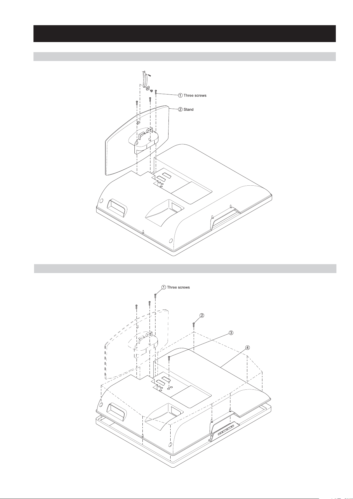
2-1. STAND REMOVAL
SE-1
RM-ED007
SECTION 2 DISASSEMBLY
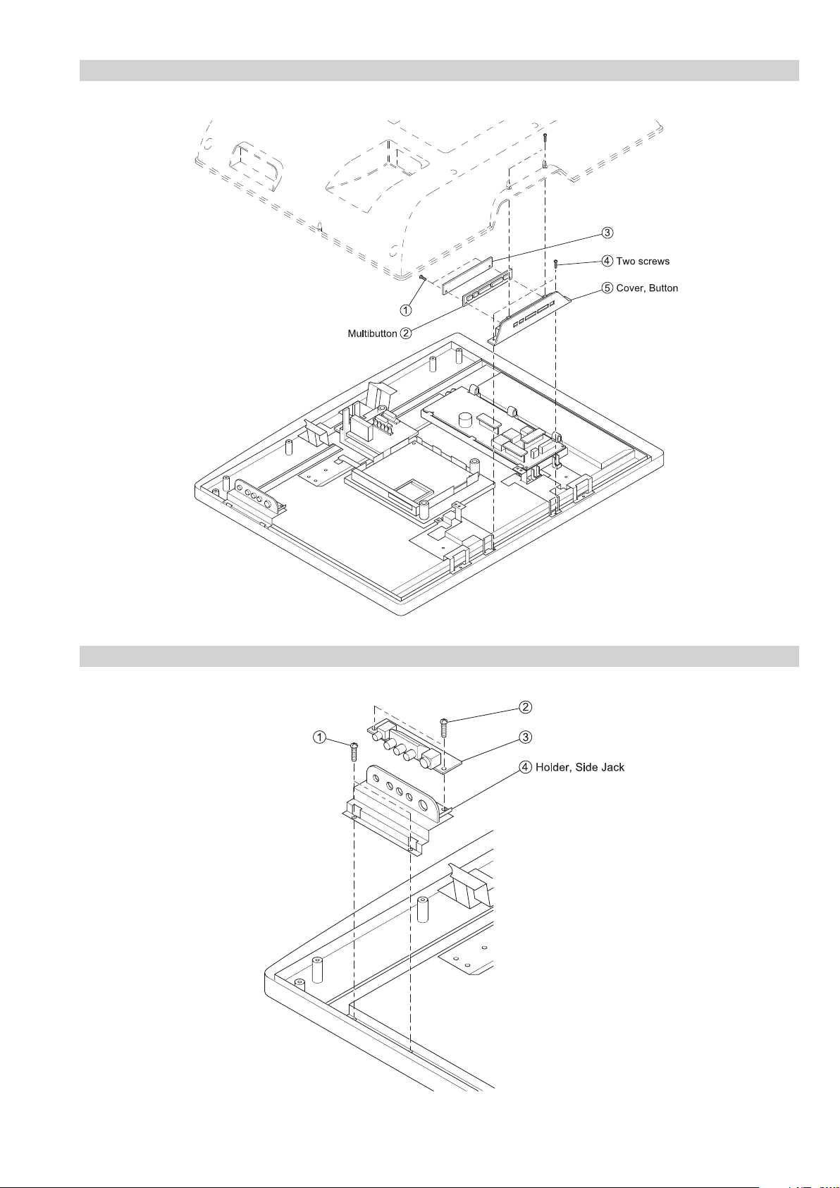
2-2. REAR COVER REMOVAL
Ten screws
One screw
Rear Cover
– 16 –
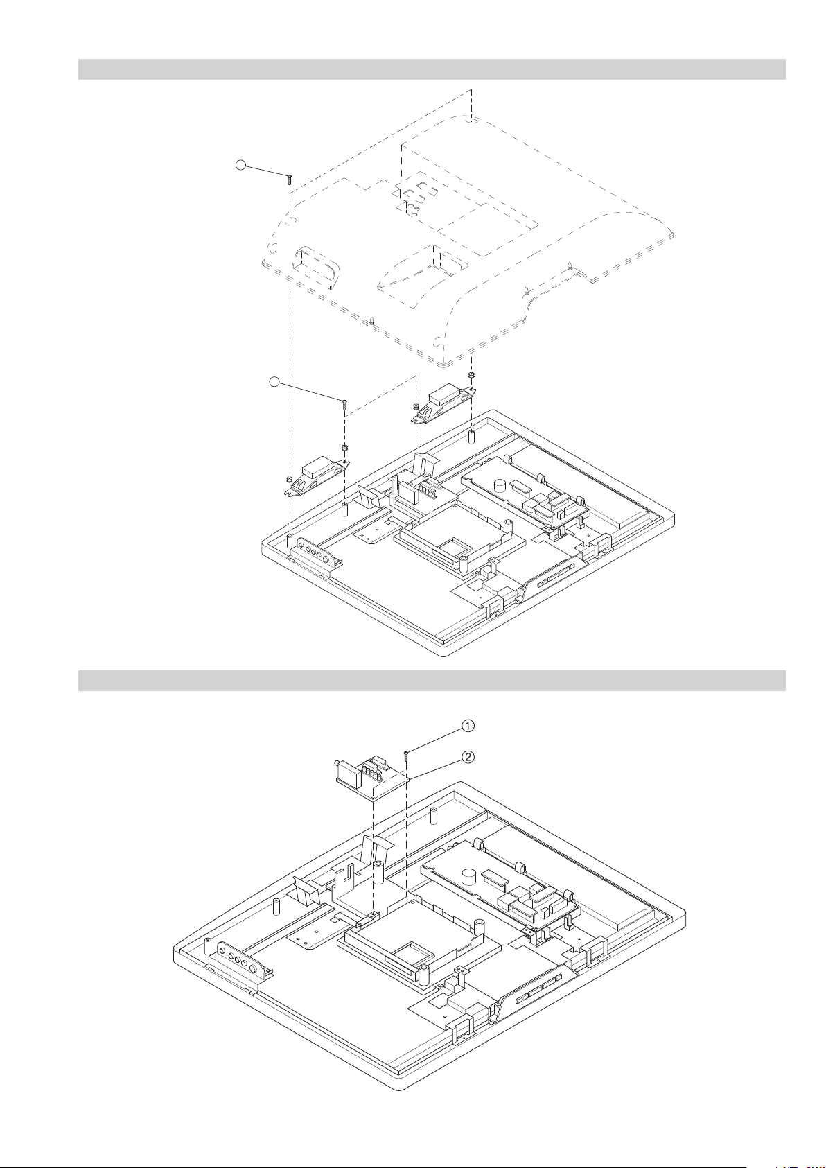
2-3. SPEAKER REMOVAL
SE-1
RM-ED007
Two screws
Two screws
1
2
2-4. A1/A1P BOARD REMOVAL
Two screws
A1/A1P Board
– 17 –
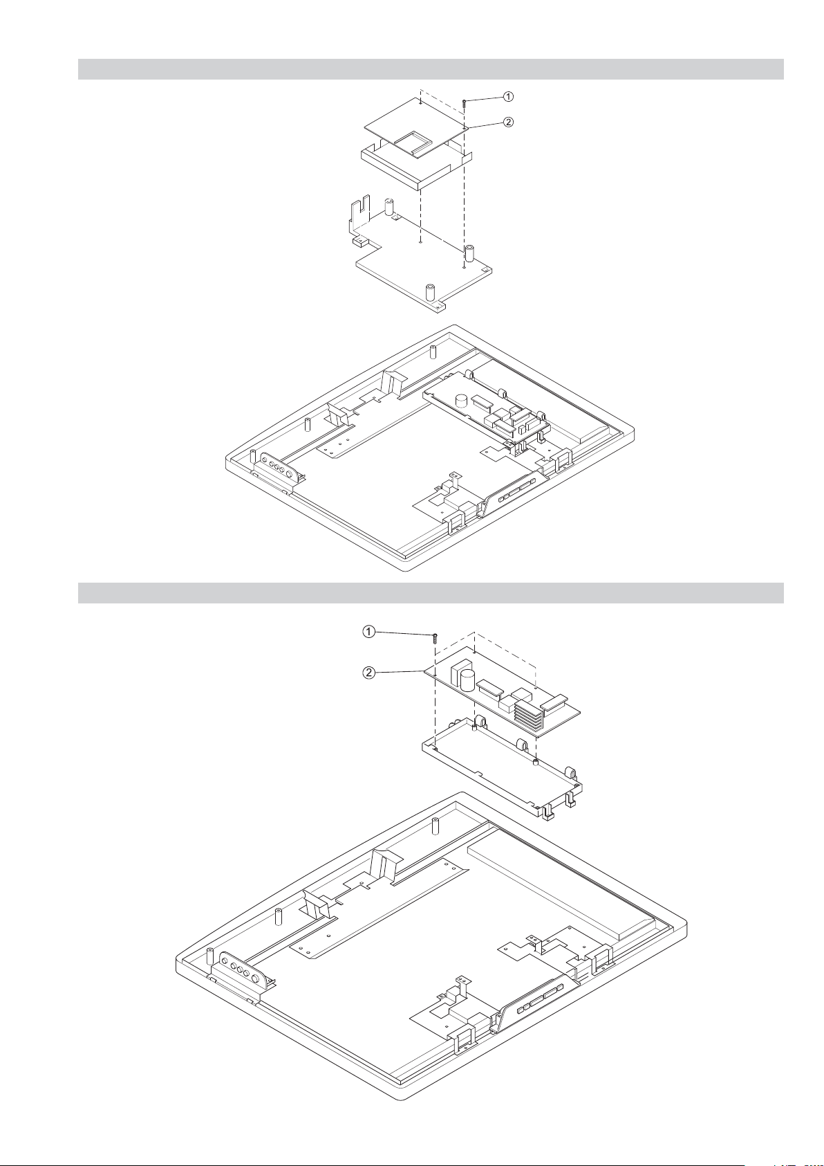
2-5. BDTR-2 BOARD REMOVAL
SE-1
RM-ED007
Two screws
BDTR-2 Board
2-6. G1 or G2 BOARD REMOVAL
Three screws
G1 Board (KDL-26/32P2520/30)
or
G2 Board (KDL-40P2530)
– 18 –
2-7. H1/H1P BOARD REMOVAL
SE-1
RM-ED007
H1/H1P Board
Two screws
2-8. H2/H2P BOARD REMOVAL
Two screws
Two screws
H2/H2P Board
– 19 –
2-9. H3/H3P BOARD REMOVAL
SE-1
RM-ED007
Two screws
H3/H3P Board
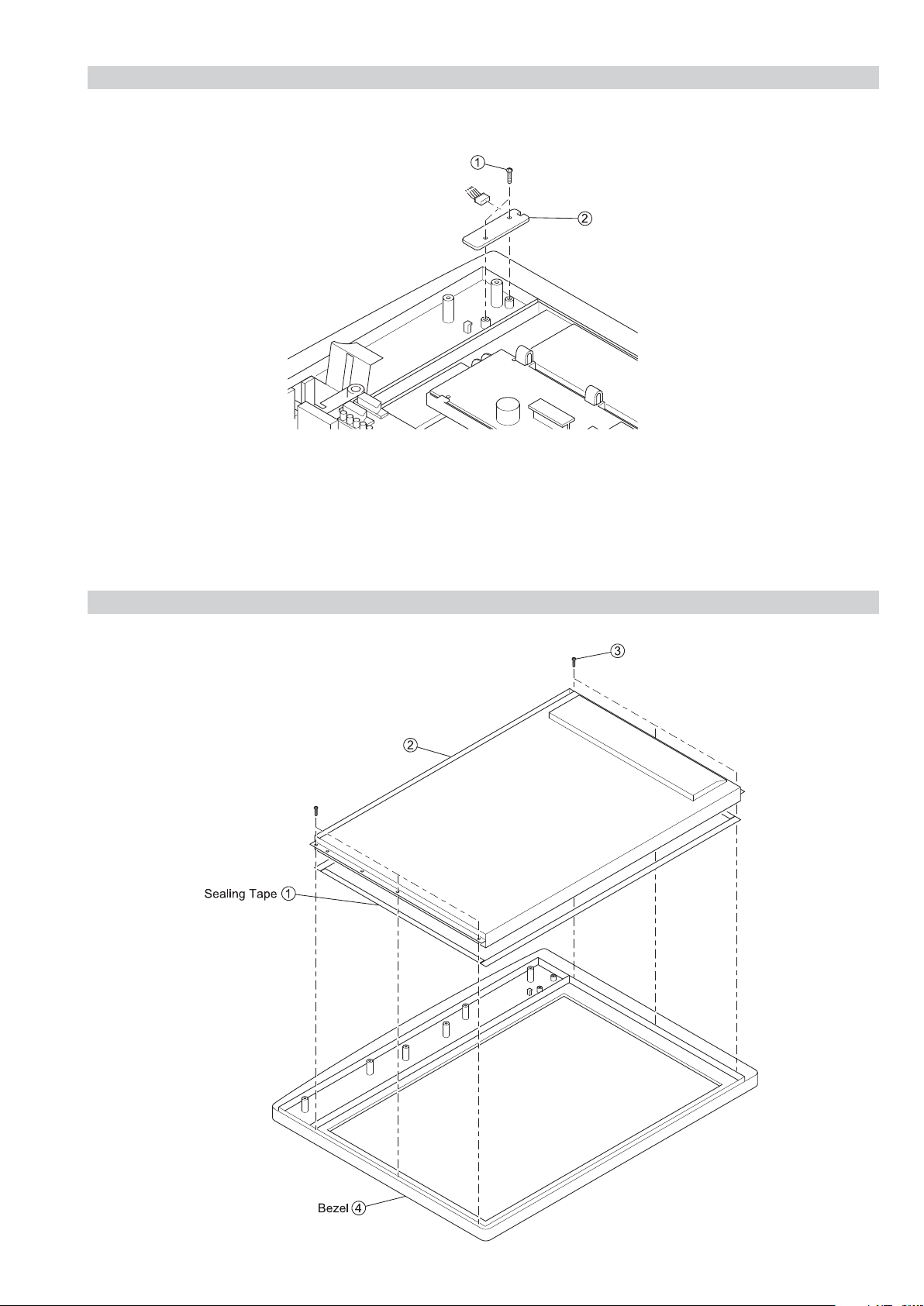
2-10. LCD PANEL REMOVAL
Six screws
LCD Panel
– 20 –
SECTION 3 CIRCUIT ADJUSTMENTS
3-1. Electrical Adjustments
Service adjustments to this model can be performed using the
supplied remote Commander RM-ED007.
How to enter into the Service Mode
1. Turn on the main power switch.
2. Press the following sequence of buttons on the Remote
Commander.
SE-1
RM-ED007
BACKLIGHT
i
+
(ON SCREEN
DISPLAY)
These 3 buttons must be pressed together
for approximately three seconds.
5
(DIGIT 5)
(PROG -)
{
‘TT—’ will appear in the upper right corner of the screen.
Other status information will also be displayed (See 3-3 Page
24).
3. Press ‘MENU’ on the remote commander to obtain the
following menu on the screen.
BACKLIGHT
HDMI
SOUND
IF ADJUST
ERROR MENU
SE1T v0.06 Nov06
FACTORY DATA: 11111111
SERIAL NUMBER: 4294967295
WORKING TIME: 0:22
4. Move to the corresponding adjustment item using the
up or down arrow buttons on the Remote Commander.
5. Press the right arrow button to enter into the required menu
item.
6. Press the ‘Menu’ button on the Remote Commander to quit
the Service Mode when all adjustments have been completed.
Note :
• After carrying out the service adjustments, to prevent the
customer accessing the ‘Service Menu’ switch the TV set
OFF and then ON.
BACKLIGHT
U BACKLIGHT
BL SETUDEN
BL BOTTOM
ECO MODE
APL MAX
DIMMER MIN
APL FACTOR
DIMMER
APL MIN
HDMI
VAI2
VAI3
Vper MSB
Vper ISB
Hper MSB
HS Width MSB
STM LSB
Ri (MSB)
Ri (LSB)
Aksv_0
Aksv_1
Aksv_2
Aksv_3
Aksv_4
An_0
An_1
An_2
An_3
An_4
An_5
An_6
An_7
Pj
Ainfo
Flags
(0, 255)
(0, 10)
(0, 255)
(0, 255)
(0, 1)
(0, 255)
(0, 255)
(0, 255)
(0, 255)
(0, 255)
(0, 255)
(0, 255)
(0, 255)
(0, 255)
(0, 255)
(0, 255)
(0, 255)
(0, 255)
(0, 255)
(0, 255)
(0, 255)
(0, 255)
(0, 255)
(0, 255)
(0, 255)
(0, 255)
(0, 255)
(0, 255)
(0, 255)
(0, 255)
(0, 255)
(0, 255)
(0, 255)
(0, 255)
(0, 255)
235
10
10
138
1
176
0
0
186
103
0
0
0
0
248
0
8
218
101
137
55
132
68
25
32
36
240
180
57
19
214
138
207
2
15
- 21 -

SE-1
RM-ED007
SOUND
M-N
M-D
M-S
S-M
D-M
N-M
Effect Mode
BBE Mode
BBE Vol main
BBE Vol res
B1
B2
B3
B4
B5
Loudness
MB_STR
MB_LIM
MB_HMC
MB_LP
MB_HP
SUBW_FREQ
NICAM C AD
NICAM Error
Stereo
Status 0000000110
(0, 511)
(-128, -1)
(+0, +127)
(+0, +127)
(-128, -1)
(0, 1023)
(+0, +2)
(-0, +127)
(+0, +255)
(+0, +7)
(-96, +96)
(-96, +96)
(-96, +96)
(-96, +96)
(-96, +96)
(+0, +68)
(+0, -127)
(-32, +0)
(+0, +127)
(+5, +30)
(+3, +30)
(+5, +40)
00000
(0, 2047)
(-128, +127)
192
-20
+20
+10
-10
496
+1
+0
+3
+0
+4
+0
-12
-12
+6
+23
+0
+0
+0
+5
+3
+5
2047
+0
ERROR MENU
E02: Reserved
E03: DC Fail
E04: PANEL DET
E05: NVM
E06: IIC
E07: HDMI
E08: DIGITAL
E09: TUNER
E10: SP
E11: VCTP
E12: PEXP
E13: RTC
WORKING TIME
HOURS
MINUTES
(0, 255)
(0, 255)
(0, 255)
(0, 255)
(0, 255)
(0, 255)
(0, 255)
(0, 255)
(0, 255)
(0, 255)
(0, 255)
(0, 255)
(0, 65535)
(0, 59)
0
0
0
0
0
0
0
0
0
0
0
0
0
38
IF ADJUST
Automute
Audio Gain
L Gating
Coincidence
AFT window
AFT Status
AGC TOP (-16, +15)
0
0
0
0
1
0111
-4
- 22 -
SE-1
RM-ED007
3-2. TEST MODE 2
Test Mode 2 is available by setting the TV for operation in Service Mode [ As shown on Page 21 ] , OSD ‘TT’ appears. The functions described below are available by selecting the two numbers. To release the ‘Test mode 2’, press 00, 10, 20 ... twice or switch the TV set into
Stand-by mode. In ‘TT Menu’ mode, it is possible to remove the Menu from the screen by pressing the Speaker Off button once. Pressing the
Speaker OFF button a second time will cause the Menu to reappear. The function is kept even when the menu is not displayed on screen !!.
'TT' mode off
00
Set volume to 35%
03
04 Set volume to 50%
Set volume to 65%
05
06 Set volume to 80%
Ageing mode (TV key swiyches off)
07
Shipping Condition
08
Picture level 50%
16
Factory toggle mode ("Fact" or "Norm")
19
UK Destination
24
All Europe Destinations
25
CBA mode toggle (On for factory mode)
27
ECS mode toggle
31
Set BCN channels preset
32
Clock display toggle
36
Hotel mode toggle
37
OTRUM mode
38
Digital test toggle
39
Re-initialise NVM
41
Dual Sound "A"
43
Dual Sound "B"
44
Dual Sound "Mono"
45
Dual Sound "Stereo"
46
Set NVM as non-virgin (CH59 only)
48
Set NVM as virgin (CH59 only)
49
Watchdog toggle
54
Tuner toggle
55
56 Reset all channels attenuation
Chip select toggle
58
Visual I2C toggle
59
Auto AGC
61
AM from baseband toggle
63
Set 40" for A3 or A4 panel
64
DDC toggle
65
HDMI EDID WP toggle
66
MSP Auto Carrier Mute function toggle
67
Set 26" settings AUO panel
68
Set 32" settings AUO panel
69
Set 20" settings Chi-Mei panel
71
Set 26" settings Samsung panel
72
Set 32" settings Samsung panel
73
Set 40" settings Samsung panel
74
Set centred balance
75
Set volume to maximum
76
Set volume to minimum
77
Set balance full left
78
Set balance full right
79
Digital BER display
81
Digital Service menu
82
Digital colour bar output from DENC
83
TS CI path through
84
Digital tuner power down (Only 1 power cycle,default
85
no power down)
Switch between two digital SW banks
86
Local keys test
87
Digital shipping conditions (Clear tune database)
88
LED test
89
- 23 -

3-3. TT OSD Labels
SE-1
RM-ED007
(1)
3 2AEP
(4)
ECS
(7)
DDC
(16)
CLK TW CV
Key:
1. Model configuration.
a. To set 26” AUO (TT68).
b. To set 26” Samsung (TT72).
c. To set 32” AUO (TT69).
d. To set 32” Samsung (TT73).
e. To set 20” Chi-Mei (TT71).
f. To set 40” Samsung (TT74).
2. Model destination.
3. Command prompt.
4. ECS enabled/disabled (TT31).
5. CBA is shown when the TV set is in CBA mode (This mode is available from Factory mode) (TT27).
6. Normal or Factory mode (TT19).
7. DDC enabled/disabled (TT65).
8. E is shown when EDID WP is enabled; - is shown otherwise (TT66).
9. O is shown when OTRUM is enabled; - is shown otherwise (TT38).
10. H is shown when Hotel mode is enabled; - is shown otherwise (TT37).
11. D is shown when Digital mode is enabled; A is shown when Analogue mode is enabled.
12. C (Default value) is shown when MSP Auto Carrier Mute function is enabled; - is shown otherwise (TT67).
13. M (Default value) is shown when AM sound is demodulated in MSP; A is shown when AFRIC demodulator is used (TT63).
14. S is shown when a SONY tuner is selected; P is shown when a PHILIPS tuner is selected (TT55).
15. C is shown when a Chi-Mei 20” panel is used; S is shown when a Samsung panel is used; A is shown when a AUO panel is used
(Changed by TT68 and TT69) for 26” and 32” respectively; 3 is shown when a 40” Samsung A3 panel is used; 4 is shown when a 40”
Samsung A4 panel is used (Changed by TT64).
16. Clk is shown when display clock is enabled; - is shown otherwise (TT36).
17. T is shown when digital test is enabled; - is shown otherwise (TT39).
18. W is shown when Watchdog is enabled; - is shown otherwise (TT54).
19. C is shown when chip select is enabled; - is shown instead (This mode is available from factory mode) (TT58).
20. V is shown when Visual I2C is enabled; - is shown otherwise (TT59).
(5)
CBA
(8)
E OHDCMSS
(17) (18) (19) (20)
(2) (3)
(9) (10) (11) (12) (13)(14)(15)
TT - -
(6)
No r m
- 24 -
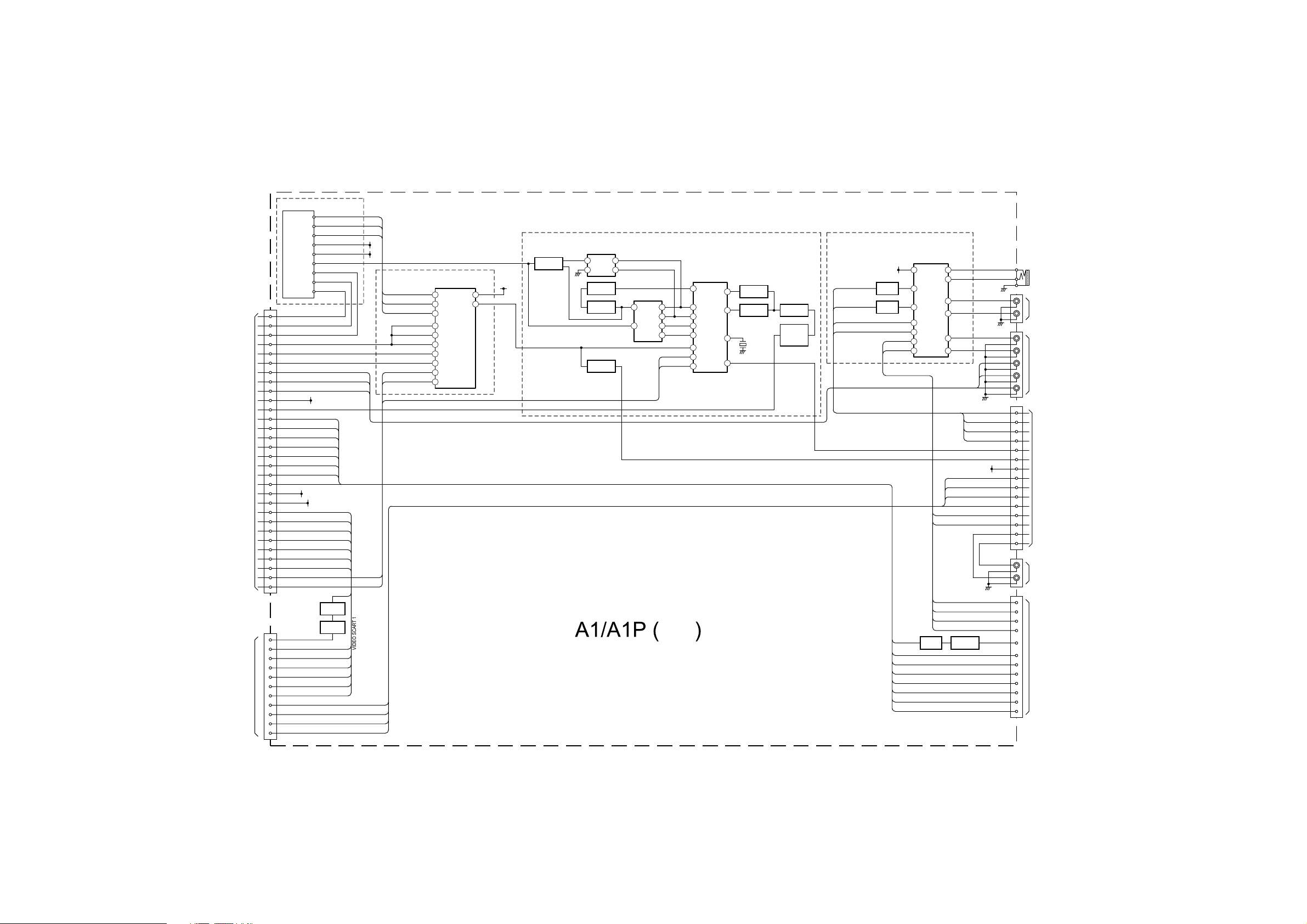
4-1. BLOCK DIAGRAMS (1)
TO BDTR-2 BOARD
CN3005
SCART 1
AV 1
CN2022
CN2021
DIGITAL IF 2
DIGITAL IF 1
17
IF DIGITAL -
18
IF DIGITAL +
12
AGC DIGITAL
7
TUNER 12C SW
10
12C SDA OFDM
9
12C SCL OFDM
V-YUV
22
U-YUV
24
Y-YUV
26
5V
2
CVBS TUNER
20
CVBS2 OUT
28
CVBS2 IN
30
MODE 2
31
AV LINK
32
FBLK 2
33
B2
34
G2
36
R2
38
8.5V
1
33V
4
CVBS1 OUT
40
CVBS1 IN
42
MODE 1
43
44 FBLK 1
45 B1
47 G1
49
R1
14
12C SCL
15
12C SDA
VIDEO OUT
19
BLUE IN
7
MODE 1
8
GREEN IN
11
RED IN
15
BLANKING
16
VIDEO IN
20
LEFT IN
6
RIGHT IN
2
LEFT OUT
3
RIGHT OUT
1
TU1300
TUNER
TU AGC
SDA
ANALOG IF
IF AGC
SCL
33V
5V
+5VA
V OUT 2 B
8.5V
33V
TUNER BLOCK
ANALOG AGC SW
12C SCL SW
12C SDA SW
33V
+5VA
IF ANALOG
IF AGC DIGITAL
IF DIGITAL +
IF DIGITAL -
V IN 2
MODE 2
AV LINK
BLK 2
BLUE 2
GREEN 2
RED 2
V OUT 1 B
V IN 1
MODE 1
BLK 1
BLUE 1
GREEN 1
RED 1
V OUT 1 B
Q2005
BUFFER
Q2004
AMP
BLUE 1
MODE 1
GREEN 1
RED 1
BLK 1
V IN 1
SC1 IN L
SC1 IN R
SC1 OUT L
SC1 OUT R
33V
5V
ANALOG AGC SW
12C SCL SW
12C SDA SW
TUNER 12C SW
TUNER 12C SW
TUNER 12C SW
12C SDA OFDM
12C SCL OFDM
SDA 5V
SCL 5V
TUNER SWITCH
IC1000
ANALOG MULTIPLEXER/
DEMULTIPLEXER
4
Z
VCC
15
Y
Z1
14
X
9
C
10
B
11
A
12
X0
2
Y0
13
X1
1
Y1
5V
16
ANALOG AGC
3
5V
STBY
D1200
RECTIFIER
SW1201
FILTER
SURFACE WAVE
L1
L2
Q1201
SWITCH
Q1202
SWITCH
Q1200
SWITCH
01
02
SW1200
SAW FILTER
1 4
10
5
6
7
SDA 5V
SCL 5V
TUNER, I/O
CONNECTIONS &
A/V SWITCHING
IC1200
IF-PLL
DEMODULATOR
22
OP/2
VIDEO
24
SIF
OP/1
23
SIF
1
VIF
2
VIF
VCD
14
TU AGC
10
SDA
QSS
11
SCL
Q1203
17
AMPLIFIER
Q1204
3
BUFFER
15
X1200
12
CVBS ANALOG RF
VIDEO SCART 2
AV SCART 1
ANALOG IF BLOCK
Q1205
AMPLIFIER
C1226
L1201
TUNED
CIRCUIT
AUDIO SWITCH
AUX-MUX-CTRL-B
AUX-MUX-CTRL-A
8.5V
Q2000
SWITCH
Q2001
SWITCH
AUX-MUX-OUT-R
AUX-MUX-OUT-L
SC2-IN-L
SC2-IN-R
AV SCART 2
V OUT 2 B
IC2000
4 CHANNEL
ANALOG
MULTIPLEXER/
DEMULTIPLEXER
16
VDD
9
B
10
A
13
X
3
Y
1
Y0
12
X0
SC2 OUT R
SC2 IN R
SC2 OUT L
SC2 IN L
Q2003
BUFFER
11
X3
4
Y3
2
Y2
15
X2
5
Y1
14
X1
SC1 IN L
SC1 IN R
SC1 OUT L
SC1 OUT R
SC2 OUT L
SC2 OUT R
DV1 L
DV1 R
L-YUV
R-YUV
Q2002
AMPLIFIER
L-YUV
R-YUV
U-YUV
V-YUV
Y-YUV
AUX-MUX-OUT-R
AUX-MUX-OUT-L
AUX-MUX-CTRL-B
AUX-MUX-CTRL-A
QSS
AGC DEFEAT
5V STBY
L1 IN
R1 IN
L1 OUT
R1 OUT
L2 OUT
R2 OUT
LINEOUT R
LINEOUT L
OUT L
OUT R
RIGHT OUT
RIGHT IN
LEFT OUT
LEFT IN
VIDEO OUT
AV LINK
BLUE 2
MODE 2
GREEN 2
RED 2
BLK 2
V IN 2
PC-R
PC-L
J2023
J2022
L
R
J2024
CN2024
4
5
6
7
8
1
2
16
17
19
20
13
14
10
11
J2021
L
R
CN2023
1
2
3
6
19
10
7
8
11
15
16
20
PC
CONNECTION
DVI
CONNECTOR
EXTERNAL
CONNECTOR
TO BDTR-2 BOARD
CN3006
AUDIO OUT
SCART 2
AV 2
- 25 -
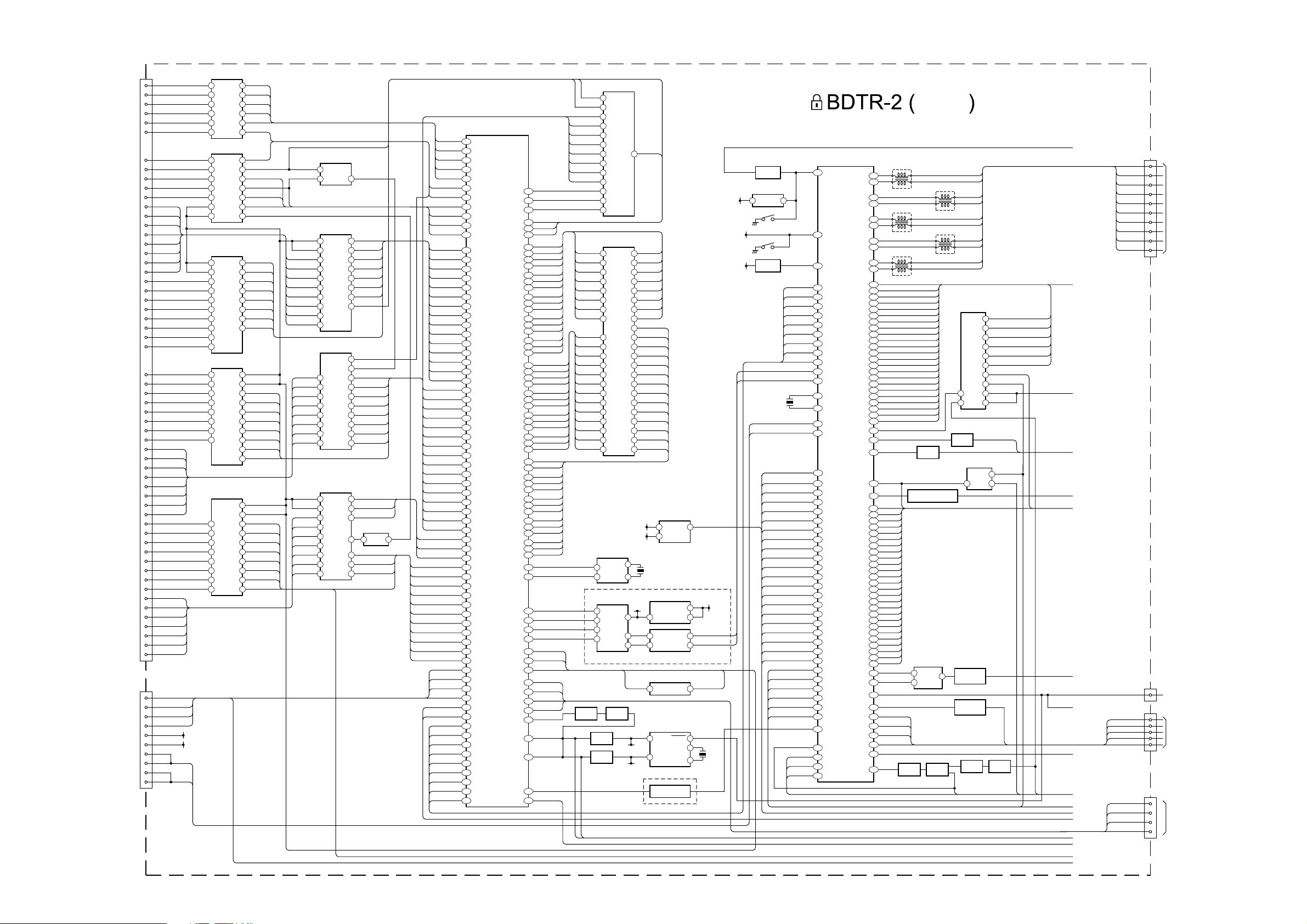
4-1. BLOCK DIAGRAMS (2)
CN5750
B26
INPACK
A16
IREQ
B2
CD1
B33
CD2
B9
VS1
B25
WAIT
A7
CE1
A15
WE
B10
IORD
B24
RESET
B27
REG
A12
CA(8)
A11
CA(9)
A8
CA(10)
A10
CA(11)
A21
CA(12)
A13
CA(13)
A14
CA(14)
A9
CARD OEB
A29
CA(0)
A28
CA(1)
A27
CA(2)
A26
CA(3)
A25
CA(4)
A24
CA(5)
A23
CA(6)
A22
CA(7)
PCMCIA
CARD
B7
MODE (7)
B6
MODE (6)
B5
MODE (5)
B4
MODE (4)
B3
MODE (3)
B32
MODE (2)
B31
MODE (1)
B30
A30
D0
CD(0)
A31
D1
CD(1)
A32
D2
CD(2)
A2
D3
CD(3)
A3
D4
CD(4)
A4
D5
CD(5)
A5
D6
CD(6)
A6
D7
CD(7)
B22
MD1 7/A25
B21
MD1 6/A24
B20
MD1 5/A23
B19
MD1 4/A22
B16
MD1 3/A21
B15
MD1 2/A20
B14
MD1 1/A19
B13
MD1 0/A18
B29
MOSTRT
B28
MOVAL
B23
MOCLK
A20
MICLK
A19
MIVAL
B12
MISTRT
B11
IOWR
CN3008
12
RXD1B
7
TXD1B
8
JTAG RESET
10
JIG MODE
6
SERVICE
CONNECTOR
SDA 5V
15
SCL 5V
3
RXD
16
RXD
2
TXD
17
TXD
OCTAL BUFFER/LINE DRIVER
INPACK
4
nIREQ
5
nCD1
6
nCD2
7
VS1
8
nWAIT
9
OCTAL BUFFER/LINE DRIVER
nCE1
18
nCARD-WE
17
nIORD
nREG
nCL-EN
nCL-EN
15
13
12
19 14
PCCARD-RST
OCTAL BUFFER/LINE DRIVER
1
nCL-EN
19
CA(0)
18
CA(1)
17
CA(2)
16
CA(3)
CA(4)
14 8
CA(5)
13
CA(6)
12
CA(7)
11
OCTAL BUFFER/LINE DRIVER
2
MODE (6)
3
MODE (5)
4
MODE (4)
5
MODE (3)
6
MODE (2)
7 15
MODE (1)
MODE (0)MODE (0)
9
OCTAL BUFFER/LINE DRIVER
MD1(7)
18
MD1(6)
17
MD1(5)
16
MD1(4)
15
MD1(3)
14
MD1(2)
13
MD1(1)
12
MD1(0)
11
SDA
SCL
IC5751
A2
A3
A4
A5
A6
A7
IC5750
Y0
Y1
Y3
Y5
Y6
IOE1
IOE2 Y4
IC5753
IOE1
IOE2
Y0
Y1
Y2
Y3
Y4 A6
Y5
Y6
Y7
IC5756
IOE1A0
A1
IOE2
A2
A3
A4
A5
A6
A7
IC5757
IOE2
IOE1
Y0
Y1
Y2
Y3
Y4
Y5
Y6
Y7
Y2
Y3
Y4
Y5
Y6
Y7
A0
A1
A3
A4
A5
A6
A0
A1
A2
A3
A4
A5
A7
Y0
Y1
Y2
Y3
Y4
Y5
Y6
Y7
A0
A1
A2
A3
A4
A5
A6
A7
INPACKB
16
IREQB
15
CD1B
14
CD2B
13
VS1B
12
nCL-WAIT
11
CE1B
2
FWEB
3
IORDB
5
IOWRB
6
CARD RESET
7
REGB
81
nIOWR
RADD(0)nCL-EN
2
RADD(1)
3
RADD(2)
4
RADD(3)
5
RADD(4)
6
RADD(5)
715
RADD(6)
RADD(7)
9
nCL-ENMODE (7)
1
nCL-EN
19
RDATA(15)
18
RDATA(14)
17
RDATA(13)
16
RDATA(12)
RDATA(11)
148
RDATA(10)
13
RDATA(9)
12
RDATA(8)
11
nCL-EN
19
nCL-EN
1
IN-TSD(7)
2
IN-TSD(6)
3
IN-TSD(5)
4
IN-TSD(4)
5
IN-TSD(3)
6
IN-TSD(2)
7
IN-TSD(1)
8
IN-TSD(0)
9
JTAG RESET
IC5752
2 I/P NAND
FWEB
1
B
A
IC5755
IC5759
IOE1
B0 A0
B1
B2
B3
B4
B5
B6
B7
IC5758
A2
A3
A4
Y0
Y5
Y6
Y7
DIR
4
Y
RADD(8)
2
A0
RADD(9)
3
A1
RADD(10)
4
A2
RADD(11)
5
A3
RADD(12)
6
A4
RADD(13)
715
A5
RADD(14)
A6
FOEB
9
A7
CEIB
19
DIR
1
DIR
RDATA(0)
2
RDATA(1)
3
A1
RDATA(2)
4
A2
RDATA(3)
5
A3
RDATA(4)
6
A4
RDATA(5)
7
A5
RDATA(6)
8
A6
RDATA(7)
9
A7
16
15
BUF-MDO-EN
14
Y4
INVERTING BUFFER
2
A0
IN-TSBCLK
7
A5
IN-TSBSYNC
8
A6
IN-TSPVAL
9
A7
IC5754
5Y 6A
IOWRB
2
OCTAL BUFFER/LINE DRIVER
nCL-EN
1
IOE1
nCL-EN
19
IOE2
CA(8)
18
Y0
CA(9)
17
Y1
CA(10)
16
Y2
CA(11)
Y3
CA(12)
14 8
Y4
CA(13)
13
Y5
CA(14)
12
Y6
CAD OEB
11
Y7
OCTAL TRANSCEIVER
CD(0)
18
CD(1)
17
CD(2)
16
CD(3)
15
CD(4)
14
CD(5)
13
CD(6)
12
CD(7)
11
OCTAL BUS BUFFER
nCL-EN BUF-MDO-CLK
19
IOE2
nCL-EN BUF-MDO-STRT
1
IOE1Y2Y3
MOCLK
4
MOSTRT
5
MOVAL
6
IOWR
18
MICLK
13
MISTRT
12
MIVAL
11
IC5680
NAND FLASH MEMORY
FWEB
18
FOEB
8
RDATA(0)
29
RDATA(1)
IC5630
IREQB
CD1B
CD2B
VS1B
CEIB
IORDB
REG B
TXDIB
RXDIB
G2
K3
V1
C1
P2
F3
P4
P2
G1
F4
N4
D3
E1
E3
F1
H2
J2
G4
H4
L3
M3
T2
N3
K1
N1
M1
E2
D4
C2
V4
W2
V2
R4
U4
C3
D2
D1
U1
T3
T1
R3
R1
H1
E4
F2
A4
B4
C4
A3
B2
A2
B2
A1
D5
B5
A5
AA5
AA6
AA10
AA16
Y7
AA7
AA20
AA21
Y20
Y21
W20
W21
V20
V21
V19
MPEG DECODER
W1
U3
U4
K2
L1
P1
C16
D16
C15
D15
C14
D14
C13
D13
B13
A13
B14
A14
B15
A15
B16
A16
C7
D7
C6
D6
B6
A6
B7
A7
B8
A8
D8
B9
A9
C8
D9
A11
A12
C12
C9
D10
C10
D11
B10
A10
B11
B12
C11
V7
M21
W6
Y5
AA4
W5
C21
A20
B20
W3
Y3
AA2
V16
V9
Y8
AA8
Y12
AA15
NAND RBB
NAND CLE
NAND ALE
FCSBO
FWEB
FOEB
DQ(0)
DQ(1)
DQ(2)
DQ(3)
DQ(4)
DQ(5)
DQ(6)
DQ(7)
DQ(8)
DQ(9)
DQ(10)
DQ(11)
DQ(12)
DQ(13)
DQ(14)
DQ(15)
DADD(0)
DADD(1)
DADD(2)
DADD(3)
DADD(4)
DADD(5)
DADD(6)
DADD(7)
DADD(8)
DADD(9)
DADD(10)
DADD(11)
DADD(12)
DBA1
DBA0
DQM1
DQS1
DQS0
DCSB
DRASB
DCASB
DWEB
DCKE
DCLK DDR
DCLK B
DV REF
DQM0
PWM OUT
CLK 27M
ADO
ALRCK
ABCK
AMCK
nSMC INT
CI PWR EN
nCI EN
PMSDIO
PMSBS
PMSSCLK
PMSINS
RESET N
SDA EMMA
SCL EMMA
CVBS
nFE-RESET
INPACKB
nCI-WAIT
CARD RESET
IOWRB
RADD(0)
RADD(1)
RADD(2)
RADD(3)
RADD(4)
RADD(5)
RADD(6)
RADD(7)
RADD(8)
RADD(9)
RADD(10)
RADD(11)
RADD(12)
RADD(13)
RADD(14)
RDATA(0)
RDATA(1)
RDATA(2)
RDATA(3)
RDATA(4)
RDATA(5)
RDATA(6)
RDATA(7)
RDATA(8)
RDATA(9)
RDATA(10)
RDATA(11)
RDATA(12)
RDATA(13)
RDATA(14)
RDATA(15)
nIOWR
1310
BUF-MDO-CLK
BUF-MDO-STRT
BUF-MDO-EN
IN TSD(0)
IN TSD(1)
IN TSD(2)
IN TSD(3)
IN TSD(4)
IN TSD(5)
IN TSD(6)
IN TSD(7)
IN-TSBCLK
IN-TSBSYNC
IN-TSPVAL
JTAG RESET
JIG MODE
SDA COFDM
SCL COFDM
VDO(0)
VDO(1)
VDO(2)
VDO(3)
VDO(4)
VDO(5)
VDO(6)
VDO(7)
VDO CLK
RDATA(2)
RDATA(3)
RDATA(4)
RDATA(5)
RDATA(6)
RDATA(7)
DQ(0)
DQ(1)
DQ(2)
DQ(3)
DQ(4)
DQ(5)
DQ(6)
DQ(7)
DADD(0)
DADD(1)
DADD(2)
DADD(3)
DADD(4)
DADD(5)
DADD(6)
DADD(7)
DADD(8)
DADD(9)
DADD(10)
DADD(11)
DADD(12)
3
5
1
3
2
4
AUDIO DAC & AMP
Q5923
SWITCH
Q5920
BUFFER
Q5921
BUFFER
30
31
32
41 9
42
43
44
7
16
17
IC5681
DDR SDRAM
2
4
5
7
8
10
11
13
29
30
31
32
35
36
37
38
39
40
28
41
42
IC5682
27 MHZ CLOCK
X1
VIN
CLK
X2
IC5782
STEREO DAC
DATA
VDD
RO
LO
Q5922
BUFFER
SDA
SCL
FCSBO
DQ(8)
54
DQ(9)
56
DQ(10)
57
DQ(11)
59
DQ(12)
60
DQ(13)
62
DQ(14)
63
DQ(15)
65
DCLK DDR
45
DCLK B
46
DV REF
49
DBA1
27
DBA0
26
DQM1
47
DQM0
20
DQS1
51
DQS0
16
DCSB
24
DRASB
23
DCASB
22
DWEB
21
DCKE
44
SCL
SDA
1
8
5V
AUDIO
7 4
5
8
nC1 EN
SDA
SCL
IC3004
SERIAL EEPROM
6
5
X5680
IC5781
DROPOUT REGULATOR
CONTROL
NOISE
OUT
2
A-IN
A-OUT
6
B-IN
B-OUT
IC5783 OP AMP
IC5786
USB POWER SWITCH
2 1
IC5780
REAL TIME CLOCK
3
SDA
INTRC
OSC IN
SCL
2
OSC OUT
VIDEO AMP BUFFER
Q5780
BUFFER AMP
NVM-WP
7
1
5
DIGITAL RF R
1
DIGITAL RF L
7
CI PWR EN
KEY
4
9
8
8.5V
X5780
3.3V
SCL
SDA
Q3001
RESET
IC3005
SYSTEM RESET
2 4
SW3001
SW3000
Q3017
X3000
AUX-MUX OUT R
AUX-MUX OUT L
PDHDMI/MAIN ON
TUNER 12C SWITCH
AUDIODATA-HDMI
AUDIOCLK-HDMI
RESETDB RESET
VDO(0)
VDO(1)
VDO(2)
VDO(3)
VDO(4)
VDO(5)
VDO(6)
VDO(7)
VDO(CLK)
DIGITAL RF R
DIGITAL RF L
OUT
RXD
TXD
HOT_PLUG2
HOT_PLUG1
NVM WP
MODE 1
MODE 2
LINE R
LINE L
MONITOR R
MONITOR L
SELECT OUT R
SELECT OUT L
TCK
TDO
TMS
POWER LCD
POWER DET
EDID WP
AUDIOWS-HDMI
PC-HDMI
INT-HDMI
RF-DIGITAL
POWER ON/
POWER ON LED
PC BLUE
PC GREEN
PC RED
IC3006
VIDEO CONTROLLER/TELETEXT
8
83
84
198
199
200
201
202
203
204
205
206
11
12
79
IN
78
106
105
120
119
116
87
88
27
28
25
26
21
22
15
16
208
1
4
5
TDI
6
7
166
167
110
40
38
39
161
160
190
2
172
173
174
L3000 FILTER
141
140
41
138
137
L3002 FILTER
135
134
41
132
131
L3004 FILTER
129
128
41
FB-SCART 1
175
BLUE SCART 1/Y FRONT
176
GREEN SCART 1/C FRONT
177
RED SCART 1
178
PB-HD
179
Y-HD
180
PR-HD
181
BLUE SCART 2
182
FB-SCART 2
183
GREEN SCART 2
184
RED 2/C-DIG
187
CVBS 2/Y-DIG
188
CVBS SCART 1
189
RF ANALOGUE
191
CVBS SELECT
194
CVBS-LAST-RF
195
SCART 1-L
10
SCART 1-R
9
FRONT-L
14
FRONT-R
13
ANALOG RF R
23
ANALOG RF L
24
HP DET
109
DVS
47
102
101
HDMI-H
171
31
DB0
73
DB1
72
DB2
71
DB3
70
DB4
69
DB5
68
DB6
67
DB7
66
DG0
65
DG1
64
DG2
63
DG3
62
DG4
61
DG5
60
DG6
59
DG7
58
DR0
57
DR1
56
DR2
55
DR3
54
DR4
53
DR5
52
DR6
51
DR7
50
DCLK
49
DE
48
AV LINK 1
92
AV LINK 2
91
KEY
162
SIRCS
3
GREEN LED
165
REC LED
168
STBY LED
90
TIMER LED
89
AC ON/OFF
159
PC-DET
118
MAIN MICRO
CONTROLLER, PANEL
DRIVING, AUDIO & VIDEO
PROCESSOR
23
TATA+
L3001 FILTER
41
23
TCTC+
L3003 FILTER
41
23
TDTD+
Q3003
SWITCH
Q3350, Q3351
BUFFER & AMPLIFIER
IC3001
COMPARATOR
5
1
Q3123
Q3121
BUFFER
SWITCH
DEMULTIPLEXER
PC-V
SWITCH
3
(Sht 1 of 2)
23
TBTB+
23
TCLKTCLK+
IC3002
ANALOG
MULTIPLEXER/
5
4
3
2
1
15
12
11
1014
9
13
LOUDSPEAKER
Q3002
LINE OUT MUTE
IC3000
BILATERAL SWITCH
1 2
Q3000
HIGH SPEED
SWITCH
Q3004
HIGH SPEED
SWITCH
Q3122
BUFFER
BLUE SCART
GREEN SCART 1/C FRONT
GREEN SCART1
Y FRONT
C FRONT
BLUE SCART 1/Y FRONT
HDMI-V
PC/HDMI
SCI/FRONT
MUTE
PC/HDMI
4
PCH
AV LINK
SIRCS
PC-V
Q3120
SWITCH
QSS
KEY
PORT CS
SHEET 2 A
SHEET 2 B
SHEET 2 C
SHEET 2 D
SHEET 2 E
SHEET 2 F
SHEET 2 G
SHEET 2 H
SHEET 2 J
SHEET 2 K
SHEET 2 L
SHEET 2 M
SHEET 2 N
SHEET 2 P
SHEET 2 R
SHEET 2 S
SHEET 2 T
TCLK-
TCLK+
STBY LED
ON-TIMER
GREEN LED
REC LED
SIRCS
PMSBS
PMSDIO
PMSINS
PMSSCLK
TA+
TB+
TC+
TD+
KEY
CN3001
1
TA-
3
5
TB-
7
19
9
TC-
TD-
11
19
13
15
17
19
CN3002
1
CN3003
4
5
6
7
10
CN5883
2
4
6
8
TO LCD
PANEL
TO H1/H1P
BOARD
CN9000
TO H3/H3P
BOARD
CN9300
MEMORY STICK
- 26 -
 Loading...