

Page 1

3-876-517-11(1)
LCD Digital Color TV
KDL-26NL140
KDL-32NL140
KDL-37NL140
© 2008 Sony Corporation
Operating Instructions
Page 2
Owner’s Record
The model and serial numbers are located at
the rear of the TV. Record these numbers in
the spaces provided below. Refer to them
whenever you call upon your Sony dealer
regarding this TV.
Model Name
Serial No.
WARNING
To reduce the risk of fire or electric shock, do
not expose this apparatus to rain or moisture.
CAUTION
To prevent electric shock, do not use this
polarized AC plug with an extension cord,
receptacle or other outlet unless the blades can
be fully inserted to prevent blade exposure.
Declaration of Conformity
Trade Name: SONY
Model: KDL-26NL140/KDL-32NL140/
KDL-37NL140
Responsible Party: Sony Electronics Inc.
Address: 16530 Via Esprillo
San Diego, CA 92127 U.S.A.
Telephone Number: 858-942-2230
This device complies with part 15 of the FCC
rules. Operation is subject to the following two
conditions : (1) This device may not cause
harmful interference, and (2) this device must
accept any interference received, including
interference that may cause undesired operation.
NOTIFICATION
This equipment has been tested and found to
comply with the limits for a Class B digital
device, pursuant to Part 15 of the FCC Rules.
These limits are designed to provide reasonable
protection against harmful interference in a
residential installation. This equipment generates,
uses and can radiate radio frequency energy and,
if not installed and used in accordance with the
instructions, may cause harmful interference to
radio communications. However, there is no
guarantee that interference will not occur in a
particular installation. If this equipment does
cause harmful interference to radio or television
reception, which can be determined by tu rning the
equipment off and on, the user is encouraged to
try to correct the interference by one or more of
the following measures:
s
Reorient or relocate the receiving antenna.
s Increase the separation between the
equipment and receiver.
s Connect the equipment into an outlet on a
circuit different from that to which the
receiver is connected.
s Consult the dealer or an experienced
radio/TV technician for help.
Pursuant to FCC regulations, you are
cautioned that any changes or modifications
not expressly approved in this manual could
void your authority to operate this equipment.
Safety
s Operate the TV only on 120 V AC.
s
Use the AC power cord specified by Sony
and suitable for the volt age where you use it.
s The plug is designed, for safety purposes,
to fit into the wall outlet only one way. If
you are unable to insert the plug fully into
the outlet, contact your dealer.
s If any liquid or solid object should fall
inside the cabinet, unplug the TV
immediately and have it checked by
qualified service personnel before
operating it further.
s If you will not be using the TV for several
days, disconnect the power by pulling the
plug itself. Never pull on the cord.
s When disconnecting AC power cord, the
power cord should be easily accessible for
disconnection.
s The apparatus must not be exposed to
dripping or splashing. Do not place
objects filled with liquids, such as vases
on the apparatus.
s For details concerning safety precautions,
see “Safety and Regulatory Booklet”
(included).
Installing
s The TV should be installed near an easily
accessible power outlet.
s To prevent internal heat buildup, do not
block the ventilation openings.
s Do not install the TV in a hot or humid
place, or in a place subject to excessive
dust or mechanical vibration.
s Avoid operating the TV at temperatures
below 41°F (5°C).
s If the TV is transported directly from a
cold to a warm location, or if the room
temperature changes suddenly, the picture
may be blurred or show poor color due to
moisture condensation. In this case,
please wait a few hours to let the moisture
evaporate before turning on the TV.
s To obtain the best picture, do not expose
the screen to direct illumination or direct
sunlight. It is recommended to use spot
lighting directed down from the ceiling or
to cover the windows that face the screen
with opaque drapery. It is desirable to
install the TV in a room where the floor
and walls are not of a reflective material.
CAUTION
Use your TV with the following
WALL-MOUNT BRACKET.
Sony TV Model No.
KDL-26NL140 KDL-32NL140
Sony Wall-Mount
Bracket Model No.
Use with other WALL-MOUNT BRACKET
may cause instability and possibly result in
injury (see page 8).
SU-WL100 SU-WL500
To Customers
Sufficient expertise is required for installing the
specified TV. Be sure to subcontract the
installation to Sony dealer or licensed
contractors and pay adequate attention to safety
during the installation.
KDL-37NL140
Note
This television includes a QAM demodulator
which should allow you to receive unscrambled
digital cable television programming via
subscription service to a cable service provider.
Availability of digital cable television
programming in your area depends on the type
of programming and signal provided by your
cable service provider.
For Customers in Canada
This Class B digital apparatus complies with
Canadian ICES-003.
For Customers in the United
States
Lamp in this product contains
mercury. Disposal of these
materials may be regulated due to
environmental considerations.
For disposal or recycling
information, please contact your
local authorities or the Electronic
Industries Alliance
(www.eiae.org).
Trademark Information
Macintosh is a trademark licensed to Apple,
Inc., registered in the U.S.A. and other countries.
Manufactured under license from Dolby
Laboratories. “Dolby” and the double-D symbol
are trademarks of Dolby Laboratories.
HDMI, the HDMI logo and High-Definition
Multimedia Interface are trademarks or
registered trademarks of HDMI Licensing, LLC.
TruSurround XT, SRS and ( ) symbol are
trademarks of SRS Labs, Inc. TruSurround XT
technology is incorporated under license from
SRS Labs, Inc.
Fergason Patent Properties, LLC:
U.S. Patent No. 5, 717, 422
U.S. Patent No. 6, 816, 141
Blu-ray is a trademark.
“BRAVIA” and , , BRAVIA
Theatre Sync and DMPORT are trademarks or
registered marks of Sony Corporation.
“PLAYSTATION” is a registered trademark
and “PS3” is a trademark of Sony Computer
Entertainment Inc.
2
Page 3
Contents
Welcome to the World of BRAVIA®
The Four Steps to Stunning HD Experience:
Set, Sound, Source, and Setup................4
Picture Quality and Aspect Ratio ..................4
Getting Started
1. Installing the TV ......................................... 5
How to Carry the TV ....................................5
How to Attach the Table-Top Stand ............5
Securing the TV ...........................................6
Bundling the Connecting Cables .................7
Preparation for Wall-Mounting .....................8
Installing the Wall-Mount Bracket ................9
When Installing the TV Against a Wall or
Enclosed Area ....................................11
2. Locating Inputs and Outputs ..................12
Side Panel .................................................12
Rear Panel .................................................13
3. Connecting the TV ...................................15
Cable System and/or VHF/UHF ................15
HD Cable Box/HD Satellite Box .................15
PC ..............................................................17
Other Equipment .......................................18
4. Setting Up the Channel List -
Initial Setup ............................................. 19
Exploring Fun Features
Using BRAVIA Theatre Sync™ with
Control for HDMI ..................................... 20
Using DIGITAL MEDIA PORT adapter ........ 20
Remote Control
and TV Controls/Indicators
Inserting Batteries ........................................21
When Using the Remote Control.................21
Remote Control.............................................22
TV Controls/Indicators .................................26
Using TV Menus
Navigating through TV Menus.....................27
Menu Descriptions........................................27
Using the Shortcuts Menu .....................28
Using the Picture Menu ........................30
Using the Sound Menu .........................31
Using the Screen Menu.........................32
Using the Channel Menu.......................33
Using the Parental Lock ........................34
Using the Setup Menu...........................37
Other Information
Troubleshooting............................................39
Specifications................................................42
Index...............................................................43
Quick Setup Guide (separate volume)
Provides a variety of optional equipment
connection diagrams.
Customer Support
http://www.sony.com/tvsupport
On-line Registration
United States
http://productregistration.sony.com
Canada
http://www.sonystyle.ca/registration
3
Page 4
Welcome to the World of BRAVIA
y
Thank you for purchasing this Sony BRAVIA® high-definition television. The quality of the image you see on
your BRAVIA TV is only as good as the quality of the signal it receives. To experience the stunning detail of
your new BRAVIA TV, you need access to HD programming. Your BRAVIA TV can receive and display HD
programming from:
• Over-the-air broadcasting via HD-quality antenna
• HD cable subscription
• HD satellite subscription
• Blu-ray Disc™ player or other external equipment
Contact your cable or satellite provider for information on upgrading to HD programming.
®
To learn more about HDTV, visit:
U.S.A http://www.sony.com/HDTV
Canada http://www.sonystyle.ca/hd
The Four Steps to Stunning HD Experience: Set, Sound, Source, and Setup
Along with your BRAVIA TV set, a complete HD system requires an HD sound system, a source of HD
programming and proper setup connections. This manual explains basic setup connections (see page 15).
The Quick Setup Guide, enclosed separately, illustrates how to connect other optional equipment.
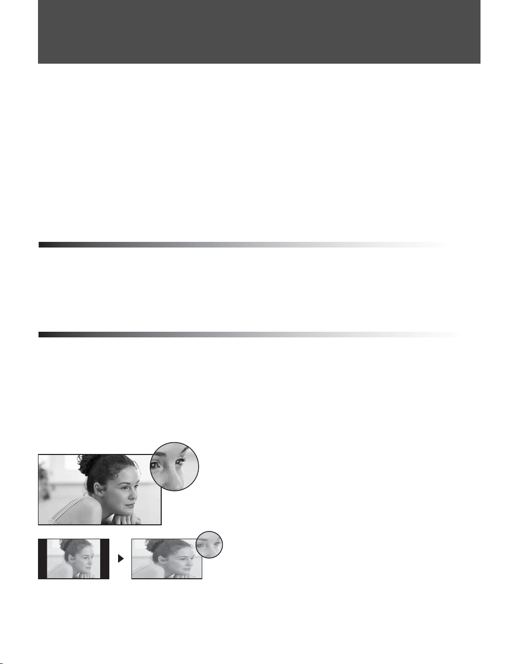
Picture Quality and Aspect Ratio
You can enjoy crisp, clear images, smooth movement and high-impact visuals from 1080i HD signals. When
you compare a high-definition signal to a standard analog signal, you will notice a big difference. The 1080i
HD signals provide more than twice the vertical resolution of the standard TV signal.
High-definition and standard-definition signals are transmitted with different aspect ratios (the width-to-height
ratio of the image). HDTV uses a wider screen than conventional standard-definition TV.
16:9 (high-definition) source
Most HDTV signals use a wide screen aspect ratio of
16:9. The 16:9 fills your BRAVIA screen, maintaining a
crisp, clear, vivid picture.
4:3 (standard-definition) source
Most standard-definition signals use a boxy 4:3 aspect
ratio. When a 4:3 image is displayed on an HDTV, you
will see black bars on the sides. The picture quality ma
not be as sharp as with HD sources.
~
• You can use the Wide Mode function of the TV to adjust the 4:3 image to fit the entire screen (see pages 24 and 32).
• This TV supports signals up to 1080i.
4
Page 5
Getting Started
1. Installing the TV
Getting Started
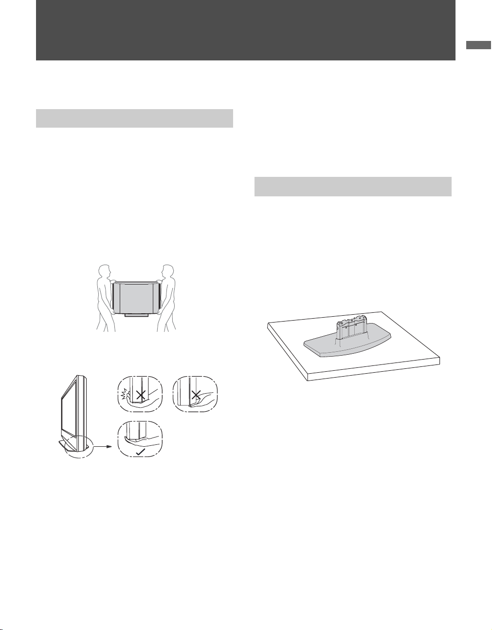
How to Carry the TV
Be sure to follow these guidelines to protect your
properties and avoid causing serious injury.
• Before carrying the TV, disconnect all cables.
• Carrying the large size TV requires two or more
people.
• When you carry the TV, place your hand as
illustrated and hold it securely. Do not put stress
on the LCD panel.
• When carrying the TV, do not subject it to shocks,
vibration or excessive force.
• Place your palm directly underneath but do not
squeeze the panel’s speaker grill area.
The Table-Top Stand for this product is packaged
separately.
Complete the following instructions to install the
TV to the Table-Top Stand before the connection
and setup.
How to Attach the Table-Top Stand
1 Take out the Table-Top Stand from the cushion
and the 4 screws from the accessory bag.
~
• You will find the Table-Top Stand next to the TV
unit.
• Keep the screws away from children.
2 Place the Table-Top Stand onto a level and
stable surface.
(Continued)
5
Page 6
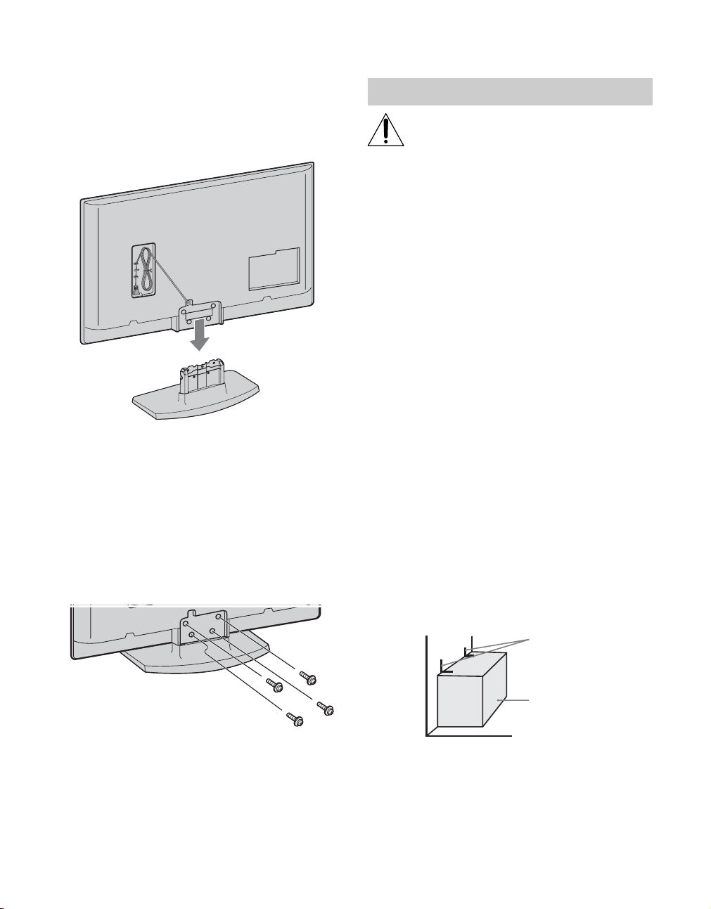
3 Install the TV unit to the Table-Top Stand by
aligning the end of the concave section of the
TV unit to the metal neck of the Table-Top
Stand.
~
• When you carry the TV unit, place your hands as
illustrated on page 5 and hold it securely. Do not
put stress on the LCD panel and the frame around
the screen.
• Be careful to not pinch your fingers or the AC
power cord when you install the TV unit to the
Table-Top Stand.
4 Stabilize the TV unit and the Table-Top Stand
with the supplied 4 screws.
Securing the TV
Sony strongly recommends taking
measures to prevent the TV from toppling
over; as unsecured TVs may topple and
result in property damage, serious bodily
injury or even death.
Prevent the TV from Toppling
s Secure the TV to a wall and/or stand.
s Do not allow children to play or climb on
furniture and TV sets.
s Avoid placing or hanging items on the TV.
s Never install the TV on:
• slippery, unstable and/or uneven surfaces.
• furniture that can easily be used as steps, such
as a chest of drawers.
s Install the TV where it cannot be pulled,
pushed, or knocked over.
s Route all AC power cords and connecting
cables so that they are not accessible to
children.
Recommended Measures to Secure the TV
1 Secure the stand for the TV.
If you use a Sony TV Stand (not supplied), make
sure the TV stand can adequately support the
weight of the TV. Use two angle braces (not
supplied) to secure the stand.
For each angle brace use the appropriate hardware
to:
• attach one side of the angle brace to the wall stud.
• attach the other side to the TV stand.
Angle brace
~
• If you use an electric screwdriver, set the torque for
tightening at approximately 1.5 N
·m {15Kgf·cm}.
6
Stand
Page 7
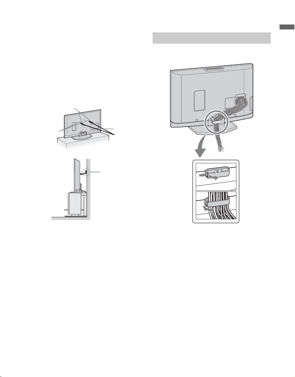
2 Anchor the TV to the Wall.
Use the hardware listed below (not supplied):
•Two M6 × 12-18 mm anchor bolts (screw into
the top-most wall-mount holes located on the
rear of the TV)
• Rope or chain (attach to one M6 anchor bolt)
• Wall-anchor (attach to the wall stud) strong
enough to support the weight of the TV (pass
the rope through the wall-anchor, then attach to
the other M6 anchor bolt).
Anchor bolts
Bundling the Connecting Cables
Getting Started
You can bundle the connecting cables as illustrated
below.
Wall-mount
holes
Rope or
chain
Wallanchor
~
• For further protection, follow these measures to prevent
the TV from toppling over.
1
2
~
• Do not bundle the AC power cord with other connecting
cables.
(Continued)
7
Page 8
Preparation for Wall-Mounting
This TV can be installed on a wall by using a WallMount Bracket (sold separately). Before mounting
the TV on a wall, the Table-Top Stand must be
removed from the TV.
~
• Do not remove the Table-Top Stand for any reason other
than to wall-mount the TV.
• For product protection and safety reasons, Sony
strongly recommends that you use the Wall-Mount
Bracket model designed for your TV and the wallmounting of your TV should be performed by a
Sony dealer or licensed contractor.
Use your TV with the following WALL-MOUNT
BRACKET.
Sony TV Model No.
KDL-26NL140 KDL-32NL140
Sony Wall-Mount
Bracket Model No.
• For bracket installation, refer to the instructions on
page 9 and the instruction guide provided by the WallMount Bracket model for your TV. Sufficient expertise
is required in installing this TV, especially to determine
the strength of the wall for withstanding the TV’s
weight.
• Be sure to store the removed screws and the Table-Top
Stand in a safe place until you are ready to reattach the
Table-Top Stand. Keep the screws away from
children.
SU-WL100 SU-WL500
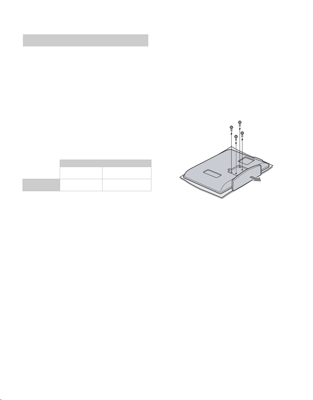
KDL-37NL140
Follow the simple steps below to remove the TableTop Stand:
1 Disconnect all the cables from the TV.
2 Gently lay the TV (face down) onto a level and
stable surface covered with a thick and soft
cloth. Make sure the Table-Top Stand is
hanging over the edge.
3 Remove the 4 screws from behind the TV as
indicated below. Do not remove any other
screws from the TV.
4 Secure the Mounting Hooks to the rear of the
TV. For more details, refer to Installing the
Wall-Mount Bracket and also the Instruction
Guide provided by the Wall-Mount Bracket
model for your TV.
~
• If an electric screwdriver is used, set the torque to
tighten at approximately 1.5 N·m {15Kgf·cm}.
8
Page 9
Installing the Wall-Mount Bracket
To Customers
Your TV can be wall-mounted using a Wall-Mount
Bracket (sold separately). See table on page 8
showing the Wall-Mount Bracket model
appropriate for your TV.
For product protection and safety, Sony strongly
recommends that you use the Wall-Mount
Bracket designed for your TV and wallmounting is performed by a Sony dealer or a
licensed contractor. Do not attempt to install it
yourself. Sony is not liable for any damage or
injury caused by mishandling or improper
installation.
Please provide this installation information as well
as the instruction supplied in the Wall-Mount
Bracket package to your installer.
To Sony Dealers and Licensed Contractors
To avoid injury and property damage, read these
instructions carefully. Periodic inspection and
maintenance is highly recommended to ensure that
TV is securely mounted.
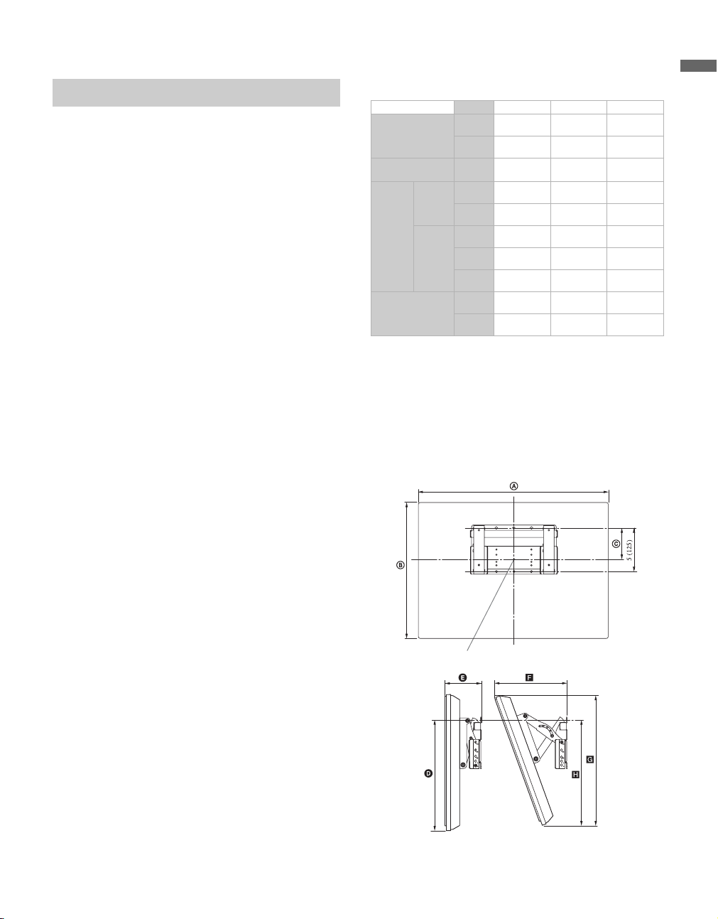
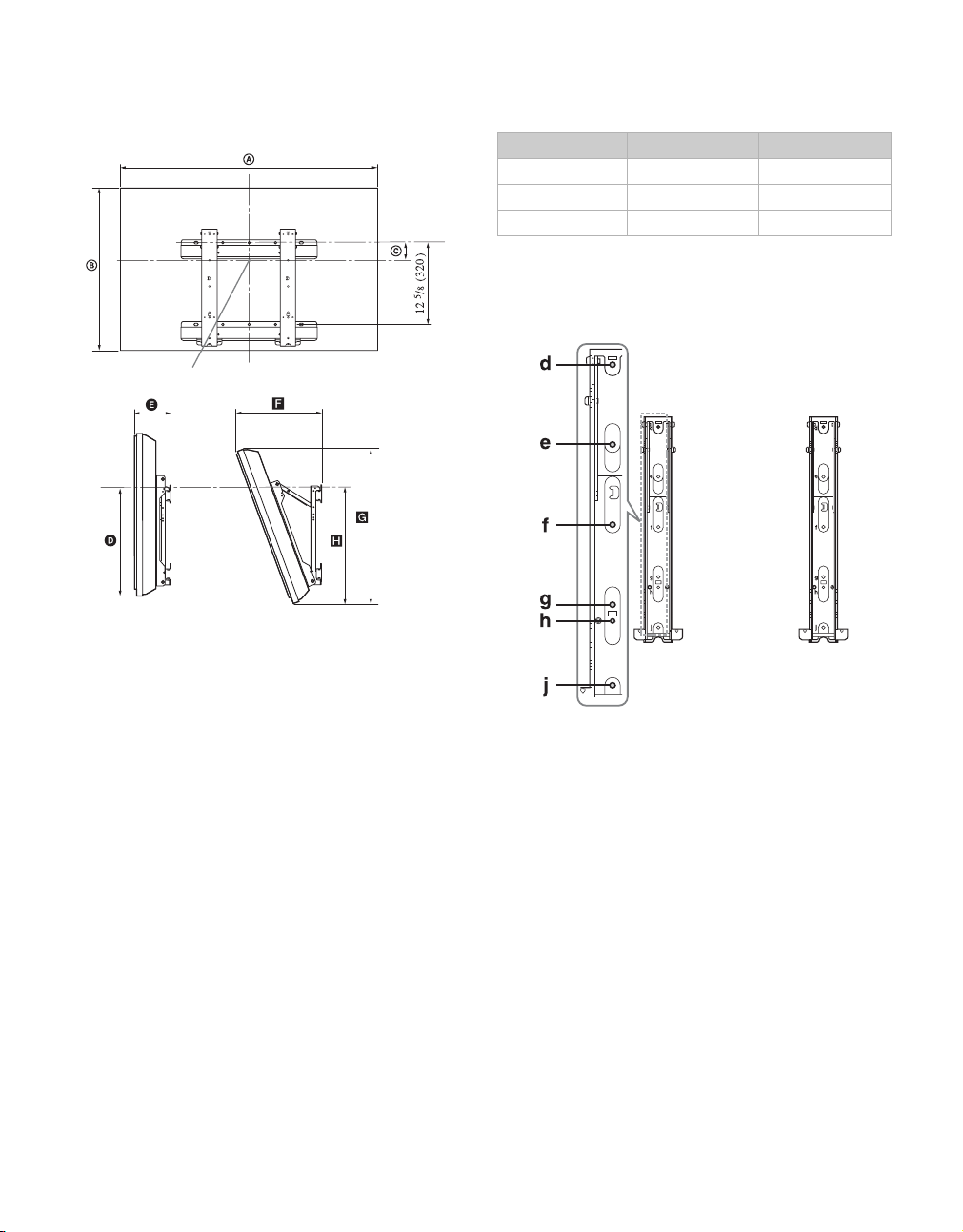
Installation dimensions table
Unit: inches (mm)
TV dimensions
Screen center
dimensions
Length
for each
mounting
angle
Weight
TV Model KDL-26NL140 KDL-32NL140 KDL-37NL140
A
B
C
Angle (0°)
Angle (20°)
D
E
F
G
H
TV
x4
30 3/4
(778)
18 1/2
(468)
3 3/8
(83)
13 1/2
(341)
6 3/8
(160)
10 3/4
(272)
18
(454)
13 3/4
(347)
23 lb.
(10 kg)
92 lb.
(40 kg)
36
(912)
21 1/2
(543)
6 5/8
(168)
18 1/2
(467)
6 3/8
(160)
12 1/4
(309)
20 1/8
(509)
20
(505)
29 lb.
(13.0 kg)
116 lb.
(52.0 kg)
40 1/2
(1,028)
24
(608)
5 1/2
(139)
18 1/2
(467)
6 7/8
(172)
13 1/2
(342)
22 1/2
(570)
20 1/8
(509)
38 lb.
(17.0 kg)
152 lb.
(68.0 kg)
~
• Installation dimensions may differ according to how the
TV is installed.
• The wall must be strong enough to support at least four
times the weight of the TV that you are installing.
For model KDL-26NL140
Unit: inches (mm)
Getting Started
Installing the Wall-Mount Bracket and
Mounting Hooks
1 Open Wall-Mount Bracket package and check
for all the required parts including the
instruction.
2 See Installation dimensions table to determine
the best location for wall-mounting. The wall
must be strong enough to support at least four
times the weight of the TV. Also refer to the
instruction provided with your Wall-Mount
Bracket.
Center line of the screen when installed on the wall
(Continued)
9
Page 10
For models KDL-32NL140 and KDL-37NL140
Unit: inches (mm)
Center line of the screen when installed on the wall
3 Install the Base Bracket on the wall. Refer to
the instruction provided with your Wall-Mount
Bracket.
4 Disconnect all cables and remove the Table-
Top Stand. See page 8 for details.
5 Install Mounting Hooks on the TV. See
diagrams and table for Screw and Hook
locations.
Hook locations diagram/table
TV Model Screw location Hook location
KDL-26NL140 -a
KDL-32NL140 e, g c
KDL-37NL140 d, g b
Screw location
When installing the Mounting Hooks on the TV.
For models KDL-32NL140 and KDL-37NL140
10
Page 11
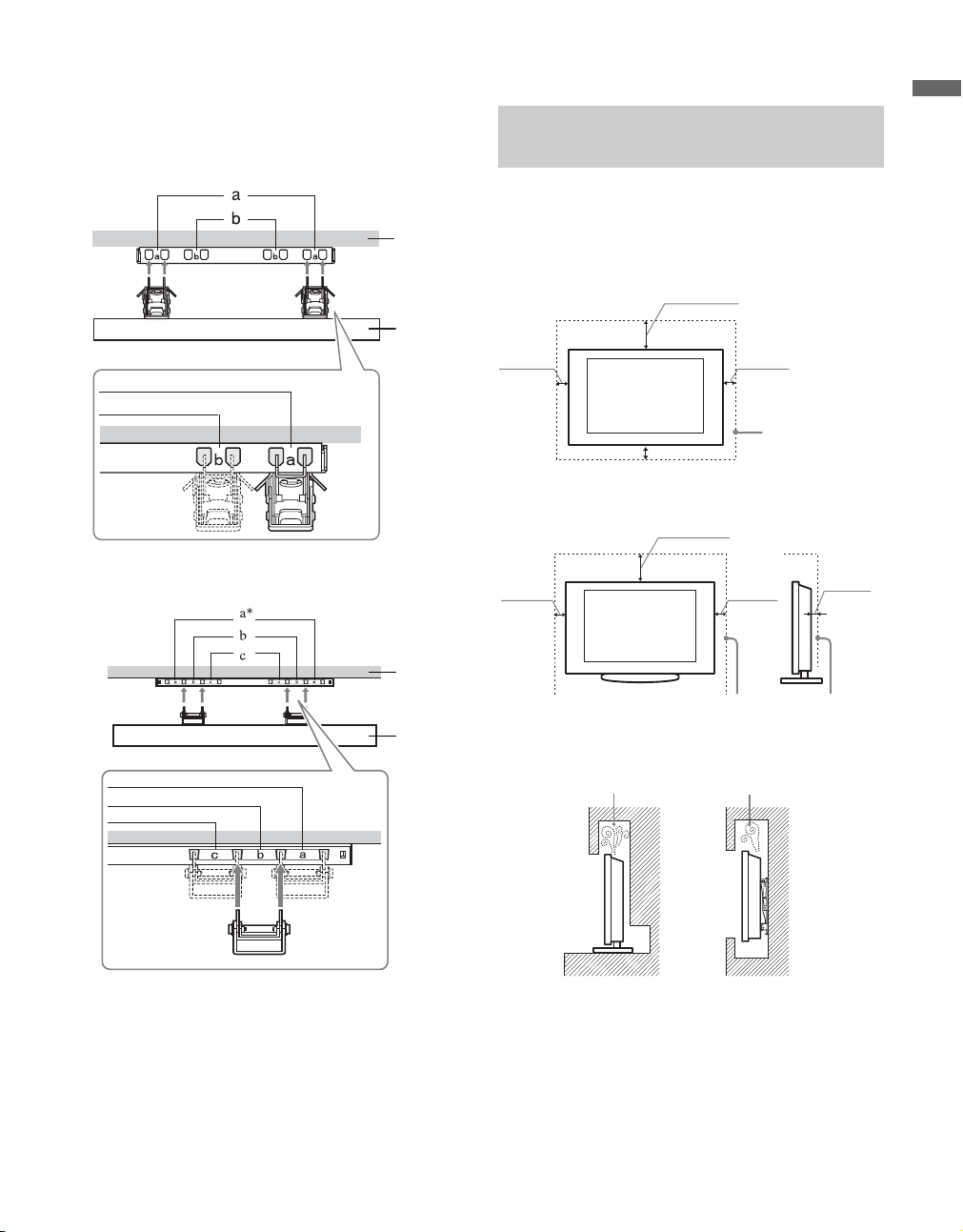
Hook location
When installing the TV onto Base Bracket.
For model KDL-26NL140
Wall
TV
For models KDL-32NL140/KDL-37NL140
When Installing the TV Against a Wall or Enclosed Area
Make sure that your TV has adequate air
circulation. Allow enough space around the TV as
shown below.
Installed on the wall
7
11
inches
/
8
(30 cm)
8
inches
4 inches
(10 cm)
Leave at least
this much space
around the set.
4 inches
(10 cm)
3
inches
/
2
8
(6 cm)
4 inches
(10 cm)
4 inches (10 cm)
Installed with Table-Top Stand
7
11
/
(30 cm)
4 inches
(10 cm)
Getting Started
Wall
TV
* Hook position “a” cannot be used for the models in the table above.
Leave at least this much space
around the set.
Never install the TV set as follows:
Air circulation is blocked.
Air circulation is blocked.
Wall Wall
~
• Inadequate air circulation can lead to overheating of the
TV and may cause damage to your TV or cause fire.
11
Page 12
2. Locating Inputs and Outputs
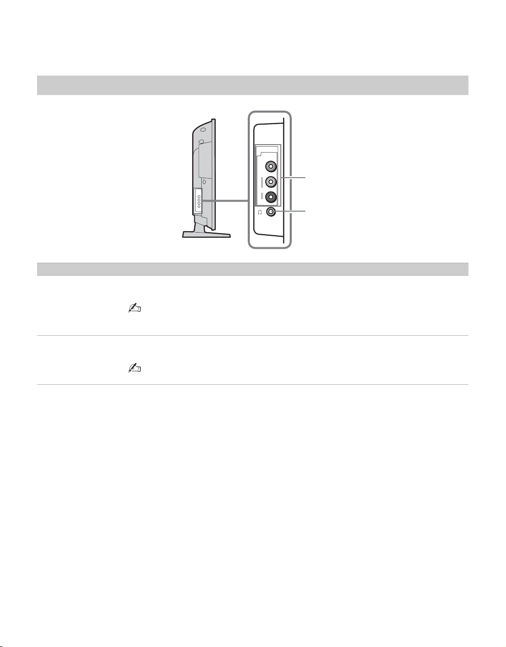
Side Panel
Item Description
1
VIDEO IN 2
VIDEO/
L (MONO)AUDIO-R
2 Headphone
jack
Connects to the composite video and audio output jacks on your camcorder or other video
equipment such as a DVD or video game equipment.
• If you have mono equipment, connect its audio output jack to the TV’s L (MONO) audio
input jack.
Connects to your headphones. If your headphones do not match the jack, use a suitable plug
adapter (not supplied).
VIDEO IN
2
VIDEO
L
(MONO)
AUDIO
R
1
2
12
• While headphones are connected, the TV speakers are muted.
Page 13
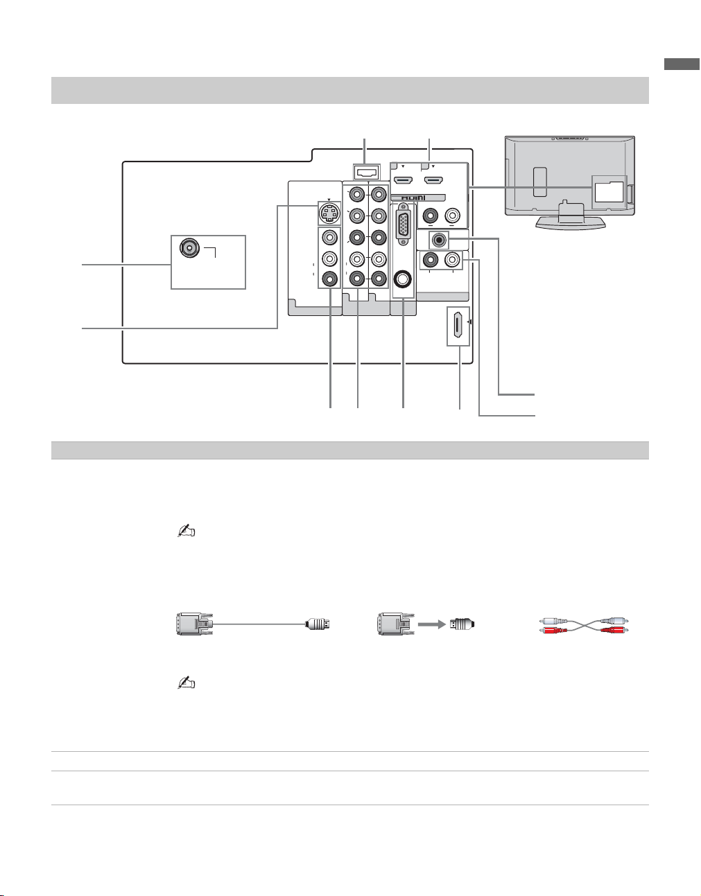
Rear Panel
9
Getting Started
3
CABLE/
ANTENNA
4
Item Description
1 HDMI IN 1/2
R-AUDIO-L
HDMI (High-Definition Multimedia Interface) provides an uncompressed, all-digital
audio/video interface between this TV and any HDMI-equipped audio/video equipment, such
as DVD player, a set-top box, A/V receiver and Blu-ray Disc player as well as PC. HDMI
supports enhanced or high-definition video plus digital audio.
S VIDEO
VIDEO
(MONO)
AUDIO
VIDEO IN
L
R
2
SERVICE
ONLY
Y
B
P
PR
L
AUDIO
R
112
COMPONENT IN
(1080i/720p/480p/480i)
56
1
RGB
AUDIO
PC IN
7
1
2
IN
AUDIO OUT
DMPORT
AUDIO
LR
DIGITAL
AUDIO
OUT
(COAXIAL)
LR
(FIX)
8
0
• If the equipment has a DVI and not an HDMI connector, use a DVI to HDMI cable or adapter
to connect the DVI output to either HDMI IN 1 or HDMI IN 2 input, and connect the audio
jacks to the AUDIO (L/R) jacks below the HDMI IN 2. (DVI connector is for video signals
only, the Audio jacks provide support for the audio.)
DVI-to-HDMI cable DVI-to-HDMI adapter Audio cable
• The HDMI input has been fitted to suit A/V equipment such as DVD players for 480i, 480p,
720p and 1080i signals. PC generated signals may not be rendered as expected due to scaling
factors. For better PC view, use the PC IN (RGB IN) input. Note that this TV displays all
video input signals in a resolution of 1,366 dots × 768 lines.
2 SERVICE ONLY This USB port is for service only.
3 CABLE/
RF input that connects to your cable or VHF/UHF antenna.
ANTENNA
(Continued)
13
Page 14
Item Description
4 VIDEO IN 1
S VIDEO
5 VIDEO IN 1
VIDEO/
L(MONO)AUDIO-R
6 COMPONENT
IN 1/2
(1080i/720p/
480p/480i)/
L-AUDIO-R
7 PC IN
(RGB/AUDIO)
8 DMPORT Connects to DIGITAL MEDIA PORT adapter (not supplied) to display photos and videos or
9 AUDIO OUT
(FIX) R/L
0 DIGITAL AUDIO
OUT (COAXIAL)
Connects to the S VIDEO output jack of your DVD or other video equipment that has
S VIDEO. S VIDEO provides better picture quality than composite video (5). S VIDEO
does not provide sound, you need to connect the audio cables.
Connects to the composite video and audio output jacks on your A/V equipment such as a
DVD or other video equipment. A second composite video and audio input (VIDEO IN 2) is
located on the left side panel of the TV.
Connects to your DVD player’s or digital set-top box’s component video (YP
(L/R) jacks. Component video provides better picture quality than the S VIDEO (4) or the
composite video (5) connections.
Connects to a personal computer’s video output connector using HD15-HD15 cable (analog
RGB, not supplied).
See “PC Input Signal Reference Chart” on page 17 for the signals that can be displayed.
• For some Apple Macintosh computers, it may be necessary to use an adapter (not supplied).
If this is the case, connect the adapter to the computer before connecting the HD15-HD15
cable.
play music from a Portable Player to your TV (see page 20 for more details).
• Available DIGITAL MEDIA PORT adapters vary in each area.
• Do not connect an adapter other than the DIGITAL MEDIA PORT adapter.
Connects to the left and right audio input jacks of your audio or video equipment. You can use
these outputs to listen to your TV’s audio through your stereo system.
Connects to the coaxial audio input of a digital audio equipment that is PCM/Dolby Digital
compatible.
PR) and audio
B
• Component video (YP
this TV displays all format types of picture in its native resolution of 1,366 dots × 768 lines.
) or HDMI connection are necessary to view 480i, 480p, 720p, and 1080i formats. Note that
BPR
14
Page 15
3. Connecting the TV
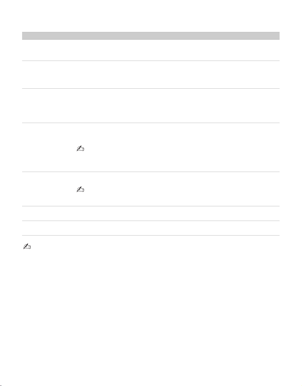
Cable System and/or VHF/UHF
Cable or VHF/UHF (or VHF only)
Getting Started
75-ohm coaxial cable
(not supplied)
CABLE/ANTENNA input
Rear of TV
• It is strongly recommended that you connect the antenna/cable input using a 75-ohm coaxial cable (not supplied) to
receive optimum picture quality. A 300-ohm twin lead cable can be easily affected by radio frequency interference,
resulting in signal degradation.
Cable and VHF/UHF (or VHF only)
If you want to watch both cable and antenna (over-the-air) programming, you will need to use an optional AB RF Switch (not supplied) to switch between the cable and over-the-air antenna programming, as shown.
A-B RF
Switch
Cable
Antenna
A
B
CABLE/ANTENNA input
Rear of TV
• Be sure to set Cable setting to On or Off in Channel menu for the type of input signal you choose (see page 33 for
more details).
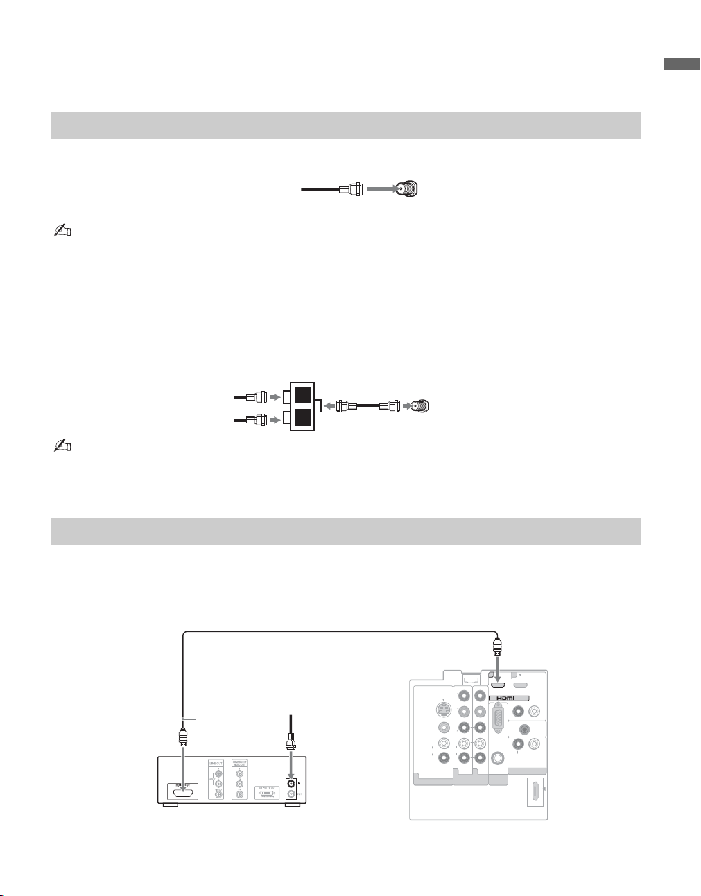
HD Cable Box/HD Satellite Box
You can also enjoy high-definition programming by subscribing to high-definition cable service or highdefinition satellite service. For the best possible picture, connect these components to your TV via the
HDMI or component video (with audio) input on the back of your TV.
Shown with HDMI Connection
HDMI cable
HD cable box/HD satellite box
CATV/
Satellite
antenna cable
Rear of TV
SE RV IC E
ON LY
Y
P
S VIDEO
VIDEO
P R
L
L
(MONO)
AUDIO
AUDIO
R
R
1 1 2
VIDEO IN
B
COMPONENT IN
(1080i/720p/480p/480i)
1
AUDIO
PC IN
RGB
DMPORT
2
IN
R
A UDI O
A UDIO OUT
DIGITAL
AUDIO
OUT
(COAXIAL)
L R
(FIX )
L
(Continued)
15
Page 16

Shown with DVI Connection
CATV/Satellite
antenna cable
DVI-to-HDMI cable
HD cable box/HD satellite box
L
AUDIO-L
(white)
AUDIO-R
(red)
S VIDEO
VIDEO
(MONO)
AUDIO
VIDEO IN
L
R
Rear of TV
SE RV IC E
ON LY
Y
B
P
P R
L
AUDIO
R
1 1 2
COMPONENT IN
(1080i/720p/480p/480i)
RGB
AUDIO
PC IN
DMPORT
2 1
2
IN
R
A UDI O
A UDIO OUT
DIGITAL
AUDIO
OUT
(COAXIAL)
L R
(FIX )
Audio cable
~
• If the equipment has a DVI and not an HDMI connector, use a DVI to HDMI cable or adapter to connect the DVI
output to either HDMI IN 1 or HDMI IN 2 input, and connect the audio jacks to the AUDIO (L/R) jacks below the
HDMI IN 2 (DVI connector is for video signals only, the audio jacks provide support for the audio).
Shown with Component Connection
HD cable box/HD satellite box
CATV/
Satellite antenna cable
16
1
S VIDEO
VIDEO
(MONO)
AUDIO
VIDEO IN
Rear of TV
RGB
AUDIO
PC IN
2 1
IN
R
A UDIO OUT
DMPORT
A UDI O
L
DIGITAL
AUDIO
OUT
(COAXIAL)
L R
(FIX )
SE RV IC E
ON LY
Y
B
P
P R
L
L
AUDIO
R
R
1 2
COMPONENT IN
(1080i/720p/480p/480i)
Y (green)
B (blue)
P
R (red)
P
AUDIO-L (white)
AUDIO-R (red)
Component
video cable
Audio cable
Page 17

PC
Use the TV as a monitor for your PC.
Shown below with the HD15 to HD15 connection. This TV can also be connected to a PC with DVI or
HDMI output. (Refer to the supplied Quick Setup Guide.)
Rear of TV
RGB
AUDIO
PC IN
DMPORT
2 1
IN
R
A UDI O
A UDIO OUT
L
DIGITAL
AUDIO
OUT
(COAXIAL)
L R
(FIX )
HD15-HD15
cable (analog
RGB)
Audio cable (stereo mini plugs)
S VIDEO
VIDEO
L
(MONO)
AUDIO
R
VIDEO IN
SE RV IC E
ON LY
Y
P
B
P
R
L
AUDIO
R
1 1 2
COMPONENT IN
(1080i/720p/480p/480i)
~
• Connect the PC IN jack to the PC using the HD15-HD15 cable with ferrite core (analog RGB) and audio cable
(page 14).
Getting Started
PC Input Signal Reference Chart
After connecting the PC to the TV, set the output signal from the PC according to the chart below.
Resolution
Signals Horizontal
(Pixel)
VGA 640 × 480 31.5 60 VG A
SVGA
XGA
WXGA
640 × 480 37.5 75 VES A
800 × 600 37.9 60 VESA Guidelines
800 × 600 46.9 75 VESA
1,024 × 768 48.4 60 VESA Guidelines
1,024 × 768 56.5 70 VESA
1,024 × 768 60.0 75 VESA
1,280 × 768 47.8 60 VESA
1,360 × 768 47.7 60 VE S A
× Vertical
(Line)
Horizontal
frequency (kHz)
Ver tical
frequency (Hz)
Standard
~
• This TV’s PC input does not support Sync on Green or Composite Sync.
• This TV’s PC VGA input does not support interlaced signals.
• For the best picture quality, it is recommended to use the signals (boldfaced) in the above chart with a 60 Hz vertical
frequency from a personal computer. In plug and play, signals with a 60 Hz vertical frequency will be detected
automatically (PC reboot may be necessary).
(Continued)
17
Page 18

Other Equipment
Personal
computer
rear of TV
Blu-ray
Disc Player/
“PS3”
S VIDEO
VIDEO
L
(MONO)
AUDIO
R
VIDEO IN
SERVICE
ONLY
AUDIO
Y
P
PR
L
R
112
B
COMPONENT IN
(1080i/720p/480p/480i)
DVD
player
RGB
AUDIO
PC IN
DMPORT
21
IN
AUDIO
AUDIO OUT
Digital
satellite
receiver
LR
DIGITAL
AUDIO
OUT
(COAXIAL)
LR
(FIX)
Digital
cable box
Audio
system
CABLE/
ANTENNA
Headphones
Camcorder
VIDEO IN
2
VIDEO
L
(MONO)
AUDIO
R
CABLE/ANTENNA
Digital audio equipment
VCR
Game system
Digital
recorder
Analog audio equipment
(A/V Receiver/Home Theater)
~
• Refer to the Quick Setup Guide (supplied) when connecting other equipment to your TV.
18
DIGITAL MEDIA
PORT adapter for
portable player
Page 19

4. Setting Up the Channel List -
Initial Setup
After you finish connecting your TV, you need to
run Initial Setup, which automatically sets up
available channels. The Initial Setup screen
appears when you turn on your TV for the first
time. If you do not want to set up the channels at
this time, you can do it later by selecting the Auto
Program option in the Channel menu (see page
33).
1 Press to turn on the TV.
2 Press V/v to highlight the desired language,
3 Please connect cable or antenna, then select
POWER
The Initial Setup screen appears.
Initial Setup
Press to choose a language.
Please select your language:
then press .
Yes to run Auto Program.
Getting Started
To run Auto Program at a later time
❑ Use the Auto Program feature at Channel
menu as described on page 33.
To display the picture in your preferred
aspect ratio
❑ Select the proper Wide Mode as described on
pages 24 and 32.
~
• You may want to set up convenient features such as
Favorites (see page 28), Show/Hide Channels
(see page 33), Label Channels (see page 33) when
Auto Program is completed.
~
• If you want to run Auto Program later, select No.
• If you have both cable and antenna available, please
connect cable first.
• IMPORTANT: You must perform Auto Program
after cable or antenna is connected. If you cancel
Auto Program some channels may not be
available.
4 Follow the help text provided on the screen to
run Auto Program. Auto Program will
scan for available channels from signal source
directly connected to the TV’s
CABLE/ANTENNA input.
5 When Auto Program is complete, select OK
to finish the Auto Program process.
19
Page 20

Exploring Fun Features
Using BRAVIA Theatre Sync™ with Control for HDMI
This TV is equipped with BRAVIA Theatre
Sync™. The Control for HDMI function enables
BRAVIA Theatre Sync to allow communication
between Sony TV’s and Sony equipment. Only
Sony equipment with Control for HDMI
capability is supported.
To connect Sony equipment with Control for
HDMI
Use an HDMI cable that bears the HDMI logo for
connection. See pages 15 to 18 or see the HDMI
connection shown in the Quick Setup Guide
provided with the TV documentation.
Setting the Control for HDMI
In order for the function of Control for HDMI to
operate, the TV and other Sony equipment with
Control for HDMI function must be setup (see
page 38). For other equipment, refer to the
operating instruction for that equipment.
Control for HDMI available with your TV
The following operations are available after you
connect the Sony equipment with Control for
HDMI function to your TV:
• Automatically turn off the connected equipment
when you turn off the TV.
• The TV will automatically turn on and tunes to the
respective HDMI input when the connected
equipment is turned on by One-Touch-Play.
• Equipment listed under External Inputs will
turn on automatically when selected.
When you connect a Sony A/V receiver with
BRAVIA Theatre Sync function to your TV, the
following additional operation is possible:
• By pressing on the remote control, it turns on
and searches for external audio system. When the
BRAVIA Theatre Sync audio system is on, the
internal speakers of the TV will turn off and the
Picture Mode will change automatically to
Cinema.
THEATER
Using DIGITAL MEDIA PORT adapter
Connecting a DIGITAL MEDIA PORT adapter,
lets you display photos and videos or play music
from a Portable Player to your TV.
The equipment’s menu may be displayed on the TV
and can be controlled via the TV’s remote control.
By pressing V/v, B/b, and you can go
through the equipment’s menu. Use V/v (to go
up/down), B (to left), b (to go right or to play),
(to select an item or to play), and (to go previous
menu window).
~
• Viewing the equipment’s menu on the TV and
controlling it via the TV’s remote control depends on
the equipment; refer to the equipment’s operating
instructions.
• Available DIGITAL MEDIA PORT adapters vary in
each area.
• Do not connect an adapter other than the DIGITAL
MEDIA PORT adapter.
• Depending on the type of DIGITAL MEDIA PORT
adapter, images may also be output. In this case, the
system outputs only a composite video signal.
• Check compatibility between portable audio and the
DIGITAL MEDIA PORT adapter.
20
Page 21

Remote Control and TV Controls/Indicators
Inserting Batteries
Push to open
When Using the Remote Control
Insert two size AA batteries (supplied) by matching
e and E on the batteries to the diagram inside the
battery compartment of the remote control.
Follow the guidelines below
• Point your remote control directly at the IR sensor
located on your TV.
• Make sure that no objects are blocking the path
between the remote control and IR sensor on your
TV.
• Fluorescent lamps can interfere with your remote
control; try turning off the fluorescent lamps.
• If you are having troubles with the remote control,
reinsert or replace your batteries and make sure
that they are correctly inserted.
Remote Control and TV Controls/Indicators
21
Page 22

Remote Control
1
2
3
4
5
SOUND
GUID
E
TOOLS
MENU
•The 5 and CH + buttons have a tactile dot. Use them as a reference when
operating the TV.
Button Description
1 DISPLAY Press once to display the information pertaining to the
channel and/or program when available. The OSD (On
Screen Display) will time out in a few seconds or press again
to immediately turn off the display.
2 SLEEP Press repeatedly until the TV displays the time in minutes
(Off, 15, 30, 60 or 120 minutes) that you want the TV to
remain on before shutting off. To cancel Sleep, press
repeatedly until Off appears.
3 THEATER Press to turn on and off the Theater Mode. The picture
settings will be set for a cinema-like experience and the
audio will be switched to the audio output of the attached
speakers of your BRAVIA Theatre Sync audio system. Your
BRAVIA Theatre Sync audio system must be connected by
an HDMI connection to your TV (see page 15 for details).
4 SOUND Press repeatedly to step through the Sound Mode settings:
Dynamic, Standard, Game, Clear Voice, Custom.
These Sound Mode settings can be also accessed in the
Sound menu (see pages 31).
5 PICTURE Press repeatedly to cycle through the available picture
modes: Vivid, Standard, Cinema. The picture modes can
also be accessed in the Picture menu. For details, see page
30.
22
Page 23

6
7
8
9
q;
qa
qs
qd
GUID
SOUND
Button Description
6 GUIDE
qf
(For all
channels
including
E
Digital/Analog
channels)
TOOLS
MENU
Press to display the Guide when you are watching channels
(if it is available from the station).
Using the Guide
The Guide allows you to select the channels from a channel
list; also provides information about the current program
being shown on each channel.
Info
Banner
Channel
list
Make Way for Ducks!
Series follows the aquatic misadventures of Henry and Riley, two wayward ducks on a unique mission.
TV-G
2
ON-3
3
FOX6
6
XWV-10
10
XEW-12
12
KPBS
15
KPBS-HD
15.1
V-me
15.2
AZ-21
21
AZT-27
27
TEL-33
33
NBC-39
39
FR-40
40.1
CH-41
41
(0:29 Remaining)
1080i HD Full16:9
KPBS-HD
15.1
12:00 AM
Remote Control and TV Controls/Indicators
• Program information in the guide is provided by the
broadcasters. As a result, it may sometimes include only
the channel number, without a program title or
description.
7 RETURN Press to go back to the previous screen or exit from the
screen when displaying menu items and settings.
8 MENU Press to display the menu with TV functions and settings.
See “Using the TV Menus” on page 27.
9 CC Press to turn on and off the Closed Captions (CC). To
change or customize the CC display, see page 37.
0 0-9/ENT Press - to select a channel; the channel changes after
few seconds. Press to change channels immediately.
qa Use with - and to select digital channels. For
example, to enter 2.1, press , , and .
2
1
qs VOL +/– Press to adjust the volume.
qd MUTING Press to mute the sound. Press again or press VOL + to
restore the sound.
qf POWER Press to turn on and off the TV.
(Continued)
23
Page 24

SOUND
GUID
Button Description
qg WIDE Press repeatedly to step through the Wide Mode settings:
Wide Zoom, Normal, Full, Zoom. The Wide Mode
settings can be also accessed in the Screen menu (see page
32).
E
qg
Changing the Wide Screen Mode
4:3 Original source
Standard-definition source
16:9 Original source
High-definition source
MENU
TOOLS
mm
Wide Zoom Wide Zoom
Normal Normal
This mode is not available
Full Full
Zoom Zoom
~
• When the TV receives a 720p or 1080i signal, Normal
cannot be selected.
24
Page 25

Button Description
qh INPUT Press to display the list of External Inputs and TV mode.
Press repeatedly to toggle through the inputs.
SOUND
GUID
E
qh
qj V/v/B/b Press V/v/B/b to move the on-screen cursor. Press to
qj
Inputs labels.
select/confirm an item.
• See page 37 (Label Inputs) on setting up the External
Remote Control and TV Controls/Indicators
qk TOOLS This button supports different functions depending on the
TOOLS
qk
MENU
ql
w;
condition. When PC input is active, press to view a
channel at the same time as a PIP (picture in picture) screen
(see page 29 for details). When antenna input is active and
the broadcast includes Regional Digital Ratings, press to
view the list of special ratings.
When an HDMI controlled equipment is active, press to
access the equipment menu, if the equipment supports the
function.
ql JUMP Press to alternate between two channels. The TV will
alternate between the current channel and the last channel
tuned with the buttons - and on the remote control.
w; FAVORITES This feature lets you create and choose a list of up to
8 favorite channels.
Press V/v to select the option Add to Favorites, and press
to add the current channel to your Favorites list.
wa
•Your Favorites list will be cleared each time you run
Auto Program (see pages 33).
wa CH +/– Press to scan through channels. To scan quickly through
channels, press and hold down either +/–.
25
Page 26

TV Controls/Indicators
Item Description
1 MENU
2
INPUT
3
– VOLUME +
4
– CHANNEL +
5 POWER Press to turn on and off the TV.
6 TIMER/PIC OFF
LED
7 STANDBY LED
8 POWER LED Lights up in green when the TV is turned on.
9 (IR) Infrared
Receiver
Light Sensor
Press to display the menu with TV functions and settings (see “Using TV Menus” on page 27).
Press to display the External Inputs list, toggle through the list and select your desired
input.
menu
In the
Press to adjust the volume. In the
Press to scan through channels. In the
Lights up in amber when the timer is set. When the timer is set, this LED will remain lit even
if the TV is turned off. For details, see page 38. If the LED blinks in red continuously, this
may indicate the TV needs servicing (see contacting Sony information on the back cover).
Lights up in green when the Backlight feature is activated.
Lights up in red when your TV is in PC standby mode.
Receives IR signals from the remote control.
Senses room light level and adjusts the screen brightness accordingly (see page 30 for details).
Do not put anything near the sensor, as its function may be affected.
screen, this button serves as confirming the selection or setting.
menu
screen, these buttons serve as left/right buttons.
menu
screen, these buttons serve as up/down buttons.
• Make sure that the TV is turned off before unplugging the power cord. Unplugging the power cord while the TV is
turned on may cause the POWER LED to remain lit for up to 20 seconds or may cause the TV to malfunction.
26
Page 27

Using TV Menus
SOUND
GUIDE
MENU
TOOLS
MENU provides one button access for controlling your TV. It enables you to perform a variety of tasks intuitively with a
control panel on the screen.
Navigating through TV Menus
1 Press on the remote control to display the menu options.
2 To highlight a menu option press B, then press V/v to go through
2
4
3
,
,
1, 5
Menu Descriptions
the menus.
3 To select an option press or b.
4 Press V/v to select or adjust your desired option, then press .
5 To exit press .
Using TV Menus
Shortcuts
Picture
Sound
Screen
The Shortcuts menu lets you select:
External Inputs, Favorites, and
shortcuts to Wide Mode,
Clock/Timers, Parental Lock,
Closed Captions (
you can also select PC-PIP function
from this menu.
The Picture menu is used to fine tune
the image quality and allows you to
customize several parameters for
optimal viewing. Select from: Picture
Mode, Backlight, Picture,
Brightness, Color, Hue, Color
Temp (Color Temperature),
Sharpness, Advanced Settings or
Reset.
The Sound menu allows you to fine
tune and change audio. Select from:
Sound Mode, Effect, Steady
Sound, Treble, Bass, Balance,
Speakers, Backlight, Alt.
Audio/MTS or Reset.
The Screen menu allows you to change
the proportions of the screen. Select
from: Wide Mode, Auto Wide
Default, Vertical Center, Vertica l
Size or Phase.
CC
) and Cable;
, 4:3
Channel
Parental Lock
Setup
The
Channel
maintenance to the channel options.
Select from:
Digital Channels
Show/Hide Channels
Channels
The Parental Lock feature allows you
to set up the TV to block programs
according to their content and rating
levels. Use - on the remote
control to enter a four-digit password.
The first time you create a password,
confirm the password by entering it
again.
The Setup menu provides you additional
features like: Closed Captions (CC),
Info Banner, Label Inputs, Skip
Inputs, Clock/Timers, Language,
Auto Sort Control, Control for
HDMI, Update Control for HDMI List
or Product Support.
menu
is used to provide
Favorites, Cable, Add
,
Auto Program,
,
or
Diagnostics
Label
.
(Continued)
27
Page 28

Using the Shortcuts Menu
External Inputs This feature lets you select the external inputs connected to your TV.
1 Press V/v to choose an external input from the list of 9 inputs.
2 To select press .
• To exit from external inputs list, press .
• To change external inputs again, repeat steps 1-2.
• To go back to channels, press CH +/–
select TV; or press to select a channel from your Favorites
FAVOR ITE S
• You can also access the External Inputs list directly by pressing without having to
navigate through the menu.
Favorites This feature lets you create and choose a list of up to 8 favorite channels.
Press V/v to select the option Add to Favorites, and press to add the current channel
to your Favorites list.
• You can also press button to see your Favorite Channel list.
FAVOR ITE S
Wide Mode This option is a direct shortcut to the Screen menu to adjust the picture size in the Wide
Mode option (see page 32).
Clock/Timers This option is a shortcut to adjust Clock/Timers on Setup menu (see page 38).
Parental Lock This option is a shortcut to the Parental Lock menu which allows you to enter a password
to block channels (see page 34).
Closed Captions (CC) This option is a shortcut to Closed Captions (CC) screen on Setup menu (see page 37).
Cable This option is a shortcut to adjust Cable setting on Channel menu (see page 33).
MENU
to go through the channels or repeat steps 1-2 and
list.
INPUT
28
Page 29

PC-PIP This PIP (picture in picture) feature provides PC input signal and TV channels, allowing
you to view two pictures simultaneously. When you select this feature from Shortcuts
menu, the PC-PIP will appear with a Sub Window to see TV channels at the same time.
Main Window
(PC)
• You need a PC input signal to use PC-PIP function.
• PIP window is only supported for the PC resolutions described on the PC Input Signal
Reference Chart (see page 17).
• To turn on or off the Sub Window on the screen press from the remote control while
using the PC input.
• You can also select PC input from the External Inputs list. Press , select
External Inputs, then select PC input from the list.
To Change Channels in the Sub Window
Press CH +/– to change the channels or enter the channel number using the - numeric
buttons.
To Exit from PC-PIP (PC input)
1 Press and select External Inputs on the Shortcuts menu.
MENU
Sub Window
(TV Channel)
MENU
2 From External Inputs list, select TV input to return to TV channels.
• To exit from PC-PIP, you can also select a channel from your Favorites channels list on
the Shortcuts menu.
• When the PC input signal is selected with the Sub Window active, you can only see TV
channels, other external inputs are not available for this view (like VCR/DVD).
• Closed Captions (CC) is not available in the Sub Window.
• Parental Lock feature will work in the Sub Window; a padlock will appear on the
blocked channels.
Using TV Menus
(Continued)
29
Page 30

Using the Picture Menu
Picture Mode
Customized picture
viewing
Backlight Press B/b to brighten or darken the backlight, then press to set.
Picture Press B/b to increase or decrease picture contrast, then press to set.
Brightness Press B/b to brighten or darken the picture, then press to set.
Color Press B/b to increase or decrease color intensity, then press to set.
Hue Press B/b to increase or decrease the green or red tones, then press to set.
Color Temp (Color
Temperature)
Sharpness Press B/b to sharpen or soften the picture, then press to set.
Advanced Settings Noise Reduction Reduces the noise level of connected equipment, and the
Reset Resets the current Picture Mode setting to factory default values.
Vivid For enhanced picture contrast and sharpness.
Standard For standard picture settings. Recommended for home entertainment.
Cinema For viewing film-based content. Most suitable for viewing in a theater-
like environment.
Cool Gives the white colors a bluish tint.
Neutral Gives the white colors a neutral tint.
Warm 1, 2 Gives the white colors a reddish tint.
CABLE/ANTENNA input.
Black Corrector Enhances black areas of the picture for stronger contrast.
Gamma Adjusts the balance between the light and dark areas of the picture.
Clear White Emphasizes white and light colors.
Live Color Makes colors more vivid and reproduces clear skin tones.
Light Sensor Select On to enable the automatic picture (screen) brightness control.
The light sensor measures the room brightness which allows the TV to
automatically adjust the backlight brightness based on the picture
settings and the ambient room light conditions.
• Be sure not to put anything around the sensor, as its function may be
affected.
• In low light the range of the backlight control is reduced when
Sensor
is set to On
.
Light
30
Page 31

Using the Sound Menu
Sound Mode Dynamic Enhances the sound of action movies, sports events and musical
videos.
Standard Standard sound optimized for home use.
Game Enhances the video games sound.
Clear Voice Enhances the voice sound; recommended for television news and
documentary programs.
Custom Allows you to customize Tre bl e and Bass sound settings.
Effect TruSurround XT Produces realistic surround sound experience.
Steady Sound On Stabilizes the volume across all programs and commercials.
Off Turns off Steady Sound.
Treb le Press B/b to increase or decrease higher-pitched sounds, then press to set.
Bass Press B/b to increase or decrease lower-pitched sounds, then press to set.
Balance Press B/b to emphasize left or right speaker balance, then press to set.
Speakers Select to turn on or off the internal speakers.
Backlight Turns off the Backlight to conserve power while the audio is left on.
Alt. Audio/MTS This Audio feature for current program lets you select from 8 options of alternate audio (if it
is available). You can select from English, Español (Spanish), Français (French) or
Audio 4, 5, 6, 7, 8 audio available options.
• Alternate Audio is disabled for analog signals and for digital signals that do not have
altenate audio streams.
Mono Select for mono reception. Use to reduce noise during weak stereo/
broadcasts.
Stereo Select for stereo reception when viewing a program broadcast in
stereo.
Auto SAP Select to automatically switch the TV to second audio programs when
a signal is received. If no SAP signal is present, the TV remains in
Stereo mode.
Reset Resets the current Sound settings to factory default values.
Using TV Menus
(Continued)
31
Page 32

Using the Screen Menu
Wide Mode These options allow you to change the proportion of the screen.
Wide Zoom Select to enlarge the picture uniformly.
Normal Select to display 4:3 pictures in original size when the original source
is 4:3.
• Normal is not available when you are watching 1080i or 720p in High-Definition source.
Full Select to enlarge the picture horizontally to fill the screen when the
original source is 4:3 (standard-definition source). When the original
source is 16:9 (high-definition source), select this mode to display 16:9
picture in original size.
Zoom Select to enlarge the original picture without distorting the aspect ratio.
• If you press
Auto Wide On Select to have the screen automatically change to the screen mode
Off Select to turn off the Auto Wide option.
4:3 Default Select the default Screen Mode to use for 4:3 sources.
Wide Zoom Select to enlarge the 4:3 picture to fill the 16:9 screen, keeping the
Normal Select to display the 4:3 picture in its original size.
Full Select to enlarge the picture horizontally to fill the screen when the
Zoom Select to enlarge the original picture without distorting the aspect ratio.
Off To turn off automatic size for 4:3.
Vertical Center Allows you to move the position of the picture up and down.
Vertical Size Allows you to adjust the vertical size of the picture.
Phase Adjusts to fine tune overall sharpness.
• Phase is disabled when the TV is receiving a different video input than PC.
of the remote control, you can also select these modes directly.
based upon program’s content. Typically this requires special setup on
DVD equipment’s menu. If frequent screen changes are disturbing to
you, select Off.
Choose a screen mode from the Wide Mode option.
original image as much as possible, with minimal distortion.
original source is 4:3 (standard-definition source).
32
Page 33

Using the Channel Menu
Favorites Lets you set up a list of up to 8 of your favorite channels.
Press V/v to select the option Add to Favorites and press to add the current channel
to your Favorites list.
To select a favorite channel from the list, press V/v to go through the list and to select
the channel.
•To exit press .
• To quickly access the
screen.
Cable On Select if you are receiving cable channels via cable TV provider.
Off Select if you are using an antenna.
Add Digital Channels Select to add digital channels without replacing the original channel list. Be sure to set
Cable
setting to On or
Auto Program Automatically sets up the channel list on the TV for all receivable channels (Digital and
Analog).
• Before starting Auto Program, be sure to turn On or Off on Cable option in the
Channel menu. When it is On, the TV will search cable channels; when it is Off, the
TV will search over-the-air signals with an antenna connection.
• If you are using an A-B RF switch (not supplied) to switch between cable or antenna
connection, be sure to select the correct Cable option to On or Off in the Channel
menu.
MENU
Favorites
Off
in
Channel
channels list, press when there is no menu on the
menu for the correct type of input signal you choose.
FAVOR IT ES
1 Select Auto Program.
2 Select OK to start Auto Program. When Auto Program is done, select OK.
~
• IMPORTANT: You must perform Auto Program after cable or antenna is
connected. If you cancel Auto Program, some channels may not be available.
Show/Hide Channels Allows you to show or hide channels that appear when you use the CH +/– button.
1 Press V/v to scroll through the channels until you find the channel you want to show or
hide.
2 Press to determine if the channel will be shown or hidden.
To show or hide more channels, repeat steps 1-2.
Label Channels Allows you to assign labels to channel numbers.
1 Press V/v to scroll through the channel numbers. Then press to select the channel
number that you want to assign a label.
2 Press B/b/V/v to move through the label characters (A-Z, 0-9) and press to select
it. To move to the next character press B/b/V/v. Repeat to add up to 7 characters to the
label. Then select on screen to set it. To assign labels to more channels,
repeat steps 1-2.
• To delete a character select on screen.
• To have a space between characters select on screen.
• To exit press .
Diagnostics Allows to confirm the current channel performance indicator.
Using TV Menus
(Continued)
33
Page 34

Using the Parental Lock
The Parental Lock feature allows you to block programs according to their content and rating levels and
block channels (regardless of the programs). Password is necessary in setting up blocking. Use - on
the remote control to enter a four digit password. The first time you create a password, confirm the password
by entering it again.
To View Blocked Programs
Press
settings, turn off and on the TV.
Rating Off Turn Parental Lock Off. No programs are blocked from viewing based on
Digital Rating
(Available only in U.S.A.
where advanced ratings
exist)
Unrated
(Available only when
Country is set to
U.S.A.)
Block programs or
movies that are broadcast
without a rating
when tuned to a blocked program, then enter the password. To reactive the Parental Lock
their rating.
Child Maximum ratings permitted are:
U.S: TV-Y, TV-G, G
Canada: C, TV-Y
Youth Maximum ratings permited are:
U.S: TV-PG, PG
Canada: C8+, PG, 8 ans+, TV-PG
Young Adult Maximum ratings permitted are:
U.S: TV-14, PG-13
Canada: 14+, 13 ans+, TV-14
Custom Select to set ratings manually:
U.S: See page 36 for details.
Canada: See page 36 for details.
• If you are not familiar with the Parental Guideline rating system, you should select
Child, Youth or Young Adult to help simplify the rating selection. To set more specific
ratings, select Custom.
Off Turn Digital Rating off. No programs containing digital ratings are
blocked from viewing.
Custom Select to customize the Parental Lock with downloadable digital ratings.
Clear All Select to clear the downloaded ratings.
To cancel just select Cancel.
Allow Allows programs and movies that are broadcast without a rating.
Block Blocks all programs and movies that are broadcast without a rating.
• If you block unrated TV programs, be aware that the following types of programs may be
blocked: programs broadcast from another country, emergency broadcasts, political
programs, sports, news, public service announcements, religious programs and weather.
34
Page 35

Channel Block Allows you to block channels regardless of program ratings. The password needs to be set up
prior to blocking channels. The blocked channel can only be viewed by entering the correct
password.
To Block a Channel
Press V/v to go through the channels and press to Block or Allow channels.
To View a Blocked Channel
Press when tuned to a blocked program, then enter the password. To reactivate the
Parental Lock settings, turn off and on the TV.
External Input Block Allows you to block individual video inputs.
Press V/v to scroll through the video inputs and press to Block or Allow.
Change Password Select to change your password.
Use - buttons to select a four digit password; to confirm password enter it again.
• You need your password for any future access into the Parental lock settings. If you lose
your password, see “Lost Password” on page 41.
Select Country U.S.A Select to use U.S.A. ratings.
Canada Select to use Canadian ratings.
Using TV Menus
(Continued)
35
Page 36

Custom Rating System Chart
US Models: Selecting Custom Parental Lock Rating Options
To select custom rating options for the U.S., select U.S.A. in the Select Country setting (see page 35).
Movie Rating G All children and general audience.
PG Parental guidance suggested.
PG-13 Parental guidance for children under 13.
TV Rating
Block programs by their
rating, content or both
R
NC-17 and X No one 17 or under allowed.
Age-Based Ratings
TV-Y All children.
TV-Y7 Directed to children age 7 and older.
TV-G General audience.
TV-PG Parental guidance suggested.
TV-14 Parents strongly cautioned.
TV-MA Mature audience only.
Content-Based Ratings
FV Fantasy violence.
D Suggestive dialogue.
L Strong language.
S Sexual situations.
V Violence.
• To ensure maximum blocking capability, set the Age-Based Ratings.
Restricted viewing, parental guidance is suggested for children under 17.
Canadian Models: Selecting Custom Parental Lock Rating Options
To select custom rating options for Canada, select Canada in the Select Country setting (see page 35).
English Rating C All children.
C8+ Children 8 years and older.
G General programming.
PG Parental guidance.
14+ Viewers 14 and older.
18+ Adult programming.
French Rating G General programming.
8 ans+ Not recommended for young children.
13 ans+ Not recommended for ages under 13.
16 ans+ Not recommended for ages under 16.
18 ans+ Programming restricted to adults.
U.S.A. Rating See TV Rating under U.S.A. above for details.
36
Page 37

Using the Setup Menu
Closed Captions (CC) Allows you to select from several closed captions modes (for programs that are broadcast
with closed captioning).
Select: Off (to turn off Closed Captions), On (to turn on Closed Captions), or
Program (to program Closed Captions).
Programming Closed Captions
If you select the Program option under Closed Captions, you can change the following
settings:
Basic Allows you to select basic closed caption options (EIA-608).
CC1, CC2,
CC3, CC4
Tex t1, Text2,
Tex t3, Text4
Digital CC Allows you to set digital closed captioning to Basic (digital EIA-608)
or Advanced (digital EIA-708).
Advanced Allows you to select advanced digital (EIA-708) closed caption options.
Select from the available options.
Advanced
settings
Customize the Closed Captions (CC) displays with Character Style,
Character Color, Character Size, Character Opacity,
Character Align, Edge Color, Edge Type, Background Color,
Background Opacity or Window Color.
Displays a printed version of the dialog or
sound effects of a program (should be set
to CC1 for most programs).
Displays network/station information
presented using either half of the whole
screen (if available).
Using TV Menus
• Closed Captions (CC) can be turned on and off by pressing the button on the
remote control.
Info Banner Set On or Off. When On, displays the program name and the remaining time (if the
broadcaster offers this service). Displays for a few seconds when the channel is changed. If
you don’t want to display the program information, select Off.
Label Inputs Allows you to identify A/V equipment you connected to the TV, such as a VCR, DVD, etc.
For example, if you have a DVD player connected to the VIDEO 1 input, you can select the
label DVD for the VIDEO 1 input. Then when you press to change inputs, the label you
assigned to that input appears on screen.
INPUT
cc
1 Press V/v to highlight the input (from 1 to 7) to which you want to assign a label, then
press to select it.
2 Press V/v to highlight one of the displayed labels, then press to select it.
You can select from the following labels for each input:
DVD, VCR, Blu-ray, Cable Box, Satellite, DVR, Game, Camcorder or Custom (to
customize, follow the same steps of Label Channels on page 33).
Skip Inputs Useful to disable inputs to which no equipment is connected.
(Continued)
37
Page 38

Clock/Timers Sleep Set the time in minutes (Off, 15, 30, 60 or 120 minutes) that you
want the TV to remain on before shutting off automatically.
Timer
Current Time Select to set the current time (day, hour, minutes and AM/PM).
You can use the
Select Off to turn off the timer (previous settings are saved). On to turn
on the timer (previous settings are saved) or Program, to set the timer
by Time, Duration, Days, Source, Channel and Vol ume that you
want to tune to a specific channel at scheduled time.
If you select Program, press V/v (change the values) or B/b (move
through the options) to set the hour, minutes, AM/PM, duration, days,
source, channel and volume.
You can also set a channel by pressing - (numeric values) and
(if the channel is digital) on the remote control.
To replace a channel press b on the remote control, then press B to go
back to the channel selection and enter a new channel number.
• Timer feature will be not available until you set the Current Time.
Timer
to tune to a specific channel at a scheduled time.
1 Press to select Current Time.
2 Press V/v/B/b to set day, hour, minutes and AM/PM.
3 Press to exit.
Language Select to display all on-screen settings in your language of choice: English, Español
(Spanish), Français (French).
Auto Sort Control Select On if you want to sort the Shortcuts menu and Inputs list, based on the most
frequent selections; select Off if you don’t want to sort.
Control for HDMI Allows your TV to communicate with other equipment that supports Control for HDMI
function.
Update Control for
HDMI List
Product Support Provides information related to troubleshooting and contact information. Select OK to reset
Update equipments list connected to the HDMI input.
the TV to factory default values, or Cancel if you do not want to reset the TV to factory
default values.
MENU
38
Page 39

Other Information
Troubleshooting
If you have additional questions, service needs,
or required technical assistance related to the use
of your Sony TV, please visit our website or call
http://www.sony.com/tvsupport
1-800-222-SONY(7669) for US Support
1-877-899-SONY(7669) for Canadian Support
one of the following numbers:
Condition Explanation/Solution
No picture
No picture.
Cannot receive any channels. ❑ Make sure the power cord is connected securely.
TV is locked to one channel. ❑ Perform Auto Program to add receivable channels that are not presently in the
Cannot receive or select channels.
The TV turns off automatically.
No picture from some video
sources.
Poor picture
Double images or ghosts.
Only snow and noise appear on the
screen.
Dotted lines or stripes.
No color/Dark picture/Color is not
correct/The picture is too bright.
❑ Confirm your external inputs list and make sure you select TV
(cable/antenna channels). See page 28 for more details.
❑ Perform Auto program to add receivable channels that are not presently in
the TV’s memory (page 33).
❑ If there is no signal, the screen saver will appear.
❑ Turn on the power of the TV.
❑ Check antenna/cable connections.
❑ Perform Auto Program to add receivable channels that are not presently in the
TV’s memory (page 33).
IMPORTANT: You must perform Auto Program after cable or
antenna is connected. If you cancel Auto Program some channels may
not be available.
TV’s memory (page 33).
❑ To receive or select cable channels, make sure that Cable in Channel settings
is set to On. To receive or select UHF channels over an antenna, make sure
Cable is set to Off. Perform Auto Program to add receivable channels that are
not presently in the TV’s memory (page 33).
❑ Check if Sleep is activated, or confirm the Duration setting of Timer (page
38).
❑ Check the connection between the optional video equipment and the TV.
❑ Press on the remote control (page 25).
❑ Press on the remote control. Select your desired input from the
❑ Check antenna/cable connections.
❑ Check the antenna location and direction.
❑ Check if the antenna is broken or bent.
❑ Check if the antenna has reached the end of its serviceable life. (3-5 years in
❑ Keep the TV away from noise sources such as cars, motorcycles, or hair-dryers.
❑ If using 300 ohm twin lead, move the excess lead away from the TV or try using
❑ Press on the remote control to select the desired picture mode (page 22).
❑ Adjust the Picture Mode options in the Picture menu (page 30).
INPUT
MENU
External Inputs list.
normal use, 1-2 years at the seaside.)
75-ohm coaxial cable instead.
Other Information
(Continued)
39
Page 40

Condition Explanation/Solution
Noisy picture. ❑ Make sure that the antenna is connected using a 75-ohm coaxial cable (not
No sound/Noisy sound
Good picture, no sound. ❑ Check the volume control.
Audio noise. ❑ Make sure that the antenna is connected using a 75-ohm coaxial cable (not
PC Input
No Picture/No Signal. ❑ Confirm the PC is correctly connected to the TV in the PC IN (not supplied
Poor picture. ❑ Adjust the resolution (see page 17).
General
Wide Mode changes
automatically.
Suddenly the picture gets
smaller.
“Black box” on screen. ❑ You have selected a text option and no text is available (See page 37). To
Black bands appear at the top
and bottom of the screen.
Certain programs on DVD or
other digital sources display a
loss of detail, especially during
fast-motion or dark scenes.
supplied).
❑ Keep the antenna cable away from other connecting cords.
❑ To avoid TV interference, make sure to use an undamaged antenna cable.
❑ Press or VOL + so that “Muting” disappears from the screen (page 23).
❑ Disconnect your headphones.
❑ Set Speaker to On in the Sound menu (page 31). If it is set to Off, sound
is not output from the TV’s speakers regardless of the TV’s volume control.
supplied).
❑ Keep the antenna cable away from other connecting cords.
❑ To avoid TV interference, make sure to use an undamaged antenna cable.
HD15 cable).
❑ Ensure the output signal from the PC is one of the formats listed on page 17.
❑ Turn the PC off. Confirm the PC connection and restart the PC. Plug and
play will auto-detect the TV.
❑ Adjust Phase (see page 32).
❑
The current
Default
in the
Mode
the
❑ Turn off the Auto Wide option in the Screen menu (page 32).
❑ The picture gets smaller during the commercials, this is due to the method
the provider broadcasts their contents. When HD content channels switch to
SD definition content (commercials), the picture may be small with a black
border.
turn off this feature, set the Closed Captions option to Off. If you were
trying to select closed captioning, select CC1 instead of Text 1-4.
❑ Some wide screen programs are filmed in aspect ratios that are greater than
16:9 (this is especially common with theatrical releases). Your TV will show
these programs with black bands at the top and bottom of the screen. For
more details, check the documentation that came with your DVD (or contact
your program provider).
❑ Programs in 4:3 aspect ratio will have bands on left and right sides of the
screen. To select full size see page 32.
❑ The compression used by certain digital broadcasts and DVDs may cause
your TV’s screen to display less detail than usual, or cause artifacts (small
blocks or dots, pixelations) to appear on your screen. This is due to your
TV’s large screen and ability to show very fine detail, and is normal for
certain digitally recorded programs.
Wide Mode
setting when you change the channel or video input, if
Screen
selected with on the remote control, set
Screen
menu is set to other than
menu (page 32).
setting is automatically replaced with the
Off
. If you want to lock in
4:3 Default
4:3 Default
to
4:3
Wide
Off
in
40
Page 41

Condition Explanation/Solution
Remote control does not operate. ❑ Check the polarity of the batteries or replace the batteries.
Some digital cable channels are
not being displayed.
Lost password. ❑ Select the Parental Lock menu, then enter the following master password:
How to reset the TV to factory
settings.
❑ Point the remote control at the remote control sensor of the TV.
❑ Fluorescent lamps can interfere with your remote control operation; try
turning off the fluorescent lamps.
❑ Keep the remote control sensor area clear from obstacles.
❑ Certain cable companies have limitations on the broadcast of digital cable
channels. Check with your cable company for more information.
❑ The digital cable channel may be set to Hidden in the Show/Hide
Channels setting (see page 33).
4357. The master password clears your previous password and allows you to
enter a new password (page 34).
❑ Turn on the TV. While holding down V on the remote control, press
POWER on the TV. Release the V button.
WARNING: Parental Lock password may be required if it has been created.
The reset will clear all of your customized settings.
Other Information
41
Page 42

Specifications
Model KDL-26NL140 KDL-32NL140 KDL-37NL140
System
Television system
Channel coverage
Panel system
Speaker output
NTSC: American TV standard
ATSC (8VSB terrestrial): ATSC compliant 8VSB
QAM on cable: ANSI/SCTE 07 2000 (Does not include CableCARD functionality)
Analog terrestrial: 2 - 69 / Digital terrestrial: 2 - 69
Analog Cable: 1-125 / Digital Cable: 1-135
LCD (Liquid Crystal Display) Panel
20 W (10 W × 2)
Input/Output jacks
Antenna
VIDEO IN 1/2
COMPONENT IN 1/2
HDMI IN 1/2
AUDIO OUT
DIGITAL AUDIO OUT
75-ohm external terminal for VHF/UHF
S VIDEO (4-pin mini DIN)(VIDEO 1 only): Y: 1.0 Vp-p, 75 ohms unbalanced, sync negative /
C: 0.286 Vp-p (Burst signal), 75 ohms
VIDEO: 1 Vp-p, 75 ohms unbalanced, sync negative
AUDIO: 500 mVrms (100% modulation) / Impedance: 47 kilohms
YPBPR (Component Video): Y: 1.0 Vp-p, 75 ohms unbalanced, sync negative / PB: 0.7 Vp-p, 75 ohms /
P
R: 0.7 Vp-p, 75 ohms / Signal format: 480i, 480p, 720p, 1080i
AUDIO: 500 mVrms (100% modulation) / Impedance: 47 kilohms
HDMI: Video: 480i, 480p, 720p, 1080i / Audio: Two channel linear PCM 32, 44.1 and 48 kHz, 16, 20 and 24bits
AUDIO: 500 mVrms (100% modulation) / Impedance: 47 kilohms
500 mVrms (100% modulation) / More than 500 mVrms (Fixed)
PCM 2.0 Coaxial signal
(COAXIAL)
PC IN
PC AUDIO INPUT
Headphones
D-sub 15-pin, analog RGB, 0.7 Vp-p, 75 ohms, positive
See the PC Input Signal Reference Chart on page 17.
Stereo mini jack, 500 mVrms, 47 kilohms
Stereo mini jack / Impedance: 16 ohms
Power and others
Power requirement
120 V AC, 60 Hz
Power consumption
in use
in standby
Screen size (inches
135 W 155 W 190 W
All models less than 1 W
26 31.5 (32 class) 37
measured diagonally)
Display resolution
1,366 dots × 768 lines
(horizontal × vertical)
Speaker/Full range (2)
146 × 35 mm
3
/4 × 1 3/8 inches
5
Dimensions (W × H × D)
with stand (mm)
(inches)
without stand (mm)
(inches)
wall-mount hole
778 × 515 × 232
3
/4 × 21 3/8 × 9 1/
30
778 × 468 × 100
3
30
/4 × 18 1/2 × 4
200 × 100 200 × 200 300 × 300
4
912 × 590 × 232
1
/4 × 9 1/
36 × 23
912 × 543 × 102
36 × 21 1/2 × 4 1/
1,028 × 654 × 232
1
/2 × 25 3/4 × 9 1/
4
8
40
1,028 × 608 × 113
1
40
/2 × 24 × 4 1/
4
2
pattern (mm)
Mass
with stand (kg/lb)
without stand (kg/lb)
Supplied accessories
Optional accessories
11.5 kg / 26 lb. 14.5 kg / 32 lb. 18.5kg / 41 lb.
10 kg / 23 lb. 13 kg / 29 lb. 17 kg / 38 lb.
Remote control RM-YD026 (1) / Size AA batteries (2) / Cable holder (1 attached to the TV) /
(1) / Quick Setup Guide (1) / Warranty Card (1) / Online Registration Card (U.S.A. and Canada only) (1) / Safety and
Regulatory Booklet (1) / Software License (1)
Headphones plug adapter / Connecting cables / Wall-Mount Bracket: SU-WL100 (Model KDL-26NL140), SU-WL500
(Models KDL-32NL140 and KDL-37NL140) / 75-ohm coaxial cable / HD15-HD15 cable
Operating Instructions
~
• Design and specifications are subject to change without notice.
42
Page 43

Index
0-9 button 23
4:3 Default 32
A
Add Digital Channels 33
Alt. Audio/MTS 31
AUDIO OUT jack, described 14
Auto Program 33
Auto Sort Control 38
Auto Wide 32
B
Backlight 30, 31
Balance 31
Bass 31
Brightness 30
C
Cable 28, 33
Cable holder 7
CABLE/ANTENNA input, described 13
Canadian Models 36
CC button 23
CH +/– button 25, 26
Change Password 35
Channel Block 35
Clock/Timers 28, 38
Closed Captions (CC) 28, 37
Color 30
Color Temp (Color Temperature) 30
COMPONENT IN jack (1080i/720p/
480p/480i), described
Control for HDMI 38
14
D
Diagnostics 33
DIGITAL AUDIO OUT (Coaxial),
described
Digital Rating 34
DISPLAY button 22
DMPORT Jack, described 14
14
E
Effect 31
English Rating 36
ENT button 23
External Input Block 35
External Inputs 28
F
Favorites 28, 33
FAVORITES button 25
French Rating 36
G
GUIDE button 23
H
HDMI IN jack, described 13
Headphones jack, described 12
Hue 30
I
Info Banner 37
Infrared Receiver (IR) 26
INPUT button 25, 26
Installing the TV on a wall 8, 9
J
JUMP button 25
L
Label Channels 33
Label Inputs 37
Language 38
Light Sensor
Described
Setting 30
26
M
Menu
MENU button 23, 26
Movie Rating 36
MUTING button 23
33
Channel
Parental Lock 34
Picture 30
Screen 32
Setup 37
Shortcuts 28
Sound 31
P
Parental Lock 28, 34
PC IN 14
PC-PIP 29
Phase 32
PICTURE button 22
Picture Mode 30
POWER button 23, 26
POWER LED 26
Product Support 38
R
Rating 34
Reset 30, 31, 41
RETURN button 23
S
S VIDEO jack, described 14
Select Country 35
SERVICE ONLY 13
Setting
Light Sensor
Setting up channels 19
Sharpness 30
Show/Hide Channels 33
Skip Inputs 37
SLEEP button 22
SOUND button 22
Sound Mode 31
Speakers 31
STANDBY LED 26
Steady Sound 31
30
T
THEATER button 22
TIMER/PIC OFF LED 26
TOOLS button 25
Treble 31
Troubleshooting 39, 40, 41
Turning on/off the TV 26
TV Rating 36
U
U.S.A. Rating 36
Unrated 34
Update Control for HDMI List 38
US Models 36
V
Vertical Center 32
Vertical Size 32
VIDEO/AUDIO (L/R) jacks, described
12, 14
VOL+/– button 23, 26
W
WIDE button 24
Wide Mode 28, 32
43
Page 44

Page 45

Page 46

Page 47

Page 48

For Your Convenience
Please contact Sony directly if you:
Have questions on the use of your television after reading your operating instruction manual
•
and Quick Setup Guide
Experience difficulty operating your television
•
Contact Sony Customer Support at:
http://www.sony.com/tvsupport
or to speak with a support representative:
United States
1-800-222-SONY (7669)
Sony will work to resolve your questions more quickly than your retailer or place of purchase.
Please Do Not Return the Product to the Store
Canada
1-877-899-SONY (7669)
Printed in U.S.A.
 Loading...