

SONY KDL 26 Service Manual

FILE NO. 020-200106
SERVICE MANUAL
COLOR TELEVISION
N1F Chassis
32AF41
(TAC0116)
PUBLISHED IN JAPAN, Jun., 2001 So

CHAPTER 1 GENERAL ADJUSTMENTS
SAFETY INSTRUCTIONS...............................................................................................................................................3
SET-UP ADJUSTMENT ...................................................................................................................................................4
SERVICE MODE .............................................................................................................................................................8
DESIGN MODE .............................................................................................................................................................11
ELECTRICAL ADJUSTMENT .......................................................................................................................................12
CIRCUIT CHECKS ........................................................................................................................................................16
GENERAL ADJUSTMENTS
CHAPTER 2 SPECIFIC INFORMATIONS
SETTING & ADJUSTING DATA .....................................................................................................................................17
LOCATION OF CONTROLS ..........................................................................................................................................18
PROGRAMMING CHANNEL MEMORY........................................................................................................................20
CIRCUIT BLOCK DIAGRAM .........................................................................................................................................21
CHASSIS AND CABINET REPLACEMENT PARTS LIST.............................................................................................22
PC BOARDS BOTTOM VIEW........................................................................................................................................49
TERMINAL VIEW OF TRANSISTORS ..........................................................................................................................57
TABLE OF CONTENTS
SPECIFIC INFORMATIONS
SPECIFICATIONS .........................................................................................................................................................61
APPENDIX:
CIRCUIT DIAGRAM
– 2 –

CHAPTER 1 GENERAL ADJUSTMENTS
SAFETY INSTRUCTIONS
WARNING: BEFORE SERVICING THIS CHASSIS, READ THE “X-RAY RADIATION PRECAUTION”, “SAFETY PRECAU-
TION” AND “PRODUCT SAFETY NOTICE” INSTRUCTIONS BELOW.
X-RAY RADIATION PRECAUTION
1. Excessive high voltage can produce potentially hazardous X-RAY RADIATION. To avoid such hazards, the high
voltage must not be abov e the specified limit. The nominal
value of the high voltage of this receiver is (A) kV at zero
beam current (minimum brightness) under a 120V AC
power source. The high voltage must not, under any circumstances, exceed (B) kV.
Refer to table-1 for high voltage (A), (B).
(See SETTING & ADJUSTING DATA on page 17)
Each time a receiver requires servicing, the high voltage
should be checked f ollowing the HIGH VOLT AGE CHECK
procedure in this manual. It is recommended that the reading of the high voltage be recorded as a part of the service
record. It is important to use an accurate and reliable high
voltage meter.
SAFETY PRECAUTION
2. This receiver is equipped with a Fail Safe (FS) circuit which
prevents the receiver from producing an excessively high
voltage ev en if the B+ voltage increases abnormally. Each
time the receiver is serviced, the FS circuit must be checked
to determine that the circuit is properly functioning, following the FS CIRCUIT CHECK procedure in this manual.
3. The only source of X-RAY RADIATION in this TV receiver
is the picture tube. F or contin ued X-RAY RADIATION protection, the replacement tube must be exactly the same
type tube as specified in the parts list.
4. Some part in this receiver have special safety-related characteristics for X-RAY RADIATION protection. For continued safety, parts replacement should be undertaken only
after referring to the PRODUCT SAFETY NO TICE below.
GENERAL ADJUSTMENTS
WARNING : Service should not be attempted by any one unf amiliar with the necessary precautions on this receiver. The following are the necessary precautions to be observed before
servicing this chassis.
1. An isolation Transformer should be connected in the power
line between the receiver and the AC line bef ore any service is performed on the receiver.
2. Always discharge the picture tube anode to the CR T conductive coating before handling the picture tube . The picture tube is highly evacuated and if broken, glass fragments will be violently expelled. Use shatter proof goggles and keep picture tube away from the unprotected body
while handling.
3. When replacing a chassis in the cabinet, always be certain that all the protective devices are put back in place,
such as; non-metallic control knobs, insulating covers,
shields, isolation resistor-capacitor network etc.
4. Before returning the set to the customer, always perform
an AC leakage current check on the e xposed metallic parts
of the cabinet, such as antennas, terminals, screwheads,
metal overlays, control shafts etc. to be sure the set is
safe to operate without danger of electrical shock. Plug
the AC line cord directly into a 120V AC outlet (do not use
a line isolation transformer during this check). Use an A C
voltmeter having 5000 ohms per volt or more sensitivity in
the following manner:
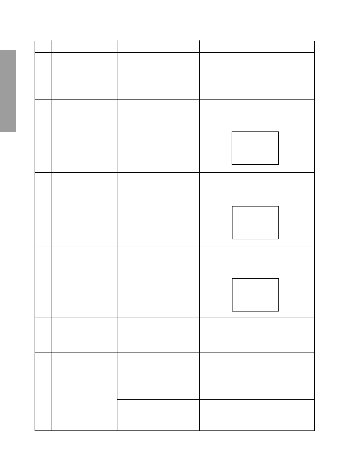
Connect a 1500 ohm 10 watt resistor, paralleled b y a 0.15
µF, AC type capacitor, between a known good earth ground
(water pipe, conduit, etc.) and the exposed metallic parts,
one at a time. Measure the AC voltage across the combination of 1500 ohm resistor and 0.15 µF capacitor. Reverse the AC plug at the AC outlet and repeat AC voltage
measurements for each exposed metallic part. Voltage
measured must not exceed 0.3 v olts rms. This corresponds
to 0.2 milliamp. AC. Any value exceeding this limit constitutes a potential shock hazard and must be corrected immediately.
AC VOLTMETER
0.15µF
Place this probe on
Good earth ground
such as a water
pipe, conduit, etc.
1500 ohm
10 watt
each exposed
metallic part.
SPECIFIC INFORMATIONS
PRODUCT SAFETY NOTICE
Many electrical and mechanical parts in this chassis have special safety-related characteristics. These characteristics are
often passed unnoticed by a visual inspection and the protection afforded by them cannot necessarily be obtained b y using
replacement components rated for higher voltage, wattage, etc. Replacement parts which have these special safety characteristics are identified in this manual and its supplements; electrical components having such features are identified by
the international hazard symbols on the schematic diagram and the parts list.
Before replacing any of these components, read the parts list in this manual carefully. The use of substitute replacement
parts which do not have the same safety characteristics as specified in the parts list may create shock, fire, X-ray
radiation or other hazards.
– 3 –
WARNING: BEFORE SERVICING THIS CHASSIS, READ THE “X-RAY RADIATION PRECAUTION”, “SAFETY PRECAU-
TION” AND “PRODUCT SAFETY NOTICE” ON PAGE 3 OF THIS MANUAL.
■ The following adjustments should be made when a complete realignment is required or a new picture tube is installed.
Perform the adjustments in order as follows :
1. Color Purity
2. Convergence
3. White Balance
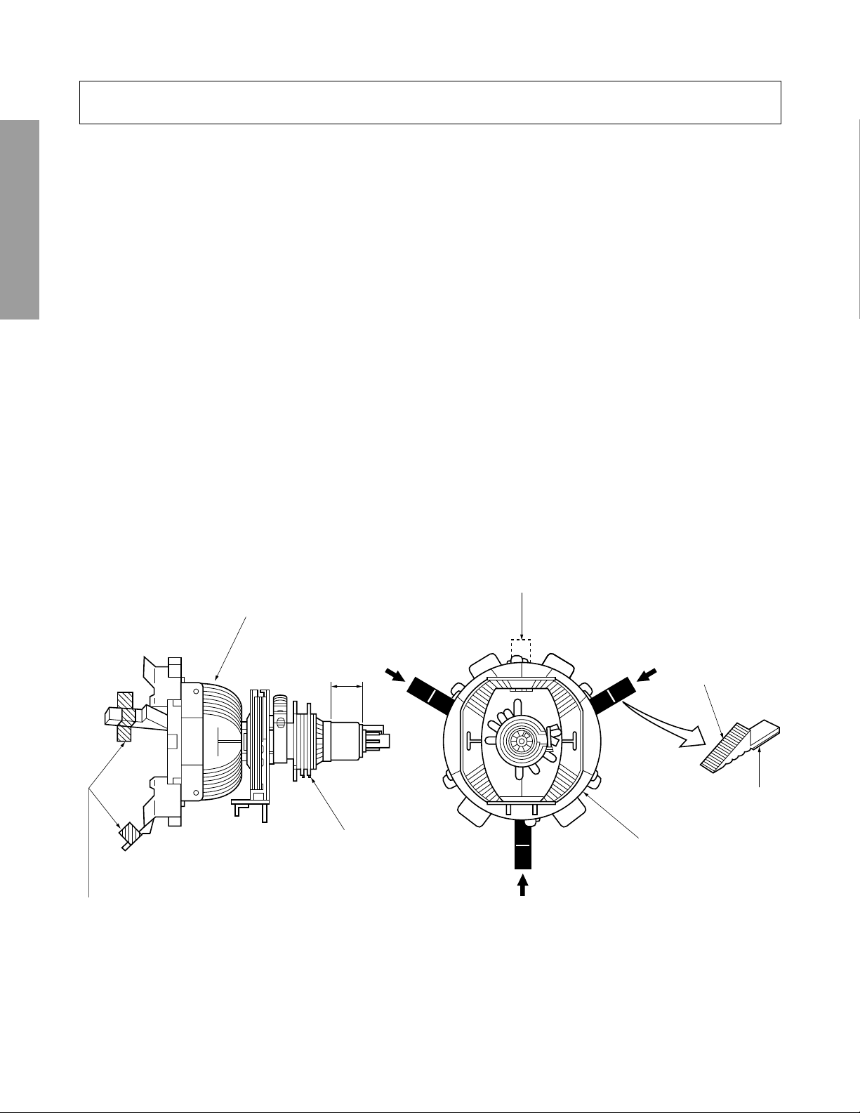
Note: The PURITY/CONVERGENCE MAGNET assembly and rubber wedges need mechanical positioning.
Refer to figure 1.
GENERAL ADJUSTMENTS
*
COLOR PURITY ADJUSTMENT
NOTE : Before attempting any purity adjustments, the receiver
1. Demagnetize the picture tube and cabinet using a degauss-
2. Set the brightness and contrast to maximum.
3. Use a green raster from among the built-in test signals.
4. Loosen the clamp screw holding the yoke and slide the
SPECIFIC INFORMATIONS
Mounting position of the purity magnet assembly should fit to same position as old one because slightly difference to
the position depend on a kind of tube.
There are no adjustment of purity and convergence in some picture tube (Unified with purity magnet)
should be operated for at least fifteen minutes.
ing coil.
yoke backward or forward to provide vertical green belt
(zone) in the picture screen.
SET-UP ADJUSTMENT (FOR 13”, 14”, 19”, 20”)
5. Remove the Rubber Wedges.
6. Rotate and spread the tabs of the purity magnet (See figure 2.) around the neck of the picture tube until the green
belt is in the center of the screen. At the same time , enter
the raster vertically.
7. Slowly move the yoke forward or backward until a uniform
green screen is obtained. Tighten the clamp screw of the
yoke temporarily.
8. Check the purity of the red and blue raster.
GLASS CLOTH
TAPES
DEFLECTION
YOKE
14mm(13", 14")
19mm(19", 20")
PURITY/
CONVERGENCE
MAGNET ASS'Y
TEMPORARY
MOUNTING
RUBBER WEDGE
ADHESIVE
DEFLECTION
YOKE
Figure 1.
– 4 –
CONVERGENCE ADJUSTMENTS
NOTE: Before attempting any convergence adjustments, the
receiver should be operated for at least fifteen minutes.
■ CENTER CONVERGENCE ADJUSTMENT
1. Use the cross-dot pattern from among the built-in test signals.
2. Set the brightness and contrast for well defined pattern.
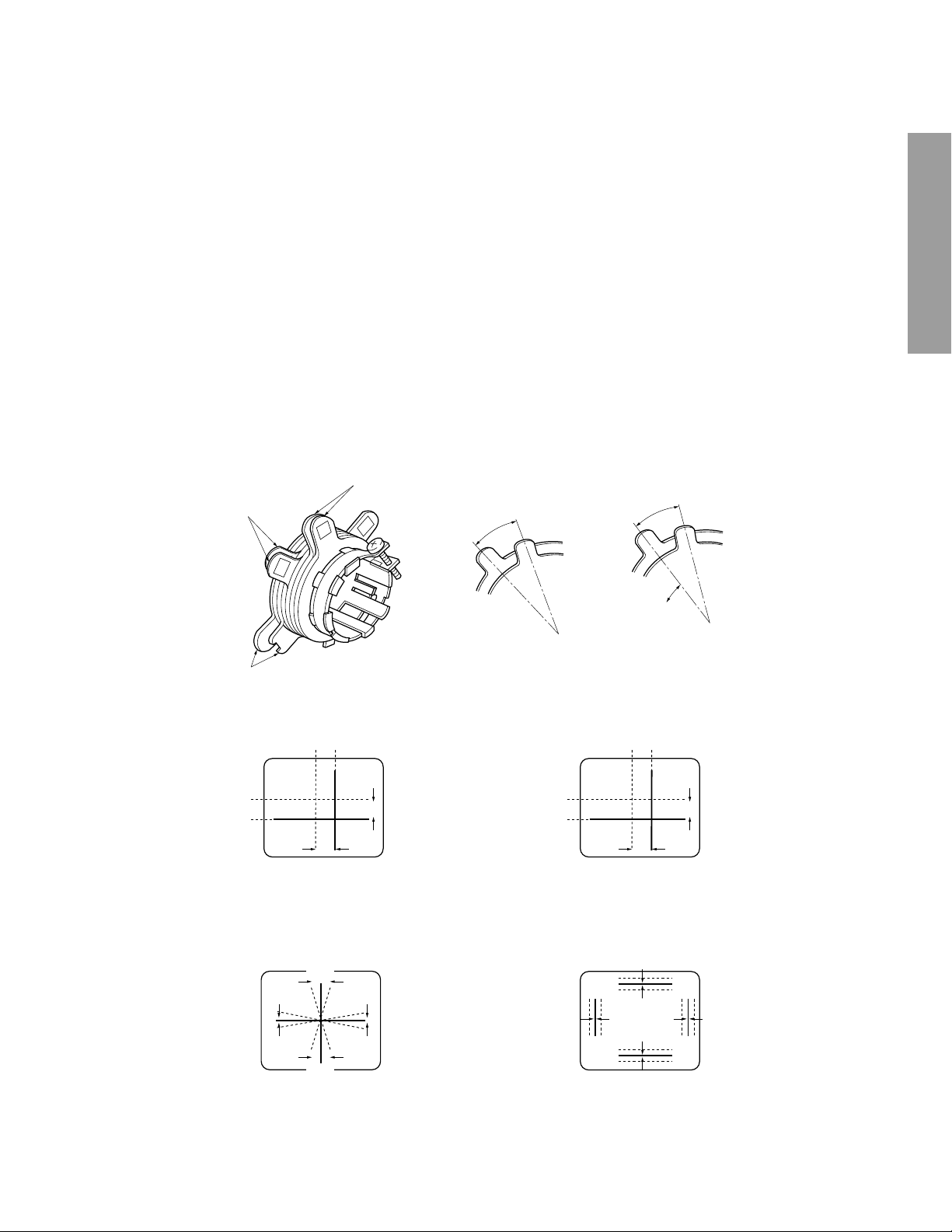
3. Adjust two tabs of the 4-Pole Magnets to change the angle between them (See figure 2.) and superimpose red
and blue vertical lines in the center area of the picture
screen.
4. Turn the both tabs at the same time keeping the angle
constant to superimpose red and blue horizontal lines at
the center of the screen.
5. Adjust two tabs of 6-Pole Magnets to superimpose red/
blue line and green one. Adjusting the angle affects the
vertical lines and rotating both magnets affects the horizontal lines.
6. Repeat adjustments 3, 4, 5 keeping in mind red, green
and blue movement, because 4-Pole Magnets and 6-Pole
Magnets have mutual interaction and make dot movement
complex.
4-POLE
MAGNETS
6-POLE
MAGNETS
ADJUST THE ANGLE
(VERTICAL LINES)
■ CIRCUMFERENCE CONVERGENCE ADJUSTMENT
1. Loosen the clamping screw of deflection yoke slightly to
allow the yoke to tilt.
2. Temporarily put a wedge as shown in figure 1. (Do not
remove cover paper on adhesive part of the wedge.)
3. Tilt front of the deflection yoke up or down to obtain better
convergence in circumference. (See figure 3.) Push the
mounted wedge into the space between picture tube and
the yoke to fix the yoke temporarily.
4. Put other wedge into bottom space and remove the cover
paper to stick.
5. Tilt front of the yoke right or left to obtain better convergence in circumference. (See figure 3.)
6. Keep the yoke position and put another wedge in either
upper space. Remove cover paper and stick the wedge
on picture tube to fix the yoke.
7. Detach the temporarily mounted wedge and put it in another upper space. Stick it on picture tube to fix the yoke.
8. After fixing three wedges, recheck overall convergence.
Tighten the screw firmly to fix the yoke and check the y oke
is firm.
9. Stick three adhesive tapes on wedges as shown in figure
1.
FIXED
GENERAL ADJUSTMENTS
ROTATE TWO TABS
AT THE SAME TIME
(HORIZONTAL LINES)
PURITY
MAGNETS
CONVERGENCE MAGNET ASSEMBLY ADJUSTMENT OF MAGNETS
Figure 2.
BLU RED
BLU
RED
4-POLE MAGNETS MOVEMENT
BGR
R
G
B
RGB
RED/BLU
GRN
Center Convergence by Convergence Magnets
B
G
R
RED/BLU GRN
6-POLE MAGNETS MOVEMENT
B
G
R
BGR
RGB
R
G
B
SPECIFIC INFORMATIONS
INCLINE THE YOKE UP (OR DOWN)
Circumference Convergence by DEF Yoke
Figure 3. Dot Movement Pattern
INCLINE THE YOKE RIGHT (OR LEFT)
– 5 –

WARNING: BEFORE SERVICING THIS CHASSIS, READ THE “X-RAY RADIATION PRECAUTION”, “SAFETY PRECAU-
TION” AND “PRODUCT SAFETY NOTICE” ON PAGE 3 OF THIS MANUAL.
■ The following adjustments should be made when a complete realignment is required or a new picture tube is installed.
Perform the adjustments in order as follows :
1. Color Purity
2. Convergence
3. White Balance
Note: The PURITY/CONVERGENCE MAGNET assembly and rubber wedges need mechanical positioning.
Refer to figure 1.
GENERAL ADJUSTMENTS
*
Mounting position of the purity magnet assembly should fit to same position as old one because slightly difference to
the position depend on a kind of tube.
There are no adjustment of purity and convergence in some picture tube (Unified with purity magnet)
(FOR 35”, 36”)
COLOR PURITY ADJUSTMENT
NOTE : Before attempting any purity adjustments, the
receiver should be operated for at least fifteen
minutes.
1. Evenly degauss the entire screen.
2. Set the CONTRAST and BRIGHTNESS Controls to
the maximum.
3. Display built-in green raster using the TEST SIGNAL
SELECTION function.
4. Loosen the clamp screw holding the deflection yoke
SPECIFIC INFORMATIONS
(and remove the Rubber Wedges).
5. Slide the yoke forward or backward to provide vertical
green belt (zone) in the picture screen.
6. Rotate and spread the tabs of the purity magnet (See
figure 3.) around the neck of the picture tube until the
green belt is in the center of the screen. At the same
time, center the raster vertically by adjusting the magnet as shown below.
Figure 1.
Xv Coil
DEFLECTION YOKE
1-5/8”
PURITY/
CONV.
MAGNET
RUBBER WEDGES
Adhesive
Green Belt
7. Move the yoke slowly forward or backward until a uniform green screen is obtained. Tighten the clamp scre w
of the yoke temporarily.
8. Check the purity of the red and blue raster.
9. Put four wedges into the space between the picture
tube and the yoke to hold the yoke in the adjusted
position. (See figure 2.)
Do not tilt the yoke by excessive insertion of the wedge.
10. Remove cover paper of wedge and stick wedges on
the tube to fix the yoke in the adjusted position.
Fix the wedges with glass cloth tapes.
DEFLECTION
YOKE
Figure 2.
– 6 –

CONVERGENCE ADJUSTMENTS
NOTE: Before attempting any convergence adjustments,
the receiver should be operated for at least fifteen
minutes.
■ CENTER CONVERGENCE ADJUSTMENT
1. Display built-in cross-dot pattern using the TEST SIGNAL SELECTION function.
2. Adjust the BRIGHTNESS and CONTRAST Controls
for well defined pattern.
3. Loosen the tightening ring and adjust two tabs of the
4-Pole Magnets to change the angle between them
(See figure 3.) and superimpose red and blue vertical
lines in the center area of the picture screen.
(See figure 4.)
4. Turn the both tabs at the same time keeping the constant angle to superimpose red and blue horizontal
lines at the centre of the screen. (See figure 4.)
5. Adjust two tabs of 6-Pole Magnets to superimpose red/
blue line with green one. Adjusting the angle affects
the vertical lines and rotating both magnets affects the
horizontal lines.
6. Repeat adjustments 3, 4, 5 keeping in mind red, green
and blue movement, because 4-Pole Magnets and 6Pole magnets interact and make dot movement complex.
7. After completing the “CENTER CONVERGENCE ADJUSTMENT” tighten the tightening ring to fix the magnets.
BLU RED
RED/BLUE GRN
6-POLE
MAGNETS
PURITY
MAGNETS
ADJUST THE ANGLE
(VERTICAL LINES)
ADJUSTMENT OF MAGNETS
4-POLE
MAGNETS
PURITY/CONVERGENCE
MAGNETS
FIXED
ROTATE TWO TABS
AT THE SAME TIME
(HORIZONTAL LINES)
GENERAL ADJUSTMENTS
SPECIFIC INFORMATIONS
BLU
RED
4-POLE MAGNETS
MOVEMENT
Center Convergence by Convergence Magnets
■ Xv COIL ADJUSTMENT
Adjust the Xv coil (on the deflection yoke) to correct
misconvergence at both sides on screen.
Use a hexagonal tip stick (plastic) to adjust the core of
coil.
Clockwise Adjustment Counterclockwise Adjustment
Clockwise Adjustment
R
B
RED/BLUE
Figure 4.
B
R
GRN
6-POLE MAGNETS
MOVEMENT
Counterclockwise Adjustment
B
R
Figure 3.
■ SCREEN-CORNER CONVERGENCE
When the misconvergence is still evident on corners even
though the above adjustment is done, use the ferrite sheet
(Part No. 23993622) to correct misconvergence.
1. Put ferrite sheets into the space under the yoke.
Decide such position that misconvergence becomes
minimum, watching picture screen. (See figure below .)
2. Remove cover paper of ferrite sheet to stick it in the
place on the tube. Put adhesive tapes on ferrite sheets
to fix.
Ferrite
Sheets
R
B
A
Ferrite
Sheets
XV Cross Pattern View
Xv Cross Pattern View
For correcting misconvergence
on the position A
– 7 –
1. ENTERING TO SERVICE MODE
1) Press MUTE button once
on Remote Control.
MUTE
SERVICE MODE
2) Press MUTE button
again to keep pressing.
3) While pressing the MUTE button,
press MENU button on TV set.
S
(Service mode display)
GENERAL ADJUSTMENTS
2. DISPLAYING THE ADJUSTMENT MENU
1) Press MENU button on TV.
Service mode
3. KEY FUNCTION IN THE SERVICE MODE
The following key entry during display of adjustment menu provides special functions.
SPECIFIC INFORMATIONS
A single horizontal line ON/OFF: TV (ANT)/VIDEO button (on TV)
Test signal selection : TV (ANT)/VIDEO button (on Remote)
Selection of the adjustment items : Channel s/t (on TV or Remote)
Change of the data value : Volume s/t (on TV or Remote)
Adjustment menu mode ON/OFF : MENU button (on TV)
Initialization of the memory (QA02) : RECALL+Channel button on TV (s)
Initialization of the self diagnostic data: RECALL+Channel button on TV (t)
“RCUT” selection : 1 button
“GCUT” selection : 2 button
“BCUT” selection : 3 button
“CNTX” selection : 4 button
“COLC” selection : 5 button
“TNTC” selection : 6 button
Test audio signal ON/OFF (1kHz) : 8 button
Self diagnostic display ON/OFF : 9 button
Adjustment mode
S
Press
Press
Item
Data
– 8 –

4. SELECTING THE ADJUSTING ITEMS
1) Every pressing of CHANNEL s button in the service mode changes the adjustment items in the order of table-2.
(t button for reverse order)
Refer to table-2 for preset data of adjustment mode.
(See SETTING & ADJUSTING DATA on page 17)
5. ADJUSTING THE DATA
1) Pressing of VOLUME s or t button will change the value of data in the range from 00H to FFH. The variable range
depends on the adjusting item.
6. EXIT FROM SERVICE MODE
1) Pressing POWER button to turn off the TV once.
■ INITIALIZATION OF MEMORY DATA OF QA02
After replacing QA02, the following initialization is required.
1. Enter the service mode, then select any register item.
2. Press and hold the RECALL button on the Remote, then press the CHANNEL s button on the TV. The initialization of QA02
has been complated.
3. Check the picture carefully. If necessary, adjust any adjustment item above.
Perform “Programming Channel Memory” on the owner’s manual.
CAUTION: Never attempt to initialize the data unless QA02 has been replaced.
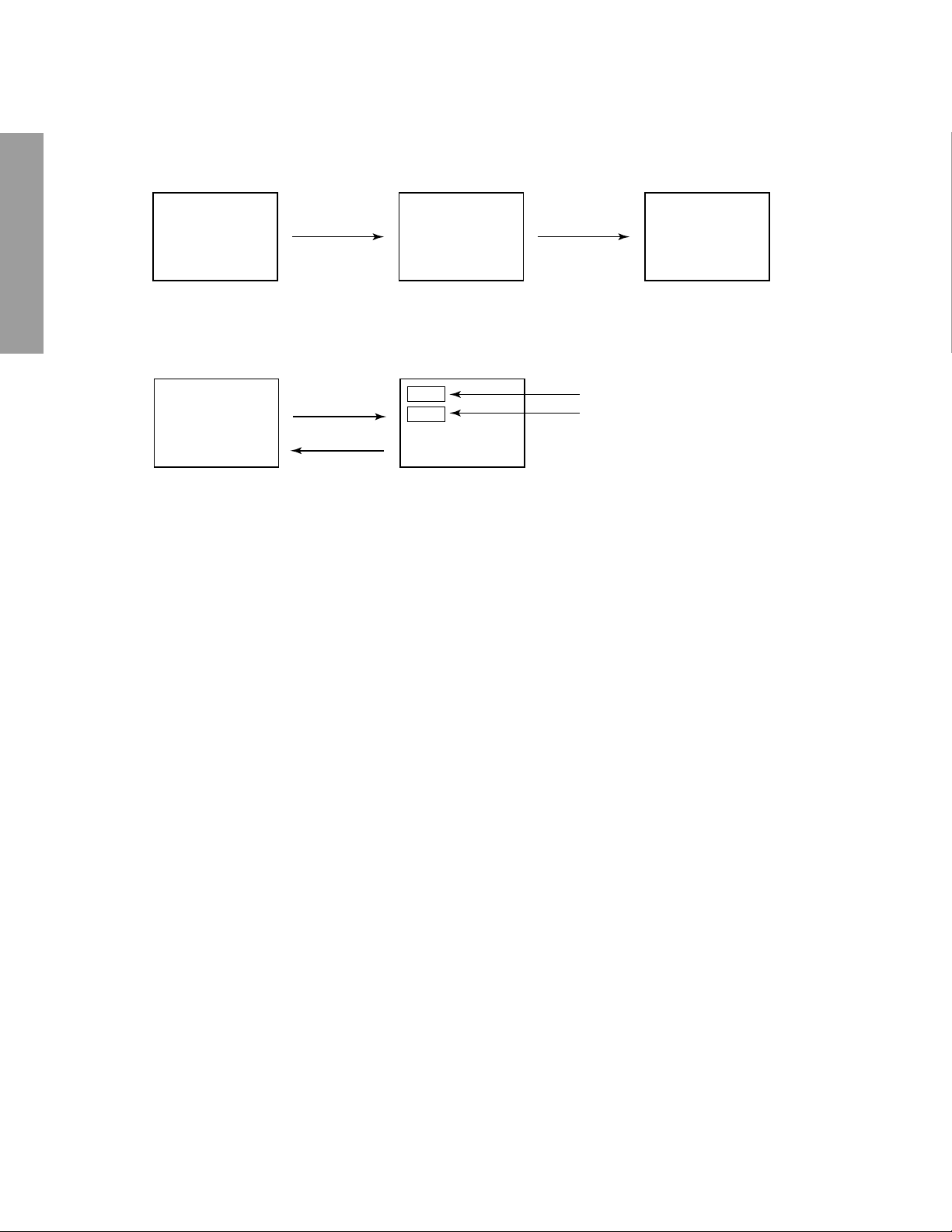
7. TEST SIGNAL SELECTION
1) Every pressing of TV/VIDEO button on the Remote Control in the Service mode, changes the built-in test patterns
on screen in the following order.
GENERAL ADJUSTMENTS
Normal picture Black cross-bar
on green raster
Red raster
Green raster
Blue raster
All black
All white
White and black
Black cross-bar
White cross-bar
2) Press “8” button while any built-in test pattern to on the screen to
output the 1 kHz sound. Press the button again to cut off the sound.
Note: If the video cable is connected to the VIDEO1 INPUT jack, the
built-in pattern signals are not displayed.
H signal (black)
H signal (white)
White cross-dot
Black cross-dot
White cross-hatch
Black cross-hatch
Signals Picture
• Red raster
• Green raster
• Blue raster
• All Black
• All White
• Black & White
• Black cross-bar
• White cross-bar
• Black cross-bar
on green raster
• Black cross-hatch
• White cross-hatch
• Black cross-dot
• White cross-dot
SPECIFIC INFORMATIONS
• H signal (white)
• H signal (black)
The signals marked with are not usable to display in the Test signal for some model.
*
– 9 –

8. SELF DIAGNOSTIC FUNCTION
1) Press “9” button on Remote Control during display of adjustment menu in the service mode.
The diagnosis will begin to check if interface among IC’s are executed properly.
2) During diagnosis, the following displays are shown.
SELF CHECK
NO. 23
POWER : 000
BUS LINE : OK
BUS CONT : OK
BLOCK : UV V1 V2
or QV01 QV01S
SYNC
GENERAL ADJUSTMENTS
Part number of microprocessor (QA01)
Operation number of protection circuit (current limiter) . . . . “000” is normal.
BUS line check “OK” ................... Normal
BUS line ACK (acknowledge) check
SPECIFIC INFORMATIONS
Sync. signal check Green display..... Normal
******
“SCL-GND” ........ SCL-GND short circuit
“SDA-GND”........ SDA-GND short circuit
“SCL-SDA”......... SCL-SDA short circuit
“OK” ..................... Normal
Display of Location Number . . . . NG
(Display example)
“QA02 NG”, “H001 NG”, “Q501 NG” etc.
Note: The indication of failure place is only one place though failure places are plural. When
repair of a failure place finishes, the next failure place is indicated. (The order of priority of
indication is left side.)
Cyan display ......No check
Red display ........ NG
UV........... TV mode
V1 ........... VIDEO 1 mode
V2 ........... VIDEO 2 mode
The item marked with are not usable to display in the SELF DIAGNOSTIC FUNCTION for some model.
*
– 10 –

1. ENTERING TO DESIGN MODE
1) Select the Service mode.
DESIGN MODE
2) While pressing RECALL button on
Remote and press MENU button on TV.
3) Press MENU button on TV.
S D
(Design mode) (Adjustment mode)
When QA02 is initialized, items “OPT0” and “OPT1” of DESIGN MODE are set to the data of the representative model of this
chassis family.
Therefore, because ON-SCREEN specification remains in the state of the representative of model. This model is required to
reset the data of items “OPT0” and “OPT1”.
2. SELECTING THE ADJUSTING ITEMS
Every pressing of CHANNEL t button in the design mode changes the adjustment items in the order of table-3.
(s button for reverse order)
Refer to table-3 for data of design mode.
(See SETTING & ADJUSTING DATA on page 17)
3. ADJUSTING THE DATA
Pressing of VOLUME s or t button will change the value of data.
Press
Press
Item
Data
GENERAL ADJUSTMENTS
SPECIFIC INFORMATIONS
– 11 –
ELECTRICAL ADJUSTMENT
ITEM ADJUSTMENT PROCEDURE
FOCUS VR ADJ
SUB-BRIGHTNESS
(BRTC)
GENERAL ADJUSTMENTS
SUB-COLOR
(COLC)
SUB-TINT
(TNTC)
SPECIFIC INFORMATIONS
1. Enter the service mode, then select any register item.
2. Press the TV/VIDEO button on the Remote until the black cross-bar pattern appears on the screen.
3. Adjust the FOCUS control (on T461) for well defined scanning lines on the picture
screen.
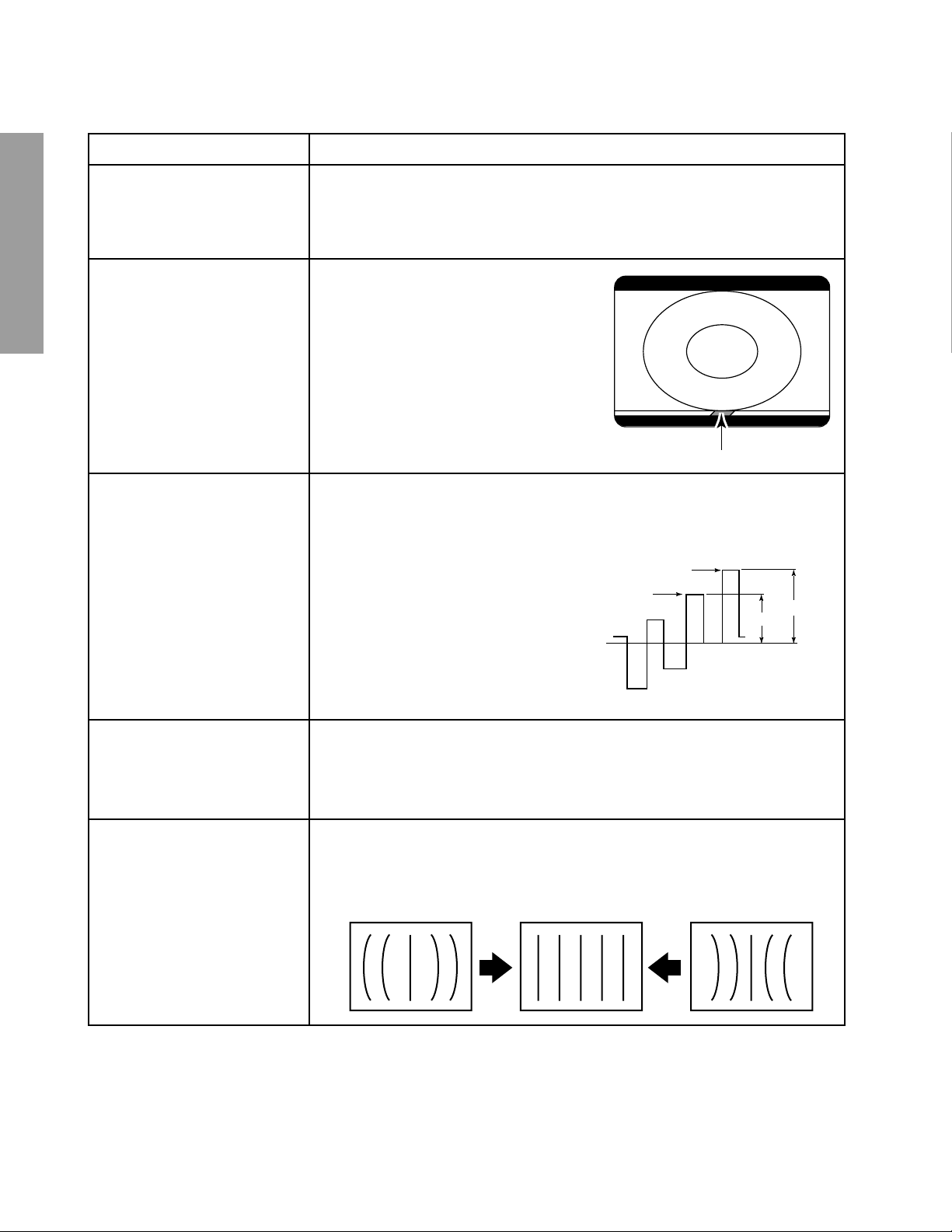
1. Constrict the picture height until the
vertical retrace line appears adjusting
the HEIGHT control on the MAIN board.
2. Adjust the CONTRAST to the minimum
and BRIGHTNESS to the center.
3. Enter the service mode, then select
“BRTC” register.
4. Adjust the data value so the belt of
vertical retrace line just disappear.
5. Adjust the CONTRAST for the desired
contrast.
6. Adjust the HEIGHT control.
Vertical retrace line
1. Receive color-bar signal from color-bar generator.
2. Press the RESET button.
3. Connect oscilloscope to base of Q906 on CRT-D board.
4. Enter the service mode, then select “COLC”.
5. Adjust the SUB-COLOR by pressing the
VOLUME s or t button to achieve about
1V0-p of blue bar.
6. Select “TNTC” register.
7. Adjust the data value to obtain the blue
bar to magenta bar ratio of 3:2 as shown.
Magenta
0
Blue
2
3 (1.8V
8. Select “COLC” register.
9. Adjust the data value to achieve 1.8V0-p
of blue bar on scope.
10. Check the picture with off-air signal.
0-P
)
WIDTH
(WID)
E-W PARABOLA
(DPC)
1. Call up the adjustment mode display, then select the item WID.
2. Press the VOLUME s or t button to get the picture so the left and right edges of
raster begins to lack.
3. Press the VOLUME s or t button to advance the data by 7 steps.
Note : Check the horizontal picture position is correct.
1. Call up the adjustment mode display, then select the item DPC.
2. Press the TV/VIDEO button on Remote until the cross-hatch pattern appears on
the screen.
3. Press the VOLUME s or t button to make vertical lines straight as shown
below.
– 12 –

ITEM ADJUSTMENT PROCEDURE
HORIZONTAL POSITION
(HPOS)
VERTICAL POSITION
(VPOS)
HEIGHT
(HIT)
WHITE BALANCE
(RCUT)
(GCUT)
(BCUT)
(GDRV)
(BDRV)
1. Call up the adjustment mode display, then select the item HPOS or VPOS.
2. Press the TV/VIDEO button on Remote until the
white cross-bar or black cross-bar pattern appears
on the screen.
3. Adjust the HORIZONTAL and VERTICAL position
alternately by pressing the VOLUME s or t button
for proper picture position.
4. Check the picture with off-air signal.
1. Call up the adjustment mode display, then select the item HIT.
2. Press the VOLUME s or t button to get the picture so the top of raster begins
to lack.
3. Press the VOLUME s button to advance the data by 9 steps.
Note : Check the vertical picture position is correct.
1. Adjust the CONTRAST control to the center, and BRIGHTNESS control to the
maximum.
2. Call up the adjustment mode display, and press the TV/VIDEO button on
Remote until the white and black pattern appears on the screen.
3. Adjust the following item with the CHANNEL s/t and VOLUME s/t buttons.
RCUT
GCUT
BCUT
4. Press the TV/VIDEO button on TV to display a single horizontal line on the
screen.
5. Turn the SCREEN control (FBT) fully counterclockwise and gradually rotate
clockwise until the first horizontal line appears slightly on the screen.
6. Press the TV/VIDEO button to display the normal picture.
7. Adjust the remaining two “?CUT” items (CHANNEL s/t → TV/VIDEO →
VOLUME s/t in order) to obtain the slightly lighted horizontal line in the same
levels of three (red, green, blue) colors. The line should be white if the adjustments are proper.
Data : 40H
Data : 40H
Data : 40H
GDRV Data : 40H
BDRV Data : 40H
GENERAL ADJUSTMENTS
SPECIFIC INFORMATIONS
PIP SUB-BRIGHTNESS
(PBOF)
PIP WHITE BALANCE
(PGOF, PROF)
PIP SUB-TINT
(PHUE)
Bright area
Adjust "GDRV" or "BDRV" to be white.
Dark area
Fine adjust "RCUT", "GCUT" or "BCUT" to be black.
Adjust to match the PIP screen to the brightness, white balance and tint of the
main picture.
– 13 –
MTS ADJUSTMENT (FOR N1F CHASSIS)
No. ITEM INPUT SIGNAL ADJUSTMENT PROCEDURE
STEREO VCO
1
(STVC)
SAP VCO
2
(SAVC)
GENERAL ADJUSTMENTS
STEREO FILTER
3
(STRF)
• No signal 1. Display item STVC, and connect pin 9 of
H002 to ground.
2. Connect frequency counter to pin 12 of
H002.
3. Change data by Volume s/t buttons so
that the reading of counter becomes value
as close as 4fH (62.936kHz).
• 78.670kHz 147mVrms
→ pin 9 of H002
• Monaural signal → ANT
1. Display item SAVC.
2. Change data by Volume s/t buttons so
that the data becomes in the center of
range for STA7=0 and STA8=1.
SAVC
88H
STA7:0 STA8:1
• 9.4kHz 600mVrm
→ pin 9 of H002
Monaural signal → ANT
1. Display item STRF on screen.
2. Change data by Volume s/t buttons so
that the data becomes in the center of
range for STA3=1.
SPECIFIC INFORMATIONS
SAP FILTER
4
(SAPF)
ATTENUATOR
5
(ATT)
STEREO SEPARATION
6
(WBAN)
• 88kHz 110mVrms
→ pin 9 of H002
• Monaural signal → ANT
• 1kHz 30% mod. → ANT
terminal
• STEREO 300Hz R-channel
only → ANT
STRF
16H
STA3:1
1. Display item SAPF.
2. Change data by Volume s/t buttons so
that the data becomes in the center of
range for STA4=1.
SAPF
98H
STA4:1
1. Connect rms meter to pin 12 of H002.
2. Display item AT T on screen.
3. Change data by Volume s/t buttons so
that output at pin 12 of H002 becomes
value as close as 130mVrms.
1. Select “STEREO” mode from the MTS
function in the Audio menu.
2. Display item WBAN on screen.
3. Connect oscilloscope to pin 14 of H002.
4. Change data by Volume s/t buttons so
that 300Hz element on scope becomes
minimum.
(SPEC)
• STEREO 3kHz R-channel
only → ANT
– 14 –
5. Display item SPEC on screen.
6. Change data by Volume s/t buttons so
that 3kHz element on scope becomes
minimum.
MTS ADJUSTMENT (FOR N0ES CHASSIS)
No. ITEM INPUT SIGNAL ADJUSTMENT PROCEDURE
1
ATTENUATOR
(ATT)
• 1kHz 30% mod. → ANT
terminal
1. Connect rms meter to pin 34 of QG01.
2. Display item ATT on screen.
3. Change data by VOLUME s/t buttons so
that the reading of meter becomes value
as close as 137mVrms.
2
STEREO VCO
(STVC)
• No signal 1. Short circuit RG44 with a jumper wire.
2. Display item STVC on screen.
3. Connect frequency counter to pin 34 of
QG01.
4. Change data by VOLUME s/t buttons so
that the reading of counter becomes value
as close as 15.73kHz.
3
STEREO FILTER
(STRF)
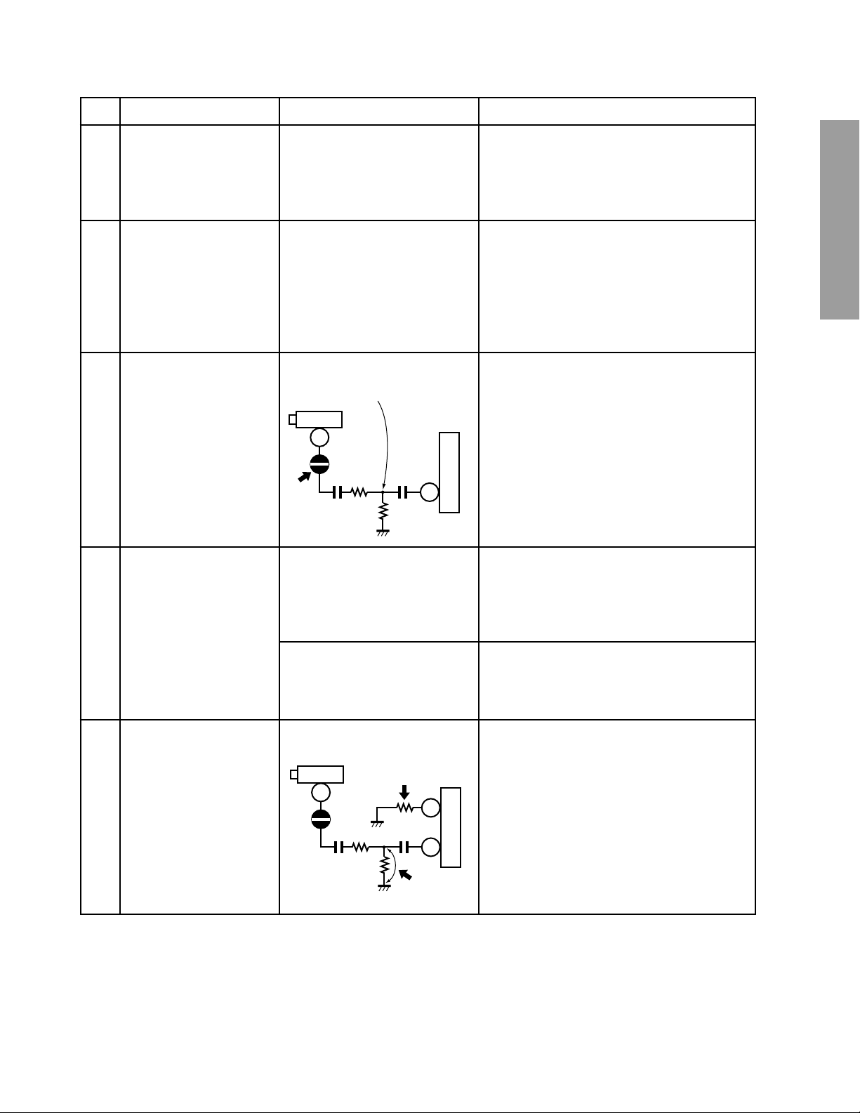
• 15.734kHz 30mV(rms) 1. Unsolder the solder link SL02.
2. Display item STRF on screen.
15.734KHz 30mV(rms)
H001
10
SL02
+
1
RG43
CG44
CG07
RG44
+
QG01
7
3. Connect oscilloscope to pin 34 of QG01.
4. Change data by VOLUME s/t button to
minimize AC output level on scope.
5. Resolder SL02.
GENERAL ADJUSTMENTS
SPECIFIC INFORMATIONS
STEREO SEPARATION
4
(WBAN)
(SPEC)
SAP VCO
5
(SAVC)
• STEREO 300Hz R-channel
only → ANT
1. Display item WBAN on screen.
2. Connect oscilloscope to pin 35 of QG01.
3. Change data by VOLUME s/t buttons so
that 300Hz element on scope becomes
minimum.
• STEREO 3kHz R-channel
only → ANT
4. Display item SPEC on screen.
5. Change data by Volume s/t buttons so
that 3kHz element on scope becomes
minimum.
• No signal 1. Shortcircuit RG44 with a short jumper.
2. Connect 1Mohm resistor between pin 12 of
H001
2
QG01
10
12
1M
++
CG44 RG43
RG44
7
1
QG01 and ground.
3. Display item SAVC on screen.
4. Connect frequency counter to pin 34 of
QG01.
5. Change data by VOLUME s/t buttons so
that the reading of counter becomes value
as close as 78.67kHz.
6. Remove the short jumper and 1M ohm
resistor.
– 15 –
CIRCUIT CHECKS
HIGH VOLTAGE CHECK
CAUTION: There is no HIGH VOLTAGE ADJUSTMENT on
this chassis. Checking should be done following the steps
below.
1. Connect an accurate high voltage meter to the second anode of the picture tube.
2. Tur n on the receiver. Set the BRIGHTNESS and CONTRAST controls to minimum (zero beam current).
3. High voltage must be measured below (B) kV.
Refer to table-1 for high voltage (B).
(See SETTING & ADJUSTING DATA on page 17)
GENERAL ADJUSTMENTS
SPECIFIC INFORMATIONS
4. Vary the BRIGHTNESS control to both extremes to be sure
the high voltage does not exceed the limit under any conditions.
FS CIRCUIT CHECK
The Fail Safe (FS) circuit check is indispensable for the final
check in servicing. Checking should be done following the
steps below.
1. Turn the receiver on and press the RESET button.
2. Temporarily short TP-(R) and TP-(X) with a jumper wire.
Raster and sound will disappear.
3. The receiver must remain in this state even after removing
the jumper wire. This is the evidence that the FS circuit is
functioning properly.
4. To obtain a picture again, temporarily turn the receiver off
and allow the FS circuit more than 5 seconds to reset.
Then turn the power switch on to produce a normal picture.
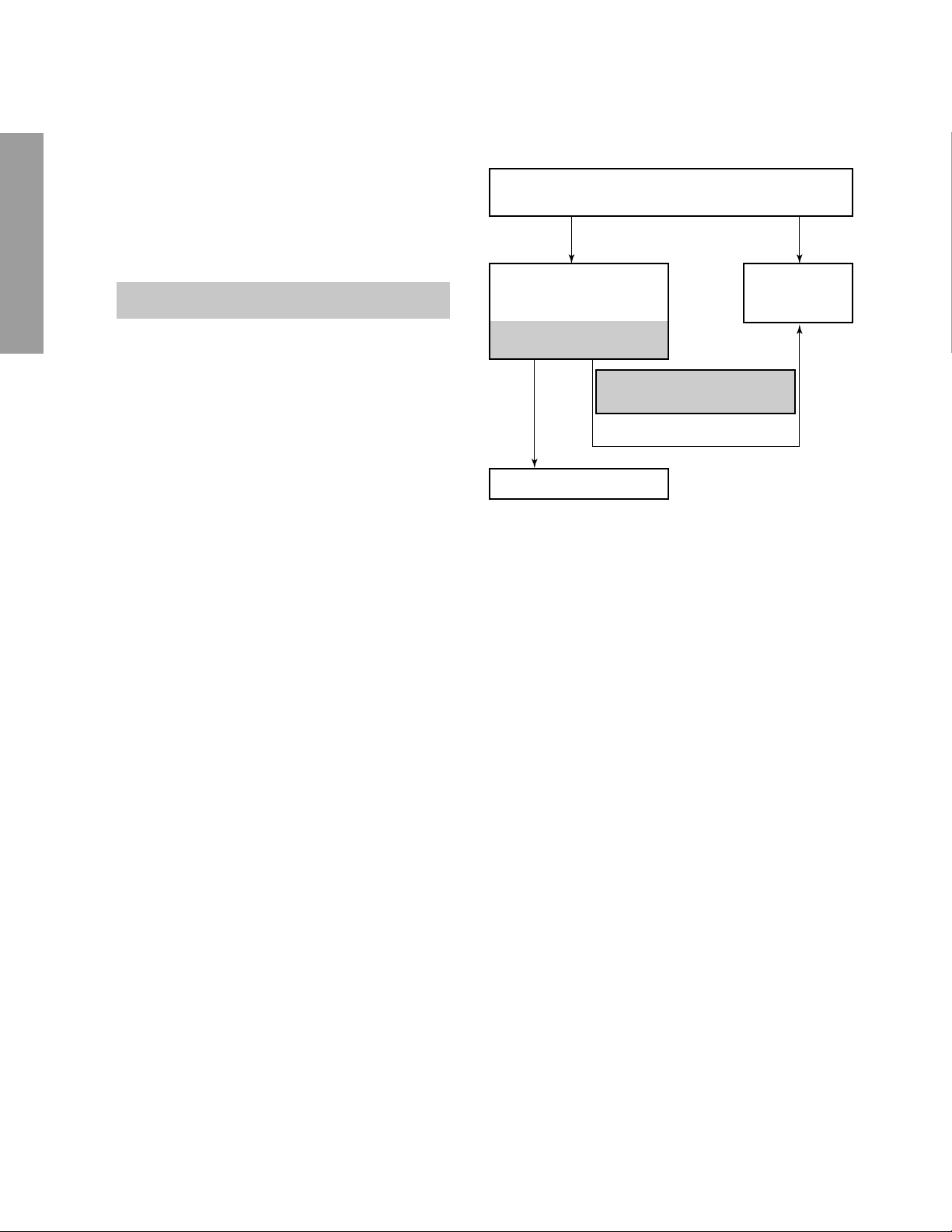
Troubleshooting Guide for Fail Safe Circuit
Check that the set returns to normal operation when pin 12
of Z801(or emitter of Q472) is grounded with jumper wire.
YES NO
Check the voltage across
Capacitor C471 is
approximately (C) volts.
Refer to table –4 for
fail safe voltage (C) .
YES
Defective Fail Safe Circuit
(See SETTING & ADJUSTING
DATA on page17)
NO
Faulty power
circuit or horizontal circuit.
– 16 –

CHAPTER 2 SPECIFIC INFORMATIONS
SETTING & ADJUSTING DATA
SAFETY INSTRUCTIONS
HIGH VOLTAGE AT ZERO BEAM: (A) 31.0kV
MAX HIGH VOLTAGE:
Table-1
SERVICE MODE
32"
(B) 32.4 kV
ADJUSTING ITEMS AND DATAS IN THE SERVICE MODE:
Item Name of adjustment Preset
RCUT
GCUT
BCUT
GDRV
BDRV
SCNT
BRTC
COLC
TNTC
SAVC
ATT
SAPF
STVC
STRF
SPEC
WBAN
HPOS
VPOS
R CUTOFF
G CUTOFF
B CUTOFF
G DRIVE
B DRIVE
SUB-CONTRAST
SUB-BRIGHT
SUB-COLOR
SUB-TINT
SAP VCO
ATTENUATOR
SAP FILTER
STEREO VCO
STEREO FILTER
SPECTRAL
STEREO SEPARATION
HORIZ. POSITION
VERT. POSITION
40H
40H
40H
40H
40H
0AH
40H
3AH
44H
20H
20H
88H
20H
20H
20H
20H
16H
03H
32"
←
←
←
←
←
←
←
←
←
←
←
←
←
←
←
←
←
←
Item Name of adjustment Preset
HIT
LIN
VSC
VPS
VCP
WID
DPC
CNR
TRAP
HCP
VFC
PCOL
PHUE
PGOF
PROF
PBOF
RGBB
HEIGHT
V-LINEARITY
V-S CORRECTION
V-SHIFT
V-COMPENSATION
PICTURE WIDTH
E-W PARABOLA (DPC)
E-W CORNER
TRAPEZIUM
H-COMPENSATION
V-F CORRECTION
PIP COLOR
PIP TINT
PIP
PIP
PIP
RGB BRIGHT
26H
07H
02H
01H
03H
35H
17H
09H
08H
00H
0FH
0FH
11H
36H
17H
17H
0BH
32"
←
←
←
←
←
←
←
←
←
←
←
←
←
←
←
←
←
GENERAL ADJUSTMENTS
SPECIFIC INFORMATIONS
Table-2
DESIGN MODE
ADJUSTING ITEMS AND DATAS IN THE DESIGN MODE:
Item Name of adjustment Preset Data
OPT1 OPTION1 84H 84H
OPT2 OPTION2 01H 01H
Table-3
CIRCUIT CHECKS
FBT DETECTION VOLTAGE (C) 21.88 V
Table-4
– 17 –
Data
32"
Remarks
32"

GENERAL ADJUSTMENTS
LOCATION OF CONTROLS
Front view Rear view
SPECIFIC INFORMATIONS
VIDEO-3 IN
VIDEO
VIDEO/AUDIO
terminals
AUDIO
L/MONO R
INSIDE DOOR
DEMO
DEMO
MENU VOLUME CHANNEL
TV/VIDEO
MENU
VOLUME T / S
TV/VIDEO
Remote sensor
CHANNEL t/ s
VIDEO
L/
MONO
AUDIO
R
POWER
POWER
ANT (75Ω)
OUT DVD IN
L
AUDIO
R
COLOR
STREAM
INPUT
Antenna/Cable terminals
Y
B
P
P
M
VIDEO2
IN
VIDEO1
S-VIDEO
VIDEO
L/
MONO
AUDIO
R
– 18 –
 Loading...