

Sony kdl 19m4000 schematic
HISTORY INFORMATION FOR THE FOLLOWING MANUAL:
SERVICE MANUAL
MODEL NAME REMOTE COMMANDER DESTINATION
KDL-19M4000
KDL-19M4000
KDL-19M4000
KDL-19M4000
KDL-19M4000
KDL-19M4000
RM-YD025 US
RM-YD025W US
RM-YD025 CANADA
RM-YD025W CANADA
RM-YD025 MEXICO
RM-YD025W MEXICO
RX1
CHASSIS
ORIGINAL MANUAL ISSUE DATE: 3/2008
:UPDATED ITEM
☛
REVISION DATE SUBJECT
3/2008 No revisions or updates are applicable at this time.
4/2008 Reissue entire manual to include PWBs for G Board (Power Supply)
Added Line Art illustration for Wire Dressing
Added PNs for Colored Bezels to Exploded View section.
5/2008 Corrected instructions for 2-1. Resetting to Factory Defaults After Board Replacement.
Replaced page 17.
5/2008 Corrected PNs for White and Black Front Bezel Assemblies. Replaced page 43.
10/2008 Removed Self Diagnosis logo from Front Cover and Self Diagnostic Function page.
Replaced pages 2 and 10.
12/2008 Corrected H2 Board and H3 Board information. Replaced pages 13, 15, 16, 18, 21, & 38-39.
LCD DIGITAL COLOR TELEVISION
9-883-775-06

SERVICE MANUAL
MODEL NAME REMOTE COMMANDER DESTINATION
RX1
CHASSIS
KDL-19M4000
KDL-19M4000
KDL-19M4000
KDL-19M4000
KDL-19M4000
KDL-19M4000
RM-YD025 US
RM-YD025W US
RM-YD025 CANADA
RM-YD025W CANADA
RM-YD025 MEXICO
RM-YD025W MEXICO
9-883-775-06
KDL-19M4000 RM-YD025
LCD DIGITAL COLOR TELEVISION

TABLE OF CONTENTS
KDL-19M4000
SECTION TITLE PAGE
Specifi cations ................................................................................. 4
Warnings and Cautions .................................................................. 6
Safety-Related Component Warning .............................................. 7
Safety Check-Out ........................................................................... 9
Self-Diagnostic Function ............................................................... 10
SECTION 1: DISASSEMBLY ................................................................11
1-1. Stand Removal ......................................................................11
1-2. Handle Removal ....................................................................11
1-3. Rear Cover Removal ............................................................ 12
1-4. Function Key Removal ......................................................... 12
1-5. H2 Board Removal ............................................................... 13
1-6. A Board and G Board Removal ............................................ 13
1-7. Hinge Removal ..................................................................... 14
1-8. LCD Panel and Main Bracket Removal ................................ 14
1-9. Speakers Removal ............................................................... 15
1-10. H3 Board and LED Lens Removal ....................................... 15
Wire Dressing ............................................................................... 16
Overall View ......................................................................... 16
SECTION 2: SERVICE ADJUSTMENTS ............................................. 17
2-1. Resetting to Factory Defaults after Board Replacement ...... 17
SECTION TITLE PAGE
SECTION 3: DIAGRAMS ..................................................................... 18
3-1. Circuit Boards Location ........................................................ 18
3-2. Printed Wiring Boards
and Schematic Diagrams Information .................................. 18
3-3. Block Diagram ...................................................................... 20
3-4. Connector Diagram .............................................................. 21
3-5. Schematics and Supporting Information .............................. 22
A Board Schematic Diagram (1 of 15) .................................. 22
A Board Schematic Diagram (2 of 15) .................................. 23
A Board Schematic Diagram (3 of 15) .................................. 24
A Board Schematic Diagram (4 of 15) .................................. 25
A Board Schematic Diagram (5 of 15) .................................. 26
A Board Schematic Diagram (6 of 15) .................................. 27
A Board Schematic Diagram (7 of 15) .................................. 28
A Board Schematic Diagram (8 of 15) .................................. 29
A Board Schematic Diagram (9 of 15) .................................. 30
A Board Schematic Diagram (10 of 15) ................................ 31
A Board Schematic Diagram (11 of 15) ................................ 32
A Board Schematic Diagram (12 of 15) ................................ 33
A Board Schematic Diagram (13 of 15) ................................ 34
A Board Schematic Diagram (14 of 15) ................................ 35
A Board Schematic Diagram (15 of 15) ................................ 36
H1 Board Schematic Diagram .............................................. 37
H2 Board Schematic Diagram .............................................. 38
H3 Board Schematic Diagram .............................................. 39
G Board Schematic Diagram ............................................... 40
SECTION 4: EXPLODED VIEWS ........................................................ 42
4-1. Rear Cover Assembly and Stand Assembly ........................ 42
4-2. Chassis ................................................................................ 43
APPENDIX A: ENCRYPTION KEY COMPONENTS ..........................A-1
KDL-19M4000
3
SPECIFICATIONS
KDL-19M4000
Power Requirements
120V - 240V AC, 50/60Hz
VIDEO (IN) 1/2
S Video (4-Pin Mini DIN) (Video 2 only)
Y: 1.0 Vp-p, 75 ohms unbalanced, sync negative
C: 0.286 Vp-p (Burst signal), 75 ohms
Video
1.0 Vp-p, 75 ohms unbalanced, sync negative
Audio
500 mVrms (100% modulation)
Impedance:47 kilohms
COMPONENT IN:
YP
(Component Video)
BPR
Y:1.0 Vp-p, 75 ohms unbalanced, sync negative
PB:0.7 Vp-p, 75 ohms
PR:0.7 Vp-p, 75 ohms
Signal format: 480i, 480p, 720p, 1080i, 1080p
Audio
500 mVrms (100% modulation)
Impedance: 47 kilohms
HDMI IN:
HDMI
Video: 480i, 480p, 720p, 1080i
Audio: Two channel linear PCM 32, 44.1
and 48 kHz, 16 bits
Audio
500 mVrms (100% modulation)
Impedance: 47 kilohms
AUDIO OUT:
500 mVrms (100% modulation)
PC IN:
D-sub 15-pin, analog RGB, 0.7 Vp-p, 75 ohms, positive
PC AUDIO IN:
Stereo mini jack, 500mVrms, 47 kilohms
HEADPHONES:
Stereo mini jack
Impedance: 16 ohms
Trademark Information
Macintosh is a trademark of Apple Inc., registered in the U.S. and other
countries.
HDMI, the HDMI logo and High-Definition Multimedia Interface are
trademarks or registered trademarks of HDMI Licensing LLC.
Manufactured under license from Dolby Laboratories. “Dolby” and the
double-D symbol are trademarks of Dolby Laboratories.
Blu-ray Disc is a trademark.
“BRAVIA”, and are trademarks of Sony Corporation.
KDL-19M4000
Design and specifi cations are subject to change without notice.
4
Power Consumption
in standby Less than 1.0 W
Speaker Output (W)
Dimensions (W x H x D)
with stand and handle
Dimensions (W x H x D)
without stand and handle
Mass
with stand and handle
without stand and handle
All measurements are approximations.
KDL-19M4000
in use
53W
3W + 3W
mm 40 x 100 mm
5/8
1
in
485 x 165 x 400 mm
mm
19
in
485 x 85 x 401 mm
mm
19
in
kg
lbs
kg
x 4 in
1/8
1/2
x 6
1/8
3/8
x 3
7.8 kg
17 lbs 2 oz
6.9 kg
lbs 15 lbs 2 oz
x 15
x 15
3/4
7/8
KDL-19M4000
in
in
Television system
NTSC American TV Standard
ATSC (8VSB terrestrial) ATSC Compliant 8VSB
QAM on cable ANSI/SCTE 07 2000
Channel coverage
Analog Digital
Terrestrial 2-69 2-69
Cable 1-135 1-135
Antenna
75-ohm external terminal for VHF/UHF
Panel System
LCD (Liquid Crystal Display) Panel
Display Resolution (horizontal x vertical):
1440 dots x 900 lines
Screen Size (measured diagonally)
approx. 19 inches
Supplied Accessories
Remote Commander RM-YD025 or RM-YD025W
Size AA Batteries (2)
AC Power Cord
Cable Band
Operating Instructions
Quick Setup Guide
Warranty Card
Online Registration Card (USA only)
Optional Accessories
Headphones Plug Adapter
Connecting Cables
Wall-Mount Bracket
SU-WL100
KDL-19M4000
5
KDL-19M4000
WARNINGS AND CAUTIONS
CAUTION
These servicing instructions are for use by qualifi ed service personnel only. To reduce the risk of electric shock, do not perform any servicing other
than that contained in the operating instructions unless you are qualifi ed to do so.
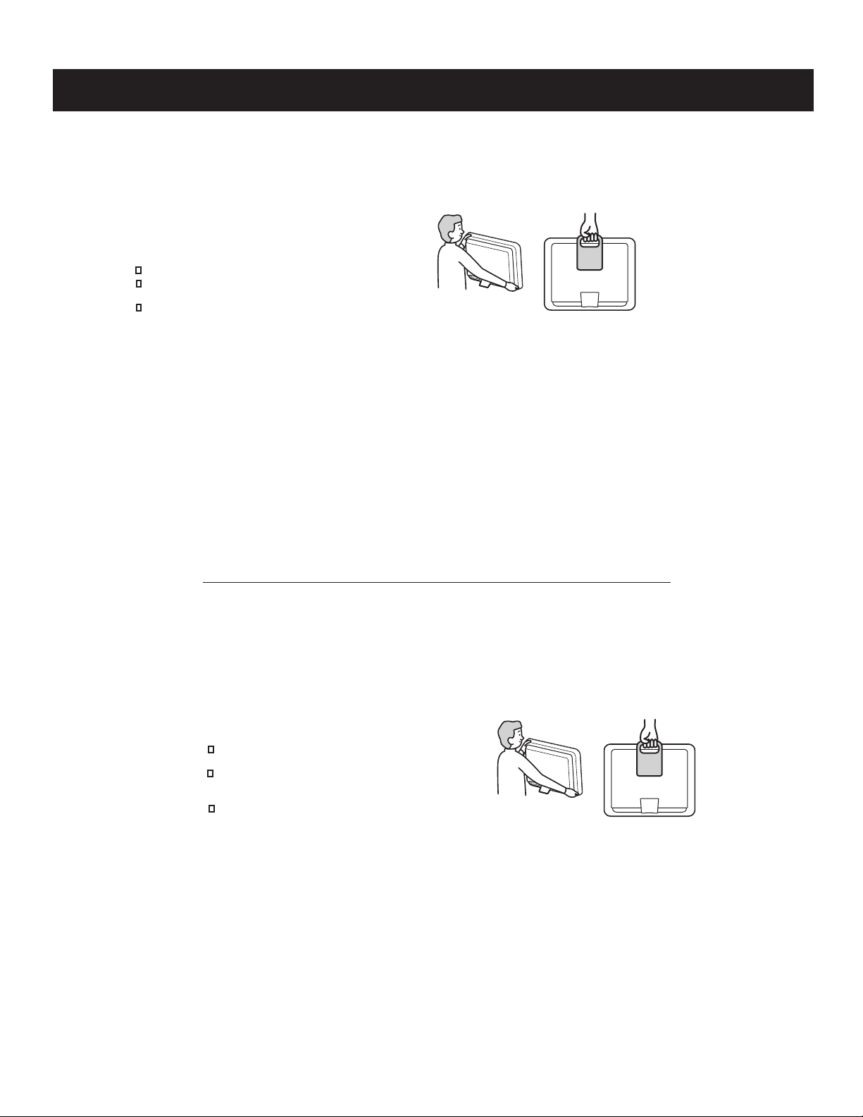
CARRYING THE TV
Carry the TV in the specified manner
To avoid dropping the TV and causing serious injury, be sure to follow
these guidelines:
Before carrying the TV, disconnect all cables.
When you carry the TV without handle, place your hand as
illustrated and hold it securely. Do not put stress on the LCD panel.
When carrying the TV, do not subject it to shocks or vibration,
or excessive force.
Without handle
With handle
WARNING!!
An isolation transformer should be used during any service to avoid possible shock hazard, because of live chassis. The chassis of this receiver is
directly connected to the ac power line.
! SAFETY-RELATED COMPONENT WARNING!!
Components identifi ed by shading and ! mark on the schematic diagrams, exploded views, and in the parts list are critical for safe operation. Replace
these components with Sony parts whose part numbers appear as shown in this manual or in supplements published by Sony. Circuit adjustments that
are critical for safe operation are identifi ed in this manual. Follow these procedures whenever critical components are replaced or improper operation is
suspected.
ATTENTION!!
Ces instructions de service sont à l’usage du personnel de service qualifi é seulement. Pour prévenir le risque de choc électrique, ne pas faire
l’entretien autre que celui contenu dans le Mode d’emploi à moins que vous soyez qualifi é faire ainsi.
POUR TRANSPORTER LE TÉLÉVISEUR
Transport du téléviseur de la manière précisée
Assurez-vous de suivre ces consignes pour éviter de laisser tomber le
téléviseur et de provoquer des blessures graves :
Débranchez tous les câbles avant de transporter le
téléviseur.
Transportez le téléviseur en plaçant les mains tel
qu’illustré et le tenir solidement. N’appliquez pas de
pression sur l’écran ACL.
Lorsque vous transportez le téléviseur, ne le soumettez
pas à des chocs ou vibrations, ni à une force excessive.
Sans poignee de transport
Avec poignee de transport
Afi n d’eviter tout risque d’electrocution provenant d’un chássis sous tension, un transformateur d’isolement doit etre utilisé lors de tout dépannage. Le
chássis de ce récepteur est directement raccordé à l’alimentation du secteur.
! ATTENTION AUX COMPOSANTS RELATIFS A LA SECURITE!!
Les composants identifi es par une trame et par une marque ! sur les schemas de principe, les vues explosees et les listes de pieces sont d’une
importance critique pour la securite du fonctionnement. Ne les remplacer que par des composants Sony dont le numero de piece est indique dans le
present manuel ou dans des supplements publies par Sony. Les reglages de circuit dont l’importance est critique pour la securite du fonctionnement
sont identifi es dans le present manuel. Suivre ces procedures lors de chaque remplacement de composants critiques, ou lorsqu’un mauvais
fonctionnement suspecte.
KDL-19M4000
6

SAFETY-RELATED COMPONENT WARNING
KDL-19M4000
There are critical components used in LCD color TVs that are important for safety. These components are identifi ed with shading and
mark on the schematic diagrams and the electrical parts list. It is essential that these critical parts be replaced only with the part number
specifi ed in the electrical parts list to prevent electric shock, fi re, or other hazard.
NOTE: Do not modify the original design without obtaining written permission from the manufacturer or you will void the original parts and
labor guarantee.
!
USE CAUTION WHEN HANDLING THE LCD PANEL
When repairing the LCD panel, be sure you are grounded by using a wrist band.
When installing the LCD panel on a wall, the LCD panel must be secured using the 4 mounting holes on the rear cover.
To avoid damaging the LCD panel:
do not press on the panel or frame edge to avoid the risk of electric shock.
do not scratch or press on the panel with any sharp objects.
do not leave the module in high temperatures or in areas of high humidity for an extended period of time.
do not expose the LCD panel to direct sunlight.
avoid contact with water. It may cause a short circuit within the module.
disconnect the AC adapter when replacing the backlight (CCFL) or inverter circuit.
(High voltage occurs at the inverter circuit at 650Vrms.)
always clean the LCD panel with a soft cloth material.
use care when handling the wires or connectors of the inverter circuit. Damaging the wires may cause a short.
protect the panel from ESD to avoid damaging the electronic circuit (C-MOS).
LEAKAGE CURRENT HOT CHECK CIRCUIT
KDL-19M4000
7
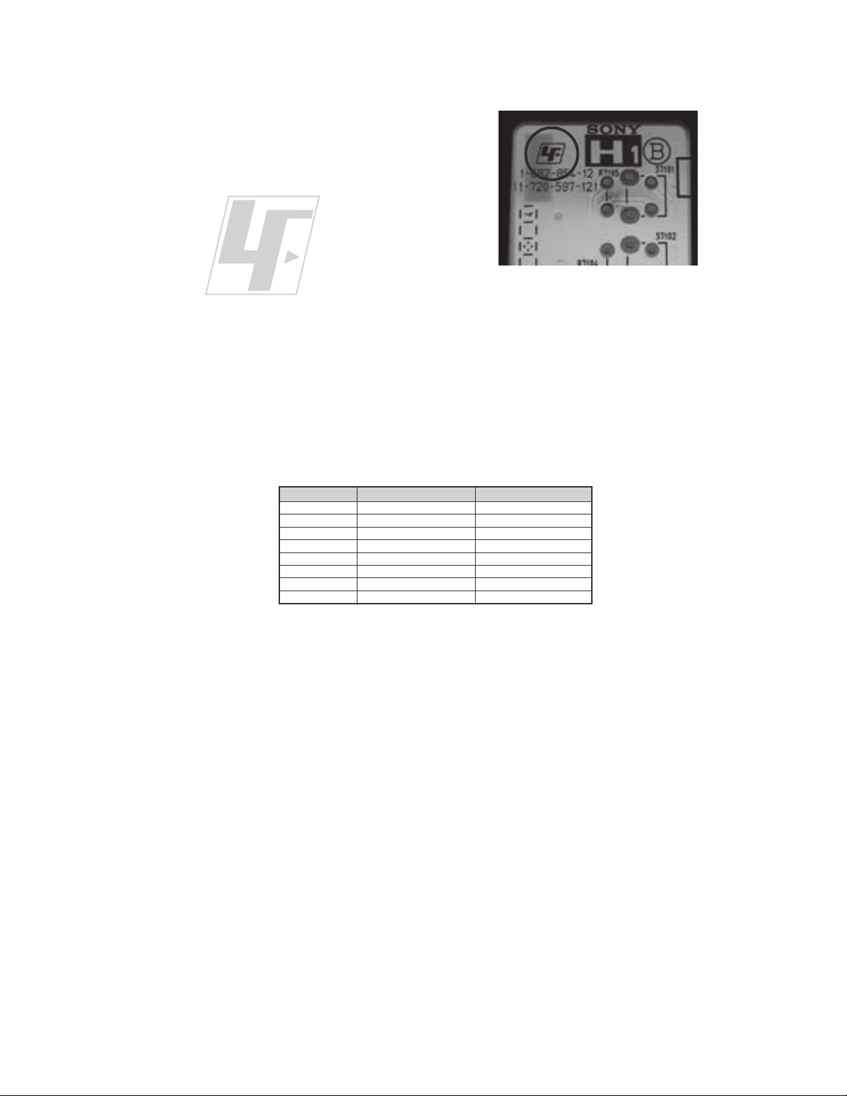
The circuit boards used in these models have been processed using
Lead Free Solder. The boards are identified by the LF logo located
close to the board designation e.g. H1 etc [ see example ]. The
servicing of these boards requires special precautions to be taken as
outlined below.
KDL-19M4000
example 1
It is strongly recommended to use Lead Free Solder material in order to guarantee optimal quality of new solder joints.
Lead Free Solder is available under the following part numbers :
rebmuntraP retemaiD skrameR
91-500-046-7mm3.0gK52.0
02-500-046-7mm4.0gK05.0
12-500-046-7mm5.0gK05.0
22-500-046-7mm6.0gK52.0
32-500-046-7mm8.0gK00.1
42-500-046-7mm0.1gK00.1
52-500-046-7mm2.1gK00.1
62-500-046-7mm6.1gK00.1
Due to the higher melting point of Lead Free Solder the soldering iron tip temperature needs to be set to 370 degrees centigrade.
This requires soldering equipment capable of accurate temperature control coupled with a good heat recovery characteristics.
For more information on the use of Lead Free Solder, please refer to
http://www.sony-training.com
KDL-19M4000
8
SAFETY CHECK-OUT
KDL-19M4000
After correcting the original service problem, perform the following
safety checks before releasing the set to the customer:
1. Check the area of your repair for unsoldered or poorly soldered
connections. Check the entire board surface for solder splashes and
bridges.
2. Check the interboard wiring to ensure that no wires are “pinched” or
touching high-wattage resistors.
3. Check that all control knobs, shields, covers, ground straps, and
mounting hardware have been replaced. Be absolutely certain that
you have replaced all the insulators.
4. Look for unauthorized replacement parts, particularly transistors,
that were installed during a previous repair. Point them out to the
customer and recommend their replacement.
5. Look for parts which, though functioning, show obvious signs of
deterioration. Point them out to the customer and recommend their
replacement.
6. Check the line cords for cracks and abrasion. Recommend the
replacement of any such line cord to the customer.
7. Check the antenna terminals, metal trim, “metallized” knobs, screws,
and all other exposed metal parts for AC leakage. Check leakage as
described below.
The AC leakage from any exposed metal part to earth ground and
from all exposed metal parts to any exposed metal part having a
return to chassis, must not exceed 0.5 mA (500 microamperes).
Leakage current can be measured by any one of three methods.
1. A commercial leakage tester, such as the Simpson 229 or RCA
WT-540A. Follow the manufacturers’ instructions to use these
instructions.
2. A battery-operated AC milliampmeter. The Data Precision 245
digital multimeter is suitable for this job.
3. Measuring the voltage drop across a resistor by means of a VOM
or battery-operated AC voltmeter. The “limit” indication is 0.75
V, so analog meters must have an accurate low voltage scale.
The Simpson’s 250 and Sanwa SH-63TRD are examples of
passive VOMs that are suitable. Nearly all battery-operated digital
multimeters that have a 2 VAC range are suitable (see Figure A).
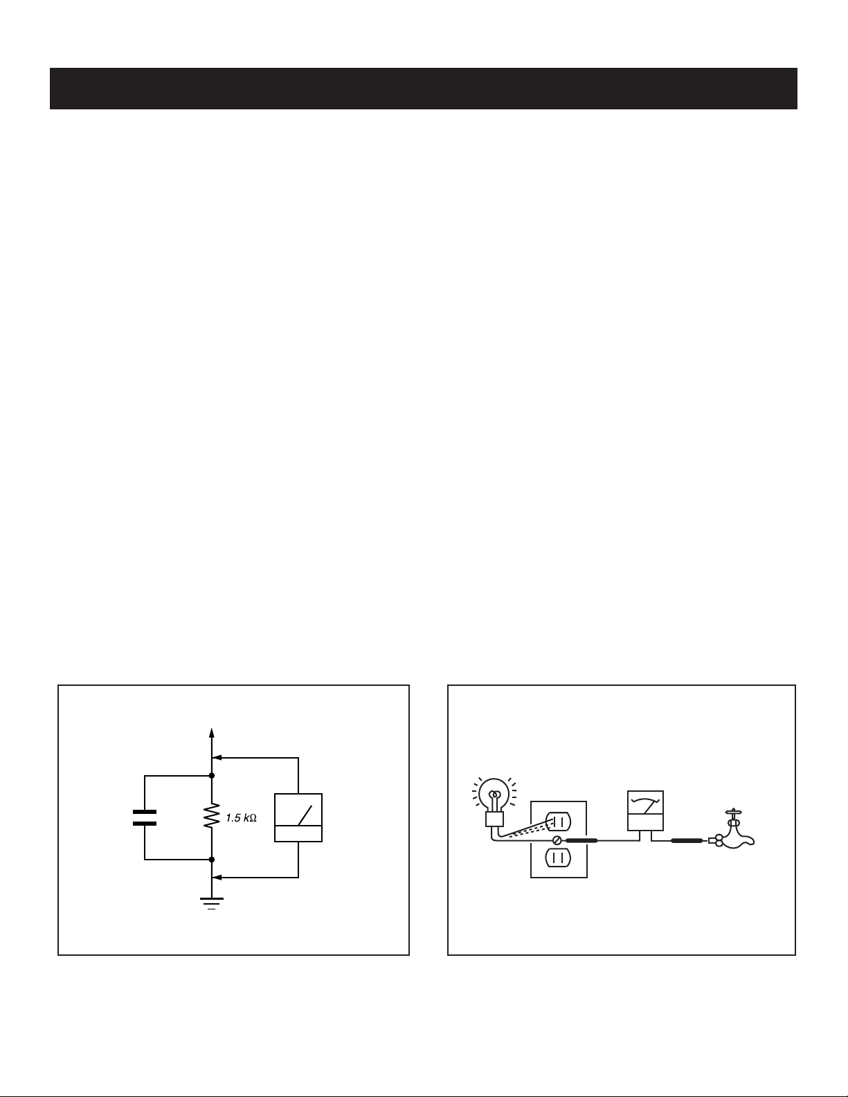
How to Find a Good Earth Ground
A cold-water pipe is a guaranteed earth ground; the cover-plate
retaining screw on most AC outlet boxes is also at earth ground. If the
retaining screw is to be used as your earth ground, verify that it is at
ground by measuring the resistance between it and a cold-water pipe
with an ohmmeter. The reading should be zero ohms.
If a cold-water pipe is not accessible, connect a 60- to 100-watt
trouble- light (not a neon lamp) between the hot side of the receptacle
and the retaining screw. Try both slots, if necessary, to locate the hot
side on the line; the lamp should light at normal brilliance if the screw
is at ground potential (see Figure B).
Leakage Test
0.15 μF
Figure A. Using an AC voltmeter to check AC leakage. Figure B. Checking for earth ground.
To Exposed Metal
Parts on Set
Earth Ground
AC
Voltmeter
(0.75V)
Trouble Light
AC Outlet Box
Ohmmeter
Cold-water Pipe
KDL-19M4000
9

KDL-19M4000
SELF-DIAGNOSTIC FUNCTION
IMPORTANT:
The unit in this manual DOES NOT contain a self-diagnostic function. If an error occurs, the TV will not stay on. It is our recommendation that if a
repair is required for this set, the technician should bring both the A Board and the G Board to the customer location.
Control Buttons
TIMER STANDBY POWER
Description of LED Indictors
The unit in this manual DOES NOT contain a self-diagnostic function.
KDL-19M4000
10

1-1. STAND REMOVAL
1
Place the TV set face down onto the soft cloth
2
Remove 2 screws, +PSW M4X16
3
Hold both sides of the stand fi rmly, and pull out the stand from hinge housing
KDL-19M4000
SECTION 1: DISASSEMBLY
3
Stand Assembly
2
1
1-2. HANDLE
1
Remove 4 screws Handle and Rear Cover, +PSW M4X12
REMOVAL
1
Handle
Rear Cover
KDL-19M4000
11
1-3. REAR COVER REMOVAL
1
Remove 6 screws, +BVTP 4X25
2
Remove 3 screws from Terminal positions, +BVTP 3X10
Remove 2 screws from both sides of Hinge positions, +BVTP 4X12
3
Remove 3 screws from bottom of Rear Cover, +BVTP 3X10
4
1
KDL-19M4000
3
2
4
Rear Cover
1-4. FUNCTION KEY REMOVAL
1
Remove 1 screw and release ground wire, +PSW M3X6
2
Disconnect one connector from H1 Board
3
Release hooks
Function
Touch-Key
Bezel
1
Ground Wire
H1 Board
2
Bezel
KDL-19M4000
3
12
1-5. H2 BOARD REMOVAL
☛
1
Remove 1 screw and release ground wire, +PSW M3X6
2
Disconnect one connector from H3 Board
3
Remove 2 screws, +BVTP 3X10
KDL-19M4000
Side Jack Bracket
H2 Board
3
1
Ground Wire
1-6. A BOARD AND G BOARD REMOVAL
1
Remove 8 screws and release ground wire, +PSW M3X6
2
Remove 4 screws from bottom of Main Shield, +FH 4X5
3
Remove 1 screw, +FH 3X4
4
Remove 2 screws, UNC (HEX)
5
Remove 5 screws, +PSW M3X6
6
Disconnect 8 connectors
7
Remove 1 Nut and 1 screw (+FH3X4) from Tuner
8
Disconnect 5 connectors
9
Remove 6 screws, +PSW M3X6
10
Slide out AC inlet with G Board from Main Bracket
2
Main Shield
2
1
5
3
4
KDL-19M4000
A Board
10
6
7
9
G Board
8
Main Shield
13
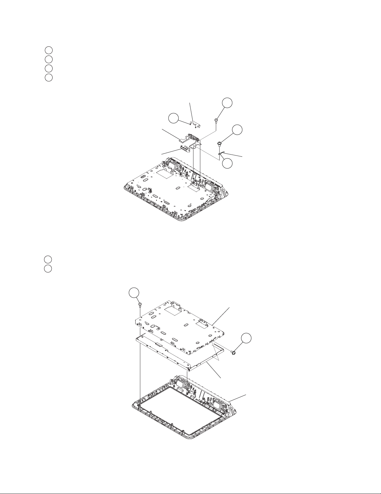
1-7. HINGE REMOVAL
1
Remove 2 screws, +BVTP 4X21
2
Remove 2 screws, +PSW M4X16
3
Release Ground Wire
4
Unhook Bottom and Top Hinge Covers
KDL-19M4000
Hinge Cover (Bottom)
4
Hinge
Hinge Cover (Top)
1-8. LCD PANEL AND MAIN BRACKET REMOVAL
1
Remove 7 screws, +BVTP 3X10
2
Remove 4 screws, +PSW M3X6
1
2
Ground Wire
3
1
LCD Bracket
2
LCD Panel
Bezel
KDL-19M4000
14
 Loading...