

Sony KDL-19L4000, KDL-26L4000 Schematic

SERVICE MANUAL
NEX
CHASSIS
MODEL
DEST
KDL-19L4000
KDL-26L4000
WE / OIRT / UK
WE / OIRT / UK
- 1 -
RM-ED014
FLAT PANEL COLOR TV

TABLE OF CONTENTS
Section Title Page Section Title Page
1. GENERAL ................................................................... 3
Caution................................................................ 3
Specifications ..................................................... 4
Connectors .......................................................... 5
Self Diagnosis..................................................... 7
2. DISASSEMBLY
2-1. Stand & Rear Cover Removal (19 inches) ........ 8
2-2. Rear Cover Removal (26 inches) ....................... 8
2-3. Stand Removal (26 inches) ................................ 8
2-4. Loudspeaker Removal........................................ 8
2-5. Switch Unit Sub Assy Removal......................... 8
2-6. H5 Board Removal ............................................. 9
2-7. B Board Removal ............................................... 9
2-8. Power Board Removal (19 inches) .................... 9
2-9. Power Board Removal (26 inches) .................... 9
4. DIAGRAMS
4-1. Block Diagram 1 (19 inches) ............................. 13
Block Diagram 2 (26 inches) ............................. 14
4-2. Circuit Board Location....................................... 15
4-3. Schematic Diagrams and Printed Wiring
Boards ................................................................. 15
B Board Schematic Diagram.............................. 16
G1D Board Schematic Diagram (26 inches) ..... 30
G Board Schematic Diagram (19 inches) .......... 31
H1 Board Schematic Diagram ........................... 31
H5 Board Schematic Diagram ........................... 31
B Printed Wiring Board .....................................
G Printed Wiring Board (19 inches) .................. 36
G1D Printed Wiring Board (26 inches) ............. 38
H1 Printed Wiring Board ................................... 40
H5 Printed Wiring Board ................................... 40
32
3. ADJUSTMENTS
3-1. How to enter the Service Mode ........................ 10
3-2. Service Menu Structure ..................................... 10
3-2-1. Service General Menu ................................. 10
3-2-2. Service Alignments Menu ........................... 10
3-2-3. Virgin Mode................................................. 11
3-2-4. OSD Service Menu ...................................... 11
3-2-5. Country Selection Menu.............................. 11
3-2-6. Reset............................................................. 11
3-3. White Balance Adjustment ............................... 12
3-3-1. Preparation ................................................... 12
3-3-2. “COOL” White Balance Adjustment .......... 12
3-3-3. “NEUTRAL” White Balance Adjustment .. 12
3-3-4. “WARM” White Balance Adjustment ........ 12
5. EXPLODED VIEWS
5-1a. Chassis (19 inches)............................................. 41
5-1b. Chassis (26 inches)............................................. 42
5-2. Bezel & Stand Assy............................................ 43
5-3a. Rear Cover & Power Supply Cords (19 inches) 44
5-3b. Rear Cover & Power Supply Cords (26 inches) 45
Accessories & Connectors ................................. 46
Remote Commander........................................... 46
WARNING !!
AN ISOLATION TRANSFORMER SHOULD BE USED DURING ANY
SERVICE W ORK TO AVOID POSSIBLE SHOCK HAZARD DUE TO
LIVE CHASSIS, THE CHASSIS OF THIS RECEIVER IS DIRECTLY
CONNECTED TO THE POWER LINE.
SAFETY-RELATED COMPONENT WARNING !!
COMPONENTS IDENTIFIED BY SHADING AND MARKED
THE EXPLODED VIEWS AND IN THE PARTS LIST ARE CRITICAL
FOR SAFE OPERATION. REPLACE THESE COMPONENTS WITH
SONY PARTS WHOSE PART NUMBERS APPEAR AS SHOWN IN
THIS MANUAL OR IN SUPPLEMENTS PUBLISHED BY SONY.
ON
- 2 -
SECTION 1 GENERAL
SECTION 1 GENERAL
CAUTION
Lead Free Soldered Boards
The circuit boards used in these models have been processed using
Lead Free Solder. The boards are identif ied by the LF logo located
close to the board designation e.g. F1, H1 etc [ see examples ]. The
servicing of these boards requires special precautions to be taken as
outlined below.
example 1
example 2
Lead Free Solder material must be used to comply with environmental requirements of new solder joints. Lead Free Solder is available under
the following part numbers :
rebmuntraP retemaiD skrameR
91-500-046-7mm3.0gK52.0
02-500-046-7mm4.0gK05.0
12-500-046-7mm5.0gK05.0
22-500-046-7mm6.0gK52.0
32-500-046-7mm8.0gK00.1
42-500-046-7mm0.1gK00.1
52-500-046-7mm2.1gK00.1
62-500-046-7mm6.1gK00.1
Due to the higher melting point of Lead Free Solder the soldering iron tip temperature needs to be set to 370 degrees centigrade. This requires
soldering equipment capable of accurate temperature control coupled with a good heat recovery characteristics.
For more information on the use of Lead Free Solder, please refer to http://www.sony-training.com
- 3 -
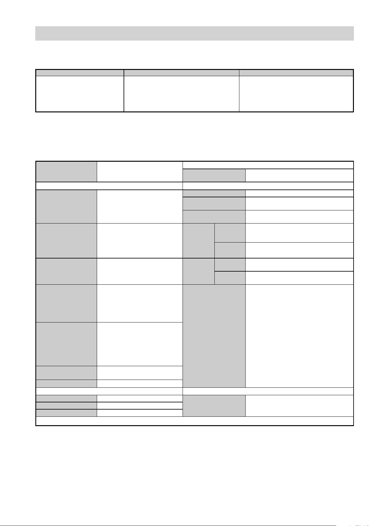
SPECIFICATIONS
Analogue:
Depending on your country/region
B/G/H, D/K, L, I
Digital:
DVB-T
Picture Size
Input/Output Terminals [REAR] General Specifications
1: 21-pin Euro connector
(CENELEC standard)
2: 21-pin Euro connector
(CENELEC standard)
Phono Jacks
Component In
HDMI Inputs
PC Input
CAM Conditional Access Module
Input/Output Terminals [SIDE] Remote control system : Infrared control
Headphone jack Stereo mini jack
Audio input Phono jacks
Video input Phono jack
Television System Channel Coverage Colour/Video System
Analogue: 48.25 - 855.25 MHz
Digital: VHF Band III (177.5 - 226.5 MHz)
/UHF E21 - E69 (474 - 858 MHz)
LCD(Liquid Crystal Display) Panel
Approx 48.1cm (19 inches)
Approx 66.1cm (26 inches)
Inputs for Audio and Video signals.
Inputs for RGB, Inputs for S-Video.
Outputs of Analogue TV Video and
Audio signals.
Inputs for Audio and Video signals.
Inputs for RGB and S Video.
Outputs of Video and Audio signals
Audio input: 500mVrms,
Impedance: 47Kohms
Supported formats: 1080i, 720p,
576p, 576i, 480p, 480i
Y: 1 Vp-p, 75 ohms, 0.3V negative
sync/Pb/Cb: 0.7 Vp-p,
75 ohms/Pr/Cr: 0.7 V p-p, 75 ohms
Audio input: Phono jacks
Video: 1080i, 720p, 576p, 576i,
480p, 480i
Audio: Two channel linear PCM
32, 44.1 and 48kHz,
16, 20 and 24 bits
Analogue audio input: (minijack)
(HDMI IN 2 only)
Video:15 Pin D Sub Connector
Audio: Minijack
Design and specifications are subject to change without notice.
Sound Output
Right and Left speaker
Power Requirements 220 - 240V
Power Consumption
Standby Power
Consumption
With stand
Dimensions
Without
stand
With stand
Weight
Main Features
Power requirements
Without
stand
Analogue:
PAL, SECAM
NTSC 3.58/4.43 (VIDEO IN)
Digita l :
MPEG-2 MP@ML
2 x 5W (RMS) (19 inches)
2 x 10W (RMS) (26 inches)
Approx 48W (19 inches)
Approx 98W (26 inches)
1W or less (19 inches)
0.5W or less (26 inches)
Approx 479x413x191mm (19 inches)
Approx 674x510x242mm (26 inches)
Approx 807x548x101mm (19 inches)
Approx 807x548x101mm (26 inches)
Approx 5.8kg (19 inches)
Approx 11.7kg (26 inches)
Approx 5.3kg (19 inches)
Approx 9.5kg (26 inches)
High Quality Design
"Draw the Line" Concept with wave design
speakers
Thin-looking side edge
Matt black finish
High Usability
Simple, easy-to-use Sony OSD
Input select OSD
Tools menu shortcut
Useful connectivity with Highly-selected
Features
2 HDMI inputs
PC input (D-sub)
SCART x 2
Favourite channels
Channel label
Sleep Timer
3V dc
2 batteries IEC designation
R06 (size AA)
- 4 -
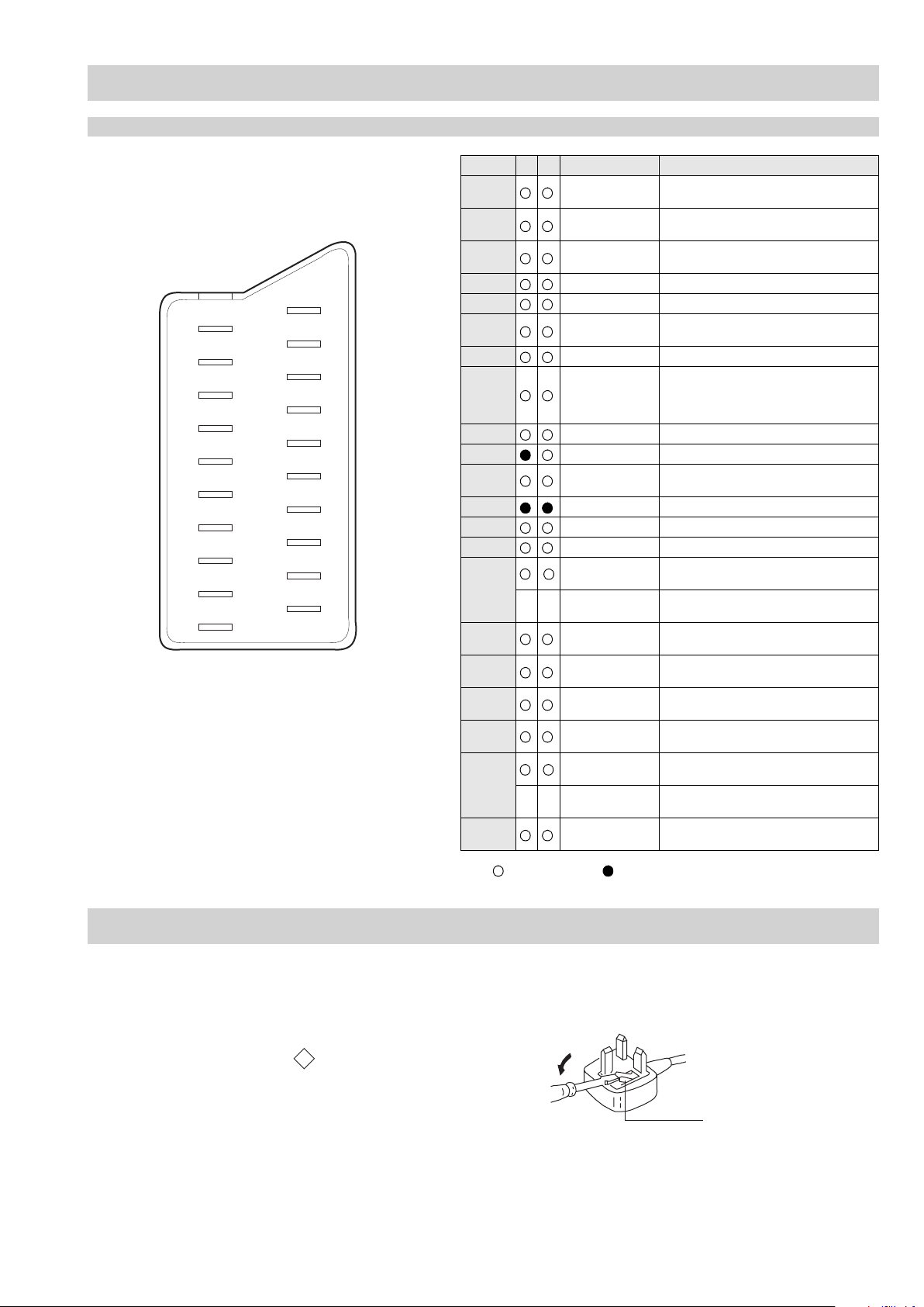
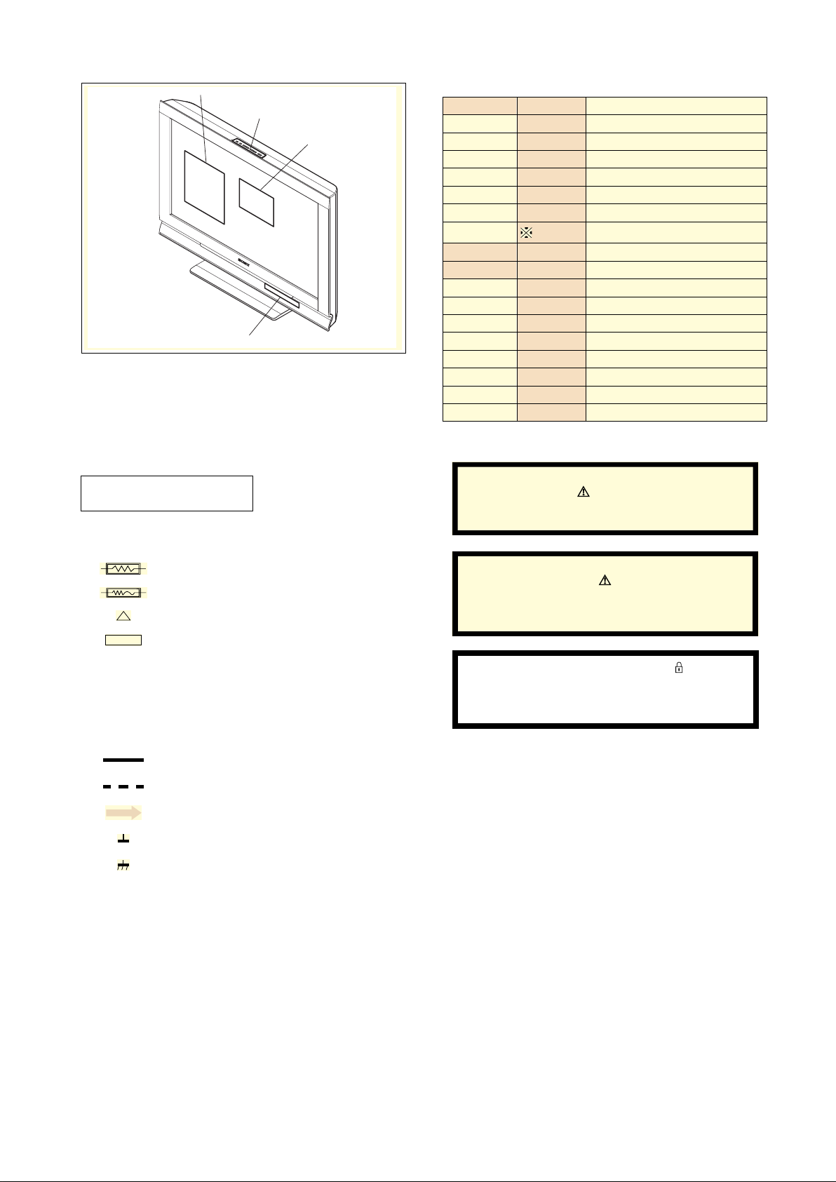
21 Pin Connector (SCART)
How to replace the fuse.
Open the fuse compartment with
a screwdriver blade and replace
the fuse.
FUSE
21
20
19
18
17
16
15
14
13
12
11
10
9
8
7
6
5
4
3
2
1
CONNECTORS
Pin No 1 2 Signal Signal level
1 Audio output B
2
3
4 Ground (audio)
5 Ground (blue)
6 Audio input A
7 Blue input 0.7 +/- 3dB, 75 ohms positive
8 Function select
9 Ground (green)
10 AVlink
11 Green Green signal : 0.7 +/- 3dB, 75 ohms,
12 Open
13 Ground (red)
14 Ground (blanking)
_ _ Red input 0.7 +/- 3dB, 75 ohms, positive
15
_ (S signal Chroma
-
16 Blanking input
17 Ground (video
18 Ground (video
19 Video output 1V +/- 3dB, 75ohms, positive sync 0.3V
Video input 1V +/- 3dB, 75ohms, positive sync 0.3V
20
--
21 Common ground
(right)
Audio input B
(right)
Audio output A
(left)
(left)
(AV control)
-
input)
(Ys signal)
output)
input)
Video input
Y (S signal)
(plug, shield)
Standard level : 0.5V rms
Output impedence : Less than 1kohm*
Standard level : 0.5V rms
Output impedence : More than 10kohm*
Standard level : 0.5V rms
Output impedence : Less than 1kohm*
Standard level : 0.5V rms
Output impedence : More than 10kohm*
High state (9.5-12V) : Part mode
Low state (0-2V) : TV mode
Input impedence : More than 10K ohms
Input capacitance : Less than 2nF
positive
0.3 +/- 3dB, 75 ohms, positive
High state (1-3V) Low state (0-0.4V)
Input impedence : 75 ohms
(-3+10dB)
(-3+10dB)
1V +/- 3dB, 75ohms, positive sync 0.3V
(-3+10dB)
UK PLUG WARNING
WARNING (UK Models only)
The flexible mains lead is supplied connected to a B.S. 1363 fused
plug having a fuse of the correct rating for the set. Should the fuse
need to be replaced, use a fuse of the same rating approved by ASTA
to BS 1362, ie one that carries the
IF THE PLUG SUPPLIED WITH THIS APPLIANCE IS NOT SUITABLE
FOR THE OUTLET SOCKETS IN YOUR HOME, IT SHOULD BE CUT
OFF AND AN APPROPRIA TE PLUG FITTED. THE PLUG SEVERED
FROM THE MAINS LEAD MUST BE DESTROYED AS A PLUG WITH
BARED WIRES IS DANGEROUS IF ENGA GED IN A LIVE SOCKET.
When an alternative type of plug is used, it should be fitted with the
correct rating fuse, otherwise the circuit should be protected by the
same rating fuse at the distribution board.
ASA
T
mark.
- 5 -
Connected Not Connected (open) * at 20Hz - 20kHz
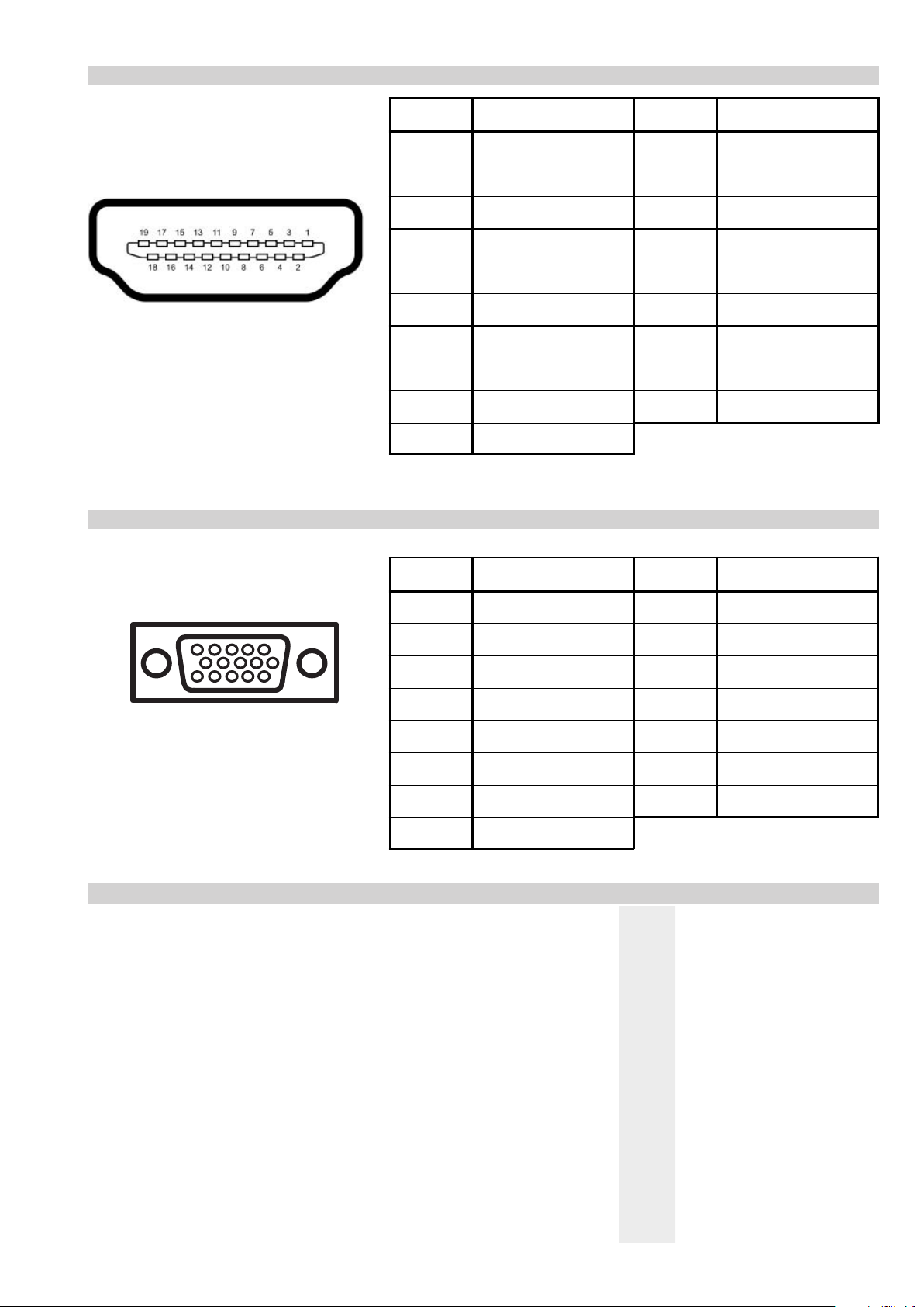
HDMI Connector
1
15 Pin D Sub Connector (PC)
Pin No Signal Assignment Pin No Signal Assignment
1 TMDS Data2+ 11 TMDS Clock Shield
2 TMDS Data2 Shield 12 TMDS Clock-
3 TMDS Data2- 13 CEC
4 TMDS Data1+ 14 Reserved (N.C. on device)
5 TMDS Data1 Shield 15 SCL
6 TMDS Data1- 16 SDA
7 TMDS Data0+ 17 DDC/CEC Ground
8 TMDS Data0 Shield 18 +5V Power
9 TMDS Data0- 19 Hot Plug Detect
10 TMDS Clock+
Pin No Signal Assignment Pin No Signal Assignment
1 Red Out 9 +5V DC
2 Green Out 10 Sync Return (Ground)
3 Blue Out 11 Monitor ID0 in Display
4 Unused 12 DCC Ser ial Data
5 Ground 13 Horizontal Sync
6 Red Return 14 Vertical Sync
7 Green Return (Ground) 15 DCC Seri al Clock
8 Blue Return (Ground)
Rear Connection Panel Side Connection Panel
- 6 -
NEX SELF DIA GNOSTIC SOFTWARE
IMPORTANT:
The TV sets in this manual DO NOT contain a self-diagnostic function. If an error occurs, the TV will not stay on. It is recommended that if a
repair is required for these TV sets, the technician should take both the A Board and the Power Unit Board to the customer location.
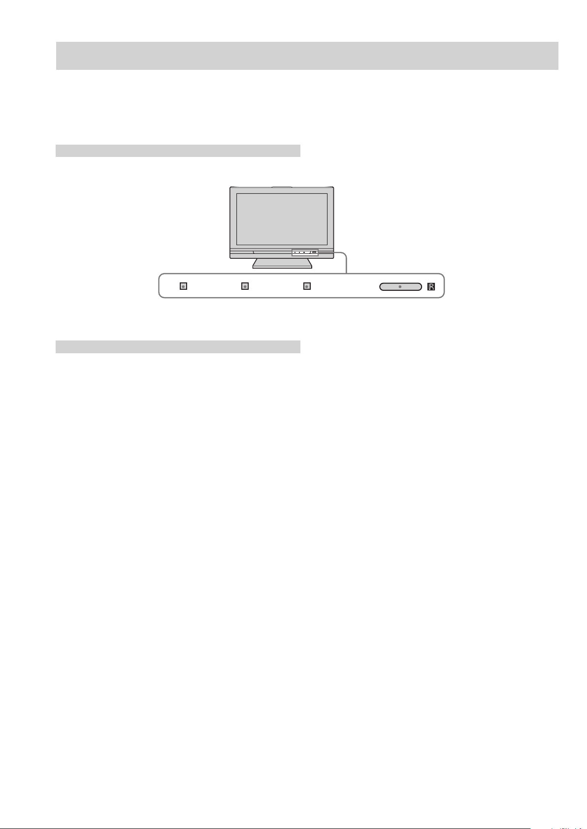
Control LED’s
TIMER STANDBY POWER
LED Error Codes and Descriptions
The TV sets in this manual DO NOT contain a self-diagnostic function.
- 7 -
SECTION 2 DISASSEMBLY
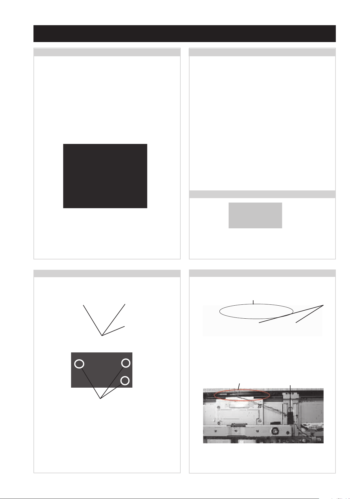
2-1. Stand & Rear Cover Removal (19 inches)
The stand must be removed before the rear cover can be
removed.
=>
=>
Remove the 3 fixing screws indicated and lift the TV off
the stand.
4) 2-580-603-01 SCREW, +PSW M4 X 16 1 Screw
1
=>
=>
1
=>
1
=>1=>
1
Remove the rear cover fixing screws indicated and pull the
rear cover gently backwards away from the back of the
TV set.
Screw Part number(s) and Description(s)
1) 2-580-639-01 SCREW, +BVTP2 4 X 12 9 Screws
2) 7-685-646-79 SCREW, +BVTP 3 X 8 3 Screws
=>
1
=>
=>
=>
2
=>
1
=>
1
2
=>
2
=>
1
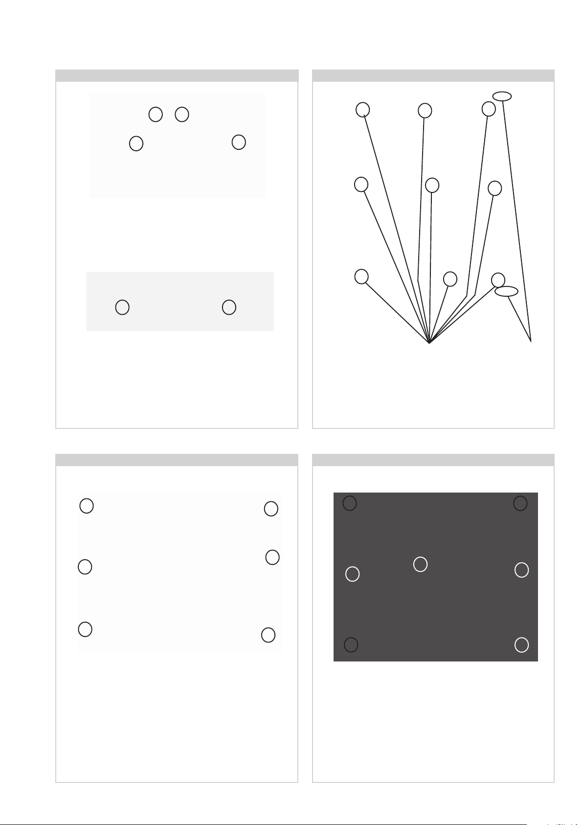
2-2. Rear Cover Removal (26 inches)
Remove the rear cover fixing screws indicated and pull the
rear cover gently backwards away from the back of the
TV set.
Screw Part number(s) and Description(s)
1) 2-580-640-01 SCREW, +BVTP2 4 X 16 14 Screws
2) 2-580-606-01 SCREW, +PSW M5X8 1 Screw
3) 7-685-646-79 SCREW, +BVTP 3 X 8 3 Screws
2-3. Stand Removal (26 inches)
Remove the 3 stand fixing screws indicated.
Screw Part number(s) and Description(s)
2-580-603-01 SCREW, +PSW M4X16 3 Screws
=>
=>
=>
=>
1
=>
1
=>
1
2-4. Loudspeaker Removal
19 inch
Screws
26 inch
Screws
T o remove the ‘Loudspeaker’ disconnect the speaker
cables and remove the 3 screws circled. The loudspeaker
can then be pulled gently backwards away from the back
of the TV set.
The same process is used for the left and right speakers.
Screw Part number(s) and Description(s)
2-580-639-01 SCREW, +BVTP2 4X12 3 Screws (for each speaker) (19 inches)
2-580-640-01 SCREW, +BVTP2 4X16 3 Screws (for each speaker) (26 inches)
2-5. Switch Unit Sub Assy Removal
19 inch
Open the clamps holding the wire harness. Disconnect the
harness from the main board. The Key Board sub assy
can now be lifted from its guide boss.
26 inch
Remove the felt from the wire harness. Disconnect the
harness from the main board. The Key Board sub assy
can now be lifted from its guide boss.
Guide
Boss
Guide
Boss
Clamps
Felt
- 8 -
2-6. H5 Board Removal
Remove the STAND-BKT by removing the 4 screws
circled. The H5 board will now be exposed.
Screw Part number(s) and Description(s)
2-580-639-01 SCREW, +BVTP 4 X 12 4 Screws
2-7. B Board Removal
T o remove the H5 Boar d disconnect the wire harness
and remove the screws circled.
Screw Part number(s) and Description(s)
7-685-646-79 SCREW, +BVTP 3 X 8 2 Screws
2-8. Power Board Removal (19 inches)
=>
1
=>
1
Screws
Disconnect the 6 harnesses from the board. Remove the side
cover by releasing the clips at the top and bottom of the
bracket. Remove the 9 screws circled. The board can then be
carefully lifted from the TV.
Screw Part number(s) and Description(s)
4-382-854-01 SCREW, +PSW M3 X 8 9 Screws
2-9. Power Board Removal (26 inches)
=>
1
=>
1
=>
1
=>
=>
2
2
Clips
=>
1
=>
1
=>
1
Disconnect the 4 harnesses from the board. Remove the 6
screws circled and ease the board gently away from the back
of the TV set.
Screw Part number(s) and Description(s)
1) 4-382-854-01 SCREW, +PSW M3 X 8 6 Screws
=>
1
1
=>
1
Disconnect the 3 harnesses from the board. Remove the 7
screws circled and ease the board gently away from the back
of the TV set.
Screw Part number(s) and Description(s)
1) 4-382-854-01 SCREW, +PSW M3 X 8 5 Screws
2) 7-685-646-79 SCREW, +BVTP 3 X 8 2 Screws
- 9 -
=>
1
SECTION 3 ADJUSTMENTS
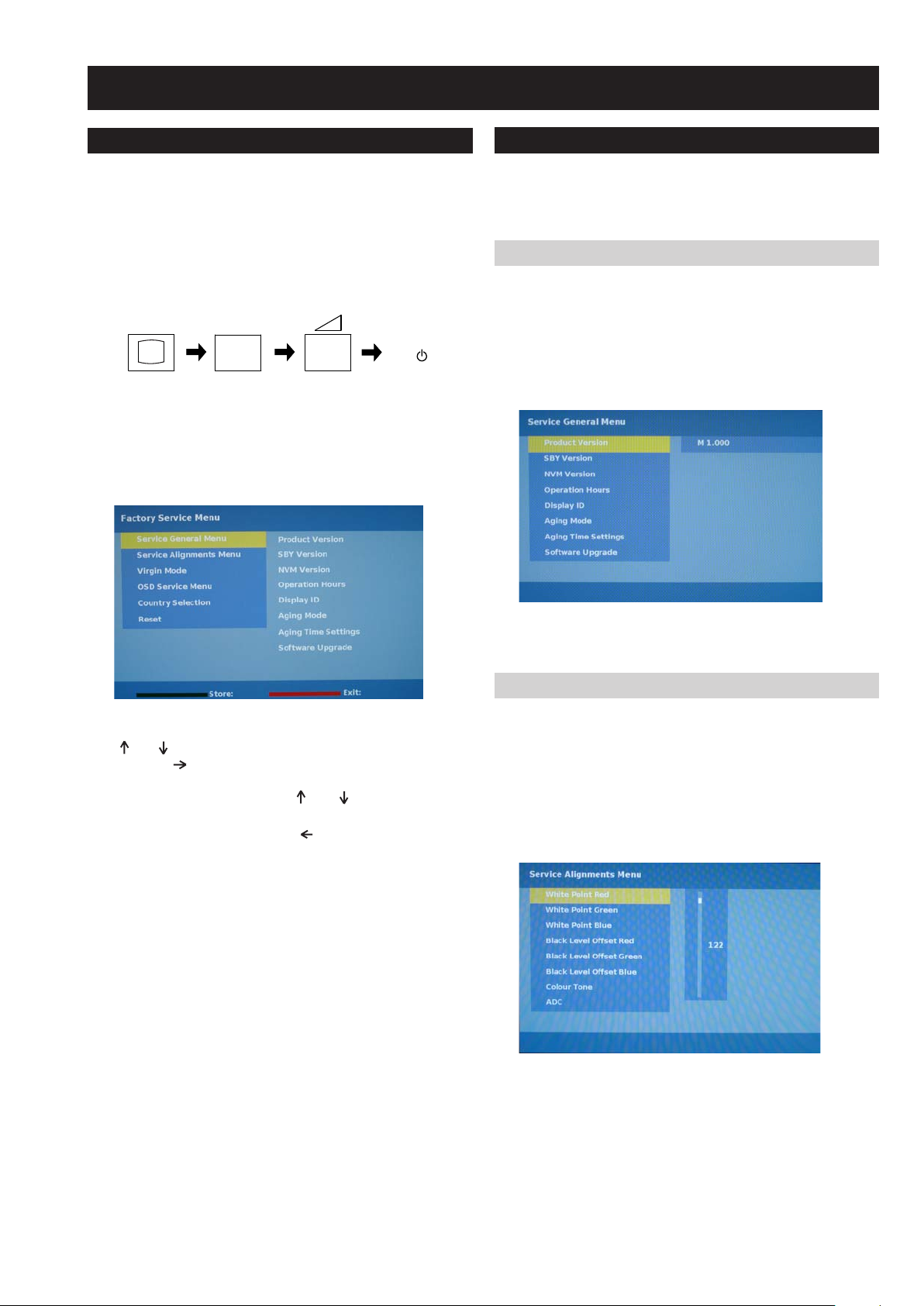
3-1. How to enter the Service Mode
Service adjustments to this model can be performed using the
supplied Remote Commander RM-ED014.
1. Turn on the po wer to the TV set.
2. Press the following sequence of buttons on the Remote
Commander.
i+
(ON SCREEN (DIGIT 5) (VOLUME +) (TV)
DISPLAY)
3. The following menu appears on the screen (See Pic.1).
Pic.1
5
+
+
TV
I/
3-2. Service Menu Structure
The following description shows the items that can be
viewed and/or adjusted using the Service Menu.
3-2-1. Service General Menu
The following menu appears on the screen when you enter
the ‘Service General Menu’ (See Pic.2). This menu allows
you to view the product information, set the TV into Aging
Mode and perform Software Upgrade to the TV set.
Pic.2
4. Move to the corresponding adjustment item using the
‘ ’ or ‘ ’ arrow buttons on the Remote Commander.
5. Press the ‘ ’ arrow button to enter into the required menu
item.
6. Adjust the data value using the ‘ ’ or ‘ ’ arrow buttons on
on the Remote Commander.
7. T o go back at any time press the ‘ ’ button on the Remote
Commander.
8. Press the Red button or ‘Menu’ button on the Remote
Commander to quit the Service Mode when all adjustments
have been completed.
• After carrying out the service adjustments, to prevent the
customer accessing the ‘Service Menu’ switch the TV set
OFF and then ON again.
3-2-2. Service Alignments Menu
The following menu appears on the screen when you enter
the ‘Service Alignments Menu’ (See Pic.3). This menu
allows adjustment of the TV picture levels. These adjustments
are set during manufacture and should not normally require
further adjustment.
Pic.3
- 10 -
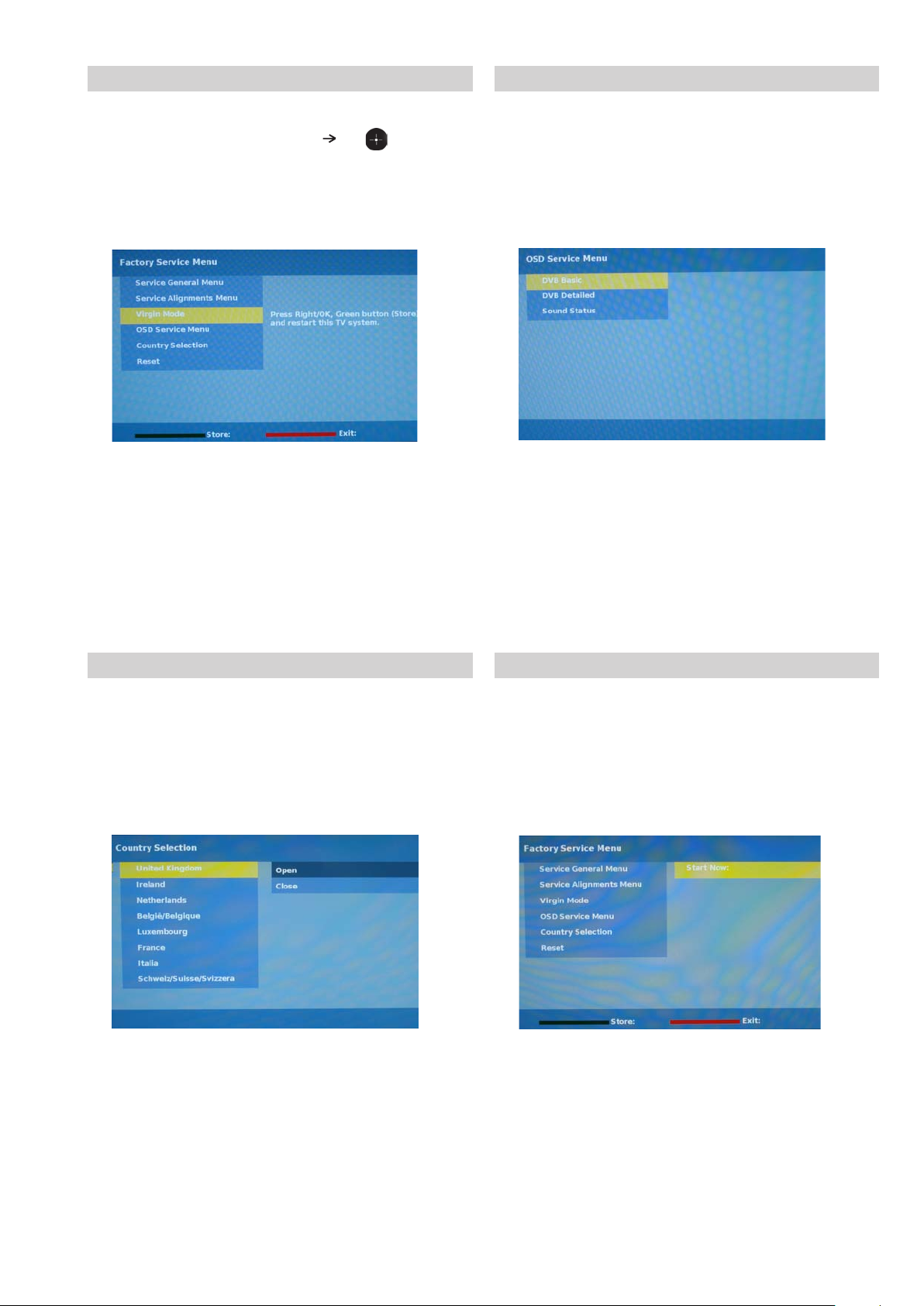
3-2-3. Virgin Mode 3-2-4. OSD Service Menu
Selection of ‘Virgin Mode’ (See Pic.4), allows the writing of
default data to the NVM. Select the ‘ ’ or ‘ ’ and the
Green button to store the data. Restart the TV.
Pic.4
The following menu appears on the screen when you enter
the ‘OSD Service Menu’ (See Pic.5). This menu
allows viewing and adjustment of the AGC and vie wing of the
Sound Status.
Pic.5
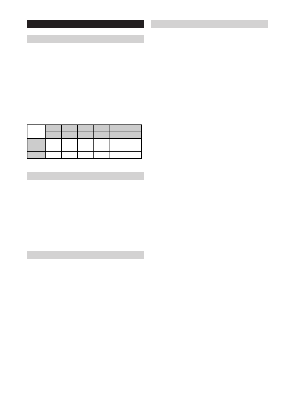
3-2-5. Country Selection Menu
The following menu appears on the screen when you enter
the ‘Country Selection Menu’ (See Pic.6). Using this menu
the destination country of the TV can be set.
Pic.6
3-2-6. Reset
Selection of ‘Reset’ (See Pic.7) allows the TV to be reset to
factory shipping condition. This will restore all settings to those
which were contained in the TV on first shipment.
Pic.7
- 11 -
3-3. White Balance adjustment
3-3-4. “W ARM ” White Balance Adjustment
3-3-1. Preparation
1. Allow approximately 30 minutes for the set to warm up
before proceeding with the white balance adjustment.
2. Connect the signal source to the 3 terminals of the
Component In input (Y/Pb/Pr).
3. Set the Picture Mode to “VIVID” in the user menu.
4. Select the Component In input.
5. Open the Factory Service Menu (see section 3-1.) and select
“Service Alignments Menu”.
6. Set “White Point Red”, “White Point Green”, “White Point
Blue” and “Black Level Offset Red”, “Black Level Offset
Green”, “Black Level Offset Blue” to average values as
shown in Table 1.
Table 1
Red Green Blue Red Green Blue
Gain Gain Gain Offset Offset Offset
Cool 122 119 127 0 7 3
Neutral 127 117 113 1 6 2
Warm 127 107 73 2 6 2
1. Select “W ARM” from Color T one in Service Alignments
Menu.
2. Input 70IRE full white pattern signal into Component In.
3. Adjust “White Point Red”, “White Point Green”, “White Point
Blue” in Service Alignments Menu if needed.
4. Input 25IRE full white pattern signal into Component In.
5. Adjust “Black Level Offset Red”, “Black Level Offset Green”,
“Black Level Offset Blue” in Service Alignments Menu if
needed.
6. Repeat steps 2 to 5 to achieve desired White Balance.
7. Save the settings.
3-3-2. “Cool ” White Balance Adjustment
1. Select “COOL” from Color T one in Service Alignments
Menu.
2. Input 70IRE full white pattern signal into Component In.
3. Adjust “White Point Red”, “White Point Green”, “White Point
Blue” in Service Alignments Menu if needed.
4. Input 25IRE full white pattern signal into Component In.
5. Adjust “Black Level Offset Red”, “Black Level Offset Green”,
“Black Level Offset Blue” in Service Alignments Menu if
needed.
6. Repeat steps 2 to 5 to achieve desired White Balance.
3-3-3. “NEUTRAL ” White Balance Adjustment
1. Select “NEUTRAL” from Color T one in Service Alignments
Menu.
2. Input 70IRE full white pattern signal into Component In.
3. Adjust “White Point Red”, “White Point Green”, “White Point
Blue” in Service Alignments Menu if needed.
4. Input 25IRE full white pattern signal into Component In.
5. Adjust “Black Level Offset Red”, “Black Level Offset Green”,
“Black Level Offset Blue” in Service Alignments Menu if
needed.
6. Repeat steps 2 to 5 to achieve desired White Balance.
- 12 -
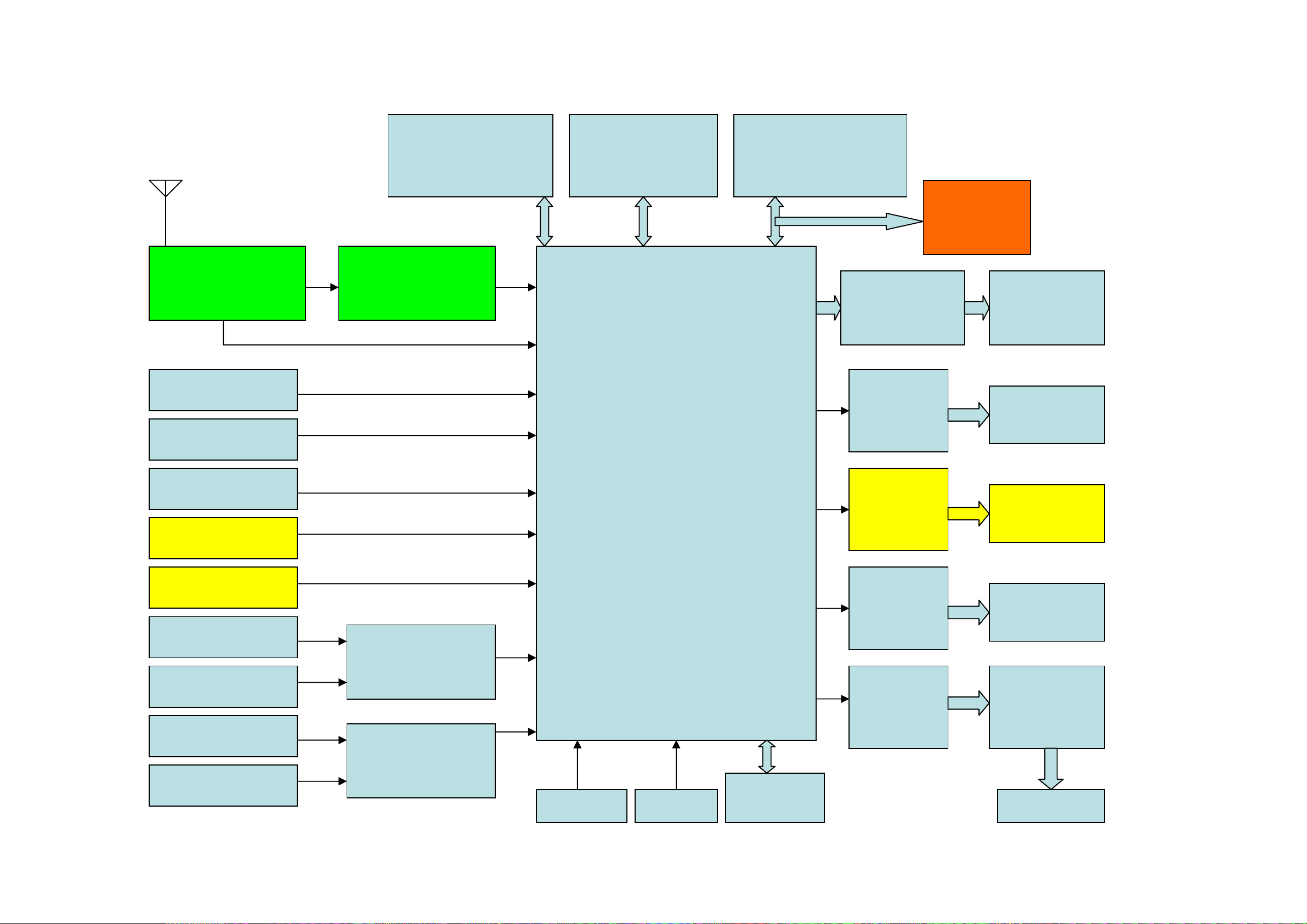
4-1. BLOCK DIA GRAM 1 (19 inches)
TV Control
Source Select
3D-Comb
Digital Color Decoder
Audio Decoder
Full Audio Processing
MPEG2 Decoder
4-Field MA DI
10bit Video Processing
Enhanced PQ Processing
Single LVDS Output
HDMI/DVI
CI
Tuner
ENG37E10KF
PNX8541
Channel Decoder
TDA10048HN
DDR2 64MB x 2
EDE5116AJBG-6E-E
NAND FLASH 64MB
NAND512W3A2CN6E
SPI FLASH 128KB
M25P10
CA
PCMCIA Slot
DUAL LVDS
OUTPUT
1680x1050
Side CVBS + L/R in
Y/Pb/Pr + L/R in
PC in
SCART1 in/out
SCART2 in/out
HDMI SWITCH
CXB1444R
AUDIO SWITCH
CD4052BPW
HDMI1
HDMI2
PC AUDIO IN
DVI AUDIO IN
KEY in IR in
OP AMP
NJM4556AM
OP AMP
NJM4558AM
OP AMP
NJM4558AM
OP AMP
NJM4558AM
HEADPHONE
OUTPUT
SCART AUDIO
OUTPUT
AUDIO LINE
OUTPUT
CLASS D AMP
TFA9810T/N1
SPEAKERS
NVM 8KB
M24C64
LVDS
TRANSIMITTER
THC63LVD823
- 13 -
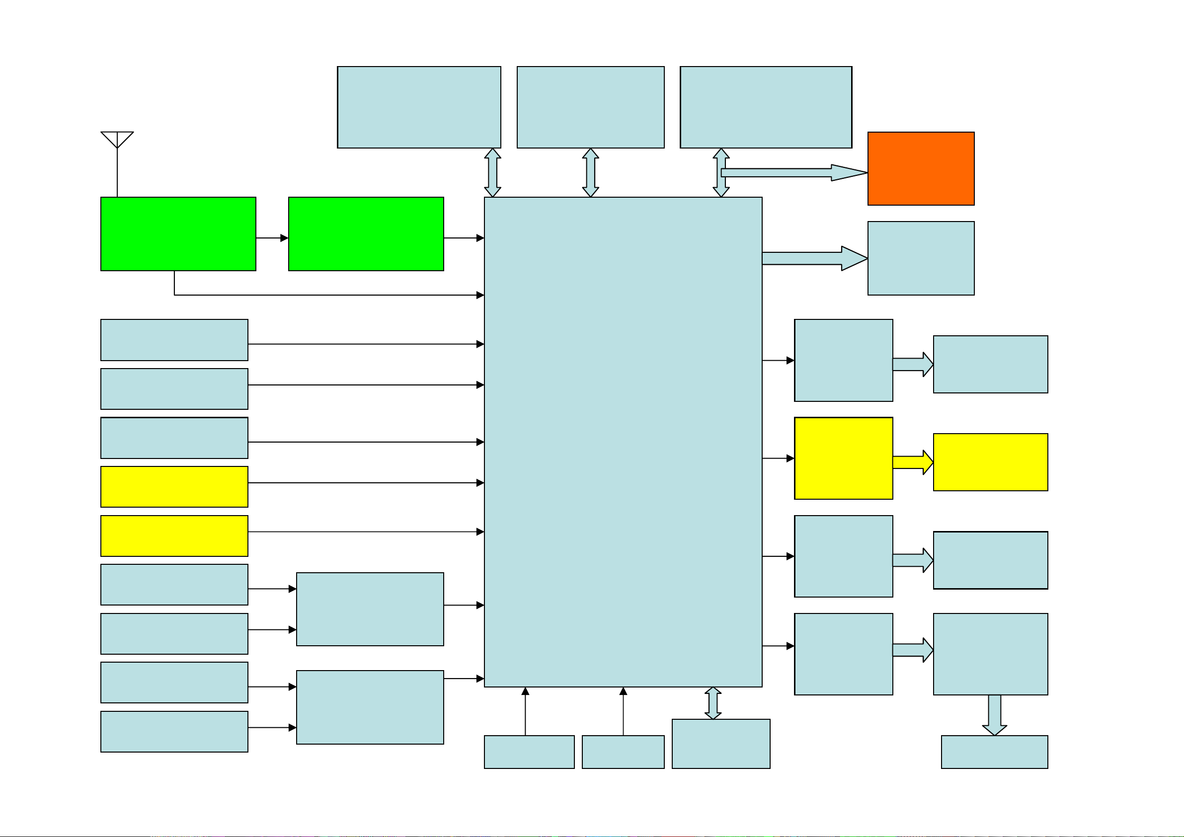
4-1. BLOCK DIA GRAM 2 (26 inches)
TV Control
Source Select
3D-Comb
Digital Color Decoder
Audio Decoder
Full Audio Processing
MPEG2 Decoder
4-Field MA DI
10bit Video Processing
Enhanced PQ Processing
Single LVDS Output
HDMI/DVI
CI
PNX8541
Channel Decoder
TDA10048HN
DDR2 64MB x 2
EDE5116AJBG-6E-E
NAND FLASH 64MB
NAND512W3A2CN6E
SPI FLASH 128KB
M25P10
CA
PCMCIA Slot
LVDS output
1366x768
Side CVBS + L/R in
Y/Pb/Pr + L/R in
PC in
SCART1 in/out
SCART2 in/out
HDMI SWITCH
CXB1444R
AUDIO SWITCH
CD4052BPW
HDMI1
HDMI2
PC AUDIO IN
DVI AUDIO IN
KEY in IR in
OP AMP
NJM4556AM
OP AMP
NJM4558AM
OP AMP
NJM4558AM
OP AMP
NJM4558AM
HEADPHONE
OUTPUT
SCART AUDIO
OUTPUT
AUDIO LINE
OUTPUT
CLASS D AMP
TFA9810T/N1
SPEAKERS
NVM 8KB
M24C64
Tuner
ENG37E10KF
- 14 -
4-2. CIRCUIT BO ARD LOCA TION
5-2. CIRCUIT BOARD LOCATION
B
B
H1
H1
G
C
G
C
N
VM
CVM Board
H
D1
4-3. SCHEMA TIC DIA GRAMS AND
5-3. SCHEMATIC DIAGRAMS AND
PRINTED WIRING BOARDS
PRINTED WIRING BOARDS
Note :
• All capacitors are in µF unless otherwise noted.
• pF : µµF 50WV or less are not indicated except for
electrolytic types.
• Indication of resistance, which does not have one for
rating electrical power, is as follows.
Pitch : 5mm
Electrical power rating : 1/4W
• Chip resistors are 1/10W
• All resistors are in ohms.
k = 1000 ohms, M = 1000,000 ohms
• : nonflammable resistor.
• : fusible resistor.
• : internal component.
• : panel designation or adjustment for repair.
• All variable and adjustable resistors have
characteristic curve B, unless otherwise noted.
• All voltages are in Volts.
• Readings are taken with a 10Mohm digital mutimeter.
• Readings are taken with a color bar input signal.
• Voltage variations may be noted due to normal production
tolerences.
•: B + bus.
A
A Board
H5 (IR & LED)
H5 (IR & LED)
D
S1 Board
D2
A
J
A1
A2
Reference Information
RESISTOR RN
RC
FPRD
FUSE
RS
RB
RW
COIL LF-8L
CAPACITOR TA
PS
PP
PT
MPS
MPP
ALB
ALT
ALR
Note :
The components identified by shading
and marked are critical for safety.
Replace only with the part numbers
specified in the parts list.
Note :
Les composants identifiés par une trame et
par une marque sont d'une importance
critique pour la sécurité. Ne les remplacer
que par des pièces de numéro spécifié.
specified.
Note :
The components identified by mark
confidential information.
Strictly follow the instructions whenever the
components are repaired and/or replaced.
: METAL FILM
: SOLID
: NON FLAMMABLE CARBON
: NON FLAMMABLE FUSIBLE
: NON FLAMMABLE METAL OXIDE
: NON FLAMMABLE CEMENT
: NON FLAMMABLE WIREWOUND
: ADJUSTMENT RESISTOR
: MICRO INDUCTOR
: TANTALUM
: STYROL
: POLYPROPYLENE
: MYLAR
: METALIZED POLYESTER
: METALIZED POLYPROPYLENE
: BIPOLAR
: HIGH TEMPERATURE
: HIGH RIPPLE
contain
• : B - bus.
• : RF signal path.
• : earth - ground.
• : earth - chassis.
- 15 -
 Loading...