

Page 1

LCD Projection TV KDF-60XBR950/KDF-70XBR950
4-097-520-11 (1)
LCD Projection TV
HD-Monitor
Operating Instructions
KDF-60XBR950
KDF-70XBR950
2003 Sony Corporation
Page 2

WARNING
To prevent fire or shock hazard, do not
expose the LCD Projection TV t o rain or
moisture.
CAUTION
RISK OF ELECTRIC SHOCK
DO NOT OPEN
ATTENTION
RISQUE DE CHOC ELECTRIQUE,
NE PAS OUVRIR
PRECAUCION
RIESGO DE CHOQUE ELECTRICO
NO ABRIR
Note to CATV system installer
This reminder is provided to call the CATV system
installer’s attention to Article 820-40 of the NEC that
provides guidelin es for proper grounding and, in
particular, specifies that the cable ground shall be
connected to the grounding system of the building, as
close to the point of cable entry as practical.
Use of this television receiver for other than pri vate
viewing of programs broadcast on UHF, VHF,
transmitted by cable companies or satellite for the
use of the general public may require authorization
from the broadcaster/cable company and/or
program owner.
CAUTION : TO REDUCE THE RISK OF ELECTRIC SHOCK,
DO NOT REMOVE COVER (OR BACK).
NO USER-SERVICEABLE PARTS INSIDE.
REFER SERVICING TO QUALIFIED SERVICE PERSONNEL.
This symbol is intended to alert the user to the
presence of uninsulated “dangerous voltage”
within the product’s enclosure that may be of
sufficient magnitude to constitute a risk of
electric shock to persons.
This symbol is intended to alert the user to the
presence of impor tant operating and
maintenance (servicing) instructions in the
literature accompanying the appliance.
CAUTION
To prevent electric shock, do not use this polarized AC
plug with an extension cord, receptac le or other outlet
unless the blades can be fully inserted to prevent blade
exposure.
Note on Caption Vision
This television receiver provides display of television
closed captioning in accordance with §15.119 of the FCC
rules.
Owner’s Record
The model and serial numbers ar e lo cat ed at the rear of
the LCD Projection TV, below the Sony logo, on the
sticker, and also on the TV box (white label). Record
these numbers in the spaces provided below. Refer to
them whenever you call upon your Sony dealer regarding
this product.
Model No.
Serial No. ______________________
NOTIFICATION
This equipment has been tested and found to comply with
the limits for a Class B digital device pursuant to Part 15
of the FCC Rules. These limits are designed to provide
reasonable protection against harmful interference in a
residential installation. This equipment generates, uses,
and can radiate radio frequency energy and, if not
installed and used in accordance with the instructions,
may cause harmful interference with radio
communications. However, there is no guarantee that
interference will not occur in a particular installation. If
this equipment does cause harmful interference to radio
or television reception, which can be determined by
turning the equipment off and on, the user is encouraged
to try to correct the interference by one or more of the
following measures:
❑ Reorient or relocate the receiving antennas.
❑ Increase the separation between the equipment and
receiver .
❑ Connect the equipment into an outlet on a circuit
different from that to which the receiver is
connected.
❑ Consult the dealer or an experienced radio/TV
technician for help.
You are cautioned that any changes or
modifications not expressly approved in
this manual could void your warranty and
your authority to operate this equipment.
This document is for the remote control RM-Y914.
MODEL: KDF-60XBR950, KDF-70XBR950
Please keep this notice with the instruction manual.
2
Page 3
Safety
❑ Operate the LCD Projection TV only on 120 V AC.
❑ The plug is designed, for safety purposes, to fit into
the wall outlet only one way. If you are unable to
insert the plug fully into the outlet, contact your
dealer.
❑ If any liquid or solid object should fall inside the
cabinet, unplug the LCD Projection TV immediately
and have it checked by qualified service personnel
before operating it further.
❑ If you will not be using the LCD Projection TV for
several days, disconnect the power by pulling the
plug itself. Never pull on the cord.
For details concerning safety precautions, see
“Important Safeguards” on page 4.
Installing
❑ To prevent internal heat buildup, do not block the
ventilation openings.
❑ Do not install the LCD Projection TV in a hot or
humid place, or in a place subject to excessive dust
or mechanical vibra tion.
❑ Avoid operating the LCD Projection TV at
temperature below 41°F (5°C).
❑ If the LCD Projection TV is transported directly
from a cold to a warm location, or if the room
temperature changes suddenl y, the picture may be
blurred or show poor colo r. In this case, pl ease wait
a few hours to let the moisture evaporate before
turning on the LCD Projection TV.
❑ To obtain the best picture, do not expose the screen
to direct illumination or direct sunlight. It is
recommended to use spot lighting directed down
from the ceiling or to cover the windows that face
the screen with opaque drapery. It is desirable to
install the LCD Projection TV in a room where t he
floor and walls are not of a reflective material.
“Dolby”, “Pro Logic”, and the doub le-D symbol are
trademarks of Dolby Laboratories.
ATTENTION
Pour prévenir les choc s é lectriques, ne pas util iser cette
fiche polarisée avec un prolongateur, une prise de courant
ou une autre sortie de courant, sauf si les lames peuvent
tre inserées à fond sans en laisser auc une partie à
decouvert.
As an ENERGY STAR® Partner, Sony
Corporation has determined that
this product meets the E
®
S
TAR
guidelines for energy
efficiency.
NERGY STAR
E
®
is a U.S. registered mark.
TruSurround, SRS and the ( )
®
symbol are trademarks
NERGY
of SRS Labs, Inc.
TruSurround technology is incorporated unde r license
from SRS Labs, Inc.
BBE and BBE Symbol are trademarks of BBE Sound,
Inc. and are licensed by BBE Sound, Inc. under U.S.
Patent No. 4,638,258 and 4,482,866.
3
Page 4

Important Safety Instructions
1) Read these instructions.
2) Keep these instructions.
3) Heed all warnings.
4) Follow all instructions.
5) Do not use this apparatus near water.
6) Clean only with dry cloth.
7) Do not block any ventilation openings. Install in
accordance with the manufacturer’s instructions.
8) Do not install near any heat sources such as radiators,
heat registers, stoves, or other apparatus (including
amplifiers) that produce heat.
9) Do not defeat the safety purpose of the polarized or
grounding-type plug. A polarized plug has two
blades with one wider than t he other. A grounding
type plug has two blades and a third grounding prong.
The wide blade or the third prong are provided for
your safety. If the provided plug do es not fit into
your outlet, consult an electrician for replacement of
the obsolete outlet.
10) Protect the power cord from being walked on or
pinched particularly at plugs, convenience
receptacles, and the point where they exit from the
apparatus.
11) Only use attachments/accessories specified by the
manufacturer.
12) Use only with the cart, stand, tripod,
bracket, or table specified by the
manufacturer, or sold with the apparatus.
When a cart is use d , us e ca ution when
moving the cart/apparatus combination
to avoid injury from tip-over.
13) Unplug this apparatus during lightning storms or
when unused for long periods of time.
14) Refer all servicing to qualified service personnel.
Servicing is required when the apparatus has been
damaged in any way, such as power-supply cord or
plug is damaged, liquid has been spilled or objects
have fallen in to th e appa ratus, the apparatus has been
exposed to rain or moisture, does not operate
normally, or has been dropped.
15) Apparatus shall not be exposed to dripping or
splashing and no objects filled with liquids, such as
vases, shall be placed on the apparatus.
Important
Safeguards
For your protection, please read these instructions
completely, and keep this manual for future reference.
Carefully observe and comply with all w arnings, cautions
and instructions pla ced on the set or described in the
operating instructions or service manual.
WARNING
To guard against injury, the following basic safety
precautions should be observed in the installation, use
and servicing of the set.
Use
Power Sources
This set should be operated only from
the type of power source indicated on
the serial/model plate. If you are not sure
of the type of electrical power supplied
to your home, consult your dealer or
local power company. For those sets designed to operate
from battery power, refer to the operating instructions.
Grounding or P olarization
This set is equipped with a polarized AC power cord plug
(a plug having one blade wider than the other), or with a
three-wire grou nd ing type plug (a plug h aving a third pin
for grounding). Follow the instructions below:
For the set with a polarized AC power cord
plug
This plug will fit into the po wer ou tlet
only one way. This is a safety feature.
If you are unable to insert the plug
fully into the outlet, try reversing the
plug. If the plug still fails to fit,
contact your electrician to have a suitable outlet installed.
Do not defeat the safety purpose of the polarized plug by
forcing it in.
Alternate Warning for the set with a threewire grounding type AC plug
This plug will only fit into a groundingtype power outlet. This is a safety
feature. If you are unable to insert the
plug into the outlet, contact your
electrician to have a suitable outlet
installed. Do not defeat the safety purpose of the
grounding plug.
4
Page 5

Overloading
Do not overload wall o utl ets, e xte nsio n
cords or convenience receptacles
beyond their capacity, since this can
result in fire or electric shock.
Always turn the set off when it is not
being used. When the set is left
unattended and unused for long
periods of time, unplug it from the
wall outlet as a precaution against th e
possibility of an internal malfunction that could create a
fire hazard.
If a snapping or pop ping s oun d fro m a TV
set is continuous or frequent whil e the TV
is operating, unplug the TV and c onsult
your dealer or service technician. It is
normal for some TV sets to make
occasional snapping or popping sounds,
particularly when being turned on or off.
Object and Liquid Entry
Never push objects of any kind into the
set through the cabinet slots as they may
touch dangerous voltage points or short
out parts that could result in a fire or
electric shock. Never spill liquid of any
kind on the set.
Attachments
Do not use attachments not
recommended by the manufacturer, as
they may cause hazards.
Cleaning
Clean the cabinet of the LCD Projection
TV with a dry soft cloth. To remove dust
from the screen, wipe it gen tly with a soft
cloth. Stubborn stains may be removed
with a cloth slightly dampened with
solution of mild soap and warm water. Never use strong
solvents such as thinner or benzine for cleaning.
If the picture becomes dark after using the LCD
Projection TV for a long period of time, it may be
necessary to clean the inside of th e LCD Projection TV.
Consult qualified servi ce personnel.
On contamination on the screen surface
The screen surface has a special coating t o reduce a
picture displayed by reflecting . If you clean the screen
surface in the wrong way, the screen may be damaged. T o
clean the screen, do as follows:
❑ Clean the screen with a soft cloth, such as the
supplied clean i ng clo t h or a gla s s cle an in g clo t h .
❑ To remove hard contamination, use the supplied
cleaning cloth or a glass cleaning cloth moistened
with a solution of mild detergent and water.
❑ Do not use any type of abrasive pad, alkaline
cleaner, acid cleaner, scouring powder, chemical
cloth, or solvent such as alcohol, benzene or thinner,
as these may scratch the screen's coat ing.
Installation
Water and Moi sture
Do not use power-line operated sets
near water — for example, near a
bathtub, washbowl, kitc hen sink, or
laundry tub, in a wet basement, or
near a swimming pool, etc.
Accessories
Do not place the set on an unstable
cart, stand, table or shelf. The set may
fall, causing serious i njury to a chil d or
an adult and seriou s da m a ge to th e se t.
Use only a cart or stand recommended
by the manufacturer for the specific
model of LCD Projection T V. An appliance and cart
combination should be moved with care. Quick stops,
excessive force, and uneven surfaces may cause the
appliance and cart combination to overturn.
Ventilation
The slots and openings in the cabinet and in the back or
bottom are provided for necessary ventilation. To ensure
reliable operation of the set, and to protect it from
overhe at i ng , the s e s l ots and openings mus t never be
blocked or covered.
❑ Never cover the slots and openings
with a cloth or other materials.
❑ Never block the slots and openings
by placing the set on a bed, sofa, rug
or other similar surface.
5
Page 6
❑ Never place the set in a confined
space, such as a bookcase or built-i n
cabinet, unless proper ventilat ion is
provided.
Antenna Grounding According to the NEC
Refer to section 54 -300 of Canadian Elec trical Code for
Antenna Ground in g.
❑ Do not place the set near or over a
radiator or heat register, or where it is
exposed to direct sunlight.
Pow er-Cord Protection
Do not allow anything to rest on or roll
over the power cord, and do not place the
set where the power cord is subject to
wear or abuse.
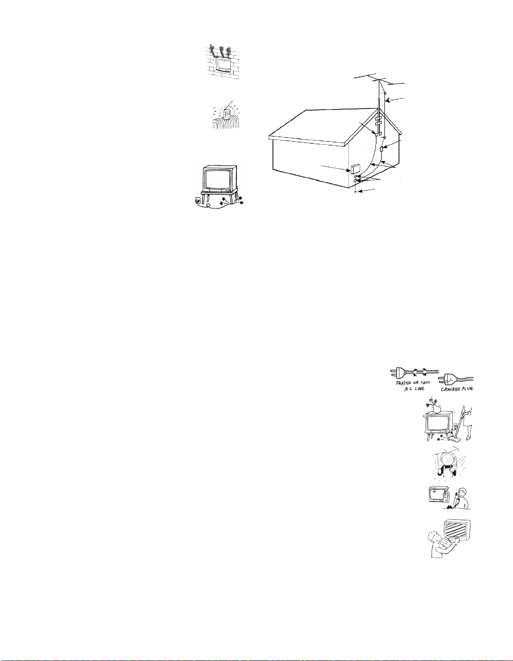
Antennas
Outdoor Antenna Grounding
If an outdoor antenna is installed, follow the precautions
below. An outdoor antenna system should not be lo cated
in the vicinity of overhead power lines or other electric
light or power circuits, or where it can come in contact
with such power lines or circuits.
WHEN INSTALLING AN OUTDOOR ANTENNA
SYSTEM, EXTREME CARE SHOULD BE TAKEN TO
KEEP FROM CONTACTING SUCH POWER LINES
OR CIRCUITS AS CONTACT WITH THEM IS
ALMOST INVARIABLY FATAL.
Be sure the antenna system is grounded so as to provide
some protection against vo ltage sur ges and b uilt-up static
charges.
Section 810 of the National Electrical Code (NEC) in
USA and Section 54 of the Canadi an Electrical Code in
Canada provides information with respect to proper
grounding of the mast and supporting structure,
grounding of the lea d-in wire to an antenn a dis c h arge
unit, size of grounding conductors, location of antenna
discharge unit, connecti on to grounding electrodes, and
requirements for the grounding elect rode.
Antenna lead-in wire
Ground clamp
Antenna lead-in wire
Electrical
service
equipment
NEC: National
Electrical Code
(NEC Section 810-20)
Grounding conductors
(NEC section 810-21)
Ground clamps
Power service grounding
electrode system (NEC Art
250 Part H)
Lightning
For added protection for this television receiver during a
lightning storm, or when it is left unattended and unused
for long periods of time, unplug it from the wall outlet
and disconnect the antenna. This will prevent damage to
the receiver due to lightning and power-line surges.
Service
Damage Requiring Service
Unplug the set from the wall outlet and refer servicing to
qualified service personnel under the following
conditions:
❑ When the power cord or
plug is damaged or f rayed.
❑ If liquid has been spilled into
the set.
❑ If the set has been exposed
to rain or water.
❑ If the set has been subject to
excessive shock by being
dropped, or the cabinet has
been damaged.
❑ If the set does not operate
normally when following the
operating instructions.
Adjust only those controls
that are specified in the
operating instructions.
Improper adju s t m en t of
other controls may result in
damage and will often require extensive work by a
qualified technician to restore the set to normal
operation.
❑ When the set exhibits a distinct change in
performance, it indicates a need for service.
6
Page 7
Servicing
Do not attempt to service the set by yourself
since opening the cabinet may expose you to
dangerous voltage or other hazards. Refer all
servicing to qualified service personnel.
Replacement Parts
When replacement parts are required, be sure the service
technician certifies in writing that he has used
replacement parts specif ied by the manufactu rer that ha ve
the same characteristics as the origi nal parts.
Unauthorized substitutions may result in fire , electric
shock or other hazards.
Safety Check
Upon completion of any service or repairs
to the set, ask the service technician to
perform routine safety checks (as specified
by the manufacturer) to determine that the
set is in safe operating condition, and to so
certify. When the set reaches the end of its
useful life, improper disposal could result
in a picture tube implosion. Ask a qualified
service technician to dispose of the set.
For Safety
Be careful when moving
the LCD Projection TV
When you place the LCD Projection
TV in position, be careful not to
drop it on your foot or fingers.
Watch your footing while installing the LCD Projection
TV.
Carry the LCD Projection TV in
the specified manner
If you carry the LCD Projec tio n TV in a
manner other than the specified manner
and without the specified number of
persons, it may drop and a serious injury
may be caused. Be sure to follow the instructions
mentioned below.
❑ Carry the LCD Projection TV with the specified
number of pers ons (see page 18) .
❑ Do not carry the LCD Projection TV holding the
speaker grill.
❑ Hold the LCD Projection TV tightly when carrying
it.
About the LCD Projection TV
Although the LCD projection TV is made with highprecision techno logy, black dots may appear or bright
points of light (red, b lue, or gree n) may ap pear cons tantly
on the LCD screen. This is a structural property of the
LCD panel and is not a malfunction.
Installation
❑ If direct sunlight or other strong illumination shines
on the screen, part of the screen may appear white
due to reflections from behind the screen. This is a
structural property of the LCD Projection TV.
Do not expose the screen to direct illumination or
direct sunlight.
❑ The picture quality may be affected by yo ur vie win g
position. If you sit too close to the TV, you may
suffer f ro m e ye fatigue.
For the best picture quality, install your LCD
projection TV according to the operating
instructions.
Sit at least 2.2 m (approx. 7 ft.) for KDF-60XBR950
or 2.6 m (approx. 8 ft.) for KDF-70XBR950 away
from your LCD projection TV, and within 60° of the
vertical vi ewing area, and 130° of the horizon t al
viewing area.
❑ When installing your LCD Projection TV against a
wall, keep it at least 10 cm (4 inches) from the wall.
❑ Avoid installing the LCD projection TV near a
heater, etc.
Projection lamp
❑ Your LCD projection TV uses a projection lamp as
its light source. When the projection lamp wears out
after using the LCD projection TV for a long period
of time, the screen image becomes dark, or no image
will appear on the display. If the lamp replacement
indicator of the front panel blinks in red, repla c e the
lamp with a new one (not supplied). In some cases,
the bulb bursts inside the lamp unit noisily, but the
lamp unit is securely designed so that the pieces of
broken glass remain inside the lamp unit. (See
“Replacing the Lamp” on page 13.)
Cooling fan
❑ This LCD projection TV uses a cooling fan to
prevent the internal temperature from heating up.
You might hear the noise from the cooling fan,
depending on the plac e yo u ins ta ll the LCD
projection TV.
7
Page 8

Contents
Introducing the Sony LCD Projection
TV
Presenting the Sony LCD Projection TV.................9
Using This Manual.............................. .... ...............10
Enjoying Your LCD Projection TV.......................11
Replacing the Lamp...............................................13
Installing and Connecting the LCD
Projection TV
Contents.................................................................17
Inserting Batteries into the Remote Control..........17
Carrying Your LCD Projection TV.......................18
To Prevent the LCD Projection TV from Falling
Down..............................................................19
When Installing Your LCD Projection TV
Against a Wall...............................................19
Recommended Viewing Area ................................20
LCD Projection TV Controls and Conn ecto rs.......21
Basic Connections: Connecting a Cable or
Antenna..........................................................25
Connecting a VCR and Cable................................32
Connecting a VCR and Cable Box........................33
Connecting Two VCRs for Tape Editing ..............35
Connecting a Satellite Receiver.............................36
Connecting a Satellite Receiver with a VCR.........37
Connecting an Audio Receive r.................. .... ........39
Connecting a DVD Player with Component
Video Connectors..........................................40
Connecting a DVD Player with A/V Connectors ..41
Connecting a Camcorder .......................................42
Connecting a Device with an Optical
IN Connector..................................................43
Using the CONTROL S Feature............................44
Setting Up the LCD Projection TV
Automatically.................................................45
Using the Features
Using the Remote Control.....................................46
Programming the Remote Contro l.........................48
Using Other Equipment with Your LCD Projection
TV Remote Control .................................. .... .50
Watching the TV....................................................52
Using Favorite Channels................. ...................... .54
Using Twin View™...............................................55
Using the Freeze Function.....................................58
Using Wide Screen Mode......................................59
Using the Digital Program Guide
Displaying the Digital Program Guide..................60
Using the Memory Stick Viewer
About Memory Stick.............................................64
Inserting and Removing a Memory Stick..............66
Using the Memory Stick Index..............................69
Viewing Photos......................................................71
Playing Movies............................................... .... ...74
Memory Stick Index Menu Bar Options...............76
Notes on Using Memory Stick Media...................78
Using i.LINK
About i.LINK.........................................................80
Selecting an i.LINK Device...................................83
Using the i.LINK Control Panel............................84
i.LINK Setup..........................................................86
Using the Menus
Overview................................................................87
Using the Video Menu...........................................88
Using the Audio Menu...........................................92
Using the Screen Menu..........................................94
Using the Channel Menu.......................................96
Using the Parent Menu ..........................................98
Using the Setup Menu .........................................102
Other Information
Overview..............................................................106
Glossary...............................................................107
Contacting Sony............................ .... ...................108
Troubleshooting...................................................108
Flashing Indicators on the Front of the Monitor..114
Specifications.......................................................115
8
Page 9

Introducing the Sony LCD Projection TV
Presenting the Sony LCD Projection TV
Thank you for purchasing the Sony LCD Projection TV.
This manual is for models KDF-60XBR950 and KDF-70XBR950.
Features Some of the features that you will enjoy with your new LCD projection TV
include:
❑ Integrated HDTV: You can watch digital television programs and
enjoy the improved audio/video quality offered by these programs.
❑ DRC
❑ CineMotion
❑ Twin View
❑ Memory Stick
❑ Parental Control: V-Chip technology allows parents to block
❑ Digital Visual Interface (DVI-HDTV): Can accommodate a copy-
®
(Digital Reality Creation) Multifunction V1: Unlike
conventional line doublers, the DRC feature converts frames reproduced
every 1/60 th of a seco nd in real time, m inimizing th e blur or g host of t he
motion images (for 480i signals only).
™
: Using the reverse 3-2 pull down technology, the
CineMotion feature allows you to obtain a smooth picture movement
when playing back movies or other video sources on film.
™
: Using Multi-Image Driver (MID-X), Twin View allows
you to watch two programs side by side with the ability to zoom in on
one picture and listen to the program in the selected window. You can
watch pictures from two different sources (1080i, 720p, 480p or 480i)
simultaneously.
®
Viewer: Allows you to view on your LCD Projection
TV screen digital photos (JPEG) and movies (MPEG1) that are stored
on Memory Stick media.
unsuitable programming for younger viewers.
protected digital connection (HDCP
set-top boxes) that have compatible interfaces. The DVI-HDTV input
terminal is compliant with the EIA-861 standard and is not intended for
use with per s onal compute rs.
*
) to other devices (such as digital
Introducing the Sony LCD Projection TV
* High-bandwidth Digital Content Protection
(Continued)
9
Page 10

Introducing the Sony LCD Projection TV
❑ i.LINK: Provides a secure digital interface to other digital home
entertainment devices. i.LINK allows for the secure transfer of
copyright-protected high-definition content between these devices and
your LCD projection TV. The i.LINK is not compatible with pers onal
computers.
❑ Component Video Inputs: Offers the best video quality for DVD
(480p, 480i) and Digital Set-top box (1080i, 720p, 480p, 480i)
connections.
❑ S-VIDEO Inputs: Provides a high-quality image for connected
equipment.
❑ Favorite Channel Preview : Preview up to sixteen favorite channels
without leaving the current channel.
❑ Wide Screen Mode: Allows you to watch 4:3 normal broadcasts in
wide screen mode (16:9 aspect ratio).
❑ Auto Wide: All ows you to select the wide screen mode automatically.
Using This Manual
We recommend that you carefully review the contents of the following three
sections in the order shown to ensure that you fully un derst and the operat ion
of your new LCD projection TV.
10
1 Installing and Connecting the LCD Projection TV
This section guides you through your initial setup. It shows you how to
install your LCD projectio n TV, to connect your new compon ents and to
connect the antenna and cable.
2 Using the Features
This section shows you how to begin using your new LCD projection
TV. It also shows you how to use your remote control functions.
3 Using the menus
This section teaches you ho w to access on-screen menus and adjus t your
LCD projection TV settings.
Instructions in this manual are written for the remote control. Similar
controls are also found on the LCD projection TV console.
Page 11

Introducing the Sony LCD Projection TV
Enjoying Your LCD Projection TV
Screen
Indicators
The indicators show the current status of your LCD projection TV.
Screen
To minimize screen reflection, its surface has a special coating. Read the
instructions “Use of the Cleaning Cloth” on page 12 carefully before
cleaning.
Inappropriate cleaning methods could damage the finishing.
Projection lamp
Your LCD projection TV uses a projection lamp as its light source. Note the
following:
Projection lamp
Introducing the Sony LCD Projection TV
Indicators
❑ After turning on y our LCD pr ojection TV, it may tak e a whi le be fore t he
picture appears (1 minute or less).
❑ When the projection lamp wears out, the screen image becomes dark.
Replace the lamp with a new Sony XL-2100U replacement lamp (not
supplied).
✍ Be sure to attach the lamp cover securely; otherwise, your LCD
projection TV will not turn on. For details on lamp replacement, see
“Replacing the Lamp” on page 13.
✍ The light emitted from the lamp is quite bri ght when your LCD proj ection
TV is in use. To avoid eye discomfort or injury, do not look into the
housing when the power is on.
11
Page 12

Introducing the Sony LCD Projection TV
Notes on the LCD
Projection TV
To enjoy clear pictures
Be sure not to allow sunlight or light from a lamp to shine directly onto
❑
the screen.
❑ The screen surface is easily scratched. Do not rub, touch , or tap it with a
sharp or abrasive object (see “Use of the Cleaning Cloth” below).
On moisture condensation
❑
If your LCD project ion TV is t ransp orted directly from a cold to a w arm
location, is placed in a humid room, or if the room temperature changes
suddenly, the picture may be blurred or show poor color. This is
because moisture has condensed on the lenses inside. If this happens,
leave the power on and let the moisture evaporate before using your
LCD projection TV.
When the LCD projection TV will not be used for a long period of time
❑
Turn off the main power on the front of your LCD projection TV before
going to sleep or going out. Disconnect the AC plug if idle for more
than 7 days.
When turning off the power
Be sure to turn off the power switch on the main unit or on the remote
❑
control. After turning off the power, the fan will continue to blow for
about two minutes. Be sure to wait for several minutes after turning the
power off when unplugging from the outlet or switch ing t h e break er of f.
Use of the Cleaning
Cloth
12
When carrying the LCD Projection TV
❑
Before carrying, unplug the power cord and disconnect all cables.
Do not carry the LCD projection TV by placing hands under the front
screen.
To remove dust from the front of the screen, wipe w ith the supplied Cleaning
Cloth.
✍ Do not use any type of abrasive pad, alkaline cleaner, scouring powder,
window cleaners or solvent such as alcohol or benzene. Otherwise, this
type of contact may result in a damaged screen.
✍ To clean the screen, please use the supplied Cleani ng Cloth lig htly
moistened with water diluted mild detergent solution. Do not app ly heavy
press when cleaning.
✍ The supplied Cleaning Cloth is washable with warm water and a mild
detergent solution, and can be used repeatedly.
Page 13

Introducing the Sony LCD Projection TV
Replacing the Lamp
Introducing the Sony LCD Projection TV
The projection lamp has a limited life which illuminates the picture.
If the screen becomes dark, the color looks unusual, or the LAMP indicator
on the front of the LCD projection TV flashes, it is time to replace the lamp
with a new one (not supplied).
WARNING
Electric appliances can cause fire or high temperature, resulting in injury
or death. Be sure to follow the instructions below.
❑ Use a Sony XL-2100U replacement lamp (not supplied) for
replacement. Failure to do so may damage the LCD projection TV.
❑ Do not remove the lamp for any purpose other than replacement.
Failure to do so may cause fire or a skin burn.
❑ Before replacing the lamp, turn the power off on the main unit, then
several minutes later, unplug the power cord. (The cooling fan will
continue to blow for about two minutes after turning the power off.)
❑ Before replacing the lamp, let it cool down completely, as the surface of
the lamp remains extremely hot for at least 30 minutes after the power
has been turned off.
❑ Do not leave the removed lamp near flammable materials or within the
reach of children.
❑ Do not pour water onto the removed lamp, or put any object inside the
lamp. Doing so may cause the lamp to burst.
❑ Do not put flammable materials and metal objects inside the lamp
receptacle of the LCD projection TV after remo ving the lamp. Doing so
may cause fire or electrical shock. Also, be sure not to touch the
receptacle, because it may cause a skin burn.
❑ Mount the new lamp securely, otherwise the screen may become dark,
or it may cause a fire.
❑ Do not touch the glass with your fingers on the new lamp.
The used lamp
Used lamp contains Mercury, Dispose According to Local, State or Federal
Laws.
✍ Do not touch the front glass of a new lamp or the glass of the lamp
receptacle. This may reduce picture quality or lamp life.
(Continued)
13
Page 14

Introducing the Sony LCD Projection TV
1 Turn off the power switch on the LCD projection TV and after several
minutes, unplug the power cord.
(The cooling fan will continue to blow for about two minutes after
turning the power off.)
✍ Do not touch the front glass of a new lamp or the glass of the lamp
receptacle. This may reduce picture quality or lamp life.
2 Unplug the power cord after turning off the main po wer . Wait at least 30
minutes to allow the lamp to cool down before replacing it.
Take the new lamp out of the box.
3 Remove the control panel cover.
Push and release the center in the upper of the
control panel cover to open it.
Loosen the screw in the right underneath with a
coin or similar object and remove the control
panel cover.
14
Page 15

Introducing the Sony LCD Projection TV
4 Loosen the screw with a coin or similar object to remo v e the lamp cov er.
5 Loosen the two screws that secure the lamp, then pull out the lamp.
The lamp is very hot immediately after use. Never touch the front glass
of the lamp or the surrounding parts.
Introducing the Sony LCD Projection TV
Loosen the tw o scre ws a s sho wn
in the illustration using the hex
key supplied with the lamp.
Hold the handle and pull
straight out.
✍ After it has cooled, place the removed lamp into the empty box of the
replacement lamp. Never put the removed lamp into a plastic bag.
6 Mount the new lamp.
Be sure to attach the new lamp securely.
Mount the new lamp securely
into the lamp receptacle.
Tighten the two screws securely as
shown in the illustration using the hex
key supplied with the lamp.
(Continued)
15
Page 16

Introducing the Sony LCD Projection TV
7 Mount the lamp cover and tighten the screw.
Make sure that the lamp cov er is mounted securely, otherwise the power
will not turn on.
✍ If the lamp cover is not mounted securely, the self-diagnostic
function works and the POWER/ST ANDBY indicator flashes for th ree
times.
8 Mount the front panel in the order of 1 to 3, as shown in the
illustration.
Match the projections
of the undern eath of the
lamp cover with the
holes of the unit, and
replace the lamp cover
as it was.
16
1 Match the projection
of the left side.
2 Secure the screw of
the right side.
3 Close the front pa nel.
✍ Consult your Sony dealer for a Sony XL-2100U replacement lamp.
✍ Take great care when replacing the lamp or plugging in/unplugging
the connecting cords. If you handle them roughly, the LCD
projection TV may fall or be moved, and the TV stand or floor
surfaces may be scratched.
Page 17

Installing and Connecting the LCD Projection TV
Contents
The box contains your new LCD projection TV, a remote control and two
AA (R6) batteries. No peripheral cables are included. If you intend to add
additional equipment to your LCD projection TV, please check the hookup
instructions for your desired setup before you begin. You may need to
purchase cables and/or splitters to complete the hookup properly.
Inserting Batteries into the Remote Control
Insert two size AA (R6) batteries (supplied) by matching the + and – on the
batteries to the diagram inside the battery compartment.
Installing and Connecting the LCD Projection TV
e
E
E
e
Coin Lock
✍ Remove the batteries to avoid damage from possible battery leakage
whenever you anticipate that the remote control will not be used for an
extended pe riod.
✍ Handle the re mote control with care. Avoid dropping it, ge tting it wet, or
placing it in direct sunlight, near a heater, or where the humidity is high.
✍ Your remote control can be programmed to operate most video
equipment. (See “Programming the Remote Control” on page 48.)
17
Page 18

Installing and Connecting the LCD Projection TV
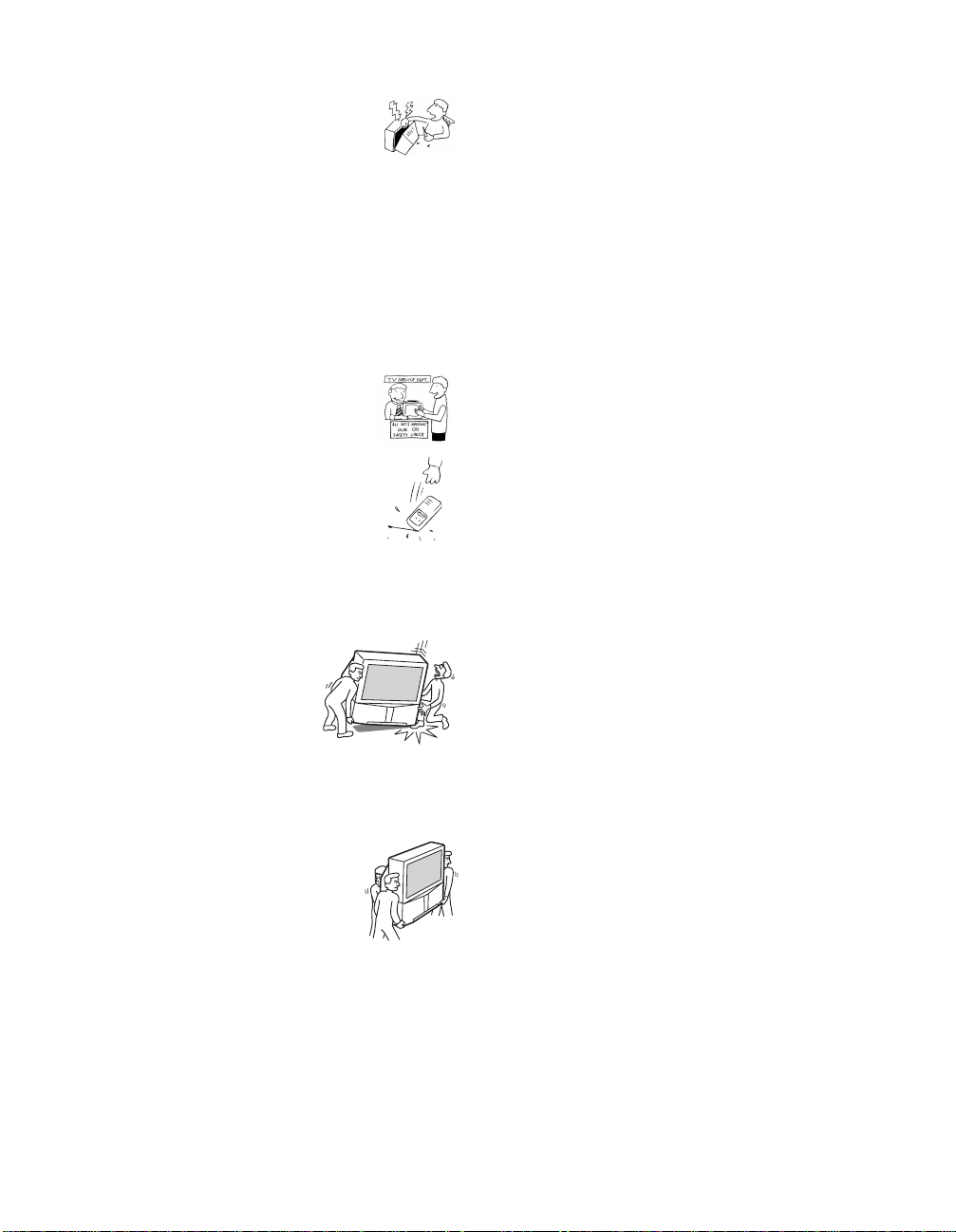
Carrying Your LCD Projection TV
Carrying the LCD projection TV requires at least four people. Do not grasp
the pedestal or the front panel of the LCD projection TV, otherwise these
parts migh t break off.
When moving the LCD projection TV, support the screen bottom with one
hand while grasping the top part with the other hand, as shown in the
illustration below.
Do not grasp the
pedestal or the front
panel of the LCD
projection TV.
AB
A
A
BB
18
Page 19

Installing and Connecting the LCD Projection TV
To Prevent the LCD Projection TV from Falling Down
Pay special attention to children around the LCD projection TV. If children
should climb onto or push the LCD projection TV or its stand SU-GW3 (not
supplied), it may fall down.
When Installing Your LCD Projection TV Against a Wall
Keep your LCD projection TV at least 10 cm (4 inches) from the wall.
Installing and Connecting the LCD Projection TV
19
Page 20

Installing and Connecting the LCD Projection TV
65
65
min. X.X m (approx. X ft.)
70"
min. X.X m (approx. X ft.)
60"
60"
70"
min.
X.X
m (approx.
ft.)
min. X.X m (approx. X ft.)
Recommended Viewing Area
The picture quality may be affected by your viewing position.
For the best picture quality , ins tall your LC D projection TV within the areas
shown below.
Sit at least 2.2 m (approx. 7 ft. ) for KD F -60 XBR9 50 or 2.6 m (ap pro x. 8 ft .)
for KDF-70XBR950 away from your LCD projection TV, and within 60° of
the vertical viewing area, and 130° of the horizontal viewing area.
Horizontal Viewing
Area
65
˚
65
˚
min. X.X m (approx. X ft.)
min. 2.6 m (approx. 8 ft.)
min. X.X m (approx. X ft.)
min. 2.2 m (approx. 7 ft.)
60"
60"
65
˚
65
˚
70"
70"
Vertical Viewing
Area
20
min. X.X m (approx. X ft.)
min. 2.6 m (approx. 8 ft.)
70"
X.X
2.2
m (approx.
m (approx.
60"
60"
70"
30˚
30˚
7
X
ft.)
ft.)
min.
min.
Page 21

Installing and Connecting the LCD Projection TV
LCD Projection TV Controls and Connectors
Front Panel Menu
Controls
The front panel menu controls allow access to the on-screen menus without
using the remote control. Pressing
MENU brings up the on-screen menus.
The arrow buttons move the on-screen cursor in the menus and by pressing
the button selects the menu item.
i.LINK
S VIDEO
VIDEO 2 IN
VIDEO
(MONO)
L–AUDIO–R
MENU TV/VIDEO
How to open and close the front panel
To open
VOL CH
Installing and Connecting the LCD Projection TV
Push and release.
To close
PRO
POWER
(Continued)
21
Page 22
Installing and Connecting the LCD Projection TV
Item Description
1 Memory Stick slot Memory Stick insertion slot. For details, see “Inserting
2 Memory Stick
indicator
3 POWER Press to turn on and off the LCD projection TV.
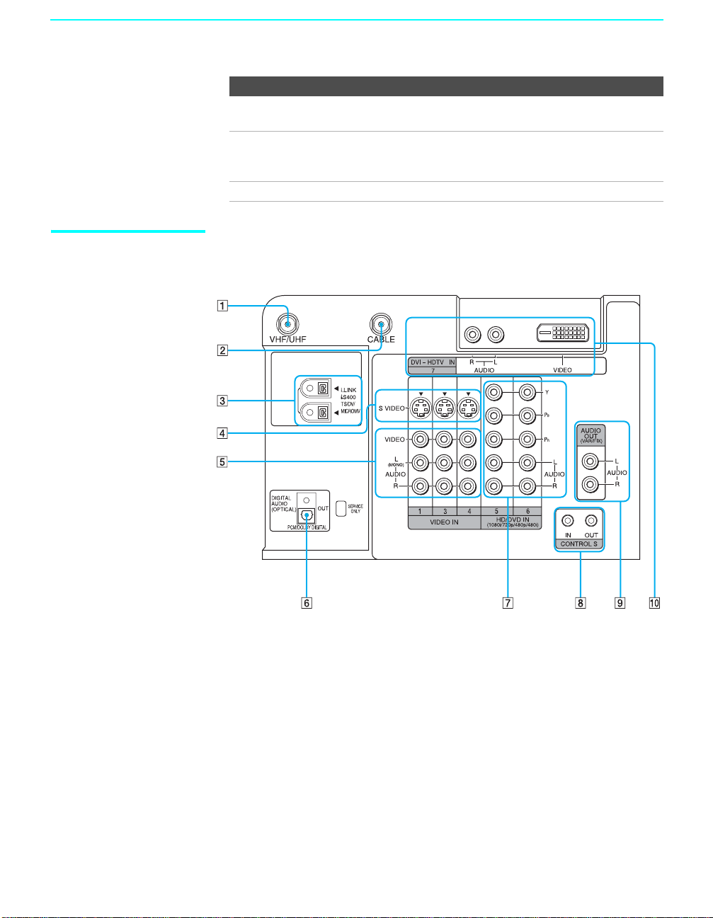
LCD Projection TV
Rear and Front
Panel Connectors
Rear of LCD projection TV
and Removing a Memory Stick” on page 66.
When lit, indicates that the Memory Stick is being read.
(Do not remove the Memory Stick when the indicator is
lit.)
22
Page 23
Installing and Connecting the LCD Projection TV
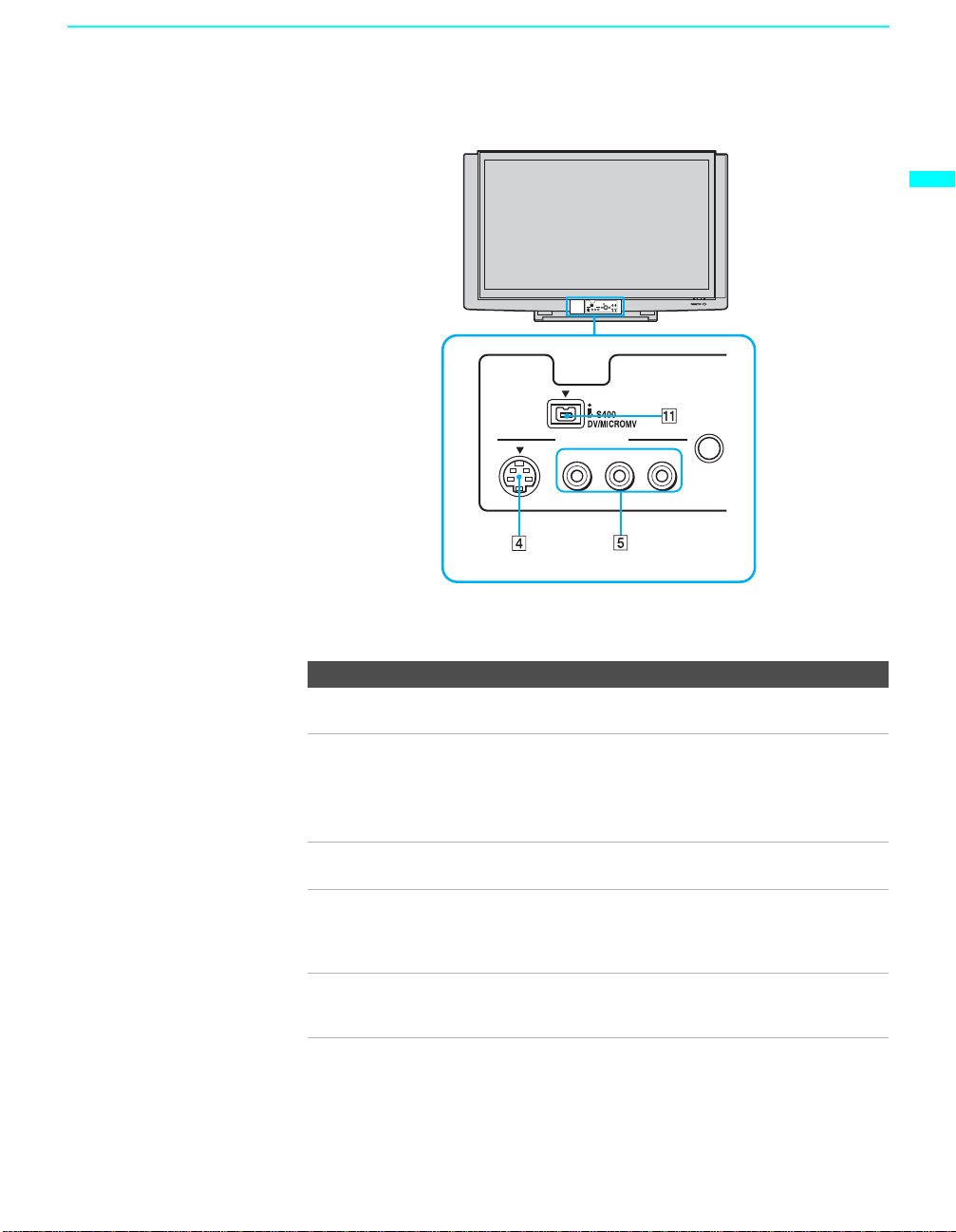
Front Panel of LCD projection TV
Installing and Connecting the LCD Projection TV
S VIDEO
Front panel connectors are in the control panel
cover. To open and close the cover, refer to page 21.
VIDEO 2 IN
VIDEO
(MONO)
L–AUDIO–R
MENU
Connection Description
1 VHF/UHF Connects to your VHF/UHF antenna or cable box output
jack.
2 CABLE Connects to your cable signal. This CABLE input jack, in
conjunction with the VHF/UHF input jack, lets you set up
your LCD project ion TV to switch between scrambled
channels (coming through a cable box) and unscrambled
cable channels. For details , see page 28.
3 i.LINK Connects to i.LINK-compatibl e devices. These terminals
are not intended for connection with person al compu ter s.
4 S VIDEO
(Front and rear)
Connects to the S VIDEO OUT jack of your VCR or other
S VIDEO-equipped video co mponent. Provides better
picture quality than the VHF/UHF j acks or the Video IN
jack.
5 VIDEO/
(L/R) AUDIO
(Front and rear)
Connects to the audio and video OUT jacks on yo ur VCR
or other video component. A fourth video input (VIDEO 2)
is located on the f ront panel of the LCD pro jection TV.
(Continued)
23
Page 24

Installing and Connecting the LCD Projection TV
Connection Description
6 DIGITAL AUDIO
(OPTICAL) OUT
(PCM/DOLBY*
DIGITAL)
7 HD/DVD IN (1080i/
720p/480p/480i)
8 CONTROL S
IN/OUT
9 AUDIO OUT
(VAR/FIX)
L/R
Connects to the optical audio input of a digital audio
component that is PCM/Dolby digital com patib le .
Connects to your DVD player’s or Digital Set-top box’s
component video (Y, P
B, PR) and audio (L/R) jacks.
To control other Sony equipment with the LCD projection
TV's remote control, connect the CONTROL S IN jack of
the equipment to the CONTR OL S OUT jack on the LCD
projection TV with the CONTROL S cable.
To control the LCD projection TV with a r e mote control
for another Sony product, connect the CONTROL S OUT
jack of the equipment to the CONTROL S IN jack on the
LCD projection TV with the CONTROL S cable.
Connects to the le ft an d ri g h t audio inputs of y ou r au dio or
video compone n t.
0 DVI-HDTV VIDEO
AUDIO L/R
(VIDEO 7 IN)
Can accommodate a copy-protected digital connection
**
(HDCP
) to other devices (such as digital set-top boxes)
that have compatible interfaces. The DVI-HDTV input
terminal is compliant with the E IA-86 1 stan da rd a n d is n ot
intended for use with personal computers. See the
instruction manual that came with your equipment for
details about connecting and using it with the LCD
projection TV.
qa i.LINK Connects to the i.LINK jack on your i.LINK-compatible
portable device. Provides a secure digital connection
between your LCD projection TV and your i.LINKcompatible portable device.
*
“Dolby”, “Pro Logic”, an d the double-D symbol are trademarks of Dolby
Laboratories.
**
High-bandwidth Digital Content Protection
24
Page 25

Installing and Connecting the LCD Projection TV
Basic Connections: Connecting a Cable or Antenna
The way in which you will connect your LCD projection TV varies,
depending on how your home receives a signal (cable, cable box, antenna)
and whether or not you plan to connect a VCR.
If You Are Connecting See Page
Cable or Antenna Only
❏ No cable box or VCR
Cable Box and Cable Only
❏ Cable box unscrambles only some channels
(usually premium channels)
❏ No VCR
Cable Box Only
❏ Cable box unscrambles all chann e ls
❏ No VCR
If you are connecting a VCR
❑
See the connections described on pages 32 and 33.
26
28
30
Installing and Connecting the LCD Projection TV
25
Page 26

Installing and Connecting the LCD Projection TV
Cable or Antenna
Only
For best results, use one of the following connections if you are
connecting a cable or an antenna and you:
❑ Do not need a cable box to unscramble channels. (If you have a cable
box, see pages 28 to 30.)
❑ Do not intend to connect a VCR. (If you have a VCR, see pages 32 and
33.)
The connection you choose depends on the cable type you have in your
home, as described bel ow.
75-ohm coaxial cable (usually found in newer homes)
Cable Type Connect As Shown
VHF Only or
combined VHF/
UHF
Cable
300-ohm twin lead cable (usually found in older homes)
Cable Type Connect As Shown
VHF Only or
UHF Only or
combined
VHF/UHF
75-ohm coaxial
cable
75-ohm coaxial
cable
300-ohm twin lead cable
Rear of LCD
projection TV
VHF/UHF
Rear of LCD
projection TV
CABLE
Rear of LCD projection TV
VHF/UHF
26
Antenna conn ector
(not supplied)
75-ohm coaxial and 300-ohm twin lead cable (found in some homes)
Cable Type Connect As Shown
VHF and UHF
75-ohm coaxial cable
Rear of LCD
projection TV
VHF/UHF
300-ohm twin lead cable
U/V mixer
(not supplied)
Page 27

Installing and Connecting the LCD Projection TV
Notes on Using This Connection
To Do This ... Do This ...
Switch the TV’s input between
the cable and antenna
Press ANT to switch back and forth between the
TV’s VHF/UHF and CABLE inputs.
✍ It is highly recommended to connect the antenn a using a 75-ohm coaxial
cable to get optimum picture quality. A 300-ohm twin lead cable can be
easily affected by radio noise and the like, resulting in signal
deterioration. If you use a 300-ohm twin lead cable, keep it away as far
as possible from the LCD projection TV.
✍ Do not use an indoor antenna because it is especially susceptible to
radio noise.
Installing and Connecting the LCD Projection TV
27
Page 28
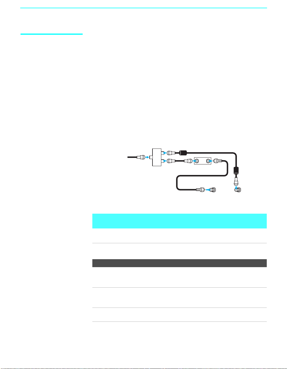
Installing and Connecting the LCD Projection TV
Cable Box and Cable
Only
For best results, use this connection if:
❑
Your cable company scrambles some channels, such as premium
channels (which requires yo u to us e a cable box), but does not scramble
all channels.
❑ You do not have a VCR. (If you have a VCR, see pages 32 and 33.)
With this connection you can:
❑
Use the LCD projection TV remote control to change channels coming
through the cable b ox to the LC D projecti on TV’s VHF/ UHF input jack.
(You must first program the remote control for your specific cable box;
see “Programming the Remote Control” on page 48.)
❑ Use the LCD projection TV remote control to change channels coming
directly into the LCD projection TV’s CABLE input. (The LCD
projection TV’s tuner provides a better signal than the cable box.)
CATV cable
Splitter
Coaxial
cable
Coaxial cable
Coaxial cable
IN OUT
Cable box
VHF/UHF
Rear of LCD projection TV
CABLE
28
About Using This Connection with Dual Picture (Twin View, etc.)
Features
With this connection, you can use all the dual picture features for unscrambled
channels coming directly into the LCD projection TV’s CABLE input jack.
Notes on Using This Connection
To Do This ... Do This ...
Use the cable box Tune the LCD projection TV to the channel the
cable box is set to (usually channel 3 or 4) and
then use the cable box to switch channels.
Set up the LCD projection TV
remote control to operate the
Program the remote control. See “Programming
the Remote Control” on page 48.
cable box
Activate the remote control to
operate the cable box
Press FUNCTION repeatedly until the SAT/
CABLE indicator lights up.
Page 29

Installing and Connecting the LCD Projection TV
Prevent the accidental switching
of TV channels
Switch the LCD projection TV’s
input between the cable box and
cable
When using the cabl e box, you need the LCD
projection TV to stay on the ch annel the cable
box is set to (usually channel 3 or 4). You can
use the LCD projection TV’s Channel Fix
feature to lock in a specific channel. For details,
see “Using the Channel Menu” on page 96.
Press ANT to switch back and forth between the
LCD projection TV’s VHF/UHF (scrambled
channels) and CABLE (unscrambled) inputs.
Installing and Connecting the LCD Projection TV
29
Page 30

Installing and Connecting the LCD Projection TV
Cable Box Only For best results, use this connection if:
❑
Your cable company scram bles al l channels, wh ich requi res you to use a
cable box.
❑ You do not have a VCR. (If you have a VCR, see pages 32 and 33.)
With this connection you can:
❑
Use the LCD projection TV remote control to change channels coming
through the cable box to the LCD projection TV’s VHF/UHF jack. (You
must first program the remote control for your specific cable box.)
About Using This Connection with Dual Picture (Twin View, etc.)
Features
With this connection, all channels come into the LCD projection TV through your
cable box and only one unscrambled signal is sent to the LCD projection TV , so you
cannot use the dual picture features. If some of your channels are scrambled, but
others are not, consider using the “Cable Box and Cable Only” connection on page
28 instead.
To connect the cable box
1 Connect the CATV cable to the cable box’s input jack.
2 Use a coaxial cable to connect the cable box’s output jack to the LCD
projection TV’s VHF/UHF jack.
30
3 Run the Auto Setup program, as described in “Setting Up the LCD
Projection TV Automatically” on page 45.
CATV cable
IN
Cable box
Notes on Using This Connection
To do this... Do This ...
Use the cable box Tune the LCD projection TV to the channel the cable box
Set up the LCD
projection TV remote
control to operate the
cable box
Coaxial cable
OUT
is set to (usually channel 3 or 4) and then use the cable box
to switch channels.
Program the remote control. See “Programming the
Remote Contro l” on pages 48.
VHF/UHF
Rear of LCD projection TV
Page 31

Installing and Connecting the LCD Projection TV
Activate the remote
control to operate the
cable box
Prevent the accidental
switching of TV
channels
Press FUNCTION repeatedly until the SAT/CABLE
indicator lights up.
When using the cable box, you need the LCD projection
TV to stay on the channel the cab le box is set to (usually
channel 3 or 4). You can use the LCD projection TV’s
Channel Fix feature to lock in a speci fic channel. For
details, see “Using the Channel Menu” on page 96.
Installing and Connecting the LCD Projection TV
31
Page 32

Installing and Connecting the LCD Projection TV
Connecting a VCR and Cable
Use this hookup if:
❑ You have cable TV that does not require a cable box.
Disconnect all power sources before making any connections.
1 Connect the cable TV cable to the VCR’s IN jack.
2 Using a coaxial cable, connect the VCR’s OUT jack to the LCD
projection TV’s CABLE jack.
3 Using AUDIO and S VIDEO cables, connect the VCR’s Audio and
S Video OUT jacks to the LCD projection TV’s AUDIO and S VIDEO
IN jacks.
Rear of LCD projection TV
S VIDEO
Coaxial cable
VIDEO (yellow)
AUDIO-L (white)
AUDIO-R (red)
VC-810S/
820S/830S
(not supplied)
S video cable (not supplied)
VCR
Cable
✍ If your VCR is not equipped with S VIDEO, use a VIDEO cable (yellow)
instead of the S VIDEO cable.
32
Page 33

Connecting a VCR and Cable Box
Use this hookup if:
Installing and Connecting the LCD Projection TV
❑ Your cable TV company scrambles some channels, but not all of them
(pay channels vs. regular cable channels) and you need to use a cable
box, and
❑ You want to enjoy the Twin View feature.
With this setup you can:
❑ Use the LCD projection TV remote control to change channels on your
cable box when the signal is scrambled. To program your Sony remote
control to operate your cable box, see “Programming the Remote
Control” on page 48.
❑ Use the LCD projection TV remote control to change channels using
your LCD projection TV when the signal is not scrambled. Your LCD
projection TV’s tuner provides a better signal than the cable box.
❑ Use the Twin View feature. (When all channels are routed through your
cable box, only one signal is sent to the LCD projection TV, so you
cannot use the Twin View feature.)
Disconnect all power sources before making any connections.
1 Connect the CATV cable to the single (input) jack of the splitter.
2 Use a coaxial cable to connect one of the splitter’s two output jacks to
the TV’s CABLE jack.
3 Use a coaxial cable to connect the splitter’s other output jack to the
cable box’s input jack.
Installing and Connecting the LCD Projection TV
4 Use a coaxial cable to connect the cable box’s output jack to the VCR’s
RF input jack.
5 Use an A/V cable to connect the VCR’s A/V output jacks to the LCD
projection TV’s A/V input jacks.
6 Use a coaxial cable to connect the VCR’s RF output jack to the LCD
projection TV’s VHF/UHF jack.
7 Run the Auto Setup program, as described in “Setting Up the LCD
Projection TV Automatically” on page 45.
✍ To view scrambled channels, set your LCD projection TV to channel 3 or
4 (depending on your cable box output). Change channels using your
cable box.
(Continued)
33
Page 34

Installing and Connecting the LCD Projection TV
Rear of LCD
projection TV
Splitter
S VIDEO
Coaxial cable
VIDEO (yellow)
AUDIO-L (white)
AUDIO-R (red)
If you are connecting a digital cable
box, you will need a special bidirectional splitter designed to work
with your cable box.
Coaxial
cable
VCR
34
CATV
cable
VC-810S/820S/
830S (not supplied)
S video cable
(not supplied)
Cable box
Coaxial
cable
✍ If your VCR is not equipped with S VIDEO, use a VIDEO cable (yellow)
instead of the S VIDEO cable.
✍ You will not be able to change channels on the VCR. Set your LCD
projection TV and VCR to channel 3 or 4, depending on your cable box
channel output.
✍ Pressing ANT on the remote control switches between the channels
coming in through the cable box (scrambled) and those coming directly
to the LCD projection TV (unscrambled).
Page 35

Installing and Connecting the LCD Projection TV
Connecting Two VCRs for Ta pe Editing
If you connect two VCRs, you can record from one VCR to the other while
using your LCD projection TV to monitor what is being recorded.
Disconnect all power sources before making any connections.
1 Using AUDIO and VIDEO cables, connect the playback VCR’s Audio
and Video OUT jacks to the recording VCR’s Audio and Video IN
jacks.
2 Using AUDIO and VIDEO cables, connect the recording VCR’s Audio
and Video OUT jacks to the LCD projection TV’s AUDIO and VIDEO
IN jacks.
Installing and Connecting the LCD Projection TV
Rear of LCD projection TV
VCR (playback)
VC-810S/820S/830S (not supplied)
✍ To perform tape editing, set the LCD projection TV to the video input
✍ You may need to change the video input on your VCR. Consult your
✍ If your VCRs have an S VIDEO jack: For best picture quality, use an
VCR (recording)
AUDIO-R (red)
AUDIO-L (white)
VIDEO (yellow)
VC-810S/820S/830S (not supplied)
intended for playback by pressing TV/VIDEO on the remote control.
VCR’s operating manual for instructions.
S VIDEO connection instead of the yellow video cable on your combined
A/V cable.
Using an S VIDEO cable, connect the playback VCR’s S VIDEO OUT jack
to the recording VCR’ s S VIDEO IN j ack. S VIDEO does not provide audio,
so audio cables must be connected to provide sound.
✍ You cannot record signals from equipment connected to the Y, PB, PR
input.
35
Page 36

Installing and Connecting the LCD Projection TV
Connecting a Satellite Receiver
Disconnect all power sources before making any connections.
1 Connect the satellite antenna cable to the satellite receiver’s
SATELLITE IN jack.
2 Using AUDIO and S VIDEO cables, connect the satellite receiver’s
AUDIO and S VIDEO OUT jacks to the LCD projection TV’s AUDIO
and S VIDEO IN jacks.
3 Connect a coaxial cable from your cable or antenna to the LCD
projection TV’s VHF/UHF or CABLE jack.
✍ If your satellite receiver is not equipped with S VIDEO, use a VIDEO cable
(yellow) instead of the S VIDEO cable.
Rear of LCD project ion TV
Coaxial
cable
36
S VIDEO
VIDEO (yellow)
AUDIO-L (white)
AUDIO-R (red)
VC-810S/820S/830S (not supplied)
S video cable (not supplied)
Satellite receiver
Satellite
antenna
cable
Page 37

Installing and Connecting the LCD Projection TV
Connecting a Satellite Receiver with a VCR
Disconnect all power sources before making any connections.
1 Connect the satellite antenna cable to the satellite receiver’s
SATELLITE IN jack.
2 Connect the CATV cable to the VCR’s VHF/UHF IN jack.
3 Using a coaxial cable, connect the VCR’s VHF/UHF OUT jack to the
LCD projection TV’s CABLE jack.
4 Using AUDIO and S VIDEO cables, connect the satellite receiver’s
AUDIO and S VIDEO OUT jacks to the VCR’s AUDIO and S VIDEO
IN jacks.
5 Using AUDIO and S VIDEO cables, connect the VCR’s AUDIO and S
VIDEO OUT jacks to the LCD projection TV’s AUDIO and S VIDEO
IN jacks.
Rear of LCD projection TV
Satellite receiver
Satellite
antenna
cable
Installing and Connecting the LCD Projection TV
AUDIO-R (red)
AUDIO-L (white)
VIDEO (yellow)
VC-810S/820S/830S
(not supplie d )
S VIDEO
Coaxial cable
CATV Cable
S video cable (not supplied)
S video cable
(not supplied)
VCR
VC-810S/
820S/830S
(not
supplied)
(Continued)
37
Page 38

Installing and Connecting the LCD Projection TV
✍ Be sure your VCR’s video input is set correctly. Consult your VCR’s
operating manual for instructions.
✍ Use TV/VIDEO to select
- VIDEO 1 to watch satellite TV or the VCR (your VCR m ust be turned on ).
- VHF/UHF to watch cable TV.
✍ If your VCR or satellite receiver is not equipped with S VIDEO, use a
VIDEO cable (yellow) instead of the S VIDEO cable.
38
Page 39

Connecting an Audio Receiver
Disconnect all power sources before making any connections.
Using audio cables, connect the LCD projection TV’s AUDIO OUT (VAR/
FIX) jacks to the audio receiver’s audio LINE IN jacks.
Rear of LCD projection TV
Installing and Connecting the LCD Projection TV
Installing and Connecting the LCD Projection TV
AUDIO-L (white)
RK-C310/C320/C330
(not supplied)
Line
input
AUDIO-R
(red)
39
Page 40

Installing and Connecting the LCD Projection TV
Connecting a DVD Player with Component Video Connectors
This is the preferred hookup to use if:
❑ Your DVD player has component (Y, B-Y, R-Y) jacks.
Disconnect all power sources before making any connections.
1 Using three separate component vi deo cables, connect th e D VD player’s
Y, B-Y and R-Y jacks to the Y, P
TV. Use the HD/DVD IN 5 or 6 connections.
✍ The Y, B-Y and R-Y jacks on your DVD player are sometimes labeled
Y, C
B and CR, or Y, PB and PR. If so, connect the cables to like colors.
B and PR jacks on the LCD projection
2 Using an audio cable, connect the DVD player’s Audio OUT jacks to
the LCD projection TV’s AUDIO IN jack s. Be sure to u se the sa me r ow
of inputs that you used for the video connection (HD/DVD IN 5 or 6).
Rear of LCD projection TV
DVD pl ayer
VMC-10 (not supplied)
AUDIO-L (white)
RK-C310/C320/C330 (not supplied)
Y
P
B
PR
AUDIO-R (red)
✍ To take advantage of the Wide Screen modes, set the TV’s aspect
ratio to 16:9 on your DVD player. For details, refer to the operating
instructions supplied with your DVD player.
40
Page 41

Installing and Connecting the LCD Projection TV
Connecting a DVD Player with A/V Connectors
Use this hookup if:
DVD player
❑ Your DVD player does not have component (Y, PB, PR) jacks.
✍ If your DVD player has video component output connectors: for best
picture quality use the connection described on page 40.
Disconnect all power sources before making any connections.
1 Using audio cables, connect the DVD player’s Audio OUT jacks to the
LCD projection TV’s AUDIO IN jacks.
2 Using an S VIDEO cable, connect the DVD player’s S VIDEO jack to
the LCD projection TV’s S VIDEO jack.
Rear of LCD projection TV
S video cable
(not supplied)
S VIDEO
Installing and Connecting the LCD Projection TV
AUDIO-R (red)
AUDIO-L (white)
RK-C310/C320/C330 (not supplied)
✍ T o take adva ntage of the Wide Screen modes, set the T V’s aspect ratio to
16:9 on your DVD player. For details, refer to the operating instructions
supplied with your DVD player.
✍ Use TV/VIDEO on the remote control to switch between the VCR, DVD
player and cable TV inputs.
✍ If your VCR is not equipped with S VIDEO, use a VIDEO cable (yellow)
instead of the S VIDEO cable.
41
Page 42

Installing and Connecting the LCD Projection TV
Connecting a Camcorder
For easy connection of the camcorder, the LCD projection TV has front
Audio and Video inputs (shown belo w). Howeve r, if you prefer, you can al so
connect the camcorder to the LCD projection TV’s rear AUDIO and VIDEO
IN jacks.
Using AUDIO and S VIDEO cables, connect the camcorder’s Audio and
S VIDEO OUT jacks to the LCD projection TV’s AUDIO and S VIDEO IN
jacks.
✍ If you have a mono camcorder, connect its left audio output to the LCD
projection TV’s AUDIO L (MONO) jack.
✍ If your camcorder is not equipped with S VIDEO, use a VIDEO cable
(yellow) instead of the S VIDEO cable.
42
S VIDEO
VIDEO 2 IN
VIDEO
(MONO)
L–AUDIO–R
MENU
AUDIO-R (red)
AUDIO-L (white)
VIDEO (yellow)
S VIDEO
A/V output
VC-810S/820S/830S
(not supplied)
S video cable (not supplied)
Page 43

Installing and Connecting the LCD Projection TV
Connecting a Device with an Optical IN Connector
You can use the LCD Projection TV's DIGITAL AUDIO (OPTICAL) OUT
jack to connect a digital audio device that is PCM/Dolby digital compatible,
such as an audio amplifier.
Using an optical cable, connect the device's OPTICAL IN jack to the LCD
Projection TV's DIGITAL AUDIO (OPTICAL) OUT jack.
Rear of LCD projection TV
Installing and Connecting the LCD Projection TV
Optical cable
Audio amplifier
LINE
OUT
L AUDIO R
LINE
IN
The DIGITAL AUDIO
(OPTICAL) OUT jack is
available only when a digital
TV channel is received.
OPTICAL
IN
43
Page 44

Installing and Connecting the LCD Projection TV
Using the CONTROL S Feature
CONTROL S allows you to control your LCD projection TV system and
other Sony equ ipment with one remote co ntrol. In addi tion to allowing you
to control multiple devices with one remote control, the CONTROL S
feature allows you to always point your remote control at your LCD
projection TV, instead of having to point it at the other equipment, which
might be hidden or out of direct line of sight.
Rear of LCD project i on TV
44
Page 45

Installing and Connecting the LCD Projection TV
Setting Up the LCD Projection TV Automatically
After you finish connecting your LCD projection TV, you need to run Auto
Setup to set up available analog and digital channels. The Auto Program
screen appears when you turn your LCD projection TV on for the first time
after installing it. If you do not want to set up the channels at this time, you
can do it later by using the Auto Program feature in the Channel menu (see
page 96).
✍ The Auto Setup feature does not apply for installations that use a cable
box for all channel selection.
Using Auto Setup 1 Press POWER on the front panel of your LCD projection TV to t urn o n
the LCD projection TV.
The Initial Setup screen appears.
2 Move the arrow button up or down to select the desired on-screen
display language, and press the button.
“Start auto program now?” appears.
3 Move the arrow button up or down to select “Yes,” and press the
button.
Auto Program automatically creates a list of receivable channels.
Installing and Connecting the LCD Projection TV
✍ Auto Program may take up to 30 minutes to complete. A progress bar is
displayed while the channel list is being created.
i-LINK
VIDEO 2 IN
VOL CH
S VIDEO
VIDEO L–AUDIO–R
LCD projection
TV front panel
MENU TV/VIDEO
i.LINK
MENU TV/VIDEO
POWER
VOL CH
✍ You can run Auto Program by selecting it in the Channel menu, as
described on page 96.
45
Page 46

Using the Features
Using the Remote Control
The following table describes the buttons on the remote control that are for
more advanced functions.
Button Descriptions
Button Description
1 MUTING Press to mute the sound. Press again or press VOL + to restore
2 FUNCTION Press repeatedly until the indicator of the equipment (TV,
3 Press repeatedly to step through the available audio effect
4 SLEEP Press repeatedly until the TV displays the time in minutes (15 ,
5 GUIDE Press to display the digital program guide.
6 Use with 0-9 and ENTER buttons to select digital channels
7 PICTURE Press repeatedly to step through the available video picture
8 WIDE Press to step through the wide screen modes: Wide Zoom,
9 V/v/B/b
X/x/m/M
RM-Y1000
q; H: Playback
qa Turns on/off Twin View. For details, see “Using Twin
the sound.
SAT/CABLE, DVD/VCR, i.LINK) that you want to operate
lights up.
modes: Virtual Dolby, TruSurround, Simulated, Off.
For details, see “Sele c tin g Au d i o Op tio ns ” on pag e 92 .
30, 45, 60 or 90) that you want the LCD projection TV to
remain on before shutting off. To cancel Sleep Timer, press
SLEEP repeatedly until SLEEP OFF appears.
If FUNCTION is switched on SAT/CABLE
Press to display the progr am guid e of yo ur s atellite program
provider.
(for example, 2.1). For details on selecting digital channels,
see page 60.
modes: V ivi d, Stand ard, Pro. Also available in the Video
menu. For details , see “Selecting Video Options” on page 88.
Normal, Full and Zoom. For details, se e “ U sing Wide Sc ree n
Mode” on page 59.
When the menu is displayed, move the on-screen cursor.
X: Pause
x: Stop
m: Rewind
M: Fast-Forward
: When the menu is displayed, select the item.
View™” on page 55.
46
Page 47

Using the Features
Button Description
qs ANT
INDEX
qd VOL +/– Adjusts the volume.
qf POWER
buttons
(Green)
qg REC
RESET
qh TV/VIDEO
qj DISPLAY Press once to display the current time and channel label (if set)
qk JUMP Press to jump back and forth between two channels. The LCD
ql 0 – 9 and
ENTER
w; FAVORITES Displays the Favorite Channels list. For details, see “Using
wa FREEZE Freezes the window picture. Press again to restore the picture.
ws i.LINK Press to display the i.LINK Control Panel. For information on
wd
MEMORY
STICK
wf MENU Press to display the LCD projection TV on-screen menu. Press
wg CH +/– Scan through channels.
wh EXIT Press to exit the on-screen menu or display and return to
Changes between the VHF/UHF input and the CABLE input.
If FUNCTION is switched on SAT/CABLE
Displays index of your satellite program provider.
Turn on and off the LCD projection TV and other audio/video
equipment you have pro gr a m med into the r emote control. For
instructions, see “Programming the Remote Control” on page
48.
Record
Press when in a menu to reset the settings to the factory
defaults.
Cycles through the video equipment connected to your
projection TV
VIDEO 3, VIDEO 4, VIDEO 5, VIDEO 6
and channel number. Press again to turn Display off. See page
104 for details on setting the time.
projection TV alternates between the current channel and t he
last channel that was select ed.
Press 0 - 9 to select a channel, the channel changes aft er 3
seconds. Press ENTER to select immediately.
Favorite Channels” on page 54.
using the i.LINK Control Panel, see page 83.
Press to display the Memory Stick Menu.
For details, see “Using the Memory Stick Viewer” on page 64.
again to exit from the menu.
To scan rapidly through the cha nn els, press and hol d
z
down CH+ or CH–.
normal viewin g.
’s video inputs: TV,
VIDEO 1, VIDEO 2
and
LCD
,
VIDEO 7
.
Using the Features
47
Page 48

Using the Features
Programming the Remote Control
The remote control is preset to operate Sony brand video equipment.
Function Equipment Programmable Code
DVD/VCR Sony DVD player 751
SAT/CABLE Sony DSS tuner 801
i.LINK Sony DVD player (i.LINK) 901
If you have video equipment other than Sony brand that you want to control
with the LCD projection TV’s remote control, use the following procedure
to program the remote control.
✍ The equipment must have infrared (IR) remote capability in order to be
used with the remote control.
1 Turn to the list of “Manufacturer’s Codes” on page 49, and find the
three-digit code number for the manufacturer of your equipment. (If
more than one code number is listed, use the number listed first.)
2 Press FUNCTION repeatedly until the DVD/VCR, SAT/CABLE or
i.LINK indicator lights up.
3 Press SAT/CABLE for five seconds until the indicator of the selected
input flashes.
4 While the desired indicator is flashing, enter the three-digit
manufacturer’s code number.
5 Press ENTER.
Number
48
✍ You must do step 5 within 10 seconds of step 4, or you must redo
steps 4 through 5.
6 To check if the code number works, aim the LCD projection TV’s
remote control at the equipment and press POWER that corresponds
with that equipment. If it responds, you are done. If not, try using
another code listed for that manufacturer.
Notes
❑
If more than one code number is listed, try entering them one by one
until you come to the correct code for your equipment.
❑ If you enter a new code number, the code number you previously
entered at that setting is erased.
❑ In some cases, you may not be able to operate your equipment with the
supplied remote contr ol. In such cases, use the equi pm ent ’s own remote
control unit.
❑ Whenever you remove the batteries to replace them, the code numbers
may revert to the factory setting and must be reset.
Page 49

Using the Features
Manufacturer’s Codes
VCRs
Manufacturer Code
Sony 301, 302, 303
Admiral
(M. W a rd)
Aiwa 338, 344
Audio Dynamic 314, 337
Broksonic 319, 317
Canon 309, 308
Citizen 332
Craig 302, 332
Criterion 315
Curtis Mathes 304, 338, 309
Daewoo 341, 312, 309
DBX 314, 336, 337
Dimensia 304
Emerson 319, 320, 316 ,
Fisher 330, 335
Funai 338
General Electric 329, 304, 309
Go Video 322, 339, 340
Goldstar 332
Hitachi 306, 304, 305,
Instant Replay 309, 308
JC Penney 309, 305, 304,
JVC 314, 336, 337,
Kenwood 314, 336, 332,
LG 332
LXI (Sears) 332, 305, 330,
Magnavox 308, 309, 310
Marantz 314, 336, 337
Marta 332
Memorex 309, 335
Minolta 305, 304
Mitsubishi/
MGA
Multitech 325, 338, 321
NEC 314, 336, 337
Olympic 309, 308
Optimus 327
Orion 317
327
317, 318, 341
338
330, 314, 336,
337
345, 346, 347
337
335, 338
323, 324, 325,
326
Manufacturer Code
Panasonic 308, 309, 306,
Pentax 305, 304
Philco 308, 309
Philips 308, 309, 310
Pioneer 308
Quasar 308, 309, 306
RCA/
PROSCAN
Realistic 309, 330, 328,
Sansui 314
Samsung 322, 313, 321
Sanyo 330, 335
Scott 312, 313, 321,
Sharp 327, 328
Signature 2000
(M. Ward)
SV2000 338
Sylvania 308, 30 9, 338,
Symphonic 338
Tashiro 332
Tatung 314, 336, 337
Teac 314, 336, 338,
Technics 309, 308
Toshiba 312 , 311
Wards 327, 328, 335,
Yamaha 314, 330, 336,
Zenith 331
Laserdisc Pl ayers
Manufacturer Code
Sony 701
Panasonic 704, 710
Pioneer 702
DVD Players
Manufacturer Code
Sony 751
Sony (i.LINK) 901
General Electric 755
Hitachi 758
JVC 756
307
304, 305, 308,
309, 311, 312,
313, 310, 329
335, 324, 338
335, 323, 324,
325, 326
338, 327
310
337
331, 332
337
Magnavox 757
Mitsubishi 761
Oritron 759
Panasonic 753
Philips 757
Pioneer 752
RCA/Proscan 755
Samsung 758
Toshiba 754
Zenith 760
Cable Boxes
Manufacturer Code
Sony 230
Hamlin/Regal 222, 223, 224,
Jerrold/G. I. 201, 202, 203,
Oak 227, 228, 229
Panasonic 219, 220, 221
Pioneer 214, 215
Scientific Atl a nta 209, 210, 211
Tocom 216, 217
Zenith 212, 213
Satellite Receivers
Manufacturer Code
Sony 801
Dish Network 810
Echostar 810
General Electric 802
Hitachi 805
Hughes 804
Mitsubishi 809
Panasonic 803
RCA/
PROSCAN
Toshiba 806, 807
225, 226
204, 205, 206,
207, 208, 218
802, 808
Using the Features
49
Page 50

Using the Features
Using Other Equipment with Your LCD Projection TV Remote Control
All Equipment
To Do This ... Do This ...
Switch the LCD projection TV’s
input to the VCR, DVD player, or
other connected equipment
Set up the LCD projection TV
remote control to operate no n-Sony
equipment
Operating a VCR
To Do This ... Press
Activate the remote control to
operate the VCR
Turn on/off SAT/CABLE
Change channels CH +/–
Record z REC
Play
Press TV/VIDEO repeatedly to cycle through
the video equipme nt co nn e cted to the LCD
projection TV’s video inputs.
You must program the remote control the first
time you use it. See “Programming the Remote
Control” on page 48.
FUNCTION repeatedly until the DVD/VCR
indicator lights up.
Operating a Satellite
Receiver
Stop x
Fast forward M
Rewind the tape m
Pause X
Search the picture forward or
backward
To Do This ... Press
Activate the remote control to
operate the satellite receiver
Turn on/off SAT/CABLE
Select a channel 0-9, ENTER
Change channels CH +/–
Back to previous channel JUMP
Display channel number DISPLAY
Display SAT Index INDEX
Display SAT Guide GUIDE
Display SAT Menu MENU
Move highlight (cursor) V v B b
Select item
M or m during playback
(release to resume normal playback)
FUNCTION repeatedly until the SAT/CABLE
indicator lights up.
50
Page 51

Operating a Cable
Box
Operating a DVD
Player
To Do This ... Press
Activate the remote control to
operate the cable box
Turn on/off SAT/CABLE
Select a channel 0-9, ENTER
Change channels CH +/–
Back to previous channel JUMP
To Do This ... Press
Activate the remote control to
operate the DVD
Turn on/off SAT/CABLE
Play
Stop x
Pause X
Step through different
tracks of the disc
Step through different chapters
of a video disc
FUNCTION repeatedly until the SAT/CABLE
indicator lights up.
FUNCTION repeatedly until the DVD/VCR
indicator lights up.
M to step forward or m to step backward
CH+ to step forward or CH– to step backward
Using the Features
Using the Features
Operating an MDP
(Laserdisc Player)
To Do This ... Press
Activate the remote control to
operate the MDP
Turn on/off SAT/CABLE
Play
Stop x
Pause X
Search the picture forward or
backward
Search a chapter forward or
backward
FUNCTION repeatedly until the indicator of the
position you programmed for the MDP player
lights up.
M or m during playback
(release to resume normal playback)
CH +/–
51
Page 52

Using the Features
Watching the TV
Many TV features can be accessed directly through the remote control. The
following will explain the function of some of the buttons found on your
remote control.
Buttons for LCD
Projection TV
Operations
1 FUNCTION
Press until the TV indicator lights up.
This activates the remote control for use with the LCD projection TV.
2 ANT
Press to change between the VHF/UHF input and the CABLE input.
3 POWER
Press to turn the LCD projection TV on and off. If a video input indication
(e.g., VIDEO 1, VIDEO 2) appears on the screen, press
CH +/ – until a channel number appears.
4 0-9, and ENTER
TV/VIDEO or
Use for direct channel selection. Press 0-9 to select an analog channel (for
example, to select channel 10, press 1 and 0). The channel will change after
3 seconds, or you can press ENTER for immediate selection.
For digital subchannels, press 0-9, , press 0-9 again, and then
ENTER.
You can also select digital channels using the digital program guide. See
z
page 60 for details.
5 CH +/–
Press to scan through the channels (+ up or – down).
6 VOL +/–
Press to adjust the volume (+ up or – down).
52
RM-Y1000
7 JUMP
Press to jump back and forth between the current channel and the last
channel selected.
8 MUTING
Press to mute the sound. “MUTING” will appear on the screen and will dim
three seconds later. To restore the sound, press again or press
9 FREEZE
VOL +.
This is useful when you need to copy down information that appears on the
LCD projection TV’s screen (see “Using the Freeze Function” on page 58).
Page 53

Using the Features
q; SLEEP
Press repeatedly to display the time in minutes (15, 30, 45, 60 or 90) that you
want the LCD projection TV to remain on before shutting off.
To cancel Sleep Timer, press SLEEP repeatedly until SLEEP OFF appears.
qa i.LINK
Press to display a list of available i.LINK devices, and select the desired
device from the list. See page 83 for details.
qs TV/VIDEO
Press repeatedly to scroll through available video inputs: TV, VIDEO 1,
VIDEO 2, VIDEO 3, VIDEO 4, VIDEO 5, VIDEO 6 and VIDEO 7.
Using the Features
RM-Y1000
If you select
Skip as a Video Label in the Setup menu, your LCD projection
TV will skip the video input you selected (see “Video Label” on page 103).
qd DISPLAY
Press to display the channel number, current time and channel label (if set).
To turn the display off, press
qf PICTURE
DISPLAY again.
Press PICTURE repeatedly to directly choose one of three different video
modes that best suits the program you are watching.
Vivid: Select for enhanced picture contrast and sharpness.
Standard: Select to display a standard picture for home entertainment.
Pro: Select to display a picture with minimum enhancements.
When you select each mode, you can also adjust the picture quality (such as
Picture, Brightness, Color, etc.) to suit your taste. For details, see “Mode”
on page 88.
53
Page 54

Using the Features
Using Favorite Channels
The Favorite Channel feature lets you select programs from a list of favorite
channels that you preset.
Creating a List of
Favorite Channels
Displaying a List of
Favorite Channels
1 Press MENU to display the Menu.
2 Press B or b to highlight the Channel icon and press .
3 Press to select Favorite Channels.
4 Press V or v to highlight a Favorite Channel number (1-16) and press
.
5 Press V or v to highlight a channel you want to assign to the Favorite
Channel number. A preview of the highlighted channel appears in the
upper right of the screen.
Press to select that channel as a Favorite Channel.
6 To add more channels to your favorites list, repeat steps 4-5.
To clear a Favorite Channel, press V or v to highlight the channel you
want to clear. Press and then press RESET.
7 Press MENU to exit the Menu.
For details on using the Channel Menu, see page 96.
z
1 Press FAVORITES.
The Favorite Channel options appear.
Preview window
54
Favorites
10 ABC
20 HBO
36 MTV
6 FOX
8 CBS
37 COMED
Exit
Favorite Channels
2 Press V or v to highlight the channel yo u want to wa tch. Th e program of
that channel appears in the preview window. Press to select.
✍ When the remote control mode is set to other than TV function, you can
display the Favorite Channels. However, you cannot select the channel
by using V or v.
To assign Channel Labels (e.g., ABC, HBO, MTV, etc.) to channel
z
numbers, as sho wn at right, use the Channel Label fea ture in the Ch annel
Menu (see pag e 97).
Page 55

Using Twin View™
Using the Features
Twin View enables you to watch two programs at the same time. You can
also change the size of both the left and right pictures.
Activating Twin
Pictures
Activating the
Picture
To display twin pictures
1 Make sure you r LCD projection TV is tuned to
a working channel.
2 Press .
To cancel twin pictures
Press again (or press ).
❑
Although two pictures appear on the screen at the same time, only one
picture is active. Change the picture size by using the V or v button. For an
active picture, you can:
❑ Change channels.
❑ Adjust the volume.
❑ Switch the input sources from VHF/UHF to cable by pressing ANT or
TV/VIDEO to switch the video input.
Using the Features
To activate the right picture
❑
Press b.
To activate the left picture
Press B.
❑
(Continued)
55
Page 56

Using the Features
✍ Hookups that affect your ability to use Twin View:
- If you are viewing all channels through the cable box, the Twin
View feature will not work. The cable box only unscrambles one
signal at a time, so the right picture will be the same as the left
picture.
- You can watch a scrambled cable channel and another video
source. Be sure your DVD player, VCR or satellite receiver are
connected to one of the VIDEO IN 1-7 and antenna inputs on the
rear of the LCD projection TV. Digital TV pictures, and pictures
from equipment connected to HD/DVD IN 5 and 6, and DVI-HDTV
IN 7, will only appear in the left picture, not in the right.
✍ The active picture is indicated by the 9 icon.
Factors Affecting Twin View
If you use a cable box to vie w all ch annels, the s ame ch annel ap pears in
❑
both windows because the cable box unscrambles only one channel at a
time.
❑ If you use a cable box , you can v iew the cable box output in one wi ndo w
and view a different source (such as a VCR or DVD player) in the
second window by using the TV/VIDEO button.
❑ Digital TV channels, as well as any sources connected to the VIDEO 5,
VIDEO 6, and VIDEO 7 inputs display in the left window, but not the
right.
❑ If you are viewing a 4:3 source and a 16:9 enhanced source (such as a
DVD) side by side, the 4:3 source appears larger.
❑ Twin View does not display channels that are blocked by parental
settings (see page 98).
56
Page 57

Using the Features
Changing the
Picture Size
The zoom feature lets you change the size of the left and right pictures.
To enlarge the left
picture (reduce the
right)
1 Press B to
activate the left
picture (if not
already
activated).
2 Press V to
enlarge the
picture and v to
reduce the
picture.
To enlarge the right
picture (reduce the
left)
1 Press b to
activate the right
picture (if not
already
activated).
2 Press V to enlarge
the picture and v
to reduce the
picture.
Using the Features
✍ When you adjust the twin screen sizes, the LCD projection TV memorizes
the change. The next time you use the Twin View function, the
memorized sizes appear.
57
Page 58

Using the Features
Using the Freeze Function
The FREEZE button allows you to temporarily capture a program’s picture.
You can use this feature to write down information such as phone numbers,
recipes, etc.
To use the Freeze function
1 When the program information you want to capture is displayed, press
FREEZE.
2 The LCD projection TV switches to Twin View mode and displays the
“frozen” picture on the right, while the current prog ram continues on the
left.
Current program
in progress
Freeze
Frozen picture
3 To cancel and return to normal viewing, press FREEZE.
✍ Freeze feature is not available if you are already in Favorite Channel (see
page 54), or Twin View™ (see page 55) mode.
58
Page 59

Using Wide Screen Mode
Wide Screen Mode lets you watch 4:3 normal broadcasts in several Wide
Screen Modes (16:9 aspect ratio).
❑ Press WIDE repeatedly to toggle through the following Screen Mode
settings.
z
You can also access the Screen Mode settings in the Screen menu.
For details, see page 94.
Using the Features
Using the Features
Wide Zoom enlarges the 4:3 picture to
fill the 16:9 screen, keeping the original
image as much as possible.
Normal returns the 4:3 picture to its
original size.
Full Mode stretches the 4:3 picture
horizontally only, to fill the 16:9 screen.
Zoom Mode enlarges the 4:3 picture
horizontally and vertically to an equal
aspect ratio that fills the 16:9 screen.
Useful for watching Letterbox movies.
z
When you change channels or inputs, the Screen Mode settings
revert to Wide Zoom (or the 4:3 Default setting in the Screen menu).
To ret ain the cu rrent Screen Mode setting as channe ls and in puts are
changed, set 4:3 Default to Off. For details, see page 95.
59
Page 60

Using the Digital Program Guide
Displaying the Digital Program Guide
This LCD projection TV is equipped to show digital programming, if a
digital signal is present. The digital program guide and menus let you review
program information, select digital channels and subchannels, set up your
LCD projection TV’s digital programming, and enable digital closed
captioning.
✍ Analog channels are not available in this guide.
To display the digital program guide:
1 Tune your LCD projection TV to a digital channel by using the 0-9,
, and
ENTER buttons.
2 Press GUIDE on the LCD projection TV’s remote control. The digital
program guide appears, with the currently selected program showing in
the background.
z
The digital program
guide and menus are
not available while
using multipicture
functions (Twin View,
Freez e, i. LINK, Me mory
Stick, or Favorite
Channels).
60
✍ Program information in the guide is provided by the broadcasters. As a
result, it may sometimes include only the channel number, without a
program title or description.
Page 61

Using the Digital Program Guide
Navigating the
Digital Program
Menus
Using the Guide
Menu
Four digital menus are available on the digital program guide.
Digital Program Menu See Page
Using the Guide Menu 61
Using the Program Options Menu 61
Using the Caption Vision Menu 62
Using the Digital Setup Menu 62
To navigate to these menus and through the available options:
1 Press V v B b to navigate through the options.
2 Press to select the desired option.
The Guide menu allows you to select di git al channel s and sub c hann els from
a dropdown list. This list also provides information about the current
program being shown on each digital channel.
Using the Digital Program Guide
Using the Program
Options Menu
✍ Subchannels are additional channels of programming broadcast
simultaneously. For example, channel 4 might include three subchannels
(4.1, 4.2, 4.3) that are showing programs at the same time.
The Program Options menu allows you to customize the settings of the
program on the currently tuned channel.
Option Description
Alternate
Video
Alternate
Audio
Each program has a main video stream, and may have alternate video
streams. This option allows yo u to switch a mon g thes e altern ate v ideo
streams.
Each program has a main audio stream (the audio that you hear when
the channel is first tuned). This option allows you to switch among
these alternate audio streams (e.g., for different languages).
61
Page 62

Using the Digital Program Guide
Using the Caption
Vision Menu
Using the Digital
Setup Menu
The Caption Vision menu allows you to turn on/off digital closed captioning,
and to modify how digital closed captioning is shown on your LCD
projection TV. Depending on the program, digital closed captioning will be
available in a number of different languages, aspect ratios, and reading
levels.
1 Press V or v to select from the following six services. The service
description, if available, applies to the currently tuned channel.
Option Description
Off Turns off closed captioning for digital programs
1 XXX YYY ZZZ XXX = language (English, Spanish, French, etc.)
2 XXX YYY ZZZ
3 XXX YYY ZZZ
4 XXX YYY ZZZ
5 XXX YYY ZZZ
6 XXX YYY ZZZ
✍ The Caption Vision menu only affects digital channels. For closed
captioning on analog channels, see “Using the Setup Menu” on page
102.
The Digital Setup menu lets you change the way your digital channels are
displayed.
The followi ng digital setup functions are available:
YYY = reader level (standard*, easy)
ZZZ = aspect ratio (4: 3, 16:9)
* When set to this option, the option name i s not shown
z
This option is the same
as the “Digital
Channels” option. See
“Using the Channel
Menu” on page 96.
62
Option Description
Add Digital
Channels
Channel Show/HideThis option allows you to remove (hide) digital channels from
Digital Signal
Strength
Digital Caption
Setup
This option allows you to add new digital channels for the
currently active antenna mode (Cable or VHF/UHF).
This option is useful if the number of dig ital channels that your
LCD projection TV is able to receive has recently been
increased, but you do not want your LCD projection TV to
perform a full Auto Setup.
the Digital Program Guide’s list of channels and subchannels,
as well as fr om chan nel sur f ing usin g CHANNEL +/–. Hidden
channels can still be directly tuned using 0-9 and .
Displays the current strength of the digital signal on VHF/
UHF, to allow you to adjust your antenna for optimal
reception. (Does not apply to digital cable channels.)
Allows you to customize digital closed captioning (see page
63 for details).
Page 63

Using the Digital Program Guide
Customizing
Caption Vision
You can use the Digital Caption Setup menu to customize your LCD
projection TV’s Caption Vision.
Select from the following options to change the visual characteristics of your
LCD projection TV’s digital closed capti oning. A preview window displays
a sample as you scroll through each option.
Option Description
Character Size Small, Standard*, Large
Character Style Style 1-7 (Style 4*)
Character Color None, Color 1-8 (White*)
Edge Type None*, Raised, Depressed, Outline, Left Shadow, Right
Shadow
Edge Color Color 1-8 (Black*)
Background
Color
Window Color None*, Color 1-8
None, Color 1-8 (Teal, Transparent*)
* Indicates factory default setting
Using the Digital Program Guide
63
Page 64

Using the Memory Stick Viewer
About Memory Stick
Memory Stick (sold separately) is a new, compact, portable, and versatile
Integrated Circuit recording medium with a data capacity that exceeds that
of a floppy disk. Memory Stick is specially designed for sharing digital data
among Memory Stick compatible products such as digital cameras and
digital video cameras. Because it is removable, Memory Stick can also be
used for external data storage.
The Memory Stick Viewer on your LCD projection TV allows you to view
files that are stored on Memory Stick media. You can view:
❑ Digital photos (JPEG files)
❑ Movies (MPEG1 files)
You can also play slide show background music using MP3 files stored on
your Memory Stick.
For more information about handling Memory Stick media, see “Notes on
Using Memory Stick Media” on page 78.
Features With the Memory Stick Viewer, you can:
64
❑ View photo (JPEG) and movie (MPEG1) files in a thumbnail index or
Slide Show
❑ Set customized Slide Show options, including transitions and
background audio
❑ Pan, zoom, and rotate photos
❑ Lock (protect) or delete files on the Memory Stick
Page 65

Using the Memory Stick Viewer
Memory Stick
Compatibility
This television is compatible with the following Memory Stick media types:
❑ Memory Stick Media
❑ Memory Stick Duo Media
❑ Memory Stick Media with Memory Select Function
❑ Memory Stick PRO Media
About Memory Stick PRO Media
Memory Stick PRO media features vary by and are dependent upon the
design of host hardware devices. Memory Stick Pro in this LCD projection
TV has been tested to support up to 1 GB media capacity and does not
support high-speed transfer, MagicGate copyright protection technology, or
access control security features.
File Compatibility The Memory Stick Viewer is compatible with JPEG images taken with Sony
digital still cameras and MPEG1
*
movies taken with Sony digital cameras
and camcorders. In order to be viewable in the Memory Stick Viewer, the
files must have the following file name extensions:
File Type Supported File Name Extensions
JPEG .jpg
.jpeg
MPEG1 .mpg
.mpeg
Using the Memory Stick Viewer
Trademark
Information
Memory Stick, Memory Stick PRO, and MagicGate are trademarks of Sony
Corporation.
* Some variations of MPEG1 movies may not play back corr ectly.
65
Page 66

Using the Memory Stick Viewer
Inserting and Removing a Memory Stick
If you are using a Memory Stick Duo, s ee “Inserting the Memory Stick Duo ”
on page 67.
Inserting a Memory
Stick
1 Locate the Memory Stick slot and insert the Memory Stick into the
Memory Stick slot as illustrated below. When inserted properly, it
should slide in with little resistance and click into place.
PRO
PRO
✍ Be sure to insert the Memory Stick in the correct direction. If the
Memory Stick is forced in the wrong way, it may become damaged.
✍ Insert only Memory Stick media into the Memory Stick slot. Attempting
to insert other objects into the slot may damage the LCD projection TV.
66
To remove the Memory Stick, see “Removing a Memory Stick” on page 68.
Page 67

Using the Memory Stick Viewer
Inserting the
Memory Stick Duo
Memory Stick Duo is a new, compact version of the standard-sized Memory
Stick recording medium.
✍ CAUTION: Inserting the Memory Stick Duo incorrectly may result in
permanent damage to the Memory Stick Duo and the LCD projection TV.
1 Before inserting a Memory Stick Duo into the LCD projection TV’s
Memory Stick slot, you must first insert the Memory Stick Duo into an
adapter (sold separately).
Using the Memory Stick Viewer
Memory Stick Duo Adapter Memory Stick Duo
✍ CAUTION: Inserting the Memory Stick Duo into the Memory Stick slot
without the adapter may result in permanent damage to the Memory
Stick Duo and the LCD projection TV.
2 Insert the Memory Stick Duo and adapter as shown below.
PRO
PRO
✍ CAUTION: Inserting the Memory Stick adapter backwards or upside
down may result in permanent damag e to the Memory Stick adapter and
the LCD projection TV.
To remove th e Memory Stick Duo, see “Removing a Memo ry Stick” on
page 68.
67
Page 68

Using the Memory Stick Viewer
Removing a Memory
Stick
z
When removing the
Memory Stick, do not
attempt to just pull it
from its slot. Follow
steps 1-3 (right).
1 Check that the Memory Stick indicator is off. (When the light is on, this
indicates that the LCD projection TV is reading data from the Memory
Stick.)
✍ Removing the Memory Stick while a file is being accessed (when the
Memory Stick indicator on the LCD projection TV’s front panel is lit) may
damage the Memory Stick or its contents.
2 Push the Memory Stick gently into the slot, and then release it. The
Memory Stick media is ejected.
PRO PRO PRO
3 Pull the Memory Stick completely out of the slot.
✍ To protect small children from injury from Memory Stick Media, remove
all Memory Stick media from the LCD projection TV’s Memory Stick slot
and store it in a safe location when it is not in use.
68
Page 69

Using the Memory Stick Index
Turn on the LCD projection TV and insert a Memory Stick that contains the
photo or movie files you want to view. For how to insert a Memory Stick,
see page 66.
✍ If the Memory Stick Index does not appear, press the MEMORY STICK
button on the remote control.
The Memory Stick Index appears, which displays thumbnail images of the
files stored on the Memory Stick.
Information about the highlighted
photo or movie
Highlighted thumbnail
Thumbnails of photos and
movies
Using the Memory Stick Viewer
Using the Memory Stick Viewer
Memory Stick menu bar
About the Lock and Movie Icons on the Thumbnail Images
Indicates the thumbnail is a movie (MPEG1) file instead of a photo (JPEG)
file.
Indicates the thumbn a il is lo c k e d. Locked files cann o t b e c han ge d or deleted.
For details, see “Protect“ on page 77.
69
Page 70

Using the Memory Stick Viewer
Using the Memory
Stick Index
The followi ng describes how to use the Memory Stick Index.
To Do This ... Do This ...
Move the highlight to
a photo or mo vie ( )
thumbnail
Display the
highlighted photo or
movie file full screen
Display the next page
of thumbnails
Display the previous
or next page of
thumbnails
Use the Memory Stick
menu bar to access
additional options
Move the highlight
from the Memory
Stick menu bar back
to the thumbnails
Exit Memory Stick
Viewer
Press V v B b.
Press . For details, see “Viewing Photos” on page 71
and “Playing Movies” on page 74.
1 Press v to select V.
2 Press
1 Press v to select V.
2 Press
3 To go to the previous page, press V.
1 Press v to select V.
2 Press B
3 Press V or v to select the option you want to
For details on these opt ions, see “Memory Stick Index
Menu Bar Options” on page 76.
1 Press B
2 Press
Press MEMORY STICK on the remote control.
v to display the next page of thumbnail s.
B to select .
To go to the next page, press v.
Y
or b to select Slide Show, Folder, or
Memory Stick.
change.
or b to select V.
V to return to the currently di splayed
thumbnails, or v
thumbnails.
to display the next page of
70
Page 71

Viewing Photos
Information about
selected photo
Selected photo
Previous/next buttons
Photo menu bar
Using the Memory Stick Viewer
When you sel ect a photo from the Memory Stick Index (described on
page 69), it displays as shown below, with the following controls.
Using the Memory Stick Viewer
✍ JPEGs captured using a digital video camera may appear to display
motion in full screen. This is a result of the way digital video cameras
record still images, and is not a result of a malfunction with the LCD
projectio n TV.
Photo Controls
z
When the menu is
hidden, press B or b to
go to the previous or
next photo.
To Do This ... Do This ...
Display the next or
previous file on the
Memory Stick
Hide the Photo menu bar,
displaying on ly the photo
Display the hidden Photo
menu bar
Display the Memory Stick
Index again
Access additional options
in the Photo menu bar
Exit Memory Stick Viewer Press MEMORY STICK on the remote control.
Press V or v to highlight the (Previous/Next)
button. Then press B
go to the next file.
With the highlight in the Photo menu bar, press v.
V.
Press
Press B or b to highlight Index in the Photo menu bar
and press .
For details on the Memory Stick Index, see page 70.
See “Photo Menu Bar Options” on page 72.
to go to the previous file, or b to
71
Page 72

Using the Memory Stick Viewer
Photo Menu
Bar Options
z
JPEG files that are
protected are indicated
by the Lock icon.
The Photo menu bar lets you access additional photo viewing options.
To access the Photo menu bar
1 Press B or b to select Slide Show, View, or File.
2 Use V v B b to select the desired option.
Option Description
Index Displays the Memory Stick Index, with the highlight on the
thumbnail of the cur rently displayed photo. For details, see “Using
the Memory Stick Index” on page 69.
Slide Show Displays the Slide Show menu. For details, see “Slide Show Menu
Options” on page 76.
View Zoom/Pan Allows you to magni fy and pan across the photo.
For details, see “Using Zoom and Pan” on page 73.
Rotate Allows you to rotate the photo in 90 degree
increments clockwise or counterclockwise. For
details, see “Using Rotate” on page 73.
File Information Allows you to turn on or off the display of file
information. Select On or Off.
Protect Allows you to protect the JPEG file from any
changes. When a JPEG file is protected, it
cannot be rotated or deleted. Selec t On or Off.
Delete Deletes the JPEG file from the Memory Stick.You
cannot delete a JPE G file that has been protected
(or if the Memory Stick is locked).
72
Page 73

Using the Memory Stick Viewer
Using Zoom
and Pan
To Zoom and Pan a photo
1 In the Photo menu bar, press B or b to highlight View.
2 Press V or v to highlight Zoom/Pan and press .
3 Specify the zoom center point by using V v B b; then press to set
the center.
The Zoom and Pan controls are displayed.
Indicat es Zo o m in cr ement
Zoom and Pan Controls
To Do This ... Do This ...
Zoom in (increase magnific a tion )
or out (decrease magnification)
Pan (left, right, up, down) (You can use Pan only when the photo is magnified using Zoom.)
Exit the Zoom/Pan controls Press
Exit Memory Stick Viewer Press MEMORY STICK on the remote control.
Press B or b to highlight Zoom and press . Then press V to zoom in or v to
zoom out.
To stop using Zoom, press .
Press
B or b to highlight Pan and press . Then press B b V v to pan
around the photo.
T o stop using Pan, pr es s .
B or b to highlight Exit and press .
Using the Memory Stick Viewer
Using Rotate To Rotate a photo
1 In the Photo menu bar, press B or b to highlight View.
2 Press V or v to highlight Rotate.
3 To rotate clockwise, press V or v to highlight Clockwise and press .
To rotate counterclockwise, press V or v to highlight
and press .
The photo is rotated 90 degrees each time you press .
Counterclockwise
73
Page 74

Using the Memory Stick Viewer
Playing Movies
Information about
selected m ov i e
Selected movie
Enlarge button
Play/pause button
Previous/next buttons
Movie menu bar
Movie Controls
z
The quality of the movie
when enlarged
depends on the
resolution of the
MPEG1 file. See your
camera’s instruction
manual for details.
When you select a movie from the Memory Stick Index (described on
page 69), it displays as shown below, with the following controls.
To Do This ... Do This ...
Enlarge the movie window Press V or v to highlight Enlarge, and then press
.
To display the movie controls again, press .
When the movie playback en ds, the movie controls
are displayed ag a in.
Play the movie with the
movie controls displayed
Pause the movie While the movie is playing, the B button changes X
Press V or v to highlight
.
press
(pause) button.
Press V or v to highlight
B (Play) and then
X (Pause) and then press
.
Display the pre vious or next
file on the Memory Stick
Hide the Movie menu bar,
displaying on ly the movie
Display the hidden Movie
menu bar
Access additional options in
the Movie menu bar
Exit Memory Stick Viewer Press MEMORY STICK on the remote
Press V or v to highlight the (Previous/
Next) button . The n pre ss B
to go to the next file.
or b
With the highlight in the Movie menu bar, press v.
Press
V.
See “Movie Menu Bar Options” on page 75.
control.
to go to the previous file,
74
Page 75

Using the Memory Stick Viewer
Movie Menu
Bar Options
z
MPEG1 files that are
protected are indicated
by the Lock icon.
To access the Movie menu bar
1 Use V or v to highl ight Index in the Movie menu bar.
2 Press B or b to select Index, Slide Show, or File.
3 Press V or v to select the desired option.
Option Description
Index Displays the Memory Stick Ind ex, with the h ighlight on the thum bnail
of the currently displayed movie.
Slide
Show
File Information Determines whether file information is displayed.
Displays the Slide Show menu. For details, see “Slide Show Menu
Options” on page 76.
Select On or Off.
Protect
Delete Deletes the MPEG1 file from the Memory
Allows you to protec t the MPEG 1 file fr om any
changes. When an MPEG1 file is protected, it
cannot be deleted. Select On or Off.
Stick.You cannot delete an MPEG1 file that has
been protected (or if the Memory St ic k is locked).
Using the Memory Stick Viewer
75
Page 76

Using the Memory Stick Viewer
Memory Stick Index Menu Bar Options
Slide Show Menu
Options
z
The Slide Show menu
is the same whether
you select it from the
Memory Stick Index
(page 69), Photo
(page 71), or Movie
(page 74) menus.
z
When you select
Complete List, it may
take a moment to
display the lis t of all
MP3 files.
z
Some JPEG files may
take longer to display
than others, wh ich m ay
make it seem longer
than the interval you
selected for Slide
The Slide Show menu includes the following options:
Option Description
Start Starts the Slide Show.
Music Allows you to select background aud io to play during the Slid e
Show.
Off No additional background audio is played during
the Slide Show. Audio that is associated with the
JPEG or MPEG1 files will play.
Play All Plays all MP3 files on the Memory Stick. The
Piano MP3 file is not played .
Piano Plays the MP3 file stored in the LCD projection
TV’s internal memory. (This file is indicated by a
different color than the MP3 files on the Memory
Stick.)
(List of MP3
Files)
Complete
List
Transition
Effect
Slide
Duration
Repeat On Slide Show continuously loops.
Allows you to select an effect to be used when advancing to the next
file in the Slide Show.
Off Uses a quick change, or cut.
Fade Uses a cross fade.
b
Wipe
Wipe B
Wipe V
Wipe v
Random Randomly cycles through all Transition Effects.
Allows you to specify a timed slide advance after a selected time
interval. Select from 3 sec, 5 sec, 10 sec, 30 sec, 1 min, 5 mi n.
Off Slide Show plays once through all files and ends.
Displays a list of all MP3 files found at the top lev el
(root) of the Memory Stick. To show additional
MP3 files stored in other folders on the Memory
Stick, select Complete List.
Displays a list of all available MP3 files. The list is
sorted in alphabetical order, grouped by folder.
Uses a linear sweep that moves across the screen,
revealing the next image while covering the
previous image.
76
Page 77

Using the Memory Stick Viewer
Folder Menu
Options
z
Files that are protected
are indicated by the
Lock icon.
z
The Rotate and Protect
functions do not
change the file’s
modification date.
The Folder menu includes the following options:
Option Description
Select
Contents
Protect Allows you to protect files from any changes. When a file is
File Order Allows you to change th e orde r in whi ch the Me mory St ick f iles ar e
Filter Allows you to selec tively display specific file typ es within the
Allows you to select different folders to view in the Memory Stick
Viewer.
Digital Camera
Folders
Select a Folder Allows you to access individual folders on the
protected, it cannot be rotated or deleted. The Protect options affect
files currently shown in the Memory Stick Index.
Protect All Protects all files.
Protect None Unprotects all files.
displayed.
Date Order Displays files in chronological order by
Date Order
Reverse
Alphabetical Display s files in alpha b etical order by
selected folder.
Show All Displays all readable files.
Show Photos
Only
Show Movies
Only
Selects all folders within the directories
defined by the DCF rules used by Sony digital
cameras (see page 78). JPEG and MPEG1
files in those directories are recognized even if
they do not co nform to the DCF file naming
rules.
Memory Stick.
modification date.
Displays files in reverse chronological order
by modification date.
filename.
Displays only ph oto (JPEG) files .
Displays only movie (MPEG 1) files.
Using the Memory Stick Viewer
Memory Stick Menu The Memory Stick menu di splays the current status of t he Memory Stick,
including total capacity, used capacity, and free capacity.
77
Page 78

Using the Memory Stick Viewer
Notes on Using Memory Stick Media
About DCF File
Names
Most Sony brand digital still and video cameras automatically record still
photo and movie files using DCF compliant directory and file names.
If you selected the
you might want to have your digital camera’s instruction manual handy in
order to check how files and directories are organized for your specific
model of digital camera.
DCF stands for “Design Rules for Camera File Systems,” which are
specifications established by the Japan Electronics and Information
Technology Industries Association (JEITA: former JEIDA).
Digital Camera Folders option, as described on page 77,
78
Page 79

Using the Memory Stick Viewer
Memory Stick
Precautions
When using Memory Stick media, follow these precautions:
❑ To avoid permanent damage to still image data, do not turn off the LCD
projection TV or remove Memory Stick media from the insertion slot
while data is being read (as indicated by the Memory Stick indicator
light being on).
❑ Avoid touching the terminal of Memory Stick media or bringing it into
contact with a metal object.
❑ Do not drop, bend, or submit Memory Stick media to external shock.
❑ Do not disassemble or modify Memory Stick media.
❑ Avoid getting liquid on Memory Stick media.
❑ Apply labels only within the designated label area.
Label Area
❑ To avoid permanent damage to still image data, do not use or store
Memory Stick media in a location subject to:
❑ High temperature (such as near a heater or inside a hot car)
❑ High humidity
❑ Direct sunlight
❑ Corrosive substances
❑ Magnetic fields
❑ Excessive dust
❑ Static electricity or electric noise
❑ Electric surges
❑ Store and carry Memory Stick media in its original case to ensure
protection of stored data.
❑ Save a backup of stor ed data.
Using the Memory Stick Viewer
79
Page 80

Using i.LINK
About i.LINK
This LCD projection TV is equipped with i.LINK, which provides a secure
digital interface to other digital home entertainment devices, such as digital
VCRs, digital camcorders, set-top boxes, and other devices that also are
equipped with i.LINK. i.LINK allows for the secure transfer of copyrightprotected digital content between these devices and your digital television.
i.LINK is a trademark of Sony Corporati on and use d only to designate that a
product contains an IEEE 1394 connector.
All products with an i.LINK connector may not communicate with each
other.
Using i.LINK Cables This LCD projection TV has three S400 i.LINK terminals (one in the front
panel, and two in the back panel). You can use the following i.LINK cables
with this LCD projection TV:
Sony Model Length
VMC-IL4415 1.5 meters
4-pin i.LINK cable
VMC-IL4435 3.5 meters
80
✍ Do not use cables other than the ones listed above.
Page 81

Connecting i.LINK
Devices
Using i.LINK
✍ Before connecting this unit to i.LINK-compatible equipment, read the
instruction manual of the i.LINK device to be connected.
To connect a digital i.LINK device (using only a digital signal)
1 Using an i.LINK cable (see page 80), connect the device’s i.LINK jack
to either of the LCD projection TV’s i.LINK jacks.
To connect an i.LINK device that supports an EIA-775A connection
1 Using an i.LINK cable (see page 80), connect the device’s i.LINK jack
to either of the LCD projection TV’s i.LINK jacks.
2 Using an A/V cable, connect the i.LINK device's A/V output jacks to
the LCD projection TV's VIDEO 3 A/V input jacks.
Rear of the LC D pr oj ect io n TV
AUDIO R
AUDIO L
VIDEO
✍ Only one i.LINK cable should connect the LCD projection TV and any
given i.LINK device.
i.LINK
cable
i.LINK-equipped Device
Cables are often
color-coded to
connectors.
Connect red to
red, white to
white.
A/V cable (not supplied)
Using i. L INK
(Continued)
81
Page 82

Using i.LINK
Notes on Using This Connection
To Do This ... Do This ...
Set up a digital i.LINK
device
For digital i.LINK devices (devices that require only the
i.LINK connection), no setup is necessary. The LCD
projection TV automatically recognizes the device as soon
as the connection is made.
Set up an i.LINK
device that supports an
EIA-775A analog
connection
❏ Connect analog A/V cables to the VIDEO 3
input (see page 81).
❏ Use the i.LINK Control Panel to activate the
analog connection to your i.LINK device (see
page 86).
Notes on Connecting i.LINK Devices
To connect two or more i.LINK devices, use i.LINK cables to connect them
as shown below.
A B C D E
i.LINK i.LINK i.LINK i.LINK
You can connect up to 63 i.LINK devices. However, the maximum number
of cables in any serial route is 16.
82
A B C D
i.LINK i.LINK i.LINK i.LINK
E
F G
i.LINK i.LINK
Do not connect i.LINK devices in a way that creates a loop.
i.LINK
A B C
i.LINK i.LINK
Connecting non-compatible devices, such as PCs or PC peripherals, may
result in malfunctions.
Page 83

Selecting an i.LINK Device
Before an i.LINK device can be viewed, it must first be selected via the
i.LINK Device List.
1 Connect the i.LINK device that you wish to operate.
✍ For instructions on connecting i.LINK devices, see page 81.
2 Press i.LINK on the remote control.
z
i.LINK functions are no t
available while using the
following TV features: Twin
View, Freeze, and Memory
Stick.
Using i.LINK
Using i. L INK
The LCD projection TV (DTV), along with all devices connected by
i.LINK to the LCD projection TV, appear on the i.LINK Device List.
Devices that are not supported b y the LCD pr oj ect ion TV appear on the
Device List as “Other Device,” but cannot be controlled using the LCD
projection TV's remote control or on-screen i.LINK Control Panel. For
these devices, use the remote control supplied with the device.
3 Press V or v to navigate among the i.LINK-connected devices.
✍ i.LINK devices can be connected to one another and to the LCD
projection TV while the LCD projection TV is po wered on. T he Device List
will automatically update to include the newly-connected device. See
page 81 for more information on connecting i.LINK devices.
4 Press to select the desired device and display the device's i.LINK
Control Panel. Use the i.LINK Control Panel to operate the selected
device. For details, see page 84.
83
Page 84

Using i.LINK
Using the i.LINK Control Panel
After you select an i.LINK device using the Device List, the LCD projection
TV displays the i.LINK Control Panel, which allows you to use the LCD
projection TV's remote to control the selected i.LINK device.
1 If the i.LINK Control Panel is not already displayed, press i.LINK on the
remote control.
✍ If i.LINK is pressed while the LCD projection TV is displaying an analog
or digital channel (not the i.LINK device), then the Device List will
appear. Select the desired device from the list and press to display
the Control Panel.
2 Press V v B b on the remote control to navigate through the options
available in the i.LINK Control Panel.
3 Press to select a desired option.
4 Press EXIT to exit the Control Panel and view the i.LINK device full-
screen.
✍ To exit i.LINK mode, select DTV from the Device List or press CH+/–.
The DTV window appears only if the
i.LINK menus were entered while
watching a digital TV channel
84
The i.LINK Control Panel displays the signal from the LCD projection TV
to the left (if available), and the signal from the currently selected device to
the right.
Page 85

Using i.LINK
To Do This ... Do This ...
Go to the Device List Press V v B b to highlight Back to Device List and press .
Change the audio being played from the
LCD projection TV to the current
selected device, and vice versa
Play a recording from the selected
i.LINK camcorder or digital VCR
Fast-forward or rewind a recording from
the selected i.LINK camcorder or digital
VCR
Record from LCD projection TV to the
selected i.LINK digital VCR
Stop a recording from the selected
i.LINK digital VCR
Turn the selected device power on and
off
Setup the selected device Press V v B b to highlight Setup and press . For more details on Setup,
Notes About Controlling i.LINK Devices
❑
You can co ntrol the f unctio ns of the sel ected i .LINK d e vice by using the equivale nt b ut tons on t he LC D
Press V v B b to highli ght Swap A udio and press . An icon appears next
to the window that currently has sound.
Press V v B b to highlight and press .
Press V v B b to highlight or and press .
If the (record) button is available, press V v B b to hig hl i gh t
and press .
Press V v B b to highlight and press .
Press V v B b to highlight Power and press .
see page 86.
projection TV's remote control. To program the remote control to operate i.LINK devices, see
“Programming the Remot e Control” on page 48.
❑ Some options on the i.LINK Control Panel may not be available, depending on the device being
controlled.
❑ Only i.LINK-equipped digital camcorders and digital VCRs can be controlled directly through the
i.LINK Control Panel.
❑ Not all functions are supported for all i.LINK devices.
Using i. L INK
85
Page 86

Using i.LINK
i.LINK Setup
You can use the i.LINK Control Panel to access digital setup options, some
of which are also available through the Digital Program Guide (described on
page 62).
To Do This ... Do This ...
Set up the selected device Press V v B b to highlight Setup and press .
Set up Caption Vision Once i .LINK Setup has been selected, Press b then V or v to Caption Vision, and
press .
✍ For details about setting up Caption Vision , see “Customizing Caption
Vision” on page 63.
Set up i.LINK Analog Video
(Set-Top Box)
The LCD projection TV is able to accept an analog signal from a selected set-top
box. The set-top box must be EIA-775A compliant and must be connecte d to the
LCD projection TV’s VIDEO 3 input. To associate the device with the LCD
projection TV's analog VIDEO 3 input, press V or v to select to Analog Video and
press . All EIA-775A-compliant devices will be shown in the list. Select the
desired device from the list and press .
Notes on i.LINK
❑
The LCD projection TV can act as an i.LINK repeater, so that i.LINK signals are be relayed to another
device even when the LCD projection TV is powered off. To enable this feature, set the
i.LINK Standby
option to On using the Setup Menu as described on page 105.
❑ Parental Control settings apply to the signal from a selected device. For more details, see page 98.
86
Page 87

Using the Menus
Overview
Opening and choosing a menu
1 Press MENU to display the menu screen.
2 Press B or b to highlight the desired menu icon and press to select
it.
3 Use the arrow button to scroll through the features.
4 See the specific menu page for instructions on moving through the
menu.
To end a menu session
Press MENU again.
❑
To end one menu session and move to another
❑ Press V to return to the menu icons.
Press B or b to choose the next menu icon and press to select it.
The menu gives you access to the following features:
Menu Icon Description Page
Allows you to make adjustments to your picture settings.
It also allows you to customize the Picture Mode based on
the type of prog ram you are viewing.
Offers enhanced audio options such as listening to second
audio programming (SAP), or customizing the Effect of
the sound on your LCD projection TV.
Allows you to set the wide screen mode, adjust the vertical
center and vertical size in wid e mode, and set the 4:3
Default mode.
Allows you to set up a Favorite Channel list, run the Auto
Program function, and more.
Lets you control the viewing of programs based on their
ratings.
Provides several options for setting up your channels,
labeling your Video inputs, selecting the lang uage of the
on-screen men u s an d more.
88
92
94
96
98
102
Using the Menus
87
Page 88

Using the Menus
Using the Video Menu
To select the Video Menu
1 Press MENU.
2 Press B or b to highlight the
Video icon and press .
3 Use the arrow button to scroll
through the features.
4 Press to select a feature.
That feature’s adjustment
appears.
5 Use the arrow button to make the desired adjustments.
6 Press to select/set.
7 Press MENU to exit the menu screen.
To restore the factory default settings for the Video settings:
❑
Press RESET on the remote control when in the Video menu.
Selecting Video
Options
z
To quickly and easily
change from one
Picture Mode to
another, use PICTURE
on the remote control.
The Video menu includes the following options.
Option Description
Mode
Customized
picture
viewing
Vivid Select for enhanced picture contrast and sharpness.
Standard Select for stan dard picture settings. Recommended
for home entertainment.
Pro Select to display a picture with minimum
enhancements.
✍ You can alter the Video menu settings (Picture,
Brightness, Color, etc.) for each Mode.
✍ You may set up a “Picture Mode” (Vivid, Standard, Pro)
independently for each Video input (Video 1-Video 7,
including the Antenna input). Your “Picture Mode”
settings will automatically be saved after each selection.
This will enable you to customize the Picture Mode setting
for each type of signal source. Typical ly, Vivid sh oul d b e
used for higher quality input signal sources, and Pro for
lower quality signals.
Picture Adjust to increase pi cture contrast and deepen the colo r o r decrease
picture contrast and soften the color.
Brightness Adjust to brighten or darken the picture.
Color Adjust to increase or decrease color intensity.
Hue Adjust to increase or decrease the green tones.
88
Page 89

DRC Mode and DRC
z
Palette are not
available when
watching 480p, 720p,
and 1080i sources.
Option Description
Sharpness A dj ust t o sharpen or soften the picture.
Color Temp.
White
intensity
adjustment
NR
Noise
Reduction
Mild Mode On Select for a natural, soft picture.
Advanced
Video
Choose from three color temperatures:
Cool Select to give the white colors a blue tint.
Neutral Select to give the white colors a neutral tint.
Warm Select to give the white colors a red tint.
Select to reduce the noise level of connected equip ment. It is also
effective on the signal from the VHF/UHF jack. Select from High,
Medium, Low, Off.
Off Select to turn off Mild Mode.
Select Program to choose among the options described below.
DRC Mode Creates a high-resolution picture with 4 × density , for
high quality sources (i.e., DVD play er, satellite
receiver).
High Dens. Recommended for moving
pictures.
Progressive Recommended for still
images and text.
CineMotion Provides an optimized
display by automatically
detecting film conten t and
applying a reverse 3-2
pulldown process. Moving
pictures will appear clearer
and more natural-looking.
Using the Menus
Using the Menus
(Continued)
89
Page 90

Using the Menus
DRC Palette is not
z
available when Mild
Mode is set to On.
Option Description
DRC
Palette
Allows you to customize the level of detail (Reality)
and smoothness (Clarity) for up to three input
sources. For example, you can create one Custom
setting to optimize your cable input 's picture, and
create another to optimize your DVD player's picture.
You can switch among the three Custom settings.
1 Press the arrow button to highlight Custom 1,
Custom 2, or Custom 3 and then press .
The DRC palette appears.
Custom 1
[25]
Reality
Clarity [ 1]
2 Press the arrow button to adjust the position of
the marker (z). As you move the z higher
along the Reality axis, the picture becomes more
detailed. As you move the z to the right along
the Clarity axis, the pictu r e becomes smoother.
BN Smoother may not
z
be effective according
to the input equipment.
Clear White, Detail
z
Enhancer, Color
Corrector, Black
Corrector, Gamma
Corrector, White
Balance and Cinema
Black options are
availa ble only when
Pro mode is selected.
90
3 To save the setting, press .
To return the Custom options to the default factory
settings, press the RESET button.
BN
Smoother
✍ An image may not be corrected due to the connected
equipment.
Clear
White
Detail
Enhancer
Color
Corrector
Black
Corrector
Gamma
Corrector
Select to reduce block noise cause d by digital video
encoding and decoding process. It is espec ially
effective for watching a DVD or digital TV picture.
Select from High, Medium, Low and Off.
Select to emphasize the white colors. Select On or
Off.
Select to sharpen picture definitio n. Select from High,
Medium, Low and Off.
Select to emphasize the red and blue colors. Select
On or Off.
Select to enhance the bl ack colors to give the picture
strong contrast. Select from High, Medium, Low and
Off.
Select to adjust the balance between bright and dark
areas of the picture. Select from High, Medium, Low
and Off.
Page 91

Option Description
White
Balance
Cinema
Black
Using the Menus
Select to fine-adjust the white color intensity by
changing the red, green and blue levels. You can
adjust these levels by selecting R-Gain, G-Gain, B-
Gain, R-Bias, G-Bias or B-Bias. To restore the
factory default setting of White Balance, select
Initial Set.
Select to enhance the black level. Select On or Off.
Using the Menus
91
Page 92

Using the Menus
Using the Audio Menu
To select the Audio Menu
1 Press MENU.
2 Press B or b to highlight the
Audio icon and press .
3 Use the arrow button to scroll
through the options.
4 Press to select an option.
That option’s settings appear.
5 Use the arrow button to scroll through the settings.
6 Press to select the desired setting.
7 Press MENU to exit the menu screen.
To restore the factory default settings for Treble, Bass and Balance
❑
Press RESET on the remote control when in the Audio menu.
Selecting Audio
Options
Virtual Dolby and
z
TruSurround attempt to
create the same
surround ef fect
produced by a
multichannel sy ste m
using the left and right
speakers. Virtual Dolby
is most effective for
programs encoded in
Dolby Surround.
The Audio menu includes the following options:
Option Description
Treble Adjust to increase or decrease higher-pitched sounds.
Bass Adjust to increase or decrease lower-pitched sounds.
Balance Adjust to emphasize left or right speaker balance.
Steady
Sound
Effect Virtual Dolby Select for Dolby Pro Logic surround sound (for
Auto Select to stabilize the volume.
Off Select to turn off Steady Sound.
stereo programs only).
TruSurround Select for surround sound (for stereo programs
only).
Simulated Adds a sur round-like effect to mono programs.
Off Normal stereo or mono reception.
92
Page 93

Using the Menus
Option Description
MTS
Enjoy stereo,
bilingual and
mono
programs
Speaker On Select to turn on the LCD projection TV speakers.
Audio Out
Easy control
of volume
adjustments
Stereo Select for stereo reception when viewing a program
broadcast in stereo.
Auto SAP Select to automatically switch the LCD projection
TV to second audio programs when a signal is
received. (If no SAP signal is present, the LCD
projection TV remains in Stereo mode.)
Mono Select for mono reception. (Use to reduce noise
during weak stereo broadcasts.)
Off Select to turn off the LCD projection TV speakers
and listen to the LCD projection TV's sound only
through your external audio sy stem speakers.
Variable
This option can be set only when the Speaker
option is set to Off.
The LCD projection TV’s speakers are turned off,
but the audio output from your audio system can
still be controlled by the LCD projection TV’s
remote control.
Fixed The LCD p roj ection TV’s speakers are turned off
and the audio output of the LCD projecti on TV is
fixed. Use your audio receiver’s volume control to
adjust the volume (and ot her setting) through your
audio system.
Using the Menus
93
Page 94

Using the Menus
Using the Screen Menu
To select the Screen menu
1 Press MENU.
2 Press B or b to highlight the
Screen icon and press .
3 Use the arrow button to scroll
through the features.
4 Press to select a feature.
That feature’s options appear.
5 Use the arrow button to scroll through the options.
6 Press to select the desired option.
7 Press MENU to exit the menu screen.
Selecting Screen
Options
Wide Mode is
z
unavailable while in
Twin View (page 55) or
Freez e (pag e 58)
mode.
Wide Mode is
z
unavailable when you
are watching 720p and
1080i sources, and
when viewing photos
from your memo ry stick
media.
The Screen menu includes the following options:
To change from one Wide Mode to another, use WIDE MODE on the
z
remote control.
Option Description
Wide Mode
Select a Screen
Mode to use for
4:3 sources.
Wide Zoom Select to enlarge the 4:3 picture, to fill the 16:9
screen, keeping the original image as much as
possible.
Normal Select to return the 4:3 picture to normal
mode.
Full Select to enlarge the 4:3 picture h ori zontally
only, to fill the wide screen.
Zoom Select to enlarge the 4:3 picture horizontally
and vertically to an equal aspect ratio that fills
the wide scre en.
94
Page 95

The 4:3 Default
z
functions only when
the LCD projection TV
receives 480 i and 480p
signals.
If 4:3 Default is set to
z
anything but Off, the
Wide Mode setting
changes only for the
current channel. When
you change channels
(or inputs), Wide Mode
is automatically
replaced with the 4:3
Default setting. To
retain the current Wide
Mode setting as
channels and inputs
are changed, set 4:3
Default to Off.
Using the Menus
Option Description
4:3 Default
Select the default
Screen Mode to
use for 4:3
sources.
Vertical Center Adjust Allows you to move the position of the picture
Vertical Size Adjust Allows you to adjust the vertical size of the
Wide Zoom Select to enlarge the 4:3 picture, to fill the 16:9
screen, keeping the original image as much as
possible.
Normal Select to return the 4:3 picture to normal
mode.
Full Select to enlarge the 4:3 picture h ori zontally
only, to fill the wide screen.
Zoom Select to enlarge the 4:3 picture horizontally
and vertically to an equal aspect ratio that fills
the wide scre en.
Off Select to continue using the current Screen
Mode setting when the channel or input is
changed.
up and down in the window. (Av ailable only in
Wide Zoom and Zoom modes.)
Press V or v and press
position between +25 and –25 (ZOOM mode ),
and +10 and –10 (Wide Zoom mode) .
picture. (Available only in Wide Zoom and
Zoom modes.)
Press V or v and press
correction between +7 and –7.
to choose a
to choose a
Using the Menus
95
Page 96

Using the Menus
Using the Channel Menu
To select the Channel Menu
1 Press MENU.
2 Press B or b to highlight the
Channel icon and press
.
3 Use the arrow button to scroll
through the features.
4 Press to select a feature.
That feature’s options appear.
5 Use the arrow button to scroll through the options.
6 Press to select the desired option.
7 Press MENU to exit the menu screen.
Selecting Channel
Options
The Channel menu includes the following options:
Option Description
Favorite
Channels
Channel Fix
Useful when you
have a cable box
or satellite
receiver connected
Auto Program Automatically programs the LCD projection TV for all
Digital Channels Add Select to add digital channels.
Let you set up a list of your fav ori te chann els. For details, see
“Using Favorite Channels” on page 54.
Off Turns off Channel Fix.
2-6 “Fix” your LCD projec tion TV’s channel
setting to 2-6 and use the cable box, VCR or
satellite receive r to chan ge channe ls. Select on e
of these settings if yo u have conn ected the
device to the VHF/UHF jack.
C 2-6 Same as 2 -6, except you select one of these
settings if you have connected the device to the
CABLE jack (see page 23).
Video 1 Use when connecting a cable box. TV output
should be connected through the cable box.
receivable channels.
96
Page 97

Channels that you set
z
to be skipped can be
accessed only with the
0-9 buttons.
Using the Menus
Option Description
Channel
Skip/Add
Allows you to customize the channel list that appears when you
use the CH+/– buttons.
1 Press V or v to scroll through the channels until you find
the channel you want to skip or add. Then press to
select it.
2 Press V or v to toggle between Add or Skip. Then press
to select.
3 To add or skip more channels, repeat steps 1 and 2.
4 Press B to return to the Channel Menu, or press MENU to
exit the Menus.
Channel Label Allows you to assign labels (such as station call letters) to
channel numbers. You can label up to 40 channels.
1 Press V v B b to highlight Channel and press .
2 Press V or v to scroll through the channel nu mbers (1-125).
Then press to select the channel number that you want
to assign a label.
3 Press V v B b to highlight Label and press .
4 Press V or v to scroll through the label characters (A-Z, 0-
9, etc.). Then press to select the high lighted character.
Using the Menus
5 Repeat to add up to 5 characters to the label.
6 To assign labels to more channels , rep eat steps 1-4.
7 Press B to return to the Channel Menu, or press MENU to
exit the Menus.
97
Page 98

Using the Menus
Using the Parent Menu
The Parent Menu allows you to set up the TV to block programs according
to their content and rating levels.
To select the Parent Menu
1 Press MENU.
2 Press B or b to highlight the
Parent icon and press .
3 Use the 0-9 buttons on the
remote control to enter a fourdigit password.
4 If this is the first time you are
creating this password, confirm the password by entering it again. (The
Parent Menu options appear.)
5 Press V v B b to change settings. Press to select the changed
setting.
6 Press MENU to exit the Menu.
✍ You need your password for any future access into the Parent Menu. If
you lose your password, see “Lost password” on page 113.
Selecting Parent
Options
98
The Parent Menu includes the following options:
Option Description
Parental Lock
Turn ratings on/off and
select a rating system
Off Parental lock is of f. No p rog rams ar e bl ock ed
from viewing.
Child Maximum ratings permitted are:
US: TV-Y, TV-G, G
Canada: C, G, TV-Y
Youth Maximum ratings permitted are:
US: TV-PG, PG
Canada: C8+, PG, 8 ans+, TV-PG
Y. Adult Maximum ratings permitted are:
US: TV-14, PG-13
Canada: 14+, 13 ans+, TV-14
Custom Select to set ratings manually.
US: See page 100 for details.
Canada: See page 101 f or de ta ils.
Page 99

If you are not familiar
z
with the Parental
Guideline rating
system, you should
select Child, Youth, or
Y.Adult to help simplify
the rating selection. To
set more restrictive
ratings, select Custom.
For descriptions of
z
Child, Youth, and
Y.Adult ratings, see
page 98.
Viewing Blocked
Programs
Using the Menus
Option Description
Change Password For changing your password.
Select Country U.S.A. Select to use USA ratings (see page 100).
Canada Select to use Canadian ratings (see page 101).
To deactivate the Parental Control feature
❑
Set Parental Lock to OFF when in the Parent menu.
To change the password
1 Select Change Password option when in the Parent menu using the
arrow button, and press .
2 Enter a new four-digit password using the 0-9 buttons.
3 Confirm the new password by entering it again.
4 Press MENU to exit the menu screen.
You can view a blocked program by entering the password.
1 Press ENTER when tuned to a blocked program.
Using the Menus
2 Enter your password using the 0-9 buttons.
Parental Control will be canceled temporarily until you turn your LCD
projection TV off.
99
Page 100

Using the Menus
Selecting Custom
Rating Options
To ensure maximum
z
blocki ng cap ab ili ty, the
age-based ratings
should be bloc ked.
If you select Block,
z
please be aware that
the following programs
may be blocked:
emergency broadcasts ,
political progra ms,
sports, news, publ ic
service
announcements,
religious progra ms and
weather.
US custom rating options
If you selected U.S.A. as the country of residence on page 99, the Custom
Rating Menu includes the following options. (If you selected Canada, see
page 101.)
Option Description
Movie Rating G All children and General Audience.
PG Parental Guidance suggested.
PG-13 Parental Guidance for children under 13.
R Restricted viewin g, parental guidance is suggested
for children under 17.
TV Rating
Block programs
by their rating,
content or both
Unrated
Block programs
or movies that are
broadcast without
a rating
NC-17
and X
Age-Based Options
TV-Y All children.
TV-Y7 Directed to children age 7 and older.
TV-G General Audience.
TV-PG Parental Guidance suggested.
TV-14 Parents Strongly c autioned.
TV-MA Mature Audience only.
Content-Based Options
FV Fantasy Violence.
D Suggestive Dialogue.
L Strong Language.
S Sexual situations.
V Vi olence.
Block Blocks all programs and movies that are broadcast
Allow Allows programs and movies that are broadcast
No one 17 and under allo wed.
without a rating.
without a rating.
✍ The content ratings will increase depending on the level of the age-based rating.
For example, a program with a
moderate violence, while a
violence.
TV-PG V (Violence) rating may contain
TV -14 V (Violence) rating may contain more intense
100
 Loading...