

Page 1

HISTORY INFORMATION FOR THE FOLLOWING MANUAL:
SERVICE MANUAL
MODEL NAME REMOTE COMMANDER DESTINATION
KDF-46E3000
KDF-50E3000
RM-YD016 US/CND
RM-YD016 US/CND
LA-5
CHASSIS
ORIGINAL MANUAL ISSUE DATE: 6/2007
: UPDATED ITEM
☛
REVISION DATE SUBJECT
6/2007 No revisions or updates are applicable at this time.
8/2007 Updated Disassembly Section 1-6. Replaced Page 14.
LCD PROJECTION TELEVISION
9-883-754-02
Page 2

Self Diagnosis
Supported model
SERVICE MANUAL
MODEL NAME REMOTE COMMANDER DESTINATION
KDF-46E3000
KDF-50E3000
RM-YD016 US/CND
RM-YD016 US/CND
LA-5
CHASSIS
9-883-754-02
KDF-50E3000 RM-YD016
LCD PROJECTION TELEVISION
Page 3

KDF-46E3000/50E3000
TABLE OF CONTENTS
SECTION TITLE PAGE SECTION TITLE PAGE
Specifi cations ................................................................................. 4
Warnings and Cautions .................................................................. 6
Safety Check-Out ........................................................................... 7
Self-Diagnostic Function ................................................................. 8
SECTION 1: DISASSEMBLY ............................................................... 10
1-1. Overview .............................................................................. 10
1-2. Lamp Removal ......................................................................11
1-3. Power Supply (Ballast Unit) Removal .................................. 12
1-4. HAE Board Removal ............................................................ 13
1-5. HCE Board Removal ............................................................ 13
1-6. Ornamental Cover, Screen Frame,
and Light Guide Removal ..................................................... 14
1-7. Diffusion Plates and Screen Frame Removal ...................... 15
1-7-1. Diffusion Plates (Screens) Tape Method ................. 15
1-8. Separator, Speaker, and HBE Board Removal .................... 16
1-9. Lamp Duct Removal ............................................................. 17
1-10. Optical Unit Block Removal .................................................. 18
1-11. Chassis Removal ................................................................. 19
1-12. Mirror Replacement .............................................................. 20
Wire Dressing ....................................................................... 21
SECTION 2: CIRCUIT ADJUSTMENTS .............................................. 32
2-1. Using the Remote Commander for Electrical Adjustments .. 32
2-2. Accessing Service Adjustment Mode ................................... 32
2-3. Viewing the Service Menus .................................................. 32
2-4. Using the Remote Commander to View Service Data ......... 33
2-4-1. Changing Service Data ............................................ 33
2-4-2. Exiting Service Mode ............................................... 33
2-5. Updating the Model Information when
Replacing the BE Board ....................................................... 33
2-5-1. Verifying Model Information ..................................... 34
2-6. Adjusting the Horizontal and vertical Settings ...................... 34
2-7. Resetting the Lamp .............................................................. 34
2-8. Verifying Service Data Changes .......................................... 34
2-9. Resetting to Factory Defaults ............................................... 35
SECTION 3: DIAGRAMS ..................................................................... 36
3-1. Circuit Boards Location ........................................................ 36
3-2. Printed Wiring Boards and
Schematic Diagrams Information ......................................... 36
3-3. Block Diagrams .................................................................... 38
Signal Flow Block Diagram .................................................. 38
Connection Diagram ............................................................ 39
3-4. Schematics and Supporting Information .............................. 40
BE Board Schematic Diagram (1 of 12) ............................... 40
BE Board Schematic Diagram (2 of 12) ............................... 41
BE Board Schematic Diagram (3 of 12) ............................... 42
BE Board Schematic Diagram (4 of 12) ............................... 43
BE Board Schematic Diagram (5 of 12) ............................... 44
BE Board Schematic Diagram (6 of 12) ............................... 45
BE Board Schematic Diagram (7 of 12) ............................... 46
BE Board Schematic Diagram (8 of 12) ............................... 47
BE Board Schematic Diagram (9 of 12) ............................... 48
BE Board Schematic Diagram (10 of 12) ............................. 49
BE Board Schematic Diagram (11 of 12) ............................. 50
BE Board Schematic Diagram (12 of 12) ............................. 51
G Board Schematic Diagram (1 of 2) ................................... 53
G Board Schematic Diagram (2 of 2) ................................... 54
HAE Board Schematic Diagram ........................................... 57
HBE Board Schematic Diagram ........................................... 59
HCE Board Schematic Diagram ........................................... 62
SE Board Schematic Diagram ............................................. 64
TE Board Schematic Diagram .............................................. 67
U Board Schematic Diagram ................................................ 70
3-5. Semiconductors ................................................................... 73
SECTION 4: EXPLODED VIEWS ........................................................ 74
4-1. Screen Frame and Mirror Assemblies .................................. 74
4-2. Chassis and Optical Block Assembly ................................... 75
4-3. Connectors ........................................................................... 76
SECTION 5: ELECTRICAL PARTS LIST ............................................ 77
KDF-46E3000/50E3000
APPENDIX A: ENCRYPTION KEY COMPONENTS ..........................A-1
APPENDIX B: REPLACING THE LAMP ............................................B-1
3
Page 4

SPECIFICATIONS
p
)
b
a
KDF-46E3000/50E3000
Power Requirements
Power Consumption (W)
In Use (Max)
In Standby
Inputs/Outputs
120V, 60Hz
200W
Less than 0.8W
HDMI IN 1/2
Video - 480i, 480p, 720p, 1080i, 1080p, PC timing
Audio - Two channel linear PCM 32, 44.1 and 48 kHz,
16, 20, and 24 bit
Audio - (HDMI IN 2 only) 500 mVrms
(100% modulation) Impedance:47 kilo ohms
Video (IN) 1/2/3
Video
1 total Y: 1.0 Vp-p, 75ohms unbalanced,
sync negative
S Video (IN)
1 total (4-pin mini DIN)
Y: 1Vp-p, 75ohms unbalanced, sync negative
C: 0.286Vp-p (Burst signal), 75ohms
Audio (IN)
500 mVrms (100% modulation)
Impedance:47 kilo ohms
Component In 1/2/3
) (Component Video)
(Y, P
B/CB
Y: 1.0 Vp-p, 75 ohms unbalanced, sync negative
:
0.7 Vp-p, 75 ohms;
P
B
PR: 0.7 Vp-p, 75 ohms
Signal format: 480i, 480p, 720p, 1080i
Audio (IN)
500 mVrms (100% modulation)
Impedance:47 kilo ohms
Audio Out
500 mVrms (100% modulation) Up to 2 Vrms at the
maximum volume setting (Varies with input level)
Digital Audio Optical Output (PCM/Dolby Digital)
Optical Rectangular
eaker Output(W
S
Speaker Dimension
Dimensions (W x H x D)
Mass
Trademark Information
As an ENERGY STAR® Partner, Sony
Corporation has determined that this product
meets the ENERGY STAR
®
guidelines for
energy efficiency.
ENERGY STAR
®
is a U.S. registered mark.
Blu-ray Disc is a trademark.
“BRAVIA” and , BRAVIA ENGINE EX, “XMB”
and “XrossMediaBar”, S-Force, BRAVIA Theatre Sync, , DM
BRAVIA Internet Video Link Ready and “PS3” are trademarks
or registered marks of Sony Corporation and/or
Sony Computer Entertainment Inc.
KDF-46E3000/50E3000
KDF-46E3000 KDF-50E3000
12W + 12W
mm
in
65 x 130 mm
2
9/16
x 5
1/8
in
mm 1099 x 795 x 301 mm 1187 x 847 x 320 mm
in
43
5/16
x 31
5/16
x 11
7/8
in 46
3/4
x 33
3/8
x 12
5/8
kg 27 kg 30 kg
lbs 59.9 lbs 66.3 lbs
All measurements are approximations
This TV is manufactured under license from Dol
Laboratories. “Dolby” and the double-D symbol
trademarks of Dolby Laboratories.
This TV incorporates High-
™
(HDMI
) technology. HDMI, the HDMI logo and HighDefinition Multimedia Interface are trademarks or
registered trademarks of HDMI Licensing LLC.
x
,
Macintosh is a trademark licensed to Apple Computer, Inc.,
registered in the U.S.A and other countries.
Definition Multimedia Interface
Design and specifi cations are subject to change without notice.
in
4
Page 5

Television system
American TV standard, NTSC
ATSC Compliant 8VSB, ATSC (8VSB terrestrial)
ANSI/SCTE 07 2000, QAM on cable
Channel coverage
Terrestrial 2-69/ Cable TV: 1-125 (analog)
Terrestrial 2-69/ Cable TV: 1-135 (digital)
Screen Size (measured diagonally)
KDF-46E300 - approximately 46 inches
KDF-50E300 - approximately 50 inches
Antenna
75-ohm external antenna terminal for VHF/UHF
Projection System
3 LCD Panels, 1 lens projection system
LCD Panel System
LCD (Liquid Crystal Display) Panel
KDF-46E3000/50E3000
LCD Panel
0.73 inch TFT LCD panel (1,280 x 720 pixels)
Projection Lens
High Performance, large diameter hybrid lens F2.4
Lamp
100W, XL-2500 Ultra High Pressure Lamp
Supplied Accessories
Remote Commander RM-YD016
Two Size AA (R6) Batteries
Operating Instructions
Quick Setup Guide
Warranty Card
Online Registration Card
Optional Accessories
Connecting Cables
Lamp
XL-2500 Ultra High Pressure Lamp
TV Stand
SU-RG13M (for both models)
KDF-46E3000/50E3000
5
Page 6

KDF-46E3000/50E3000
WARNINGS AND CAUTIONS
CAUTION
These servicing instructions are for use by qualifi ed service personnel only. To reduce the risk of electric shock, do not perform any servicing other
than that contained in the operating instructions unless you are qualifi ed to do so.
CARRYING THE TV
Carrying the TV requires at least two people. Do not hold
by the pedestal or the front panel of the TV. Doing so may
cause these parts to break off.
When moving the TV, place one hand in the hole on the
lower portion of the TV while grasping the top with the other
hand, as shown in the illustration below.
Do not grasp the
pedestal or the front
panel of the TV.
If you have connected cables and cords, be sure to
unplug them before moving the TV.
WARNING!!
An isolation transformer should be used during any service to avoid possible shock hazard, because of live chassis. The chassis of this receiver is
directly connected to the AC power line.
! SAFETY-RELATED COMPONENT WARNING!!
Components identifi ed by shading and ! mark on the schematic diagrams, exploded views, and in the parts list are critical for safe operation. Replace
these components with Sony parts whose part numbers appear as shown in this manual or in supplements published by Sony. Circuit adjustments that
are critical for safe operation are identifi ed in this manual. Follow these procedures whenever critical components are replaced or improper operation is
suspected.
ATTENTION!!
Ces instructions de service sont à l’usage du personnel de service qualifi é seulement. Pour prévenir le risque de choc électrique, ne pas faire
l’entretien autre que celui contenu dans le Mode d’emploi à moins que vous soyez qualifi é faire ainsi.
TRANSPORTER LE TÉLÉVISEUR
Le transport du téléviseur doit être effectué par au
moins deux personnes. Ne tenez pas le téléviseur
par son socle ni par le panneau avant. Ces pièces
risqueraient de se détacher.
Lorsque vous déplacez le téléviseur, placez une
main dans l’orifice de la partie inférieure du
téléviseur tout en tenant la partie supérieure de
l’autre main, comme illustré ci-dessous.
Ne tenez pas le
téléviseur pa r son soc le
ni par le panneau avant.
Afi n d’eviter tout risque d’electrocution provenant d’un chássis sous tension, un transformateur d’isolement doit etre utilisé lors de tout dépannage. Le
chássis de ce récepteur est directement raccordé à l’alimentation du secteur.
Si vous avez branché les câbles et les cordons
d’alimentation, veillez à les débrancher avant de
déplacer le téléviseur.
! ATTENTION AUX COMPOSANTS RELATIFS A LA SECURITE!!
Les composants identifi es par une trame et par une marque ! sur les schemas de principe, les vues explosees et les listes de pieces sont d’une
importance critique pour la securite du fonctionnement. Ne les remplacer que par des composants Sony dont le numero de piece est indique dans le
present manuel ou dans des supplements publies par Sony. Les reglages de circuit dont l’importance est critique pour la securite du fonctionnement
sont identifi es dans le present manuel. Suivre ces procedures lors de chaque remplacement de composants critiques, ou lorsqu’un mauvais
fonctionnement suspecte.
KDF-46E3000/50E3000
6
Page 7
SAFETY CHECK-OUT
KDF-46E3000/50E3000
After correcting the original service problem, perform the following
safety checks before releasing the set to the customer:
1. Check the area of your repair for unsoldered or poorly soldered
connections. Check the entire board surface for solder splashes and
bridges.
2. Check the interboard wiring to ensure that no wires are “pinched” or
touching high-wattage resistors.
3. Check that all control knobs, shields, covers, ground straps, and
mounting hardware have been replaced. Be absolutely certain that
you have replaced all the insulators.
4. Look for unauthorized replacement parts, particularly transistors,
that were installed during a previous repair. Point them out to the
customer and recommend their replacement.
5. Look for parts which, though functioning, show obvious signs of
deterioration. Point them out to the customer and recommend their
replacement.
6. Check the line cords for cracks and abrasion. Recommend the
replacement of any such line cord to the customer.
7. Check the B+ and HV to see if they are specifi ed values. Make sure
your instruments are accurate; be suspicious of your HV meter if sets
always have low HV.
8. Check the antenna terminals, metal trim, “metallized” knobs, screws,
and all other exposed metal parts for AC leakage. Check leakage as
described below.
Leakage Test
The AC leakage from any exposed metal part to earth ground and
from all exposed metal parts to any exposed metal part having a
return to chassis, must not exceed 0.5 mA (500 microamperes).
Leakage current can be measured by any one of three methods.
1. A commercial leakage tester, such as the Simpson 229 or RCA
WT-540A. Follow the manufacturers’ instructions to use these
instructions.
2. A battery-operated AC milliampmeter. The Data Precision 245
digital multimeter is suitable for this job.
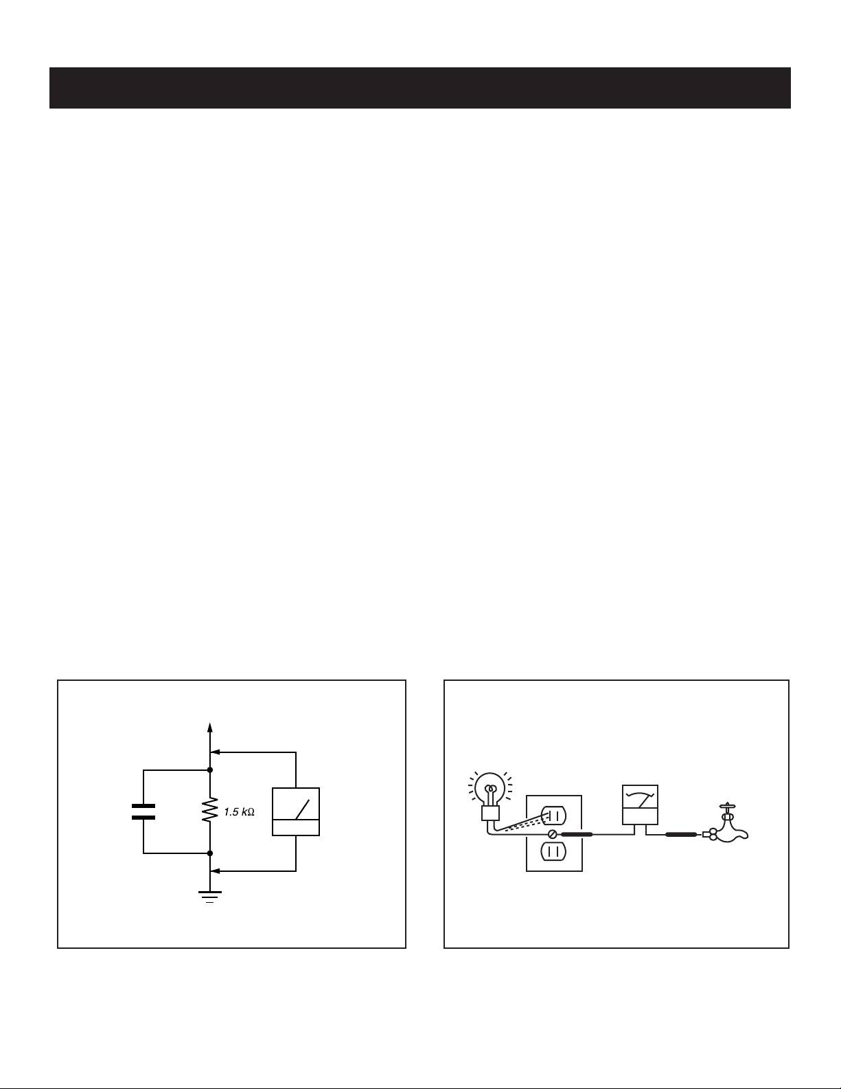
3. Measuring the voltage drop across a resistor by means of a VOM
or battery-operated AC voltmeter. The “limit” indication is 0.75
V, so analog meters must have an accurate low voltage scale.
The Simpson’s 250 and Sanwa SH-63TRD are examples of
passive VOMs that are suitable. Nearly all battery-operated digital
multimeters that have a 2 VAC range are suitable (see Figure A).
How to Find a Good Earth Ground
A cold-water pipe is a guaranteed earth ground; the cover-plate
retaining screw on most AC outlet boxes is also at earth ground. If the
retaining screw is to be used as your earth ground, verify that it is at
ground by measuring the resistance between it and a cold-water pipe
with an ohmmeter. The reading should be zero ohms.
If a cold-water pipe is not accessible, connect a 60- to 100-watt
trouble- light (not a neon lamp) between the hot side of the receptacle
and the retaining screw. Try both slots, if necessary, to locate the hot
side on the line; the lamp should light at normal brilliance if the screw
is at ground potential (see Figure B).
To Exposed Metal
Parts on Set
0.15 μF
Figure A. Using an AC voltmeter to check AC leakage. Figure B. Checking for earth ground.
KDF-46E3000/50E3000
Earth Ground
AC
Voltmeter
(0.75V)
Trouble Light
AC Outlet Box
Ohmmeter
Cold-water Pipe
7
Page 8

KDF-46E3000/50E3000
SELF-DIAGNOSTIC FUNCTION
The units in this manual contain a self-diagnostic function. If an error occurs, the POWER/STANDBY will automatically begin to fl ash. The number of
times the LED fl ashes translates to a probable source of the problem. A defi nition of the POWER/STANDBY fl ash indicators is listed in the instruction
manual for the user’s knowledge and reference. If an error symptom is diffi cult to reproduced use the Remote Commander to display the record that is
stored at the internal NVM to specify the cause of the failure.
Diagnostic Test Indicators
When an error occurs, the POWER/STANDBY will fl ash a set number of times to indicate the possible cause of the problem. If there is more than
one error, the POWER/STANDBY will identify the fi rst of the problem areas. If the errors occur simultaneously, the one that corresponds to the fewest
fl ashes is identifi ed fi rst.
Results for all of the following diagnostic items are displayed on screen. (No error has occurred if the screen displays a “0”.)
Self Diagnosis
Supported model
Number of times
LED indicator
flashes Diagnosis Item Probable Cause
Lamp not seated properly
1 Lamp Error
(Note: The lamp LED will flash red when
this error occurs, not the Power LED)
2 OVP 10.5V is high on B Board
3 LowB Error 10.5V is low on B Board
4 Not Used in this model
5 HV Detect Ballast is not working
6 Lamp Cover/ Lamp Position The Lamp cover is not closed securely.
7 Temp Error High Temperature or sensor connection
8 Audio Error DC error on U Board
9 Fan Error Fan is not working properly
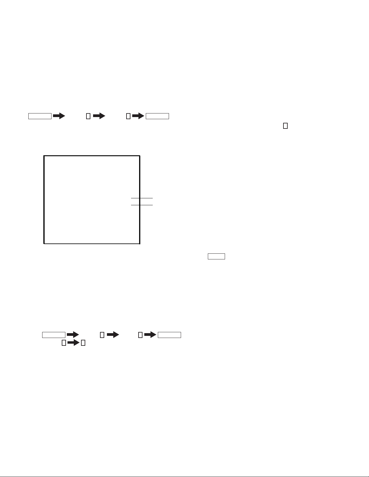
DISPLAY OF POWER/STANDBY OR LAMP LED FLASH COUNT
Screen
TIMER LAMP POWER
Flashes red for Lamp error
TIMER LAMP POWER
Flashes red for all except Lamp error
- 4 Flash is not used for self-diagnosis
-Example
Diagnosis
LowB Error
Number of times LED Flashes
LED OFF
3.0sec
3 times
Lamp Cover 6 times
KDF-46E3000/50E3000
LED ON : 0.3sec
LED OFF : 0.3sec
LED OFF
3.0sec
8
Page 9
KDF-46E3000/50E3000
RELEASING THE POWER/STANDBY LED FLASH
Unplug the power cord from the outlet to temporarily stop the POWER/STANDBY lamp from fl ashing.
Self-Diagnostic Screen Display
For failures that are diffi cult to reproduce, or accompany occasional power off and/or picture mute, the Self-Diagnostic screen display is useful to
specify the cause.
VIEWING THE SELF-DIAGNOSTIC SCREEN
1. TV must be in standby mode. (Power off).
2. Press the following buttons on the Remote Commander within a second of each other:
DISPLAY
NOTE: This differs from the method of accessing service mode which is Volume
Sample Self-Diagnostic Screen Display
Channel
1 : LAMP_ERR 0
2 : OVP 0
3 : LowB-ERROR 0
5:
6:
7 : TEMP-ERROR
8 : AUDIO-ERROR 0
9 : FAN-ERROR 0
5
Volume -
SELF CHECK
HV DETECT
LAMP_COVER 1
0
0
POWER
+
"1" is displayed when an error is detected one or more times
"0" is displayed when no error has been detected
Name: KDF-37H1000
Serial: XXXXXXXXXX
NOTE: To refresh the Self Check menu when all the items are not displayed, press
3. Proceed to Viewing the Self-Diagnostic Errors.
JUMP
on the Remote Commander.
CLEARING THE SELF-DIAGNOSTIC SCREEN
The self-diagnostic results displayed on the screen are not cleared automatically, therefore you should always check the self-diagnostic screen during
repairs. When you have completed the repairs, clear the self-diagnostic screen to reset the results to “0”.
Note: The self-diagnostic function will not be able to detect any subsequent faults after completion of the repairs unless the Self-Diagnostic
result display is cleared to reset the results to “0”.
1. If the Self-Diagnostic screen is already displayed, proceed to step 3. If not, Power off (Set to Standby mode).
2. Press
3. Press Channel 8
The status resets to 0.
4. To exit the Self-Diagnostic screen, turn the power off.
DISPLAY
Channel
0
5
Volume -
POWER
KDF-46E3000/50E3000
9
Page 10
1-1. OVERVIEW
TOOLS NEEDED
Long Phillips Screwdriver
Needle Nose Pliers
Small Flathead Screwdriver or Jewelers Screwdriver
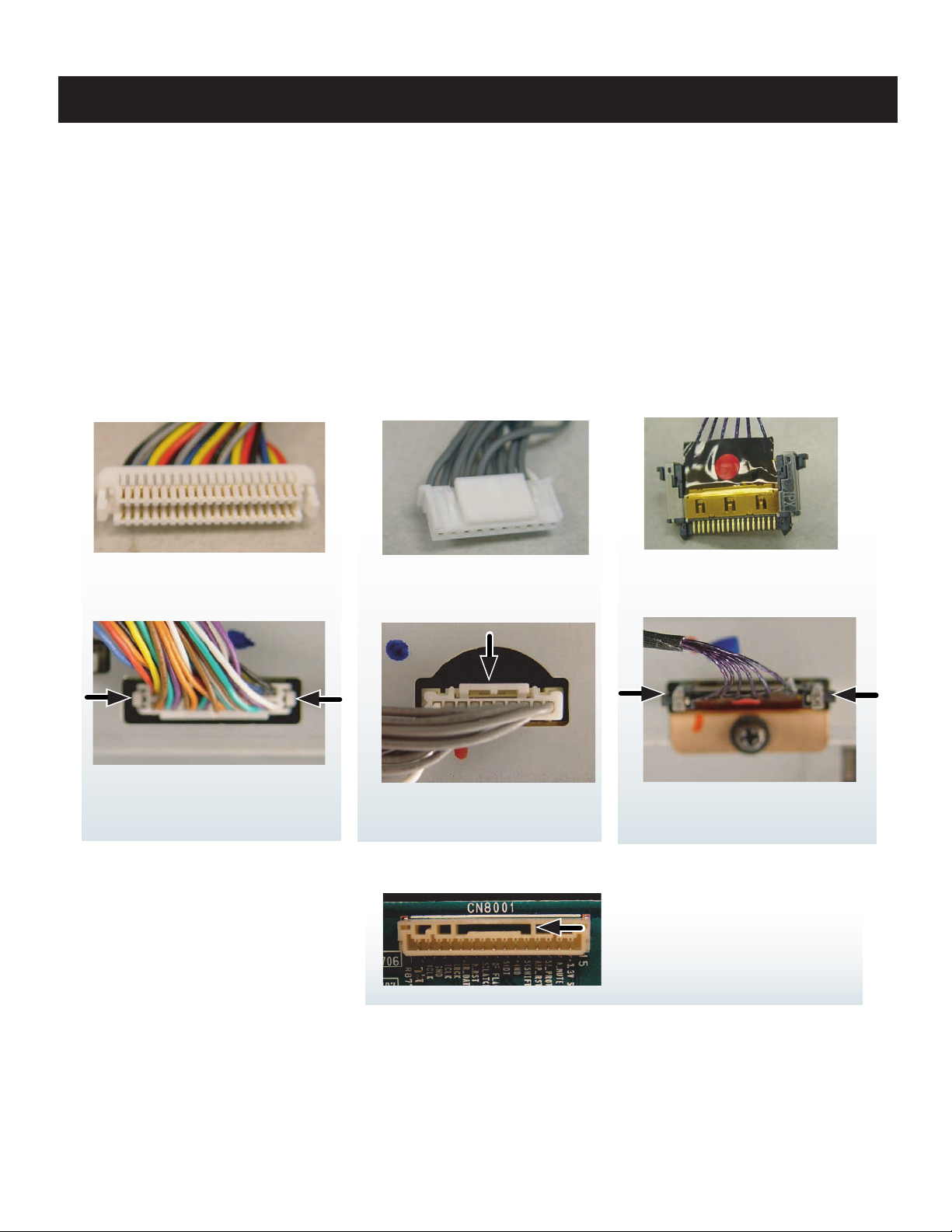
The connectors in this chassis have been redesigned to ensure they are securely fasten to the boards. Please review the illustrations below.
Use caution not to rock the Type 2 or Type 3 connectors when removing or reinstalling to avoid breaking the solder leads off the
Printed Circuit Boards.
KDF-46E3000/50E3000
SECTION 1: DISASSEMBLY
TYPE 1
LIFT ONE SIDE AT A TIME
BY PUSHING TAB IN WITH
SMALL SCREWDRIVER
TYPE 2
SQUEEZE DOWN ON
TAB TO RELEASE
TYPE 3
SQUEEZE LOCKING TAB
TOWARDS CONNECTO R
BEFORE PULLING FREE
CAUTION! IF THE TYPE 2 FEMALE
CONNECTOR HAS A SLOT (AS SHOWN)
MAKE SURE THE LOCK TAB SEATS INSIDE
THIS SLOT.
KDF-46E3000/50E3000
10
Page 11

1-2. LAMP REMOVAL
For detailed instructions, refer to “Replacing the Lamp” in the Appendix section of this manual
1
Remove the Lamp Door and the Lamp Cover.
2
Disconnect the Lamp Block Assembly by pulling
it out of the Power Supply.
KDF-46E3000/50E3000
Lamp Door
Lamp Block Assembly
XL-2500
2
Lamp Cover
1
KDF-46E3000/50E3000
11
Page 12

KDF-46E3000/50E3000
1-3. POWER SUPPLY (BALLAST UNIT) REMOVAL
1
Remove 1 screw (+BVTP2 4x16) from the Power Supply (Ballast Unit Lead Cover)
2
Slide out the Ballast Bracket.
3
Release the connector wire from the Bracket
4
Rotate the Bracket.
5
Disconnect 2 connectors
6
Remove 1 screw (+BVTP 3x12 TYPE2 IT-3) from the Power Supply (Ballast Unit)
Ballast Bracket (E)
Ballast Lead Cover
3
1
Power Supply
(Ballast Unit)
2
4
5
6
KDF-46E3000/50E3000
12
Page 13
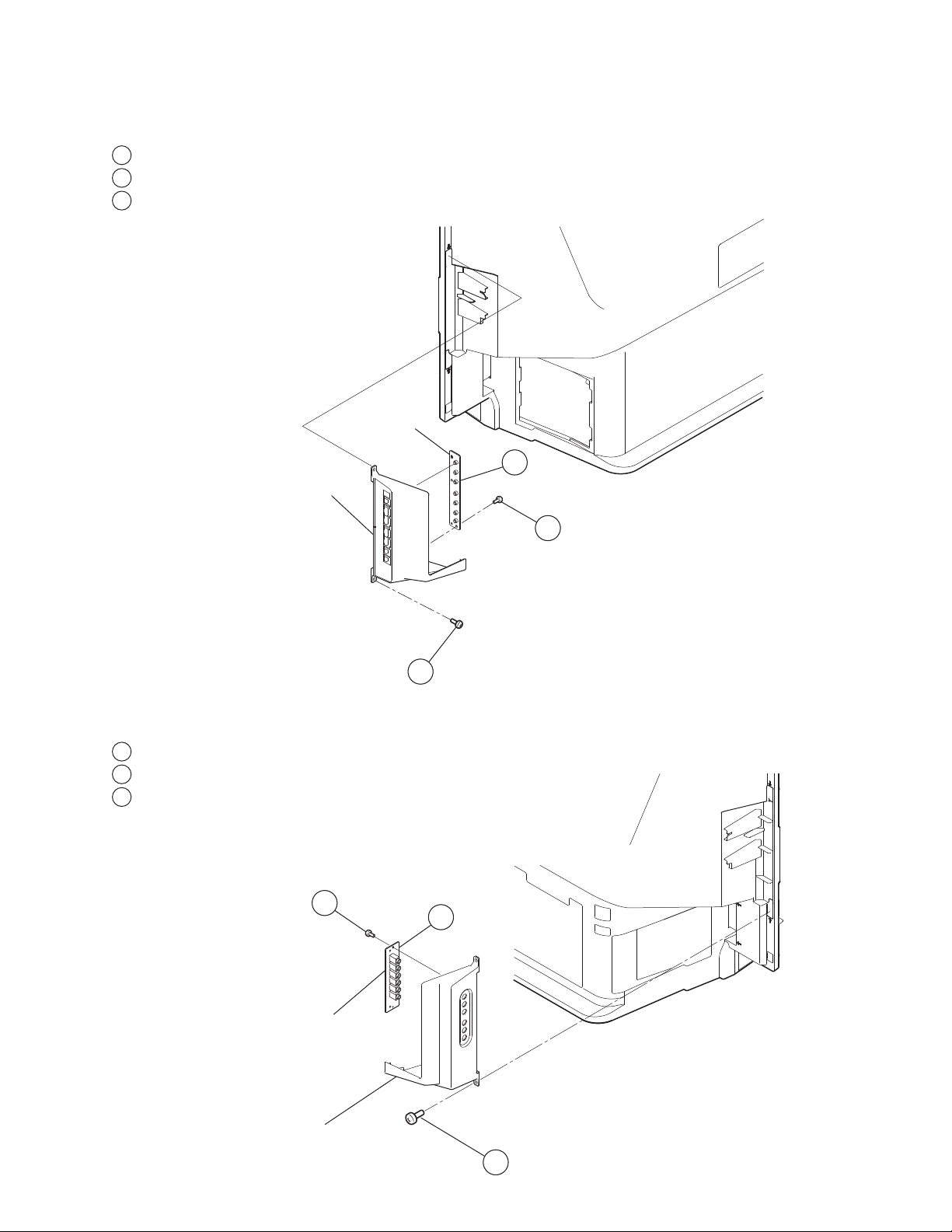
1-4. HAE BOARD REMOVAL
1
Remove 2 screws for 46” model, 3 screws for 50” model, +BVTP2 4x16
2
Disconnect a connector from HAE board
3
Remove 2 screws for HAE board removal, +BVTP 3x12 TYPE2
Side Control Bracket
KDF-46E3000/50E3000
HAE Board
2
1-5. HCE BOARD REMOVAL
1
Remove 2 screws for 46” model, 3 screws for 50” model, +BVTP2 4x16
2
Disconnect a connector from HCE board
3
Remove 2 screws for HCE board removal, +BVTP 3x12 TYPE2
3
1
3
2
Side Terminal Bracket
KDF-46E3000/50E3000
HCE Board
1
13
Page 14

1-6. ORNAMENTAL COVER, SCREEN FRAME, AND LIGHT GUIDE REMOVAL
☛
All of the components of this model can be reached by removing the Screen Frame Assembly from the Rear Cover.
Remove the Side Control Bracket and the Side Terminal Bracket before proceeding. (See 1-4. HAE Board Removal and
1-5. HCE Board Removal.
Caution:
When removing the Rear Cover or the Screen Frame
to remove any dust particles.
1
Remove 20 screws from the Rear Cabinet to release the Screen Frame, +BVTP2 4x16
2
Slide Ornamental Cover to right and pop off from Screen Frame.
3
Remove 3 screws from Screen Frame, +BVTP2 4x16
A
The Light Guide is not included with the Ornamental Cover. When replacing the Ornamental Cover remove 1 screw from
Light Guide, +BVTP 3x12 TYPE2 IT-.
Assembly
, be sure to clean the mirror and Diffusion Plate(s)
KDF-46E3000/50E3000
Rear Cabinet
Screen Frame
3
2
A
Light Guide
1
Ornamental Cover
1
Screen Frame
KDF-46E3000/50E3000
Rear Cabinet
14
Page 15

1-7. DIFFUSION PLATES AND SCREEN FRAME REMOVAL
Caution:
When replacing the Diffusion Plates be sure to remove any dust particles.
1
Remove 5 screws(Top Holder), 6 screws(Bottom Holder) and 3 screws from each side holders, total 17 screws, +BVTP2 4x16
Screen Frame
KDF-46E3000/50E3000
1
Diffusion Plates
1-7-1. DIFFUSION PLATES (SCREENS) TAPE METHOD
Note:
The following diaglam illustrate the taping method when replacing the diffusion Plates.
For Part Numbers refer to the Explode view section of this manual.
Black Acetate Tape
Diffusion Plate
(Lenticular - Front side)
Screen Holder
Diffusion Plate
(Frensnel - Rear side)
KDF-46E3000/50E3000
15
Page 16

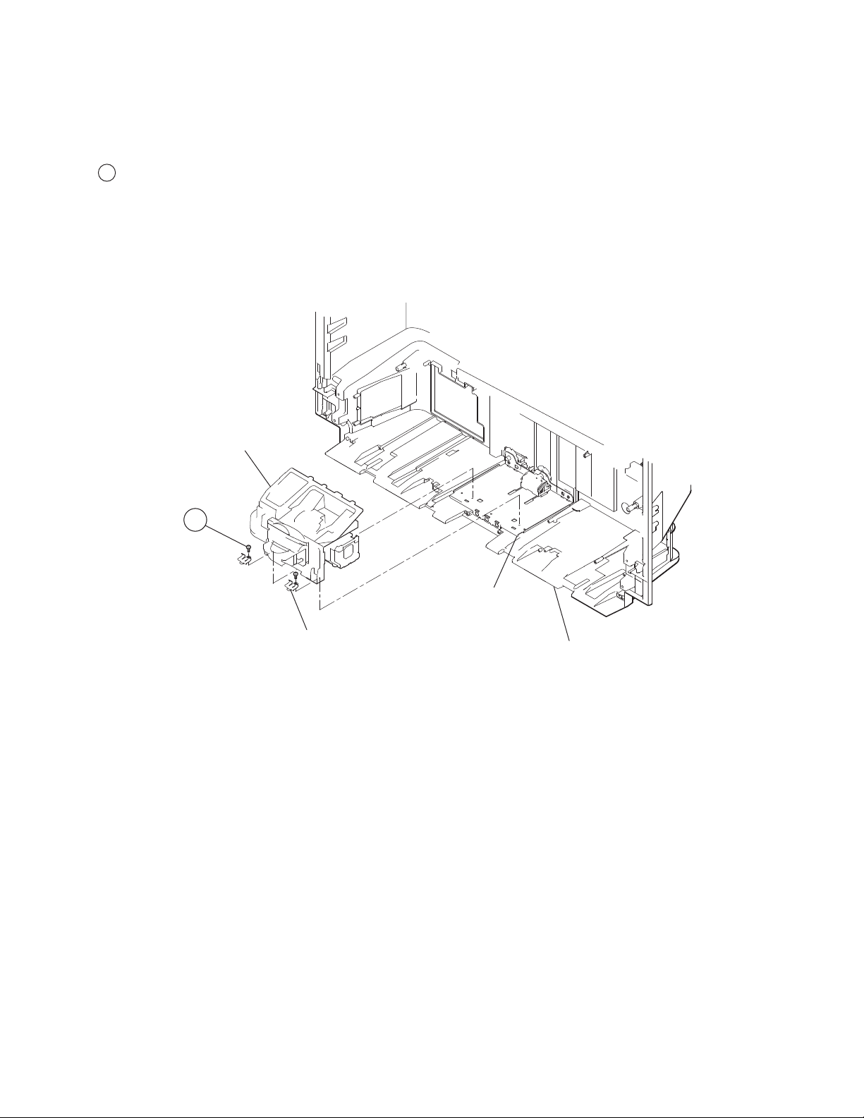
1-8. SEPARATOR, SPEAKER, AND HBE BOARD REMOVAL
1
Remove 9 screws from Separator, +BVTP2 4x16
2
Release connector wires from hook
3
Disconnect joint connectors from HB board
4
Disconnect joint connectors from Speakers
5
Lift tabs and slide out Separator unit.
6
Remove 4 screws from speakers, +BWTP2 4x16
7
Remove 2 screws for HB board removal, +BVTP 3x12 TYPE2 IT-3
KDF-46E3000/50E3000
Rear Cabinet
1
3
4
Separator
2
7
HBE Board
5
5
Speaker
6
KDF-46E3000/50E3000
16
Page 17

1-9. LAMP DUCT REMOVAL
1
Remove 3 screws, +BVTP 3x10 TYPE2 IT-3, connecting the Lamp Duct to the Rear Cover (from the bottom of the Lamp Duct)
2
Disconnect 4 connector joints (not shown)
3
Remove Duct unit from rear cabinet.
4
Slide out Fuse unit from Lamp Duct, locating it inside of the duct.
5
Remove one screw, +BVTP 3x12 TYPE2 IT-3
6
Remove fan from Lamp Duct and take Fan cushions off from fan
7
Remove one screw, +BVTP 3x12 TYPE2 IT-3
Note: To remove each duct, lift tabs gently and release from hooks.
KDF-46E3000/50E3000
4
Lamp Duct (EA)
2
1
Fuse Holder
SE Board
Fuse Sheet
4
Fuse Plate
2P Connector
(Thermal Fuse)
5
6
Fan Cushion
Fan
7
TE Board
3
Rear Cabinet
KDF-46E3000/50E3000
Lamp Duct (EB)
Lamp Duct (EC)
17
Page 18
1-10. OPTICAL UNIT BLOCK REMOVAL
Caution:
When replacing the Optics Unit Block Assembly be sure to remove any dust particles.
1
Remove 2 screws, +PSW M4x12
Note: The connectors are not included with the optical block assembly.
Optical Unit Block
KDF-46E3000/50E3000
1
Optical Unit
Bracket
Main Plate Holder
Main Plate
KDF-46E3000/50E3000
18
Page 19

1-11. CHASSIS REMOVAL
Caution: When replacing any part of the chassis be sure to remove any dust particles and clean the mirror.
1
Disconnect 9 connectors from G board
2
Disconnect a lead wire connector from B board
3
Disconnect 2 connectors from B board
4
Remove 1 screw, +BVTP 3x12 TYPE2 IT-3, from Fan Bracket
5
Remove 2 screws, +BVTP2 4x16
6
Remove one screw, +BVTP 3x12 TYPE2 IT-3
7
Remove 3 screws, +PSW M3X8
8
Remove 6 screws, +BVTP 3x12 TYPE2 IT-3
9
Disconnect 4 connectors from U board
10
Remove 2 screws, SPECIAL (+PW 4X30)
11
Remove 2 screws, +PSW M3X8
12
Remove 2 screws, +BVTP 3x12 TYPE2 IT-3
13
Remove 1 nut from tuner
1
KDF-46E3000/50E3000
G Board
8
G Bracket
7
2
6
B-Shield
10
9
B Board
11
12
13
Terminal
Bracket
U Board
4
3
5
KDF-46E3000/50E3000
Rear Cabinet
Main Base
19
Page 20

1-12. MIRROR REPLACEMENT
CAUTION
1
Replace mirror by laying fl at and face-up position.
2
Holder screws should be tighten from center to outer screw positions.
KDF-46E3000/50E3000
KDF-46E3000/50E3000
20
Page 21
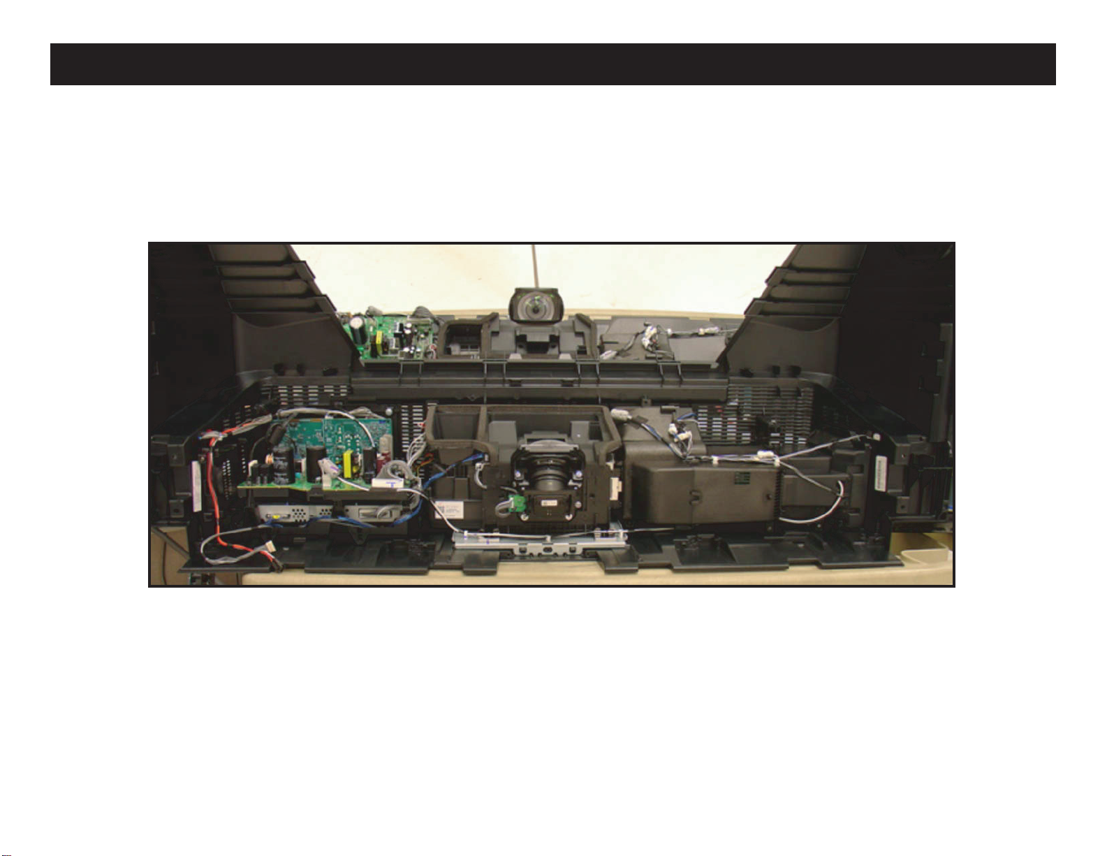
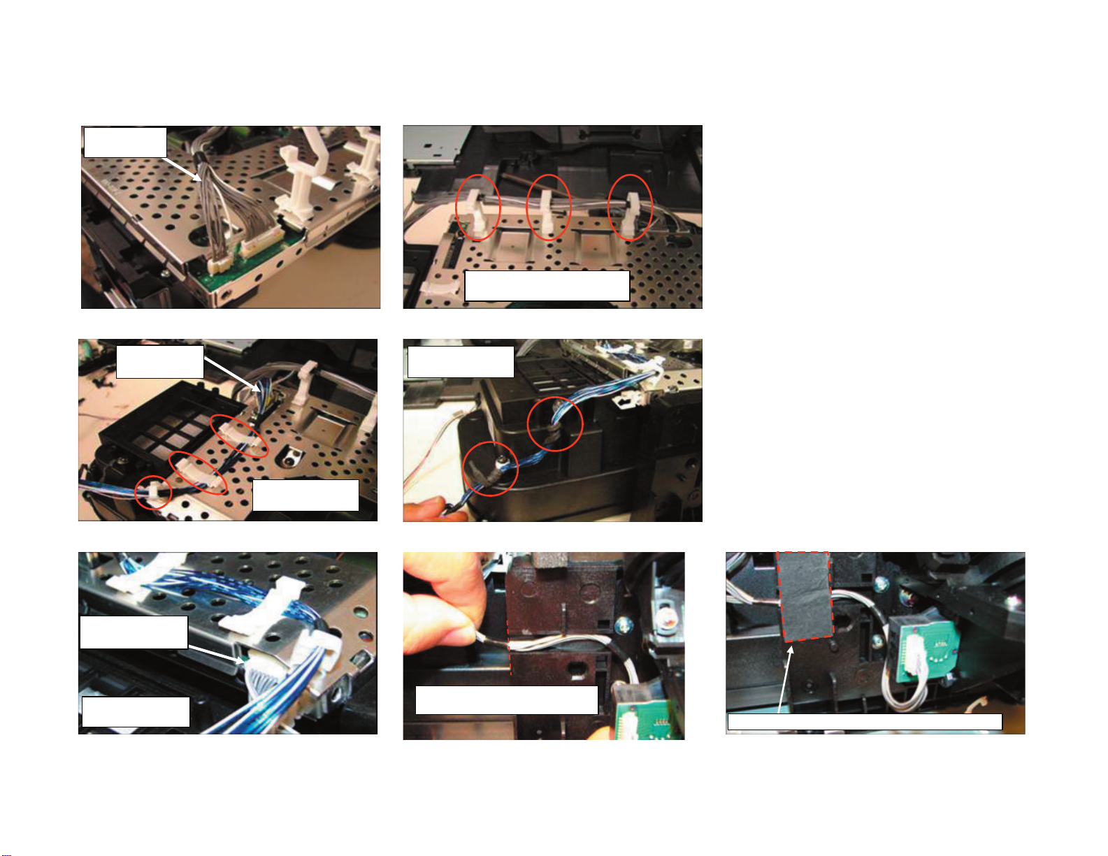
WIRE DRESSING
COMPLETE INTERNAL WIRE DRESSING
KDF-46E3000/50E3000
KDF-46E3000/50E3000
21
Page 22

r
r
A
OVERALL ASSEMBLY
KDF-46E3000/50E3000
fter installing Optical Block route
HARNESS ASSY into clips behind TOP
BRACKET, OPT (E)
Install 8P connector
from [CE] to [BE]
Install 3P Fan Connector
from Optical Block to
HARNESS ASSY
Install 15P connecto
Install 15P connecto
from [CE] to [G]
from [CE] to [G]
Dress 15P Connector
Dress 15P Connector
to wire pin on [G]
to wire pin on [G]
Dress 3P Fan Connector to
clips on TOP BRACKET,
OPT(E) as shown
Install 20P and 9P connector
from Duct Block Assy to [G]
Dress LVDS connector to
on Main Brkt
Install LVDS connector
from [CE] to [BE]
KDF-46E3000/50E3000
clips
22
Page 23
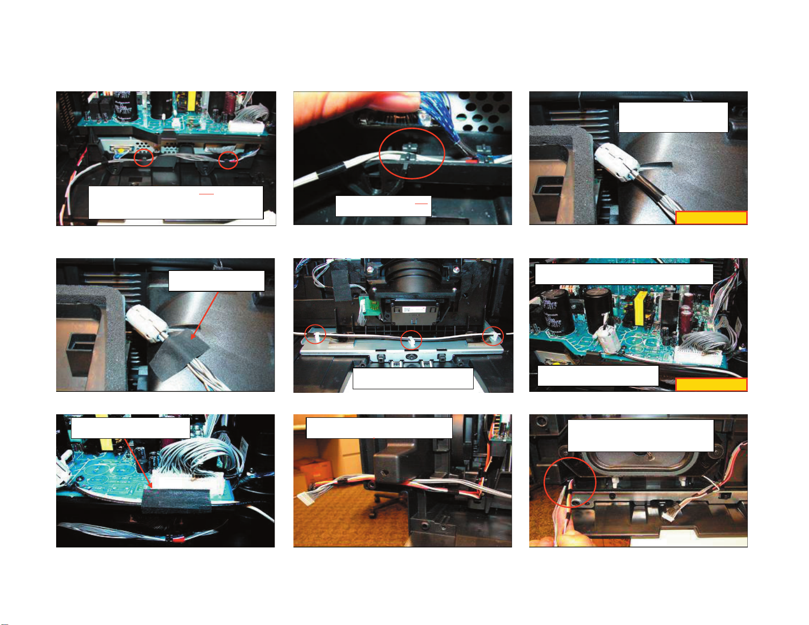
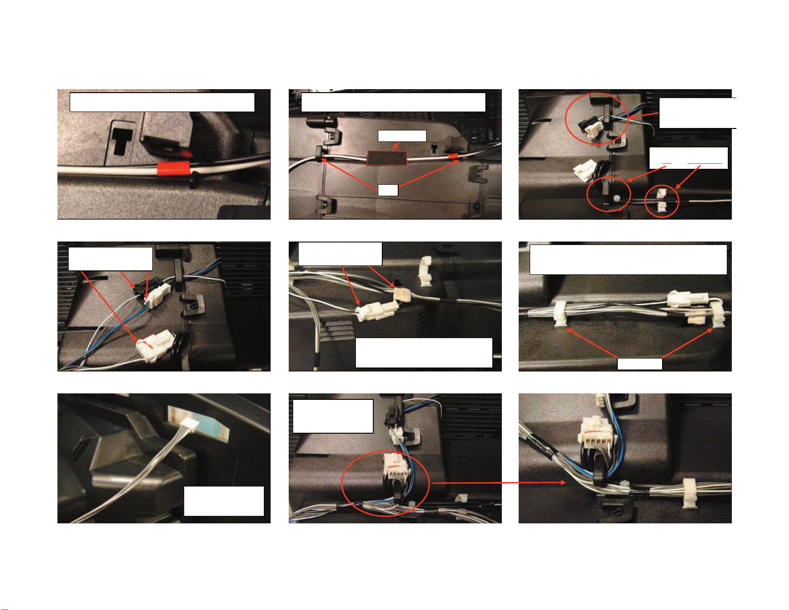
OVERALL ASSEMBLY (CONTINUED)
Dress 8P connector from [BE] to clips on Main Brkt.
RED Tape should line up with clips. This connector
should be on top of LVDS Connector
Dress 8P connector to clip
under LVDS connector
KDF-46E3000/50E3000
Install Ferrite Clamp
(146908911) to HARNESS
ASSY as shown.
CRITICAL FOR EMI
Secure HARNESS ASSY
with 20 X 40 HIMELON tape
Secure Ballast Power with 20 X 40
HIMELON tape as shown
Route Ballast Power as shown and
install to wire holders
Route 4P Speaker and 9P HAE connector
as shown before installing Seperator Blk
Install Ballast Power to [G], install Ferrite Clamp
(146908911) and dress to wire pin on [G] as shown.
Ferrite Clamp must be vertical and
as close to Connector as possible
After installing Separator Blk Assy ensure
4P and 9P Connetor are not pinched
between Rear cover and Separator
CRITICAL FOR EMI
KDF-46E3000/50E3000
23
Page 24
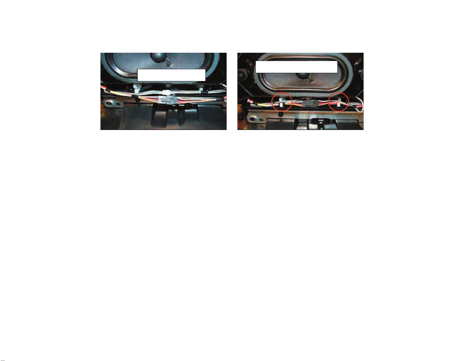
SPEAKER ASSEMBLY
Connect 4P Speaker and 9P HAE
connector as shown .
KDF-46E3000/50E3000
Dress 4P Speaker and 9P HAE connector
to wire holders on Separator Blk Assy
KDF-46E3000/50E3000
24
Page 25
OPTICAL BLOCK ASSEMBLY
191003656
Harness Assy
KDF-46E3000/50E3000
Dress 191003656 to (3) Wire
Holders on CE Block
183411811 LVDS
Connector Assy
191003666
CONN ASSY, 8P 200
8P connector should be
below LVDS
Dress to (2) wire
holders as shown
Dress to (3) Wire
Holders on CE Block
Place wire into channel in Optical Blk.
Line up edge with tape on 8P Connector
Secure 8P Connector with 20 X 40 Himelon Tape 265206401
KDF-46E3000/50E3000
25
Page 26

A
DUCT BLOCK ASSEMBLY
KDF-46E3000/50E3000
191002827
CONNECTOR ASSY 2P
fter installing 7P
Conn assy Secure to
Ballast Bracket with
20 X 40 Himelon
Tape 265206401 as
Shown. This is to
avoid it from hitting
Capacitor on ballast
5P Connector should be
under 2P Connector
191003664
CONN ASSY, 5P SMR 60
191003658
CONN ASSY, 7P 455
[T] Board
191003517
CONN ASSY 3P, SMR
191003659
CONN ASSY, 3P VH1120
Route Duct Blk Fan
toward [T] as shown
Use Caution when installing Duct block that 5P
and 2P Connectors are not pinched
191003658
CONN ASSY, 7P 455
Connector should be
routed outside of post
Secure Both Connectors to hooks on Ballast bracket and
ensure Ferrite core is placed in rib as shown
Rib
Hooks
KDF-46E3000/50E3000
After Installing Ballast Bracket route wires through
openings in Duct Block as shown.
26
Page 27
DUCT BLOCK ASSEMBLY (CONTINUED)
KDF-46E3000/50E3000
Install Ballast Power in Clip on bottom of Duct Block.
Wire should be routed with RED tape in this position
191003657
HARNESS ASSY
Install Ballast Power to Clip and secure with Himelon
Tape 20 X 40. Tape should be centered between clips
Himelon Tape
Clips
191003657
HARNESS ASSY
Connect 9P Ballast Control Connector and
2P Thermal Fuse Connector from
HARNESS ASSY 191003657
Route 3P Fan and 3P
[S] connector to clip on
top of Duct Blk.
Route 2P Thermal fuse
and wire holder.
to clip
Secure Harness Assy, 2P Thermal fuse,4P [HAE], and 9P
Ballast control connector to wire holders as shown.
NOTE: Ensure 9P Connector is routed as shown
Wire Holders
KDF-46E3000/50E3000
Route HARNESS ASSY
191003657 to Clip on
Duct Block.
Route 4P [HAE]
Connector through
Opening in Rear Cover
27
Page 28
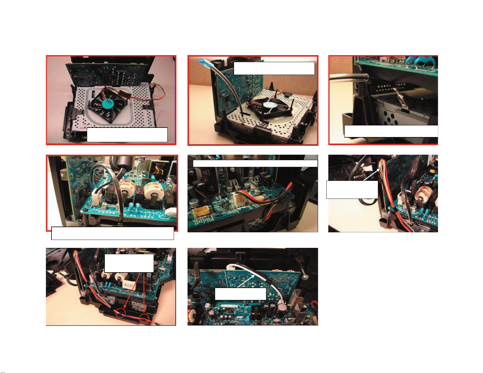
A
r
b
CHASSIS ASSEMBLY
KDF-46E3000/50E3000
fter installing Fan Secure wire with 20 X
40 Himelon Tape as shown.
Lighting ground should be behind AC cord. UL Tube should be
located on [G] board side of connection as shown below
WIRE ASSY, FASTON TERMINAL
191003511
191003507
Dress 3P Chassis Fan Connector to WIRE PIN on [G] as shown
Before Installing [G] Board it may be necessa
bend tab slightly in order to properly install [G]
191003667
CONN ASSY, 4P
SPEAKER SMR
Dress 4P Speaker
Connector to (2) Clips
on Main Bracket
191003508
CONN ASSY, 3P VH 130
KDF-46E3000/50E3000
28
Page 29

CHASSIS ASSEMBLY (CONTINUED)
KDF-46E3000/50E3000
191003507
CONN ASSY, 40P
Dress 40P Connector to WIRE PIN on [G]
191003660
CONN ASSY, 9P
ZMR 500
KDF-46E3000/50E3000
29
Page 30

HCE BLOCK ASSEMBLY
KDF-46E3000/50E3000
HARNESS ASSY MUST BE INSTALLED BEFORE
PUTTING INTO HC BRACKET
191003665
HARNESS ASSY
Route HARNESS ASSY THROUGH
OPENING IN THE REAR COVER
Dress to wire holder installed on HCE Board.
Ensure connector is routed so that it does not go
above red line shown above.
Install on [U] board as shown. Connector
should be above 3P Connector
Dress to wire holder
on FAN BRACKET
Dress to Wire Holder on Terminal Bracket.
46" Models must be looped to take up excess slack
50" Models DO NOT need to be looped
KDF-46E3000/50E3000
Correct Routing
of HC wire
30
Page 31

r
SEPARATOR BLOCK ASSEMBLY
KDF-46E3000/50E3000
Dress Speaker Wire to clips on Separator before
installing. Black tape should be inside of clips.
Dress Speaker Wire and 9P [HBE] connector to wire
holders on the FRONT STAY
DO NOT install to wire holder
this should be done later.
Route 9P and Speaker
Wire as shown.
191003661
CONN ASSY, 9P ZHR 860
Route 9P and Speake
Wire as shown.
9P [HBE] should be
under speaker wire
KDF-46E3000/50E3000
31
Page 32

SECTION 2: CIRCUIT ADJUSTMENTS
KDF-46E3000/50E3000
2-1. USING THE REMOTE COMMANDER
FOR ELECTRICAL ADJUSTMENTS
To adjust various set features, use the Remote Commander to put the
set into service mode to display the service menus and categories.
Equipment Needed:
Pattern Generator (with component outputs)
Oscilloscope
Digital multimeter
2-2. ACCESSING SERVICE ADJUSTMENT
MODE
1. TV must be in standby mode. (Power off).
2. Press the following buttons on the Remote Commander within a
second of each other:
DISPLAY
Channel 5 Volume +
DISPLAY
POWER
5
JUMP
Displays
Service Menus
POWER
.
2-3. VIEWING THE SERVICE MENUS
Use the Remote Commander to view the BE and Digital service menus
options.
1. To display the Service Menu that contains the Category you want to
adjust, press
(For a complete list of the service Categories refer to Service Menus)
SOFTWARE VERSION
VIDEO1 WIDE ZOOM
Press JUMP
PANEL
DIFF 1 60HZ
Press JUMP
0
0
JUMP
TVM:
ATSC:
BE:
NVM:
SWDL
F A:
CBA:
on the Remote Commander.
SERVICE
480I
P1. 000U. - BOOT: 0.005
HO7-01.01 0035
2.710 BOOT:A.103
AO-1.001:OK AC-1.000:OK
0.000
00000000 00000000
00000000 00000000
SERVICE
OPMODE
ONO
VOLUME (+)
RM-YD016
The fi rst service menu (TV) displays.
Onscreen cursor
and select button
WEM VERSION
Main
WM2. 710U00GA
Diff
WM2. 710U00GA
DL 0. 00 Gra 0216
SelfCheck 00 00 00 00
DEM VERSION
PMO. 000 PBO. 000
NVM: PDO. 000
Press JUMP
QM 0 0 SERVICE
INFO DTV
Press JUMP
Boot
Boot
Sample Service Menu
WM1. 103W00AA
WC2. 712U00GAa
KDF-46E3000/50E3000
32
Page 33

KDF-46E3000/50E3000
2-4. USING THE REMOTE COMMANDER TO
1. Access Service Adjustment Mode and select the Service Menu that
VIEW SERVICE DATA
Use the buttons on the Remote Commander to access the service menu
items and adjust the data values.
Adjustment
Item
Data Value
1 SN1 1
SN: 00000000
Service
Menu
Increase
3
Data Value
6
Decrease
Data Value
Display
5
Previous
Category
Read data
9
JUMP
Displays
Service Menus
Category
Display
Next Item
Display
Next Category
2
Display
Previous Item
Saves data
Item
Number
MODEL SERVICE
VIDEO1 WIDE ZOON 480I
NAME: KDF-46E3000
1
4
0
2. To change the Category, press 2 or 5 on the Remote Commander.
Note: Pressing 2 or 5 only changes the categories within the
3. To change the Adjustment Item, press 1 or 4 on the Remote
2-4-1. CHANGING SERVICE DATA
The service data values have been selected to provide the best
possible viewing performance. Although some of the data values
are adjustable, the adjustments are very sensative and changing
them may reduce the picture quality of the set. The following
instructions are provided for informational purposes only.
4. To change the Data Value, press 3 or 6 on the Remote
5. To save the changes, press
2-4-2. EXITING SERVICE MODE
After completing the changes, exit service mode.
6. To exit service mode, turn the power off by pressing
Wait 2 minutes before restarting the set to allow the fans to
2-5. UPDATING THE MODEL INFORMATION
contains the Category with the Adjustment Item you want to change.
Service Menu displayed. To change a Category on one of the other
Service Menus, press the
Menu is displayed.
Commander.
Commander.
completely shut down or the Service Menu will appear on the screen.
JUMP
button until the correct Service
MUTING
then 0 to write into memory.
POWER
.
WHEN REPLACING THE BE BOARD
MUTING
Writes data
into memory
RM-YD016
Use following instructions to update the model specifi c information
after replacing the BE Board.
1. TV must be in standby mode. (Power off).
2. Press the following buttons on the Remote Commander within a
second of each other:
DISPLAY
3. Press 2 on the Remote Commander until the MODEL category
displays.
4. The fi rst adjustment item to display is SZID. The initial data value of
the SZID adjustment item is set to 0 and displays the Model name as
KDF-37H1000. To change the Model name, press 3 on the Remote
Commander until the correct Model name displays. 3 displays KDF-
46E3000 and 4 displays KDF-50E3000.
5. Press 1 on the Remote Commander until the SN8 adjustment item
displays.
NOTE: The SN1 adjustment item displays fi rst, however, SN8 allows
you to change the fi rst digit of the serial number.
6. The initial data value of the SN8 adjustment is set to 0 and displays
the serial number as 00000000. To change the fi rst digit of the serial
number to the correct number, press 3 on the Remote Commander
until the correct fi rst digit displays.
7. Press 4 on the Remote Commander to display the SN7 adjustment
item.
Channel 5 Volume +
POWER
.
KDF-46E3000/50E3000
33
Page 34

KDF-46E3000/50E3000
t
s
s
/
8. Change the data value of the serial number to the correct serial
number, by pressing 3 on the Remote Commander until SN7
adjustment displays. (SN7 is the second digit of the serial number
range.)
9. Repeat steps 7 and 8 for SN6 through SN1 until the correct serial
number displays.
10. To save the changes, press
After completing the changes, exit service mode.
11. To exit service mode, turn the power off by pressing
MUTING
then 0 to write into memory.
POWER
.
2-5-1. VERIFYING MODEL INFORMATION
Verify the changes to the model information by viewing the
information in the Product Support category of the user Settings
menu options.
1. Turn the TV on by pressing
2. Press
The user menu icons display.
HOME
Menu items.
on the Remote Commander to display the User
Settings
POWER
on the Remote Commander.
Product Support
Clock/Timers
2-6. ADJUSTING THE HORIZONTAL AND
VERTICAL SETTINGS
1. Turn the TV on by pressing
2. Press
The user menu icons display.
3. Press the
4. Press the
HOME
Menu items.
Settings option, and then press the
Screen Settings category, and then press the
on the Remote Commander to display the User
buttons on the Remote Commander to select the
B/b
button on the Remote Commander to select the
V/v
POWER
Screen Setting
5. Press the
Screen Position category, and then press the
6. Press the
Vertical or Horizontal position, and then press the
increase or decrease the position.
button on the Remote Commander to select the
V/v
button on the Remote Commander to select the
V/v
on the Remote Commander.
button.
button.
button.
buttons to
B/b
2-7. RESETTING THE LAMP
Use the following to reset the lamp after replacement.
1. Turn the TV on by pressing
2. Press
The user menu icons display.
3. Press the
4. Press the
HOME
Menu items.
Settings option, and then press the
General Settings category, and then press the
on the Remote Commander to display the User
buttons on the Remote Commander to select the
B/b
button on the Remote Commander to select the
V/v
POWER
on the Remote Commander.
button.
button.
Sound
Screen
Video Options
3. Press the
Settings option, and then press the
4. Press the
Product Support category, and then press the
buttons on the Remote Commander to select the
B/b
button.
button on the Remote Commander to select the
V/v
button.
Product Suppor
5. Press the
Contact Sony option, and then press the
6. Verify the changes you made in Service Mode are correct.
buttons on the Remote Commander to select the
B/b
button.
General Setting
5. Press the
Replacement category, and then press the
6. To select Yes, press the
button on the Remote Commander to select the Lamp
V/v
button.
button and then press the button.
B
2-8. VERIFYING SERVICE DATA CHANGES
1. After completing all adjustments turn the set off with the Remote
Commander and WAIT for the fans to turn off before proceeding to
the next step.
Note: It may take up to two minutes for the fans to stop.
Caution: To avoid over heating the lamp, do not unplug the set
until the fans have stopped.
2. Press the following buttons on the Remote Commander within a
second of each other:
DISPLAY
3. To verify the changes repeat steps 1 through 3 of 2-4. Using the
Remote Commander to View Service Data.
4. To exit service mode, turn the power off by pressing
NOTE: After exiting service mode wait 2 minutes before restarting
the set to allow the fans to shut down properly.
Channel 5 Volume +
POWER
POWER
.
.
KDF-46E3000/50E3000
34
Page 35

2-9. RESETTING TO FACTORY DEFAULTS
Use the following instructions to restore the User Controls and
Channel Memory settings to the preset factory conditions.
KDF-46E3000/50E3000
1. While holding down the
POWER button on the Front Panel of the set.
The set restarts and displays the initial setup screen. This may take
several minutes.
on the Remote Commander, press the
KDF-46E3000/50E3000
35
Page 36

3-1. CIRCUIT BOARDS LOCATION
KDF-46E3000/50E3000
SECTION 3: DIAGRAMS
3-2. PRINTED WIRING BOARDS
B-BLOCK
G
U
OPTICAL UNIT BLOCK
(Includes the C Board)
HCE
SE
TE
HBE
HAE
AND SCHEMATIC DIAGRAMS INFORMATION
All capacitors are in μF unless otherwise noted. pF : μμF 50WV or
less are not indicated except for electrolytics and tantalums.
All electrolytics are in 50V unless otherwise specifi ed.
All resistors are in ohms. kΩ=1000Ω, MΩ=1000kΩ
Indication of resistance, which does not have one for rating
electrical power, is as follows: Pitch : 5mm
Rating electrical power :
1
/
W in resistance, 1/
4
W and 1/
10
W in chip resistance.
16
1
/
W
4
: nonfl ammable resistor
: fusible resistor
: internal component
: panel designation and adjustment for repair
: earth ground
: earth-chassis
All variable and adjustable resistors have characteristic curve B,
unless otherwise noted.
Readings are taken with a color-bar signal input.
Readings are taken with a 10MΩ digital multimeter.
Voltages are DC with respect to ground unless otherwise noted.
Voltage variations may be noted due to normal production
tolerances.
All voltages are in V.
S : Measurement impossibility.
: B+line.
: B-line. (Actual measured value may be different).
: signal path. (RF)
Circled numbers are waveform references.
The components identifi ed by shading and ! symbol are critical for safety. Replace
only with part number specifi ed.
The symbol indicates a fast operating fuse and is displayed on the component
side of the board. Replace only with fuse of the same rating as marked.
!
Les composants identifi es per un trame et une marque
securite. Ne les remplacer que par une piece portant le numero specifi e.
Le symbole indique une fusible a action rapide. Doit etre remplace par une
fusible de meme yaleur, comme maque.
NOTE: The components identifi ed by a red outline and a mark contain confi dential
information. Specifi c instructions must be adhered to whenever these components
are repaired and/or replaced.
See Appendix A: Encryption Key Components in the back of this manual.
sont critiques pour la
KDF-46E3000/50E3000
36
Page 37

REFERENCE INFORMATION
(
)
RESISTOR
: RN METAL FILM
: RC SOLID
: FPRD NONFLAMMABLE CARBON
: FUSE NONFLAMMABLE FUSIBLE
: RW NONFLAMMABLE WIREWOUND
: RS NONFLAMMABLE METAL OXIDE
: RB NONFLAMMABLE CEMENT
: ADJUSTMENT RESISTOR
COIL
: LF-8L MICRO INDUCTOR
CAPACITOR
: TA TANTALUM
: PS STYROL
: PP POLYPROPYLENE
: PT MYLAR
: MPS METALIZED POLYESTER
: MPP METALIZED POLYPROPYLENE
: ALB BIPOLAR
: ALT HIGH TEMPERATURE
: ALR HIGH RIPPLE
KDF-46E3000/50E3000
Terminal name of semiconductors in silk screen
printed circuit ( )
Device Printed symbol Terminal name
Transistor
1
Transistor
2
3
Diode
4
Diode
Diode
5
Diode
6
Diode
7
8
Diode
Diode
9
Diode
0
Diode
qa
Diode
qs
Transistor
qd
(FET)
Transistor
qf
(FET)
Transistor
qg
(FET)
Transistor
qh
Transistor
qj
Transistor
qk
Transistor
ql
Transistor
w;
Transistor
wa
Transistor
ws
Transistor
wd
Discrete semiconductot
–
Chip semiconductors that are not actually used are included.
*
Collector
Base
Collector
Base
Cathode
Cathode
Anode
Cathode
Anode
Common
Anode
Common
Anode Cathode
Common
Anode
Common
Anode Anode
Common
Cathode
Common
Cathode
Anode
Anode
Cathode
Drain
Drain
B1 E1C2
B2 C1
E2
B2 E2C1
B1 C2
E1
B2 E2
C1
B1 C2E1
B2 E2
C1
B1 C2E1
E2
B1 E1
(B2)
E1
B1
(B2)
E1
E2
C2
Emitter
Emitter
Anode
(NC)
(NC)
Cathode
Anode
Cathode
Cathode
Cathode
Anode
Anode
Source
Gate
Source
Gate
Source
Drain
Gate
Emitter
Collector
Base
C1(B2)C2
E2
C2C1
B1
C1
Circuit
D
G
D
S
B1
B1
B1
B1
B1
B1
D
G
S
S
D
G
C1
E1
C1
E1
E1
C1
E2
C1
C1
G
S
C2
B2
E2
C2
B2
E2
E2
B2
C2
C2C1(B2)
E2
E2E1(B2)
C2
C2E1(B2)
C2
Ver.1.5
KDF-46E3000/50E3000
37
Page 38

3-3. BLOCK DIAGRAMS
SIGNAL FLOW BLOCK DIAGRAM
KDF-46E3000/50E3000
+$&%3)'.!,&,/7
"US)&
4UNER
$EMOD
.43#"43#
(#
#/-0
6)$%/
36)$%/
$46)&
)3
30$)&
#69#9#B#R
30)
-B
!4I8),,%/.
.!.$
&LASH
-B
3-!6
X
,0&
$$2
-B
.6KB
BIT$$2A2'"
BITSYNC
5!24!4)*)'
##08!
#8$
2'A
&,)0&,/0
4#6#8&4
'"A
BIT
5!2446!4)
$E-58
BIT
$2#-&6
#8$1
$$2
$$2
-B
-BX
)&03
#8$
7%-ICRO
!2-
.6-
KB
$IGITAL6IDEO
!NALOG6IDEO
5!24467%
BIT2'"X
#-/3
&LASH
-B
46-ICRO
3AIPH
"%
,6$3
4X
$IGITAL!UDIO
)#7%
)#46
!NALOG!UDIO
#%
.!#%,
%PSON
,%
)#.!#%,
$%-ICRO
)#$%
.6-
KB
,INE"US
"US
3W
$IGITAL6IDEO
-EMORY
#ONTROL
2,#$$R
ON&&#
',#$$R
ON&&#
",#$$R
ON&&#
.6-
KB
,-!
0ANEL
6)$%/
#/-0
#/-0
!5$)/
&OR$6)
!UDIO/54
/PT!UDIO
5
6IDEO37
!UDIO37$30
#8!2
4!3
#LASS$ !-0
40!$
3$2!-
-B
30%!+%2
,7
30%!+%2
27
)3
3$2!-
-B
($-)%Q
#8"!2
($-)
($-)
9#B#R BIT&ORP
9#B#R BIT2'"BIT
($-)2X
3I)
"US3W
KBX
($-)
-ICRO
%$)$
)#($-)
)#!$30
5!2446*)'
)#46
"53#ONNECTOR
)2)3
&!.
'
6 6
"US,EVEL3HIFT
3
,-!
,!-0
(#
,-!
&!.
KDF-46E3000/50E3000
38
Page 39

CONNECTION DIAGRAM
KDF-46E3000/50E3000
S
P
HBE
CN110
CN6002
CN3008
CN3006
G
CN6904
CN3002
BE
CN6501
CN6906
CN6802
CN6804
CN6009
CN6019
CN3750
CN3700
CN3009
TO LAMP DRIVER
TO FANS
CN160
CN150
CN100
SE
TE
HAE
CN8150
CN8152
CN8151
CN8300
CE
S
P
TO IRIS
KDF-46E3000/50E3000
HCE
CN180
CN181
Included with optical block
CN2503CN2502
CN2504
U
CN2500
CN2501
CN2000
BtoB
Conventional
LVDS
39
Page 40

3-4. SCHEMATICS AND SUPPORTING INFORMATION
BE BOARD SCHEMATIC DIAGRAM (1 OF 12)
KDF-46E3000/50E3000
A
—
B
—
C
—
D
—
E
—
F
—
G
—
H
—
I
—
J
—
K
—
L
—
M
—
N
—
O
—
P
1 | 2 | 3 | 4 | 5 | 6 | 7 | 8 | 9 | 10 | 11 | 12 | 13 | 14 | 15 | 16 | 17 | 18 | 19 | 20 | 21 | 22 | 23 |
TO HBE BOARD
CN110
CN3008
9P
STBY_5V
FAN2/4-VC
R3010
22k
1/16W
RN-CP
0.5%
2
R3009
1/16W
RN-CP
L3000
10uH
47k
0.5%
1
A5V
2
C3002
1608
L3001
10uH
0.1
16V
B
1
R3002
470k
1/16W
CHIP
5%
1
2
12
C3000
C3001
0.1
47
10V
16V
B
1608
1
2
12
C3004
C3003
47
10V
I
VSS
IC3006
XC6203P182PR
1.8V REG.
R3007
47k
1/16W
RN-CP
0.5%
Q3006
2SC3052EF-T1-LEF
S-VBUS
S-UDM
S-UDP
S-UDP
R3019
0
12
CHIP
1005
IC3001
TAR5S33(TE85R)
5
54
3.3V REG.
123
12
STBY1.8V
1
C3006
2
12
0.1
16V
B
1608
O
HDMI-CEC/OUT
FAN-CTRL
FAN-PROT
ADSP-MUTE
LINE-MUTE
LAMP-CTRL
LAMP-COVER
LAMP-PROT
S-UDM
R3020
0
12
CHIP
1005
4
321
12
12
C3007
C3005
0.1
0.01
16V
25V
B
B
1608
1608
47
6.3V
FAN1-VC
FAN3-VC
SP-MUTE
HV-DET
S-VBUS
RT1N141C-TP-1
STBY_3.3V
TIMER_LED
PITMUTE_LED
GND
STBY_3.3V
STBY_3.3V
12
1
C3008
6.3V
2
47
C3011
0.01
1608
2
1
12
L3002
10uH
25V
B
X3000
48MHz
12
C3012
0.01
25V
1608
B
C3009
1608
12
C3014
6.3V
10
L3003
10uH
2
1
RB3006
100
10V0.1
10V0.1C3087
10V0.1
47R3029
R3021
10k
1/16W
CHIP
12
47kR3111
47kR3112
47kR3113
R3115
100
RB3008
100
RB3009
100
0
CHIP
R3108
22
R3012
1/16W
12
C3015
0.1
R3031
47
1/16W
12
12
1/16W
1.5kR3028
1/16W
R3075
10k
1/16W
CHIP
5%
Q3017
RT1N141C-TP-1
12
133
134
135
136
137
138
139
140
141
TP3007
142
143
144
145
146
147
148
149
150
151
152
153
154
155
156
157
158
159
160
161
162
163
164
165
166
167
168
169
170
171
172
173
174
175
176
12
12
1
C3013
22
10V
2
TP3009
C3089
C3088
16V0.1C3010
12
12
R3003
47k
1/16W
3
CHIP
5%
12
0.1
16V
B
MAIN-H
TIMER-LED
PICMUTE-LED
RB3011
100
I_HDMI_HPD1
I_HDMI-PID2
I_HDMI-PID3
O_HDMI_HPC1
I_HDMI_HPD2
0_HDMI_HPC2
I_HDMI_HPD3
O_HDMI_HPC3
O_HDMI_CEC/OUT
O_IRIS_BL
O_FAN1_VC
O_FAN3_VC
O_FAN_CTRL
I_FAN_PROT
O_ADSP_MUTE
O_SP_MUTE
O_LINE_MUTE
O_LAMP_CTRL
I_LAMP_COVER
I_LAMP_PROT
I_LAMP_HV_DET
I_USB_DET
L1.8V
USB_CLK1
GND
USB_CLK0
3.3V
UDM
UDP
O_D_B0
O_D_B1
O_D_B2
O_D_G0
O_D_G1
O_D_G2
O_D_R0
O_D_R1
O_D_R2
L1.8V
O_YM
O_YS
FH
DOT_CLK_O
DOT_CLK_I
I_OSD_V
I_OSD_H
I_MAIN_H
1234567891011121314151617181920212223242526272829303132333435363738394041424344
12
R3039
100
1/16W
CHIP
5%
STBY_3.3V
12
2
Q3009
2
R3054
1/16W
CHIP
STBY_3.3V
10k
12
5%
Q3016
RT1N141C-TP-1
2
12
LAMP_LED
CHIP
CHIP0
0R3071
12
R3073
LAMP-LED
STBY-LED
HDMI-MICRO-RST
I_HDMI-PID1
O_HDMI_RST
HSYNC3
3.3V
R3044
10k
1/16W
CHIP
5%
RT1N141C-TP-1
R3057
10k
1/16W
CHIP
5%
RT1N141C-TP-1
STBY_LED
CHIP
0
12
R3022
POWER-LED
DL-MODE
O_DL_MODE
GND
Q3102
2
Q3101
2
SIRCS
GND
POWER_LED
123456789
CHIP
CHIP
0
0
12
12
R3023
R3074
WE-WDT
1kR3050
12
1/16W
I_OVP
I_WE_WDT
VGS1
CPO1
12
1608
CH
100V
100p
C3084
12
R3049
3.3k
1/16W
12
R3048
510
1/16W
CHIP
12
C3020
0.22
16V
B
1608
LOW-B
OVP
1/16W1kR3137
1608
16V
0.1
12
3.3V
I_LB_ERROR
VSSP1
A3.3V
1608
CH
100V
100p
C3086
5%
12
C3021
0.1
16V
B
1608
12
UDZS-TE17-12B
12
PICMUTE-LED
C3026
0.1
16V
B
1608
12
1/16W1k
R3104
C3022
GND
L1.8V
VGS2
CPO2
12
R3056
3.3k
1/16W
12
R3055
510
1/16W
CHIP
5%
12
C3027
C3025
0.1
0.22
16V
16V
B
1608
1608
10.5V
D3103
UDZSTE-178.2B
10.5V
D3102
SIRCS
LAMP-LED
TIMER-LED
1/16W
1k
R3058
O_TIMER_LED
O_PICMUTE_LED
VSSP2
A3.3V
1608
CH
100V
100p
C3085
12
B
STBY-LED
1/16W
1k
R3105
1/16W
1k
R3060
O_STBY_LED
O_LAMP_LED
VGS3
CPO3
12
12
R3064
3.3k
1/16W
12
R3063
510
1/16W
CHIP
5%
12
C3030
0.22
16V
B
1608
POWER-LED
1/16W C HIP5%100R3017
1/16W
1k
R3065
O_POWER_LED
VSSP3
12
C3031
0.1
16V
B
1608
UART_TV_JIG_TX
UART_TV_JIG_RX
NOTCH-FIL
1/16W47k
R3086
100
RB3026
O_NOTCH_FIL
UART_TVJIG/SO3
A3.3V
VDDR
C3078
1608
UART_TV_ATI_TX
UART_TV_ATI_RX
1/16W100
R3125
SDA-TV0
10RB3025
O_DM_RST
UART_DM/SI2
UART_DM/SO2
UART_TVJIG/SI3
SAIPH
IC3002
MB91F318RPMC-G-001E1
VREF
VRO
ROUT
VSSR
12
0.1
16V
B
I2C-WE
UART_TV_JIG
UART_TV_ATI
SCL-TV0
I2C_TV0/SDA4
I2C_TVMNVM/SDA3
VDDG
GOUT
10kR3124
I2C_WE/SDA2
I2C_TV0/SCL4
I2C_TVMNVM/SCL3
VSSG
VDDB
BOUT
R3066
1M
1/16W
CHIP
5%
ISA1235AC1TP-1EF
SCL-WE0
SDA-WE0
RT1N141C-TP-1
10kR3123
O_SP_SD
I2C_WE/SCL2
VSSB
I_DATA_SLICER_0
12
Q3001
B-INT-CE
LAMP-CTRL
Q3000
2
SP-SD
100
RB3007
I_HDMI_CEC/IN
I_DATA_SLICER_1
R3110
100
1/16W
CHIP
5%
12
C3032
0.1
16V
B
1608
SCL-DE
SDA-DE
RST-ADSP
AU-PROT
I_AU_PROT
O_ADSP_RST
A3.3V
GND
12
R3068
1/16W
3
1
R3070
15k
1/16W
CHIP
5%
2.2k
CHIP
NMIX
L1.8V
5%
2
12
R3038
100
1/16W
CHIP
5%
INT-ADSP
C3040
18p
50V
12
1
3
31
C3039
0.1
16V
B
1608
100R3121
1/16W
INT_ADSP
INT_HDMI
INT_OSD_V
AVCC
AVRH
AVSS/AVRL
R3091
1.5k
1/16W
CHIP
5%
C3033
0.1
16V
B
1608
12
1005
12
12
CH
50V
82p
C3034
12
R3072
56k
1/16W
CHIP
5%
ATSC-RST
C3041
15p
50V
CH
32.768kHz
1005
X3001
12
1/16W270kR3094
1/16W100R3088
12
L1.8V
SUB_CLK1
I_KEY
I_POWER_KEY
12
R3092
1k
1/16W
12
12
R3090
1k
1/16W
CHIP
5%
12
12
C3038
D3008
1000p
UDZSTE-175.6B
50V
B
1005
1
C3035
100
16V
2
12
3
R3076
4.7k
1/16W
CHIP
5%
1
5%
CHIP
1/16W
10k
R3101
12
ISA1235AC1TP-1EF
2
24
4
12
16V0.1
12
C3042
3.3V
GND
SUB_CLK0
I_TUNER_AFT
TP3008
TP3010
R3082
10k
1/16W
R3096
12
330k
C3064
12
1000p
50V
1005
2
1
L3004
R3081
12
10uH
2.2k
1/16W
CHIP
5%
Q3002
ISA1235AC1TP-1EF
2
POWER-KEY
12
3
2
1
Q3003
ISA1235AC1TP-1EF
R3100
47
R3107
1/16W
10k
CHIP
1/16W
12
5%
CHIP
5%
10k
R3122
8990919293949596979899100101102103104105106107108109110111112113114115116117118119120121122123124125126127128129130131132
I_MAIN_HIN
INT_WAKE
I_MAIN_V_CCD
O_FAN2&4_VC
I_MAIN_H_CCD
I_SIRCS
O_WE_RST
UART_WE/SO1
UART_WE/SI1
UART_PROGJIG/SCK0
UART_PROGJIG/SO0
UART_PROGJIG/SIO
I2C_ADSP/SDA1
I2C-ADSP/SCL1
I2C_HDMI/SDA0
I2C_HDMI/SCL0
I_RESET
IBREAK
TRSTX
L1.8V
MAIN_CLK1
MAIN_CLK0
I_B-INT
I_VOUT_DET
0_LAMP_SEL
O_TUNER_AGC
0_HDMI_SEL
O_TVMNVM_WP
O_POWER_MUTE
C3036
0.01
25V
B
1608
12
12
R3087
47
1/16W
CHIP
5%
3
1
MD3
MD2
MD1
MD0
ICD3
ICD2
ICD1
ICD0
ICS2
ICS1
ICS0
ICLK
GND
3.3V
P25
P24
Q3004
O_AC_RELAY
2
88
87
86
85
84
83
82
81
80
79
78
77
76
75
74
73
72
71
70
69
68
67
66
65
64
63
62
61
60
59
58
57
56
55
54
53
52
51
50
49
48
47
46
45
C3053
0.1
10V
X7R
1005
R3119
100
12
C3044
R3126
1/16W
A9V
MAIN_Y/CV_SAIPH
R3120
100
100
12
R3117
10k
1/16W
RB3002
8
6
4
2
0.1
100
RB3022
100
RB3021
To Upgrade To Emmulatar
CN3000
8P
12
R3118
10k
1/16W
CHIP
5%
Q3103
2SC3052EF-T1-LEF
100
RB3016
1
3
5
7
47
RB3024
1
3
5
7
47
RB3023
12
R3133
47
1/16W
47
7
5
3
1
RB3012
16V
1608
R3127
100
1/16W
R3131
47
R3130
0
2
4
6
8
R3114
10k
1/16W
2
4
6
8
47
12
C3045
0.1
16V
B
1608
STBY_3.3V2RESET3MD24P255E6SI07SO08SCK0
1234567
1
R3089
100k
1/16W
CHIP
5%
R3139
10k
1/16W
SDA-HDMI0
SCL-HDMI0
RB3003
47
8
6
4
2
R3135
1k
1/16W
CHIP
5%
12
R3128
10k
1/16W
CHIP
5%
SI0
R3136
2.2M
1/16W
CHIP
5%
12
8
SO0
SCK0
HDMI-CEC/IN
O_IFPVSOUT
MAIN-V
WE-RST
SIRCS
D3.3V
7
5
3
1
R3132
47
12
2
10.135MHz
1
12
V-DET
LAMP-SEL
D3.3V
AGC_MUTE_TVM
HDMI-SEL
AC-RELAY
POWER-MUTE
POWER-KEY
KEY
X3002
SI0
SO0
SCK0
HDMI-I2C
R3134
47
1/16W
CHIP
5%
C3047
15p
50V
CH
1005
50V15pC3046
UVCC2XTRST3XRSTIN4XINIT5BREAK6ICD37ICD28ICD19ICD010ICS211ICS112ICS013GND14ICLK
123456789
1
R3143
R3142
10k
12
47
1/16W
1/16W
CHIP
CHIP
12
5%
5%
12
12
C3043
1000p
50V
B
12
12
C3050
0.1
16V
B
1608
12
MC2838-T112-1
1
2
B-INT-CE
RST
4
54
VCC
5
BD4729GTR
R3145
2.2k
1/16W
CHIP
5%
12
R3140
47
1/16W
CHIP
5%
I2C-TV0
(3.3V)
R3106
10k
1/16W
CHIP
5%
SCL-TV0
SDA-TV0
R3141
470
1/16W
CHIP
5%
1608
C3037
0.1
16V
1005
B
D3007
RESET
IC3003
3
12
1011121314
321
R3147
12
2.2k
1/16W
CHIP
5%
B-INT
RT1N141C-TP-1
3
2
1
D3104
MC2836
D3105
MC2836
C3074
2200p
50V
B
1005
R3053
1/16W
R3146
10k
12
1/16W
CHIP
5%
STBY3.3VSTBY3.3V
Q3007
2
RT1N141C-TP-1
SSM6N15FU(TE85R)
IC3004
324
D2G1S1
CN3001
14P
ISA1235AC1TP-1EF
R3008
2.2k
1/16W
CHIP
5%
12
1005
10k
12
CHIP
5%
12
R3153
2.2k
1/16W
CHIP
5%
2
Q3010
D1 G2 S2
8
7
6
5
4
3
2
1
RB3004
10k
C3052
0.1
25V
F
1608
12
3
Q3005
2
1
12
R3013
R3011
1M
10k
1/16W
1/16W
12
CHIP
CHIP
5%
5%
1005
1005
H- COUNT
R3181
10k
1/16W
12
CHIP
5%
R3151
47k
1/16W
CHIP
5%
R3186
10k
12
1/16W
CHIP
12
12
5%
R3185
10k
1/16W
CHIP
ISA1235AC1TP-1EF
5%
MC2838-T112-1
651
R3102
10k
1/16W
CHIP
5%
C3057
47
10V
2
1
1
L3006
10uH
2
12
R3005
C3075
0.022
4.7k
25V
1/16W
12
B
CHIP
1608
1005
D3.3V
3
2
1
Q3011
R3168
1/16W
D3004
3
1
2
23
1
MC2836
D3003
R3103
10k
1/16W
CHIP
5%
5%
1.8k
CHIP
5%
12
TP3002
D3.3V
TUNER_CV_SAIPH
SDA-ADSP
SCL-ADSP
12
R3164
10k
1/16W
CHIP
5%
12
R3170
1.8k
1/16W
CHIP
5%
D3.3V
JL3759
JL3760
SAIPH_TXD
SAIPH_RXD
123456789
0
0
R3043
R3042
12
12
12
RXD
TXD
UART0_TXD
TXD
I2C-ADSP
R3169
10k
1/16W
CHIP
5%
12
1
C3056
23
0.01
25V
B
1005
D3005
MC2836
MC2838-T112-1
C3090
12
LEVEL SHIFT
BE BOARD
ATI-TXD
0
R3041
12
1
2
D3006
0.1
16V
B
1608
ATI-RXD
0
R3014
SDA-DE
UART0_RXD
12
R3173
10k
1/16W
CHIP
5%
3
SDA-DE
12
SCL-DE
D5VEB-INT
0
0
R3027
R3030
12
A5V
SCL-DE
UART_TV_WE_RX
12
L3008
10uH
i 5V_I2C)
I2C-TV1
SDA_TV1
SCL_TV1
10
11
0
0
R3025
R3026
12
12
12
B-INT
JL3017
R3045
1k
1/16W
CHIP
5%
R3080
0
CHIP
R3083
0
CHIP
UART_TV_WE_TX
8765
WP
CLK
$A0
TVM NVM
4321
D3.3V
A5V
JIG_CONNECTOR
CN3007
11P
BRN
0
R3024
Q3012
2SC3052EF-T1-LEF
DAT
IC3005
M24128-BWMN6T(A)
UART_TV_JIG_TX
UART_TV_JIG_RX
UART_TV_WE
10.5V
R3061
4.7k
1/16W
CHIP
5%
STBY_5V
12
UART_TV_JIG
3
2
D3107
MC2838-T112-1
ISA1235AC1TP-1EF
D3108
RB425D-T146
1
Q3008
A5V
R3059
4.7k
1/16W
12
CHIP
5%
2
HDMI-MUTE
C3080
0.01
25V
1005
3
1
2
1
B
C3051
470
16V
3
1
C3079
FL3003
100
0uH
16V
2
12
AC-OFF/HDMI-MUTE
1
2
TO U BOARD
CN2502
CN3006
SPDIF
ATI_I2S
AU-PROT
SP-SD2
ADSP-MUTE2
RST-ADSP
INT-ADSP
SCL-ADSP
MAIN_CR
MAIN_CB/C
MAIN_Y/CV
3
C3083
0.01
25V
B
1005
SDA-TV1
SCL-TV1
1
2
C3062
0.01
25V
B
1005
TUNER_R
TUNER_L
SDA-ADSP
SCL-TV1
SDA-TV1
C3063
0.01
25V
12
B
1005
1
C3082
100
16V
2
12
C3066
100
16V
12
C3095
1000p
50V
R3099
0
CHIP
1005
R3144
0
CHIP
1005
1
2
C3065
1
1
100
16V
2
EMI
3
G
1
EMI
R3040
0
R3037
1/16W
R3032
R3034
R3033
POWER-MUTE
PAWN-MUTE
ADSP-MUTE
SP-MUTE
SP-MUTE2
LINE-MUTE2
LINE-MUTE
SP-SD
SP-SD2
2
FL3004
FL3002
0uH
3
G
1k
5%
0
0
0
I2C-ADSP
I2C-TV1
D3.3V
10.5V
A9V
LAMP-SEL
FAN3-VC
FAN2/4-VC
FAN1-VC
I2C-TV1
AC-RELAY
LAMP-COVER
LAMP-PROT
LAMP-CTRL
HV-DET
FAN-CTRL
1
EMI
3
G
12
R3062
10k
1/16W
CHIP
5%
FAN-PROT
2
DE-BUSY
RESETX
PAWN-MUTE
POWER-KEY
KEY
TUNER_R
TUNER_L
TUNER-CV
SP-MUTE2
MAIN-Y/CB/CR
LINE-MUTE2
MC2838-T112-1
D3113
MC2838-T112-1
D3112
MC2838-T112-1
D3109
2
3
1
D3110
MC2838-T112-1
MC2838-T112-1
D3111
0uH
C3093
0.01
25V
1005
2
B
R3098
CHIP
0
R3069
1k
1/16W
CHIP
5%
Q3018
RT1N141C-TP-1
ATI_SD0
ATI_WS
ATI_SCK
ATI_MCLK
D3.3V
ADSP-MUTE2
SPDIF
1
ATI_SD0
2
ATI_WS
3
ATI_SCK/DIG_AU_R
4
ATI_MCLK/DIG_AU_L
5
GND
6
AU_PROT
7
SP_SD2
8
GND
9
ADSP_MUTE2
10
ADSP_RST
11
ADSP_INT
12
GND
13
I2C_ADSP/SCL1
14
I2C_ADSP/SDA1
15
I2C_TV1/SCL4
16
I2C_TV1/SDA4
17
GND
18
D3.3V
19
A5V
20
TO G BOARD
CN6904
40
10.5V
10.5V
39
38
9V
37
10.5V
36
A5V
35
A5V
34
LAMP-SEL
33
GND
32
FAN3
31
GND
30
FAN2/4
29
GND
28
FAN1
27
GND
SDA-TV1
26
25
GND
SCL-TV1
24
23
GND
22
AC-RELAY
21
GND
20
LAMP-COVER
19
GND
LAMP-PROT
18
17
GND
16
LAMP-CTRL
15
GND
HV-DET
14
13
GND
12
FAN-CTRL
11
GND
10
FAN-PROT
9
STBY-5V
8
DE-BUSY
7
GND
6
BE-RESET
5
GND
4
PAWN_MUTE
3
GND
2
P_ON
KEY
1
TO U_BOARD
TUNER_R
1
TUNER_L
2
GND
3
TUNER_CV
4
SP_MUTE2
5
GND
6
CR_OUT
7
CB/C_OUT
8
9
GND
10
GND
Y/CV_OUT
11
GND
12
AC-OFF/HDMI-MUTE
13
LINE_MUTE2
14
40P
CN3002
CN2503
CN3009
20P
14P
SAIPH (1/12)
0uH
0uH
R3035 0uH
R3036
123
4
D+
D-
GND
VBUS
TO USB
CN3003
4P
TO CE
CN8151
1
1234567
CN3750
8P
GND2SCL-WE3SDA-WE4B-INT-CE5LAMP-CTRL6SCL-DE7SDA-DE8GND
0uHR3093
0
R3052
R30510R3047
8
A-1249-221-A <LA5>BE-P1
KDF-46E3000/50E3000
40
Page 41

BE BOARD SCHEMATIC DIAGRAM (2 OF 12)
1 | 2 | 3 | 4 | 5 | 6 | 7 | 8 | 9 | 10 | 11 | 12 | 13 | 14 | 15 | 16 | 17 | 18 | 19 | 20 | 21 | 22 | 23
KDF-46E3000/50E3000
A
—
B
—
C
—
D
—
E
—
F
—
G
—
H
—
I
—
J
—
K
—
L
—
M
—
N
—
O
—
P
D3.3V
C3203
0.1
16V
B
1608
A1.8V
D3.3V
2
L3201
1uH
FROM ATI
OUT
4
54
VCC
5
12
L3200
1uH
2
1
2
1
L3202
1uH
FL3201
0uH
1
1
EMI
3
G
BUFFER
GND
IC3201
NJM2125F(TE2)
FL3200
0uH
1
2
EMI
3
G
2
1
2
C3202
100
6.3V
C3207
0.01
25V
B
12
1005
3
321
2
1
+
1
2
C3200
C3201
0.01
100
25V
6.3V
B
1005
12
12
C3205
C3204
0.01
0.01
25V
25V
B
B
1005
1005
12
C3211
C3209
0.01
25V
B
1005
1005
C3212
0.01
25V
B
1005
12
CCPXA_ATI_656
12
12
12
C3206
0.01
25V
B
1005
12
C3210
0.01
25V
B
1005
12
0.01
25V
B
12
12
C3215
C3213
0.01
25V
B
1005
1005
H-Y3
MY3
D2C1
D2Y8
D2Y2
D1VTIM
D1R7
D1R4
D1R1
D1B6
D1B3
D1B0
D1G5
D1G2
IRAM_CK
IRAM_INIT
SADSEL0
AVDPL
DAVREF2
DAAVD1
OUT2V
OUT2B5
OUT2B3
OUT2B0
OUT2G5
OUT2G2
OUT2R7
OUT2R4
OUT2R1
OUT1V
OUT1C8
OUT1C5
OUT1C2
OUT1Y9
OUT1Y6
OUT1Y3
OUT1Y0
OSDCLK
OSDB
ADDR11
ADDR8
ADDR5
ADDR2
DQ15
DQ12
DCVCLK
DCV7
DCV4
DCV1
G_O1
CLP_P
AVSAD5
AVSAD4
VRB123
DVSAD123
VRM1
AVSAD1
D2VTIM
D2C2
D2Y9
D2Y6
D2Y3
D2Y0
D1CLK
D1HTIM
D1R5
7
SDA
VSS
VSS
SHIZ
CKE
BA1
XWE
DQ9
DQ6
DQ3
DQ0
G_I2
TRST
TDI
VSS
VRB5
VRB4
VSS
D2C6
RB3222
H-VS
H-HS
2143658
M-HS
M-VS
D3
C3
B3
B4
B5
B6
B7
B8
B9
B10
B11
B12
B13
B14
B15
B16
B17
B18
B19
B20
B21
C21
D21
E21
F21
G21
H21
J21
K21
L21
M21
N21
P21
R21
T21
U21
V21
W21
Y21
AA21
AA20
AA19
AA18
AA17
AA16
AA15
AA14
AA13
AA12
AA11
AA10
AA9
AA8
AA7
AA6
AA5
AA4
AA3
AA2
Y2
W2
V2
U2
T2
R2
P2
N2
M2
L2
K2
J2
H2
G2
F2
E2
D2
C2
B2
A2
A3
A4
47
H-CLKM-CLK
7
10R3249
12
12
12
0.01
12
R3245
4.7k
12
0.5%
C3241
0.1
16V
B
1608
R3247
10k
1/16W
CHIP
5%
12
C3240
0.1
16V
B
1608
12
12
2
1
12
12
12
C3237
10
6.3V
X6S
2012
C3236
6.3V
C3235
1005
10
25V
R3250
220
0.5%
R3248
C3239
0.1
16V
1608
C3243
6.3V
C3238
0.1
16V
39
R3224
1/16W
12
12
R3227
1/16W
B
12
B
47
PQ070XZ01ZPH
1
C3247
2
Q3226
100
6.3V
VIDEO LPF
SM5308AV
REF1
VDD
SDA
SCL
VSS
MUXSEL
ADS
IN1A
IN1B
ISET
IN2A
IN2B
IN3A
IN3B GND3
IC3203
1.8-REG
12345
12
R3261
470
1/16W
RN-CP
0.5%
12
R3260
1k
1/16W
RN-CP
0.5%
IC3206
28 27 26 25 24 23 22
REF2
REF3
VCC1
OUT1A
OUT1B
GND1
VCC2
21 20 16171819
OUT2A
OUT2B
GND2
VCC3
OUT3A
OUT3B
15
MAX4380EUT+T
123
OUT
VEE
IN+ I N-
IC3205
1
1
2
VCC
DISABLE
C3256
0.01
25V
1608
Q3221
2SC5477-T122-1
C3309
100
6.3V
1
L3215
10uH
12
2
C3326
56p
50V
CH
1005
12
47
CHIP
5%
L3216
10uH
A1.8V
1
2
3
2
1
2
R3384
330
1/16W
RN-CP
0.5%
MAIN_Y
MAIN_U
Q3216
ISA1235AC1TP-1EF
MAIN_V
A5V
A5V
C3313
0.1
16V
B
1608
R3376
3.3k
1/16W
CHIP
12
5%
Q3223
2SC3052EF-T1-LEF
1
3
R3380
12
100
1/16W
RN-CP
0.5%
Q3227
RT1N141C-TP-1
R3373
100
1/16W
RN-CP
0.5%
3
2
1
MAIN_C
R3378
6.8k
1/16W
CHIP
12
5%
12
C3312
0.1
16V
B
1608
12
R3385
12
470
1/16W
CHIP
5%
12
3
2
ISA1235AC1TP-1EF
1
A5V
R3319
1/16W
RN-CP
12
0.5%
12
R3375
470
1/16W
CHIP
5%
Q3224
330
2
12
CLPSW
MAIN_CV/Y
1
3
C3208
1608
16V
0.1
Q3211
2SC3052EF-T1-LEF
B
12
1
4V
47
C3257
B
2
A5V
2
10uH
L3212
1
12
R3383
470
R3386
1/16W
220
CHIP
1/16W
5%
CHIP
5%
12
Q3222
12
0
CHIP
R3234
3.3k
1/16W
RN-CP
2
NOTCH-FIL
R3372
2.2k
1/16W
CHIP
5%
1/16W
12
R3369
1/16W
12
C3319
10
6.3V
X6S
2012
1
1
R3371
2.2k
CHIP
5%
1
2.2k
CHIP
5%
C3320
0.01
16V
X7R
1005
3
1
C3311
6.3V
C3306
100
6.3V
C3304
100
6.3V
R3382
1/16W
2
100
2
2
C3327
100
10V
C3292
C3291
C3300
0.1
16V
C3299
0.1
16V
C3298
C3302
6.3V
C3318
1608
2
10
16V
2
10
16V
12
12
12
0.1
16V
1
100
456
1
10V
X7R
R3235
820
1/16W
RN-CP
2
ISA1235AC1TP-1EF
R3237
1
L3213
10uH
TO IFP2S
F-HS
7
M-HS
54
VSS
DQ15
VSSQ
DQ14
5051525354
DQ13
49
VDDQ
DQ12
4748
DQ11
VSSQ
DQ10
DQ9
VDDQ
DQ8
414243444546
VSS
NC
DQMH
CLK
CKE
NC
A11
3440 3536373839
A9
A8
A7
A6
A5
2930313233
A4
28
I2C-TV0
Q3214
2SC5477-T122-1
1
2
3
12
R3342
12
10
1/16W
1k
CHIP
5%
CHIP
5%
1
2
3
R3325
12
100
1/16W
RN-CP
0.5%
12
R3324
1k
1/16W
RN-CP
0.5%
1
2
3
R3323
12
100
1/16W
RN-CP
0.5%
12
R3322
1k
1/16W
RN-CP
0.5%
3
1
RT1A3906-T122-1
12
FROM HDMI
CCPXA_IFP2S
FL3206
0uH
2
EMI
G
IC3204
IS42S16400D-7TL-TR
12
12
R3351
10
1/16W
CHIP
5%
SDA-TV0
SCL-TV0
R3350
10
1/16W
CHIP
Q3219
5%
2SC5477-T122-1
2
12
R3346
1k
1/16W
12
CHIP
5%
R3341
10
1/16W
CHIP
5%
2
12
Q3218
RT1A3906-T122-1
12
R3340
10
1/16W
CHIP
5%
2
12
Q3217
Q3225
RT1A3906-T122-1
R3210
150
1/16W
CHIP
D3.3V
3
12
12
1
3
3
1
3
1
R3211
1/16W
CHIP
FL3202
L3208
0uH
1uH
2
1
1
2
EMI
3
G
2
1
1
C3260
C3259
0.01
25V
1608
C3277
R3347
470
1/16W
CHIP
5%
R3345
1k
1/16W
CHIP
5%
680
R3212
1/16W
RN-CP
D3.3V
L3214
1uH
RB3221
100
1
3
5
7
0.01
25V
B
1005
RB3220
100
1
3
5
7
B
0uH
FL3205
1
2
EMI
3
G
1
100
6.3V
2
R3356
12
1.8k
1/16W
RN-CP
0.5%
FL3207
123
R3213
100
100
1/16W
RN-CP
C3246
0.01
25V
B
1005
DQ15
2
DQ14
4
DQ13
6
DQ12
8
DQ11
2
DQ10
4
DQ9
6
DQ8
8
ADDR11
ADDR9
ADDR8
ADDR7
ADDR6
ADDR5
ADDR4
ADDR3
D3.3V
1
1uH
L3211
2
2
C3290
10
16V
12
C3281
0.01
25V
1
C3273
22
10V
1
C3272
22
10V
R3226
1k
1/16W
CHIP
46
C3305
0.1
10V
X7R
R3229
1k
1/16W
R3214
RN-CP
100
0.5%
1/16W
RN-CP
R3230
100
R3225
1/16W
100
RN-CP
1/16W
0.5%
RN-CP
12
1
7654321
2
1312111089
2
14
R3228
10k
1/16W
RN-CP
0.5%
RT1A3906-T122-1
F-C6
F-C5
2143658
MC6
MC5
F-C7
MC7
RB3225
7
22
F-C0
2143658
MC0
RB3224
22
47
47
CHIP
5%
MAIN-H
MAIN-V
F-C4
MC4
RB3226
22
F-Y5
F-Y7
2143658
MY5
MY7
F-Y1
F-Y6
7
MY1
MY6
F-Y4
F-C1
F-C3
F-C2
7
MY4
MC2
MC3
MC1
RB3227
22
F-Y2
F-Y0
2143658
MY2
MY0
F-Y3
7
MY3
RB3233
22
F-CLK
2143658
M-CLK
M-VS F-VS
MEMORY
12
1
C3321
C3322
100
0.01
6.3V
25V
B
2
MAIN_U
656-6
656-0
HOUT_VS
DVI_R7
DVI_R4
DVI_R1
HOUT_C6
HOUT_C3
HOUT_C0
HOUT_Y5
HOUT_Y2
L3207
1uH
2
1
C3242
0.1
16V
B
1608
R3251
1/16W
RN-CP
0.5%
12
12
4.7k
C3328
0.1
16V
B
1608
C3329
0.1
16V
B
1608
656-VS
656-7
656-4
656-1
M-VS
MC5
MC3
MC0
MY5
MY2
HOUT_CLK
HOUT_HS
ADDR11
ADDR8
ADDR5
ADDR2
DQ0
DQ1
DQ2
DQ3
DQ4
DQ5
DQ6
DQ7
DQM
XWE
XCAS
XRAS
XCS
ADDR10
ADDR0
ADDR1
ADDR2
XWE
DQ15
DQ12
DQ9
DQ6
DQ3
DQ0
1608
RB3216
100
1
3
5
7
RB3215
100
1
3
5
7
SIGN1235
MAIN_Y/CV
MAIN_CB/C
MAIN-Y/CB/CR
2
4
6
8
C3249
0.01
25V
B
1005
C3269
100
16V
MAIN_CR
MAIN_Y/CV
12
C3252
12
0.01
25V
1608
B
12
C3251
0.01
25V
2
1608
B
4
6
8
C3250
12
0.01
25V
B
1608
12
1
2
R3309
1/16W
RN-CP
0.5%
12
R3308
47
1/16W
CHIP
5%
DVI_R
HDMI_VOUT
C3253
0.01
25V
B
1608
A9V
2
1
R3312
C3271
0.1
1/16W
16V
RN-CP
B
0.5%
1608
R3321
1/16W
RN-CP
12
R3311
220
220
1/16W
RN-CP
0.5%
3
2
1
Q3209
RT1A3906-T122-1
2SC5477-T122-1
12
R3313
47
1/16W
CHIP
5%
12
R3314
47
1/16W
CHIP
5%
R3298
47
1/16W
CHIP
5%
Q3207
ISA1235AC1TP-1EF
FROM U BD
MAIN_Y/CV_SAIPH
1234567
VDD
1
DQ0
VDDQ
DQ1
DQ2
VSSQ
DQ3
8
DQ4
VDDQ
DQ5
DQ6
VSSQ
DQ7
14131211109
VDD
DQML
1615 17 18 19 20 21
WE
CAS
RAS
CS
BA0
BA1
A10
A0
A1
25242322
A2
26
A3
27
VDD VS S
L3210
10uH
1k
12
R3317
47
10
1/16W
CHIP
5%
0.5%
R3326
1/16W
Q3213
Q3212
2SC5477-T122-1
R3300
1.5k
1/16W
CHIP
5%
2
12
BE BOARD
L3206
1uH
1
C3234
AVDAD2
D1G6
H-Y6
7
MY6
100
6.3V
AIN2
D1B1
HOUT_C1
2
H3J3K3L3M3N3P3R3T3U3V3W3Y3Y4Y5Y6Y7Y8Y9Y10Y11Y12Y13Y14Y15Y16Y17Y18Y19Y20W20V20U20T20R20P20N20M20L20K20J20H20G20F20E20D20C20C19C18C17C16C15C14C13C12C11C10C9C8C7C6C5C4D4E4F4G4H4J4K4W5L4
VSS
D1B4
HOUT_C4
H-Y1
MY1
G3
RB3214
47
H-Y2
H-Y0
2143658
MY2
MY0
F3
E3
D2C5
D2C9
D1B7
D1R2
DVI_R2
DVI_R5
HOUT_C7
H-C0
7
MC0
2
L3205
1uH
1
1
C3232
C3231
0.1
0.1
16V
16V
B
B
1608
1608
12
12
VRT4
DVDAD45
SADSEL1
IRAM_SEL
R3240
10k
1/16W
CHIP
5%
JL3206
XX
RB3213
47
H-Y4
H-Y7
H-Y5
2143658
MY4
MY7
MY5
C3233
1
10V
B
1608
12
VRM2
AVDAD3
D1G0
D1G3
12
HOUT_Y0
HOUT_Y3
2
1
HOUT_Y6
RB3210
CCPXA_DRC
12
C3316
R3223
2.7k
1/16W
CHIP
5%
12
DAVRO2
IICCLK_SEL
XRST
DQ1
12
DQ1
DRCCCP-RST
L3203
12
1uH
2
C3317
1000p
50V
B
1005
15p
50V
CH
1005
M-HS
OUT2H
DAAVS1
DAVREF1
DQ4
DQ7
DQ10
DQ4
DQ7
DQ10
D3.3V
1
I2C-WE
MY7
MY4
MY1
MC2
R3231
10k
1/16W
CHIP
12
5%
BA0
MHIZ
OSDV
5%
100
SDCLK
OUT1Y5
OSDYM
OUT1Y2
OSDH
OUT1Y1
SD_CLK
RB3219
47
OSDG
OUT1Y4
OUT1Y7
2143658
OUT1C0
OUT1H
OUT2R0
OUT2R3
ADDR0
OUT2G7
ADDR0
ADDR3
OUT2G4
ADDR3
ADDR6
OUT2G1
ADDR6
OUT2R6
ADDR9
ADDR9
CCP-XA
CXD3814GB
XCAS
XCS
XCAS
XCS
DQM
IC3202
DQM
OUT2B2
DQ13
DQ13
OUT1C7
SDCLK
OUT1C1
OUT1C4
EXTV
OSDR
R3253
10k
1/16W
CHIP
12
5%
OUT1Y8
OSDYS
CHIP
1/16W
R3236
TO DRC
DQ8
DQ5
DQ14
OUT2R5
DQ11
MY0
D3.3V
DQ11
OUT2G0
DQ2
DQ2
DQ5
DQ8
SDEN
OUT2G3
OUT2G6
OUT2B1
OUT2B4
MY3
MY6
MC1
MC4
XRAS
ADDR10
XRAS
OUT1C3
ADDR10
OUT1C6
7
ADDR7
ADDR7
OUT1C9
ADDR4
ADDR1
ADDR4
OUT1CLK
DQ14
ADDR1
OUT2R2
FB3200
0uH
12
C3315
1000p
50V
12
B
1005
2
OUTGND
D1B2
AD4_SEL
JL3202
RB3206
10k
CLPSW
4
C3314
15p
50V
CH
1005
HOUT_Y7
D1G7
AD5_SEL
R3219
10
1/16W
12
XX
7
HOUT_Y4
D1G4
G_I0
12
HOUT_Y1
D1G1
G_I1
1
R3221
22
1/16W
CHIP
5%
R3220
1/16W
CHIP
IRAM_DAT
G_I3
2143658
12
10
5%
IRAM_MODE
DCV2
C3224
SCL-WE0
SCL
DCV5
C3223
0.01
25V
1608
10
16V
12
B
SDA-WE0
REFCLK_IN
DCV8
1
OE VDD
23
X3200
79.99188313MHz
Q3201
1
10V
B
1608
TEST2
D2Y4
C3217
16V
1608
656-3
0.1
B
2
C3218
12
12
VSS
VRM5
AVDAD5
D2Y5
D2Y7
D2CLK
656-CLK
656-5
1
3
160810V
10
6.3V
X6S
C3219
2012
1B
12
12
M4N4P4R4T4U4V4
VRM3
VRM4
AVDAD4
D2C3
D2C7
D2HTIM
656-HS
1608
B
160816V0.1 B
16V
C3221
0.1
12
C3220
12
VRT123
DVDAD123
VSS
AIN1
MAIN_Y
160816V0.1 B
C3222
12
VSS
D2C8
AVDAD1
AVSAD2
AIN3
AVSAD3
MAIN_V
D2C0
D2C4
AIN4
AVSAD45
MAIN_CV/Y
D2Y1
AIN5
R3215
10k
1/16W
CHIP
5%
MAIN_C
DVI_R6
D1R6
VSS
12
DVI_R3
D1R3
TEST1
DVI_R0
D1R0
TDO
1/16W
HOUT_C5
R3218
10
HOUT_C2
D1B5
SCAN_SW
12
R3208
5.1k
1/16W
RN-CP
12
0.5%
2SC3052EF-T1-LEF
R3207
C3214
1k
10
1/16W
6.3V
RN-CP
12
X6S
0.5%
2012
R3209
1/16W
CHIP
0.01
25V
B
C3216
12
10k
5%
DVD
W4
DVD
DVD
W6
DVD
W7
DVD
W8
DVD
W9
DVD
W10
AVD
W11
AVD
W12
AVD
W13
AVD
W14
AVD
W15
AVD
W16
AVD
W17
AVD
W18
AVD
W19
AVD
V19
AVD
U19
AVD
T19
AVD
R19
AVD
P19
AVD
N19
AVD
M19
AVD
L19
AVD
K19
AVD
J19
AVD
H19
AVD
G19
AVD
F19
AVD
E19
DAAVS2
D19
DAVRO1
D18
AVSPL
D17
DVD
D16
DVD
D15
DVD
D14
DVD
D13
DVD
D12
DVD
D11
DVD
D10
DVD
D9
DVD
D8
DVD
D7
DVD
D6
DVD
D5
VSS
K9
VSS
L9
VSS
M9
VSS
N9
VSS
P9
VSS
P10
VSS
P11
VSS
P12
VSS
P13
VSS
P14
VSS
N14
VSS
M14
VSS
L14
VSS
K14
VSS
J14
VSS
J13
VSS
J12
VSS
J11
VSS
J10
VSS
K10
VSS
L10
VSS
M10
VSS
N10
VSS
N11
VSS
N12
VSS
N13
VSS
M13
VSS
L13
VSS
K13
VSS
K12
VSS
K11
VSS
L11
VSS
M11
VSS
M12
VSS
L12
A1 B 1 C1 D1 E 1 F1 G1 H1 J1 K1 L 1 M1 N1 P1 R 1 T1 U1 V1 W1 Y1 AA1 AB1 AB2 AB3 AB4 AB5 AB6 AB7 AB8 AB9 AB10AB11AB12AB13AB14AB15AB16AB17AB18AB19AB20AB21AB22AA22 Y22 W22 V22 U22 T 22 R22 P22 N22 M22 L 22 K22 J 22 H22 G22 F22 E2 2 D22 C22 B22 A22 A 21
656-2
47
H-C7
H-C6
H-C5
2143658
MC7
MC6
MC5
DCV0
DCV3
DCV6
DCV9
OUT2B6
OUT2B7
OUT2CLK
VSS
A20 A19 A18 A17 A14A16 A15 A11A13 A12 A8A10 A9 A5A7 A6
C3227
0.1
16V
B
1608
12
MC6
MC7
M-CLK
2
1
1
L3204
1uH
C3226
100
6.3V
2
H-C4
7
MC4
TMS
G_O2
FIFOCLK_IN
AOUT1
H-C3
2143658
MC3
C3228
TCK
TEST0
DAAVD2
AOUT2
RB3212
47
H-C2
H-C1
MC2
MC1
C3230
100
6.3V
2
C3229
0.1
16V
0.1
B
16V
1608
B
1608
12
12
VSS
VRT5
DTOCLK_IN
VSS
CCPXA (2/12)
KDF-46E3000/50E3000
41
Page 42

BE BOARD SCHEMATIC DIAGRAM (3 OF 12)
1 | 2 | 3 | 4 | 5 | 6 | 7 | 8 | 9 | 10 | 11 | 12 | 13 | 14 | 15 | 16 | 17 | 18 | 19 | 20 | 21 |
A
—
B
—
C
10V0.1C5007
50V
0.001
C5012
RB5010
47
50V
0.001
C5014
1MC9
DRCV7
1MC8
DRCV6
1MC7
DRCV5
1MC6
DRCV4
1MC5
DRCV3
1MC4
DRCV2
1MC3
DRCV1
1MC2
DRCV0
RB5011
47
RB5012
KDF-46E3000/50E3000
DRCMFV1_IFP2S
1MY5
DRCY3
1MY4
DRCY2
1MY3
DRCY1
1MY2
DRCY0
RB5013
47
10V0.1C5024
R5004
CHIP
1M_VS
R5048
JL5007
0
JL5008
JL5009
1M_CLK
1/16W
CHIP
47
5%
1M_HS
54MHz
10V0.1C5025
1MY6
1MY8
1MY9
1MY7
47
DRCY4
DRCY5
DRCY7
DRCY6
TO IFPS2
—
D
—
E
—
F
—
G
—
H
—
I
—
J
—
K
—
L
—
M
—
N
FROM CCP-XA
D3.3V
D1.8V
CCPXA_DRC
JL5001
JL5002
142143144145146147148149150151152153154155156
CLP
VS14
DBO8
ADHD
157
RCON
158
BCON
159
WPLLHD
160
W13I
161
IVD
C5005
0.001
50V
10V0.1C5004
H-C0
H-C1
H-C2
H-C3
H-C4
H-C5
H-C6
H-C7
C5006
0.001
C5002
6.3V
C5001
50V
0.001
50V
22
C5003
6.3V
H-Y0
H-Y1
H-Y2
H-Y3
H-Y4
H-Y5
H-Y6
H-Y7
H-VS
H-HS
H-CLK
FB5000
0uH
C5000
R5032
CHIP
22
6.3V
0
R5033
0
CHIP
162
VS15
163
DIC0
164
DIC1
165
DIC2
166
DIC3
167
DIC4
168
DIC5
169
DIC6
170
DIC7
171
VD10
172
VS16
173
DIY0
174
DIY1
175
DIY2
176
DIY3
177
DIY4
178
DIY5
179
DIY6
180
DIY7
181
VD11
182
TCK
183
TDI
184
TMS
185
TDO
186
TRST
187
VS17
188
DICD0
189
DICD1
190
DICD2
191
DICD3
192
DICD4
193
DICD5
194
DICD6
195
DICD7
196
VD12
197
VS18
198
DIYD0
199
DIYD1
200
DIYD2
201
DIYD3
202
DIYD4
203
DIYD5
204
DIYD6
205
DIYD7
206
AVD6
207
AVS6
208
22
DBO9
VD1
VS1
W13ID
IHDD
12345678910 11 12 13 14 15 16 17 18 19 20 21 22 23 24 25 26 27 28 29 30 31 32 33 34 35 36 37 38 39 40 41 42 43 44 45 46 47 48 49 50 51 52
R5036
22k
1/16W
CHIP
5%
R5034
0
CHIP
DBO7
IVDD
DBO6
MODE
2143658
0
RB5017
DRSD_XRAS
DBO5
XCAS
DRSD_XCAS
DBO4
XRAS
DBO3
XWE
DRSD_XWE
DBO2
DOM
7
DBO1
XCS
RB5009
100
R5003
CHIP
DRSD_XCS
DBO0
VS2
SIGN3455
0
AVS5
DQ7
50V
C5011
0.001
SIGN3454
DRSD_DQ6
DRSD_DQ7
10V0.1
1005
C5013
X7R
AVD5
DQ6
VS13
DQ5
DRSD_DQ5
50V
0.001
1005
X7R
C5015
1765432
VD9
DQ4
DRSD_DQ4
DRSD_DQ3
DRSD_DQ15
VSS
VCC
DRO9
DQ3
DRSD_DQ2
DQ15
DQ0
DRO7
DRO8
DQ2
DQ1
DRSD_DQ1
DRSD_DQ14
DQ14
DQ1
DRO6
DQ0
RB5008
DRSD_DQ0
VSSQ
VSSQ
DRO5
VD2
100
DRSD_DQ13
DQ13
DQ2
JL5004
JL5003
DRO0
DRO1
DRO2
DRO3
DRO4
DRCMF-V1
IC5000
CXD2097BQ-1
VS3
AVD1
AVS1
DQ15
DQ14
10V
C5016
0.1
SIGN3382
SIGN3385
RB5007
100
DRSD_DQ15
DRSD_DQ14
DRSD_DQ11
DRSD_DQ12
454647484950 44
DQ11
DQ12
VCCQ
DQ3
VCCQ
DQ4
VS12
DQ13
SIGN3383
SIGN3384
DRSD_DQ13
DRSD_DQ12
DRSD_DQ10
DQ10
DQ5
DYO9
DQ12
SIGN3379
DRSD_DQ11
DYO8
DQ11
SIGN3374
DRSD_DQ10
VSSQ
VSSQ
DYO6
DYO7
DQ10
DQ9
SIGN3373
DRSD_DQ9
DRSD_DQ9
DQ9
DQ6
111098
DYO5
DQ8
SIGN3376
RB5006
DRSD_DQ8
DRSD_DQ8DRSD_DQ7
DQ8
DQ7
DYO4
TENA3
100
10V0.1
C5022
3813391240414243
1005
X7R
VCCQ
VCCQ
JL5005
DYO2
DYO3
VS4
ADDR11
10V
C5020
0.1
0R5044120
12
R5045
DRSD_A10
DRSD_A11
50V
0.001
1005
X7R
C5023
NC
LBQMWECAS
JL5006
DYO1
ADDR10
0
R5046
DRCA9
UBOM
DYO0
ADDR9
0R5047 1 2
12
DRCA8
DRCK0
VS11
C27O
ADDR8
ADDR7
DRCA6
SDRCA7
CLK
CKE
RASCSADDR11
C54O
ADDR6
DRCA5
1817161514
VD8
ADDR5
DRCA4
NC
ABO
AVS4
AVD4
ADDR4
VD3
VS5
RB5015
0
32193334353637
31 2730 29 28
ADDR8
ADDR9
ADDR10
DAVS
C130
DRSD_A3
ADDR7
ADDR0
DAVD
ADDR3
VG
ADDR2
DRSD_A2
ADDR6
ADDR1
ARO
ADDR1
DRSD_A1
VB
ADDR0
DRSD_A0
ADDR5
ADDR2
IRF
AVD2
RB5014
ADDR4
ADDR3
2423222120
VRF
AVS2
0
26
25
105106107108109110111112113114115116117118119120121122123124125126127128129130131132133134135136137138139140141
AYO
VD4
10V
C5026
0.1
DRSD_CLK
VCC VSS
VS10
VD2O
XV9O
XH9O
C541
RPLLHD
HREF
FFSW
XCLH
LEVEL
INSEL
ORDER
AVS3
AVD3
CYD1
CYD0
RBSL
OCKSL
GAME
CRCT
XRST
VDL1
VDL0
VDCL
VDPR
VSTILL1
IFPCT
DLINIT
DVSFT
VD7
HD2
V9O
VD6
FPD
FPO
XOC
RXI
VS9
FSEL
VS8
VD5
M1
M0
VS7
FILM
PXI
FH
VS6
IC5001
104
103
102
101
100
99
98
97
96
95
94
93
92
91
90
89
88
87
86
85
84
83
82
S1
81
S0
80
79
78
77
B2
76
75
74
73
72
71
70
69
68
67
66
C5027
0.01
65
64
63
62
61
60
59
58
FV
57
56
55
54
53
R5005
22
1/16W
CHIP
5%
IS42S16100C1-7TL-TR
C5035
0.001
C5032
C5033
C5034
50V
C5036
0.001
0.001
0.001
0.001
50V
10V0.1C5028
1/16W22R5008
1/16W22R5009
1/16W100R5006
1/16W100R5007
50V
10V0.1C5029
1/16W47R5013
1/16W47R5014
50V
10V0.1C5030
R5017
470k
1/16W
CHIP
CHIP0R5010
C5038
0.001
50V
10V0.1C5037
50V
10V0.1C5031
5%
R5016
1/16W
CHIP
5%
C5040
C5042
0.1
22
10V
6.3V
X7R
1005
R5018
22
1/16W
CHIP
5%
R5019
C5041
0.01
16V
X7R
1005
220
1/16W
CHIP
5%
C5043
4.7
6.3V
X6S
2012
DRCCCP-RST
22k
R5022
1/16W
330
CHIP
5%
SCL-WE0
SDA-WE0
R5021
1/16W
CHIP
220
I2C-WE
5%
L5000
10uH
TLC2933AIPWR
LOGIC VDB
SELECT
VCD OUT
FINA
FINB
PFB OUT
7654321
LOGIC GNB NC
IC5003
RBIAS
VCD IN
VCDGND
VCD INHBIT
PFB INHBIT
14 13 12 11 10 9 8
VDB
R5026
1/16W
RN-CP
R5024
0
CHIP
D3.3V
L5001
10uH
C5047
R5027
470k
1/16W
CHIP
5%
C5046
6.3V
0.1
10V
X7R
1005
22
R5038
1.8k
3.3k
1/16W
RN-CP
0.5%
R5025
0
CHIP
BE BOARD
DRC-MFV1 (3/12)
—
O
—
P
KDF-46E3000/50E3000
6.3V
C5008
10V0.1
50V
22
0.001
1005
1005
X7R
C5009
C5010
X7R
DRSD_DQ0
DRSD_DQ1
10V0.1
50V
0.001
1005
1005
X7R
C5017
C5018
X7R
DRSD_DQ2
DRSD_DQ3
DRSD_DQ0,DRSD_DQ1,DRSD_DQ2,DRSD_DQ3,DRSD_DQ4,DRSD_DQ5,DRSD_DQ6,DRSD_DQ7
DRSD_DQ4
DRSD_DQ5
DRSD_DQ6
10V0.1
C5019
50V
0.001
1005
1005
X7R
C5021
X7R
DRSD_DOM
DRSD_XCAS
DRSD_XWE
DRSD_XRAS
DRSD_A11
DRSD_XCS
DRSD_A10
DRSD_A0
DRSD_A1
DRSD_A2
DRSD_A3
A-1249-221-A <LA5>BE-P3
42
Page 43

BE BOARD SCHEMATIC DIAGRAM (4 OF 12)
1 | 2 | 3 | 4 | 5 | 6 | 7 | 8 | 9 | 10 | 11 | 12 | 13 | 14 | 15 | 16 | 17 | 18 | 19 | 20 | 21 | 22 | 23
A
—
AD{21:0}
D{7:0}
IFP2S_LDVS_1
EXTGXIN_RGB
IFP2S_LDVS_2
DDRIF
B
CCPXA_IFP2S
DRCMFV1_IFP2S
HDMI_1080P_2
—
HDMI_1080P
UART_WE_LOG
C
C5205
0.01
16V
X7R
1005
LVDS-G6
2LVDS-G0
LVDS-R5
2LVDS-R1
LVDS-B2
2LVDS-R8
LVDS-B6
2LVDS-B5
C5117
0.01
16V
1080P_Y5
1080P2_Y6
1080P2_Y0
1080P_C2
1080P2_C3
CHIP0R5114
1MY3
JL5101
KDF-46E3000/50E3000
TMS
STANDBYX
MMD4
MMD7
MMD9
MMD13
MMD16
MMD19
MMA4
MMBA0
C5123
0.01
1005
MDQM3
C5124
0.01
16V
16V
X7R
X7R
1005
C5126
100p
1005
50V
CH
EXTGXRIN5
EXTGXVSIN
EXTGXBIN3
EXTGXAIN7
EXTGXAIN1
EXTGXGIN4
F-Y4
F-C6
F-C0
F-HS
1MY9
1MC5
R5110
22k
22k
R5215
C5118
100p
50V
1005
MDQM0
C5119
0.01
16V
CH
X7R
1005
MMD40
MMD41
MMD48
MDQS6
MMD56
C5128
MMD61
100516V
X7R
0.01
I2CSSDA2
I2CMSCL1
SSPCLKOUT
AD12
AD16
D1
OE
O_SSONX
I_HDMI_ERR
C5129
100p
50V
CH
1005
47k
R5116
WE-WDT
LVDS-G0
O_DRC_MUTE
LVDS-G5
LVDS-R2
2LVDS-G8
LVDS-R6
2LVDS-R2
LVDS-B3
2LVDS-R9
LVDS-B7
2LVDS-B1
IFPFLDOUT
C5132
100p
50V
CH
1080P2_Y5
1080P2_C2
1080P_Y4
1080P_C5
JL5105
CHIP0R5119
RESETX
TRST
EXTGXRIN6
EXTGXRIN0
EXTGXBIN4
EXTGXGIN5
EXTGXAIN4
F-VS
F-Y3
F-C4
1MY6
1MC2
1MC8
1M_CLK
22k
R5109
C5134
0.01
16V
X7R
1005
ARM_TDO
C5135
0.01
16V
X7R
1005
C5136
MMD8
C5138
C5140
10
10
6.3V
6.3V
X6S
X6S
47
2012
2012
6.3V
C5150
C5147
C5139
10
0.01
6.3V
16V
X6S
X7R
2012
1005
C5144
100p
50V
CH
MDQS3
MMD23
1005
C5145
100p
50V
CH
1005
C5146
100p
50V
CH
1005
C5148
100p
50V
C5220
C5219
CH
0.01
C5142
6.3V
47
C5141
0.01
C5151
C5152
10
6.3V
X6S
C5149
2012
10
100p
6.3V
50V
X6S
C5207
100p
50V
CH
1005
1005
10
6.3V
X6S
2012
FB5101
FB5100
0uH
0uH
R5120
R5250
0
0
C5216
100p
C5218
C5217
0.01
0.01
C5209
C5153
C5210
100p
100p
47
50V
50V
6.3V
CH
CH
1005
1005
FB5102
0uH
R5123
0
R5126
0
FB5103
0uH
12
C5211
100p
50V
CH
1005
C5213
0.01
16V
X7R
1005
C5212
100p
0.01
50V
16V
CH
X7R
1005
1005
C5171
6.3V
47
C5173
0.01
1005
D1.2V
D2.5V
D3.3V
D1.2V
DDR_2.5V
R5267
1k
1/16W
RN-CP
0.5%
R5268
1k
1/16W
RN-CP
0.5%
C5175
C5208
0.1
100p
10V
16V
50V
X7R
X7R
CH
1005
1005
C5179
C5180
27MHz
X5100
7p
1
2
R5130
7p
1/16W
RN-CP
560
FB5107
0uH
C5201
1005
D3.3V
10uH
L5101
C5192
10
R5184
0
CHIP
ICS252M-01LFT
IC5109
0.1
10V
X7R
VDD
0.01
XI
4321
XO PDT S
SEL
C5200
8765
CLK1
CLK2
GND
R5204
1/16W
CHIP
R5132
1/16W
CHIP
R5177
10k
1/16W
CHIP
5%
1005
C5202
0.01
33
16V
X7R
1005
PNLCLKIN
33
XTALCLKIN
—
D
—
E
—
F
—
G
—
H
—
I
—
J
—
K
—
L
—
M
—
N
—
O
—
USBCONNECT
I2CSSCL2
UART_WE_LOG_RX
MCKE1
ARM_TCK
PNLCLKIN
IFPCK
UART_WE_LOG_TX
ARM_TRST
MWEB
DL-MODE
C5178
6.3V
X6S
2012
DDR_2.5V
D1.2V
O_RST
I_DRC_SEL
O_PC_COUNT
O_DRC_CLK_SEL
I_PC_H_POL
I_PC_V_POL
O_SSONX
O_DRC_CTL
O_PC/1080P
O_DRC_MUTE
O_IFP_CLK_SEL
O_PC_MODE
O_DRC_V_MUTE
DL-MODE
I_BOOTMODE
O_IFP_HB
I_IFP_VS
O_DDR_CKE
DE-BUSY
I_HDMI_ERR
D3.3V
S5100
R5164
1/16W
CHIP
10k
R5170
1/16W
10k
I2CMSCL1
I2CMSDA1
I2CSSCL2
I2CSSDA2
R5219
1/16W
R5165
10k
1/16W
CHIP
5%
Q5102
RT1N141C-TP-1
C5199
0.1
10V
X7R
1005
10k
CHIP
5%
R5171
10k
1/16W
1/16W10kR5156
R5209
10k
1/16W
CHIP
5%
R5221
1/16W
CHIP
R5174
1/16W
10k
5%
10k
R5159
1/16W
R5160
1/16W
ARM_TMS
ARM_TDI
ARM_TRST
ARM_TCK
ARM_TDO
47
47
D3.3V
R5242
10k
1/16W
USBCONNECT
USBDMNS
USBDPLS
D3.3V
R5169
1/16W
R5157
47
1/16W
R5158
47
1/16W
R5253
10k
1/16W
CHIP
5%
R5155
10k
1/16W
CHIP
R5181
10k
1/16W
CHIP
R5243
10k
1/16W
R5172
22k
1/16W
CHIP
5%
GND
1
TMS
2
TDI
3
TRST
4
TCK
5
TDO
R5201
1k
1/16W
CHIP
DRCCCP-RST
WE-WDTWE-WDT
I2C-WE
I2C-TV0
R5207
220
1/16W
1
3
6
CN5100
6P
12345
O_SSONX
WE-WDT
DL-MODE
D3.3V
R5188
1/16W
D5100
SEC1901C
I_IFP_VS
DDR_CKE
DE-BUSY
5P
BLK
CN5101
R5197
47k
1/16W
CHIP
S5101
10k
R5182
10
1/16W
CHIP
2.2k
CHIP
R5218
10k
1/16W
CHIP
R5244
10k
1/16W
R5173
1/16W
R5183
1/16W
R5179
100k
1/16W
CHIP
R5196
R5189
10k
10k
1/16W
1/16W
CHIP
CHIP
R5262
R5263
22k
10k
1/16W
1/16W
RN-CP
CHIP
0.5%
5%
R5264
27
1/16W
R5265
CHIP
27
5%
1/16W
CHIP
5%
2.2k
CHIP
SDA-WE0
SCL-WE0
SCL-TV0
SDA-TV0
R5255
10k
1/16W
CHIP
5%
Q5104
RT1N141C-TP-1
10k
CHIP
R5245
10k
2
1/16W
Q5100
RT1N141C-TP-1
5%
R5252
Q5101
PST3629UL
IC5101
GND
R5144
47
1/16W
CHIP
R5145
47
1/16W
CHIP
C5190
0.01
16V
X7R
IFDE
10k
CHIP
R5202
1/16W
VIN
10k
CHIP
10k
1/16W
CHIP
5%
1005
RT1N141C-TP-1
43
C5194
VOUT
C5229
10
10V
X7R
3216
UART_TV_WE
Q5103
R5149
0
CHIP
1005
0.1
10V
X7R
1005
013:3C
IFPVS_FE
O_IFPVSOUT
002:7F
C5227
0.01
1608
25V
B
10
MMA7
MMA3
MMD36
MDQS5
MMD50
MDQM7
2LVDS-G3
2LVDS-G7
2LVDS-R3
2LVDS-B2
MDQS0
MDQM1
MMD11
MMD32
MDQM4
MMD34
MMD55
MMD51
MDQS7
D0
AD0
AD2
AD5
AD8
AD14
AD18
MMD28
MMD30
MMD27
MMD31
MMA10
MMA6
MMA2
AD3
AD6
AD13
AD17
LVDS1_PD
OBUFSELIN
D3.3V
D1.8V
IFPVSOUT
WE-RST
RESETX
STANDBYX
C5221
C5225
R5129
1/16W
CHIP
0.01
25V
1005
R5271
10
10V
X7R
3216
33
B
R5140
10k
1/16W
0
CHIP
C5222
1
10V
B
1608
IFPVS_LVDS
C5184
0.01
16V
X7R
1005
C5185
0.01
16V
X7R
1005
5%
SSPCLKOUT
IFPMSK1OUT
R5137
0
CHIP
R5138
0
CHIP
SN74LVC2G34DCKR
321
SSPTXD
TMS
TDI
TDO
TCK
TRST
R5260
47
1/16W
CHIP
5%
C5191
0.1
10V
X7R
1005
R5256
0
CHIP
C5188
0.1
10V
X7R
1005
ADJ
12345
C5226
R5270
0.01
R5269
1k
25V
1/16W
B
RN-CP
1/16W
1608
0.5%
RN-CP
C5223
0.01
25V
B
1608
IC5100
R5205
10k
1/16W
CHIP
R5206
10k
1/16W
CHIP
R5193
33
1/16W
1005
JL5114
JL5115
R5185
1/16W
CHIP
UART_TV_WE_TX
RT1N141C-TP-1
12
MIC49300WR-TR
IC5108
VBIAS
330
0.5%
D3.3V
654
R5190
1k
1/16W
C5204
0.01
AM5
L31 MDQS3
16V
X7R
1005
M31
N31
P31
R31
T31
U31
V31
W31
Y31
AA31
AB31
AC31
AD31
AE31
AF31
AG31
AH31
AJ31
AK31
AL31
AL30
AL29
AL28
AL27
AL26
AL25
AL24
AL23
AL22
AL21
AL20
AL19
AL18
AL17
AL16
AL15
AL14
AL13
AL12
AL11
AL10
AL9
AL8
AL7
AL6
AL5
AL4
AL3
AK3
AJ3
AH3
AG3
AF3
AE3
AD3
AC3
AB3
AA3
Y3
W3
V3
U3
T3
R3
P3
N3
M3
L3
K3
J3
H3
G3
F3
E3
D3
C3
B3
B4
B5
B6
B7
B8
B9
B10
B11
B12
B13
B14
B15
B16
B17
B18
B19
B20
B21
B22
B23
B24
B25
B26
B27
B28
B29
B30
B31
B32
C32
D32
E32
F32
G32
H32
J32
K32
L32
M32
N32
P32
R32
T32
U32
V32
W32
Y32
AA32
AB32
AC32
AD32
AE32
AF32
AG32
AH32
AJ32
AK32
AL32
AM32
AM31
AM30
AM29
AM28
AM27
AM26
AM25
AM24
AM23
AM22
AM21
AM20
AM19
AM18
AM17
AM16
AM15
AM14
AM13
AM12
AM11
AM10
AM9
AM8
AM7
AM6
R5122
1/16W
CHIP
C5215
100p
50V
CH
1005
C5155
0.01
16V
X7R
1005
C5160
0.01
16V
X7R
1005
C5161
0.01
16V
X7R
C5162
100p
50V
CH
C5163
100p
50V
CH
1005
C5164
0.01
16V
C5165
100p
50V
C5166
0.01
C5167
0.01
16V
10k
R5259
1/16W
C5172
C5170
C5214
100p
2.2
0.01
50V
10V
16V
CH
X7R
X7R
1005
2012
1005
MRASB
WE
OBUFSELIN
I2CMSDA1
R5257
22
1/16W
CHIP
O_IGXCLKOUT
5%
1080P2_Y4
1080P_Y3
1080P2_C5
1080P_C0
1080P_C6
1080P2_HS
1MY5
1M_VS
1MC3
1MC9
F-CLK
F-Y2
R5108
22k
F-C3
EXTGXCLKIN
R5216
22k
EXTGXAIN3
EXTGXGIN1
EXTGXGIN7
EXTGXBIN5
EXTGXRIN1
EXTGXRIN7
TCK
ARM_TMS
MCLK0
MCLK1
MCSB0
16V
SSPTXD
USBDPLS
D3.3V
1.5k
CHIP
5%
C5174
6.3V
X6S
2012
10
C5176
10
6.3V
X6S
2012
O_DRC_CLK_SEL
O_IFP_CLK_SEL
LVDS-R1
LVDS-R9
LVDS-B4
LVDS-B8
C5177
10
6.3V
X6S
2012
O_DRC_CTL
E
N5 DRCY1IN0
M5 DRCY1IN6
AC5 VDD33_3
AD5 VDD12_3
AB5 IFPR1OUT5
P1 DRCHSOUT
N1 IFPVSOUT
JL5127
5G5J5L5N5R5U5W5AA5
D5 N4 C 16 K31AA30 AK25Y5 AC4 J 4D15 D 29 AK29 C26AK15K5 C8N30 AK5D7 D21 C18AC30 AK23V5 AK27 AA4
L5 DRCY2IN5
K5 DRCC1IN3
AA5 IFPR2OUT1
J5 DRCC2IN2
G5 CCPYIN_B1
H5 DRCFLM2IN
Y5 IFPR2OUT8
V5 IFPB1OUT6
W5 IFPB1OUT2
E5 GND12_9
F5 CCPYIN_B7
D5 CCPCIN_B3
D8 CCPCIN_A0
D6 CCPHSIN_A
D7 CCPYIN_A4
D10 EXTGXVSIN
D9 CCPCIN_A6
D11 EXTGXAIN0
D14 EXTGXBIN3
D12 EXTGXAIN6
D13 EXTGXGIN4
D16 EXTGXRIN5
D15 VDD12_14
D17 NC
D18 TESTMODE0
D19 NC
D20 PLLAVDD1
D22 TMS
D23 VDD12_19
D21 STANDBYX
D24 TEN
D26MMD4
D25 VDD12_21
D28MMD7
D27MDQM0
D29 NC
D30MMD9
H30MMD16
F30 VDD25_7
E30MMD13
G30 GND25_8
K30 MVREF1
J30 MMD19
M30MDQM3
L30 GND25_12
N30 VDD25_15
R30MMA4
P30 GND25_16
T30 NC
V30MMBA0
U30 GND12_25
W30 VDD25_22
Y30 GND25_22
AB30 GND25_24
AA30 VDD25_24
AD30 GND25_26
AC30 GND25_25
AE30MMD40
AF30MMD41
AG30MMD48
AH30MDQS6
AJ30 GND25_32
AK30 NC
AK28 VDD25_34
AK29MMD56
AK27MMD61
AK26ROMOE
AK24 VDD12_31
AK25ROMDQ1
AK22 VDD12_33
AK21 GND33_21
AK23 GND12_31
AK20ROMAD12
AK19ROMAD16
AK18ROMAD22
AK17 GND12_35
AK16 MSDIO
AK14 SSPCLKOUT
AK15 VDD33_23
AK12 I2CMSCL1
AK13 I2CSSDA2
AK9 NC
AK10 GPIO_INT1
AK11 VDD33_26
IFP2S
IC5107
CXD4713GB
T1 IFPB2OUT8
V1 GND33_6
Y1 IFPB1OUT0
AB1 IFPR2OUT4
AD1 IFPR1OUT7
AF1 IFPG2OUT9
AH1 IFPG2OUT1
AK1 IFPG1OUT4
AM1GND33_1
AN2 GND12_40
AN4 GPIO0
AN6 NC
AN8 GPIO_INT0
AN10USBDMNS
AN12 VDD12_37
AN14 CLKPRMSEL
AN16 VDD12_36
AN18 UARTTXD1
AN20 GND12_33
AN22 VDD33_22
AN24 VDD33_21
AN26ROMDQ5
AN28ROMCS1
AN30MMD63
AN32MMD60
AM33MMD54
AK33MMD52
AH33MMD43
AF33 GND12_28
AD33MMD38
AB33MMD37
Y33 MCASB
V33 GND25_20
T33 MCLK0B
P33MMA5
M33 VDD12_25
K33MMD29
H33 NC
F33 MDQS2
R1 IFPB2OUT9
U1 IFPB2OUT4
W1GND12_5
LVDS-B0
AA1 IFPR2OUT6
AC1 GND33_4
LVDS-R7
AE1 IFPR1OUT3
LVDS-R3
AG1 IFPG2OUT5
AJ1 IFPG1OUT7
LVDS-G4
LVDS-G7
AL1 IFPG1OUT3
LVDS-G3
AN1 GND12_1
I_PC_H_POL
AN3 GPIO4
O_RST
AN5 NC
AN7 NC
AN9 N.C
AN11 VDD33_25
AN13 SSPCLKIN
AN15 XTALCLKIN
AN17 MSCK
AN19ROMAD19
AN21ROMAD9
AN23ROMAD7
AN25ROMAD1
AN27ROMDQ3
AN29 VDD12_30
AN31MMD59
AN33 GND12_29
AL33MMD49
AJ33MMD46
AG33MMD42
AE33 NC
AC33MDQS4
AA33 MCSB1
W33MMBA1
U33 MCLK1B
R33 VDD25_18
N33MMA9
C5121
C5120
100p
I_IFP_VS
0.01
16V
X7R
1005
USBDMNS
50V
CH
1005
1/16W
XTALCLKIN
R5261
47
CHIP
5%
AD19
AD9
UART_TV_WE_RX
100p
C5125
100550V
CS1
MMD37
MDQS4
MMD38
MMD42
MMD43
MMD46
MMD52
MMD49
MMD54
MMD60
MMD59
MMD63
AD7
AD1
MCASB
MMBA1
MCLK1B
MCLK0B
MMA5
MMA9
C5130
1005
0.01
16V
X7R
L33 GND25_14
J33 MMD25
MMD25
MMD29
G33 VDD25_11
MMD21
MDQS2
E33MMD21
D33 VDD12_24
MMD14
AK8 NC
C33MMD14
MDQS1
AK7 NC
AK6 GND33_26
B33MDQS1
A33 GND25_5
AK4 GPIO9
AK5 GPIO6
A32 VDD12_23
A31 MCKE0
MCKE0
MMD2
AJ4 GPIO11
AH4 IFPG1OUT0
A30MMD2
A29MMD5
MMD0
MMD5
AF4 VDD33_2
AE4 GND12_3
AG4 IFPG1OUT5
A28MMD0
A26 VDD12_20
A27 GND12_22
AB4 IFPR1OUT6
AD4 IFPG2OUT8
AC4 IFPR1OUT2
A24 GND
A25 ARM_TDI
A23 VDD33_15
ARM_TDI
Y4 IFPR2OUT9
AA4 IFPR2OUT2
A22 VDD12_18
A21 VDD33_14
C5131
0.01
16V
X7R
1005
V4 IFPB1OUT7
W4 IFPB1OUT3
A20 VDD33_13
A19 GND12_17
T4 VDD12_6
R4 IFPFLDOUT
U4 IFPB2OUT1
A18 VDD33_12
A16 GND12_16
A17 VDD33_11
EXTGXRIN2
G
M4 DRCY1IN5
P4 PCCLPOUT
N4 VDD12_7
A14 EXTGXBIN6
A15 EXTGXRIN2
A13 EXTGXBIN0
EXTGXGIN6
EXTGXBIN0
EXTGXBIN6
K4 DRCC1IN2
J4 VDD12_9
L4 DRCY2IN4
A12 EXTGXGIN6
A10 EXTGXAIN7
A11 EXTGXGIN0
EXTGXAIN2
EXTGXGIN0
4D17 E30 C28AK13H5 C10R30 AJ4D9 D23 C20AE30 AK21 W 4T5 E4D19 G30 C30AK11F5 C12 F31U30 AG4D11 D 25 U4 C22AG30 AK19P5 C4J30 D31AK9AD5 C14 H31W30AB5 R4AE4 L 4D13 D 27 C24AJ30 AK17M5 C6L30 AK7
H4 DRCC2IN5
F4 CCPYIN_B4
G4 DRCFLM1IN
A8 EXTGXHSIN
A9 EXTGXAIN1
A7 VDD33_10
50V100pC5133
22k
R5217
100R5241
F-C2
EXTGXHSIN
C5D4F4H4K4M4P4T4V4Y4AB4AD4AF4AH4AK4AK6AK8AK10AK12AK14AK16AK18AK20AK22AK24AK26AK28AK30AH30AF30AD30AB30Y30V30T30P30M30K30H30F30D30D28D26D24D22D20D18D16D14D12D10D8D6AC5
C11 EXTGXAIN3
C10 GND33_11
E2 GND33_8
F2 DRCC2IN7
1080P_C7
1080P_C1
C13 EXTGXGIN5
C12 VDD12_13
C14 EXTGXBIN4
G2 DRCC2IN1
J2 DRCC1IN0
H2 DRCC1IN6
1080P_Y7
1080P2_C0
1080P2_C6
R5117
33
1/16W
CHIP
5%
C15 EXTGXRIN0
C16 EXTGXRIN6
L2 DRCY2IN1
K2 DRCY2IN7
1080P_Y1
1080P2_Y3
C17 NC
M2 DRCY1IN3
N
C7 VDD12_11
C9 GND33_10
C5 CCPVSIN_A
D4 CCPCIN_B0
E4 CCPCKIN_B
C4 CCPCIN_B6
C6 CCPYIN_A3
C8 CCPCIN_A4
A6 CCPCIN_A2
A4 CCPYIN_A1
A2 VDD33_9
C2 CCPHSIN_B
A5 CCPYIN_A6
A3 CCPYIN_A0
B2 CCPCIN_B2
D2 CCPYIN_B2
D2 F2 H2 K 2 T2M2 P2 AB2V2 Y2 AH2AD2 AF 2
1MY4
1M_HS
1MC4
F-Y6
F-Y1
F-Y0
C19 RESETX
C18 PLLBYPASS0
N2 IFPHSOUT
P2 EXTGXHSOUT
2A10AN20AN6H1 F33AH33 E2A20AH1V1 AE2AA2AN28B1 A8A30Y33F1 U2A12AN18AN4 H33AK33T1
100
R5258
O_IGXHSOUT
IFPMSK1OUT
IFPHS
C21 SMC
C22 TRST
C20 VDD12_17
M31 VDD25_14
N31 GND25_15
T31 VDD12_26
U31 VDD25_20
V31 GND25_19
Y31 VDD25_23
AG2 IFPG2OUT2
AJ2 GND12_2
AH2 IFPG1OUT9
R2 IFPMSK1OUT
U2 IFPB2OUT3
T2 IFPB2OUT7
LVDS-B9
C25 PLLAVDD2
C23 GND12_20
C24ARM_TDO
P31MMA7
R31MMA3
W31MRASB
AL2 GPIO15
AK2 GPIO16
W2VDD12_5
V2 IFPB1OUT9
Y2 VDD33_5
C5137
100p
50V
CH
1005
C27 GND25_2
C26 GND33_17
AM3GND33_27
AM2VDD12_1
AA2 IFPR2OUT5
AB2 VDD33_4
LVDS-R8
C29 VDD25_4
C28 VDD25_3
AM4 GPIO2
AM5 VDD12_39
AC2 IFPR1OUT8
AD2 IFPR1OUT4
LVDS-R4
LVDS-R0
C30 NC
C31MMD8
E31 GND25_7
F31 VDD25_8
D31 VDD25_6
AA31MMD36
AB31 VDD25_25
AC31 VDD25_26
AE31 VDD25_27
AF31 MDQS5
AG31 VDD25_29
AH31 VDD25_30
AJ31 GND25_31
AK31MMD50
AL30 VDD25_33
AL29MDQM7
AL28 GND25_35
AL26 GND33_20
AL25 GND12_30
AL24 VDD12_32
AL23ROMAD3
AL22ROMAD6
AL21 GND33_22
AL20ROMAD13
AL19ROMAD17
AL18 GND12_34
AL17 VDD12_35
AL16 MSBS
AL15 GND12_36
AL14 SMCS0
AL13 OBUFSELIN
AL12 I2CMSDA1
AL11 GND33_25
AL10 TIM2_IC0
AL6 VDD12_39A
AK3 GPIO14
AH3 VDD12_2
AG3 GND33_2
AF3 IFPG2OUT3
AE3 IFPG2OUT7
AD3 IFPR1OUT1
AC3 GND12_4
AB3 IFPR1OUT9
AA3 IFPR2OUT3
Y3 GND33_5
W3 IFPB1OUT4
V3 IFPB1OUT8
U3 IFPB2OUT2
T3 GND12_6
R3 IFPMSK2OUT
P3 EXTGXCKOUT
M3 DRCY1IN4
K3 VDD12_8
H3 DRCC2IN0
F3 DRCHSIN
E3 CCPYIN_B3
D3 CCPVSIN_B
C3 CCPCIN_B1
B3 CCPCIN_B7
B4 CCPCKIN_A
B5 CCPYIN_A2
B6 GND12_12
B7 CCPCIN_A3
B8 EXTGXCKIN
B9 GND12_13
B10 EXTGXAIN2
B11 GND12_14
B12 EXTGXGIN1
B13 EXTGXGIN7
B14 EXTGXBIN5
B15 EXTGXRIN1
B16 EXTGXRIN7
B18 GND33_13
B19 VDD12_16
B20 GND12_18
B24 ARM_TMS
B25 GND12_21
B26 PLLAVSS2
B27 VDD33_17
B29MDQS0
B30 GND25_4
B31 MVREF0
C32MDQM1
E32 GND12_23
G32 VDD25_10
H32 GND25_11
J32 MMD28
L32MMD27
N32MMA10
U32 MCLK1
V32 VDD25_21
AA32MMD32
AB32MDQM4
AC32MMD34
AD32 MVREF2
AE32 VDD12_29
AF32 GND25_27
AG32 VDD25_28
AH32 GND25_29
AJ32MMD55
AK32 VDD25_31
AL32MMD51
AM32MVREF3
AM31GND25_33
AM30MDQS7
AM29 VDD25_35
AM28GND25_36
AM27ROMDQ0
AM26ROMDQ4
AM25ROMAD0
AM24ROMAD2
AM23ROMAD5
AM22ROMAD8
AM21MCLK1_EN
AM20ROMAD14
AM19ROMAD18
AM18UARTRXD1
AM17 VDD12_41
AM15 XTALCLKOUT
AM14 SSPTXD
AM13GND12_37
AM12 VDD12_42
AM11 USBDPLS
AM10 VDD12_38
AM9 TIM2_IC1
AE2 IFPR1OUT0
AF2 IFPG2OUT6
AJ2A22AF1 AM3W2AN26AN12D1 A32AB33 L2C2A14AN16AN2P1 K33AM33 A24AD1 AL2AC2AN24AN10 B33 A2AD33AN14M1 J2A16AM1 M33AN32AB1 A26T33 R2AN22AN8 A4D33K1 AF33 G2A18AK1 P33Y1 AN30 AG2A28V33 A6
AK2 AM2
LVDS-G9
J31 MMD23
G31 GND25_9
H31 GND25_10
AD31 NC
AL31 NC
AL27ROMWE
AL9 NC
AL8 NC
AL7 NC
AL5 GPIO3
AL4 GPIO7
AL3 GPIO10
AJ3 VDD33_1
N3 GND12_7
L3 DRCY2IN3
J3 DRCC1IN5
G3 DRCC2IN6
B17 NC
B21 GND
B22 TCK
B23 GND
B28 VDD25_2
B32 VDD25_5
D32MMD11
F32 VDD25_9
K32MMD30
M32MMD31
P32MMA6
R32MMA2
T32 MCLK0
W32NC
Y32 MCSB0
AM16MSPO
AM8NC
AM7NC
AM6NC
AM4
C5143
0.01
16V
X7R
1005
O_IFP_HB
I_BOOTMODE
L31J31G31E31C31C29C27C25C23C21C19C17C15C13C11C9C7
K31 VDD25_12
O_PC_COUNT
AE5
AF5
AG5 IFPG1OUT1
AG5
AH5
AH5 GPIO12
AJ5 GPIO8
AJ5
AJ6
AJ6 GPIO5
AJ7
AJ7 GPIO1
AJ8
AJ8 NC
AJ9
AJ9 NC
AJ10
AJ10 GPIO_INT2
AJ11
AJ11 USBCONNECT
AJ12
AJ12 GND33_24
AJ13
AJ13 I2CSSCL2
AJ14
AJ14 SSPRXD
AJ15
AJ15 GND33_23
AJ16
AJ16 MSDIR
AJ17
AJ17 UARTRXD2
AJ18
AJ18 ROMAD21
AJ19
AJ19 ROMAD15
AJ20
AJ20 ROMAD11
AJ21
AJ21 PLLAVSS3
AJ22
AJ22 GND12_32
AJ23
AJ23ROMDQ7
AJ24
AJ24ROMDQ2
AJ25
AJ25 ROMCS0
AJ26
AJ26 MCKE1
AJ27
AJ27 GND25_34
AJ28
AJ28MMD57
AJ29
AJ29 VDD33_19
AH29
AH29 VDD25_32
AG29
AG29MMD53
AF29
AF29MMD47
AE29 GND25_28
AE29
AD29
AD29MMD44
AC29MMD35
AC29
AB29
AB29 GND12_27
AA29
AA29 GND25_23
Y29
Y29 VDD12_27
W29GND25_21
W29
V29
V29MMA0
U29 GND12_24
U29
T29
T29 NC
R29 GND25_17
R29
P29
P29 VDD25_16
N29MMA11
N29
M29
M29 GND25_13
L29MMD24
L29
K29
K29MMD18
J29MDQM2
J29
H29
H29MMD20
G29MMD10
G29
F29
F29MMD12
E29 VDD33_18
E29
E28
E28 VDD12_22
E27MMD1
E27
E26
E26MMD6
E25 GND25_1
E25
E24
E24 GND33_16
E23 ARM_TCK
E23
E22
E22 TDI
E21 PLLBYPASS1
E21
E20
E20 PLLAVSS1
E19 BYPASS
E19
E18
E18 TESTMODE1
E17 VDD12_15
E17
E16
E16 EXTGXRIN4
E15 GND12_15
E15
E14
E14 EXTGXBIN2
E13 EXTGXGIN3
E13
E12
E12 EXTGXXAIN5
E11 PNLCLKIN
E11
E10
E10 CCPCIN_A7
E9 CCPCIN_A1
E9
E8
E8 CCPYIN_A5
E7 GND33_9
E7
E6
E6 CCPCIN_B4
F6 VDD12_10
F6
G6
G6 CCPYIN_B5
H6 DRCVSIN
H6
J6
J6 DRCC2IN3
K6 DRCC1IN4
K6
L6
L6 DRCY2IN6
M6 DRCY1IN7
M6
N6
N6 DRCY1IN1
P6 IFPCKOUT
P6
R6
R6 GND33_7
T6 IFPB2OUT6
T6
U6
U6 IFPB2OUT0
V6 IFPB1OUT5
V6
W6
W6 IFPB1OUT1
Y6 IFPR2OUT7
Y6
AA6
AA6 IFPR2OUT0
AB6 VDD12_4
AB6
AC6
AC6 GND33_3
AD6 IFPG2OUT4
AD6
AE6
AE6 IFPG1OUT8
AF6 IFPG1OUT2
AF6
AG6
AG6 GPIO13
AH6 VDD12_40
AH6
AH7
AH7 VDD33_27
AH8 NC
AH8
AH9
AH9 NC
AH10 GPIO_INT3
AH10
AH11
AH11 GND12_39
AH12 REFCLKIN
AH12
AH13
AH13 GND12_38
AH14 TESTMODE3
AH14
AH15
AH15 VDD33_24
AH16 MSPI
AH16
AH17
AH17 UARTTXD2
AH18ROMAD20
AH18
AH19
AH19 VDD12_34
AH20ROMAD10
AH20
AH21
AH21 PLLAVDD3
AH22ROMAD4
AH22
AH23
AH23ROMDQ6
AH24 VDD33_20
AH24
AH25
AH25 VDD25_36
AH26MMD62
AH26
AH27
AH27MMD58
AH28 GND33_19
AH28
AG28
AG28MDQM6
AF28 GND25_30
AF28
AE28
AE28MDQM5
AD28MMD45
AD28
AC28
AC28MMD39
AB28 VDD12_28
AB28
AA28
AA28MMD33
Y28 GND12_26
Y28
W28
W28MWEB
V28MMA1
V28
U28
U28 VDD25_19
T28 GND25_18
T28
R28
R28 VDD25_17
P28MMA8
P28
N28
N28MMD26
M28 VDD25_13
M28
L28
L28 NC
K28MMD17
K28
J28
J28 MMD22
H28MMD15
H28
G28
G28 GND25_6
F28 GND33_18
F28
F27
F27MMD3
F26 GND25_3
F26
F25
F25 VDD25_1
F24 VDD33_16
F24
F23
F23 ARM_TRST
F22 TDO
F22
F21
F21 GND12_19
F20 GND33_15
F20
F19
F19 GND33_14
F18 TESTMODE2
F18
F17
F17 GND33_12
F16 EXTGXRIN3
F16
F15
F15 EXTGXBIN7
F14
F13
F12
F11
F10
F9
F8
B1 VDD33_8
C1 CCPYIN_B6
A1 GND12_10
F7
A1 C1 E 1 G1 J1 L1 N1 R1 U1 W1 AA1 AC1 A E1 AG1 AJ 1 AL1 AN1 AN3 AN5 AN7 AN9 AN11AN13AN15AN17AN19AN21AN23AN25AN27AN29AN31AN33 AL33 AJ 33AG33AE3 3AC33AA33 W33 U33 R33 N33 L3 3 J33 G33 E3 3 C33 A33 A31 A29 A27 A25 A23 A21 A19 A17 A15 A13 A11 A9 A7 A5 A3 B2
1MY8
D1 CCPYIN_B0
E1 DRCCKIN
1080P_C4
1080P2_CLK
1MY2
F1 DRCC2IN4
H1 DRCC1IN1
G1 DRCC1IN7
1080P2_C1
1080P2_C7
R5 VDD33_7
U5 VDD33_6
T5 IFPB2OUT5
P5 PCCOSOUT
AF5 IFPG1OUT6
AE5 IFPG2OUT0
F14 EXTGXBIN1
F13 EXTGXGIN2
F12 EXTGXAIN4
F11 VDD12_12
F10 CCPCIN_A5
F9 CCPYIN_A7
F8 GND12_11
F7 CCPCIN_B5
K1 DRCY2IN2
M1 DRCY1IN2
J1 GND12_8
L1 DRCY2IN0
1080P_Y0
1080P_Y2
1080P2_Y2
IFPVSOUT
MMD62
MMD58
MDQM6
MDQM5
MMD45
MMD39
MMD33
MMA1
MMA8
MMD26
MMD17
MMD22
MMD15
MMD3
LVDS-G1
1080P2_VS
1080P_C3
1080P2_C4
1080P_Y6
1080P2_Y7
1080P2_Y1
LVDS-B5
LVDS-B1
LVDS-G8
LVDS-G2
O_DRC_V_MUTE
DE-BUSY
EXTGXRIN4
EXTGXBIN2
EXTGXGIN3
EXTGXAIN6
F-C7
F-C1
F-Y5
1MC6
1MY7
EXTGXRIN3
EXTGXBIN7
EXTGXBIN1
EXTGXGIN2
EXTGXAIN5
F-C5
F-Y7
1MC7
R5118
1/16W
CHIP
C5101
100p
50V
CH
1005
C5103
0.01
16V
X7R
1005
C5104
100p
50V
CH
1005
C5105
0.01
16V
X7R
1005
33
5%
C5106
0.01
16V
X7R
1005
C5107
100p
50V
CH
1005
C5206
0.01
C5109
0.01
C5110
0.01
C5111
100p
C5112
0.01
C5113
0.01
C5115
100p
C5116
100p
O_PC_MODE
O_PC/1080P
I_PC_V_POL
I_DRC_SEL
O_DDR_CKE
AD21
AD15
AD11
D7
2LVDS-B6
2LVDS-B0
2LVDS-R7
2LVDS-R0
2LVDS-G4
D2
MMD57
MMD53
MMD47
MMD44
MMD35
MMA0
MMA11
MMD24
MMD18
MDQM2
MMD20
MMD10
MMD12
MMD1
MMD6
AD20
AD10
AD4
D6
CS0
TDI
TDO
BE BOARD
D5D4D3
P
KDF-46E3000/50E3000
2LVDS-B8
2LVDS-B9
2LVDS-B4
2LVDS-R4
2LVDS-R6
2LVDS-G1
2LVDS-G5
2LVDS-G9
2LVDS-B3
2LVDS-B7
2LVDS-R5
2LVDS-G2
2LVDS-G6
IFP2 (4/12)
A-1249-221-A <LA5>BE-P1
43
Page 44

BE BOARD SCHEMATIC DIAGRAM (5 OF 12)
1 | 2 | 3 | 4 | 5 | 6 | 7 | 8 | 9 | 10 | 11 | 12 | 13 | 14 | 15 | 16 | 17 | 18 | 19 | 20 | 21 | 22 | 23
KDF-46E3000/50E3000
A
—
B
—
C
—
D
—
E
—
F
—
DDRIF
D{7:0}
AD{21:0}
WE
D3.3V
R5300
1/16W
CHIP
D3.3V
FB5300
0uH
22
RB5301
AD16
1
AD17
3
AD18
5
AD19
7
AD20
9
AD21
11
13
15
AD2
1
22
AD3
RB5302
3
AD4
5
AD5
7
AD6
9
AD7
11
AD8
R5301
22
CHIP
0
R5302
1/16W
CHIP
10k
13
AD9
15
R5313
1/16W
CHIP
5%
5%
AD10
1
AD11
3
AD12
5
AD13
7
AD14
9
AD15
11
AD0
13
AD1
15
22
RB5303
A17_F
A16_F
2
A17_F
4
A18_F
A16_F
6
A19_F
A15_F
8
A20_F
A14_F
10
A21_F
12
A13_F
14
16
A12_F
A11_F
A2_F
A10_F
2
A3_F
A20_F
4
A4_F
A21_F
6
A5_F
A19_F
8
A6_F
A18_F
10
A7_F
12
A8_F
14
A9_F
16
10k
A9_F
A10_F
2
A8_F
A11_F
4
A7_F
A12_F
6
A6_F
A13_F
8
A5_F
A14_F
10
A4_F
A15_F
12
A3_F
A0_F
14
A2_F
A1_F
16
S29JL032H70TFI010-LA5201
IC5301
DQ15/A-1
DQ14
DQ13
DQ12
DQ11
DQ10
48 43
A16
47 45 44 42 41 37383940
BYTE
46
VSS
DQ7
DQ6
DQ5
DQ4
VCC
36
DQ3
3435
DQ2
DQ9
313233
DQ1
30 29 28 27 26 25
DQ8
DQ0
OE
VSS
CE
A15
A14
A13
4321
A12
A11
65
A10
A9
A8
A19
A20
WE
1210 11987
RESET
NC
WP/ACC
151413
RY/BY
A18
A17
181716
A7
A6
A5
A4
A3
A2
242322212019
A1 A0
C5300
0.01
16V
X7R
1005
10k
A0_F
RB5311
D7_F
D6_F
D5_F
D4_F
D3_F
D2_F
D1_F
D0_F
A1_F
22
D7_F
16
D6_F
D5_F
D4_F
D3_F
D2_F
D1_F
D0_F
CS0
15
14
13
12
11
10
9
8
7
6
5
4
3
2
1
R5322
22
1/16W
CHIP
RB5313
2
1
4
3
6
5
8
7
D7
D6
D5
D4
D3
D2
D1
D0
10k
RB5314
2
1
4
3
6
5
8
7
OE
R5323
22
1/16W
CS1
R5324
22
1/16W
JL5300
JL5301
JL5302
JL5303
G
—
H
—
I
—
J
—
K
—
L
—
M
MDQS0
MDQS1
MDQS3
MMBA0
MMBA1
MMA0
MMA1
MMA3
MMA2
MMA4
MMA5
MMA6
MMA7
MMA8
MMA9
MMA10
MMA11
MCASB
MCSB0
MRASB
MWEB
DDR_CKE
NEXT TO MEMORY
MCLK1
MCLK1B
MCLK0
MCLK0B
RB5300
RB5304
RB5305
RB5306
R5311
22
1/16W
CHIP
C5353
C5352
C5351
IC5302
EM6A9320BI-5MGM
DQ10
DQ11
DQ12
F12
H12
H11
C5350
0.01
0.01
16V
16V
X7R
X7R
1005
1005
J10
A10
VDDQJ3VDDQ
VSSQA3VSSQ
VSSQC3VSSQC4VSSQC5VSSQC8VSSQC9VSSQ
DQ13
DQ14
DQ15
DQ16E2DQ17E1DQ18F2DQ19F1DQ20H2DQ21H1DQ22J1DQ23J2DQ24
F11
E12
E11
0.01
0.01
16V
16V
X7R
X7R
1005
1005
E10
F10
H10
VDDQE3VDDQ
VDDQF3VDDQ
VDDQH3VDDQ
R5312
22
1/16W
CHIP
5%
R5305
0
CHIP
J9
1/16W22R5315
1/16W22R5316
2
1
4
R5308
3
6
5
8
7
22R5307
22
22R5309
22R5310
1/16W22R5303
1/16W22R5304
8
6
4
2
2
4
6
8
1
3
5
7
DDR_BA0DDR_BA0
DDR_BA1DDR_BA1
DDR_A0DDR_A0
7
DDR_A1DDR_A1
5
DDR_A2DDR_A2
3
DDR_A3DDR_A3
1
DDR_A4DDR_A4
1
DDR_A5DDR_A5
3
DDR_A6DDR_A6
5
DDR_A7DDR_A7
7
DDR_A8DDR_A8
2
DDR_A9DDR_A9
4
DDR_A10DDR_A10
6
DDR_A11DDR_A11
8
22
22
22
22
L10
CK
L11
CK
M11
CKE
M1
CS
L1
RAS
K1
CAS
K2
WE
A1
DQS0
G12
DQS1
G1
DQS2
A12
DQS3
M3
BA0
L4
BA1
M4
A0
M5
A1
L5
A2
M6
A3
M7
A4
L8
A5
M8
A6
M9
A7
M10
A8/AP
L7
A9
K5
A10
L6
A11
B3
NC
B10
NC
G3
NC
G10
NC
K11
NC
K12
NC
L2
NC
L3
NC
M2
NC
K8
RFU1
L9
RFU2
DM0A2DM1
G9
VSSQH4VSSQH9VSSQJ4VSSQ
DQ0A6DQ1B5DQ2A5DQ3A4DQ4B1DQ5C2DQ6C1DQ7D1DQ8
DM2G2DM3
A11
G11
E9
VSSQF4VSSQF9VSSQG4VSSQ
C9
C10
VSSQ
VSSQD5VSSQD8VSSQE4VSSQ
IC5300
EM6A9320BI-5MGM
DQ12
DQ10
DQ11
DQ9
J12
J11
F12
H12
H11
C5301
0.01
16V
X7R
1005
A10
J10
VDDQJ3VDDQ
VSSQA3VSSQ
VSSQC3VSSQC4VSSQC5VSSQC8VSSQ
DQ13
DQ14
DQ15
DQ16E2DQ17E1DQ18F2DQ19F1DQ20H2DQ21H1DQ22J1DQ23J2DQ24
F11
E12
E11
H10
C5303
C5302
0.01
0.01
16V
16V
X7R
X7R
1005
1005
E10
F10
VDDQE3VDDQ
VDDQF3VDDQ
VDDQH3VDDQ
C5306
C5304
0.01
0.01
16V
16V
X7R
X7R
1005
1005
B11
D11
VDDQB9VDDQ
VDDQD2VDDQ
DQ25
DQ26
DQ27
B12
C12
C11
D12
C5311
0.01
16V
X7R
1005
B7
VSS_THERMAL
VSS_THERMAL
VSS_THERMAL
VSS_THERMAL
VSS_THERMAL
VSS_THERMAL
VSS_THERMAL
VSS_THERMAL
VSS_THERMAL
VSS_THERMAL
VSS_THERMAL
VSS_THERMAL
VSS_THERMAL
VSS_THERMAL
VSS_THERMAL
VSS_THERMAL
DQ28A9DQ29A8DQ30B8DQ31
C5314
0.01
16V
X7R
1005
DDR_2.5V
VDDQB2VDDQB4VDDQB6VDDQ
L12
MCL
M12
VREF
H8
H7
H6
H5
G8
G7
G6
G5
F8
F7
F6
F5
E8
E7
E6
E5
K9
VSS
K4
VSS
J8
VSS
J7
VSS
J6
VSS
J5
VSS
D9
VSS
D7
VSS
D6
VSS
D4
VSS
K10
VDD
K7
VDD
K6
VDD
K3
VDD
D10
VDD
D3
VDD
C7
VDD
C6
VDD
A7
R5333
CHIP
R5326
R5325
1k
1k
1/16W
1/16W
RN-CP
RN-CP
0.5%
0.5%
J9
0
C5328
0.1
10V
X7R
1005
C5324
0.01
16V
X7R
1005
C5320
0.01
1005
C5321
C5322
1005
MDQS4
MDQS5
MDQS6MDQS2
MDQS7
DDR_BA0
DDR_BA1
DDR_A0
DDR_A1
DDR_A2
DDR_A3
DDR_A4
DDR_A5
DDR_A6
DDR_A7
DDR_A8
DDR_A9
DDR_A10
DDR_A11
16V
X7R
C5325
0.01
16V
X7R
1005
0.01
16V
X7R
C5326
1005
0.01
16V
X7R
1005
0.01
16V
X7R
C5327
0.01
16V
X7R
1005
DDR_2.5V
R5334
1/16W22
1/16W22R5335
1/16W22R5336
1/16W22R5337
L10
CK
L11
CK
M11
CKE
M1
CS
L1
RAS
K1
CAS
K2
WE
A1
DQS0
G12
DQS1
G1
DQS2
A12
DQS3
M3
BA0
L4
BA1
M4
A0
M5
A1
L5
A2
M6
A3
M7
A4
L8
A5
M8
A6
M9
A7
M10
A8/AP
L7
A9
K5
A10
L6
A11
B3
NC
B10
NC
G3
NC
G10
NC
K11
NC
K12
NC
L2
NC
L3
NC
M2
NC
K8
RFU1
L9
RFU2
DM0A2DM1
G9
VSSQH4VSSQH9VSSQJ4VSSQ
DQ0A6DQ1B5DQ2A5DQ3A4DQ4B1DQ5C2DQ6C1DQ7D1DQ8
DM2G2DM3
A11
G11
C10
VSSQD5VSSQD8VSSQE4VSSQE9VSSQF4VSSQF9VSSQG4VSSQ
DQ9
J12
J11
C5357
C5355
0.01
0.01
16V
16V
X7R
X7R
1005
1005
B11
D11
VDDQB9VDDQ
VDDQD2VDDQ
DQ25
DQ26
DQ27
B12
C12
C11
D12
C5360
0.01
16V
X7R
1005
B7
VSS_THERMAL
VSS_THERMAL
VSS_THERMAL
VSS_THERMAL
VSS_THERMAL
VSS_THERMAL
VSS_THERMAL
VSS_THERMAL
VSS_THERMAL
VSS_THERMAL
VSS_THERMAL
VSS_THERMAL
VSS_THERMAL
VSS_THERMAL
VSS_THERMAL
VSS_THERMAL
DQ28A9DQ29A8DQ30B8DQ31
C5362
0.01
16V
X7R
1005
DDR_2.5V
VDDQB2VDDQB4VDDQB6VDDQ
L12
MCL
M12
VREF
H8
H7
H6
H5
G8
G7
G6
G5
F8
F7
F6
F5
E8
E7
E6
E5
K9
VSS
K4
VSS
J8
VSS
J7
VSS
J6
VSS
J5
VSS
D9
VSS
D7
VSS
D6
VSS
D4
VSS
K10
VDD
K7
VDD
K6
VDD
K3
VDD
D10
VDD
D3
VDD
C7
VDD
C6
VDD
A7
R5356
R5343
R5357
1k
1k
1/16W
1/16W
RN-CP
RN-CP
0.5%
0.5%
0
CHIP
C5380
0.1
10V
X7R
1005
C5375
0.01
16V
X7R
1005
C5377
1005
DDR_2.5V
0.01
16V
X7R
C5371
0.01
16V
X7R
1005
C5372
C5373
0.01
16V
X7R
1005
C5376
0.01
16V
X7R
1005
0.01
16V
X7R
1005
C5378
0.01
16V
X7R
1005
—
N
—
O
—
P
KDF-46E3000/50E3000
R5321
1/16W
R5320
1/16W
CHIP
R5319
1/16W
R5318
1/16W
R5344
22
1/16W
22
CHIP
22
22
5%
CHIP
22
CHIP
MDQM0
MDQM1
MDQM2
MDQM3
7
MMD0
MMD1
MMD2
22
2143658
MMD3
RB5307
7
MMD4
MMD5
MMD6
2143658
22
RB5308
MMD7
7
MMD8
MMD9
MMD10
2143658
22
RB5309
MMD11
7
MMD12
MMD13
MMD14
22
2143658
RB5310
MMD15
7
MMD16
MMD17
MMD18
2143658
22
RB5312
MMD19
7
MMD20
MMD21
MMD22
2143658
22
RB5315
MMD23
7
MMD24
MMD25
MMD26
22
2143658
MMD27
RB5316
7
MMD28
MMD29
MMD30
22
2143658
RB5317
MMD31
CHIP
R5342
1/16W
CHIP
R5341
1/16W
CHIP
R5340
1/16W
CHIP
22
22
MDQM5
MDQM6
7
MDQM7
MMD32
22
MDQM4
MMD33
MMD34
2143658
22
RB5327
MMD35
7
MMD37
MMD36
MMD38
2143658
22
RB5328
MMD39
7
MMD40
MMD41
MMD42
2143658
22
RB5330
MMD43
7
MMD44
MMD45
MMD46
7
2143658
22
RB5331
MMD48
MMD47
MMD49
MMD51
2143658
22
RB5333
MMD50
7
MMD53
MMD52
MMD54
2143658
22
MMD55
RB5334
7
MMD56
MMD57
MMD58
2143658
22
RB5335
MMD59
7
MMD60
MMD61
MMD62
2143658
22
MMD63
RB5336
BE BOARD
IFP2S DDR (5/12)
A-1249-221-A <LA5>BE-P5
44
Page 45

BE BOARD SCHEMATIC DIAGRAM (6 OF 12)
1 | 2 | 3 | 4 | 5 | 6 | 7 | 8 | 9 | 10 | 11 | 12 | 13 | 14 | 15 | 16 | 17 | 18 | 19 | 20 | 21 | 22 | 23 | 24 | 25 |
KDF-46E3000/50E3000
A
—
B
—
C
—
D
—
E
—
F
—
G
—
H
—
I
—
J
—
K
—
L
—
M
—
N
—
IFP2S_LVDS_1
IFP2S_LVDS_2
LVDS-G0
LVDS-G1
LVDS-G3
LVDS-G9
LVDS-G4
LVDS-G2
LVDS-G7
LVDS-G5
LVDS-G6
LVDS-G8
LVDS-R0
LVDS-R3
LVDS-R4
LVDS-R7
LVDS-R1
LVDS-R8
LVDS-R5
LVDS-R9
LVDS-R2
LVDS-R6
LVDS-B6
LVDS-B7
LVDS-B8
LVDS-B9
LVDS-B3
LVDS-B4
LVDS-B0
LVDS-B5
LVDS-B1
LVDS-B2
2LVDS-B9
2LVDS-B8
2LVDS-B7
2LVDS-B6
2LVDS-B5
2LVDS-B4
2LVDS-B3
2LVDS-B2
2LVDS-B1
2LVDS-B0
2LVDS-R9
2LVDS-R8
2LVDS-R2
2LVDS-R1
2LVDS-R0
2LVDS-R6
2LVDS-R5
2LVDS-R4
2LVDS-R7
2LVDS-R3
2LVDS-G0
2LVDS-G1
2LVDS-G9
2LVDS-G2
2LVDS-G3
2LVDS-G4
2LVDS-G5
2LVDS-G6
2LVDS-G7
2LVDS-G8
2
4
6
8
10
12
14
16
2
4
6
8
10
12
14
16
2
4
6
8
10
12
14
16
2
4
6
8
10
12
14
16
2
4
6
8
10
12
14
16
2
4
6
8
10
12
14
16
2
4
6
8
10
12
14
16
2
4
6
8
10
12
14
16
33
RB5900
33
RB5903
1
3
5
7
9
11
13
15
RB5901
1
3
5
7
9
11
13
15
RB5902
1
3
5
7
9
11
13
15
RB5906
1
3
5
7
9
11
13
15
1
3
5
7
9
11
13
15
RB5904
1
3
5
7
9
11
13
15
RB5905
1
3
5
7
9
11
13
15
RB5907
1
3
5
7
9
11
13
15
D3.3V
L5903
10uH
C5930
C5929
0.1
10
10V
X7R
1005
A-R1
TE15
TC25
A-B9
TE14
TC26
A-R0
TB13
TB14
Reserved
Reserved
A-G9
TB12
Reserved
A-G8
TB11
VCC
A-G7
C5910
0.01
TB10
GND
C5911
0.01
16V
X7R
1005
GND
CLKIN
VCC
Reserved
A-B1
A-B0
A-G6
TA16
TD12
TD13
IC5900
THC63LVD1023
TD16
TE16
TD26
B-B4
A-B4
A-B8
A-B7
TE12
TE13
TE26
R/FRSReserved
R5913
0
A-G5
TA15
A-G4
TA14
A-G3
R5915
0
CHIP
TA13
MAP
A-G2
TA12
MODE1
C5912
0.01
16V
X7R
1005
GND
MODE0
R5918
R5919
R5920
A-G1
VCC
Reserved
0
0
0
A-R4
A-R3
A-R2
D3.3V
C5900
100p
L5900
10uH
C5901
1000p
C5902
0.01
TO IFP
C5903
0.1
10V
X7R
1005
C5904
10
IFPHS
IFPVS_LVDS
IFDE
IFPCK
A-R5
A-R6
A-R7
B-B5
B-B6
B-R8
B-R9
B-G0
B-G1
B-G2
B-G3
B-G4
B-G5
B-B7
B-B8
B-B0
B-B1
B-G6
B-G7
B-G8
B-G9
B-R0
B-R1
B-B9
B-B2
B-B3
B-R2
B-R3
C5905
0.01
16V
X7R
1005
C5906
0.01
16V
X7R
1005
C5907
0.01
16V
X7R
1005
R5923
109
110
111
112
113
114
115
116
117
118
119
120
121
122
123
124
125
126
127
128
129
130
131
132
133
134
135
136
137
138
139
140
141
142
143
144
47
0R5924
0R5912
TB16
TC10
N/C
TC11
TC12
TC13
VCC
GND
TE20
TE21
TD20
TD21
TA20
TA21
TA22
TA23
TA24
TA25
VCC
GND
TE22
TE23
TD22
TD23
TA26
TB20
TB21
TB22
TB23
TB24
VCC
GND
TE24
TE25
TD24
TD25
TB25
TB26
TC20
TC21
123456789101112131415161718192021222324252627282930313233343536
C5908
0.01
16V
X7R
1005
B-R5
B-R4
1/16W 5%
A-G0
A-G1
A-G3
A-G9
A-G4
A-G2
A-G7
A-G5
33
33
33
33
33
A-G6
A-G8
A-R0
A-R3
A-R4
A-R7
A-R1
A-R8
A-R5
A-R9
A-R2
A-R6
A-B6
A-B7
A-B8
A-B9
A-B3
A-B4
A-B0
A-B5
A-B1
A-B2
B-B9
B-B8
B-B7
B-B6
B-B5
B-B4
B-B3
B-B2
B-B1
B-B0
B-R9
B-R8
B-R2
B-R1
B-R0
B-R6
B-R5
B-R4
B-R7
B-R3
TB15
VCC
C5909
GND
GND
0.01
16V
X7R
1005
B-R6
VCC
TC22
A-B3
B-R7
TD15
TC23
A-B2
TD14
TC24
A-G0
TA10
TA11
Reserved
N/C
A-R9
TD11
/PDWN
A-R8
TD10
Reserved
A-B6
TE11
Reserved
A-B5
TE10
N/C
PGND
PGND
PVCC
PVCC
C5913
0.01
16V
X7R
1005
737475767778798081828384858687888990919293949596979899100101102103104105106107108
PGND
LGND
72
TA1-
71
TA1+
70
TB1-
69
TB1+
TCLK1+
TCLK2+
PGND
LVCC
LGND
TC1-
TC1+
TCLK1-
LVCC
LGND
TD1-
TD1+
TE1-
TE1+
LVCC
LGND
TA2-
TA2+
TB2-
TB2+
LVCC
LGND
TC2-
TC2+
TCLK2-
LVCC
LGND
TD2-
TD2+
TE2-
TE2+
LGND
68
67
66
65
64
63
62
61
60
59
58
57
56
55
54
53
52
51
50
49
48
47
46
45
44
43
42
41
40
39
38
37
C5914
1000p
C5915
0.01
C5916
0.1
10V
X7R
1005
D3.3V
C5918
0.01
X7R
1005
C5919
0.01
X7R
1005
C5920
0.01
X7R
1005
C5921
0.01
X7R
1005
C5922
0.01
X7R
1005
L5901
10uH
C5917
10
16V
16V
16V
16V
16V
C5928
100p
C5923
1000p
1005
C5924
1000p
1005
C5926
1000p
50V
B
1005
C5927
1000p
50V
1005
50V
50V
B
B
B
C5925
1000p
50V
B
1005
0uH
L5902
C5932
C5931
1000p
0.01
4
3
12
0uH
L5904
12
0uH
L5905
12
0uH
L5906
12
0uH
L5907
12
C5933
100p
4
0uH
L5908
3
12
4
0uH
L5909
3
12
BLK
4
0uH
L5910
3
12
4
0uH
L5911
3
12
4
0uH
L5912
3
12
4
0uH
L5913
3
12
4
0uH
L5914
3
12
4
3
4
3
4
3
4
3
41P
CN5900
41
LVDSGND
40
LVDSGND
39
LVDSGND
38
TA1-
37
TA+
36
LVDSGND
35
TB1-
34
TB1+
33
LVDSGND
32
TC1-
31
TC1+
30
LVDSGND
29
TCLK1-
28
TCLK1+
27
LVDSGND
26
TD1-
25
TD1+
24
LVDSGND
23
TE1-
22
TE1+
21
LVDSGND
20
TA2-
19
TA2+
18
LVDSGND
17
TB2-
16
TB2+
15
LVDSGND
14
TC2-
13
TC2+
12
LVDSGND
11
TCLK2-
10
TCLK2+
9
LVDSGND
8
TD2-
7
TD2+
6
LVDSGND
5
TE2-
4
TE2+
3
HDMI_ERR ->LVDSGND
2
LVDSGND
1
LVDSGND
TO CE
CN8300
BE BOARD
B-G0
B-G1
33
B-G9
B-G2
B-G3
B-G4
B-G5
B-G6
B-G7
B-G8
TO DE M
LVDS1_PD
R5925
100
1/16W
CHIP
5%
C5934
0.1
10V
X7R
1005
LVDS(6/12)
O
—
P
KDF-46E3000/50E3000
45
Page 46

BE BOARD SCHEMATIC DIAGRAM (7 OF 12)
1 | 2 | 3 | 4 | 5 | 6 | 7 | 8 | 9 | 10 | 11 | 12 | 13 | 14 | 15 | 16 | 17 | 18 | 19 | 20 | 21 | 22 | 23
KDF-46E3000/50E3000
A
—
B
—
C
—
D
—
E
—
F
—
G
—
H
—
I
—
J
—
K
—
L
—
M
—
N
—
O
—
CN3602
CN3600
DDC +5V
DDCDAT
DDC CLK
DDC +5V
DDCDAT
DDC CLK
STBY_3.3V
HDMI-CEC/IN
HDMI-CEC/OUT
19
HPD
18
17
E
16
15
14
NC
13
CEC
12
CLK-
11
E
10
CLK+
9
DO-
8
E
7
D0+
6
D1-
5
E
4
D1+
3
D2-
2
E
1
D2+
VD4507
VD4501
19
HPD
18
17
E
16
15
14
NC
13
CEC
12
CLK-
11
E
10
CLK+
9
DO-
8
E
7
D0+
6
D1-
5
E
4
D1+
3
D2-
2
E
1
D2+
VD4503
VD4502 VD4505
VD4504
R3846
1005
CHIP
0
R4503
1/16W
R4504
1/16W
10
CHIP
10
CHIP
Q3808
ISA1235AC1TP-1EF
CHIP
1/16W
R3850
R4507
1k
1/16W
RN-CP
0.5%
M24C02-WMN6T(B)
4321
R4508
1k
1/16W
RN-CP
0.5%
M24C02-WMN6T(B)
4321
5%
10k
C3808
220p
1005
R4510
10k
1/16W
RN-CP
4
1
4
1
4
1
4
1
IC4500
A1
VCC
A0
WP
A2
SCL
ESDA
R4511
10k
1/16W
RN-CP
RT1N141C-TP-1
4
1
4
1
4
1
4
1
IC4501
A1
VCC
A0
WP
A2
SCL
ESDA
R3848
22k
1/16W
R3847
1k
1/16W
CHIP
5%
2SC3052EF-T1-LEF
C3809
0.1
10V
X7R
1005
16V
CH
RT1N141C-TP-1
8765
RN-CP
1/16W
R3851
R3852
1/16W
R3853
0
CHIP
Q3812
FL3601
90uH
2 3
FL3602
90uH
23
FL3603
90uH
23
FL3604
90uH
23
C4507
0.1
10V
B
R4517
3.9k
1/16W
RN-CP
R4513
100
R4514
100
Q4501
FL3605
90uH
2 3
FL3606
90uH
23
FL3607
90uH
23
FL3608
90uH
23
C4506
0.1
10V
B
R4518
3.9k
1/16W
8765
RN-CP
R4515
100
R4516
100
22k
47k
CHIP
5%
Q3809
MC2838-T112-1
R4519
47k
1/16W
CHIP
5%
MC2838-T112-1
R4520
47k
1/16W
CHIP
5%
D3812
D3811
5%
CHIP
1/16W
10k
R3858
R4525
HPMT2
2SC3052EF-T1-LEF
HPMT1
HPDET1
D3611
D3609
100
HPDET2
D3625
D3623
D3621
D3619
A5V
R4528
100
Q3810
D3810
MC2838-T112-1
R3863
0
CHIP
R4647
15k
1/16W
CHIP
5%
D3610
D3608
A5V
R3640
12
324
47k
1/16W
CHIP
5%
R4648
15k
1/16W
CHIP
5%
324
R3641
12
47k
1/16W
CHIP
5%
5%
CHIP
1/16W
27k
R3860
R3862
220
1/16W
RN-CP
0.5%
RT1N141C-TP-1
D3614
D3612
D3613
D3615
IC3603
SSM6N15FU(TE85R)
D2G1S1
IC3604
SSM6N15FU(TE85R)
D2G1S1
Q3811
D3624
D3622
D3620
D3626
R4646
1/16W
RN-CP
0.5%
33k
R4645
1/16W
RN-CP
D1 G2 S 2
33k
0.5%
D1 G2 S 2
R4630
10
10R4631
R4632
10
10R4633
10
R4634
10R4635
10R4636
10R4649
D3.3V
47kR4533
651
1/16W
5%
R4545
0
CHIP
10R4650
10
R4638
10R4639
10R4640
10R4641
10
R4642
10
R4643
10
R4644
651
R4534
47k
1/16W
CHIP
5%
R4557
CHIP
0
RXC_1-
RXC_1+
RX0_1-
RX0_1+
RX1_1-
RX1_1+
RX2_1-
RX2_1+
RXC_2-
RXC_2+
RX0_2-
RX0_2+
RX1_2-
RX1_2+
RX2_2-
RX2_2+
RXC_2-RXC_2+
C4513
0.01
25V
B
1005
RX2_1-
RX2_1+
R4561
10k
Q4504
RT1N141C-TP-1
HDMI-SEL
C4515
1000p
Q4506
RT1N141M-TP-1
47R4584
Q4507
RT1N141M-TP-1
47 R4585
C4519
1000p
SEL
VCC
VCC
37
VCC
38
ADT2N
39
ADT2P
40
GND
41
VCC
42
VCC
43
GND
44
BCKN
45
BCKP
46
VCC
47
VCC
48
TEST
VCC
1 2 3 4 5 6 7 8 9 101112
16 15 14 13 12 11 10 9
VCC
IC4504
2Y1
SN74LV4053APWR
1Y1
1COM
2COM
2Y0
3Y1
3COM
RX1_1+
ADT1P
BDT0N
RX0_2-
1Y0
3Y0
RX1_1-
ADT1N
BDT0P
RX0_2+
A
INH
RX0_1-
RX0_1+
GND
ADT0P
ADT0N
IC4505
CXB1441R-T4
GND
BDT1N
BDT1P
RX1_2-
RX1_2+
B
GND
GND C
87654321
EDID-WP
RXC_1+
GND
GND
RX2_2-
ACKP
BDT2N
C4521
RXC_1-
RX2_2+
0.01
ACKN
BDT2P
C4526
C4523
1000p
0.1
10V
DVI_R
HOUT_VS
HOUT_HS
HOUT_CLK
HOUT_Y0
HOUT_Y1
HOUT_Y2
HOUT_Y3
HOUT_Y4
HOUT_Y5
HOUT_Y6
HOUT_Y7
HOUT_C0
HOUT_C1
HOUT_C2
HOUT_C3
HOUT_C4
HOUT_C5
HOUT_C6
HOUT_C7
HDMI_VOUT
HDMI_1080P_2
HDMI_1080P
1080P_Y3
1080P_Y2
1080P_Y1
1080P_Y0
7
47
RB4524
CVCC18
CGNDQO7
QO6
QO5
QO4
IOGND
IOVCC
QO3
33
QO2
34
QO1
QO0
35
CVCC18
36
37
I_SD
O_SD
I_SCK
Q3148
CGND
38
CI2CA
39
CSDA
40
CSCL
41
DSDA
42
DSCL
43
NC
44
WR5V
45
CVCC18
46
PGND
47
PVCC
48
RSVD
49
AVCC
50
RXC-
51
RXC+
52
AGND
53
AVCC
54
RX0-
55
RX0+
56
AGND
57
AVCC
58
RX1-
59
RX1+
60
AGND
61
AVCC
62
RX2-
63
RX2+
64
AGND
MUTE
DVCC18
DGND
65666768697071727374
47R4616
R3649
10k
1/16W
CHIP
5%
12
R3638
10k
1/16W
CHIP
5%
R3646
100
1/16W
CHIP
12
5%
12
R3645
100
1/16W
CHIP
5%
12
R3639
100
1/16W
CHIP
5%
IOVCC
IOGND
47R4613
EDID-WP
R3651
12
12
10k
1/16W
CHIP
5%
P37
P38
P39
P40
P41
P42
P43
P44
P45
P46
P47
P48
12
Q3149
RT1N141C-TP-1
SD3
SD2
SD1
SPDIF
JL4507
5%
CHIP
1/16W
100
R3656
P36
37
O_WPMUTE
I_SD
38
O_SD
39
I_SCK
40
41
IO_SCL1
42
IO_SDA1
43
I_SCDT
44
I_FMT
45
46
47
48
R3633
4.7k
1/16W
CHIP
123456789101112
5%
P1
R4601
10k
C4545
0.001
C4538
0.001
JL4500
C4539
0.001
C4540
0.001
C4541
0.001
C4542
0.001
C4536
10
16V
C4544
0.01
16V
X7R
1005
C4537
10
16V
FB4503
0uH
FB4505
0uH
R4605
FB4506
0
0uH
CHIP
FB4504
0uH
C4535
10
6.3V
B
B
2012
H-SCL
H-SDA
R4587 47
R4588 47
R4589 47
47R4602
47R4603
D3.3V
HDMI-INT
R4600
H3.3V
SCDT
HPMT1
HPMT2
HPDET1
C4543
0.01
16V
X7R
1005
CHIP
0
FB4502
0uH
C4534
C4532
0.01
10
16V
16V
X7R
1005
C4533
0.1
10V
1005
H-SDA
H-SCL
H3.3V
10
0.01
16V
C4524
C4525
252627282930313233343536
CE
VCC
YCKN
24
YCKP
23
GND
22
YDT0N
21
YDT0P
20
VCC
19
VCC
18
YDT1N
17
YDT1P
16
GND
15
C4528
14
13
0uH
FB4501
C4529
1000p
A5V
R4577
R4578
0
0
10
16V
YDT2N
YDT2P
VCC
REXT
R4574
4.7k
1/16W
RN-CP
0.5%
B
RT1N141C-TP-1
HPDET2
1080P_Y4
1080P_Y5
1080P_Y6
1080P_Y7
7
47
47
RB4526
RB4523
0.001
C4553
IOGND
IOVCC
QO11
SII9013CLUTR
IC4506
MCLK
IOVCC
IOGND
0.001
C4552
JL4501
C3676
0.01
25V
B
1608
HDMI-MUTE
R3674
100
1/16W
CHIP
5%
P30
P31
P32
O_ASW1
O_ASW2
IC3607
HDMI MICRO
0_HPGMUTE2P6CEC
P5
P7P8P9
2143658
QO12
CGND
0.001
C4554
R4607
1/16W
CHIP
C4550
1005
CHIP
1/16W
12
R3660
12
P29
RESET
O_HDMI_MUTE
R3679
100
1/16W
CHIP
5%
QO13
CVCC18
33
5%
12p
50V
CH
5%
10k
P28
0.001
C4556
Q015
QO14
AUDPGND
AUDPVCC18
0.001
C4555
R3652
1/16W
CHIP
12
1
X4500
27MHz
12
12
R3666
100
1/16W
CHIP
5%
P27
I_HPDET_1
P10
CGND
XTALOUT
1M
5%
2
P26
252627282930313233343536
IO_SDA_TV
I_HPDET_2
P11
CVCC18
XTALIN
C4557
C4551
12
RESET
P25
3.3V
XTAL OUT
XTAL IN
IO_SCL_TV
I_VSYNC
GND
P12
2143658
QO10
QO9
QO8
WS
SCK
SD0
7576777879808182838485868788
HDMI-WS
HDMI-SCK
HDMI-SD0
12
P33
P34
P35
I_SII_MUTE
O_RESET_N
MB95F118ASPMT-G-SPE1
TXDP2RXDP3O_HPGMUTE1
P4
1080P_C0
7
QO16
XTALVCC
0.001
12p
50V
CH
1005
3.3V
1080P_C1
QO17
REGVCC
R4610
C4558
0.001
24
23
22
21
20
19
18
17
16
15
14
13
1080P_C2
QO18
RSVDL
4.7k
P24
P23
P22
P21
P20
P19
P18
P17
P16
P15
P14
P13
1080P_C5
1080P_C6
1080P_C7
1080P_C4
1080P_C3
7
RB4525
2143658
47R4612
2143658
QO22
QO21
QO20
IOGND
IOVCC
QO19
INT
E21
QE23
QE22
5%
100
5%
47
R4629
HDMI-INT
1
12
C3668
Q
16V
10
SCDT
RESET#
8990919293949596
47R4615
SCDT
HDMI-RST
HDMI-RST
R3670
100
1/16W
CHIP
12
12
R3669
1/16W
CHIP
2
1608
B
25V
0.01
C3667
R3680
10k
1/16W
CHIP
5%
47
1080P2_VS
QO23
QE20
R3675
100
1/16W
CHIP
5%
12
2
12
C3670
22p
50V
CH
1005
123456789 1011121314151617181920212223 24 25 26 27 28 29 30 31 32
VSYNC
QE19
R4611
1/16W
CHIP
1
12
CHIP
1/16W
R3647
22
5%
HSYNC
DE
CGND
CVCC18
QE0
QE1
QE2
QE3
IOVCC
ODCK
IOGND
QE4
QE5
QE6
QE7
CGND
CVCC18
QE8
QE9
QE10
QE11
IOVCC
IOGND
QE12
Q13
QE14
QE15
QE16
QE17
QE18
IOVCC
IOGND
5%
100
C4561
0.01
16V
X7R
1005
D3.3V
C3671
X3601
10MHz
12
22p
50V
CH
1005
128
127
126
125
124
123
122
121
120
119
118
117
116
115
114
113
112
111
110
109
108
107
106
105
104
103
102
101
100
99
98
97
C4562
10
16V
MOD
5%
CHIP
12
1/16W
4.7k
R3676
C4565
0.001
C4566
C4568
C4563
0.01
16V
X7R
1005
SCL-HDMI0
SDA-HDMI0
0.001
0.001
D1.8V
FB4508
0uH
C4569
10
16V
TP7307
HDMI-I2C
FB4507
C4572
0uH
C4570
16V
0.01
16V
X7R
1005
MOD
H-SDA
H-SCL
O_SD
I_SD
RESET
BE BOARD
HDMI (7/12)
R4623
10
R4626
22
1/16W
CHIP
5%
R4627
22
1/16W
CHIP
5%
22R4621
JL4504
10 5%CHIP1/16WR4622
R4628
10
1/16W
CHIP
5%
0
23
1
MC2836
D3605
1
3.3V
1
2
MOD
2
3
SDAT
3
4
SCLK
4
5
I_SCK
5
6
O_SD
6
7
I_SD
7
8
RESET
8
9
GND
9
CN3601
9P
FOR
PROGRAMMING
RB4513
47
8
6
4
2
8
6
4
2
RB4514
47
47
RB4515
2
4
6
8
7
5
3
1
RB4516
47
RB4517
47
8
6
4
2
8
6
4
2
RB4518
47
47
RB4519
2
4
6
8
2
4
6
8
47
RB4520
8
6
4
2
8
6
4
2
RB4522
47
HDMI-MICRO-RST
RESETX
1080P2_HS
1080P2_CLK
7
5
3
1
7
5
3
1
1080P2_Y0
1
1080P2_Y1
3
1080P2_Y2
5
1080P2_Y3
7
1080P2_Y4
8
1080P2_Y5
6
1080P2_Y6
4
1080P2_Y7
2
7
5
3
1
7
5
3
1
1080P2_C0
1
1080P2_C1
3
1080P2_C2
5
1080P2_C3
7
1080P2_C4
1
1080P2_C5
3
1080P2_C6
5
1080P2_C7
7
7
5
RB4521
3
1
7
5
3
1
DVI_R0
DVI_R1
DVI_R2
DVI_R3
DVI_R4
DVI_R5
DVI_R6
DVI_R7
47
P
KDF-46E3000/50E3000
A-1249-221-A <LA5>BE-P7
46
Page 47

BE BOARD SCHEMATIC DIAGRAM (8 OF 12)
1 | 2 | 3 | 4 | 5 | 6 | 7 | 8 | 9 | 10 | 11 | 12 | 13 | 14 | 15 | 16 | 17 | 18 | 19 | 20 | 21 | 22 |
A
—
B
—
C
—
D
—
E
—
F
—
G
C7000
10
25V
X7R
3225
12
C7001
10
25V
X7R
3225
GND_1
12
C7002
KDF-46E3000/50E3000
R7047
C7047
2.2k
220p
1/16W
10.5V
12
10.5V
100
16V
0.5A
12
PS7000
3.15A
GND_1
R7035
3.3k
1/16W
RN-CP
0.5%
12
C7027
33p
50V
CH
1005
12
R7036
270k
1/16W
RN-CP
0.5%
12
R7041
47k
1/16W
RN-CP
0.5%
12
C7031
33p
50V
CH
12
12
1005
12
C7033
0.015
16V
1005
12
C7034
22p
50V
CH
1005
12
C7035
0.1
12
C7036
1000p
50V
1005
12
C7037
0.22
6.3V
12
C7038
0.015
16V
C7029
1005
1000p
50V
B
1005
12
R7039
22k
1/16W
RN-CP
0.5%
12
R7042
270k
1/16W
RN-CP
0.5%
R7045
33k
1/16W
RN-CP
0.5%
C7045
1000p
1005
B
B
B
50V
RN-CP
0.5%
12
12
R7048
100
1/16W
CHIP
B
16V
12
12
R7055
100k
1/16W
RN-CP
0.5%
IC7004
TPS5124DBTRG4
INV1
FB1
OUT1_U
SOFTSTART1
NC
OUT1_D
CT
OUTGND1
NC
7654321
GND
8 9 10
REF
STBY1
STBY2
11 12 13 14 15
SCP
OUTGND2
NC
OUT2_D
SOFTSTART2
FB2
OUT2_U
INV2 LH2
12
12
R7051
R7057
100
100k
1/16W
1/16W
CHIP
RN-CP
5%
0.5%
12
12
R7052
C7049
2.2k
220p
1/16W
16V
RN-CP
CH
0.5%
1005
LH1
LL1
TRIP1
VCC
TRIP2
VREF5
LVSD
LL2
12
R7059
47
1/16W
CHIP
30 29 28 27 26 25 24
181920212223
17 16
GND_1
R7063
0
CHIP
12
R7061
47
1/16W
CHIP
5%
12
C7051
10
25V
X7R
3225
12
C7055
1
10V
B
1608
12
12
0.1
C7056
12
10k
R7065
12
0.5%
0.1
C7057
12
12k
R7066
12
1
C7058
0.5%
12
1
C7059
12
C7053
1
10V
B
1608
GND_1
R7069
0
12
CHIP
C7067
C7065
0.1
1
25V
25V
B
1608
2012
12
12
12
R7071
3.3
1/16W
CHIP
5%
12
R7072
1/16W
CHIP
D2.5V
R7079
0
CHIP
12
FDS6986AS-NL
Q7002
S1/D2 G1 S2 G2
1234
4321
R7080
0
CHIP
FDS6986AS-NL
Q7003
S1/D2 G1 S2 G2
1234
4321
3.3
12
8765
D2/S1
D2/S1D1 D1
5678
8765
D2/S1
D2/S1D1 D1
5678
C7073
10
25V
X7R
3225
12
12
L7004
10uH
1.85A
C7074
10
25V
X7R
3225
12
12
L7006
5.6uH
3.9A
12
C7078
3216
GND_1
12
C7079
10
10V
X7R
3216
GND_1
D2.5V
0.8A
D2.5V
JL7005
1
1
C7096
220
C7086
10
10V
X7R
0.1
16V
B
12
1608
C7092
220
4V
4V
2
1
C7098
220
4V
2
GND_1GND_1
12
C7100
GND_1
0.1
16V
1005
D1.0V
2.1A
D1.0V
12
C7087
0.1
16V
B
12
1608
RB160M-30TR
D7010
—
H
—
I
—
J
—
K
—
L
—
M
—
N
—
/EJTAG_RESET
D3.3V
12
C7023
0.1
16V
1005
/EJTAG_RESET
12
1
2
ATSC-RST
R7024
100
1/16W
CHIP
5%
GND
VDD3CD
IC7003
PST3629UL
12
OUT
JL7004
JL7003JL7002
4
43
C7025
0.22
6.3V
X6S
1005
12
GND_1
D3.3V
R7030
4.7k
1/16W
12
CHIP
5%
C7026
100p
50V
CH
12
1005
GND_1
12
R7032
0
CHIP
RESET
TO XILLEON RESET# INPUT PIN
<PAGE 4>
/RESET_SYSTEM
Voltage Threshold Detect
C7024
0.1
25V
B
1608
LM2903DT
IC7002
OUT
IN-
IN+
GND5IN+
VCC
OUT
IN-
D7008
UDZSTE-173.9B
1
2
3
4321
4
R7025
110k
1/16W
12
RN-CP
R7023
1.5k
1/10W
12
RN-CP
5%
12
0.5%
R7028
750k
1/16W
RN-CP
0.5%
R7026
100k
1/16W
RN-CP
12
0.5%
12
GND_1
8
8765
7
6
0.5A
12
PS7001
3.15A
R7027
10k
1/16W
12
CHIP
5%
1
D7009
MC2838-T112-1
12
R7034
1/16W
100k
CHIP
R7049
2.2k
C7048
1/16W
220p
RN-CP
16V
R7046
33k
1/16W
12
RN-CP
0.5%
C7046
C7032
1000p
33p
50V
CH
1005
1005
12
12
C7039
0.015
16V
B
1005
12
C7040
22p
50V
CH
1005
C7041
C7042
12
C7044
0.5%
12
12
R7050
1/16W
CHIP
50V
B
0.1
1000p
0.015
100
16V
50V
6.3V0.22C7043
16V
12
12
R7056
100k
1/16W
RN-CP
0.5%
IC7005
TPS5124DBTRG4
INV1
FB1
OUT1_U
SOFTSTART1
NC
OUT1_D
CT
OUTGND1
NC
7654321
GND
8 9 10
REF
STBY1
STBY2
11 12 13 14 15
OUTGND2
SCP
OUT2_D
NC
SOFTSTART2
OUT2_U
FB2
INV2 LH2
12
12
R7053
R7058
100
100k
1/16W
1/16W
CHIP
RN-CP
5%
0.5%
12
12
R7054
C7050
2.2k
220p
1/16W
16V
RN-CP
CH
0.5%
1005
LH1
LL1
TRIP1
VCC
TRIP2
VREF5
VLSD
LL2
12
R7060
47
1/16W
CHIP
5%
30 29 28 27 26 25 24
181920212223
17 16
GND_1
R7064
0
CHIP
12
R7062
47
1/16W
CHIP
5%
12
C7052
10
25V
C7060
X7R
3225
12
12
C7061
12
1/16W
10kR7067 0.5%
12
C7062
12
1/16W
R7068 0.5%
10k
12
12
12
12
C7054
1
10V
B
1608
10V
1608
R7081
0
CHIP
FDS6986AS-NL
S1/D2 G1 S2 G2
1234
4321
1234
4321
12
Q7001
R7082
0
CHIP
12
FDS6986AS-NL
Q7004
S1/D2 G1 S2 G2
8765
D2/S1
D2/S1D1 D1
5678
8765
D2/S1
D2/S1D1 D1
C7075
10
25V
X7R
3225
12
12
L7005
10uH
1.85A
C7076
10
5678
25V
X7R
3225
12
12
L7007
10uH
2.9A
12
C7080
GND_1
12
C7081
22
16V
3225
GND_1
16V
3225
B
22
B
D3.3V
0.8A
D3.3V
C7088
0.1
16V
B
12
1608
D1.8V
2.1A
C7089
0.1
16V
B
12
1608
RB160M-30TR
1
C7090
220
4V
2
D7013
D1.8V
1
2
D3.3V
C7093
12
220
4V
R7070
0
C7066
1
25V
2012
12
GND_1
12
CHIP
R7073
3.3
1/16W
CHIP
5%
12
C7068
0.1
25V
B
12
1608
R7074
1/16W
CHIP
12
3.3
5%
1
B
25V0.1
25V
0.1
10V1C7063
10V1C7064
R7037
R7043
1.5k
33k
1/16W
1/16W
RN-CP
RN-CP
0.5%
0.5%
12
12
12
12
C7028
C7030
33p
1000p
50V
50V
CH
B
1005
12
1005
R7040
22k
12
R7038
33k
1/16W
RN-CP
0.5%
1/16W
12
RN-CP
0.5%
12
R7044
56k
1/16W
RN-CP
0.5%
5%
12
GND_1
BE BOARD
O
—
P
KDF-46E3000/50E3000
POWER / RESET
8/12
A-1249-221-A <LA5>BE-P8
47
Page 48

BE BOARD SCHEMATIC DIAGRAM (9 OF 12)
1 | 2 | 3 | 4 | 5 | 6 | 7 | 8 | 9 | 10 | 11 | 12 | 13 | 14 | 15 | 16 | 17 | 18 | 19 | 20 | 21 | 22
KDF-46E3000/50E3000
A
—
B
—
C
—
D
—
E
—
F
—
G
—
H
—
I
—
J
—
K
—
L
—
M
—
N
—
XILLEON242 GROUND BALLS
GROUND BALLS
T23
VSSRH0
IC7300
M23
J23
D11
VSS
D12
VSS
D14
VSS
D15
VSS
D16
VSS
J10
VSS
J11
VSS
J12
VSS
J13
VSS
J14
VSS
J15
VSS
J16
VSS
J17
VSS
K9
VSS
K10
VSS
K11
VSS
K12
VSS
K13
VSS
K14
VSS
K15
VSS
K16
VSS
K17
VSS
K18
VSS
L9
VSS
L10
VSS
L11
VSS
L12
VSS
L13
VSS
L14
VSS
L15
VSS
L16
VSS
L17
VSS
L18
VSS
M9
VSS
M10
VSS
M11
VSS
M12
VSS
M13
VSS
M14
VSS
M15
VSS
M16
VSS
M17
VSS
M18
VSS
N9
VSS
N10
VSS
N11
VSS
N12
VSS
N13
VSS
N14
VSS
N15
VSS
N16
VSS
N17
VSS
N18
VSS
P9
VSS
P10
VSS
P11
VSS
P12
VSS
P13
VSS
P14
VSS
P15
VSS
P16
VSS
P17
VSS
P18
VSS
R9
VSS
R10
VSS
R11
VSS
R12
VSS
R13
VSS
R14
VSS
R15
VSS
R16
VSS
R17
VSS
R18
VSS
T9
VSS
T10
VSS
T11
VSS
T12
VSS
T13
VSS
T14
VSS
T15
VSS
T16
VSS
T17
VSS
T18
VSS
U9
VSS
U10
VSS
U11
VSS
U12
VSS
U13
VSS
U14
VSS
U15
VSS
U16
VSS
U17
VSS
U18
VSS
V10
VSS
V11
VSS
V12
VSS
V13
VSS
V14
VSS
V15
VSS
V16
VSS
V17
VSS
VSSR_MEMST_A0
VSSR_MEMST_A1
XILLEON242
215H4AALA11HG
ASIC CORE POWER
POWER_SUPPLY
VDDC
VDDC
VDDC
VDDC
VDDC
VDDC
VDDC
VDDC
VDDC
VDDC
VDDC
VDDC
VDDC
VDDC
VDDC
VDDC
VDDC
VDDC
VDDC
VDDC
VDDC
VDDC
VDDC
VDDR1
POWER_SUPPLY_FOR_XILLEON242
VDDR1
VDDR1
VDDR1
VDDR1
VDDR1
VDDR1
VDDR1
VDDR1
VDDR1
VDDR1
VDDR1
VDDR1
VDDR1
VDDR1
VDDR1
VDDRH0
IC7300
215H4AALA11HG
D1.0V
C7200
470
D6
D7
D17
D18
D23
E23
G4
H4
M4
N4
N23
P23
AA23
AC4
AC5
AC6
AC9
AC10
AC11
AC17
AC18
D20
D21
D22
F23
G23
G24
H23
K23
U23
V23
W23
Y23
AC19
AC20
AC21
AC22
R23
4V
C7201
0.1
C7202
C7203
1005
C7204
C7205
16V
1005
C7206
1005
C7207
1005
16V
1005
16V
1005
0.1
16V
16V
1005
16V
0.1
0.1
6.3V
0.1
0.1
1
F4
L4
FLEXBUS_IF
FAD0
FAD1
FAD2
FAD3
FAD4
FAD5
FAD6
FAD7
FAD8
FAD9
FAD10
FAD11
FAD12
FAD13
FAD14
FAD15
FWE
/FCE1
FALE0
FINTR0
FINTR1
FINTR2
FINTR5
B4
A4
B5
B6
A6
C7
B7
A7
G3
G2
E1
F3
D2
D1
C2
C3
AF4
FRD
AF3
V2
C8
D25
D26
E25
AE4
FINTR3
AGC_SDM2
AGC_SDMX
GPIOC2
GPIOC3
GPIOC4
GPIOC5
GPIOC6
NFIO8
NFIO9
NFIO10
NFIO11
NFIO12
NFIO13
NFIO14
NFIO15
FLEX_BUS_XILLEON242
FINTR4
NMI
HSYNC_OUT
GPIOC7
IC7300
215H4AALA11HG
CORE_1.0V
1
1
C7216
C7208
470
220
4V
4V
2
2
D1.0V
(NEED <50mV NOISE)
12
12
C7217
C7209
0.1
0.1
16V
16V
1005
1005
12
12
C7210
C7218
0.1
0.1
16V
16V
1005
1005
12
12
C7211
C7219
0.1
0.1
16V
16V
1005
1005
12
12
C7220
C7212
10
10
6.3V
6.3V
X6S
X6S
2012
2012
12
12
C7213
C7221
0.1
0.1
16V
16V
1005
1005
12
12
C7222
C7214
0.1
0.1
16V
16V
1005
1005
C7215
10
6.3V
X6S
2012
12
12
C7223
6.3V
X6S
2012
D3.3V
1
2
12
C7224
6.3V
1005
12
C7225
6.3V
1005
12
C7226
6.3V
1005
12
1
1
1
12
C7230
6.3V
1005
12
C7231
6.3V
1005
12
C7232
6.3V
1005
12
12
C7236
1
1
6.3V
1005
12
12
C7237
1
1
6.3V
1005
12
12
C7238
1
1
6.3V
1005
POWER MEMORY IO (1.8V)
VDDR_MEM
JL7200
12
12
C7227
0.1
16V
1005
12
C7228
0.1
16V
1005
C7229
1
6.3V
1005
10
AFT_UP
AFT_DN
12
/WP-GPIO
C7233
6.3V
1005
12
C7234
6.3V
1005
12
C7235
6.3V
1005
12
C7239
1
1
6.3V
1005
12
C7240
1
1
6.3V
1005
12
C7241
1
1
6.3V
1005
1
12
1
C7242
470
4V
2
12
12
FLEXBUS_STRAP
FAD8
FAD9
FAD10
FAD11
POWER_SUPPLY
D4
VDDR3
D5
VDDR3
D8
VDDR3
D9
VDDR3
D19
VDDR3
E4
VDDR3
J4
VDDR3
K4
VDDR3
V4
VDDR3
AC7
VDDR3
AC8
VDDR3
AC12
VDDR3
AC13
VDDR3
AC15
VDDR3
AC16
VDDR3
E24
PESD
AB23
PESD
D13
VDD25
P4
VDD25
AC14
POWER_SUPPLY_FOR_XILLEON242
VDD25
IC7300
215H4AALA11HG
D24
V25
L23
V25
AC23
V25
IO POWER 3.3V PIN (e.g.GPIO)
FB7205
0uH
D2.5V
C7243
C7244
C7245
2012
1005
1005
6.3V
X6S
12
C7246
0.1
0.1
16V
16V
1005
12
C7247
0.1
0.1
16V
16V
1005
12
C7248
22
10
16V
X7R
3225
C7249
0.1
16V
1005
C7250
0.1
16V
1005
12
C7251
1005
12
C7252
16V
1005
12
12
C7253
12
C7254
16V
1005
16V
0.1
1005
0.1
12
C7255
0.1
6.3V
1005
12
C7256
6.3V
1005
12
C7257
0.1
16V
1005
12
C7258
0.1
16V
1005
D2.5V
ATI3.3V
12
12
C7259
1
6.3V
1005
12
C7260
1
1
6.3V
1005
12
C7261
0.1
16V
12
1
10
6.3V
X6S
2012
C7262
6.3V
1005
12
C7263
1
6.3V
1005
12
12
C7264
1
6.3V
1005
12
12
1
USB-A
USB-B
UART-A
UART-B
UART-C
I2C-A
I2C-C
TIMER
CLK_PLL
XILLEON242 CLOCK/PLL
215H4AALA11HG
USB_UART_I2C_IR_
TIMER_SPI_IF
IR
SPI
CEC
215H4AALA11HG
FE_XTALIN
FE_XTALOUT
FE_OSC_CLK
FE_OSC_AVDD
FE_OSC_AVSS
FE_OSC_GUARD
MPVDD
MPVSS
DPVDD
DPVSS
DPVDD12
FPVDD
FPVSS
FPVDD12
IC7300
USBPA
USBNA
USBPB
USBNB
/USB_OVRCUR
RDA
TDA
/CTSA
/RTSA
RDB
TDB
RDC
TDC
I2CCLKA
I2CDATAA
I2CCLKC
I2CDATAC
IRRXDA
IRTXDA
CAPT1
COMP1
SPI_CLK
SPI_IN
SPI_OUT
SPI_CS0
SPI_CS1
IRBIDB
IC7300
R7200
1M
1/16W
X7200
CHIP
25.14MHz
A18
B18
JL7201
C18
1
A17
B17
C17
AC24
AD25
T4
U4
R4
B20
C20
A20
C7300
100
16V
R7307
10k
1/16W
CHIP
5%
1005
AE22
AD22
AD23
AE23
AF22
AD16
AF17
AE17
AD17
F25
E26
AF19
AD18
AF16
AE16
F24
F26
AE15
AD15
AE18
AF18
C26
C25
B26
B25
A25
V3
2
1
12
12
16V0.1C7267
16V0.1C7265
12
12
16V0.1C7266
12
12
A5V
12
1
C7301
0.1
25V
B
1608
2
D3.3V D3.3V
12
R7317
R7345
R7319
1/16W
100
R7320
R7308
CHIP
100
R7309
R7310
R7311
R7314
R7315
R7316
12
0
12
CHIP
1/16W
100
12
1/16W100
12
JL7316
1
JL7317
1
0
CHIP
12
CHIP0
12
0
CHIP
R7321
R7322
1/16W
R7323
1/16W
R7324
1/16W
R7325
1/16W
1/16W
50V
15p
C7271
12
15p
50V
C7272
12
16V0.1C7269
16V0.1C7270
IC7301
TPS2051ADR
GND
OUT
1
GND_1
IN
OUT
2
IN
OUT
3
4321
EN5/OC
4
1/16W
4.7
12
1/16W
4.7R7318
12
1/16W4.7R7344
1/16W
4.7
0
CHIP
12
UART_TV_ATI_TX
UART_TV_ATI_RX
12
22
CHIP
12
CHIP
22
12
CHIP
22
12
5%
CHIP
22
12
5%
CHIP
22
12
5%
5%
5%
C7302
0.1
25V
B
8
8765
7
6
IFPVS_FE
O_IGXHSOUT
UART0_RXD
UART0_TXD
SIGN3058
SIGN3057
SIGN3056
SIGN3565
SIGN3054
12
FB7200
0uH
2
L7201
0uH
FB7201
0uH
FB7203
0uH
FB7204
0uH
12
C7303
22
16V
B
12
R7327
100k
1/16W
CHIP
12
5%
R7329
15k
1/16W
CHIP
5%
PORT-A IS FOR TV COMM
FROM IFP2
ATI3.3V
R7328
R7330
3.3k
1/16W
1/16W
CHIP
CHIP
12
5%
I2C-A IS CONFIGURED AS I2C MASTER
1
12
12
12
R7331
12
15k
1/16W
CHIP
5%
UART_TV_ATI
3.3k
12
5%
C7273
10
6.3V
X6S
2012
12
C7274
10
6.3V
X6S
2012
12
C7275
10
6.3V
X6S
2012
12
C7276
6.3V
X6S
2012
12
C7277
6.3V
X6S
12
2012
C7278
6.3V
X6S
12
2012
C7305
100
16V
R7332
12
15k
1/16W
CHIP
5%
I2CA_SCL
I2CA_SDA
O_IGXCLKOUT
10
10
10
1
2
R7333
12
15k
1/16W
CHIP
5%
JL7202
1
12
FB7300
0uH
12
FB7301
0uH
12
4
3
FROM IFP2
D1.0V
12
C7279
0.1
25V
1608
1
C7280
220
4V
B
2
12
C7306
0.01
25V
B
USB
"A" receptacle
USB SMT
VERTICAL
1
1
4
2
2
3
L7300
JL7301
JL7302
JL7303
JL7304
JL7306
1
2
CN7304
4P
3
4
BE BOARD
X242 POWER/PLL / FLEXBUS
USB / PERIPHERALS
9/12
O
—
P
KDF-46E3000/50E3000
A-1249-221-A <LA5>BE-P9
48
Page 49

BE BOARD SCHEMATIC DIAGRAM (10 OF 12)
1 | 2 | 3 | 4 | 5 | 6 | 7 | 8 | 9 | 10 | 11 | 12 | 13 | 14 | 15 | 16 | 17 | 18 | 19 | 20 | 21 | 22 |
A
KDF-46E3000/50E3000
—
B
—
C
—
D
—
E
—
F
—
G
—
H
DRAM_IF
DRAM PROT = 64MB
215H4AALA11HG
TEST_YCLK
IC7300
DQA_0
DQA_1
DQA_2
DQA_3
DQA_4
DQA_5
DQA_6
DQA_7
DQA_8
DQA_9
DQA_10
DQA_11
DQA_12
DQA_13
DQA_14
DQA_15
/DQMA_0
/DQMA_1
QSA_0
QSA_1
/QSA_0
/QSA_1
MAA_0
MAA_1
MAA_2
MAA_3
MAA_4
MAA_5
MAA_6
MAA_7
MAA_8
MAA_9
MAA_10
MAA_11
MAA_12
MAA_13
MAA_14
MAA_15
MVREFD
MVREFS
MEMTEST
/RASA
/CASA
/WEA
/CSA
ODTA
CKEA
CLKA
/CLKA
FB7400
0uH
VDDR_MEM
VDDR_MEM
C7430
0.1
25V
1608
12
1
L7431
0uH
C7431
220
4V
B
2
12
12
C7405
16V
1005
C7406
16V
1005
C7417
16V
1005
C7409
C7407
0.1
0.1
16V
1005
1005
12
12
C7410
C7408
0.1
0.1
16V
1005
1005
12
12
C7420
C7418
0.1
0.1
16V
1005
1005
DDR2 SDRAM
IC7400
HYB18TC512160BF-2.5
NC#R8
VDD1
NC#A2
NC#R7
VSS1
NC#R3
A12
VSSQ1
VDD5
UDQS#
VSS5
VDDQ1
A8
DQ14
A11
VSSQ2
A9
UDM
B7A1 A2 A3 A7 A8 A9 B1 B2 B3
A7
UDQS
A4
VSSQ3
A6
DQ15
C1 C8
VDDQ2
A5
DQ9
A3
VSS4
VDDQ3
VDDQ4
VDD4
A0
DQ8
VDDQ5
A2
D1C9C7B8 B9 C2 C3
A1
DQ12
D2
VSSQ4
A10/AP
D3 D7 D8 D9 E1 E2 E3 E7 E8 E9
CS
DQ11
CAS
DQ10
BA1
VSSQ5
DQ13
BA0
NC#L1
VDD2
ODT
NC#E2
VSS2
CK#
VSSQ6
RAS
WE
LDQS#
CKE
VDDQ6
VDD3
DQ6
F2F1 F3 F8F7 F9 G2G1 G3 G8G7
VSSQ7
CK
VSSDL
LDM
LDQS
VSS3
VSSQ8
VREF
DQ7
VDDL
DQ5
VDDQ7
VSSQ10
DQ1
VDDQ8
DQ2
VDDQ9
DQ3
DQ0
VSSQ9
G9
VDDQ10 DQ4
R3 R2R8 R7 R1
N3N7N8P2P3P7P8P9 L7
N2
N1 M9 M7 M3 M2 L 8
M8
L3 L1L2
K7K9 K8 H9K3 K2 H3H8 H7 H1H2
J1J2J3J7J8J9
MCS#
MCAS#
MEM_ODT
MCLK#
MRAS#
MRWE#
MCKEN
MCLK
C7402
0.1
16V
1005
MEM_AA12
MEM_AA8
MEM_AA11
MEM_AA9
MEM_AA7
MEM_AA4
MEM_AA6
MEM_AA5
MEM_AA3
MEM_AA0
MEM_AA2
MEM_AA1
MEM_AA10
MEM_AA14
MEM_AA15
C7404
0.1
16V
1005
R7405
1/16W
RN-CP
0.5%
R7406
1k
1/16W
RN-CP
0.5%
VDDR_MEM
1k
C7403
1005
6.3V
X6S
1
R7411
1/16W
RN-CP
0.5%
10k
MEM_DQM0#
MEM_DQM1#
MEM_QS0
MEM_QS1
MRAS#
MCAS#
MRWE#
MCS#
MEM_ODT
MCKEN
MCLK
MCLK#
MEM_DQA0
MEM_DQA1
MEM_DQA2
MEM_DQA3
MEM_DQA4
MEM_DQA5
MEM_DQA6
MEM_DQA7
MEM_DQA8
MEM_DQA9
MEM_DQA10
MEM_DQA11
MEM_DQA12
MEM_DQA13
MEM_DQA14
MEM_DQA15
R7401
47
1/16W
RN-CP
0.5%
12
MEM_AA0
MEM_AA1
MEM_AA2
MEM_AA3
MEM_AA4
MEM_AA5
MEM_AA6
MEM_AA7
MEM_AA8
MEM_AA9
MEM_AA10
MEM_AA11
MEM_AA12
MEM_AA14
MEM_AA15
MVREFD
C7426
0.1
16V
1005
R7402
1k
1/16W
RN-CP
0.5%
MEM_DQA14
MEM_DQM1#
MEM_QS1
MEM_DQA15
MEM_DQA11
MEM_DQA13
MEM_DQA10
MEM_DQA8
MEM_DQA12
MEM_DQA9
MEM_DQA6
MEM_DQM0#
MEM_QS0
MEM_DQA7
MEM_DQA5
MEM_DQA0
MVREFS
VDDR_MEM
R7407
1/16W
RN-CP
0.5%
R7408
1/16W
RN-CP
0.5%
MVREFD
1k
1k
MEM_DQA2
MEM_DQA4
MEM_DQA1
MEM_DQA3
MVREFS
C7427
0.1
16V
1005
12
VDDR_MEM
R7403
1/16W
RN-CP
0.5%
R7404
1/16W
RN-CP
0.5%
1k
1k
R24
P24
P25
P26
N24
M24
M25
M26
L25
L26
K24
K25
K26
J26
H24
H25
L24
H26
N25
J24
N26
J25
U26
V24
W26
T25
T24
Y26
W24
Y25
T26
V26
V25
Y24
U24
U25
W25
AA26
AC26
AA24
AA25
AB25
AB24
AB26
R26
R25
G25
G26
AC25
AD26
D1.8V
VDDR_MEM
12
C7411
0.1
16V
6.3V
X6S
1005
12
C7412
0.1
16V
6.3V
X6S
1005
12
C7422
0.1
16V
6.3V
X6S
1005
C7432
6.3V
2012
12
12
C7413
1
1
6.3V
X6S
1005
VDDR_MEM
12
12
C7425
1
1
6.3V
X6S
1005
VDDR_MEM
12
12
C7424
1
1
6.3V
X6S
1005
VDDR_MEM
12
12
C7433
10
10
6.3V
B
B
2012
MEMORY CONFIGURATION
LA5
DDR2 MEMORY
NAND FLASH
64MB X8 (512Mbit) 1PCS FOR DEVELOPMENT
32MB (256Mbit)
—
I
—
J
—
K
—
L
—
M
—
N
—
O
X242
NAND_FLASH_IF
NFIO0
NFIO1
NFIO2
NFIO3
NFIO4
NFIO5
NFIO6
NFIO7
/NFCE0
/NFCE1
/NFRE
/NFWE
NFALE
NFCLE
/NFRY_BY
IC7300
215H4AALA11HG
FLEXBUS_STRAP
FAD10
ATI3.3V ATI3.3V
STRAPS
NFI05
NAND FLASH DATA PROTECTION
12
R7507
10k
12
BOOTROM_SEL (3)
NAND_3.3V
H2
H3
G1
F2
F1
E3
E2
D3
B1
B2
A2
B3
A3
C4
C1
NFI00
NFI01
NFI02
NFI03
NFI04
NFI05
NFI06
NFI07
/NFCE0
/NFCE1
/NFRE
/NFWE
NFALE
NFCLE
/NFRY/BY
NAND_/WP
R7501
2.2k
1/16W
CHIP
5%
/NFRY/BY
/NFRE
/NFCE1
NFCLE
NFALE
/NFWE
12
12
C7501
1005
0.1
16V
NAND FLASH
IC7501
K9F5608U0D-PIB0T
NC
NC
NC
4321
NC
NC
65
GND
RY/BY
/RE
/CE
NC
NC
1210 11987
VCC
VSS
NC
151413
NC
CLE
ALE
181716
/WE
/WP
NC
NC
NC
NC
242322212019
NC NC
D3.3V
48 43
NC
47 45 44
NC
46
NC
NC
I/07
I/06
42 41 37383940
I/05
I/04
NC
NC
NC
VCC
36
VSS
NC
NC
NC
I/03
I/02
I/01
I/00
NC
NC
NC
12
C7502
0.1
16V
3435
313233
30 29 28 27 26 25
1005
NFI07
NFI06
NFI0
NFI04
NFI03
NFI02
NFI01
NFI00
5
R7506
1/16W
/NFCE0
/NFWE
/NFRE
NFALE
JL7500
JL7501
CHIP
A0
10k
12
R7508
100k
1/16W
12
5%
JL7503
NVM
12
C7503
0.1
16V
1005
IC7502
M24C64-WMN6T(B)
E0
VCC
E1
XWC
E2
SCL
4321
VSS SDA
SERIAL BOOT FLASH
IC7503
M25P10-AVMN6TP
/S
VCC
Q
/HOLD
/W
C
4321
VSS D
12
C7504
0.1
16V
1005
R7518
R7519
12
1/16W100
1/16W
100
D3.3V
JL7504
8765
8765
R7516
10k
1/16W
CHIP
5%
12
12
R7517
12
10k
1/16W
CHIP
5%
JL7505
R7521
1/16W
CHIP
USBNOPWRSW_CLR
NVM_/WE
I2CA_SCL
I2CA_SDA
10k
5%
/RESET_SYSTEM
/WP-GPIO
R7536
1/16W
CHIP
10.5V
BA33BC0FP-E2
C7509
25V
2012
IC7505
OUT
VCC
GND
1
R7529
470k
C7512
1/16W
CHIP
5%
1005
1005
C7510
0.1
16V
1005
R7528
1k
1/16W
CHIP
5%
1005
C7511
1000p
50V
B
1005
0.1
10V
X7R
C7513
220
4V
CD74HC4538PWR
1CX
1RXCX
/1R
1A
/1B
1Q
/1Q
87654321
GND / 2 Q
R7532
0
CHIP
1005
R7533
1
1/16W
CHIP
5%
C7514
10
10V
X7R
3216
IC7506
NAND_/WP
2RXCX
VCC
2CX
/2R
/2B
2Q
D7500
EC21QS03L-TE12L
16V
330
C7507
TC7SH08FU(T5RSOYJF)
IC7507
CHIP
54
VCC
0
C7516
0.1
16V
1005
R7526
10k
1/16W
CHIP
5%
1005
SN74LVC32APWR
IC7504
1A
1B
1Y
2A
2B
2Y
7123456
GND 3Y
14 13 12 11 10 9 8
VCC
4B
4A
4Y
3B
3A
R7535
CHIP
0
10k
5%
1A
1B
321
GND 1Y
R7538
NAND_3.3V
JL7509
NAND_3.3V
16 15 14 13 12 11 10 9
C7515
0.1
16V
1005
2A
BE BOARD
DDR/FLASH/NVM
10/12
—
P
KDF-46E3000/50E3000
A-1249-221-A <LA5>BE-P10
49
Page 50

BE BOARD SCHEMATIC DIAGRAM (11 OF 12)
1 | 2 | 3 | 4 | 5 | 6 | 7 | 8 | 9 | 10 | 11 | 12 | 13 | 14 | 15 | 16 | 17 |
A
—
TO X242
B
—
C
—
D
—
E
—
F
XILLEON 242
DVI_IF
DVI_IF
DVIDATA0
DVIDATA1
DVIDATA2
DVIDATA3
DVIDATA4
DVIDATA5
DVIDATA6
DVIDATA7
DVIDATA8
DVIDATA9
DVIDATA10
DVIDATA11
DVIDATA12
DVIDATA13
DVIDATA14
DVIDATA15
DVIDATA16
DVIDATA17
DVIDATA18
DVIDATA19
DVIDATA20
DVIDATA21
DVIDATA22
DVIDATA23
DVIHSYNC
DVIVSYNC
DVICLK
DVIDE
U3
U2
U1
T3
T2
T1
R3
R2
R1
P3
P2
P1
M2
M1
L1
L2
L3
K1
K2
K3
J1
J2
J3
H1
N1
N3
N2
M3
O_IGXHSOUT
O_IGXCLKOUT
O_IGXHSOUT
O_IGXCLKOUT
DIGITAL GRAPHICS OUT (DDR)
EXTGXAIN2
EXTGXAIN4
EXTGXAIN6
EXTGXGIN3
EXTGXGIN2
EXTGXGIN1
EXTGXGIN0
EXTGXBIN7
EXTGXBIN6
EXTGXBIN5
EXTGXBIN4
EXTGXBIN3
EXTGXBIN2
EXTGXBIN1
EXTGXBIN0
KDF-46E3000/50E3000
OUT
GRAPHICS DDR->SDR LATCH
TC74VCX162374(EL,F
8
7
6
5
4
3
2
1
RB7608
22
C7603
0.1
16V
BUF_/OE
1005
C7604
0.1
16V
1005
8
7
6
5
4
3
2
1
RB7609
22
8
7
6
5
4
3
2
1
RB7610
22
8
7
6
5
4
3
2
1
RB7611
22
IC7601
1234567
1/OE
1CK
1Q1
ID1
1Q2
ID2
GND
GND
1Q3
ID3
1Q4
ID4
VCC
1Q5
1Q6
GND
1Q7
1Q8
2Q1
2Q2
GND
1615141312111098
2Q3
17 18 19 20 21 22 23 24
2Q4
VCC
2Q5
2Q6
GND
2Q7
2Q8
2/OE 2CK
42434445464748 41 40 39 38 37 36 35 34 33
VCC
1D5
1D6
GND
1D7
1D8
2D1
2D2
GND
2D3
32 31 30 29 28 27 26 25
2D4
VCC
2D5
2D6
GND
2D7
2D8
GND_1
FB7601
C7611
6.3V
X6S
1005
C7607
1005
0uH
1
0.1
16V
C7609
0.1
16V
1005
DVOCLK0
IN
DVOCLK0
D3.3V
EXTGXGIN7
EXTGXGIN6
EXTGXGIN5
EXTGXGIN4
EXTGXRIN3
EXTGXRIN2
EXTGXRIN1
EXTGXRIN0
EXTGXRIN7
EXTGXRIN6
EXTGXRIN5
EXTGXRIN4
EXTGXAIN1
EXTGXAIN3
EXTGXAIN5
EXTGXAIN7
OUTPUT TO IFP2
—
G
—
H
—
I
—
J
—
K
—
L
DVO_IF
IC7300
215H4AALA11HG
DVO_IF
DVODATA0
DVODATA1
DVODATA2
DVODATA3
DVODATA4
DVODATA5
DVODATA6
DVODATA7
DVODATA8
DVODATA9
DVODATA10
DVODATA11
DVODATA12
DVODATA13
DVODATA14
DVODATA15
DVODATA16
DVODATA17
DVODATA18
DVODATA19
DVODATA20
DVODATA21
DVODATA22
DVODATA23
DVOCLK0
DVOCLK1
DVODE
DVOHSYNC
DVOVSYNC
/TRST
TAPSEL
/RESET
/RESETOUT
DINT
GND_1
EXTGXIN_RGB
NOTE: SWAPPABLE GATES FOR LAYOUT
DVODATA0_PAD
AF15
DVODATA1_PAD
AD14
DVODATA2_PAD
AE14
DVODATA3_PAD
AF14
DVODATA4_PAD
AF13
DVODATA5_PAD
AE13
DVODATA6_PAD
AD13
DVODATA7_PAD
AF12
DVODATA8_PAD
AE12
DVODATA9_PAD
AD12
DVODATA10_PAD
AE11
DVODATA11_PAD
AD11
AE9
AD9
AF8
HD656_0_PAD
AE8
HD656_1_PAD
AD8
HD656_2_PAD
AF7
HD656_3_PAD
AE7
HD656_4_PAD
AD7
HD656_5_PAD
AF6
HD656_6_PAD
AE6
HD656_7_PAD
AD6
HD656_CLK_PAD
AF5
AF11
DVOCLK0_PAD
AF10
DVOCLK1_PAD
AE10
AF9
DVOVSYNC_PAD
AD10
DVOGA0_PAD
AE26
DVOGA1_PAD
AD24
TMS
TCK
TDI
TDO
AE25
AF25
AE24
AF24
AF23
AD5
AE5
DVOGA2_PAD
DVOGA3_PAD
JL7612
8
6
4
2
8
6
4
2
8
6
4
2
8
6
4
2
8
6
4
2
12
12
12
12
12
7
5
3
1
7
5
3
1
7
5
3
1
7
5
3
1
7
5
3
1
R7602
R7603
R7604
R7605
R7606
NAND-RESET
RB7600
22
RB7601
22
RB7602
22
RB7603
22
RB7604
22
8
6
4
2
1/16W CHIP22
1/16W CHIP22
1/16W CHIP22
1/16W CHIP22
1/16W CHIP22
EXTGXGIN4
EXTGXGIN5
EXTGXGIN6
EXTGXGIN7
EXTGXRIN0
EXTGXRIN1
EXTGXRIN2
EXTGXRIN3
EXTGXRIN4
EXTGXRIN5
EXTGXRIN6
XTG XRI N7
E
656-0
656-1
656-2
656-3
656-4
656-5
656-6
656-7
656-CLK
DVOCLK0
EXTGXCLKIN
EXTGXHSINDVOHSYNC_PAD
EXTGXVSIN
EXTGXAIN1
7
EXTGXAIN3
5
RB7606
EXTGXAIN5
22
3
EXTGXAIN7
1
DIGITAL VIDEO ITU-656 OUT (DDR/SDR)
OUTPUT TO CCPXA
CCPXA_ATI_656
/RESET_SYSTEM
INPUT TO XILLEON
D3.3V
BE BOARD
DIGITAL IF / EJTAG
11/12
—
M
—
N
—
O
—
P
IC7300
215H4AALA11HG
5%
CHIP
1/16W
10k
R7609
ATI3.3V
1
2
3
4
5
6
7
8
9
10
11
12
13
14
15
D3.3V
EJTAG CONNECTOR
CN7600
15P
/TRST
GND
TDI
GND
TDO
GND
TMS
GND
TCK
GND
/RST
DINT
VIO
A-1249-221-A <LA5>BE-P11
8
7
6
12
12
R7607
22
1/16W
CHIP
5
4
3
2
1
RB7605
22
12
C7600
GND_1
1005
16V
2143658
0.1
RB7607
7
R7608
47k
1/16W
12
CHIP
10k
5%
12
R7611
22
1/16W
CHIP
JL7606
R7610
1k
1/16W
12
CHIP
5%
/EJTAG_RESET
KDF-46E3000/50E3000
50
Page 51

BE BOARD SCHEMATIC DIAGRAM (12 OF 12)
1 | 2 | 3 | 4 | 5 | 6 | 7 | 8 | 9 | 10 | 11 | 12 | 13 | 14 | 15 | 16 | 17 | 18 | 19 | 20 | 21 | 22 | 23 | 24 | 25 | 26 |
A
—
KDF-46E3000/50E3000
B
—
C
—
D
—
E
—
F
—
G
—
H
—
I
—
J
—
K
—
L
—
VIDEO_IF
215H4AALA11HG
AUDIO_IF
I2SSCK_OUTA
I2SWS_OUTA
I2SSD_OUTA
I2SSOSCK_OUTA
215H4AALA11HG
215H4AALA11HG
RSET
VDD1DI
A1VDD
A1VDDQ
VSS1DI
A1VSSQ
A1VSSN
R2SET
VDD2DI
A2VDD
A2VDDQ
VSS2DI
A2VSSQ
A2VSSN
VSYNC_OUT
IC7300
AUDA_O1N
AUDA_O1P
AUDA_O2N
AUDA_O2P
I2SSCK_OUTB
I2SWS_OUTB
I2SSD_OUTB
I2SSOSCK_OUTB
SPDIF_OUTA
I2SSCK_INC
I2SWS_INC
I2SSD_INC
I2SSCK_IND
I2SWS_IND
I2SSD_IND
VDDR_AUDA
VDDR_AUDB
VSSR_AUDA
VSSR_AUDB
IC7300
TESTEN
IC7300
R7712
12
33
AA1
R
Y1
G
Y2
B
AA2
W2
Y4
W4
W1
W3
12
Y3
12
AC1
C
AB1
Y
AC2
AB2
AB4
AA3
AC3
AA4
12
AB3
12
V1
GND_1
C22
A21
B22
A22
A24
JL7704
A23
B24
C24
AE3
AD1
AE1
AD2
AE2
AF2
AD3
B21
B23
C21
12
C23
12
GND_1
AD4
GND_1
A19
NC0
B19
NC1
C19
NC2
12
12
12
12
HDMI-SCK
HDMI-WS
HDMI-SD0
R7706
12
33
1/16W
CHIP
12
12
12
12
100516V0.1C7706
100516V0.1C7702
100516V0.1C7703
100516V0.1C7707
100516V0.1C7704
100516V0.1C7705
JL7708
JL7709
JL7710
JL7711
1/16W100R7703
1/16W100R7704
1/16WR7705 10 0
HDMI-SCK
HDMI-WS
HDMI-SD0
100516V0.1C7700
100516V0.1C7701
12
R7710
33
1/16W
CHIP
ATI3.3V
1/16WR7707 100
1/16WR7708 100
1/16WR7709 100
1/16WR7857 100
R7711
10k
1/16W
FB7700
0uH
12
GND_1
1/16W
CHIP
12
12
12
FB7701
0uH
R7714
1/16W
CHIP
1005
R7715
1/16W
CHIP
1005
D2.5V
PLACE THESE NEAR XILLEON
1k
R7717
12
33
1/16W
R7716
12
1/16W
GND_1
1k
ATI3.3V
33
CHIP
BUF_/OE
NVM_/WE
SPDIF
CHIP
GND_1
I2SO_MCLK
I2SO_SCLK
I2SO_LRCLK
I2SO_SDATA
I2SO_SCLK
I2SO_LRCLK
I2SO_SDATA
I2SO_MCLK
1/16W
1k
R7718
ATI3.3V
21
12
C7720
1
6.3V
X6S
1005
GND_1
D7700
SML-310MTT86
HEARTBEAT
GREEN
0uHFB7808
12
0uHFB7809
12
12
12
2
1
L7720
0uH
12
CHIP0R7952
CHIP0R7953
ATI_I2S
ATI_MCLK
ATI_SCK
ATI_WS
ATI_SD0
FRONT_END_IF
VI_IN0
VI_IN1
VI_IN2
VI_IN3
FAT_IFP
FAT_IFM
VI_BYPASS0
VI_REFP0
VI_REFM0
VI_ATBP
VI_ATBM
ADC0_AVDD
ADC0_AVDD
ADC0_AVSS
ADC0_AVSS
VI_AVDD33
VI_IN4
VI_IN5
VI_IN6
VI_IN7
VI_BYPASS1
VI_REFP1
VI_REFM1
ADC1_AVDD
ADC1_AVDD
ADC1_AVSS
ADC1_AVSS
AGC_SDM1
IC7300
215H4AALA11HG
GPIOC
GPIOC0
TU_SDA
GPIOC1
TU_SCL
GPIOC8
GPIOC9
GPIOC10
GPIOC11
GPIOC12
GPIOC13
GPIOC14
GPIOC15
IC7300
215H4AALA11HG
B16
C15
B14
A13
A15
A16
A14
B12
A12
C12
C13
C14
C16
B13
B15
D10
C11
A11
B10
B11
C10
A10
AD21
AE21
AF21
AD20
AE20
AF20
AD19
AE19
A9
C9
B8
A8
B9
C5
A5
C6
12
C7800
100516V0.1
GND_1
C7804
0.1
16V
1005
C7802
0.1
16V
1005
12
GND_1
12
R7800
1k
1/16W
CHIP
12
12
JL7802
C7809
C7807
0.1
0.1
16V
16V
1005
1005
12
12
FB7800
0uH
12
C7801
0.1
16V
1005
C7810
C7808
0.1
0.1
16V
16V
1005
1005
12
CHIP100R7801
CHIP100R7802
C7812
0.1
16V
1005
12
GND_1
C7813
0.1
16V
1005
12
12
C7811
10
6.3V
X6S
12
2012
GND_1
C7814
0.1
16V
1005
12
GND_1
C7815
0.1
16V
1005
12
12
AGC_MUTE
5%
CHIP
12
1/16W
470
R7808
C7816
10
6.3V
X6S
2012
12
L7817
0uH
GND_1
C7817
10
6.3V
X6S
2012
12
L7818
0uH
GND_1
V-DET
F_MONO
C7818
0.1
25V
B
1608
12
12
C7819
0.1
25V
B
1608
D2.5V
C7870
6.3V
X6S
2012
12
D2.5V
C7871
10
6.3V
X6S
12
2012
MODE
ST_ID
SAP_ID
PLACE THIS FILTER CLOSE TO THE QT INTERFACE CONNECTOR
L7801
C7821
0.22uH
22p
2
1
50V
CH
10
ATI3.3V
R7809
10k
1/16W
CHIP
5%
12
1005
C7820
ATI3.3V
12
CH
50V
39p
R7811
10k
1/16W
12
CHIP
5%
AUDIO_CTRL
2
0.33uH
1
1005
L7800
C7822
22p
50V
CH
1005
1
L7802
0.22uH
12
12
2
C7823
1005
C7824
1005
R7965
51k
1/16W
RN-CP
0.5%
L7803
56p
0.68uH
2
1
50V
CH
12
12
2
12
56p
2
1
50V
L7804
CH
0.68uH
A5V
R7964
22k
1/16W
CHIP
5%
1005
C7950
0.01
25V
1005
GND_1
AFT
1005
CH
50V
39p
C7825
B
R7967
100
1/16W
CHIP
1
0.33uH
L7805
4321
GND_1
5%
C7828
2
1
L7806
0.39uH
2
1
L7807
C7829
0.39uH
NJM2903V(TE2)
IC7950
AO
V+
A-
BO
A+
B-
V- B+
R7969
51k
1/16W
CHIP
5%
1005
R7970
22k
1/16W
CHIP
5%
33p
50V
CH
1005
12
12
33p
50V
CH
1005
D3.3V
R7972
3.3k
1/16W
CHIP
5%
8765
R7971
100
1/16W
CHIP
5%
C7951
0.01
25V
B
1005
GND_1
C7952
10V
1608
GND_1
GND_1
C7840
GND_1
4.7
X6S
L7809
0.27uH
L7810
0.27uH
GND_1
27p
50V
CH
1005
C7837
1p
50V
CK
1005
C7838
1p
50V
CK
1005
C7841
27p
50V
CH
1005
D3.3V
R7821
R7822
C7839
0.1
16V
1005
R7851
3.3k
1/16W
CHIP
1005
2SC3052EF-T1-LEF
22k
22k
D3.3V
L7815
10uH
Q7804
C7855
0.22
6.3V
X6S
1005
MC2838-T112-1
D7801
R7848
1M
1/16W
CHIP
1005
AGC_MUTE
C7847
2200p
50V
B
1005
A5V
A5V
TUNER-CV
R7839
3.9k
1/16W
RN-CP
0.5%
1005
A5V
L7819
10uH
C7953
GND_1
0.01
25V
1005
B
C7878
470
10V
ELIMINATE VERT TYPE
C7879
0.022
50V
F
1608
GND_1
TUNER_CV_SAIPH
ADR
TU_SDA
TU_SCL
AGC_IN
A5V
IF_OUT
NC
IF_AGC
D_IF1
D_IF2
A5V_VIF
AFT_OUT
DET_OUT
AGND
ST_ID
SAP_ID
MODE
F_MONO
A9V_MPX
R_OUT
L_OUT
A5V_DD
TU7800
Q7803
RT1N141C-TP-1
R7849
1/16W
C7850
1000p
50V
B
GND_1
FB7801
0uH
FB7802
JL7801
CHIP
1/16W
2.2k
R7834
1005
JL7800
GND_1
GND_1
GND_1
R7840
680
1/16W
RN-CP
0.5%
C7852
GND_1
C7848
GND_1
C7846
47
16V
470
10V
1000
6.3V
C7844
100
16V
0uH
A5V
L7813
C7842
4700p
50V
1005
10uH
L7814
10uH
L7812
10uH
B
R7836
CHIP
A5V
L7811
10uH
0
C7955
0.01
25V
B
1005
A9V
A9V
R7838
2.7k
1/16W
RN-CP
0.5%
1005
RN-CP
GND_1
C7854
0.01
25V
B
C7853
0.01
25V
B
1005
TUNER_R
C7849
0.01
TUNER_L
25V
B
1005
C7845
0.1
16V
1005
R7843
680
1/16W
RN-CP
0.5%
GND_1
R7831
1M
1/16W
CHIP
1005
Q7800
ISA1235AC1TP-1EF
22k
0.5%
GND_1
C7856
1000p
50V
B
AFT
Q7802
2SC3052EF-T1-LEF
R7847
100
1/16W
RN-CP
0.5%
R7844
680
1/16W
RN-CP
0.5%
4.7k
R7829
1/16W
CHIP
1005
A5V
C7833
0.1
10V
B
1005
C7857
22
C7858
100p
GND_1
FB7803
0uH
10uH
L7808
C7859
100p
C7864
0.1
16V
1005
R7852
120k
1/16W
RN-CP
0.5%
FB7804
0uH
FB7805
0uH
Q7807
ISA1235AC1TP-1EF
R7869
100
1/16W
CHIP
5%
C7831
0.022
16V
B
1005
C7843
47
16V
A5V
R7954
1.8k
1/16W
RN-CP
0.5%
C7867
33p
50V
CH
1005
C7863
16V
1005
0R7854
GND_1
R7853
10k
1/16W
CHIP
5%
C7866
1000p
50V
B
1005
0.1
FB7806
0uH
FB7807
0uH
CHIP
CHIP0R7855
R7868
1.8k
1/16W
RN-CP
0.5%
R7976
150
1/16W
RN-CP
0.5%
C7835
27p
50V
CH
1005
C7836
27p
50V
CH
1005
TU_I2C_SDA
AUDIO_CTRL
R7974
100
1/16W
CHIP
5%
R7973
3.3k
1/16W
CHIP
5%
R7975
1
B
100
1/16W
CHIP
5%
AFT_UP
AFT_DN
V-DET
C7834
22
10V
ST_ID
SAP_ID
MODE
F_MONO
GND_1
C7862
6.3V
2012
M
—
N
—
O
—
P
KDF-46E3000/50E3000
GND_1
BE BOARD
AVOUT/FE 12/12
A-1249-221-A <LA5>BE-P7
51
Page 52

KDF-46E3000/50E3000
BE
A
B
C
D
E
F
G
H
I
J
K
[SAIPH, CCPXA, DRC-MFV1, IFP2, IFP2S/DDR, LVDS, HDMI, POWER/RESET, X242 POWER, PLL, FLEXBUS, USB, PERIPHERALS, DDR, FLASH, NVM, DIGITAL IF, EJTAG, AV OUT, FE]
COMPONENT SIDE
R5006
R3858
R3852
R3860
R5024
TP3002
Q3810
R5007
C5041
R3856
TP3003
R5019
R5025
C3041
C3040
R3065
R3105
R3060
R3058
R3137
R3050
C3000
D3110
R5017
R3123
R3124
IC3001
TP3004
R5016
C5043
C3808
R3849
R3846
X3001
R3094
R3088
R3121
RB3011
5
1
1
R7953
2
R7952
R3069
Q3018
8
R5021
Q3809
1
4
3
1
R5027
RB3026
IC3002
C3001
R5018
CN3000
8
TP3012
89
RB3007
132
R5022
R5026
1
R3114
R3112
R3099
D3112
IC5000
14
2
R3111
R3129
R3850
R5913
R5914
R5915
R5916
R5917
R3139
R3085
133
RB3006
14
53
D3109
1
R3847
R3851
C3809
CN3001
88
L3001
104
IC5003
R5038
TP3013
C3002
C5036
R5253
Q3808
TP3007
R5921
R5920
R5922
R5919
R5918
C5025
D3810
52
105
C5038
RB3023
TP3005
1
L3000
R3067
R3144
7
R3848
13
1
RB3025
C3005
4
R3002
2345678910111213
19
5
C7402
R
R7611
R7710
2
11
1
R5264
R5265
R5262
R5263
S5101
C3250
R3234
6
4
R3235
R7505
R7521
R7406
R7405
R7507
R5188
RB3220
R7514
C3251
C7223
R3249
R7513
R3220
R7511
R3240
C3223
R7520
R7525
R3024
RB3221
C3252
RB3206
R7524
C7427
R7404
A
R7409
R7610
1
C5026
R3113
R3115
CN3003
D3113
C3091
R3132
RB3003
C5934
FB7809
R5923
RB3012
RB3008
C5037
C5020
Q5102
RB3002
TP3006
R5255
Q5104
C5908
C5910
C5915
FB7808
R5925
RB3009
C5914
RB5013
C5035
C5032
36
C5030
1
C3003
IC5900
R3012
IC3000
R3135
144
C3047
4
CN3009
R7605
R7603
R7316
R7314
R7315
R7609
R7345
R7705
Q3226
R3211
R7319
13
CN5101
14
R3236
R3247
R3253
IC3202
22
Q3225
C3318
R3210
R3230
1
R3229
3
IC3205
C3305
R3226
R3228
R7713
R7715
R7717
R7352
R7706
R7714
R7716
R7712
AF
R7602
R7344
R7607
R7411
R7401
R7402
RB7606
IC7400
3
R7024
2
C7025
15
CN7600
R7307
R5201
RB3213
RB3210
RB3212
IC7502
R5182
FB7301
5
4
RB3222
1
4
R7327
3
D7800
C7305
R5196
CN7304
C3319
FL3207
C7604
C7603
R7348
R7516
4
S5100
R5189
1
1
2
221-A
A-1249-
A7200
RB3214
6
R7601
R7600
R7328
R7807
R3200
R7519
R7518
5
R7608
IC7003
R7032
C7026
C7023
A3200
4
IC7300
RB7607
R3213
RB7603
R7330
C7600
R3225
R3212
R3231
4
R7030
R3214
RB7604
R7604
R7329
R7331
1
R4503
R4507
R4510
19
VD4507
FL4500
R4577
R4578
C4513
R4557
Q3812
C7301
C7304
C7303
1
IC7301
C7306
FB7300
C7302
8
1
C7300
RB5012
RB5006
RB5011
RB5007
RB5010
RB5008
C5024
CN3006
RB5009
C5012
C3093
R5036
C5006
156
TP7307
1
R4504
R4508
R4511
C3671
VD4503
19
D3625
FL3605
D3623
FL3606
R4640
R4641
R4642
R3674
R4643
R4644
R3656
X4500
25
R4610
C4560
R4612
R4615
R4629
D3621
D3624
IC4505
R4607
R4639
RB4522
R3652
C4550
R4613
1
12
R4616
48
13
65
C4551
96
RB4521
1
CN3601
20
208
R3645
R3646
1
IC3607
12
C3667
157
R3633
CN3600
9
FL3607
FL3608
D3619
D3626
D3622
1
D3620
R3661
R3648
R3644
48
13
C3670
X3601
R3675
37
36
24
Q4501
R4545
R4650
R4649
R4636
R4638
64
97
D3613
37
RB4517RB4518
D3615
1
FL3604
R4585
36
25
24
IC4506
RB4514
FL3603
128
D3609
R4602
33
R4622
R4628
CN3602
FL3602
FL3601
R4635
R4634
R4633
R4632
D3610
D3611
R4631
R4630
D3608
D3614
D3612
R4587
R4603
R4588
R4589
32
RB4524
C4529
C4526
RB4523
FB4501
1
RB4525 RB4526
R4611
R4621
RB4513
EP GW
R5193
R5312
IC5107
R5117
R5315
1-873-799-11
R5316
C5325
C5321
C5320
C5174
C5301
C5327
C5302
C5177
C5303
C5304
C5326
L3216
C3327
1
R5110
R5109
R5215
R5217
R5247
C7607C7609
JL5116
R5190
C7503
8
1
C5306
C5311
C5314
C5322
6
CN5100
C5905
C5906C5907
37
X3002
R3136
C3046
R3131
R3130
45
R3029
R3003
R3031
3
X3000
CN5900
2
R3028
R3020
R3019
1
L5904
L5905
L5906
L5907
109
108
C5909
D5100
C5911
R5207
JL5118
C5912
R5197
JL5124
R5221
JL5122
73
C5913
R5181
L5909
L5908
RB5301
RB5311
C5138C5150
R5323
R5300
R5324
41
R5261
RB5336
RB5327
RB5328
R5170
R5218
R5337
R5344
R5334
C5199
RB5335
R5340
R5140
R5206
R5260
R5248
72
44
1
176
L5902
L5913
L5914
L5911
L5912
L5910
R5165
A5100
Q5100
RB5907
RB5905
RB5904
RB5903
R5174
R5171
R5311
RB5330
RB5331
R5335
R5341
C5375
R5356
R5357
C5380
A
12
1
RB5333
R5336
R5342
R5343
M
IC5302
RB5334
BE
[SAIPH, CCPXA, DRC-MFV1, IFP2, IFP2S/DDR, LVDS, HDMI, POWER/RESET, X242 POWER, PLL, FLEXBUS, USB, PERIPHERALS, DDR, FLASH, NVM, DIGITAL IF, EJTAG, AV OUT, FE]
CONDUCTOR SIDE
1
A
1
C7808
C7430
FL3205
L3211
C3066
C7096
R3014
C3309
C7280
C7093
C7090
C7092
X7200
C7098
L3210
FL3002
R3041
R3079
C3311
C7281
2
R3083
R3042
C3277
C3298 C3299 C3300
IC7501
C7208
FL3004
C3062
C3269
CN3007
L7814
B
TU7800
C7852
1
C3271
C
D
C7848
C3288
R3356
C3302
C3287
C3286
L7813
C7955
C7956
C3306
C7854
C7954
C7856
7
L3213
13
C7853
E
24
C7878
C7501
G
H
F
JL3758
JL3757
JL3756
JL3755
JL3754
JL3753
JL3752
I
J
R7501
R7540
C7216
C3083
C3082
CN3002
L7004
L7006
L7819
5
5
L7005
8
8
L7007
C7879
27
C7513
R7533
C7200
C7514
Q7003
C7069
R7075
8
Q7002
Q7004
5
R7077
C7071
5
8
Q7001
C7056
IC7505
C7509
C7507
C7051
C7049
R7052
R7042
R7054
R7053
C3094
R7059
C7048
R7051
R7035
C3095
R7038
R7049
R3032
R7044
1
R3034
1
15
C7032
C7031
R7050
R7045
R7036
R7043
R3033
C7046
C7045
PS7001
R7046
R7037
C3080
C7038
C7037
C7035
C7034
C7033
R3051
R3047
2
FL3003
1
4
1
4
1
4
C7057
4
1
R7072
C7062
C7061
1
R7074
C3051
R7071
IC7004
C7055
C7052
R7073
C7063
C7058
C3023
C7047
R7057
R7061
16
C7053
30
R7048
R7055
R7047
R7041
C7050
R7058
R7062
16
C7054
C7060
30
R7056
R7060
IC7005
PS7000
C7028
C7044
C7043
C7041
C7040
C7039
R7040
C7030
C7002
C7027
R7039
C7029
CN3750
1
9
1
C3079
CN3008
8
R3104
R3073
R3071
R3022
R3023
R3074
3.15A
D7500
PS7000
PS7001
10
R3215
R3218
R3030
R3026
R3027
R3378
R3376
Q3221
C3234
C3313
R7347
FL3200
C3201
L3206
L3202
L3200
AB
C3312
R3025
R3219
A
1
25
R7523
C7502
R7522
R7515
48
R7800
C7801
C7272
C7271
C7816
R7704
R7336
R7711
D7700
R3238
C7806
C7815
C7871
L7818
R7349
FB7205
C7810
R7509
R7403
R7408
C7426
R7407
A
1
C7800
C7812
R7200
R7703
R7718
26
R7311
R7310
1
R7410
9
C7431
C3065
L7431
40
39
C7215
C7235
C7242
JL3751
R3052
C7834
C7843
Q7800
L7815
C7833
R3093
R7962
R7961
JL3137
JL3145
JL3129
JL3130
JL3131
JL3132
JL3133
JL7339
R7834
R7838
D7801
R3036
R7959
C3097
C3096
R7960
C7842
R7839
C7847
JL7336
JL3021
R7973
R7831
R3035
JL3020
C7839
R7829
R7026
R7034
R7837
L7808
Q7951
R7958
Q7950
R7974
D7009
Q7807
R7025
C7831
1
Q7803
R7963
C7845
JL3060
R7843
C7855
Q7952
R7964
R7844
L7811
R7848
C7000
JL3055
Q7804
R7031
C7001
R7027R7028
C7024
JL3052
R7965
5
8
2
2345678910111213
JL3035
16
1
IC7503
D7013
D7010
D7011
R3309
Q3214
R3384
C7515
4
5
C7279
JL7202
JL3126
Q3209
R3300
R7353
R3308
R3351
R3350
R7526
JL3013
JL7303
JL3024
Q3207
R3385
JL3210
40
39
C3291
IC7506
9
JL3127
Q3012
C3290
R3380
1
R7351
R3298
Q3222
L3212
Q3224
5
8
8
JL7704
JL7306
JL7304
JL7301
C7516
L3214
1
JL3036
Q3223
R7707
R7857
JL7302
JL3125
JL3007
5
C7512
R7537
FL3206
IC3201
R7536
R7508
C7504
R7517
R7708
R5158
R5157
R5159
R5160
Q3149
R5250
R5034
RB5314
C5148
C5147
JL3080
R3679
R3680
R5169
R5173
C5005
C5007
C5014
FL5002
C5300
C5140
JL3078
JL3076
JL3074
JL3051
FB5000
C5008
C5923
R5120
FB5100
20
R5001
R5000
JL3029
R5032
FL5000
FB5300
C5173
19
C5010
JL5000
JL5302
C5136
Q3001
R3064
R3056
R3049
R3039
C5002
C5004
C5009
C5918
RB5313
JL7328
FB5103
R3070
JL7324
1
C5017C5018
C5023
C5019
C5021
RB5017
R5003
R5044
R5045
RB5014
JL5001
25
C5000
JL5903
C5924
C5919C5920C5921
1
R3169
D3006
IC5301
R3151
Q3007
TP3011
TP3010
RB3021
TP3008
48
R3096
C3064
C3038
R3095
R3090
R3092
R3091
C5171
C3078
R3068
R3081
R3076
R3072
C3034
C3031
C3030
R3063
C3085
C3025
C3027
R3055
C3086
R3048
C3021
C3020
C3084
JL5002
C5003
C5925C5926
IC3005
5
JL3101
D3005
JL3103
R3126
C3043
R3066
R3110
C5929
JL5003
4
R3082
C5001
C3037
R3106
D3008
JL3070
C5016
C5011
D5000
R5912
JL5901
C5930
R3173
JL7325
C3009C3010 C3015
L3002
IC5001
JL7322
R5924
C5927
C5922
8
C3044
RB3022
C3032
C3004
C5931
50
RB5015
26
JL5006
JL5004
R5004
R5048
JL5005
Q3811
R5033
FL5001
R3863
R3853
C3815
R3862
R3857
JL5902
L5900
C5932
L5903
C5933
C5917
C5928
1
L5901
JL3102
C3056
R3164
Q3011
R3185
R3141
R3140
R3142
C3050
Q3010
IC3003
D3007
R3133
C3045
C3092
R3117
R3128
R3127
C3033
L3004
C3036
R3087
C3035
Q3002
D3103
Q3009
R3021
R3108
D3102
3
IC3006
C3011
C3014
2
C3006
C3259
R7354
C7420
C3224
C3216
C7262
C7233
R3221
X3200
C3315
C7261
FB7203
JL7335
C7404 C7405
C7407
JL7603
C7265
MCLK#
C3240
C3228
C3239
C3231
C7425
C3212
C7274
L7201
C7276
C7403
JL5104
C3328 C3329
C3215
C7722
C7245
C3210
C7212
JL5131
C7704
JL7200
C3316
C7707
C7432
C3314
C7705
R3223
C7260
R3245
JL7337
C3320
C7703
4
13
5
1
2
14
18
19
14
R4521
R4519
R4517
JL7312
JL3134
JL7311
L7300
RB3227
JL4505
M
D
JL3096
C4531
RB3226
Q4506
Q4507
C3246
JL7310
R4584
JL7309
R4647
R4646
R4648
R4645
R4561
C4533
C4535
Q4504
D3811
5
JL3081
R4525
C4507
8
JL3082
JL3072
9
16
C4521
FB4504
C3241
C3235
RB3219
C3205
C3204
C3211
C3209
C3207
R3251
R3250
JL3128
28
R3252
IC3204
C3249
27
C3257
C3202
L3207
C3242
C3227
FL3202
C3236
R3227
L3208
JL3050
R3224
JL3200
FL3201
C3256
JL3039
JL3091
JL3092
C3247
RB3225
RB3233
R3260R3261
1
IC3203
L3201
RB3224
5
1
8
R4533
1
IC4504
4
VD4504
VD4501
R4513
R4514
4
1
R3640
R4601
IC3603
C4549
C4537
C4553
C4556
C4559
JL4504
R4626
EP GW
IC4500
C4547
R4627
JL4506
R4604
JL3110
C4564
1
C4525
C4545
JL3019
C4544
JL3026
JL4500
C4538
FB4505
C4565
C4536
FB4502
C4566
C4539
D3812
JL4503
R4605
FB4503
RB4515
JL3085
C4540
C4567
C4519
C4522
C4534
JL3086
C4515C4516 C4524
C4527
C4543
C4541
C4555
C4557
RB4516
C4520
C4523
C4552
C4554
C4558
C4542
C4568
C4528
JL4501
C4546
C4548
R4520
R4518
C4563
FB4506
RB4519
18
R4522
19
C4562
C4517
C4518
C4561
JL4507
RB4520
C4532
R4574
JL3083
R4528
VD4502
C4506
JL3095
FB4507
C4569
FL4501
5
C4530
R4534
D3605
FB4508
C4570
4
1
JL3084
JL3079
VD4505
R4515
R4516
JL3077
JL3075
4
IC4501
1
8
1
R4600
IC3604
C4573
C3676
R3660
FL4502
C4572
R3641
R4623
R3744
R3666
R3743
R3676
R3651
R3669
Q3148
R3639
R3670
JL3073
R3649
R3638
C3668
R3647
1-873-799-11
L3204
C3226
C7702
C7706
C7424
R7309
C7258
JL7403
JL7402
JL7600
C7217
C7211
C7207
IC5108
L7720
C7720
C7219
C7259
C7247
C7218
C7230
C7203
C7256
C7255
R7535
R7318
JL7606
R7534
R7317
R7332
JL7317
JL7316
JL7004
R7606
C7251
C7213
C7221
JL7604
C7253
C7252
C7204
C7206
C7214
JL7612
R7320
R7333
C7239
JL7605
RB7605
C7232
RB7602
RB7601
RB7600
JL7601
C7243
JL7609
R7308
JL7002
JL7602
JL7607
25
48
JL7608
JL7506
JL7802
JL7003
IC7601
C7611
FB7601
JL7507
FB5102
R5126
C5146
24
1
JL7510
RB5317
RB5307
RB5308
R5241
RB5316
R5216
R5307
RB7609
RB7610
RB7611
C5152
R5310
R5321
R5318
RB7608
C5191
R5108
Q5101
RB5906
C5205
JL5105
R5333
R5112
C5118
C5115
C5105
C5216
C5134
JL5115
C5104
M
R5119
L5101
C5214
C5163
R5114
C5124
IC5300
C5192
Q5103
R5202
JL5101
C5184
C5116
R5326
R5325
C5328
C5324
RB5315
C5132
C5185
C5130
RB5306
JL5127
R5258
FB5107
C5200
C5103
R5257
C5113
R5164
C5202
R5177
R5118
R5186
C5201
C5188
RB5305
R5137
R5138
R5192
C5137
C5117
R5150
R5184
JL5126
R5204
C5106
IC5109
8
5
R5132
R5130
4
1
2
3
C5194
C5179
R5149
RB5304
C5112
IC5101
R5256
C5126
R5303
C5180
R5131
1
4
C5206
C5221
C5111
JL7323
C5155
R5304
RB5300
C5372
C5133
C5220
R5252
C5161
JL5114
R5185
C5131
C5135
C5219
JL5117
R5124
C5153
C5119
C5204
R5268
C5123
C5139
R5267
C5162
R5314
R5317
R5319
R5308
RB5309
RB5310
A
12
1
R5309
R5320
RB5312
C5164
C5352
R5245
R5111
R5244
R5156
R5172
X5100
C5371
R5305
C5376
RB5902
R5242
C5209
C5212
R5306
C5218
C5350
C5165
C5355
C5107
C5210
C5213
C5101
C5109
R5155
R5187
R5179
C5215
C5129
R5205
JL7330
R5183
C5353
C5207
C5110
C5166
RB5901
C5128
C5377
C5176 C5178
R5243
R5116
R5125
C5167
C5160
C5378
R5122
JL5121
C5217
C5121
JL5123
C5125
R5219
C5143
C5211
C5172
C5208
R5209
JL5125
C5120
JL5110
C5362
C5351
C5357
C5373
C5360
RB5900
R5133
C5169
R5129
C5190
JL5128
R5322
C5175
R5145
RB5302 RB5303
JL5303
C5142
IC5100
R5123
FB5101
R5259
R5144
C5170
C5151
C5141
JL5129
24
JL5130
25
C5145
R5302
JL5301
C5149
R5313
R5301
JL5300
C5144
2
11
1
10
JL3016
JL3088
JL3089
JL3087
JL3017
R3045
C3321
JL3037
54
C3322
1
C3253
JL7711
JL7709
FB7200
JL7201
JL7332
Q3201
C3243
C7267
FB7700
R7325
R7322
R7321
R7324
R7323
JL7710
R7801
R7809
FB7800
FB7701
JL7400
R7802
C7210
C7802
FB7204
C7701
R7811
C7804
C7814
C7278
C7700
MEM_QS1
C7246
C7270
C7264
C7227
JL3202
C7244
C7266
C5227
C7225
JL5112
C7807
C7813
JL7401
C7257
C7422
C7412
JL5113
C7209
C7236
R5272
R5271
C3237
R7510
C7433
L7817
C7809
C7222
C5225
JL7611
C3230
R7504
C7811
C7250
C7205
C3203
R3207
C3214
R3208
JL7326
L3205
4
3
IC7507
C7508
R7529
R7506
JL7500
JL7501
JL7502
C7273
R7709
JL7708
C3063
JL3097
JL5102
JL3038
JL5103
JL3090
C3260
RB3215
RB3216
R3209
C3213
C3200
C3206
C3217C3218
C3229
C3219
C3233
C3220
C3221
C3222
JL7610
JL7340
C3232
C3238
R3248
JL3206
L3203
C3317
FB3200
R7350
R7512
C7248
C7249
C7202
C7201
C7269
C7226
C7277
C7220
C7817
C7870
C7224
C7238
C7263
FB7201
C7275
C7240
C7241
C7231
C7254
C7237
C7228
C7229
C7234
FB7400
C7417
C7411
MEM_QS0
C7406
C7409
MCLK
C7408
C7413
C7418
C7410
R5270
C5226
C5222
1
R5269
C5223
C5229
5
C5900
C5013
C5015
C5022
L3008
R3186
R3153
C5904
C5903
C5902
C5901
R3119
C3053
R3118
R5047
C5916
C5031
R3077
C3090
JL5900
JL5904
JL3139
R3120
R3046
JL3093
JL3094
C5028
R3181
R3053
R5005
R5013
JL3098
R5046
R5009
R5008
C5046
Q3101
1
C5029
C5034
C5033
R3103
R3102
JL3008
C3057
Q3004
C3088
L3003
R3101
C3013
JL3049
Q3003
D3105
2
C5027
R5010
JL5008
D3104
RB3024
R3038
R5014
R3017
R3170
C3089
C3012
L3007
1
JL3099
JL5007
JL3068
R3134
C3087
Q3000
R3044
R3057
Q3102
D3004
C5040
JL3759
JL3760
C3026
C3007
JL3069
R3109
C3042
JL7329
JL3141
L5001
JL3066
C3048
C3049
C3039
JL5009
JL3065
C5047
R3125
1
R3147
L3006
R3100
Q3016
TP3009
JL3140
JL3144
R3145
Q3103
JL3104
IC3004
RB3016
R3075
JL3061
R3146
Q3017
L5000
R3054
D3003
R3168
C3022
R3013
JL3106
RB3004
C3052
R3011
C3075
C3074
R3005
R3008
C3008
R3107
R7966
R7976
R7840
C7862
R7851
C7850
R7975
R7972
C7950
C7844
R7023
JL3030
J7802
J7803
J7804
FB7801
FB7802
C7859
R7968
85
1
FB7803
R7822
C7849
C7846
C7036
R7033
JL3053
C7826
R7868
JL7009
C7042
R3037
R7969
R7954
R7849
C7857
R7836
L7812
D7008
R7852
R7970
R7821
FB7805
JL7509
R7063
C7858
Q7802
R3040
JL7341
J7805
JL7800
C7064
C7732
C7867
C7951
J7821
C7059
R7869
R3062
4
C7863
R7847
R7967
JL7338
R7064
4
1
JL3058
J7807
IC7950
J7822
R7971
C7952
C7827
IC7002
D3108
JL3011
J7811
J7812
J7813
R7855
J7814
J7815
J7816
J7817
FB7807
J7818
J7819
J7820
JL3054
C7953
R7853
C7866
1
FB7804
C7067
C7068
7
13
27
R7069
C7065
R7070
C7066
FB7806
R7854
JL7334
JL3028
Q3008
R3098
R7066
R7065
R7068
R7067
JL3025
R3061
JL7331
R3059
R7080
R7082
C7072
C7070
D7016
R7079
R7081
JL3027
JL7801
J7810
D7017
JL3042
D3107
Q3217
R3345
C7074
R3323
R3340
J7808
R7530
R7076
R7078
JL3041
IC3206
C3304
CN3002
JL3033
C3272
J7806
R7532
JL3010
R3043
Q3212
R3322
C7864
L7810
C7075
R3369
JL3059
C7836
C7073
C7076
C7838
14
JL3213
R3371
L7807
L7804
L7802
Q3218
R3346
15
C7837
R7528
C7511
L7805
C7825
R3237
D7015
C7824
D7018
C7822
C3273
L7809
C7829
Q3006
1
R3078
R3084
R3080
R3341
R3373
J7809
C7840 C 7841
C7835
C7828
C7823
C7821
JL3212
C7087
R3314
Q3211
IC7504
C7510
L7806
L7803
L7801
C7082
R3342
C7078
C7086
R3324
D7012
C7089
R3007
JL3057
JL3034
R3312
R3317
R3325
R3313
R3321
Q3213
R3326
R3311
Q3219
R3347
C3281
1
C3292
28
R3372
JL3211
Q3216
R3383
R3386
L3215
C3326
R3319
R3382
Q3227
R3375
C3208
JL3209
7
R7538
1
R7539
R7531
8
14
JL7503
JL7508
JL7505
JL7504
C7818
L7800
C7820
R7808
C7819
C7083
JL7008
C7079
C7100
D7014
JL7005
JL7006
C7081
JL7007
C7085
C7084
C7095
C7080
C7088
JL3109
R3009
JL7333
R3010
JL3108
JL3056
JL3014
JL3142
C5042
R3143
R3086
JL3009
Q3005
JL3105
R3122
R3089
JL3015
JL3149
JL3107
JL3043
D3111
JL3062
JL3063
JL3064
JL3067
JL3818
TP3001
TP3000
JL7327
KDF-46E3000/50E3000
52
Page 53

G BOARD SCHEMATIC DIAGRAM (1 OF 2)
1 | 2 | 3 | 4 | 5 | 6 | 7 | 8 | 9 | 10 | 11 | 12 | 13 | 14 | 15 | 16 | 17 | 18 | 19 | 20 | 21 | 22 | 23 | 24 | 25 | 26 | 27
A
KDF-46E3000/50E3000
CN6013
—
B
—
C
—
D
—
E
—
F
—
G
—
H
—
I
—
J
—
K
—
L
—
M
—
N
—
O
CN6010
2P
AC (N)
AC (L)
E
1
R6249
D6309
05NU42-TPA2
R6261
1k
1/4W
FPRD
D6297
2SA1235TP-1EF
1000p
1/2W RN
1M
Q6003
SW
C6039
4.7
50V
R6303
3.3
SG6000
CAM600
FH6000
6MM
3.3MM
F6000
6.3A
250V
CAM603
VD6003
VD6001
FH6001
C6274
0.47
250V
PT
10.5V
2
1
43
L6012
5.4mH
C6282
2200p
250V
C6283
2200p
250V
JL6008
1
2
3.3MM
JL6009
CAM602
CAM601
3.3MM
E
E
PH6001
PC123Y22JOOF
C6281
0.47
250V
PT
2
1
43
L6011
5.4mH
R6262
4.7k
1/10W
RN-CP
5%
MC2838-T112-1
D6014
MC2838-T112-1
C6292
C6300
4700p
250V
C6301
4700p
250V
F
D6300
D2SB60A-F04
TH6300
C6303
22
250V
R6300
1
1/4W
FPRD
87 5
SOURCE
VDD
C6304
0.1
16V
C6306
B
1
50V
1608
6.0
SOURCE
FB
1.9
OLP
0.0
R6267
47k
1/10W
RN-CP
5%
630V
0.001
C6308
DRAIN
VCC
4321
PP
160.0
12.6
C6307
2.2
50V
10ERB20-TB3
D6303
R6268
1/10W
RN-CP
05NU42-TPA2
IC6300
MIP2H2
SWITCHING
10ERB20-TB3
D6306
4.7k
5%
D6301
47
16V
R6301
100k
1W
RS
5.6k
1/10W
RN-CP
R6302
5%
1.4
C6311
1000p
1608
50V
R6259
4
2
GND_1
R6061
10k
1/10W
RN-CP
5%
B
10W
RW
3.3
C6286
0.47
250V
PT
0.0
C6280C6279
1000p
JL6006
VD6000
4
2
RY6001
D6302
MC2838-T112-1
3
RY6002
1
C6040
0.1
16V
B
1608
Q6007
2SC3052EF-T1-LEF
R6263
4.7
1/4W
FPRD
R6062
10k
1/10W
RN-CP
5%
1.4
Q6004
2SC3052EF-T1-LEF
SW
T6300
144508911
1
2
3
4
610
8
4
PC123Y22JOOF
15
14
PH6300
D6000
D4SB60L
C6003
4700p
250V
F
3
1
D6039
+5V
RN-CP
1/10W
D6305
1k
R6063
RELAY_VCC
AC_RELAY
R6273
4.7
1/4W
FPRD
MC2838-T112-1
C6036
4.7
50V
R6060
4.7k
1/10W
RN-CP
5%
5%
D1NS6-TR2
9
1
23
C6092
1000p
1608
RN-CP
1/10W
4.7k
R6080
50V
C6002
4700p
250V
F
R6098
D6032
470k
C6077
1/2W
1200
CHIP
250V
C6078
R6099
1200
STBY_5V
B
D6033
470k
PH6002
PC123Y22JOOF
3
IC6004
RT9H301C-T112-1
1
2
C6312
470
16V
R6304
1k
1/10W
RN-CP
5%
IC6301
RT9H301C-T112-1
AUX16V
C6091
1000p
50V
B
1608
R6076
4.7k
1/10W
RN-CP
R6078
1/10W
R6079
C6102
R6305
2.2k
1/10W
RN-CP
5%
R6073
1k
1/10W
RN-CP
10k
RN-CP
1k
1/10W
RN-CP
100
35V
3
2
R6077
220k
1/10W
RN-CP
C6313
0.1
16V
B
1608
1
R6104
1/10W
RN-CP
C6100
0.01
25V
B
1608
M1FM3
R6306
1/10W
RN-CP
15k
0.5%
C6104
1000p
50V
CH
1608
R6111
18k
1/10W
RN-CP
0.5%
C6101
50V
R6103
1/10W
RN-CP
0.5%
D6106
47
5%
4.7
100
C6105
1
R6308
10k
1/10W
RN-CP
0.5%
R6309
10k
1/10W
RN-CP
0.5%
C6103
0.01
25V
B
10
50V
L6300
10uH
2
R6102
R6110
2.2k
1/10W
RN-CP
R6105
220k
0.1
1/2W
RF
2.9
3.9
2.3
2.6
0.0
2.6
0.0
R6106
1/10W
RN-CP
R6108
1/10W
RN-CP
C6314
100
1/10W
RN-CP
220k
R6107
180k
1/10W
RN-CP
180k
R6109
180k
1/10W
RN-CP
CXD9841M
IC6100
DRIVER
12345678
VSENS
F/B
CT
NC
RT
GND
GND
GND
910
GND
GND
GND
Prot
NC
14131211
SS
15 16
VC1
OCP VC2
R6114
100
1/10W
RN-CP
0.5%
AUX16V
16V
VG(H)
VG(L)
P-GND
R6127
1M
1/10W
RN-CP
5%
VD
VS
VB
NC
STBY_5V
R6115
24 212223
D6107
M1FM3
D6109
MM3Z16VST1
168.0
M1FM3
D6102
D6103
UF4005PKG23
1920
18 17
10.7
D6308
10ERB20-TB3
2012
B
50V
0.01
C6116
470
1/4W
RF
R6500
0.47
1/2W
RF
R6116
22
1/4W
FPRD
UMZ16NT106
C6108
0.22
25V
B
2012
R6117
22
1/4W
FPRD
C6109
47
25V
R6010
2.2
1/4W
FPRD
Mount Mecha
FB6105
1.1uH
Q6100
2SK3563(LBS1SONY)
SWITCH
163.0
2
1
3
D6104
2SK3563(LBS1SONY)
SWITCH
4.6
2
R6119
10k
1/10W
1
RN-CP
5%
3
D6105
UMZ16NT106
A6004
FB6100
1.1uH
R6118
10k
1/10W
RN-CP
5%
159.0
Q6101
407731203
S
S
C6111
470p
1kV
C6113
470p
1kV
C6112
0.022
800V
PP
R6122
0.22
1W
RS
R6056
1k
1/10W
RN-CP
5%
R6059
0
CHIP
Q6100,Q6101
181
17
316
15
5
6
T6301
PH6003
PC123Y22JOOF
14
13
12
11
10
R6065
1/10W
RN-CP
R6064
1k
1/10W
RN-CP
5%
C6041
R6068
0
CHIP
IC6001
RT9H301C-T112-1
3
2
L6017
4.7uH
1k
5%
0.01
25V
B
1608
1
D6018
D1NS6-TR2
R6070
10k
1/10W
RN-CP
5%
C6052
0.22
50V
L6016
C6044
330
25V
10uH
‘
‘
R6072
3.9k
1/10W
RN-CP
0.5%
R6074
1.2k
1/10W
RN-CP
0.5%
D6029
D4SBS4-F
C6065
4700
25V
R6086
1.2
1W
RS
C6056
47
25V
SG10SC6-F5
FB6004
D6020
0uH
2
FB6005
0uH
(17V/0.25A)
+17V
1
C6049
G1/2
3300
16V
L6000
10uH
L6004
4.7uH
C6006
470
25V
C6014
100
16V
MC2838-T112-1
1
XC6202P902PR
2
1
L6015
L6002
4.7uH
4.7uH
16V
100
C6057
MC2838-T112-1
2
D6004
3
3
C6008
3300
16V
5V REG
12345
D1NS6-TR2
16V
100
C6010
D6003
L6003
68uH
D1NS6-TR2
MC2838-T112-1
D6307
L6010
4.7uH
2
1
3
3.3V REG
12345
D6001
D1NS6-TR2
16V
100
C6060
L6001
100uH
R6001
5.6k
1/10W
RN-CP
0.5%
319.0
C6013
1000p
50V
B
1608
D6028
3
IC6003
I
O
VSS
1
PQ1CG2032FZ
D6002
R6012
3.3k
1/10W
RN-CP
0.5%
PQ1CG2032FZ
IC6007
R6006
10k
1/10W
RN-CP
0.5%
15.0
2
IC6002
C6324
2200p
50V
1608
R6008
10k
1/10W
RN-CP
0.5%
B
1
LAMP DC
3
LAMP GND
TO LAMP DR
TO U BOARD
1
AU_28V
3
AU_GND
1
CE 10.5V
2
CE 10.5V
3
GND
(10.5V/2.2A)
(9V/0.25A)
16V
100
C6055
C6009
2200p
50V
B
1608
(3.3V/0.6A)
C6323
470
16V
CN6501
3P
BLK
CN6002
3P
WHT
3P
CN6019
3P
WHT
CN2504
(5V/1.3A)
(16V/3.6A)
TO CE BOARD
CN8150
10.5V
+9V
+5V
C6007
3300
16V
+3.3V
C6501
470
16V
MAIN POWER SUPPLY
—
P
KDF-46E3000/50E3000
A-1244-397-A<LA5>G-1
53
Page 54

G BOARD SCHEMATIC DIAGRAM (2 OF 2)
1 | 2 | 3 | 4 | 5 | 6 | 7 | 8 | 9 | 10 | 11 | 12 | 13 | 14 | 15 | 16 | 17 | 18
KDF-46E3000/50E3000
A
—
B
—
C
—
D
—
E
—
F
—
G
—
H
—
I
—
J
—
K
—
'.$?
#
6
$
-#4
$
-#4
4/&!.#HASSIS
&!.?0/7
&!.?02/4
#.
&!.?0/7
&!.?02/4
&!.?0/7
&!.?02/4
&!.?0/7
&!.?02/4
#.
-#4
'.$?
#
6
-#4
'.$
0
'.$
'.$
'.$
0
7(4
"!"#746
)#
#4!,
6##
'.$
/54
6#
&!.2%'
$
#
6
#
6
#
6
4/&!./PTICAL
4/&!.,!-0
#
6
#
'.$?
6
"
#42,
#
6
"
'.$?
#42,
&).
'.$?
$
'.$?
4/&!.$5#4",/#+
'.$?
#42,
&).
#
6
&
2
'.$? '.$?
"!"#746
6##
"!"#7&0%
6##
'.$
#
6
&
"!"#7&0%
6##
'.$
#()0
)#
&!.2%'
'.$
)#
&!.2%'
/54
)#
&!.2%'
/54
&!.0/7
#
6
/54
#
6
6#
#
6
6#
#
6
#
6#
#
#
#
&!.0/7
#()0
2
6
6
6
&!.0/7
2
K
7
K
K
K
2
7
2.#0
2.#0
2
1
1
1
1
2
7
2.#0
2
K
7
2.#0
2
K
7
2.#0
2
K
7
2.#0
K
'.$?
'.$?
'.$?
'.$?
#
6
#
#
#
7
2.#0
'.$?
&
2
7
2.#0
'.$?
6
&
2
7
2.#0
'.$?
6
&
2
7
2.#0
'.$?
6
&
&!.
&!.
&!.
3!40%&
'.$?
'.$?
2
K
7
2.#0
3!40%&
'.$?
'.$?
2
K
7
2.#0
3!40%&
'.$?
'.$?
2
K
7
2.#0
3!40%&
K
'.$?
'.$?
&!.?#42,
&!.?02/4
2
K
7
2.#0
$
-#4
2
K
7
2.#0
"
2
K
7
2.#0
$
-#4
2
K
7
2.#0
6
"
2
K
7
2.#0
$
-#4
2
K
7
2.#0
6
&
$
-#4
2
K
7
2.#0
2
K
7
2.#0
&
&!.0/7
&!.0/7
#()0
2
#()0
#()0
2
2
#
P
6
"
2
2
#()0
2
7
2.#0
K
#()0
&!.0/7
&!.0/7
&!.0/7
1
3#%&4,%&
2
K
7
2.#0
2
K
7
2.#0
$
-#4
2
#()0
6
2
K
7
2.#0
'.$?
-#4
$
'.$?
3#%&4,%&
1
2
2
K
7
7
2.#0
2.#0
3#%&4,%&
1
2
2
K
7
7
2.#0
2.#0
3#%&4,%&
1
2
2
7
K
2.#0
7
2.#0
3#%&4,%&
1
2
K
7
2.#0
2
2
K
K
7
7
2.#0
2.#0
'.$?
6
2
K
7
2.#0
'.$?
4/"%"/!2$
#.
#.
0
+%9
0?/.
'.$
0!7.?-54%
+%9
-54%
0?/.
'.$
70?#
,!-0#/.4
,!-0?3%,66
666
70#
'.$
70?,54
34"9?6
&!.?02/4
'.$
&!.?#42,
'.$
(6?$%4
'.$
,!-0?#42,
'.$
,!-0?02/4
70?,54
2
2
#()0
#()0
34"9?6
&!.?#42,
&!.?02/4
2
#()0
,!-0?(6?$%4
,!-0?#42,
2
#()0
2
#()0
,!-0?02/4
'.$
,!-0?#/6%2
'.$
2
#()0
,!-0?#/6%2
)#46
!#?2%,!9
!#?2%,!9
'.$
3#,46
2
3#,?46
#()0
'.$
3$!?46
3$!46
'.$
&!.
'.$
2
#()0
&!.
2
#()0
&!.
2
#()0
&!.
'.$
'.$
&!.
2
#()0
&!.
6
,!-0?3%,
6
'.$?
6
6
4/#%"/!2$
#.
#.
0
.#
.#
'.$
6
'.$
6
6
'.$
-54%
'.$
3$!?46
3#,?46
70#
70,54
'.$
)#?46
3$!?46
3#,?46
70?,54
6
6
-54%
70?#
2
2
2
2
2
L
—
M
—
N
—
O
—
P
#.
0
4/"!,,!34(6$%4
,!-0#42,
77
,!-002/4
2%,!96#
,!-0#/6%2
4/"I-ETAL344
3%#.
4%#.
(!%#.
,!-06
(6$%4
34"96
3$!46
3#,46
6
2
2
K
7
2.#0
$
5$:34%"
'.$?
37
'.$?
7
2.#0
'.$?
K
2
7
2.#0
2
#()0
'.$
'.$
#
'.$
6
'.$
'.$
'.$
'.$
0/.
+%9
'.$?
2
1
24.#40
37
34"9?6
,
U(
6
2
,!-0#/.4
2
2
2
0?/.
+%9
2
7
2.#0
2
#
6
'.$?
#()0
6
24.#40
2
K
7
2.#0
1
37
'.$?
2%,!9?6##
3$!?46
3#,?46
,!-0?#/6%2
,!-0?3%,
)#46
2
7
2.#0
$
-#4
#
P
6
"
2
K
7
2.#0
'.$?
2
K
7
2.#0
1
24.#40
1
24.#40
37
K
,!-0?02/4
'.$?
2
#()0
3!40%&
K
3#%&4,%&
'.$?
2
2
K
K
7
7
2.#0
2.#0
1
37
37
2
7
2.#0
'.$?
K
,!-0?#42,
1
'
&!.#/.42/,
,!-0?(6?$%4
KDF-46E3000/50E3000
!!,!'
54
Page 55

KDF-46E3000/50E3000
G
[MAIN POWER SUPPLY, FAN CONTROL]
COMPONENT SIDE
A
B
C
D
E
F
G
C6813
3
CN6002
1
R6308
R6309
R6307
C6314
C6310
IC6800
AU-GND
AU-28V
C6006
1
C6800
4
R6306
L6300
A-1234-
C6801
5
13
13
1
D6306
8
14
14
D6304
234567
CN6906
CLP1
R6800
R6825
C6817
C6806
15
15
1
24
24
2
C6065
C6011
C6312
T6300
R6303
D6303
IC6300
5
58
58
4
C6307
C6306
R6819
A6800
D6305
C6810
R6822
C6821
C6802
D6301
C6103
R6104
C6102
1
C6815
R6113
C6105
C6101
R6300
R6827
FAN1-POW
1
1
C6308
R6301
GND
FAN2-POW
FAN1-PROT
R6820
R6823
R6814
5
4
L6000
1
GND
FAN3-POW
FAN4-POW
GND
FAN2-PROT
FAN3-PROT
FAN4-PROT
GND
13
13
9
9
9
C6823
R6842
R6828
C6822
C6819
D6802
C6809
IC6802
C6804
IC6801
15
15
1
24
24
2
R6086
C6012
C6090
C6052
IC6301
R6305
R6304
C6313
2
1
1
2
12
12
12
12
34
34
34
34
4
3
3
4
PH6300
PH6003
C6038
C6091
IC6004
A6004
R6107
R6106
R6109
R6108
R6110
R6077
1
24
24
1
1
C6104
17
17
16
16
16
R6114
R6128
C6109
TH6300
R6064
4
1
17
R6844
R6829
A6801
12
12
24
3
R6078
R6115
R6821
C6808
A6014
R6080
PH6002
3
34
34
2
R6079
IC6100
R6117
CN6802
Q6800
-
+
R6076
R6116
D6103
Q6814
#B #E
#B #E
R6830
#B #E
#B #E
Q6804
D6308
C6092
D6102
D6812
CLP3
L6800
C6323
19
20
P-ON
SCL-TV0
LAMP-COVER
19
19
20
20
CN6804
R6804
R6802
D6811
R6845
#B #E
#B #E
C6811
C6824
R6846
R6847
#B #E
#B #E
BE
BE
Q6802
R6850
R6888
Q6805
IC6803
L6003
C6007
IC6002
5
5
5
C6009
4
D6029
A6013
+-
+-
T6301
R6010
A6003
S
S
S
Q6100
G
G
G
S
S
S
G
G
G
C6113
Q6101
C6111
D6300
+-
+-
SDA-TV0
+3.3V
HV-DET
STBY-5V
RELAY-VCC
LAMP-CTRL
100W/120W
1
1
1
2
2
2
GND
KEY
C6812
L6001
C6501
C6010
D6004
L6002
1
1
D6002
1
24
24
2
D6003
FB6101
C6112
R6122
R6501
+
CE-10.5V
CE-10.5V
115
115
1
R6873
GND
GND
GND
GND
GND
GND
LAMP-PROT
D6001
C6008
FB6005
FB6004
FB6105
FB6100
A6000
D6000
R6510
-
GND
GND
+17V
+3.3V
R6879
R6874
R6875
LAMP-5V
R6007
IC6007
R6006
D6307
2
24
24
1
1
1
D6020
L6017
C6003
GND
GND
WP-C
MUTE
+3.3V
15
CN6009
R6880
SCL-TV0
SDA-TV0
WP-LUT
C6014
R6009
R6001
4
5
5
5
C6324
C6049
A6005
C6044
+
+-
+-
D6018
-
C6078
C6077
GND
L6004
C6056
D6034
C6060
R6102
L6010
C6084
L6016
P-ON
PAWN-MUTE
WP-C
WP-LUT
FAN-PROT
FAN-CTRL
HV-DET
LAMP-CTRL
AC-RELAY
SCL-TV0
SDA-TV0
C6057
L6015
CLP2
FAN2/4
FAN3
LAMP-SEL
I
I
O
O
IC6003
C6055
C6085
R6003
C6083
CN6501
R6500
CN6904
FAN1
10.5V
5V
9V
R6002
C6089
2
2
2
40
40
40
CN6004
13
13
3
LAMP GND
LAMP DC
13
13
1
C6500
3
L6009
1
1
39
39
1
1
39
LAMP DC
LAMP GND
KEY
GND
GND
10.5V
10.5V
R6100
CLP4
STBY-5V
5V
CN6018
KDF-46E3000/50E3000
SG6000
H
VD6001
VD6003
C6303
1-872-544-11
EP GW GN
L6012
C6281
C6300
L6011
+-
+-
+
C6301
-
CN6013
C6002
CN6014
C6274
1
I
AC (N)
R6249
VD6000
RY6001
R6273
C6039
C6036
R6259
R6261
C6286
D6309
RY6002
21
12
12
34
34
PH6001
AC (L)
21
21
2
FH6000
CN6010
J
F6000
FH6001
6.3A 250V
C6282
C6283
C6280
C6279
R6514
R6263
C6292
4
3
55
Page 56

KDF-46E3000/50E3000
1
A
B
C
D
E
F
G
H
J
234567
JL6827
JL6817
G
JL6828
JL6828
JL6830
JR6001
JL6047
JL6827
JR6001
D6018
R6099
JL6042
JL6047
JL6826
2
1
A6005
L6017
JL6042
JL6825
JL6826
cam24
R6099
JL6824
JL6824
C6008
JL6043
JL6825
D6001
D6020
M
D
C6003
C6002
JL6817
JL6015
JR6000
FB6005
JL6043
C6013
C6013
C6044
+
D6034
-
JL6016
JL6016
C6049
C6056
C6078
R6882
R6882
C6060
R6098
JL6017
D6033
R6098
JL6017
JL6830
4
5
IC6007
D6033
[MAIN POWER SUPPLY, FAN CONTROL]
2
CN6018
JL6005
JL6004
R6865
R6867
40
R6866
R6990
R6871
R6991
R6992
R6869
R6870
R6872
R6865
R6868
LAMP-SEL
5V
9V
10.5V
R6002
R6866
R6990
R6871
R6991
R6992
R6867
R6869
R6870
R6872
JL6027
C6089
CLP2
R6868
JL6027
R6003
L6009
KEY
GND
STBY-5V
CN6904
1
CONDUCTOR SIDE
GND
5V
10.5V
10.5V
39
JL6813
JL6813
CN6004
LAMP DC
1
3
LAMP GND
JL6005
JL6004
R6100
C6057
JL6026
JL6026
C6085
JL6024
P-ON
PAWN-MUTE
WP-C
WP-LUT
FAN-PROT
FAN-CTRL
HV-DET
LAMP-CTRL
AC-RELAY
SCL-TV0
SDA-TV0
FAN1
FAN2/4
FAN3
L6015
JL6024
JL6025
JL6025
D6028
C6055
L6016
W245
JL6018
JL6018
L6004
L6010
D6028
JL6022
JL6022
C6083
C6084
CLP4
cam27
cam26
cam25
31
JL6040
JL6041
JL6041
LAMP GND
CN6501
LAMP DC
JL6040
R6500
cam20
cam1
JL6046
JL6046
R6102
cam19
C6500
C6077
D6032
D6032
JL6015
JR6000
R6511
D6000
cam17
cam18
JL6823
JL6023
JL6023
FB6004
FB6105
R6511
JL6823
L6001
JL6035
L6002
JL6822
FB6100
A6000
-
+
JL6822
D6002
JL6006
JL6006
R6805
R6806
JL6035
R6021
R6501
R6805
R6806
C6010
D6003
FB6101
R6922
R6922
R6801
R6801
C6501
R6021
JL6812
JL6810
JL6810
R6122
C6301
JL6812
JL6809
IC6002
1
2
C6112
JL6818
JL6809
R6011
R6011
cam16
R6920
JL6819
R6920
JL6818
JL6811
JL6007
R6012
C6111
D6300
JL6819
JL6829
JL6811
L6003
R6012
T6301
JL6820
R6881
C6323
4
C6113
+
-
JL6820
R6881
R6878
JL6007
5
R6005
A6013
R6020
R6513
JL6829
R6836
R6818
R6008
R6513
CLP3
R6848
R6886
R6816
R6005
R6020
R6512
C6820
R6008
JL6816
R6848
R6886
Q6003
R6062
R6063
Q6003
BE
BE
R6062
C6040
Q6004
R6273
R6063
D6302
C6039
BE
BE
R6514
C6036
R6263
D6297
D6014
R6061
R6061
C6292
D6297
D6014
D6302
R6268
R6267
R6268
Q6007
D6039
R6270
BE
BE
R6267
Q6007
D6039
R6270
34
PH6001
12
R6262
R6262
RY6001
RY6002
D6309
VD6000
R6261
R6259
C6286
L6011
R6249
C6280
C6040
Q6004
I
R6060
R6060
6.3A 250V
KDF-46E3000/50E3000
R6843
R6840
JL6816
JL6814
JL6815
JL6815
JL6814
R6849
R6849
BE
BE
Q6803
R6887
Q6803
R6887
R6885
R6876
Q6813
R6876
R6883
R6885
Q6813
BE
BE
R6883
C6828
R6884
R6884
C6828
C6007
JL6010
JL6010
R6023
R6023
JL6039
D6029
R6022
R6022
R6010
D6308
A6003
R6118
Q6100
S
R6118
G
R6119
Q6101
S
R6119
G
R6512
1-872-544-11
C6300
C6279
JL6808
CN6802
GND
JL6034
R6840
JL6034
R6864
C6827
Q6811
C6827
R6864
Q6812
Q6812
BE
BE
R6817
R6836
R6878
R6816
C6820
R6818
R6839
R6839
R6837
R6837
R6838
R6838
A6014
-
JL6039
+
R6065
C6052
JL6045
JL6045
3
PH6002
2
R6073
R6073
A6004
R6105
R6105
D6104
R6116
D6104
D6103
C6108
D6109
C6108
D6105
D6105
EP GW GN
C6281
C6282
R6843
BE
BE
R6817
R6065
FAN4-PROT
JL6808
D6803
D6803
D6807
D6807
Q6801
Q6801
R6071
R6068
4
1
C6116
D6107
R6117
D6808
Q6811
R6863
C6043
R6071
C6043
PH6003
R6056
R6056
D6109
C6109
C6283
FAN4-POW
JL6807
D6808
Q6810
Q6810
R6863
D6806
1
2
BE
BE
A6801
R6075
R6075
R6068
1
R6059
C6116
R6115
D6107
D6106
cam21
JL6807
R6824
R6841
BE
BE
C6805
D6806
IC6801
C6012
R6072
R6072
R6074
2
34
R6127
JL6011
JL6011
R6112
R6112
D6106
TH6300
R6310R6311R6312
R6313R6314R6315
JL6806
R6862
R6835
C6805
D6801
D6801
R6086
R6127
R6111
C6100
C6100
R6310
R6313
JL6806
R6824
JL6805
R6841
C6807
R6835
R6811
C6090
R6074
IC6001
R6070
1
PH6300
4
R6059
R6103
JL6804
JL6804
JL6805
C6807
R6862
R6813
R6857
R6812
R6810
C6816
IC6001
C6041
3
R6111
R6103
L6012
R6311
R6314
D6809
D6809
R6815
R6857
R6812
R6810
R6811
C6816
2
JL6014
R6312
R6315
FH6001
JL6803
JL6800
JL6801
JL6803
JL6800
JL6801
R6826
R6813
C6818
R6858
R6834
R6858
R6834
Q6809
5
4
D6805
D6805
C6041
R6070
C6308
R6301
C6105
C6101
JL6014
C6102
R6300
C6303
F6000
JL6802
R6826
R6815
Q6808
BE
BE
Q6809
JL6802
C6818
BE
BE
C6826
C6011
R6861
R6860
C6826
L6000
R6853
R6861
D6305
D6301
C6274
CLP1
R6860
T6300
5
4
VD6001
AC (L)
FH6000
Q6808
A6800
C6065
C6307
JL6012
AC (N)
R6856
R6856
C6825
R6853
IC6800
1
2
C6803
JL6037
C6312
R6303
D6306
IC6300
C6306
SG6000
JL6012
CN6010
C6825
R6855
R6833
R6833
C6803
JL6037
C6305
VD6003
JL6008
JL6008
JL6013
R6855
C6800
C6801
D6800
JL6038
C6304
CAM603
CAM602
JL6013
JL6009
JL6009
Q6807
Q6807
BE
BE
Q6806
Q6806
R6809
R6807
D6800
C6311
R6302
1
C6310
CAM600
1
2
CAM601
BE
BE
R6854
R6807
R6808
C6814
JL6038
CAM603
R6809
C6814
L6300
D6303
8
R6854
5
4
JL6036
JL6036
C6006
JL6044
C6305
R6302
CAM600
CAM601
KB002
D6804
D6804
R6808
AU-GND
AU-28V
JL6044
C6304
C6311
3
CN6002
1
C6314
CAM602
KJ004
002
CN6013
CN6014
56
Page 57

HAE BOARD SCHEMATIC DIAGRAM
1 | 2 | 3 | 4 | 5 | 6 | 7 | 8 |
KDF-46E3000/50E3000
A
—
B
—
C
—
D
—
CH + C H - VOL+ VOL - V ID EO IN PU T MENU
S100 S101 S102 S103 S104 S105
R100
220
1/10W
RN-CP
0.5%
R101
470
1/10W
RN-CP
0.5%
R102
910
1/10W
RN-CP
0.5%
C100
0.1
25V
1608
R103
1.8k
1/10W
RN-CP
0.5%
B
R104
3.9k
1/10W
RN-CP
0.5%
S110
HAE BOARD
USER CONTROL
POWER
C112
0.01
50V
F
1608
A-1234-133-A <LA5>HAE
4
POWER_ON
3
2
1
TO G BOARD
GND
KEY
GND
CN100
WHT
CN6804
4P
KDF-46E3000/50E3000
57
Page 58

KDF-46E3000/50E3000
HAE
!
"
[USER CONTROL]
COMPONENT SIDE
2%7/0
$
#
(#
3
3
#
(#
2
3
!
,/6
2
3
!
,/6
2
3
3
0,&0
450.)/%$)6
$
2
6$
5.%-
2
3
.#
HAE
1
A
B
[USER CONTROL]
CONDUCTOR SIDE
234567891011121314
MENU
S105
PF LP
VIDEO INPUT
S104
VOL-
M
D
1-873-591-11
(1-728-611-11)
S103
S102
CH-
S101
CH+
POWER
S100
S110
KDF-46E3000/50E3000
58
Page 59

HBE BOARD SCHEMATIC DIAGRAM
1 | 2 | 3 | 4 | 5 | 6 | 7 | 8 | 9 | 10 | 11 | 12 | 13 | 14 | 15
KDF-46E3000/50E3000
A
—
B
—
C
—
D
—
E
D113
SML-020MVT-T86
Q110
RT1N141C-TP-1
C113
0.01
50V
F
1608
GP1UE26SXKOF
VCC
C110
0.1
25V
F
1608
STB Y_R ED POWER_GREEN
R124
330
1/10W
RN-CP
5%
IC111
GND
R113
47
1/10W
RN-CP
5%
OUT
R114
CHIP
C111
10
50V
G
R
R125
330
1/10W
RN-CP
5%
R110
1.5k
1/10W
RN-CP
0
Q111
RT1N141C-TP-1
C118
0.01
50V
F
1608
C119
0.1
25V
F
1608
SML-310LTT86
RT1N141C-TP-1
LAMP (RED)
D114
Q112
R128
330
1/10W
RN-CP
5%
C120
0.01
50V
1608
TIMER (RED + GREEN)
G
R
D115
SML-020MVT-T86
R133
470
1/10W
RN-CP
0.5%
Q113
RT1N141C-TP-1
C121
0.01
50V
F
1608
F
R137
470
1/10W
RN-CP
0.5%
—
F
—
G
—
H
—
I
—
123
GND
SIRCS
4
STBY_LED
POWER_LED
5
LAMP_LED
678
TIMER_LED
PICTURE MUTE_LED
GND
9
STBY+3.3V
CN110
TO BE BOARD
9P
CN3008
HBE
SIRCS/P-ON
A-1224-612-A <LA5>HBE
KDF-46E3000/50E3000
59
Page 60

KDF-46E3000/50E3000
HBE
A
B
C
Q113
D1 1 5
D
[SIRCS P-ON]
COMPONENT SIDE
1
2345678910111213
C121
R137
CN110
C119
Q112
C120
R128
D114
( 1- 728- 877- 11)
PF L P
1- 874- 362- 11
C118
Q111
D111
D113
C113
R12 5
C111
Q110
D110
R113
C110
R110
VCCO
R114
IR SENSOR
IC111
R124
R13 3
TI MER- L ED
E
LAMP- LED
STBY-LED/POWER-LED
A- 1283-
524- A
KDF-46E3000/50E3000
60
Page 61

KDF-46E3000/50E3000
HBE
A
B
C
[SIRCS P-ON]
CONDUCTOR SIDE
1
2345678910111213
#)
#
#
6
/
-
$
0,&0
D
2/3.%32)
E
KDF-46E3000/50E3000
61
Page 62

HCE BOARD SCHEMATIC DIAGRAM
1 | 2 | 3 | 4 | 5 | 6 | 7 | 8 | 9 | 10 | 11 | 12 | 13 |
A
—
B
—
C
—
D
—
J181
V
R187
R205
CHIP
L
R
1608
UDZSTE-175.6B
0
D186
220
1/10W
RN-CP
0.5%
CPST2_DET
E
—
F
—
R188
220
1/10W
RN-CP
0.5%
R182
220
1/10W
RN-CP
0.5%
R181
220k
1/10W
RN-CP
5%
R180
220k
1/10W
RN-CP
5%
VD184
VD183
R184
1k
1/10W
RN-CP
5%
R183
1k
1/10W
RN-CP
5%
J180
R
C182
1000p
50V
B
1608
C181
1000p
50V
B
1608
C184
10
16V
C183
16V
KDF-46E3000/50E3000
CPNT2_Y
1
GND
2
CPNT2_CB
VD182
R186
0
CHIP
VD181
VD187
CPST2_DET
VD180
VD188
UDZSTE-173.9B
D183
VD186
10
3
GND
4
CPNT2_CR
5
GND
6
CPNT2_DET
7
GND
8
GND
1
CPST2_CV
2
GND
3
CPST2_L
4
CRST2_R
5
GND
6
I2C_TV1/SCL4
7
I2C_TV1/SDA4
8
GND
9
CPST2_DET
10
A_5V
11
GND
12
TO U BOARD
CN181
8P
TO U BOARD
CN2501
CN180
12P
CN2500
G
—
H
—
I
KDF-46E3000/50E3000
R190
22
1/10W
RN-CP
5%
LM75AD
IC180
LM75A
4321
R191
22
1/10W
5%
RN-CP
8765
R193
10k
R194
10k
R195
CHIP
C185
0
0.1
25V
1608
F
C186
10V
1608
1
B
10p
50V
CH
1608
10p
50V
CH
1608
HCE BOARD
INPUT TERMINALS
A-1234-134-A <LA5>HCE
C188
C187
62
Page 63

KDF-46E3000/50E3000
HCE
1
SCL4
SDA4
GND
GND
GND
A5V
CPST2-DET
A
(172861211)
134-A
B
1-873-592-11
A-1234-
HCE
1
A
[INPUT TERMINALS]
COMPONENT SIDE
2345678
D180
CPST2-L
CPST2-R
GND
GND
CPST2-CV
C183
R183
C181
[INPUT TERMINALS]
12
R180
VD183
R
CONDUCTOR SIDE
2345678
JL188
M
D
JL191
VD184
R181
JL189
1
R184
L
CN180
C182
J181
C184
D186
D181
R182
R205
C187
C188
JI81
R191
R187
R188
V
R
R190
D182
VD185
IC180
1
R189
4
R194
EP GW GN
8
R197
5
VD188
JI80
V
C185
C186
R193
GND
R196
R192
R195
VD180
R
JL181
JL184
CPNT2-CR
GND
CPNT2-DET
CPNT2-CB
GND
CN181
VD181
JL182
L
JL183
GND
CPNT2-Y
8
J180
VD187
JL185
VD186
1
D183
R186
VD182
JL186
JL180
JL187
R
1-873-592-11
(172861211)
B
KDF-46E3000/50E3000
JL190
63
Page 64

SE BOARD SCHEMATIC DIAGRAM
R161
22
1/10W
RN-CP
5%
LM75AD
IC160
R162
22
1/10W
RN-CP
5%
8765
4321
R165
10k
RN-CP
R167
0
R166
0
CHIP
C160
0.1
25V
F
1608
C161
1
10V
B
1608
C162
1608
SE
10p
50V
CH
C163
10p
50V
CH
1608
5
4
SCL_TV0
3
SDA_TV0
2
GND
1
CN160
GND
+3.3V
5P
TO G BOARD
CN6804
KDF-46E3000/50E3000
KDF-46E3000/50E3000
Lamp temp detection
A-1283-525-A <LA5>SE
64
Page 65

KDF-46E3000/50E3000
SE
A
B
C
D
[LAMP TEMPERATURE DETECTION]
COMPONENT SIDE
1
23456789
C162
C163
R160
R162
R161
C160
IC160
C161
R165
R166
R163
R164
R167
R168
KDF-46E3000/50E3000
CN160
(1-728-877-11)
1-874-363-11
65
Page 66

KDF-46E3000/50E3000
SE
A
B
C
[LAMP TEMPERATURE DETECTION]
CONDUCTOR SIDE
1
23456789
M
D
PF LP
1-874-363-11
(1-728-877-11)
D
KDF-46E3000/50E3000
A-1283-
525-A
66
Page 67

TE BOARD SCHEMATIC DIAGRAM
TO G BOARD
CN6804
KDF-46E3000/50E3000
LAMP_COVER
CN150
L
2P
GH
181946411
GND
1
2
S150
TE BOARD
Lamp cover error detection
A-1283-526-A <LA5>TE
KDF-46E3000/50E3000
67
Page 68

KDF-46E3000/50E3000
TE
A
B
C
[LAMP COVER ERROR DETECTION]
COMPONENT SIDE
1
2345678
CN150
C150
D150
S150
D
1-874-364-11
(1-728-877-11)
KDF-46E3000/50E3000
68
Page 69

KDF-46E3000/50E3000
TE
A
B
C
[LAMP COVER ERROR DETECTION]
CONDUCTOR SIDE
1
2345678
M
D
S150
1-874-364-11
PF LP
(1-728-877-11)
D
A-1283-
KDF-46E3000/50E3000
526-A
69
Page 70

KDF-46E3000/50E3000
U BOARD SCHEMATIC DIAGRAM
1 | 2 | 3 | 4 | 5 | 6 | 7 | 8 | 9 | 10 | 11 | 12 | 13 | 14 | 15 | 16 | 17 | 18 | 19 | 20 | 21 | 22 |
A
—
B
—
C
—
D
—
R2501
1/10W
RN-CP
0.5%
3
4
TB2500
CPST3, CPST1
V1
L1
R1
V2
L2
R2
R2500
12
VD2508
1/10W
RN-CP
0.5%
220
R2631
220
UDZSTE-175.6B
R2629
0
CHIP
1608
0
VD2507
220
1/10W
1/10W
RN-CP
RN-CP
0.5%
R2502
220
1/10W
1/10W
RN-CP
0.5%
D2522
VD2503
CPST3_DET
VD2504
D2523
UDZSTE-175.6B
R2507
220
1/10W
RN-CP
R2509
220
0.5%
R2512
RN-CP
0.5%
470k
R2506
1/10W
RN-CP
220
R2516
1/10W
RN-CP
R2508
470k
1k
CPST1_DET
R2503
1/10W
RN-CP
220
UDZSTE-175.6B
R2513
R2511
E
TO HCE BOARD
CN180
—
F
—
CN2500
12P
CPST2_CV
CPST2_L
CPST2_R
I2C_TV1/SCL4
I2C_TV1/SDA4
CPST2_DET
1
GND
2
3
GND
4
5
6
GND
7
8
9
GND
10
11
A_5V
12
GND
CPST2_L
CPST2_R
I2C_TV1/SCL4
I2C_TV1/SDA4
CPST2_DET
+5V
G
TO HCE BOARD
CN181
CN2501
—
H
8P
CPNT2_Y
CPNT2_CB
CPNT2_CR
CPNT2_DET
1
GND
2
3
GND
4
5
GND
6
7
GND
8
CPNT2_DET
R2520
270
1/10W
RN-CP
0.5%
R2521
1/10W
RN-CP
R2522
1/10W
R2523
R2526
220
220
1/10W
1/10W
RN-CP
RN-CP
0.5%
0.5%
R2524
R2527
220
R2525
1/10W
RN-CP
220
1/10W
1/10W
RN-CP
RN-CP
0.5%
0.5%
R2528
220
220
1/10W
RN-CP
0.5%
0.5%
270
0.5%
270
—
I
—
J
UDZSTE-175.6B
VD2520
VD2521
VD2522
CPNT1_DET
D2524
UDZSTE-175.6B
CPNT3_DET
D2525
R2537
220
1/10W
R2538
220
R2539
220
1/10W
RN-CP
R2532
470k
R2533
470k
R2540
1/10W
R2541
R2542
220
R2529
0.5%
R2530
1/10W
RN-CP
220
220
220
220
0.5%
R2531
220
1/10W
RN-CP
0.5%
R2548
220
1/10W
R2549
R2550
R2551
470k
R2552
R2534
1/10W
RN-CP
0.5%
R2535
1/10W
RN-CP
R2536
1/10W
RN-CP
0.5%
220
220
470k
220
0.5%
220
220
C2513
C2512
50V
R2546
1/10W
RN-CP
1/10W
1
50V
1
—
K
—
L
—
M
CPNT3, CPNT1
J2500
SIGN4072
VD2512
VD2513
R2630
0
1608
VD2523
VD2524
CHIP
VD2517
VD2518
VD2519
R2628
0
—
N
—
O
—
DVI1
AUDIO OUT
J2501
TB2501
L
C2511
1005
VD2525
VD2526
A_SPDIF_OUT
FB2500
0.1
0uH
16V
VD2528
VD2527
R
VIN
VCC
GND
R2543
470k
R2544
470k
C2509
1
50V
C2510
1
50V
+5V
P
C2501
C2500
B
220
D2505
R2545
1/10W
RN-CP
0.5%
220
0.5%
R2547
220
RN-CP
0.5%
C2520
C2521
16V
16V
0.1
1
2012
R2517
1/10W
RN-CP
50V
50V
220
1
1
R2505
470k
1/10W
RN-CP
1005
220
I2C-TV1
UDZSTE-175.6B
UDZSTE-175.6B
R2514
220
1/10W
RN-CP
R2504
C2503
470k
1/10W
50V
RN-CP
C2504
50V
C2505
1
D2506
UDZSTE-175.6B
C2506
50V
C2507
1
50V
CPNT2_Y
CPNT2_CB
CPNT2_CR
C2517
1
C2518
1
C2519
1
1
1
C2508
B
1
R2515
1/10W
RN-CP
C2514
D2501
D2500
220
1
1
16V
2012
C2515
C2516
1
10V
B
1
10V
B
1608
CPST1_SC
CPST1_SY
C2502
1
16V
CPST1_CV
CPST1_SSIGN4276
D2509
UDZSTE-175.6B
D3.3V
D3.3V
CPNT2
UDZSTE-175.6B
UDZSTE-175.6B
UDZSTE-175.6B
D2519
UDZSTE-175.6B
D2517
UDZSTE-175.6B
UDZSTE-175.6B
D2512
D2518
D2513
D2514
VAR_L
VAR_R
D2502
UDZSTE-175.6B
CPST1_L
CPST1_R
FB2000
0uH
16V
22
C2000
CPNT1_Y
CPNT1_CB
CPNT1_CR
CPNT3_Y
CPNT3_CB
CPNT3_CR
CPST3_CV
CPST3_L
CPST3_R
CPST1
ATI_I2S
R2012
10k
1/16W
CHIP
5%
IIC1-IIC2 LINE
R2008
10k
1/16W
CHIP
5%
0. 1 C2003
CPNT1_L
CPNT1_R
CPNT3_L
CPNT3_R
DVI1_L
DVI1_R
CPST2_CV
2.7
Q2516
2SA1235TP-1EF
CPNT1
CPNT3
2SC3052EF-T1-LEF
Q2515
0.0
3.3
MAIN_OUT
0.6
D3.3V
R2042
100
1/16W
CHIP
5%
1005
A_SPDIF_OUT
SPDIF_IN
ATI_SD0
ATI_WS
ATI_SCK
L2003
10uH
ATI_MCLK
Y/CV_OUT
CB/C_OUT
CR_OUT
TUNER_CV
R2155
CHIP
R2021
1/16W
CHIP
+5V
C2016
4.7
6.3V
X6S
2012
6.3V
100
C2013
47k
5%
R2154
0
CHIP
RB2000
10k
0
C2014
0.001
50V
X7R
1005
R2156
0
CHIP
JL2009
R2031
JL2010
100
R2032
100
R2033
100
R2554
470
1/16W
CHIP
5%
Y
R2553
22
1/16W
RN-CP
0.5%
Q2500
RT1A3906-T122-1
CB
BUFFER
CR
R2564
0
CHIP
1005
C2017
0.001
50V
X7R
1005
R2026
47
R2027
10k
R2028
10k
R2029
10k
R2030
10k
R2036
47
1/16W
R2035
CHIP
47
5%
1005
R2649
470
1/16W
CHIP
5%
1.4
0.7
R2557
100
1/16W
CHIP 5%
R2558
220
1/16W
CHIP
R2556
22
1/16W
RN-CP
Q2501
RT1A3906-T122-1
BUFFER
R2561
22
1/16W
RN-CP
0.5%
RT1A3906-T122-1
BUFFER
Q2503
2SC3052EF-T1-LEF
BUFFER
2.2
1.5
R2567
470
1/16W
RN-CP
1005
0.5%
C2029
C2030
10p
1
24.576MHz
X2001
C2022
C2025
0.001
4.7
6.3V
50V
X7R
X6S
2012
1005
C2019
4.7
25V
X7R
3216
12345678
DVSS1
/VREG_EN
STEST
LS_LRCKOUT
LS_SCLKOUT
LS_SDOUT
LS_SDIN
MCLKOUT
9 1011121314151617181920212223
LRCLKOUT
SCLKOUT
SDOUT1
SDOUT2/SPDIF_OUT
DVDD2
VR_DIG1
DVSS2
SPDIF_IN
SDIN1A
LRCLKINA
SCLKINA
MCLKINA
SDIN3
SDIN2
SDIN1
24 25
LRCLKIN
SCLKIN
47
R2044
ATI_MCLK
3.0
2.3
R2560
100
1/16W
CHIP
R2562
220
1/16W
CHIP
5%
Q2502
R2566
100
1/16W
RN-CP
0.5%
1005
R2568
100
1/16W
CHIP
5%
100
DVDD1
AVDD_OSC
DVSS3
MCLKIN
262728
C2027
0.001
50V
X7R
1005
R2048
4.7k
1/16W
I2C-ADSP
3.0
2.3
R2575
100
1/16W
CHIP
5%
R2565
470
1/16W
CHIP
5%
1005
2.1
Q2504
2SA1235TP-1EF
BUFFER
VR_ANA
DVDD3
R2049
979899
29
1/16W
TU_CV
0
R2050
1M
XTAL_OUT
I2C_SDA2
0R2051
R2052
4.7k
Y/CV
CB/C
10p
2
C2039
0.001
XTAL_IN
0.1C2033
AVSS_ESD
AVDD_HP
0R2063
HPOUTR
AVSS_HP
0R2070
HPOUTL
AVDD_HP
AVDD_DAC
CXD9890Q
IC2002
50V
X7R
1005
C2041
4.7
25V
X7R
3216
AVSS_DAC
R2075 47
DACOUT2R
R2076 47
DACOUT2L
R2077 47
DACOUT1R
JL2008
R2078 47
DACOUT1L
JL2007
R2080 47
LINEOUT1R
AUDIO SWITCH / DSP
0.001
50V
X7R
1005
C2051
5%
16V
1005
LINEIN1L
VR_DIG2
DVSS5
AVSS_ESD
330pC2052
330pC2053
4.7
6.3V
X6S
2012
L2502
10uH
C2524
0.1
16V
F
1005
2SA1235TP-1EF
R2584
1M
1/16W
CHIP
5%
C2533
1005
61
12
62
63
2.4
64
1.3
65
2.9
66
0.7
67
2.3
68
2.3
69
70
71
72
73
74
75
4.4
76
4.3
77
1/16W
22R2580
5%
78
2.0
79
0.1
80
I2C_SCL2
I2C_SCL1
I2C_SDA1
303132333435363738394041424344
0R2055
0R2059
0 R2061
I2C_ADSP/SDA1
I2C_ADSP/SCL1
2SC3052EF-T1-LEF
+5V
CR
Y/CV
CB/C
CR
I2C-TV1
C2531
4.7
10V
F
2012
/RESET
GPIO1
GPIO2
CS
R206410k
R206610k
Q2508
100 R2067
R206910k
ADSP_INT
100 R2071
/MUTE
R2020
R20741k
10k
0 R2073
ADSP_RST
ADSP_RST
ADSP_MUTE2
C2523
100
16V
R2577
1k
1/16W
CHIP
5%
DVSS4
R2569
1/16W
CHIP
DVDD4
C2045
470
5%
SYNC SW SYNC SW
R2652
1/16W
CHIP
L2500
10uH
C2525
0.1
16V
1005
L2501
10uH
C2529
0.1
16V
1005
CPST1
CPST3_CV
470
5%
I2C_TV1/SCL4
I2C_TV1/SDA4
C2526
470
16V
R2578
1M
1/16W
CHIP 5%
C2527
0.1
R2576
1/16W
CHIP
1005
R2651
470
1/16W
CHIP
5%
100
5%
C2528
1
10V
1608
B
16V
R2579
22
1/16W
CHIP
CHIP
C2530
C2535
470
16V
R2581
100
1/16W
CHIP
5%
TAS ANALOG 3.3V
W_OUT1
A_LINE_OUT_R
W_OUT2
A_LINE_OUT_L
A_SP_OUT_R
A_SP_OUT_L
JL2005
JL2006
R2083 47
R2082 47
81
828384858687888990919293949596
AVSS_LO
LINEOUT2R
LINEOUT1L
LINEIN2L
LINEIN1R
AVDD_LI
4546474849
R208533k
C2055
C2054
4.7
0.001
25V
50V
X7R
X7R
3216
1005
L2009
10uH
+5V
Q2507
0.1
16V
CROUT1
VCC_OUT
SEL_HOUT2
SEL_VOUT2
SYNC_IN2
SEL_OUT2
Y_PH2
CV/YOUT2
C/CBOUT2
CROUT2
GND_OUT
CVOUT3
YOUT3
COUT3
DC_OUT
ADR
SCL
SDA
VCC_IN
IN1_CV
NC
IN2_CV
1 2 3 4 5 6 7 8 9 1011121314151617181920
C2536
0.1
16V
1005
JL2003
R2086 47
LINEOUT3R
LINEOUT2L
LINEIN2R
AVSS_LI
R208733k
CV/YOUT1
C/CBOUT1
GND_IN
IN3_CV
1.9
C2537
JL2004
R2089 47
R2090 47
LINEOUT3L
AVSS_ADC/REF
LINEIN3L
R209133k
Y_PH1
IN3_Y
0.1
16V
AVDD_ADC
C2532
2.8
C2538
0.1
16V
7677787980
AVDD_REF
V1P5_REF
BG_REF
BIAS_REF
LINEIN10R
LINEIN10L
AVSS_LI
LINEIN9R
LINEIN9L
AVDD_LI
LINEIN8R
LINEIN8L
AVSS_LI
LINEIN7R
LINEIN7L
AVDD_LI
LINEIN6R
LINEIN6L
AVSS_LI
LINEIN5R
LINEIN5L
AVDD_LI
LINEIN4R
LINEIN4L
LINEIN3R
50
R209233k
0.1
16V
1005
1.0
SEL_OUT1
IN3_C
2.3
5%CHIP
1k
1/16W
R2585
CPST1_S
A_SP_OUT_R
A_SP_OUT_L
C2058
0.001
50V
X7R
1005
C2059
4.7
25V
X7R
3216
C2534
1
10V
B
1608
2.3
SYNC_IN1
SEL_VOUT1
IN4_S
IN4_CV
2.0
1.9
5%
CHIP
1/16W
100
R2586
CPST1_CV
R2587
6869707172737475
535455565758596061626364656667
5152
C2539
0.1
16V
1005
SEL_HOUT1
IN4_Y
CHIP 5%
1/16W
100
CPST1_SY
6.3V
100
C2060
R2096
R2097
R2098
R2099
R2100
R2101
R2104
R2105
R2106
R2107 33k
R2108 33k
R2109 33k
L2503
10uH
C2542
GND_DIFF
EXT_CLK/XTAL
IC2013
CXA2229Q-T6
VIDEO SW
IN4_C
IN4_S2
2.5
C2544
R2589
100
1/16W
CHIP
5%
CPST1_SC
+5V
1
2.8
0.1
16V
L2010
10uH
0.1C2061
0.1C2062
0.1C2063
X2500
4MHz
B
10V
1608
VCC_DIFF
IN5_S
1.9
1C2064
1C2065
24kR2095
1005
0.001
C2068
C2067
3216
33k
33k
TU_R
10k
TU_L
10k
33k
33k
33k
33k
33k
A_LINE_OUT_L
A_LINE_OUT_R
C2540
0.1
16V
1005
C2541
470
16V
C2543
0.01
25V
B
1005
V_PH
H_PH
IN5_CV
IN5_Y
C2545
0.1
16V
R2590
1/16W
X7R
50V
4.7
25V
X7R
2012
C2163
C2004
330p
50V
CH
1608
C2005
330p
1608
CPNT1_R
CPNT1_L
CPNT3_R
CPNT3_L
R2588
1/16W
RN-CP
0.5%
IREF
IN5_C
100
CHIP
5%
10V
2.2
50V
CH
10k
R2116
B
C2548
16V
CHIP
0.1
0
2012
10V
2.2
C2162
C2546
0.1
16V
1005
IN10_SW
IN5_S2
AUDIO_15V
UBOARDWA
1
TO G BOARD
3P
WHT
CN2504
CN6002
AU-15
GND
1
3
1.21Vp-p (H)
VEFORMS
1.3 Vp-p (H)
1.2 Vp-p (H)
432
1.6 Vp-p (H)
AUDIO_9V
D2002
MC2838-T112-1
7.5
2143658
7.5
2SA1235TP-1EF
Q2509
2SA1235TP-1EF
R2177
100k
1/16W
CHIP
R2178
100k
1/16W
CHIP
2SA1235TP-1EF
FB2006
0uH
FB2007
0uH
FB2008
0uH
FB2009
0uH
FB2011
0uH
Q2510
7.4
FB2010
GND_1
C2145
2012
C2146
25V
2012
Q2511
0uH
25V
1
B
1
B
GND_1
0.0
7.4
D2014
MM3Z9V1ST1
6.1
R2198
6.8k
1/16W
CHIP
TO DETECT
Q2512
2SA1235TP-1EF
R2199
10k
1/16W
CHIP
ATI_I2S
I2C-ADSP
I2C-TV1
RT1N141C-TP-1
SP_MUTE2
MAIN_OUT
12
ROUTP
LOUTP
P41
P20
R2640
CHIP
1005
L2016
22uH
C2118
0.001
50V
X7R
1005
C2119
0.22
25V
B
2012
P37
P38
P39
P40
373839
4041424344
GND
BSRN
ROUTN
ROUTN
PGNDR
PGNDR
VCLAMPR
VCLAMPL
BSLN
LOUTN
LOUTN
GND
24
P21
P22
P23
P24
C2120
0.22
25V
B
2012
0
C2121
0.001
PVCCR
PVCCR
PGNDL
PGNDL
PVCCL
PVCCL
X7R
1005
50V
GND_AU
GND
GND
C2123
470
25V
7
R+
R-
C2124
22
20V
C2125
P36
0.1
25V
B
P35
1608
P34
P33
C2126
1
P32
25V
2012
P31
P30
C2127
P29
1
25V
2012
P28
P27
P26
252627282930313233343536
C2129
P25
0.1
25V
B
1608
L-
L+
C2128
4
1
L2018
22
20V
4
1
L2019
23
22uH
23
22uH
2012
25V
0.22
C2132
2012
25V
0.22
C2133
RB2001
100k
B
B
25V
0.22
2012
C2136
B
25V
0.22
2012
C2137
B
25V
0.22
2012
C2138
B
B
25V
0.22
2012
C2139
UBOARD
AUDIO/VIDEO SW
I/O JACKS
IC2005
L2005
10uH
B
DIGITAL_AU_R
DIGITAL_AU_L
2012
B
10V
2.2
C2164
TV_R
TV_L
2012
B
10V
2.2
C2165
DVI1_R
DVI1_L
CPST1_R
A_SP_OUT_R
CPST1_L
A_SP_OUT_L
CPST3_R
CPST3_L
CPST2_R
CPST2_L
CHIP
0
R2114
FILTER_GND
L2011
10uH
C2069
2.2
R2110
10V
5.6k
B
1/16W
2012
RN-CP
R2111
C2070
2.2
5.6k
10V
CHIP
1/16W
B
1/16W
RN-CP
2012
47k
R2112
CHIP
1/16W
56k
R2113
C2547
0.1
16V
1005
3.0
3.0
2.3
2.5
4142434445464748495051525354555657585960
IN10_L3
IN6_S
C2549
0.1
16V
IN10_L2/V
IN10_L1/H
IN6_CV
IN6_Y
C2550
0.1
16V
C2551
IN10_CR
IN6_C
0.1
16V
IN10_CB
IN9_SW
IN8_SW
IN6_S2
C2552
0.1
16V
IN10_Y
IN9_L3
IN9_L2
IN9_L1
IN9_CR
IN9_CB
IN9_Y
IN8_L3
IN8_L2
IN8_L1
IN8_CR
IN8_CB
IN8_Y
IN7_S2
IN7_C
IN7_Y
IN7_CV
IN7_S
2.2
40
39
38
37
36
2.3
35
34
2.1
R2598
33
32
R2646
31
30
29
2.3
28
2.3
27
2.1
26
25
2.5
24
1.9
23
1.9
22
0.0
21
CHIP
C2074
C2075
2012
C2073
25V
25V
10V
4.7
4.7
C2171
2700p
1608
B
2.2
R2593
1/16W
R2597
100
100R2626
100
R2604
R2603
L2015
10uH
R2117
1.5k
1/16W
RN-CP
R2118
1.5k
1/16W
RN-CP
CHIP
1/16W
R2121
1/16W
R2122
50V
B
R2592
100
1/16W
CHIP
5%
100
CHIP
5%
R2624
100
1/16W
CHIP
5%
1/16W C H IP100R2599
1/16W CHIP
1/16W
1/16W
1/16W100R2647
1/16W100R2648
100R2595
100
C2557
R2602
C2086
0.001
50V
X7R
1005
47k
CHIP
47k
SP_MUTE2
R2120
5%
1/16W
R2591
100
1/16W
CHIP
5%
1005
R2594
2.2M
1/16W
CHIP
1005
5%
100
1/16W CHIP
1/16W CHIP 5%
100R2596
0.1
1/16W
100
A_SP_OUT_R
A_SP_OUT_L
C2169
2700p
C2170
2700p
50V
B
1608
47k
CHIP
R2641
10k
1/16W
CHIP
CPNT3_DET
10kR2643
1/16W
1/16W C HIP
16V0.1C2556
16V
100
50V
1608
C2077
CHIP
B
2012
B
10V
2.2
C2078
SP_SD2
16V
47
C2554
1
10V
B
1608
R2600
2.2M
1/16W
CHIP
CHIP
1005
1005
1/16W
5%
C2095
0.1
25V
B
1608
C2168
2700p
50V
B
1608
R2129
47k
5%
1/16W
CHIP
RT1N141C-TP-1
2.8
R2212
0.5%
RN-CP
1/16W
1/16W
RN-CP
3.9k
0.5%
R2130
0.5%
RN-CP
4321
1/16W
3.9k
R2131
5%
1/16W
C2553
1
10V
CPNT2_CR
CPNT2_CB
CPNT2_Y
C2555
2.2
2012
10V
B
5%
5%10kR2642
5%
5%10kR2644
5%10kR2645
CHIP 5%
1005
BA09FP-E2
VCC
16V
47
C2085
Q2006
MUTE
C2081
15k
330p
50V
1608
4.6
4.6
B- IN
B+ IN
IC2004
NJM4558V-TE2
A+ IN
V-
4.6
4.6
R2126
47k
CHIP
R2601
2.2M
1/16W
CHIP
5%
1005
CPNT3_CR
CPNT1_DET
CPNT1_CR
CPNT1_CB
CPNT1_Y
CPNT2_DET
GND
RN-CP
1/16W
R2145
CH
R2213
15k
1/16W
RN-CP
0.5%
+5V
CPNT3_CB
CPNT3_Y
CPST2_CV
OUT
0.5%
5.6k
0.5%
RN-CP
1/16W
5.6k
R2143
R2133
5%
1/16W
CHIP
4.6
BOUT
A- IN
CPST3_DET
47k
CPST2_DET
CPST1_DET
C2098
0.1
25V
B
1608
R2210
2.2k
1/16W
RN-CP
0.5%
4321
V-
A+ IN
NJM4558V-TE2
IC2006
B- IN
B+ IN
C2096
330p
50V
CH
1608
R2211
2.2k
1/16W
RN-CP
0.5%
R2148
47k
1/16W
CHIP
R2147
1k
1/16W
CHIP
0.3
0.0
2SC3052EF-T1-LEF
Q2009
RT1N141C-TP-1
SHUTDOWN
0.1
C2091
8765
C2090
V+
AOUT
4.6
C2084
C2092
330p
50V
CH
1608
CPNT2
CPNT1
C2100
100
16V
C2094
330p
50V
CH
1608
AOUT
A- IN
BOUT
V+
8765
R2149
22k
1/16W
CHIP
R2150
22k
1/16W
CHIP
Q2513
AC-OFF
2.2
R2141
10V
2.2k
B
1/16W
2012
CHIP
R2138
470k
5%
1/16W
CHIP
0.1
25V
1608
R2142
2.2k
1/16W
CHIP
2.2
10V
B
2012
R2139
470k
5%
1/16W
CHIP
CPNT3
15.0
2SA1235TP-1EF
R2163
47k
1/16W
CHIP
14.2
5%
5%
C2101
0.001
50V
X7R
1005
C2097
0.1
25V
1608
AC-OFF
Q2514
R2151
47k
1/16W
CHIP
5%
0.0
0.0
RT1N141C-TP-1
+9V
A_SP_OUT_R
A_SP_OUT_L
C2102
0.001
50V
X7R
1005
0.0
D2003
MC2838-T112-1
VAR_L
Q2007
RT1N141C-TP-1
MUTE
0.2
R2157
1/16W
CHIP
VAR_R
Q2008
MUTE
0.2
R2158
2.2k
1/16W
CHIP
5%
25V
4.7
C2112
C2111
0.1
25V
B
1608
C2105
C2103
4.7
25V
25V
25V
4.7
4.7
C2104
C2106
4.7
25V
P1
P2
P3
P4
P5
P6
P7
P8
P9
P10
P11
P12
R2638
CHIP
0
SYNC
TPA3100_MUTE
TPA3100_SD
AC-OFF
D2004
MC2838-T112-1
123456789101112
LINE_OUT
2.2k
5%
GND
RINN
RINP
AGND
LINP
LINN
GAIN0
GAIN0
GAIN1
MSTR/SLV
SYNC
GND
P48
48
AVCC
GND
131415
P13
R2125
0
CHIP
1005
R2636
100k
AVCC
ROSC
C2113
P47
P14
R2162
0.01
25V
X7R
100k
+15V
JL2002
C2115
0.22
25V
B
2012
P43
P44
P45
P46
454647
BSRP
MUTE
FAULT
SHUTDOWN
TPA3100D2PHPR
IC2009
AUDIO AMP
BSLP
VBYP
VREG
AGND
17181920212223
16
P17
P18
P15
P16
C2116
0.22
25V
B
2012
25V
4.7
C2114
R2637
R2639
0
CHIP
1005
R2161
0
CHIP
F2000
4A
25V
C2117
0.001
50V
X7R
1005
P42
ROUTP
LOUTP
P19
100k
LINE_MUTE2
Q2016
PROT_SENS
Q2017
RT1N141C-TP-1
0.0
C2157
0.1
25V
B
1608
SPDIF_IN
ATI_SD0
ATI_WS
ATI_SCK
ATI_MCLK
AU_PROT
SP_SD2
ADSP_MUTE2
ADSP_RST
ADSP_INT
I2C_ADSP/SCL1
I2C_ADSP/SDA1
D3.3V
TUNER_CV
LINE_MUTE2
R2609
10k
1/16W
CHIP
0.0
RT1N141C-TP-1
R2607
0
R2608
0
I2C_TV1/SCL4
I2C_TV1/SDA4
+5V
TV_R
TV_L
CR_OUT
CB/C_OUT
Y/CV_OUT
AC-OFF
3.0
Q2018
TU_R
TU_L
TU_CV
1
4
3
2
A-1243-786-A<LA5>U
R2204
100k
1/16W
CHIP
R2205
47k
1/16W
CHIP
TO SPKRS
R-
4
R+
3
L+
2
L-
1
CN2000
SPDIF
1
ATI_SD0
2
ATI_INS
3
ATI_SCK/DIG_AU_R
4
ATI_MCLK/DIG_AU_L
5
GND
6
AU_PROT
7
SP_SD2
8
GND
9
ADSP_MUTE2
10
ADSP_RST
11
ADSP_INT
12
GND
13
I2C_ADSP/SCL1
14
I2C_ADSP/SDA1
15
I2C_TV1/SCL4
16
I2C_TV1/SDA4
17
GND
18
D3.3V
19
A_5V
20
1
TUNER_R
2
TUNER_L
3
GND
4
TUNER_CV
5
SP_MUTE2
6
GND
7
CR_OUT
8
CB/C_OUT
9
GND
10
GND
11
Y/CV_OUT
12
GND
13
AC-OFF
14
LINE_MUTE2
4P
CN2502
20P
14PIN
CN2503
14P
C2159
0.001
50V
X7R
1005
AU_PROT
1608
C2158
B
25V
0.1
TO BE BOARD
CN3006
TO BE BOARD
CN3009
KDF-46E3000/50E3000
70
Page 71

[AUDIO/VIDEO SW, I/O JACKS]
U
COMPONENT SIDE
KDF-46E3000/50E3000
G
1
A
8
IC2013
C2526
B
C
D
E
C2525
L2500
C2529
R2565
L2501
Q2504
Q2503
L2502
C2524
R2513
R2511
C2501
R2512
C2502
C2527
C2530
R2564
C2523
R2501
VD2501
R2502
R2515
R2500
VD2500
R2503
R2514
C2522
R2566
D2500
D2522
D2502
VD2502
F
139-A
A-1234-
23456789101112131415
C2536
R2567
C2500
D2523
C2505
R2506
D2501
R2631
R2517
R2516
TB2500
61
R2578
C2535
80
R2568
R2507
1
C2534
60
1
C2531
D2505
VD2505
R2629
D2506
VD2506
CN2501
C2539
X2500
12
R2588
C2543
R2590
C2546
C2547
41
40
R2595
21
R2596
R2604
1
R2600
R2642
D2512
CN2500
D2519
R2601
R2534
R2545
C2541
R2529
L2503
C2540
D2525
R2630
R2641
R2624
R2597
R2599
R2598
R2626
J2500
C2517
R2581
D2518
R2540
R2548
C2537
C2514
C2519
D2517
C2518
R2537
R2585
C2538
R2542
R2550
R2549
R2541
VD2520
VD2517
R2586
R2587
R2539
VD2519
R2538
C2548
R2589
VD2522
VD2521
VD2518
C2549
C2550
C2552
C2551
C2557
C2556
FB2500
3
C2511
R2821
1
L2804
J2800
R2533
VD2513
R2504
VD2503
C2504
VD2528
VD2504
VD2524
R2552
FB2802
D2800
D2801
R2532
VD2512
R2508
VD2507
VD2527
R2505
3
C2834
C2833
C2512
D2504
CN2504
FB2800
FB2801
D2508
D2510
C2513
D2511
C2503
D2503
C2506
D2507
VD2508
C2521
1
(172828011)
1-872-543-11
C2507
R2509
D2516
F2800
IC2800
L2802
L2803
C2805
R2824
R2826
C2822
C2821
C2811C2817
C2810
R2810
R2808
R2801
F2000
4A
JL2800
L2801
C2807
C2804
4A
C2825
C2823
C2814
C2800
C2824
C2826
IC2801
C2820
C2816
1
4
37
48
R2806
C2100
C2827
36
1
C2815
IC2008
C2801
8
5
R2809
C2098
25
C2812
C2110
1
R2161
R2153
C2117C2118
24
13
12
C2806
R2807
R2802
C2803
L2011
6
2
C2813
R2811
R2112
C2818
R2816
C2809
C2077
D2017
D2008
L2016
1
D2002
C2095
C2086
C2819
C2101
C2168
R2143
R2827
C2107
IC2005
R2210
C2094
R2825
VD2525
L2018
R2123
L2012
R2543
C2103
C2112
C2085
R2114
R2113
C2073
C2123
FB2006
L2009
R2088
JL2002
C2068
C2061
C2060
C2062
C2063
C2147 C2153 C2154
C2121
FB2007
C2128
C2125
C2119
C2115
R2163
48
C2111
L2015
L2010
R2117
C2058
C2067
C2059
C2054
C2055
C2000
R2182
36
37
1
C2104 C2105
1
4
R2129
C2074
C2039
C2041
C2019
R2154
R2156
C2045
C2051
C2013
R2072
L2020
R2155
C2044
R2183
FB2010
C2129
25
13
12
8
5
C2033
C2015
R2042
L2003
FB2000
L2021
C2148
IC2009
24
C2106
R2041
FB2011
C2124
C2116
R2162
C2169
C2014
3
R2207
4
FB2009
C2120
C2102
R2145
R2133
C2025
C2022
C2018
RB2000
C2166
C2024
C2027
R2066
R2069
FB2008
IC2006
C2096
R2211
R2118
C2016
1
IC2012
5
JL2010
R2062
CN2000
L2019
L2013
C2114
R2116
C2075
R2039
R2038
R2034
JL2009
R2048
R2052
R2056
R2057
R2023
R2040
1
L2005
C2520
R2551
H
TB2501
VD2523
EP GW
I
13
14
CN2503
1
2
D2515
J2501
C2510
R
VD2526
R2544
20
19
D2521
L
R2583
R2582
C2509
D2520
CN2502
2
1
J
KDF-46E3000/50E3000
71
Page 72

[AUDIO/VIDEO SW, I/O JACKS]
U
CONDUCTOR SIDE
KDF-46E3000/50E3000
1
A
B
C2138
C2133
C2139
C
R2063
R2070
D
R2027
R2028
JL2012
R2015
C2003
R2014
R2004
IC2000
R2029
R2030
R2031
R2032
R2033
R2051
R2067
R2055
R2059
R2061
JL2011
8
E
F
G
H
23456789101112131415
R2075
R2076
IC2002
R2035
R2044
R2071
JL2013
5
R2002
R2605
Q2512
R2078
R2050
C2017
R2026
R2017
R2607
R2608
R2606
JL2578
R2080
R2082
X2001
JL2577
JL2576
Q2511
R2638
R2083
R2049
1
R2016
4
1
JL2545
JL2541
2
1
R2086
R2089
25
R2005
R2001
R2003
R2000
JL2575
R2636
R2090
C2030
100
26
JL2542
R2178
RB2001
Q2509 Q2510
C2127
C2113
Q2009
R2637
R2639
C2078
R2121
C2097
C2029
JL2543
R2077
R2008
JL2544
JL2546
C2157
C2145 C2146
R2199
R2177
R2640
R2122
R2012
JL2547
C2126
R2119
D2003
JL2005
R2085
R2087
JL2548
R2205
Q2018
R2124
R2151
Q2006
JL2003
JL2006
R2091
R2064
R2065
JL2549
Q2017
R2148
R2147
JL2004
76
75
50
R2109
R2092
R2068
JL2551
C2158
Q2513
Q2514
JL2007
51
R2108
R2020
R2073
JL2550
R2609
R2150
R2149
JL2008
C2162
R2021
R2198
C2159
R2204
R2635
R2632
C2163
R2126
JL2553
JL2552
C2132
R2634
C2164
R2120
R2130
C2165
JL2534
JL2554
D2014
C2070
R2633
C2069
C2042
C2052
R2074
Q2016
R2111
R2131
4
5
C2053
19
C2137
C2136
R2110
JL2557
20
C2171
C2092
R2213
C2084
R2139
IC2004
1
8
C2091
C2170
R2142
JL2556
JL2579
R2815
C2090
R2158
R2157
C2081
R2212
JL2535
R2812
R2813
R2814
Q2008
C2828
C2808
R2803
Q2007
R2141
R2138
R2823
R2822
R2804
C2802
J2501
R2820
Q2801
R2817
C2064
C2065
C2066
R2095
R2096
R2097
R2098
R2099
R2100
R2101
R2104
R2105
R2106
R2107
C2832
Q2802
R2819
C2829
R2818
C2831
C2830
1
JL2570
JL2569
JL2506
JL2504
CN2504
3
JL2528
JL2503
JL2801
JL2802
JL2537
JL2527
JL2539
JL2507
JL2538
JL2536
JL2540
JL2533
JL2532
J2800
1-872-543-11
(172828011)
1
3
TB2501
JL2567
JL2559
M
D
JL2558
JL2568
JL2561
JL2560
JL2562
JL2563
JL2565
J2500
JL2572
JL2530
JL2531
JL2511
JL2529
JL2524
C2515
R2546
R2535
R2530
JL2525
VD2510
JL2510
JL2509
VD2514
D2524
VD2509
JL2523
JL2526
R2518
R2519
C2516
R2547
R2536
R2531
R2510
JL2514
D2509
R2644
R2628
D2513
VD2515
JL2571
C2508
R2559
R2563
R2647
R2643
R2602
D2514
VD2516
VD2511
C2560
C2559
R2603
JL2516
C2561
R2594
R2646
R2648
C2558
R2593
JL2517
JL2515
R2592
R2645
TB2500
R2591
C2542
R2651
C2545
R2522
R2525
C2533
R2584
C2553
C2554
C2555
R2579
C2544
R2576
R2652
R2528
R2580
R2523
R2526
JL2501
JL2500
R2520
R2557
R2560
R2575
C2532
R2569
Q2507
JL2505
JL2508
JL2520
JL2518
JL2519
JL2522
Q2500
C2528
R2577
Q2508
EP GW
JL2573
JL2502
JL2521
Q2501
Q2502
R2527
R2524
R2562
R2561
R2521
R2553
R2554
R2649
R2558
R2556
I
CN2502
JL2555
1
2
13
14
J
KDF-46E3000/50E3000
72
Page 73

3-5. SEMICONDUCTORS
KDF-46E3000/50E3000
LM75BIM-5/NOPB
M24C02-WMN6T(B)
1
TOP VIEW
8 PINS
MCZ3001DB
1
TOP VIEW
18 PINS
MM1431ATT
NJM2870F18 (TE2)
XXC6219B182MR
1
5 PINS
NJM2387DL2-TE1
1
PQ1CG2032FZ
2
1
4
3
5
PQ30RV11
1
4
RPM7240-H8
1 2 3
2SC1623-L5L6
UPA1716G
C
B
E
5
10ERB20-TB3
UF4005/23
CATHODE
ANODE
1SS184
1
2
1
2
D10SC4M-F
D10SC6M-4012
1
2
3
1
2
D2L20U-TA
RD8.2ES-B2
CATHODE
D2SB60A-F04
D2SB60L
D4SBL40
D4SBS6-F
+
~
~
+
~
3
3
3
ANODE
–
~
D5LC20U-4012
MARKING SIDE VIEW
ANODE
CATHODE
DTZ10B
HZU5.6GTRF
MA111-TX
UDZS-TE17-5.6B
ANODE
CATHODE
ERA22-08TP3
CATHODE
ANODE
P6SMB39AT3
S3G
ANODE
CATHODE
SML-020MVT-T86
Cathode mark
4
3
1
4
Red
2
3
Green
1
SML-210MT-T86
SML-210VTT86
SML-310LTT86
CATHODE MARK
2
–
KDF-46E3000/50E3000
73
Page 74

SECTION 4: EXPLODED VIEWS
KDF-46E3000/50E3000
Components not identifi ed by a part number or
description are not stocked because they are seldom
required for routine service.
NOTE: The components identifi ed by shading
and ! mark are critical for safety. Replace only
with part number specifi ed.
The component parts of an assembly are indicated by the
reference numbers in the far right column of the parts list
and within the dotted lines of the diagram.
NOTE: Les composants identifi es per un trame et
une marque ! sont critiques pour la securite.
Ne les remplacer que par une piece portant le
numero specifi e.
NOTE: The components identifi ed by a red outline and a mark contain
confi dential information. Specifi c instructions must be adhered to whenever
these components are repaired and/or replaced.
See Appendix A: Encryption Key Components in the back of this manual.
Items marked with an asterisk are not stocked since
*
they are seldom required for routine service. Expect
some delay when ordering these components.
(Check the Sony Electronics Service Information website for any additional service related issues for this model.)
4-1. SCREEN FRAME AND MIRROR ASSEMBLIES
7-685-648-79 SCREW +BVTP 3X12 TYPE2 IT-3
2-580-640-01 SCREW, +BVTP2 4X16
2-580-654-11 SCREW, +PWTP2 4X16
6
8
5
2
4
3
Order both and
when replacing the Mirror
9
14
13
12
6
7
Caution:
Be sure to clean the mirror and Diffusion Plate(s) to remove any dust particles
when making any repairs.
27
28
16
18
16
15
17
18
19
20
22
11
10
Order both and
when replacing the Lamp Cover
9
21
23
26
22
REF. NO. PART NO. DESCRIPTION [ASSEMBLY INCLUDES]
1 3-093-062-01 ORNAMENTAL COVER (46)
(KDF-46E3000 ONLY)
1 3-093-063-01 ORNAMENTAL COVER (50)
(KDF-50E3000 ONLY)
2 3-093-064-01 GUIDE LIGHT (E)
3 X-2176-488-1 FRAME ASSEMBLY, SCREEN (46)
(KDF-46E3000 ONLY)
3 X-2176-487-1 FRAME ASSEMBLY, SCREEN (50)
(KDF-50E3000 ONLY)
4 3-210-072-11 PLATE (E46L), DIFFUSION
(KDF-46E3000 ONLY)
4 3-210-070-11 PLATE (E50L), DIFFUSION
(KDF-50E3000 ONLY)
5 3-210-073-11 PLATE (E46F), DIFFUSION
(KDF-46E3000 ONLY)
5 3-210-071-11 PLATE (E50F), DIFFUSION
(KDF-50E3000 ONLY)
6 3-093-084-01 SCREEN HOLDER, SIDE (46)
(KDF-46E3000 ONLY)
25
6 3-093-085-01 SCREEN HOLDER, SIDE (50)
(KDF-50E3000 ONLY)
24
7 3-093-086-01 SCREEN HOLDER, BOTTOM (46)
(KDF-46E3000 ONLY)
7 3-093-087-01 SCREEN HOLDER, BOTTOM (50)
(KDF-50E3000 ONLY)
8 3-093-082-01 SCREEN HOLDER, TOP (46)
23
(KDF-46E3000 ONLY)
8 3-093-083-01 SCREEN HOLDER, TOP (50)
(KDF-50E3000 ONLY)
9 1-826-652-11 LOUDSPEAKER (6.5X13CM)
10 A-1283-524-A HBE BOARD, MOUNTED
11 1-910-036-61 CONN ASSEMBLY, 9P ZHR 860
12 1-910-036-68 CONN ASSEMBLY, 4P SPEAKER FASTON
13 1-910-036-67 CONN ASSEMBLY, 4P SPEAKER SMR
14 1-910-036-60 CONN ASSEMBLY, 9P ZMR 500
REF. NO. PART NO. DESCRIPTION [ASSEMBLY INCLUDES]
15 3-216-192-01 MIRROR (46)
(KDF-46E3000 ONLY)
Order the Mirror Guards when replacing the Mirror.
15 3-216-191-01 MIRROR (50)
(KDF-50E3000 ONLY)
Order the Mirror Guards when replacing the Mirror.
16 3-215-399-31 GUARD, MIRROR EDGE
(KDF-46E3000 ONLY)
16 3-215-399-11 GUARD, MIRROR EDGE
(KDF-50E3000 ONLY)
17 3-093-091-01 MIRROR HOLDER (46)
(KDF-46E3000 ONLY)
17 3-093-092-01 MIRROR HOLDER (50)
(KDF-50E3000 ONLY)
18 3-215-399-21 GUARD, MIRROR EDGE
(KDF-46E3000 ONLY)
18 3-215-399-01 GUARD, MIRROR EDGE
(KDF-50E3000 ONLY)
19 4-097-548-01 CUSHION, FOOT
* 20 F-93-0890-00 LAMP BLOCK ASSEMBLY [21]
(REPLACEMENT LAMP -100W, XL-2500 ULTRA HIGH PRESSURE LAMP)
21 1-833-910-11 LEAD WIRE WITH CONNECTOR (LAMP)
22 3-093-887-01 LEVER (LAMP COVER)
23 3-093-098-01 LAMP COVER (E)
Order the Lever when replacing the Lamp Cover.
24 X-2179-628-1 LAMP DOOR ASSEMBLY
25 3-093-060-01 SIDE CONTROL BRACKET (46)
(KDF-46E3000 ONLY)
25 3-093-061-01 SIDE CONTROL BRACKET (50)
(KDF-50E3000 ONLY)
26 A-1234-133-A HAE BOARD, MOUNTED
27 A-1234-134-A HCE BOARD, MOUNTED
28 3-093-058-01 SIDE TERMINAL BRACKET (46)
(KDF-46E3000 ONLY)
28 3-093-059-01 SIDE TERMINAL BRACKET (50)
(KDF-50E3000 ONLY)
KDF-46E3000/50E3000
1
74
Page 75

KDF-46E3000/50E3000
NOTE: The components identifi ed by shading
and ! mark are critical for safety. Replace only
with part number specifi ed.
NOTE: Les composants identifi es per un trame et
une marque ! sont critiques pour la securite.
Ne les remplacer que par une piece portant le
numero specifi e.
NOTE: The components identifi ed by a red outline and a mark contain
confi dential information. Specifi c instructions must be adhered to whenever
these components are repaired and/or replaced.
See Appendix A: Encryption Key Components in the back of this manual.
(Check the Sony Electronics Service Information website for any additional service related issues for this model.)
4-2. CHASSIS AND OPTICAL BLOCK ASSEMBLY
7-685-648-79 SCREW +BVTP 3X12 TYPE2 IT-3
2-580-640-01 SCREW, +BVTP2 4X16
4-382-854-01 SCREW (M3X8), P, SW (+)
3-682-691-00 NUT, WASHER HEXAGON
4-319-520-11 SCREW, SPECIAL (+PW4X30)
2-580-602-01 SCREW, +PSW M4X12
67
66
65
68
64
63
Caution:
When replacing the Optics Unit Block Assembly or the DC Fan be sure to remove any
dust particles.
70
71
69
62
60
61
59
50
58
51
52
REF. NO. PART NO. DESCRIPTION [ASSEMBLY INCLUDES]
!
50 8-835-860-31 MOTOR, DC SFF21C/C-NP (FAN)
51 2-655-780-11 CUSHION, FAN
52 A-1283-526-A TE BOARD, MOUNTED
53 3-097-849-01 COVER, BALLAST LEAD
54 8-597-056-00 POWER SUPPLY (BALLAST UNIT BAU-1003//Q)
55 3-093-103-01 LAMP DUCT (EC)
56 3-093-102-01 LAMP DUCT (EB)
57 3-093-101-01 LAMP DUCT (EA)
58 2-691-972-01 PLATE, FUSE
59 2-691-973-01 SHEET, FUSE
60 A-1283-525-A SE BOARD, MOUNTED
61 1-910-028-27 CONNECTOR ASSEMBLY 2P (THERMAL FUSE)
62 A-1310-251-A OPTICAL UNIT BLOCK ASSEMBLY
(KDF-46E3000 ONLY)
62 A-1310-249-A OPTICAL UNIT BLOCK ASSEMBLY
(KDF-50E3000 ONLY)
* 63 3-093-538-01 BRACKET, MAIN
64 A-1310-234-A BE BOARD (BLOCK ASSEMBLY)
Due to the complexity of this board, performing component level fi eld
repairs is not recommended. If service is required, complete board
replacement is the preferred repair method.
!
65 1-787-333-21 D.C. FAN
66 3-197-044-01 DAMPER, FAN
67 A-1244-397-A G BOARD, COMPLETE
68 A-1243-786-A U BOARD, COMPLETE
* 69 3-093-541-01 BRACKET, TERMINAL
KDF-46E3000/50E3000
57
70 3-094-835-01 LABEL, TERMINAL
71 3-093-423-01 DOOR, SERVICE
56
53
55
54
75
Page 76

KDF-46E3000/50E3000
NOTE: The components identifi ed by shading
and ! mark are critical for safety. Replace only
with part number specifi ed.
NOTE: Les composants identifi es per un trame et
une marque ! sont critiques pour la securite.
Ne les remplacer que par une piece portant le
numero specifi e.
NOTE: The components identifi ed by a red outline and a mark contain
confi dential information. Specifi c instructions must be adhered to whenever
these components are repaired and/or replaced.
See Appendix A: Encryption Key Components in the back of this manual.
(Check the Sony Electronics Service Information website for any additional service related issues for this model.)
4-3. CONNECTORS
110
109
108
107
111
112
113
104
106
105
103
102
101
REF. NO. PART NO. DESCRIPTION [ASSEMBLY INCLUDES] REF. NO. PART NO. DESCRIPTION [ASSEMBLY INCLUDES]
101 1-910-036-58 CONN ASSEMBLY, 7P 455
102 1-910-035-17 CONN ASSEMBLY, 3P SMR
103 1-910-028-27 CONNECTOR ASSEMBLY 2P (THERMAL FUSE)
104 1-910-036-64 CONN ASSEMBLY, 5P SMR 60
105 1-910-036-66 CONN ASSEMBLY, 8P 200
109 1-910-035-11 WIRE ASSEMBLY, FASTON TERMINAL
110 1-910-036-56 HARNESS ASSEMBLY
111 1-910-036-57 HARNESS ASSEMBLY
112 1-910-035-08 CONN ASSEMBLY, 3P VH 130
113 1-910-036-65 HARNESS ASSEMBLY
106 1-834-118-11 LEAD WIRE WITH CONNECTOR (LVDS
107 1-910-035-07 CONN ASSEMBLY, 40P
108 1-910-036-59 CONN ASSEMBLY, 3P VH 1120
KDF-46E3000/50E3000
76
Page 77

SECTION 5: ELECTRICAL PARTS LIST
Items marked with an asterisk are not stocked since they
NOTE: The components identifi ed by shading
and ! mark are critical for safety. Replace only
with part number specifi ed.
NOTE: Les composants identifi es per un trame et
une marque ! sont critiques pour la securite.
Ne les remplacer que par une piece portant le
numero specifi e.
*
are seldom required for routine service. Expect some delay
when ordering these components.
NOTE: The components identifi ed by a red outline and a mark contain
confi dential information. Specifi c instructions must be adhered to
whenever these components are repaired and/or replaced.
See Appendix A: Encryption Key Components in the back of this
manual.
KDF-46E3000/50E3000
RESISTORS
• All resistors are in ohms
• F : nonfl ammable
• All variable and adjustable resistors
have characteristic curve B, unless
otherwise noted.
When ordering parts by reference
number, please include the board name.
BE
REF. NO. PART NO. DESCRIPTION VALUES
BE
A-1310-234-A BE BOARD (BLOCK ASSEMBLY)
CAPACITOR
C3000 1-107-826-11 CERAMIC CHIP 0.1μF 10% 16V
C3001 1-128-994-21 ELECT CHIP 47μF 20% 10V
C3002 1-107-826-11 CERAMIC CHIP 0.1μF 10% 16V
C3003 1-128-994-21 ELECT CHIP 47μF 20% 10V
C3004 1-107-826-11 CERAMIC CHIP 0.1μF 10% 16V
C3005 1-162-970-11 CERAMIC CHIP 0.01μF 10% 25V
C3006 1-126-205-11 ELECT CHIP 47μF 20% 6.3V
C3007 1-107-826-11 CERAMIC CHIP 0.1μF 10% 16V
C3008 1-126-205-11 ELECT CHIP 47μF 20% 6.3V
C3009 1-107-826-11 CERAMIC CHIP 0.1μF 10% 16V
C3010 1-107-826-11 CERAMIC CHIP 0.1μF 10% 16V
C3011 1-162-970-11 CERAMIC CHIP 0.01μF 10% 25V
C3012 1-162-970-11 CERAMIC CHIP 0.01μF 10% 25V
C3013 1-128-993-21 ELECT CHIP 22μF 20% 10V
C3014 1-100-909-11 CERAMIC CHIP 10μF 10% 6.3V
C3015 1-107-826-11 CERAMIC CHIP 0.1μF 10% 16V
C3020 1-127-715-91 CERAMIC CHIP 0.22μF 10% 16V
C3021 1-107-826-11 CERAMIC CHIP 0.1μF 10% 16V
C3022 1-107-826-11 CERAMIC CHIP 0.1μF 10% 16V
C3025 1-127-715-91 CERAMIC CHIP 0.22μF 10% 16V
C3026 1-107-826-11 CERAMIC CHIP 0.1μF 10% 16V
C3027 1-107-826-11 CERAMIC CHIP 0.1μF 10% 16V
C3030 1-127-715-91 CERAMIC CHIP 0.22μF 10% 16V
C3031 1-107-826-11 CERAMIC CHIP 0.1μF 10% 16V
C3032 1-107-826-11 CERAMIC CHIP 0.1μF 10% 16V
C3033 1-107-826-11 CERAMIC CHIP 0.1μF 10% 16V
C3034 1-164-872-11 CERAMIC CHIP 82pF 5% 50V
C3035 1-117-681-11 ELECT CHIP 100μF 20% 16V
REF. NO. PART NO. DESCRIPTION VALUES
C3036 1-162-970-11 CERAMIC CHIP 0.01μF 10% 25V
C3037 1-107-826-11 CERAMIC CHIP 0.1μF 10% 16V
C3038 1-164-937-11 CERAMIC CHIP 0.001μF 10% 50V
C3039 1-107-826-11 CERAMIC CHIP 0.1μF 10% 16V
C3040 1-164-856-81 CERAMIC CHIP 18pF 5% 50V
C3041 1-164-854-11 CERAMIC CHIP 15pF 5% 50V
C3042 1-107-826-11 CERAMIC CHIP 0.1μF 10% 16V
C3043 1-164-937-11 CERAMIC CHIP 0.001μF 10% 50V
C3044 1-107-826-11 CERAMIC CHIP 0.1μF 10% 16V
C3045 1-107-826-11 CERAMIC CHIP 0.1μF 10% 16V
C3046 1-164-854-11 CERAMIC CHIP 15pF 5% 50V
C3047 1-164-854-11 CERAMIC CHIP 15pF 5% 50V
C3050 1-107-826-11 CERAMIC CHIP 0.1μF 10% 16V
C3051 1-127-931-21 ELECT CHIP 470μF 20% 16V
C3052 1-164-156-11 CERAMIC CHIP 0.1μF 25V
C3053 1-100-907-11 CERAMIC CHIP 0.1μF 10% 10V
C3056 1-100-567-81 CERAMIC CHIP 0.01μF 10% 25V
C3057 1-128-994-21 ELECT CHIP 47μF 20% 10V
C3062 1-100-567-81 CERAMIC CHIP 0.01μF 10% 25V
C3063 1-100-567-81 CERAMIC CHIP 0.01μF 10% 25V
C3064 1-164-937-11 CERAMIC CHIP 0.001μF 10% 50V
C3065 1-117-681-11 ELECT CHIP 100μF 20% 16V
C3066 1-117-681-11 ELECT CHIP 100μF 20% 16V
C3074 1-164-939-11 CERAMIC CHIP 0.0022μF 10% 50V
C3075 1-125-779-21 CERAMIC CHIP 0.022μF 5% 25V
C3078 1-107-826-11 CERAMIC CHIP 0.1μF 10% 16V
C3079 1-117-681-11 ELECT CHIP 100μF 20% 16V
C3080 1-100-567-81 CERAMIC CHIP 0.01μF 10% 25V
C3082 1-117-681-11 ELECT CHIP 100μF 20% 16V
C3083 1-100-567-81 CERAMIC CHIP 0.01μF 10% 25V
C3084 1-100-152-91 CERAMIC CHIP 100pF 5% 100V
C3085 1-100-152-91 CERAMIC CHIP 100pF 5% 100V
C3086 1-100-152-91 CERAMIC CHIP 100pF 5% 100V
C3087 1-125-777-11 CERAMIC CHIP 0.1μF 10% 10V
KDF-46E3000/50E3000
77
Page 78

KDF-46E3000/50E3000
BE
REF. NO. PART NO. DESCRIPTION VALUES
C3088 1-125-777-11 CERAMIC CHIP 0.1μF 10% 10V
C3089 1-125-777-11 CERAMIC CHIP 0.1μF 10% 10V
C3090 1-107-826-11 CERAMIC CHIP 0.1μF 10% 16V
C3093 1-100-567-81 CERAMIC CHIP 0.01μF 10% 25V
C3095 1-164-937-11 CERAMIC CHIP 0.001μF 10% 50V
C3200 1-100-567-81 CERAMIC CHIP 0.01μF 10% 25V
C3201 1-126-206-11 ELECT CHIP 100μF 20% 6.3V
C3202 1-126-206-11 ELECT CHIP 100μF 20% 6.3V
C3203 1-107-826-11 CERAMIC CHIP 0.1μF 10% 16V
C3204 1-100-567-81 CERAMIC CHIP 0.01μF 10% 25V
C3205 1-100-567-81 CERAMIC CHIP 0.01μF 10% 25V
C3206 1-100-567-81 CERAMIC CHIP 0.01μF 10% 25V
C3207 1-100-567-81 CERAMIC CHIP 0.01μF 10% 25V
C3208 1-107-826-11 CERAMIC CHIP 0.1μF 10% 16V
C3209 1-100-567-81 CERAMIC CHIP 0.01μF 10% 25V
C3210 1-100-567-81 CERAMIC CHIP 0.01μF 10% 25V
C3211 1-100-567-81 CERAMIC CHIP 0.01μF 10% 25V
C3212 1-100-567-81 CERAMIC CHIP 0.01μF 10% 25V
C3213 1-100-567-81 CERAMIC CHIP 0.01μF 10% 25V
C3214 1-100-909-11 CERAMIC CHIP 10μF 10% 6.3V
C3215 1-100-567-81 CERAMIC CHIP 0.01μF 10% 25V
C3216 1-165-908-11 CERAMIC CHIP 1μF 10% 10V
C3217 1-107-826-11 CERAMIC CHIP 0.1μF 10% 16V
C3218 1-100-909-11 CERAMIC CHIP 10μF 10% 6.3V
C3219 1-165-908-11 CERAMIC CHIP 1μF 10% 10V
C3220 1-107-826-11 CERAMIC CHIP 0.1μF 10% 16V
C3221 1-107-826-11 CERAMIC CHIP 0.1μF 10% 16V
C3222 1-107-826-11 CERAMIC CHIP 0.1μF 10% 16V
C3223 1-162-970-11 CERAMIC CHIP 0.01μF 10% 25V
C3224 1-124-779-00 ELECT CHIP 10μF 20% 16V
C3226 1-126-206-11 ELECT CHIP 100μF 20% 6.3V
C3227 1-107-826-11 CERAMIC CHIP 0.1μF 10% 16V
C3228 1-107-826-11 CERAMIC CHIP 0.1μF 10% 16V
C3229 1-107-826-11 CERAMIC CHIP 0.1μF 10% 16V
C3230 1-126-206-11 ELECT CHIP 100μF 20% 6.3V
C3231 1-107-826-11 CERAMIC CHIP 0.1μF 10% 16V
C3232 1-107-826-11 CERAMIC CHIP 0.1μF 10% 16V
C3233 1-165-908-11 CERAMIC CHIP 1μF 10% 10V
C3234 1-126-206-11 ELECT CHIP 100μF 20% 6.3V
C3235 1-100-567-81 CERAMIC CHIP 0.01μF 10% 25V
C3236 1-100-909-11 CERAMIC CHIP 10μF 10% 6.3V
C3237 1-100-909-11 CERAMIC CHIP 10μF 10% 6.3V
C3238 1-107-826-11 CERAMIC CHIP 0.1μF 10% 16V
REF. NO. PART NO. DESCRIPTION VALUES
C3239 1-107-826-11 CERAMIC CHIP 0.1μF 10% 16V
C3240 1-107-826-11 CERAMIC CHIP 0.1μF 10% 16V
C3241 1-107-826-11 CERAMIC CHIP 0.1μF 10% 16V
C3242 1-107-826-11 CERAMIC CHIP 0.1μF 10% 16V
C3243 1-126-205-11 ELECT CHIP 47μF 20% 6.3V
C3246 1-100-567-81 CERAMIC CHIP 0.01μF 10% 25V
C3247 1-126-206-11 ELECT CHIP 100μF 20% 6.3V
C3249 1-100-567-81 CERAMIC CHIP 0.01μF 10% 25V
C3250 1-162-970-11 CERAMIC CHIP 0.01μF 10% 25V
C3251 1-162-970-11 CERAMIC CHIP 0.01μF 10% 25V
C3252 1-162-970-11 CERAMIC CHIP 0.01μF 10% 25V
C3253 1-162-970-11 CERAMIC CHIP 0.01μF 10% 25V
C3256 1-162-970-11 CERAMIC CHIP 0.01μF 10% 25V
C3257 1-126-208-21 ELECT CHIP 47μF 20% 4V
C3259 1-162-970-11 CERAMIC CHIP 0.01μF 10% 25V
C3260 1-100-567-81 CERAMIC CHIP 0.01μF 10% 25V
C3269 1-117-681-11 ELECT CHIP 100μF 20% 16V
C3271 1-107-826-11 CERAMIC CHIP 0.1μF 10% 16V
C3272 1-128-993-21 ELECT CHIP 22μF 20% 10V
C3273 1-128-993-21 ELECT CHIP 22μF 20% 10V
C3277 1-126-206-11 ELECT CHIP 100μF 20% 6.3V
C3281 1-100-916-11 CERAMIC CHIP 0.1μF 10% 16V
C3290 1-124-779-00 ELECT CHIP 10μF 20% 16V
C3291 1-124-779-00 ELECT CHIP 10μF 20% 16V
C3292 1-124-779-00 ELECT CHIP 10μF 20% 16V
C3298 1-107-826-11 CERAMIC CHIP 0.1μF 10% 16V
C3299 1-107-826-11 CERAMIC CHIP 0.1μF 10% 16V
C3300 1-107-826-11 CERAMIC CHIP 0.1μF 10% 16V
C3302 1-126-206-11 ELECT CHIP 100μF 20% 6.3V
C3304 1-126-206-11 ELECT CHIP 100μF 20% 6.3V
C3305 1-100-907-11 CERAMIC CHIP 0.1μF 10% 10V
C3306 1-126-206-11 ELECT CHIP 100μF 20% 6.3V
C3309 1-126-206-11 ELECT CHIP 100μF 20% 6.3V
C3311 1-126-206-11 ELECT CHIP 100μF 20% 6.3V
C3312 1-107-826-11 CERAMIC CHIP 0.1μF 10% 16V
C3313 1-107-826-11 CERAMIC CHIP 0.1μF 10% 16V
C3314 1-164-854-11 CERAMIC CHIP 15pF 5% 50V
C3315 1-164-937-11 CERAMIC CHIP 0.001μF 10% 50V
C3316 1-164-854-11 CERAMIC CHIP 15pF 5% 50V
C3317 1-164-937-11 CERAMIC CHIP 0.001μF 10% 50V
C3318 1-112-781-11 CERAMIC CHIP 1μF 10% 10V
C3319 1-100-909-11 CERAMIC CHIP 10μF 10% 6.3V
C3320 1-100-906-11 CERAMIC CHIP 0.01μF 10% 16V
C3321 1-126-206-11 ELECT CHIP 100μF 20% 6.3V
C3322 1-162-970-11 CERAMIC CHIP 0.01μF 10% 25V
KDF-46E3000/50E3000
78
Page 79

KDF-46E3000/50E3000
BE
REF. NO. PART NO. DESCRIPTION VALUES
C3326 1-164-868-11 CERAMIC CHIP 56pF 5% 50V
C3327 1-131-661-21 ELECT CHIP 100μF 20% 10V
C3328 1-107-826-11 CERAMIC CHIP 0.1μF 10% 16V
C3329 1-107-826-11 CERAMIC CHIP 0.1μF 10% 16V
C3667 1-162-970-11 CERAMIC CHIP 0.01μF 10% 25V
C3668 1-126-394-11 ELECT CHIP 10μF 20% 16V
C3670 1-164-858-11 CERAMIC CHIP 22pF 5% 50V
C3671 1-164-858-11 CERAMIC CHIP 22pF 5% 50V
C3676 1-162-970-11 CERAMIC CHIP 0.01μF 10% 25V
C3808 1-164-882-11 CERAMIC CHIP 220pF 5% 16V
C3809 1-100-907-11 CERAMIC CHIP 0.1μF 10% 10V
C4506 1-125-777-11 CERAMIC CHIP 0.1μF 10% 10V
C4507 1-125-777-11 CERAMIC CHIP 0.1μF 10% 10V
C4513 1-100-567-81 CERAMIC CHIP 0.01μF 10% 25V
C4515 1-164-937-11 CERAMIC CHIP 0.001μF 10% 50V
C4519 1-164-937-11 CERAMIC CHIP 0.001μF 10% 50V
C4521 1-100-567-81 CERAMIC CHIP 0.01μF 10% 25V
C4523 1-164-937-11 CERAMIC CHIP 0.001μF 10% 50V
C4524 1-100-567-81 CERAMIC CHIP 0.01μF 10% 25V
C4525 1-124-779-00 ELECT CHIP 10μF 20% 16V
REF. NO. PART NO. DESCRIPTION VALUES
C4558 1-100-905-11 CERAMIC CHIP 0.001μF 10% 50V
C4561 1-100-906-11 CERAMIC CHIP 0.01μF 10% 16V
C4562 1-126-394-11 ELECT CHIP 10μF 20% 16V
C4563 1-100-906-11 CERAMIC CHIP 0.01μF 10% 16V
C4565 1-100-905-11 CERAMIC CHIP 0.001μF 10% 50V
C4566 1-100-905-11 CERAMIC CHIP 0.001μF 10% 50V
C4568 1-100-905-11 CERAMIC CHIP 0.001μF 10% 50V
C4569 1-126-394-11 ELECT CHIP 10μF 20% 16V
C4570 1-100-906-11 CERAMIC CHIP 0.01μF 10% 16V
C4572 1-126-394-11 ELECT CHIP 10μF 20% 16V
C5000 1-126-390-11 ELECT CHIP 22μF 20% 6.3V
C5001 1-126-390-11 ELECT CHIP 22μF 20% 6.3V
C5002 1-100-905-11 CERAMIC CHIP 0.001μF 10% 50V
C5003 1-126-390-11 ELECT CHIP 22μF 20% 6.3V
C5004 1-100-907-11 CERAMIC CHIP 0.1μF 10% 10V
C5005 1-100-905-11 CERAMIC CHIP 0.001μF 10% 50V
C5006 1-100-905-11 CERAMIC CHIP 0.001μF 10% 50V
C5007 1-100-907-11 CERAMIC CHIP 0.1μF 10% 10V
C5008 1-126-390-11 ELECT CHIP 22μF 20% 6.3V
C5009 1-100-907-11 CERAMIC CHIP 0.1μF 10% 10V
C4526 1-125-777-11 CERAMIC CHIP 0.1μF 10% 10V
C4528 1-164-937-11 CERAMIC CHIP 0.001μF 10% 50V
C4529 1-124-779-00 ELECT CHIP 10μF 20% 16V
C4532 1-126-394-11 ELECT CHIP 10μF 20% 16V
C4533 1-125-777-11 CERAMIC CHIP 0.1μF 10% 10V
C4534 1-100-906-11 CERAMIC CHIP 0.01μF 10% 16V
C4535 1-165-989-11 CERAMIC CHIP 10μF 10% 6.3V
C4536 1-126-394-11 ELECT CHIP 10μF 20% 16V
C4537 1-126-394-11 ELECT CHIP 10μF 20% 16V
C4538 1-100-905-11 CERAMIC CHIP 0.001μF 10% 50V
C4539 1-100-905-11 CERAMIC CHIP 0.001μF 10% 50V
C4540 1-100-905-11 CERAMIC CHIP 0.001μF 10% 50V
C4541 1-100-905-11 CERAMIC CHIP 0.001μF 10% 50V
C4542 1-100-905-11 CERAMIC CHIP 0.001μF 10% 50V
C4543 1-100-906-11 CERAMIC CHIP 0.01μF 10% 16V
C4544 1-100-906-11 CERAMIC CHIP 0.01μF 10% 16V
C4545 1-100-905-11 CERAMIC CHIP 0.001μF 10% 50V
C4550 1-164-852-11 CERAMIC CHIP 12pF 5% 50V
C4551 1-164-852-11 CERAMIC CHIP 12pF 5% 50V
C4552 1-100-905-11 CERAMIC CHIP 0.001μF 10% 50V
C4553 1-100-905-11 CERAMIC CHIP 0.001μF 10% 50V
C4554 1-100-905-11 CERAMIC CHIP 0.001μF 10% 50V
C4555 1-100-905-11 CERAMIC CHIP 0.001μF 10% 50V
C4556 1-100-905-11 CERAMIC CHIP 0.001μF 10% 50V
C4557 1-100-905-11 CERAMIC CHIP 0.001μF 10% 50V
C5010 1-100-905-11 CERAMIC CHIP 0.001μF 10% 50V
C5011 1-100-905-11 CERAMIC CHIP 0.001μF 10% 50V
C5012 1-100-905-11 CERAMIC CHIP 0.001μF 10% 50V
C5013 1-100-907-11 CERAMIC CHIP 0.1μF 10% 10V
C5014 1-100-905-11 CERAMIC CHIP 0.001μF 10% 50V
C5015 1-100-905-11 CERAMIC CHIP 0.001μF 10% 50V
C5016 1-100-907-11 CERAMIC CHIP 0.1μF 10% 10V
C5017 1-100-907-11 CERAMIC CHIP 0.1μF 10% 10V
C5018 1-100-905-11 CERAMIC CHIP 0.001μF 10% 50V
C5019 1-100-907-11 CERAMIC CHIP 0.1μF 10% 10V
C5020 1-100-907-11 CERAMIC CHIP 0.1μF 10% 10V
C5021 1-100-905-11 CERAMIC CHIP 0.001μF 10% 50V
C5022 1-100-907-11 CERAMIC CHIP 0.1μF 10% 10V
C5023 1-100-905-11 CERAMIC CHIP 0.001μF 10% 50V
C5024 1-100-907-11 CERAMIC CHIP 0.1μF 10% 10V
C5025 1-100-907-11 CERAMIC CHIP 0.1μF 10% 10V
C5026 1-100-907-11 CERAMIC CHIP 0.1μF 10% 10V
C5027 1-100-906-11 CERAMIC CHIP 0.01μF 10% 16V
C5028 1-100-907-11 CERAMIC CHIP 0.1μF 10% 10V
C5029 1-100-907-11 CERAMIC CHIP 0.1μF 10% 10V
C5030 1-100-907-11 CERAMIC CHIP 0.1μF 10% 10V
C5031 1-100-907-11 CERAMIC CHIP 0.1μF 10% 10V
C5032 1-100-905-11 CERAMIC CHIP 0.001μF 10% 50V
C5033 1-100-905-11 CERAMIC CHIP 0.001μF 10% 50V
C5034 1-100-905-11 CERAMIC CHIP 0.001μF 10% 50V
KDF-46E3000/50E3000
79
Page 80

KDF-46E3000/50E3000
BE
REF. NO. PART NO. DESCRIPTION VALUES
C5035 1-100-905-11 CERAMIC CHIP 0.001μF 10% 50V
C5036 1-100-905-11 CERAMIC CHIP 0.001μF 10% 50V
C5037 1-100-907-11 CERAMIC CHIP 0.1μF 10% 10V
C5038 1-100-905-11 CERAMIC CHIP 0.001μF 10% 50V
C5040 1-100-907-11 CERAMIC CHIP 0.1μF 10% 10V
C5041 1-100-906-11 CERAMIC CHIP 0.01μF 10% 16V
C5042 1-126-390-11 ELECT CHIP 22μF 20% 6.3V
C5043 1-112-046-11 CERAMIC CHIP 4.7μF 10% 6.3V
C5046 1-126-390-11 ELECT CHIP 22μF 20% 6.3V
C5047 1-100-907-11 CERAMIC CHIP 0.1μF 10% 10V
C5101 1-164-874-11 CERAMIC CHIP 100pF 5% 50V
C5103 1-100-906-11 CERAMIC CHIP 0.01μF 10% 16V
C5104 1-164-874-11 CERAMIC CHIP 100pF 5% 50V
C5105 1-100-906-11 CERAMIC CHIP 0.01μF 10% 16V
C5106 1-100-906-11 CERAMIC CHIP 0.01μF 10% 16V
C5107 1-164-874-11 CERAMIC CHIP 100pF 5% 50V
C5109 1-100-906-11 CERAMIC CHIP 0.01μF 10% 16V
C5110 1-100-906-11 CERAMIC CHIP 0.01μF 10% 16V
C5111 1-164-874-11 CERAMIC CHIP 100pF 5% 50V
C5112 1-100-906-11 CERAMIC CHIP 0.01μF 10% 16V
REF. NO. PART NO. DESCRIPTION VALUES
C5141 1-100-909-11 CERAMIC CHIP 10μF 10% 6.3V
C5142 1-126-391-11 ELECT CHIP 47μF 20% 6.3V
C5143 1-100-906-11 CERAMIC CHIP 0.01μF 10% 16V
C5144 1-164-874-11 CERAMIC CHIP 100pF 5% 50V
C5145 1-164-874-11 CERAMIC CHIP 100pF 5% 50V
C5146 1-164-874-11 CERAMIC CHIP 100pF 5% 50V
C5147 1-100-909-11 CERAMIC CHIP 10μF 10% 6.3V
C5148 1-164-874-11 CERAMIC CHIP 100pF 5% 50V
C5149 1-164-874-11 CERAMIC CHIP 100pF 5% 50V
C5150 1-100-909-11 CERAMIC CHIP 10μF 10% 6.3V
C5151 1-100-909-11 CERAMIC CHIP 10μF 10% 6.3V
C5152 1-126-391-11 ELECT CHIP 47μF 20% 6.3V
C5153 1-164-874-11 CERAMIC CHIP 100pF 5% 50V
C5155 1-100-906-11 CERAMIC CHIP 0.01μF 10% 16V
C5160 1-100-906-11 CERAMIC CHIP 0.01μF 10% 16V
C5161 1-100-906-11 CERAMIC CHIP 0.01μF 10% 16V
C5162 1-164-874-11 CERAMIC CHIP 100pF 5% 50V
C5163 1-164-874-11 CERAMIC CHIP 100pF 5% 50V
C5164 1-100-906-11 CERAMIC CHIP 0.01μF 10% 16V
C5165 1-164-874-11 CERAMIC CHIP 100pF 5% 50V
C5113 1-100-906-11 CERAMIC CHIP 0.01μF 10% 16V
C5115 1-164-874-11 CERAMIC CHIP 100pF 5% 50V
C5116 1-164-874-11 CERAMIC CHIP 100pF 5% 50V
C5117 1-100-906-11 CERAMIC CHIP 0.01μF 10% 16V
C5118 1-164-874-11 CERAMIC CHIP 100pF 5% 50V
C5119 1-100-906-11 CERAMIC CHIP 0.01μF 10% 16V
C5120 1-100-906-11 CERAMIC CHIP 0.01μF 10% 16V
C5121 1-164-874-11 CERAMIC CHIP 100pF 5% 50V
C5123 1-100-906-11 CERAMIC CHIP 0.01μF 10% 16V
C5124 1-100-906-11 CERAMIC CHIP 0.01μF 10% 16V
C5125 1-164-874-11 CERAMIC CHIP 100pF 5% 50V
C5126 1-164-874-11 CERAMIC CHIP 100pF 5% 50V
C5128 1-100-906-11 CERAMIC CHIP 0.01μF 10% 16V
C5129 1-164-874-11 CERAMIC CHIP 100pF 5% 50V
C5130 1-100-906-11 CERAMIC CHIP 0.01μF 10% 16V
C5131 1-100-906-11 CERAMIC CHIP 0.01μF 10% 16V
C5132 1-164-874-11 CERAMIC CHIP 100pF 5% 50V
C5133 1-164-874-11 CERAMIC CHIP 100pF 5% 50V
C5134 1-100-906-11 CERAMIC CHIP 0.01μF 10% 16V
C5135 1-100-906-11 CERAMIC CHIP 0.01μF 10% 16V
C5136 1-126-391-11 ELECT CHIP 47μF 20% 6.3V
C5137 1-164-874-11 CERAMIC CHIP 100pF 5% 50V
C5138 1-100-909-11 CERAMIC CHIP 10μF 10% 6.3V
C5139 1-100-906-11 CERAMIC CHIP 0.01μF 10% 16V
C5140 1-100-909-11 CERAMIC CHIP 10μF 10% 6.3V
C5166 1-100-906-11 CERAMIC CHIP 0.01μF 10% 16V
C5167 1-100-906-11 CERAMIC CHIP 0.01μF 10% 16V
C5170 1-112-064-11 CERAMIC CHIP 2.2μF 10% 10V
C5171 1-126-391-11 ELECT CHIP 47μF 20% 6.3V
C5172 1-164-874-11 CERAMIC CHIP 100pF 5% 50V
C5173 1-100-906-11 CERAMIC CHIP 0.01μF 10% 16V
C5174 1-100-909-11 CERAMIC CHIP 10μF 10% 6.3V
C5175 1-100-907-11 CERAMIC CHIP 0.1μF 10% 10V
C5176 1-100-909-11 CERAMIC CHIP 10μF 10% 6.3V
C5177 1-100-909-11 CERAMIC CHIP 10μF 10% 6.3V
C5178 1-100-909-11 CERAMIC CHIP 10μF 10% 6.3V
C5179 1-164-847-11 CERAMIC CHIP 7pF 0.50pF 50V
C5180 1-164-847-11 CERAMIC CHIP 7pF 0.50pF 50V
C5184 1-100-906-11 CERAMIC CHIP 0.01μF 10% 16V
C5185 1-100-906-11 CERAMIC CHIP 0.01μF 10% 16V
C5188 1-100-907-11 CERAMIC CHIP 0.1μF 10% 10V
C5190 1-100-906-11 CERAMIC CHIP 0.01μF 10% 16V
C5191 1-100-907-11 CERAMIC CHIP 0.1μF 10% 10V
C5192 1-100-909-11 CERAMIC CHIP 10μF 10% 6.3V
C5194 1-100-907-11 CERAMIC CHIP 0.1μF 10% 10V
C5199 1-100-907-11 CERAMIC CHIP 0.1μF 10% 10V
C5200 1-100-906-11 CERAMIC CHIP 0.01μF 10% 16V
C5201 1-100-907-11 CERAMIC CHIP 0.1μF 10% 10V
C5202 1-100-906-11 CERAMIC CHIP 0.01μF 10% 16V
C5204 1-100-906-11 CERAMIC CHIP 0.01μF 10% 16V
KDF-46E3000/50E3000
80
Page 81

KDF-46E3000/50E3000
BE
REF. NO. PART NO. DESCRIPTION VALUES
C5205 1-100-906-11 CERAMIC CHIP 0.01μF 10% 16V
C5206 1-100-906-11 CERAMIC CHIP 0.01μF 10% 16V
C5207 1-164-874-11 CERAMIC CHIP 100pF 5% 50V
C5208 1-164-874-11 CERAMIC CHIP 100pF 5% 50V
C5209 1-164-874-11 CERAMIC CHIP 100pF 5% 50V
C5210 1-164-874-11 CERAMIC CHIP 100pF 5% 50V
C5211 1-164-874-11 CERAMIC CHIP 100pF 5% 50V
C5212 1-100-906-11 CERAMIC CHIP 0.01μF 10% 16V
C5213 1-100-906-11 CERAMIC CHIP 0.01μF 10% 16V
C5214 1-100-906-11 CERAMIC CHIP 0.01μF 10% 16V
C5215 1-164-874-11 CERAMIC CHIP 100pF 5% 50V
C5216 1-164-874-11 CERAMIC CHIP 100pF 5% 50V
C5217 1-100-906-11 CERAMIC CHIP 0.01μF 10% 16V
C5218 1-100-906-11 CERAMIC CHIP 0.01μF 10% 16V
C5219 1-100-906-11 CERAMIC CHIP 0.01μF 10% 16V
C5220 1-100-906-11 CERAMIC CHIP 0.01μF 10% 16V
C5221 1-100-567-81 CERAMIC CHIP 0.01μF 10% 25V
C5222 1-165-908-11 CERAMIC CHIP 1μF 10% 10V
C5223 1-162-970-11 CERAMIC CHIP 0.01μF 10% 25V
C5225 1-112-066-11 CERAMIC CHIP 10μF 10% 10V
REF. NO. PART NO. DESCRIPTION VALUES
C5360 1-100-906-11 CERAMIC CHIP 0.01μF 10% 16V
C5362 1-100-906-11 CERAMIC CHIP 0.01μF 10% 16V
C5371 1-100-906-11 CERAMIC CHIP 0.01μF 10% 16V
C5372 1-100-906-11 CERAMIC CHIP 0.01μF 10% 16V
C5373 1-100-906-11 CERAMIC CHIP 0.01μF 10% 16V
C5375 1-100-906-11 CERAMIC CHIP 0.01μF 10% 16V
C5376 1-100-906-11 CERAMIC CHIP 0.01μF 10% 16V
C5377 1-100-906-11 CERAMIC CHIP 0.01μF 10% 16V
C5378 1-100-906-11 CERAMIC CHIP 0.01μF 10% 16V
C5380 1-100-907-11 CERAMIC CHIP 0.1μF 10% 10V
C5900 1-164-874-11 CERAMIC CHIP 100pF 5% 50V
C5901 1-164-937-11 CERAMIC CHIP 0.001μF 10% 50V
C5902 1-100-906-11 CERAMIC CHIP 0.01μF 10% 16V
C5903 1-100-907-11 CERAMIC CHIP 0.1μF 10% 10V
C5904 1-100-909-11 CERAMIC CHIP 10μF 10% 6.3V
C5905 1-100-906-11 CERAMIC CHIP 0.01μF 10% 16V
C5906 1-100-906-11 CERAMIC CHIP 0.01μF 10% 16V
C5907 1-100-906-11 CERAMIC CHIP 0.01μF 10% 16V
C5908 1-100-906-11 CERAMIC CHIP 0.01μF 10% 16V
C5909 1-100-906-11 CERAMIC CHIP 0.01μF 10% 16V
C5226 1-162-970-11 CERAMIC CHIP 0.01μF 10% 25V
C5227 1-162-970-11 CERAMIC CHIP 0.01μF 10% 25V
C5229 1-112-066-11 CERAMIC CHIP 10μF 10% 10V
C5300 1-100-906-11 CERAMIC CHIP 0.01μF 10% 16V
C5301 1-100-906-11 CERAMIC CHIP 0.01μF 10% 16V
C5302 1-100-906-11 CERAMIC CHIP 0.01μF 10% 16V
C5303 1-100-906-11 CERAMIC CHIP 0.01μF 10% 16V
C5304 1-100-906-11 CERAMIC CHIP 0.01μF 10% 16V
C5306 1-100-906-11 CERAMIC CHIP 0.01μF 10% 16V
C5311 1-100-906-11 CERAMIC CHIP 0.01μF 10% 16V
C5314 1-100-906-11 CERAMIC CHIP 0.01μF 10% 16V
C5320 1-100-906-11 CERAMIC CHIP 0.01μF 10% 16V
C5321 1-100-906-11 CERAMIC CHIP 0.01μF 10% 16V
C5322 1-100-906-11 CERAMIC CHIP 0.01μF 10% 16V
C5324 1-100-906-11 CERAMIC CHIP 0.01μF 10% 16V
C5325 1-100-906-11 CERAMIC CHIP 0.01μF 10% 16V
C5326 1-100-906-11 CERAMIC CHIP 0.01μF 10% 16V
C5327 1-100-906-11 CERAMIC CHIP 0.01μF 10% 16V
C5328 1-100-907-11 CERAMIC CHIP 0.1μF 10% 10V
C5350 1-100-906-11 CERAMIC CHIP 0.01μF 10% 16V
C5351 1-100-906-11 CERAMIC CHIP 0.01μF 10% 16V
C5352 1-100-906-11 CERAMIC CHIP 0.01μF 10% 16V
C5353 1-100-906-11 CERAMIC CHIP 0.01μF 10% 16V
C5355 1-100-906-11 CERAMIC CHIP 0.01μF 10% 16V
C5357 1-100-906-11 CERAMIC CHIP 0.01μF 10% 16V
C5910 1-100-906-11 CERAMIC CHIP 0.01μF 10% 16V
C5911 1-100-906-11 CERAMIC CHIP 0.01μF 10% 16V
C5912 1-100-906-11 CERAMIC CHIP 0.01μF 10% 16V
C5913 1-100-906-11 CERAMIC CHIP 0.01μF 10% 16V
C5914 1-164-937-11 CERAMIC CHIP 0.001μF 10% 50V
C5915 1-100-906-11 CERAMIC CHIP 0.01μF 10% 16V
C5916 1-100-907-11 CERAMIC CHIP 0.1μF 10% 10V
C5917 1-100-909-11 CERAMIC CHIP 10μF 10% 6.3V
C5918 1-100-906-11 CERAMIC CHIP 0.01μF 10% 16V
C5919 1-100-906-11 CERAMIC CHIP 0.01μF 10% 16V
C5920 1-100-906-11 CERAMIC CHIP 0.01μF 10% 16V
C5921 1-100-906-11 CERAMIC CHIP 0.01μF 10% 16V
C5922 1-100-906-11 CERAMIC CHIP 0.01μF 10% 16V
C5923 1-164-937-11 CERAMIC CHIP 0.001μF 10% 50V
C5924 1-164-937-11 CERAMIC CHIP 0.001μF 10% 50V
C5925 1-164-937-11 CERAMIC CHIP 0.001μF 10% 50V
C5926 1-164-937-11 CERAMIC CHIP 0.001μF 10% 50V
C5927 1-164-937-11 CERAMIC CHIP 0.001μF 10% 50V
C5928 1-164-874-11 CERAMIC CHIP 100pF 5% 50V
C5929 1-100-909-11 CERAMIC CHIP 10μF 10% 6.3V
C5930 1-100-907-11 CERAMIC CHIP 0.1μF 10% 10V
C5931 1-100-906-11 CERAMIC CHIP 0.01μF 10% 16V
C5932 1-164-937-11 CERAMIC CHIP 0.001μF 10% 50V
C5933 1-164-874-11 CERAMIC CHIP 100pF 5% 50V
C5934 1-100-907-11 CERAMIC CHIP 0.1μF 10% 10V
KDF-46E3000/50E3000
81
Page 82

KDF-46E3000/50E3000
BE
REF. NO. PART NO. DESCRIPTION VALUES
C7000 1-114-334-11 CERAMIC CHIP 10μF 10% 25V
C7001 1-114-334-11 CERAMIC CHIP 10μF 10% 25V
C7002 1-117-681-11 ELECT CHIP 100μF 20% 16V
C7023 1-100-916-11 CERAMIC CHIP 0.1μF 10% 16V
C7024 1-100-566-91 CERAMIC CHIP 0.1μF 10% 25V
C7025 1-114-320-11 CERAMIC CHIP 0.22μF 10% 6.3V
C7026 1-164-874-11 CERAMIC CHIP 100pF 5% 50V
C7027 1-164-862-11 CERAMIC CHIP 33pF 5% 50V
C7028 1-164-862-11 CERAMIC CHIP 33pF 5% 50V
C7029 1-164-937-11 CERAMIC CHIP 0.001μF 10% 50V
C7030 1-164-937-11 CERAMIC CHIP 0.001μF 10% 50V
C7031 1-164-862-11 CERAMIC CHIP 33pF 5% 50V
C7032 1-164-862-11 CERAMIC CHIP 33pF 5% 50V
C7033 1-127-988-81 CERAMIC CHIP 0.015μF 10% 16V
C7034 1-164-858-11 CERAMIC CHIP 22pF 5% 50V
C7035 1-100-916-11 CERAMIC CHIP 0.1μF 10% 16V
C7036 1-164-937-11 CERAMIC CHIP 0.001μF 10% 50V
C7037 1-114-320-11 CERAMIC CHIP 0.22μF 10% 6.3V
C7038 1-127-988-81 CERAMIC CHIP 0.015μF 10% 16V
C7039 1-127-988-81 CERAMIC CHIP 0.015μF 10% 16V
REF. NO. PART NO. DESCRIPTION VALUES
C7065 1-100-912-11 CERAMIC CHIP 1μF 10% 25V
C7066 1-100-912-11 CERAMIC CHIP 1μF 10% 25V
C7067 1-100-566-91 CERAMIC CHIP 0.1μF 10% 25V
C7068 1-100-566-91 CERAMIC CHIP 0.1μF 10% 25V
C7073 1-114-334-11 CERAMIC CHIP 10μF 10% 25V
C7074 1-114-334-11 CERAMIC CHIP 10μF 10% 25V
C7075 1-114-334-11 CERAMIC CHIP 10μF 10% 25V
C7076 1-114-334-11 CERAMIC CHIP 10μF 10% 25V
C7078 1-112-066-11 CERAMIC CHIP 10μF 10% 10V
C7079 1-112-066-11 CERAMIC CHIP 10μF 10% 10V
C7080 1-100-055-11 CERAMIC CHIP 22μF 20% 16V
C7081 1-100-055-11 CERAMIC CHIP 22μF 20% 16V
C7086 1-107-826-11 CERAMIC CHIP 0.1μF 10% 16V
C7087 1-107-826-11 CERAMIC CHIP 0.1μF 10% 16V
C7088 1-107-826-11 CERAMIC CHIP 0.1μF 10% 16V
C7089 1-107-826-11 CERAMIC CHIP 0.1μF 10% 16V
C7090 1-126-210-21 ELECT CHIP 220μF 20% 4V
C7092 1-126-210-21 ELECT CHIP 220μF 20% 4V
C7093 1-126-210-21 ELECT CHIP 220μF 20% 4V
C7096 1-126-210-21 ELECT CHIP 220μF 20% 4V
C7040 1-164-858-11 CERAMIC CHIP 22pF 5% 50V
C7041 1-100-916-11 CERAMIC CHIP 0.1μF 10% 16V
C7042 1-164-937-11 CERAMIC CHIP 0.001μF 10% 50V
C7043 1-114-320-11 CERAMIC CHIP 0.22μF 10% 6.3V
C7044 1-127-988-81 CERAMIC CHIP 0.015μF 10% 16V
C7045 1-164-937-11 CERAMIC CHIP 0.001μF 10% 50V
C7046 1-164-937-11 CERAMIC CHIP 0.001μF 10% 50V
C7047 1-164-882-11 CERAMIC CHIP 220pF 5% 16V
C7048 1-164-882-11 CERAMIC CHIP 220pF 5% 16V
C7049 1-164-882-11 CERAMIC CHIP 220pF 5% 16V
C7050 1-164-882-11 CERAMIC CHIP 220pF 5% 16V
C7051 1-114-334-11 CERAMIC CHIP 10μF 10% 25V
C7052 1-114-334-11 CERAMIC CHIP 10μF 10% 25V
C7053 1-165-908-11 CERAMIC CHIP 1μF 10% 10V
C7054 1-165-908-11 CERAMIC CHIP 1μF 10% 10V
C7055 1-165-908-11 CERAMIC CHIP 1μF 10% 10V
C7056 1-100-566-91 CERAMIC CHIP 0.1μF 10% 25V
C7057 1-100-566-91 CERAMIC CHIP 0.1μF 10% 25V
C7058 1-165-908-11 CERAMIC CHIP 1μF 10% 10V
C7059 1-165-908-11 CERAMIC CHIP 1μF 10% 10V
C7060 1-165-908-11 CERAMIC CHIP 1μF 10% 10V
C7061 1-100-566-91 CERAMIC CHIP 0.1μF 10% 25V
C7062 1-100-566-91 CERAMIC CHIP 0.1μF 10% 25V
C7063 1-165-908-11 CERAMIC CHIP 1μF 10% 10V
C7064 1-165-908-11 CERAMIC CHIP 1μF 10% 10V
C7098 1-126-210-21 ELECT CHIP 220μF 20% 4V
C7100 1-100-916-11 CERAMIC CHIP 0.1μF 10% 16V
C7200 1-100-583-21 ELECT CHIP 470μF 20% 4V
C7201 1-100-916-11 CERAMIC CHIP 0.1μF 10% 16V
C7202 1-100-916-11 CERAMIC CHIP 0.1μF 10% 16V
C7203 1-100-916-11 CERAMIC CHIP 0.1μF 10% 16V
C7204 1-114-148-11 CERAMIC CHIP 1μF 6.3V
C7205 1-100-916-11 CERAMIC CHIP 0.1μF 10% 16V
C7206 1-100-916-11 CERAMIC CHIP 0.1μF 10% 16V
C7207 1-100-916-11 CERAMIC CHIP 0.1μF 10% 16V
C7208 1-126-210-21 ELECT CHIP 220μF 20% 4V
C7209 1-100-916-11 CERAMIC CHIP 0.1μF 10% 16V
C7210 1-100-916-11 CERAMIC CHIP 0.1μF 10% 16V
C7211 1-100-916-11 CERAMIC CHIP 0.1μF 10% 16V
C7212 1-100-909-11 CERAMIC CHIP 10μF 10% 6.3V
C7213 1-100-916-11 CERAMIC CHIP 0.1μF 10% 16V
C7214 1-100-916-11 CERAMIC CHIP 0.1μF 10% 16V
C7215 1-100-909-11 CERAMIC CHIP 10μF 10% 6.3V
C7216 1-100-583-21 ELECT CHIP 470μF 20% 4V
C7217 1-100-916-11 CERAMIC CHIP 0.1μF 10% 16V
C7218 1-100-916-11 CERAMIC CHIP 0.1μF 10% 16V
C7219 1-100-916-11 CERAMIC CHIP 0.1μF 10% 16V
C7220 1-100-909-11 CERAMIC CHIP 10μF 10% 6.3V
C7221 1-100-916-11 CERAMIC CHIP 0.1μF 10% 16V
C7222 1-100-916-11 CERAMIC CHIP 0.1μF 10% 16V
KDF-46E3000/50E3000
82
Page 83

KDF-46E3000/50E3000
BE
REF. NO. PART NO. DESCRIPTION VALUES
C7223 1-100-909-11 CERAMIC CHIP 10μF 10% 6.3V
C7224 1-114-148-11 CERAMIC CHIP 1μF 6.3V
C7225 1-114-148-11 CERAMIC CHIP 1μF 6.3V
C7226 1-114-148-11 CERAMIC CHIP 1μF 6.3V
C7227 1-100-916-11 CERAMIC CHIP 0.1μF 10% 16V
C7228 1-100-916-11 CERAMIC CHIP 0.1μF 10% 16V
C7229 1-114-148-11 CERAMIC CHIP 1μF 6.3V
C7230 1-114-148-11 CERAMIC CHIP 1μF 6.3V
C7231 1-114-148-11 CERAMIC CHIP 1μF 6.3V
C7232 1-114-148-11 CERAMIC CHIP 1μF 6.3V
C7233 1-114-148-11 CERAMIC CHIP 1μF 6.3V
C7234 1-114-148-11 CERAMIC CHIP 1μF 6.3V
C7235 1-114-148-11 CERAMIC CHIP 1μF 6.3V
C7236 1-114-148-11 CERAMIC CHIP 1μF 6.3V
C7237 1-114-148-11 CERAMIC CHIP 1μF 6.3V
C7238 1-114-148-11 CERAMIC CHIP 1μF 6.3V
C7239 1-114-148-11 CERAMIC CHIP 1μF 6.3V
C7240 1-114-148-11 CERAMIC CHIP 1μF 6.3V
C7241 1-114-148-11 CERAMIC CHIP 1μF 6.3V
C7242 1-100-583-21 ELECT CHIP 470μF 20% 4V
REF. NO. PART NO. DESCRIPTION VALUES
C7269 1-100-916-11 CERAMIC CHIP 0.1μF 10% 16V
C7270 1-100-916-11 CERAMIC CHIP 0.1μF 10% 16V
C7271 1-164-854-11 CERAMIC CHIP 15pF 5% 50V
C7272 1-164-854-11 CERAMIC CHIP 15pF 5% 50V
C7273 1-100-909-11 CERAMIC CHIP 10μF 10% 6.3V
C7274 1-100-909-11 CERAMIC CHIP 10μF 10% 6.3V
C7275 1-100-909-11 CERAMIC CHIP 10μF 10% 6.3V
C7276 1-100-909-11 CERAMIC CHIP 10μF 10% 6.3V
C7277 1-100-909-11 CERAMIC CHIP 10μF 10% 6.3V
C7278 1-100-909-11 CERAMIC CHIP 10μF 10% 6.3V
C7279 1-100-566-91 CERAMIC CHIP 0.1μF 10% 25V
C7280 1-126-210-21 ELECT CHIP 220μF 20% 4V
C7300 1-117-681-11 ELECT CHIP 100μF 20% 16V
C7301 1-100-566-91 CERAMIC CHIP 0.1μF 10% 25V
C7302 1-100-566-91 CERAMIC CHIP 0.1μF 10% 25V
C7303 1-100-055-11 CERAMIC CHIP 22μF 20% 16V
C7305 1-117-681-11 ELECT CHIP 100μF 20% 16V
C7306 1-100-567-81 CERAMIC CHIP 0.01μF 10% 25V
C7402 1-100-916-11 CERAMIC CHIP 0.1μF 10% 16V
C7403 1-114-130-11 CERAMIC CHIP 1μF 6.3V
C7243 1-100-916-11 CERAMIC CHIP 0.1μF 10% 16V
C7244 1-100-916-11 CERAMIC CHIP 0.1μF 10% 16V
C7245 1-100-909-11 CERAMIC CHIP 10μF 10% 6.3V
C7246 1-100-916-11 CERAMIC CHIP 0.1μF 10% 16V
C7247 1-100-916-11 CERAMIC CHIP 0.1μF 10% 16V
C7248 1-114-335-11 CERAMIC CHIP 22μF 10% 16V
C7249 1-100-916-11 CERAMIC CHIP 0.1μF 10% 16V
C7250 1-100-916-11 CERAMIC CHIP 0.1μF 10% 16V
C7251 1-100-916-11 CERAMIC CHIP 0.1μF 10% 16V
C7252 1-100-916-11 CERAMIC CHIP 0.1μF 10% 16V
C7253 1-100-916-11 CERAMIC CHIP 0.1μF 10% 16V
C7254 1-100-916-11 CERAMIC CHIP 0.1μF 10% 16V
C7255 1-114-148-11 CERAMIC CHIP 1μF 6.3V
C7256 1-114-148-11 CERAMIC CHIP 1μF 6.3V
C7257 1-100-916-11 CERAMIC CHIP 0.1μF 10% 16V
C7258 1-100-916-11 CERAMIC CHIP 0.1μF 10% 16V
C7259 1-114-148-11 CERAMIC CHIP 1μF 6.3V
C7260 1-114-148-11 CERAMIC CHIP 1μF 6.3V
C7261 1-100-909-11 CERAMIC CHIP 10μF 10% 6.3V
C7262 1-114-148-11 CERAMIC CHIP 1μF 6.3V
C7263 1-114-148-11 CERAMIC CHIP 1μF 6.3V
C7264 1-114-148-11 CERAMIC CHIP 1μF 6.3V
C7265 1-100-916-11 CERAMIC CHIP 0.1μF 10% 16V
C7266 1-100-916-11 CERAMIC CHIP 0.1μF 10% 16V
C7267 1-100-916-11 CERAMIC CHIP 0.1μF 10% 16V
C7404 1-100-916-11 CERAMIC CHIP 0.1μF 10% 16V
C7405 1-100-916-11 CERAMIC CHIP 0.1μF 10% 16V
C7406 1-100-916-11 CERAMIC CHIP 0.1μF 10% 16V
C7407 1-100-916-11 CERAMIC CHIP 0.1μF 10% 16V
C7408 1-100-916-11 CERAMIC CHIP 0.1μF 10% 16V
C7409 1-100-916-11 CERAMIC CHIP 0.1μF 10% 16V
C7410 1-100-916-11 CERAMIC CHIP 0.1μF 10% 16V
C7411 1-114-130-11 CERAMIC CHIP 1μF 6.3V
C7412 1-114-130-11 CERAMIC CHIP 1μF 6.3V
C7413 1-114-130-11 CERAMIC CHIP 1μF 6.3V
C7417 1-100-916-11 CERAMIC CHIP 0.1μF 10% 16V
C7418 1-100-916-11 CERAMIC CHIP 0.1μF 10% 16V
C7420 1-100-916-11 CERAMIC CHIP 0.1μF 10% 16V
C7422 1-114-130-11 CERAMIC CHIP 1μF 6.3V
C7424 1-114-130-11 CERAMIC CHIP 1μF 6.3V
C7425 1-114-130-11 CERAMIC CHIP 1μF 6.3V
C7426 1-100-916-11 CERAMIC CHIP 0.1μF 10% 16V
C7427 1-100-916-11 CERAMIC CHIP 0.1μF 10% 16V
C7430 1-100-566-91 CERAMIC CHIP 0.1μF 10% 25V
C7431 1-126-210-21 ELECT CHIP 220μF 20% 4V
C7432 1-165-989-11 CERAMIC CHIP 10μF 10% 6.3V
C7433 1-165-989-11 CERAMIC CHIP 10μF 10% 6.3V
C7501 1-100-916-11 CERAMIC CHIP 0.1μF 10% 16V
C7502 1-100-916-11 CERAMIC CHIP 0.1μF 10% 16V
C7503 1-100-916-11 CERAMIC CHIP 0.1μF 10% 16V
KDF-46E3000/50E3000
83
Page 84

KDF-46E3000/50E3000
BE
REF. NO. PART NO. DESCRIPTION VALUES
C7504 1-100-916-11 CERAMIC CHIP 0.1μF 10% 16V
C7507 1-128-399-11 ELECT CHIP 330μF 20% 16V
C7509 1-100-912-11 CERAMIC CHIP 1μF 10% 25V
C7510 1-100-916-11 CERAMIC CHIP 0.1μF 10% 16V
C7511 1-164-937-11 CERAMIC CHIP 0.001μF 10% 50V
C7512 1-100-907-11 CERAMIC CHIP 0.1μF 10% 10V
C7513 1-126-210-21 ELECT CHIP 220μF 20% 4V
C7514 1-112-066-11 CERAMIC CHIP 10μF 10% 10V
C7515 1-100-916-11 CERAMIC CHIP 0.1μF 10% 16V
C7516 1-100-916-11 CERAMIC CHIP 0.1μF 10% 16V
C7600 1-100-916-11 CERAMIC CHIP 0.1μF 10% 16V
C7603 1-100-916-11 CERAMIC CHIP 0.1μF 10% 16V
C7604 1-100-916-11 CERAMIC CHIP 0.1μF 10% 16V
C7607 1-100-916-11 CERAMIC CHIP 0.1μF 10% 16V
C7609 1-100-916-11 CERAMIC CHIP 0.1μF 10% 16V
C7611 1-114-130-11 CERAMIC CHIP 1μF 6.3V
C7700 1-100-916-11 CERAMIC CHIP 0.1μF 10% 16V
C7701 1-100-916-11 CERAMIC CHIP 0.1μF 10% 16V
C7702 1-100-916-11 CERAMIC CHIP 0.1μF 10% 16V
C7703 1-100-916-11 CERAMIC CHIP 0.1μF 10% 16V
REF. NO. PART NO. DESCRIPTION VALUES
C7823 1-164-868-11 CERAMIC CHIP 56pF 5% 50V
C7824 1-164-868-11 CERAMIC CHIP 56pF 5% 50V
C7825 1-164-864-11 CERAMIC CHIP 39pF 5% 50V
C7828 1-164-862-11 CERAMIC CHIP 33pF 5% 50V
C7829 1-164-862-11 CERAMIC CHIP 33pF 5% 50V
C7831 1-107-819-11 CERAMIC CHIP 0.022μF 10% 16V
C7833 1-125-777-11 CERAMIC CHIP 0.1μF 10% 10V
C7834 1-128-993-21 ELECT CHIP 22μF 20% 10V
C7835 1-164-860-11 CERAMIC CHIP 27pF 5% 50V
C7836 1-164-860-11 CERAMIC CHIP 27pF 5% 50V
C7837 1-164-840-11 CERAMIC CHIP 1pF 0.25pF 50V
C7838 1-164-840-11 CERAMIC CHIP 1pF 0.25pF 50V
C7839 1-100-916-11 CERAMIC CHIP 0.1μF 10% 16V
C7840 1-164-860-11 CERAMIC CHIP 27pF 5% 50V
C7841 1-164-860-11 CERAMIC CHIP 27pF 5% 50V
C7842 1-100-581-81 CERAMIC CHIP 0.0047μF 10% 50V
C7843 1-137-765-21 ELECT CHIP 47μF 20% 16V
C7844 1-117-681-11 ELECT CHIP 100μF 20% 16V
C7845 1-100-916-11 CERAMIC CHIP 0.1μF 10% 16V
C7846 1-137-765-21 ELECT CHIP 47μF 20% 16V
C7704 1-100-916-11 CERAMIC CHIP 0.1μF 10% 16V
C7705 1-100-916-11 CERAMIC CHIP 0.1μF 10% 16V
C7706 1-100-916-11 CERAMIC CHIP 0.1μF 10% 16V
C7707 1-100-916-11 CERAMIC CHIP 0.1μF 10% 16V
C7720 1-114-130-11 CERAMIC CHIP 1μF 6.3V
C7800 1-100-916-11 CERAMIC CHIP 0.1μF 10% 16V
C7801 1-100-916-11 CERAMIC CHIP 0.1μF 10% 16V
C7802 1-100-916-11 CERAMIC CHIP 0.1μF 10% 16V
C7804 1-100-916-11 CERAMIC CHIP 0.1μF 10% 16V
C7807 1-100-916-11 CERAMIC CHIP 0.1μF 10% 16V
C7808 1-100-916-11 CERAMIC CHIP 0.1μF 10% 16V
C7809 1-100-916-11 CERAMIC CHIP 0.1μF 10% 16V
C7810 1-100-916-11 CERAMIC CHIP 0.1μF 10% 16V
C7811 1-100-909-11 CERAMIC CHIP 10μF 10% 6.3V
C7812 1-100-916-11 CERAMIC CHIP 0.1μF 10% 16V
C7813 1-100-916-11 CERAMIC CHIP 0.1μF 10% 16V
C7814 1-100-916-11 CERAMIC CHIP 0.1μF 10% 16V
C7815 1-100-916-11 CERAMIC CHIP 0.1μF 10% 16V
C7816 1-100-909-11 CERAMIC CHIP 10μF 10% 6.3V
C7817 1-100-909-11 CERAMIC CHIP 10μF 10% 6.3V
C7818 1-100-566-91 CERAMIC CHIP 0.1μF 10% 25V
C7819 1-100-566-91 CERAMIC CHIP 0.1μF 10% 25V
C7820 1-164-864-11 CERAMIC CHIP 39pF 5% 50V
C7821 1-164-858-11 CERAMIC CHIP 22pF 5% 50V
C7822 1-164-858-11 CERAMIC CHIP 22pF 5% 50V
C7847 1-164-939-11 CERAMIC CHIP 0.0022μF 10% 50V
C7848 1-114-183-11 ELECT CHIP 1000μF 20% 6.3V
C7849 1-100-567-81 CERAMIC CHIP 0.01μF 10% 25V
C7850 1-164-937-11 CERAMIC CHIP 0.001μF 10% 50V
C7852 1-128-396-11 ELECT CHIP 470μF 20% 10V
C7853 1-100-567-81 CERAMIC CHIP 0.01μF 10% 25V
C7854 1-100-567-81 CERAMIC CHIP 0.01μF 10% 25V
C7855 1-114-320-11 CERAMIC CHIP 0.22μF 10% 6.3V
C7856 1-164-937-11 CERAMIC CHIP 0.001μF 10% 50V
C7857 1-100-159-91 CERAMIC CHIP 22μF 10% 6.3V
C7858 1-164-874-11 CERAMIC CHIP 100pF 5% 50V
C7859 1-164-874-11 CERAMIC CHIP 100pF 5% 50V
C7862 1-112-046-11 CERAMIC CHIP 4.7μF 10% 6.3V
C7863 1-100-916-11 CERAMIC CHIP 0.1μF 10% 16V
C7864 1-100-916-11 CERAMIC CHIP 0.1μF 10% 16V
C7866 1-164-937-11 CERAMIC CHIP 0.001μF 10% 50V
C7867 1-164-862-11 CERAMIC CHIP 33pF 5% 50V
C7870 1-100-909-11 CERAMIC CHIP 10μF 10% 6.3V
C7871 1-100-909-11 CERAMIC CHIP 10μF 10% 6.3V
C7878 1-128-396-11 ELECT CHIP 470μF 20% 10V
C7879 1-162-995-11 CERAMIC CHIP 0.022μF 50V
C7950 1-100-567-81 CERAMIC CHIP 0.01μF 10% 25V
C7951 1-100-567-81 CERAMIC CHIP 0.01μF 10% 25V
C7952 1-165-908-11 CERAMIC CHIP 1μF 10% 10V
C7953 1-100-567-81 CERAMIC CHIP 0.01μF 10% 25V
KDF-46E3000/50E3000
84
Page 85

KDF-46E3000/50E3000
BE
REF. NO. PART NO. DESCRIPTION VALUES
C7955 1-100-567-81 CERAMIC CHIP 0.01μF 10% 25V
CONNECTOR
* CN3000 1-691-591-11 PIN, CONNECTOR (1.5MM) (SMD) 8P
CN3001 1-779-331-51 CONNECTOR, FFC/FPC 14P
* CN3002 1-820-993-11 HEADER ASSEMBLY FOR PWB
* CN3003 1-820-298-11 HEADER ASSEMBLY (PRINT PWB)
* CN3007 1-764-812-12 CONNECTOR, BOARD TO BOARD 11P
* CN3009 1-821-000-11 CONNECTOR, BOARD TO BOARD 14P
CN3600 1-818-812-12 HDMI CONNECOTOR
CN3601 1-817-068-21 CONNECTOR 9P
CN3602 1-818-812-12 HDMI CONNECOTOR
* CN3750 1-820-287-11 HEADER ASSEMBLY (PRINT PWB)
CN5100 1-770-851-21 PIN, CONNECTOR (PC BOARD) 6P
CN5101 1-794-962-31 CONNECTOR, SQUARE TYPE (USB 5P)
CN5900 1-821-390-11 CONNECTOR (RECEPTACLE,LVDS) 41P
CN7304 1-785-842-11 CONNECTOR, USB (VERTICAL TYPE)
CN7600 1-816-113-21 CONNECTOR 15P
DIODE
D3003 6-500-334-01 DIODE MC2836-T112-1
D3004 6-500-335-01 DIODE MC2838-T112-1
D3005 6-500-334-01 DIODE MC2836-T112-1
D3006 6-500-335-01 DIODE MC2838-T112-1
D3007 6-500-335-01 DIODE MC2838-T112-1
REF. NO. PART NO. DESCRIPTION VALUES
D3620 1-802-255-11 ESD SUPPRESSOR
D3621 1-802-255-11 ESD SUPPRESSOR
D3622 1-802-255-11 ESD SUPPRESSOR
D3623 1-802-255-11 ESD SUPPRESSOR
D3624 1-802-255-11 ESD SUPPRESSOR
D3625 1-802-255-11 ESD SUPPRESSOR
D3626 1-802-255-11 ESD SUPPRESSOR
D3810 6-500-335-01 DIODE MC2838-T112-1
D3811 6-500-335-01 DIODE MC2838-T112-1
D3812 6-500-335-01 DIODE MC2838-T112-1
D5100 8-719-045-61 DIODE SEC1901C
D7008 8-719-083-58 DIODE UDZSTE-173.9B
D7009 6-500-335-01 DIODE MC2838-T112-1
D7010 8-719-081-34 DIODE RB160M-30TR
D7013 8-719-081-34 DIODE RB160M-30TR
D7500 8-719-073-34 DIODE EC21QS03L-TE12L
D7700 8-719-053-07 DIODE SML-310MTT86
D7801 6-500-335-01 DIODE MC2838-T112-1
FERRITE BEAD
FB3200 1-414-229-11 FERRITE 0μH
FB4501 1-400-382-11 FERRITE 0μH
FB4502 1-400-499-21 FERRITE 0μH
FB4503 1-400-382-11 FERRITE 0μH
FB4504 1-400-382-11 FERRITE 0μH
D3008 8-719-069-55 DIODE UDZSTE-175.6B
D3102 8-719-083-82 DIODE UDZS-TE17-12B
D3103 8-719-056-85 DIODE UDZ-TE-17-8.2B
D3104 6-500-334-01 DIODE MC2836-T112-1
D3105 6-500-334-01 DIODE MC2836-T112-1
D3107 6-500-335-01 DIODE MC2838-T112-1
D3108 8-719-991-75 DIODE RB425D
D3111 6-500-335-01 DIODE MC2838-T112-1
D3112 6-500-335-01 DIODE MC2838-T112-1
D3113 6-500-335-01 DIODE MC2838-T112-1
D3605 6-500-334-01 DIODE MC2836-T112-1
D3608 1-802-255-11 ESD SUPPRESSOR
D3609 1-802-255-11 ESD SUPPRESSOR
D3610 1-802-255-11 ESD SUPPRESSOR
D3611 1-802-255-11 ESD SUPPRESSOR
D3612 1-802-255-11 ESD SUPPRESSOR
D3613 1-802-255-11 ESD SUPPRESSOR
D3614 1-802-255-11 ESD SUPPRESSOR
D3615 1-802-255-11 ESD SUPPRESSOR
D3619 1-802-255-11 ESD SUPPRESSOR
KDF-46E3000/50E3000
FB4505 1-400-382-11 FERRITE 0μH
FB4506 1-400-499-21 FERRITE 0μH
FB4507 1-400-382-11 FERRITE 0μH
FB4508 1-400-382-11 FERRITE 0μH
FB5000 1-414-445-11 FERRITE 0μH
FB5100 1-400-580-21 FERRITE 0μH
FB5101 1-400-580-21 FERRITE 0μH
FB5102 1-400-580-21 FERRITE 0μH
FB5103 1-400-580-21 FERRITE 0μH
FB5107 1-500-233-22 FERRITE 0μH
FB5300 1-400-580-21 FERRITE 0μH
FB7200 1-414-229-11 FERRITE 0μH
FB7201 1-414-229-11 FERRITE 0μH
FB7203 1-414-229-11 FERRITE 0μH
FB7204 1-414-229-11 FERRITE 0μH
FB7205 1-400-089-21 FERRITE 0μH
FB7300 1-400-089-21 FERRITE 0μH
FB7301 1-400-089-21 FERRITE 0μH
FB7400 1-414-229-11 FERRITE 0μH
FB7601 1-469-083-21 FERRITE 0μH
85
Page 86

KDF-46E3000/50E3000
BE
REF. NO. PART NO. DESCRIPTION VALUES
FB7700 1-414-229-11 FERRITE 0μH
FB7701 1-414-229-11 FERRITE 0μH
FB7800 1-414-229-11 FERRITE 0μH
FB7801 1-469-084-21 FERRITE 0MH
FB7802 1-469-084-21 FERRITE 0MH
FB7803 1-469-084-21 FERRITE 0MH
FB7804 1-469-083-21 FERRITE 0μH
FB7805 1-469-083-21 FERRITE 0μH
FB7806 1-469-083-21 FERRITE 0μH
FB7807 1-469-083-21 FERRITE 0μH
FB7808 1-414-760-21 FERRITE 0μH
FB7809 1-414-760-21 FERRITE 0μH
FILTER
FL3002 1-234-177-21 FERRITE 0μH
FL3003 1-234-177-21 FERRITE 0μH
FL3004 1-234-177-21 FERRITE 0μH
FL3200 1-234-177-21 FERRITE 0μH
FL3201 1-234-177-21 FERRITE 0μH
FL3202 1-234-177-21 FERRITE 0μH
FL3205 1-234-177-21 FERRITE 0μH
FL3206 1-234-177-21 FERRITE 0μH
FL3207 1-813-815-21 LOWPASS FILTER
FL3601 1-457-374-21 INDUCTOR 0μH
FL3602 1-457-374-21 INDUCTOR 0μH
FL3603 1-457-374-21 INDUCTOR 0μH
FL3604 1-457-374-21 INDUCTOR 0μH
FL3605 1-457-374-21 INDUCTOR 0μH
FL3606 1-457-374-21 INDUCTOR 0μH
FL3607 1-457-374-21 INDUCTOR 0μH
FL3608 1-457-374-21 INDUCTOR 0μH
IC
IC3001 8-759-695-94 IC TAR5S33(TE85R)
IC3003 6-801-402-01 IC BD4729GTR
IC3004 6-550-014-01 TRANSISTOR SSM6N15FU(TE85R)
IC3005 6-704-067-01 IC M24128-BWMN6T(A)
IC3006 6-705-351-01 IC XC6203P182PR
IC3201 8-759-581-11 IC NJM2125F(TE2)
IC3202 8-753-252-67 IC CXD3814GB
IC3203 6-705-403-01 IC PQ070XZ01ZPH
IC3204 6-710-575-01 IC IS42S16400D-7TL-TR
IC3205 6-711-234-01 IC MAX4380EUT+T
REF. NO. PART NO. DESCRIPTION VALUES
IC3206 6-710-935-01 IC SM5308AV
IC3603 6-550-014-01 TRANSISTOR SSM6N15FU(TE85R)
IC3604 6-550-014-01 TRANSISTOR SSM6N15FU(TE85R)
IC3607 6-806-734-01 IC MB95F118ASPMT-G-SPE1
IC4500 6-704-600-01 IC M24C02-WMN6T(B)
IC4501 6-704-600-01 IC M24C02-WMN6T(B)
IC4504 8-759-596-34 IC SN74LV4053APWR
IC4505 8-753-255-97 IC CXB1441R-T4
IC5000 8-753-250-46 IC CXD2097BQ-1
IC5001 6-707-786-01 IC IS42S16100C1-7TL-TR
IC5003 6-709-646-01 IC TLC2933AIPWR
IC5100 6-704-353-01 IC SN74LVC2G34DCKR
IC5101 6-703-175-01 IC PST3629UL
IC5107 8-753-260-29 IC CXD4713GB
IC5108 6-708-112-01 IC MIC49300WR-TR
IC5109 6-711-195-01 IC ICS252M-01LFT
IC5300 6-710-708-01 IC EM6A9320BI-5MGM
IC5301 6-807-675-01 IC S29JL032H70TFI010-LA5202
IC5302 6-710-708-01 IC EM6A9320BI-5MGM
IC5900 6-708-704-01 IC THC63LVD1023
IC7002 6-703-708-01 IC LM2903DT
IC7003 6-703-175-01 IC PST3629UL
IC7004 6-709-075-01 IC TPS5124DBTRG4
IC7005 6-709-075-01 IC TPS5124DBTRG4
IC7301 6-700-631-01 IC TPS2051ADR
IC7400 6-711-198-01 IC HYB18TC512160BF-2.5
IC7502 6-702-688-01 IC M24C64-WMN6T(B)
IC7503 6-708-624-01 IC M25P10-AVMN6TP
IC7504 8-759-675-48 IC SN74LVC32APWR
IC7505 6-705-468-01 IC BA33BC0FP-E2
IC7506 6-703-038-01 IC CD74HC4538PWR
IC7507 6-706-487-01 IC TC7SH08FU(T5RSOYJF)
IC7601 6-706-334-01 IC TC74VCX162374(EL,F
IC7950 8-759-338-95 IC NJM2903V(TE2)
COIL
L3000 1-469-555-21 INDUCTOR 10μH
L3001 1-469-555-21 INDUCTOR 10μH
L3002 1-469-555-21 INDUCTOR 10μH
L3003 1-469-555-21 INDUCTOR 10μH
L3004 1-469-555-21 INDUCTOR 10μH
L3006 1-469-555-21 INDUCTOR 10μH
L3008 1-469-555-21 INDUCTOR 10μH
L3200 1-469-549-21 INDUCTOR 1μH
KDF-46E3000/50E3000
86
Page 87

KDF-46E3000/50E3000
BE
REF. NO. PART NO. DESCRIPTION VALUES
L3201 1-469-549-21 INDUCTOR 1μH
L3202 1-469-549-21 INDUCTOR 1μH
L3203 1-469-549-21 INDUCTOR 1μH
L3204 1-469-549-21 INDUCTOR 1μH
L3205 1-469-549-21 INDUCTOR 1μH
L3206 1-469-549-21 INDUCTOR 1μH
L3207 1-469-549-21 INDUCTOR 1μH
L3208 1-469-549-21 INDUCTOR 1μH
L3210 1-469-555-21 INDUCTOR 10μH
L3211 1-469-549-21 INDUCTOR 1μH
L3212 1-469-555-21 INDUCTOR 10μH
L3213 1-469-555-21 INDUCTOR 10μH
L3214 1-469-549-21 INDUCTOR 1μH
L3215 1-469-555-21 INDUCTOR 10μH
L3216 1-469-555-21 INDUCTOR 10μH
L5000 1-469-555-21 INDUCTOR 10μH
L5001 1-469-555-21 INDUCTOR 10μH
L5101 1-469-555-21 INDUCTOR 10μH
L5900 1-469-555-21 INDUCTOR 10μH
L5901 1-469-555-21 INDUCTOR 10μH
L5902 1-456-583-11 INDUCTOR 0μH
L5903 1-469-555-21 INDUCTOR 10μH
L5904 1-456-583-11 INDUCTOR 0μH
L5905 1-456-583-11 INDUCTOR 0μH
L5906 1-456-583-11 INDUCTOR 0μH
L5907 1-456-583-11 INDUCTOR 0μH
L5908 1-456-583-11 INDUCTOR 0μH
L5909 1-456-583-11 INDUCTOR 0μH
L5910 1-456-583-11 INDUCTOR 0μH
L5911 1-456-583-11 INDUCTOR 0μH
L5912 1-456-583-11 INDUCTOR 0μH
L5913 1-456-583-11 INDUCTOR 0μH
L5914 1-456-583-11 INDUCTOR 0μH
L7004 1-424-922-21 INDUCTOR 10μH
L7005 1-400-281-11 INDUCTOR 10μH
L7006 1-400-325-11 INDUCTOR 5.6μH
L7007 1-400-281-11 INDUCTOR 10μH
L7201 1-400-180-21 FERRITE 0μH
L7300 1-400-284-21 INDUCTOR 0μH
L7431 1-400-180-21 FERRITE 0μH
L7720 1-400-180-21 FERRITE 0μH
L7800 1-412-973-11 INDUCTOR 0.33μH
L7801 1-412-971-31 INDUCTOR 0.22μH
L7802 1-412-971-31 INDUCTOR 0.22μH
REF. NO. PART NO. DESCRIPTION VALUES
L7805 1-412-973-11 INDUCTOR 0.33μH
L7806 1-412-974-41 INDUCTOR 0.39μH
L7807 1-412-974-41 INDUCTOR 0.39μH
L7808 1-469-555-21 INDUCTOR 10μH
L7809 1-412-972-31 INDUCTOR 0.27μH
L7810 1-412-972-31 INDUCTOR 0.27μH
L7811 1-469-555-21 INDUCTOR 10μH
L7812 1-469-555-21 INDUCTOR 10μH
L7813 1-469-555-21 INDUCTOR 10μH
L7814 1-469-555-21 INDUCTOR 10μH
L7815 1-469-555-21 INDUCTOR 10μH
L7817 1-400-180-21 FERRITE 0μH
L7818 1-400-180-21 FERRITE 0μH
L7819 1-469-555-21 INDUCTOR 10μH
IC LINK
PS7000 1-576-925-11 IC LINK 3.15A 0V
PS7001 1-576-925-11 IC LINK 3.15A 0V
TRANSISTOR
Q3000 8-729-027-43 TRANSISTOR DTC114EKA-T146
Q3001 6-551-696-01 TRANSISTOR ISA1235AC1TP-1EF
Q3002 6-551-696-01 TRANSISTOR ISA1235AC1TP-1EF
Q3003 6-551-696-01 TRANSISTOR ISA1235AC1TP-1EF
Q3004 6-551-696-01 TRANSISTOR ISA1235AC1TP-1EF
Q3005 6-551-696-01 TRANSISTOR ISA1235AC1TP-1EF
Q3006 8-729-620-07 TRANSISTOR 2SC3052EF-T1-LEF
Q3007 8-729-027-43 TRANSISTOR DTC114EKA-T146
Q3008 6-551-696-01 TRANSISTOR ISA1235AC1TP-1EF
Q3009 8-729-027-43 TRANSISTOR DTC114EKA-T146
Q3010 8-729-027-43 TRANSISTOR DTC114EKA-T146
Q3011 6-551-696-01 TRANSISTOR ISA1235AC1TP-1EF
Q3012 8-729-620-07 TRANSISTOR 2SC3052EF-T1-LEF
Q3016 8-729-027-43 TRANSISTOR DTC114EKA-T146
Q3017 8-729-027-43 TRANSISTOR DTC114EKA-T146
Q3018 8-729-027-43 TRANSISTOR DTC114EKA-T146
Q3101 8-729-027-43 TRANSISTOR DTC114EKA-T146
Q3102 8-729-027-43 TRANSISTOR DTC114EKA-T146
Q3103 8-729-620-07 TRANSISTOR 2SC3052EF-T1-LEF
Q3148 8-729-027-43 TRANSISTOR DTC114EKA-T146
Q3149 8-729-027-43 TRANSISTOR DTC114EKA-T146
Q3201 8-729-620-07 TRANSISTOR 2SC3052EF-T1-LEF
Q3207 6-551-696-01 TRANSISTOR ISA1235AC1TP-1EF
KDF-46E3000/50E3000
87
Page 88

KDF-46E3000/50E3000
BE
REF. NO. PART NO. DESCRIPTION VALUES
Q3209 6-551-390-01 TRANSISTOR RT1A3906-T122-1
Q3211 8-729-620-07 TRANSISTOR 2SC3052EF-T1-LEF
Q3212 6-550-304-01 TRANSISTOR 2SC5477-T122-1
Q3213 6-550-304-01 TRANSISTOR 2SC5477-T122-1
Q3214 6-550-304-01 TRANSISTOR 2SC5477-T122-1
Q3216 6-551-696-01 TRANSISTOR ISA1235AC1TP-1EF
Q3217 6-551-390-01 TRANSISTOR RT1A3906-T122-1
Q3218 6-551-390-01 TRANSISTOR RT1A3906-T122-1
Q3219 6-550-304-01 TRANSISTOR 2SC5477-T122-1
Q3221 6-550-304-01 TRANSISTOR 2SC5477-T122-1
Q3222 6-551-696-01 TRANSISTOR ISA1235AC1TP-1EF
Q3223 8-729-620-07 TRANSISTOR 2SC3052EF-T1-LEF
Q3224 6-551-696-01 TRANSISTOR ISA1235AC1TP-1EF
Q3225 6-551-390-01 TRANSISTOR RT1A3906-T122-1
Q3226 6-551-390-01 TRANSISTOR RT1A3906-T122-1
Q3227 8-729-027-43 TRANSISTOR DTC114EKA-T146
Q3808 6-551-696-01 TRANSISTOR ISA1235AC1TP-1EF
Q3809 8-729-620-07 TRANSISTOR 2SC3052EF-T1-LEF
Q3810 8-729-620-07 TRANSISTOR 2SC3052EF-T1-LEF
Q3811 8-729-027-43 TRANSISTOR DTC114EKA-T146
Q3812 8-729-027-43 TRANSISTOR DTC114EKA-T146
Q4501 8-729-027-43 TRANSISTOR DTC114EKA-T146
REF. NO. PART NO. DESCRIPTION VALUES
R3007 1-208-927-11 METAL CHIP 47K 0.50% 1/16W
R3008 1-218-957-11 RES-CHIP 2.2K 5% 1/16W
R3009 1-208-927-11 METAL CHIP 47K 0.50% 1/16W
R3010 1-208-715-11 METAL CHIP 22K 0.50% 1/16W
R3011 1-218-965-11 RES-CHIP 10K 5% 1/16W
R3012 1-218-933-11 RES-CHIP 22 5% 1/16W
R3013 1-218-989-11 RES-CHIP 1M 5% 1/16W
R3014 1-218-990-81 SHORT CHIP
R3017 1-218-941-81 RES-CHIP 100 5% 1/16W
R3019 1-218-990-81 SHORT CHIP
R3020 1-218-990-81 SHORT CHIP
R3021 1-218-965-11 RES-CHIP 10K 5% 1/16W
R3022 1-218-990-81 SHORT CHIP
R3023 1-218-990-81 SHORT CHIP
R3024 1-218-990-81 SHORT CHIP
R3025 1-218-990-81 SHORT CHIP
R3026 1-218-990-81 SHORT CHIP
R3027 1-218-990-81 SHORT CHIP
R3028 1-218-955-11 RES-CHIP 1.5K 5% 1/16W
R3029 1-218-937-11 RES-CHIP 47 5% 1/16W
R3030 1-218-990-81 SHORT CHIP
R3031 1-218-937-11 RES-CHIP 47 5% 1/16W
Q4504 8-729-027-43 TRANSISTOR DTC114EKA-T146
Q4506 8-729-028-96 TRANSISTOR DTC114EUA-T106
Q4507 8-729-028-96 TRANSISTOR DTC114EUA-T106
Q5100 8-729-027-43 TRANSISTOR DTC114EKA-T146
Q5101 8-729-027-43 TRANSISTOR DTC114EKA-T146
Q5102 8-729-027-43 TRANSISTOR DTC114EKA-T146
Q5103 8-729-027-43 TRANSISTOR DTC114EKA-T146
Q5104 8-729-027-43 TRANSISTOR DTC114EKA-T146
Q7001 6-709-438-01 TRANSISTOR FDS6986AS-NL
Q7002 6-709-438-01 TRANSISTOR FDS6986AS-NL
Q7003 6-709-438-01 TRANSISTOR FDS6986AS-NL
Q7004 6-709-438-01 TRANSISTOR FDS6986AS-NL
Q7800 6-551-696-01 TRANSISTOR ISA1235AC1TP-1EF
Q7802 8-729-620-07 TRANSISTOR 2SC3052EF-T1-LEF
Q7803 8-729-027-43 TRANSISTOR DTC114EKA-T146
Q7804 8-729-620-07 TRANSISTOR 2SC3052EF-T1-LEF
Q7807 6-551-696-01 TRANSISTOR ISA1235AC1TP-1EF
RESISTOR
R3002 1-218-985-11 RES-CHIP 470K 5% 1/16W
R3003 1-218-973-11 RES-CHIP 47K 5% 1/16W
R3005 1-218-961-11 RES-CHIP 4.7K 5% 1/16W
KDF-46E3000/50E3000
R3032 1-218-990-81 SHORT CHIP
R3033 1-218-990-81 SHORT CHIP
R3034 1-218-990-81 SHORT CHIP
R3035 1-400-829-11 FERRITE 0μH
R3036 1-400-829-11 FERRITE 0μH
R3037 1-218-953-11 RES-CHIP 1K 5% 1/16W
R3038 1-218-941-81 RES-CHIP 100 5% 1/16W
R3039 1-218-941-81 RES-CHIP 100 5% 1/16W
R3040 1-218-990-81 SHORT CHIP
R3041 1-218-990-81 SHORT CHIP
R3042 1-218-990-81 SHORT CHIP
R3043 1-218-990-81 SHORT CHIP
R3044 1-218-965-11 RES-CHIP 10K 5% 1/16W
R3045 1-218-953-11 RES-CHIP 1K 5% 1/16W
R3047 1-218-990-81 SHORT CHIP
R3048 1-220-179-11 RES-CHIP 510 5% 1/16W
R3049 1-218-959-11 RES-CHIP 3.3K 5% 1/16W
R3050 1-218-953-11 RES-CHIP 1K 5% 1/16W
R3051 1-218-990-81 SHORT CHIP
R3052 1-400-829-11 FERRITE 0μH
R3053 1-218-965-11 RES-CHIP 10K 5% 1/16W
R3054 1-218-965-11 RES-CHIP 10K 5% 1/16W
88
Page 89

KDF-46E3000/50E3000
BE
REF. NO. PART NO. DESCRIPTION VALUES
R3055 1-220-179-11 RES-CHIP 510 5% 1/16W
R3056 1-218-959-11 RES-CHIP 3.3K 5% 1/16W
R3057 1-218-965-11 RES-CHIP 10K 5% 1/16W
R3058 1-218-953-11 RES-CHIP 1K 5% 1/16W
R3059 1-218-961-11 RES-CHIP 4.7K 5% 1/16W
R3060 1-218-953-11 RES-CHIP 1K 5% 1/16W
R3061 1-218-961-11 RES-CHIP 4.7K 5% 1/16W
R3062 1-218-965-11 RES-CHIP 10K 5% 1/16W
R3063 1-220-179-11 RES-CHIP 510 5% 1/16W
R3064 1-218-959-11 RES-CHIP 3.3K 5% 1/16W
R3065 1-218-953-11 RES-CHIP 1K 5% 1/16W
R3066 1-218-989-11 RES-CHIP 1M 5% 1/16W
R3068 1-218-957-11 RES-CHIP 2.2K 5% 1/16W
R3069 1-218-953-11 RES-CHIP 1K 5% 1/16W
R3070 1-218-967-11 RES-CHIP 15K 5% 1/16W
R3071 1-218-990-81 SHORT CHIP
R3072 1-218-974-11 RES-CHIP 56K 5% 1/16W
R3073 1-218-990-81 SHORT CHIP
R3074 1-218-990-81 SHORT CHIP
R3075 1-218-965-11 RES-CHIP 10K 5% 1/16W
R3076 1-218-961-11 RES-CHIP 4.7K 5% 1/16W
R3080 1-218-990-81 SHORT CHIP
R3081 1-218-957-11 RES-CHIP 2.2K 5% 1/16W
R3082 1-218-965-11 RES-CHIP 10K 5% 1/16W
R3083 1-218-990-81 SHORT CHIP
R3086 1-218-973-11 RES-CHIP 47K 5% 1/16W
R3087 1-218-937-11 RES-CHIP 47 5% 1/16W
R3088 1-218-941-81 RES-CHIP 100 5% 1/16W
R3089 1-218-977-11 RES-CHIP 100K 5% 1/16W
R3090 1-218-953-11 RES-CHIP 1K 5% 1/16W
R3091 1-218-955-11 RES-CHIP 1.5K 5% 1/16W
R3092 1-218-953-11 RES-CHIP 1K 5% 1/16W
R3093 1-400-829-11 FERRITE 0μH
R3094 1-218-982-11 RES-CHIP 270K 5% 1/16W
R3096 1-218-983-11 RES-CHIP 330K 5% 1/16W
R3098 1-218-990-81 SHORT CHIP
R3099 1-218-990-81 SHORT CHIP
R3100 1-218-937-11 RES-CHIP 47 5% 1/16W
R3101 1-218-965-11 RES-CHIP 10K 5% 1/16W
R3102 1-218-965-11 RES-CHIP 10K 5% 1/16W
R3103 1-218-965-11 RES-CHIP 10K 5% 1/16W
R3104 1-218-953-11 RES-CHIP 1K 5% 1/16W
R3105 1-218-953-11 RES-CHIP 1K 5% 1/16W
REF. NO. PART NO. DESCRIPTION VALUES
R3106 1-218-965-11 RES-CHIP 10K 5% 1/16W
R3107 1-218-965-11 RES-CHIP 10K 5% 1/16W
R3108 1-218-990-81 SHORT CHIP
R3110 1-218-941-81 RES-CHIP 100 5% 1/16W
R3111 1-208-927-11 METAL CHIP 47K 0.50% 1/16W
R3112 1-208-927-11 METAL CHIP 47K 0.50% 1/16W
R3113 1-208-927-11 METAL CHIP 47K 0.50% 1/16W
R3114 1-218-965-11 RES-CHIP 10K 5% 1/16W
R3115 1-218-941-81 RES-CHIP 100 5% 1/16W
R3117 1-218-965-11 RES-CHIP 10K 5% 1/16W
R3118 1-218-965-11 RES-CHIP 10K 5% 1/16W
R3119 1-218-941-81 RES-CHIP 100 5% 1/16W
R3120 1-218-941-81 RES-CHIP 100 5% 1/16W
R3121 1-218-941-81 RES-CHIP 100 5% 1/16W
R3122 1-218-965-11 RES-CHIP 10K 5% 1/16W
R3123 1-218-965-11 RES-CHIP 10K 5% 1/16W
R3124 1-218-965-11 RES-CHIP 10K 5% 1/16W
R3125 1-218-941-81 RES-CHIP 100 5% 1/16W
R3126 1-218-941-81 RES-CHIP 100 5% 1/16W
R3127 1-218-941-81 RES-CHIP 100 5% 1/16W
R3128 1-218-965-11 RES-CHIP 10K 5% 1/16W
R3130 1-218-990-81 SHORT CHIP
R3131 1-218-937-11 RES-CHIP 47 5% 1/16W
R3132 1-218-937-11 RES-CHIP 47 5% 1/16W
R3133 1-218-937-11 RES-CHIP 47 5% 1/16W
R3134 1-218-937-11 RES-CHIP 47 5% 1/16W
R3135 1-218-953-11 RES-CHIP 1K 5% 1/16W
R3136 1-220-804-11 RES-CHIP 2.2M 5% 1/16W
R3137 1-218-953-11 RES-CHIP 1K 5% 1/16W
R3139 1-218-965-11 RES-CHIP 10K 5% 1/16W
R3140 1-218-937-11 RES-CHIP 47 5% 1/16W
R3141 1-218-949-11 RES-CHIP 470 5% 1/16W
R3142 1-218-937-11 RES-CHIP 47 5% 1/16W
R3143 1-218-965-11 RES-CHIP 10K 5% 1/16W
R3144 1-218-990-81 SHORT CHIP
R3145 1-218-957-11 RES-CHIP 2.2K 5% 1/16W
R3146 1-218-965-11 RES-CHIP 10K 5% 1/16W
R3147 1-218-957-11 RES-CHIP 2.2K 5% 1/16W
R3151 1-218-973-11 RES-CHIP 47K 5% 1/16W
R3153 1-218-957-11 RES-CHIP 2.2K 5% 1/16W
R3164 1-218-965-11 RES-CHIP 10K 5% 1/16W
R3168 1-218-956-11 RES-CHIP 1.8K 5% 1/16W
R3169 1-218-965-11 RES-CHIP 10K 5% 1/16W
R3170 1-218-956-11 RES-CHIP 1.8K 5% 1/16W
R3173 1-218-965-11 RES-CHIP 10K 5% 1/16W
KDF-46E3000/50E3000
89
Page 90

KDF-46E3000/50E3000
BE
REF. NO. PART NO. DESCRIPTION VALUES
R3181 1-218-965-11 RES-CHIP 10K 5% 1/16W
R3185 1-218-965-11 RES-CHIP 10K 5% 1/16W
R3186 1-218-965-11 RES-CHIP 10K 5% 1/16W
R3207 1-208-683-11 METAL CHIP 1K 0.50% 1/16W
R3208 1-218-864-11 METAL CHIP 5.1K 0.50% 1/10W
R3209 1-218-965-11 RES-CHIP 10K 5% 1/16W
R3210 1-218-943-11 RES-CHIP 150 5% 1/16W
R3211 1-218-951-11 RES-CHIP 680 5% 1/16W
R3212 1-218-941-11 RES-CHIP 100 5% 1/16W
R3213 1-218-941-11 RES-CHIP 100 5% 1/16W
R3214 1-218-941-11 RES-CHIP 100 5% 1/16W
R3215 1-218-965-11 RES-CHIP 10K 5% 1/16W
R3218 1-218-929-11 RES-CHIP 10 5% 1/16W
R3219 1-218-929-11 RES-CHIP 10 5% 1/16W
R3220 1-218-929-11 RES-CHIP 10 5% 1/16W
R3221 1-218-933-11 RES-CHIP 22 5% 1/16W
R3223 1-218-958-11 RES-CHIP 2.7K 5% 1/16W
R3224 1-218-937-11 RES-CHIP 47 5% 1/16W
R3225 1-218-941-11 RES-CHIP 100 5% 1/16W
R3226 1-218-953-11 RES-CHIP 1K 5% 1/16W
REF. NO. PART NO. DESCRIPTION VALUES
R3313 1-218-937-11 RES-CHIP 47 5% 1/16W
R3314 1-218-937-11 RES-CHIP 47 5% 1/16W
R3317 1-218-937-11 RES-CHIP 47 5% 1/16W
R3319 1-208-671-11 METAL CHIP 330 0.50% 1/16W
R3321 1-208-635-11 METAL CHIP 10 0.50% 1/16W
R3322 1-208-683-11 METAL CHIP 1K 0.50% 1/16W
R3323 1-218-941-11 RES-CHIP 100 5% 1/16W
R3324 1-208-683-11 METAL CHIP 1K 0.50% 1/16W
R3325 1-218-941-11 RES-CHIP 100 5% 1/16W
R3326 1-218-953-11 RES-CHIP 1K 5% 1/16W
R3340 1-218-929-11 RES-CHIP 10 5% 1/16W
R3341 1-218-929-11 RES-CHIP 10 5% 1/16W
R3342 1-218-929-11 RES-CHIP 10 5% 1/16W
R3345 1-218-953-11 RES-CHIP 1K 5% 1/16W
R3346 1-218-953-11 RES-CHIP 1K 5% 1/16W
R3347 1-218-949-11 RES-CHIP 470 5% 1/16W
R3350 1-218-929-11 RES-CHIP 10 5% 1/16W
R3351 1-218-929-11 RES-CHIP 10 5% 1/16W
R3356 1-208-893-11 METAL CHIP 1.8K 0.50% 1/16W
R3369 1-218-957-11 RES-CHIP 2.2K 5% 1/16W
R3227 1-218-937-11 RES-CHIP 47 5% 1/16W
R3228 1-208-911-11 METAL CHIP 10K 0.50% 1/16W
R3229 1-208-683-11 METAL CHIP 1K 0.50% 1/16W
R3230 1-218-941-11 RES-CHIP 100 5% 1/16W
R3231 1-218-965-11 RES-CHIP 10K 5% 1/16W
R3234 1-208-695-11 METAL CHIP 3.3K 0.50% 1/16W
R3235 1-208-885-11 METAL CHIP 820 0.50% 1/16W
R3236 1-218-941-81 RES-CHIP 100 5% 1/16W
R3237 1-218-990-81 SHORT CHIP
R3240 1-218-965-11 RES-CHIP 10K 5% 1/16W
R3245 1-208-699-11 METAL CHIP 4.7K 0.50% 1/16W
R3247 1-218-965-11 RES-CHIP 10K 5% 1/16W
R3248 1-220-884-81 METAL CHIP 39 0.50% 1/16W
R3249 1-218-929-11 RES-CHIP 10 5% 1/16W
R3250 1-218-676-11 METAL CHIP 220 0.50% 1/10W
R3251 1-208-699-11 METAL CHIP 4.7K 0.50% 1/16W
R3253 1-218-965-11 RES-CHIP 10K 5% 1/16W
R3260 1-208-683-11 METAL CHIP 1K 0.50% 1/16W
R3261 1-208-675-11 METAL CHIP 470 0.50% 1/16W
R3298 1-218-937-11 RES-CHIP 47 5% 1/16W
R3300 1-218-955-11 RES-CHIP 1.5K 5% 1/16W
R3308 1-218-937-11 RES-CHIP 47 5% 1/16W
R3309 1-208-871-81 METAL CHIP 220 0.50% 1/16W
R3311 1-208-871-81 METAL CHIP 220 0.50% 1/16W
R3312 1-208-683-11 METAL CHIP 1K 0.50% 1/16W
R3371 1-218-957-11 RES-CHIP 2.2K 5% 1/16W
R3372 1-218-957-11 RES-CHIP 2.2K 5% 1/16W
R3373 1-218-941-11 RES-CHIP 100 5% 1/16W
R3375 1-218-949-11 RES-CHIP 470 5% 1/16W
R3376 1-218-959-11 RES-CHIP 3.3K 5% 1/16W
R3378 1-218-963-11 RES-CHIP 6.8K 5% 1/16W
R3380 1-218-941-11 RES-CHIP 100 5% 1/16W
R3382 1-218-937-11 RES-CHIP 47 5% 1/16W
R3383 1-218-949-11 RES-CHIP 470 5% 1/16W
R3384 1-208-671-11 METAL CHIP 330 0.50% 1/16W
R3385 1-218-949-11 RES-CHIP 470 5% 1/16W
R3386 1-218-945-11 RES-CHIP 220 5% 1/16W
R3633 1-218-961-11 RES-CHIP 4.7K 5% 1/16W
R3638 1-218-965-11 RES-CHIP 10K 5% 1/16W
R3639 1-218-941-81 RES-CHIP 100 5% 1/16W
R3640 1-218-973-11 RES-CHIP 47K 5% 1/16W
R3641 1-218-973-11 RES-CHIP 47K 5% 1/16W
R3645 1-218-941-81 RES-CHIP 100 5% 1/16W
R3646 1-218-941-81 RES-CHIP 100 5% 1/16W
R3647 1-218-941-81 RES-CHIP 100 5% 1/16W
R3649 1-218-965-11 RES-CHIP 10K 5% 1/16W
R3651 1-218-965-11 RES-CHIP 10K 5% 1/16W
R3652 1-218-989-11 RES-CHIP 1M 5% 1/16W
R3656 1-218-941-81 RES-CHIP 100 5% 1/16W
R3660 1-218-965-11 RES-CHIP 10K 5% 1/16W
KDF-46E3000/50E3000
90
Page 91

KDF-46E3000/50E3000
BE
REF. NO. PART NO. DESCRIPTION VALUES
R3666 1-218-941-81 RES-CHIP 100 5% 1/16W
R3669 1-218-941-81 RES-CHIP 100 5% 1/16W
R3670 1-218-941-81 RES-CHIP 100 5% 1/16W
R3674 1-218-941-81 RES-CHIP 100 5% 1/16W
R3675 1-218-941-81 RES-CHIP 100 5% 1/16W
R3676 1-218-961-11 RES-CHIP 4.7K 5% 1/16W
R3679 1-218-941-81 RES-CHIP 100 5% 1/16W
R3680 1-218-965-11 RES-CHIP 10K 5% 1/16W
R3846 1-218-990-81 SHORT CHIP
R3847 1-218-953-11 RES-CHIP 1K 5% 1/16W
R3848 1-208-715-11 METAL CHIP 22K 0.50% 1/16W
R3850 1-218-965-11 RES-CHIP 10K 5% 1/16W
R3851 1-208-715-11 METAL CHIP 22K 0.50% 1/16W
R3852 1-218-973-11 RES-CHIP 47K 5% 1/16W
R3853 1-218-990-81 SHORT CHIP
R3858 1-218-965-11 RES-CHIP 10K 5% 1/16W
R3860 1-218-970-11 RES-CHIP 27K 5% 1/16W
R3862 1-208-871-81 METAL CHIP 220 0.50% 1/16W
R3863 1-218-990-81 SHORT CHIP
R4503 1-218-929-11 RES-CHIP 10 5% 1/16W
REF. NO. PART NO. DESCRIPTION VALUES
R4587 1-218-937-11 RES-CHIP 47 5% 1/16W
R4588 1-218-937-11 RES-CHIP 47 5% 1/16W
R4589 1-218-937-11 RES-CHIP 47 5% 1/16W
R4600 1-218-990-81 SHORT CHIP
R4601 1-218-965-11 RES-CHIP 10K 5% 1/16W
R4602 1-218-937-11 RES-CHIP 47 5% 1/16W
R4603 1-218-937-11 RES-CHIP 47 5% 1/16W
R4605 1-218-990-81 SHORT CHIP
R4607 1-218-935-11 RES-CHIP 33 5% 1/16W
R4610 1-218-961-11 RES-CHIP 4.7K 5% 1/16W
R4611 1-218-933-11 RES-CHIP 22 5% 1/16W
R4612 1-218-937-11 RES-CHIP 47 5% 1/16W
R4613 1-218-937-11 RES-CHIP 47 5% 1/16W
R4615 1-218-937-11 RES-CHIP 47 5% 1/16W
R4616 1-218-937-11 RES-CHIP 47 5% 1/16W
R4621 1-218-933-11 RES-CHIP 22 5% 1/16W
R4622 1-218-929-11 RES-CHIP 10 5% 1/16W
R4623 1-218-990-81 SHORT CHIP
R4626 1-218-933-11 RES-CHIP 22 5% 1/16W
R4627 1-218-933-11 RES-CHIP 22 5% 1/16W
R4504 1-218-929-11 RES-CHIP 10 5% 1/16W
R4507 1-208-683-11 METAL CHIP 1K 0.50% 1/16W
R4508 1-208-683-11 METAL CHIP 1K 0.50% 1/16W
R4510 1-208-911-11 METAL CHIP 10K 0.50% 1/16W
R4511 1-208-911-11 METAL CHIP 10K 0.50% 1/16W
R4513 1-218-941-81 RES-CHIP 100 5% 1/16W
R4514 1-218-941-81 RES-CHIP 100 5% 1/16W
R4515 1-218-941-81 RES-CHIP 100 5% 1/16W
R4516 1-218-941-81 RES-CHIP 100 5% 1/16W
R4517 1-208-697-11 METAL CHIP 3.9K 0.50% 1/16W
R4518 1-208-697-11 METAL CHIP 3.9K 0.50% 1/16W
R4519 1-218-973-11 RES-CHIP 47K 5% 1/16W
R4520 1-218-973-11 RES-CHIP 47K 5% 1/16W
R4525 1-218-941-81 RES-CHIP 100 5% 1/16W
R4528 1-218-941-81 RES-CHIP 100 5% 1/16W
R4533 1-218-973-11 RES-CHIP 47K 5% 1/16W
R4534 1-218-973-11 RES-CHIP 47K 5% 1/16W
R4545 1-218-990-81 SHORT CHIP
R4557 1-218-990-81 SHORT CHIP
R4561 1-218-965-11 RES-CHIP 10K 5% 1/16W
R4574 1-208-699-11 METAL CHIP 4.7K 0.50% 1/16W
R4577 1-218-990-81 SHORT CHIP
R4578 1-218-990-81 SHORT CHIP
R4584 1-218-937-11 RES-CHIP 47 5% 1/16W
R4585 1-218-937-11 RES-CHIP 47 5% 1/16W
R4628 1-218-929-11 RES-CHIP 10 5% 1/16W
R4629 1-218-937-11 RES-CHIP 47 5% 1/16W
R4630 1-218-929-11 RES-CHIP 10 5% 1/16W
R4631 1-218-929-11 RES-CHIP 10 5% 1/16W
R4632 1-218-929-11 RES-CHIP 10 5% 1/16W
R4633 1-218-929-11 RES-CHIP 10 5% 1/16W
R4634 1-218-929-11 RES-CHIP 10 5% 1/16W
R4635 1-218-929-11 RES-CHIP 10 5% 1/16W
R4636 1-218-929-11 RES-CHIP 10 5% 1/16W
R4638 1-218-929-11 RES-CHIP 10 5% 1/16W
R4639 1-218-929-11 RES-CHIP 10 5% 1/16W
R4640 1-218-929-11 RES-CHIP 10 5% 1/16W
R4641 1-218-929-11 RES-CHIP 10 5% 1/16W
R4642 1-218-929-11 RES-CHIP 10 5% 1/16W
R4643 1-218-929-11 RES-CHIP 10 5% 1/16W
R4644 1-218-929-11 RES-CHIP 10 5% 1/16W
R4645 1-208-923-11 METAL CHIP 33K 0.50% 1/16W
R4646 1-208-923-11 METAL CHIP 33K 0.50% 1/16W
R4647 1-218-967-11 RES-CHIP 15K 5% 1/16W
R4648 1-218-967-11 RES-CHIP 15K 5% 1/16W
R4649 1-218-929-11 RES-CHIP 10 5% 1/16W
R4650 1-218-929-11 RES-CHIP 10 5% 1/16W
R5003 1-218-990-81 SHORT CHIP
R5004 1-218-990-81 SHORT CHIP
R5005 1-218-933-11 RES-CHIP 22 5% 1/16W
KDF-46E3000/50E3000
91
Page 92

KDF-46E3000/50E3000
BE
REF. NO. PART NO. DESCRIPTION VALUES
R5006 1-218-941-81 RES-CHIP 100 5% 1/16W
R5007 1-218-941-81 RES-CHIP 100 5% 1/16W
R5008 1-218-933-11 RES-CHIP 22 5% 1/16W
R5009 1-218-933-11 RES-CHIP 22 5% 1/16W
R5010 1-218-990-81 SHORT CHIP
R5013 1-218-937-11 RES-CHIP 47 5% 1/16W
R5014 1-218-937-11 RES-CHIP 47 5% 1/16W
R5016 1-218-969-11 RES-CHIP 22K 5% 1/16W
R5017 1-218-985-11 RES-CHIP 470K 5% 1/16W
R5018 1-218-933-11 RES-CHIP 22 5% 1/16W
R5019 1-218-945-11 RES-CHIP 220 5% 1/16W
R5021 1-218-945-11 RES-CHIP 220 5% 1/16W
R5022 1-218-947-11 RES-CHIP 330 5% 1/16W
R5024 1-218-990-81 SHORT CHIP
R5025 1-218-990-81 SHORT CHIP
R5026 1-208-893-11 METAL CHIP 1.8K 0.50% 1/16W
R5027 1-218-985-11 RES-CHIP 470K 5% 1/16W
R5032 1-218-990-81 SHORT CHIP
R5033 1-218-990-81 SHORT CHIP
R5034 1-218-990-81 SHORT CHIP
REF. NO. PART NO. DESCRIPTION VALUES
R5144 1-218-937-11 RES-CHIP 47 5% 1/16W
R5145 1-218-937-11 RES-CHIP 47 5% 1/16W
R5149 1-218-990-81 SHORT CHIP
R5155 1-218-965-11 RES-CHIP 10K 5% 1/16W
R5156 1-218-965-11 RES-CHIP 10K 5% 1/16W
R5157 1-218-937-11 RES-CHIP 47 5% 1/16W
R5158 1-218-937-11 RES-CHIP 47 5% 1/16W
R5159 1-218-937-11 RES-CHIP 47 5% 1/16W
R5160 1-218-937-11 RES-CHIP 47 5% 1/16W
R5164 1-218-965-11 RES-CHIP 10K 5% 1/16W
R5165 1-218-965-11 RES-CHIP 10K 5% 1/16W
R5169 1-218-957-11 RES-CHIP 2.2K 5% 1/16W
R5170 1-218-965-11 RES-CHIP 10K 5% 1/16W
R5171 1-218-965-11 RES-CHIP 10K 5% 1/16W
R5172 1-218-969-11 RES-CHIP 22K 5% 1/16W
R5173 1-218-957-11 RES-CHIP 2.2K 5% 1/16W
R5174 1-218-965-11 RES-CHIP 10K 5% 1/16W
R5177 1-218-965-11 RES-CHIP 10K 5% 1/16W
R5179 1-218-977-11 RES-CHIP 100K 5% 1/16W
R5181 1-218-965-11 RES-CHIP 10K 5% 1/16W
R5036 1-218-969-11 RES-CHIP 22K 5% 1/16W
R5038 1-208-695-11 METAL CHIP 3.3K 0.50% 1/16W
R5044 1-218-990-81 SHORT CHIP
R5045 1-218-990-81 SHORT CHIP
R5046 1-218-990-81 SHORT CHIP
R5047 1-218-990-81 SHORT CHIP
R5048 1-218-937-11 RES-CHIP 47 5% 1/16W
R5108 1-218-969-11 RES-CHIP 22K 5% 1/16W
R5109 1-218-969-11 RES-CHIP 22K 5% 1/16W
R5110 1-218-969-11 RES-CHIP 22K 5% 1/16W
R5114 1-218-990-81 SHORT CHIP
R5116 1-218-973-11 RES-CHIP 47K 5% 1/16W
R5117 1-218-935-11 RES-CHIP 33 5% 1/16W
R5118 1-218-935-11 RES-CHIP 33 5% 1/16W
R5119 1-218-990-81 SHORT CHIP
R5120 1-218-990-81 SHORT CHIP
R5122 1-218-965-11 RES-CHIP 10K 5% 1/16W
R5123 1-218-990-81 SHORT CHIP
R5126 1-218-990-81 SHORT CHIP
R5129 1-218-935-11 RES-CHIP 33 5% 1/16W
R5130 1-208-677-11 METAL CHIP 560 0.50% 1/16W
R5132 1-218-935-11 RES-CHIP 33 5% 1/16W
R5137 1-218-990-81 SHORT CHIP
R5138 1-218-990-81 SHORT CHIP
R5140 1-218-965-11 RES-CHIP 10K 5% 1/16W
R5182 1-218-929-11 RES-CHIP 10 5% 1/16W
R5183 1-218-965-11 RES-CHIP 10K 5% 1/16W
R5184 1-218-990-81 SHORT CHIP
R5185 1-218-953-11 RES-CHIP 1K 5% 1/16W
R5188 1-218-965-11 RES-CHIP 10K 5% 1/16W
R5189 1-218-965-11 RES-CHIP 10K 5% 1/16W
R5190 1-218-965-11 RES-CHIP 10K 5% 1/16W
R5193 1-218-935-11 RES-CHIP 33 5% 1/16W
R5196 1-218-965-11 RES-CHIP 10K 5% 1/16W
R5197 1-218-973-11 RES-CHIP 47K 5% 1/16W
R5201 1-218-953-11 RES-CHIP 1K 5% 1/16W
R5202 1-218-965-11 RES-CHIP 10K 5% 1/16W
R5204 1-218-935-11 RES-CHIP 33 5% 1/16W
R5205 1-218-965-11 RES-CHIP 10K 5% 1/16W
R5206 1-218-965-11 RES-CHIP 10K 5% 1/16W
R5207 1-218-945-11 RES-CHIP 220 5% 1/16W
R5209 1-218-965-11 RES-CHIP 10K 5% 1/16W
R5215 1-218-969-11 RES-CHIP 22K 5% 1/16W
R5216 1-218-969-11 RES-CHIP 22K 5% 1/16W
R5217 1-218-969-11 RES-CHIP 22K 5% 1/16W
R5218 1-218-965-11 RES-CHIP 10K 5% 1/16W
R5219 1-218-965-11 RES-CHIP 10K 5% 1/16W
R5221 1-218-965-11 RES-CHIP 10K 5% 1/16W
R5241 1-218-941-81 RES-CHIP 100 5% 1/16W
R5242 1-218-965-11 RES-CHIP 10K 5% 1/16W
KDF-46E3000/50E3000
92
Page 93

KDF-46E3000/50E3000
BE
REF. NO. PART NO. DESCRIPTION VALUES
R5243 1-218-965-11 RES-CHIP 10K 5% 1/16W
R5244 1-218-965-11 RES-CHIP 10K 5% 1/16W
R5245 1-218-965-11 RES-CHIP 10K 5% 1/16W
R5250 1-218-990-81 SHORT CHIP
R5252 1-218-965-11 RES-CHIP 10K 5% 1/16W
R5253 1-218-965-11 RES-CHIP 10K 5% 1/16W
R5255 1-218-965-11 RES-CHIP 10K 5% 1/16W
R5256 1-218-990-81 SHORT CHIP
R5257 1-218-933-11 RES-CHIP 22 5% 1/16W
R5258 1-218-941-81 RES-CHIP 100 5% 1/16W
R5259 1-218-955-11 RES-CHIP 1.5K 5% 1/16W
R5260 1-218-937-11 RES-CHIP 47 5% 1/16W
R5261 1-218-937-11 RES-CHIP 47 5% 1/16W
R5262 1-208-715-11 METAL CHIP 22K 0.50% 1/16W
R5263 1-218-965-11 RES-CHIP 10K 5% 1/16W
R5264 1-218-934-11 RES-CHIP 27 5% 1/16W
R5265 1-218-934-11 RES-CHIP 27 5% 1/16W
R5267 1-208-683-11 METAL CHIP 1K 0.50% 1/16W
R5268 1-208-683-11 METAL CHIP 1K 0.50% 1/16W
R5269 1-208-671-11 METAL CHIP 330 0.50% 1/16W
REF. NO. PART NO. DESCRIPTION VALUES
R5326 1-208-683-11 METAL CHIP 1K 0.50% 1/16W
R5333 1-218-990-81 SHORT CHIP
R5334 1-218-933-11 RES-CHIP 22 5% 1/16W
R5335 1-218-933-11 RES-CHIP 22 5% 1/16W
R5336 1-218-933-11 RES-CHIP 22 5% 1/16W
R5337 1-218-933-11 RES-CHIP 22 5% 1/16W
R5340 1-218-933-11 RES-CHIP 22 5% 1/16W
R5341 1-218-933-11 RES-CHIP 22 5% 1/16W
R5342 1-218-933-11 RES-CHIP 22 5% 1/16W
R5343 1-208-683-11 METAL CHIP 1K 0.50% 1/16W
R5344 1-218-933-11 RES-CHIP 22 5% 1/16W
R5356 1-218-990-81 SHORT CHIP
R5357 1-208-683-11 METAL CHIP 1K 0.50% 1/16W
R5912 1-218-990-81 SHORT CHIP
R5913 1-218-990-81 SHORT CHIP
R5915 1-218-990-81 SHORT CHIP
R5918 1-218-990-81 SHORT CHIP
R5919 1-218-990-81 SHORT CHIP
R5920 1-218-990-81 SHORT CHIP
R5923 1-218-937-11 RES-CHIP 47 5% 1/16W
R5270 1-208-683-11 METAL CHIP 1K 0.50% 1/16W
R5271 1-218-990-81 SHORT CHIP
R5300 1-218-933-11 RES-CHIP 22 5% 1/16W
R5301 1-218-990-81 SHORT CHIP
R5302 1-218-965-11 RES-CHIP 10K 5% 1/16W
R5303 1-218-933-11 RES-CHIP 22 5% 1/16W
R5304 1-218-933-11 RES-CHIP 22 5% 1/16W
R5305 1-218-990-81 SHORT CHIP
R5307 1-218-933-11 RES-CHIP 22 5% 1/16W
R5308 1-218-933-11 RES-CHIP 22 5% 1/16W
R5309 1-218-933-11 RES-CHIP 22 5% 1/16W
R5310 1-218-933-11 RES-CHIP 22 5% 1/16W
R5311 1-218-933-11 RES-CHIP 22 5% 1/16W
R5312 1-218-933-11 RES-CHIP 22 5% 1/16W
R5313 1-218-965-11 RES-CHIP 10K 5% 1/16W
R5315 1-218-933-11 RES-CHIP 22 5% 1/16W
R5316 1-218-933-11 RES-CHIP 22 5% 1/16W
R5318 1-218-933-11 RES-CHIP 22 5% 1/16W
R5319 1-218-933-11 RES-CHIP 22 5% 1/16W
R5320 1-218-933-11 RES-CHIP 22 5% 1/16W
R5321 1-218-933-11 RES-CHIP 22 5% 1/16W
R5322 1-218-933-11 RES-CHIP 22 5% 1/16W
R5323 1-218-933-11 RES-CHIP 22 5% 1/16W
R5324 1-218-933-11 RES-CHIP 22 5% 1/16W
R5325 1-208-683-11 METAL CHIP 1K 0.50% 1/16W
R5924 1-218-990-81 SHORT CHIP
R5925 1-218-941-81 RES-CHIP 100 5% 1/16W
R7023 1-216-823-11 METAL CHIP 1.5K 5% 1/10W
R7024 1-218-941-81 RES-CHIP 100 5% 1/16W
R7025 1-208-936-11 METAL CHIP 110K 0.50% 1/16W
R7026 1-208-935-11 METAL CHIP 100K 0.50% 1/16W
R7027 1-218-965-11 RES-CHIP 10K 5% 1/16W
R7028 1-208-956-81 METAL CHIP 750K 0.50% 1/16W
R7030 1-218-961-11 RES-CHIP 4.7K 5% 1/16W
R7032 1-218-990-81 SHORT CHIP
R7034 1-218-977-11 RES-CHIP 100K 5% 1/16W
R7035 1-208-695-11 METAL CHIP 3.3K 0.50% 1/16W
R7036 1-218-982-11 RES-CHIP 270K 5% 1/16W
R7037 1-208-687-11 METAL CHIP 1.5K 0.50% 1/16W
R7038 1-208-923-11 METAL CHIP 33K 0.50% 1/16W
R7039 1-208-715-11 METAL CHIP 22K 0.50% 1/16W
R7040 1-208-715-11 METAL CHIP 22K 0.50% 1/16W
R7041 1-208-927-11 METAL CHIP 47K 0.50% 1/16W
R7042 1-218-982-11 RES-CHIP 270K 5% 1/16W
R7043 1-208-923-11 METAL CHIP 33K 0.50% 1/16W
R7044 1-208-929-81 METAL CHIP 56K 0.50% 1/16W
R7045 1-208-923-11 METAL CHIP 33K 0.50% 1/16W
R7046 1-208-923-11 METAL CHIP 33K 0.50% 1/16W
R7047 1-208-691-11 METAL CHIP 2.2K 0.50% 1/16W
R7048 1-218-941-81 RES-CHIP 100 5% 1/16W
KDF-46E3000/50E3000
93
Page 94

KDF-46E3000/50E3000
BE
REF. NO. PART NO. DESCRIPTION VALUES
R7049 1-208-691-11 METAL CHIP 2.2K 0.50% 1/16W
R7050 1-218-941-81 RES-CHIP 100 5% 1/16W
R7051 1-218-941-81 RES-CHIP 100 5% 1/16W
R7052 1-208-691-11 METAL CHIP 2.2K 0.50% 1/16W
R7053 1-218-941-81 RES-CHIP 100 5% 1/16W
R7054 1-208-691-11 METAL CHIP 2.2K 0.50% 1/16W
R7055 1-208-935-11 METAL CHIP 100K 0.50% 1/16W
R7056 1-208-935-11 METAL CHIP 100K 0.50% 1/16W
R7057 1-208-935-11 METAL CHIP 100K 0.50% 1/16W
R7058 1-208-935-11 METAL CHIP 100K 0.50% 1/16W
R7059 1-218-937-11 RES-CHIP 47 5% 1/16W
R7060 1-218-937-11 RES-CHIP 47 5% 1/16W
R7061 1-218-937-11 RES-CHIP 47 5% 1/16W
R7062 1-218-937-11 RES-CHIP 47 5% 1/16W
R7063 1-218-990-81 SHORT CHIP
R7064 1-218-990-81 SHORT CHIP
R7065 1-208-911-11 METAL CHIP 10K 0.50% 1/16W
R7066 1-208-709-11 METAL CHIP 12K 0.50% 1/16W
R7067 1-208-911-11 METAL CHIP 10K 0.50% 1/16W
R7068 1-208-911-11 METAL CHIP 10K 0.50% 1/16W
REF. NO. PART NO. DESCRIPTION VALUES
R7323 1-218-933-11 RES-CHIP 22 5% 1/16W
R7324 1-218-933-11 RES-CHIP 22 5% 1/16W
R7325 1-218-933-11 RES-CHIP 22 5% 1/16W
R7327 1-218-977-11 RES-CHIP 100K 5% 1/16W
R7328 1-218-959-11 RES-CHIP 3.3K 5% 1/16W
R7329 1-218-967-11 RES-CHIP 15K 5% 1/16W
R7330 1-218-959-11 RES-CHIP 3.3K 5% 1/16W
R7331 1-218-967-11 RES-CHIP 15K 5% 1/16W
R7332 1-218-967-11 RES-CHIP 15K 5% 1/16W
R7333 1-218-967-11 RES-CHIP 15K 5% 1/16W
R7344 1-220-803-81 RES-CHIP 4.7 5% 1/16W
R7345 1-220-803-81 RES-CHIP 4.7 5% 1/16W
R7401 1-208-855-81 METAL CHIP 47 0.50% 1/16W
R7402 1-208-683-11 METAL CHIP 1K 0.50% 1/16W
R7403 1-208-683-11 METAL CHIP 1K 0.50% 1/16W
R7404 1-208-683-11 METAL CHIP 1K 0.50% 1/16W
R7405 1-208-683-11 METAL CHIP 1K 0.50% 1/16W
R7406 1-208-683-11 METAL CHIP 1K 0.50% 1/16W
R7407 1-208-683-11 METAL CHIP 1K 0.50% 1/16W
R7408 1-208-683-11 METAL CHIP 1K 0.50% 1/16W
R7069 1-216-295-91 SHORT CHIP
R7070 1-216-295-91 SHORT CHIP
R7071 1-220-802-11 RES-CHIP 3.3 5% 1/16W
R7072 1-220-802-11 RES-CHIP 3.3 5% 1/16W
R7073 1-220-802-11 RES-CHIP 3.3 5% 1/16W
R7074 1-220-802-11 RES-CHIP 3.3 5% 1/16W
R7079 1-216-295-91 SHORT CHIP
R7080 1-216-295-91 SHORT CHIP
R7081 1-216-295-91 SHORT CHIP
R7082 1-216-295-91 SHORT CHIP
R7200 1-218-989-11 RES-CHIP 1M 5% 1/16W
R7307 1-218-965-11 RES-CHIP 10K 5% 1/16W
R7308 1-218-941-81 RES-CHIP 100 5% 1/16W
R7309 1-218-990-81 SHORT CHIP
R7310 1-218-941-81 RES-CHIP 100 5% 1/16W
R7311 1-218-941-81 RES-CHIP 100 5% 1/16W
R7314 1-218-990-81 SHORT CHIP
R7315 1-218-990-81 SHORT CHIP
R7316 1-218-990-81 SHORT CHIP
R7317 1-220-803-81 RES-CHIP 4.7 5% 1/16W
R7318 1-220-803-81 RES-CHIP 4.7 5% 1/16W
R7319 1-218-990-81 SHORT CHIP
R7320 1-218-941-81 RES-CHIP 100 5% 1/16W
R7321 1-218-933-11 RES-CHIP 22 5% 1/16W
R7322 1-218-933-11 RES-CHIP 22 5% 1/16W
R7411 1-208-911-11 METAL CHIP 10K 0.50% 1/16W
R7501 1-218-957-11 RES-CHIP 2.2K 5% 1/16W
R7506 1-218-965-11 RES-CHIP 10K 5% 1/16W
R7507 1-218-965-11 RES-CHIP 10K 5% 1/16W
R7508 1-218-977-11 RES-CHIP 100K 5% 1/16W
R7516 1-218-965-11 RES-CHIP 10K 5% 1/16W
R7517 1-218-965-11 RES-CHIP 10K 5% 1/16W
R7518 1-218-941-81 RES-CHIP 100 5% 1/16W
R7519 1-218-941-81 RES-CHIP 100 5% 1/16W
R7521 1-218-965-11 RES-CHIP 10K 5% 1/16W
R7526 1-218-965-11 RES-CHIP 10K 5% 1/16W
R7528 1-218-953-11 RES-CHIP 1K 5% 1/16W
R7529 1-218-985-11 RES-CHIP 470K 5% 1/16W
R7532 1-218-990-81 SHORT CHIP
R7533 1-242-967-81 RES-CHIP 1 5% 1/16W
R7535 1-218-990-81 SHORT CHIP
R7536 1-218-965-11 RES-CHIP 10K 5% 1/16W
R7538 1-218-990-81 SHORT CHIP
R7602 1-218-933-11 RES-CHIP 22 5% 1/16W
R7603 1-218-933-11 RES-CHIP 22 5% 1/16W
R7604 1-218-933-11 RES-CHIP 22 5% 1/16W
R7605 1-218-933-11 RES-CHIP 22 5% 1/16W
R7606 1-218-933-11 RES-CHIP 22 5% 1/16W
R7607 1-218-933-11 RES-CHIP 22 5% 1/16W
R7608 1-218-973-11 RES-CHIP 47K 5% 1/16W
KDF-46E3000/50E3000
94
Page 95

KDF-46E3000/50E3000
BE
REF. NO. PART NO. DESCRIPTION VALUES
R7609 1-218-965-11 RES-CHIP 10K 5% 1/16W
R7610 1-218-953-11 RES-CHIP 1K 5% 1/16W
R7611 1-218-933-11 RES-CHIP 22 5% 1/16W
R7703 1-218-941-81 RES-CHIP 100 5% 1/16W
R7704 1-218-941-81 RES-CHIP 100 5% 1/16W
R7705 1-218-941-81 RES-CHIP 100 5% 1/16W
R7706 1-218-935-11 RES-CHIP 33 5% 1/16W
R7707 1-218-941-81 RES-CHIP 100 5% 1/16W
R7708 1-218-941-81 RES-CHIP 100 5% 1/16W
R7709 1-218-941-81 RES-CHIP 100 5% 1/16W
R7710 1-218-935-11 RES-CHIP 33 5% 1/16W
R7711 1-218-965-11 RES-CHIP 10K 5% 1/16W
R7712 1-218-935-11 RES-CHIP 33 5% 1/16W
R7714 1-218-953-11 RES-CHIP 1K 5% 1/16W
R7715 1-218-953-11 RES-CHIP 1K 5% 1/16W
R7716 1-218-935-11 RES-CHIP 33 5% 1/16W
R7717 1-218-935-11 RES-CHIP 33 5% 1/16W
R7718 1-218-953-11 RES-CHIP 1K 5% 1/16W
R7800 1-218-953-11 RES-CHIP 1K 5% 1/16W
R7801 1-218-941-81 RES-CHIP 100 5% 1/16W
R7802 1-218-941-81 RES-CHIP 100 5% 1/16W
R7808 1-218-949-11 RES-CHIP 470 5% 1/16W
R7809 1-218-965-11 RES-CHIP 10K 5% 1/16W
R7811 1-218-965-11 RES-CHIP 10K 5% 1/16W
R7821 1-218-969-11 RES-CHIP 22K 5% 1/16W
R7822 1-218-969-11 RES-CHIP 22K 5% 1/16W
R7829 1-218-961-11 RES-CHIP 4.7K 5% 1/16W
R7831 1-218-989-11 RES-CHIP 1M 5% 1/16W
R7834 1-218-957-11 RES-CHIP 2.2K 5% 1/16W
R7836 1-218-990-81 SHORT CHIP
R7838 1-218-958-11 RES-CHIP 2.7K 5% 1/16W
R7839 1-208-697-11 METAL CHIP 3.9K 0.50% 1/16W
R7840 1-208-883-81 METAL CHIP 680 0.50% 1/16W
R7843 1-208-883-81 METAL CHIP 680 0.50% 1/16W
R7844 1-208-883-81 METAL CHIP 680 0.50% 1/16W
R7847 1-218-941-11 RES-CHIP 100 5% 1/16W
R7848 1-218-989-11 RES-CHIP 1M 5% 1/16W
R7849 1-208-715-11 METAL CHIP 22K 0.50% 1/16W
R7851 1-218-959-11 RES-CHIP 3.3K 5% 1/16W
R7852 1-218-978-11 RES-CHIP 120K 5% 1/16W
R7853 1-218-965-11 RES-CHIP 10K 5% 1/16W
R7854 1-218-990-81 SHORT CHIP
R7855 1-218-990-81 SHORT CHIP
R7857 1-218-941-81 RES-CHIP 100 5% 1/16W
R7868 1-208-893-11 METAL CHIP 1.8K 0.50% 1/16W
KDF-46E3000/50E3000
REF. NO. PART NO. DESCRIPTION VALUES
R7869 1-218-941-81 RES-CHIP 100 5% 1/16W
R7952 1-218-990-81 SHORT CHIP
R7953 1-218-990-81 SHORT CHIP
R7954 1-208-893-11 METAL CHIP 1.8K 0.50% 1/16W
R7964 1-218-969-11 RES-CHIP 22K 5% 1/16W
R7965 1-208-928-11 METAL CHIP 51K 0.50% 1/16W
R7967 1-218-941-81 RES-CHIP 100 5% 1/16W
R7969 1-220-203-11 RES-CHIP 51K 5% 1/16W
R7970 1-218-969-11 RES-CHIP 22K 5% 1/16W
R7971 1-218-941-81 RES-CHIP 100 5% 1/16W
R7972 1-218-959-11 RES-CHIP 3.3K 5% 1/16W
R7973 1-218-959-11 RES-CHIP 3.3K 5% 1/16W
R7974 1-218-941-81 RES-CHIP 100 5% 1/16W
R7975 1-218-941-81 RES-CHIP 100 5% 1/16W
R7976 1-208-663-11 METAL CHIP 150 0.50% 1/16W
RESISTOR BRIDGE
RB3002 1-234-944-21 RES, NETWORK 47 (1005X4)
RB3003 1-234-944-21 RES, NETWORK 47 (1005X4)
RB3004 1-236-908-11 NETWORK RESISTOR(CHIP) 10K
RB3006 1-234-945-21 RES, NETWORK 100 (1005X4)
RB3007 1-234-945-21 RES, NETWORK 100 (1005X4)
RB3008 1-234-945-21 RES, NETWORK 100 (1005X4)
RB3009 1-234-945-21 RES, NETWORK 100 (1005X4)
RB3011 1-234-945-21 RES, NETWORK 100 (1005X4)
RB3012 1-234-944-21 RES, NETWORK 47 (1005X4)
RB3016 1-234-945-21 RES, NETWORK 100 (1005X4)
RB3021 1-234-945-21 RES, NETWORK 100 (1005X4)
RB3022 1-234-945-21 RES, NETWORK 100 (1005X4)
RB3023 1-234-944-21 RES, NETWORK 47 (1005X4)
RB3024 1-234-944-21 RES, NETWORK 47 (1005X4)
RB3025 1-234-369-21 RES, NETWORK 10 (1005X4)
RB3026 1-234-945-21 RES, NETWORK 100 (1005X4)
RB3206 1-234-378-21 RES, NETWORK 10K (1005X4)
RB3210 1-234-944-21 RES, NETWORK 47 (1005X4)
RB3212 1-234-944-21 RES, NETWORK 47 (1005X4)
RB3213 1-234-944-21 RES, NETWORK 47 (1005X4)
RB3214 1-234-944-21 RES, NETWORK 47 (1005X4)
RB3215 1-234-945-21 RES, NETWORK 100 (1005X4)
RB3216 1-234-945-21 RES, NETWORK 100 (1005X4)
RB3219 1-234-944-21 RES, NETWORK 47 (1005X4)
RB3220 1-234-945-21 RES, NETWORK 100 (1005X4)
RB3221 1-234-945-21 RES, NETWORK 100 (1005X4)
RB3222 1-234-944-21 RES, NETWORK 47 (1005X4)
RB3224 1-234-943-21 RES, NETWORK 22 (1005X4)
95
Page 96

KDF-46E3000/50E3000
NOTE: The components identifi ed by shading
and ! mark are critical for safety. Replace only
with part number specifi ed.
REF. NO. PART NO. DESCRIPTION VALUES
RB3225 1-234-943-21 RES, NETWORK 22 (1005X4)
RB3226 1-234-943-21 RES, NETWORK 22 (1005X4)
RB3227 1-234-943-21 RES, NETWORK 22 (1005X4)
RB3233 1-234-943-21 RES, NETWORK 22 (1005X4)
RB4513 1-234-944-21 RES, NETWORK 47 (1005X4)
RB4514 1-234-944-21 RES, NETWORK 47 (1005X4)
RB4515 1-234-944-21 RES, NETWORK 47 (1005X4)
RB4516 1-234-944-21 RES, NETWORK 47 (1005X4)
RB4517 1-234-944-21 RES, NETWORK 47 (1005X4)
RB4518 1-234-944-21 RES, NETWORK 47 (1005X4)
RB4519 1-234-944-21 RES, NETWORK 47 (1005X4)
RB4520 1-234-944-21 RES, NETWORK 47 (1005X4)
RB4521 1-234-944-21 RES, NETWORK 47 (1005X4)
RB4522 1-234-944-21 RES, NETWORK 47 (1005X4)
RB4523 1-234-944-21 RES, NETWORK 47 (1005X4)
RB4524 1-234-944-21 RES, NETWORK 47 (1005X4)
RB4525 1-234-944-21 RES, NETWORK 47 (1005X4)
RB4526 1-234-944-21 RES, NETWORK 47 (1005X4)
RB5006 1-234-945-21 RES, NETWORK 100 (1005X4)
RB5007 1-234-945-21 RES, NETWORK 100 (1005X4)
RB5008 1-234-945-21 RES, NETWORK 100 (1005X4)
RB5009 1-234-945-21 RES, NETWORK 100 (1005X4)
RB5010 1-234-944-21 RES, NETWORK 47 (1005X4)
RB5011 1-234-944-21 RES, NETWORK 47 (1005X4)
RB5012 1-234-944-21 RES, NETWORK 47 (1005X4)
RB5013 1-234-944-21 RES, NETWORK 47 (1005X4)
RB5014 1-234-400-21 CONDUCTOR, NETWORK (1005X4)
RB5015 1-234-400-21 CONDUCTOR, NETWORK (1005X4)
RB5017 1-234-400-21 CONDUCTOR, NETWORK (1005X4)
RB5300 1-234-943-21 RES, NETWORK 22 (1005X4)
RB5301 1-234-711-21 RES, CHIP NETWORK 22X8 (3816)
RB5302 1-234-711-21 RES, CHIP NETWORK 22X8 (3816)
NOTE: Les composants identifi es per un trame et une
marque ! sont critiques pour la securite. Ne les
remplacer que par une piece portant le numero specifi e.
BE
REF. NO. PART NO. DESCRIPTION VALUES
RB5315 1-234-943-21 RES, NETWORK 22 (1005X4)
RB5316 1-234-943-21 RES, NETWORK 22 (1005X4)
RB5317 1-234-943-21 RES, NETWORK 22 (1005X4)
RB5327 1-234-943-21 RES, NETWORK 22 (1005X4)
RB5328 1-234-943-21 RES, NETWORK 22 (1005X4)
RB5330 1-234-943-21 RES, NETWORK 22 (1005X4)
RB5331 1-234-943-21 RES, NETWORK 22 (1005X4)
RB5333 1-234-943-21 RES, NETWORK 22 (1005X4)
RB5334 1-234-943-21 RES, NETWORK 22 (1005X4)
RB5335 1-234-943-21 RES, NETWORK 22 (1005X4)
RB5336 1-234-943-21 RES, NETWORK 22 (1005X4)
RB5900 1-234-892-21 RES, CHIP NETWORK 33X8 (3816)
RB5901 1-234-892-21 RES, CHIP NETWORK 33X8 (3816)
RB5902 1-234-892-21 RES, CHIP NETWORK 33X8 (3816)
RB5903 1-234-892-21 RES, CHIP NETWORK 33X8 (3816)
RB5904 1-234-892-21 RES, CHIP NETWORK 33X8 (3816)
RB5905 1-234-892-21 RES, CHIP NETWORK 33X8 (3816)
RB5906 1-234-892-21 RES, CHIP NETWORK 33X8 (3816)
RB5907 1-234-892-21 RES, CHIP NETWORK 33X8 (3816)
RB7600 1-234-943-21 RES, NETWORK 22 (1005X4)
RB7601 1-234-943-21 RES, NETWORK 22 (1005X4)
RB7602 1-234-943-21 RES, NETWORK 22 (1005X4)
RB7603 1-234-943-21 RES, NETWORK 22 (1005X4)
RB7604 1-234-943-21 RES, NETWORK 22 (1005X4)
RB7605 1-234-943-21 RES, NETWORK 22 (1005X4)
RB7606 1-234-943-21 RES, NETWORK 22 (1005X4)
RB7607 1-234-378-21 RES, NETWORK 10K (1005X4)
RB7608 1-234-943-21 RES, NETWORK 22 (1005X4)
RB7609 1-234-943-21 RES, NETWORK 22 (1005X4)
RB7610 1-234-943-21 RES, NETWORK 22 (1005X4)
RB7611 1-234-943-21 RES, NETWORK 22 (1005X4)
RB5303 1-234-711-21 RES, CHIP NETWORK 22X8 (3816)
RB5304 1-234-943-21 RES, NETWORK 22 (1005X4)
RB5305 1-234-943-21 RES, NETWORK 22 (1005X4)
RB5306 1-234-943-21 RES, NETWORK 22 (1005X4)
RB5307 1-234-943-21 RES, NETWORK 22 (1005X4)
RB5308 1-234-943-21 RES, NETWORK 22 (1005X4)
RB5309 1-234-943-21 RES, NETWORK 22 (1005X4)
RB5310 1-234-943-21 RES, NETWORK 22 (1005X4)
RB5311 1-234-711-21 RES, CHIP NETWORK 22X8 (3816)
RB5312 1-234-943-21 RES, NETWORK 22 (1005X4)
RB5313 1-234-378-11 RES, NETWORK 10K (1005X4)
RB5314 1-234-378-11 RES, NETWORK 10K (1005X4)
KDF-46E3000/50E3000
SWITCH
S5101 1-771-709-21 SWITCH, SLIDE
TUNER
!
TU7800 8-597-611-00 TUNER, FSS BTF-CA411Z
VARISTOR
VD4501 1-805-774-21 VARISTOR, CHIP
VD4502 1-805-774-21 VARISTOR, CHIP
VD4503 1-805-774-21 VARISTOR, CHIP
VD4504 1-805-774-21 VARISTOR, CHIP
96
Page 97

KDF-46E3000/50E3000
GBE
REF. NO. PART NO. DESCRIPTION VALUES
VD4505 1-805-774-21 VARISTOR, CHIP
VD4507 1-805-774-21 VARISTOR, CHIP
CRYSTAL
X3000 1-795-753-21 VIBRATOR, CERAMIC
X3001 1-813-784-21 VIBRATOR, CRYSTAL
X3002 1-813-113-11 VIBRATOR, CRYSTAL
X3200 1-813-373-11 OSCILLATOR, CRYSTAL
X3601 1-767-984-21 VIBRATOR, CRYSTAL
X4500 1-795-502-21 VIBRATOR, CRYSTAL
X5100 1-813-528-11 VIBRATOR, CRYSTAL 27MHZ
X7200 1-813-946-21 VIBRATOR, CRYSTAL
G
A-1244-397-A G BOARD, COMPLETE
4-382-854-01 SCREW (M3X8), P, SW (+)
4-382-854-01 SCREW (M3X8), P, SW (+)
CAPACITOR
C6002 1-161-964-91 CERAMIC 0.0047μF 250V
C6003 1-161-964-91 CERAMIC 0.0047μF 250V
C6006 1-126-941-11 ELECT 470μF 20% 25V
C6007 1-137-852-31 ELECT 3300μF 20% 16V
C6008 1-137-852-31 ELECT 3300μF 20% 16V
REF. NO. PART NO. DESCRIPTION VALUES
C6100 1-162-970-11 CERAMIC CHIP 0.01μF 10% 25V
C6101 1-107-905-11 ELECT 4.7μF 20% 50V
C6102 1-107-910-11 ELECT 100μF 20% 50V
C6103 1-162-970-11 CERAMIC CHIP 0.01μF 10% 25V
C6104 1-100-831-91 CERAMIC CHIP 0.001μF 2% 50V
C6105 1-107-906-11 ELECT 10μF 20% 50V
C6108 1-115-340-11 CERAMIC CHIP 0.22μF 10% 25V
C6109 1-107-888-11 ELECT 47μF 20% 25V
C6111 1-100-613-81 CERAMIC 470pF 5% 1KV
C6112 1-100-311-11 FILM 22000pF 3% 800V
C6113 1-100-613-81 CERAMIC 470pF 5% 1KV
C6116 1-163-021-91 CERAMIC CHIP 0.01μF 10% 50V
C6274 1-165-530-31 MYLAR 0.47μF 10 0V
C6279 1-119-887-51 CERAMIC 1000pF 20% 250V
C6280 1-119-887-51 CERAMIC 1000pF 20% 250V
C6281 1-165-530-31 MYLAR 0.47μF 10 0V
C6282 1-119-887-51 CERAMIC 1000pF 20% 250V
C6283 1-119-887-51 CERAMIC 1000pF 20% 250V
C6286 1-165-530-31 MYLAR 0.47μF 10 0V
C6292 1-126-947-11 ELECT 47μF 20% 35V
C6300 1-161-964-91 CERAMIC 0.0047μF 250V
C6301 1-161-964-91 CERAMIC 0.0047μF 250V
C6303 1-107-662-11 ELECT 22μF 20% 350V
C6304 1-107-826-11 CERAMIC CHIP 0.1μF 10% 16V
C6306 1-107-902-11 ELECT 1μF 20% 50V
C6009 1-162-966-11 CERAMIC CHIP 0.0022μF 10% 50V
C6010 1-126-933-11 ELECT 100μF 20% 16V
C6013 1-162-964-11 CERAMIC CHIP 0.001μF 10% 50V
C6014 1-117-681-11 ELECT CHIP 100μF 20% 16V
C6036 1-126-963-11 ELECT 4.7μF 20% 50V
C6039 1-126-963-11 ELECT 4.7μF 20% 50V
C6040 1-107-826-11 CERAMIC CHIP 0.1μF 10% 16V
C6041 1-162-970-11 CERAMIC CHIP 0.01μF 10% 25V
C6044 1-126-940-11 ELECT 330μF 20% 25V
C6049 1-137-852-31 ELECT 3300μF 20% 16V
C6052 1-137-190-91 FILM 0.22μF 5% 50V
C6055 1-126-933-11 ELECT 100μF 20% 16V
C6056 1-126-947-11 ELECT 47μF 20% 35V
C6057 1-126-933-11 ELECT 100μF 20% 16V
C6060 1-126-933-11 ELECT 100μF 20% 16V
C6065 1-128-548-11 ELECT 4700μF 20% 25V
C6077 1-131-940-11 ELECT(BLOCK) 1200μF 20% 250V
C6078 1-131-940-11 ELECT(BLOCK) 1200μF 20% 250V
C6091 1-162-964-11 CERAMIC CHIP 0.001μF 10% 50V
C6092 1-162-964-11 CERAMIC CHIP 0.001μF 10% 50V
KDF-46E3000/50E3000
C6307 1-107-903-11 ELECT 2.2μF 20% 50V
C6308 1-100-139-31 FILM 0.001μF 5% 630V
C6311 1-162-964-11 CERAMIC CHIP 0.001μF 10% 50V
C6312 1-165-729-31 ELECT 470μF 20% 16V
C6313 1-107-826-11 CERAMIC CHIP 0.1μF 10% 16V
C6314 1-107-882-91 ELECT 100μF 20% 16V
C6323 1-126-935-11 ELECT 470μF 20% 16V
C6324 1-162-966-11 CERAMIC CHIP 0.0022μF 10% 50V
C6501 1-126-935-11 ELECT 470μF 20% 16V
C6800 1-126-935-11 ELECT 470μF 20% 16V
C6801 1-126-935-11 ELECT 470μF 20% 16V
C6802 1-128-992-21 ELECT CHIP 47μF 20% 25V
C6803 1-100-566-91 CERAMIC CHIP 0.1μF 10% 25V
C6804 1-128-992-21 ELECT CHIP 47μF 20% 25V
C6805 1-100-566-91 CERAMIC CHIP 0.1μF 10% 25V
C6806 1-128-992-21 ELECT CHIP 47μF 20% 25V
C6807 1-164-156-11 CERAMIC CHIP 0.1μF 25V
C6808 1-128-992-21 ELECT CHIP 47μF 20% 25V
C6809 1-164-156-11 CERAMIC CHIP 0.1μF 25V
C6812 1-165-675-21 ELECT CHIP 150μF 20% 10V
97
Page 98

KDF-46E3000/50E3000
NOTE: The components identifi ed by shading
and ! mark are critical for safety. Replace only
with part number specifi ed.
REF. NO. PART NO. DESCRIPTION VALUES
NOTE: Les composants identifi es per un trame et une
marque ! sont critiques pour la securite. Ne les
remplacer que par une piece portant le numero specifi e.
C6813 1-128-992-21 ELECT CHIP 47μF 20% 25V
C6814 1-100-566-91 CERAMIC CHIP 0.1μF 10% 25V
C6815 1-128-992-21 ELECT CHIP 47μF 20% 25V
C6816 1-100-566-91 CERAMIC CHIP 0.1μF 10% 25V
C6817 1-128-992-21 ELECT CHIP 47μF 20% 25V
C6818 1-164-156-11 CERAMIC CHIP 0.1μF 25V
C6819 1-128-992-21 ELECT CHIP 47μF 20% 25V
C6820 1-164-156-11 CERAMIC CHIP 0.1μF 25V
C6823 1-162-964-11 CERAMIC CHIP 0.001μF 10% 50V
C6824 1-162-964-11 CERAMIC CHIP 0.001μF 10% 50V
C6825 1-164-156-11 CERAMIC CHIP 0.1μF 25V
C6826 1-164-156-11 CERAMIC CHIP 0.1μF 25V
C6827 1-164-156-11 CERAMIC CHIP 0.1μF 25V
C6828 1-164-156-11 CERAMIC CHIP 0.1μF 25V
CONNECTOR
* CN6002 1-793-660-11 PIN, CONNECTOR (PC BOARD)
CN6009 1-820-192-11 HEADER ASSEMBLY (PRINT PWB)15P
!
CN6010 1-580-843-11 PIN, CONNECTOR (POWER)
CN6013 1-695-915-11 TAB (CONTACT)
* CN6501 1-793-660-11 PIN, CONNECTOR (PC BOARD)
* CN6802 1-508-742-11 PIN, CONNECTOR 3P
* CN6804 1-819-928-11 HEADER ASSENBLY 20P
* CN6904 1-820-992-11 HEADER ASSEMBLY FOR PWB
* CN6906 1-819-335-11 HEADER ASSEMBLY FOR PWB, 9P
G
REF. NO. PART NO. DESCRIPTION VALUES
D6107 8-719-081-67 DIODE M1FM3
D6109 6-500-030-01 DIODE MM3Z16VST1
D6297 6-500-335-01 DIODE MC2838-T112-1
!
D6300 8-719-077-76 DIODE D2SB60A-F04
D6301 8-719-058-74 DIODE 05NU42-TPA2
D6302 6-500-335-01 DIODE MC2838-T112-1
D6303 6-500-567-31 DIODE 10ERB20-TB3
D6305 6-501-526-01 DIODE D1NS6-TR2
D6306 6-500-567-31 DIODE 10ERB20-TB3
D6307 6-500-335-01 DIODE MC2838-T112-1
D6308 6-500-567-31 DIODE 10ERB20-TB3
D6309 8-719-058-74 DIODE 05NU42-TPA2
D6800 6-500-335-01 DIODE MC2838-T112-1
D6801 6-500-335-01 DIODE MC2838-T112-1
D6802 6-500-335-01 DIODE MC2838-T112-1
D6803 6-500-335-01 DIODE MC2838-T112-1
D6804 6-500-335-01 DIODE MC2838-T112-1
D6806 6-500-335-01 DIODE MC2838-T112-1
D6808 6-500-335-01 DIODE MC2838-T112-1
D6809 6-500-335-01 DIODE MC2838-T112-1
D6811 6-500-335-01 DIODE MC2838-T112-1
D6812 8-719-069-55 DIODE UDZSTE-175.6B
FUSE
!
F6000 1-532-506-32 FUSE 6.3A 250V
DIODE
D6000 8-719-510-53 DIODE D4SB60L
D6001 6-501-526-01 DIODE D1NS6-TR2
D6002 6-501-526-01 DIODE D1NS6-TR2
D6003 6-501-526-01 DIODE D1NS6-TR2
D6004 6-500-335-01 DIODE MC2838-T112-1
D6014 6-500-335-01 DIODE MC2838-T112-1
D6018 6-501-526-01 DIODE D1NS6-TR2
!
D6020 6-501-545-01 DIODE SG10SC6-F5
D6028 6-500-335-01 DIODE MC2838-T112-1
D6029 8-719-052-91 DIODE D4SBS4-F
D6032 6-501-223-01 DIODE S3G
D6033 6-501-223-01 DIODE S3G
D6039 6-500-335-01 DIODE MC2838-T112-1
D6102 8-719-081-67 DIODE M1FM3
D6103 8-719-979-64 DIODE μF4005/23
D6104 6-501-043-01 DIODE UMZ16NT106
D6105 6-501-043-01 DIODE UMZ16NT106
D6106 8-719-081-67 DIODE M1FM3
KDF-46E3000/50E3000
FERRITE BEAD
FB6004 1-412-911-11 FERRITE 0μH
FB6005 1-412-911-11 FERRITE 0μH
FB6100 1-410-397-21 FERRITE 1.1μH
FB6105 1-410-397-21 FERRITE 1.1μH
IC
IC6001 6-709-499-01 IC RT9H301C-T112-1
IC6002 8-759-640-19 IC PQ1CG2032FZ
IC6003 6-703-124-01 IC XC6202P902PR
IC6004 6-709-499-01 IC RT9H301C-T112-1
IC6007 8-759-640-19 IC PQ1CG2032FZ
!
IC6100 6-706-852-01 IC CXD9841M
!
IC6300 6-708-801-01 IC MIP2H2
!
IC6301 6-709-499-01 IC RT9H301C-T112-1
IC6800 6-708-659-01 IC BA00BC0WT-V5
IC6801 6-708-659-01 IC BA00BC0WT-V5
98
Page 99

KDF-46E3000/50E3000
NOTE: The components identifi ed by shading
and ! mark are critical for safety. Replace only
with part number specifi ed.
REF. NO. PART NO. DESCRIPTION VALUES
IC6802 6-706-740-01 IC BA00BC0WFP-E2
IC6803 6-706-740-01 IC BA00BC0WFP-E2
COIL
L6000 1-406-659-11 INDUCTOR 10μH
L6001 1-406-665-11 INDUCTOR 100μH
L6002 1-412-521-31 INDUCTOR 4.7μH
L6003 1-406-664-21 INDUCTOR 68μH
L6004 1-406-657-11 INDUCTOR 4.7μH
L6010 1-412-521-31 INDUCTOR 4.7μH
L6011 1-456-859-21 LINE FILTER COIL
L6012 1-456-859-21 LINE FILTER COIL
L6015 1-406-657-11 INDUCTOR 4.7μH
L6016 1-412-525-31 INDUCTOR 10μH
L6017 6-500-567-31 DIODE 10ERB20-TB3
L6300 1-414-934-21 INDUCTOR 10μH
L6800 1-416-511-11 INDUCTOR 47μH
PHOTO COUPLER
PH6001 6-600-187-01 PHOTO COUPLER PC123Y22JOOF
PH6002 6-600-187-01 PHOTO COUPLER PC123Y22JOOF
PH6003 6-600-187-01 PHOTO COUPLER PC123Y22JOOF
PH6300 6-600-187-01 PHOTO COUPLER PC123Y22JOOF
TRANSISTOR
Q6003 6-551-696-01 TRANSISTOR ISA1235AC1TP-1EF
Q6004 8-729-620-07 TRANSISTOR 2SC3052EF-T1-LEF
Q6007 8-729-620-07 TRANSISTOR 2SC3052EF-T1-LEF
!
Q6100 6-551-386-01 TRANSISTOR 2SK3563(LBS1SONY)
!
Q6101 6-551-386-01 TRANSISTOR 2SK3563(LBS1SONY)
Q6800 8-729-027-43 TRANSISTOR DTC114EKA-T146
Q6801 8-729-620-07 TRANSISTOR 2SC3052EF-T1-LEF
Q6802 8-729-620-07 TRANSISTOR 2SC3052EF-T1-LEF
Q6803 6-551-696-01 TRANSISTOR ISA1235AC1TP-1EF
Q6804 8-729-027-43 TRANSISTOR DTC114EKA-T146
Q6805 8-729-027-43 TRANSISTOR DTC114EKA-T146
Q6806 8-729-620-07 TRANSISTOR 2SC3052EF-T1-LEF
Q6807 6-551-696-01 TRANSISTOR ISA1235AC1TP-1EF
Q6808 8-729-620-07 TRANSISTOR 2SC3052EF-T1-LEF
Q6809 6-551-696-01 TRANSISTOR ISA1235AC1TP-1EF
Q6810 8-729-620-07 TRANSISTOR 2SC3052EF-T1-LEF
Q6811 6-551-696-01 TRANSISTOR ISA1235AC1TP-1EF
Q6812 8-729-620-07 TRANSISTOR 2SC3052EF-T1-LEF
Q6813 6-551-696-01 TRANSISTOR ISA1235AC1TP-1EF
Q6814 8-729-027-43 TRANSISTOR DTC114EKA-T146
NOTE: Les composants identifi es per un trame et une
marque ! sont critiques pour la securite. Ne les
remplacer que par une piece portant le numero specifi e.
KDF-46E3000/50E3000
G
REF. NO. PART NO. DESCRIPTION VALUES
RESISTOR
R6001 1-218-865-11 METAL CHIP 5.6K 0.50% 1/10W
R6006 1-218-871-11 METAL CHIP 10K 0.50% 1/10W
R6008 1-218-871-11 METAL CHIP 10K 0.50% 1/10W
R6010 1-249-385-11 CARBON 2.2 5% 1/4W
R6012 1-218-859-11 METAL CHIP 3.3K 0.50% 1/10W
R6056 1-216-821-11 METAL CHIP 1K 5% 1/10W
R6059 1-216-864-11 SHORT CHIP
R6060 1-216-829-11 METAL CHIP 4.7K 5% 1/10W
R6061 1-216-833-11 METAL CHIP 10K 5% 1/10W
R6062 1-216-833-11 METAL CHIP 10K 5% 1/10W
R6063 1-216-821-11 METAL CHIP 1K 5% 1/10W
R6064 1-216-821-11 METAL CHIP 1K 5% 1/10W
R6065 1-216-821-11 METAL CHIP 1K 5% 1/10W
R6068 1-216-864-11 SHORT CHIP
R6070 1-216-833-11 METAL CHIP 10K 5% 1/10W
R6072 1-218-861-11 METAL CHIP 3.9K 0.50% 1/10W
R6073 1-216-821-11 METAL CHIP 1K 5% 1/10W
R6074 1-218-849-11 METAL CHIP 1.2K 0.50% 1/10W
R6076 1-216-829-11 METAL CHIP 4.7K 5% 1/10W
R6077 1-218-760-11 METAL CHIP 220K 0.50% 1/10W
R6078 1-218-871-11 METAL CHIP 10K 0.50% 1/10W
R6079 1-218-847-11 METAL CHIP 1K 0.50% 1/10W
R6080 1-216-829-11 METAL CHIP 4.7K 5% 1/10W
R6086 1-216-350-11 METAL OXIDE 1.2 5% 1W
R6098 1-220-340-11 METAL CHIP 470K 5% 1/2W
R6099 1-220-340-11 METAL CHIP 470K 5% 1/2W
!
R6102 1-202-933-61 FUSIBLE 0.1 10% 1/2W
R6103 1-218-823-11 METAL CHIP 100 0.50% 1/10W
R6104 1-218-875-11 METAL CHIP 15K 0.50% 1/10W
R6105 1-218-760-11 METAL CHIP 220K 0.50% 1/10W
R6106 1-218-760-11 METAL CHIP 220K 0.50% 1/10W
R6107 1-208-836-11 METAL CHIP 180K 0.50% 1/10W
R6108 1-208-836-11 METAL CHIP 180K 0.50% 1/10W
R6109 1-208-836-11 METAL CHIP 180K 0.50% 1/10W
R6110 1-216-825-11 METAL CHIP 2.2K 5% 1/10W
R6111 1-218-877-11 METAL CHIP 18K 0.50% 1/10W
R6114 1-218-823-11 METAL CHIP 100 0.50% 1/10W
R6115 1-212-897-00 FUSIBLE 470 5% 1/4W
!
R6116 1-249-397-11 CARBON 22 5% 1/4W
R6117 1-249-397-11 CARBON 22 5% 1/4W
R6118 1-216-833-11 METAL CHIP 10K 5% 1/10W
R6119 1-216-833-11 METAL CHIP 10K 5% 1/10W
R6122 1-216-341-11 METAL OXIDE 0.22 5% 1W
99
Page 100

KDF-46E3000/50E3000
NOTE: The components identifi ed by shading
and ! mark are critical for safety. Replace only
with part number specifi ed.
REF. NO. PART NO. DESCRIPTION VALUES
R6127 1-216-857-11 METAL CHIP 1M 5% 1/10W
R6249 1-219-759-11 METAL 1M 5% 1/2W
!
R6259 1-244-207-11 WIREWOUND 3.3 5% 10W
R6261 1-249-417-11 CARBON 1K 5% 1/4W
R6262 1-216-829-11 METAL CHIP 4.7K 5% 1/10W
R6263 1-249-389-11 CARBON 4.7 5% 1/4W
R6267 1-216-841-11 METAL CHIP 47K 5% 1/10W
R6268 1-216-829-11 METAL CHIP 4.7K 5% 1/10W
R6273 1-249-389-11 CARBON 4.7 5% 1/4W
!
R6300 1-249-381-11 CARBON 1 5% 1/4W
R6301 1-243-725-71 METAL OXIDE 100K 5% 1W
R6302 1-216-830-11 METAL CHIP 5.6K 5% 1/10W
R6303 1-249-387-11 CARBON 3.3 5% 1/4W
R6304 1-216-821-11 METAL CHIP 1K 5% 1/10W
R6305 1-216-825-11 METAL CHIP 2.2K 5% 1/10W
R6306 1-216-805-11 METAL CHIP 47 5% 1/10W
R6308 1-218-871-11 METAL CHIP 10K 0.50% 1/10W
R6309 1-218-871-11 METAL CHIP 10K 0.50% 1/10W
R6500 1-220-926-81 FUSIBLE 0.47 10% 1/2W
R6800 1-400-808-21 FERRITE 0μH
R6801 1-216-864-11 SHORT CHIP
R6802 1-216-814-11 METAL CHIP 270 5% 1/10W
R6804 1-216-864-11 SHORT CHIP
R6805 1-414-760-21 FERRITE 0μH
R6806 1-414-760-21 FERRITE 0μH
R6808 1-218-903-11 METAL CHIP 220K 0.50% 1/10W
R6809 1-218-887-11 METAL CHIP 47K 0.50% 1/10W
R6811 1-218-903-11 METAL CHIP 220K 0.50% 1/10W
R6812 1-218-887-11 METAL CHIP 47K 0.50% 1/10W
R6814 1-218-903-11 METAL CHIP 220K 0.50% 1/10W
R6815 1-218-887-11 METAL CHIP 47K 0.50% 1/10W
R6817 1-218-903-11 METAL CHIP 220K 0.50% 1/10W
R6818 1-218-887-11 METAL CHIP 47K 0.50% 1/10W
R6819 1-414-760-21 FERRITE 0μH
R6820 1-414-760-21 FERRITE 0μH
R6821 1-414-760-21 FERRITE 0μH
R6822 1-414-760-21 FERRITE 0μH
R6824 1-216-833-11 METAL CHIP 10K 5% 1/10W
R6827 1-414-760-21 FERRITE 0μH
R6828 1-414-760-21 FERRITE 0μH
R6829 1-414-760-21 FERRITE 0μH
R6830 1-216-814-11 METAL CHIP 270 5% 1/10W
R6833 1-218-895-11 METAL CHIP 100K 0.50% 1/10W
R6834 1-218-897-11 METAL CHIP 120K 0.50% 1/10W
NOTE: Les composants identifi es per un trame et une
marque ! sont critiques pour la securite. Ne les
remplacer que par une piece portant le numero specifi e.
G
REF. NO. PART NO. DESCRIPTION VALUES
R6835 1-218-895-11 METAL CHIP 100K 0.50% 1/10W
R6836 1-218-897-11 METAL CHIP 120K 0.50% 1/10W
R6837 1-218-895-11 METAL CHIP 100K 0.50% 1/10W
R6838 1-216-833-11 METAL CHIP 10K 5% 1/10W
R6839 1-216-833-11 METAL CHIP 10K 5% 1/10W
R6840 1-216-845-11 METAL CHIP 100K 5% 1/10W
R6841 1-216-833-11 METAL CHIP 10K 5% 1/10W
R6843 1-216-833-11 METAL CHIP 10K 5% 1/10W
R6845 1-216-833-11 METAL CHIP 10K 5% 1/10W
R6846 1-216-833-11 METAL CHIP 10K 5% 1/10W
R6847 1-216-837-11 METAL CHIP 22K 5% 1/10W
R6848 1-216-841-11 METAL CHIP 47K 5% 1/10W
R6849 1-216-833-11 METAL CHIP 10K 5% 1/10W
R6850 1-216-833-11 METAL CHIP 10K 5% 1/10W
R6853 1-216-821-11 METAL CHIP 1K 5% 1/10W
R6854 1-216-845-11 METAL CHIP 100K 5% 1/10W
R6855 1-218-903-11 METAL CHIP 220K 0.50% 1/10W
R6856 1-216-797-11 METAL CHIP 10 5% 1/10W
R6857 1-216-821-11 METAL CHIP 1K 5% 1/10W
R6858 1-216-845-11 METAL CHIP 100K 5% 1/10W
R6860 1-216-845-11 METAL CHIP 100K 5% 1/10W
R6862 1-216-821-11 METAL CHIP 1K 5% 1/10W
R6863 1-216-845-11 METAL CHIP 100K 5% 1/10W
R6864 1-218-899-11 METAL CHIP 150K 0.50% 1/16W
R6865 1-414-760-21 FERRITE 0μH
R6866 1-414-760-21 FERRITE 0μH
R6867 1-414-760-21 FERRITE 0μH
R6868 1-414-760-21 FERRITE 0μH
R6869 1-414-760-21 FERRITE 0μH
R6870 1-414-760-21 FERRITE 0μH
R6871 1-414-760-21 FERRITE 0μH
R6872 1-414-760-21 FERRITE 0μH
R6873 1-414-760-21 FERRITE 0μH
R6874 1-414-760-21 FERRITE 0μH
R6875 1-414-760-21 FERRITE 0μH
R6876 1-216-797-11 METAL CHIP 10 5% 1/10W
R6878 1-216-821-11 METAL CHIP 1K 5% 1/10W
R6879 1-414-760-21 FERRITE 0μH
R6880 1-414-760-21 FERRITE 0μH
R6881 1-216-864-11 SHORT CHIP
R6882 1-216-864-11 SHORT CHIP
R6883 1-216-845-11 METAL CHIP 100K 5% 1/10W
R6884 1-218-895-11 METAL CHIP 100K 0.50% 1/10W
KDF-46E3000/50E3000
100
 Loading...