

Page 1
Page 2

KD-65/85X9500B
3
Page 3
These servicing instructions are for use by qualified service personnel only.
To reduce the risk of electric shock, do not perform any servicing other than that contained in the operating instructions unless you are qualified to do so.
An isolation transformer should be used during any service to avoid possible shock hazard, because of live chassis.
The chassis of this receiver is directly connected to the ac power line.
Be sure to follow these guidelines to protect your property and avoid causing serious injury.
• Carry the TV with an adequate number of people; larger size TVs require two or more people.
C t h d l t hil i th TV i i t t f f t d t id d• Correct hand placement while carrying the TV is very important for safety and to avoid damages.
Components identified by shading and ! mark on the schematic diagrams, exploded views, and in the parts list are critical for safe operation. Replace these components with Sony
parts whose part numbers appear as shown in this manual or in supplements published by Sony. Circuit adjustments that are critical for safe operation are identified in this manual.
Follow these procedures whenever critical components are replaced or improper operation is suspected.
• Danger of explosion if battery is incorrectly replaced. Replace only with the same or equivalent type.
O t b k b tt h ld t t t t t• Outer case broken battery should not contact to water.
KD-65/85X9500B
4
Page 4
When repairing the LCD panel, be sure you are grounded by using a wrist band.
When repairing the LCD panel on the all the LCD panel m st be sec red sing the 4 mo nting holes on the rear co erWhen repairing the LCD panel on the wall, the LCD panel must be secured using the 4 mounting holes on the rear cover.
1) Do not press on the panel or frame edge to avoid the risk of electric shock.
2) Do not scratch or press on the panel with any sharp objects.
3) Do not leave the module in high temperatures or in areas of high humidity for an extended period of time.
4) Do not expose the LCD panel to direct sunlight.
5) Avoid contact with water. It may cause a short circuit within the module.
6) Disconnect the AC power when replacing the backlight (CCFL) or inverter circuit. (High voltage occurs at the inverter circuit at 650Vrms.)
7) Always clean the LCD panel with a soft cloth material.
8) Use care when handling the wires or connectors of the inverter circuit. Damaging the wires may cause a short.) g g g y
9) Protect the panel from ESD to avoid damaging the electronic circuit (C-MOS).
10) It is recommended not to exceed 1 hour of Power-On nor Burn-in period with LCD panel face down condition, in repair activity.
WARNINGS AND CAUTIONS
KD-65/85X9500B
5
Page 5

After correcting the original service problem, perform the following safety checks before releasing the set to the customer:
1. Check the area of your repair for unsoldered or poorly soldered connections. Check the entire board surface for solder splashes and bridges.
2. Check the interboard wiring to ensure that no wires are “pinched” or touching high-wattage resistors.
3. Check that all control knobs, shields, covers, ground straps, and mounting hardware have been replaced. Be absolutely certain that you have replaced all the insulators.
4. Look for unauthorized replacement parts, particularly transistors, that were installed during a previous repair. Point them out to the customer and recommend their replacement.
5. Look for parts which, though functioning, show obvious signs of deterioration. Point them out to the customer and recommend their replacement.
6. Check the line cords for cracks and abrasion. Recommend the replacement of any such line cord to the customer.6. Check the line cords for cracks and abrasion. Recommend the replacement of any such line cord to the customer.
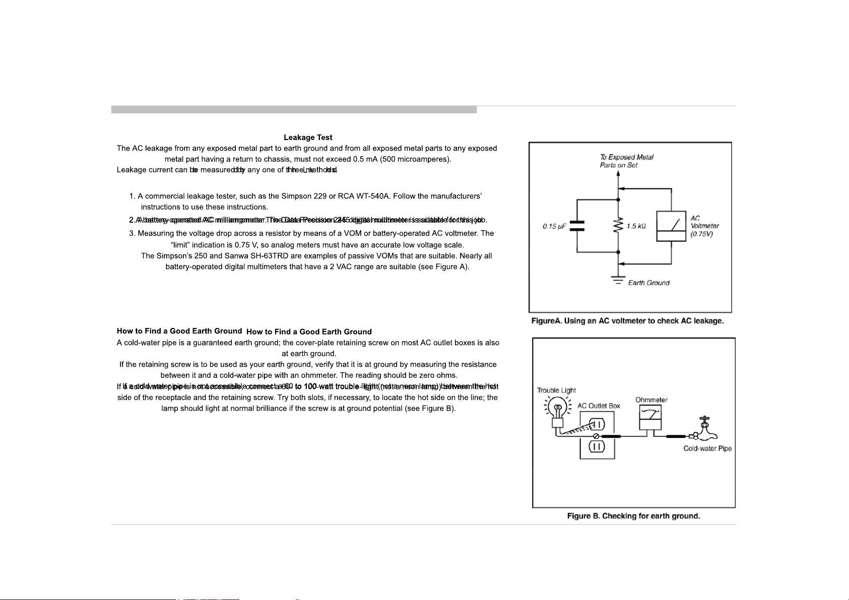
7. Check the antenna terminals, metal trim, “metallized” knobs, screws, and all other exposed metal parts for AC leakage. Check leakage as described below.
8. For safety reasons, repairing the Power board and/or Inverter board is prohibited.
KD-65/85X9500B
6
Page 6
SAFETY CHECK-OUT
KD-65/85X9500B
7
Page 7
The units in this manual contain a self-diagnostic function. If an error occurs, the Smart Core Red LED will automatically begin to flash.
The number of times the LED flashes translates to a probable source of the problem.
A definition of the Smart Core Red LED flash indicators is listed in the instruction manual for the user’s knowledge and reference.
If an error symptom cannot be reproduced, the remote commander can be used to review the failure occurrence data stored in memory to reveal past problems and how often these
problems occur.
DIAGNOSTIC TEST INDICATORS
When an error occurs, the Smart Core Red LED will flash a set number of times to indicate the possible cause of the problem.
If there is more than one error, the LED will identify the first of the problem areas.
Result for all of the following diagnostic items are displayed on screen.
If the screen displays a “0”, no error has occurred .
RED LED b linking coun t Detect ion Items
2x
3x
3x
4x
4x
5x
6x
6x
7x
8x
9x <U>Tuner b oard err or [TU_BOARD]
<G/B> Main 12V failure [MAIN_POWE]
* This fa ilure is not saved
* This fa ilure is not saved.
<B> Main 5. 0/3.3/1.8/ 1.0 failure [DC_ALERT]
* 5.0/1. 0V failures a re not sav ed.
<B/S> Audio amp. prote ction / Audio amp. I2C NACK [AU D_ERR]
<B> HDMI equalizer/switch I2C NACK [HDMI_EQ/HDMI_EQ2/HDMI_EQ3] * T here is Temp. se nsor on th e same I2C bu s
<B/U> Tuner or demodu lator I2C NACK [TU_DEMOD]
<B/U> AFE dev ice I2C NACK [AFE_I2C]
<B/U> AFE dev ice SPI NACK [AFE_ SPI] * only f or AEP,CH
<B> V-by-On e lock monito ring between CXD4746 and NT7232 4[SC_OUT_ERR]
<B> CXD4746 I2C NACK and V-by-O ne lock monito ring between CXD4746 and Ayu2[SC_ ERR]
<B> FW in itialization erro r and I2C NACK for NT723 24[FRCD_I2C]
<L/P> LED driver failu re [LD_ERR]
<L/P> LED voltage er ror [VLED]
<B/T>Tcon d evice initializatio n failure de tection [TC ON_ERR]
<B/T>Tcon d evice I2C communic ation erro r detection [TCON_ERR]
<P/T/G/ B> Panel ID EEPROM I2C NACK (Also panel power failure is a suspect) [ P_ID_ERR]
*PCON_ERR and TG_ERR is n ot used.
<G/P/B> Bac klight failure [BACKLIGHT]
<G/T/P/ B> Backlight con verter OVP [ BACKLIGHT]
Over t emperature protection [TEMP_ERR]
<B> Temp. sen sor I2C NACK [TEMP_ERR] * T here is HDMI Eq on the same I2C b us.
Software Er ror (Also t he main boar dʼs memory or CAM module is a s uspect)
<B> CXD4754 device err or and WDT detection [LYON_ERR]
*Even if d etecting CXD474 5 Device er ror, the set does not g o to safety shutdown (o nly when user uses CXD4754 function, th e set reb oots)
Even if d etecting CXD47 45 Device er ror, the se t does not go to safet y shutdown (o nly when user uses CXD4754 function, the set reb oots)
and n ot flash LED, only recor ds error logs.
<G>: Power supply board, <B>: Main board, <T>: Tcon board, <L>: LED driver (LD) board ,
<P>: Panel module , <S>: Speaker , <A>: Power Adapter, <U> Tuner board
KD-65/85X9500B
8
Page 8
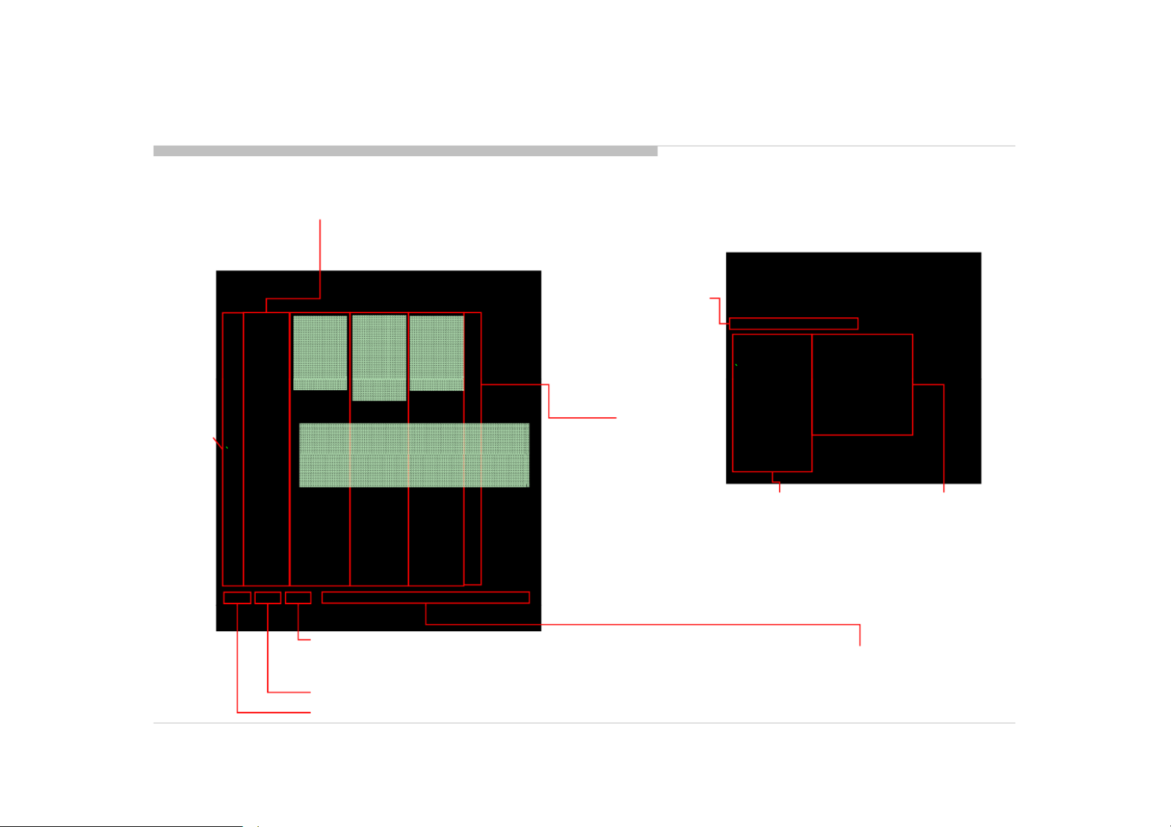
[SELF DIAGNOSTIC SCREEN DISPLAY]
SELF DIAGNOSIS FUNCTION
Smart Core
Red LED
blinking count
g
Error item name
SELF CHECK
002 MAIN_POWE - --- --- ---- - -- --- --- ---- -- ---- --- --- 00
003 AF E_I2C ---- --- --- -- - --- --- ---- - -- --- --- --- - 00
003 DC _ALERT -- ---- --- --- --- --- ---- -- ------- --- -- 0 0
003 AUD_PRO T --- ---- --- -- - --- --- ---- - -- --- --- --- - 00
003 HDMI_EQ ------ ---- -- - --- --- --- -- - ---- --- --- - 00
003 T U_DEMOD ------- --- -- - --- --- --- -- - ---- --- --- - 00
_
003 SC_ OUTERR ---- --- --- -- - --- ---- --- - - ---- --- --- - 00
003 SC_ ERR --- --- ---- -- ------- --- -- - --- --- ---- - 00
003 F RCD_I2C --- --- --- --- --- ---- --- -- - --- --- ---- - 00
003 HDMI_EQ2 ------ --- --- ------ ---- -- ------- --- -- 0 0
003 LYON_ERR ------ --- --- --- --- ---- -- ------- --- -- 0 0
004 VL ED --- --- ---- -- - --- --- --- -- - --- ---- --- - 00
004 L D_ERR 00
005 T CON_ERR --- --- ---- -- - --- --- --- -- - --- ---- --- - 00
005 P_ ID_ERR ------- --- -- - --- ---- --- - -- --- --- ---- 00
005 PCO N_ERR - --- --- --- -- - ---- --- --- - -- --- ---- --- 00
006 BACKL ITE - --- ---- --- - -- --- --- ---- -- ---- --- --- 00
007 T EMP_ERR 1208 23132523 ------ --- --- --- --- ---- -- 0 1
008 VPC WDT ------ ---- -- - --- --- --- -- - --- ---- --- - 00
008 VPC_ WDT --- --- ---- -- ------- --- -- - --- --- ---- - 00
008 MEPS_W DT --- ---- --- -- - --- --- ---- - -- --- --- --- - 00
008 HOST _WDT -- --- ---- --- --- --- --- --- ------- --- -- 0 0
008 ST BY_WDT -- --- --- ---- -- ---- --- --- --- --- ---- -- 0 0
008 AF E_WDT - ---- --- --- - -- --- ---- --- --- --- --- --- 00
009 T U_BOARD ------ --- --- --- ---- --- -- - --- --- ---- - 00
00081 -000671 -00088 0000000 00000000 00570-0 00000000 00000000 132
Error
timestam
p for last
recorded
error
003 AF E SPI
---- --- --- -- - ---- --- --- - -- --- ---- --- 00
003 HDMI_EQ3
---- --- --- -- - ---- --- --- - -- --- ---- --- 00
Format of error timestamps
YYMMDDhhmmss (in UTC)
004 L D ERR
---- --- --- -- - ---- --- --- - -- --- ---- --- 00
Example:
120823132523 -> Aug 23 2012 13:25:23 UTC
* Only when time is set, an error timestamp is saved.
005 T G_ERR
---- --- --- -- - ---- --- --- - -- --- ---- --- 00
007 FAN_ERR
---- --- --- -- - ---- --- --- - -- --- ---- --- 00
*Following error is invalid in RB2.
FAN_ERR
EMIT_ERR
TCON_ERR
Error
timestam
p for
second
last
recorded
recorded
error
Example:
Error
timestam
p for 3rd
last
recorded
error
error
MAC address
of Wi-Fi USB
Error count
Model Name :KDL-RB2T
Serial Numbe r :1000 162
Package Number :PKG0. 410EUA
Device ID :B0:00:0 2:4D:72:88
Wired Ma c
dongle*1.
Wired Mac :D8:D4:3C :A2:EE:9F
Wireles s Mac :34:2 3:87:d4:4 8:a4
USB dongle :N/A
<MAIN> <EXT>
DM0.410 EUA WF :3.5.3.999 9
WF0.3 00W00AA WF:----- ---
DF5.1 37W00AA BT:
YM1 224W 00AA 2 1 14 4 71
YM1.224W 00AA 2.1.14.4 71
M5.503C EFR:03 .01.01.18
(DM0.39 0EUA)
DD0.37 0W00AA
PK0.370 W00AA SCF :50.10
AM0.410W W R OF:---- --- ---- --- ---
MID:2411AB19
PID 0E0420 40
PID:0E0420 40
PNL:YD4S550 LTU010
:D8:D4: 3C:A2:EE:9F
<FS>
Main CPU
information
*1
1
1. When no Wi-Fi USB dongle is connected, NA is displayed.
2. If you insert/disconnect Wi-Fi USB Dongle during Self Diagnosis
Display, press <1> -> <4> on remote commander to refresh Mac
address displayed on “USB dongle”.
- Alternatively, you can re-display Self Diagnosis Display to update the
information.
information.
External module
information
KD-65/85X9500B
Panel operation time by hour
Panel Operation Time is recorded every 30 min, but Total Operation Time is recorded every 1 hr.
Therefore, the panel op. time might become larger than the total op. time.
Boot count
Total operation time by hour
Count of writing to NAND device:
As vfat partition– As ext4 partition
9
Page 9

SELF DIAGNOSIS FUNCTION
For errors with symptoms such as “power sometimes shuts off” or “screen sometimes goes out” that cannot be confirmed, it is possible to bring up past occurrences of failure for
SELF-DIAGNOSTIC SCREEN DISPLAY
confirmation on the screen:
S
[To Bring Up Screen Test]
In standby mode, press buttons on the remote commander sequentially in rapid succession as shown below:
*
: Note that this differs from entering the service mode (volume +)
*
Since the diagnostic results displayed on the screen are not automatically cleared always check the self diagnostic screen
Since the diagnostic results displayed on the screen are not automatically cleared, always check the self-diagnostic screen.
After you have completed the repairs, clear the result display to “0”.
Clearing the Self Check Diagnostic List
1. Error history : Press the Channel 8 => Channel 0 .
2. Panel operation time : Press the Channel 7 => Channel 0 .
Exiting the Self-diagnostic screen
To exit the Self Diagnostic screen, turn off the power to the TV by pressing the POWER button on the remote or the POWER button on the TV.
KD-65/85X9500B
10
Page 10
• There are clutch in the yellow frame[ ]. Therefore please be careful in the case of the disassembly or assembly of parts.
KD-65/85X9500B
11
Page 11

1-1-1. STAND
DISASSEMBLY
KD-65/85X9500B
2 Screws (SCREW, +PSW M5X16) P/N: 2-580-608-01
STAND,RIGHT (2L MIA)
P/N: 4-486-550-02
2 Screws (SCREW, +PSW M5X16) P/N: 2-580-608-01
2
STAND,LEFT (2L MIA)
P/N: 4-486-545-02
1
12
Page 12

1-1-2. CAMERA MODULE EXTERNAL TYPED
DISASSEMBLY
1
Screw (SCREW +PSW M4X10) P/N: 4-159-298-01
KD-65/85X9500B
2
CAMERA MODULE
EXTERNAL TYPED
13
Page 13

1-1-3. COVER, TERMINAL SIDE
DISASSEMBLY
2
31
COVER, TERMINAL SIDE
KD-65/85X9500B
14
Page 14

1-1-4. COVER, TERMINAL REAR
1 3
DISASSEMBLY
2
KD-65/85X9500B
COVER, TERMINAL REAR
15
Page 15

1-1-5. LABEL, REAR TERMINAL/LABEL, SIDE TERMINAL
LABEL REAR TERMINALLABEL, REAR TERMINAL
DISASSEMBLY
LABEL, SIDE TERMINAL
KD-65/85X9500B
16
Page 16

DISASSEMBLY
1-1-6. REAR COVER (2L MIA) A
1
16 Screws (SCREW, +PSW M3X6 STEP) P/N: 4-457-815-02
1 Screw (SCREW, +PSW M4X10) P/N: 4-159-298-01
3 Screws (SCREW, +BVTP 4X12 TYPE2 IT-3) P/N: 2-580-639-01
( , )
4 Screws (SCREW, ORNAMENTAL M6X12) P/N: 4-268-126-02
2
3
REAR COVER (2L MIA) A
CATCH, HOOK N
KD-65/85X9500B
17
Page 17

1-1-7. TAPE
DISASSEMBLY
TAPE
TAPETAPE
TAPE
TAPE
KD-65/85X9500B
18
Page 18

1-1-8. WIRE DRESSING
DISASSEMBLY
KD-65/85X9500B
19
Page 19

1-1-9. TAPE
DISASSEMBLY
TAPE
TAPE
KD-65/85X9500B
20
Page 20

1-1-10. TAPE
TAPE
DISASSEMBLY
TAPE
KD-65/85X9500B
21
Page 21

1-1-11. WIRE DRESSING
DISASSEMBLY
KD-65/85X9500B
22
Page 22

1-1-12. WIRE DRESSING
DISASSEMBLY
KD-65/85X9500B
23
Page 23

DISASSEMBLY
1-1-13. AC INLET ASSY
1
2
3
4
AC INLET ASSY
KD-65/85X9500B
Screw (SCREW, +PSW M3X6 W12) P/N: 4-256-393-11
24
Page 24

1-1-14. AC INLET
DISASSEMBLY
1 2
2 Screws (SCREW (+PSW) (M3X6)) P/N: 2-990-421-41
BRACKET, AC INLET
AC INLET
KD-65/85X9500B
25
Page 25

1-1-15. USB ASSY
1
DISASSEMBLY
2
33
USB ASSY
KD-65/85X9500B
26
Page 26

1-1-16. USB HOLDER, CABLE WITH CONNECTOR (USB) and BRACKET, TOP (MIA)
DISASSEMBLY
BRACKET, TOP (MIA)
2
CABLE WITH CONNECTOR (USB)
USB HOLDER
31
KD-65/85X9500B
27
Page 27

1-1-17. CONNECTOR ASSY
DISASSEMBLY
KD-65/85X9500B
CONNECTOR ASSY, 3P
P/N: 1-846-714-11
CONNECTOR ASSY 20P
P/N: 1-910-109-27
28
Page 28

1-1-18. SWF-SPEAKER BOX ASSY
1 3
DISASSEMBLY
2
SWF-SPEAKER BOX ASSY
KD-65/85X9500B
29
Page 29

1-1-19. SPEAKER BOX ASSY (L)
DISASSEMBLY
2
1
KD-65/85X9500B
3
SPEAKER BOX ASSY (L)
30
Page 30

1-1-20. SPEAKER BOX ASSY (R)
DISASSEMBLY
2
1
KD-65/85X9500B
3
SPEAKER BOX ASSY (R)
31
Page 31

1-1-21. BRACKET, SC(MIA 2L)
1 3
DISASSEMBLY
2
KD-65/85X9500B
2 Screws (SCREW (+PSW) (M3X6)) P/N: 2-990-421-41
BRACKET, SC(MIA 2L)
BRACKET, SC(MIA 2L)
32
Page 32

1-1-22. SMART CORE
DISASSEMBLY
SMART CORE
KD-65/85X9500B
33
Page 33

1-1-23. SWITCH UNIT ASSY
DISASSEMBLY
1
2
S C SSSWITCH UNIT ASSY
KD-65/85X9500B
34
Page 34

1-1-24. HARNESS ASSY (MAIN)
DISASSEMBLY
HARNESS ASSY (MAIN)
P/N: 1-910-109-25
KD-65/85X9500B
35
Page 35

1-1-25. SLIDE, CLAMP
DISASSEMBLY
1
2
SLIDE, CLAMP
KD-65/85X9500B
36
Page 36

1-1-26. SHEET (CORE), C
DISASSEMBLY
SHEET (CORE), CSHEET (CORE), C
KD-65/85X9500B
37
Page 37

1-1-27. TAPE (DK020FR-19) 19X70 SHEET
DISASSEMBLY
KD-65/85X9500B
TAPE (DK020FR-19)
19X70 SHEET
38
Page 38

1-1-28. BRACKET, SWF (2L MIA)
1 3
DISASSEMBLY
2
KD-65/85X9500B
BRACKET, SWF (2L MIA)
6 Screws (SCREW, +PSW M3X6 W12) P/N: 4-256-393-11
39
Page 39

DISASSEMBLY
1-1-29. HOLDER, SIDE SW (MIA)
1 2 4
3
HOLDER, SIDE SW (MIA)
Screw (SCREW (+PSW) (M3X6)) P/N: 2-990-421-41
KD-65/85X9500B
40
Page 40

1-1-30. WIRE DRESSING
DISASSEMBLY
KD-65/85X9500B
41
Page 41

1-1-31. CONNECTOR ASSY AND HARNESS ASSY
CONNECTOR ASSY 28P
P/N: 1-910-109-24
DISASSEMBLY
HARNESS ASSY
P/N: 1-910-109-26
KD-65/85X9500B
42
Page 42

1-1-32. BRACKET, STAND (MIA)
DISASSEMBLY
2
31
BRACKET STAND (MIA)
BRACKET, STAND (MIA)
KD-65/85X9500B
Don’t put the bracket on the dowel.
p
4 Screws (SCREW, +PSW M4X10) P/N: 4-159-298-01
43
Page 43

DISASSEMBLY
1-1-33. BRACKET, RL (MIA)
1 4
2
3
BRACKET RL (MIA)
BRACKET, RL (MIA)
KD-65/85X9500B
2 Screws (SCREW, +PSW M4X10) P/N: 4-159-298-01
44
Page 44

1-1-34. BRACKET, VESA (MIA)
1
DISASSEMBLY
2
3
KD-65/85X9500B
4
BRACKET, VESA (MIA)
4 Screws (SCREW, +PSW M4X10) P/N: 4-159-298-01
45
Page 45

1-1-35. FLEXIBLE FLAT CABLE
DISASSEMBLY
FLEXIBLE FLAT CABLE 30P
P/N: 1-910-109-29
FLEXIBLE FLAT CABLE 20P
P/N: 1-910-109-19
KD-65/85X9500B
46
Page 46

1-1-36. TAPE
DISASSEMBLY
TAPE
KD-65/85X9500B
TAPETAPE
47
Page 47

1-1-37. FLEXIBLE FLAT CABLE
DISASSEMBLY
FLEXIBLE FLAT CABLE(41P)
P/N: 1-848-310-11
FLEXIBLE FLAT CABLE 51P (HX65)
P/N: 1-848-311-11
KD-65/85X9500B
48
Page 48

1-1-38. BRACKET, SIDE (MOLD)
DISASSEMBLY
1
2
BRACKET, SIDE (MOLD)
KD-65/85X9500B
49
Page 49

DISASSEMBLY
1-1-39. PLATE, MAIN (MIA) ASSY
1
2
3
4
PLATE, MAIN (MIA) ASSY
KD-65/85X9500B
8 Screws (SCREW +PSW M3X6 W12) P/N: 4-256-393-11
50
Page 50

DISASSEMBLY
1-1-40. K0
1
2
3
K0
KD-65/85X9500B
4 Screws (SCREW (+PSW) (M3X6)) P/N: 2-990-421-41
51
Page 51

1-1-41. TUS
1 2 3
DISASSEMBLY
TUS
KD-65/85X9500B
4 Screws (SCREW +PSW M3X6 W12)
4 Screws (SCREW +PSW M3X6 W12)
P/N: 4-256-393-11
52
Page 52

DISASSEMBLY
1-1-42. BAXF
1
BAXF
2 3
KD-65/85X9500B
7 Screws (SCREW +PSW M3X6) P/N: 2-990-421-41
53
Page 53

1-1-43. SHEET, THERMAL (BAF)/SHEET, THERMAL (EU TU)/SPACER (G A)
SHEET THERMAL (EU TU)
SHEET, THERMAL (EU TU)
DISASSEMBLY
SHEET, THERMAL (BAF)
KD-65/85X9500B
SPACER (G A)
54
Page 54

1-1-44. GASKET(TU)
DISASSEMBLY
GASKET(TU)
KD-65/85X9500B
55
Page 55

1-1-45. G3
DISASSEMBLY
2
1
5 Screws (SCREW +PSW M3X6 W12) P/N: 4-256-393-11
KD-65/85X9500B
3
G3
56
Page 56

1-1-46. G4B
1
DISASSEMBLY
2
3
5 Screws (SCREW +PSW M3X6 W12) P/N: 4-256-393-11
KD-65/85X9500B
G4B
57
Page 57

1-1-47. SPACER
DISASSEMBLY
KD-65/85X9500B
58
Page 58

1-1-48. SHEET, INSULATION (G34)
DISASSEMBLY
1 21 2
SHEET, INSULATION (G34)
KD-65/85X9500B
59
Page 59

1-1-49. LCD PANEL
DISASSEMBLY
LCD PANELLCD PANEL
KD-65/85X9500B
60
Page 60

1-2-1. LIGHT CASE ASSY
1
DISASSEMBLY
2
LIGHT CASE ASSY
KD-65/85X9500B
61
Page 61

1-2-2. BACK COVER (M)
DISASSEMBLY
2
3
BACK COVER (M)
41
KD-65/85X9500B
Screw (SCREW +BVTP 4X12 TYPE2 IT-3) P/N: 2-580-639-01
62
Page 62

1-2-3. MIC UNIT
1 2
DISASSEMBLY
MIC UNIT
KD-65/85X9500B
63
Page 63

1-2-4. BT MODULE
DISASSEMBLY
1 2
KD-65/85X9500B
BT MODULE
64
Page 64

1-2-5. WIRELESS LAN CARD
1 3
DISASSEMBLY
2
WIRELESS LAN CARD
KD-65/85X9500B
65
Page 65

1-2-6. FRONT COVER (M)
DISASSEMBLY
FRONT COVER (M)
KD-65/85X9500B
66
Page 66

1-2-7. TOP COVER (L)
DISASSEMBLY
1
2
3
TOP COVER (L)
KD-65/85X9500B
67
Page 67

1-2-8. HSC2-M BOARD
DISASSEMBLY
1
2
3
KD-65/85X9500B
HSC2-M BOARD
68
Page 68

1-2-9. BOTTOM CASE (LL) A
DISASSEMBLY
BOTTOM CASE (LL) A
KD-65/85X9500B
69
Page 69

HOW TO ENTERING SERVICE MODE
1) Turn on the main power switch to place this set in standby mode.
2) Press the buttons on the remote commander as follows, and entering service mode.
3) Service mode display.
Note: First of all when you enter Service Mode you can see “Digital” service modeNote: First of all, when you enter Service Mode, you can see Digital service mode.
Whenever you press “OPTIONS” on remote, each service mode is changed.
“Digital” -> “Chassis” -> “VPC”
KD-65/85X9500B
70
Page 70

4) How to use the remote commander.
5) After entering service mode then turn off the power switch5) After entering service mode, then turn off the power switch.
ADJUSTMENT
KD-65/85X9500B
71
Page 71

CHANGE DATA
Note: “Digital” service mode don’t have to Save ( except “002 MODEL”)Note: Digital service mode don t have to Save. ( except 002 MODEL )
1) Change Data of “Digital” service mode. ( except “003 DIG_SRV_MODE” category)
a. Press “2 / 5” on remote to select (up / down) category.
b. Press “1 / 4” on remote to select (up / down) Item.
c. Press “3 / 6” on remote change (up / down) data.
ADJUSTMENT
KD-65/85X9500B
72
Page 72

2) Change Data of “Digital” service mode. ( “003 DIG_SRV_MODE” category)
“003 DIG SRV MODE” i t f “Di it l” i d“003 DIG_SRV_MODE” is one category of “Digital” service mode.
Please note because this operation is special.
a. Press “2 / 5” on remote to select “003 DIG_SRV_MODE”.
b. Press “1 / 4” on remote to select (up / down) Item.
c. Press “0 / 10” on remote to select item.
d. Press number key “1”~”9” directly. “*” stamp move.
e. Press “12 / enter / select” to decide and advance next step. Press “return”, when returning on the
previous page.p p g
ADJUSTMENT
KD-65/85X9500B
73
Page 73

SAVE CHANGING DATA 1 (Only when B* board is replaced)
1) In “Digital” service mode1) In Digital service mode
( “002 MODEL” category)
000 SEGSelect segment information
001 DEST Select destination information
l d l002 MODELNAME Select Model Name
003 SERIAL Can be set Only Once for the new board
005 VAR_TYPE Select variable information
a. Change data for each model.
b. Press “Mute” , “0” on remote sequentially . Red “ WRITE ” is shown. This indicates writing is in process.
c. After a while, red “ WRITE ” disappears. Green Done will be displayed for a while, which means writing process is done.
d. For the items SEG, DEST, MODELNAME and VAR_TYPE,
after changing each item service save (“mute”+”0”) isafter changing each item, service save ( mute + 0 ) is
required. For the item SERIAL, after inputting the serial
number, press key “12” or “Enter” to save the data.
– Please save the items according to the sequence “SEG ->
DEST -> MODELNAME ->VAR_TYPE”
– When Saving the item "SEG", sometimes instead of "Writing",
the word "Pending" will appear. In this case, skip "SEG",
saving "DEST“, "MODELNAME“ and “VAR_TYPE” is OK.
ADJUSTMENT
KD-65/85X9500B
Note : Please refer “RB2G WW Service Update Procedure for
Panel, Board and Software” (manual P/N 9-888-155- ) in TISS for
details
details.
74
Page 74

SAVE CHANGING DATA 2
1) Write data for “Chassis” or “VPC” service mode1) Write data for Chassis or VPC service mode
a. Press “Mute” on remote.
It shows green “ SERVICE ” changes to green “ WRITE ”.
b. Press “0” or “enter” on remote. Green “ WRITE ” changes to red “ WRITE ”. It indicate writing is processing.
c. After a while, red “ WRITE ” changes to green “ SERVICE ”. Writing process is done at this point.
2) TV reboot is necessary for applying data change.
ADJUSTMENT
KD-65/85X9500B
75
Page 75

WHITE BALANCE ADJUSTMENT
Note: Please execute this adjustment if necessaryNote: Please execute this adjustment if necessary.
Change Data of “VPC” service mode. ( “003 WB” category)
a. Press “1” or “4” on remote to select WB adjustment menu.
b. Change data by pressing “3” or “6”. Each range of these items is 0~1023.
c. Press “mute” +”0” on remote to save the data.
“SERVICE” comment is changed to “ WRITE ”, indicating writing process.
d. After a while, “ WRITE ” comment returns to “SERVICE”, which means writing process is done..
ADJUSTMENT
KD-65/85X9500B
76
Page 76

SET TO SHIPPING CONDITION
H t d hi i ditiHow to do shipping condition.
a. Move to “Digital” service mode.
b. Press “8” on remote. It shows green “ SERVICE ” changes to green “ RST- ”.
c. Press “mute” on remote. Added green “ EXE ” after green “ RST- ” .
d. Press “0” on remote. Green “ EXE-RST ” changes to red “ EXE-RST ”. It indicate writing is processing.
e. After a while, red “ EXE-RST ” changes to green “ SERVICE ”.
f. And BLINK Smart Core WHITE LED. Writing process is done at this point.
SONY
<Another way>
You can set to shipping condition w/o entering Service Mode.
-> “Cursor Up” on remote + “Power Key” on TV.
ADJUSTMENT
KD-65/85X9500B
77
Page 77

RED DOT: Most likely defective part
BLUE TRIANGLE: Secondary possible defective part
BLACK TEXT: Board that may correct the symptom
Refere nce
B* Board
TU board
K* Board
G* Board
H* BoardH* Board
Speaker
Camera Module
Mic. Module
Wifi Module
BT Module
LD* Board
LVDS FFC
Tcon
LCD Panel
Problem
Symptoms - Shutdown. Power LED
blinking red diagnostics sequences
2 3 4 5 6 7 8 9 10
Power Power LD
Audio
Local
I2C
4K
unique
(Rogue/(Rogue/
Scorpio/
4K FRC
Panel
(Tcon)
Panel
(Backlig
ht) TEMP
Soft-
ware
No
Power
No White
Power LED
& does not
response to
response to
remote (Dead
Set)
- missing or distorted
Stationary
colour lines
d t
or dots Inputs
Video
No video
One of
I t
No video
all Inputs
all Inputs
Remote Ne twork Audio Skype Smart Core
No
Remote
(IR RC)
(IR RC) connect
Wireless
can't tNo Audio
Skype
Can't Work
Can t Work
Smart Core no
LED (Set is still
li )
alive)
Bluetooth
(BT)
Bluetooth /
One Step
Remote
(OSR) 't
(OSR) can't
connect
KD-65/85X9500B
78
Page 78

No Power
TROUBLE SHOOTING
KD-65/85X9500B
Check STBY 3.3V
L9700 or C9707
OK
B* Board
NG
Replace
Between G* Board to
B* Board Harness
B Board Harness
OK
Harness
DC/DC converter check
NG
G* Board
79
Page 79

1) DC/DC converter check
START
TROUBLE SHOOTING
KD-65/85X9500B
Check C9159, 9161
or C9163 Voltage.
Is the voltage 1V?
yes
Check C9158
or C9160 Voltage.
Is the voltage 5V?
Is the voltage 5V?
yes
Check C9120 Voltage.
Is the voltage 3.3V?
yes
Check C9153 Voltage.
Is the voltage 1.5V?
yes
no
Check F9105
Check C9168
is it 1.18V?
no
Check F9106
yes
no
no
no
Check F9104
Check F9102
Check F9102
Check F9102
END
80
Page 80

1) 3 times blinking (DC Alert & Communication Error)
TROUBLE SHOOTING
3-time blinking
Check D+1.0V
at JL9129 on
the B* Board
OK
OK
Check
+3.3V_MAIN_1
at JL9116 on
the B* Board
the B Board
OK
Check
Check
+1.8V_MAIN on
Pin 2 of IC9201
OK
Check
+5.0V_MAIN
at JL9132on
the B* Board
NG
NG
NG
NG
NG
DC_ALERT
F9105,IC9103,
etc (B* Board)
F9102,IC9102,
etc (B* Board)
IC9201,etc
(B* Board)
F9104 / IC9101
,etc (B* Board)
DMD_TU_I2C
or I2CB bus check:
Probe CL2101,
CL2102 / CL2318
CL2102 / CL2318,
CL2101 on
TU* Board
OK
SPIC check
Probe RB8522
OK
I2C_CCP check
R8502 and R8506 /
R8507 and R8508
OK
I2CA bus check:
Probe CL5069,
CL5072
OK
O
TUNER
NG
I2C bus dumping or
Brownie
NG
NG
NG
AYU2
AYU2
SPI
dumping
resistor
or AYU2
I2C_CCP
Pull Up
Pull Up
I2CA b
I2CA bus
dumping
resistor
or AYU2
Or FW of
IC5605 is
broken
broken
I2CD bus check:
Probe CL5423,
CL5428
OK
I2CC bus check:
I2CC bus check:
Probe CL3371,
CL3372
OK
V-by-One check:
Probe CL8064,
CL8066, R6020
HDMI
NG
BackEnd
NG
NG
NG
I2CD bus
Dumping resistor
or Ayu2
or FW of IC3150
is broken
I2CC bus
dumping
dumping
resistor
or AYU2
or Scorpio
/FRC
VBO
dumping
resistor and
capacitor
or AYU2
or Scorpio
/FRC
Check
Speaker
Speaker
Impedance
at
SP
Connector
OK
Check
Audio +12.5V
at pin 18/20
of CN9101
on the B* Board
(except Adapter
model)
OK
Check
+12.5V / +19.5V
at Power Amp
side of F4401
/ F4601 on
the B* Board
OK
IC4901 / IC4601
,etc
(B* Board)
NG
NG
NG
AUDIO
Speaker
G* Board
F4401/F4601,
IC4901/IC4601
,etc
(B* Board)
KD-65/85X9500B
81
Page 81

2) 3 times blinking (Audio Error)
(Audio amp. error
detection.
or Audio amp. I2C o ud o a p C
communication error
detection.)
TROUBLE SHOOTING
KD-65/85X9500B
3-4-2. No Sound Power Off Check
G tGo to
Go to
3-4-3. No Sound Power On Check
82
Page 82

3) 4 times blinking (LED Voltage Error)
TROUBLE SHOOTING
KD-65/85X9500B
83
Page 83

4) 5 times blinking (T-Con Error)
TROUBLE SHOOTING
KD-65/85X9500B
84
Page 84

5) 6 times blinking (Backlight Error)
TROUBLE SHOOTING
KD-65/85X9500B
85
Page 85

6) 7 times blinking (Temperature Error)
7-time blinking
TROUBLE SHOOTING
KD-65/85X9500B
Setting
circumstance is OK?
Temperature,
Ventilation, etc.
Yes
Change B* Board
Change B* Board,
and Aging a few
hours
Symptom
improvement
improvement
B* Board
No
NG
NG
I2CA bus dumping or
Ayu2 / Ayu2L check
Set to another
location, etc.
Panel
I2CA bus check:
HDMI is working?
No
No
Yes
Temp sensor
IC7001
86
Page 86

No Sound
Without LED 3x
[S k ] tti i
[Speakers] setting is
[Audio System] ?
Yes
Yes
Ch th tti t
Change the setting to
[TV Speakers]
No sound only
Analog RF and
Digital RF ?
No
No
Yes
TROUBLE SHOOTING
Tuner relation issue
KD-65/85X9500B
No
AV receiver is
connected
to HDMI in ?
No
Headphone is connected to
HP/Audio Out terminal ?
NNo
→
[Sound]
[Headphone Speaker Link]
setting is [On] ?
No
Go to
3-4-2. No Sound
Power Off Check
Yes
Select [External Inputs]
[BRAVIA Sync Settings]
[BRAVIA Sync Control]
Yes
Disconnect the Headphone
Change [Sound]
[Headphone Speaker Link]
Yes
HP/Audio out terminal or Headphone
→
→[off]
→
to [Off], OK ?
Replace B-PWB
detect GPIO may be broken
No sound only HDMI ?
→
No
Yes
HDMI relation issue
Go to
3-4-1. No Sound Audio
87
Page 87

3-4-1. No Sound Audio
No Sound
TROUBLE SHOOTING
Audio
From 3-4
KD-65/85X9500B
Replace B-K Harness
Yes
OK ?
No
Replace K-PWB
OK ?
(check / diagnose K-PWB itself before replace.
See next page.)
See next page )
No
Replace B-PWB
Yes
OK ?
No
Finish
Yes
Finish
88
Page 88

3-4-2. No Sound Power Off Check
TROUBLE SHOOTING
Power Off Check
From 3-3 or 3-4
(1) K-PWB
PVDD-GND short ?
(See APPENDIX-5)
No
(2) K-PWB
LDO out short ?
(See APPENDIX-5)
No
(3) K-PWB
Fuse broken ?
(See APPENDIX--5)
No
Yes
Yes
Yes
Yes
Replace K-PWB
Power Off Check
From 3-4
Measure the Speaker
impedance by multi meter
impedance by multi-meter
Less than 3
Ω ?
No
Confirm the speaker
harness
Cut or shorted
to the chassis ?
No
Return to 3-3 or 3-4
Yes
Yes
Replace Speaker
Replace Speaker
Replace Speaker Harness
KD-65/85X9500B
89
Page 89

3-4-3. No Sound Power On Check
Power On Check
From 3-3
TROUBLE SHOOTING
(4) 12.5V check
12.5V is supplied to
K-PWB for a moment
before LED 3x blinking ?
No
Replace G-K Harness
OK ?
OK ?
No
Replace G-PWB
OK ?
No
No
Return to 3-3
Yes
Yes
Yes
Measure voltage between PVDD and GND at capacitor C4341,
(4) 12.5V check K1-PWB (HJ)
C4342, C4441 or C4442. (See 3.3)
Voltage rise more than 0V for a moment at power on
→ Yes
Finish
KD-65/85X9500B
90
Page 90

3-4-4. No Sound Audio HP/Audio out
TROUBLE SHOOTING
No Sound Audio
HP/Audio out
KD-65/85X9500B
Headphone Volume
is set to MIN?
No
Replace B-PWB
[Headphone]
Yes
[Sound]
→
[Headphone/Audio out]
is set to ?
[Audio Out]
Increase Headphone VolumeReplace B PWB Increase Headphone Volume
[Subwoofer]
Set [Headphone/Audio Out]
to [Headphone] or [Audio Out]
Replace B-PWB
91
Page 91

No Picture
TROUBLE SHOOTING
KD-65/85X9500B
All blue picture is on?
(Factory SW
is booted )
is booted.)
Yes
B* Board
No
Check the G*- LD*
Harness
NG
OK
the B-Tcon, B-LD*
Symptom
improvement
B-Tcon, B-LD*
Symptom
improvement
Replace
FFC
FFC
Change G* Board
G* Board
NG
Change B* Board
Symptom
improvement
NG
B* BoardHarness
LCD Panel
(T con LD* )
(T-con, LD )
NG
92
Page 92

1) EXT. Analog Video/Component Input
Video 1 Video 2 Component
No Picture No Picture
TROUBLE SHOOTING
No Picture
KD-65/85X9500B
Check if input OSD
is GREY OUT
OK
Check wave between
C3000 and IC9001
OK
OK
Confirm Analog RF
input wor king
OK
Brownie [IC90 01]
Brownie [IC90 01]
Problem
NG
Check J3101
VIDEOA_DET
NG
Detailed check
J3101 sign al path
Detaile d SDIF path
Check b etween
IC9001 a nd IC9000
NG
Check signal
between IC9001 and
IC9000 [R 8652]
Ayu2 [IC900 0]
y [ ]
Change B* board
conne ction,
Proble m
NG
Check J3104
Check if input OSD
is GREY OUT
OK
Check wave between
C3018 and IC9001
OK
OK
NG
Confir m Analo g RF
input wor king
OK
OK
Brownie [IC90 01]
Brownie [IC90 01]
Proble m
Conne ction,
VIDEOB_DET
NG
Detailed check
J3104 sign al path
Detailed SDIF path
Check b etween
IC9001 a nd IC9000
G
NG
Check s ignal
between IC9001 and
IC9000 [R 8652]
Ayu2 [IC900 0]
At C802 5
At C802 5
Problem
NG
OK
Check if input OSD
is GREY OUT
OK
Check wave
Between C3 018/C3019
and IC90 01
OK
OK
Confirm HDMI
input wor king
OK
Confirm other ana log
Input workin g
OK
Brownie [IC90 01]
Proble m
Check J3104
NG
VIDEOB_DET a t
NG
Detailed check
J3104 signal pa th
NG
HDMI EQ [IC5009]
Detaile d TMDS path
check between
IC9001 a nd IC5009
NG
Check s ignal
between IC9001 and
between IC9001 and
IC5009 [R B5008]
Ayu2 [IC900 0]
Conn
C8025 ,
CR DET at
CR_DET at
C8014
Proble m
Proble m
NG
OK
93
Page 93

TROUBLE SHOOTING
Side Key button
malfunction
Change Switch Unit
NG
Harness on Switch Unit
and B* Board properly connected
and B Board properly connected
NG
Change
Switch unit-B* board Harness
NG
Change B* Board
OK
OK
OK
Switch unit issue
Harness connection
issue
issue
Harness issue
Harness issue
KD-65/85X9500B
94
Page 94

TROUBLE SHOOTING
IR do not response to
Remote Commander
Center white LED
lit up when remote is
control is pressed
OK
Harness on H-
board and B* Board
properly connected
NG
Change
Change
H-B* board Harness
NG
Change Smart Core
NG
Change B* Board
NG
Check whether center
white LED blink ,when using
commander near the
sensor windows
OK
OK
OK
OK
Harness connection
H B* board harness
H-B board harness
Smart core issue
i
issue
issue
NG
NG
OK
Remote control battery
could be weak.
Change battery.
KD-65/85X9500B
95
Page 95

TROUBLE SHOOTING
Backlight doesn’t change
when ambient lighting
level changed
Check UI setting for light
Sensor. Make sure it is “on”
Change the UI
setting to “:ON”
NG
NG
Harness on H-board and
B* Board
properly connected
NG
NG
Change
H-B* board Harness
NG
Change Smart Core
NG
Change B* Board
OK
User did not activate light
sensor function
OK
OK
Harness connection
H-B* board harness
OK
Smart Core issue
issue
issue
KD-65/85X9500B
96
Page 96

[Network Set-up]
>[Wired Set-up]
on the TV
TROUBLE SHOOTING
KD-65/85X9500B
Connection Results
Connection Results
Cable Connection
Failed Failed
OK
OK
Check cable B board
IP address setting
IP address setting
Manual
Ethernet Cable
Check IP address
Local router setting
Local Access
Wired Set-up
&NG&
OK
Auto
Check
Local router
DHCP server
Connection Results
Internet Access
Failed
Proxy setting
OK
B board
97
Page 97

Wireless Network
on the TV
TROUBLE SHOOTING
Error Message appear
when the Wireless
Network is selected?
Check harness
connection is OK
between WiFi and Bxx
OK
Change
Wi-Fi module
OK
Wi Fi module
Wi-Fi module Main Harness
No
NG
NG
NG NG
Is the radio field
Strength too weak
Strength too weak Bxx Board
or even No signal?
YesYes
Ch WiFi d l
Change WiFi module
OK
WiFi module
Connect properly
No
NG
OK
Change harness
between Bxx board
and WiFi
Loose harness
and WiFi
Main Harness
oa d
OK
Access Point
Access Point
Change Bxx board
If Wi-Fi malfunction happens,
• Harness between WiFi and Bxx
• Bxx board are suspected.
•
Wi-Fi module
KD-65/85X9500B
98
Page 98

Touch pad Remote doesn’t work
Touch pad Remote doesn t work
Or
One touch remote doesn’t work
Or
3D-glasses (Active) doesn’t work
BT version check
in Service Menu
Ver = --------
Check harness
connection is OK
between BT and Bxx
Ver info.
can be read
NG
Connect properly
Confirm
Touch pad Remote malfunction trouble shooting flow
Or
One touch remote doesn’t work
Or
Or
3D-glasses (Active) malfunction trouble shooting flow
OK
L h
Loose harness
TROUBLE SHOOTING
Service Menu
001 OP
000 VERS
000 VERS
<MAIN> <EXT>
DM0.001JPA WF: 3.0.0.1021
WF0.300W00AA WF: -------DF2.070W00AA FD: 0.003
YM0.619W00AA BT:
M4.922C 2.1.14.470
(DM0.0J00AA)
DD0.320W00AA
BT Version info.
PK0.320W00AA EFR:----------AM0 030JP
AM0.030JP
MID: 04A3B50F
PID: 0F051040
PNL:
DQ3Y400LN0101
Q
OK
Change BT module
OK
OK
BT module
KD-65/85X9500B
NG
NG
Change harness
Between Bxx board
and BT
OK
OK
Main Harness
NG
Change Bxx board
If Bluetooth malfunction happens,
BT module
• Harness between BT module and Bxx
•
a ess bet ee odu e a d
• Bxx board are suspected.
99
Page 99

*(2) BT Active 3D glasses doesn’t work(2) BT Active 3D glasses doesn t work
<2 8V
Ch k 3D Gl
Check 3D-Glasses
<2.8V
Battery voltage is
>2.8V?
Restart TV. Power-off 3D-Glasses
and TRY registration again with 50cm
distance.
Cannot Register
Registered
Registered
Replace to New Battery and try again.
(use CR2025 only.)
Interference from other devices.
TROUBLE SHOOTING
Check if 2.4GHz devices are used or not?
(ex. WiFi, other bluetooth devices, microwave,
cordless phone,....)
Check another 3D-Glasses and re-
register.
OK
3D-Glasses NG.
KD-65/85X9500B
NG
Change to another
environment and try
i t ti i
registration again.
OK
Very strong interference on that spot.
NG
Confirm BT (Bluetooth) malfunction
trouble shooting flow.
g
100
Page 100

TROUBLE SHOOTING
Camera function doesn’t
work well
Self pic?
Far-end pic?
Self pic
Self pic
Check camera direction.
Camera module is set
properly or not.
Far-end pic
Check Video Call
Check self pic by push
“Social Viewing” key.
Update SW
version to latest.
RC OFF/ON
Change Camera module
Change Harness
Change B*Board
Far-end user needs
to prepare Camera
device or unmute
camera function
Camera module issue
Harness issue
Far-end issue
KD-65/85X9500B
101
 Loading...