

Page 1
HISTORY INFORMATION FOR THE FOLLOWING MANUAL:
SERVICE MANUAL
ORIGINAL MANUAL ISSUE DATE: 7/2015
Version Date Subject
1.0 7/2015 Original manual issue.
GN1T CHASSIS
Segment: XC
LCD TV
9-888-578-01
Page 2

SERVICE MANUAL
GN1T CHASSIS
Segment: XC
LCD TV
9-888-578-01
Page 3

MODEL LIST
MODEL COLOR COMMANDER DEST.
KD-55S8500C Black RMF-TX100C CHINA
RMT-TX100C
KD-65S8500C Black RMF-TX100C CHINA
RMT-TX100C
MODEL COLOR COMMANDER DEST.
KD-55/65S8500C(CH)
3
Page 4

WARNINGS AND CAUTIONS - ENGLISH
CAUTION
These servicing instructions are for use by qualified service personnel only.
To reduce the risk of electric shock, do not perform any servicing other than that contained in the operating instructions unless you are qualified to do so.
WARNING!!
An isolation transformer should be used during any service to avoid possible shock hazard, because of live chassis.
The chassis of this receiver is directly connected to the ac power line.
CARRYING THE TV
Be sure to follow these guidelines to protect your property and avoid causing serious injury.
• Carry the TV with an adequate number of people; larger size TVs require two or more people.
• Correct hand placement while carrying the TV is very important for safety and to avoid damages.
SAFETY-RELATED COMPONENT WARNING!!
Components identified by shading and ! mark on the schematic diagrams, exploded views, and in the parts list are critical for safe operation. Replace these components with Sony
parts whose part numbers appear as shown in this manual or in supplements published by Sony. Circuit adjustments that are critical for safe operation are identified in this manual.
Follow these procedures whenever critical components are replaced or improper operation is suspected.
CAUTION ABOUT THE LITHIUM BATTERY
• Danger of explosion if battery is incorrectly replaced. Replace only with the same or equivalent type.
• Outer case broken battery should not contact to water.
KD-55/65S8500C(CH)
4
Page 5

USE CAUTION WHEN HANDLING THE LCD PANEL
When repairing the LCD panel, be sure you are grounded by using a wrist band.
When repairing the LCD panel on the wall, the LCD panel must be secured using the 4 mounting holes on the rear cover.
1) Do not press on the panel or frame edge to avoid the risk of electric shock.
2) Do not scratch or press on the panel with any sharp objects.
3) Do not leave the module in high temperatures or in areas of high humidity for an extended period of time.
4) Do not expose the LCD panel to direct sunlight.
5) Avoid contact with water. It may cause a short circuit within the module.
6) Disconnect the AC power when replacing the backlight (CCFL) or inverter circuit. (High voltage occurs at the inverter circuit at 650Vrms.)
7) Always clean the LCD panel with a soft cloth material.
8) Use care when handling the wires or connectors of the inverter circuit. Damaging the wires may cause a short.
9) Protect the panel from ESD to avoid damaging the electronic circuit (C-MOS).
10) It is recommended not to exceed 1 hour of Power-On nor Burn-in period with LCD panel face down condition, in repair activity.
WARNINGS AND CAUTIONS
KD-55/65S8500C(CH)
5
Page 6

SAFETY CHECK-OUT
After correcting the original service problem, perform the following safety checks before releasing the set to the customer:
1. Check the area of your repair for unsoldered or poorly soldered connections. Check the entire board surface for solder splashes and bridges.
2. Check the interboard wiring to ensure that no wires are “pinched” or touching high-wattage resistors.
3. Check that all control knobs, shields, covers, ground straps, and mounting hardware have been replaced. Be absolutely certain that you have replaced all the insulators.
4. Look for unauthorized replacement parts, particularly transistors, that were installed during a previous repair. Point them out to the customer and recommend their replacement.
5. Look for parts which, though functioning, show obvious signs of deterioration. Point them out to the customer and recommend their replacement.
6. Check the line cords for cracks and abrasion. Recommend the replacement of any such line cord to the customer.
7. Check the antenna terminals, metal trim, “metallized” knobs, screws, and all other exposed metal parts for AC leakage. Check leakage as described below.
8. For safety reasons, repairing the Power board and/or Inverter board is prohibited.
KD-55/65S8500C(CH)
6
Page 7
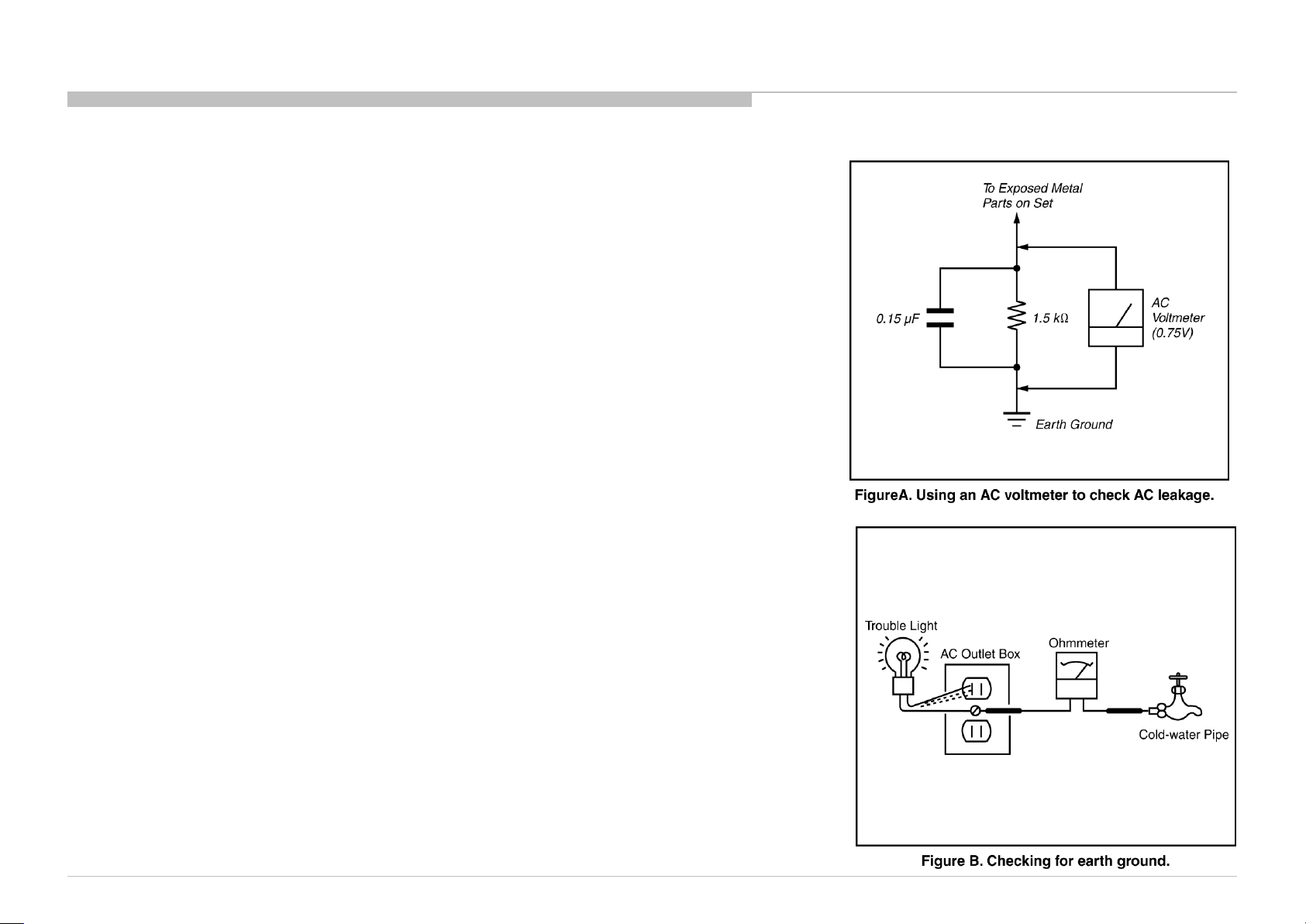
Leakage Test
The AC leakage from any exposed metal part to earth ground and from all exposed metal parts to any exposed
metal part having a return to chassis, must not exceed 0.5 mA (500 microamperes).
Leakage current can be measured by any one of three methods.
1. A commercial leakage tester, such as the Simpson 229 or RCA WT-540A. Follow the manufacturers’
instructions to use these instructions.
2. A battery-operated AC milliampmeter. The Data Precision 245 digital multimeter is suitable for this job.
3. Measuring the voltage drop across a resistor by means of a VOM or battery-operated AC voltmeter. The
“limit” indication is 0.75 V, so analog meters must have an accurate low voltage scale.
The Simpson’s 250 and Sanwa SH-63TRD are examples of passive VOMs that are suitable. Nearly all
battery-operated digital multimeters that have a 2 VAC range are suitable (see Figure A).
How to Find a Good Earth Ground
A cold-water pipe is a guaranteed earth ground; the cover-plate retaining screw on most AC outlet boxes is also
at earth ground.
If the retaining screw is to be used as your earth ground, verify that it is at ground by measuring the resistance
between it and a cold-water pipe with an ohmmeter. The reading should be zero ohms.
If a cold-water pipe is not accessible, connect a 60- to 100-watt trouble- light (not a neon lamp) between the hot
side of the receptacle and the retaining screw. Try both slots, if necessary, to locate the hot side on the line; the
lamp should light at normal brilliance if the screw is at ground potential (see Figure B).
SAFETY CHECK-OUT
KD-55/65S8500C(CH)
7
Page 8
SELF DIAGNOSIS FUNCTION
The units in this manual contain a self-diagnostic function. If an error occurs, the Smart Core Red LED will automatically begin to flash.
The number of times the LED flashes translates to a probable source of the problem.
A definition of the Smart Core Red LED flash indicators is listed in the instruction manual for the user’s knowledge and reference.
If an error symptom cannot be reproduced, the remote commander can be used to review the failure occurrence data stored in memory to reveal past problems and how often these
problems occur.
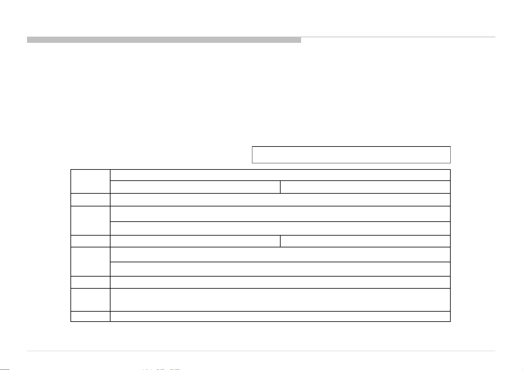
DIAGNOSTIC TEST INDICATORS
When an error occurs, the Smart Core Red LED will flash a set number of times to indicate the possible cause of the problem.
If there is more than one error, the LED will identify the first of the problem areas.
Result for all of the following diagnostic items are displayed on screen.
If the screen displays a “0”, no error has occurred .
<G>: Power supply board, <B>: Main board, <T>: Tcon board, (LD) board ,
<P>: Panel module , <S>: Speaker
RED LED
blinking count
2x <G/B> Main 12V over voltage [MAIN_POWER]
<B> Main 5.0V failure [DC_ALERT]
3x
<B/S> Audio amp. protection [AUD_ERR]
4x
5x
6x <G/P/B/LD> Backlight failure [BACKLIGHT]
7x
8x <B> Software error [SW_ERR]
Red italic: detect at startup sequence only.
<LD/P> LED driver failure/LED voltage protection [LD_ERR] None
<P/T/G/B> Panel ID EEPROM I2C No ACK (Also panel power failure is a suspect) [P_ID_ERR]
<T> TCon IC I2C communication error [TCON_ERR]
Over temperature protection [TEMP_ERR]
<B> Temp. sensor I2C No ACK [TEMP_ERR]
<B> V By One lock error between Main device and 4KBE device [4KBE_ERR]
Detection Items
65” 55”
KD-55/65S8500C(CH)
8
Page 9
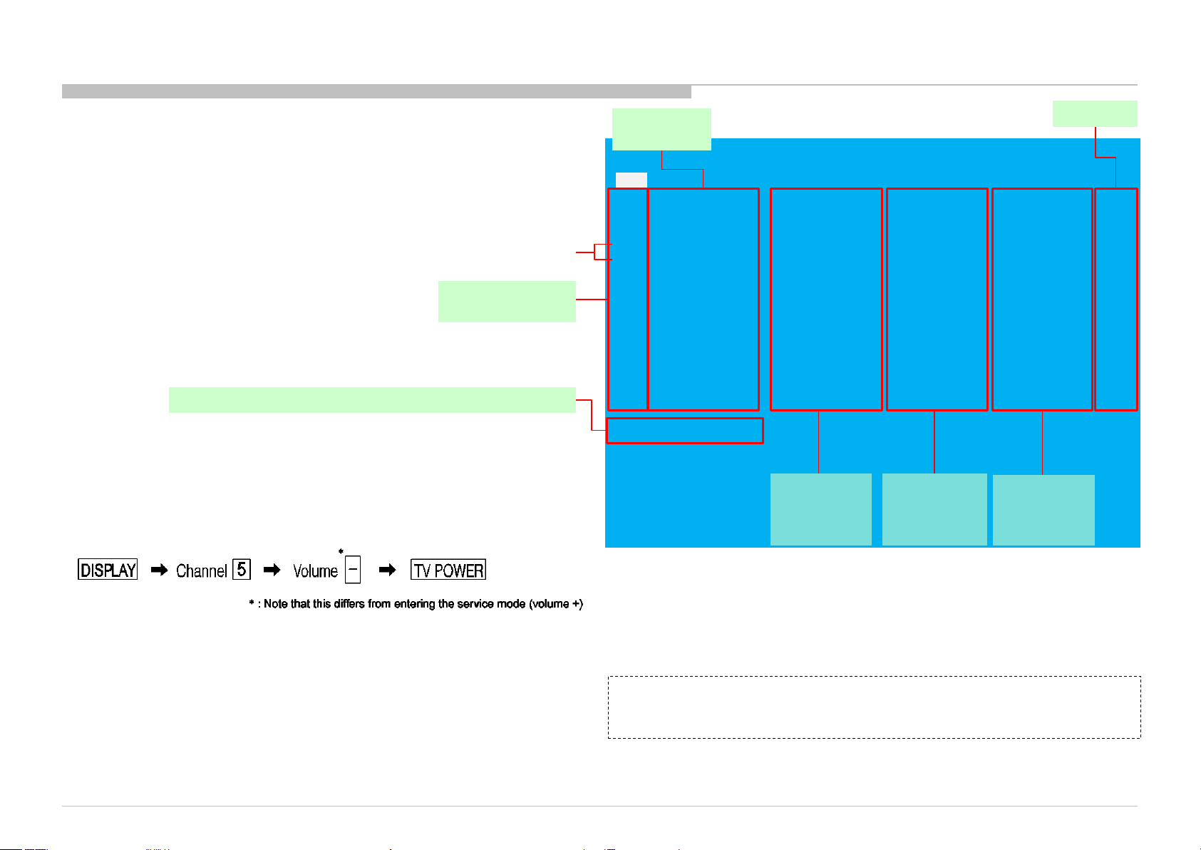
SELF DIAGNOSIS FUNCTION
[SELF DIAGNOSTIC SCREEN DISPLAY] [SELF DIAGNOSTIC SCREEN DISPLAY]
Format of error timestamps
YYMMDDhhmmss (in UTC)
Example:
120823132523 -> Aug 23 2012 13:25:23 UTC
* Only when time is set, an error timestamp
is saved.
• Panel Operation Time is recorded every
30 min, but Total Operation Time is recorded every 1 hr.
Therefore, the panel op. time might become larger than
the total op. time.
Total Operation Time [hr] – Boot Count – Panel Operation Time [hr]
" These error item
does not work."
Smart Core Red
LED blinking count
For errors with symptoms such as “power sometimes shuts off” or “screen sometimes goes
out” that cannot be confirmed, it is possible to bring up past occurrences of failure for
confirmation on the screen.
In standby mode, press buttons on the remote commander sequentially in rapid succession
as shown below:
Error item
Naming
SELF CHECK
Back
<<
002 MAIN_POWER 000000000000 000000000000 000000000000 000
003 DC_ALERT 000000000000 000000000000 000000000000 000
003 AUD_ERR 150101000018 150101000018 150101000018 003
003 HDMI_EQ 150101000123 150101000045 150101000045 003
003 TU_DEMOD 150101000218 150101000223 150101000105 003
004 LD_ERR 000000000000 000000000000 000000000000 000
004 BCM_ERR 000000000000 000000000000 000000000000 000
005 TCON_ERR 150101000504 000000000000 000000000000 001
005 P_ID_ERR 000000000000 000000000000 000000000000 000
006 BACKLIGHT ERR 000000000000 000000000000 000000000000 000
007 TEMP_ERR 150101000200 150101000002 000000000000 002
007 4KBE_ERR 000000000000 000000000000 000000000000 000
008 SW_ERR 000000000000 000000000000 000000000000 000
00005 00414 00002
[Home]Exit
Error
timestamp for
last recorded
error
Error
timestamp for
second last
recorded error
Error
timestamp for
3rd last
recorded error
Error count
Since the diagnostic results displayed on the screen are not automatically cleared, always check the self-diagnostic screen.
After you have completed the repairs, clear the result display to “0”.
Clearing the Self Check Diagnostic List
Panel operation time : Press the Channel 7 => Channel 0 .
To exit the Self Diagnostic screen...
NOTE:
This model does not have the function to clear the error history of self-diagnostic screen
by remote such as press the Channel 8 => Channel 0.
If you want to finish service mode app, do AC OFF/ON
→*Service mode app is disable perfectly if you want to move home menu, push <HOME>button
→*Service mode app do background(not disable perfectly)
KD-55/65S8500C(CH)
9
Page 10
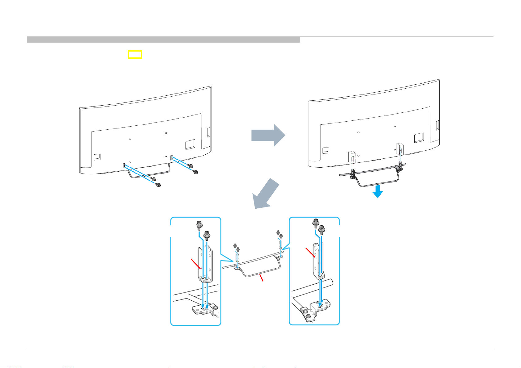
SEC 1. DISASSEMBLY
• There are clutch in the yellow frame[ ]. Therefore please be careful in the case of the disassembly or assembly of parts.
1-1. KD-55S8500C
1-1-1. STAND AND NECK
4 screws (SCREW, +PSW M6X12) P/N: 4-567-081-01
KD-55/65S8500C(CH)
2 screws (SCREW, +PSW M5X20)
NECK
These screws are included in BAG, SCREW A (EGL). P/N: 4-562-758-01
2 screws (SCREW, +PSW M5X20)
NECK
STAND, SHAFT
(2L SLW) A
10
Page 11

1-1. KD-55S8500C
1-1-2. LABEL, REAR TERMINAL AND LABEL, SIDE TERMINAL(W)(CRN)
DISASSEMBLY
KD-55/65S8500C(CH)
LABEL, REAR TERMINAL
LABEL, SIDE TERMINAL(W)(CRN)
11
Page 12

1-1. KD-55S8500C
1-1-3. AC COVER AND POWER SUPPLY CORD
DISASSEMBLY
1
Screw (SCREW, +PSW M3X6 W12) P/N: 4-256-393-01
2
KD-55/65S8500C(CH)
3 4 5
AC COVER
POWER-SUPPLY CORD
12
Page 13

1-1. KD-55S8500C
1-1-4. REAR COVER (L SLW) A
DISASSEMBLY
NOTE:
1
2
REAR COVER (L SLW) A
4 screws (SCREW, +BVTP 4X12 TYPE2 IT-3) P/N: 2-580-639-01
4 screws (SCREW, ORNAMENTAL M6X12) P/N: 4-268-126-02
15 screws (SCREW, +PSW M3X6 W12) P/N: 4-256-393-01
KD-55/65S8500C(CH)
13
Page 14
1-1. KD-55S8500C
1-1-5. TAPE
DISASSEMBLY
TAPE
KD-55/65S8500C(CH)
TAPE
14
Page 15
1-1. KD-55S8500C
1-1-6. TAPE
DISASSEMBLY
KD-55/65S8500C(CH)
TAPE
TAPE TAPE
15
Page 16

1-1. KD-55S8500C
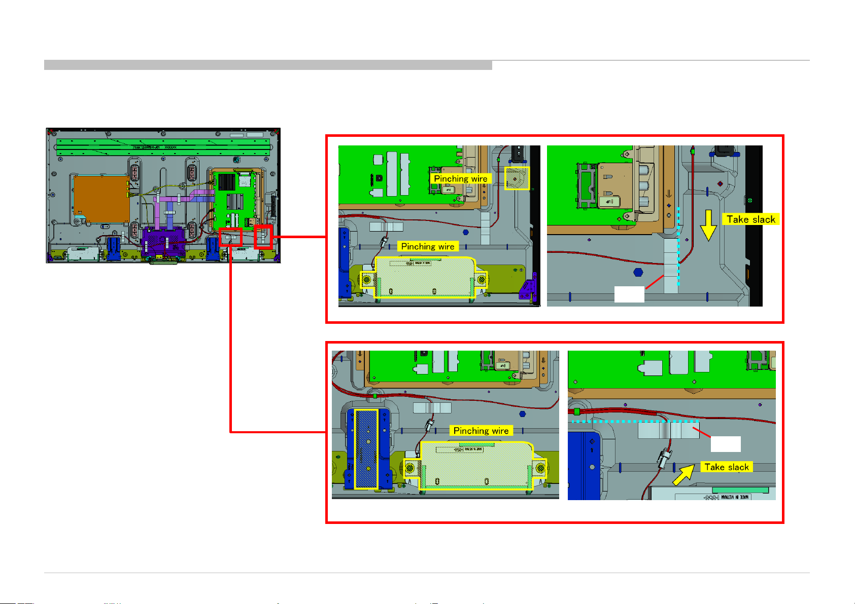
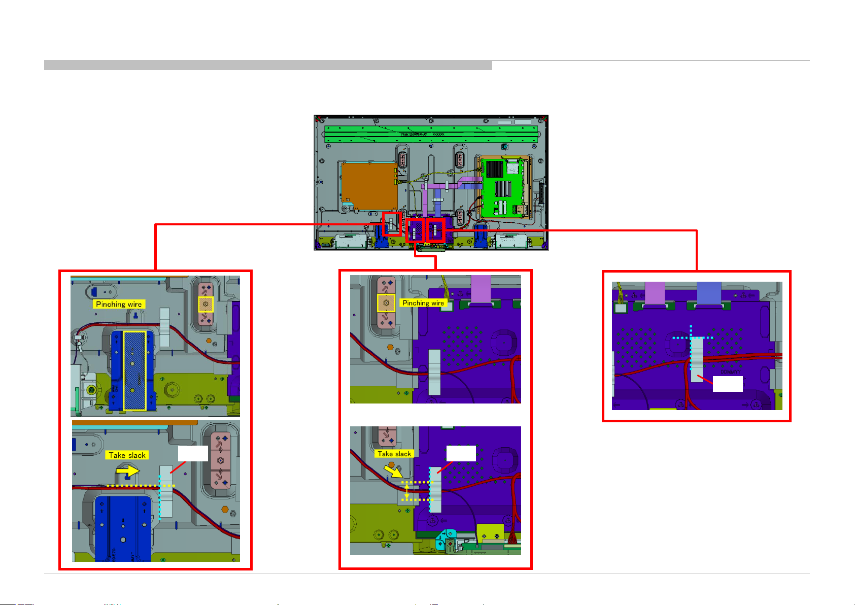
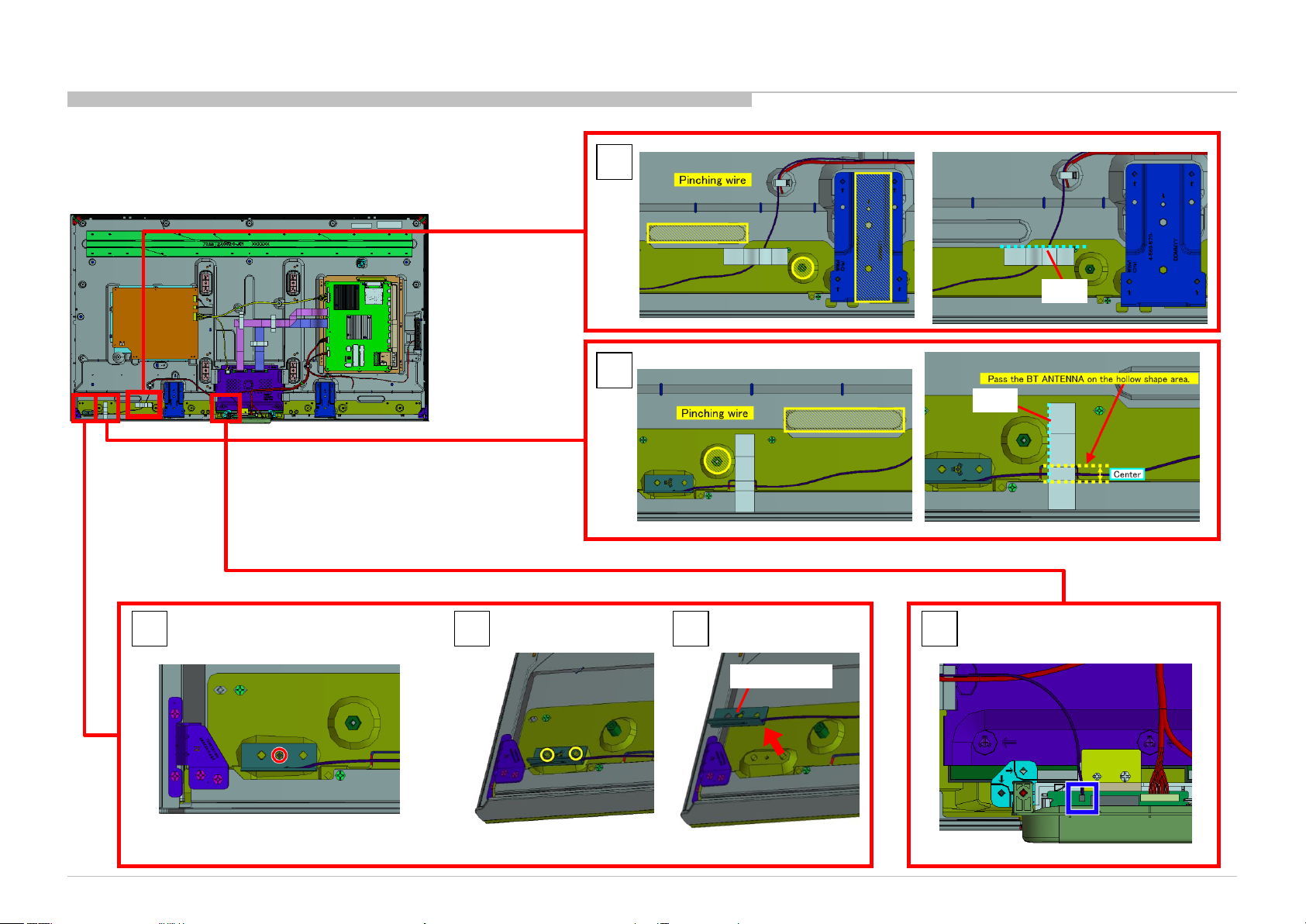
1-1-7. WIRE DRESSING
DISASSEMBLY
KD-55/65S8500C(CH)
16
Page 17

1-1. KD-55S8500C
1-1-8. SPEAKER BOX ASSY (L) AND SPEAKER BOX ASSY (R)
DISASSEMBLY
1
2
3
1
2
3
SPEAKER BOX ASSY (R) SPEAKER BOX ASSY (L)
KD-55/65S8500C(CH)
17
Page 18
1-1. KD-55S8500C
1-1-9. TAPE AND BT ANTENNA
DISASSEMBLY
1
TAPE
2
TAPE
3
Screw (SCREW (+PSW) (M3X6)) P/N: 2-990-421-41
KD-55/65S8500C(CH)
6 4 5
BT ANTENNA
18
Page 19
1-1. KD-55S8500C
1-1-10. SMART CORE
DISASSEMBLY
NOTE:
1 2
SMART CORE
KD-55/65S8500C(CH)
19
Page 20

1-1. KD-55S8500C
1-1-11. SWITCH UNIT (VM-WW)
DISASSEMBLY
1 2
3
SWITCH UNIT
(VM-WW)
KD-55/65S8500C(CH)
4
NOTE:
20
Page 21

1-1. KD-55S8500C
1-1-12. CUSHION (SLW KEY)
DISASSEMBLY
KD-55/65S8500C(CH)
P/N: 4-573-837-01
21
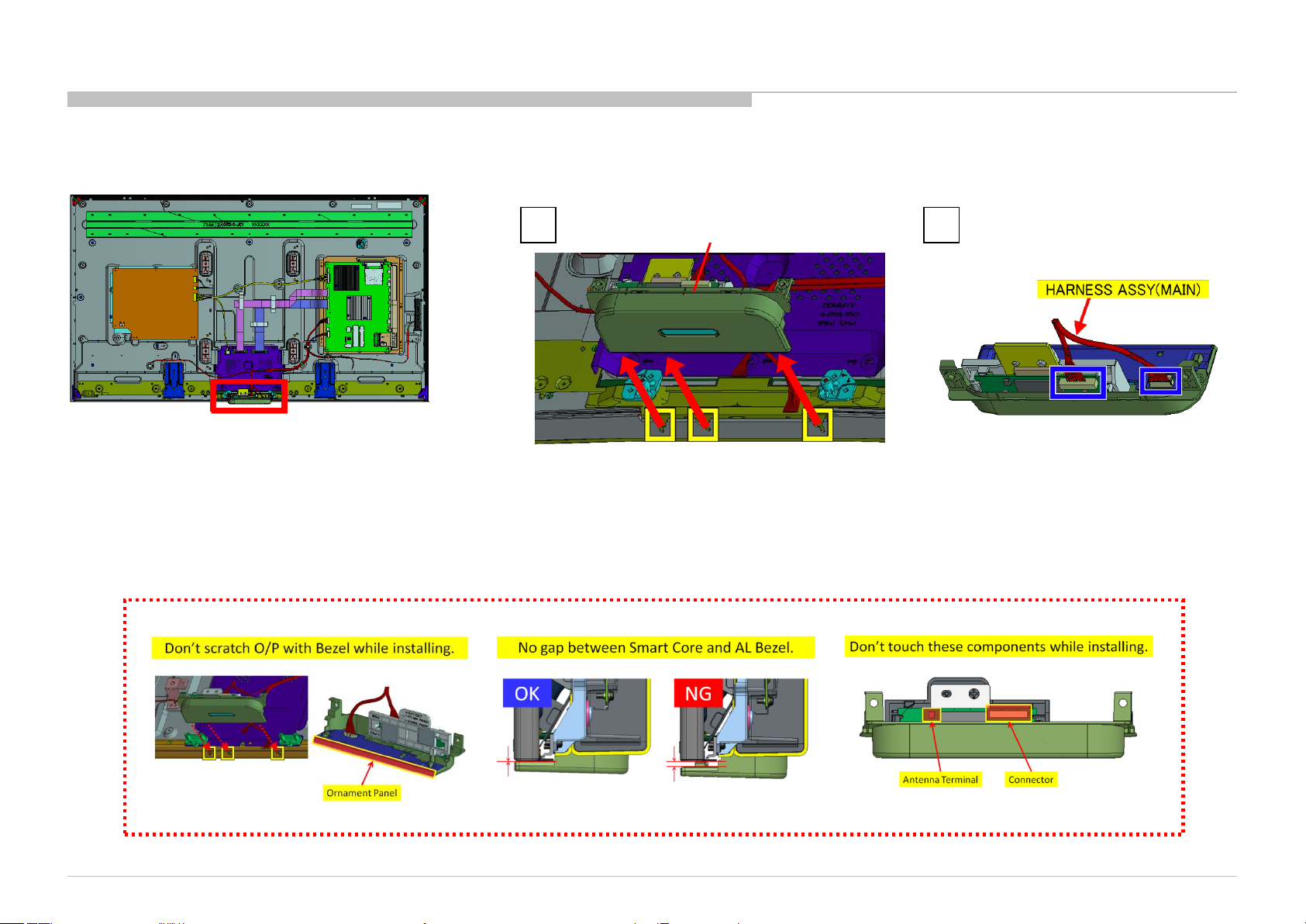
Page 22
1-1. KD-55S8500C
1-1-13. HARNESS ASSY(MAIN) AND CONNECTOR ASSY 28P
DISASSEMBLY
1
2 3
HARNESS ASSY (MAIN)
P/N: 1-910-110-61
CONNECTOR ASSY 28P
P/N: 1-910-110-60
KD-55/65S8500C(CH)
22
Page 23
1-1. KD-55S8500C
1-1-14. TAPE AND BRACKET, SP (LAK)
DISASSEMBLY
NOTE:
When you replace a panel, please cut
TAPE (1350FB-1) 30MMX66M BLK
(P/N:7-600-036-11) to 30x30MM, and
stick it like an illustration.
1
2
KD-55/65S8500C(CH)
2 screws (SCREW (+PSW) (M3X6)) P/N: 2-990-421-41
3
BRACKET, SP (LAK)
23
Page 24
1-1. KD-55S8500C
1-1-15. BRACKET, STD (2L SLW)
DISASSEMBLY
1
2 screws (PULLEY, STAND (HWI)) P/N: 4-534-964-01
2 3 4
8 screws (SCREW, +PSW M4X8) P/N: 2-580-600-11
KD-55/65S8500C(CH)
BRACKET, STD (2L SLW)
24
Page 25

1-1. KD-55S8500C
1-1-16. GL3
DISASSEMBLY
1
6 screws (SCREW, +PSW M3X6 W12) P/N: 4-256-393-11
2 3
KD-55/65S8500C(CH)
GL3
25
Page 26
1-1. KD-55S8500C
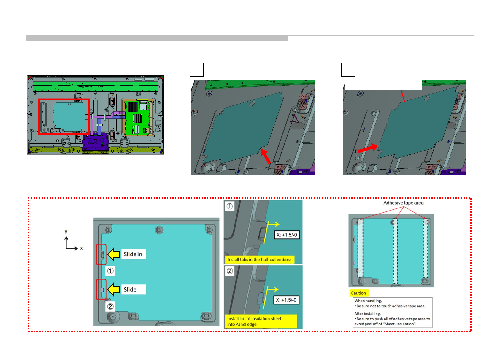
1-1-17. SHEET, INSULATION(HRN L)
NOTE:
DISASSEMBLY
1 2
SHEET, INSULATION(HRN L)
KD-55/65S8500C(CH)
26
Page 27

1-1. KD-55S8500C
1-1-18. BRACKET,VESA(HWK)
DISASSEMBLY
1
8 screws (SCREW, +PSW M4X8) P/N: 2-580-600-11
2 3
KD-55/65S8500C(CH)
BRACKET,VESA(HWK)
27
Page 28
1-1. KD-55S8500C
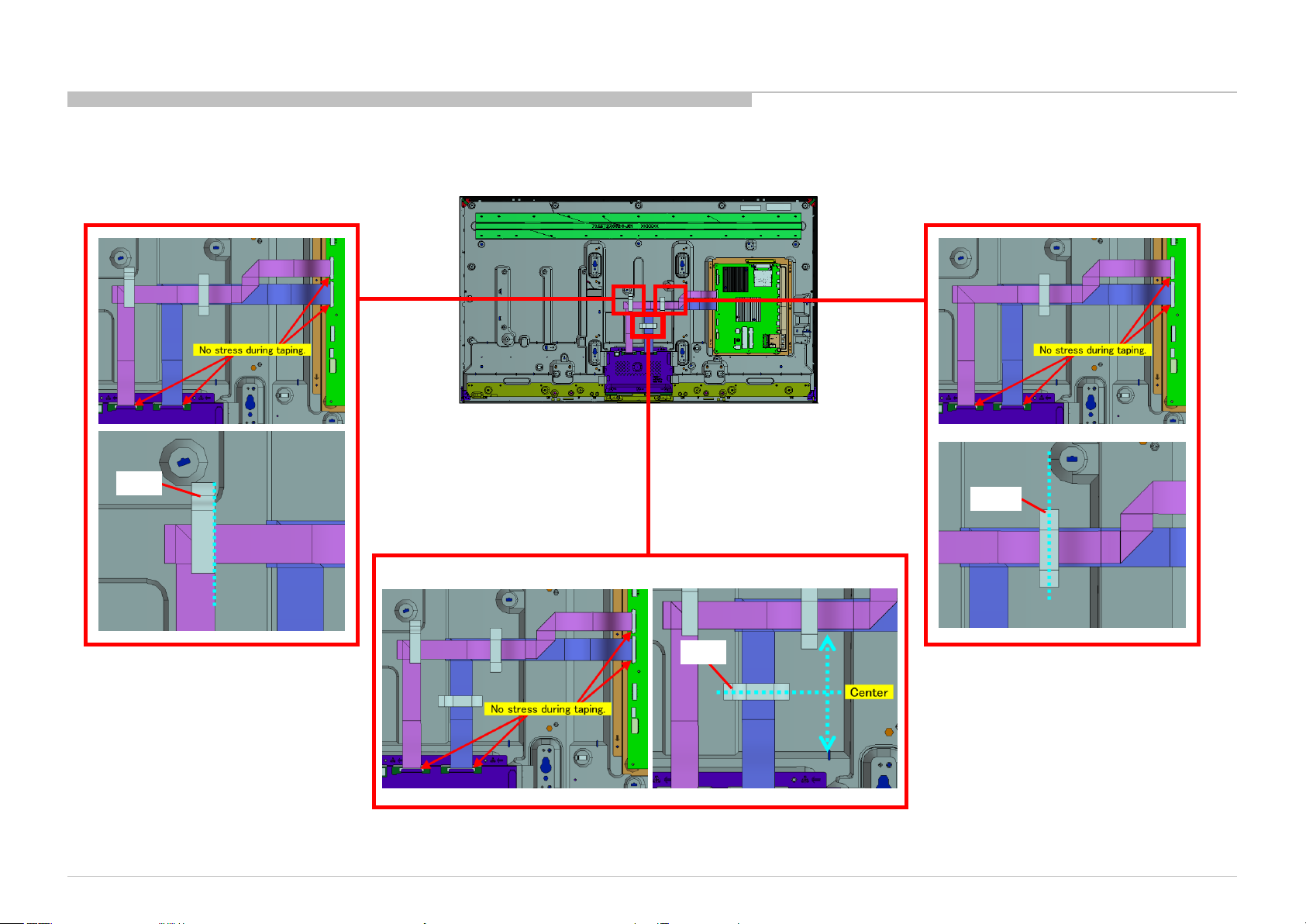
1-1-19. TAPE
TAPE
DISASSEMBLY
TAPE
KD-55/65S8500C(CH)
TAPE
28
Page 29

1-1. KD-55S8500C
1-1-20. FLEXIBLE FLAT CABLE 41P (XCS) AND FLEXIBLE FLAT CABLE 51P (XCS)
1
DISASSEMBLY
FLEXIBLE FLAT CABLE 41P (XCS)
P/N: 1-849-071-11
OK and NG Conditions for FFC insertion
Insert FFC in straight
direction/condition into the connector
and plunge in to the depths.
KD-55/65S8500C(CH)
DO NOT slant the FFC during insertion.
2
FLEXIBLE FLAT CABLE 51P (XCS)
P/N: 1-849-073-11
29
Page 30

1-1. KD-55S8500C
1-1-21. BRACKET, SIDE F (MOLD)
DISASSEMBLY
1
KD-55/65S8500C(CH)
3 2
BRACKET, SIDE F (MOLD)
30
Page 31

1-1. KD-55S8500C
1-1-22. PLATE, MAIN(ALB L) ASSY
DISASSEMBLY
1
6 screws (SCREW, +PSW M3X8) P/N: 2-580-593-01
KD-55/65S8500C(CH)
3 2
PLATE, MAIN(ALB L) ASSY
31
Page 32

1-1. KD-55S8500C
1-1-23. BMFW
DISASSEMBLY
1
8 screws (SCREW (+PSW) (M3X6)) P/N: 2-990-421-41
KD-55/65S8500C(CH)
3 2
BMFW
32
Page 33

1-1. KD-55S8500C
DISASSEMBLY
1-1-24. GASKET (BMF)
Five attachment positions of Gasket BMFW B-Side view
PWB P/N indication location
KD-55/65S8500C(CH)
NOTE:
When you replace a BMFW board, it is necessary to stick five new GASKET on a new BMFW board.
GASKET (BMF): 4-566-117-01
However, please confirm PWB P/N before that.
If the PWB P/N is old type(1-894-595-11/21), need gaskets.
If the PWB P/N is new type(suffix -12/22 or later), no need gaskets.
*There is no problem even if you were mounting a gasket on new type(suffix -12/22 or later).
33
Page 34

1-1. KD-55S8500C
1-1-25. SHEET, THERMAL(BM) AND PLATE, MAIN(ALB L)
1
DISASSEMBLY
SHEET, THERMAL(BM)
KD-55/65S8500C(CH)
2
PLATE, MAIN(ALB L)
34
Page 35

1-1. KD-55S8500C
1-1-26. SLIDE, CLAMP
DISASSEMBLY
1
1
2
SLIDE, CLAMP
2
SLIDE, CLAMP
KD-55/65S8500C(CH)
35
Page 36

1-1. KD-55S8500C
1-1-27. LCD PANEL
DISASSEMBLY
LCD PANEL
KD-55/65S8500C(CH)
36
Page 37

1-2. KD-65S8500C
1-2-1. STAND AND NECK
4 screws (SCREW, +PSW M6X12) P/N: 4-567-081-01
DISASSEMBLY
KD-55/65S8500C(CH)
2 screws (SCREW, +PSW M5X20)
NECK
These screws are included in BAG, SCREW A (EGL). P/N: 4-562-758-01
2 screws (SCREW, +PSW M5X20)
NECK
STAND, SHAFT
(2L SLW) A
37
Page 38

1-2. KD-65S8500C
1-2-2. LABEL, REAR TERMINAL AND LABEL, SIDE TERMINAL(W)(CRN)
DISASSEMBLY
KD-55/65S8500C(CH)
LABEL, REAR TERMINAL
LABEL, SIDE TERMINAL(W)(CRN)
38
Page 39

1-2. KD-65S8500C
1-2-3. AC COVER AND POWER SUPPLY CORD
DISASSEMBLY
1
Screw (SCREW, +PSW M3X6 W12) P/N: 4-256-393-01
2 3 4 5
AC COVER
POWER-SUPPLY CORD
KD-55/65S8500C(CH)
39
Page 40

1-2. KD-65S8500C
1-2-4. REAR COVER (2L SLW) A
DISASSEMBLY
NOTE:
1
4 screws (SCREW, +BVTP 4X12 TYPE2 IT-3) P/N: 2-580-639-01
4 screws (SCREW, ORNAMENTAL M6X12) P/N: 4-268-126-02
18 screws (SCREW, +PSW M3X6 W12) P/N: 4-256-393-01
2
REAR COVER (2L SLW) A
KD-55/65S8500C(CH)
40
Page 41

1-2. KD-65S8500C
1-2-5. TAPE
DISASSEMBLY
KD-55/65S8500C(CH)
TAPE
TAPE
TAPE
TAPE
41
Page 42

1-2. KD-65S8500C
1-2-6. TAPE
DISASSEMBLY
KD-55/65S8500C(CH)
TAPE
TAPE
TAPE
42
Page 43

1-2. KD-65S8500C
1-2-7. WIRE DRESSING
DISASSEMBLY
KD-55/65S8500C(CH)
43
Page 44

1-2. KD-65S8500C
1-2-8. SPEAKER BOX ASSY (L) AND SPEAKER BOX ASSY (R)
DISASSEMBLY
1
2
3
1
2
3
SPEAKER BOX ASSY (R) SPEAKER BOX ASSY (L)
KD-55/65S8500C(CH)
44
Page 45

1-2. KD-65S8500C
1-2-9. BT ANTENNA
DISASSEMBLY
1
2
Screw (SCREW (+PSW) (M3X6)) P/N: 2-990-421-41
KD-55/65S8500C(CH)
3 4
BT ANTENNA
45
Page 46

1-2. KD-65S8500C
1-2-10. SMART CORE
DISASSEMBLY
1 2
SMART CORE
NOTE:
KD-55/65S8500C(CH)
46
Page 47

1-2. KD-65S8500C
1-2-11. SWITCH UNIT (VM-WW)
DISASSEMBLY
1 2
3
SWITCH UNIT
(VM-WW)
KD-55/65S8500C(CH)
4
NOTE:
47
Page 48

1-2. KD-65S8500C
1-2-12. CUSHION (SLW KEY)
DISASSEMBLY
KD-55/65S8500C(CH)
P/N: 4-573-837-01
48
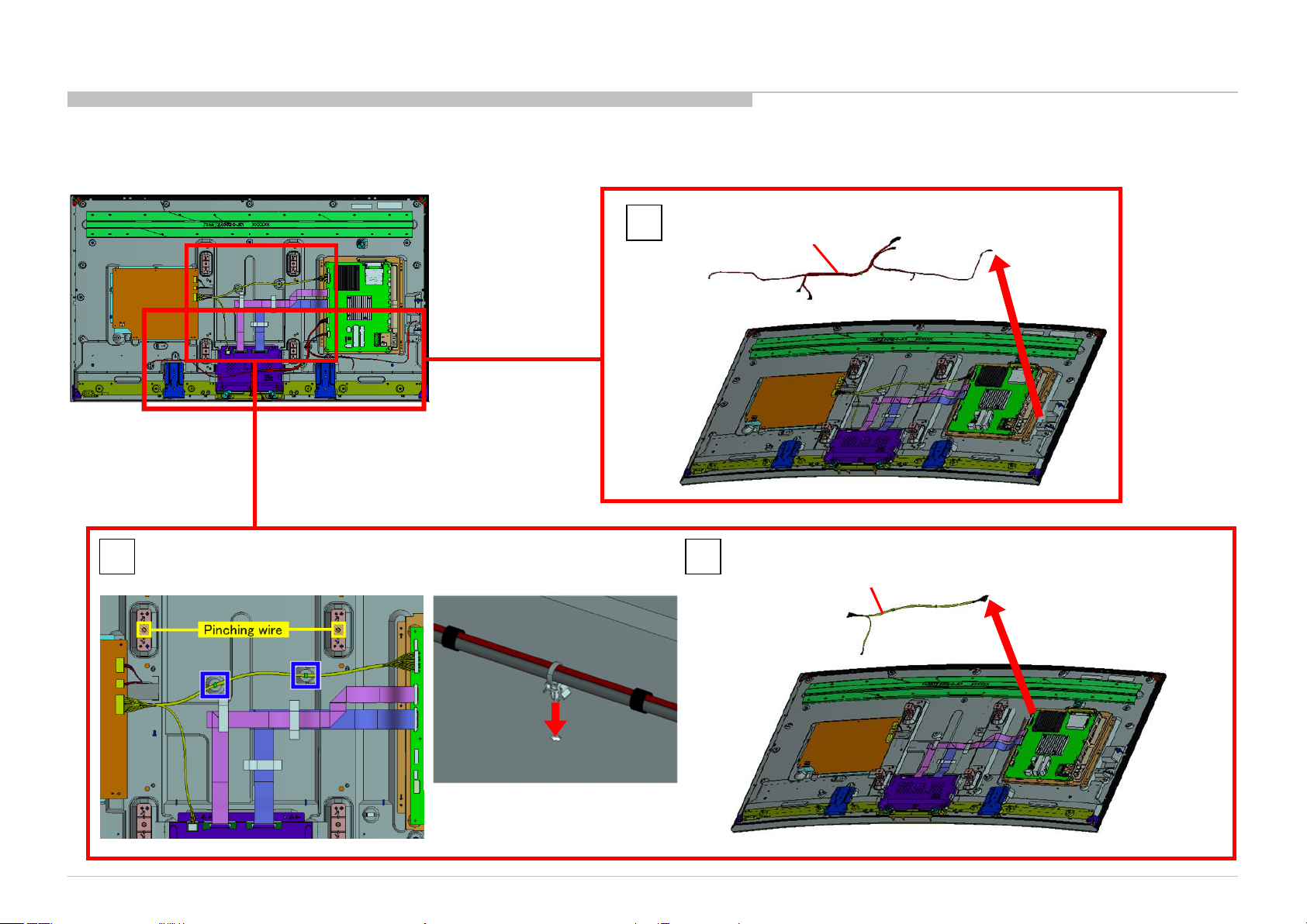
Page 49

1-2. KD-65S8500C
1-2-13. HARNESS ASSY(MAIN) AND HARNESS ASSY AND WIRE DRESSING
DISASSEMBLY
1
HARNESS ASSY(MAIN)
P/N: 1-910-110-63
2 3
HARNESS ASSY
P/N: 1-910-110-62
KD-55/65S8500C(CH)
49
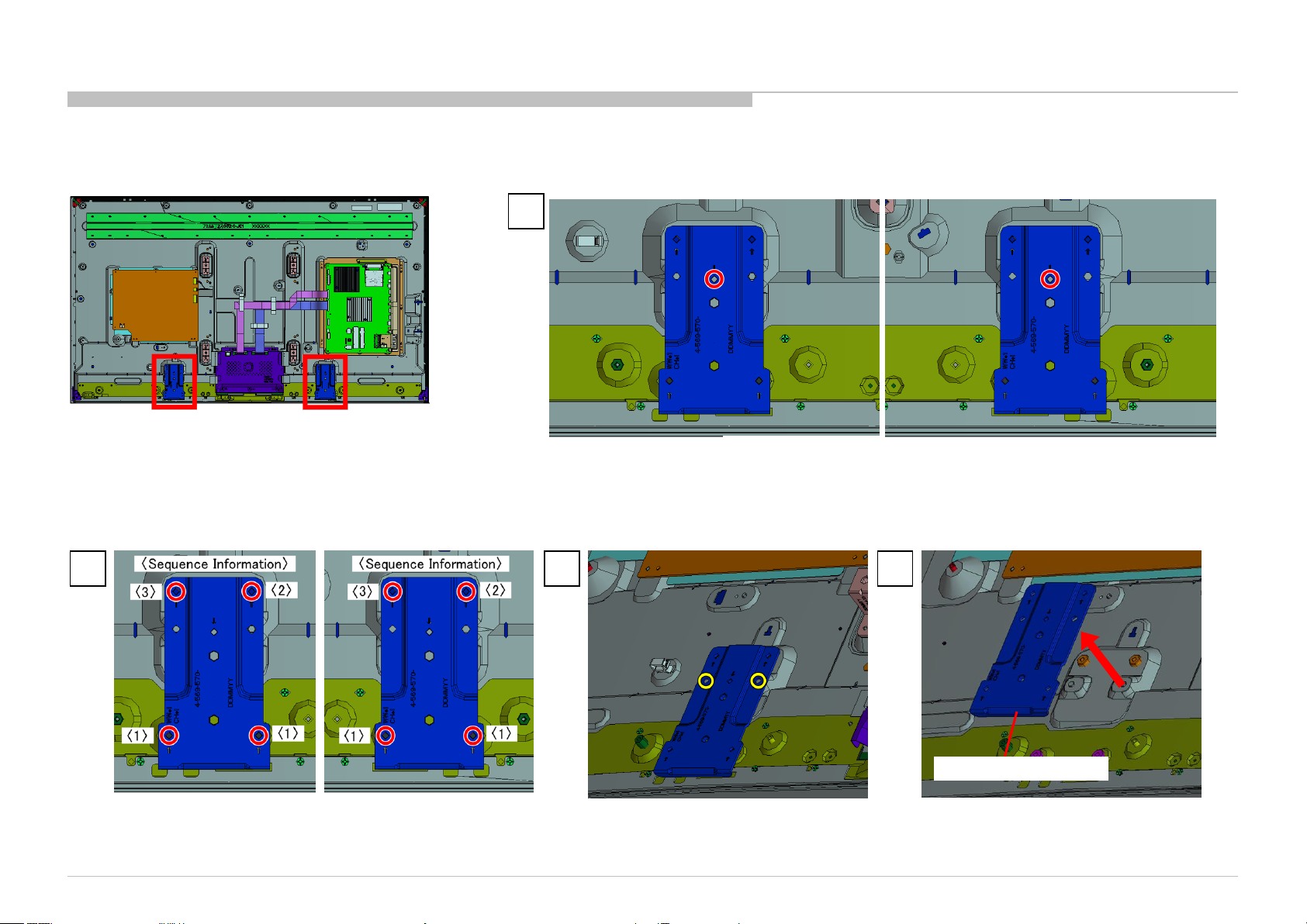
Page 50

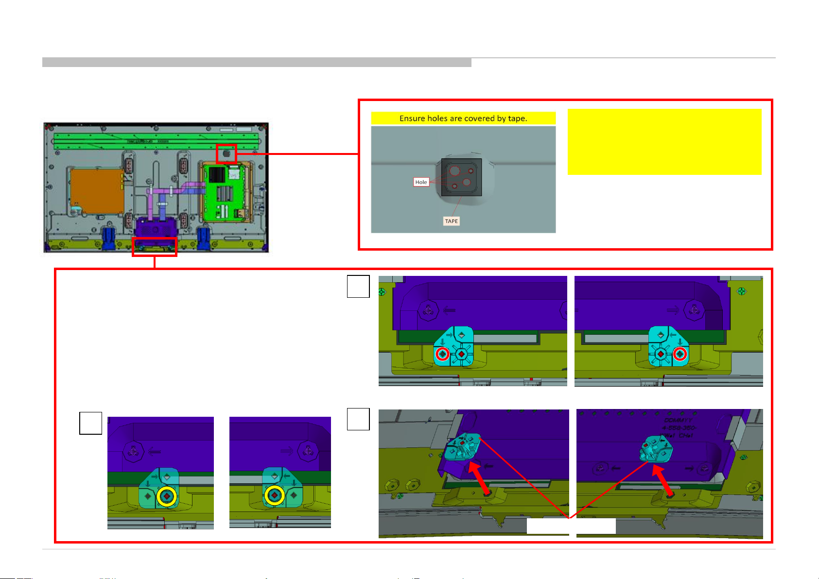
1-2. KD-65S8500C
1-2-14. TAPE AND BRACKET, SP (LAK)
DISASSEMBLY
NOTE:
When you replace a panel, please cut
TAPE (1350FB-1) 30MMX66M BLK
(P/N:7-600-036-11) to 30x30MM, and
stick it like an illustration.
1
2
KD-55/65S8500C(CH)
2 screws (SCREW (+PSW) (M3X6)) P/N: 2-990-421-41
3
BRACKET, SP (LAK)
50
Page 51

1-2. KD-65S8500C
1-2-15. BRACKET, STD (2L SLW)
DISASSEMBLY
1
2 screws (PULLEY, STAND (HWI)) P/N: 4-534-964-01
2 3 4
8 screws (SCREW, +PSW M4X8) P/N: 2-580-600-11
KD-55/65S8500C(CH)
BRACKET, STD (2L SLW)
51
Page 52

1-2. KD-65S8500C
1-2-16. G8
DISASSEMBLY
1
6 screws (SCREW, +PSW M3X6 W12) P/N: 4-256-393-11
2 3
KD-55/65S8500C(CH)
G8
52
Page 53

1-2. KD-65S8500C
1-2-17. SHEET, INSULATION(HWK 2L)
NOTE:
DISASSEMBLY
1 2
SHEET, INSULATION(HWK 2L)
KD-55/65S8500C(CH)
53
Page 54

1-2. KD-65S8500C
1-2-18. FLEXIBLE FLAT CABLE 24P AND BRACKET,VESA(HWK)
DISASSEMBLY
FLEXIBLE FLAT CABLE 24P
P/N: 1-910-110-64
1
8 screws (SCREW, +PSW M4X8) P/N: 2-580-600-11
KD-55/65S8500C(CH)
2
3
BRACKET,VESA(HWK)
54
Page 55

1-2. KD-65S8500C
1-2-19. TAPE
DISASSEMBLY
KD-55/65S8500C(CH)
TAPE
55
Page 56

1-2. KD-65S8500C
1-2-20. FLEXIBLE FLAT CABLE 41P (XCM) AND FLEXIBLE FLAT CABLE 51P (XCM)
DISASSEMBLY
OK and NG Conditions for FFC insertion
Insert FFC in straight
direction/condition into the connector
and plunge in to the depths.
DO NOT slant the FFC during insertion.
1
2
FLEXIBLE FLAT CABLE 41P (XCM)
P/N: 1-849-072-11
FLEXIBLE FLAT CABLE 51P (XCM)
P/N: 1-849-074-11
KD-55/65S8500C(CH)
56
Page 57

1-2. KD-65S8500C
1-2-21. BRACKET, SIDE F (MOLD)
DISASSEMBLY
1
KD-55/65S8500C(CH)
3 2
BRACKET, SIDE F (MOLD)
57
Page 58

1-2. KD-65S8500C
1-2-22. PLATE, MAIN(ALB L) ASSY
DISASSEMBLY
1
6 screws (SCREW, +PSW M3X8) P/N: 2-580-593-01
KD-55/65S8500C(CH)
3 2
PLATE, MAIN(ALB L) ASSY
58
Page 59

1-2. KD-65S8500C
1-2-23. BMFW
DISASSEMBLY
1
8 screws (SCREW (+PSW) (M3X6)) P/N: 2-990-421-41
KD-55/65S8500C(CH)
3 2
BMFW
59
Page 60

1-2. KD-65S8500C
1-2-24. GASKET (BMF)
DISASSEMBLY
Five attachment positions of Gasket BMFW B-Side view
KD-55/65S8500C(CH)
PWB P/N indication location
NOTE:
When you replace a BMFW board, it is necessary to stick five new GASKET on a new BMFW board.
GASKET (BMF): 4-566-117-01
However, please confirm PWB P/N before that.
If the PWB P/N is old type(1-894-595-11/21), need gaskets.
If the PWB P/N is new type(suffix -12/22 or later), no need gaskets.
*There is no problem even if you were mounting a gasket on new type(suffix -12/22 or later).
60
Page 61

1-2. KD-65S8500C
1-2-25. SHEET, THERMAL(BM) AND PLATE, MAIN(ALB L)
1
DISASSEMBLY
SHEET, THERMAL(BM)
KD-55/65S8500C(CH)
2
PLATE, MAIN(ALB L)
61
Page 62

1-2. KD-65S8500C
1-2-26. SLIDE, CLAMP
DISASSEMBLY
1 2
SLIDE, CLAMP
KD-55/65S8500C(CH)
1
2
SLIDE, CLAMP
62
Page 63

1-2. KD-65S8500C
1-2-27. LCD PANEL
DISASSEMBLY
LCD PANEL
KD-55/65S8500C(CH)
63
Page 64

1-3. SMART CORE (M,L)
1-3-1. BRACKET, WIFI ASSY
DISASSEMBLY
1
2
KD-55/65S8500C(CH)
3
BRACKET, WIFI ASSY
64
Page 65

1-3. SMART CORE (M,L)
1-3-2. WLAN / BT MODULE(11AC) ASSY
DISASSEMBLY
3
2
1
2
NOTE:
WLAN / BT MODULE(11AC) ASSY
KD-55/65S8500C(CH)
1
65
Page 66

1-3. SMART CORE (M,L)
1-3-3. SHEET, THERMAL (SC) AND WLAN/BT MODULE(11AC)
SHEET, THERMAL (SC)
Opposite side of WLAN / BT MODULE (11AC) ASSY
DISASSEMBLY
WLAN / BT MODULE(11AC)
1-3-4. HEAT SINK L (SC) AND BRACKET, WIFI
KD-55/65S8500C(CH)
1 2
HEAT SINK L (SC)
BRACKET, WIFI
66
Page 67

1-3. SMART CORE (M,L)
1-3-5. COVER, TOP
DISASSEMBLY
1
KD-55/65S8500C(CH)
2
COVER, TOP
67
Page 68

1-3. SMART CORE (M,L)
1-3-6. PANEL, ORNAMENT
DISASSEMBLY
1
KD-55/65S8500C(CH)
2 3
PANEL, ORNAMENT
68
Page 69

1-3. SMART CORE (M,L)
1-3-7. LIGHT, GUIDE
DISASSEMBLY
1
KD-55/65S8500C(CH)
2 3
LIGHT, GUIDE
Lock Portion
69
Page 70

1-3. SMART CORE (M,L)
1-3-8. HSC3_S_M MOUNT
DISASSEMBLY
3
1
2
HSC3_S_M MOUNT
KD-55/65S8500C(CH)
70
Page 71

1-3. SMART CORE (M,L)
1-3-9. CASE, BOTTOM (M)
DISASSEMBLY
KD-55/65S8500C(CH)
CASE, BOTTOM (M)
71
Page 72

SEC 2. ADJUSTMENT
HOW TO ENTERING SERVICE MODE
1) Turn on the main power switch to place the set in standby mode.
2) Press the buttons on the remote commander as follows, and entering service mode.
3) Service mode display.
Service Mode
Model Information
Self diagnosis History
Video / Audio
Panel / PQ
General Setting
Tuner
Wifi
>>
>>
>>
>>
>>
>>
>>
[</>] Set [Home]Exit
4) How to use the remote commander.
Function The flow of control
Service mode on <Display><5><Vol Up><Power>
Service mode off <MENU>/<HOME>
Item up / down
Item select left/right <←>/<→>
Execute <OK>
5) When finished the operation of service mode , please AC Plug OFF/ON the TV set.
(*If you don’t do AC plug OFF/ON, remain the Service Mode App and User can see the Service Mode after RC ON.)
KD-55/65S8500C(CH)
<↑>/ <↓>
72
Page 73

SOFTWARE VERSION
>>
Model Information
>>
Model Number Setting
>>
SERIAL NUMBER EDIT
[</>] Set [Home]Exit
Model
Status Information
1) In Service Mode, select “Model Information”, press “Enter” or “→” button to enter Status Information.
ADJUSTMENT
Model Information
Self diagnosis History
Video / Audio
Panel / PQ
General Setting
Tuner
Wifi
Service Mode
>>
>>
>>
>>
>>
>>
>>
[</>] Set [Home]Exit
2) Press “Enter” or “Return” button to return to Service Mode.
Service Mode
Model Information
Self diagnosis History
Video / Audio
Panel / PQ
General Setting
Tuner
Wifi
>>
>>
>>
>>
>>
>>
>>
>>
Main Micro
SW Version:
NVM Version:
Boot Version:
PQ Version:
AQ Version:
<Ext>
exFRC:
CameraVID:
CameraPIC:
CameraFW:
4k BE
MLFW:
MAFW:
ADSP
NDAT
PDAT
BDAT
BCM
FDAT
UDAT
BDIX
PKG2.011.0010NAB
0001 UC2
V1.000
102100006
AQ1.100
00.00.00.00
0
0
0
SF1.002
SF0.360
SF0.501
SD0.370
SD0.370
SD1.011
SD------SD0.002
SD0.000
SD0.370
KD-55/65S8500C(CH)
[</>] Set [Home]Exit
73
Page 74

SERIAL NUMBER EDIT (1)
ADJUSTMENT
1) In “Service Mode”, select “Model Information” by pressing “↑” or “↓” then pressing “Enter” or
“→” button to enter inside.
2) Select “Serial Number Edit” by pressing “↑” or “↓” button then pressing “Enter” or “→” button
3) Press “↑” or “↓” to input numbers.
4) After user input data , press <Enter> .
• Pop-up dialog appear to confirm input data correct
• Serial Number can be set ONLY ONCE
5) Press “→” or “←” button to select YES or NO.
Select YES if input data is correct.
Select NO if input data is incorrect.
Press <Enter> to save answer.
Model Information
Self diagnosis History
Video / Audio
Panel / PQ
General Setting
Tuner
Wifi
Status Information
Model Information
Model Number Setting
Serial Number Edit
Status Information
Model Information
Model Number Setting
Serial Number Edit
Service Mode
>>
>>
>>
>>
>>
>>
>>
[</>] Set [Home]Exit
Mode
Service Mode
>>
>>
>>
_ _ _ _ _ _ _
>>
>>
>>
9 9 9 9 9 9 9
KD-55/65S8500C(CH)
Input Data correct?
Yes No
74
Page 75

SERIAL NUMBER EDIT (2)
Yes No
Input Data correct?
ADJUSTMENT
If YES is selected, the input data is saved into EEPROM.
SERIAL NUMBER EDIT is greyed out and the serial number that has been input is displayed.
User will not able to edit anymore.
If NO is selected, the input data is not saved into EEPROM.
The serial number that has been input is displayed.
User can still edit the Serial Number.
Status Information
Model Information
Model Number Setting
Serial Number Edit
Status Information
Model Information
Model Number Setting
Serial Number Edit
Service Mode
<[ ]>
Service Mode
<[ ]>
>>
>>
KDL-40X500B
9 9 9 9 9 9 9
>>
>>
KDL-40X500B
9 9 9 9 9 9 9
KD-55/65S8500C(CH)
75
Page 76

MODEL NUMBER SETTING
_ _ _ _ _ _ _ _ _ _ _ _
OK
[MODEL_NUMBER_SETTING]
1) In “Service Mode”, select “Model Information” by pressing “↑” or “↓” then pressing “Enter” or “→” button to enter inside.
2) Select “Model Number Setting” by pressing “↑” or “↓” button then pressing “Enter” or “→” button.
3) Press “↑” or “↓” arrow key to scroll Product Name Candidate.
(e.g. KDL-40X500B CO1,KDL-40X500C BR6)
ADJUSTMENT
Service Mode
Model Information
Self diagnosis History
Video / Audio
Panel / PQ
General Setting
Tuner
Wifi
>>
>>
>>
>>
>>
>>
>>
Status Information
Model Information
Model Number Setting
Serial Number Edit
Service Mode
>>
>>
>>
>>
[</>] Set [Home]Exit
4) Select one Product Name from the list, press <Enter> will pop dialog to inform user to confirm data. Model dependent settings will be overwritten into EEPROM.
KD-55/65S8500C(CH)
76
Page 77

ADJUSTMENT
Back
R WB Gain
<[ 0 ]>
G WB Gai n
<[ 0 ]>
B WB Gain
<[ 0 ]>
R WB Offs et
<[ 0 ]>
G WB Offs et
<[ 0 ]>
B WB Offs et
<[ 0 ]>
<<
[</>] Set [Home]Exit
>>
>>
>>
>>
>>
>>
>>
Service Mode
Tuner
Wifi / BT
Model Information
Self diagnosis History
Video / Audio
Panel / PQ
General Setting
WB ADJUSTMENT
(Please apply Main board or panel is replaced.)
In “Panel/PQ” service mode.
a. Go to “WB Adjustment” category by “↑” or “↓”.
b. To select “WB Adjustment”, press “→” button.
c. To change data , press “←” or “→” on remote commander.
KD-55/65S8500C(CH)
77
Page 78

ADJUSTMENT
>>
>>
>>
>>
>>
>>
>>
Service Mode
Tuner
Wifi / BT
Model Information
Self diagnosis History
Video / Audio
Panel / PQ
General Setting
Back
<<
<[ 0. SoC to T-con ]>
Mura data transfer
<[ 0. SoC to T-con ]>
CUC data trans fer
<[ 0. SoC to T-con ]>
[Start]
[</>] Set [Home]Exit
WB/Gamma data trans fer
WB/MURA/CUC DATA TRANSFER
(Please apply Main board or panel is replaced.)
1. In “Panel/PQ” service mode.
a. Go to “WB/Mura/CUC data transfer” category by “↑” or “↓”.
b. To select “WB/Mura/CUC data transfer”, press “→” button.
c. To change data , press “←” or “→” on remote commander.
2. In “WB/Mura/CUC data transfer”.
a. Select “WB/Gamma data transfer” by pressing “↑” or “↓” on remote commander.
b. To change the items, press “←” or “→” on remote commander and press “Enter”
button.
Selectable items are:
0. SoC to T-con
1. T-con to SoC
2. Not atction
c. Select “[start]” and press “Enter” button to start transfer.
KD-55/65S8500C(CH)
78
Page 79

SEC 3. TROUBLE SHOOTING
Bluetooth
Power LED
& does not
response to
Stationary
colored
lines or
dots
No video One
No video all
Smart Core no
Bluetooth /
) can't
Wifi & BT Module
(Communi
TEMP
Software
Emitter
Local
UART
3-1. TRIAGE
1. Confirm the claimed symptom.
2. Select that symptom from the chart.
3. Bring all the boards and cables listed for that symptom.
4. Follow the troubleshooting charts in the technical guides to isolate the board.
5. Chart Color Code.
RED DOT: Most likely defective part
BLUE TRIANGLE: Secondary possible defective part
BLACK TEXT: Board that may correct the symptom
Reference
B* Board
G* Board
H* Board
K* Board
Speaker
LD* Board
V By One FFC
Tcon
LCD Panel
Problem
Symptoms - Shutdown. Power LED
blinking red diagnostics sequences
2 3 4 5 6 7 8 9 10
p l p
l p p
p
p
Power Power LD
Audio
Local
I2C
p p l l
p l
l
p
p
l
l l p
Panel
cation)
Panel
(Backlight)
l
p
No
Power
No White
remote
(Dead Set)
p p l l p p l p p p
l
p
p
p
l
Video
- missing or distorted
of Inputs
Inputs
p
p
p
p
Remote Network Audio Skype Smart Core
No Remote
l
Wireless
can't connect
l
No Audio
p
l
l
Skype
Can't Work
p
LED (Set is still
alive)
l
(BT)
One Step
Remote
(OSR
connect
l
KD-55/65S8500C(CH)
79
Page 80

3-2. NO POWER
3-2-1. NO POWER-PCU
No Power
TROUBLE SHOOTING
Check STBY 3.3V
C9030
On B* board
OK
B* Board
NG
Replace
Between G* Board to
B* Board Harness
OK
Harness
u-Com Failure
DDCON/LDO
Main Device Failure
NG
G* Board
KD-55/65S8500C(CH)
80
Page 81

3-2-2. NO POWER-U-Com Failure (1/2)
START
TROUBLE SHOOTING
Check C9117 Voltage.
Is the voltage >3.0V?
Yes
Check R9186 Voltage.
Is the voltage >3.0V?
Yes
Check OPWRSB
R9179 Voltage.
Is the voltage 0V?
Yes
Check POWER_ON
P-on ucom #pin19
Is the voltage >3.0V?
yes
No
No
No
No
Check +3.3V_STBY
R9144, CN9000 #26pin
Check DC_OFF_DET
IC9018
Check STBY_MHL
R9176 Voltage.
Is the voltage >3.0V?
Yes
No problem
TV set stays in
STBY MHL charge mode.
Try AC Off and On after few minutes.
If #pin19 keep Low, change IC9017.
If #pin19 goes High few seconds and downs to Low,
Check G board and harness.
No
SOC
Muffin
problem
Check MAIN_VCC
R9175 Voltage.
Is the voltage >1.6V?
Yes
Check P_ON_VBUS
P-on ucom #pin11
is >3.0V?
Yes
Check P_ON_#1
P-on ucom #pin13
is >3.0V?
Yes
Check PGOOD_1
R9173 Voltage.
Is the voltage >3.0V?
A
No
No
No
No
G-Board
Change IC9017
Change IC9017
No POWER - DDCON/LDO
Check 1.0V DDCON (IC9008)
Check P_ON_LNB
P-on ucom #pin15
Is the voltage >3.0V?
KD-55/65S8500C(CH)
No
Change IC9017
Yes
81
Page 82

3-2-2. NO POWER-U-Com Failure (2/2)
A
Yes
TROUBLE SHOOTING
Check P_ON_#2
P-on ucom #pin14
Is the voltage >3.0V?
Yes
Check ORESETB
P-on ucom #pin12
Is the voltage >3.0V?
Yes
Check X_SYSTEM_RST
P-on ucom #pin16
Is the voltage >3.0V?
Yes
If PANEL_PWER_ON (R9172) is 0V
Check XRST
P-on ucom #pin17
Is the voltage >3.0V?
Yes
If BL_MUTE (R9174) is 0V
Check BL_ON
P-on ucom #pin18
Is the voltage >3.0V?
Yes
No
No
No
No
No
Change IC9017
Change IC9017
Change IC9017
Change IC9017
Change IC9017
Ucom IC9017 is working OK
KD-55/65S8500C(CH)
END
82
Page 83

TROUBLE SHOOTING
3-2-3. NO POWER: DC_OFF_DET check
START
Check Vdd
C9118
Is voltage >5V?
Yes
END
No
Change IC9018
3-2-4. NO POWER: DDCONs check
START
Check fuse
F9xxx
Is fuse OK?
Yes
Check Vcc voltage
C9xxx
Is voltage >12.0V?
Yes
Check Enable pin
voltage
Is voltage >2.5V?
Yes
Change DDCON IC
No
No
No
Check POWER_ON P-on ucom #pin19
(Refer to No Power U-Com Failure)
No Power U-Com Failure
Change Fuse
KD-55/65S8500C(CH)
83
Page 84

3-2-5. NO POWER: DDCON check
START
TROUBLE SHOOTING
Check IC9403 Vcc voltage
C9428
Is voltage >12V?
Yes
Check Vcc voltage
C9061
Is voltage >4V?
Yes
Check Enable
IC9010 #pin1
Is voltage >2.5V?
Yes
Change DDCON
IC9009
No
No
No
Check Vcc voltage
C9061
Is voltage >3V?
Yes
Check
D9001
Is diode ?
Yes
Change IC9010
No
No
Check
D9000
Is diode ?
No
Yes
Change D9001
Check +5V_MAIN DDCON (IC9001)
Change D9000
Check G board and harness
KD-55/65S8500C(CH)
84
Page 85

3-2-6. NO POWER: LDOs check check
START
Yes
TROUBLE SHOOTING
Check Vcc voltage
C9xxx
Is voltage >3V?
Yes
Check Enable pin
voltage
Is voltage >3V?
Yes
Change LDO IC
No
No
Check +3.3V_MAIN DDCON (IC9003)
1.2 No Power U-Com Failure
KD-55/65S8500C(CH)
85
Page 86

3-3. STANDBY LED BLINKING
3-3-1. 2 Times Blinking (Main power Error)
TROUBLE SHOOTING
3-3-2. 3 Times Blinking (DC Alert)
2-time blinking
Check +12V_REG
at pin 13/15/17 of CN9000
on B* Board,
Voltage > 13.2V ?
No
B* Board
Yes
G* Board
BMFL/BMFW board
3-time blinking
Check +5.0V_MAIN
at pin1 in IC8001, 4.959V
<Voltage<5.285V?
OK
AUDIO
Go to Audio check point
NG
DC_ALERT
IC9014,etc
(B* Board)
KD-55/65S8500C(CH)
86
Page 87

3-3-3. 3 Times Blinking (Audio Error)
TROUBLE SHOOTING
LED 3x blinking
Audio Error ?
Yes
Go to page
Power Off Checking*1
Go to page
Power off Checking*2
No
See other flow
Segment “XS”?
No
Yes
Replace B-K Harness
OK ?
No
Replace K-PWB
OK ?
No
Replace B-PWB
OK ?
Yes
Yes
Yes
B-K harness NG
K-PWB NG
B-PWB NG
KD-55/65S8500C(CH)
87
Page 88

1) Power Off Checking*1
Power Off Check*1
Segment “XS”?
Yes
No
(1) B-PWB
PVDD-GND short ?
(See Note 1)
Yes
(1) PVDD-GND short check
Measure impedance between PVDD and GND at C7706,
C7707.
If impedance is <100Ω → NG
(2) LDO out short check
Measure impedance between +3.3V and GND at C9130.
If impedance is <100Ω → NG
(3) Fuse open check
Measure impedance of fuse F7700, F7702 5A (12.5V)
If fuse open → NG
(1) K-PWB
PVDD-GND short ?
(See Note 2)
Yes
TROUBLE SHOOTING
Note 2: Note 1:
(1) PVDD-GND short check
Measure impedance between PVDD and GND at C7722, C7762, C7782,
C7834.
If impedance is <100Ω → NG
(2) LDO out short check
Measure impedance between +3.3V and GND at
C7909.
If impedance is <100Ω → NG
(3) Fuse open check
Measure impedance of fuse
F7702, F7704, F7705, F7701 5A (12.5V)
F7700 3.15A (DDC5V)
If fuse open → NG
Power Off Check*3
(2) B-PWB
LDO out short ?
(See Note 1)
(3) B-PWB
Fuse broken ?
(See Note 1)
KD-55/65S8500C(CH)
No
No
No
Yes
Yes
Replace B-PWB
No
(2) K-PWB
LDO out short ?
(See Note 2)
No
(3) K-PWB
Fuse broken ?
(See Note 2)
No
Yes
Yes
Replace K-PWB
Measure the Speaker
impedance by multi-meter
Less than 3Ω ?
No
Confirm the speaker
harness
Cut or shorted
to the chassis ?
No
Return to LED 3x blinking
or Power Off Checking*3
Yes
Replace Speaker
Replace Speaker Harness
Yes
88
Page 89

2) Power Off Checking*2
Power Off Check*2
Segment “XS”?
No
(4) 12.5V check
12.5V is supplied to
B-PWB for a moment
before LED 3x blinking ?
No
Yes
Yes
(5) 12.5V check
12.5V is supplied to
K-PWB for a moment
before LED 3x blinking ?
No
Yes
TROUBLE SHOOTING
(4) 12.5V check BMFL / BMFW
Measure voltage between PVDD and GND at
capacitor C7706 or C7707.(See 3.3)
Voltage rise more than 0V for a moment at
power on
→ Yes
(5) 12.5V check KS-PWB (XS)
Measure voltage between PVDD and GND at
capacitor C7722, C7762, C7782 or C7834. (See
3.3)
Voltage rise more than 0V for a moment at
power on
→ Yes
Replace B-K Harness
KD-55/65S8500C(CH)
OK ?
No
Replace G-PWB
OK ?
No
Return to
LED 3x blinking
Yes
Yes
Finish
Replace G-K Harness
OK ?
No
Replace G-PWB
OK ?
No
Return to
LED 3x blinking
Yes
Yes
Finish
89
Page 90

3) Power Off Checking*3
No Sound
Without LED 3x
AV receiver is connected
to HDMI in ?
Yes
Select [External Inputs]→
[BRAVIA Sync Settings]→
[BRAVIA Sync Control]→[off]
No sound only
Analog RF and Digital RF ?
No
TROUBLE SHOOTING
Yes
Go to
No Sound Tuner
No
[Speakers] setting is
[Audio System] ?
No
Headphone is connected to
HP/Audio Out terminal ?
No
[Sound]→
[Headphone Speaker Link]
setting is [On] ?
No
Go to
Power Off Checking*1
Yes
Yes
Yes
Change the setting to
[TV Speakers]
Disconnect the Headphone
Change [Sound]→
[Headphone Speaker Link]
Yes
to [Off], OK ?
No
Replace B-PWB
HP/Audio out terminal or Headphone detect
GPIO may be broken
No sound only HDMI ?
No
Go to
No Sound Audio
Yes
Go to
No Sound HDMI
KD-55/65S8500C(CH)
90
Page 91

3-3-4. 4 Times Blinking (LED Voltage Error)
4-time blinking
Between 0.898V to 2.997V
TROUBLE SHOOTING
on the B* Board
0.897V or less
Check
R9027
B* Board
LED driver or G* board
Change LD board or G* board.
KD-55/65S8500C(CH)
91
Page 92

3-3-5. 5 Times Blinking (Panel Communication Error)
5-times blinking
TROUBLE SHOOTING
Check
“+12.5V_TCON” at
CN9000
on the B-Board
OK
Replace the Harness
Between G-Board
and B-Board
NG
Replace
the V-By-One FFC
NG
NG
Replace G-Board
Symptom
improve
Symptom
improve
OK
NG
Harness is
suspicious
V-By-One FFC
is suspicious
G-Board is
suspicious
Change
B-Board
Symptom
improvement
B-Board is
suspicious
NG
Panel (T-con)
Panel (T-Con) is
suspicious
Change
Symptom
improvement
KD-55/65S8500C(CH)
92
Page 93

3-3-6. 6 Times Blinking (Backlight Error)
6-times blinking
TROUBLE SHOOTING
Check a voltage of
BL_ERR_DET.
Check point is
JL9007
or
23pin of CN9000
on B*Board
Voltage < 1.8 V
Voltage ≥ 1.9 V
Check
harness/connection
G*board to B*Board
or
LD board to B*Board
Harness /
Connection OK
Harness /
Connection
broken
Change LD board or G* board.
No improvement
No Improvement
Change
harness
No improvement
LED driver or G* board
Change
Panel
Change
B* board
Symptom
Improvement
Symptom
Improvement
Symptom
Improvement
Symptom
Improvement
Harness
LD board/G board
Panel
B* Board
KD-55/65S8500C(CH)
93
Page 94

3-3-7. 7 Times Blinking (Temperature Error)
7-time blinking
Setting
circumstance is OK?
Temperature,
No
Set to another
location, etc.
Ventilation, etc.
Yes
TROUBLE SHOOTING
Change B* Board,
and Aging a few
hours
Symptom
improvement
B* Board NG
NG
Panel
Check I2C_C bus
communication OK?
(check the next page)
No
I2C_C bus dumping or
Muffin check
Yes
Temp sensor
IC1400
KD-55/65S8500C(CH)
94
Page 95

3-4. NO SOUND
3-4-1. No Sound Audio
TROUBLE SHOOTING
3-4-2. No Sound : TUNER
No Sound
Audio
Segment “XS”?
No
Yes
Replace B-K Harness
OK ?
No
Replace K-PWB
OK ?
No
Yes
Yes
No Sound with normal picture
Only RF tuner input?
YES
Check IC1000 (SOC)
NO
Please refer Audio
troubleshooting
KD-55/65S8500C(CH)
Replace B-PWB
OK ?
Finish
Yes
95
Page 96

3-4-3. No Sound : MHL
No Sound
Check the picture
OK
TROUBLE SHOOTING
NG
Refer to MHL NO PICTURE
Check Sound by other TV set
which is same model
NG
Check Source equipment
by Reference TV set
(For example, Samsung TV(UN46ES7000),
Toshiba TV(42WL863), RB1 or RB2)
NG
Check the settings of
Source equipment
OK
Refer to No Sound Audio
OK
Change B-Board.
KD-55/65S8500C(CH)
96
Page 97

3-4-4. No Sound : HDMI1/2/3/4
No Sound
TROUBLE SHOOTING
Check the picture
OK
Check the mode
of Source equipment
HDMI
Does this model have
Analog Audio In
(Stereo minijack)?
NO
Check Sound by other TV set
which is same model
NG
Is Distributor used ?
YES
NG
DVI
YES
Refer to HDMI (1/2/3/4) NO PICTURE
Does this model have
“HDMI/DVI Audio Source”
Auto or HDMI Audio
OK
NO
Analog Audio In
(Stereo minijack)?
setting is?
YES
No
Analog Audio In
Check Source equipment
by Reference TV set
(For example, RB2, RB1)
Connect Stereo minijack cable between Source and the TV, and
Change “HDMI/DVI Audio Source” to Auto or Analog Audio In.
Change the mode of Source equipment to HDMI
Change “HDMI/DVI Audio Source” to Auto or HDMI Audio In
Refer to No Sound Audio
OK
Change B-Board.
NG
Connect Source
equipment directly
KD-55/65S8500C(CH)
Check the settings of
Source equipment
97
Page 98

3-5. NO PICUTURE
TROUBLE SHOOTING
No Picture
Got Any Normal
Display?
Yes
Check Other
Portion:
Ext. Video Input -
HDMI - No Picture
Tuner - No Picture
No
Check Smart Core
No Picture
Behavior
(5x Blinking)
Yes
5x Blinking
BL_ON (L or H): IC9017 #18pin (for 4K BMFW/BMFL board)
BL_ON:H
No
Check
BL_ON
on the main board
BL_ON:L
Backlight
Replace
the V by One FFC
Harness
Symptom
improvement
V by One FFC
Harness
NG
Replace
the main Board
Symptom
improvement
Main board NG
NG
LCD Panel
(T-CON)
KD-55/65S8500C(CH)
98
Page 99

3-5-1. No Picture CH/MX/PA/COL/LA (BMFL/BMFW)
No Picture Video
TROUBLE SHOOTING
Video 1
No Picture
Check if input OSD
is GREY OUT
OK if it is highlighted
OK
Check wave between
C7511 and IC1000
OK (Vpp: 1 V)
Muffin [IC1000]
Problem
NG
* Check J7505
Connection,
VIDEO2_DET
At R7562
** Detailed check all
parts at VIDEO2_DET
Signal Path [R7561]
NG (Vpp: 0 V)
J7505 Connector
Problem
NG (Vpp: 0 V)
OK (Vpp: 3.3 V)
NG (Vpp: 0 V)
OK (Vpp: 3.3 V)
** Detailed check all parts
at CVBS2P signal path
[D7514/R721/C7521/
J7505 Connectivity
Problem
R7519/C7534]
OK
NG
Parts Broken
Video 2
No Picture
Check if input OSD
is GREY OUT
OK if it is highlighted
OK
Check wave between
C7512 and IC1000
OK (Vpp: 1 V)
Muffin [IC1000]
Problem
NG
* Check J7504
** Detailed check all
parts at VIDEO_DET
Signal Path [R7535]
NG (Vpp: 0 V)
J7504 Connector
Connection,
VIDEO_DET
At R7539
OK (Vpp: 3.3 V)
OK (Vpp: 3.3 V)
Problem
NG (Vpp: 0 V)
NG (Vpp: 0 V)
J7504 Connectivity
** Detailed check all parts
at CVBS3P signal path
[D7530/R7524/R7525]
Problem
NG
OK
Parts Broken
[All voltage measurement using Oscilloscope]
KD-55/65S8500C(CH)
* OK Condition : No solder splash can be seen
NG Condition : Solder splash can be seen
** OK Condition : No part short-circuited
NG Condition : Part short-circuited
99
Page 100

3-5-2. No Picture : @ Tuner
RF input no picture / noisy picture
Check RF source cable
and antenna, OK?
Check Tuner power line:
3.3V at JL6005 = 3.3V?
1.8V at JL6006 = 1.8V?
DEM_3.3V at JL6019 = 3.3V?
A_RESET value at JL6012 = 3.3V?
For JP_SK only – TU1.1 V (Refer notes)
All broadcasting channel
cannot be received?
OK
OK
NO
NG
YES
Change RF cable and antenna
NG
Please refer DDCON
troubleshooting
Check part mounting condition
for “I2C_A_SDA, I2C_A_SCL
or
I2C_D_SDA, I2C_D_SCL”
Refer Note I2C
OK
NG
TROUBLE SHOOTING
Notes:
I2C line for all tuners except Japan_SKP
- Parts for I2C_A_SDA line: R6001, C6004.
- Parts for I2C_A_SCL line: R6002, C6005.
I2C line for Japan_SKP
- Parts for I2C_D_SDA line: R6003,C6006
- Parts for I2C_D_SCL line: R6004,C6007
TU_1.1V line only in Japan_SKP Tuner
- Parts for TU_1.1V: FB6800
Change NG parts
connected to I2C bus
KD-55/65S8500C(CH)
Analog
Refer Analog Tuning
Digital
Terrestrial/Cable
For TW & NA-ATSC
(MX/UC) only
Refer Digital Tuning 1
Satellite
Check Tuner power line
12V at JL6027 = 12V?
OK
All tuners except
TW & NA-ATSC(MX/UC)
Refer Digital Tuning 2
NG
12V LNB Voltage
Checking
100
 Loading...