

Page 1
2018/03/1622:32:44(GMT+09:00)
HISTORY INFORMATION FOR THE FOLLOWING MANUAL:
SERVICE MANUAL (COMMON)
GN4TR CHASSIS
ORIGINAL MANUAL ISSUE D ATE: 03/2018
Version Date Subject
1 03/2018 1st Issue
Segment : CR
OLED TV
9-888-748-01
For SM - Unique , please refer :
9-888-748-Ax ( America )
9-888-748-Cx ( China)
9-888-748-Ex ( Europe )
9-888-748-Px (Asia)
SYSSET
Page 2
2018/03/1622:32:44(GMT+09:00)
SERVICE MANUAL (COMMON)
GN4TR CHASSIS
Segment : CR
OLED TV
SYSSET
Page 3
KD
KD
KD
KD
XBR
XBR
KJ
KJ
2018/03/1622:32:44(GMT+09:00)
MODEL LIST
THIS SERVICE MANUAL CONTAINS COMMON INFORMATION FOR BELOW REGIONS AND MODELS:
REGION
ASIA AMERICA EUROPE CHINA
MODEL
-55A8F
-55AF8
-55A8F
-55A8F
-65A8F
-65AF8
-65A8F
-65A8F
JAPAN
3
SYSSET
Page 4
Title
Page
SAFETY NOTES
SELF DIAGNOSTIC FUNCTION
TROUBLE SHOOTING
4.
SERVICE ADJUSTMENTS
5.
DIAGRAMS
PANEL and TV SET HANDLING
2018/03/1622:32:44(GMT+09:00)
TABLE OF CONTENTS
Section
1.
2.
3.
6.
5
10
14
69
79
81
Please refer Service Manual – Unique for below information :
-Disassembly and Removal Caution
-Wire Dressing
-Circuit Board Location
-Exploded Views and Parts List
Note: Pictures provided in this Service Manual might have slight difference from the
actual sets.
4
SYSSET
Page 5
2018/03/1622:32:44(GMT+09:00)
1-1. Warnings and Caution
1) CAUTION :These servicing instructions are for use by qualified service
personnel only.
2) To reduce the risk of electric shock, do not perform any servicing other than
that contained in the operating instructions unless you are qualified to do so.
3) WARNING!! : An isolation transformer should be used during any service
to avoid possible shock hazard, because of live chassis. The chassis of this
receiver is directly connected to the ac power line.
SECTION 1
SAFETY NOTES
Whenever a TV Main board is replaced, the correct TV Model and Serial
number must be reinserted into memory.
This is a MANDATORY procedure that each service center must apply.
Please refer to the chapter of ADJUSTMENT in this service manual to
find out how to set the model number and serial number in service mode.
1-2-1. Caution Handling of LCD Panel
The replaceable fuse could be in the neutral of the mains supply. When
replacing the fuse, the mains shall be disconnected for de-energize the phase
conductors.
(*Except AC ADAPTOR, Because it does not carry out replacing an internal
fuse.)
4) CARRYING THE TV : Be sure to follow these guidelines to protect your
property and avoid causing serious injury :
• Carry the TV with an adequate number of people; larger size TVs require
two or more people.
• Correct hand placement while carrying the TV is very important for
safety and to avoid damages.
5) SAFETY-RELATED COMPONENT WARNING!! : Components identified
by shading and ! mark on the exploded views, and in the parts list are critical
for safe operation. Replace these components with Sony parts whose part
numbers appear as shown in this manual or in supplements published by
Sony. Circuit adjustments that are critical for safe operation
this manual. Follow these procedures whenever critical components are
replaced or improper operation is suspected.
6) IMPORTANT REMINDER FOR TV MAINBOARD REPLACEMENT :
It is mandatory for service centers to confirm the TV‘s system information after
each repair carried out with Main board replacement.
are identified in
When repairing the LCD Panel, make sure you are grounded with a wrist
band.
When repairing the LCD Panel on the wall, the panel must be secured
using the 4 mounting holes on the rear cover.
1) Do not press the panel or frame edge to avoid the risk of electric
shock.
2) Do not scratch or press on the panel with any sharp objects.
3) Do not leave the module in high temperature or in areas of high
humidity for an extended period of time.
4) Do not expose the LCD panel to direct sunlight.
5) Avoid contact with water. It may cause short circuit within the module.
6) Disconnect the AC power when replacing the backlight (CCFL) or
inverter circuit. (High voltage occurs at the inverter circuit at 650Vrms)
7) Always clean the LCD panel with a soft cloth material.
8) Use care when handling the wires or connectors of the inverter circuit.
Damaging the wires may cause a short circuit.
9) Protect the panel from ESD to avoid damaging the electronic circuit
(C-MOS).
5
SYSSET
Page 6
2018/03/1622:32:44(GMT+09:00)
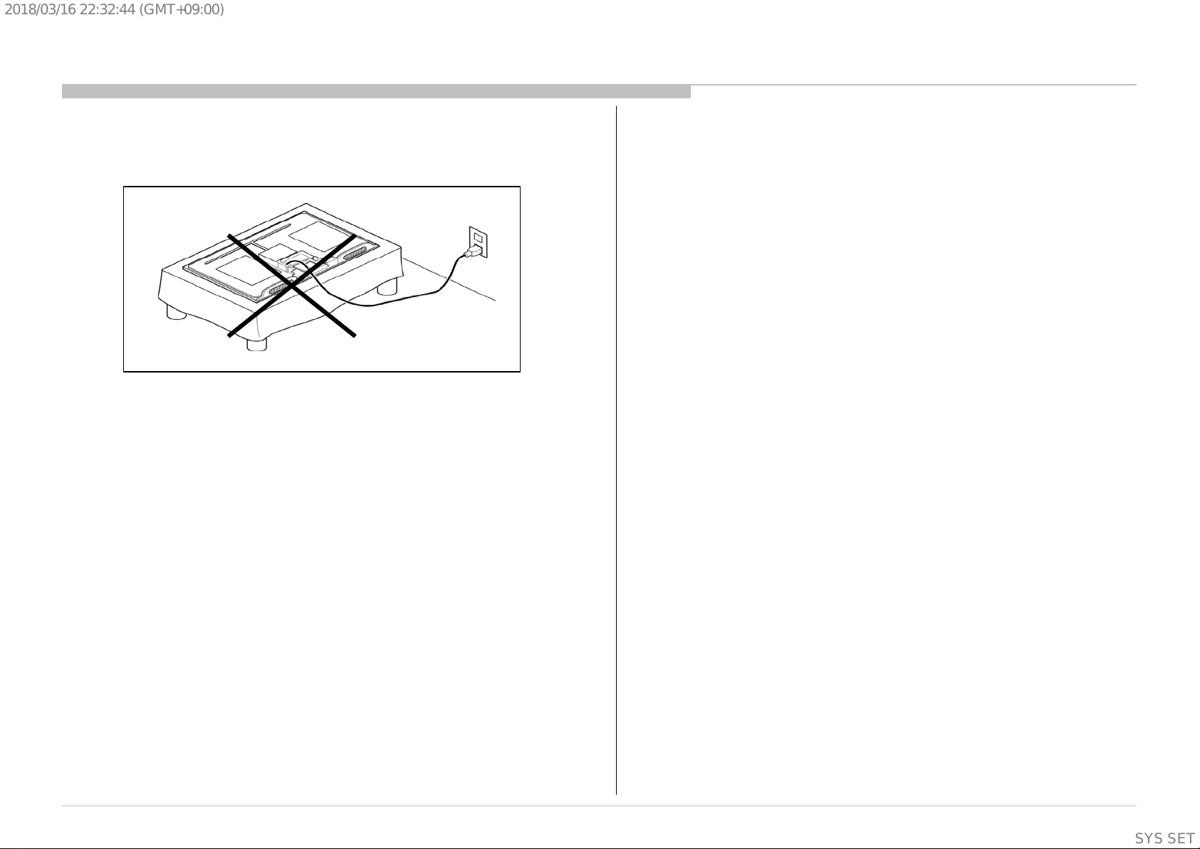
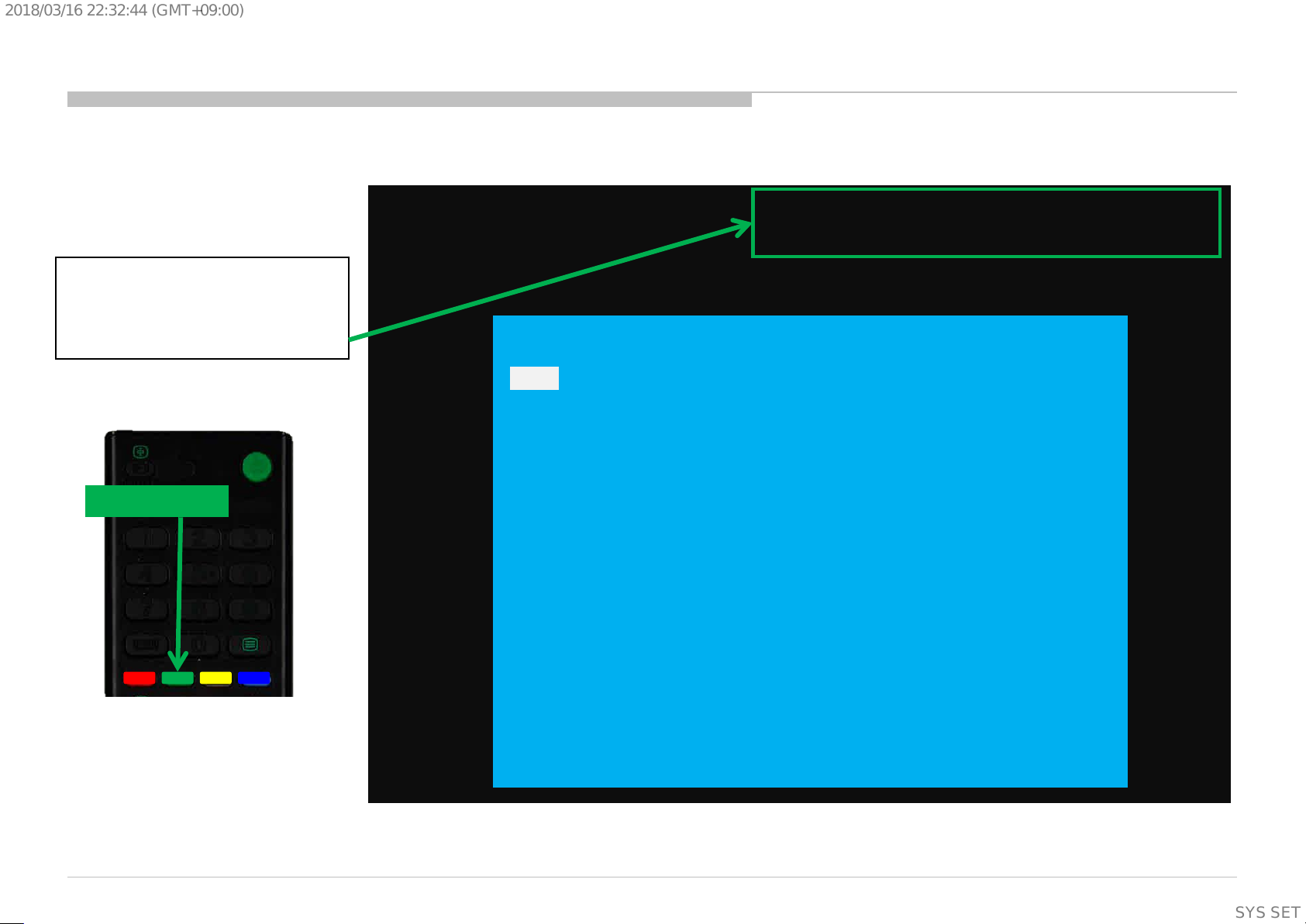
10) During the repair, DO NOT leave the Power On or Burn-in period for
more than 1 hour while the TV is face down on a cloth. Refer Figure 1 .
Figure 1.
1-2-2. Caution for OLED Panel
1) Handling
When repairing the TV set, be sure you are grounded by using a wrist band.
*Do not press on the panel or frame edge to avoid the risk of electric shock.
*Do not scratch or press on the panel with any sharp objects.
*Do not leave the module in high temperatures or in areas of high humidity
for an extended period of time.
*Do not expose the panel to direct sunlight.
*Avoid contact with water. It may cause a short circuit within the module.
*Disconnect the AC power when replacing.
*Always clean the panel with a soft cloth material.
*Use care when handling the wires or connectors. Damaging the wires may
cause a short.
*Protect the panel from ESD to avoid damaging the electronic circuit.
*Do not recommend power-on in the conditions which laid face down the
panel, in repair activity. Refer Figure 1 .
*When transporting by hand, do not put stress on the panel and the frame
around the screen.
Refer to the panel handling chapter of each Service manual,
or the "Transporting" information of the Reference Guide of each model for
how to hold it.
2) OLED Screen
•Although the OLED screen is made with high-precision technology and
99.99% or more of the pixels are effective, black dots may appear or bright
points of light (white, red, blue, or green) may appear constantly on the
OLED screen. This is a structural property of the OLED screen and is not a
malfunction.
•Do not push or scratch the front filter, or place objects on top of this TV
set. The image may be uneven or the OLED screen may be damaged.
•The screen and cabinet get warm when this TV set is in use. This is not a
malfunction.
3) Precautions to Protect the Screen from Damage
Image retention
OLED TV’s are susceptible to image retention (burn-in) due to the
characteristics of the materials used. Image retention may occur if images
are displayed in the same location on the screen repeatedly or over
extended periods of time. This is not a malfunction of the TV. Avoid
displaying images that may cause image retention.
The following are examples of images that may cause image
retention:
•Content with black bars either on the top and bottom and/or the left and
right sides of the screen. (for example, Letterboxed, 4:3 screen, Standard
definition)
•Static images such as photos.
•Video games that might have static content in some part of the screen.
•On-screen menus, program guides, channel logos etc.
•Static content from applications.
•On-screen tickers, such as those used for news and headlines.
6
SYSSET
Page 7
2018/03/1622:32:44(GMT+09:00)
To reduce the risk of image retention:
•Fill the screen by changing [Wide mode] to eliminate the black bars.
Select [Wide mode] other than [Normal].
•Turn off the OSD (On Screen Display) by pressing the DISPLAY button,
and turn off the menus from connected equipment. For details, refer to
the instruction manuals for the connected equipment.
•Avoid displaying static images with bright colours (including white),
clocks or logos on any portion of the screen.
•Set the picture settings based on the ambient conditions. The Standard
Picture is recommended for home use and when viewing content that
often displays the station logos, etc.
The TV has following features to help reduce/ prevent image retention.
Press the HOME button, then select [Settings] – [Picture & Display] –
[Expert panel settings] – the desired option.
Panel refresh
Panel refresh will automatically run to adjust the uniformity of the TV
screen after it has been in use for long periods of time.
Panel refresh can also be performed manually and should only be used if
image retention is very noticeable or you see the following message:
[Panel refresh did not finish...]
Caution:
•The Panel refresh function may affect the panel. As a reference, perform
the Panel refresh only once a year, do not perform it more than once a
year as it may affect the usable life of the panel.
•Panel refresh takes about one hour to complete.
•A white line may be displayed on the screen during the Panel refresh,
this is not a malfunction of the TV.
•Panel refresh will only work when the room temperature is between 10
ºC and 40 ºC.
Pixel shift
Automatically moves the image on the screen to prevent image retention.
Other feature
The screen brightness is automatically reduced when displaying still
images, clocks, bright colours or logos etc.
IMPORTANT REMINDER FOR OLED PANEL REPLACEMENT
When carrying out OLED panel replacement, it is mandatory of a
service center to confirm and record Panel ON time & Panel
Refresh times.
It is because they are indispensable information in order to clarify
responsibility for image retention after panel replacement.
Please refer to the chapter of SELF DIAGNOSIS FUNCTION in this
service manual to find out how to confirm the Panel ON time &
Panel Refresh times in service mode.
1-3. Caution About the Lithium Battery
1) Danger of explosion if battery is incorrectly replaced. Replace only with
the same or equivalent type.
2) Outer case broken battery should not contact to water.
1-4. Safety Check-Out
After correcting the original service problem, perform the following
safety checks before releasing the set to the customer:-
1) Check the area of your repair for unsoldered or poorly soldered
connections. Check the entire board surface for solder splashes and
bridges.
2) Check the inter board wiring to ensure that no wires are pinched or
contact high-wattage resistors.
3)Check all control knobs, shields, covers, ground straps and mounting
hardware have been replaced. Be absolutely certain you have replaced
all the insulators.
7
SYSSET
Page 8
2018/03/1622:32:44(GMT+09:00)
4) Look for unauthorized replacement parts, particularly transistors that
were installed during a previous repair. Point them out to the customer and
recommend their replacement.
5) Look for parts which, though functioning show obvious signs of
deterioration. Point them out to the customer and recommend their
replacement.
6) Check the line cords for cracks and abrasion. Recommend the
replacement of any such line cord to the customer.
7) Check the antenna terminals, metal trim, metalized knobs, screws and all
other exposed metal parts for AC leakage. Check leakage test as described
next.
8. For safety reasons, repairing the Power board and/or Inverter board is
prohibited.
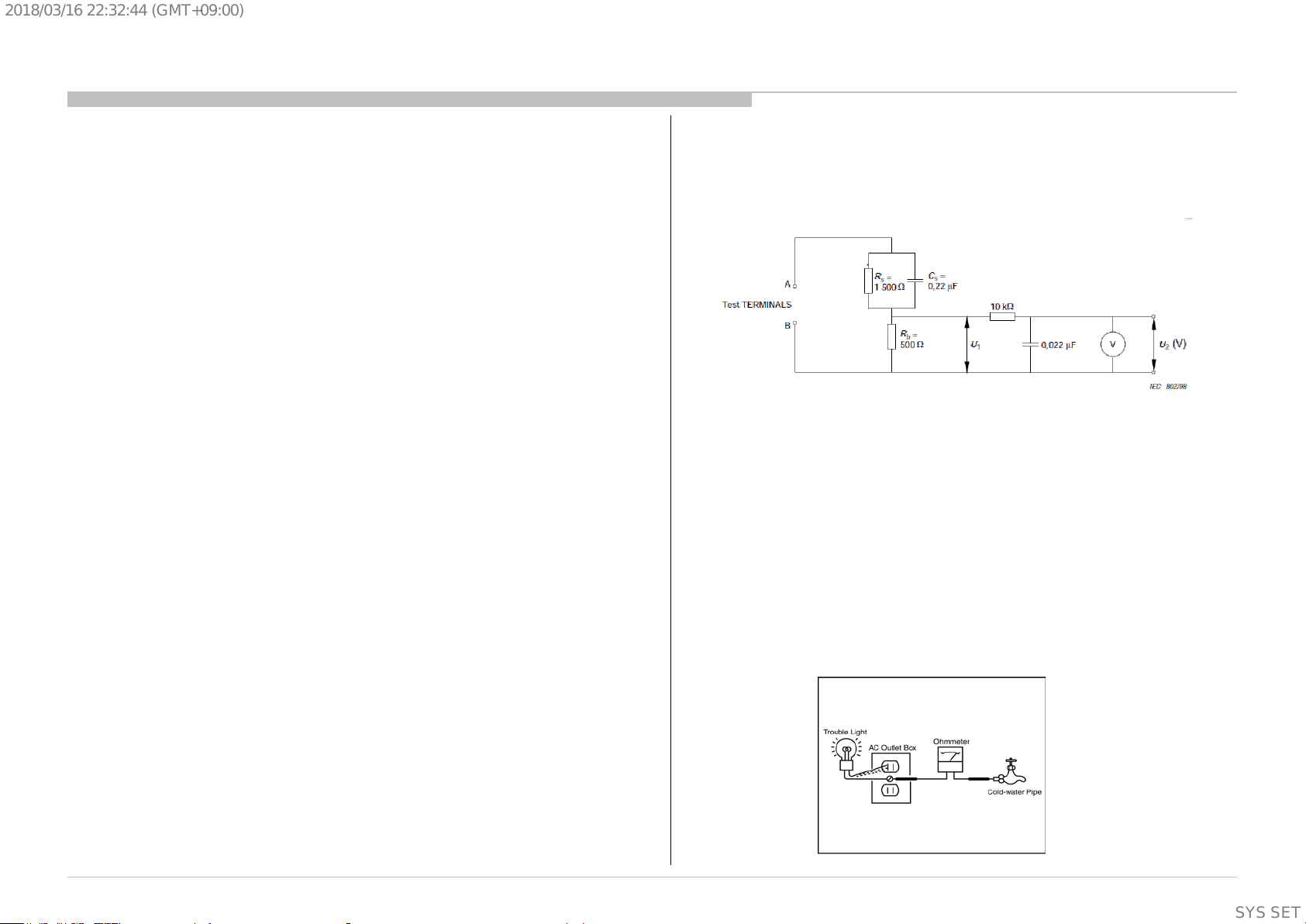
1-5.Leakage Test
(To protect electric shock when customer touch the terminal.)
Leakage current can be measured by V: Voltmeter or oscilloscope (r.m.s. or
peak reading)
Stabilized power supply instrument and isolated voltage transformer:
Use too much current capacity and isolated voltage transformer does not
need to use stabilized power supply equipment.
Specification of RMS volt meter: Input resistance > 1 Mohm, Input
capacitance < 200 pF, Frequency range: 15 Hz – 1MHz . Refer Figure 2.
Isolated type volt -m et er (FLUKE 8921A etc *1)
*1 Not use FLUKE 8920A that connected to protective earth by diode
# Leakage current of measurement instrument is less than 10μArms when
under test equipment AC plug is opened
# Set up the following condition and turn on the set. Applied voltage:
Nominal input voltage (Description on Nameplate)
# Measure the leakage current between one phase conductor and neutral
for terminal A and terminal B.
Read rms value, and then calculate to peak value PEAK VALUE =√2 RMS
VALUE
Comply with the following requirement
Class II equipment (2-pin plug): for each terminal, the worst value of
measurement must not exceed AC 350uA peak).
Note: including AC adaptor, AC adaptor/DC operated unit combination
Figure 2 – Measuring network
for Leakage Current
1-6. How to Find a Good Earth Ground
1) A cold-water pipe is a guaranteed earth ground; the cover-plate
retaining screw on most AC outlet boxes is also at earth ground.
2) If the retaining screw is to be used as your earth ground, verify that it is
at ground by measuring the resistance between it and a cold-water pipe
with an ohmmeter. The reading should be zero ohms.
3) If a cold-water pipe is not accessible, connect a 60- to 100-watt troublelight (not a neon lamp) between the hot side of the receptacle and the
retaining screw. Try both slots, if necessary, to locate the hot side on the
line; the lamp should light at normal brilliance if the screw is at ground
potential (see Figure 3).
Figure 3. Checking for earth
ground.
8
SYSSET
Page 9
2018/03/1622:32:44(GMT+09:00)
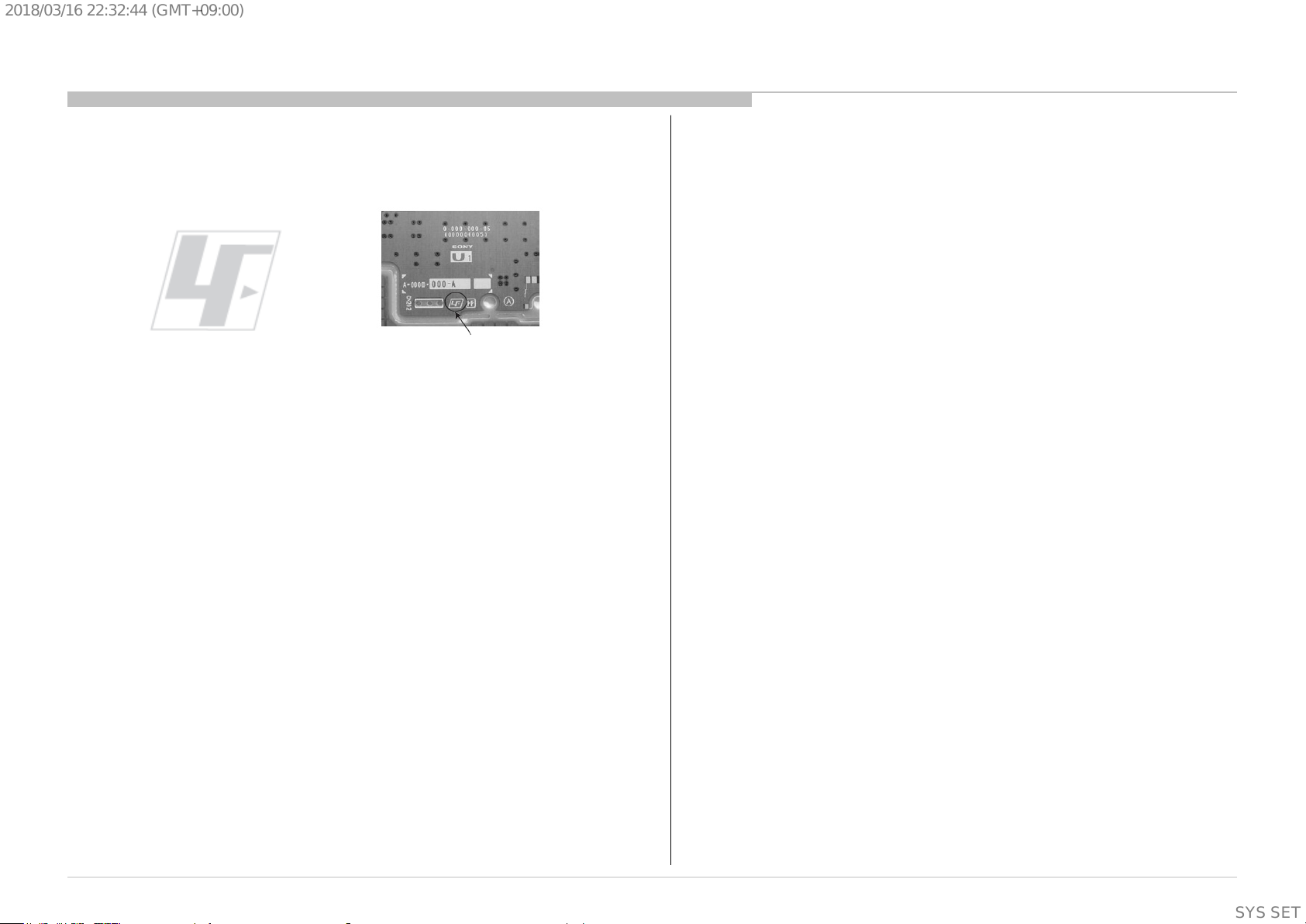
1-7. Lead Free Information
The circuit boards used in these models have been processed using
Lead Free Solder. The boards are identified by the LF logo located
close to the board designation.
The servicing of these boards requires special precautions. It is
strongly recommended to use Lead Free Solder material in order to
Figure 4: LF Logo
Figure 5: LF logo on circuit board
guarantee optimal quality of new solder joints.
9
SYSSET
Page 10
2018/03/1622:32:44(GMT+09:00)
The units in this manual contain a self-diagnostic function. If an error occurs, the Smar t C ore R ed LE D will automatically begin to flash.
The number of times the LED flashes translates to a probable source of the problem.
A definit ion of the Smart Core Red LED flash indicators is listed in the instruct ion manual for the user’s knowl edge and reference.
If an error symptom cannot be reproduced, the r emote c ommander can be used to review the failure occurrenc e data stored in memory to
reveal past problems and how often these pr oblems occur.
DIAGNOSTIC TEST INDICATORS
When an error occurs , the Smart Core Red LED w il l flash a set number of times to indicate the poss i ble cause of the problem.
If there is more than one error , the LED wil l identify the first of the problem areas .
Result for all of the foll owing diagnostic items are displayed on screen.
If the screen display s a “ 0”, no error has occ urr ed .
Self Diag. Quick Reference (LED blinking)
SECTION 2
SELF DIAGNOSTIC FUNCTION
Smart Core RED
LED blinking count
2x <B/G> Main 12V over voltage [MAIN_POWER]
3x
4x <T/B>TCON internal error/TCON I2C communication error[LD_ERR]
5x
6x <G/B> G board error[BACKLIGHT]
7x
8x <B> 4KBE Error (4KBE WDT)
Detection Items
<B/G> Main 5.0V failure [DC_ALERT]
<B/S/G> Audio amp. protection [AUD_ERR]
<P/T/G/B> Panel ID EEPROM I2C No ACK
(Also panel power failure is a suspect) [P_ID_ERR]
<T/B>Data corruption in EEPROM[P_ID_ERR]
<B/P> Over temperature protection [TEMP_ERR]
<B> Temp. sensor I2C No ACK [TEMP_ERR]
Blue italic: detect at startup sequence only.
<G>: Power supply board,
<B>: Main board,
<T>: T-con board,
<P>: Panel module,
<S>: Speaker,
<Tu>: Tuner board,
10
SYSSET
Page 11
2018/03/1622:32:44(GMT+09:00)
Self Diag. Quick Reference (Not LED blinking [Record Only])
Error Item
( Not LED blinking
[Record Only])
TU_DEMOD
TCON ERR
AUD_ERR_I2C <B> Audio amp I2C communication failure
Detection Items
<B/Tu> Tuner & Demodulator I2C communication failure
Tuner board set detect signal monitoring
None
*CR is shutdown by I2c communication failure[LD_ERR]
<G>: Power supply board,
<B>: Main board,
<T>: T-con board,
<P>: Panel module,
<S>: Speaker,
<Tu>: Tuner board,
11
SYSSET
Page 12
2018/03/1622:32:44(GMT+09:00)
Self Diagnosis Service Menu and Display
Entry (Self Diagno sis D ispl ay)
- Go to the standby by a remote.
- Push the buttons sequentially:
<Display><5><Vol-><Power>
Exit
-If you want to finish service mode app, do AC OFF/ON
→ *Service mode app is disable perfectly
-if you want to move home menu, push <HOME>button
→ *Service mode app do background(not disabl e perfectly )
Format of error timestamps
YYMMDDhhmmss (in UTC)
Example:
120823132523 -> Aug 23 2012 13:25:23 UTC
* Only when time is set, an error timestamp
is saved.
Smart
Core Red
LED
blinking
count
Error Item
Error count
SELF CHECK
Back
<<
002 MAIN POWER 000000000000 000000000000 000000000000 000
003 DC ALERT 000000000000 000000000000 000000000000 000
003 AUD ERR 150101000018 150101000018 150101000018 003
003 AUD ERR I2C 000000000000 000000000000 000000000000 000
003 TU DEMOD 150101000218 150101000223 150101000105 003
004 LD ERR 000000000000 000000000000 000000000000 000
004 BCM ERR 000000000000 000000000000 000000000000 000
005 TCON ERR 150101000504 000000000000 000000000000 001
005 P ID ERR 000000000000 000000000000 000000000000 000
006 BACKLIGHT ERR 000000000000 000000000000 000000000000 000
007 TEMP ERR 150101000200 150101000002 000000000000 002
008 4KBE ERR 000000000000 000000000000 000000000000 000
00005 00414 00002
[Home]Exit
Error
timestamp
for last
recorded
error
Error
timestamp
for second
last
recorded
error
Error
timestamp
for 3rd
last
recorded
error
Panel Operation Time clear
<7> -> <0>
Timestamps and Error Count clear
<8> -> <0>
Total Operation Time and Boot Count clear
<9> -> <0>
Total Operation Time [hr] – Boot Count – Panel Operation Time [hr]
•Panel Operation Time is recorded every 30 min, but Total Operation
Time is recorded every 1 hr.
Therefore, the panel op. time might become larger than the total op. time.
12
SYSSET
Page 13
2018/03/1622:32:44(GMT+09:00)
Self Diagnosis Display
How to confirm
- Panel ON time
- Panel Refresh times
Enter Self Diagnosis D ispl ay.
Then Push ‘Green button’ on
remote controller.
Then display upper right corner.
Green button
1
4 5 6
7
2 3
8
9
Panel ON time[hour] /Panel Refresh times[times]
Ex) 100 / 20
SELF CHECK
<<
Back
002 MAIN POWER 000000000000 000000000000 000000000000 000
003 DC ALERT 000000000000 000000000000 000000000000 000
003 AUD ERR 150101000018 150101000018 150101000018 003
003 AUD ERR I2C 000000000000 000000000000 000000000000 000
003 TU DEMOD 150101000218 150101000223 150101000105 003
004 LD ERR 000000000000 000000000000 000000000000 000
004 BCM ERR 000000000000 000000000000 000000000000 000
005 TCON ERR 150101000504 000000000000 000000000000 001
005 P ID ERR 000000000000 000000000000 000000000000 000
006 BACKLIGHT ERR 000000000000 000000000000 000000000000 000
007 TEMP ERR 150101000200 150101000002 000000000000 002
008 4KBE ERR 000000000000 000000000000 000000000000 000
;
00005 00414 00002
[Home]Exit
13
SYSSET
Page 14
Before yo u make the service call…
1. Confirm the symptom from the customer .
2. Select that symptom from the chart.
3. Bring all the boards and c abl es listed for that symptom.
4. Follow the troublesho oti n g charts in the technical guides to isol ate the board.
5.
RED DOT: Most likely defective par t
BLUE TRIANGLE: Secondary possible defectiv e part
BLACK TEXT: Board that may correct the symptom
FRCT
C_I2
R_I2
LED & does not
Stationary
dots
No Remote
(Communication)
2018/03/1622:32:44(GMT+09:00)
T r i ag e C har t
Chart Colour Code
SECTION 3
TROUBLESHOOTING
Symptoms - Shutdown. Power LED
blinking red diagnostics sequences
Reference
2 3 4 5 6 7 8
B* Board
G* Board
H* Board
Actuater
(Panel module)
Speaker
(Sub woofer)
Wifi & BT
Module
V By One FFC
Tcon
(Panel module)
OLED Panel
(Panel module)
Problem
Power Power Tcon
Audio
Panel
Panel
Power
TEMP 4KBE
Symptoms - no shutdown
Error log record only
TU_
TCO
DEM
N_E
OD
RR
AUD
_ER
4KPQ_ERR_
C
I2C
C
Power
No White Power
reponse to
remote (Dead
No
Set)
Video
- missing or distorted
No video
colored
lines or
One of
Inputs
NO RF
input
Remote Network Audio Smart Core Bluetooth (BT)
No video
all Inputs
Wireless
can't connect
No Audio
Smart Core no LED
(Set is still alive)
Bluetooth / Voice
Remote can't
connect
14
SYSSET
Page 15
2018/03/1622:32:44(GMT+09:00)
TROUBLESHOOTING Flow
1.0 No Power
BM2A Board Model
No Power
Check STBY 3.3V
C408
near CN400
on BM2A board
OK
BM2A Board
NG
Replace
Between G* Board to
BM2A Board Harness
OK
Harness
u-Com Failure
DDCON/LDO
NG
G* Board
Main Device Failure
15
SYSSET
Page 16
2018/03/1622:32:44(GMT+09:00)
1.2 No Power u-com Failure
+3.3V_STBY
#pin6
Vdd u-com
supply
voltage
#pin9
P-on u-com control signal path summary
BM2A
PGOOD_1
DDC : +1.0V_M2 (IC604)
TCON_P_ON
Delay (IC408)
G-Board
+12V_MAIN
AC_OFF_DET_OUT
from SOC BE (IC4000)
R426
R427/Q410
BL_ON
POWER_ON
R446
GND
R439
#pin7
#pin10
#pin16
12V_MON
ADC port
#pin11
DC_MON
ADC port
#pin12
P_ON_#1
DDCs : +1.8V_TU (IC405), +1.0V_BE (IC4003)
DDCs : +5V_MAIN (IC402), +3.3V_MAIN (IC403),
P-on u-com
IC401
#pin13
P_ON_#2
+1.5V_BE (IC4001), +1.1V_BE (IC4002)
LDOs : +1.05V_M2_A_1 (IC603), +1.05V_M2_A_2
(IC606),
VCC3IO_EMMC (IC607), +1.8V_BE (IC 4004)
DDC : +12V_LNB (Q408/Q409)
#pin18
#pin2
#pin14
#pin3
#pin20
#pin8
P_ON_HL
OPWRSB
ORESETB
DC_OFF_DET
X_SYSTEM_RST
BE_PANEL_PWR_ON_#2
USB VBUS SW (IC3406, IC3407, IC3408)
SOC Muffin 2 (IC1000)
Tuner (TU2802/TU2803)
SOC BE (IC4000)
GND
16
SYSSET
Page 17
2018/03/1622:32:44(GMT+09:00)
1.2 No Power u-com Failure
START
Check VDD
C506 Voltage.
Is the voltage >3.0V?
no
Check +3.3V_STBY Line (C408, CN400 #9pin)
Check 12V_MON
R446 Voltage.
Is the voltage >2.6V?
no
Check +12V_MAIN Line
(from G board).
Check “AC_OFF_DET_OUT”
(from BE SOC IC4000)
Check “AC_DET_IN”
(C407, CN400 #16pin
from G board)
yes
Check TYPE_DET
R428 Voltage.
Is the voltage 2.6±0.2V?
yes
Check OPWRSB
R443 Voltage.
Is the voltage 0V?
yes
Check POWER_ON
R526 or P-on u-com #pin10
Is the voltage >3.0V?
yes
no
no
no
Type Detection Circuit problem.
Check TYPE_DET Line (R521, R522, R523).
SOC
Muffin 2
problem
Try AC Off and On after few minutes.
If #pin10 keep Low, change IC401.
If #pin10 goes High few seconds and downs to Low,
Check +12V_MAIN Line (from G board).
yes
Check DC_OFF_DET
R448 or P-on u-com #pin3
is >3.0V?
yes
Check P_ON_#1
CL418 or P-on u-com #pin12
is >3.0V?
yes
Check PGOOD_1
R440 Voltage.
Is the voltage >3.0V?
Continue next page…
no
Change IC401
no
Change IC401
no
1.3 No POWER - DDCON/LDO
Check 1.0V DDCON (IC604)
17
SYSSET
Page 18
2018/03/1622:32:44(GMT+09:00)
1.2 No Power u-com Failure
Previous page
Check P_ON_#2
CL417 or P-on u-com #pin13
is >3.0V?
yes
Check P_ON_HL
CL414 or P-on u-com #pin18
is >3.0V?
yes
Check ORESETB
CL416 or P-on u-com #pin14
Is the voltage >3.0V?
yes
Check X_SYSTEM_RST
CL412 or P-on u-com #pin20
Is the voltage >3.0V?
no
no
no
no
Change IC401
Change IC401
Change IC401
Change IC401
Check BL_ON
R527 or P-on u-com #pin7
Is the voltage >3.0V?
yes
END
u-com IC401 is working OK
no
Change IC401
yes
Check
BE_PANEL_PWR_ON_#2
R441 or P-on u-com #pin8
Is the voltage >3.0V?
yes
no
Check “X_BE_RST” (from SOC Muffin).
*If X_BE_RST is >3.0, SOC BE(IC4000) problem.
Otherwise, SOC Muffin(IC1000) problem.
18
SYSSET
Page 19
-
2018/03/1622:32:44(GMT+09:00)
1.3 No Power DDCON/LDO
Check item summary
Board IC Ref Voltage supply Output ref. Enable pin Enable source Fuse Vcc ref.
BM2A IC402 +5V_MAIN/+5V_AUDIO C430 R455 P-on u-com IC401 #pin13 F400 C423
BM2A IC403 +3.3V_MAIN/+3.3V_AUDIO C445 R465 P-on u-com IC401 #pin13 F401 C436
BM2A IC405 +1.8V_TU C463 IC405 #PIN5 P-on u-com IC401 #pin12 F403 C461
BM2A IC601 +1.5V_DDR C609 C605 R603 (3.3V or 5V) - C602
BM2A IC602 +1.05V_M2_STBY C611 IC602 #PIN3 C610 (+3.3V _STBY) - C610
BM2A IC603 +1.05V_M2_A_1 C613 IC603 #PIN3 P-on u-com IC401 #pin13 - C612
BM2A IC604 +1.0V_M2 C625 R623 P-on u-com IC401 #pin12 F600 C618
BM2A IC605 +1.05V_M2_ST_ET C631 IC605 #PIN3 M2 IC1000 #AP34 - C630
BM2A Board Model
BM2A IC606 +1.05V_M2_A_2 C633 IC606 #PIN3 P-on u-com IC401 #pin13 - C632
BM2A IC607 VCC3IO_EMMC (1.8V) C635 IC607 #PIN3 P-on u-com IC401 #pin13
BM2A IC4001 +1.5V_BE C4007 IC4001 #PIN5 P-on u-com IC401 #pin13 F4000 C4005
BM2A IC4002 +1.1V_BE C4014 IC4002 #PIN5 P-on u-com IC401 #pin13 F4001 C4012
BM2A IC4003 +1.0V_BE C4027 R4020 P-on u-com IC401 #pin12 F4002 C4020
BM2A IC4004 +1.8V_BE C4001 IC4004 #PIN3 P-on u-com IC401 #pin13 - C4000
(Supplementary
information)
C634
19
SYSSET
Page 20
2018/03/1622:32:44(GMT+09:00)
1.3 No Power DDCON/LDO
DDCON check
Check IC402 Vcc voltage
Is voltage >12V?
Check Vcc voltage
Is voltage >4V?
START
C423
yes
C602
yes
no
no
Check Vcc voltage
C602
Is voltage >3V?
yes
Check
D601
Is diode alive?
yes
no
no
BM2A Board Model
IC Ref Voltage supply
IC601 +1.5V_DDR
Check
D600
Is diode alive?
yes
Change D601
Check +5V_MAIN DDCON (IC402)
no
Change D600
Check +3.3V_STBY.
G* board
Check Enable
IC600 #pin1
Is voltage >2.5V?
yes
Change DDCON
IC601
no
Change IC600
20
(Supplementary
information)
20
SYSSET
Page 21
2018/03/1622:32:44(GMT+09:00)
1.3 No Power DDCON/LDO
DDCONs check
IC Ref Voltage supply
IC402
+5.0V_VBUS/+5V_MAIN
+3.3V_STBY (AC-ADP only)
IC403
/+3.3V_MAIN
Q407 +3.3V_MAIN
IC405 +1.8V_TU
IC601 +1.5V_DDR
IC604 +1.0V_M2
IC4001 +1.5V_BE
START
Check fuse
F4xx / F40xx/F6xx
Is fuse OK?
yes
Check Vcc voltage
C4xx / C40xx/C6xx
Is voltage >12.0V?
yes
BM2A Board Model
Please refer page-19 for Ref number.
no
Change Fuse
no
1) Check POWER_ON P-on u-com #pin10
(Refer 1.2 No Power U-Com Failure)
2) Check G* board
IC4002 +1.1V_BE
IC4003 +1.0V_BE
Check Enable pin
voltage
Is voltage >2.5V?
yes
Change DDCON IC
no
1.2 No Power U-Com Failure
or
Enable source
21
(Supplementary
information)
21
SYSSET
Page 22
2018/03/1622:32:44(GMT+09:00)
1.3 No Power DDCON/LDO
LDOs check
IC Ref Voltage supply
IC602 +1.05V_M2_STBY
IC603 +1.05V_M2_A_1
IC605
+1.05V_M2_ST_ET
IC606 +1.05V_M2_A_2
VCC3IO_EMMC
IC607
(1.8V)
IC4004 +1.8V_BE
START
yes
Check Vcc voltage
C4xxx or C6xx
Is voltage >3V?
yes
Check Enable pin
voltage
Is voltage >3V?
yes
no
no
BM2A Board Model
Please refer page-19 for Ref number.
Check +3.3V_DDC_OUT
DDCON (IC403)
or
+3.3V_STBY (G* board)
1.2 No Power U-Com Failure
or
Enable source
Change LDO IC
22
(Supplementary
information)
22
SYSSET
Page 23
2018/03/1622:32:44(GMT+09:00)
1.4 NO POWER-Muffin2 Failure
Muffin2 Fail Suspected
Muffin2 LOG is
displayed
No
Power uCom and
DDCON/LDO OK?
Yes
Crystal X1000
Is there 24MHz?
Yes
Muffin reset released?
ORESETB=High
Yes
No
No
No
W rite DD R check
bootloader
Follow 1.2&1.3
Replace crystal
Check uCom
Follow 1.2
Is there DDR error?
No
Check Muffin Log
related to eMMC
Is there “CRC error”
No
Store SW log, check SW
behaviors.
Yes
Replace DDR
Yes
Replace eMMC
Yes
eMMC clock present?
No
Replace Muffin
Yes
W rite DD R check
bootloader
Is there DDR error?
No
eMMC
data corruption
Yes
Replace DDR
23
SYSSET
Page 24
2018/03/1622:32:44(GMT+09:00)
1.5 NO POWER-Muffin2 Replacement
Muffin2
replacement
flow
eMMC erase
Muffin2 replacement
Data on eMMC need
to be erase first before
changing Muffin
If cannot be erased,
erase after replacing
Muffin
SW write
(Supplementary
information)
24
SYSSET
Page 25
2018/03/1622:32:44(GMT+09:00)
2.0 LED Blinking: 2x (Main power Error)
BM2A
2-time blinking
Check “+12V_MAIN”
at pin 1 1/13 of CN400
on BM2A Board,
Vol tage > 13.2V ?
No
BM2A Board
Yes
G* Board
25
SYSSET
Page 26
2018/03/1622:32:44(GMT+09:00)
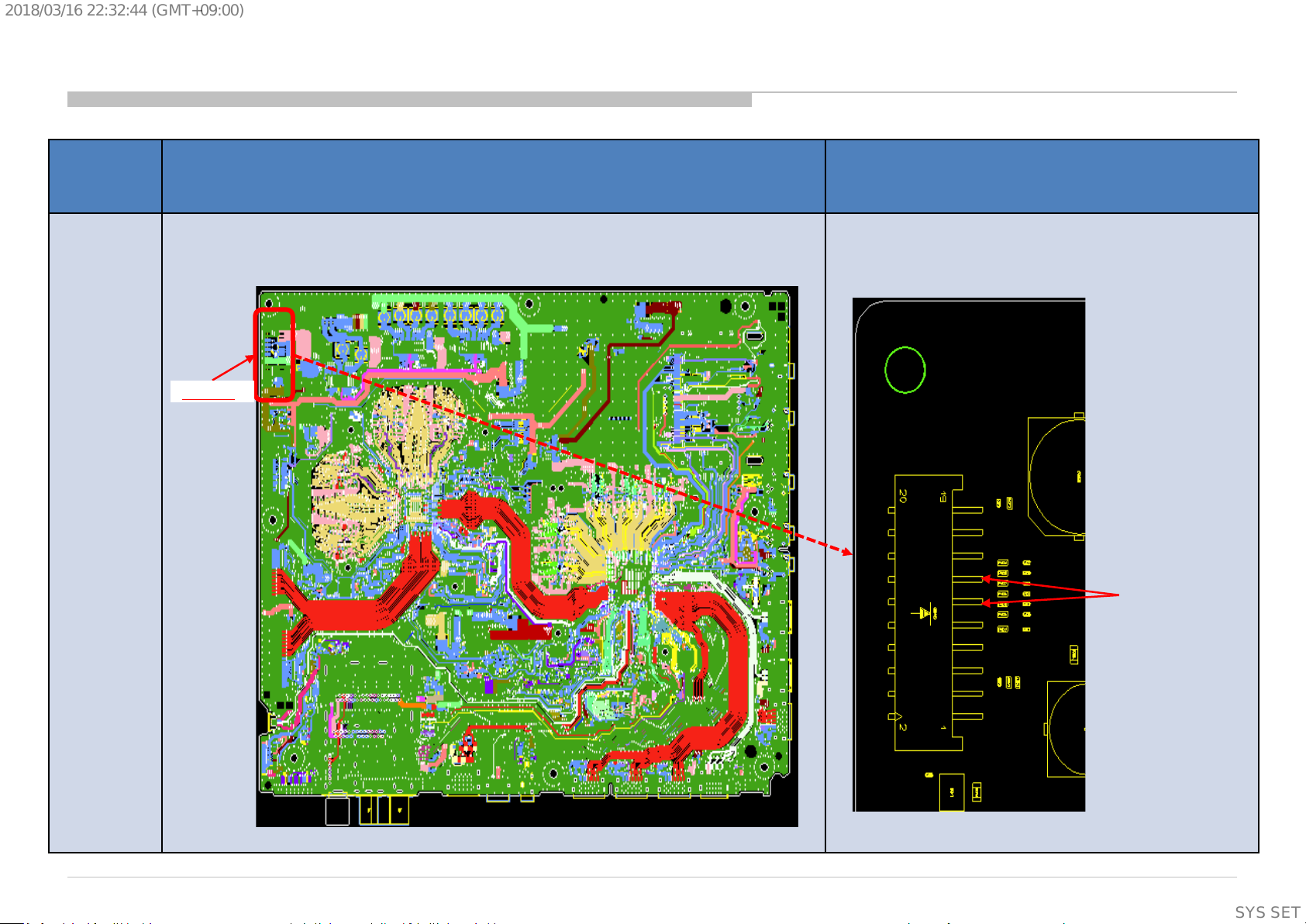
Check point for BM2A
Name Board PWB (A side) Detail
CN400
BM2A
+12V_MAIN
26
SYSSET
Page 27
2018/03/1622:32:44(GMT+09:00)
2.1 LED Blinking: 3x (DC Alert Error)
BM2A
Check “POWER_MAIN”
at pin 17/19 of CN400
Voltage = 18.0~20.0V or
22.5~24.5V ?
3-time blinking
(DC Alert)
on BM2A board,
OK
Check “+5.0V_VBUS”
at C431 on BM2A board
4.959V<Voltage<5.285V?
OK
Retry
NG
G Board
Detail of 3x LED Blinking
Error Item Number of STBY
Trinity DC_ALERT 3 Main board 5V power rail monitoring
AUD_ERR 3 Audio amp error detection
Trinity3 Board: BM2A
LED flashing
NG
BM2A Board
Description
(Supplementary
information)
27
SYSSET
Page 28
2018/03/1622:32:44(GMT+09:00)
Check point for BM2A
Name Board PWB (A side) Detail
CN400
BM2A
+5.0V_VBUS at C431
POWER_MAIN
Pin17/19 of CN400
(Supplementary
information)
28
SYSSET
Page 29

2018/03/1622:32:44(GMT+09:00)
2.2 LED Blinking: 3x (Audio Error)
LED 3x blinking
(Audio Error)
Power Off Check
Go to 3.3
Power On Check
Go to 3.4
Detail of 3x LED Blinking
Replace
G Board
NG
Measure the Speaker
impedance by multi-meter
Less than 3Ω ?
No
Speaker Harness
OK
Yes
G Board
Replace
Speaker
* In case of Actuator, replace Panel module.
Error Item Number of STBY
Trinity DC_ALERT 3 Main board 5V power rail monitoring
AUD_ERR 3 Audio amp error detection
Trinity3 Board: BM2A
LED flashing
Description
(Supplementary
information)
29
SYSSET
Page 30

2018/03/1622:32:44(GMT+09:00)
2.3 LED BLINKING 4x (TCON Internal Error/TCON I2C Communication Error)
BM2A
4-time blinking
(TCON Internal/
TCON I2C Communication)
OK
FFC Cable
Replace FFC Cable
Detail of 4x LED Blinking
Trinity
3
Error
Item
LD_ERR 4 CR TCON internal error
Number of STBY
LED flashing
(B<->TCON)
NG
BM2A Board
(TCON I2C Communication)
4
Low
Check
“LD_ERR_DET” Voltage
at CL4458 on BM2A Board
High
(TCON Internal)
Segment Description
CR TCON I2C communication error
Replace TCON board
OK
TCON Board
NG
Panel
Trinity3 Board: BM2A
(Supplementary
information)
30
SYSSET
Page 31

2018/03/1622:32:44(GMT+09:00)
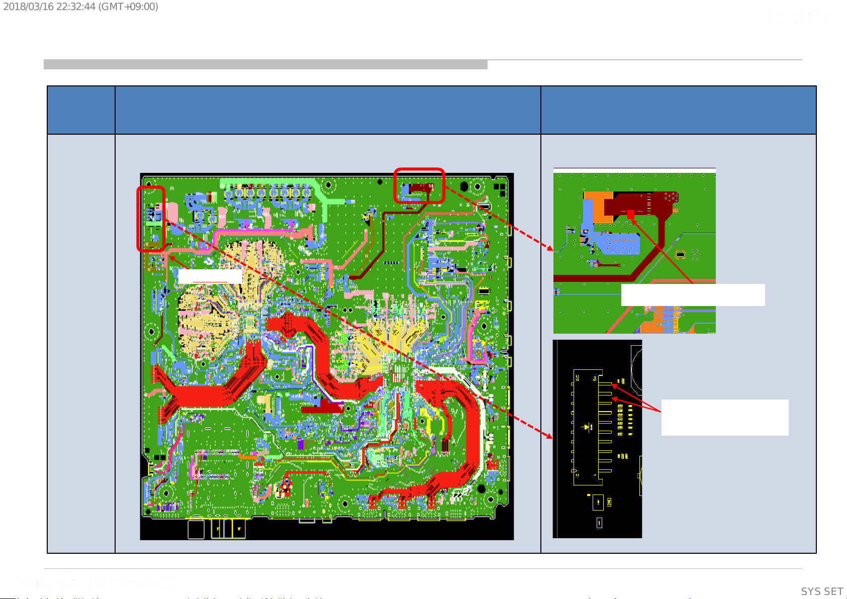
Check point for BM2A
Name Board PWB (A side) Detail
BM2A
CL4458
(Supplementary
information)
31
SYSSET
Page 32

2018/03/1622:32:44(GMT+09:00)
2.5 LED BLINKING: 5x (Panel ID Read Error)
BM2A
5-times blinking
Check
“+12.5V_TCON”
on T-CON Board
OK
Replace the Harness
Between G Board
and BM2A
NG
Replace
the V-By-One FFC
NG
Symptom
improve
Symptom
improve
Replace
G Board
NG
Harness
V-By-One FFC
OK
G Board
Replace
BM2A Board
Symptom
improvement
BM2A Board
NG
Replace
Panel (T-con)
Symptom
improvement
Panel (T-con)
NG
32
SYSSET
Page 33

2018/03/1622:32:44(GMT+09:00)
2.6 LED BLINKING: 6x
BM2A
6-times blinking
Check Voltage of
“BL_ERR_DET”
at CL4459 on BM2A
Low
High
harness/connection
G board to BM2A
Harness /
Connection OK
Check
Harness /
Connection
broken
Replace G board.
Replace
harness
No
improvement
G board
No
improvement
Replace
BM2A
No
Improvement
Symptom
Improvement
Improvement
Symptom
Improvement
Harness
Symptom
G board
BM2A Board
Replace
Panel
Symptom
Improvement
Panel
(Supplementary
information)
33
SYSSET
Page 34

2018/03/1622:32:44(GMT+09:00)
Check point for BM2A
Name Board PWB (A side) Detail
BM2A
CL4459
34
SYSSET
Page 35

2018/03/1622:32:44(GMT+09:00)
2.7 LED BLINKING: 7x (Temperature Error)
BM2A
7-time blinking
Setting
circumstance is OK?
Temperature,
Ventilation, etc.
Yes
No
Set to another
location, etc.
2.8 LED BLINKING: 8x (4KBE Error)
BM2A
8-time blinking
Replace
BM2A Board
Replace BM2A
Board, and Aging a few
hours
Symptom
improvement
BM2A Board
NG
Panel
35
SYSSET
Page 36

2018/03/1622:32:44(GMT+09:00)
3.0 No Sound
No Sound
Without LED 3x
AV receiver is connected
to HDMI in ?
No
[Speakers] setting is
[Audio System] ?
No
Headphone is connected to
HP/Audio Out terminal ?
No
[Sound]→
[Headphone Speaker Link]
setting is [On] ?
Yes
Yes
Yes
Yes
Select [External Inputs]→
[BRAVIA Sync Settings] →
[BRAVIA Sync Control]→[off]
Change the setting to
[TV Speakers]
Disconnect the Headphone
Change [Sound]→
[Headphone Speaker Link]
to [Off], OK ?
No
No sound only
Analog RF and Digital RF ?
No
No sound only HDMI ?
No
Go to
3.1 No Sound Audio
Yes
Yes
Go to
3.7 No Sound Tuner
Go to
3.8 No Sound HDMI
No
Go to
3.3 Power Off Checking
Yes
Replace BM2A board
HP/Audio out termi nal or Headphone
detect GPIO may be broken
36
SYSSET
Page 37

2018/03/1622:32:44(GMT+09:00)
3.1 No Sound Audio
No Sound
Audio
Replace BM2A
OK
Finish
NG
Go to
3.4 No Sound Power On Check
37
SYSSET
Page 38

2018/03/1622:32:44(GMT+09:00)
3.3 No Sound Power Off Check
Power Off Check
From 2.2
(1) BM2A-PWB
Fuse
(F3200,F3201,F3202)
broken?
No
Yes
Power Off Check
From 3.0
Confirm the speaker
harness
Cut or shorted
to the chassis ?
Yes
Replace Speaker
Harness
(2) BM2A-PWB
PVDD-GND(C3288)
short ?
No
(3) BM2A-PWB
LDO out(C3287)
short ?
No
Yes
Yes
Replace BM2A-PWB
NO
Measure the Speaker
impedance by multi-meter
Less than 3Ω ?
NO
Yes
Replace
Speaker
* In case of Actuator, replace Panel module.
(Supplementary
information)
38
SYSSET
Page 39

2018/03/1622:32:44(GMT+09:00)
3.4 No Sound Power On Check
(4) POWER_A U * check
POWER_AU is supplied to
before LED 3x blinking?
Power On Check
From 2.2/3.1
BM2A for a moment
No
*Power AU is same as PVDD
Yes
No
Replace G-PWB
OK ?
No
Return to 2.2
Yes
Finish
39
SYSSET
Page 40

2018/03/1622:32:44(GMT+09:00)
3.5 No Sound Audio HP/Audio out
No Sound Audio
HP/Audio out
Replace BM2A-PWB
40
SYSSET
Page 41

2018/03/1622:32:44(GMT+09:00)
3.7 NO SOUND: @ TUNER
No Sound with normal picture
NO
Only RF tuner input?
YES
Check IC1000 (SOC)
Please refer Audio
troubleshooting
41
SYSSET
Page 42

2018/03/1622:32:44(GMT+09:00)
3.8 NO SOUND: HDMI 1/2/3/4
No Sound
Check the picture
OK
Check the mode
of Source equipment
HDMI
Does this model have
Analog Audio In
(Stereo minijack)?
NO
Check Sound by other TV set
which is same model
NG
NG
Refer to 4.5 HDMI NO PICTURE
DVI
YES
“HDMI/DVI Audio Source”
Auto or HDMI Audio
OK
Does this model have
Analog Audio In
(Stereo minijack)?
setting is?
YES
Connect Stereo minijack cable between Source and the TV, and
Change “HDMI/DVI Audio Source” to Auto or Analog Audio In.
No
Change the mode of Source equipment to HDMI
Analog Audio In
Change “HDMI/DVI Audio Source” to Auto or HDMI Audio In
Refer to 3.0 No Sound Audio
Is Distributor used ?
YES
Connect Source
equipment directly
NO
Check Source equipment
by Reference TV set
(For example, RB2, RB1)
NG
Check the settings of
Source equipment
OK
Change B-Board.
And inform the designer of it
42
SYSSET
Page 43

2018/03/1622:32:44(GMT+09:00)
4.0 No Picture
No Picture
Got Any Normal
Display?
Yes
Check Other
Portion:
Ext. Video Input -
HDMI - No Picture
No
No Picture
Check Smart Core
Behavior
(Blinking)
Yes
4x
5x
6x
No
4x Blinking
5x Blinking
6x Blinking
Replace
the V by One FFC
Harness
Symptom
improvement
V by One FFC
Harness
NG
Replace
the main Board
Symptom
improvement
Main board NG
NG
Panel
(T-CON)
Tuner - No Picture
43
SYSSET
Page 44

2018/03/1622:32:44(GMT+09:00)
4.1: Video Analog Signal Path
Video
(Side Mini Jack)
CVBS3P
VIDEO2_DET
L36:CVBS3P
G16:GPIO66
M2
IC1000
44
SYSSET
Page 45

2018/03/1622:32:44(GMT+09:00)
4.2: No Picture (BM2A)
No Picture
Video
No Picture
NG
Check if input OSD
is GREY OUT
OK if it is highlighted
OK
* Check J2600
Connection,
VIDEO2_DET
At R2612
OK (Vpp: 3.3 V)
** Detailed check all
parts at VIDEO2_DET
signal Path [R2611]
OK (Vpp: 3.3V)
NG (Vpp: 0V)
NG (Vpp: 0V)
Condition Actions to be taken
Muffin [IC1000]
Problem
J2600 Connector
Problem
J2600 Connectivity
Problem
Parts Broken
Refer to IC troubleshooting for
further investigation
Change Connector
Change Part
NG (Vpp: 0 V)
Check wave between
C2609 and IC1000
OK (Vpp: 1 V)
Muffin [IC1000]
Problem
J2600 Connector
Problem
* OK Condition : No solder splash can be seen
NG Condition : Solder splash can be seen
[All voltage measurement using Oscilloscope]
** Detailed check all parts
at CVBS3P signal path
[R2642/R2631/R2607
/C2621/C2609/VD2604]
J2600 Connectivity
Problem
NG
OK
Parts Broken
** OK Condition : No part short-circuited
NG Condition : Part short-circuited
45
SYSSET
Page 46

2018/03/1622:32:44(GMT+09:00)
4.2/4.3: Input Skip function (BM2A)
Input Signal Non-Detect
(Typical)
Video VIDEO2_DET
0V 3.3V
IC1000 G16GPIO66
Video
(Side Mini Jack)
Detect
(Typical)
46
SYSSET
Page 47

2018/03/1622:32:44(GMT+09:00)
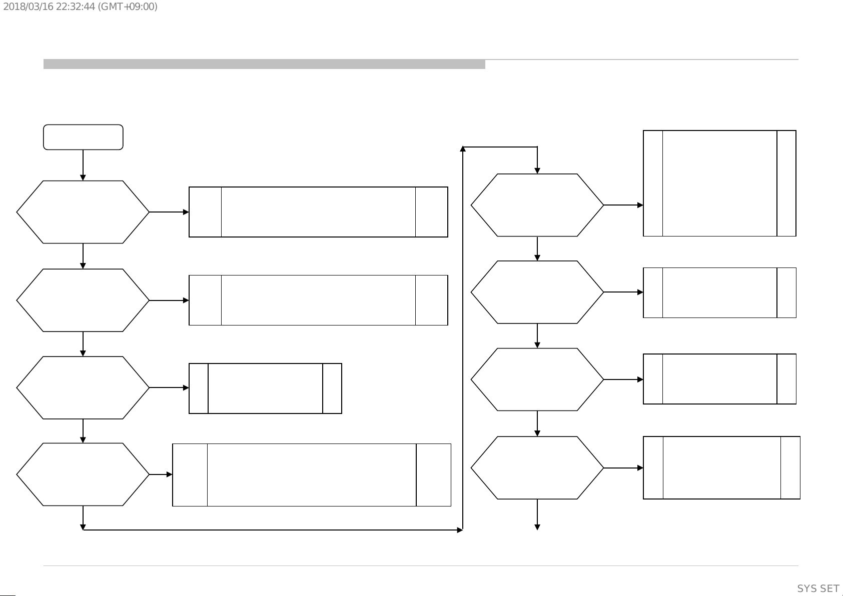
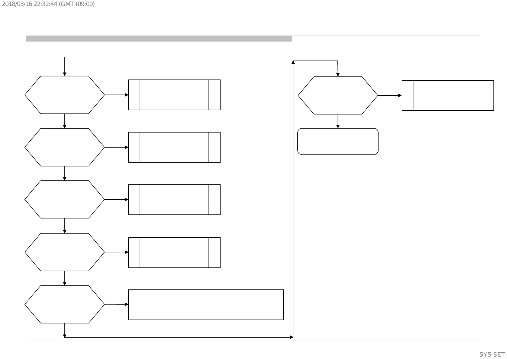
4.4 NO PICTURE: @ TUNER
RF input no picture / noisy
picture
Check RF source cable
and antenna, OK?
OK
Check Tuner power line:
3.3V at JL2800 = 3.3V?
1.8V at JL2801 = 1.8V?
*1
RESET value at JL2807 = 3.3V? *1
OK
All broadcasting channel
cannot be received?
OK
Refer to next page
NG
NG
Change RF cable and antenna
NG
Please refer DDCON
troubleshooting
Check part mounting condition
for I2C SDA & SCL line. (Refer Note I2C)
OK
NG
Change NG parts
connected to I2C bus
Notes: I2C
I2C line for all tuners except Japan
- Parts for I2C SDA line: R2800, C2803.
- Parts for I2C SCL line : R2801, C2804.
I2C line for Japan
- Parts for I2C SDA line: R2804
- Parts for I2C SCL line : R2805
*1 It does not use 1.8V and RESET in the UC model
47
SYSSET
Page 48

2018/03/1622:32:44(GMT+09:00)
4.4 NO PICTURE: @ TUNER
From Previous page
Digital
Analog
Refer Analog Tuning
Terrestrial/Cable
Refer Digital Tuning 1
For TW, NA-ATSC(MX/UC),
and LA-ISDB-T
Satellite
Check Tuner power line
12V at JL2822 = 12V?
OK
For AEP, JP, PA_T2, CH/HK,
and LA-T2(COL)
Refer Digital Tuning 2
NG
12V LNB Voltage
Checking
48
SYSSET
Page 49

2018/03/1622:32:44(GMT+09:00)
4.4 NO PICTURE: @ TUNER (BM2A)
BM2A (Top View)
For Tuner Power Lines
1.8V
12V
BM2A Tuner potion(Top View)
For Tuner Power Lines
3.3V
JL2822 = 12V
JL2800 = 3.3V
JL2807 = RESET:3.3V
JL2801 = 1.8V
BM2A Tuner potion(Bottom View)
For Tuner Power Lines
49
SYSSET
Page 50

2018/03/1622:32:44(GMT+09:00)
4.4 NO PICTURE: @ TUNER (BM2A)
BM2A (Top View)
For Tuner I2C line
R2801
C2803
C2804
R2800
R2805
R2804
50
SYSSET
Page 51

2018/03/1622:32:44(GMT+09:00)
4.4 NO PICTURE: @ TUNER
FOR 12V LNB Voltage Checking : @ AEP and JP
+12V_LNB Voltage Checking
Check fuse F2801
NG
Change the fuse
OK
Check LNB power line
+12V_MAIN at R495 = 12V?
NG
Check +12V_Main at CN400
(JL401/JL411)
NG
Check harness between
B-Board and G-board
OK
NG
OK
Check P_ON_HL signal line
at CL414(R451) = 3.3V?
NG
Please confirm Power
Sequence u-com
Harness broken
OK
MOSFET
Q408/Q409
broken
OK
Please refer G-board
troubleshooting
51
SYSSET
Page 52

2018/03/1622:32:44(GMT+09:00)
4.4 NO PICTURE: @ TUNER (BM2A)
BM2A (Top View)
12V LNB V oltage line
R451
CL414
+12V_LNB
F2801
R495
Q409
+12V_MAIN
Q408
52
SYSSET
Page 53

2018/03/1622:32:44(GMT+09:00)
4.4 NO PICTURE: @ TUNER
FOR ANALOG TUNING: @ All destination except JP
For LA-ISDB(BR/AR), LA-T2(COL) and TW only
Analog Tuning
For Other destination
Can it preset broadcast?
Confirm ANT or Cable connection
OK
OK
NG
NG
Notes:
- Parts for IFOUT_N line : FB2801, C2807, C2826
- Parts for IFOUT_P line : FB2802, C2808, C2825
- Parts for IFAGC line : R2809,R2838, C2827
: Insert correct signal in correct terminal.
A
A
Check IC1000 (SoC)
Check part mounting condition
for analog control line
“IFOUT_N, IFOUT_P, IFAGC”
NG
Change NG parts
OK
Check IC1000 (SoC) &
Tuner module
53
SYSSET
Page 54

2018/03/1622:32:44(GMT+09:00)
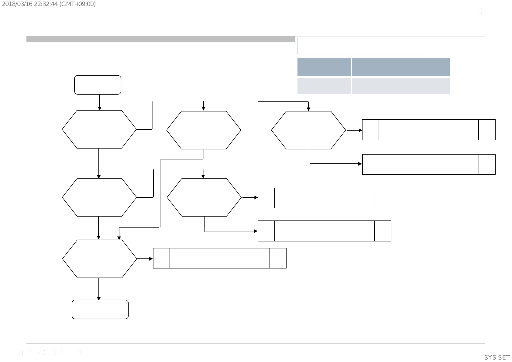
4.4 NO PICTURE: @ TUNER
FOR DIGITAL TUNING 1: @ TW, NA-ATSC(MX/UC), and LA-ISDB-T.
For TW/LA-ISDB-T
LA-T2(COL: Cable)
Confirm ANT or Cable connection
Digital Tuning 1
For NA-ATSC(MX/UC)
NG
A
Sound is normal?
No sound
OK
Notes:
- Parts for IFOUT_N line : FB2801, C2807, C2826
- Parts for IFOUT_P line : FB2802, C2808, C2825
- Parts for IFAGC line : R2809,R2838, C2827
A
: Insert correct signal in correct terminal.
Check IC1000 (SoC)
Check part mounting condition
for digital data line
“IFOUT_N, IFOUT_P, IFAGC”
NG
Change NG parts
OK
Check SoC(IC1000) and Tuner module
Check Tuner module
(Supplementary
information)
54
SYSSET
Page 55

2018/03/1622:32:44(GMT+09:00)
4.4 NO PICTURE: @ TUNER (BM2A)
BM2A (Top View)
IF & IFAGC line
R2838
C2827
FB2801
FB2802
C2808
C2807
R2809
C2825
C2826
(Supplementary
information)
55
SYSSET
Page 56

2018/03/1622:32:44(GMT+09:00)
4.4 NO PICTURE: @ TUNER
FOR DIGITAL TUNIN G 2: @ AEP, JP, PA_ T2, CH /HK , and LA -T2(COL)
Digital Tuning 2
LA-T2(COL)
CH/HK
NG
Confirm ANT or Cable connection Confirm ANT or Satellite connection
OK
Digital cable/ Terrestrial
Cable
Refer to Digital Tuning 1
A A
Terrestrial
OK
Sound is normal?
No sound
NG
Can it preset broadcast?
OK
For AEP/JP For PA_T2 and
OK
Check IC1000 (SoC)
Check part mounting condition
for I2C SDA & SCL line. (Refer Note I2C)
OK
NG
NG
Change NG parts connected to I2C bus
Notes: I2C
I2C line for all tuners except Japan
- Parts for I2C SDA line: R2800, C2803.
- Parts for I2C SCL line : R2801, C2804.
I2C line for Japan
- Parts for I2C SDA line: R2804
- Parts for I2C SCL line : R2805
Check part mounting condition for digital data line
“TU1_TS_DATA0, TU1_TS_CLK,
TU1_TS_VALID, TU1_TS_SYNC”
(Refer Notes)
NG
Change NG parts
OK
Change Tuner module
Check IC1000 (SoC) &
Confirm an insertion state of the
connector
Notes: TS line
-TS line parts for LA-T2/PA-T2/CH/HK :
R2868/R2869/R2870/R2871/RB2802
- TS line parts for AEP/JP :
R2814/R2815/R2816/R2817/RB2802
:Insert correct signal in correct terminal.
A
56
SYSSET
Page 57

2018/03/1622:32:44(GMT+09:00)
4.4 NO PICTURE: @ TUNER (BM2A)
BM2A (Top View)
TS1 line
RB2802
(Under the heatsink)
R2869
R2870
R2871
R2814
R2868
R2815
R2816
R2817
(Supplementary
information)
57
SYSSET
Page 58

2018/03/1622:32:44(GMT+09:00)
4.5 NO PICTURE: HDMI 1
No Picture
Check HDMI cable
OK
Check other
HDMI input
All Inputs NG
Check Picture by other TV set
which is same model
Target board & other
TV set both NG
Is using HDMI splitter ?
NO
Check Source equipment
by Reference TV set
(For example, RB1)
NG
Other TV set
OK
YES
Reference TV Set
OK
Change HDMI cable
Other Input is OK
IC1000 NG
Connect Sourc e
equipment directly
Change B-Board.
And inform the d esigner of i t
+5V line NG
Spec:4.7~5.3V
Replace R3646
Check the below point at
Connector side
・Check +5V line CL3642
・Check HPD line CL3629
・Check DDC lines CL3616/CL3617
・Check TMDS lines
+5V line OK
and HPD line NG
Spec:2.4~5.3V
Replace
R3627,R3634,R3639,
R3643,Q3602
NG
DDC lines NG
IC1000 NG
And inform the desi gner of it
All lines NG
RB3619,RB3620,
Replace
RB3603,R3664,R3665
NG
Replace
CN3603
NG
TMDS lines NG
Replace
RB3611,RB3612
NG
Reference TV set
NG
Check the settings o f
Source equipment,cable
58
SYSSET
Page 59

2018/03/1622:32:44(GMT+09:00)
4.5 NO PICTURE: HDMI 2
No Picture
Check HDMI cable
OK
Check other
HDMI input
All Inputs NG
Check Picture by other TV set
which is same model
Target board & other TV
set both NG
Is using HDMI splitter ?
NO
Check Source equipment
by Reference TV set
(For example, RB1)
NG
Other TV set
OK
YES
Reference TV Set
OK
Change HDMI cable
Other Input is OK
IC1000 NG
Connect Sourc e
equipment directly
Change B-Board.
And inform the d esigner of i t
+5V line NG
Spec:4.7~5.3V
Replace R3647
Check the below point at
Connector side
・Check +5V line CL3643
・Check HPD line CL3624
・Check DDC lines CL3610/CL3611
・Check TMDS lines
+5V line OK
and HPD line NG
Spec:2.4~5.3V
Replace
R3619
NG
DDC lines NG
IC1000 NG
And inform the desi gner of it
All lines NG
RB3613,RB3614,
RB3605,RB3606
Replace
RB3604,R3658,R3659
NG
Replace
CN3600
NG
TMDS lines NG
Replace
NG
Reference TV set
NG
Check the settings o f
Source equipment,cable
59
SYSSET
Page 60

2018/03/1622:32:44(GMT+09:00)
4.5 NO PICTURE: HDMI 3
No Picture
Check HDMI cable
OK
Check other
HDMI input
All Inputs NG
Check Picture by other TV set
which is same model
Target board & other TV
set both NG
Is using HDMI splitter ?
NO
Check Source equipment
by Reference TV set
(For example, RB1)
NG
Other TV set
OK
YES
Reference TV Set
OK
Change HDMI cable
Other Input is OK
IC1000 NG
Connect Sourc e
equipment directly
Change B-Board.
And inform the d esigner of i t
+5V line NG
Spec:4.7~5.3V
Replace R3644
Check the below point at
Connector side
・Check +5V line CL3644
・Check HPD line CL3627
・Check DDC lines CL3612/CL3613
・Check TMDS lines
+5V line OK
and HPD line NG
Spec:2.4~5.3V
Replace
R3627,R3634,R3639,
R3643,Q3602
NG
IC1000 NG
And inform the desi gner of it
DDC lines NG
Replace
RB3601,R3660,R3661
NG
All lines NG
Replace
CN3601
NG
TMDS lines NG
Replace
RB3615,RB3616,
RB3607,RB3608
NG
Reference TV set
NG
Check the settings o f
Source equipment,cable
60
SYSSET
Page 61

2018/03/1622:32:44(GMT+09:00)
4.5 NO PICTURE: HDMI 4
No Picture
Check HDMIcable
OK
Check other
HDMI input
All Inputs NG
Check Picture by other TV set
which is same model
Target board & other TV
set both NG
Is using HDMI splitter ?
NO
Check Source equipment
by Reference TV set
(For example, RB1)
NG
Other TV set
OK
YES
Reference TV Set
OK
Change HDMIcable
Other Input is OK
IC1000 NG
Connect Sourc e
equipment directly
Change B-Board.
And inform the d esigner of i t
+5V line NG
Spec:4.7~5.3V
Replace R3645
Check the below point at
Connector side
・Check +5V line CL3645
・Check HPD line CL3628
・Check DDC lines CL3614/CL3615
・Check TMDS lines
+5V line OK
and HPD line NG
Spec:2.4~5.3V
Replace
R3626,R3633,R3638,
R3642,Q3601
NG
DDC lines NG
IC1000 NG
And inform the desi gner of it
All lines NG
RB3617,RB3618,
RB3609,RB3610
Replace
RB3602,R3662,R3663
NG
Replace
CN3602
NG
TMDS lines NG
Replace
NG
Reference TV set
NG
Check the settings o f
Source equipment,cable
61
SYSSET
Page 62

2018/03/1622:32:44(GMT+09:00)
5.0 Key Switch Buttons Error
Side key buttons error
Check harness
connection between
B-board and switch
module
NG
Change harness
between B-board to
switch module harness
NG
Change switch module
NG
Main device issue
Change B-board
OK
OK
OK
Harness connection issue
B-board to switch module
harness issue
Switch module issue
62
SYSSET
Page 63

2018/03/1622:32:44(GMT+09:00)
5.1 IR Remote Commander Error
IR remote commander
does not respond
Check harness
connection between
B-board and Smart
Core
NG
Change harness
between B-board to
Smart Core harness
NG
Change Smart Core
NG
Change B-board
Main device issue
OK
OK
OK
Harness connection
issue
B-board to Smart Core harness
issue
Smart Core issue
63
SYSSET
Page 64

2018/03/1622:32:44(GMT+09:00)
5.2 Light Sensor Error
Backlight level does not
change when ambient
light changed
Check UI setting and
make sure light sensor
setting is “ON”
Setting is “OFF”
Setting issue
Change setting to “ON”
Setting is “ON”
Check harness
connection between
B-board and Smart
Core
NG
Change harness
between B-board to
Smart Core harness
NG
Change Smart Core
NG
Change B-board
Main device issue
OK
OK
OK
Harness connection
issue
B-board to Smart Core harness
issue
Smart Core issue
64
SYSSET
Page 65

2018/03/1622:32:44(GMT+09:00)
6.0 Network Malfunction: Ethernet (Wired)
[Network Set-up]
>[Wired Set-up]
on the TV
Connection Results
Cable Connection
Failed
Check cable
NG
Ethernet Cable
B Board
Power
+1.05V_M2_ST_ET
OK
OK
OK
B board
Power
Q3401 FET=ON
Connection Results
Local Access
Failed
Wired Set-up
IP address setting
Manual
Check IP address
&
Local router setting
OK
Check Ethernet
Connector pins
Soldering
J3400
OK
Auto
OK
Check
Local router
DHCP server
Check
Pulse Transformer
soldering
T3400,T3401
Connection Results
Internet Access
Failed
Proxy setting
OK
Check CMF
Soldering
L3400
OK
B board
OK
IC1000 issue
Change
B-board
NG
Change IC605
NG
Change Q304
NG NG
Change
Ethernet Connector
NG
Change Pulse Trans
Change CMF
65
SYSSET
Page 66

2018/03/1622:32:44(GMT+09:00)
6.2 Wireless Network malfunction (1/2)
1) Internal Wireless Network malfunction
Wireless Network
on the TV
Error message or no sc an res ul t
appear in the network setting?
Yes
*1
Hardware defect suspected.
Go to the next page
No
Is the Wi-Fi radio
strength too weak
or even No signal?
Yes
Check with another
Wi-Fi/BT module
OK
Wi-Fi/BT module
No
Bxx Board
NG
Access Point
66
SYSSET
Page 67

2018/03/1622:32:44(GMT+09:00)
Wireless Network malfunction (2/2)
*1
From previous page
Check harness
connection is OK
between Wi-Fi/BT
module and Bxx
OK
Check with
another Wi-Fi/BT
module
OK
Wi-Fi/BT module
NG
NG
NG
Connect properly
OK
Loose harness
Change harness
between Bxx board
and Wi-Fi/BT module
OK
Main Harness
NG
Change Bxx board
If Wi-Fi malfunction happens,
• Wi-Fi/BT module
• Harness betw een Wi-Fi/BT and Bxx
• Bxx board
are suspected.
67
SYSSET
Page 68

2018/03/1622:32:44(GMT+09:00)
6.3 Bluetooth malfunction
Voice Remote doesn’t work
Bluetooth Mouse/Keyboard/Controller doesn’t work
Bluetooth Speaker/Headphone/ doesn’t work
Home > Settings >
Bluetooth Settings
NG
else
Or
Or
OK
Can read
Near discoverable
Bluetooth Device
Check BT antenna
Connection is OK
OK
NG
Please refer
Voice Remote manual
Or
Bluetooth Mouse/Keyboard/Controller
Or
Bluetooth Speaker/Headphone operation manual
Check harness
connection is OK between
Wi-Fi/BT module and Bxx
OK
Change
Wi-Fi//BT module
OK
Wi-Fi/BT module
NG
Connect properly
NG
NG
TV Business Division
NG
Connect properly
Change harness
Between Bxx board
and Wi-Fi/BT module
OK
Main Harness
OK
NG
OK
Loose harness
Change Bxx board
Loose BT antenna
connection
68
68
SYSSET
Page 69

2018/03/1622:32:44(GMT+09:00)
When finished the operation of ser vice mode , please AC Plug OFF/ON the TV set
*If you don’t do AC plug OFF/ON, remain the Service Mode App and user can see the Service Mode after RC ON.
4.1 How to Enter Service Mode
From Standby Mode
1. Go to TV standby condition by remote commander.
2. Press “Display or i+ (info)”, “5”, “V olume+ ” then “TV power” on r emote.
3. You can see Serv ic e menu on display.
4
2
1
Service Mode
Model Information
Self diagnosis History
Video / Audio
Panel / PQ
General Setting
Tuner
Wi-Fi / BT
SECTION 4
SERVICE A DJUSTMENT
>>
>>
>>
>>
>>
>>
>>
>> SDB Service Menu
3
Summary of Service Control
Function The flow of control
Service mode on <Display or i+(info)> <5> <Vol. Up> <Power>
Close Service menu <Home>
Service mode off AC plug OFF
Item up / down
Item select left/right
Execute <Enter>
[Home]Exit
<↑> / <↓>
<←> / <→>
69
SYSSET
Page 70

2018/03/1622:32:44(GMT+09:00)
4.2 Software Version
1) In Service Mode, select “Model Information”, press “Enter” or → button to enter Status Information
Service Mode
Model Information
Self diagnosis History
Video / Audio
Panel / PQ
General Setting
Tuner
Wi-Fi / BT
>>
>>
>>
>>
>>
>>
>>
>> SDB Service Menu
[</>] Set [Home]Exit
Model
Status Information
Model Information
Model Number Setting
SERIAL NUMBER EDIT
>>
>>
>>
[</>] Set [Home]Exit
Main Micro
SW Version:
NVM Version:
Boot Version:
PQ Version:
AQ Version:
<ex>
exFRC:
CameraVID:
CameraPIC:
CameraFW:
<4k BE>
MLFW:
MAFW:
ADSP:
NDAT:
PDAT:
BDAT:
BCM:
FDAT:
UDAT:
BDIX:
PKG1.1.0.03.26.1.00.0
0043 CEI
V1.00000000
02000001
AQ2.5030
00.00.00.00
0
0
0
SF0.114
SF2.550
SF0.201
SD2.550
SP2.550
SD2.550
SF------SD0.001
SD0.000
SD2.550
2) Press “Enter” or “BACK” button t o r etur n to Ser vice Mode
Service Mode
Model Information
Self diagnosis History
Video / Audio
Panel / PQ
General Setting
Tuner
Wi-Fi / BT
>>
>>
>>
>>
>>
>>
>>
>> SDB Service Menu
[</>] Set [Home]Exit
70
SYSSET
Page 71

2018/03/1622:32:44(GMT+09:00)
4.3 Serial Number Edit (1)
1) In “Service Mode”, select “Model Information” by
pressing “↑” or “↓” then pressing “Enter” or “→”
button to enter inside.
2) Select “Serial Number Edit” by pressing “↑” or “↓”
button then pressing “→” button
3) Press “↑” or “↓” to input numbers
4) After user input data , press <Enter>
Model Information
Self diagnosis History
Video / Audio
Panel / PQ
General Setting
Tuner
Wi-Fi / BT
Service Mode
>>
>>
>>
>>
>>
>>
>>
>> SDB Service Menu
[</>] Set [Home]Exit
Pop-up dialog appear to confirm input data
correct
Serial Number can be set ONLY ONCE
5) Press “→” or “←” button to select YES
or NO. Select YES if input data is
correct. Select NO if input data is
incorrect. Press <Enter> to save
answer.
Model
Status Information
Model Information
Model Number Setting
Serial Number Edit
Model
Status Information
Model Information
Model Number Setting
Serial Number Edit 9 9 9 9 9 9 9
_ _ _ _ _ _ _
>>
>>
>>
[</>] Set [Home]Exit
>>
>>
>>
Input Data correct?
Yes
No
[</>] Set [Home]Exit
* The font color of Y ES/NO is change to black whe n it is selected.
71
SYSSET
Page 72

2018/03/1622:32:44(GMT+09:00)
4.3 Serial Number Edit (2)
If YES is selected, the input data is saved into EEPROM.
SERIAL NUMBER EDIT is grayed out and the serial
number that has been input is displayed. Operator will
not able to edit anymore.
If NO is selected, the input data is not saved into
EEPROM. The serial number that has been input is
displayed. Operator can still edit the Serial Number.
Model
Status Information
Model Information
Model Number Setting
Serial Number Edit 9999999
>>
>>
>>
[</>] Set [Home]Exit
Model
Status Information
Model Information
Model Number Setting
Serial Number Edit 9 9 9 9 9 9 9
>>
>>
>>
Input Data correct?
Yes
*The font color of Y ES/NO is change to black
when it is selected.
No
[</>] Set [Home]Exit
72
SYSSET
Page 73

2018/03/1622:32:44(GMT+09:00)
4.4 Model Number Setting
1) In “Service Mode”, select “M odel Information” by
pressing “↑” or “↓” then pressing “Enter” or “→”
button to enter inside.
2) Select “Model Number Setting” by pressing “↑” or
“↓” button then pressing “Enter” or “→” button
3) Press “↑” or “↓” arrow key to scroll Product Name
Candidate. (e.g. KD-65XF9005 CEI)
4) Select one Product Name from the list . After that
select “[OK]” and press “Enter” button.
Service Mode
Model Information
Self diagnosis History
Video / Audio
Panel / PQ
General Setting
Tuner
Wi-Fi / BT
>>
>>
>>
>>
>>
>>
>>
>> SDB Service Menu
[</>] Set [Home]Exit
Model
Status Information
Model Information
Model Number Setting
SERIAL NUMBER EDIT
>>
>>
>>
[</>] Set [Home]Exit
[MODEL_NUMBER_SETTING]
_ _ _ _ _ _ _ _ _ _ _ _
OK
73
SYSSET
Page 74

2018/03/1622:32:44(GMT+09:00)
4.5 WB Adjustment (If necessary)
1. In “Panel/PQ” service mode
a. Go to “WB Adjustment” category by “↑” or “↓”.
b. To select “WB Adjustment”, press → button.
c. To change data , press “←” or “→” on remote commander.
a.
Model Information
Self diagnosis History
Video / Audio
Panel / PQ
Tuner
Wi-Fi / BT
SDB Service Menu
Service Mode
>>
>>
>>
>>
>> General Setting
>>
>>
>>
b.
Panel / PQ
Back
WB Adjustment
WB/Mura/CUC data transfer
<<
>>
>>
[</>] Set [Home]Exit
c.
Back
R WB Gain
<<
<[ 0 ]>
<[ 0 ]> G WB Gain
<[ 0 ]> B WB Gain
<[ 0 ]> R WB Offset
<[ 0 ]> G WB Offset
<[ 0 ]> B WB Offset
[</>] Set [Home]Exit
[</>] Set [Home]Exit
74
SYSSET
Page 75

2018/03/1622:32:44(GMT+09:00)
4.6 WB data transfer
1. In “Panel/PQ” service mode
a. Go to “WB/Mura/CUC data transfer” category by “↑” or “↓”.
b. To select “WB/Mura/ CU C dat a tran sf er” , press → button.
c. To change data , press “←” or “→” on remote commander.
Please apply Main board or panel is replaced.
Back
<<
<[ 0.Soc to T-con ]>
<[ 0.Soc to T-con ]>
<[ 0.Soc to T-con ]>
[</>] Set [Home]Exit
Disuse in CR model
2. In “WB/Mura/C U C dat a tr ansf er ”
a. Select “WB/Gamma data transfer” by pressing “↑” or
“↓” on remote commander .
b. To change the items, press “←” or “→” on remote
commander and press “Enter” button.
Selectable items are:
0. SoC to T-con
1. T-con to SoC
2. No action
c. “Mura data transfer” and “ CUC data transfer” are also
displayed on t he menu, but Mura and CUC function
do not work on CR model. Please skip these items by
pressing “↓” on remote commander .
d. Select “[start]” and press “Enter” button to start
transfer.
75
SYSSET
Page 76

2018/03/1622:32:44(GMT+09:00)
4.7 HDD Performance Check (EU only)
1) In “Service Mode”, select
“General Setting” by pressing
“↑” or “↓” then pressing “Enter”
or “→” button to enter inside.
2) Select “HDD Performance
check ” by pressing “↑” or “↓”
then pressing “Enter” or “→”
button to enter inside.
3) A message "Pleas e w ait ..." is
displayed during performance
check processing.
4) Result OK or NG will be
displayed after performance of
HDD is checked
Service Mode
Model Information
Self diagnosis History
Video / Audio
Panel / PQ
General Setting
Tuner
Wi-Fi / BT
SDB Service Menu
HDD Performance Check
Please wait…
>>
>>
>>
>>
>>
>>
>>
>>
[</>] Set [Home]Exit
General Setting
Back
Aging mode
Ship Confirm
HDD Performance Ch
Update CI+ Credent
ECS_Enable
SCART RGB VREF
HDD Performance Check
Result
Back
<<
<[ Off ]>
>>
>>
>> AAA
>>
<[ Off ]>
<[ Auto ]>
[</>] Set [Home]Exit
<[ ]>
<[ NG ]>
<<
[</>] Set [Home]Exit
[</>] Set [Home]Exit
76
SYSSET
Page 77

2018/03/1622:32:44(GMT+09:00)
4.8 HDD Re-Register (EU only)
1) In “Service Mode”, select “General
Setting” by pressing “↑” or “↓” then
pressing “Enter” or “→” button to enter
inside.
2) Select “AAA” by pressing “↑” or “↓” then
pressing “Enter” or “→” button to enter
inside.
3) Result OK or NG will be displayed after
HDD re-registration is succeed/failed
Service Mode
Model Information
Self diagnosis History
Video / Audio
Panel / PQ
General Setting
Tuner
Wi-Fi / BT
SDB Service Menu
>>
>>
>>
>>
>>
>>
>>
>>
[</>] Set [Home]Exit
HDD Re-Register
Result
Back
Back
Aging mode
Ship Confirm
HDD Performance Ch
AAA
Update CI+ Credent
ECS_Enable
SCART RGB VREF
<[ NG ]>
<<
General Setting
<<
<[ Off ]>
>>
>>
>>
>>
<[ Off ]>
<[ Auto ]>
[</>] Set [Home]Exit
[</>] Set [Home]Exit
77
SYSSET
Page 78

2018/03/1622:32:44(GMT+09:00)
USB Update
1:Download USB image and unzip file.
2: copy unzip file to USB memory root folder.
3: USB memory insert TV.
4-a:USB image is newer soft version.
Automatically show message and start update.
Pleas e follow direct ions.
System software update
Copying USB update file. Please wait…
Preparing for system software update. During the system software update, the TV will
automatically restart. Please do not remove the USB device until an update complete
message is dis pl a yed . The update may take up to 15 minutes to complete .
Updating…
*BR/CO/LA only
TV will reboot and enter STBY status.
Press "Power" key of remote comm an d er to turn on T V.
System software update
The system software update is complete .
Some user s ettings may have changed during the update.
Please remove the USB device and select ”OK” to exit
OK
46%
5: finished
4-b:USB image is not newer soft version.
Automatically show message.
Pleas e follow direct ions.
System software update
Your software is up to date
Please remove the USB device and select [OK] to exit
OK
5: finished
Caution:
Do not power off while the update
is in progress.
78
SYSSET
Page 79

2018/03/1622:32:44(GMT+09:00)
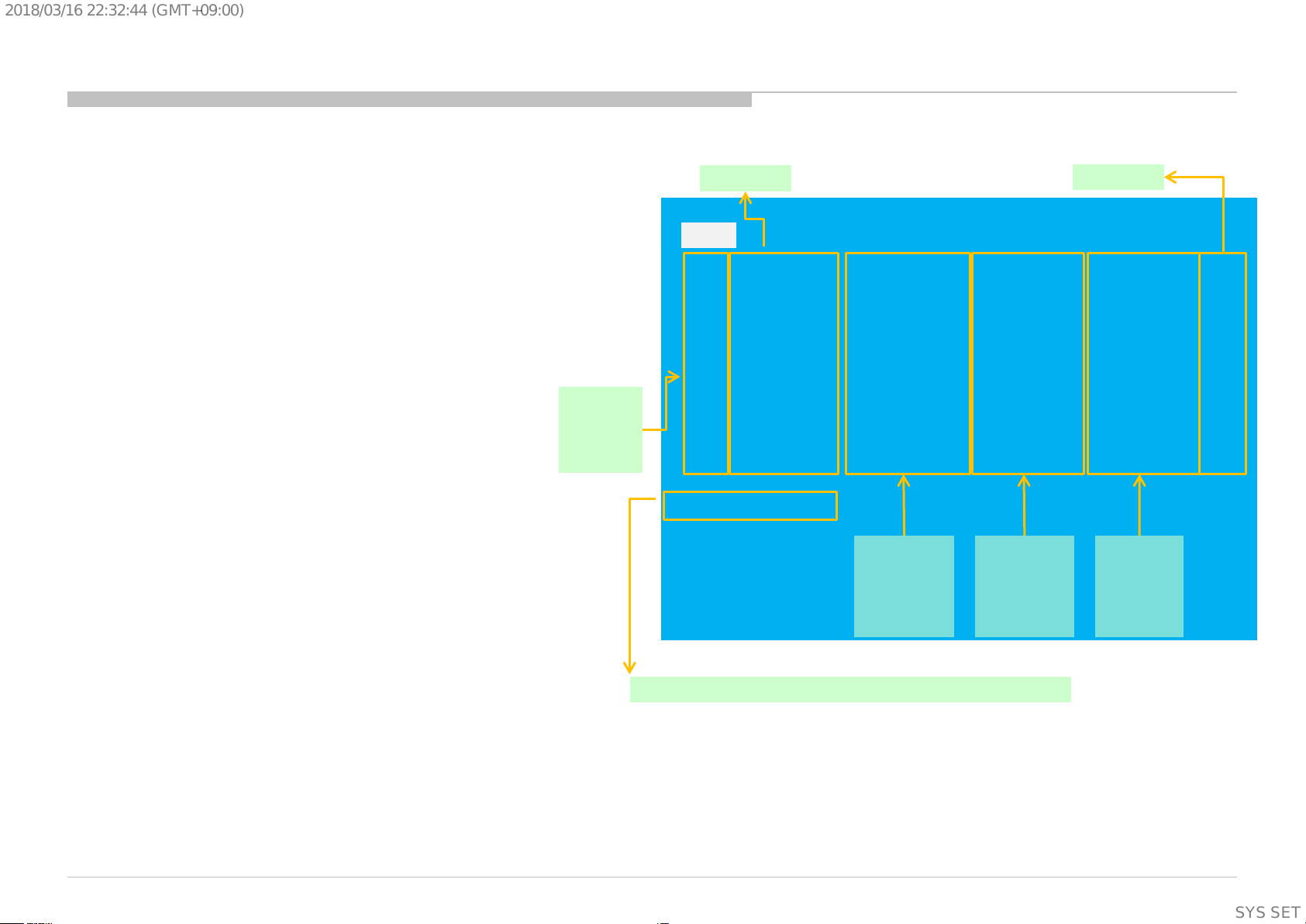
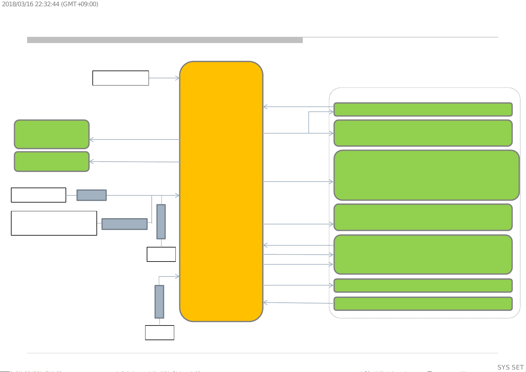
5.1 Block Diagram
* depend on destinations.
SECTION 5
DIAGRAMS
Video signal
Audio signal
Control Bus
RGBW LEDs
Light Sens.
IR Rx
Center Key
L/R Keys
* BCAS/CI
* RF
Composite
HDMI
USB3.0
USB2.0
* IR In
Ethernet
Optical
Out
CEC
S/PDIF
S/PDIF
Main
SoC
(IC1000)
eMMC
16GB
DDR3
4Gib x 5
BM2A board
Power Micro
(STM8S103F2U6)
Temp Sensor
(I2C)
DDCs
Vx1 8-lane (Video)
Vx1 4-lane (Graphics)
UART
I2C
I2S
DDR3
1Gib x 4
4K
BE
(IC4000)
I2C
I2S
Vx1 16-lane
4K/120p
D-Amp.
(TAS5760)
Panel
Tcon
EEPROM
(Panel ID)
Gx board
(PSU)
5-ch (2.1-ch)
Actuator
SP
+ WF
SP
SP
SP
Flash
HP/Line Out
* IR Blaster
* RS232C
IRB Micro
(S3F80P5X9R)
UART
UART
USB HS
WiFi/BT
(J20H088.00)
79
SYSSET
Page 80

CN203 CN5201 CN6
HUS_GND
1 15 #30
GND
1 51 GND
HUS_KEY_AD 2 12 #30
VBTX7P
2 50 RX7_P
HUS_POWER_KEY 3 14 #30
VBTX7N
3 49
RX7_N
1-474-647-11 1-821-900-11
GND
4 48 GND
JAM SZ15-03WLR JAM SZ15-03HGR
VBTX6P
5 47 RX6_P
VBTX6N
6 46 RX6_N
GND
7 45 GND
CN231
VBTX5P
8 44 RX5_P
7 1 WIFI_STBY_3.3V
VBTX5N
9 43 RX5_N
14 2 X_WIFI_BT_RST
GND
10 42 GND
1 3 SC_STBY_3.3V
VBTX4P
11
41
RX4_P
13 4 X_ WIFI_WAKEUP
VBTX4N
12 40 RX4_N
15 5
WIFI_GND
GND
13 39 GND
12 6 X_BT_WAKEUP
VBTX3P
14 38 RX3_P
9 7
WIFI_GND
VBTX3N
15 37 RX3_N
NC
8
3D_LR
GND
16
36 GND
8 9
WIFI_GND
VBTX2P
17 35 RX2_P
NC 10 X_BT_WAKE2
VBTX2N
18 34 RX2_N
4 11
WIFI_GND
GND
19 33
GND
2 12
KEY_AD
VBTX1P
20 32 RX1_P
2 13
5V_MAIN
VBTX1N
21 31 RX1_N
CN001
3 14
POWER_KEY
GND
22 30 GND
STBY3.3V
1 3 #30 1 15
WIFI_GND
VBTX0P
23 29 RX0_P
5V_MAIN 2 13 #30 11 16
SC_OPT_SENSE
VBTX0N
24 28 RX0_N
GND 3 17 #3 0 3 17
SC_GND
GND
25 27 GND
LED_AMBER 4 20 #30 12 18
SC_SIRCS
VBTXLOCKN0
26 26 LO CKN
LED_PWM_W 5 22
#30 10 19
SC_MAIN_3.3V
VBTXHTPDN0
27 25 HT PDN
LEY_STBY_PWM_R 6 28 #30 4 20
SC_LED_AMBER
GND
28 24 GND
LED_STBY_PWM_B 7
26 #30 9 21
SC_GND
GND(AGING_MOD E)
29 23 AGP1
LED_STBY_PWM_G 8 24 #30 5 22
SC_LED_PWM_W
NC
30 22 AGP0
GND 9 21 #3 0 NC 23
KEY_GND
NC/WP
31 21 n WP
MAIN_3.3V 10 19 #30 8 24
SC_LED_PWM_G
WP/EVD0_DET
32 20 E VDD_DET
OPT_SENSE 11 16 #30 NC 25
(TS_SCL)
SCL/SCL2
33 19 I2C-SCL2
SIRCS
12 18 #30 7 26
SC_LED_PWM_B
SDA/SDA2
34 18 I2C-SDA2
1-821-139-11 1-821-126-11 NC 27
TS_GND
3D_EN/PANEL_DET
35 17 NC /GND
JAM SYT10-12WS SYT10-12HG 6 28
SC_LED_PWM_R
3D_SYNC_IN/NC
36 16 Data format 0
NC 29
TS_TEMP(TS_SDA)
3D_SYNC_OUT/NC
37
15 Data format 1
NC
30
TS_MAIN_3.3V
GND/SCL1
38 14 I2C-SCL1
1-819-455-11 1-818-693-22
PANEL_DET/SDA1
39 13 I2C-SDA1
USB Cable
SHLDP-30V-S-1 (B) JST SM30B-SHLDS-GANF-1-TF(LF)(SN)
GND/ERROR DET
40 12 E RROR DETECTION
GND 15 5 #30
GND/AC_DET
41 11 A C_DET
RST_L 14 2
#30
GND/GB&OFF AS DONE
42 10 JB & OFF RS Done
WOW_L 13 4 #3 0
NC
43 9 NC
WOBT1_L 12 6 #30
NC/12V
44
8 NC
WOBT2_L 11 NC #30
CN230
NC/12V
45 7 NC
VSYNC 10 NC #30
USB
6 1
WIFI_STBY_3.3V (VBUS)
NC/12V
46 6 NC
GND 9 7 #30
USB
3 2
WIFI_USB_M (D-)
NC/12V
47 5
NC
GND
8
9 #30
USB
2
3
WIFI_USB_P (D+)
NC/12V
48 4 NC
VCC 7 1
#30
USB
NC
4
NC (ID)
NC/12V
49 3 NC
VCC 6
1 1 BLK#28
USB
5 5
WIFI_STBY_3.3V (GND)
NC/12V
50 2 NC
VCC 5
5 1 RED#28
USB
1 Shell
WIFI_GND
NC/12V
51 1 NC
GND
4 11 #30
1-844-049-11
DM 3 2 1 WHT#28 ACON u-USB Plug SMK CSS5305-6H02E JAE/FI-RE51S-HF
DP 2 3
1 GRN#28 FFC Direct Conne ctor :IPEX
GND 1 Shell 1 Shield
1-844-754-11
JAM STA12-15WH-ET (JAM) STA12-15HG
CN5200
CN10
NC/Emergency Update
1
41 Em ergency Update
NC
2
40 ON_ RF
NC/QSMEN
3
39
QSMEN
NC/Vx1 Byte Select
4
38 Vx1 Byte Select
SPI_CS
5
37
NC
SPI_CK
6
36 NC
SPI_EN_B
7
35
NC
NC
8
34 NC
NC
9
33 NC
NC
10
32 NC
NC
11
31 NC
VCA
12
30 NC
BUS_SW
13
29 NC
SPI_DI
14
28 NC
CN6601
SPI_DO
15
27 NC
1-842-551-11
CN6401
SPI_EN_A
16
26 NC
SJM20-28WLB/JAM
1-844-784-11
GND
17
25 GND
#22
15 28
EVDD_24V
JAM SJM20-20WLA
JAM SJM20-20HG
VBTX15P
18
24 RX15_P
#22
14 27 EVDD_24V
1-844-798-11
CN400
VBTX15N 19
23 RX15_N
#22
13 26
EVDD_24V
REG12V
20 8 #22 #22
13 20 GND GND 20
22 GND
#22
12 25 EVDD_24V
REG12V
19 7 #22 #22 16
19 POWER_AU VBTX14P 21
21 RX14_P
#22
11 24 EVDD_24V
REG12V
18 6 #22 #22 12
18 GND VBTX14N 22
20
RX14_N
#22
10 23 EVDD_24V
REG12V
17 5 #22 #22 15 17 POWER_AU
GND 23
19 GND
#22
9 22 EVDD_24V
REG12V
16 19 #22 #26 4 16 AC_OFF_DET VBTX13P 24
18 RX13_P
#22
8 21
EVDD_24V
REG12V
15 17 #22 #22 14 15 POWER_AU VBTX13N 25
17 RX13_N
20 NC
REG12V
14 15 #22 #26
2 14 BL_ERR GN D 26
16 GND
#22
7 19 EVDD_GND
GND
13 20 #22 #26 3
13 BL_ON/TCON_24_ON VBTX12P 27
15 RX12_P
#22
6 18 EVDD_GND
GND
12 18 #22
#26 1 12 TCON_ON/TCON_12_ON
VBTX12N 28
14 RX12_N
#22
5 17 EVDD_GND
GND
11 NC #26 5 11 POWER_ON GND 29
13 GND
#22
4 16
EVDD_GND
GND
10 4 #22 NC 10 NC VBTX11P 30
12 RX11_P
#22
3
15 EVDD_GND
GND
9 3 #22 #22 6 9 STBY_3.3V VBTX11N 31
11 RX11_N
#22
2 14 EVDD_GND
GND
8 2 #22 #22
20 8 REG_12V
GND 32
10 GND
#22
1 13 EVDD_GND
GND
7
1
#22 #22 19 7
REG_12V VBTX10P 33
9 RX10_P
NC 12 TCON_12V
STBY
6 9 #22 #22 18 6 REG_12V VBTX10N 34
8 RX10_N
NC 11 TCON_12V
POWER_ON
5 11 #26 #22 17 5 REG_12V GN D 35
7 GND
NC 10 TCON_12V
AC_OFF_DET
4 16 #26 #22 10 4 GND VBTX9P 36
6 RX9_P
#22
9 9 TCON_12V
TCON_24_ON
3 13 #26 #22
9 3 GN D
VBTX9N 37
5 RX9_N
#22
8 8 TCON_12V
BL_ERR
2 14 #26 #22 8
2 GND GND 38
4 GND
#22
7 7 TCON_12V
TCON_12_ON
1 12
#26 #22 7
1 GND VBTX8P
39
3
RX8_P
#22
6 6
TCON_GND 1-843-150-11 1-843-151-11
VBTX8N 40
2 RX8_N
#22
5 5 TCON_GND
SFP79-02WLB/JAM
PBDP-20V-S
JST SM20B-PBDSS-TF
GND 41
1 GND
#22
4 4 TCON_GND
CN6101
1-843-699-12, IPEX
#22
3 3 TCON_GND
1-822-908-11
or 1-844-642-11, Molex JAE/F I-RE41S-HF
NC 2 TCO N_GND
AC-N
1
HF507S-41-72
NC 1 TCO N_GND
AC-L
2
JAM SJM20-28HG CN5000
1-842-598-11
GND
1
N.C(OPEN)2N.C(OPEN)3LD_ERR_DET
4
SWF+
1
10
#22
N.C(OPEN)
5
SWF- 2
12
#22
N.C(OPEN)
6
JST SMP-02VF-N
N.C(OPEN)
7
1-784-991-21
N.C(OPEN)8N.C(OPEN)9TM_RDY_MON10N.C(OPEN)
11
EX2+ 1 1
#22
N.C(OPEN)
12
EX2-
2 2
#22 P_SENS_MON
13
EX1+
3 5
#22
CN3201 TM_DRV_EMIT
14
EX1- 4 6
#22
1 1 EXCITER2_LP
TM_SPI_SYNC
15
JST SMP-04V-NC
2 2
EXCITER2_LN
GND
16
1-560-346-21
2 3 EXCITER2_RN
N.C(OPEN)
17
1 4
EXCITER2_RP
N.C(OPEN)
18
3
5
EXCITER1_LP
N.C(OPEN)
19
4 6 EXCITER1_LN
N.C(OPEN)
20
EX2+ 1
4
#22
5 7 EXCITER1_RN
GND
21
EX2- 2
3
#22
4
8
EXCITER1_RP
TM_DRV_SPI_MOSI_00
22
NC 3
NC
NC
9
SWF_RP
TM_DRV_SPI_MISO_00
23
EX1+ 4 8
#22
1
10
SWF_RP
TM_DRV_SPI_SCK_00
24
EX1-
5 7
#22 NC
11 SWF_RN
TM_DRV_SPI_NSS_00
25
JST SMP-
05
V-BC
2 12 SWF_RN
GND
26
1-560-347-11 1-842-597-11
1-842-570-12
N.C(OPEN)
27
JAM PBVP12V-S
JST SM12B-PBVSS-TB(LF)(SN)
SA_MODE
28
N.C(OPEN)
29
BL_ON
30
1-843-858-71
CN11
NC
1 GN DNC2 GN D
#22
3 3 GND
#22
4
4 GN D
#22
5 5
GND
#22
6 6 GND
#22
7 7 VDD_12V
#22
8 8 VDD
#22
9 9 VDD
NC
10 VDDNC11 VDDNC12 VDDNC13 NCNC14 NC
Yeonho Yeonho
20022HS-14B2 20022WR – H14B2
1-844-572-21
CN5
#22
13 1 EVSS
#22
14 2 EVSS
#22
15 3 EVSS
#22
16 4 EVSS
#22
17 5 EVSS
#22
18 6 EVSS
#22
19
7 EVSS_ GND
#22
21 8 EVDD
#22
22 9 EVDD
#22
23 10
EVDD
#22
24 11 EVDD
#22
25 12 EVDD
#22
26 13 EVDD
#22
27 14 EVDD
#22
28 15 EVDD_24V
Yeonho Yeonho
20022HS-15B2(BK) 20022WR – H15B2(BK)
1-844-573-11
1-842-546-22, IPEX
or 1-844-527-11, Molex
Main Harness
FY17_Full_MVT_CR_MAIN
Wifi/BT
FY17
BM2A Board
Key(3M-P)
VXO-FFC
PL_MONIP_51P_01T
BT Antena
G812 Board
AC Inlet
51pin FFC
SP Harness
FY18_Full_MVT_CR_SP
HS7
SPEAKER WF
SPEAKER Main
Lch
SPEAKER Main
Rch
T-CON
board
41pin FFC
2018/03/1622:32:44(GMT+09:00)
5.2 Connector Diagram
80
SYSSET
Page 81

2018/03/1622:32:44(GMT+09:00)
Panel : Service Panel Unpacking
SECTION 6
PANEL and TV SET HANDLING
You can cut the red line and open in
order to make it easy to take
reinforcement out.
Put reinforcement on stable flat floor .
Open reinforcement and tear the AL
bag to take panel out .
You can tear it by hand easily
once you make smal l c ut on i t.
※ Please take car e not to c ut panel
when you make small cut on the bag.
※ Please take car e not to fall down
the panel.
81
SYSSET
Page 82

2018/03/1622:32:44(GMT+09:00)
Holding on Vertical Position & Moving
Don’t touch frame by finger. Don’t push display by finger .
Don’t push display by finger .
82
SYSSET
Page 83

2018/03/1622:32:44(GMT+09:00)
Holding on Vertical Position & Moving
Don’t catch these sheet metal parts by finger.
83
SYSSET
Page 84

2018/03/1622:32:44(GMT+09:00)
On Working Table
Caution
• Put soft & clean sheet on the table.
• Be careful to dust, scrap, screw on table.
(There are risks of scratches on screen surface.)
• One-man handling is prohibited.
84
SYSSET
Page 85

2018/03/1622:32:44(GMT+09:00)
Lifting Up (OK)
Hold top and bottom sides.
Holding positions are as follows.
Lift up to vertical positi on
like above picture.
Holding Positions
85
SYSSET
Page 86

2018/03/1622:32:44(GMT+09:00)
Lifting Up (NG)
NG
Don’t hold around corner.
Don’t hold left or right edges.
86
SYSSET
Page 87

2018/03/1622:32:44(GMT+09:00)
TV SET :
Caution
• Put soft & clean sheet on the table.
• Be careful to dust, scrap, screw on table.
(There are risks of scratches on screen surface.)
• One-man handling is prohibited.
On Working Table
OK
Soft & Clean Sheet (EPE/P E-FM/etc)
No-Dust/Scrap/Screw/etc
87
SYSSET
Page 88

2018/03/1622:32:44(GMT+09:00)
Lifting Up (OK)
OK
Holding Positions
Hold top and bottom sides.
Holding positions are as follows.
150mm
Top
Bottom
150mm
Lift up to vertical position
like above picture.
Holding Positions
88
SYSSET
Page 89

2018/03/1622:32:44(GMT+09:00)
Lifting Up (NG)
NG
Don’t hold around corner. Don’t hold left or right edges.
89
SYSSET
Page 90

2018/03/1622:32:44(GMT+09:00)
Holding on Vertical Position & Moving
OK
NG
Don’t catch frame by finger.
OK
NG
Don’t push display by finger.
NG
Don’t push display by finger.
90
SYSSET
Page 91

2018/03/1622:32:44(GMT+09:00)
Holding on Vertical Position & Moving
OK
OK
OK
NG
NG
Don’t hold antenna terminal.
91
SYSSET
Page 92

2018/03/1622:32:44(GMT+09:00)
9-888-748-01
Sony EMCS (Malaysia) Sdn. Bhd.
RDCM
English
© 2018.03
92
SYSSET
 Loading...