

Sony KD-28DX50U, KD-32DX50U Service Manual
- 1 -
SERVICE MANUAL
FE-2D
CHASSIS
MODEL
COMMANDER DEST CHASSIS NO.
KD-28DX50U
RM-933 UK SCC-Q52S-A
MODEL
COMMANDER DEST CHASSIS NO.
KD-32DX50U
RM-933 UK SCC-Q52T-A
KV-28/32DX50
RM-933

- 2 -
TABLE OF CONTENTS
Section Title Pa ge Section Title Pa ge
Caution .................... 3
Specifications .................... 4
Connectors .................... 5
Self Diagnostic Software .................... 6
1. GENERAL
Automatically Tuning the TV .................... 7
Switching between digital and
analogue mode .................... 7
Digital Te xt .................... 7
Analogue Text .................... 8
The Channel Index Menu .................... 8
The Digital EPG Menu .................... 9
The Info Menu .................... 9
The Main Menu .................... 10
Detail Set-up Menu .................... 10
Using the TV Menu System .................. 11
Manual Programme Preset Menu .............. 11
Connecting other Equipment .................... 12
Remote Control of Equipment .................... 12
Specifications .................... 13
Troubleshooting .................... 13
2. DISASSEMBLY
2-1. Rear Cover Removal .................... 14
2-2. Front Control Module Removal ................... 14
2-3. Chassis Removal and Refitting .................... 14
2-4. A Board Removal [Step 1] .................... 15
2-5. A Board Removal [Step 2] .................... 15
2-6. D3 Board Removal .................... 15
2-7. F3 Board Removal .................... 15
2-8. A1 Board Removal .................... 16
2-9. Service Position .................... 16
2-10. N Board Removal .................... 16
2-11. Picture Tube Removal .................... 17
Bottom Plates .................... 18
3. SET-UP ADJUSTMENTS
3-1. Beam Landing .................... 19
3-2. Convergence .................... 20
3-3. Focus Adjustment .................... 22
3-4. Screen (G2), White Balance .................... 22
4. CIRCUIT ADJUSTMENTS
4-1. Electrical Adjustments .................... 23
4-2. Test Mode 2 .................... 25
5. DIAGRAMS
5-1. Block Diagrams (1) .................... 26
Block Diagrams (2) .................... 27
Block Diagrams (3) .................... 28
5-2. Circuit Board Location .................... 29
5-3. Schematic Diagrams and
Printed Wiring Boards .................... 29
* A Board PWB .................... 31
* A Board Schematic .................... 32
* A1 Board PWB .................... 36
* A1 Board Schematic .................... 37
* F7 Board PWB .................... 39
* F7 Board Schematic .................... 38
* B1 Board PWB .................... 39
* B1 Board Schematic .................... 40
* D3 Board PWB .................... 39
* D3 Board Schematic .................... 38
* F3 Board PWB .................... 39
* F3 Board Schematic .................... 38
* H7 Board PWB .................... 39
* H7 Board Schematic .................... 38
* H4 Board PWB .................... 39
* H4 Board Schematic .................... 40
* C Board PWB .................... 42
* C Board Schematic .................... 41
* D2 Board PWB .................... 42
* D2 Board Schematic .................... 41
* VM Board PWB .................... 42
* VM Board Schematic.................... 43
5-4. Semiconductors .................... 44
5-5. IC Blocks .................... 45
6. EXPLODED VIEWS
6-1. Chassis .................... 46
6-2. Picture Tube .................... 47
7. ELECTRICAL PARTS LIST .................... 48
ATTENTION
APRES AVOIR DECONNECTE LE CAP DE’LANODE,
COURT-CIRCUITER L’ANODE DU TUBE CATHODIQUE ET
CELUI DE L’ANODE DU CAP AU CHASSIS METALLIQUE DE
L’APPAREIL, OU AU COUCHE DE CARBONE PEINTE SUR LE
TUBE CATHODIQUE OU AU BLINDAGE DU TUBE
CATHODIQUE.
ATTENTION !!
AFIN D’EVITER TOUT RISQUE D’ELECTROCUTION
PROVENANT D’UN CHÁSSIS SOUS TENTION, UN
TRANSFORMATEUR D’ISOLEMENT DOIT ETRE UTILISÈ LORS
DE TOUT DÈPANNAGE LE CHÁSSIS DE CE RÈCEPTEUR EST
DIRECTMENT RACCORDÈ Á L’ALIMENTATION SECTEUR.
ATTENTION AUX COMPOSANTS RELATIFS Á
LA SECURITÈ!!
LES COMPOSANTS IDENTIFIÈS PAR UNE TRAME ET PAR UNE
MARQUE
SUR LES SCHÈMAS DE PRINCIPE, LES VUES
EXPLOSÈES ET LES LISTES DE PIECES SONT D’UNE IMPORTANCE CRITIQUE POUR LA SÈCURITÈ DU FONCTIONNEMENT,
NE LES REMPLACER QUE PAR DES COMPSANTS SONY DONT
LE NUMÈRO DE PIÈCE EST INDIQUÈ DANS LE PRÈSENT
MANUEL OU DANS DES SUPPLÈMENTS PUBLIÈS PAR SONY.
CAUTION
SHORT CIRCUIT THE ANODE OF THE PICTURE TUBE AND THE
ANODE CAP TO THE METAL CHASSIS, CRT SHIELD, OR THE
CARBON PAINTED ON THE CRT, AFTER REMOVAL OF THE
ANODE CAP.
WARNING !!
AN ISOLATION TRANSFORMER SHOULD BE USED DURING
ANY SERVICE WORK TO AVOID POSSIBLE SHOCK HAZARD
DUE TO LIVE CHASSIS, THE CHASSIS OF THIS RECEIVER IS
DIRECTLY CONNECTED TO THE POWER LINE.
SAFETY-RELATED COMPONENT WARNING !!
COMPONENTS IDENTIFIED BY SHADING AND MARKED
ON
THE SCHEMATIC DIAGRAMS, EXPLODED VIEWS AND IN THE
PARTS LIST ARE CRITICAL FOR SAFE OPERATION. REPLACE
THESE COMPONENTS WITH SONY PARTS WHOSE PART
NUMBERS APPEAR AS SHOWN IN THIS MANUAL OR IN
SUPPLEMENTS PUBLISHED BY SONY.
- 3 -
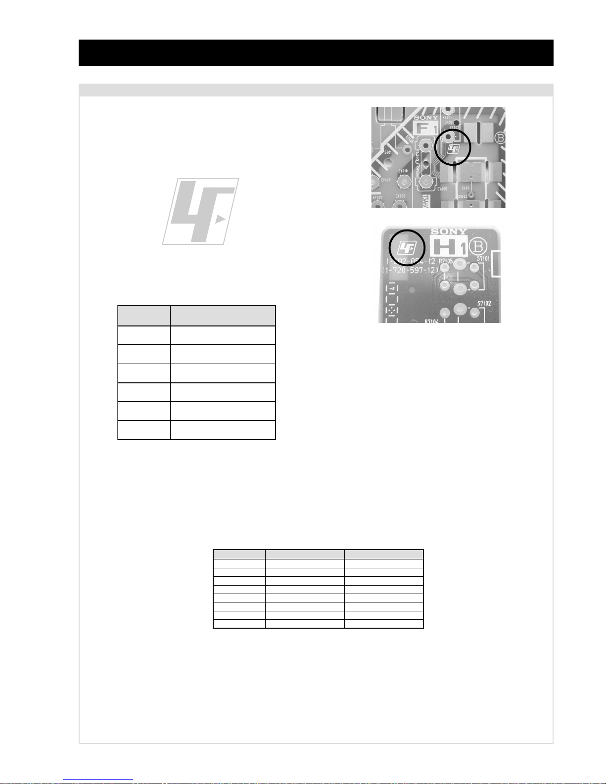
The circuit boards listed below [T able 1] used in these models may
have been processed using Lead Free Solder . The boards are
identified by the LF logo located close to the board designation e.g.
F1, H1 etc [ see examples ]. The servicing of these boards requires
special precautions to be taken as outlined below .
Table 1
CAUTION
Lead Free Soldered Boards
example 1
example 2
It is strongly recommended to use Lead Free Solder material in order to guarantee optimal quality of new solder joints. Lead Free Solder is
available under the following part numbers :
Due to the higher melting point of Lead Free Solder the soldering iron tip temperature needs to be set to 370 degrees centigrade. This requires
soldering equipment capable of accurate temperature control coupled with a good heat recovery characteristics.
For more information on the use of Lead Free Solder, please refer to http://www.sony-training.com
rebmuntraP retemaiD skrameR
91-500-046-7mm3.0gK52.0
02-500-046-7mm4.0gK05.0
12-500-046-7mm5.0gK05.0
22-500-046-7mm6.0gK52.0
32-500-046-7mm8.0gK00.1
42-500-046-7mm0.1gK00.1
52-500-046-7mm2.1gK00.1
62-500-046-7mm6.1gK00.1
draoB noitcnuF
1BgnihctiwSV,U,Y
CtuOB,G,R
2DnoitcelfeDedoMtramS
3DgnihctiwS3:4
3FesuF/tupnICA
MVPQD&sucoFcimanyD
- 4 -
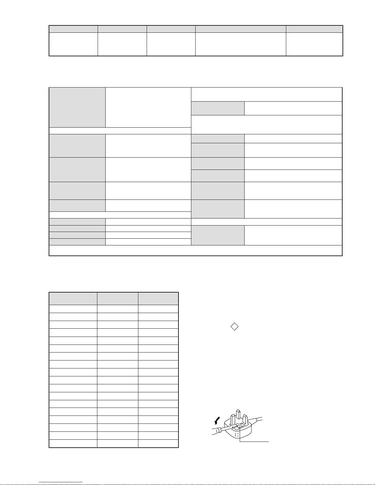
WARNING (UK Models only)
The flexible mains lead is supplied connected to a B.S. 1363 fused
plug having a fuse of 5 AMP rating. Should the fuse need to be
replaced, use a 5 AMP FUSE approved by ASTA to BS 1362, ie one
that carries the
ASA
T
mark.
IF THE PLUG SUPPLIED WITH THIS APPLIANCE IS NOT SUITABLE FOR THE OUTLET SOCKETS IN YOUR HOME, IT SHOULD
BE CUT OFF AND AN APPROPRIATE PLUG FITTED. THE PLUG
SEVERED FROM THE MAINS LEAD MUST BE DESTROYED AS A
PLUG WITH BARED WIRES IS DANGEROUS IF ENGAGED IN A
LIVE SOCKET.
When an alternative type of plug is used, it should be fitted with a
5 AMP FUSE, otherwise the circuit should be protected by a 5 AMP
FUSE at the distribution board.
How to replace the fuse.
Open the fuse compartment with
a screwdriver blade and replace
the fuse.
FUSE
emaNledoM
metI
U05XD82-VK U05XD23-VK
bmoClaPFFOFFO
PIPFFOFFO
ytiroirPBGRNONO
xoBrefooWFFOFFO
1tracSNONO
2tracSNONO
)3(nitnorFNONO
4tracSFFOFFO
rotcejorPFFOFFO
G/BmroNFFOFFO
ImroNNONO
K/DmroNFFOFFO
SUAmroNFFOFFO
LmroNFFOFFO
TASmroNFFOFFO
MmroNFFOFFO
txeteleTNONO
oeretSmaciNNONO
LEDOMMETI metsySnoisiveleT metsySoeretS egarevoClennahC metsySroloC
UT-BVD/IoeretSMACIN96B-12B:FHU
LAP
34.4CSTN,85.3CSTN
)NIOEDIV(
LM@PM2-GEPM
ebuTerutciP
nortinirTDFyalpsiDtalF
)sehcni82(mc17xorppA
derusaemerutcipmc66xorppA(
U05XD82-VK)yllanogaid
)sehcni23(mc28xorppA
derusaemerutcipmc67xorppA(
U05XD23-VK)yllanogaid
tuptuodnuoS
rekaepstfeLdnathgiR)SMR(W7x2)rewoPcisuM(W41x2
snoitacificepSlareneG
]RAER[slanimreTtuptuO/tupnI
rotcennocoruEnip-12:1
)dradnatsCELENEC(
.slangisoediVdnaoiduArofstupnI
.BGRrofstupnI
oiduAdnaoediVVTfostuptuO
.slangis
stnemeriuqeRrewoPV042-022
noitpmusnoCrewoP
)U05XD82-VK(W79
)U05XD23-VK(W79
rotcennocoruEnip-12:2
.slangisoediVdnaoiduArofstupnI
.oediVSrofstupnI
.slangisoiduAdnaoediVVTfostuptuO
)elbatceles(
snoisnemiD
)U05XD82-VK(mm365x175x887xorppA
)U05XD23-VK(mm295x026x688xorppA
thgieW
)U05XD82-VK(gk54xorppA
)U05XD23-VK(gk16xorppA
skcaJonohPoiduArofelbairavsrotcennoCtuptuO
slangiS
seirosseccAdeilppuS
)1(rednammoCetomeR339-MR
)2(yrettab6RdetangisedCEI
daeLFR
latigiD
kcaJmedoM
AICMCP
serutaeFrehtO
,kniltramS,FD&PQD,noitcudeResioNotuA
.ybloDlautriV,srenuTowT,GEHM
]TNORF[slanimreTtuptuO/tupnI
kcajenohpdaeHkcajinimoerets
lortnoCderarfnI:metsySlortnoCetomeR
stupnioiduAskcajonohp
stnemeriuqerrewoP
cdV3
noitangisedCEIseirettab2
)AAezis(6R
stupnioediVskcajonohp
tupnioediVSNIDnip4
.ecitontuohtiwegnahcottcejbuserasnoitacificepsdnangiseD
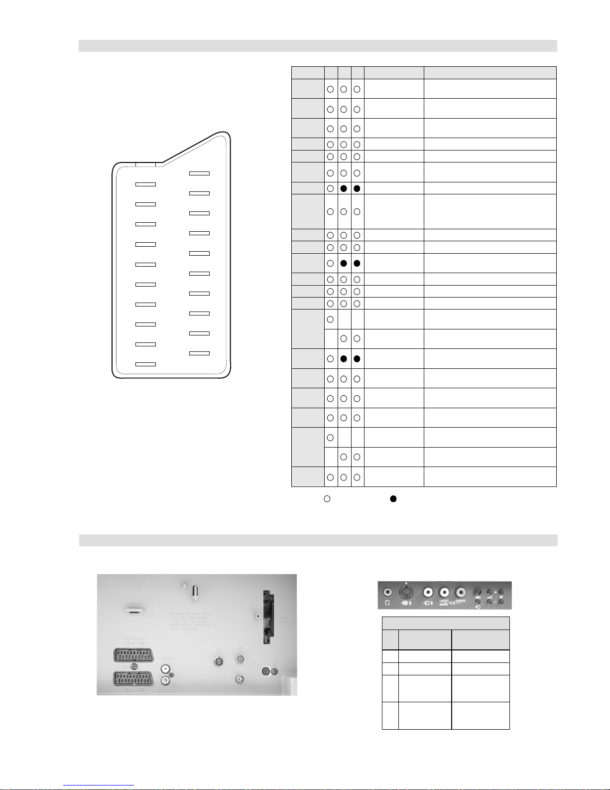
- 5 -
21 pin connector
Connected Not Connected (open) * at 20Hz - 20kHz
Pin No 1 2 4 Signal Signal level
1 Audio output B
(right)
Standard level : 0.5V rms
Output impedence : Less than 1kohm*
2
Audio output B
(right)
Standard level : 0.5V rms
Output impedence : More than 10kohm*
3
Audio output A
(left)
Standard level : 0.5V rms
Output impedence : Less than 1kohm*
4 Ground (audio)
5 Ground (blue)
6 Audio input A
(left)
Standard level : 0.5V rms
Output impedence : More than 10kohm*
7 Blue input 0.7 +/- 3dB, 75 ohms positive
8 Function select
(AV control)
High state (9.5-12V) : Part mode
Low state (0-2V) : TV mode
Input impedence : More than 10K ohms
Input capacitance : Less than 2nF
9 Ground (green)
10 Open
11 Green Green signal : 0.7 +/- 3dB, 75 ohms,
positive
12 Open
13 Ground (re d)
14 Ground (blanking)
15
_ _ Red input 0.7 +/- 3dB, 75 ohms, positive
_ (S signal Chroma
input)
0.3 +/- 3dB, 75 ohms, positive
16 Blanking input
(Ys signal)
High state (1-3V) Low state (0-0.4V)
Input impedence : 75 ohms
17 Ground (video
output)
18 Ground (video
input)
19 Video output 1V +/- 3dB, 75ohms, positive sync 0.3V
(-3+10dB)
20
_ _ Video input 1V +/- 3dB, 75ohms, positive sync 0.3V
(-3+10dB)
_ Video input
Y (S signal)
1V +/- 3dB, 75ohms, positive sync 0.3V
(-3+10dB)
21 Common ground
(plug, shield)
19
17
15
13
11
9
7
5
3
1
20
18
16
14
12
10
8
6
4
2
21
Rear Connection Panel Front Connection Panel
noitarugifnocniptekcosoediVS
niP
oN
langiS leveLlangiS
1dnuorG2dnuorG3tupni)langisS(Y,mho57Bd3-/+V1
V3.0.cnySevitisop
Bd01+3-
4tupni)langisS(CBd3-/+V3.0
evitisop,mho57
.cnyS
S-Video
socket

- 6 -
FE-2D SELF DIAGNOSTIC SOFTWARE
The identification of errors within the FE-2D chassis is triggered in one of two ways :- 1: Busy or 2: Device failure to respond to IIC. In the
event of one of these situations arising the software will first try to release the bus if busy (Failure to do so will report with a continuous
flashing LED) and then communicate with each device in turn to establish if a device is faulty. If a device is found to be faulty the relev ant
device number will be displayed through the LED (Series of flashes which must be counted) See table 1., non fatal errors are reported using this
method.Each time the software detects an error it is stored within the NVM. See T able 2.
Flash Timing Example : e.g. error number 3
StBy LED
ON
ON ON
OFF
OFF
Tab le 1
How to enter into Table 2
1. Turn on the main power switch of the TV set and enter into
the ‘Standby Mode’.
2. Press the following sequence of buttons on the Remote
Commander.
i+
5
-
(ON SCREEN (DIGIT 5) (VOLUME -) (TV)
DISPLAY)
3. The following table will be displayed indicating the error
count.
Table 2
Note: T o clear the error count data press ‘80’ on the Remote
commander.
egasseMrorrE
DEL
edoC
rorreoN00
devreseR10
)noitcetorPtnerruCrevO(PCO20
desUtoN30
cnySlacitreVoN40
norewoptarorrERKI50
norewoptawolsenilatadro/dnakcolcsubCII60
norewoptaegdelwonkcasubCIIonMVN70
desUtoN80
norewoptaegdelwonkcaonrenuT90
rorrErossecorPdnuoS01
rorrestlov8rellortnocelgnuJ11
UNEMRORRE
:20E
:30E
:40E
:50E
:60E
:70E
:80E
:90E
:01E
:11E
:21E
:31E
:41E
EMITGNIKROW
SRUOH
SETUNIM
PCO
A/NPVO
CNYSV
RKI
CII
MVN
ELGNUJ
RENUT
PDNUOS
V8
AMME
XETROP
CTR
)552,0(
)552,0(
)552,0(
)552,0(
)552,0(
)552,0(
)552,0(
)552,0(
)552,0(
)552,0(
)552,0(
)552,0(
)552,0(
0
0
0
0
0
0
0
0
0
0
0
0
0
1
22
- 7 -
1.
When you switch on the TV for the first time a menu appears on the
screen asking you to check if the picture is slanted. (Sometimes the
Earth’s natural magnetism can cause the screen to look slanted.)
a) If no correction is required, press the V or v button to highlight ‘Not
necessary’. Press the OK button to continue.
b) If some correction is required, press the V or v button to highlight
‘Adjust now’. Press the OK button to continue. Press the V or v button
to correct the slant. Press the OK button to store.
2.
The autotune prompt appears. Press the OK button to select ‘Yes’. The
autotune procedure begins.
The digital autotune display appears on screen and the TV starts to
search for all the available digital channels. This may take some time,
please be patient and do not press any buttons on the TV or remote
control.
If no digital or analogue channels are found, a message appears asking
you to confirm that the aerial is connected correctly. Check all the aerial
connections and press the OK button to start the autotune procedure
again.
When the digital autotune is complete, the analogue autotune starts to
search for all the available analogue channels.
Once all available digital and analogue channels have been stored, the
TV returns to normal operation, displaying the digital channel stored on
channel number 1. If no digital channels are found, the analogue channel
stored on channel 1 is displayed.
The TV has now tuned
in all the available channels
1.
Press the DIGITAL/a button to switch between digital and analogue
mode.
In digital mode, an information banner appears briefly on screen when
the channel is changed.
In analogue mode, the channel number appears in green lettering when
the channel is changed.
Automatically tuning the TV
5
Switching between digital and analogue mode
6
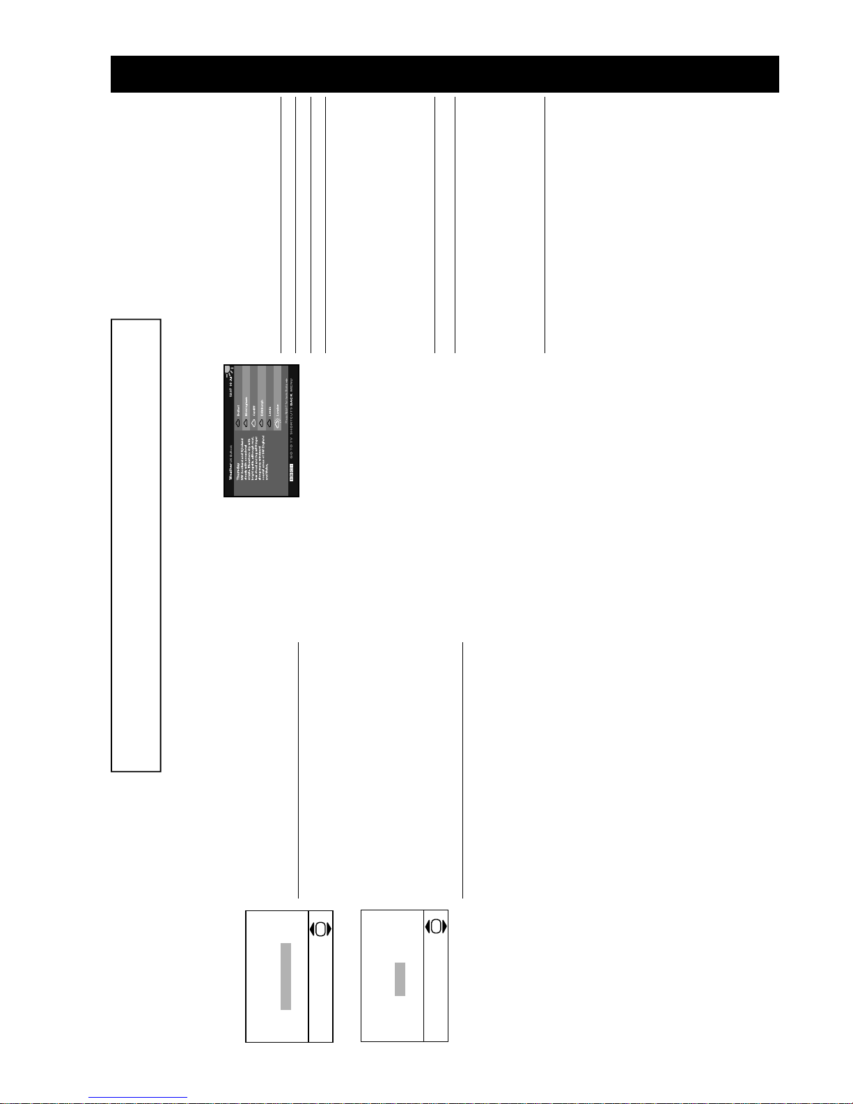
The ‘Picture Rotation’ menu.
The ‘Autotune’ prompt.
Do you want to start
automatic tuning?
Yes
No
OK
If picture slants, please
adjust picture rotation
Not necessary
Adjust now
OK
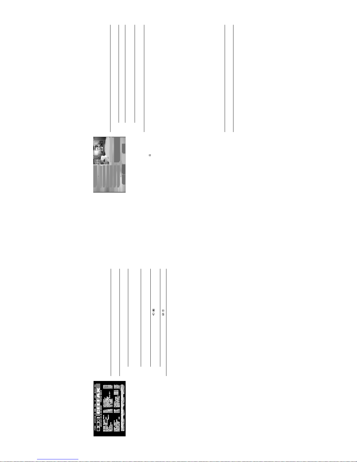
Digital text
Many broadcasters now provide a digital text service. Digital text services offer all
the familiar information that analogue (conventional) text services provide but with
the look and feel of a graphically rich website.
The appearance, content and navigation methods of all digital text services are
decided by the broadcaster. For example, digital text from the BBC may look
different from digital text from ITV. Most of the digital text services currently
available use simple navigation methods based on the following buttons:
Viewing digital text
There are two ways to view digital text, either while watching a digital channel or by
accessing a dedicated digital text channel.
a) Digital text from digital channels
(depending on availability of service)
This form of digital text is accessed the same way as analogue text.
b) Digital text from a dedicated digital text channel
(depending on availability of service)
Some broadcasters provide a separate channel for accessing their digital text
service.
To Press
Load or exit digital text... / button.
Move around the screen... V, v, B or b buttons.
Select items on screen... OK and Numbered buttons.
Access shortcuts... Coloured buttons.
1.
Select a digital channel which provides a text service.2.Press the / button to access the digital text service.3.Follow the on screen instructions.
1.
Select a dedicated digital text channel.2.Follow the on screen instructions.
An example of digital text.
The operating instructions mentioned here are partial abstracts from the ‘Operating
Instruction Manual’. The page numbers of the ‘Operating Instruction Manual’ remain
as in the manual.
SECTION 1 GENERAL
- 8 -
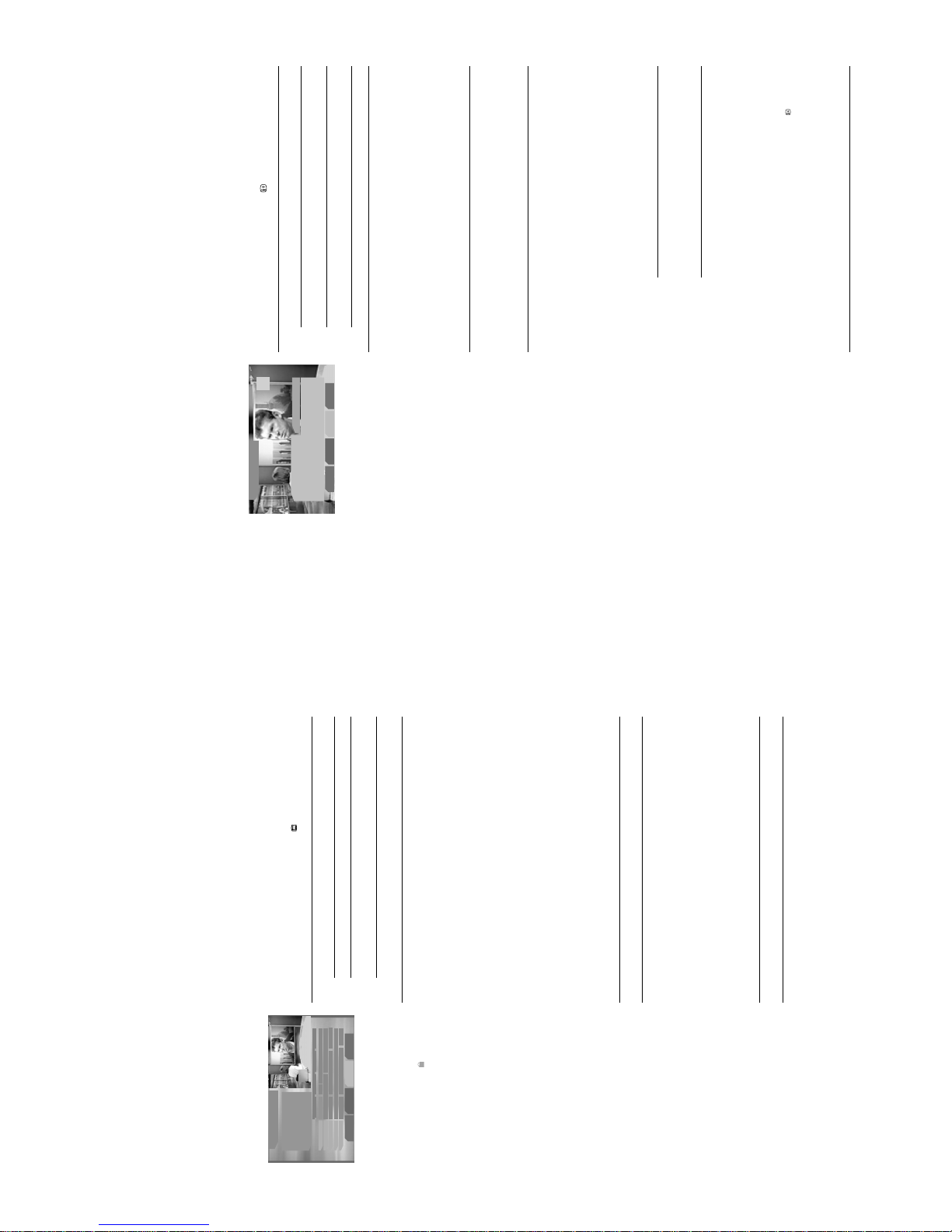
The Channel Index
menu
The Channel Index menu provides a list of all the available digital channels, along
with information about the programmes currently being broadcast. The current
channel is previewed in the top right corner o f the screen with it’s ch annel name and
number displayed below it.
The Channel Index menu is only available in digital mode.
The Category pop-up list
The Category pop-up list allows yo u to display c hannels in the Channel Inde x menu
by category.
The categories available include:
Favourite channels
This feature allows you to create a list of your favourite channels. This list is
displayed when the ‘Favourite’ categ ory is selected in the Channel Index m enu (see
above).
To add a channel to the Favourite category
With the required channel highlighted in the Channel Index menu, press the BLUE
button to add the channel to the Favourite list.
To remove a channel from the Favourite category
Access the Category pop-up list (see above). U se the V or v button to hi ghlig ht the
‘Favourite’ category. Press the OK butto n to di spl ay t he ‘Favourite’ catego ry. Us e
the V or v button to highlig ht the channe l you wish to remove from the Favourite li st.
Press the BLUE button to remove the channel.
1.
With the TV in digital mode, press the OK button to display the Channel
Index menu.
2.
To Press
Move around the menu... V and v buttons.
Display the previous/next six
channels in the list...
RED button (previous), GREEN
button (next).
Preview a programme... OK button while highlighting a
programme*.
3.
Press the DIGITAL/a button to return to normal TV operation.
Favourite Contains all the channels you have stored as a favourite (see
below).
Choice The TV will create this list based on the typ e of cha nne ls you
watch the most.
Recent Prog. Contains the last five channels watched.
All Categories Contains all available channels.
News Contains all news channels.
1.
Press the YELLOW button whilst accessing the Channel Index menu.2.Press the V or v button to highlight the required category.3.Press the OK button. The Channel Index menu no w only shows cha nnels
from the category selected. The category na me is dis play ed at the top of
the channel list.
The ‘Channel Index’ menu.
*If you have set a Parental Control age limit in t he
Main Menu, and the programme exceeds that
limit, you will be asked to enter your PIN before
the preview is allowed. Programmes that exceed
the age limit are identified by a symbol.
Initially the PIN code is preset to 1234. Refer to
‘PIN Code’ on page 20 for more information.
All Categories
Thu 3 Jul
13:07
01 BBC ONE
BBC News
02 BBC 2
Wimbledon 2003
03 ITV 1
Everything Must Go
04 CHANNEL 4
This Happy Breed
05 five
Family Affairs
06 ITV 2
Emmerdale
01 BBC ONE
Press OK key to exit Index.
Previous Next Category Add
13:00-13:30
12:00-14:30
13:00-13:30
12:45-14:45
13:00-13:30
13:00-13:30
Analogue text
Most analogue TV channels br oadcast a tex t service. The index page (u sually page
100) provides information on how to use the service. Please ensure that you are
receiving a good signa l, or some text errors may occur.
Viewing analogue text
Fastext
Fastext allows you to access pages quickly and easily. When Fastext is available,
four coloured items appear at the bottom of the te xt pag e. Press the corre spond ing
Coloured button on the remote control to access the page.
1.
Select an analogue channel that provides a text service.2.Press the / button to access the text service.
3.
To Press
Select a page... Numbered buttons. (Press the
PROG +/- buttons to display the
previous or next page).
Superimpose the text over the TV
picture (mix mode)...
/ button. Press again to exit the
text service.
Hold a page... / button. Press again to
cancel.
Reveal hidden information... / button.4.Press the DIGITAL/a button to return to normal TV operation.
An example of analogue text.
- 9 -
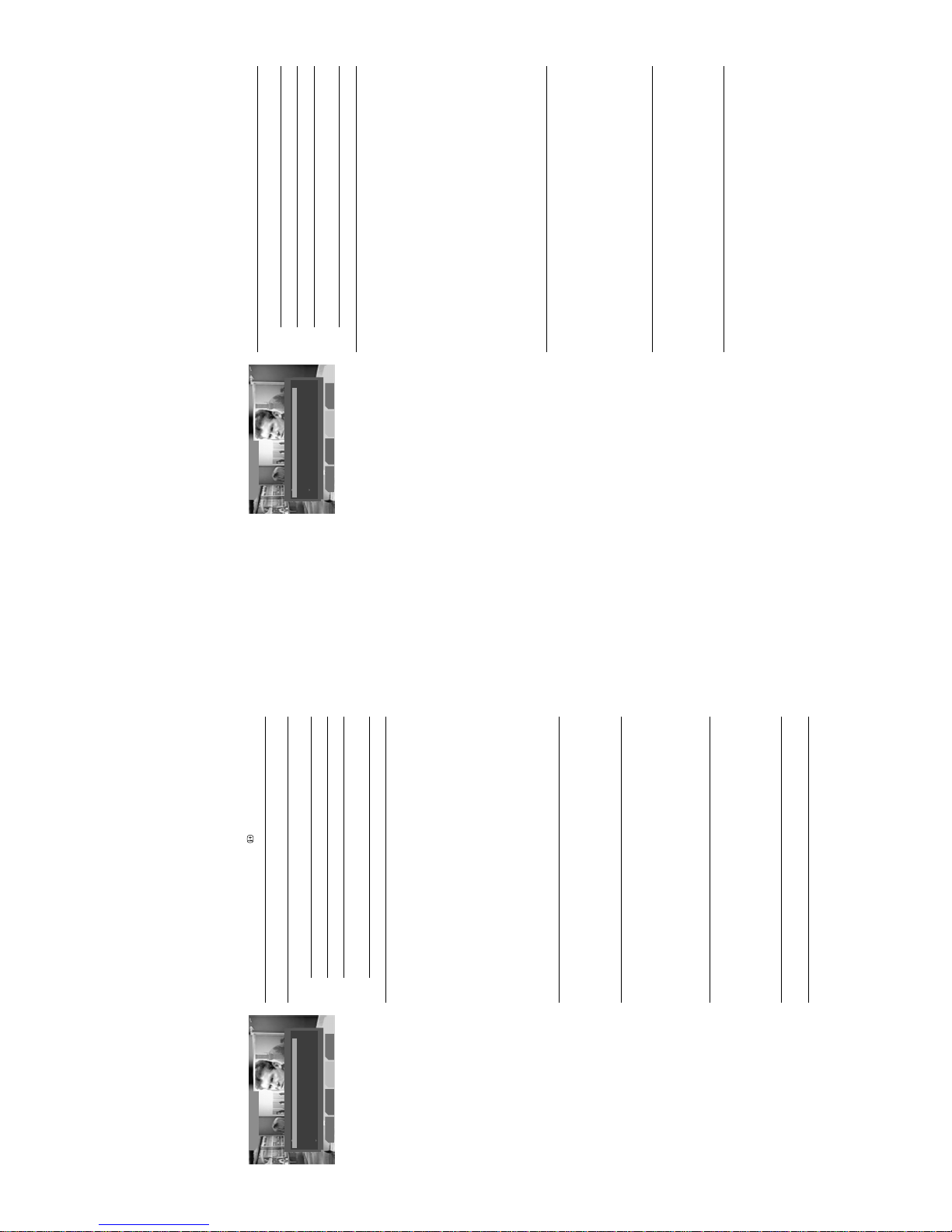
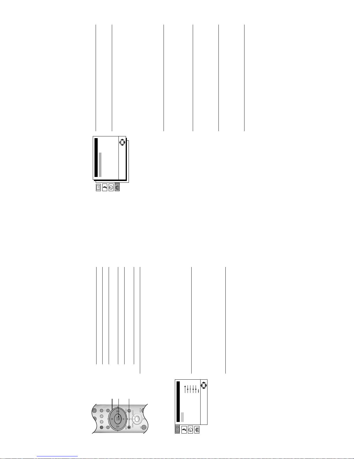
The Info menu
The Info menu provides information on the programme s currently being show n and
on future programmes. It also a llows you t o dis play digita l sub titles and l isten to the
broadcast in a different language.
The Info menu is only available in digital mode.
The Coloured buttons give you access to further options:
1.
With the TV in digital mode, press the button to display the ‘Info menu’.
2.
To Press
Display information for future
programmes...
b button.
Return to information for current
programmes...
B button.
Change the TV channel... Numbered buttons.3.Press the DIGITAL/a button to return to normal TV operation.
RED button: Subtitles
(depending on availability)
When pressed, a pop-up menu allows you to change the
languages for the subtitles. Press the V or v button to
select the language required, then press the OK button to
confirm.
GREEN button: Audio
(depending on availability)
When pressed, a pop-up menu allows you to select the
language in which you wish to hear the broadcast. Press
the V or v button to select the language required, then
press the OK button to confirm.
YELLOW button: REC/Timers
Allows you to record a programme from the Info display, or
set a programme to automatically appear on screen w hen
it starts. Press the B or b button to select future
programmes from the Info display, then press the
YELLOW button to display the ‘Timers’ pop-up menu. You
can now choose from a)Record b)Wakeup or c)Manual
a) Record** Highlight ‘Record’ and press OK to
automatically set your VCR to record the
selected programme (t his will only work if
your VCR has the Smartlink facility and is
connected to the AV2 socket i2/r on
the rear of this TV).
b) Wakeup** Highlight ‘Wakeup’ and press OK if you
wish the future programme you selected
to appear on screen when transmission
begins.
c) Manual*** Highlight ‘Manual’ and press OK if you
wish the TV to output a channel to your
VCR for recording. The display shown on
the left appears. Press the V or v button
to set the day of recording, then press the
b button to move to the start time. Repeat
this procedure to set the start and stop
times and the channel number, then
press the OK button to store and return to
the Info menu. Press the button to
remove the Info menu from the screen.
Unless you have a Smartlin k VCR, you
must now set the timer recording function
of your VCR to switch on and off to
correspond with the program me you have
stored for recording.
BLUE button: Press to display the Main Menu (see next page).
**After you have programmed a recording you
can put the TV into it’s standby mode, but do not
switch off completely or the recording will be
cancelled. If you put the TV into standby mode,
the standby indicator on the front of the TV
flashes green periodically to remind you a
recording has been programmed. Once a
programme has started recording, do not change
channels or switch to analogue mode or the
recording will be cancelled.
***The ‘Manual’ feature only works if you have
connected your VCR to the AV2 socket i2/r
on the rear of the TV.
The ‘Info’ menu.
All Categories
Thu 3 Jul
13:07
Subtitles
01
Set-upAudio
BBC News; Weather
All the latest news and sport.
Regional News; Weather
13:30-13:45
The Digital Electronic
Programme Guide
(EPG)
The Digital Electronic Programme Guide allows you to:
a) view programme information for all digital channels,
b) sort programme information by category,
c) set reminders to have the TV a utomatic ally swi tch t o a prog ramme whe n it sta rts,
d) record programmes
The Digital Electronic Programme Guide is only available in digital mode.
The Category pop-up list
The Category pop-up list allows you to display channels in the Digital Electronic
Programme Guide by cate gory.
The categories available include:
To add/remove a channel to/from the Favourite list
Refer to ‘To add a channel to the Favourite category’ and ‘To remove a channel
from the Favourite category’ on the previous page.
Recording
1.
With the TV in digital mode, press the button to display the Digital
Electronic Programme Guide.
2.
To Press
Move around the menu... V, v, B and b buttons.
Display the previous/next five
channels in the list...
RED button (previous), GREEN
button (next).
Preview a programme... OK button while highlighting a
programme*.
4.
Press the DIGITAL/a button to return to normal TV operation.
Favourite Contains all the channels you have stored as a favourite
(see below).
Choice The TV will create this list based on the type of channels
you watch the most.
Recent Prog. Contains the last five channels watched.
All Categories Contains all available channels.
News Contains all news channels.
1.
Press the YELLOW button whilst accessing the Digital Electronic
Programme Guide.2.Press the V or v button to highlight the required category.3.Press the OK button. The Digital Electronic Programme Guide now only
shows channels from the category selected. The category name is
displayed at the top of the channel list.
1.
With the Digital Electronic Programme Guide on screen, press the V, v,
B and b button to highlight the programme you wish to record.2.Press the OK button to display the ‘Timers’ menu.3.Press the RED button to set the TV and your VCR timers**.
**For Smartlink VCRs only. If your VCR does not
have Smartlink a message will be displayed to
inform you. Press the RED button to set the TV
timer. You will now have to manually set your
VCR timer.
When a programme has been set to record, a
solid green bar appears under the information
box in the EPG for that programme.
*If you have set a Parental Control age limit in t he
Main Menu, and the programme exceeds that
limit, you will be asked to enter your PIN before
the preview is allowed. Programmes that exceed
the age limit are identified by a symbol.
Initially the PIN code is preset to 1234. Refer to
‘PIN Code’ on page 20 for more information.
The ‘Digital EPG’.
All Categories
Thu 3 Jul
13:07
01 BBC ONE
BBC News
01 BBC ONE
Previous Next Category
All the latest news and sport.
Timer List
Press OK key to exit
13:00 13:30 14:00 14:30
02 BBC 2
03 ITV 1
04 CHANNEL 4
05 five
BBC News Reg...Wimbledon 2003
Wimbledon 2003 The Bride Walks Out
Everything... Quincy, ME Shortland...
This Happy Breed
Family Aff... Brain Teaser Charlie's..
- 10 -
Detail Set-up menu
This menu allows you to configure the digital side of your TV.
1.
With the TV in digital mode, press the OK button to display the Channel
Index menu.
2.
To Press
Highlight an option... V and v buttons.
Select a highlighted option... OK button.
Alter the settings of a selected
option...
V, v, B or b buttons.
Store settings/changes... OK button.
3.
Press the DIGITAL/a button to return to normal TV operation.
Manual Tuning
This option allows you to tune digital channels one by one.
With the ‘Manual Tuning’ option highl i gh t ed, pr e ss th e OK button to display the
‘Manual Tuning’ menu. Press the V or v button to highlight the channel number
for your new channel. (Alternatively, p ress t he RED or GREEN button to display
the previous or next five channels in the li st.) Press the OK button to displa y the
‘Manual Programme Search’ menu. Press the b button to highlight ‘Select
Search’. Press the V or v button to start searching. All the available channels
are displayed on the right side of the menu. Press the V or v button to highlight
the required channel. Press the OK button to store .
Clearing a channel
With the ‘Manual Tuning’ option highl i gh t ed, pr e ss th e OK button to display the
‘Manual Tuning’ menu. Press the V or v button to highlight the channel number
you wish to clear. Press th e YELLOW button. A message is displayed asking
you to confirm. Press the RED button to clear the channel or press the BLUE
button to cancel.
PIN Code
This option allows you to change your PIN code.
With the ‘PIN Code’ option highlighted, press the OK button to display the ‘PIN
Code’ menu. Use the Numbered buttons to en ter your existing PI N code. Initial ly
the PIN code is preset to 1234. If you enter a wrong number, press the RED
button to clear and start again. If you have forgotten your PIN code, please use
9999. This Pin Code will always be accepted. Press the OK button to confirm.
Use the Numbered buttons to enter your new PIN code. Press the OK button to
confirm. Enter your new PIN again to confirm. Press the OK button to change
the PIN.
Software Download
This option allows you to receive software updates, free through your existing
aerial (when issued). Sony reco mmends tha t this opti on is set to ‘On’ at all tim es.
If you do not wish your software to be updated, set this option to ‘Off’.
With the ‘Software Download’ option highli ghted, press th e OK button to confirm.
Press the V or v button to select ‘On’ or ‘Off’. Press the OK button to confirm.
System Information
This is an information screen only and displays the current software versions
and the signal strength.
With the ‘System Information’ option highl ighted , press th e OKbutton to display
the ‘System Information’ screen.
The ‘Detail Set-up’ menu.
Digital Set-up
Detail Set-up
Press OK key to enter
Manual Tuning
PIN Code
Software Download
System Information
Back
The Main Menu
This menu contains features that allow you to cus tomise the digital side of yo ur TV.
The ‘Main Menu’ is only available in digital mode.
1.
With the TV in digital mode, press the button to display the ‘Info menu’.2.Press the BLUE button to access the ‘Main Menu’.
3.
To Press
Highlight an option... V and v buttons.
Select a highlighted option... OK button.
Alter the settings of a selected
option...
V, v, B or b buttons.
Store settings/changes... OK button.
4.
Press the DIGITAL/a button to return to normal TV operation.
Favourite Progra mm e
This option allows you to s t ore y our fav ou rite c han nel s in a list for quick access.
To add a channel to the Favourite Programme list
With the ‘Favourite Programmes’ option highlighted, press the OK button to
display the ‘Favouri te Programmes’ menu. Press the V or v button to scroll
through the list until the channel you wish to store as a favourite is highlighted.
Press the OK button to confirm. A tick appears a longside th e channe l to indic ate
that it is now stored as a favourite. Repeat this proced ure to store other favou rite
channels.
To remove a channel from the Favourite Programme list
Highlight the channel and press the OK button. The tick disappears.
To remove all channels from the Favourite Programme list
Press the YELLOW button.
Wallpaper
This option allows you to customise the backg round pattern for all digital menus .
With the ‘Wallpaper’ option highlighted, press the OK button to display the
‘Wallpaper’ menu. Press the V or v button to highlight the required wallpaper.
Press the OK button to confirm.
Parental Control
This option allows you to set an age limit above which a PIN code is required
before viewing is all owed.
With the ‘Parental Control’ option highlight ed, press the OK b utton to di splay the
‘Parental Control’ menu. Enter your existing PIN code using the Numbered
buttons*. Press the OK button to confirm. The age box now becomes active.
Press the V or v button to highlight the required age limit. Press the OK button
to confirm.
Auto Tuning
All the available digital channels were tuned in when the TV was first installed.
This option allows you to repeat that process (e.g. to search for new channels
that have been launched by broadcasters).
With the ‘Auto Tuning’ option highlighted, press the OK button to display the
‘Auto Tuning’ menu. Press the RED button to start the auto tuning process.
Detail Set-up
The ‘Detail Set-up' menu is explained on page 20.
CA Set-up
The ‘CA Set-up' option is for future use only.
The ‘Main’ menu.
*Initially the PIN code is preset to 1234. Refer to
‘PIN Code’ on page 20 for details on how to
change this.
Digital Set-up
Exit
Main Menu
Press OK key to enter
Favourite Programmes
Wallpaper
Parental Control
Auto Tuning
Detail Set-up
CAM Set-up
- 11 -
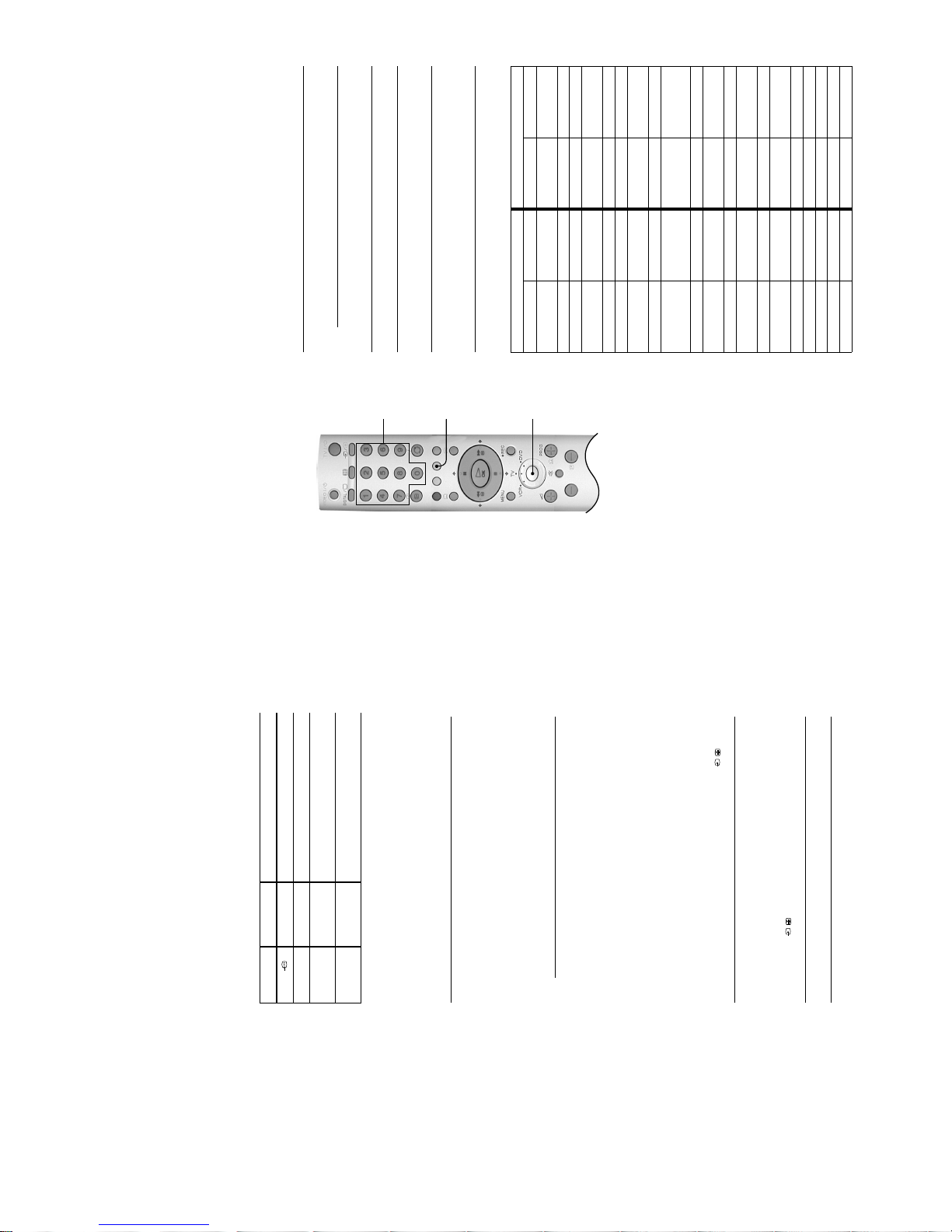
Using the TV menu
system
Use the following buttons to operate the TV menu system.
The individual menus are explained on the following pages.
Picture Adjustment menu
1.
To Press
Access the TV menu system... MENU button.
Highlight an option... V or v buttons.
Enter the highlighted menu or
option...
b button.
Return to the last menu or option... B button.
Alter the settings of a selected
option...
V, v, B or b buttons.
Store settings/changes... OK button.
2.
Press the MENU button to return to normal TV operation.
Mode
This option allows you to choose between three picture mode settings, ‘Live’,
‘Movie’ and ‘Personal’. ‘Live’ and ‘Movie’ are preset and only the ‘Contrast’
setting can be adjusted. ‘Personal’ mode ho weve r, also allows you to adjust the
‘Brightness’, ‘Colour’ and ‘Sharpness’ settings.
With the ‘Mode’ option highlighted, press the b button to ad jus t. Pr ess th e V or
v button to select the required mode. Press the OK button to confirm.
Contrast, Brightness, Colour, Sharpness, Hue
These options allow you to adjust the contrast, brightness, contrast, sharpness
and hue.
‘Brightness’, ‘Colour’ and ‘Sharpness’ can only be adjusted when the picture
‘Mode’ is set to ‘Personal’. ‘Sharpness’ is not adjustable in digital mode. ‘Hue’ is
only available when viewing an NTSC colour signal, e.g. USA video tapes.
With the required option highli ghted, press the b button to adjust. Press the B or
b button to set the level. Press the OK button to confirm.
Reset
This option resets all picture settings to the factory preset levels.
With the ‘Reset’ option hi ghlighted, press the OK button to restore defa ult picture
settings.
OK
button
V, v, B, and b
buttons
MENU
button
The ‘Picture Adjustment’ menu.
Picture Adjustment
Mode: Personal
Contrast
Brightness
Colour
Sharpness
Hue
Reset
OK
Manual Programme
Preset menu
This menu allows you to tune in analogue channels, one by one.
1.
With the ‘Manual Programme Preset ’ option highlighted, press the OK
button to display the ‘Manual Programme Preset’ menu. 2.Press the b button to highlight the programme number. Press the V or v
button to select the channel number you wish to manually tune (if tuning
a VCR, please select channel 0). Press the B button to highlight
‘Programme’.3.Press the v button to highlight ‘Channel’. Press the b button to highlight
the setting. You now need to tune the channel by one of the following
methods:
a) If you do not know the channel number (frequency):
Press the V or v button to search for the next available channel.
(When a channel has been found the search will stop , pres s the V or
v button to continue searching.)
b) If you know the channel number (frequency):
Use the Numbered buttons to enter the channel number of the
broadcast you want or your VCR channel number.
Once you have stored a channel, press the B button to highlight
‘Channel’.
4.
Press the v button to highlight ‘Label’. This option allows you to assign a
name of your choice (up to 5 letters or number). The name is displayed
briefly on screen when the channel is selected.
Press the b button to highlight the setting. Press the V or v button until
the letter or number you require appears in the display (select ‘-’ for a
blank space). Press the b button to confirm. Repeat this until the name
is complete. Press the B button repeatedly to highl igh t ‘Label’.5.Press the v button to highlight ‘AFT’. Normally, fine tuning is performed
automatically, However, this op tion allow s you to a djust it manuall y if you
feel that a slight tuning adjustment will improve the picture quality.
Press the b button to highlight the setting. Press the V or v button to
adjust the fine tuning over a range of -15 to +15, or select ‘On’ for
automatic fine tuning. Press the B button to highlight ‘AFT’.
6.
Press the v button to highlight ‘Skip’. This option allows you to skip
unused analogue channels when selecting channels with the PROG +/-
buttons. (You can still select a skipped channel using the Numbered
buttons on the remote control.)
Press the b button the setting. Press the V or v button to select ‘Yes’ or
‘No’. Press the B button to highlight ‘Skip’.
7.
Press the v button to highlight ‘Confirm’. Press the OK button to store any
changes.
The ‘Manual Programme Preset’ menu.
Manual Programme Preset
Programme:
Channel:
Label:
AFT:
Skip:
Confirm
01
C 41
-----OnNo
OK
- 12 -
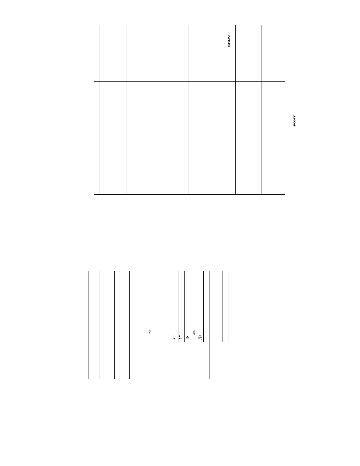
Remote control of
other equipment
The remote control supplied with your TV automatically operates the basic
functions of Sony DVD players and most Sony VCRs. The remote control can also
operate DVD players and VCRs made by other manufacturers, provided that it is
first programmed to match the particular brand of your VCR or DVD player**.
Programming the remote control
1.
Find the three digit code for your brand from the list below.2.If programming the remote control to operate a DVD player:
Press the Mode Selector button repeatedly until the green DVD light
illuminates.
If programming the remote control to operate a VCR:
Press the Mode Selector button repeatedly until the green VCR light
illuminates. 3.With the green light illuminated, press and hold down the YELLOW
button for approximately six seconds, until the light starts to flash.4.Use the Numbered buttons to enter the three digit code for your brand.
Once a correct code has been entered, the green VCR, TV and DVD
lights illuminate together momentarily.
5.
Turn on your VCR or DVD player and check that the remote control
operates the basic functions (refer to ‘Controlling a DVD player’,
‘Controlling a VCR’ on the next page for details). If not, repeat steps 2-4
and enter the next three digit number for your brand.
6.
Press the Mode Selector button repeatedly until the green TV light
illuminates.
DVD Brand List VCR Brand List
Brand Code Brand Code
SONY 001 SONY (VHS) 301, 302,
303, 308, 309
AIWA 021 SONY (BETA) 303, 307, 310
DENON 018, 027, 020, 002 SONY (DV) 304, 305, 306
GRUNDIG 009, 028, 023,
024, 016, 003
AIWA 325, 331, 351
HITACHI 025, 026, 015, 004 AKA I 326, 329, 330
JVC 006, 017 DAEWOO 342, 343
KENWOOD 008 GRUNDIG 358, 355, 360
361, 320, 351
LG 015, 014 HITACHI 327, 333, 334
LOEWE 009, 028, 023,
024, 016, 003
JVC 314, 315, 322,
344, 352, 353,
354, 348, 349
MATSUI 013, 016 LG 332, 338
ONKYO 022 LOEWE 358, 355, 360
361, 320, 351
PANASONIC 018, 027, 020, 002 MATSUI 356, 357
PHILIPS 009, 028, 023,
024, 016, 003
ORION 328
PIONEER 004 PANASONIC 321, 323
SAMSUNG 011, 014 PHILIPS 311, 312, 313, 316,
317, 318, 358, 359
SANYO 007 SAMSUNG 339, 340, 341, 345
SHARP 019, 027 SANYO 335, 336
THOMSON 012 SHARP 324
TOSHIBA 003 THOMSON 319, 350
YAMAHA 018, 027, 020, 002 TOSHI BA 337
VIDEO
/
TV
/
DIGITAL
Numbered
buttons
Mode
Selector
button
YELLOW
button
*The brand codes you set may be lost if weak
batteries are not replaced immediately. Should
this happen, replace the batteries and re-enter
the required codes. A small label has been
attached to the battery holder for you to make a
note of your brand codes.
continued on next page .
Connecting other
equipment to the TV
A wide range of equipment can be connected to the TV through the front and rear
sockets. Most equipment can be connected to any of the TV sockets. Refer to the
instruction manual supplied with your equipment to determine the best TV socket
to use. This TV supports the following inputs:
Viewing pictures from
a connected VCR
If you have used a fully wired 21-pin scart lead to connect the VCR:
Refer to ‘Viewing pictures from equipment connected to the rear sockets’, below.
If you have not used a fully wired 21-pin scart lead to connect the VCR:
You will need to find the video channel:
Viewing pictures from
equipment connected
to the rear sockets
Viewing pictures from
equipment connected
to the front sockets
TV Sockets Socket type(s) Inputs supported
i1/ Scart RGB, Audio/Video.
i2/r Scart S-Video, Audio/Video, Smartlink*.
o3 and
r3 Phono (x2),
4 pin DIN
Audio/S-Video.
(audio via o3 sockets, S-Video vi a r3 socket)
o3 and t3 Phono (x3) Audio/Video.
(audio via o3 sockets, video via t3 socket)
1.
Insert a pre-recorded tape into the VCR and press the ‘PLAY’ button.2.If you inserted a pre-recorded tape and pressed ‘PLAY’ during the
autotune process, as instructed on page6:
With the TV in analogue mode, press the PROG +/- buttons until the
picture from the pre-recorded tape is displayed on the TV screen.
In future, with the TV in analogue mode, press the Numbered buttons to
directly select the video channel.
If you wish to move your video channel, refer to the ‘Programme Sorting’
on page 23.
If you did not insert a pre-recorded tape and press ‘PLAY’ du ring the
autotune process, as instructed on page6:
You will need to manually tune in the VCR signal (ideally to channel 0).
Insert a pre-recorded tape into the VCR and press the ‘PLAY’ button.
Refer to the ‘Manual Programme Preset menu ’ s ec tio n of this in struction
manual to manually tune in the VCR signal.
After manually tuning the VCR signal and w ith th e TV in an alogu e mode ,
press the Numbered buttons to directly select the video channel.
1.
Switch on/press ‘PLAY’ on the connected equipm ent. The pict ure (if any)
from the equipment appears on the TV screen.
If the picture does not automatically appear press the / button
repeatedly until the picture is displayed on the TV screen.
2.
Press the DIGITAL/a button to return to normal TV operation.
1.
Press the / button repeatedly until the t3 symbol appears on the
TV screen.
2.
Switch on/press ‘PLAY’ on the connected equipm ent. The pict ure (if any)
from the equipment appears on the TV screen.
3.
Press the DIGITAL/a button to return to normal TV operation.
*Smartlink is a direct link between the TV and a
compatible VCR or DVD recorder. Ensure that
your VCR/DVD recorder is connected to the
scart socket labelled i2/r, using a fully wired
21 pin scart lead. For more information on
Smartlink, refer to the instruction manual
supplied with your Smartlink VCR/DVD recorder.
- 13 -
Troubleshooting
Here are some simple solutions to problems which may affect the picture and sound.
Problem Cause Solution
No picture, no sound. • Power off.
• TV in standby.
• Aerial disconnected.
• Plug in the TV.
• If the 1 indicator is lit, press the
TV I/1 button on the remote control.
• Press the ! button on the front of the
TV.
• Check aerial connection.
Poor or no picture (screen is dark), good
sound.
• Low picture settings. • Access the ‘Picture Adjustment’
menu and adjust the ‘Brightness’,
‘Colour’ and ‘Contrast’ settings.
Refer to page 21.
No picture on any channel after digital
tuning.
• No digital transmissions in your area.
• Weak signal.
• Unsuitable aerial.
• Tune in all available analogue
channels. Refer to ‘Manual
Programme Preset’ on page24.
Contact a local installer to find out
when digital transmissions begin in
your area.
• Ensure aerial/satellite dish is
correctly aligned to transmitter.
• Ensure aerial is plugged directly into
the TV (not through other
equipment).
• Upgrade to a higher gain aerial.
• Upgrade to a higher gain aerial.
Some channels are blank. • Scrambled/Subscription only
channel.
• Chann el not being transmitted.
• Channel used only for data (no
picture or sound).
• Subscribe to the pay-per-view
service.
• Contact the broadcaster for
transmission details
Standby indicator flashing. • Digital programme set for ‘Timer
Record’ (regular flash).
• Fault (irregular flashing).
• Refer to ‘The Info menu’ on page 18.
• Do not open the cabinet, refer to
qualified personnel.
• Contact your nearest
Service Centre.
Good picture, no sound • Low or muted volume • Press the 2 + button on the remote
control.
• If % is displayed, press the % butto n
on the remote control.
No colour on colour programmes. • Low colour level settings. • Access the ‘Picture Adjustment’
menu and adjust the ‘Colour’ setting.
Refer to page 21.
Remote control does not work. • Batteries low.
• Wrong mode selected
• Replace batteries.
• Press the Mode Selector button
repeatedly to select TV mode.
Distorted picture when changing
programmes or selecting text.
• Connected equipment switched on. • Switch off external equipment (VCR,
DVD player etc.)
• If you continue to have these problems, have your TV serviced by qualified
personnel or contact the UK Digital HelpLine on 0870 600 1717.
• NEVER open the casing yourself.
Specifications
TV System
I/DVB-T
Colour System
PAL
NTSC 3.58, 4.43 (only Video In)
MPEG-2 MP@ML
Channel Coverage
UHF: B21-B69
Picture Tube
KD-28DX50: FD Trinitron WIDE Approx. 71cm (28inches)
KD-32DX50: FD Trinitron WIDE Approx. 82cm (32inches)
Sound Output
Left/Right: 2x14W (music power), 2x7W (RMS)
Power Consumption
KD-28DX50: 97W
KD-32DX50: 97W
Dimensions (w x h x d)
KD-28DX50: Approx. 788 x 571 x 563 mm
KD-32DX50: Approx. 886 x 620 x 592 mm
Weight
KD-28DX50: Approx. 45kg
KD-32DX50: Approx. 61kg
Rear Terminals
i1/ 21-pin Euro connector (CENELEC
standard) including audio/video input,
RGB input, TV audio/video output.
i2/r 21-pin Euro connector (CENELEC
standard) including audio/video input,
S-VIDEO input, selectable audio/
video output.
1 RF In (Digital)
2 RF In (Analogue)
RF Out
Audio output - phono jacks.
PCMCIA (for future use only).
MODEM MODEM jack (for service o nly).
Front Terminals
i Headphone jack - minijack stereo.
r3 S-Video input - 4 pin DIN
t3 Video input - phono jack.
o3 Audio input - phono jack.
Supplied Accessories
RM-933 remote control (1)
IEC designated size AA (R03) battery (2)
RF Lead.
Design and specification are subject to change without notice.
- 14 -
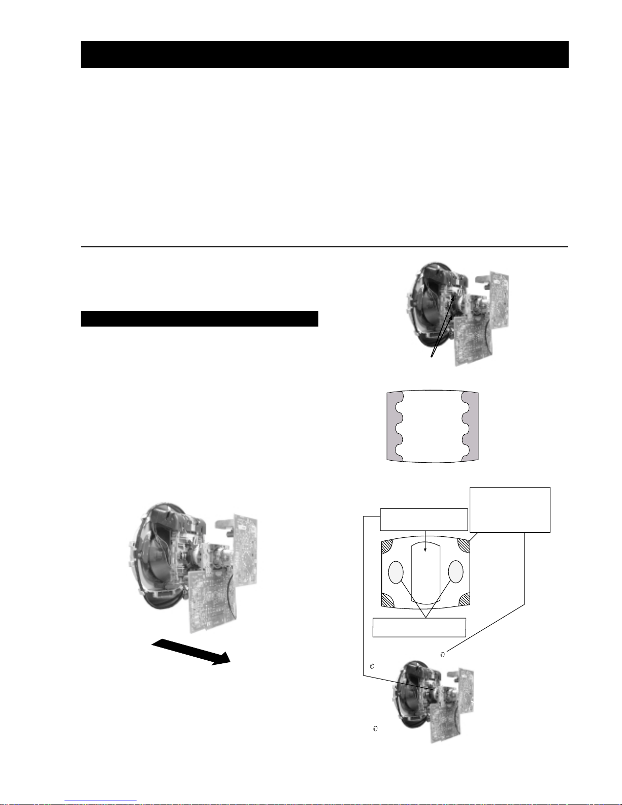
SECTION 2 DISASSEMBLY
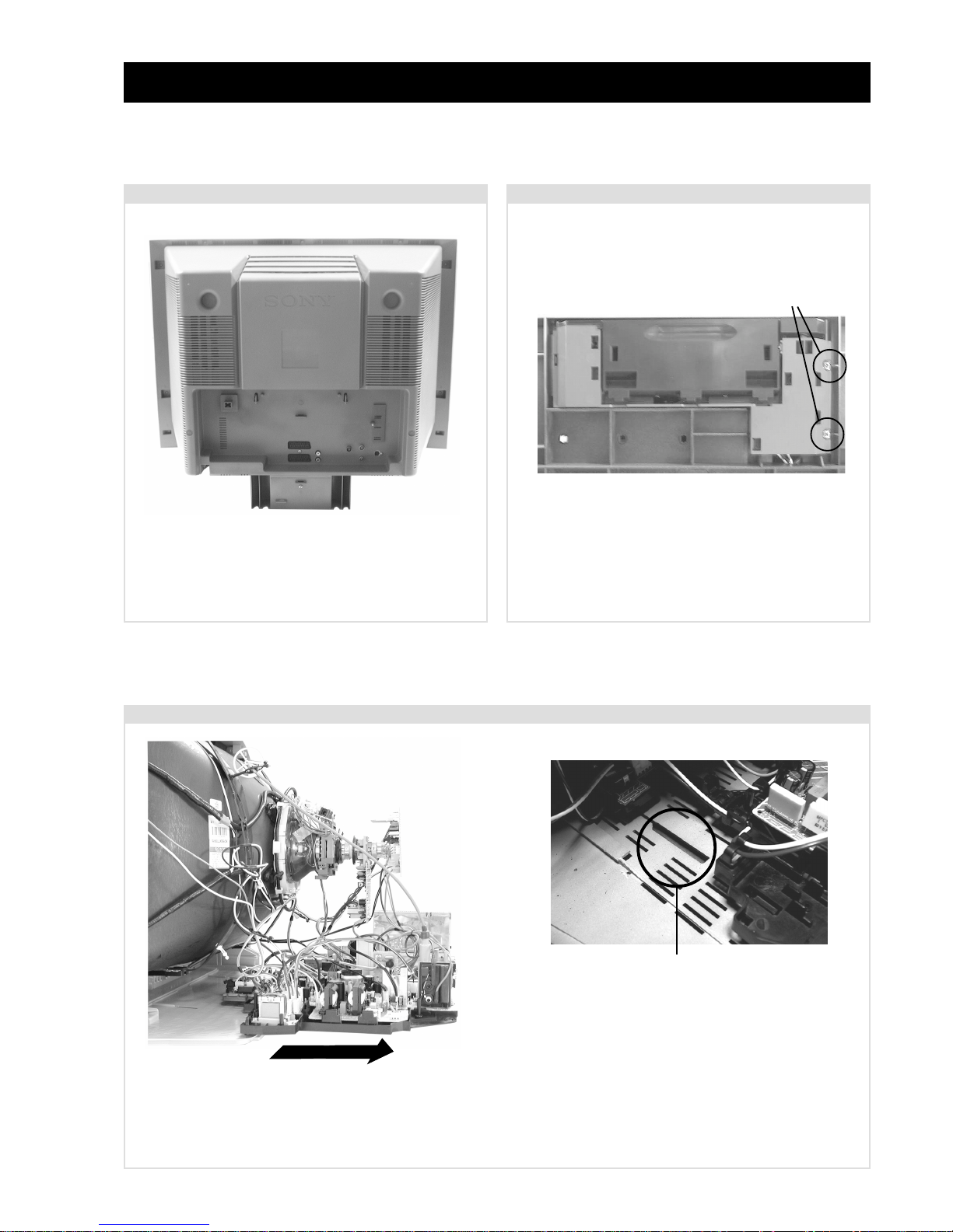
To remo ve lift the main bracket rear slightly and slide the
chassis away from the beznet. Ensure that the interconnecting
leads are released from their purse locks to prevent damage
being caused.
When refitting the chassis ensure that the main
bracket is located in the beznet guide slots before
sliding the chassis forwards. Refit the
interconnecting leads in their respective purse locks.
2-3. Chassis Removal and Refitting
2-1. Rear Cover Removal 2-2. Front Control Module Removal
=>
=>
=>
=>
=>
=>
=>
=>
=>
=>
=>
Remove the rear cover fixing screws indicated and pull the
rear cover carefully backwards.
Remove the two screws fixing the user control module to the
front underside of the set. The control module drops down to
allow access to the boards.
Screws
=>
- 15 -
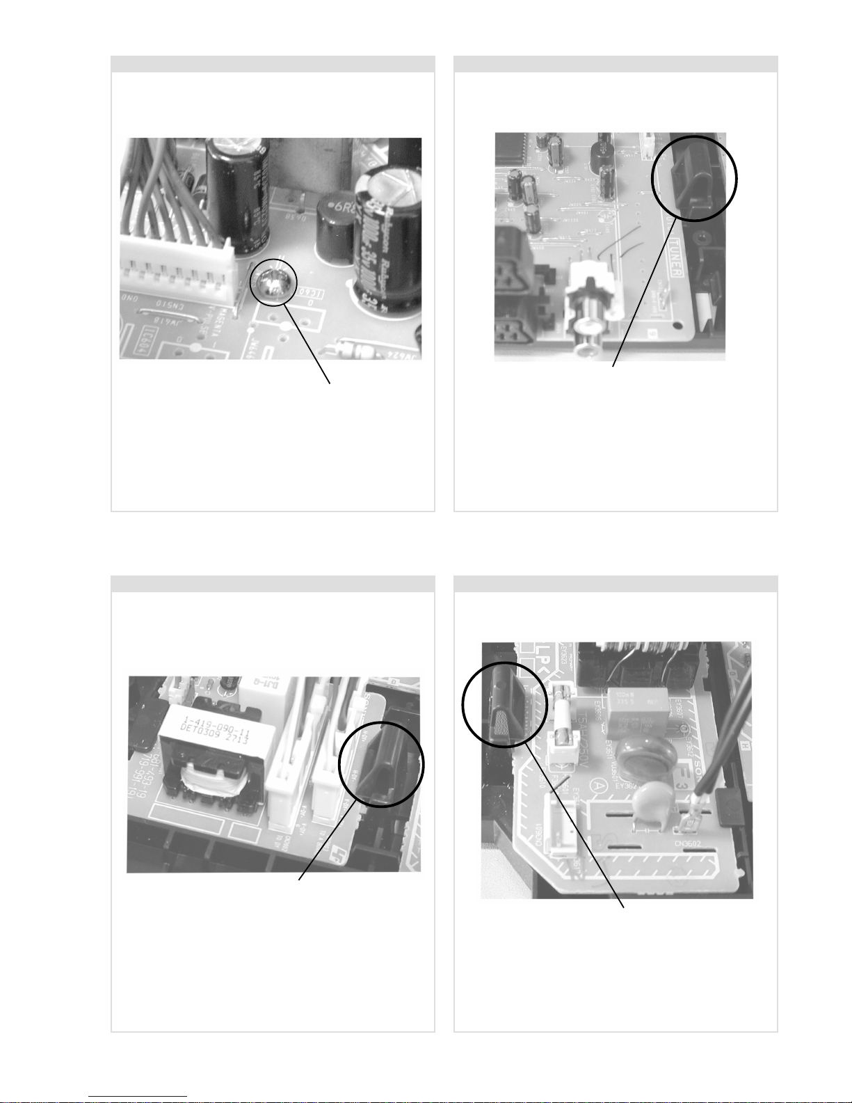
2-6. D3 Board Removal
2-4. A Board Removal [ Step 1 ] 2-5. A Board Removal [ Step 2 ]
2-7. F3 Board Removal
Screw.
Release the 5 securing clips located around the side of the
chassis and slide the PWB clear of the bracket.
Remove the 3 screws securing the PWB to the main bracket.
1 can be seen in the photo above and the other 2 are either
side of the FBT assembly.
Clip.
Release the securing clip circled and slide the PWB clear of
the bracket.
Clip.
Release the 2 securing clips located along the side of the
chassis and slide the PWB clear of the bracket.
Clip.
- 16 -
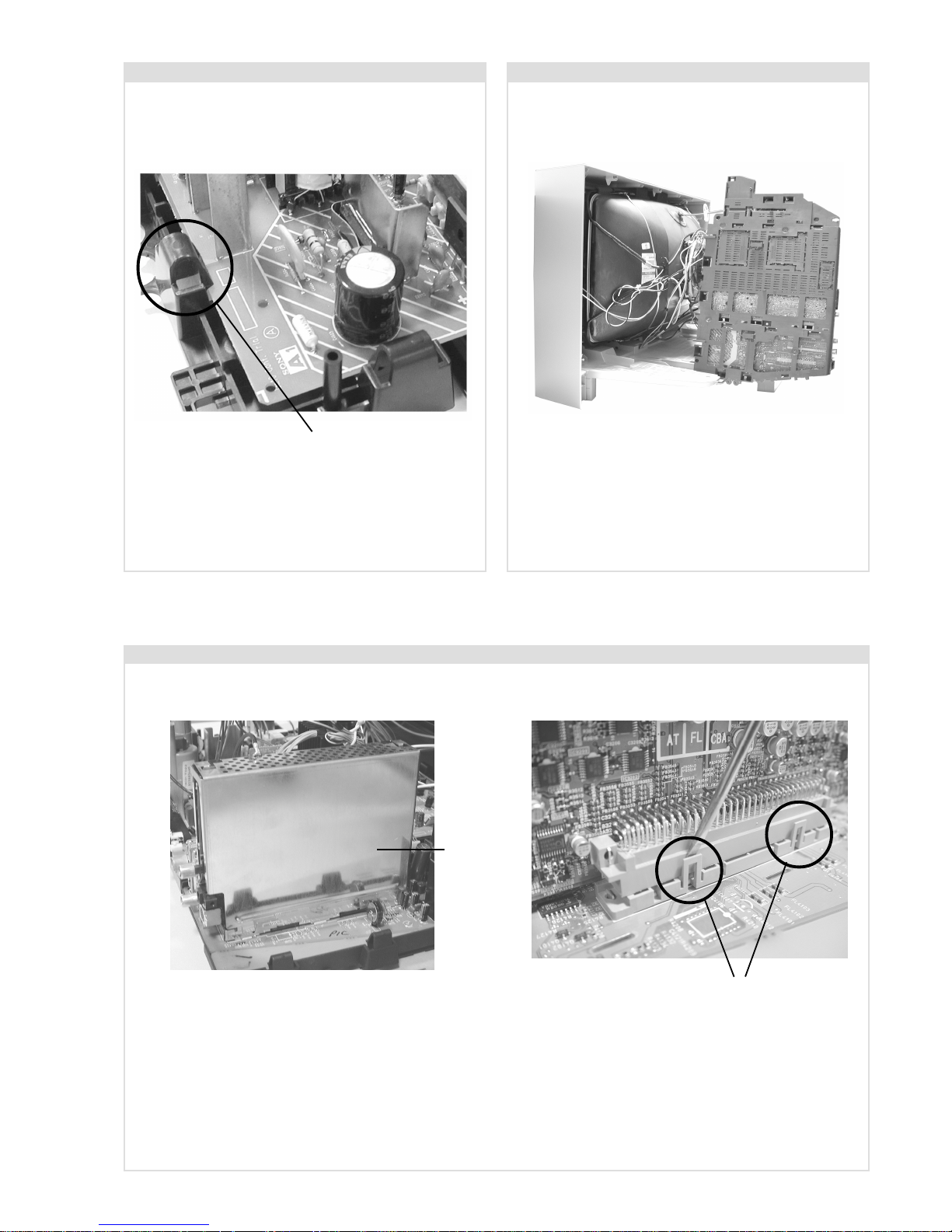
2-8. A1 Board Removal 2-9. Service Position
Position the chassis as indicated to access the solder side
of the PWB’s. T o gain access to the A Board follo w the
instructions on page 18. [Removal and Replacement of the
main bracket bottom plates ].
Remove the shield case by pulling vertically until it is clear of the N Board. Release the N board socket retaining clips, circled, by
gently prising them with a screwdriver and carefully lift the N Board v ertically .
2-10. N Board Removal
Clips
Shield
case
Clip.
Release the 4 securing clips located around the side of the
chassis and slide the PWB clear of the bracket.
- 17 -
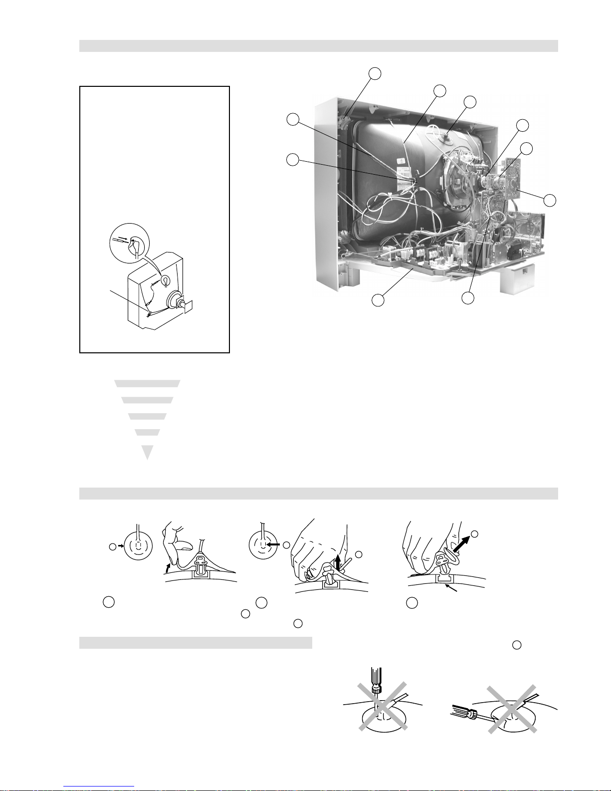
Anode button
a
* REMOVING PROCEDURES.
Turn up one side of the rubber cap in
the direction indicated by the arrow a
1
2 Using a thumb pull up the rubber cap
firmly in the direction indicated by the
arrow b
3 When one side of the rubber cap is
separated from the anode button, the
anode-cap can be removed by turning
up the rubber cap and pulling it up in
the direction of the arrow c
b
b
c
How to handle the Anode-Cap
1. To prevent damaging the surface of the anode-cap do not use
sharp materials.
2. Do not apply too great a pressure on the rubber, as this may cause
damage to the anode connector.
3. A metal fitting called a shatter hook terminal is fitted inside the
rubber cap.
4. Do not turn the rubber foot over excessively, this may cause
damage if the shatter hook sticks out.
Removal of the Anode-Cap
2-11. Picture Tube Removal
WARNING:
BEFORE REMOVING
THE ANODE CAP
High voltage remains in the CRT even
after the power is disconnected. To
avoid electric shock, discharge CRT
before attempting to remove the anode
cap. Short between anode and CRT
coated earth ground strap.
Coated Earth
Ground Strap
1. Discharge the anode of the CRT and remov e the anode cap.
2. Unplug all interconnecting leads from the Deflection yoke, neck
assy, de gaussing coils and CRT grounding strap.
3. Remove the C Board from the CRT.
4. Remove the chassis assembly.
5. Loosen the Neck assembly fixing screw and remove.
6. Loosen the Deflection yoke fixing screw and remove.
7. Place the set with the CRT face do wn on a cushion and remove
the Degaussing Coil holders.
8. Remove the Degaussing Coils.
9. Remove the CRT grounding strap and spring tentioners.
10. Unscrew the four CRT fixing screws [ located on each CRT
corner ] and remove the CR T .
[T ake care not to handle the CR T by the neck.]
1
4
6
8
10
5
9
2
7
3
- 18 -
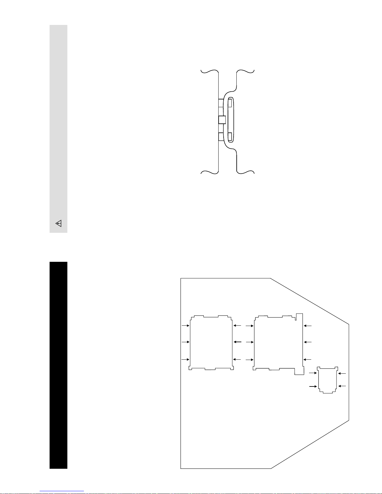
REMOV AL AND REPLA CEMENT OF THE MAIN-BRACKET
BOTT OM PLA TES.
(1) REMOVING THE PLA TES
In the event of servicing being required to the solder side of the A Board printed wiring board, the
bottom plates fitted to the main chassis bracket require to be removed.
This is performed by cutting the gates with a sharp wire cutter at the locations indicated by the
arrows.
Note : There are 3 plates fitted to the main bracket.
Only remove the necessary plate to gain access to the printed wiring board.
(2) REFITTING THE PLATES
Because the plates differ in size it is important that the correct plates are refitted in their original
location.
Please note that the plates need to be rotated 180 degrees from their cut position to allow the tabs to
be fitted into their catch positions.
For safety reasons, on no account should the plates be re-
moved and not refitted after servicing.
Tab
Catch
- 19 -
Purity control corrects
this area
Disk magnets or
rotatable disk
magnets correct
these areas (a-d)
Deflection yoke positioning
corrects these areas
Disk Magnets
a
cd
b
GREEN
BLUE
RED
Preparation:
1. In order to reduce the influence of geomagnetism on the
set’s picture tube, face it in an easterly or westerly direction.
2. Switch on the set’s power and degauss with the degausser .
1. Input an all white signal from the pattern generator. Set the
Contrast and Brightness to normal.
2. Set the pattern generator raster signal to Red.
3. Move the deflection yoke forward and adjust with the
purity control so that the Red is at the centre and the Blue
and Green take up equally sized areas on each side of the
screen. [See Fig.3-1 - 3-3].
4. Move the deflection yoke backwards and adjust so that the
entire screen becomes Red. [See Fig.3-1]
5. Switch the raster signal to Blue, then to Green and verify
the condition.
6. When the position of the deflection yoke has been
determined, fasten the deflection yoke with the screws.
7. If the beam does not land correctly in all the corners, use a
magnet to correct it. [See Fig.3-4]
• When complete readjustment is necessary or a new picture
tube is installed, carry out the following adjustments.
• Unless there are specific instructions to the contrary , carry
out these adjustments with the rated power supply .
• Unless there are specific instructions to the contrary, set the
controls and switches to the following settings :
Contrast .................... 80% [or remote control normal]
Brightness................... 50%
Carry out the adjustments in the following order :
3-1. Beam Landing.
3-2. Convergence.
3-3. Focus.
3-4. White Balance.
Note : Test equipment required.
1. Color bar/pattern generator.
2. Degausser.
3. Oscilloscope.
4. Digital multimeter.
Caution :
High voltages are present on the Deflection yoke terminals
- take care when handling the Deflection yoke whilst carrying
out adjustments.
Fig.3-4
Fig. 3-1.
Fig. 3-3.
Fig. 3-2.
Purity
SECTION 3 SET -UP ADJUSTMENTS
3-1. Beam Landing
- 20 -
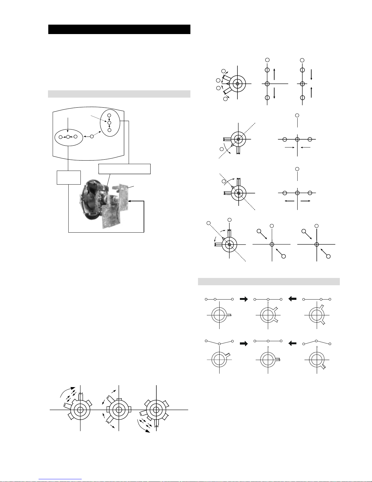
4. If the V.ST AT magnet is moved in the direction of the (a)
and (b) arrows, the Red, Green and Blue points move as
indicated below .
1. [Moving horizontally], adjust the H.ST AT control so that
the Red, Green and Blue points are on top of each other at
the centre of the screen.
2. [Moving vertically], adjust the V.ST AT magnet so that the
Red, Green and Blue points are on top of each other at the
centre of the screen.
3. If the H.STAT v ariable resistor is unable to bring the Red,
Green and Blue points together at the centre of the screen,
adjust the horizontal convergence with the H.STAT variable
resistor and the V.ST AT magnet in the manner indicated
below.
[In this case, the H.ST AT variable resistor and the V.ST AT
magnet influence each other].
The movement of the magnets interact with each other and so
the respective dot position should be monitored while carrying
out this adjustment.
Use the H.ST AT VR to adjust the Red, Green and Blue dots so
that they coincide at the centre of the screen
(by moving the dots in the horizontal direction).
GBR
GBR
GBR
G
B
R
GBR
G
B
R
3-2. Con vergence
Preparation:
• Before starting this adjustment, adjust the focus, horizontal
size and vertical size.
• Minimize the Brightness setting.
• Input a dot pattern from the pattern generator.
Horizontal and Vertical Static Convergence
Operation of the BMC (Hexapole) magnet.
Fig.3-5
• Tilt the V .STA T magnet and adjust the static con vergence by
opening or closing the V.ST AT magnet.
B
G
R
B
G
R
a
a
b
b
a
b
B
G
R
a
a
B
G
R
b
b
B
G
R
a
b
R
G
B
b
a
Center dot
R
G
B
R
G
B
C Board
RV702 (H STAT)
H STAT Convergence
(on mount side)
H STAT
convergence
control
V.STAT Vertical Static Magnet
 Loading...