

Sony KD-32DX40AS Service manual
SERVICE MANUAL
FE-2
CHASSIS
MODEL
COMMANDER DEST CHASSIS NO.
KD-32DX40AS
RM-933 AUS SCC-U78A-A
MODEL
COMMANDER DEST CHASSIS NO.
KD-32DX40AS
- 1 -
RM-933

TABLE OF CONTENTS
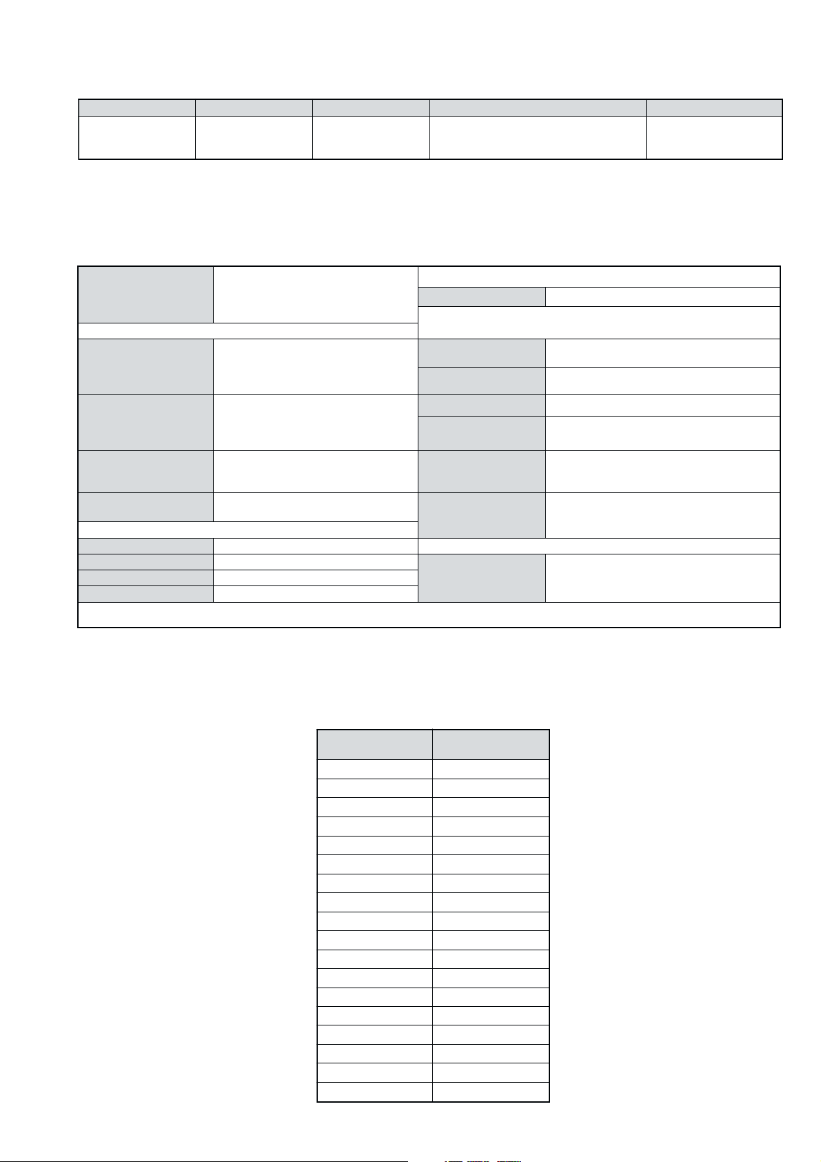
Section Title Page Section Title Page
Specifications .................... 3
Connectors .................... 4
Self Diagnostic Software .................... 5
1. GENERAL
Automatically Tuning the TV .................... 6
Watching a pre-recorded video tape ............. 6
Viewing Digital or Analogue Mode ............. 6
Selecting the Programme Index
Table (only for Analogue channels) ............. 6
Selecting the Channel Index
Menu (only for Digital channels) ............. 6
Viewing Teletext .................... 7
Selecting the Digital EPG Menu .............. 8
Selecting the Digital INFO Display ............. 9
The TV menu system .................... 9
The Picture Adjustment menu .................... 9
The Sound Adjustment menu .................... 9
The Timer Menu .................... 10
The Set Up Menu .................... 10
Accessing connected equipment
via the remote control .................... 11
Specifications .................... 12
Troubleshooting .................... 12
2. DISASSEMBLY
2-1. Rear Cover Removal .................... 13
2-2. Side Control Module Removal .................... 13
2-3. Chassis Removal .................... 13
2-4. Service Position .................... 14
2-5. F6 and H8 Board Removal .................... 14
2-6. N Board Removal .................... 14
2-7. Picture Tube Removal .................... 15
Bottom Plates .................... 16
3. SET-UP ADJUSTMENTS
5. DIAGRAMS
5-1. Block Diagrams (1) .................... 25
Block Diagrams (2) .................... 26
Block Diagrams (3) .................... 27
5-2. Circuit Board Location .................... 28
5-3. Schematic Diagrams and
Printed Wiring Boards .................... 28
* A Board Schematic .................... 29
* A Board PWB .................... 31
* B Board Schematic .................... 33
* B Board PWB .................... 32
* F6 Board Schematic .................... 33
* F6 Board PWB .................... 32
* H8 Board Schematic .................... 33
* H8 Board PWB .................... 32
* H2 Board Schematic .................... 33
* H2 Board PWB .................... 32
* VM Board Schematic .................... 34
* VM Board PWB .................... 35
* C Board Schematic .................... 36
* C Board PWB .................... 35
* D2 Board Schematic .................... 36
* D2 Board PWB .................... 35
* D3 Board Schematic .................... 36
* D3 Board PWB .................... 35
* F3 Board Schematic .................... 36
* F3 Board PWB .................... 35
* A1 Board Schematic .................... 37
* A1 Board PWB .................... 38
5-4. Semiconductors .................... 39
5-5. IC Blocks .................... 42
6. EXPLODED VIEWS
6-1. Chassis .................... 43
6-2. Picture Tube .................... 44
3-1. Beam Landing .................... 17
3-2. Convergence .................... 18
3-3. Focus Adjustment .................... 20
3-4. Screen (G2), White Balance .................... 20
4. CIRCUIT ADJUSTMENTS
4-1. Electrical Adjustments .................... 21
4-2. Test Mode 1 .................... 23
4-3. Test Mode 2 .................... 23
CAUTION
SHORT CIRCUIT THE ANODE OF THE PICTURE TUBE AND THE
ANODE CAP TO THE METAL CHASSIS, CRT SHIELD, OR THE
CARBON PAINTED ON THE CRT, AFTER REMOVAL OF THE
ANODE CAP.
AN ISOLATION TRANSFORMER SHOULD BE USED DURING
ANY SERVICE WORK TO AVOID POSSIBLE SHOCK HAZARD
DUE TO LIVE CHASSIS, THE CHASSIS OF THIS RECEIVER IS
DIRECTLY CONNECTED TO THE POWER LINE.
SAFETY-RELATED COMPONENT WARNING !!
COMPONENTS IDENTIFIED BY SHADING AND MARKED
THE SCHEMATIC DIAGRAMS, EXPLODED VIEWS AND IN THE
PARTS LIST ARE CRITICAL FOR SAFE OPERATION. REPLACE
THESE COMPONENTS WITH SONY PARTS WHOSE PART
NUMBERS APPEAR AS SHOWN IN THIS MANUAL OR IN
SUPPLEMENTS PUBLISHED BY SONY.
WARNING !!
£
ON
7. ELECTRICAL PARTS LIST .................... 45
ATTENTION
APRES AVOIR DECONNECTE LE CAP DE’LANODE,
COURT-CIRCUITER L’ANODE DU TUBE CATHODIQUE ET
CELUI DE L’ANODE DU CAP AU CHASSIS METALLIQUE DE
L’APPAREIL, OU AU COUCHE DE CARBONE PEINTE SUR LE
TUBE CATHODIQUE OU AU BLINDAGE DU TUBE
CATHODIQUE.
AFIN D’EVITER TOUT RISQUE D’ELECTROCUTION
PROVENANT D’UN CHÁSSIS SOUS TENTION, UN
TRANSFORMATEUR D’ISOLEMENT DOIT ETRE UTILISÈ LORS
DE TOUT DÈPANNAGE LE CHÁSSIS DE CE RÈCEPTEUR EST
DIRECTMENT RACCORDÈ Á L’ALIMENTATION SECTEUR.
ATTENTION AUX COMPOSANTS RELATIFS Á
LES COMPOSANTS IDENTIFIÈS PAR UNE TRAME ET PAR UNE
MARQUE
EXPLOSÈES ET LES LISTES DE PIECES SONT D’UNE IMPOR-
TANCE CRITIQUE POUR LA SÈCURITÈ DU FONCTIONNEMENT,
NE LES REMPLACER QUE PAR DES COMPSANTS SONY DONT
LE NUMÈRO DE PIÈCE EST INDIQUÈ DANS LE PRÈSENT
MANUEL OU DANS DES SUPPLÈMENTS PUBLIÈS PAR SONY.
£
SUR LES SCHÈMAS DE PRINCIPE, LES VUES
ATTENTION !!
LA SECURITÈ!!
- 2 -
LEDOMMETI metsySnoisiveleT metsySoeretS egarevoClennahC metsySroloC
SUAT-BVD,H/G/BoeretSNAMREG96E-82E:FHU21E-0E:FHVH/G/B
,34.4CSTN,LAP
)NIOEDIV(85.3CSTN
LM@PM2-GEPM
ebuTerutciP
skcaJonohPoiduArofelbairavsrotcennoCtuptuO
latigiD
kcajenohpdaeHkcajinimoerets
stupnioiduAskcajonohp
stupnioediVskcajonohp
tupnioediVSNIDnip4
nortinirTDFyalpsiDtalF
)sehcni23(mc28xorppA
)yllanogaid
]RAER[slanimreTtuptuO/tupnI
rotcennocoruEnip-12:1
)dradnatsCELENEC(
rotcennocoruEnip-12:2
slangiS
]EDIS[slanimreTtuptuO/tupnI
.BGRrofstupnI
.slangis
.oediVSrofstupnI
)elbatceles(
kcaJmedoM
AICMCP
derusaemerutcipmc67xorppA(
.slangisoediVdnaoiduArofstupnI
oiduAdnaoediVVTfostuptuO
.slangisoediVdnaoiduArofstupnI
.slangisoiduAdnaoediVVTfostuptuO
tuptuodnuoS
rekaepstfeLdnathgiR)SMR(W7x2)rewoPcisuM(W41x2
snoitacificepSlareneG
stnemeriuqeRrewoPV042-022
noitpmusnoCrewoPW431
snoisnemiDmm265x765x388xorppA
thgieWgk26xorppA
seirosseccAdeilppuS
serutaeFrehtO
stnemeriuqerrewoP
)1(rednammoCetomeR339-MR
)2(yrettab6RdetangisedCEI
txeteleT,noitcudeResioNotuA
,tnemtsujdAemuloVotuA,ybloDlautriV
ediuGmargorPcinortcelE
lortnoCderarfnI:metsySlortnoCetomeR
cdV3
noitangisedCEIseirettab2
)AAezis(6R
.ecitontuohtiwegnahcottcejbuserasnoitacificepsdnangiseD
metI
emaNledoM
bmoClaPFFO
PIPFFO
ytiroirPBGRNO
xoBrefooWFFO
1tracSNO
2tracSNO
)3(nitnorFNO
4tracSFFO
rotcejorPFFO
G/BmroNNO
ImroNFFO
K/DmroNFFO
SUAmroNNO
LmroNFFO
TASmroNFFO
MmroNFFO
txeteleTNO
oeretSmaciNFFO
SA04XD23-VK
- 3 -
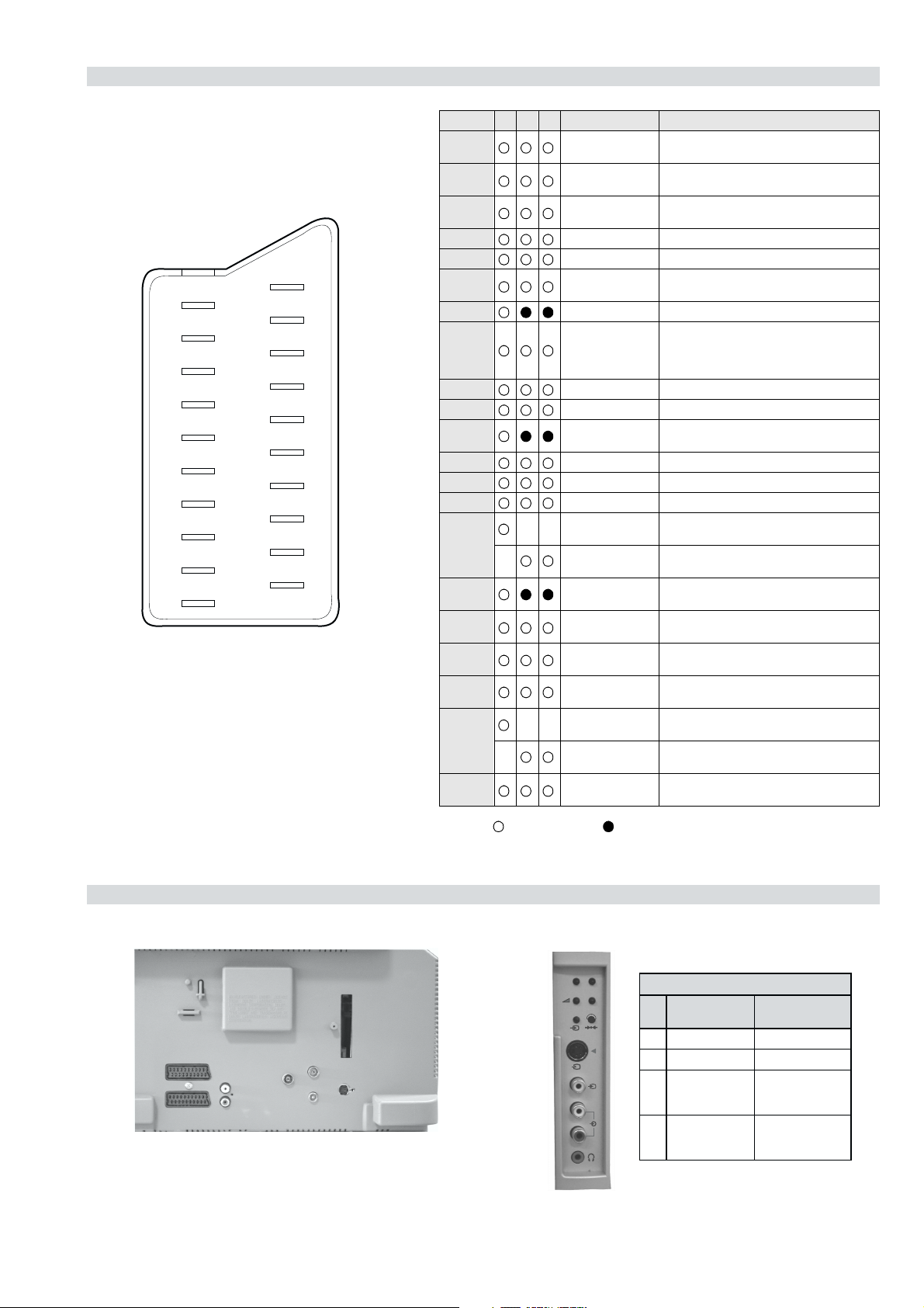
21 pin connector
21
19
17
15
13
11
9
7
5
3
1
20
18
16
14
12
10
4
2
Pin No 1 2 4 Signal Signal level
1 Audio output B
2
3
4 Ground (audio)
5 Ground (blue)
6 Audio input A
7 Blue input 0.7 +/- 3dB, 75 ohms positive
8 Function select
9 Ground (green)
10 Open
11 Green Green signal : 0.7 +/- 3dB, 75 ohms,
8
6
12 Open
13 Ground (red)
14 Ground (blanking)
15
_ (S signal Chroma
16 Blanking input
17 Ground (video
18 Ground (video
19 Video output 1V +/- 3dB, 75ohms, positive sync 0.3V
20
_ Video input
21 Common ground
(right)
Audio input B
(right)
Audio output A
(left)
(left)
(AV control)
_ _ Red input 0.7 +/- 3dB, 75 ohms, positive
input)
(Ys signal)
output)
input)
_ _ Video input 1V +/- 3dB, 75ohms, positive sync 0.3V
Y (S signal)
(plug, shield)
Standard level : 0.5V rms
Output impedence : Less than 1kohm*
Standard level : 0.5V rms
Output impedence : More than 10kohm*
Standard level : 0.5V rms
Output impedence : Less than 1kohm*
Standard level : 0.5V rms
Output impedence : More than 10kohm*
High state (9.5-12V) : Part mode
Low state (0-2V) : TV mode
Input impedence : More than 10K ohms
Input capacitance : Less than 2nF
positive
0.3 +/- 3dB, 75 ohms, positive
High state (1-3V) Low state (0-0.4V)
Input impedence : 75 ohms
(-3+10dB)
(-3+10dB)
1V +/- 3dB, 75ohms, positive sync 0.3V
(-3+10dB)
Connected Not Connected (open) * at 20Hz - 20kHz
Rear Connection Panel Side Connection Panel
p
- +
niP
oN
S-Video
socket
s
4
4
MONO
L/G/S/I
4
R/D/D/D
1dnuorG-
2dnuorG-
3tupni)langisS(Y,mho57Bd3-/+V1
4tupni)langisS(CBd3-/+V3.0
langiS leveLlangiS
noitarugifnocniptekcosoediVS
V3.0.cnySevitisop
Bd01+3-
evitisop,mho57
.cnyS
- 4 -
FE-2 SELF DIAGNOSTIC SOFTWARE
The identification of errors within the FE-2 chassis is triggered in one of two ways :- 1: Busy or 2: Device failure to respond to IIC. In the event
of one of these situations arising the software will first try to release the bus if busy (Failure to do so will report with a continuous flashing
LED) and then communicate with each device in turn to establish if a device is faulty. If a device is found to be faulty the relevant device number
will be displayed through the LED (Series of flashes which must be counted) See table 1., non fatal errors are reported using this method.
Each time the software detects an error it is stored within the NVM. See Table 2.
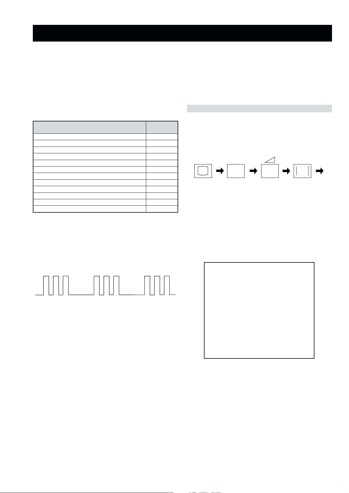
Table 1
egasseMrorrE
rorreoN00
devreseR10
)noitcetorPtnerruCrevO(PCO20
desUtoN30
cnySlacitreVoN40
norewoptarorrERKI50
norewoptawolsenilatadro/dnakcolcsubCII60
norewoptaegdelwonkcasubCIIonMVN70
desUtoN80
norewoptaegdelwonkcaonrenuT90
rorrErossecorPdnuoS01
rorrestlov8rellortnocelgnuJ11
Flash Timing Example : e.g. error number 3
StBy LED
ON
ON ON
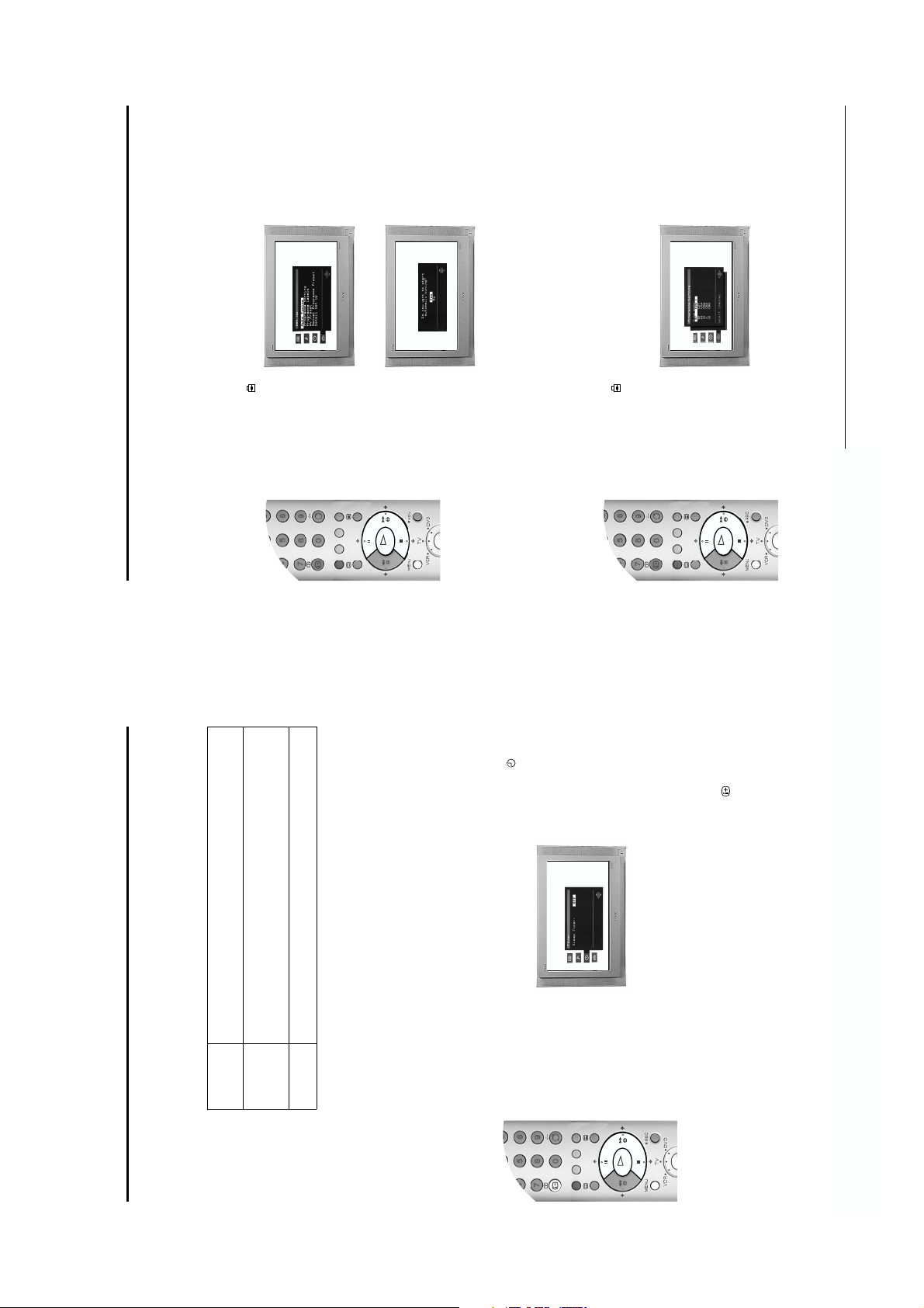
How to enter into Table 2
DEL
edoC
1. Turn on the main power switch of the TV set and enter into
the ‘Stanby Mode’.
2. Press the following sequence of buttons on the Remote
Commander.
i+
(ON SCREEN (DIGIT 5) (VOLUME -) (TV)
DISPLAY)
5
-
3. The following table will be displayed indicating the error
count.
Table 2
UNEMRORRE
OFF
OFF
20E
30E
40E
50E
60E
70E
80E
90E
01E
11E
SRUOH
SETUNIM
PCO
A/NPVO
CNYSV
RKI
CII
MVN
ELGNUJ
RENUT
PDNUOS
V8
EMITGNIKROW
)552,0(
0
)552,0(
0
)552,0(
0
)552,0(
0
)552,0(
0
)552,0(
0
)552,0(
0
)552,0(
0
)552,0(
0
)552,0(
0
2
11
Note: To clear the error count data press ‘80’ on the Remote
commander.
- 5 -
O
K
O
K
OK
VIDEO
/
TV
/
DIGITAL
SECTION 1 GENERAL
7
Basic Operation
of programmes,
*1
(only for Analogue channels)
(only for Digital channels)
where transmitted
*1
a) View a complete list of the programmes available for selection,
b) Obtain a preview of the programmes contained in the list,
c) Search for a programme quickly by selecting from different categories
d) Store programmes into a list of favourites.
1. Press the OK button to display the ‘Programme Index table’ on screen.
‘Programme Index table’ is on ly available in analogue mode.
Press the DIGITAL/ button on the remote control to switch between Digital and analogue mode. To
check if you are watching a Digital or analogue mode press the PROG +/- button. If you are watching a
digital programme a banner appears momentarily at the top of the screen.
Viewing Digital or analogue mode
The ‘Programme Index table’ is a quick and easy way to search for a channel you wish to view. The
Selecting the Programme Index table
2. Press the V or v button to scroll through the list until the channel you wish to view is highlighted.
3. Press the OK button to display your chosen channel on the TV screen.
The ‘Channel Index menu’ provides you with a quick and easy way to:-
Selecting the Channel Index menu
menu contains a list of all the available channels. The name of the programme currently being shown
along with its start and finish times is shown for each of the available channels. The current channel is
previewed in the top right corner of the screen with its channel name and number displayed below it.
programme. If you do not want to select a programme from the 6 channels listed, press the GREEN
The ‘Channel Index menu’ is only available in Digital mode.
1. Press the OK button on the remote control to display the ‘Channel Index menu’ on the TV screen. The
button to display the next 6 programmes or the RED button to display the preceding 6 channels.
2. Press the V or v buttons to move the coloured cursor up or down the li st to select the desired
3. Press the OK button to display the highlighted programme in the preview window*.
to enter your PIN code before the preview is displayed. Refer to ‘The Main Menu’ for more information on the
‘PIN Code’ feature. Programmes that exceed the Parental Rating you set are identified with a symbol.
be displayed.
Note: If a Parental Rating for viewing has been set and the programme selected exceeds that rating, you will need
4. Press the OK button to exit the ‘Channel Index menu’. The programme that was being previewed will
as in the manual.
The operating instructions mentioned here are partial abstracts from the ‘Operating
Instruction Manual’. The page numbers of the ‘Operating Instruction Manual’ remain
Getting Started
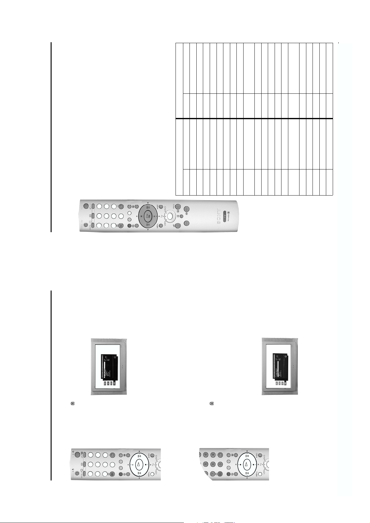
5. Automatically tuning the TV
OK
Adjust now
Not necessary
If picture slants, please
adjust picture rotation.
Checking the picture tilt.
screen asking you to check if the picture is slanted. (Sometimes the
Earth’s natural magnetism can cause the screen to look tilted.)
The autotune prompt screen.
remote control to highlight ‘Adjust now’, then press the OK button.
control to highlight ‘Not necessary’ and press the OK button.
Correct the slant by pressing the V or v buttons then pr ess the
OK button to store.
b) If some correction is required, press the V or v buttons on the
a) If no correction is required, press the V or v buttons on the remote
1. When you switch on the TV for the first time a menu appears on the
/
3
6
TV
VIDEO
/
DIGITAL
9
2
5
8
4
1
7
The ‘Region Set-up screen.
buttons to highlight your chosen region then press the OK button to
‘Ye s ’.
2. The autotune prompt screen appears. Press the OK button to select
0
confirm.
3. The ‘Region Set-up’ menu appears on screen. Press the V or v
K
O
4. The Digital autotune display appears on screen and the search and
Tuning the Digital channels.
store procedure begins. All the available Digital channels will now be
captured and stored. As this may take some time, a message is
included in the display to inform you of the tuning progress.
When Digital tuning is complete, the analogue display appears
automatically and the search and store procedure for the analogue
channels begins.
If no Digital and no analogue channels are found, a menu appears
asking you to confirm your aerial is connected. After checking the
Tuning the analogue channels.
aerial has been connected press OK to begin the autotune
C29
Programme: 02
Channel :
Completed 16%
Auto Tuning
control until the picture from the pre-recorded video tape appears on the TV screen.
If you wish to move your video channel to a different channel number, refer to the
procedure again.
Once all Digital and analogue channels have been captured and
channel number 1 is displayed.
stored, the TV returns to normal operation and displays the Digital
channel captured on channel number 1.
buttons.
Note: If no Digital channels are captured, the analogue channel that is stored on
5. To view programmes, press the PROG+/- buttons or the num bered
6. Watching a pre-recorded video tape
aerial and a VCR’ section. To view the video picture pre ss ‘PLAY’ on the VCR.
The TV automatically displays the video picture (providing that you have used a
fully wired 21 pin scart lead to connect your VCR to the TV).
If the video picture does not automatically appear, press the / button on the
1. You should have inserted a pre-recorded video tape during the ‘Connecting an
the remote control repeatedly until the video picture is displayed on the TV screen.
Note: If the video picture does not automatically appear, and your VCR is connected via one of the AV sockets, press the / button on
remote control repeatedly until the video picture is displayed on the TV screen.
2. Press the DIGITAL/ button on the remote control to return to normal TV
‘Programme Sorting’ feature in ‘The Set Up menu’ section of this instruction manual.
mode.
Note: Alternatively, with the TV in analogue mode, press the PROG +/- buttons on the remote
4
- 6 -
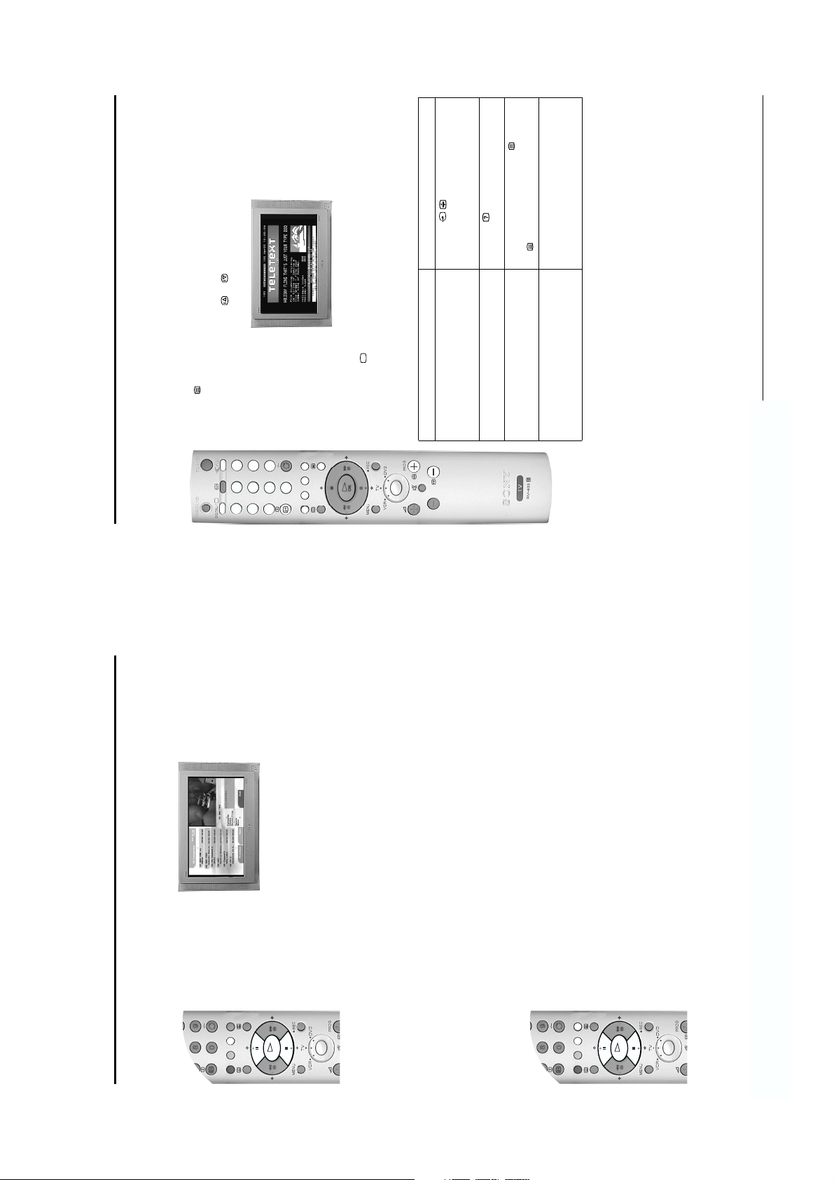
Most TV channels broadcast a text service. The index page (usually page 100) provides information on
how to use the service. Please ensure you are receiving a good signal, or some text errors may occur.
Switching Teletext on and off
Basic Operation
Viewing Teletext
VIDEO
Press the / button to hold the page
currently being displayed. Press again to cancel.
Press the button to reveal the hidden
information. Press again to cancel.
In Teletext mode, press the button to
superimpose Teletext on to the TV screen. Press
the button again to exit Teletext.
Press the corresponding coloured button on the
remote control to access the required page.
Feature How to use
follow on automatically. This feature
allows you to hold the current page
until you are ready to proceed.
information (e.g. for a quiz).
superimpose Telet ext on to the TV
screen.
quickly and easily. Wh en Fastext is
available, four coloured items appear
at the bottom of the screen.
wish to view. Alternatively, press the or buttons to view the previous page or next page. After
a short time your selected page appears on screen.
1. Press the button on the remote control to enter Teletext mode.
2. Using the numbered buttons on the remote control, enter the three digits of the page number you
/
3
6
TV
/
DIGITAL
9
2
5
8
0
4
1
7
3. Enter more 3 digit page numbers as required.
4. Press the DIGITAL/ button to exit Teletext.
How to use Teletext features
Hold Some pages contain sub-pages which
Reveal Some Teletext pages contain hidden
Mix This feature allow s you to
Fastext Fastext allows you to access pages
10
Basic Operation
News Contains all news channels.*
Film Contains all film channels.*
Entertainment Contains all entertainment channels.*
Lifestyle Contains all lifestyle channels.*
Education Contains all education channels.*
Kids Contains all children’s channels.*
Radio Service Contains all radio services
selected.
The following categories are available:
Favourite Co ntains all the progr ammes you have stored as a favourite (see below).
Choice The TV creates this list based on the type of programmes you watch the most.
Recent Prog. Contains the last 5 programmes watched.
All Categories Contains all available channels.
The Category pop-up list
up list.
The ‘Category’ pop-up list allows you to quickly search for a programme by choosing from different
categories of programmes.
1. With the ‘Channel Index menu’ on screen, press the YELLOW button to display the ‘Category’ pop-
displayed in a title bar at the top of the programme list along with the date and time.
3. Press the OK button. The ‘Channel Index menu’ will now contain only programmes of the type
2. Press the V or v buttons to hi ghlight the requir ed category. The categor y you choose will be
K
O
Sports Contains all sport channels.*
*Available when category information is transmitted
Favourite programmes
This feature allows you to create a list of your favourite programmes.
To add a programme to the Favourite list
want as a favourite.
1. With the ‘Channel Index menu’ on screen, press the V or v buttons to highlight the programme you
2. Press the BLUE button to store the programme in the favourite list.
up list.
To remove a programme from the Favourite list
1. With the ‘Channel Index menu’ on screen, press the YELLOW button to access the ‘Category’ pop-
2. Highlight the ‘Favourite’ category. Press the OK button to display the ‘Favourite list’.
3. Highlight the programme you wish to remove from the ‘Favourite list’.
4. Press the BLUE button to remove the programme.
K
O
8
- 7 -
VIDEO
/
TV
/
DIGITAL
menu that you wish to record, then press the OK button. The Timer screen appears.
O
K
To select a programme for recording or timed display
1. With the EPG menu on screen, press the V, v, B or b buttons to highlight a progra mme in the EPG
store the programme settings on the TV, then set the timer recording function on your VCR to correspond with
the programme you have stored for recording.
When a programme has been stored for recording, a solid bar appears in the EPG display directly under the
timer bar. This solid bar shows you the amount of time allocated to a recording, and reminds you that you are
(only if your VCR has Smartlink facility), or press the GREEN button if you wish the programme to
appear on your TV screen when transmission begins.
2. Press the RED button and your VCR will automatically record the selected programme when it starts
Notes: If you do not have a Smartlink VCR, a message appears on screen to inform you. Press the RED button to
unable to record any other programmes during that period of time.
does not have Smartlink a message will be displayed reminding you to set your VCR timer. Press the
RED button to display the ‘Manual Ti mer Record’ menu.
To set the Manual Timer
1. With the EPG menu on screen, press the BLUE button to display the Timer List menu. If your VCR
3. Press the V or v buttons to select the start time. Press the b button to highlight the stop time.
2. Press the V or v buttons to select the correct date. Press the b button to highlight the start time.
K
O
menu is displayed. The event is now set to the Timer List. Press the YELLOW button to delete the
timed event or press the BLUE button to return to the main EPG screen.
4. Press the V or v buttons to select the stop time. Press the b button to highlight the programme.
6. Press the RED button and repeat steps 2 to 5 if you wish to store further programmes for recording.
5. Press the V or v buttons to select the programme. Pres s the OK button to store. Th e Timer List
programmes you have stored for recording.
7. Press the button to return to normal TV operation.
8. Set the timer recording function on your VCR to switch on and off to correspond with the
Note: Once a programme has started recording, do not switch channels or the r ecording will be cancelled.
To cancel a previously set event
3. Press the YELLOW button to cancel the programme/event.
1. With the EPG menu on screen, press the BLUE button to display the Timer List.
2. Press the V, v, B or b buttons to highlight the programme/event you wish to cancel.
Basic Operation
Basic Operation
12
11
a) View a complete list of the programmes available.
b) Obtain a preview of the programmes currently being broadcast.
c) Reduce the size of the list by selecting a category of programme, e.g. Sports or Movies.
d) Record programmes.
the information was being transmitted.
mode, press the DIGITAL/ button on the remote control. Press the button on the remote
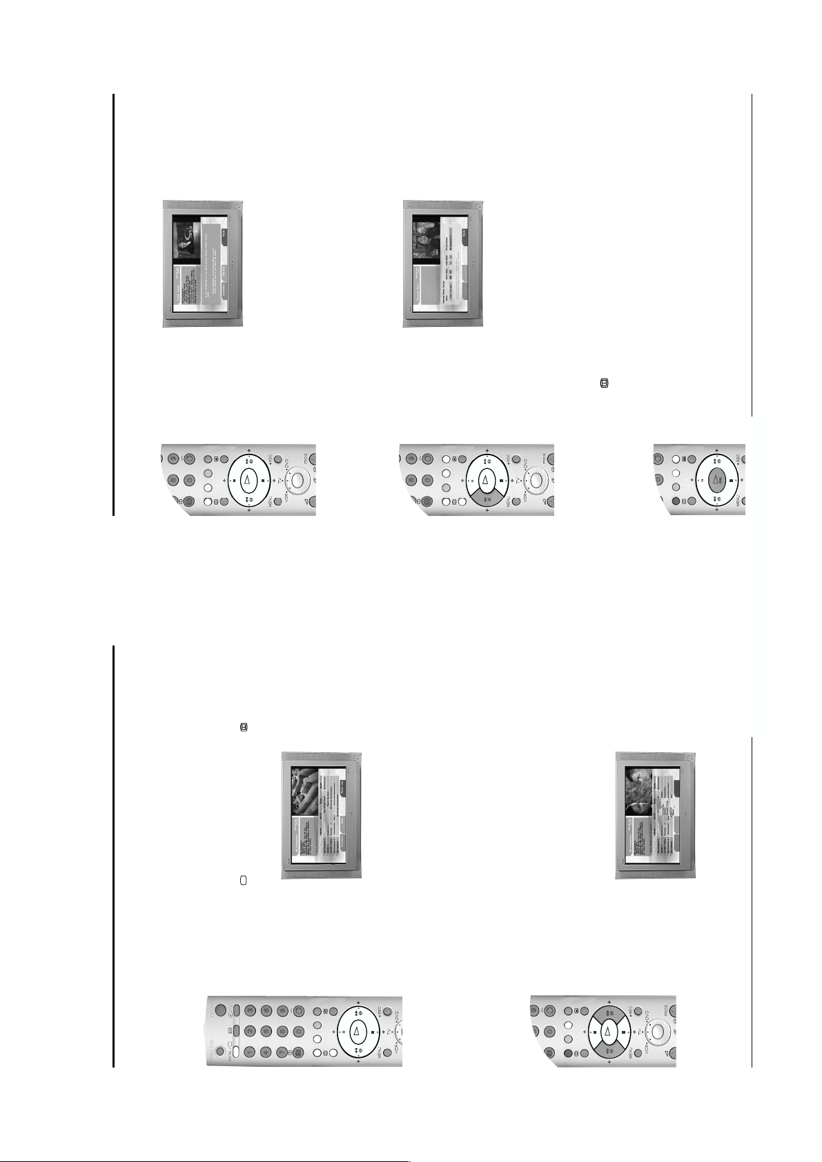
control to display the EPG menu screen. This screen consists of an information window, a preview
window, a 2 hour timer bar (divided into 30 minute intervals) and a 5 channel programme list
The EPG menu (Electronic Programme Guide) provides you with a quick and easy way to:-
Note* EPG information will only be displayed if the TV station is transmitting it and you have viewed that station while
covering the 2 hour period.
1. The EPG menu is only available when watching Digital channels. If the TV is not already in Digital
programme on the right, the programmes scheduled for the next 2 hour period are displayed. As
each programme is highlighted, a brief description of the programme appears in the event
information box at the top left of the screen. If you do not wish to select a programme from the 5
channels listed, press the GREEN button to display the next 5 channels or RED button to display the
previous 5 channels.
the preview window. If you have previously set a Parental rating in the ‘Digital Setting’ menu, and the
programme exceeds that rating, you will be asked to enter your PIN code before the preview is
allowed.
B buttons to move left or right. If you press the b button once more after highlighting the last
2. Press the V or v buttons to move the coloured cursor bar up or down the programme list and the b or
K
O
3. If a programme you highlight is currently being broadcast, press the OK button to obtain a preview in
the EPG menu and view the programme at full size.
The Category pop-up list
The ‘Category’ pop-up list allows you to quickly search for a programme by choosing from different
categories of programmes. For example, select the ‘News’ option from the ‘Category’ pop-up list to
4. When the programme in the preview screen is the one you wish to watch, press the OK button to exit
display programme information only for News channels.
programme list will now only contain programmes of the type selected.
For information on the types of Categories along with instructions on how to add and remove programmes
1. With the EPG menu on screen, press the YELLOW button to display the ‘Category’ pop-up list.
2. Press the V or v buttons to highlight the category you want, then press the OK button. The EPG
K
O
from the Favourite list, please refer to ‘The Channel Index menu’ section of this instruction manual.
Selecting the Digital EPG menu
- 8 -
This TV contains a menu system which is based on a series of user friendly on-screen displays. These
OKO
K
displays will help you to get the most from your TV, helping you to change the picture settings, sound
continued...
menu to suit your personal preference.
to suit your personal preference.
button to store the new setting and repeat step 2 to adjust the other options.
The Mode option has three settings for you to choose from:-
Perso nal: This setting allows you to adjust the Brightness, Colour, Contrast and Sharpness* levels
Live: This is a fixed setting and is recommended for live broadcasts.
Adjustment’ menu.
1. Press the MENU button to display the main menu, then press the b button to enter the ‘Picture
settings and change the order of the TV channels.
b button to activate the option, press b and B or V or v buttons to adjust the setting. Press t he OK
2. ‘Mode:’ is highlighted. Press the V or v button to highlight one of the options, then after pressing the
Movie: This is a fixed setting and is recommended for watching films.
*Sharpness is adjustable in analogue mode only.
3. Press the MENU button to return to normal TV operation.
Notes: Highlight Reset and press OK only if you wish to return the picture to the factory preset levels.
Now press the b button to enter the ‘Sound Adjustment’ menu.
1. Press the MENU button to display the main menu, then press the v button to highlight the symbol.
b button to activate the option press b and B or V or v buttons to adjust the setting.
2. ‘Mode:’ is highlighted. Press the V or v button to highlight one of the options, then after pressing the
Personal: This setting allows you to adjust all the available options in the ‘Sound adjustment’
Rock: This is a fixed setting and is recommended for rock soundtracks.
Pop: This is a fixed setting and is recommended for pop soundtracks.
The Mode option has four settings for you to choose from:-
3. Press the OK button to store the new setting and repeat step 2 to adjust the other options.
Jazz: This is a fixed setting and is recommended for jazz soundtracks.
Note: ‘Treble’ and ‘Bass’ settings can only be altered when the ‘Mode’ option is set to Personal.
menu. This menu gives you a further three options to choose from.
4. When ‘Detail Adjustment’ is highlighted, press the b button to display the ‘Detail Adjustment’ sub
Advanced Operation
The TV menu system
Basic Operation
The Picture Adjustment menu
The Sound Adjustment menu
18
13
/
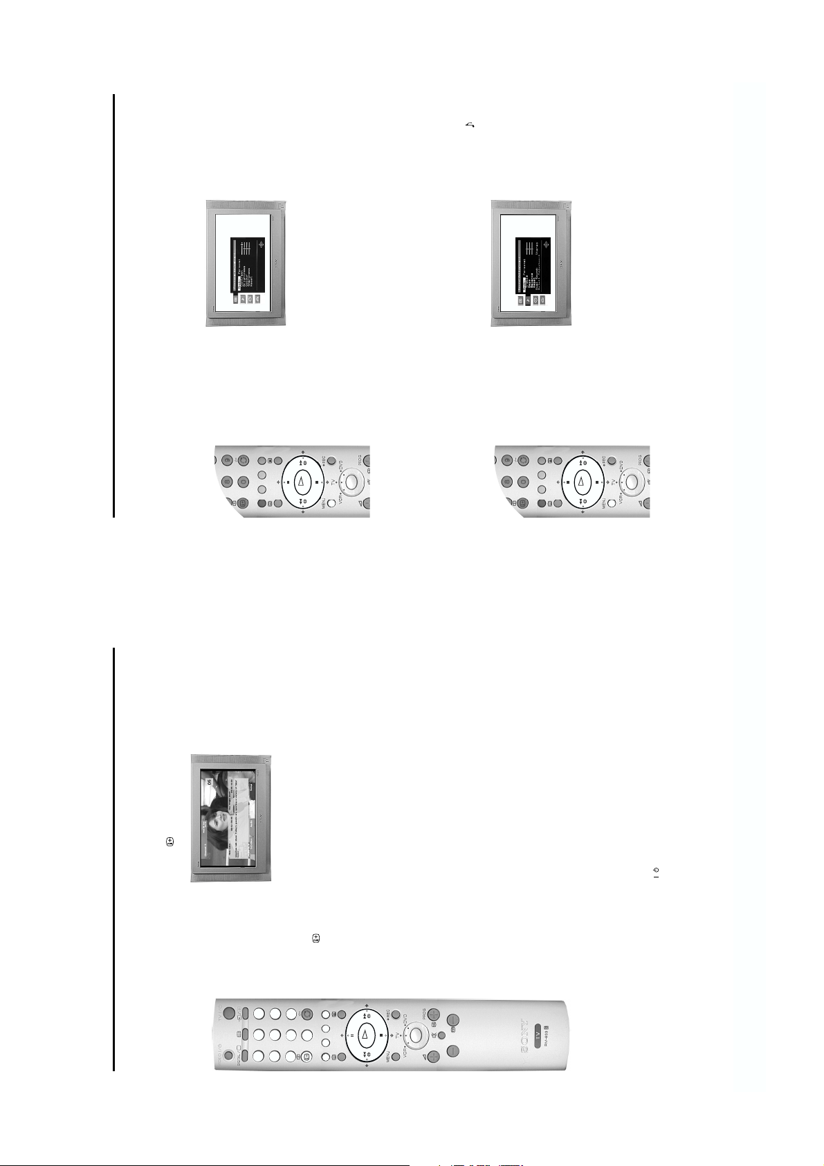
display’ screen.
This menu gives you information both for programmes currently being shown and for future programmes
on the channel you are currently viewing.
1. With the TV in Digital mode, press the button on the remote control to display the ‘Digital INFO
/
TV
/
VIDEO
Selecting the Digital INFO display
DIGITAL
programme box is blank, there is no information currently available. To return to the starting point,
press the B button repeatedly until the description for the current programme reappears.
2. Press the b button to obtain a brief d escription of the next programme in the schedul e. If the
3
6
9
2
5
8
4
1
7
remote control.
language required then press OK to select. To remove subtitles from the TV screen, access the ‘Subtitles’
3. Press the button on the remote control at any time to exit the ‘Digital INFO display’.
Note: To change channels while the ‘Digital INFO display’ is on screen, press the relevant numbered buttons on the
Using other INFO menu features
0
K
O
Subtitles (where available. Also refer to ‘Viewing Digital Teletext’)
This feature will place Digital subtitles on the screen. With the ‘Digital INFO display’ on the TV screen,
press the RED button to access the ‘Subtitles’ pop-up menu. Press the V or v button to highlight the
pop-up menu and select ‘Off’.
on the TV screen, press the GREEN button to access the ‘Audio’ pop-up menu. Press the V or v button
to highlight the language required then press OK to select.
Audio
This feature allows you to listen to the broadcast in different languages”. With the ‘Digital INFO display’
Note: *Only when the programme is broadcast in multiple languages.
REC/Timer
If you highlight a current programme, the REC feature allows you to automatically set your VCR to record
the selected programme**.
With the ‘Digital INFO display’ on the TV screen, press the YELLOW button to access the ‘REC’ pop-up
menu. If your VCR does not have Smartlink a message is displayed reminding you to manually set your
VCR. Press the RED button to continue or press the BLUE button to return to the INFO display.
If you highlight a future programme, the Timer feature allows you to automatically set your VCR to record
the selected programme, or have the TV switch to the correct channel automatically when the selected
programme starts.
Press the RED button and your VCR will automatically record the selected programme when it starts (only
if your VCR has Smartlink facility), or press the GREEN button if you wish the programme to appear on
your TV screen when transmission begins.
Do not switch off theTV once a programme has been set to record. If you do not wish to view the programme
being recorded, press the TV button on the remote control to switch the TV into standby mode.
When a programme has been set to record and the TV is in standby mode the standby indicator on the front
of the TV will flash green periodically to inform you that a programme has been set to record.
Do not change channels or switch the TV to analogue mode once a programme has started recording or the
recording will be cancelled.
Notes: **Only for Smartlink VCRs
Set-up
With the ‘Digital INFO display’ on the TV screen, press the BLUE button labelled set-up to access the
‘Main Menu’. The ‘Main Men u’ is explained on the following pages.
- 9 -
O
K
The ‘Set Up’ menu contains many features that enable you to customise your TV. The following pages
OKO
K
OK button.
button.
explain all of the features contained in the ‘Set Up’ menu.
The TV automatically tuned in all the available channels when you first installed the TV. Follow these
button to highlight the symbol, then press the b button to enter the ‘Set Up’ menu.
instructions if you wish to re-install your TV at an alternative location or search for new channels that have
been subsequently launched by broadcasters.
1. With the TV in analogue mode, press the MENU button to display the main menu. Press the V or v
prompt display appears on screen.
2. Press the V or v buttons to highli ght ‘Auto Tuning ’ then press the b button to confirm. The autotune
Whilst tuning is taking place, the search and store display appears on screen.
When all available signals have been captured and stored, the display is removed and the TV returns
to normal operat ion.
3. Press the OK button to select ‘Yes ’ and begin the autotune procedure.
Notes: You can cancel the tuning at any time by pressing the MENU button.
You can use this feature to change the order in which the analogue channels are stored on your TV.
Programme Sort ing menu on screen.
button to highlight the symbol, then press the b button to enter the ‘Set Up’ menu.
1. With the TV in analogue mode, press the MENU button to display the main menu. Press the V or v
2. Press the V or v buttons to highlight ‘Programme Sorting’ then press the b button to display the
3. Press the V or v button to highlight the channel you wish to move to a new position, then press the
normal TV operation.
4. Press the V or v button to highlight the new channel number for your channel, then press the OK
5. Repeat steps 3 and 4 to move other channels if required, then press the MENU button to return to
Advanced Operation
Advanced Operation
The Set Up menu
Auto Tuning
‘Dolby Virtual’ will automatically be set to Off.
Programme Sorting
20
19
5. Highlight and activate one of the options using the v and b buttons, then press the V or v buttons to
Note: If you connect headphones to this TV or if you set the ‘Au to Volum e’ option to ‘On’,
set the option to On or Off. See the table below for an explanation of each option and their effects.
Dolby* Virtual When set to ‘On’, the TV simulates the effects of Dolby Pro Logic Surround sound.
6. Press the OK button to store the new setting, then repeat step 5 to alter the other options.
7. Press MENU button to return to normal TV operation.
Note: This option automatically sets itself to ‘Off’ when ‘Dolby Virtual’ is set to ‘On’.
should change, i.e. during commercial breaks.
Auto Volume When set to ‘On’, the volume level will remain constant even if the broadcast level
the rear of the TV.
TV Speakers Set to ‘Off’ if you wish to connect an external amplifier to the audio output sockets on
• Notes on the Sound Adjustment menu
• Highlight ‘Reset’ and press OK only if you wish to return the sound settings to their factory preset levels.
Sound’ option can be set to Stereo or Mono.
sound or ‘Mono’ if the mono channel is available for selection. When receiving a stereo broadcast the ‘Dual
• When receiving a bilingual broadcast set the ‘Dual Sound’ option to ‘A’ for channel 1 sound, ‘B’ for channel 2
broadcast without the need for additional speakers. However, you can connect an external amplifier to this TV if
desired (see ‘Connecting additional equipment’ section of this manual).
of Dolby Laboratories.
* This TV has been designed to create a Virtual Dolby Surround sound effect from a ‘Dolby Pro Logic Surround’
* Manufactured under licence from Dolby Laboratories. ‘Dolby’, ‘Pro Logic’ and the double-D symbol are trademar ks
Press the b button twice to highlight ‘Off’ in the ‘SleepTimer’ menu.
The ‘Sleep Timer’ allows you to select a period of time after which the TV automatically switches itself
into standby mode.
1. Press the MENU button to display the main menu. Use the V or v button to highlight the symbol.
can be in 15 minute intervals up to a maximum of 4 hours.
3. Press the OK button to store.
2. Press the V or v buttons to set the amount of time before the TV switches itself into standby. This
4. Press the MENU button to return to normal TV operation. One minute before the TV switches into
remaining is displayed in the bottom left corner of the TV screen.
standby, the time remaining is counted down on screen.
Note: In analogue mode you can check the time remaining until standby by pressing the button. The time
The Timer menu
- 10 -
VIDEO
/
TV
/
DIGITAL
O
K
1
2
3
6
5
4
7
8
9
0
O
K
LOEWE 009, 028, 023, 024, 016, 003
SAMSUNG 011, 014
Additional Information
Accessing connected equipment via the remote control
358, 359
ORION 328 PHILIPS 009, 028, 023, 024, 016, 003
PHILIPS 311, 312, 313, 316, 317, 318,
PANASONIC 321, 323 PIONEER 004
SAMSUNG 339, 340, 341, 345 SANYO 007
SHARP 324 THOMSON 012
SANYO 335, 336 SHARP 019, 027
THOMSON 319, 350 TOSHIBA 003
TOSHIBA 337 YAMAHA 018, 027, 020, 002
28
GRUNDIG 358, 355, 360, 361, 320, 351 KENWOOD 008
354, 348, 349
LG 332, 338 MATSUI 013, 016
JVC 314, 315, 322, 344, 352, 353,
LOEWE 358, 355, 360, 361, 320, 351 ONKYO 022
HITACHI 327, 333, 334 LG 015, 014
MATSUI 356, 357 PANASONIC 018, 027, 020, 002
VCR Brand List DVD Brand List
the above procedure to re-enter the code. A small label has been attached to the inside of the battery cover
for you to make a note of your brand codes. Not all brands and models of DVDs or VCRs are covered in this
list, however, Sony will endeavour to update the software periodically. Please refer to the code table provided
OR the green DVD light is illuminated.
approximately 6 seconds, until the light starts to flash.
been entered, all three green lights will illuminate momentarily.
repeat steps 2 - 4 and enter the next 3 digit code allocated to your brand of VCR or DVD.
until the TV green light illuminates. Don’t forget to select VCR or DVD using the Media Select button
This remote control can operate not only Sony DVDs and VCRs, but also those made by other
manufacturers. The following instructions will guide you through the set up procedure.
1. Find the 3 digit code for your brand from the list below.
2. Press the Media Select button on the remote control until either the green VCR light is illuminated
3. Whilst the required green light is illuminated, press and hold down the YELLOW button for
4. Use the numbered buttons to enter the 3 digit code for your DVD or VCR. Once a correct number has
5. Turn on your DVD or VCR and check that the remote control operates the main functions. If not,
/
3
6
9
2
5
8
0
4
1
7
VIDEO
TV
/
DIGITAL
every time you wish to operate that equipment with this remote control.
6. When you wish to use the remote control to operate the TV again, press the Media Select button
with your remote control.
Note: The brand codes you set may be lost if weak batteries are not replaced immediately. Should this happen, use
Brand Code Brand Code
SONY (VHS) 301, 302, 303, 309 SONY 001
SONY (BETA) 303, 307 , 310 AIWA 021
AKAI 326, 329, 330 HITACHI 025, 026, 015, 004
AIWA 325, 331, 351 GRUNDIG 009, 028, 023, 024, 016, 003
SONY (DVD) 304, 305, 306 DENON 018, 027, 020, 002
DAEWOO 342, 343 JVC 006, 017
until the broadcast appears. Press the OK button twice to store.
want or your VCR’s channel number. If you do not know the channel number, press V or v buttons
normal TV operation.
5. Repeat steps 3 and 4 to select and store other channels, then press the MENU button to return to
This feature allows you to name an analogue channel using up to 5 characters (letters or numbers).
button to highlight the symbol, then press the b button to enter the ‘Set Up’ menu.
1. With the TV in analogue mode, press the MENU button to display the main menu. Press the V or v
buttons until the chann el number you wish to name a ppears.
the ‘Manual Programme Preset me nu’ on screen.
3. ‘Programme:’ is highlighted. Press b button to highlight th e channel number, then pres s the V or v
2. Press the V or v buttons to highlight ‘Manual Programme Preset’ then press the b button to display
Naming a channel
- 11 -
channel number, then using the numbered buttons, enter the channel number of the broadcast you
V buttons until your new channel number for your channel appears on screen (if you are tuning in a
button to highlight the symbol, then press the b button to enter the ‘Set Up’ menu.
This feature allows you to manually add analogue channels one by one to your TV.
Advanced Operation
Manual tuning
the ‘Manual Programme Preset’ m enu on screen.
1. With the TV in analogue mode, press the MENU button to display the main menu. Press the V or v
2. Press the V or v buttons to highlight ‘Manual Programme Preset’ then press the b button to display
VCR please select pr ogramme number ‘0’).
4. Press the B button, then press v button to highlight ‘Channel’. Press b button to highlight existing
3. ‘Programme:’ is highlighted. Press b button to highlight the programme number, then press the v or
Select the remaining letters or characters this way, then press the OK button twice to store.
then press the V or v buttons until the first letter or character you desire appears (select ‘-’ to insert
a blank space). Press b button to confirm your choice.
4. Press the B button, then press v button to highlight ‘Label’. Press b button to enter label column,
K
K
O
O
operation.
5. Repeat steps 3 and 4 to name other channels, then press MENU button to return to normal TV
22
/
Additional Information
• Power off.
• TV in standby.
Problem Cause
Troubleshooting
No picture, no sound.
Here are some simple soloutions to problems which may affect the picture and sound.
currently using.
• Aerial disconnected.
• Picture preset level adjus tment.
• No digital transmissions in your area.
• No digital transmissions from the transmitter you are
• Weak signal.
• Unsuitable aerial.
• Scrambled/subscription-only channel.
• Programme used only for data (no picture or sound).
• Programme not being transmitted.
• Digital mode Timer Record active (regular flash).
• Fault (irregular flash).
Poor or no picture (screen is dark), but good sound.
No Digital channels after tuning.
Some channels are blank.
Standby indicator flashing.
video source.
• Volume control.
• TV speakers turned off.
• Headphones are connected.
• Wrong external mode selected on an YUV/component
• Colour level setting.
• Batteries low.
• Media Selector set to wrong mode for the equipment in use.
• Inputs from external equipment not switched off.
Good Picture, no sound.
Poor picture quality.
No colour on colour programmes.
Remote control does not function.
Distorted picture when changing programmes or selecting
Teletext.
Cause Solution
button on the remote control.
brightness, picture and colour balance levels.
transmissions begin in your area.
should be pointing your aerial.
programmes. (Contact a local installer)
• Plug in the TV.
• Press the button on the front of the TV.
• If the indicator is on press the button or a numbered
• Check the aerial connection.
• Select on the TV me nu system then adj ust the
• Contact a local installer to find out when digital
• Contact a local installer to find out at which transmitter you
TV in standby.
Aerial disconnected.
Picture level adjustment.
No Digital transmissions in your area.
No Digital transmissions from the transmitter you are
currently using.
other equipment).
• Change your aerial to cover the channels used by digital
• Ensure aerial is correctly aligned to transmitter.
• Ensure aerial is plugged directly into the TV (not through
• Upgrade to a higher gain aerial.
• Subscribe to pay-per-view broadcaster.
• See ‘Skipping a programme’ section of this manual.
• See ‘Programme Sorting’ section of this manual.
• Do not open the cabinet, refer to qualified personnel.
Unsuitable aerial.
Weak signal.
Scrambled/subscription-only channel.
Programme information without picture or sound.
Fault.
remote control.
symbol is displayed on screen.
• Contact your nearest Sony Service Centre.
• Press the + button on the remote control.
• Refer to ‘The Sound menu’ section in this manual
• If is displayed on the screen, press the button on the
Volume control.
TV speakers turned off.
setting.
• Disconnect headphones.
• Press the button repeatedly until the YUV/component
• Select on the TV menu system the n adjust the colour
• If you continue to have these problems, have your TV serviced by qualified personnel.
• NEVER open the casing yourself.
Wrong external mode selected.
Colour level setting.
30
29
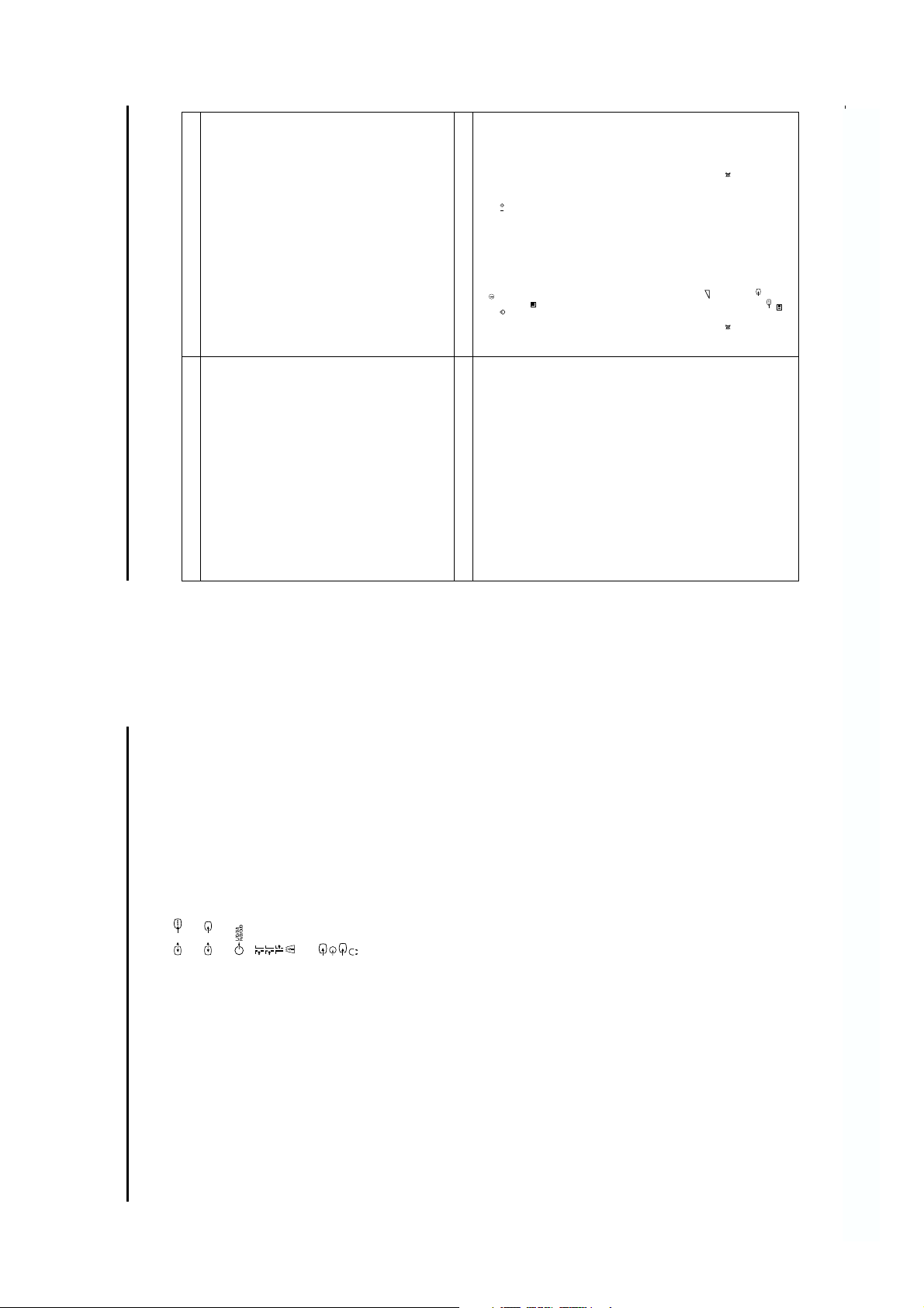
Additional Information
21-pin Euro connector (CENELEC standard)
21-pin Euro connector (CENELEC standard)
Audio outputs - phono jacks
TV audio/video output.
including audio/video input, S-video input,
selectable audio/video output.
s
2/
RF Out
Conditional Access Module (CAM) socket
Video input - phono jack
Audio inputs - phono jacks
S video input - 4 pin DIN
Headphones jack - minijack stereo
1 RF In (Digital)
2 RF In (Analogue)
MODEM Modem connection
3
s
3
Concealed Side Terminals
Accessories Supplied
RM-933 remote control (1)
RF Loopthrough Cable (1)
IEC designated size AA battery (2)
SCART Adaptor (1)
SCART Lead (1)
1/
Rear Terminals
including audio/video input, YUV input,
Design and specifications are subject to change without notice.
2x7W (RMS)
Specifications
TV System
B/G, DVB-T
Colour System
PAL
NTSC 3.58, 4.43 (only Video In)
Channel Coverage
VHF:0-12, 5A, 9A
UHF : 28 to 69
CATV : S01 to S03, S1 to S41
Picture Tube
FD Trinitron WIDE Approx. 82cm (32 inches)
Sound Output
Left/Right: 2x14W (music power)
Power Consumption
111W
Dimensions (w x h x d)
Approx. 883 x 567 x 562mm
Weight
Approx. 65kg
- 12 -
SECTION 2 DISASSEMBLY
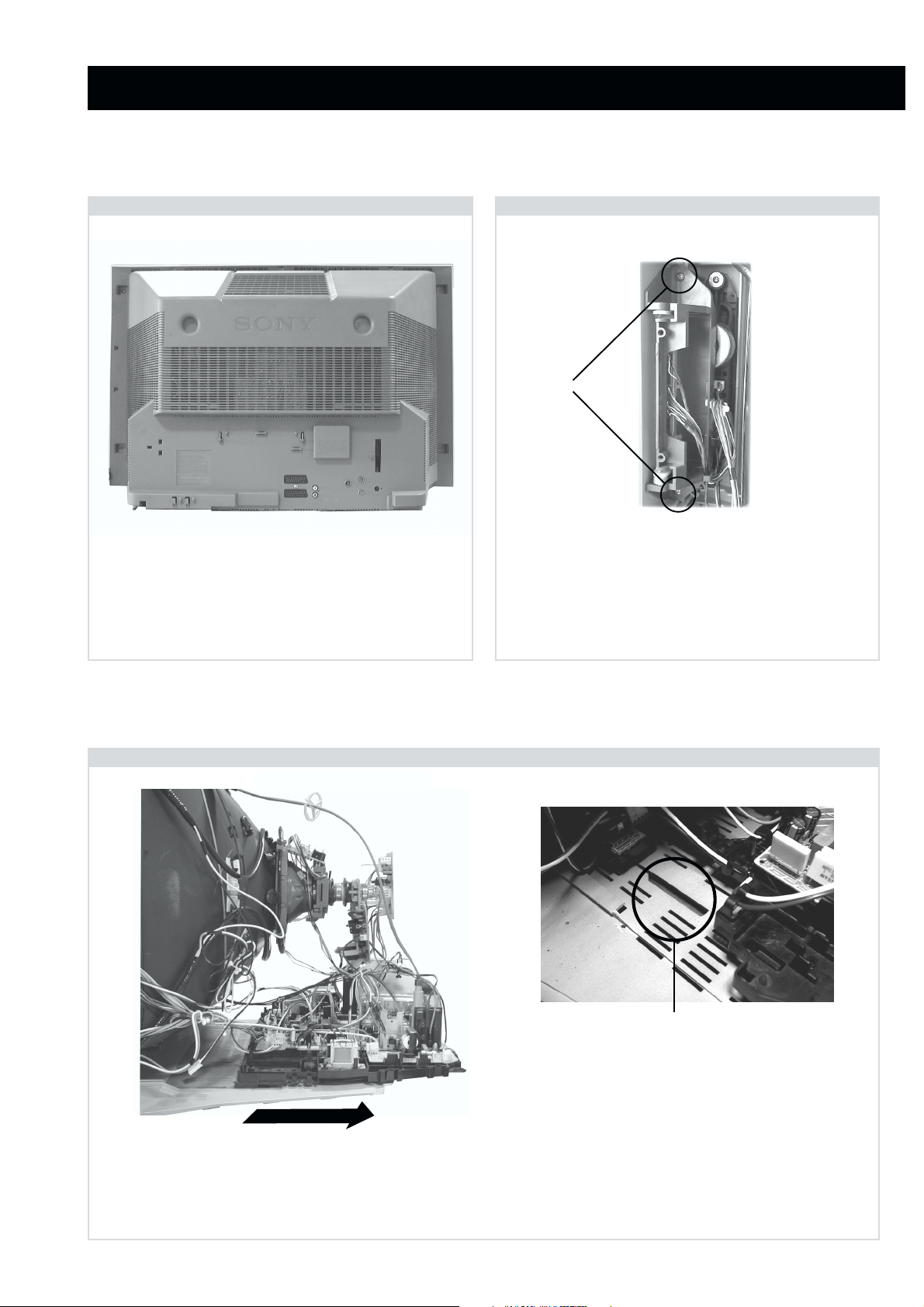
2-1. Rear Cover Removal
<=
<=
=>
=>
=>
Remove the rear cover fixing screws indicated and withdraw
the rear cover from the beznet.
<=
<=
2-2. Side Control Module Removal
<=
<=
Screws
<=
Remove the two screws fixing the user control module to the
side of the set. The control module can then be removed by
sliding it towards the rear of the set allowing access to the H2
Board.
2-3. Chassis Removal and Refitting
To remove lift the main bracket rear slightly and slide the
chassis away from the beznet. Ensure that the interconnecting
leads are released from their purse locks to prevent damage
being caused.
When refitting the chassis ensure that the main
bracket is located in the beznet guide slots before
sliding the chassis forwards. Refit the
interconnecting leads in their respective purse locks.
- 13 -
2-4. Service Position
2-5. F6 and H8 Board Removal
Position the chassis as indicated to access the solder side
of the PWB’s. To gain access to the A Board follow the
instructions on page 16. [Removal and Replacement of the
main bracket bottom plates ].
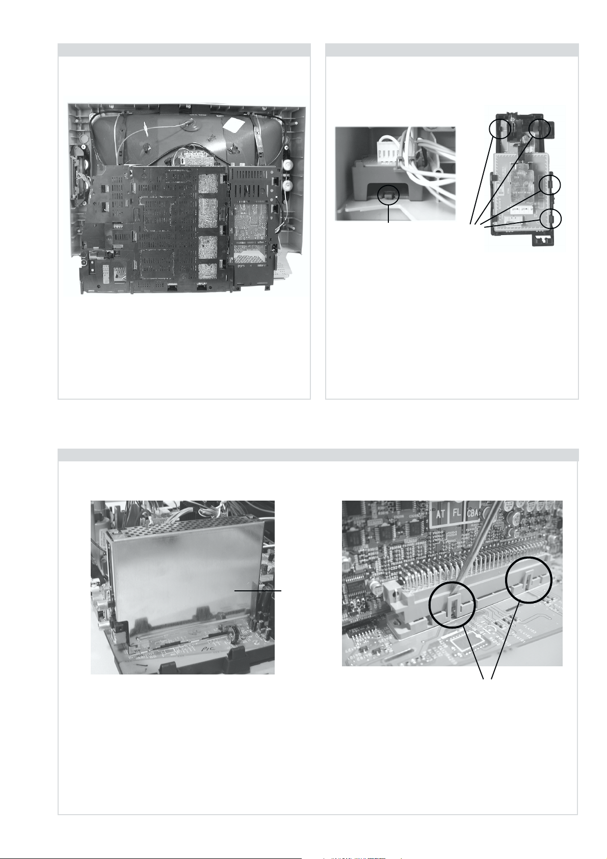
2-6. N Board Removal
Clip
Clips
Release the clip circled and pull the F6 bracket towards the
rear of the set. The bracket can then be removed to allow
access to the boards.
To remove the F6 and H8 Boards release the clips circled and
ease the boards gently away from the support bracket.
Shield
case
Clips
Remove the shield case by pulling vertically until it is clear of the N Board. Release the N board socket retaining clips, circled, by
gently prising them with a screwdriver and carefully lift the N Board vertically.
- 14 -
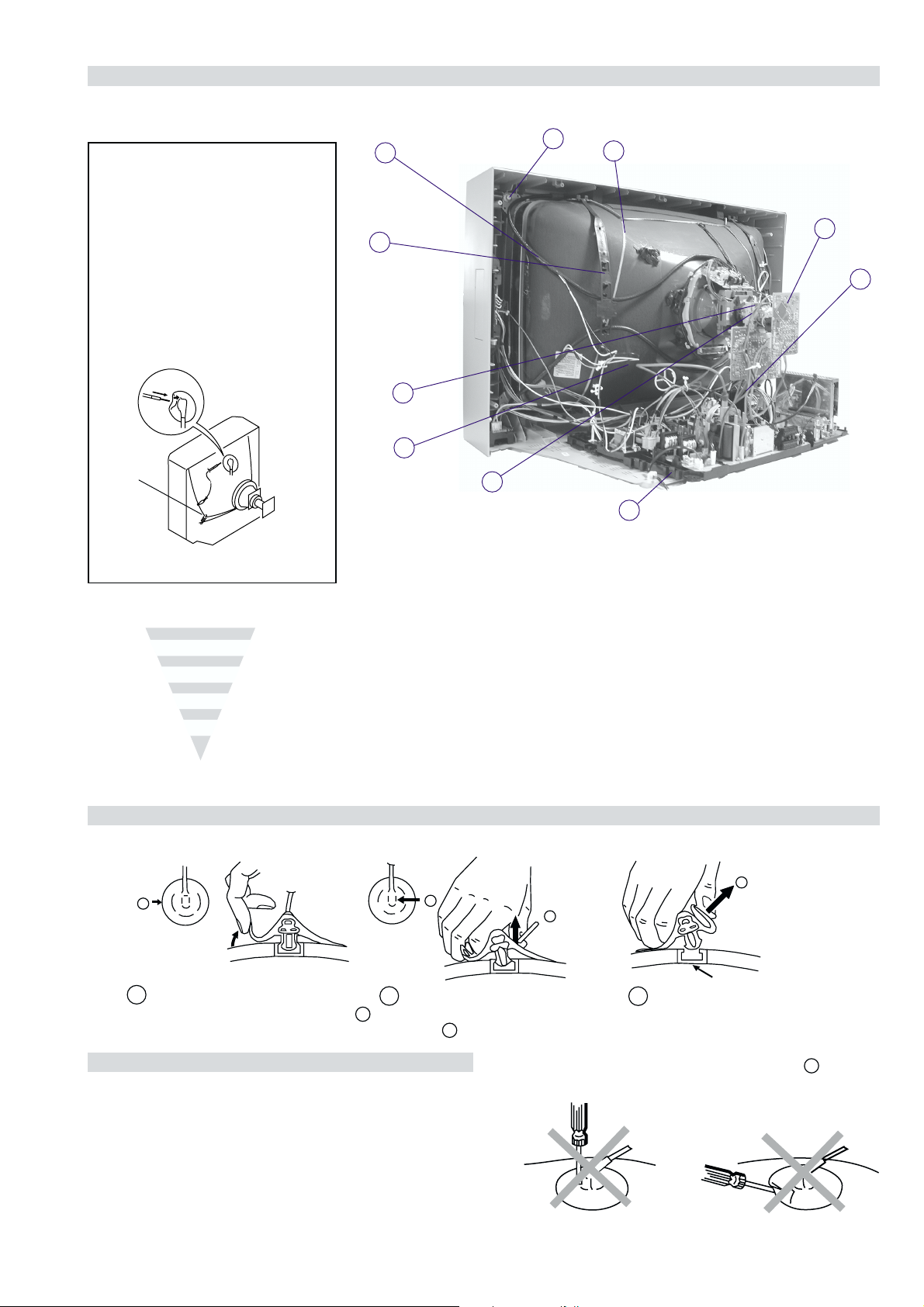
2-7. Picture Tube Removal
WARNING:
BEFORE REMOVING
THE ANODE CAP
High voltage remains in the CRT even
after the power is disconnected. To
avoid electric shock, discharge CRT
before attempting to remove the anode
cap. Short between anode and CRT
coated earth ground strap.
Coated Earth
Ground Strap
8
10
9
3
7
2
6
1
5
4
1. Discharge the anode of the CRT and remove the anode cap.
2. Unplug all interconnecting leads from the Deflection yoke, neck
assy, degaussing coils and CRT grounding strap.
3. Remove the C Board from the CRT.
4. Remove the chassis assembly.
5. Loosen the Neck assembly fixing screw and remove.
6. Loosen the Deflection yoke fixing screw and remove.
7. Place the set with the CRT face down on a cushion and remove
the Degaussing Coil holders.
8. Remove the Degaussing Coils.
9. Remove the CRT grounding strap and spring tentioners.
10. Unscrew the four CRT fixing screws [ located on each CRT
corner ] and remove the CRT.
[Take care not to handle the CRT by the neck.]
Removal of the Anode-Cap
* REMOVING PROCEDURES.
a
1
Turn up one side of the rubber cap in
the direction indicated by the arrow a
b
2 Using a thumb pull up the rubber cap
firmly in the direction indicated by the
arrow b
How to handle the Anode-Cap
1. To prevent damaging the surface of the anode-cap do not use
sharp materials.
2. Do not apply too great a pressure on the rubber, as this may cause
damage to the anode connector.
3. A metal fitting called a shatter hook terminal is fitted inside the
rubber cap.
4. Do not turn the rubber foot over excessively, this may cause
damage if the shatter hook sticks out.
c
b
Anode button
3 When one side of the rubber cap is
separated from the anode button, the
anode-cap can be removed by turning
up the rubber cap and pulling it up in
the direction of the arrow c
- 15 -
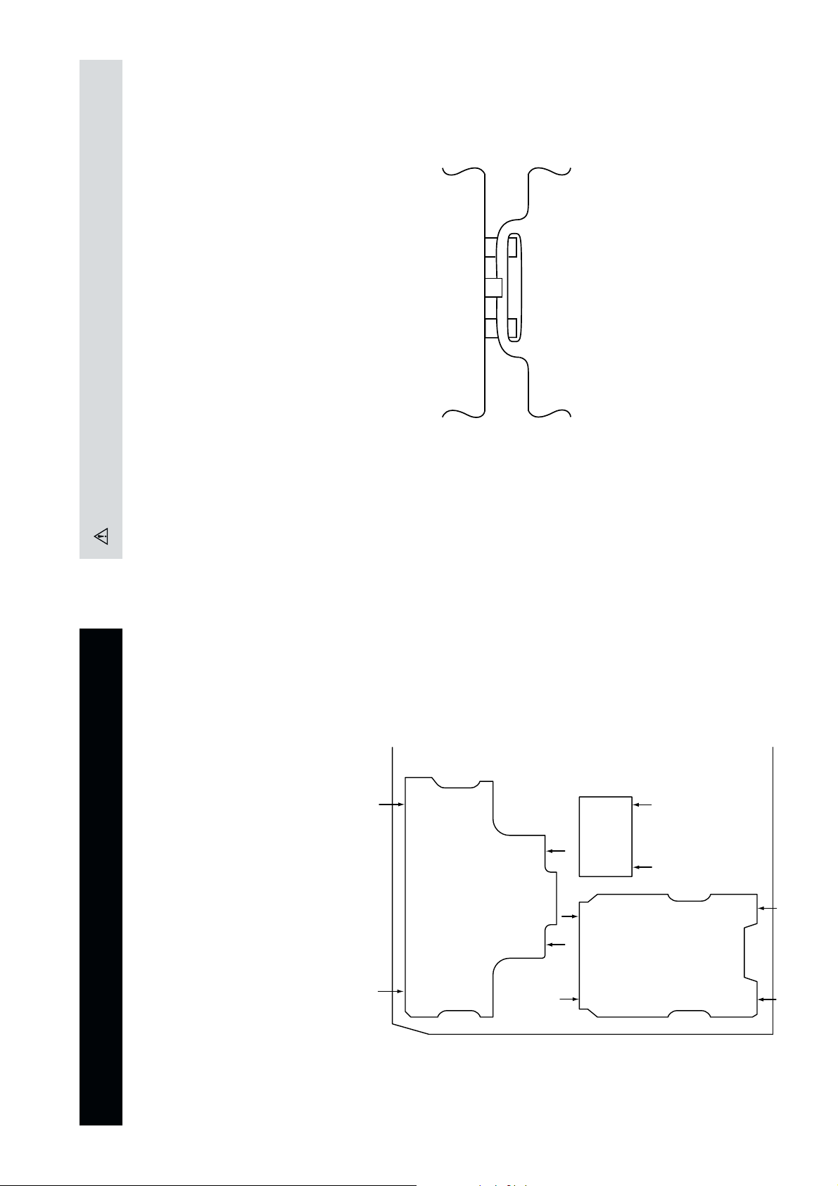
For safety reasons, on no account should the plates be re-
moved and not refitted after servicing.
(2) REFITTING THE PLATES
Because the plates differ in size it is important that the correct plates are refitted in their original
location.
Please note that the plates need to be rotated 180 degrees from their cut position to allow the tabs to
be fitted into their catch positions.
Catch
Ta b
REMOVAL AND REPLACEMENT OF THE MAIN-BRACKET
BOTTOM PLATES.
Only remove the necessary plate to gain access to the printed wiring board.
In the event of servicing being required to the solder side of the A Board printed wiring board, the
bottom plates fitted to the main chassis bracket require to be removed.
This is performed by cutting the gates with a sharp wire cutter at the locations indicated by the
arrows.
(1) REMOVING THE PLATES
Note : There are 3 plates fitted to the main bracket and secured by 3 gates.
- 16 -
SECTION 3 SET-UP ADJUSTMENTS
• When complete readjustment is necessary or a new picture
tube is installed, carry out the following adjustments.
• Unless there are specific instructions to the contrary, carry
out these adjustments with the rated power supply.
• Unless there are specific instructions to the contrary, set the
controls and switches to the following settings :
Contrast .................... 80% [or remote control normal]
Brightness ................... 50%
Preparation:
1. In order to reduce the influence of geomagnetism on the
set’s picture tube, face it in an easterly or westerly direction.
2. Switch on the set’s power and degauss with the degausser.
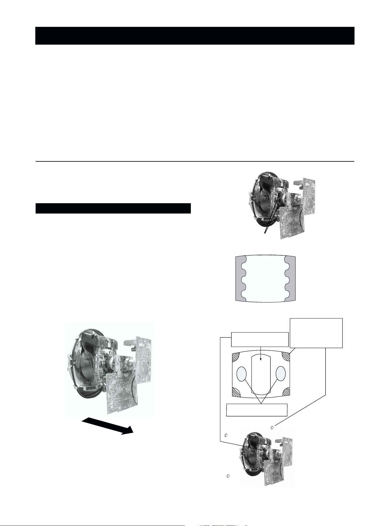
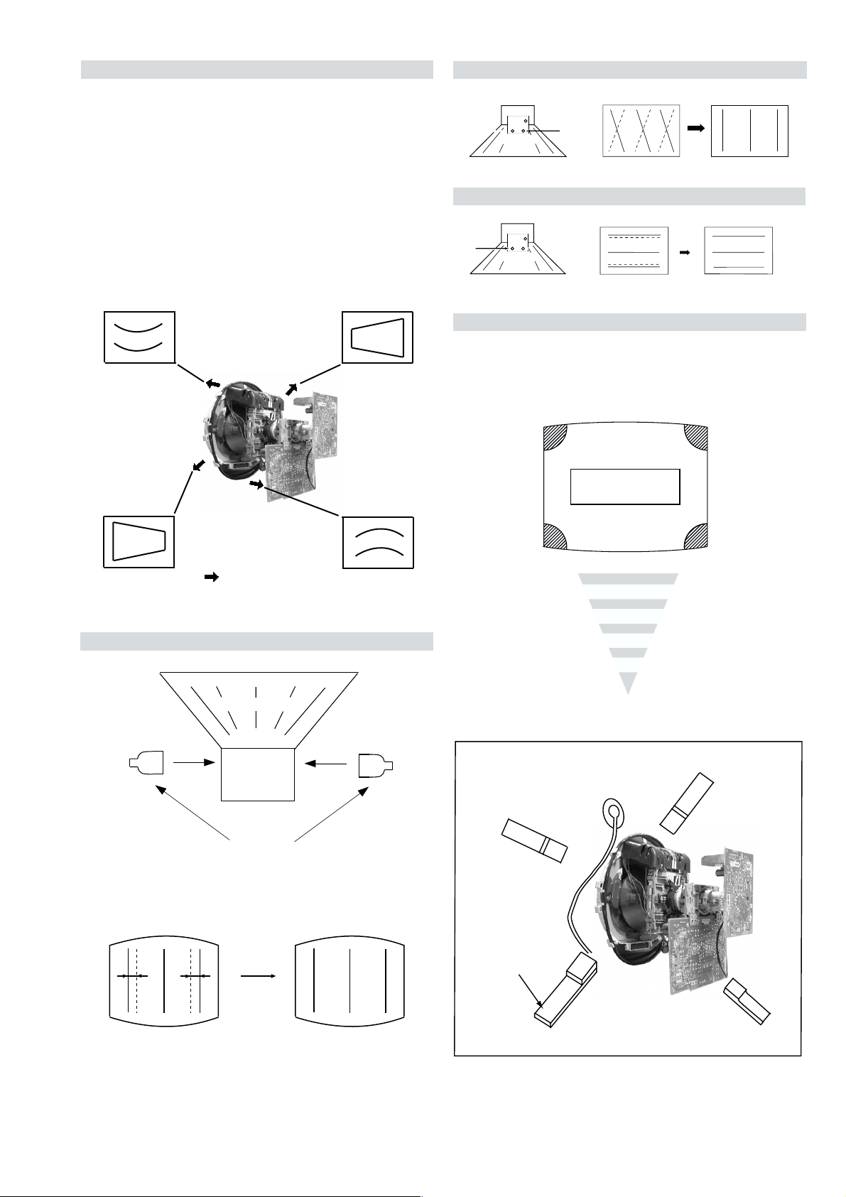
3-1. Beam Landing
1. Input an all white signal from the pattern generator. Set the
Contrast and Brightness to normal.
2. Set the pattern generator raster signal to Red.
3. Move the deflection yoke forward and adjust with the
purity control so that the Red is at the centre and the Blue
and Green take up equally sized areas on each side of the
screen. [See Fig.3-1 - 3-3].
4. Move the deflection yoke backwards and adjust so that the
entire screen becomes Red. [See Fig.3-1]
5. Switch the raster signal to Blue, then to Green and verify
the condition.
6. When the position of the deflection yoke has been
determined, fasten the deflection yoke with the screws.
7. If the beam does not land correctly in all the corners, use a
magnet to correct it. [See Fig.3-4]
Carry out the adjustments in the following order :
3-1. Beam Landing.
3-2. Convergence.
3-3. Focus.
3-4. White Balance.
Note : Test equipment required.
1. Color bar/pattern generator.
2. Degausser.
3. Oscilloscope.
4. Digital multimeter.
Fig. 3-2.
Purity
Fig. 3-3.
GREEN
RED
BLUE
Disk magnets or
rotatable disk
Purity control corrects
this area
magnets correct
these areas (a-d)
Fig. 3-1.
Caution :
High voltages are present on the Deflection yoke terminals
- take care when handling the Deflection yoke whilst carrying
out adjustments.
- 17 -
Disk Magnets
Fig.3-4
a
cd
Deflection yoke positioning
corrects these areas
b

GBR
GBR
GBR
G
B
R
GBR
G
B
R
3-2. Convergence
B
G
R
a
b
R
G
B
b
a
Preparation:
4. If the V.STAT magnet is moved in the direction of the (a)
and (b) arrows, the Red, Green and Blue points move as
indicated below.
• Before starting this adjustment, adjust the focus, horizontal
size and vertical size.
• Minimize the Brightness setting.
• Input a dot pattern from the pattern generator.
Horizontal and Vertical Static Convergence
Center dot
R
G
B
H STAT
convergence
control
R
G
B
V.STAT Vertical Static Magnet
C Board
RV702 (H STAT)
H STAT Convergence
(on mount side)
a
b
a
a
b
a
b
B
G
R
R
R
b
B
G
R
a
B
G
b
B
G
Fig.3-5
1. [Moving horizontally], adjust the H.STAT control so that
the Red, Green and Blue points are on top of each other at
the centre of the screen.
Operation of the BMC (Hexapole) magnet.
2. [Moving vertically], adjust the V.STAT magnet so that the
Red, Green and Blue points are on top of each other at the
centre of the screen.
3. If the H.STAT variable resistor is unable to bring the Red,
Green and Blue points together at the centre of the screen,
adjust the horizontal convergence with the H.STAT variable
resistor and the V.STAT magnet in the manner indicated
below.
[In this case, the H.STAT variable resistor and the V.STAT
magnet influence each other].
• Tilt the V.STAT magnet and adjust the static convergence by
opening or closing the V.STAT magnet.
The movement of the magnets interact with each other and so
the respective dot position should be monitored while carrying
out this adjustment.
Use the H.STAT VR to adjust the Red, Green and Blue dots so
that they coincide at the centre of the screen
(by moving the dots in the horizontal direction).
- 18 -
+
YCH VR
Deflection Yoke
+
+
Geometry Adjustment.
Preparation:
Before starting this adjustment, adjust the horizontal and
vertical static convergence.
1. Remove the deflection yoke spacer.
2. Tilt the deflection yoke as indicated in the figure below and
optimise the geometry.
Tilting the DY Up and Down will balance the upper and
lower pin adjustment.
Tilting the DY Left and Right will balance the H-Trap
adjustment.
3. Re-install the deflection yoke spacer.
YCH Adjustment
TLV Adjustment
+
+
TLV VR
+
Deflection Yoke
Screen Corner Convergence
If you are unable to adjust the corner convergence properly,
this can be corrected with the use of permalloy magnets.
HTIL Adjustment
Tilt Direction
Deflection Yoke
TLH pieces
a
a-d: screen-corner
convergence defect
c
Install the permalloy assembly
for the area that needs correcting.
b
b
d
a
HTIL correction can be performed by adding a TLH correction
assembly to the Deflection yoke.
Permalloy Assy
X-4387-214-1
- 19 -
d
Convergence adjustment with permalloy
c
 Loading...