

SONY KD-32DX400 Service Manual

SERVICE MANUAL
FE-2
CHASSIS
MODEL COMMANDER DEST CHASSIS NO.
KD-28DX40U RM-933 UK SCC-Q52K-A
MODEL COMMANDER DEST CHASSIS NO.
KD-32DX40U RM-933 UK SCC-Q52L-A
KD-28/32DX40
- 1 -
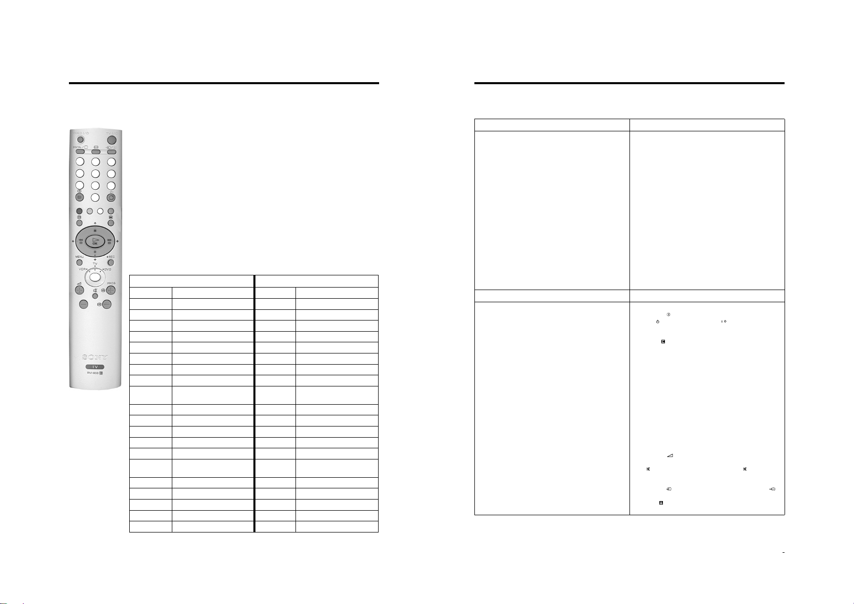
RM-933

TABLE OF CONTENTS
Section Title Pag e Section Title Pag e
Specifications .................... 3
Connectors .................... 4
Self Diagnostic Software .................... 5
1. GENERAL
Automatically Tuning the TV .................... 6
Finding the V ideo Channel .................... 6
Selecting Digital or Analogue
Mode .................... 6
The Programme Index T able .................... 6
The Channel Index Menu .................... 6
Vi ewing Digital T elete xt .................... 7
T eletext(Analogue) .................... 8
The Digital EPG Menu .................... 8
The Digital INFO Display .................... 9
The TV Menu System .................... 10
The Set Up Menu .................... 11
Remote Control of Equipment .................... 12
Troubleshooting .................... 12
2. DISASSEMBLY
2-1. Rear Cover Removal .................... 13
2-2. Side Control Module Removal .................... 13
2-3. Chassis Removal .................... 13
2-4. Service Position .................... 14
2-5. F6 and H8 Board Removal .................... 14
2-6. N Board Removal .................... 14
2-7. Picture Tube Remov al .................... 15
Bottom Plates .................... 16
3. SET-UP ADJUSTMENTS
4. CIRCUIT ADJUSTMENTS
4-1. Electrical Adjustments .................... 21
4-2. T est Mode 1 .................... 23
4-3. T est Mode 2 .................... 23
5. DIAGRAMS
5-1. Block Diagrams (1) .................... 24
Block Diagrams (2) .................... 25
Block Diagrams (3) .................... 26
5-2. Circuit Board Location .................... 27
5-3. Schematic Diagrams and
Printed Wiring Boards .................... 27
* A Board .................... 29
* C Board .................... 32
* VM Board .................... 33
* A1 Board .................... 34
* B Board .................... 36
* H2 Board .................... 36
* D3 Board .................... 37
* H8 Board .................... 37
* F3 Board .................... 37
* D2 Board .................... 37
* F6 Board .................... 37
5-4. Semiconductors .................... 38
5-5. IC Blocks .................... 40
6. EXPLODED VIEWS
6-1. Chassis .................... 41
6-2. Picture Tube .................... 42
3-1. Beam Landing .................... 17
3-2. Convergence .................... 18
3-3. Focus Adjustment .................... 20
3-4. Screen (G2), White Balance .................... 20
CAUTION
SHORT CIRCUIT THE ANODE OF THE PICTURE TUBE AND THE
ANODE CAP TO THE METAL CHASSIS, CRT SHIELD, OR THE
CARBON PAINTED ON THE CRT, AFTER REMOVAL OF THE
ANODE CAP.
WARNING !!
AN ISOLATION TRANSFORMER SHOULD BE USED DURING
ANY SERVICE WORK TO AVOID POSSIBLE SHOCK HAZARD
DUE TO LIVE CHASSIS, THE CHASSIS OF THIS RECEIVER IS
DIRECTLY CONNECTED TO THE POWER LINE.
SAFETY-RELATED COMPONENT WARNING !!
COMPONENTS IDENTIFIED BY SHADING AND MARKED ON
THE SCHEMATIC DIAGRAMS, EXPLODED VIEWS AND IN THE
PARTS LIST ARE CRITICAL FOR SAFE OPERATION. REPLACE
THESE COMPONENTS WITH SONY PARTS WHOSE PART
NUMBERS APPEAR AS SHOWN IN THIS MANUAL OR IN
SUPPLEMENTS PUBLISHED BY SONY.
7. ELECTRICAL PARTS LIST .................... 43
ATTENTION
APRES AVOIR DECONNECTE LE CAP DE’LANODE,
COURT-CIRCUITER L’ANODE DU TUBE CATHODIQUE ET
CELUI DE L’ANODE DU CAP AU CHASSIS METALLIQUE DE
L’APPAREIL, OU AU COUCHE DE CARBONE PEINTE SUR LE
TUBE CATHODIQUE OU AU BLINDAGE DU TUBE
CATHODIQUE.
ATTENTION !!
AFIN D’EVITER TOUT RISQUE D’ELECTROCUTION
PROVENANT D’UN CHÁSSIS SOUS TENTION, UN
TRANSFORMATEUR D’ISOLEMENT DOIT ETRE UTILISÈ LORS
DE TOUT DÈPANNAGE LE CHÁSSIS DE CE RÈCEPTEUR EST
DIRECTMENT RACCORDÈ Á L’ALIMENTATION SECTEUR.
ATTENTION AUX COMPOSANTS RELATIFS Á
LA SECURITÈ!!
LES COMPOSANTS IDENTIFIÈS PAR UNE TRAME ET PAR UNE
MARQUE SUR LES SCHÈMAS DE PRINCIPE, LES VUES
EXPLOSÈES ET LES LISTES DE PIECES SONT D’UNE IMPOR-
TANCE CRITIQUE POUR LA SÈCURITÈ DU FONCTIONNEMENT,
NE LES REMPLACER QUE PAR DES COMPSANTS SONY DONT
LE NUMÈRO DE PIÈCE EST INDIQUÈ DANS LE PRÈSENT
MANUEL OU DANS DES SUPPLÈMENTS PUBLIÈS PAR SONY.
- 2 -
LEDOMMETI metsySnoisiveleT metsySoeretS egarevoClennahC metsySroloC
UI oeretSMACIN96E-12E:FHUI
MACES,LAP
85.3CSTN,34.4CSTN
)NIOEDIV(
ebuTerutciP
skcaJonohPoiduArofelbairavsrotcennoCtuptuO
latigiD
kcajenohpdaeHkcajinimoerets
stupnioiduAskcajonohp
stupnioediVskcajonohp
tupnioediVSNIDnip4
nortinirTDFyalpsiDtalF
)sehcni82(mc17xorppA
derusaemerutcipmc66xorppA(
U04XD82-DK)yllanogaid
)sehcni23(mc28xorppA
derusaemerutcipmc67xorppA(
U04XD23-DK)yllanogaid
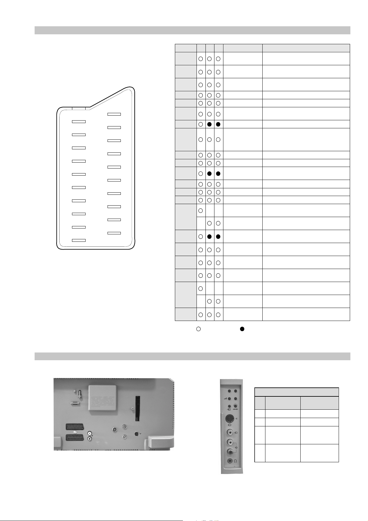
]RAER[slanimreTtuptuO/tupnI
rotcennocoruEnip-12:1
)dradnatsCELENEC(
rotcennocoruEnip-12:2
slangiS
]EDIS[slanimreTtuptuO/tupnI
.BGRrofstupnI
.slangis
.oediVSrofstupnI
)elbatceles(
kcaJmedoM
AICMCP
.slangisoediVdnaoiduArofstupnI
oiduAdnaoediVVTfostuptuO
.slangisoediVdnaoiduArofstupnI
.slangisoiduAdnaoediVVTfostuptuO
tuptuodnuoS
rekaepstfeLdnathgiR)SMR(W7x2)rewoPcisuM(W41x2
snoitacificepSlareneG
stnemeriuqeRrewoPV042-022
noitpmusnoCrewoP
snoisnemiD
thgieW
seirosseccAdeilppuS
serutaeFrehtO
cdV3
stnemeriuqerrewoP
.ecitontuohtiwegnahcottcejbuserasnoitacificepsdnangiseD
)04XD82-DK(W09
)04XD23-DK(W88
)04XD82-DK(mm045x794x608xorppA
)04XD23-DK(mm485x465x198xorppA
)04XD82-DK(gk34xorppA
)04XD23-DK(gk5.06xorppA
)1(rednammoCetomeR339-MR
)2(yrettab6RdetangisedCEI
txeteleT,noitcetedotuAmetsysVT
ybloDlautriV
lortnoCderarfnI:metsySlortnoCetomeR
noitangisedCEIseirettab2
)AAezis(6R
metI
emaNledoM
bmoClaPFFOFFO
PIPFFOFFO
ytiroirPBGRNONO
xoBrefooWFFOFFO
1tracSNONO
2tracSNONO
)3(nitnorFNONO
4tracSFFOFFO
rotcejorPFFOFFO
G/BmroNFFOFFO
ImroNNONO
K/DmroNFFOFFO
SUAmroNFFOFFO
LmroNFFOFFO
TASmroNFFOFFO
MmroNFFOFFO
txeteleTNONO
oeretSmaciNNONO
U04XD82-DK U04XD23-DK
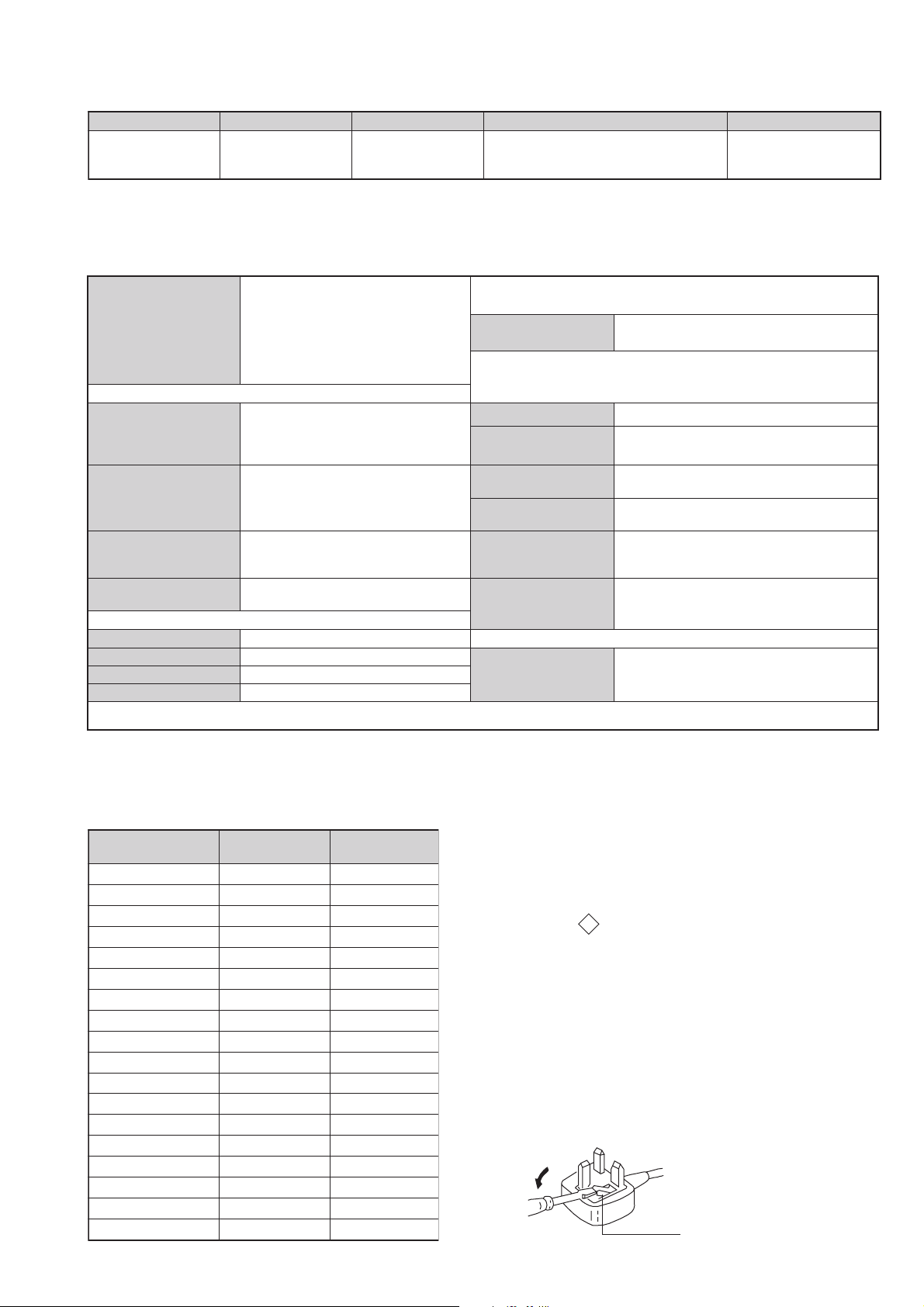
WARNING (UK Models only)
The flexible mains lead is supplied connected to a B.S. 1363 fused
plug having a fuse of 5 AMP rating. Should the fuse need to be
replaced, use a 5 AMP FUSE approved by ASTA to BS 1362, ie one
that carries the
IF THE PLUG SUPPLIED WITH THIS APPLIANCE IS NOT SUITABLE FOR THE OUTLET SOCKETS IN YOUR HOME, IT SHOULD
BE CUT OFF AND AN APPROPRIATE PLUG FITTED. THE PLUG
SEVERED FROM THE MAINS LEAD MUST BE DESTROYED AS A
PLUG WITH BARED WIRES IS DANGEROUS IF ENGAGED IN A
LIVE SOCKET.
When an alternative type of plug is used, it should be fitted with a
5 AMP FUSE, otherwise the circuit should be protected by a 5 AMP
FUSE at the distribution board.
- 3 -
ASA
T
mark.
How to replace the fuse.
Open the fuse compartment with
a screwdriver blade and replace
the fuse.
FUSE
21 pin connector
21
19
17
15
13
11
9
7
5
3
1
20
18
16
14
12
10
8
6
4
2
Pin No 1 2 4 Signal Signal level
1 Audio output B
2
3
4 Ground (audio)
5 Ground (blue)
6 Audio input A
7 Blue input 0.7 +/- 3dB, 75 ohms positive
8 Function select
9 Ground (green)
10 Open
11 Green Green signal : 0.7 +/- 3dB, 75 ohms,
12 Open
13 Ground (red)
14 Ground (blanking)
15
_ (S signal Chroma
16 Blanking input
17 Ground (video
18 Ground (video
19 Video output 1V +/- 3dB, 75ohms, positive sync 0.3V
20
_ Video input
21 Common ground
(right)
Audio output B
(right)
Audio output A
(left)
(left)
(AV control)
_ _ Red input 0.7 +/- 3dB, 75 ohms, positive
input)
(Ys signal)
output)
input)
_ _ Video input 1V +/- 3dB, 75ohms, positive sync 0.3V
Y (S signal)
(plug, shield)
Standard level : 0.5V rms
Output impedence : Less than 1kohm*
Standard level : 0.5V rms
Output impedence : More than 10kohm*
Standard level : 0.5V rms
Output impedence : Less than 1kohm*
Standard level : 0.5V rms
Output impedence : More than 10kohm*
High state (9.5-12V) : Part mode
Low state (0-2V) : TV mode
Input impedence : More than 10K ohms
Input capacitance : Less than 2nF
positive
0.3 +/- 3dB, 75 ohms, positive
High state (1-3V) Low state (0-0.4V)
Input impedence : 75 ohms
(-3+10dB)
(-3+10dB)
1V +/- 3dB, 75ohms, positive sync 0.3V
(-3+10dB)
Connected Not Connected (open) * at 20Hz - 20kHz
Rear Connection Panel Front Connection Panel
p
- +
niP
oN
S-Video
socket
s
4
4
MONO
L/G/S/I
4
R/D/D/D
1dnuorG2dnuorG3tupni)langisS(Y,mho57Bd3-/+V1
4tupni)langisS(CBd3-/+V3.0
langiS leveLlangiS
noitarugifnocniptekcosoediVS
V3.0.cnySevitisop
Bd01+3-
evitisop,mho57
.cnyS
- 4 -
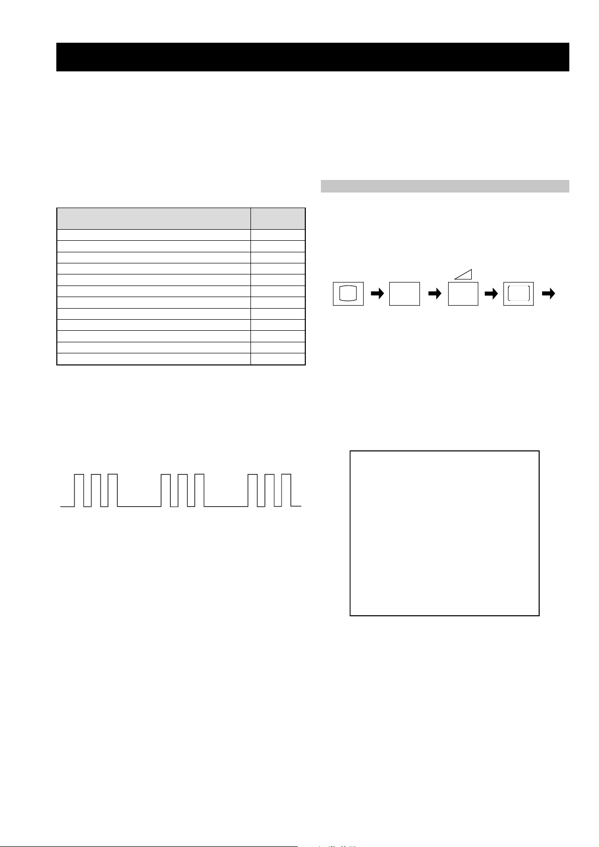
FE-2 SELF DIAGNOSTIC SOFTWARE
The identification of errors within the FE-2 chassis is triggered in one of two ways :- 1: Busy or 2: Device failure to respond to IIC. In the event
of one of these situations arising the software will first try to release the bus if busy (Failure to do so will report with a continuous flashing
LED) and then communicate with each device in turn to establish if a device is faulty. If a device is found to be faulty the rele vant device number
will be displayed through the LED (Series of flashes which must be counted) See table 1., non fatal errors are reported using this method.
Each time the software detects an error it is stored within the NVM. See T able 2.
Table 1
egasseMrorrE
rorreoN00
devreseR10
)noitcetorPtnerruCrevO(PCO20
desUtoN30
cnySlacitreVoN40
norewoptarorrERKI50
norewoptawolsenilatadro/dnakcolcsubCII60
norewoptaegdelwonkcasubCIIonMVN70
desUtoN80
norewoptaegdelwonkcaonrenuT90
rorrErossecorPdnuoS01
rorrestlov8rellortnocelgnuJ11
Flash Timing Example : e.g. error number 3
StBy LED
ON
ON ON
How to enter into T able 2
DEL
edoC
1. Turn on the main power switch of the TV set and enter into
the ‘Stanby Mode’.
2. Press the following sequence of buttons on the Remote
Commander.
i+
(ON SCREEN (DIGIT 5) (VOLUME -) (TV)
DISPLAY)
5
-
3. The following table will be displayed indicating the error
count.
Table 2
UNEMRORRE
OFF
OFF
20E
30E
40E
50E
60E
70E
80E
90E
01E
11E
SRUOH
SETUNIM
PCO
A/NPVO
CNYSV
RKI
CII
MVN
ELGNUJ
RENUT
PDNUOS
V8
EMITGNIKROW
)552,0(
0
)552,0(
0
)552,0(
0
)552,0(
0
)552,0(
0
)552,0(
0
)552,0(
0
)552,0(
0
)552,0(
0
)552,0(
0
2
11
Note: T o clear the error count data press ‘80’ on the Remote
commander.
- 5 -
- 6 -
OK
O
K
O
K
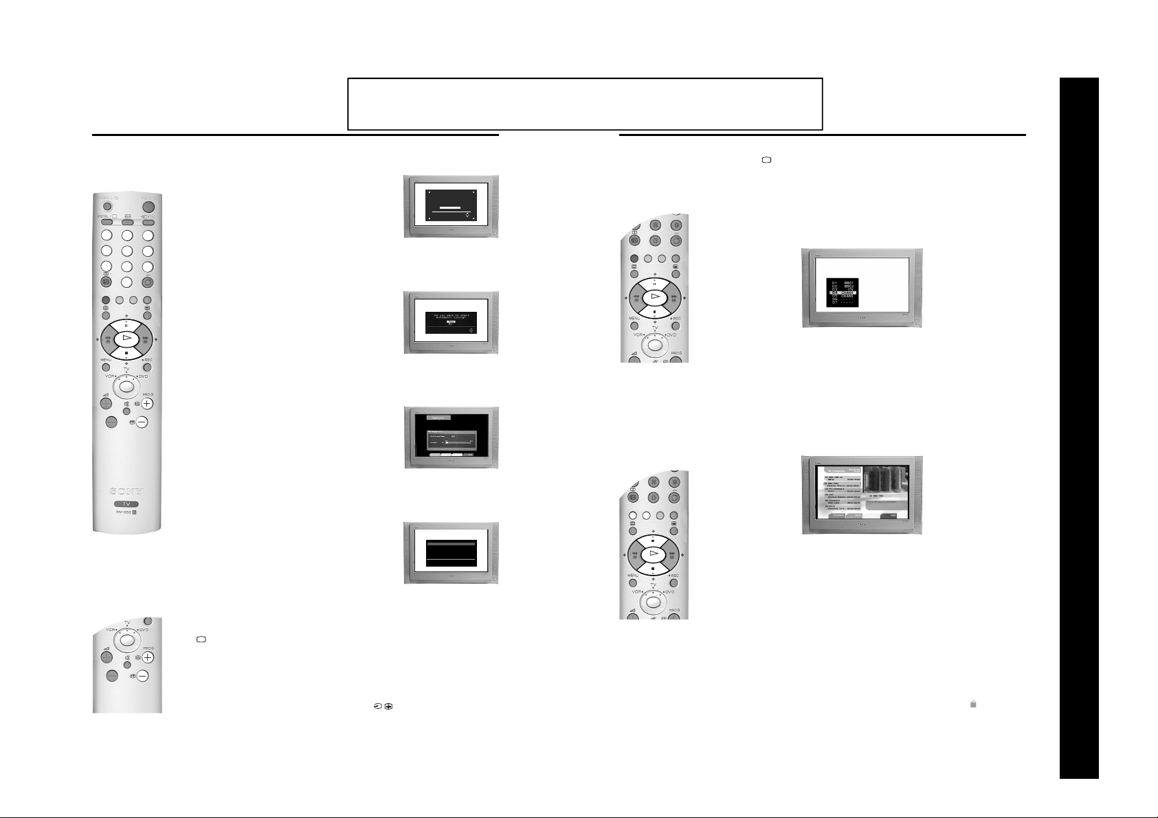
Getting Started
5. Automatically tuning the TV
1. When you switch on the TV for the first time a menu appears on the
screen asking you to check if the picture is slanted. (Sometimes the
Earth’s natural magnetism can cause the screen to look tilted.)
VIDEO
DIGITAL
TV
/
/
a) If no correction is required, press the V or v buttons on the
remote control to highlight ‘Not necessary’ and press the OK
button.
1
2
3
b) If some correction is required, press the V or v buttons on the
4
5
6
7
8
9
0
O
K
remote control to highlight ‘Adjust now’, then press the OK
button. Correct the slant by pressing the V or v buttons then
press the OK button to store.
2. The autotune prompt screen appears. Press the OK button to select
‘Yes’. The autotune procedure begins.
The Digital autotune display appears on screen and the search and
store procedure begins. All the a v ai lab le Digital chann els wil l no w be
captured and stored. As this may take some time, a message is
included in the display to inform you of the tuning progress.
When Digital tuning is complete, the analogue display appears
automatically and the search and store procedure for the analogue
channels begins.
If no Digital and no analogue channels are found, a menu appears
asking you to confirm your aerial is connected. After checking the
aerial has been connected press OK to begin the autotune
procedure again.
Once all Digital and analogue channels have been captured and
stored, the TV returns to normal operation and displays the Digital
channel captured on channel number 1.
The operating instructions mentioned here are partial abstracts from the ‘Operating
Instruction Manual’. The page numbers of the ‘Operating Instruction Manual’ remain
as in the manual.
Selecting Digital or analogue mode
Press the DIGITAL/ button on the remote control to switch between Digital and analogue mode. To
Checking the picture tilt.
If picture slants, please
adjust picture rotation.
Not necessary
Adjust now
The Programme Index table
OK
check if you are watching a Digital or analogue mode press the PROG +/- button. If you are watching a
digital programme a banner will appear momentarily at the top of the screen.
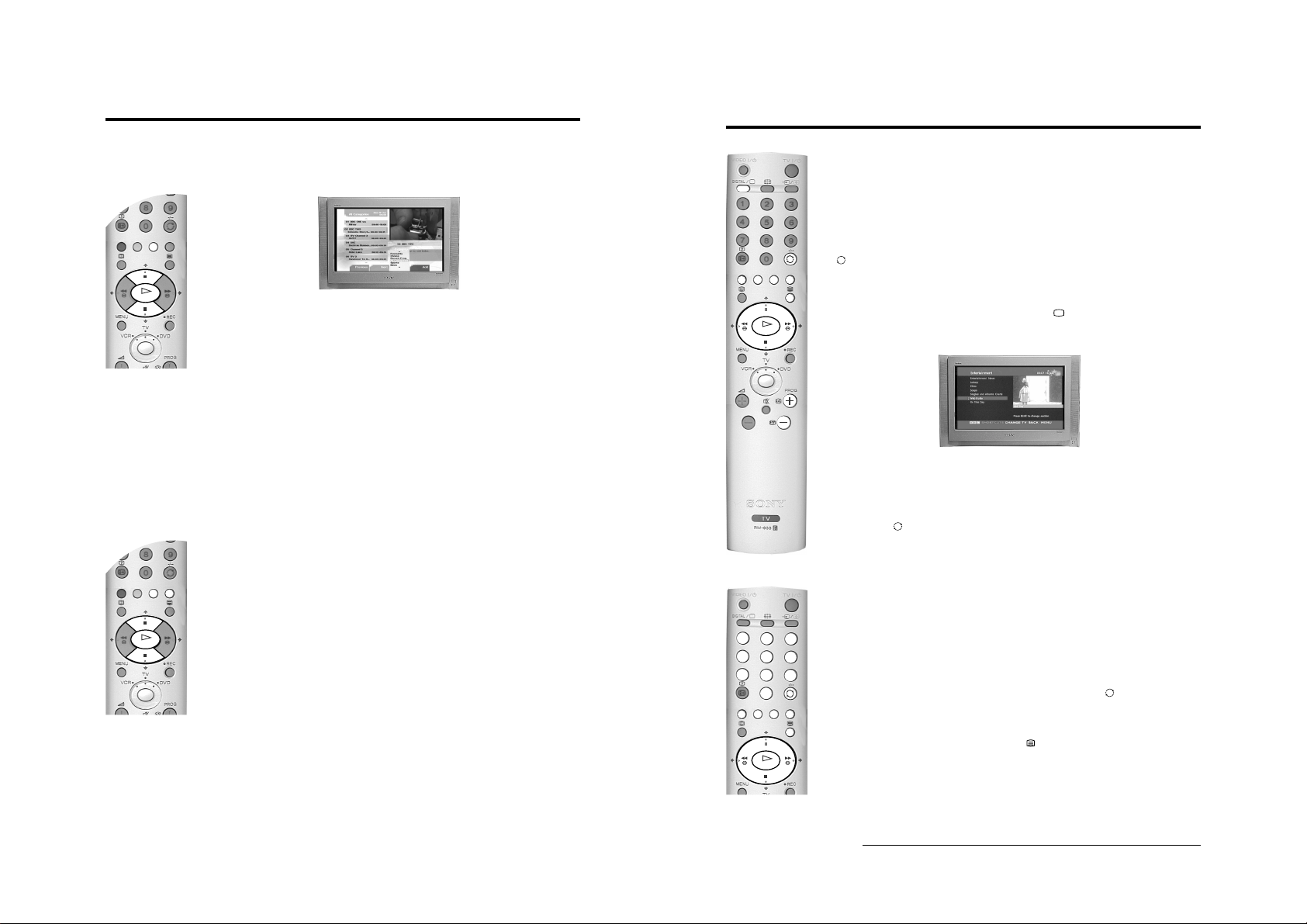
The ‘Program me Index t able’ is a quick and easy way to search for a channel you wish to view. The
‘Programme Index table’ is only available in analogue mode.
1. Press the OK button to display the ‘Programme Index table’ on screen.
The autotune prompt screen.
2. Press the v or V button to scroll through the list until the channel you wish to view is highlighted.
3. Press the OK button to display your chosen channel on the TV screen.
The Channel Index menu
Tuning the Digital channels.
The ‘Channel Index menu’ provides you with a quick and easy way to:-
a) View a complete list of the programmes available for selection,
b) Obtain a preview of the programmes contained in the list,
c) Search for a programme quickly by selecting from different categories of programmes,
d) Store programmes into a list of favourites.
Basic Operation
SECTION 1 GENERAL
Note: If no Digital channels are captured, the analogue channel that is stored
on channel number 1 is displayed.
3. To view programmes, press the PROG+/- buttons or the numbered
buttons.
6. Finding the video channel
If you connected a VCR to your TV when following the ‘Connecting an
aerial and a VCR’ instructions, you will now need to find your video
channel. Ensure the TV is in analogue mode. If it is not, press the
DIGITAL/ button on the remote control.
1. Press the PROG +/- buttons on the remote control until the picture
from the pre-recorded tape appears on the TV screen.
Notes: If you wish to move your video channel to a different programme number,
refer to ‘The Set Up menu’ section of this manual.
If you have connected your VCR using a scart lead, press the /
button on the remote control until the picture from the pre-recorded tape
appears on the TV screen. (Refer to ‘Connecting additional equipment’).
6
Getting Started
Tuning the analogue channels.
Auto Tuning
Programme: 02
C29
Channel :
Completed 16%
The ‘Channel Index menu’ is only available in Digital mode.
1. Press the OK button on the remote control to display the ‘Channel Index menu’ on the TV screen.
The menu contains a list of all the available channels. The name of the programme currently being
shown along with its start and finish times is shown for each of the available channels. The current
channel is previewed in the top right corner of the screen with its channel name and number
displayed below it.
2. Press the V or v buttons to move the coloured cursor up or down the list to select the desired
programme. If you do not want to select a programme from the 6 channels listed, press the GREEN
button to display the next 6 programmes or the RED button to display the preceding 6 channels.
3. Press the OK button to display the highlighted programme in the preview window*.
4. Press the OK button to exit the ‘Channel Index menu’. The programme that was being previewed will
be displayed.
*Note: If an age limit for viewing has been set and the programme selected exceeds that age limit, you will need to
enter your PIN code before the preview is displayed. Ref er to ‘Th e Mai n Men u’ for more inf ormation on the ‘PIN
Code’ feature. Programmes that exceed the age limit you have set will be identified by a symbol.
Basic Operation
9
VIDEO
/
TV
/
DIGITAL
O
K
1
2
3
6
5
4
7
8
9
0
O
K
- 7 -
Basic Operation
K
O
The Category pop-up list
The ‘Category’ pop-up list allows you to quickly search for a programme by choosing from different
categories of programmes.
1. With the ‘Channel Index menu’ on screen, press the YELLOW button to display the ‘Category’ popup list.
2. Press the V or v buttons to highlight the required category. The category you choose will be
displayed in a title bar at the top of the programme list along with the date and time.
3. Press the OK button. The ‘Channel Index menu’ will now contain o nly programmes of the type
selected.
Basic Operation
Viewing Digital Teletext
VIDEO
DIGITAL
/
K
O
Many broadcasters now provide a Digital Teletext service in the form of a dedicated Teletext channel.
TV
/
This Digital service includes high quality text and graphics along with advanced navigation options.
The appearance, content and navigation methods of all Digital Text services are decided by the
broadcaster. For example, Digital Text from the BBC may look different to Digital Text from ITV which
may use different navigation methods. Most of the Digital Text services currently available use simple
navigation method s based on the followi ng buttons:
The V, v, B and b buttons (to move around the screen),
The OK button (to select items on screen),
The button (to cancel),
The four coloured buttons (to access shortcuts).
Dedicated Digital Teletext channels
1. If the TV is not already in Digital mode, press the DIGITAL/ button on the remote control. Press
the numbered buttons on the remote control to select a dedicated Teletext channel number. To find
out the channel number of a dedicated Digital Teletext channel, use the ‘Channel Index menu’.
(Please refer to the ‘Changing channels’ section of this instruction manual.)
The following categories are available:
Favourite Contains all the programmes you have stored as a favourite (see below).
Choice The TV will create this list based on the type of programmes you watch the most.
Recent Prog. Contains the last 5 programmes watched.
All Categories Contains all available channels.
Sports Contains all sport channels.
News Contains all news channels.
Film Contains all film channels.
Entertainment Contains all entertainment channels.
Lifestyle Contains all lifestyle channels.
Education Contains all education channels.
Kids Contains all kids channels.
Favourite programmes
This feature allows you to create a list of your favourite programmes.
To add a programme to the Favourite list
1. With the ‘Channel Index menu’ on screen, press the V or v buttons to highlight the programme you
want as a favourite.
2. Press the BLUE button to store the programme in the favourite list.
To remove a programme from the Favourite list
K
O
1. With the ‘Channel Index menu’ on screen, press the YELLOW button to access the ‘Category’ popup list.
2. Highlight the ‘Favourite’ category. Press the OK button to display the ‘Favourite list’.
3. Highlight the programme you wish to remove from the ‘Favourite list’.
4. Press the BLUE button to remove the programme.
2. Once the Teletext channel is displayed, press the V, v, B or b buttons as instructed on the screen t o
select your requirement, then press the OK button to display the chosen information.
Note: On some pages the TV programme is also displayed. Instructions on screen will tell you how to change the
displayed programme.
3. If when viewing the Teletext pages, you a re req ues te d to select ‘OK’ or ‘Cancel’, press the OK button
for ‘OK’ and the button for ‘Cancel’.
4. When you have finished viewing Teletext, press the PROG +/- buttons to exit.
Selecting Teletext from other Digital channels
Normal Teletext services may also be av ailab le on other Dig ital c hanne ls. Som etim es thi s is i ndi cated by
a small symbol or text display on your TV screen, superimposed on the channel you are watching.
1. Press the V, v, B or b buttons to select the symbol then press the OK button to display the chosen
information.
2. Alternatively, you may be requested to use the numbered and coloured buttons on your remote
control to display the various pages of text information. If when viewing the teletext pages, you are
requested to select ‘OK’ or ‘Cancel’, press the OK button for ‘OK’ and the button for ‘Cancel’.
3. Once the text information is displayed on screen, use the V, v, B or b buttons, the coloured buttons
and/or the numbered buttons to access the chosen information.
4. When you have finished viewing Teletext, press the button and then select an alternative Digital
channel.
10 Basic Operation
12 Basic Operation

- 8 -
VIDEO
/
TV
/
DIGITAL
Teletext (Analogue)
Most analogue TV channels broadcast a Teletext service. The index page (usually page 100) provides
information on how to use the service. Please ensure you are receiving a good signal, or some Teletext
errors may occur.
Switching Teletext on and off
VIDEO
DIGITAL
TV
/
/
1. If the TV is not already in analogue mode, press the DIGITAL/ bu tton on the remo te control.
Select the analogue TV channel which carries the Teletext service you want to view.
1
2
4
5
7
8
0
2. Press the button to enter Teletext mode, then using the numbered buttons on the remote control,
3
enter the three digits of the page number y ou wish to vie w. Alternatively, press the or buttons
to view the previous or next page. After a short time it will appear on screen.
6
9
3. Enter more 3 digit page numbers as required.
4. Press the DIGITAL/ button to exit Teletext.
How to use Teletext features
Hold Some pages co ntain sub-p ages whic h
Reveal Some Teletext pages contain hidden
Mix This feature allows you to
Fastext Fastext allows you to access pages
Feature How to use
follow on automatically. This feature
allows you hold the current page until
you are ready to proceed.
information (e.g. for a quiz).
superimpose Teletext on to the TV
screen.
quickly and easily. Wh en Fastext is
available, four coloured items appear
at the bottom of the screen.
Press the / button to hold the page
currently being displayed. Press again to cancel.
Press the button to reveal the hidden
information. Press again to cancel.
In Teletext mode, press the button to
superimpose Teletext on to the TV screen. Press
the button again to exit Teletext.
Press the corresponding coloured button on the
remote control to access the required page.
Basic Operation
Basic Operation
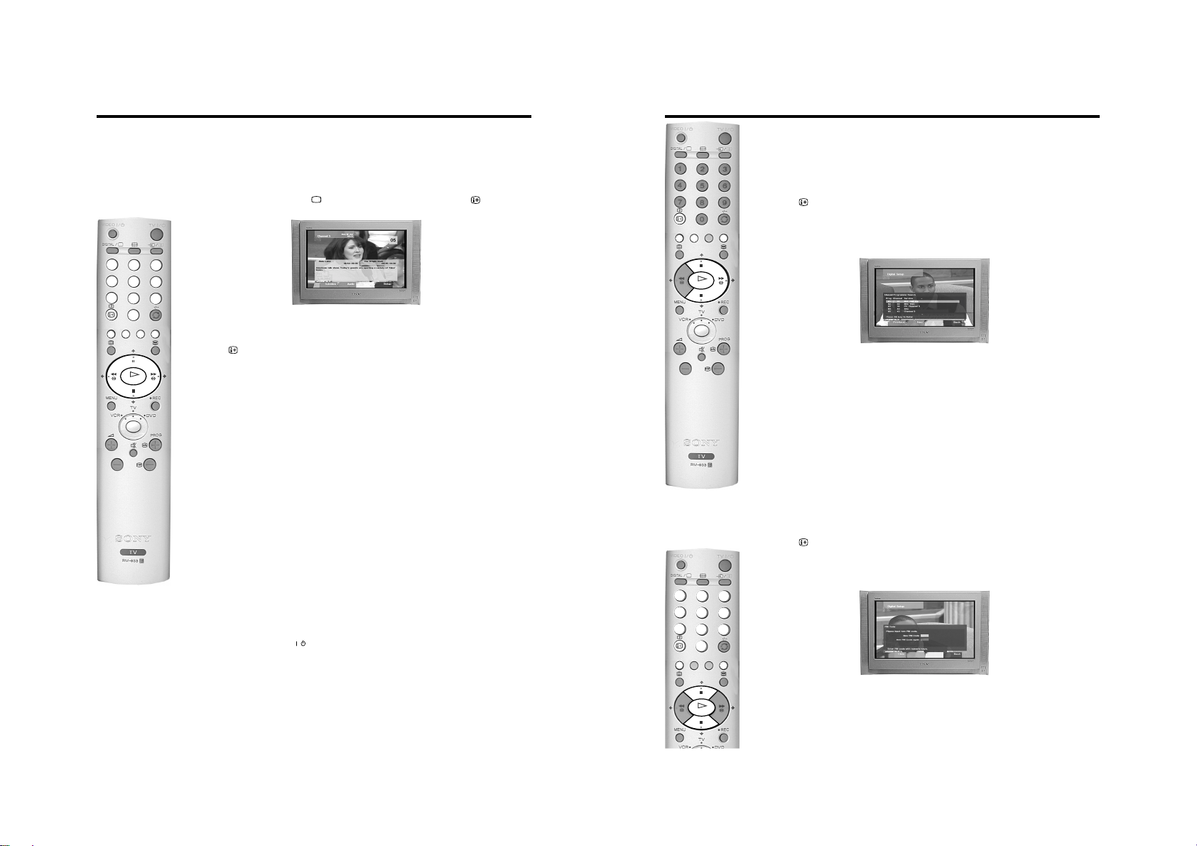
The Digital EPG menu
The EPG menu (Electronic Programme Guide) provides you with a quick and easy way to:-
a) View a complete list of the programmes available.
b) Obtain a preview of the programmes currently being broadcast.
c) Reduce the size of the list by selecting a category of programme, e.g. Sports or Movies.
d) Record programmes.
1. The EPG menu is only available when watching Digital channels. If the TV is not already in Digital
mode, press the DIGITAL/ button on the remote control. Press the button on the remote
control to display the EPG menu screen. This screen consists of an information window, a preview
window, a 2 hour timer bar ( divided into 30 minute inter vals) and a 5 channel programme li st
covering the 2 hour period.
2. Press the V or v buttons to mov e the c oloured c ursor b ar up or d ow n the p rogr amm e list a nd the b or
B buttons to move left and right. If you press the b button once more after highlighting the last
K
O
programme on the right, the programmes scheduled for the next 2 hour period are displayed.
As each programme is highlighted, a brief description of the programme appears in the event
information box at the top left of the screen.
If you do not wish to select a programme from the 5 channels listed, press the GREEN button to
display the next 5 channels or RED button to display the previous 5 channels.
3. If a programme you highlight is currentl y be ing broad ca st, press the OK button to obtain a preview in
the preview window. If you have previously set a viewing age limit in the ‘Digital Setting’ menu, and
the programme excee ds that age limit, y ou wi ll be ask ed to en ter y our PIN code before the preview is
allowed.
4. When the programme in the preview screen is the one y ou wish to w atch, pres s the OK b utton to e xit
the EPG menu and view the programme at full size.
The Category pop-up list
The ‘Category’ pop-up list allows you to quickly search for a programme by choosing from different
categories of programmes. For example, select the ‘News’ option from the ‘Category’ pop-up list to
display programme information only for News channels.
1. With the EPG menu on screen, press the YELLOW button to display the ‘Category’ pop-up list.
2. Press the V or v buttons to highlight the category you want, then press the OK button. The EPG
programme list will now only contain programmes of the type selected.
K
O
For information on the types of Ca tegories along wi th instructions on how to add and remove programm es
from the Favourite list, please refer to ‘The Channel Index menu’ section of this instruction manual.
Basic Operation
13
14 Basic Operation
VIDEO
/
TV
/
DIGITAL
1
2
3
6
5
4
7
8
9
0
- 9 -
Basic Operation
VIDEO
DIGITAL
/
K
O
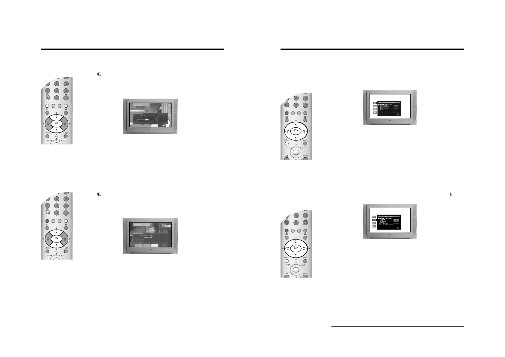
The Digital INFO display
This menu gives you information on the programmes currently being shown aswell as the those
programmes which are on next. When first s electe d, the ‘Digita l IN FO displ ay’ gives a brief description of
the current programme being transmitt ed, i ts c ha nne l nu mber and the start and end time. The title of the
next programme and its start and end time is also shown.
1. The ‘Digital INFO display’ is only available when watching Digital ch an nel s . If the TV is not already in
Digital mode, press the DIGITAL/ button on the remote control. Press the button on the
remote control to display the ‘Digital INFO display’ screen.
VIDEO
DIGITAL
TV
/
/
1
2
3
4
5
6
7
8
9
0
2. Press the b button to obtain a brief d escription of the next programme in the sc hedule. If the
programme box is blank, there is no information currently available. To return to the starting point,
press the B button repeatedly until the description for the current programme reappears.
3. Press the button on the remote control at any time to exit the ‘Digital INFO display’.
Note: To change channels while the ‘Digital INFO display’ is on screen, press the relevant numbered buttons on the
K
O
remote control.
Using other INFO menu features
Subtitles
This feature will place Digital subtitles on the screen (similar to selecting p.888 in analogue Teletext
mode).
With the ‘Digital INFO display’ on the TV screen, press the RED button to access the ‘Subtitles’ pop-up
menu. Press the V or v button to highlight the language required then press OK to select.
To remove subtitles from the TV screen, access the ‘Subtitles’ pop-up menu and select ‘Off’.
Audio
This feature allows you to listen to the broadcast in different languages*.
With the ‘Digital INFO display’ on the TV screen, press the GREEN button to access the ‘Audio’ pop-up
menu. Press the V or v button to highlight the language required then press OK to select.
REC
This feature allows you to automatically set your VCR to record the selected programme**, or have the
TV switch to the correct channel automatically when the selected programme starts.
With the ‘Digital INFO display’ on the TV screen, press the YELLOW button to access the ‘REC’ pop-up
menu. If your VCR does not have Smartlink a message is displayed reminding you to manually set your
VCR. Press the RED button to continue or press the BLUE button to return to the INFO display.
Notes: Do not switch off theTV once a programme has been set to record. If you do not wish to view the programme
being recorded, press the TV button on the remote control to switch the TV into standby mode.
When a programme has been set to record and the TV is in standby mode the standby indicator on t he front
of the TV will flash green periodically to inform you that a programme has been set to record.
Do not change channels or switch the TV to analogue mode once a programme has started rec ording or the
recording will be cancelled.
Set-up
With the ‘Digital INFO display’ on the TV screen, press the BLUE butto n to ac ce ss the ‘Ma in M enu’. The
‘Main Menu’ is explained on the following pages.
Notes: *Only when the programme is broadcast in multiple languages.
**Only for Smartlink VCRs
/
K
O
Detail Set-up
TV
/
The ‘Detail Set-up’ menu allows you to further customise your TV with the following features:
Manual Tuning
This feature allows you to select a chann el numb er from the dis played l ist and change t he digita l servic es
of that channel.
1. Press the button on the remote control to display the ‘Digital INFO display’. Press the BLUE
button to display the ‘Main Menu’.
2. Press the V or v button to highlight ‘Detail Set-up’ then press the OK button to display the ‘Detail
Set-up’ menu.
3. Press the V or v button to highlight ‘Manual Tuning’ then press the OK button to display the ‘Manual
Tuning’ menu.
4. Press the V or v button to highlight the chosen channel number for your new channel. If you do not
wish to select any of the programme numbers listed, press the RED or GREEN button to display the
previous or next 5 programme numbers on the list.
5. With your channel number highlighted, press the OK button to display the ‘Manual Programme
Search’ screen.
6. Press the V or v button if you wish to change the channel number, then press the b button to make
the select search box active.
7. Press the V or v button to begin the search process. The words ‘Searching Down’ or ‘Searching Up’
appear in the select search box to indicate that the TV is searching. If no Digital services are found
on the channel you have chosen, the channel number changes up or down automatically and the
search continues. When all services allocated to the selected channel have been found, the service
selection screen is displayed.
8. Press the V or v button to find and highlight the service you wish to allocate to the channel number
selected in Step 4, then press the OK button to display the channel selection screen.
9. Repeat Steps 4 to 8 if you wish to manually add more channels to your TV.
10. Press the BLUE button on the remote control three times to remove the ‘Digital INFO display’ from
the TV screen.
PIN Code
This feature allows you to set a 4-digit PIN code.
1. Press the button on the remote control to display the ‘Digital INFO display’. Press the BLUE
button to display the ‘Main Menu’.
2. Press the V or v button to highlight ‘Detail Set-up’ then press the OK button to display the ‘Detail
Set-up’ menu.
3. Press the V or v button to highlight ‘PIN Code’ then press the OK button to display the ‘PIN Code’
menu.
4. Enter your PIN code using the num bered b u ttons o n the r emo te con trol. If y ou ent er a wr ong n umber,
press the RED button to clear and start again.
5. Once you have entered a 4-digit code a cursor will appear in the second PIN Code box. Enter your
new PIN code once again as confirmation. Press the OK button to confirm.
6. When both PIN codes match, a message appears to inform you that your new PIN code has been
accepted. This is the PIN code you must use in future.
7. Press the BLUE button on the remote control to remove the ‘Digital INFO display’ from the TV
screen.
Note: If you have forgotten your PIN code, please use 9999. This PIN code will always be accepted.
16 Basic Operation
Advanced Operation
Advanced Operation
19
- 10 -
O
K
O
K
Advanced Operation
K
O
Software Download
Periodically Sony issues updates for the software that controls your TV. This feature allows you to
automatically receive updates free through your existing aerial.
1. Press the button on the remote control to display the ‘Digital INFO display’. Press the BLUE
button to display the ‘Main Menu’.
2. Press the V or v button to highlight ‘Detail Set-up’ then press the OK button to display the ‘Detail
Set-up’ menu.
3. Press the V or v button to highlight ‘Software Download’ then press the OK button to display the
‘Software Download’ menu.
4. Press the V or v button to change the ‘Current Setting’. If you wish to receive downloads, the
‘Current Setting’ should be set to ‘On’. If you do not wi sh to r e ce ive downl o ad s, th e ‘Current Setting’
should be set to ‘Off’.
5. Press the OK button to confirm.
6. Press the BLUE button to return to the Main menu.
7. Press the BLUE button on the remote control to remove the ‘Digital INFO display’ from the TV
screen.
System Information
This is an information screen only. It tells you th e curren t versi on of the software in you r TV togeth er with
the signal strength, as indicated by the red bar in the display.
1. Press the button on the remote control to display the ‘Digital INFO display’. Press the BLUE
button to display the ‘Main Menu’.
2. Press the V or v button to highlight ‘Detail Set-up’ then press the OK button to display the ‘Detail
Set-up’ menu.
3. Press the V or v button to highlight ‘System Information’ then press the OK button to display the
‘System Information’ menu.
Advanced Operation
The TV menu system
This TV contains a menu system which is based on a series of user friendly on-screen displays. These
displays will help you to get the most from your TV, helping you to change the picture settings, sound
settings and change the order of the TV channels.
The Picture Adjustment menu
1. Press the MENU button to display the main menu, then press the b button to enter the ‘Picture
Adjustment’ menu.
2. ‘Mode:’ is highlighted. Press the v or V button to highlight one of the options, then after pressing the
b button to activate the option press b and B or v and V buttons to adjust the setting.
3. Press the OK button to store the new setting and repeat step 2 to adjust the other options.
The Mode option has three settings for you to choose from:-
Personal: This setting allows you to adjust the Brightness, Colour, Contrast and Sharpness
Live: This is a fixed setting and is recommended for live broadcasts.
Movie: This is a fixed setting and is recommended for watching films.
4. Press the MENU button to return to normal TV operation.
Note: Highlight Reset and press OK only if you wish to return the picture to the factory preset levels.
levels to suit your personal preference.
The Sound Adjustment menu
1. Press the MENU button to display the main menu, then press the v b ut ton to high light the symbol.
Now press the b button to enter the ‘Sound Adjustment’ menu.
K
O
4. Press the BLUE button to return to the Main menu.
5. Press the BLUE button on the remote control to remove the ‘Digital INFO display’ from the TV
screen.
20 Advanced Operation
22 Advanced Operation
2. ‘Mode:’ is highlighted. Press the v or V button to highlight one of the options, then after pressing the
b button to activate the option press b and B or v and V buttons to adjust the setting.
3. Press the OK button to store the new setting and repeat step 2 to adjust the other options.
The Mode option has four settings for you to choose from:-
Personal: This setting allows you to adjust all the available options in the ‘Sound adjustment’
Rock: This is a fixed setting and is recommended for rock soundtracks.
Pop: This is a fixed setting and is recommended for pop soundtracks.
Jazz: This is a fixed setting and is recommended for jazz soundtracks.
Note: ‘Tre ble’ and ‘Bass’ settings can only be altered when the ‘Mode’ option is set to Personal.
4. When ‘Detail Ad justment’ is highlighted, press the b button to display the ‘Detail Adjustment’ sub
menu. This menu gives you a further three options to choose from.
menu to suit your personal preference.
continued...
- 11 -
O
K
O
K
O
K
Advanced Operation
5. Highlight and activate one of the options using the v and b buttons, then press the v or V buttons to
set the option to On or Off. See the table below for an explanation of each option and their effects.
6. Press the OK button to store the new setting, then repeat step 5 to alter the other options.
7. Press MENU button to return to normal TV operation.
Dolby* Virtual When set to ‘On’, the TV simulates the effects of Dolby Pro Logic Surround sound.
Auto Volume When set to ‘On’, the volume level will remain constant even if the broadcast level
TV Speakers Set to ‘Off’ if you wish to conne ct an ex ternal am plifier to the audi o output sockets on
• Notes on the Sound Adjustment menu
• Highlight ‘Reset’ and press OK only if you wish to return the sound settings to their factory preset levels.
• When receiving a bilingual broadcast set the ‘Dual Sound’ option to ‘A’ for channel 1 sound, ‘B’ for channel 2 sound or ‘Mono’ if the mono
channel is available for selection. When receiving a stereo broadcast the ‘Dual Sound’ option can be set to Stereo or Mono.
* This TV has been designed to create a Virtual Dolby Surround sound effect from a ‘Dolby Pro Logic Surround’ broadcast without the need for
additional speakers. However, you can connect an external amplifier to this TV if desired (see ‘Connecting additional equipment’ section of
this manual).
* Manufactured under licence from Dolby Laboratories. ‘Dolby’, ‘Pro Logic’ and the double-D symbol are trademarks of Dolby Laboratories.
Note: If you connect headphones to this TV or if you set the ‘Auto Volum e’ option to ‘On’,
‘Dolby Virtual’ will automatically be set to Off.
should change, i.e. during commercial breaks.
Note: This option automatically sets itself to ‘Off’ when ‘Dolby Virtual’ is set to ‘On’.
the rear of the TV.
The Timer menu
The ‘Sleep Timer’ allows you to select a period of time after which the TV automatically switches itself
into standby mode.
1. Press the MENU button to display the main menu. Use the v or V button to highlight the symbol.
Press the b button twice to highlight ‘Off’ in the ‘SleepTimer’ menu.
Advanced Operation
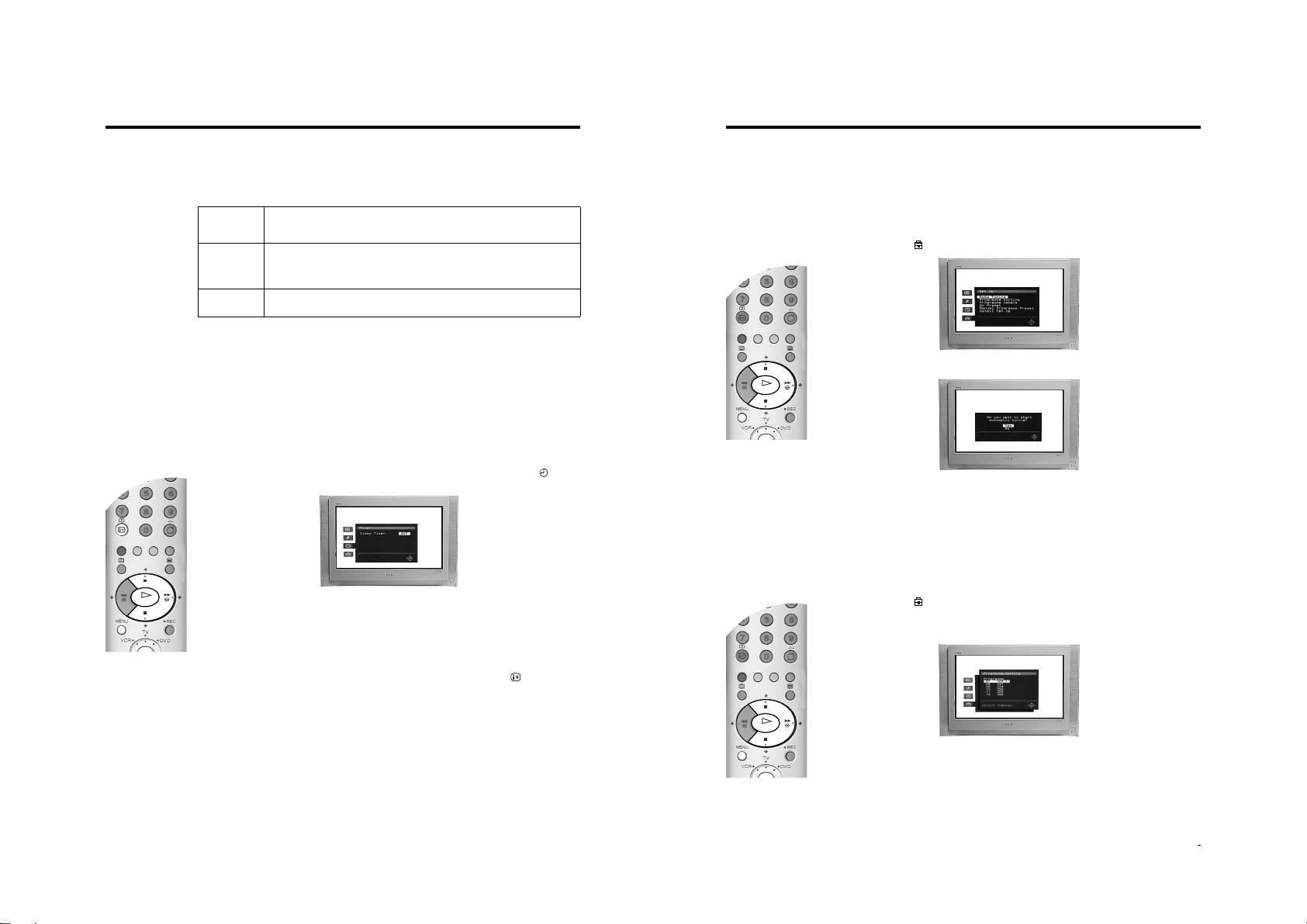
The Set Up menu
The ‘Set Up’ menu contains many features that enable you to customise your TV. The following pages
explain all of the features contained in the ‘Set Up’ menu.
Auto Tuning
The TV automatically tuned in all the available channels when you first installed the TV. Follow these
instructions if you wish to re-install y our TV at an alternative l ocation or s earch for ne w channels that have
been subsequently launched by broadcasters.
1. With the TV in analogue mode, press the MENU button to display the main menu. Press the v or V
button to highlight the symbol, then press the b button to enter the ‘Set Up’ menu.
2. Press the v or V buttons to highlight ‘Auto Tuning’ then press the b button to confirm. The autotune
prompt display appears on screen.
3. Press the OK button to select ‘Yes’ and begin the autotune procedure.
Whilst tuning is taking place, the search and store display appears on screen.
When all availab le s ignals ha v e be en cap tured an d stored , the di spla y is rem oved and the TV returns
to normal operation.
Notes: You can cancel the tuning at any time by pressing the MENU button.
Programme Sorting
2. Press the v or V buttons to set the amount of time before the TV switches itself into standby. This
can be in 15 minute intervals up to a maximum of 4 hours.
3. Press the OK button to store.
4. Press the MENU button to return to normal TV operation. One minute before the TV switches into
standby, the time remaining is counted down on screen.
Note: In analogue mode you can check the time remaining until standby by pressing the button. The time
remaining is displayed in the bottom left corner of the TV screen.
Advanced Operation
23
24 Advanced Operation
You can use this feature to change the order in which the analogue channels are stored on your TV.
1. With the TV in analogue mode, press the MENU button to display the main menu. Press the v or V
button to highlight the symbol, then press the b button to enter the ‘Set Up’ menu.
2. Press the v or V buttons to highlight ‘Progra mme Sorti ng’ then press the b button to display the
Programme Sorting menu on screen.
3. Press the v or V button to highlight the channel you wish to move to a new position, then press the
OK button.
4. Press the v or V button to highlight the new channel number for your channel, then press the OK
button.
5. Repeat steps 3 and 4 to move other channels if required, then press the MENU button to return to
normal TV operation.
- 12 -
Additional Information
Remote control of connected equipment
This remote control can operate not only Sony DVDs and VCRs, but also those made by other
manufacturers. The following instructions will guide you through the set up procedure.
VIDEO
DIGITAL
/
1
2
4
5
7
8
0
1. Find the 3 digit code for your brand from the list below.
TV
/
2. Press the Media Select button on the remote control until either the green VCR light is illuminated
OR the green DVD light is illuminated.
3. Whilst the required green light is illuminated, press and hold down the YELLOW button for
3
approximately 6 seconds, until the light starts to flash.
6
4. Use the numbered buttons to enter t he 3 di git cod e for your DVD or VCR. Once a corre ct n umber has
been entered, all three green lights will illuminate momentarily.
9
5. Turn on your DVD or VCR and check that the remote control operates the main functions. If not,
repeat steps 2 - 4 and enter the next 3 digit code allocated to your brand of VCR or DVD.
6. When you wish to use the remote control to operate the TV again, press the Media Select button
until the TV green light illuminates. Don’t forget to select VCR or DVD using the Media Select button
every time you wish to operate that equipment with this remote control.
Note: The brand codes you set may be lost if weak batteries are not replaced immediately. Should this happen, use
the above procedure to re-enter the code. A small label has been attached to the inside of the battery cover
for you to make a note of your brand codes. Not all brands and models of DVDs or VCRs are covered in this
list, however, Sony will endeavour to update the software periodically. Please refer to the code table provided
with your remote control.
VCR Brand List DVD Brand List
Brand Code Brand Code
SONY (VHS) 301, 302, 303, 309 SONY 001
SONY (BETA) 303, 307, 310 AIWA 021
SONY (DVD) 304, 305, 306 DENON 018, 027, 020, 002
AIWA 325, 331, 351 GRUNDIG 009, 028, 023, 024, 016, 003
AKAI 326, 329, 330 HITACHI 025, 026, 015, 004
DAEWOO 342, 343 JVC 006, 017
GRUNDIG 358, 355, 360, 361, 320, 351 KENWOOD 008
HITACHI 327, 333, 334 LG 015, 014
JVC 314, 315, 322, 344, 352, 353,
354, 348, 349
LG 332, 338 MATSUI 013, 016
LOEWE 358, 355, 360, 361, 320, 351 ONKYO 022
MATSUI 356, 357 PANASONIC 018, 027, 020, 002
ORION 328 PHILIPS 009, 028, 023, 024, 016, 003
PANASONIC 321, 323 PIONEER 004
PHILIPS 311, 312, 313, 316, 317, 318,
SAMSUNG 339, 340, 341, 345 SANYO 007
SANYO 335, 336 SHARP 019, 027
SHARP 324 THOMSON 012
THOMSON 319, 350 TOSHIBA 003
TOSHIBA 337 YAMAHA 018, 027, 020, 002
358, 359
LOEWE 009, 028, 023, 024, 016, 003
SAMSUNG 11, 14
Additional Information
Troubleshooting
Here are some simple soloutions to problems which may affect the picture and sound.
Problem Cause
No picture, no sound.
Poor or no picture (screen is dark), but good sound.
No Digital channels after tuning.
Some channels are blank.
Standby indicator flashing.
Good Picture, no sound.
Poor picture quality.
No colour on colour programmes.
Remote control does not function.
Distorted picture when changing programmes or selecting
Teletext.
Cause Solution
TV in standby.
Aerial disconnected.
Picture level adjustment.
No Digital transmissions in your area.
No Digital transmissions from th e trans mitter you are curren tly
using.
Unsuitable aerial.
Weak signal.
Scrambled/subscription-only channel.
Programme information without picture or sound.
Fault.
Volume control.
TV speakers turned off
Wrong external mode selected.
Colour level setting.
• If you continue to have these problems, have your TV serviced by qualified
personnel or you can contact the Sony UK Digital HelpLine on 0870 600 1717.
• NEVER open the casing yourself.
• Power off.
• TV in standby.
• Aerial disconnected.
• Picture preset level adjustment.
• No digital transmissions in your area.
• No digital transmissions from the transmitter you are
currently using.
• Weak signal.
• Unsuitab le aerial.
• Scrambled/subscription-only channel.
• Programme used only for data (no picture or sound).
• Programme not being transmitted.
• Digital mode Timer Record active (regular flash).
• Fault (irregular flash).
• Volume control.
• TV speakers turned off.
• Headphones are connected.
• Wrong external mode selected on an RGB video source.
• Colour level setting.
• Batteries low. Media Selector set to wrong mode for the
equipment in use.
• Inputs from external equipment not switched off.
• Plug in the TV.
• Press the button on the front of the TV.
• If the indicator is o n p re ss th e button or a numbered
button on the remote control.
• Check the aerial connection.
• Select on the TV menu system then adjust the
brightness, picture and colour balance levels.
• Contact a local installer to find out when digital
transmissions begin in your area.
• Contact a local installer to find out at which transmitter
you should be pointing your aerial.
• Change your aerial to cover the channels used by digital
programmes. (Contact a local installer)
• Ensure aerial is correctly align ed to tra ns mi tter.
• Ensure aerial is plugged directly into the TV (not through
other equipment).
• Upgrade to a higher gain aerial.
• Subscribe to pay-per-view broadcaster.
• See ‘Skipping a programme’ section of this manual.
• See ‘Programm e Sorting’ section of this manual.
• Do not open the cabinet, refer to qualified personnel.
• Contact your nearest Sony Service Centre.
• Press the + button on the remote control.
• Refer to ‘The Sound menu’ section in this manual
• If is displayed on the screen, press the button on the
remote control.
• Disconnect headphones.
• Press the button repeatedly until the RGB symbol is
displayed on screen.
• Select on the TV menu system then adjust the colour
setting.
/
32 Additional Information
34 Additional Information
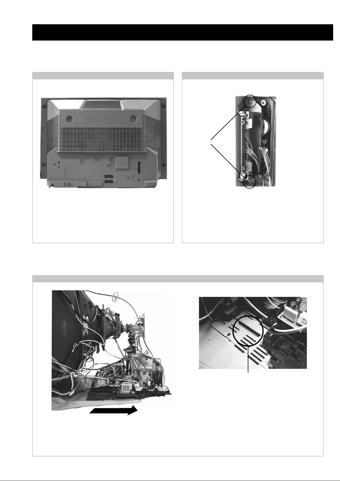
SECTION 2 DISASSEMBLY
2-1. Rear Cover Removal 2-2. Side Control Module Removal
<=
<=
=>
=>
=>
Remove the rear cover fixing screws indicated and withdraw
the rear cover from the beznet.
<=
<=
<=
<=
Screws
<=
Remove the two screws fixing the user control module to the
side of the set. The control module can then be removed by
sliding it towards the rear of the set allowing access to the H2
Board.
2-3. Chassis Removal and Refitting
T o remove lift the main bracket rear slightly and slide the
chassis away from the beznet. Ensure that the interconnecting
leads are released from their purse locks to prevent damage
being caused.
When refitting the chassis ensure that the main
bracket is located in the beznet guide slots before
sliding the chassis forwards. Refit the
interconnecting leads in their respective purse locks.
- 13 -
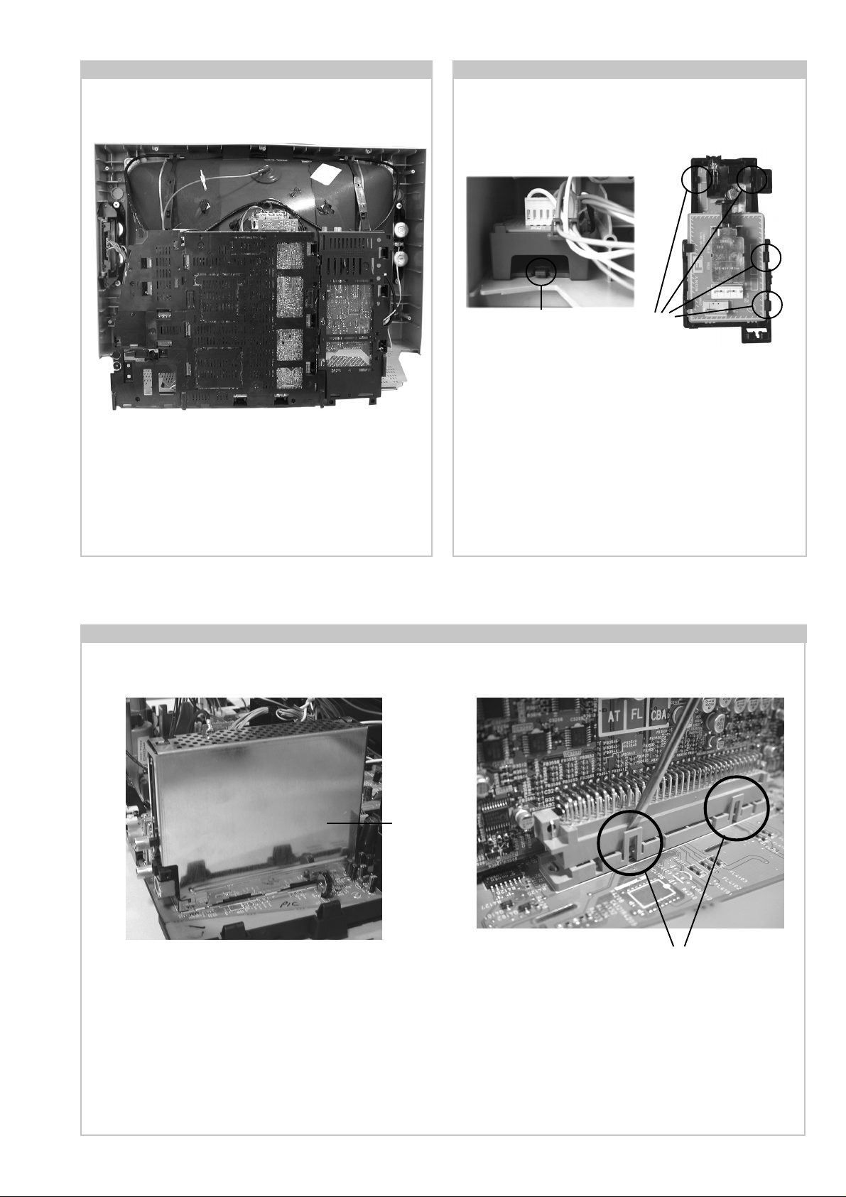
2-4. Service Position
2-5. F6 and H8 Board Removal
Position the chassis as indicated to access the solder side
of the PWB’s. T o gain access to the A Board follo w the
instructions on page 16. [Removal and Replacement of the
main bracket bottom plates ].
2-6. N Board Removal
Clip
Clips
Release the clip circled and pull the F6 bracket towards the
rear of the set. The bracket can then be removed to allow
access to the boards.
T o remove the F6 and H8 Boards release the clips circled and
ease the boards gently away from the support bracket.
Shield
case
Clips
Remove the shield case by pulling vertically until it is clear of the N Board. Release the N board socket retaining clips, circled, by
gently prising them with a screwdriver and carefully lift the N Board v ertically .
- 14 -

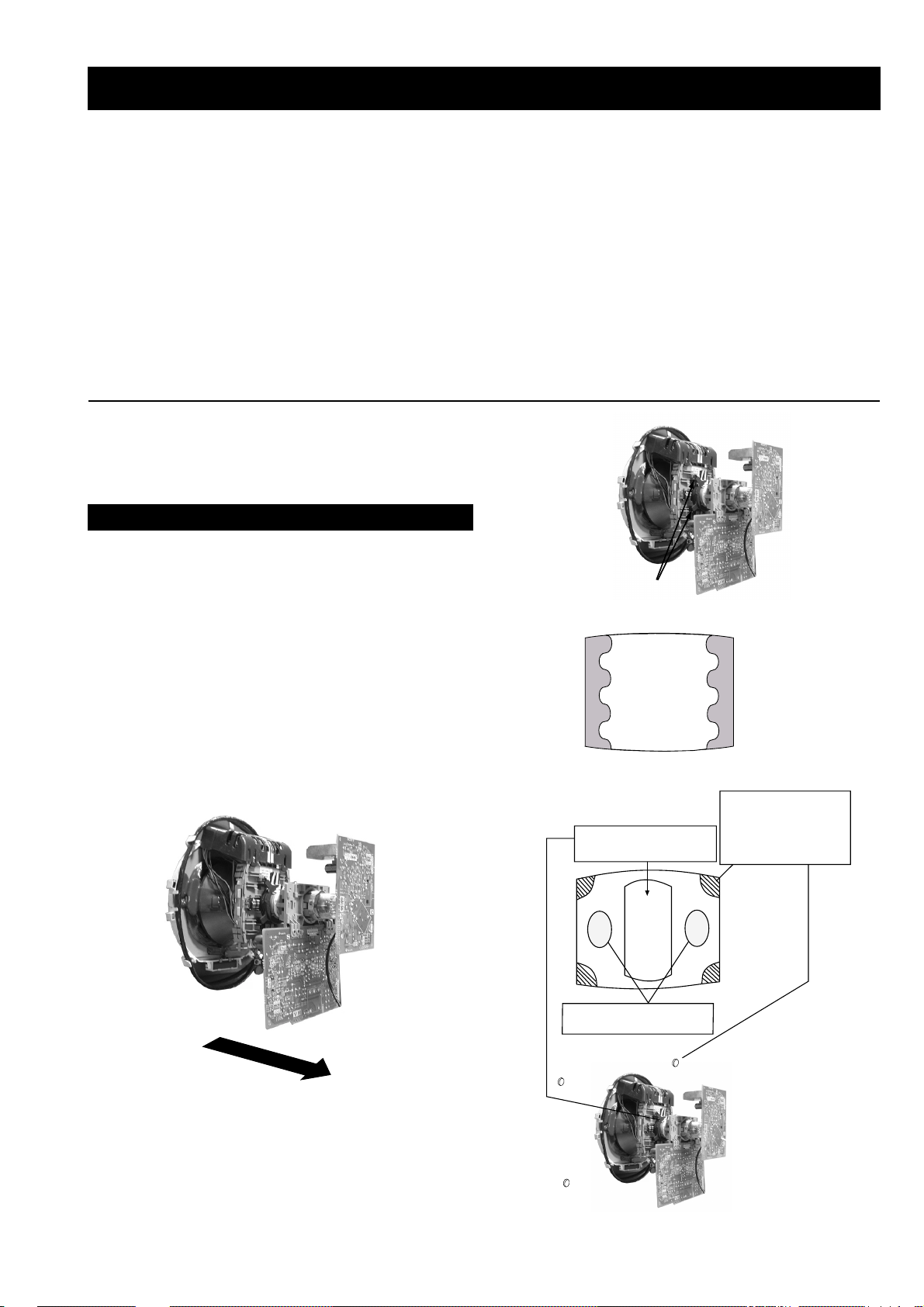
2-7. Picture Tube Removal
WARNING:
BEFORE REMOVING
THE ANODE CAP
High voltage remains in the CRT even
after the power is disconnected. To
avoid electric shock, discharge CRT
before attempting to remove the anode
cap. Short between anode and CRT
coated earth ground strap.
Coated Earth
Ground Strap
8
10
9
1
3
7
2
6
5
4
1. Discharge the anode of the CRT and remove the anode cap.
2. Unplug all interconnecting leads from the Deflection yoke, neck
assy, de gaussing coils and CRT grounding strap.
3. Remov e the C Board from the CR T.
4. Remov e the chassis assembly .
5. Loosen the Neck assembly fixing screw and remove.
6. Loosen the Deflection yoke fixing screw and remove.
7. Place the set with the CRT face down on a cushion and remove
the Degaussing Coil holders.
8. Remove the Degaussing Coils.
9. Remov e the CR T grounding strap and spring tentioners.
10. Unscrew the four CRT fixing scre ws [ located on each CRT
corner ] and remove the CR T .
[T ake care not to handle the CR T by the neck.]
Removal of the Anode-Cap
* REMOVING PROCEDURES.
a
1
Turn up one side of the rubber cap in
the direction indicated by the arrow a
b
2 Using a thumb pull up the rubber cap
firmly in the direction indicated by the
arrow b
How to handle the Anode-Cap
1. To prevent damaging the surface of the anode-cap do not use
sharp materials.
2. Do not apply too great a pressure on the rubber, as this may cause
damage to the anode connector.
3. A metal fitting called a shatter hook terminal is fitted inside the
rubber cap.
4. Do not turn the rubber foot over excessively, this may cause
damage if the shatter hook sticks out.
c
b
Anode button
3 When one side of the rubber cap is
separated from the anode button, the
anode-cap can be removed by turning
up the rubber cap and pulling it up in
the direction of the arrow c
- 15 -

REMOV AL AND REPLA CEMENT OF THE MAIN-BRA CKET
BOTT OM PLA TES.
For safety reasons, on no account should the plates be removed and not refitted after servicing.
(1) REMOVING THE PLATES
In the event of servicing being required to the solder side of the D Board printed wiring board, the
bottom plates fitted to the main chassis bracket require to be removed.
This is performed by cutting the gates with a sharp wire cutter at the locations indicated by the
arrows.
Note : There are 3 plates fitted to the main bracket and secured by3 gates.
Only remove the necessary plate to gain access to the printed wiring board.
- 16 -
(2) REFITTING THE PLATES
Because the plates differ in size it is important that the correct plates are refitted in their original
location.
Please note that the plates need to be rotated 180 degrees from their cut position to allow the tabs to
be fitted into their catch positions.
Catch
Tab
SECTION 3 SET -UP ADJUSTMENTS
• When complete readjustment is necessary or a new picture
tube is installed, carry out the following adjustments.
• Unless there are specific instructions to the contrary , carry
out these adjustments with the rated power supply .
• Unless there are specific instructions to the contrary, set the
controls and switches to the following settings :
Contrast .................... 80% [or remote control normal]
Brightness................... 50%
Preparation:
1. In order to reduce the influence of geomagnetism on the
set’s picture tube, face it in an easterly or westerly direction.
2. Switch on the set’s power and degauss with the degausser.
3-1. Beam Landing
1. Input an all white signal from the pattern generator. Set the
Contrast and Brightness to normal.
2. Set the pattern generator raster signal to Red.
3. Move the deflection yoke forward and adjust with the
purity control so that the Red is at the centre and the Blue
and Green take up equally sized areas on each side of the
screen. [See Fig.3-1 - 3-3].
4. Move the deflection yoke backwards and adjust so that the
entire screen becomes Red. [See Fig.3-1]
5. Switch the raster signal to Blue, then to Green and verify
the condition.
6. When the position of the deflection yoke has been
determined, fasten the deflection yoke with the screws.
7. If the beam does not land correctly in all the corners, use a
magnet to correct it. [See Fig.3-4]
Carry out the adjustments in the following order :
3-1. Beam Landing.
3-2. Convergence.
3-3. Focus.
3-4. White Balance.
Note : T est equipment required.
1. Color bar/pattern generator.
2. Degausser.
3. Oscilloscope.
4. Digital multimeter.
Fig. 3-2.
Purity
Fig. 3-3.
GREEN
RED
BLUE
Disk magnets or
rotatable disk
Purity control corrects
this area
magnets correct
these areas (a-d)
Fig. 3-1.
Caution :
High voltages are present on the Deflection yoke terminals
- take care when handling the Deflection yoke whilst carrying
out adjustments.
- 17 -
Disk Magnets
Fig.3-4
a
cd
Deflection yoke positioning
corrects these areas
b
GBR
GBR
GBR
G
B
R
GBR
G
B
R
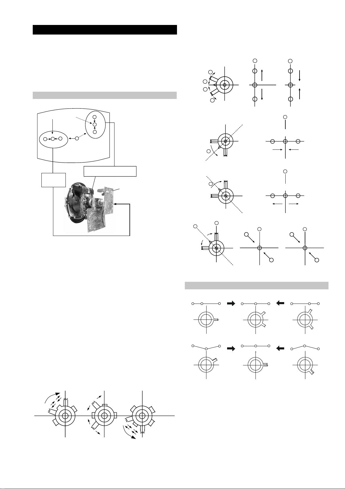
3-2. Con vergence
B
G
R
a
b
R
G
B
b
a
Preparation:
4. If the V.STAT magnet is moved in the direction of the (a)
and (b) arrows, the Red, Green and Blue points move as
indicated below .
• Before starting this adjustment, adjust the focus, horizontal
size and vertical size.
• Minimize the Brightness setting.
• Input a dot pattern from the pattern generator.
Horizontal and Vertical Static Convergence
Center dot
R
G
B
H STAT
convergence
control
R
G
B
V.STAT Vertical Static Magnet
C Board
RV702 (H STAT)
H STAT Convergence
(on mount side)
a
b
a
a
b
a
b
B
G
R
R
R
b
B
G
R
a
B
G
b
B
G
Fig.3-5
1. [Moving horizontally], adjust the H.STAT control so that
the Red, Green and Blue points are on top of each other at
the centre of the screen.
Operation of the BMC (Hexapole) magnet.
2. [Moving v ertically], adjust the V .STAT magnet so that the
Red, Green and Blue points are on top of each other at the
centre of the screen.
3. If the H.STAT variable resistor is unable to bring the Red,
Green and Blue points together at the centre of the screen,
adjust the horizontal convergence with the H.STAT variable
resistor and the V.STAT magnet in the manner indicated
below.
[In this case, the H.ST AT variable resistor and the V.STA T
magnet influence each other].
• Tilt the V.ST AT magnet and adjust the static convergence by
opening or closing the V.STA T magnet.
The movement of the magnets interact with each other and so
the respective dot position should be monitored while carrying
out this adjustment.
Use the H.STA T VR to adjust the Red, Green and Blue dots so
that they coincide at the centre of the screen
(by moving the dots in the horizontal direction).
- 18 -

+
YCH VR
Deflection Yoke
+
+
Geometry Adjustment.
Preparation:
Before starting this adjustment, adjust the horizontal and
vertical static convergence.
1. Remove the deflection yoke spacer.
2. Tilt the deflection yoke as indicated in the figure below and
optimise the geometry.
Tilting the D Y Up and Down will balance the upper and
lower pin adjustment.
Tilting the D Y Left and Right will balance the H-Trap
adjustment.
3. Re-install the deflection yoke spacer.
YCH Adjustment
TL V Adjustment
+
+
TLV VR
+
Deflection Yoke
Screen Corner Convergence
If you are unable to adjust the corner conver gence properly ,
this can be corrected with the use of permalloy magnets.
HTIL Adjustment
Tilt Direction
Deflection Yoke
TLH pieces
a
a-d: screen-corner
convergence defect
c
Install the permalloy assembly
for the area that needs correcting.
b
b
d
a
HTIL correction can be performed by adding a TLH correction
assembly to the Deflection yoke.
Permalloy Assy
X-4387-214-1
- 19 -
d
Convergence adjustment with permalloy
c
 Loading...