

Sony KD-32DX100U, KD-32NS100B, KD-32NX100U Service Manual
SERVICE MANUAL
AE-6D
CHASSIS
MODEL
COMMANDER DEST CHASSIS NO.
KD-32DX100U
KD-32NS100B
RM-933 UK SCC-Q84B-A
RM-935 FR SCC-Q85A-A
MODEL
COMMANDER DEST CHASSIS NO.
KD-32NX100U
RM-935 UK SCC-Q84A-A
KD-32DX100
RM-933
KD-32NX100/KD-32NS100 RM-935
- 1 -

TABLE OF CONTENTS
Section Title Page Section Title Page
Caution .................... 3
Specifications .................... 4
Connectors .................... 5
Self Diagnostic Software .................... 6
4. CIRCUIT ADJUSTMENTS
4-1. Electrical Adjustments .................... 24
4-2. Volume Electrical Adjustments .................... 27
4-3. Test Mode 2 .................... 28
1. GENERAL
Automatically Tuning the TV .................... 9
Finding your Video Channel .................... 9
Using a Digital Text Service .................... 9
Using a Conventional
Text Service .................... 10
Using the Programme Index
Table .................... 11
Adjusting the Sound .................... 11
Adjusting the Picture Rotation .................... 12
Setting your Personal ID .................... 12
Manually Tuning Analogue
Signals .................... 12
Remote Control Configuration
for VCR/DVD .................... 13
Troubleshooting .................... 13
2. DISASSEMBLY
2-1. Rear Cover Removal (Step 1) .................... 14
2-2. Rear Cover Removal (Step 2) .................... 14
2-3. Rear Cover Removal (Step 3) .................... 14
2-4. Speaker Disconnection .................... 14
2-5. Chassis Removal .................... 15
2-6. Service Position .................... 15
2-7. D and G Board Removal .................... 15
2-8. G1 Bracket Removal .................... 16
2-9. F1 Board Removal .................... 16
2-10. H1 Board Removal .................... 16
2-11. Removal of N Board Shield .................... 16
2-12. Picture Tube Removal .................... 17
Bottom Plates .................... 18
Removing the Glass Panel .................... 19
3. SET-UP ADJUSTMENTS
3-1. Beam Landing .................... 20
3-2. Convergence .................... 21
3-3. Focus Adjustment .................... 23
3-4. Screen (G2), White Balance .................... 23
ATTENTION
5. DIAGRAMS
5-1. Block Diagrams (1) .................... 29
Block Diagrams (2) .................... 30
Block Diagrams (3) .................... 31
Block Diagrams (4) .................... 32
Block Diagrams (5) .................... 33
Block Diagrams (6) .................... 34
Block Diagrams (7) .................... 35
Block Diagrams (8) .................... 36
5-2. Circuit Board Location .................... 36
5-3. Schematic Diagrams and
Printed Wiring Boards .................... 36
* A Board .................... 37
* M3 Board .................... 42
* J1 Board .................... 45
* B4 Board .................... 46
* F Board .................... 53
* F1 Board .................... 53
* F3 Board .................... 53
* H2 Board .................... 53
* G Board .................... 54
* D Board .................... 56
* C Board .................... 58
* N1 Board .................... 58
* G1 Board .................... 61
* H5 Board .................... 61
* H6 Board .................... 61
* VM Board .................... 61
5-4. Semiconductors .................... 63
5-5. IC Blocks .................... 66
6. EXPLODED VIEWS
6-1. Chassis (KD-32DX100U) .................... 68
6-2. Picture Tube (KD-32DX100U) ................... 69
6-3. Chassis (KD-32NX/NS100) .................... 70
6-4. Picture Tube (KD-32NX/NS100) ................. 71
6-5. Modem (KD-32NS100B) .................... 72
7. ELECTRICAL PARTS LIST .................... 73
APRES AVOIR DECONNECTE LE CAP DE’LANODE,
COURT-CIRCUITER L’ANODE DU TUBE CATHODIQUE ET
CELUI DE L’ANODE DU CAP AU CHASSIS METALLIQUE DE
L’APPAREIL, OU AU COUCHE DE CARBONE PEINTE SUR LE
TUBE CATHODIQUE OU AU BLINDAGE DU TUBE
CATHODIQUE.
ATTENTION !!
AFIN D’EVITER TOUT RISQUE D’ELECTROCUTION
PROVENANT D’UN CHÁSSIS SOUS TENTION, UN
TRANSFORMATEUR D’ISOLEMENT DOIT ETRE UTILISÈ LORS
DE TOUT DÈPANNAGE LE CHÁSSIS DE CE RÈCEPTEUR EST
DIRECTMENT RACCORDÈ Á L’ALIMENTATION SECTEUR.
ATTENTION AUX COMPOSANTS RELATIFS Á
LA SECURITÈ!!
LES COMPOSANTS IDENTIFIÈS PAR UNE TRAME ET PAR UNE
MARQUE SUR LES SCHÈMAS DE PRINCIPE, LES VUES
EXPLOSÈES ET LES LISTES DE PIECES SONT D’UNE IMPOR-
TANCE CRITIQUE POUR LA SÈCURITÈ DU FONCTIONNEMENT,
NE LES REMPLACER QUE PAR DES COMPSANTS SONY DONT
LE NUMÈRO DE PIÈCE EST INDIQUÈ DANS LE PRÈSENT
MANUEL OU DANS DES SUPPLÈMENTS PUBLIÈS PAR SONY.
CAUTION
SHORT CIRCUIT THE ANODE OF THE PICTURE TUBE AND THE
ANODE CAP TO THE METAL CHASSIS, CRT SHIELD, OR THE
CARBON PAINTED ON THE CRT, AFTER REMOVAL OF THE
ANODE CAP.
WARNING !!
AN ISOLATION TRANSFORMER SHOULD BE USED DURING
ANY SERVICE WORK TO AVOID POSSIBLE SHOCK HAZARD
DUE TO LIVE CHASSIS, THE CHASSIS OF THIS RECEIVER IS
DIRECTLY CONNECTED TO THE POWER LINE.
SAFETY-RELATED COMPONENT WARNING !!
COMPONENTS IDENTIFIED BY SHADING AND MARKED
THE SCHEMATIC DIAGRAMS, EXPLODED VIEWS AND IN THE
PARTS LIST ARE CRITICAL FOR SAFE OPERATION. REPLACE
THESE COMPONENTS WITH SONY PARTS WHOSE PART
NUMBERS APPEAR AS SHOWN IN THIS MANUAL OR IN
SUPPLEMENTS PUBLISHED BY SONY.
- 2 -
ON
CAUTION
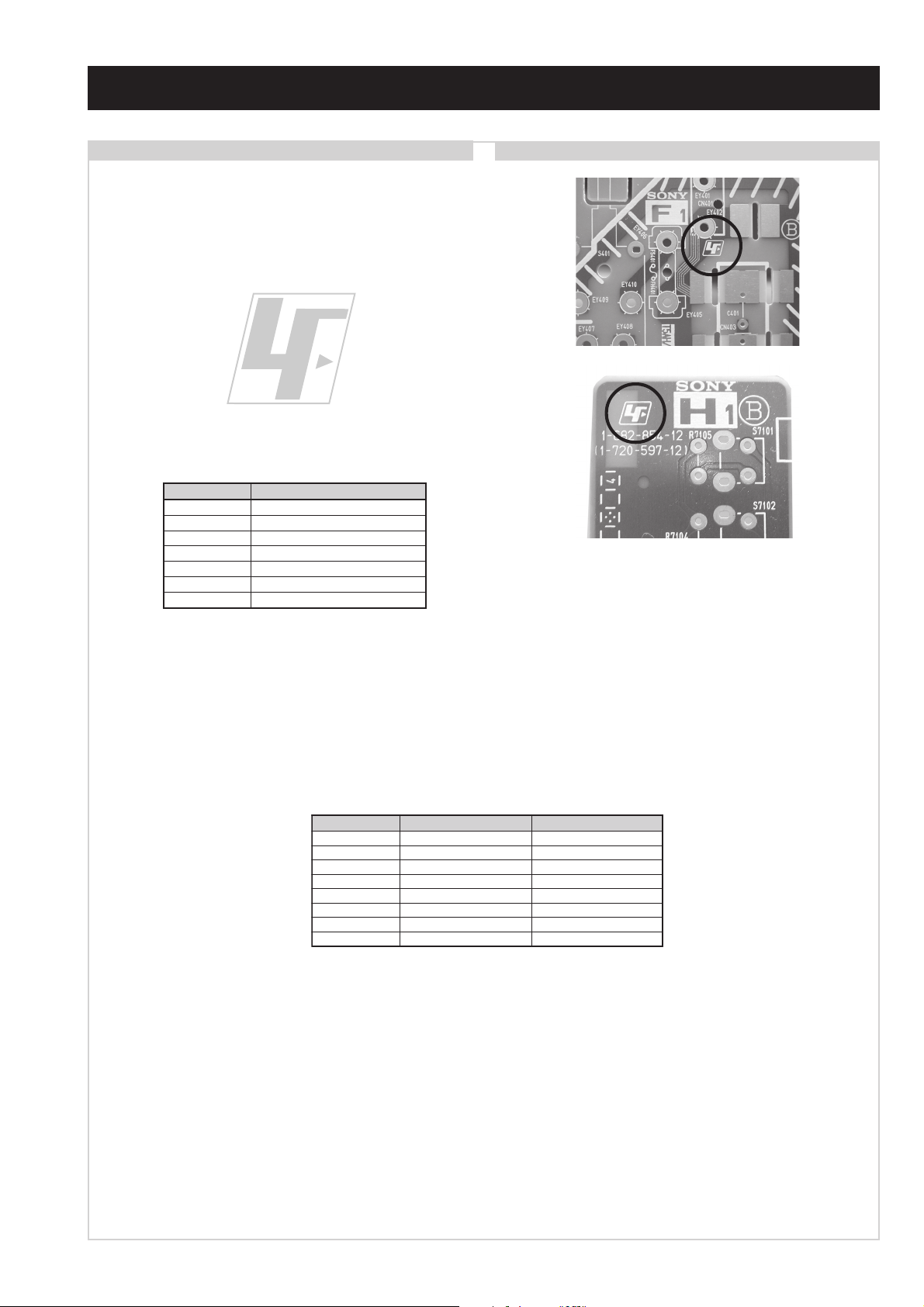
Lead Free Soldered Boards
The circuit boards listed below [Table 1] used in these models
may have been processed using Lead Free Solder. The boards are
identified by the LF logo located close to the board designation
e.g. F1, H1 etc [ see examples ]. The servicing of these boards
requires special precautions to be taken as outlined below.
Table 1
draoB noitcnuF
CevirDTRCB,G,R
FesuF/gninethgiL
1FtupnICA
1HonohPdnaSHVS
2HscriC
3HrekaepS
MVnoitaludoMyticoleV
example 1
example 2
It is strongly recommended to use Lead Free Solder material in order to guarantee optimal quality of new solder joints. Lead Free Solder
is available under the following part numbers :
rebmuntraP retemaiD skrameR
91-500-046-7mm3.0gK52.0
02-500-046-7mm4.0gK05.0
12-500-046-7mm5.0gK05.0
22-500-046-7mm6.0gK52.0
32-500-046-7mm8.0gK00.1
42-500-046-7mm0.1gK00.1
52-500-046-7mm2.1gK00.1
62-500-046-7mm6.1gK00.1
Due to the higher melting point of Lead Free Solder the soldering iron tip temperature needs to be set to 370 degrees centigrade. This
requires soldering equipment capable of accurate temperature control coupled with a good heat recovery characteristics.
For more information on the use of Lead Free Solder, please refer to http://www.sony-training.com
- 3 -
LEDOMMETI metsySnoisiveleT metsySoeretS egarevoClennahC metsySroloC
B
UT-BVD,IoeretSMACIN96E-12E:FHUI
,L,I,K/D,H/G/B
S-BVD
MACIN/NAMREG
oeretS
01F-2F,21E-2E:FHV
01U-1U
14S-12S:REPYH
96B-12B,96F-12F,96E-12E:FHU
MACES,LAP
01M-1M,50S-10S,14S-1S:VTELBAC
,)NIOEDIV(
MACES,LAP
)NIOEDIV(
85.3CSTN,34.4CSTN
LM@PM2GEPM
85.3CSTN,34.4CSTN
LM@PM2GEPM
ebuTerutciP
rotcennocoruEnip-12:1
)dradnatsCELENEC(
rotcennocoruEnip-12:2
rotcennocoruEnip-12:3
skcaJonohP
tekcoSAICMCP
kcajenohpdaeHkcajinimoerets
stupnioiduAskcajonohp
stupnioediVskcajonohp
tupnioediVSNIDnip4
nortinirTDF
)sehcni23(mc28xorppA
derusaemerutcipmc67xorppA(
)yllanogaid
noitcelfedeerged°201
]RAER[slanimreTtuptuO/tupnI snoitacificepSlareneG
.slangisoediVdnaoiduArofstupnI
.BGRrofstupnI
oiduAdnaoediVVTfostuptuO
.slangis
.slangisoediVdnaoiduArofstupnI
.BGRrofstupnI
oiduAdnaoediVVTfostuptuO
.slangis
.slangisoediVdnaoiduArofstupnI
.oediVSrofstupnI
slangisoiduAdnaoediVrofstuptuO
)elbatceles(
oiduArofelbairavsrotcennoCtuptuO
slangiS
eludoMsseccAlanoitidnoC
]EDIS/TNORF[slanimreTtuptuO/tupnI lortnocderarfnI:metsyslortnocetomeR
tuptuOdnuoS
rekaepstfeLdnathgiR
refoowbuS
stnemeriuqeRrewoPV042-022
noitpmusnoCrewoPW031
snoisnemiDmm295x026x688xorppA
thgieWgk47xorppA
seirosseccAdeilppuS
serutaeFrehtO
stnemeriuqerrewoP
)SMR(W01x2)rewoPcisuM(W02x2
)SMR(W51x1)rewoPcisuM(W03x1
)U001XD23-DK(rednammoCetomeR339-MR
etomeR539-MR)U001XN23-DK(rednammoC
)B001SN23-DK(
)2(yrettab6RdetangisedCEI
)U001XN23-DK(elbachguorhtpooLFR
)U001XD23-DK(
)B001SN23-DK()09.V(medoMlanretxE
,kniltramS,txeteleT,CRD,erutcipzH001
ybloDlautriV
cdV3
noitangisedCEIseirettab2
)AAezis(6R
metI
emaNledoM
bmoClaPNONONO
PIPFFOFFOFFO
ytiroirPBGRNONONO
xoBrefooWNONONO
1tracSNONONO
2tracSNONONO
3tracSNONONO
)4(nitnorFNONONO
rotcejorPFFOFFOFFO
9:61niBKA
edom
G/BmroNFFOFFONO
ImroNNONONO
K/DmroNFFOFFONO
SUAmroNFFOFFOFFO
LmroNFFOFFONO
TASmroNFFOFFONO
MmroNFFOFFOFFO
txeteleTNONONO
oeretSmaciNNONONO
U001XD23-DK U001XN23-DK B001SN23-DK
NONONO
.ecitontuohtiwegnahcottcejbuserasnoitacificepsdnangiseD
WARNING (UK Models only)
The flexible mains lead is supplied connected to a B.S. 1363 fused
plug having a fuse of 5 AMP rating. Should the fuse need to be
replaced, use a 5 AMP FUSE approved by ASTA to BS 1362, ie
one that carries the
IF THE PLUG SUPPLIED WITH THIS APPLIANCE IS NOT
SUITABLE FOR THE OUTLET SOCKETS IN YOUR HOME, IT
SHOULD BE CUT OFF AND AN APPROPRIATE PLUG FITTED.
THE PLUG SEVERED FROM THE MAINS LEAD MUST BE
DESTROYED AS A PLUG WITH BARED WIRES IS
DANGEROUS IF ENGAGED IN A LIVE SOCKET.
When an alternative type of plug is used, it should be fitted with a
5 AMP FUSE, otherwise the circuit should be protected by a
5 AMP FUSE at the distribution board.
ASA
T
mark.
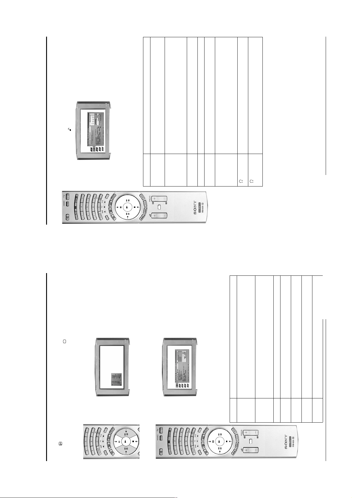
How to replace the fuse.
Open the fuse compartment with
a screwdriver blade and replace
the fuse.
FUSE
- 4 -
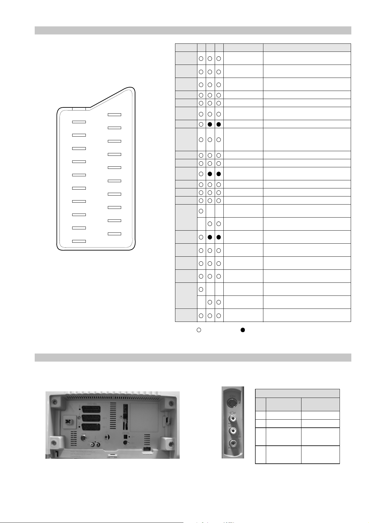
21 pin connector
21
19
17
15
13
11
9
7
5
3
1
20
18
16
14
12
10
8
6
4
2
Pin No 1 2 4 Signal Signal level
1 Audio output B
2
3
4 Ground (audio)
5 Ground (blue)
6 Audio input A
7 Blue input 0.7 +/- 3dB, 75 ohms positive
8 Function select
9 Ground (green)
10 Open
11 Green Green signal : 0.7 +/- 3dB, 75 ohms,
12 Open
13 Ground (red)
14 Ground (blanking)
15
16 Blanking input
17 Ground (video
18 Ground (video
19 Video output 1V +/- 3dB, 75ohms, positive sync 0.3V
20
21 Common ground
3
(right)
Audio input B
(right)
Audio output A
(left)
(left)
(AV control)
_ _ Red input 0.7 +/- 3dB, 75 ohms, positive
_ (S signal Chroma
input)
(Ys signal)
output)
input)
_ _ Video input 1V +/- 3dB, 75ohms, positive sync 0.3V
_ Video input
Y (S signal)
(plug, shield)
Standard level : 0.5V rms
Output impedence : Less than 1kohm*
Standard level : 0.5V rms
Output impedence : More than 10kohm*
Standard level : 0.5V rms
Output impedence : Less than 1kohm*
Standard level : 0.5V rms
Output impedence : More than 10kohm*
High state (9.5-12V) : Part mode
Low state (0-2V) : TV mode
Input impedence : More than 10K ohms
Input capacitance : Less than 2nF
positive
0.3 +/- 3dB, 75 ohms, positive
High state (1-3V) Low state (0-0.4V)
Input impedence : 75 ohms
(-3+10dB)
(-3+10dB)
1V +/- 3dB, 75ohms, positive sync 0.3V
(-3+10dB)
Connected Not Connected (open) * at 20Hz - 20kHz
Rear Connection Panel Front Connection Panel
S-Video
socket
niP
oN
1dnuorG2dnuorG3tupni)langisS(Y,mho57Bd3-/+V1
4tupni)langisS(CBd3-/+V3.0
langiS leveLlangiS
noitarugifnocniptekcosoediVS
V3.0.cnySevitisop
Bd01+3-
evitisop,mho57
.cnyS
- 5 -
AE-6D SELF DIAGNOSTIC SOFTWARE
The identification of errors within the AE-6D chassis is triggered in one of tw o ways :- 1: Busy or 2: De vice failure to respond to IIC. In the
event of one of these situations arising the software will first try to release the bus if busy (Failure to do so will report with a continuous
flashing LED) and then communicate with each device in turn to establish if a device is f aulty . If a device is found to be faulty the rele v ant
device number will be displayed through the LED (Series of flashes which must be counted) See table 1., non fatal errors are reported using this
method.
metIcitsongaiD
noitpircseD
nonruttonseodrewoPthgiltonseoD
)PCO(tnerrucrevOB+semit2
deppotsnoitcelfeDlacitreVsemit4
ybdnatSsemitfooN
sehsalFDEL
.tiucricneposiesuF
egasseMrorrE
rorreoN00
devreseR10
)noitcetorPtnerruCrevO(PCO20
)noitcetorPegatloVrevO(PVO30
noitcetorPlacitreV40
noitcetorPlatnoziroH60
noitcetorPrekaepS70
rorre0subC2I80
redoceD-txeT-eleTB-M90
MVN,23C42TSB-M01
redoceDruoloCniaM,0239ADTB-J11
dnekcaBQ0512AXCB-A21
rossecorPdnuoS,D0143PSMB-A31
orciMlatigiDAMMEB-N41
MARlanretxE81
esuacelbaborP
noitacoL
.nideggulptonsidrocrewoP
)draoBA(detrohssi1071CI
)sces03retfastratskcehc(BKAelbatsnU50
smotpmySdetceteD
noemoctonseodrewoP
VTehtotdeilppussirewopoN
ytluafsiylppusrewopCA
.)draoBD(detrohssi)4088/3088Q(TUO.H
.)draoBD(detrohssi)6088Q(TEFytiraeniL
)draoBD(nepo5388RdeilppustonsiV51+
)draoBD(nepo4388RdeilppustonsiV51-
DEL
edoC
noemoctonseodrewoP
detrohssahenilrewopnodaoL
deppotssaheslupnoitcelfedlacitreV
detrohssahenilrewoP
Flash Timing Example : e.g. error number 3
StBy LED
ON
OFF
ON ON
- 6 -
OFF

Error Detection Monitor
Device acknowledge is used to check IIC errors. De vice ackno wledge is checked by sending an IIC start sequence during CR T po wer on. Each
device is checked three times, if there is no acknowledge after each attempt, it will be re garded as an error.
There are three steps to check for errors.
1. IIC line 0
If all devices except the NVM have errors, IIC line 0 error is displayed.
2. Board check
If all devices mounted on one board have errors, board error is displayed.
3. Each device check
If IIC line error and board error are not detected then the device with the error is displayed.
The detected errors can be displayed as follows :
1. Error Monitor Menu.
2. Error Reader.
1. Error Monitor Menu
rotinoMrorrE
FFONOFFOSRORREERONGI.1
:srorrEderotS
derruccOrorrEoN.1
derruccOrorrEoN.2
derruccOrorrEoN.3
derruccOrorrEoN.4
derruccOrorrEoN.5
:rorrEtnerruC
ecneuqeSrorrEtratS
:uneMtsaL:metIretnE
nim54h922000:emiTgnitarepO
- 7 -
2. Error Reader Display
The error reader display is connected to the service connector to read actual error codes. The part number for the error reader display is
S-188-900-10. Once an error has been detected it will then be displayed on the two digit error reader. The errors displayed refer to the following
table.
rorrE
edoC
h000derruccororreoN
h1000CII,rorresuB
h2001CII,rorresuB
h001 draoB-A
h101rednapxEtroP,5781AXCB-A
h201renuTniaM,6231UTB-A
h401FIniaM,6889ADTB-A
h601dnekcaB,Q0512AXCB-A
h70114188BMB-A
h801CTR,3958FCPB-A
h004 draoBPB
h104XDIMroDIMB-PB
h304yarrAetaGamaronaPB-4B
h404CRDB-3B
h007 draoBJ
h307redoceDruoloCniaMB-J
h507dnuoS-buS,5781AXCB-J
h607rossecorPdnuoS,D0143PSMB-J
h807hctiwSVA,9X12AXCB-J
h008 draoBM
h108MVN,23C43TSB-M
h009 draoB-N
h109orciMlatigiDAMMEB-N
egasseMrorrE
- 8 -
SECTION 1 GENERAL
9
Using the text services
when viewing the text pages, press the OK button for ‘OK’ and ‘Select’, and the button for
‘Cancel’.
information.
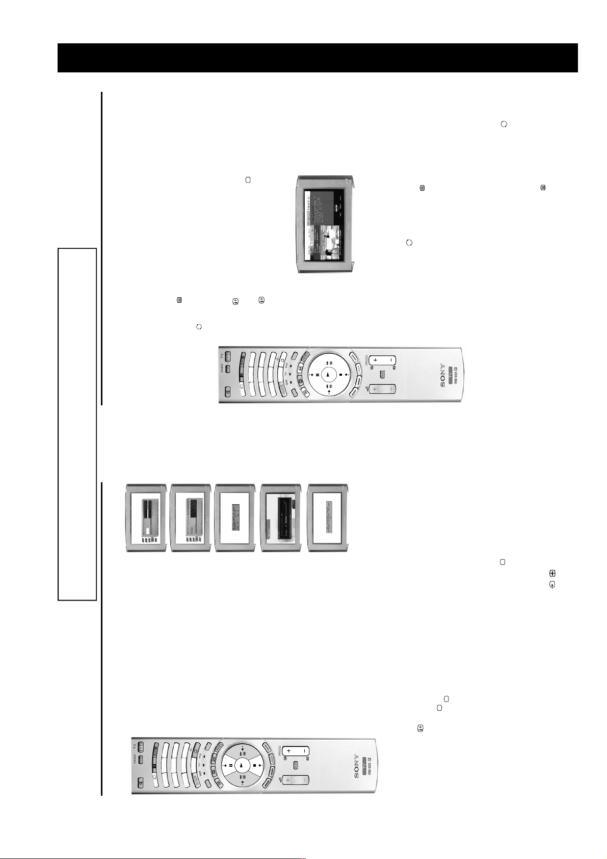
digital programme an Info display appears on screen providing brief details for the current and next
The OK button or the numbered buttons (to select items on screen),
The button (to cancel or exit),
Most digital TV channels broadcast information via their text service. This digital service includes high
quality text and graphics along with advanced navigation options. Additionally, this TV has access to
dedicated text channels transmitted by the broadcasting authorities.
The appearance, content and navigation methods of all Digital text services are decided by the
broadcaster. For example, the BBC’s Digital text service may look different to ITV’s Digital text. Most of the
Digital text services currently available use simple navigation methods based on the following buttons:
The four coloured buttons (to access shortcuts).
The text button to load up the Digital text,
The V, v, B and b buttons (to move around the screen),
programme. If the display does not appear, press the DIGITAL/ button to switch to digital mode.
Selecting a dedicated Digital text channel
1. Press the button on the remote control to check if you are in digital mode. If you are watching a
manual.)
number that is broadcasting the dedicated Digital text channel by using the numbered buttons on the
remote control. If you do not kn ow th e chan nel n umbe r of a ded icate d Dig ital text channel, you can use
the ‘Channel Index menu’ to find one. (Please refer to the ‘Channel index menu’ section of this
2. Press the button to remove the Info display from the TV screen then select the programme
3. Once the text page is displayed, follow the on-screen instructions to obtain your required selection.
button for ‘OK’ and ‘Select’, and the button for ‘Cancel’ or ‘Exit’.
Note: On some pages the TV programme may also be displayed on the text screen. On-screen instructions will
inform you how to change the displayed programme.
4. If you are instructed to press ‘OK’, ‘Select’ or ‘Cancel’ when viewing the text pages, press the OK
Selecting a text service from other Digital channels
Normal text services may also be available on other digital channels. This is sometimes indicated by a
5. When you have finished viewing the text service, press the button to exit.
small symbol on your TV screen, superimposed on the programme you are watching.
to display the various pages of text information. If you are instructed to press ‘OK’, ‘Select’ or ‘Cancel’
2. Alternatively, you may be instructed to use the numbered or coloured buttons on your remote control
1. Press the V, v, B, or b buttons to select the symbol, then press the OK button to display the chosen
buttons, the coloured buttons and/or the numbered buttons of the remote control.
3. Once the text information is displayed, you can access required information by using the V, v, B, or b
4. When you have finished viewing the text service, press the button to exit.
The operating instructions mentioned here are partial abstracts from the ‘Operating
Instruction Manual’. The page numbers of the ‘Operating Instruction Manual’ remain
as in the manual.
Using a Digital text service
DIGITAL
DIGITAL
3
6
258
1
4
REC
9
0
7
E
OD
M
OK
button repeatedly on
/
choose the country in which you wish to operate the TV, then press
the OK button to confirm.
The autotune prompt screen appears. Press the OK button to select
Yes and begin the digital autotune procedure.
As this may take some time, a menu appears on screen and informs
you of the tuning progress.
When all the available digital programmes are found, the analogue
tuning display appears and all the analogue signals are captured and
stored.
If no digital and no analogue signals are found, a display appears on
screen asking you to confirm your aerial is connected. Check your
aerial is connected then press the OK button to repeat the tuning
procedure.
menu appears on screen with the word ‘English’ highlighted. Press
require then press the OK button to confirm.
the V or v buttons on the remote control to choose the language you
1. When you switch on this TV for the first time, the Language/Country
Getting started
5. Automatically tuning the TV
DIGITAL
DIGITAL
Note: The digital features of this set are designed for use in Great Britain only.
3
258
1
2. The word Country is now highlighted. Press the V or v buttons to
6
4
REC
9
0
7
DE
MO
OK
Once all signals have been captured and stored, the TV returns to
normal operation and displays the digital programme captured on
programme number 1.
programme number 1 is displayed.
buttons on the remote control.
Note: If no digital signals are captured, then the analogue programme stored on
3. To view programmes, press the PROG+/- button or the numbered
button on the remote control. If you are watching a digital program me
Switching between digital and analogue
programmes
To check if you are watching a digital or analogue programme press the
an Info display appears on screen providing brief details for the current
and next programme. To change to analogue programmes press the
DIGITAL/ button. When you wish to return to digital programmes press
the DIGITAL/ button once more.
remote control.
If you connected a VCR to your TV when following the ‘Connecting your aerial
instructions’, you now need to find your video channel.
1. First ensure the TV is in analogue mode. If not press the DIGITAL/ button on the
6. Finding your video channel
‘Rearranging your channels’ section of this manual.
If you have connected your VCR using a scart lead, press the
recorded tape appears on screen.
2. Press the PROG+/- button on the remote control until the picture from the pre-
the remote control until the picture from the pre-recorded tape appears on the TV screen.
Notes: If you wish to move your video channel to a different programme number, refer to the
6
- 9 -
11
Using the text services
desired column, then press V or v button to select the rele vant ‘group’ or ‘block’ of
pages. Press the OK button to display the chosen pages.
a page. Once the page has been found, a blue symbol appears in the top left
corner of the screen. Press the button to view the page.
displayed at a set time. When selecte d, the ‘Time Page’ sub menu is displayed.
Enter the desired page number and the time you want the page to appear using
OK button to return page to normal siz e. Press B button to return to the text menu.
button to enlarge upper half of the page or v to enlarge the bottom half. Press the
Text Clear Use this feature to view the TV programme whilst the text service is searching for
Feature Function
4. Press the MENU button to remove the text menu from the screen.
Using the text menu
You can access more features by using the text menu:
1. Press the button on your remote control to enter the conventional text mode.
2. With the text display on screen, press the MENU button to display the ‘text’ menu.
The following table explains each feature and its function.
3. Press the V or v button to highlight your desired feature, then press the b button to select.
Top/Bottom/Full This feature allows you to enlarge sections of the displayed page. Press the V
Reveal Select this to reveal hidden information on the page (such as answers to a quiz).
the remote control buttons 0 - 9, then press OK button to confirm the settings.
Time Page This feature allows a time-coded text page (such as an alarm page), to be
pages and the second shows ‘groups’ of pages. Press b or B button to select t he
The TV then exits the text mode and the time is displayed in the top left corner of
the screen. At your requested time the text page is displayed.
TOP-Text pages are divided into two columns. The first column shows ‘blocks’ of
Page Overview
(Only for TOPText
broadcasts)
Using a conventional text service
DIGITAL
3
6
258
1
4
REC
9
0
7
E
D
O
M
OK
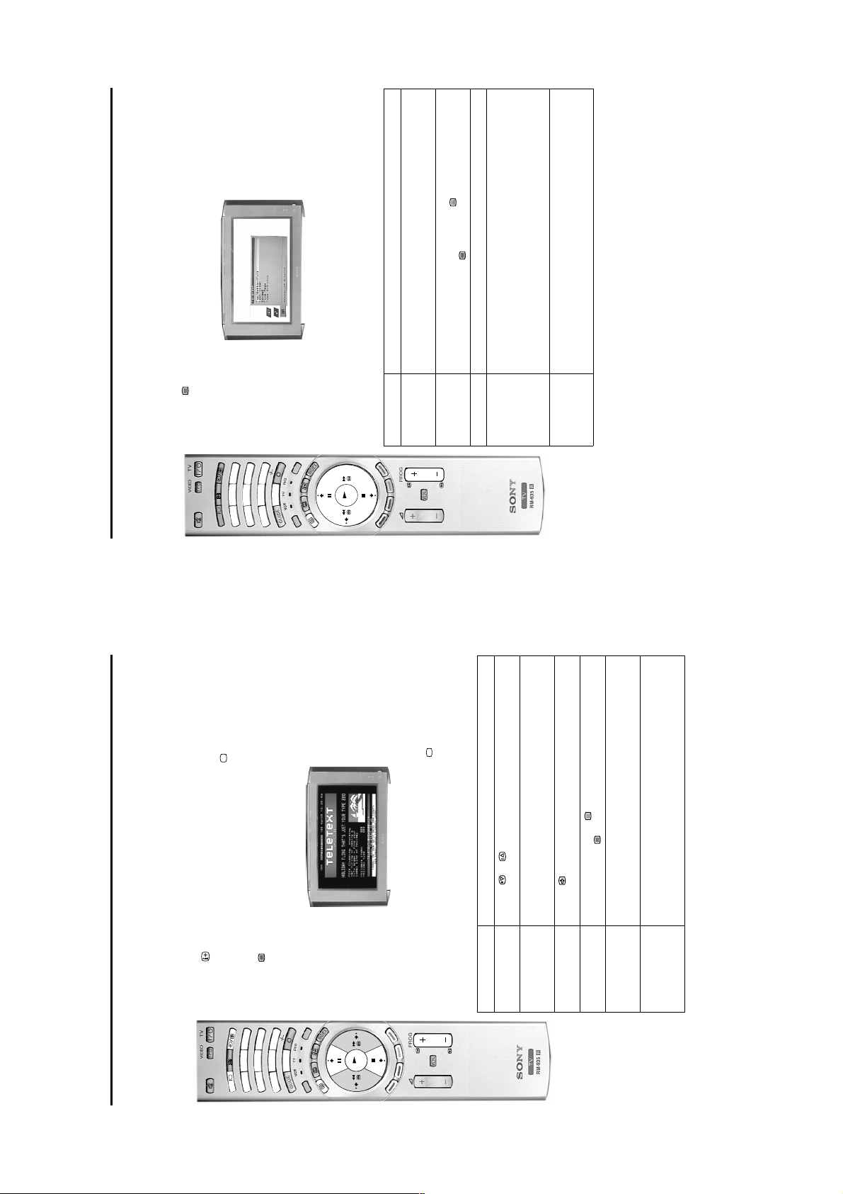
Using the text services
Using a conventional text service
Most analogue TV channels broadcast a text service. The index page (usually page 100) provides
information on how to use the service. Ple ase ens ure you are receiving a strong signal or some text errors
required, then press the OK button again. Your selected page appears on
Press the or button.
is displayed at the bottom of the screen showing the number of sub pages
available. Select the sub pages by pressing the V or v button.
Press the button. Press again to cancel.
the picture. Press the button again to return to TV mode.
available, four coloured items appear at the bottom of the screen. Press the
corresponding button on the remote control to display the page.
a digital programme an Info display appears on screen providing brief details for the current and next
programme. To change to analogue programmes press the DIGITAL/ button.
may occur.
Switching on the text service
1. Press the button on the remote control to check if you are in analogue mode. If you are watching
2. Select the TV programme which carries the text service you wish to view.
3
258
1
DIGITAL
DIGITAL
selected page appears on screen.
3. Press the button on the remote control to enter the text mode.
4. P ress the numbered buttons to enter a t hree digit numbe r for the text page you wish to view. Your
EC
6
4
R
9
0
7
MODE
OK
display from the screen.
5. Enter more 3 digit page numbers as required.
6. When you have finished viewing the text service, press the DIGITAL/ button to remove the text
Text Features How to select
To select the next or
preceding page
To select a sub page A text page can consist of several sub pages. In this case an information box
To keep a page on
display
To use mix mode When in text mode pre ss the button. The text page is superimpos ed onto
How to use the text features
To use Fastext Fastext allows you to access pages with one button push. When Fastext is
Select a page that contains several page numbers (e.g. the index page), then
To use the Page
screen.
press the OK button. Press the V or v button to highlight the page number
Catching feature
10
- 10 -
language is output to the headphone socket. Select A to listen to the first
language or B to listen to the second language.
the first language or B to listen to the second language.
When receiving Stereo broadcasts: Press V or v button to choose Mono or
band, then press V or v button to adjust the frequency level. Once the desired
adjustment is made press the OK button to store.
This option allows you to alter the sound by adjusting the 5 frequency bands
which control the overall sound effect. Press the B or b buttons to select each
When Dolby V. is selected, the TV simulates the full effects of Dolby Surround
sound when receiving a Dolby broadcast.
The table below explains the function of each option and which buttons to press for adjustment. Once
adjustment has been finalised, press the OK button to store.
1. Press the MENU button to display the main menu.
2. Press the v button to highlight the icon, then press the b button to highlight ’Sound Effect’.
3. Press the V or v button to select the option you wish to adjust, then press the b button to confirm.
REC
Option Adjustment/Effect
4. Press the MENU button when you wish to remove the menu from the screen.
Equaliser
Adjustment
Sound Effect Press V or v button to select from Personal, Dolby V*, Natural**, or Dynamic**.
(only available if
sound broadcast. (only when Dolby V has be en se le cted in Sound Effect option)
Virtual Effect Changes the level of surround sound effect when listening to a Dolby surround
Sound Effect is set
to ‘Personal’).
constant even if the broadcast level changes (during adverts for example).
Dual Sound When receiving bilingual broadcasts: Press V or v b utton to choos e A to li sten t o
Balance Press B or b button to set the balance to desired level.
Auto V ol. Control Press V or v button to set to On or Off. When set to On, the volume remains
socket and/or the audio out sockets on the rear of the TV.
Stereo.
Note: When NICAM is broadcast the word ‘NICAM’ appear s in the menu.
clarity, detail, presence of sound, and increases musical realism. The ‘BBE High definition Sound System’ is
manufactured by Sony Corporation under licence from BBE Sound, inc. It is covered by U.S. Patent No.
without the need for additional surround speakers. However, if you wish to connect an ext ernal amplifier to this
TV, please refer to the ‘Connecting external equipment’ section of this manual.
* When ‘Dolby V’ is selected, the TV simulates the full effects of Dolby Pro Logic Surround sound without the
Audio-out Vol. Press B or b button to increase or decrease the volume level to the headphone
Dual Sound When receiving bilingual broadcasts press V or v button to select which
need for additional speakers. Manufactured under licence from Dolby Laboratories. ‘Dolby’, ‘Pro Logic’ and
4,638,258 and No. 4,482,866. The word ‘BBE’ and the BBE symbol are trademarks of BBE Sound, Inc.
the double-D symbol are trademarks of Dolby Laboratories.
** Natural and Dynamic are functions of the ‘BBE High definition Sound System’. This sys tem enhances
Notes: This TV has been designed to create a Virtual Dolby Surround sound effect from a ‘Dolby Surround’ broadcast
TV menu system
TV menu system
Adjusting the sound
OK
L
ITA
ITAL
ITAL
IG
D
DIG
DIG
MODE
MENU
24
23
Warm, Normal or Cool.
Press V or v button to turn On or Off . Wh en set to On, the TV will monitor the picture
Game have had their picture levels preset to suit their intended functions, whilst
Personal mode allows you to set your own levels of brightness, sharpness and
colour.
Press B or b button to increase o r d ecr eas e the levels to suit personal taste. You can
only adjust the Colour, Brightness and Sharpness if you have selected ‘Personal’ in
‘Picture Mode’ option.
1. Press the OK button to display the programme list on screen.
REC
DE
O
The following pages explain the TV set up menus and their operation. Although most of these menus can be accessed whilst
watching digital programmes, we recommend you switch to analogue mode to view all the menus. To check which mode you are in,
press the button on the remote control. If you are watchi ng a di gi tal programme, an Info displa y a ppe ars on screen providing brief
details for the current and next programme. If this happens, press the DIGITAL/ button on the remote control to switch to the
traditional analogue channels.
Using the programme index table
M
2. Press the V or v button to scroll through the list until the programme number you wish to view is
OK
1. Press the MENU button to display the main menu, then press the b button to highlight ‘Picture Mode’.
L
L
L
A
A
A
IT
IT
IT
IG
IG
IG
D
D
D
Adjusting the picture
The programme index table is an easy way to search for a programme you wish to view.
highlighted, then press the OK button to display that programme on screen.
The table below explains the function of each option and which buttons to press for adjustment. Once
adjustment has been finalised, press the OK button to store.
2. Press the V or v button to highlight the option you require then press the b button to confirm.
REC
DE
O
M
Option Adjustment/Effect
3. Press the MENU button when you wish to remove the menu from the screen.
OK
Picture Mode Press V or v button to select Live, Personal, Movie or Game mode. Live, Movie and
MENU
Contrast
Brightness
Colour
and limit any sudden increases in brightness and contrast.
Reset Resets picture to factory preset levels.
AI (artificial
intelligence)
Sharpness
quality, ‘DRC50’ for improved resolution or ‘DRC100’ for optimum picture resolution.
Press V or v button to switch On or Off. When set to On, this option can sometimes
reduce the noise level apparent on a weak signal.
Press V or v button to set the desired picture resolution. Set to ‘Off’ for basic picture
Noise
Colour Tone Press V or v button to alter the tint of the colour to suit your taste. Choose from
Detection
DRC
Mode
- 11 -
TV menu system
search.
If you have selected EXT:
Press the V or v button to select the AV socket whose input you wish to view on the programme
menu.
Manual Programme Preset menu.
With this feature you can manually add analogue programmes to your TV. Manual tuning also allows you
to select inputs from the scart sock ets (VCRs e tc) so t hat the y can be vie w ed on the pro gra mme n um ber of
your choice.
To check which mode you are in, press the button on the remote control. If you are watching a digital
programme, an Info display appears on screen providing brief details for the current and next programme.
If this happens, press the DIGITAL/ button on the remote control to switch to the traditional analogue
channels.
1. Press the MENU button to display the main menu.
2. Press the v button to highlight the icon, then press the b button to highlight ‘Auto Tuning’.
L
L
AL
A
AL
A
IT
IT
IT
IT
IG
IG
IG
IG
D
D
D
D
3. Press the v button to highlight ‘Manual Se t Up’ then press the b button to di splay the Manual S et Up
3
3
6
6
258
258
1
1
4
4
4. Press the v button to highlight ‘Manual Programme Preset’ then press the b button to display the
EC
R
9
9
0
0
7
7
ODE
M
OK
highlight the SKIP column.
5. Press the V or v button to highlight the programme number you require, then press the b button to
MENU
sockets (AV1, AV2 etc.). Press b butto n to confi rm your ch oic e .
7. Press the V or v button to select your system requirement. For example, choose I for theTV broadcasts
6. Press the V or v button to set to OFF, then press the b button to highlight SYS column.
broadcast. If the broadcast found is not the one you desire, press the V or v button to repeat the
frequency input, then press b button to confirm your choice.
If you know the channel number or frequency number you require, use buttons 0 - 9 on the remote
control to enter the number, otherwise press the V or v button to search for the next available
If you selected a TV broadcast system:
Press the V or v button to select ‘C’ for terrestrial channels, ‘S’ for cable channels or ‘F’ for direct
or ‘EXT’ if you wish to view signals from your VCR or other equipment you have connected to the scart
number chosen in step 5.
Manually tuning analogue signals
MENU button to remove the menu from the screen .
8. Press the OK button to store.
9. Repeat steps 5 - 8 if you wish to tune in broadcasts to other programme numbers, then press the
30
TV menu system
Due to the Earth’s magnetic field the picture can sometimes slant. This feature enables you to cancel out
Adjusting the picture rotation
button to select.
menu.
5. Press the V or v button to rotate the picture over a range of -5 to +5 then press the OK button to store.
any such effect.
1. Press the MENU button to display the main menu.
2. Press the v button to highlight the icon, then press the b button to highlight ‘Auto Tuning’.
3. Press the v button to highlight ‘Manual Set Up’ then press the b button to display the Manual Set Up
4. Press the v button to highlight ‘Picture Rotation’ then press the b button to select.
REC
OK
MODE
6. Press the MENU button to remove the menu from the screen.
MENU
Setting your personal ID
This feature allows you to enter a safety code to the TV, which would help you to be traced if the TV is
stolen and recovered. This code can only be entered once, so please make a note of it and keep it safe.
1. Press the MENU button to display the main menu.
menu.
3. Press the v button to highlight ‘Manual Set Up’, then press the b button to display the Manua l Se t Up
2. Press the v button to highlight the icon, then press the b button to highlight ‘Auto Tuning’.
DIGITAL
4. Press the v button to highlight ‘Personal ID’ then press the b button to select.
C
E
R
OK
E
D
O
M
your confirmation. Press OK to confirm and save.
6. Repeat the procedure to complete your ID code, then press the OK button. A box appears requesting
5. Press the V or v button to display the first character you require (letter or number), then press the b
MENU
7. Press the MENU button to remove the menu from the screen.
28
- 12 -
Additional information
/
35
remote control.
colour levels.
analogue signals’ instruction in this manual, then contact a local installer to
find out when digital transmissions begin in your area.
your aerial at.
• Power off.
(Contact a local installer)
• TV in standby.
• Ae r ial di sc onnected.
• Pictur e preset level adjustment.
• No d ig ital t rans m is sions in your area.
• No digital transmissions from the transmitter you are currently using.
• Weak signa l .
• Unsuitable aerial.
• Scram bled/su bscription-only channel.
• Programm e used only for data (no picture or sound).
• Programme not being transmitt ed.
• Digi t al mode Timer Record active (regular flash).
• Fault (irregular flas h) .
• Volume control.
• Wro ng external mode selected on an RGB video source.
• Colour level setting.
• Batteries low.
• Inpu ts from external equipment not switched off.
• Plug in the TV.
• Pres s th e button on the front of the TV.
• If the indi ca to r is on press the button or a numbered button on the
• Che ck the ae rial connection.
• Select ‘Picture Adjustment’ menu then adjust the brightness, picture and
• Tune in the analogue channels available us i ng the ‘Manually tuning
• Contact a local installer to find out which transmitter you should be pointing
• Cha nge your aerial to cover the channels used by digital programmes.
• Ensure aerial is correctly aligned to transmitter.
• Ensure aerial is plugged directly into the TV (not through other equipment).
• Upgrad e to a hi gher gain aerial.
• Su bsc r i be to pay-per-view broadcaster.
• See ‘Skipping a programme’ section.
• See ‘Re-arranging your channels’ section.
control.
screen.
• Do n ot open the cabinet, refer to qualified personnel.
• Con t act your ne are st Sony Service Centre.
• Press the + button on the remote control.
• If is displayed on the screen, press the button on the remote
colour setting.
• Press the button repeatedly until the RGB sym bo l is displayed on
• Select ‘Picture Adjustment’ menu on the TV menu system the n adjust the
Troubleshooting
Additional information
Here are some simple solutions to problems which may affect the picture and sound.
Problem Cause
No picture, no sound.
Poor or no picture (screen is dark), but goo d
sound.
No picture on any channel after digital t uning.
Some channels are blank.
Standby indicator flashing.
Good picture, no sound.
Poor picture quality.
No colour on colour programmes.
Remote control does not function.
Distorted picture when changing progr ammes or
selecting Teletext.
Cause Solution
Power off.
TV in standby.
Aerial disconnected.
Picture level adjustment.
No digital transmissions in your area .
No digital transmissions from the transmitter you
are currently usin g.
Unsuitable aerial.
Weak signal.
Scrambled/subscription-only channel.
Programme information without picture or sound.
Fault.
Volume control.
Wrong external mode selected.
the Sony UK Digital HelpLine on 0870 600 1717.
Colour level setting.
• If you continue to have these problems, have your TV serviced by qualified personnel or you can contact
• NEVER open the casing yourself.
33
LOEWE 009, 028, 023, 024, 016. 003
SAMSUNG 11, 14
Remote control configuration for VCR/DVD
354, 348, 349
to it, make a note of the first code only at this stage.
illuminated.
approximately 6 seconds, until the light starts to flash.
lights will illuminate momentarily.
steps 2 - 4 and enter the next 3 digit code allocated to your brand of VCR or DVD.
green light illuminates. Don’t forget to select VCR or DVD using the MODE button every time you wish
This remote control has been config ured to oper ate no t on ly Son y DVDs and VCRs but also those made by
to operate that equipment with this remote control.
other manufacturers. To operate other makes of DVD and VCR using this remote control, complete the
following procedure:
1. Find the 3 digit code for your brand from the list below. If your brand has more than one code allocated
2. Press the MODE butto n on the remote control until either the VCR green light or the DVD green light is
3. Whilst the required green light is illuminated, press and hold down the YELLOW button for
4. Enter the 3 digit code for your DVD or VCR. Once a correct number has been entered, all three green
5. Tu rn on you r DVD or VCR and check that the remote control operates the ma in fun cti on s . If no t, repe at
6. When you wish to use the remote control to operate the TV again, press the MODE button until the TV
Note: The brand codes you set may be lost if weak batteries are not replaced immediately. Should this
happen, use the above procedure to reset the code. A small label has been attached to the inside of the
battery cover for you to make a note of your brand codes.
REC
9
9
0
7
7
MODE
L
L
L
A
A
A
IT
IT
IT
IG
IG
IG
D
D
D
3
3
6
6
258
2
580
1
1
4
4
Not all brands and models of DVDs or VCRs are covered in this list. However, Sony will endeavour to
VCR Brand List DVD Brand List
Brand Code Brand Code
SONY (VHS) 301, 302, 303, 309 SONY 001
SONY (BETA) 301, 302, 303, 309 AIWA 021
SONY (DVD) 304, 305, 306 DENON 018, 027, 020, 002
AIWA 325, 331, 351 GRUNDIG 009, 028, 023, 024, 016. 003
AKAI 326, 329, 330 HITACHI 025, 026, 015, 004
DAEWOO 342, 343 JVC 006, 017
GRUNDIG 358, 355, 360, 361, 320, 351 KENWOOD 008
HITACHI 327, 333, 334 LG 015, 014
JVC 314, 315, 322, 344, 352, 353,
LG 332, 338 MATSUI 013, 016
LOEWE 358, 355, 360, 361, 320, 351 ONKYO 022
update the software periodically, so please refer to the code table provided with your remote control.
MATSUI 356, 357 PANASONIC 018, 027, 020, 002
358, 359
ORION 328 PHILIPS 009, 028, 023, 024, 016. 003
PANASONIC 321, 323 PIONEER 00 4
PHILIPS 311, 312, 313, 316, 317, 318,
SAMSUNG 339, 340, 341, 345 SANYO 007
SANYO 335, 336 SHARP 019, 027
SHARP 324 THOMSON 012
THOMSON 319, 350 TOSHIBA 003
TOSHIBA 337 YAMAHA 018, 027, 020, 002
- 13 -
SECTION 2 DISASSEMBLY
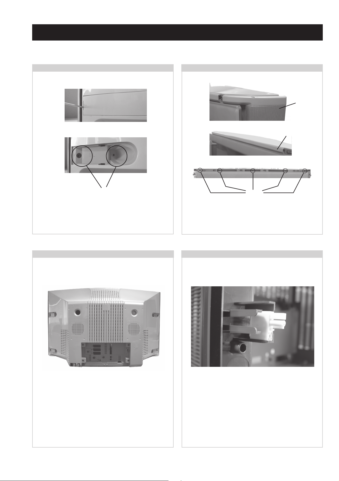
2-1. Rear Cover Removal (Step 1)
Screws
Using a narrow blade screwdriver lever off the 4 screw
covers from the rear of the set. Remove the 12 speaker grill
and rear cover fixing screws. (See 2-3.)
2-2. Rear Cover Removal (Step 2)
Speaker
Grill
Ornamental
Plate
Screws
Remove the speaker grills by holding top and bottom and
sliding away from the set. Remove the ornamental plate
from the top front of the beznet by sliding to the right.
Remove the 5 screws indicated from the top front of the set.
2-3. Rear Cover Removal (Step 3) 2-4. Speaker Connector Disconnection
=>
=>
Remove the rear cover by sliding backwards away from the
picture tube. Take care when removing the rear cover not to
damage the speaker cables [Disconnect the speaker
connector] as speakers are fitted inside the rear cover.
=>
=>
=>
=>
=>
=>
=>
=>
=>
=>
Before completely removing the rear cover disconnect the
speaker connector which is located on the inside of the rear
cover.
- 14 -
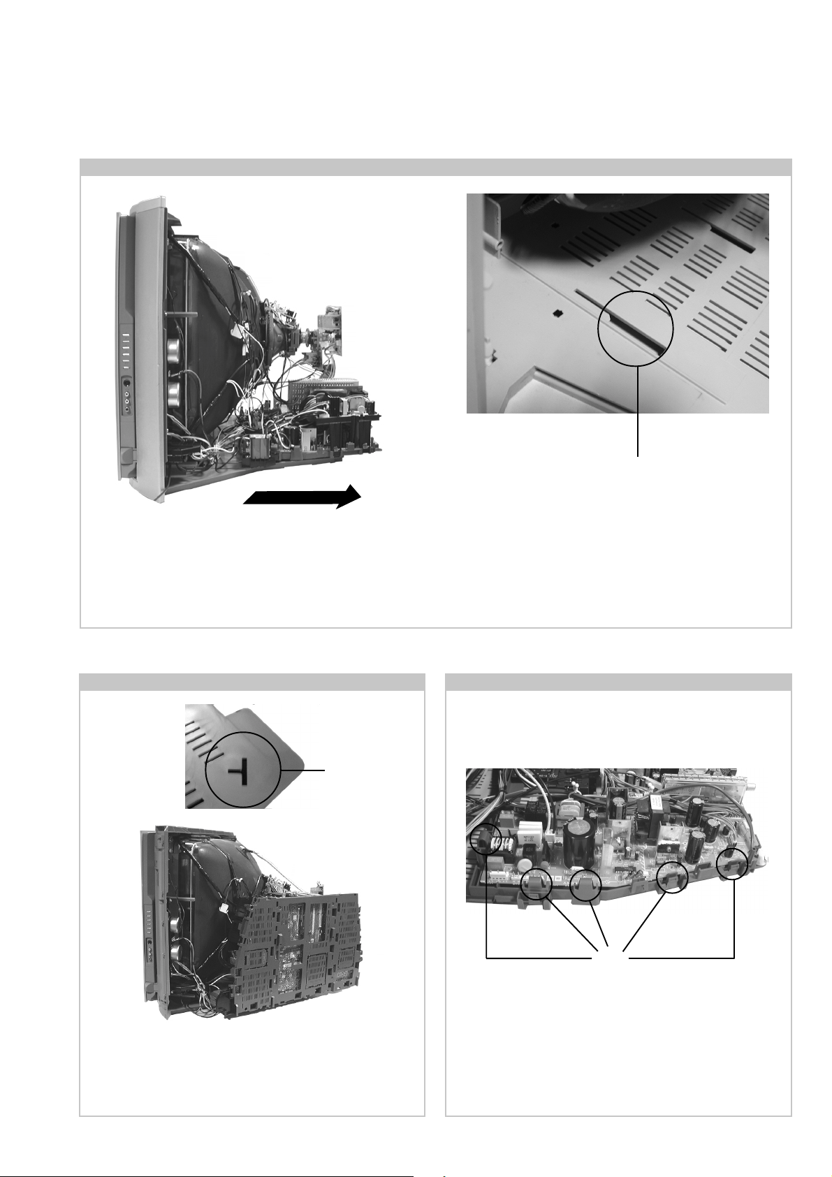
2-5. Chassis Removal and Refitting
T o remove lift the main bracket rear slightly and slide the
chassis away from the beznet. Ensure that the interconnecting
leads are released from their purse locks to prevent damage
being caused.
When refitting the chassis ensure that the main bracket is
located in the beznet guide slots before sliding the chassis
forwards. Refit the interconnecting leads in their respective
purse locks.
2-6. Service Position
Slot
Using the slot on the rear left of the beznet position the
chassis as indicated to access the solder side. T o gain access
to the underside of the boards follow the instructions on
page 18. [Removal and Replacement of the main bracket
bottom plates ].
2-7. D and G Board Removal
Clips
T o remove the G Board release the clips circled and ease the
board gently away from the support bracket. Removal of the
D Board follows the same procedure.
- 15 -
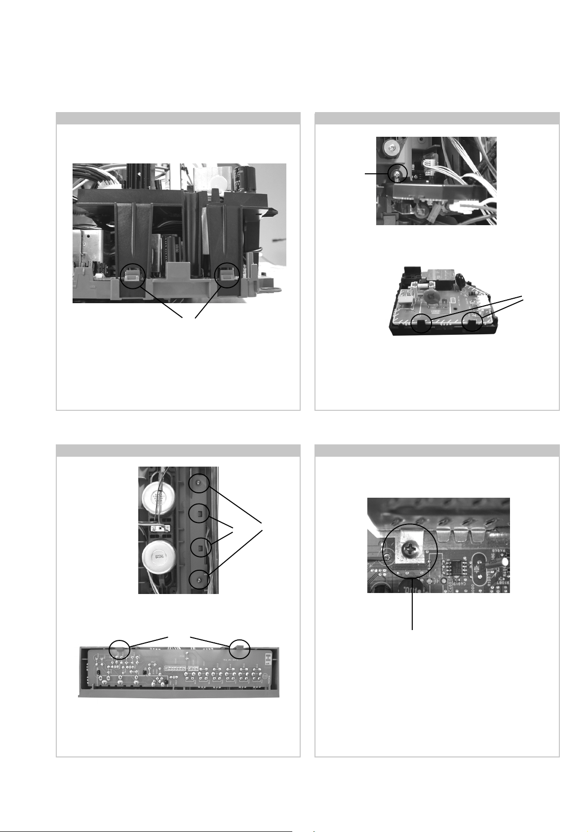
2-8. G1 Bracket Removal
Clips
T o remove the G1 Brack et release the four clips (two on each
side of the bracket) and carefully lift away from the chassis.
2-9. F1 Board Removal
Screw
Remove the F1 bracket by removing the screw indicated and
sliding the bracket away from the beznet.
Clips
T o remove the F1 board release the tw o clips circled and ease
the board gently away from the support bracket.
2-10. H1 Board Removal 2-11. Removal of N Board Shield
Screws
Clips
Remove the H1 bracket by removing the screws indicated.
Release the two clips circled and ease the bracket out of its slot
in the beznet.
Clips
Screw
T o remov e the N Board shield, release the two f ixing scre ws
and lift the shield vertically until it is clear of the chassis.
T o remove the H1 board release the two clips circled and ease
the board gently away from the support bracket.
Note : Removal of the H3 Board follows the same procedure.
- 16 -
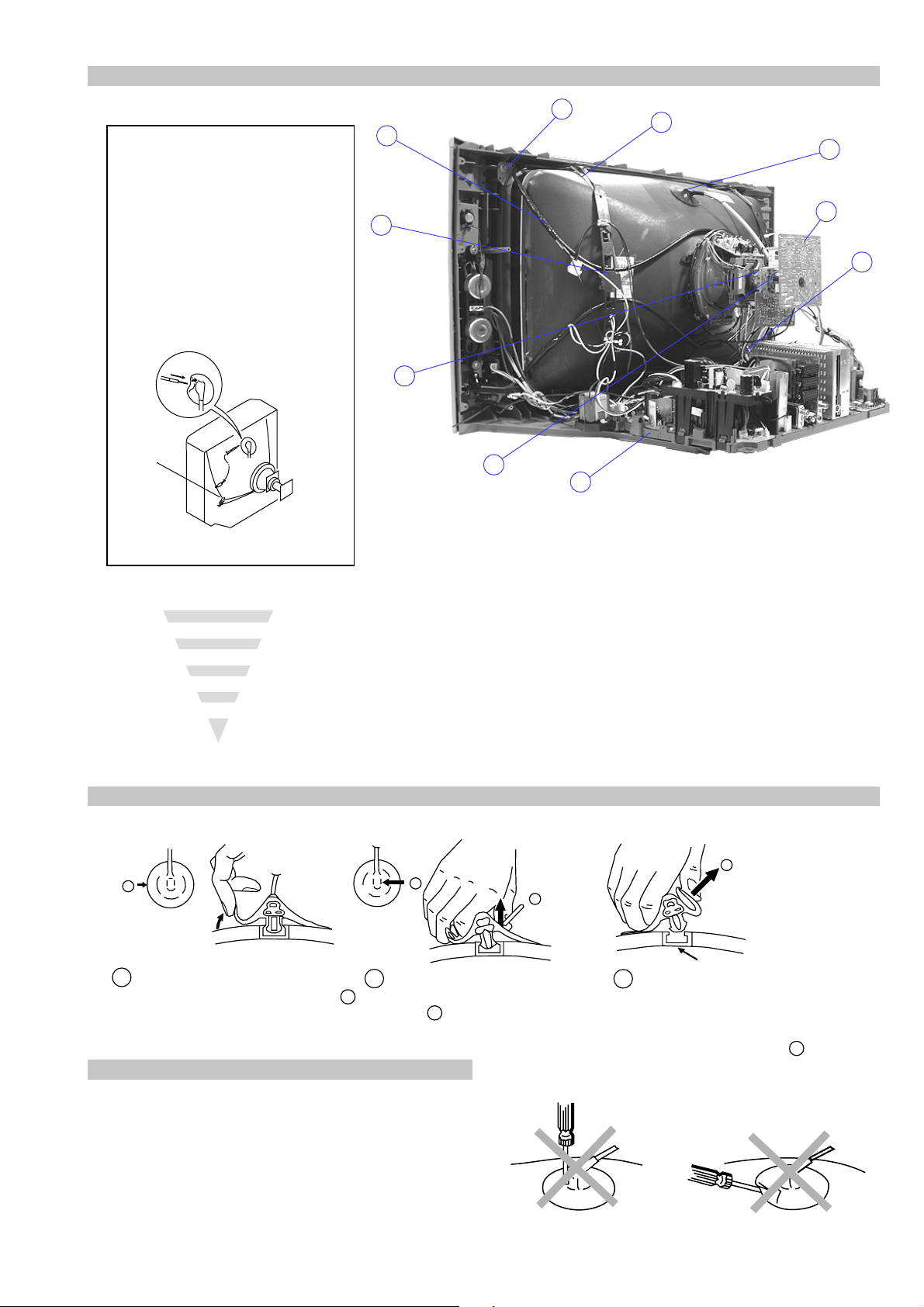
2-12. Picture Tube Removal
WARNING:
BEFORE REMOVING
THE ANODE CAP
High voltage remains in the CRT even
after the power is disconnected. To
avoid electric shock, discharge CRT
before attempting to remove the anode
cap. Short between anode and CRT
coated earth ground strap.
Coated Earth
Ground Strap
10
9
8
1
3
7
2
6
5
4
1. Discharge the anode of the CRT and remove the anode cap.
2. Unplug all interconnecting leads from the Deflection yoke, neck
assy, de gaussing coils and CRT grounding strap.
3. Remove the C Board from the CRT .
4. Remove the chassis assembly.
5. Loosen the Neck assembly fixing screw and remove.
6. Loosen the Deflection yoke fixing screw and remove.
7. Place the set with the CRT face down on a cushion and remov e
the Degaussing Coil holders.
8. Remove the Degaussing Coils.
9. Remove the CRT grounding strap and spring tentioners.
10. Unscrew the four CRT fixing screws [ located on each CRT
corner ] and remove the CR T .
[T ake care not to handle the CR T by the neck.]
Removal of the Anode-Cap
* REMOVING PROCEDURES.
a
1
Turn up one side of the rubber cap in
the direction indicated by the arrow a
b
2 Using a thumb pull up the rubber cap
firmly in the direction indicated by the
arrow b
How to handle the Anode-Cap
1. To prevent damaging the surface of the anode-cap do not use
sharp materials.
2. Do not apply too great a pressure on the rubber, as this may cause
damage to the anode connector.
3. A metal fitting called a shatter hook terminal is fitted inside the
rubber cap.
4. Do not turn the rubber foot over excessively, this may cause
damage if the shatter hook sticks out.
c
b
Anode button
3 When one side of the rubber cap is
separated from the anode button, the
anode-cap can be removed by turning
up the rubber cap and pulling it up in
the direction of the arrow c
- 17 -
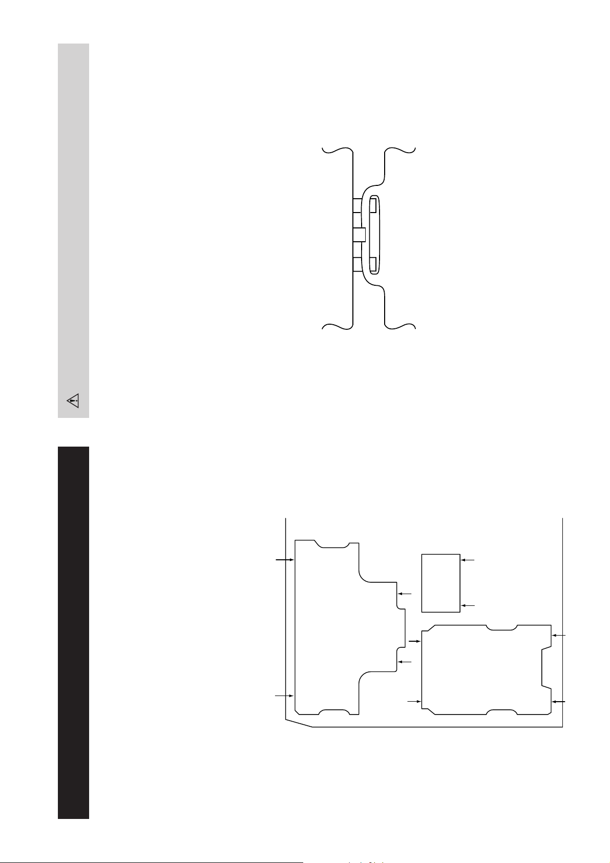
Catch
For safety reasons, on no account should the plates be removed
and not refitted after servicing.
Because the plates differ in size it is important that the correct plates are refitted in their original
location.
Please note that the plates need to be rotated 180 degrees from their cut position to allow the
(2) REFITTING THE PLATES
tabs to be fitted into their catch positions.
Ta b
REMOVAL AND REPLACEMENT OF THE MAIN-BRACKET
BOTTOM PLATES.
Only remove the necessary plate to gain access to the printed wiring board.
In the event of servicing being required to the solder side of some of the printed wiring boards,
the bottom plates fitted to the main chassis bracket require to be removed.
This is performed by cutting the gates with a sharp wire cutter at the locations indicated by the
arrows.
(1) REMOVING THE PLATES
Note : There are 3 plates fitted to the main bracket and secured by3 gates.
- 18 -
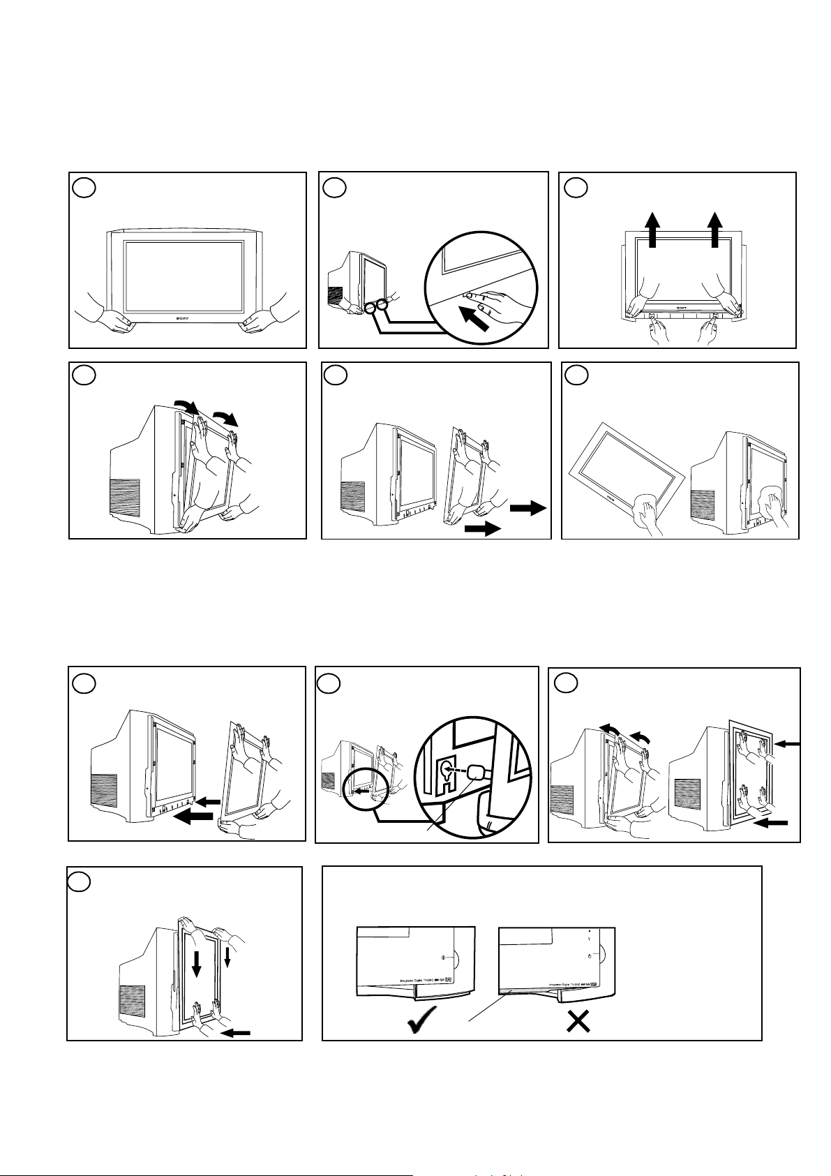
From time to time dust particles or condensation may get trapped between the glass panel and the TV screen. These instructions will
guide you through the steps required to both remove and re-fit the glass panel safely.
Removing the glass panel
NEVER attempt to remove the glass panel on your own - for safety reasons Sony recommends that two people carry out the
following procedure at all times.
Support the bottom of the glass
1
panel as shown AT ALL TIMES.
Trinitron
Supporting the glass panel, tilt it
away from the TV.
Push the clips located on the
2 3
underside o f the TV , as shown , to
release the glass panel.
Carefully remove the glass panel
and place it safely in an upright
position. To avoid inju ry or damage,
do not leave it on the floor.
Whilst pushing the release clip,
slide the glass panel up.
Clean both sides of the glas s and the
654
TV screen. Use a soft, damp, lin t free
cloth. Do not use any chemical
solutions or abrasive cleaners.
Re-fitting the glass panel
NEVER attempt to re-fit the glass panel on your own - for safety reasons Sony recommends that two people carry out the following
procedure at all times.
Lift the glass, and move toward
1
the TV.
While still maintaining forward
4
pressure to the bottom of the glass,
carefully slide the glass down until it
locks.
Insert the bot tom locating pins of
2
the glass panel into the keyhole
slots on the TV.
Locating pin
CAUTION
Before removing your hands check that you are unable to move the glass.
When correctly fi tted, th e pla stic rib sh own in the draw ing b elow s hould not b e
visible.
Tilt the glass panel forwards at the
3
top to engage all the locating pins,
then push forward firmly to secure.
Plastic rib
Safety No te
The glass panel suppl ied complies with all relevan t safety regul ations. How ever, should the glass becom e damaged at
any time, it is strongly recommended that a replacement is obtained from an authorised Sony dealer.
- 19 -
SECTION 3 SET -UP ADJUSTMENTS
• When complete readjustment is necessary or a new picture
tube is installed, carry out the following adjustments.
• Unless there are specif ic instructions to the contrary , carry
out these adjustments with the rated power supply .
• Unless there are specif ic instructions to the contrary , set the
controls and switches to the following settings :
Contrast .................... 80% [or remote control normal]
Brightness................... 50%
Preparation:
1. In order to reduce the influence of geomagnetism on the
set’s picture tube, face it in an easterly or westerly direction.
2. Switch on the set’s power and degauss with the degausser .
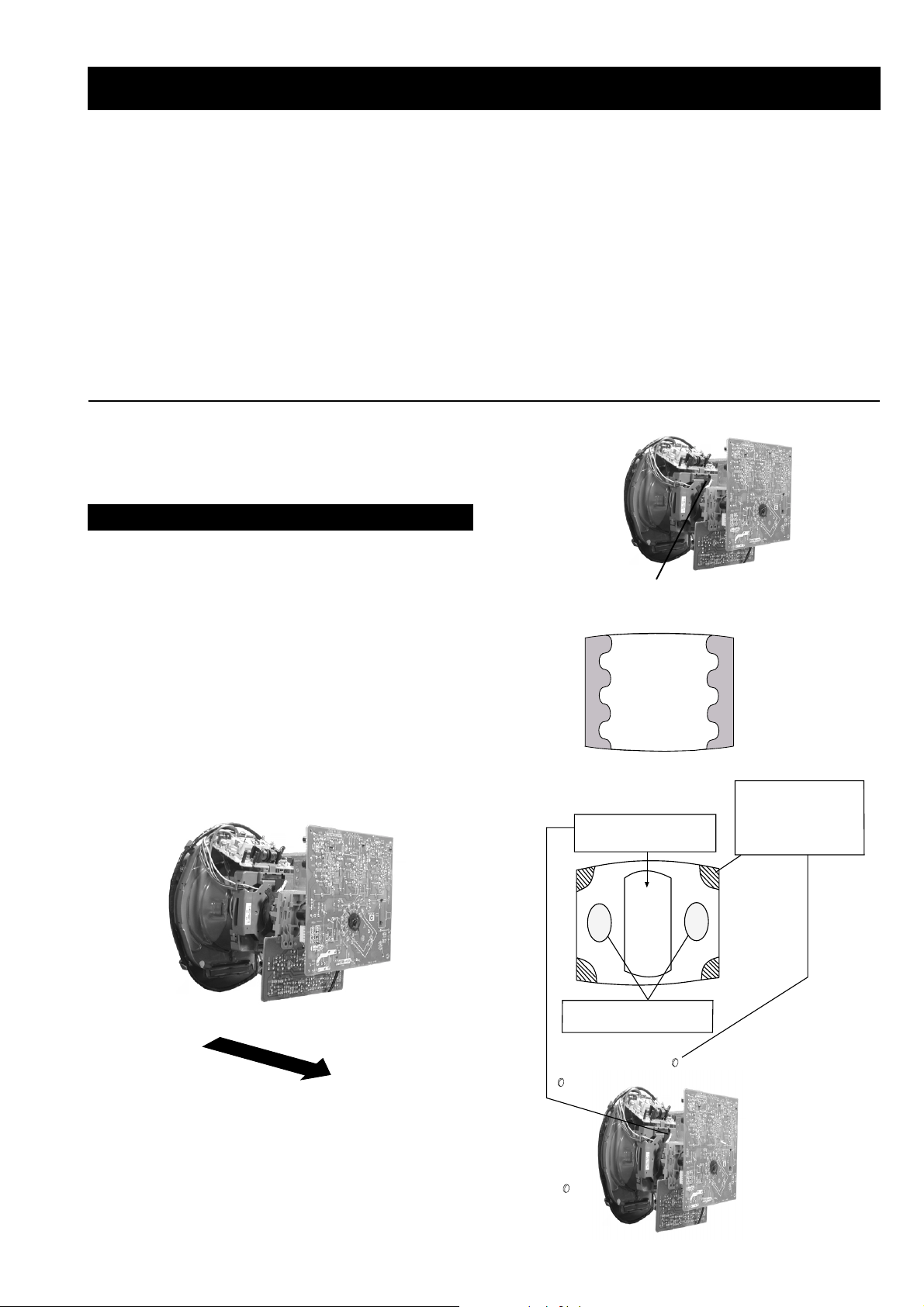
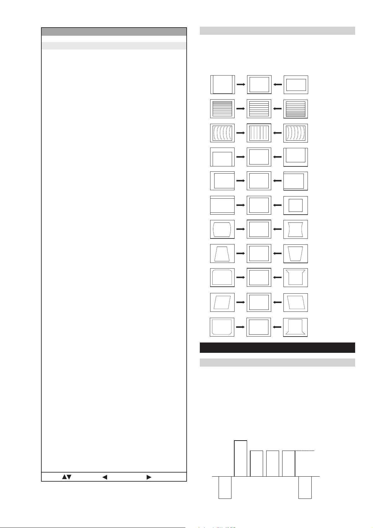
3-1. Beam Landing
1. Input an all white signal from the pattern generator. Set the
Contrast and Brightness to normal.
2. Set the pattern generator raster signal to Red.
3. Move the deflection yoke forward and adjust with the
purity control so that the Red is at the centre and the Blue
and Green take up equally sized areas on each side of the
screen. [See Fig.3-1 - 3-3].
4. Move the deflection yoke backwards and adjust so that the
entire screen becomes Red. [See Fig.3-1]
5. Switch the raster signal to Blue, then to Green and verify
the condition.
6. When the position of the deflection yoke has been
determined, fasten the deflection yoke with the screws.
7. If the beam does not land correctly in all the corners, use a
magnet to correct it. [See Fig.3-4]
Carry out the adjustments in the following order :
3-1. Beam Landing.
3-2. Convergence.
3-3. Focus.
3-4. White Balance.
Note : T est equipment required.
1. Color bar/pattern generator .
2. Degausser.
3. Oscilloscope.
4. Digital multimeter.
Fig. 3-2.
Purity
Fig. 3-3.
GREEN
RED
BLUE
Disk magnets or
rotatable disk
Purity control corrects
this area
magnets correct
these areas (a-d)
Fig. 3-1.
Caution :
High voltages are present on the Deflection yoke terminals
- take care when handling the Deflection yoke whilst carrying
out adjustments.
- 20 -
Disk Magnets
Fig.3-4
a
cd
Deflection yoke positioning
corrects these areas
b
GBR
GBR
GBR
G
B
R
GBR
G
B
R
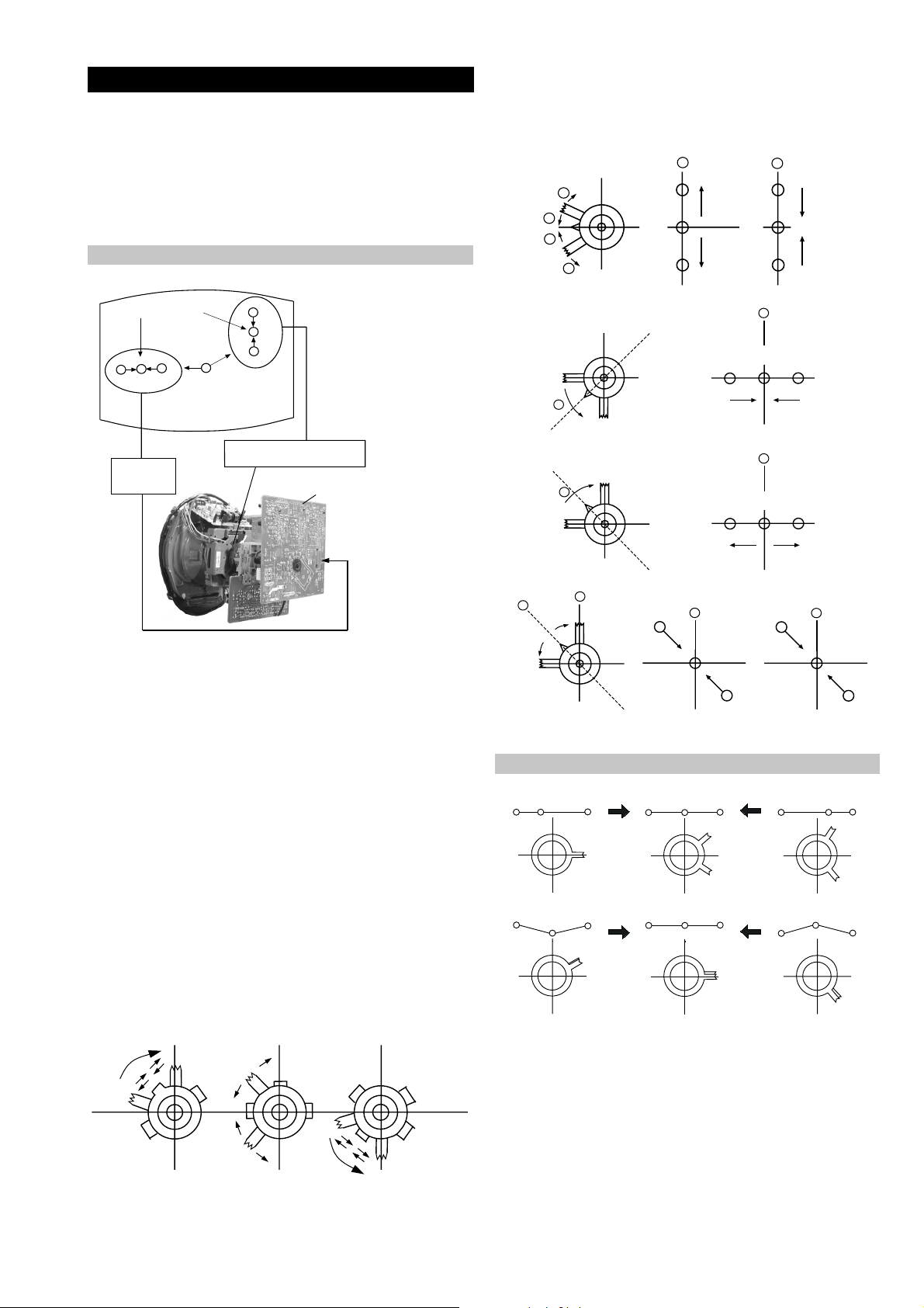
3-2. Con vergence
B
G
R
a
b
R
G
B
b
a
Preparation:
4. If the V.STAT magnet is moved in the direction of the (a)
and (b) arrows, the Red, Green and Blue points move as
indicated below .
• Before starting this adjustment, adjust the focus, horizontal
size and vertical size.
• Minimize the Brightness setting.
• Input a dot pattern from the pattern generator .
Horizontal and Vertical Static Convergence
Center dot
R
G
B
H STAT
convergence
control
R
G
B
V.STAT Vertical Static Magnet
C Board
RV5375 (H STAT)
H STAT Convergence
(on mount side)
a
b
a
a
b
B
G
R
R
a
b
R
b
B
G
R
a
B
G
b
B
G
Fig.3-5
1. [Moving horizontally], adjust the H.ST AT control so that
the Red, Green and Blue points are on top of each other at
the centre of the screen.
Operation of the BMC (Hexapole) magnet.
2. [Moving vertically], adjust the V.STAT magnet so that the
Red, Green and Blue points are on top of each other at the
centre of the screen.
3. If the H.STAT variable resistor is unable to bring the Red,
Green and Blue points together at the centre of the screen,
adjust the horizontal convergence with the H.STA T variable
resistor and the V.STAT magnet in the manner indicated
below.
[In this case, the H.ST AT variable resistor and the V.ST AT
magnet influence each other].
• Tilt the V.STAT magnet and adjust the static convergence by
opening or closing the V.STAT magnet.
The movement of the magnets interact with each other and so
the respective dot position should be monitored while carrying
out this adjustment.
Use the H.STA T VR to adjust the Red, Green and Blue dots so
that they coincide at the centre of the screen
(by moving the dots in the horizontal direction).
- 21 -
+
YCH VR
Deflection Yoke
+
+
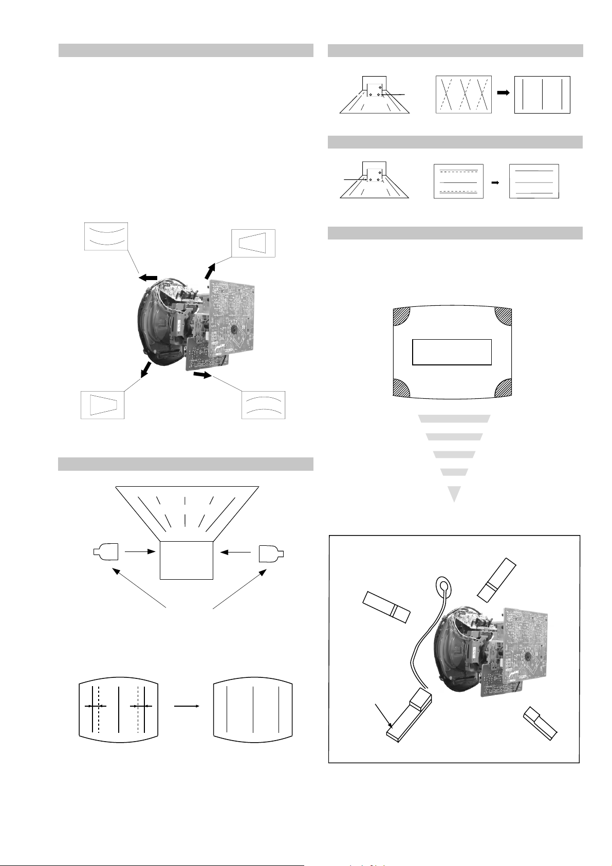
Geometry Adjustment.
Preparation:
Before starting this adjustment, adjust the horizontal and
vertical static convergence.
1. Remove the deflection yoke spacer.
2. Tilt the deflection yoke as indicated in the figure below and
optimise the geometry.
Tilting the D Y Up and Down will balance the upper and
lower pin adjustment.
Tilting the D Y Left and Right will balance the H-Trap
adjustment.
3. Re-install the deflection yoke spacer.
YCH Adjustment
TL V Adjustment
+
+
TLV VR
+
Deflection Yoke
Screen Corner Convergence
If you are unable to adjust the corner conver gence properly ,
this can be corrected with the use of permalloy magnets.
HTIL Adjustment
Deflection Yoke
TLH pieces
a
a-d: screen-corner
convergence defect
c
Install the permalloy assembly
for the area that needs correcting.
b
b
d
a
HTIL correction can be performed by adding a TLH correction
assembly to the Deflection yoke.
- 22 -
Permalloy Assy
X-4387-214-1
d
Convergence adjustment with permalloy
c
Layout of each control
V.STAT
Purity
BMC (Hexapole)
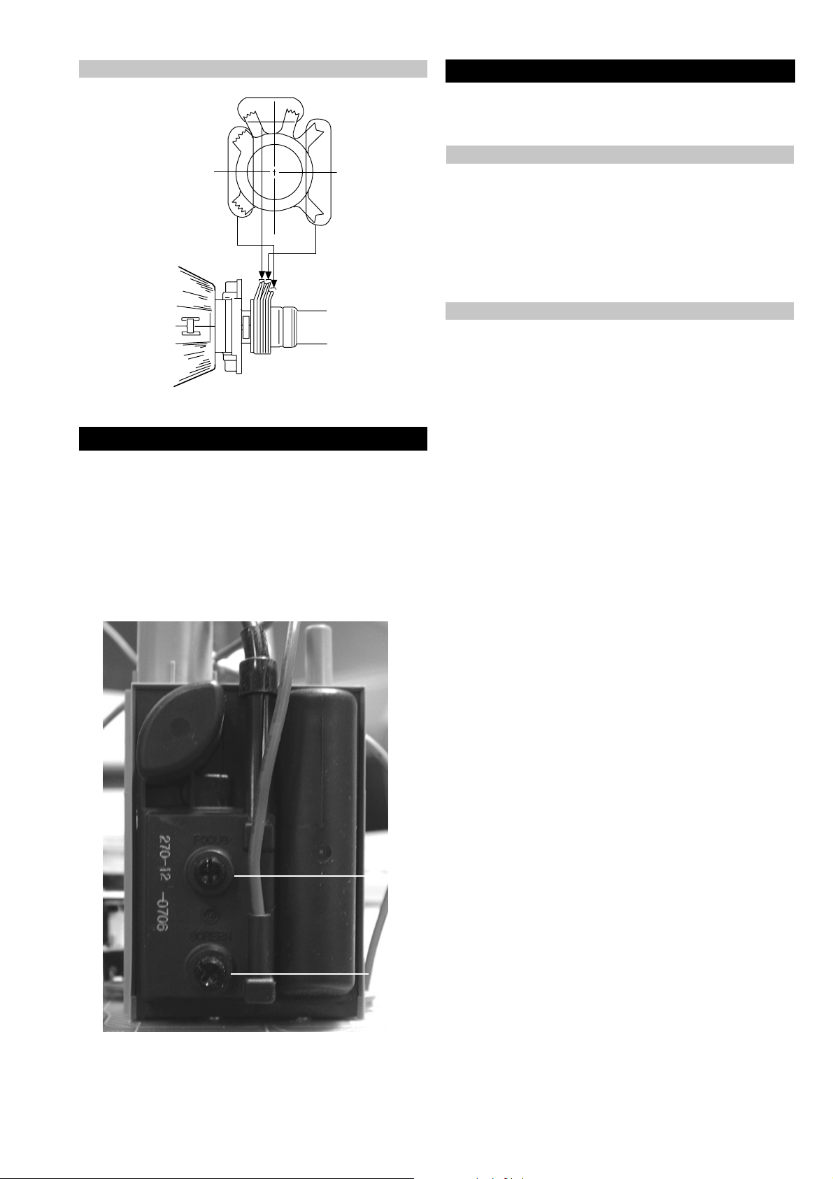
3-3. Focus Adjustment
1. Receive a television broadcast signal.
2. Normalize the picture setting.
3. Adjust the focus control located on the flyback transformer
to obtain the best focus at the centre of the screen.
Bring only the centre area of the screen into focus, the
magenta-ring appears on the screen. In this case, adjust the
focus to optimize the screen uniformly.
3-4. Screen (G2), White Balance
[Adjustment in the service mode using the remote
commander]
G2 adjustment
1. Input a dot signal from the pattern generator.
2. Set the Picture, Brightness and Colour to minimum.
3. Apply 175V DC from an external power supply to the R,G and
B cathodes of the CRT.
4. Whilst watching the picture, adjust the G2 control [SCREEN]
located on the Flyback Transformer to the point just before the
flyback return lines disappear.
White balance adjustment for TV mode
1. Input an all-white signal from the pattern generator.
2. Program the Remote Commander for operation in Service Mode.
[ See Page 24 ]
3. Enter into the ‘Service Mode’ by pressing ‘VIDEO’, ‘VIDEO’
and ‘MENU’ ‘MENU’ on the Remote Commander.
4. Select ‘Device Register Setting’ > ‘Backend’ from the on screen
menu display .
5. Set the ‘Contrast’ to MAX.
6. Set the ‘R-Drive’ to 25.
7. Adjust the ‘G-Drive’ and the ‘B-Drive’ so that the white
balance becomes optimum.
8. Press the ‘OK’ button to write the data for each item.
9. Set the ‘Contrast’ to MIN.
10. Adjust the ‘G-Cutoff’, and the ‘R-Cutof f’ with the left and
right buttons on the remote commander so that the white
balance becomes optimum.
11. Press the ‘OK’ button to write the data for each item.
Focus
Screen
- 23 -
SECTION 4 CIRCUIT ADJUSTMENTS
4-1. Electrical Adjustments
Service adjustments to this model can be performed using the
supplied remote Commander RM-933 (KD-32DX100U)
and RM-935 (KD-32NX100U/ KD-32NS100B).
Programming the Remote Commander for Operation in Service Mode
1. Press the VCR/TV/DVD button until the
TV LED lights.
2. Press and hold the yellow button for
approx. 5 seconds until the TV LED
flashes quickly .
3. Press 99999. All three LED’s should light.
The remote commander is now set to Service Mode.
4. To return the remote commander to normal operation mode
repeat steps 1. and 2. then press 00000. All three LED’s
should light.
The remote commander is now set to normal mode.
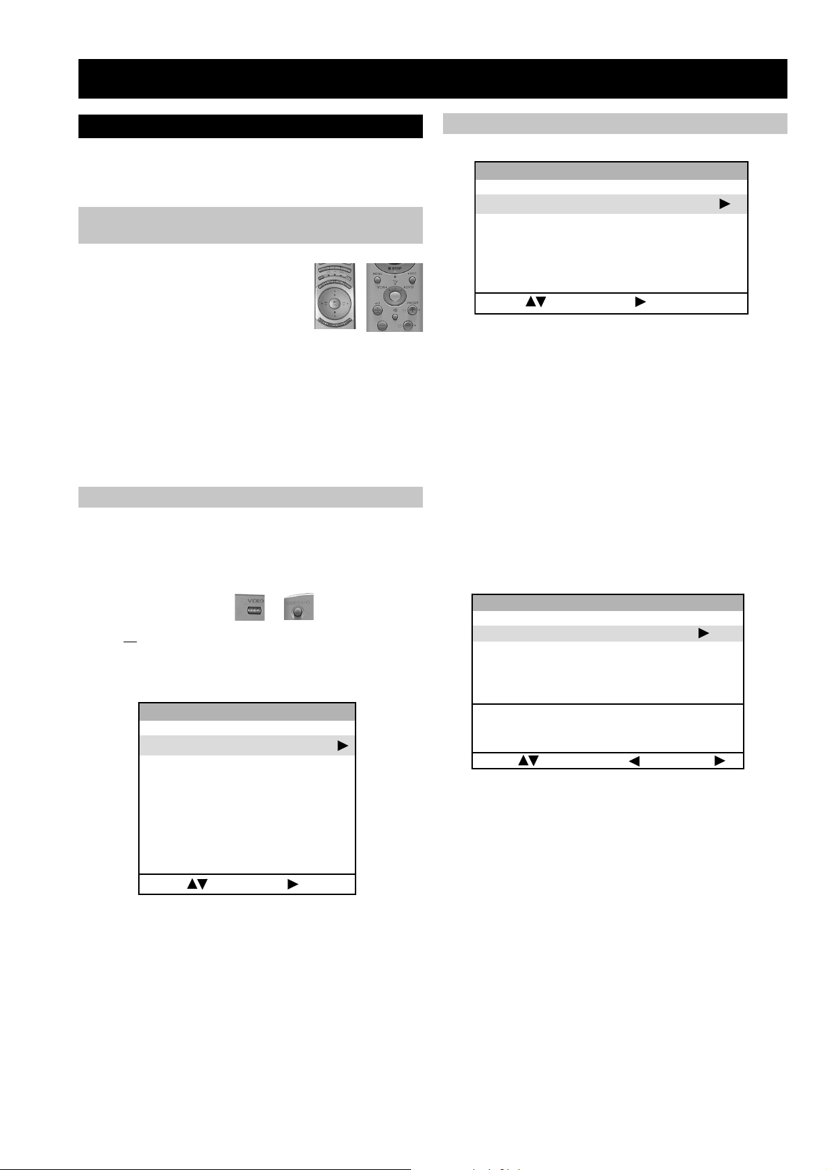
Setting the TV into Service Mode
1. Program the remote commander for operation in Service
Mode as described above.
Initialising Menu
gnisilaitinI
gnitteSledoM
gnitteSnoitanitseD
gnitteScisaB
gnitteSerutaeF
:tceleS:unemtxeN
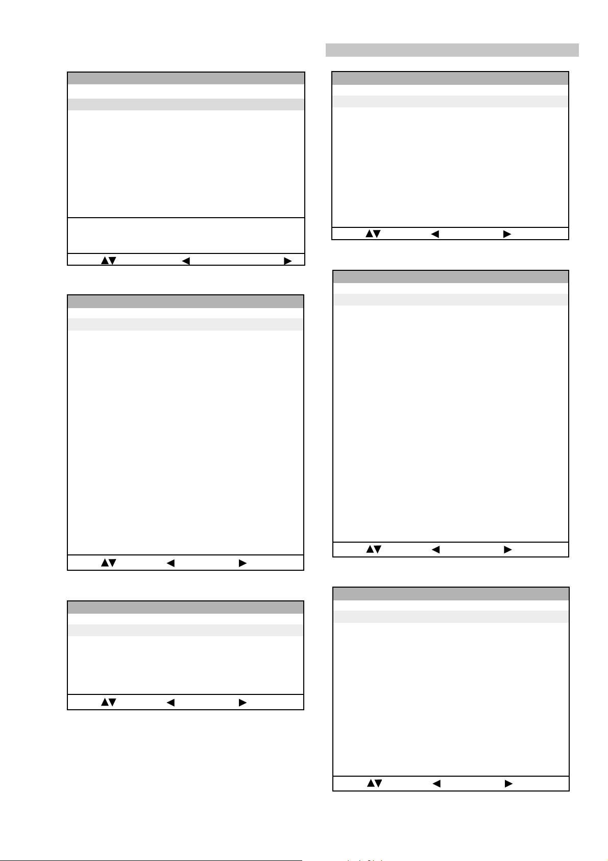
Model Setting
The menu contains a list with all the available models of this
software to set up the TV set in an easy way. The selection
of a model is setting data for its features and hardware
resources which cannot be detected by the automatic power
on H/W detection as well as a special model byte to get an
unique model identification for models which cannot be
differed by features and hardware resources
(e.g. KD-32DX100U and KD-32NX100U).
Before data is set, the user will be asked if he really wants to
set a new model. If the user agrees, the destination setting
menu is automatically shown.
2. Turn on the TV main power switch.
3. Press the ‘VIDEO’ button or on the remote
commander twice.
‘TT ’ will appear in the upper right corner of the screen.
4. Press the ‘MENU’ button on the remote commander twice
to obtain the following menu on the screen.
3S094v,100262luJ,D6EAecivreS
gnisilaitinI
seciveDteseR
gnirotinoM
gnitteSretsigeReciveD
tnemtsujdAlaicepS
:tceleS:unemtxeN
5. Move to the corresponding adjustment item using the
up or down arrow b uttons on the Remote Commander.
6. Press the right arrow button to enter into the required menu item.
7. Press the ‘Menu’ button on the Remote Commander to quit the
Service Mode when all adjustments have been completed.
Note :
• Before performing any adjustments ensure that the correct model
has been selected in the ‘Model Setting’ menu.
• After carrying out the service adjustments, to prevent the
customer accessing the ‘Service Menu’ switch the TV set
OFF and then ON.
gnitteSledoM
teseR001XN23-DK
001SN23-DK
001XD82-DK
001XD23-DK
ytimrofnoCoN=KCALB
ledoMelbitapmoC=NEERG
atadllarofytimrofnoC=DER
:tceleS:unemtsaL:ledoMteS
Indication of Model Compatibility.
Black:
If any data does not match to specific model, the model name
is displayed in black.
Green:
All data which is checked by model setting menu concurs to
model except model byte.
Red:
All data which is checked by model setting menu concurs to
model including model byte.
Note:
After selecting a model, it may be necessary to reset some
devices to get the correct data. (Treble/Bass Offset of Sound,
deflection adjustments, ...)
- 24 -
gnitteSretsigeReciveD
dnekcaB
noitcelfeD
noitcelfeDtxE
ecnegrevnoCcimanyD
1redoceDruoloC
hctiwSoediV/oiduA
X-diM
X-diMLLPlanretxE
pihCyarrAetaG
dnuoS
:metIretnE:unemtsaL:tceleS
gnitteSnoitanitseD
A
B
D
E
K
R
U
ytimrofnoCoN=KCALB
ledoMelbitapmoC=NEERG
:tceleS:unemtsaL:ledoMteS
Device Register Setting
teseRitluM
atadllarofytimrofnoC=DER
hctiwSoediV/oiduA
gnitteScisaB
oN rcseD niM xaM ataD
1G/B.sySFFONONO
2K/D.sySFFONONO
3L.sySFFONONO
4)KU(I.sySFFONONO
5)LRI(I.sySFFONONO
6noitpo.taNTXT143
7TRC9:61FFONONO
8refoow-buSFFONONO
9yb-dnatsotuAFFONONO
01retlif-bmoCFFONONO
11tedCYotuAFFONONO
21tedbmocotuAFFONONO
31elbaliavA2VAFFONONO
41elbaliavA3VAFFONONO
51elbaliavA4VAFFONONO
61raer&rF3VAFFONOFFO
71epaTMACESFFONONO
81etuMdnuoS1VAFFONOFFO
:metIretnE:unemtsaL:tceleS
gnitteSerutaeF
oN rcseD niM xaM ataD
1PAPFFONOFFO
2TAPFFONOFFO
3XEDNIFFONOFFO
4GPEFFONONO
:metIretnE:unemtsaL:tceleS
oN rcseD feD niM xaM ataD
11TUOVC0090
22TUOVC2092
3WS1DGFFOFFONOFFO
4WS2DGFFOFFONOFFO
51TUOCY0070
62TUOCY1071
7LRTC0OLFFOFFONOFFO
8LRTC1OLFFOFFONOFFO
91TUOA3073
012TUOA3073
11ETUM3TUOAFFOFFONOFFO
21WSDCZNOFFONONO
313TUOA3073
41LEDPUORG5101351
51R/L3TUOA0030
61FLOV3TUOA0070
71CLOV3TUOA3073
811CNYS1011
912CNYS1011
oN rcseD feD niM xaM ataD
1TRAMSFFOFFONOFFO
2evruCMOR0010
3DPCADFFOFFONOFFO
41LLITSV0010
51S0010
60S0010
7LCDV1011
8WSFF1011
9IKP1011
01HF1011
11VF1011
21tesFFOH051-510
- 25 -
:metIretnE:unemtsaL:tceleS
pihCyarrAetaG
:metIretnE:unemtsaL:tceleS
dnekcaB
oN rcseD feD niM xaM ataD
1no-RNOFFONONO
2no-GNOFFONONO
3no-BNOFFONONO
4loc-D0030
5wS-bWFFOFFONOFFO
6L-ammaGFFOFFONOFFO
7tsartnoC0403634
8mottoB-KLB3032
9euH0203623
01sixA-ruoloC1031
11ruoloC1303613
21leveL-ITC2032
31ssenthgirB5203613
41lbA-S0030
51ssenprahS5203603
61leveL-ITL0030
71evirD-R5303634
81lvL-timiLP3033
91evirD-G1403614
02edoM-LBA0030
12evirD-B1403614
22edoM-ITC0030
32thgirBbuS603613
42ammaG0033
52ffotuC-R1303613
62edom-ITL0030
72ffotuC-G1303613
82leveL-CIPD1031
92ffotuC-B1303613
03narT-CD0030
13tnoC-buS70517
23lvL-2BGRL80518
33lbA-P5105151
43HT-LBA00510
53tesffo-BC1303613
63W-gnigAFFOFFONOFFO
73B-gnigAFFOFFONOFFO
83tesffo-RC1303613
93metsyS1031
04tesffo-Y70517
14leveL-MV2032
24OFprahSNOFFONONO
34ffO-DCFFOFFONOFFO
44DCprahS0030
541FprahS0030
64revO/erP2032
74roC-MV0031
840F-MV0030
94timiL-MV0030
05yaleD-MV2031
15ruoloCbuS08-80
:metIretnE:unemtsaL:tceleS
1redoceDruoloC
oN rcseD feD niM xaM ataD
1tniT1303613
2wGN/PFFOFFONOFFO
3DIN/PFFOFFONOFFO
4ruoloCbuS70517
5rtnoCbuS80518
6OFprahS1031
7QEprahS2032
8niaGprahS90518
9veLtuO-Y5303653
01tnioPSB0030
11veLtuO-C5403654
21tseRCD0030
31OFFPB1031
41QFPB1031
51wSretliFFFOFFONOFFO
61wSparT-C1010
71parTD-SNOFFONONO
81FPLNOFFONONO
91LD-Y80018
02bmoC-NNOFFONONO
12leSoediV00510
22leSBGR0030
32enoTflaHFFOFFONOFFO
421.FFOrC70517
521.FFObC70517
622.FFOrC70517
722.FFObC70517
82qerFDCV3073
92edoMDCV1031
03SNESCFA1031
13MVMFFOFFONOFFO
23jdAY-RS60516
33jdAY-BS40514
43FPH/LLEB2032
53OFLLEBFFOFFONOFFO
63PGS0030
73DISFFOFFONOFFO
83BNE1BGRFFOFFONOFFO
93HP-SH0010
04WSotuA1031
14HP-PV0010
24OITARN/S3033
:metIretnE:unemtsaL:tceleS
noitcelfeD.txE
oN rcseD feD niM xaM ataD
1esahPFD5810552581
2esahPPQD5210552521
3raeniLdiM5310552661
4lvLcaPQD6210552421
5lvLcdPQD6210552611
:metIretnE:unemtsaL:tceleS
- 26 -
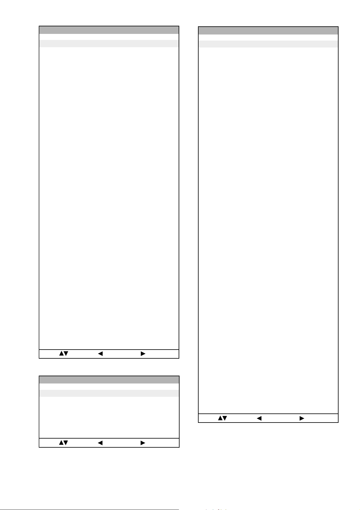
noitcelfeD
Deflection System Adjustment
1. Program the Remote Commander for operation in Service Mode.
oN rcseD feD niM xaM ataD
1eziS-H1303683
2noitisoP-H2203651
3eziS-V0203671
4noitisoP-V1303672
5pmA-niP1303692
6nipC-pU1303672
7nipC-oL1303693
8woB-CFA703604
9elgnA-CFA703652
01esahP-niP1303632
11niL-V70517
21rroC-S70515
311-noitatoR1030
412-noitatoR510517
51parT-H10138
61raeniLH58055258
71pmA-raP-CH003673
81pmA-raP-PM30517
91sixAniPpU3032
02sixAniPoL3032
12niaGniPpU3030
22niaGniPoL3030
32miT-BKA5101351
42ffO-KLBFFOFFONOFFO
52ffO-BKAFFOFFONOFFO
62klB-pU00510
72klB-oL00510
82nO-VNOFFONONO
92cD-wEFFOFFONOFFO
03loP-cUFFOFFONOFFO
13wS-klbVFFOFFONOFFO
23esahP-cnyS0030
33edoM-CFA2032
43wS-tsRFFOFFONOFFO
53klB-tfeL2503625
63esahP-plC3033
73klB-thgiR80368
83etaG-plCFFOFFONOFFO
93wS-klbHFFOFFONOFFO
04tcepsA-V00360
14wS-mooZFFOFFONOFFO
24wS-pmJFFOFFONOFFO
34llorcS-V1303613
44qerF-V2032
54nilV-pU00510
64nilV-oL00510
74pmoC-V00519
84pmoC-H00510
94cD-1waSV70517
05pmoC-niP0070
15pmA-1waSV80130
25pmoC-CFA2032
35cD-raP-PM20512
45cD-raP-CH1303613
55wS-psAFFOFFONOFFO
65wS-vrDVFFOFFONOFFO
75ahP-raP-CH1303613
[ See Page 24 ] and enter into ‘Service Mode’ by pressing
‘VIDEO’ button twice. Enter into the ‘Device Register Setting’
then ‘Deflection’ service menu.
2. Select and adjust each item in order to obtain the optimum image.
4-2. Volume Electrical Adjustments
Sub Colour Adjustment
1. Input a PAL colour bar signal.
2. Connect an oscilloscope to CN5400 pin 5 located on the C
Board.
3. Program the Remote Commander for operation in Service Mode.
[ See Page 24 ] and enter into ‘Service Mode’ by pressing
‘VIDEO’ button twice. Enter into the ‘Device Register Setting’
then ‘Backend’ service menu.
4. Adjust ‘Sub Colour’ data so that the right sides of the waveform
are of equal height.
V SIZE
V LIN
AFC BOW
V POSITION
H POSITION
H SIZE
PIN AMP
PIN PHASE
UP-CPIN
AFC ANGLE
LO-CPIN
Same Level
:metIretnE:unemtsaL:tceleS
B-Out Waveform
- 27 -
4-3. TEST MODE 2:
Test Mode 2 is a vailable by programming the remote commander for operation in service mode (see page 24) and pressing the ‘VIDE O’ button
twice, OSD ‘TT’ appears. The functions described below are av ailable by selecting the two numbers. To release the ‘Test mode 2’, press ‘0’
twice or switch the TV set into Stand-by mode.
00
10
20
30
40
50
60
70
80
01
11
21
31
41
51
61
71
81
91
02
12
22
32
42
52
62
72
82
03
13
23
33
43
53
63
73
83
93
04
14
24
34
44
54
64
74
84
94
05
15
25
35
ffoedom'TT'
mumixamerutciP
muminimerutciP
)enohpdaeh/rekaeps(%03=emuloV
)enohpdaeh/rekaeps(%05=emuloV
)enohpdaeh/rekaeps(%56=emuloV
)enohpdaeh/rekaeps(%08=emuloV
edomgniegA
noitidnoCgnippihS
noitcnufoN
tnemtsujdaerutcipbuS
tnemtsujdaruolocbuS
noitaregifnoctesVTdnanoisreverawtfosyalpsiD
noitcnufoN
tsetnoitatoRerutciP
%05levelerutciP
noetumoiduA
noitcnufoN
tnemtsujdassenthgirbbuS
noitcnufoN
AnoitanitseD
LnoitanitseD
EnoitanitseD
UnoitanitseD
DnoitanitseD
BnoitanitseD
KnoitanitseD
RnoitanitseD
noitcnufoN
1tnemtsujdAyrtemoeG
2tnemtsujdAyrtemoeG
rotinomrorrE
noitcnufoN
sutatsVTyalpsiD;9:61><3:4TRC
hctiwsnoitceted32eniL
tset)MV(noitaludoMyticoleV
noitcnufoN
noitcnufoN
noitcnufoN
kcehcedomneercS
)99margorp(yrtemoegesilaitini-eR
noitcnufoN
001CRD
05CRD
rednammocrelaedrofdevreseR
)99margorp(MVNesilaitini-eR
nigrivnonsaMVNteS
nigrivsaMVNteS
noitcnufoN
noitcnufoN
noitcnufoN
noitcnufoN
45
55
65
75
85
95
06
16
26
36
46
56
76
86
96
07
17
27
37
47
57
67
77
87
18
28
38
48
58
68
78
88
09
19
29
39
49
59
69
79
89
99
noitcnufoN
noitcnufoN
noitcnufoN
noitcnufoN
rotcennocecivresotatadMVNdneS
rotcennocecivresmorfatadMVNteS
noitcnufoN
edomecivreS
edomnoitcudorP
MORmorfatadMVNtesererutcipteS
erutciplautcamorfatadMVNtesererutcipteS
tnemtsujda
sedocrorreteseR
teserdraobN
nosrorreerongI
ffosrorreerongI
noitcnufoN
lanretxe/AMARONAPfosetadtluafedypoC
MVNotniMORmorfXDIM/DIM/LLP
tsetknilVA
slebalnoitatslladna5-1tpecxesemmargorpllaraelC
,DIMrofniPrenroCreppU/pmANIProftnemtsujdA
edom10521dnaGPE
,DIMrofdiozeparT/niPrenroCrewoLroftnemtsujdA
edom3:4&TRAMS,10521,GPE
edom10521rofniPMroftnemtsujdA
kcehcretsooBerutciP
etumoedivoN
edomyalpsidREB
edomrotinomVA
k8&k2,k8,k2
raelcMORPEE
tamrof-ermetsyseliF
srehto/d2EF
teserDIlanosreP
gnippihslatigiD
noitcnufoN
htiw)noitcelfeD.txE/esahPsucoF(tnemtsujdasucoF
nottubkcitsyojthgirdnatfel
.txE/esahPsucoFleveLCD(tnemtsujdasucoF
nottubkcitsyojthgirdnatfelhtiw)noitcelfeD
ylnopuorgerawtfosrofdevreseR
00ybdesaeler,dnammoctsetedomXEDNI
FFO/NOetumDSO
eludomIChguorhtssapST
dnammoctsetTTlatigiD
elbasid/elbaneyrevocerAMME
00ybdesaeler,kcehcrekaepS
- 28 -
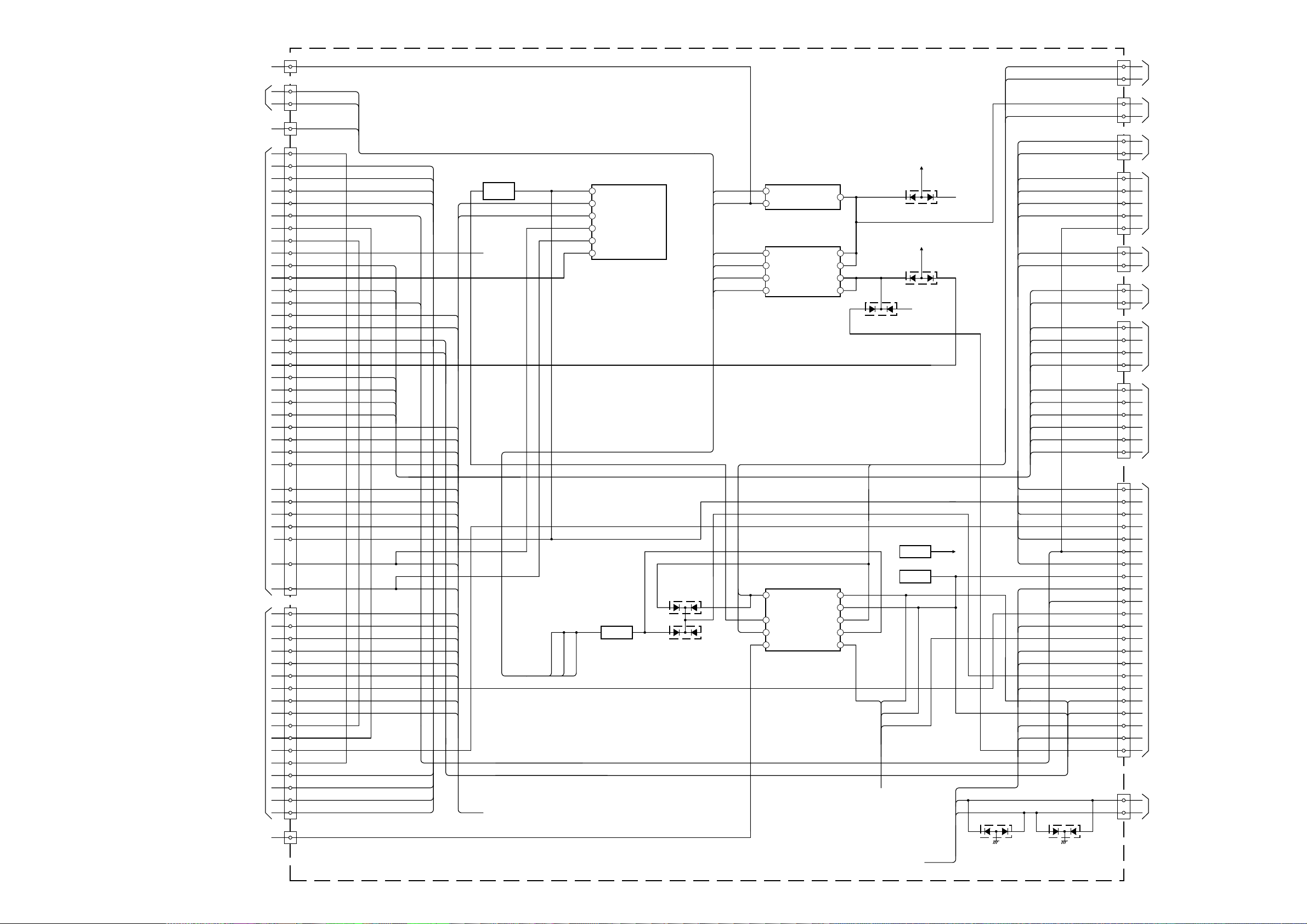
5-1. BLOCK DIA GRAMS (1)
RIGHT SP
A 1/3 (
)
PIC/SOUND
CN2000
1 15
IC1008
I/O EXPANDER
OCP
TO G BOARD
CN6006
12
13
OVP
CN1602
MAIN RY
TO G BOARD
CN6008
1
2
DGC RY
CN1703
KEY 2/SCL 3.3
TO FRONT
CONTROL
(3 PIN)
1
3
KEY 1/SDA 3.3HM(2)
HM(1)
CN1706
KEY 2/SCL 3.3
1
3
KEY 1/SDA 3.3HM(2)
HM(1)
5
SIRCS/AV INTHM(4)
6
RESP LED/RESETHM(3)
7
AV LINK
CN1702
SIRCS
TO H6 BOARD CN7100
(KD-32DX100)
TO H2 BOARD CN7150
(KD-32NS100/32NX100)
3
4
LEDHM(3)
HM(4)
CN7107
HEADPHONE R OUT
TO H3 BOARD
CN7104
1
3
HEADPHONE L OUTHP L
HP R
CN7108
AV4 CHROMA IN
TO H1 BOARD
CN7103
1
3
AV4 LUMINANCE INAV4 Y
AV4 C
AV4 LEFT IN
5
AV4 L
AV4 RIGHT IN
7
AV4 R
CN1701
HEADPHONE R OUT
TO H5 BOARD
CN7103
1
3
HEADPHONE L OUTHP L
HP R
5
AV4 C
7
AV4 LEFT IN
9
AV4 L
AV4 RIGHT IN
11
AV4 R
AV4 CHROMA IN
AV4 LUMINANCE INAV4 Y
CN1000
KEY 2
TO M3 BOARD
CN9501
4
5
CPU BUSY IN
HM (1)
6
HM (2)
7
RESP LED
8
HM (3)
AV LINK
9
KEY 1
INT COL
10
HM (4) SIRCS
13
SDA 0
AUDIO RESET
15
CK TEXT VIDEO
17
RESET 100
19
TXTBLK
21
TC LED
22
TXTB
23
BLK MB
TXTG
25
PROT
26
TXTR
27
SCL DIG
29
SDA DIG
31
VP 100
33
HP 100
35
AUDIO MUTE
39
B MB
G MB
R MB
SDA 1
SCL 1
SDA 1
SCL 1
D1008
CN1999
SCL
TO SERVICE
2
3
SDA
D1009
Q1010
Q1009
+9V
OV PROT SCL
14
SDA
3 10
PORT 2 OC PROT
4 9
DGCRY GND AUDIO PROT
5 7
PWR N RESET
CN1203
LEFT SP
1
1
3
CN1201
CN1202
1
WOOFER SP
TO SPEAKER
TO
SUBWOOFER
V PULSE IN
FBLK
3
5
CN1001
TO J BOARD
CN8805
Y MAIN IN
7
U MAIN IN
9
V MAIN IN
10
SUB C
13
SUB Y
14
D CVBS OUT
16
AV4 C OUT
17
ATV CV OUT
18
AV4 Y OUT
19
AV LINK
21
SDA
23
SCL
24
SDA 1
25
SCL 1
26
HP MUTE
31
CVBS TXT
11
HP A IN
33
HP L IN
34
AV4 R OUT
35
AV4 L OUT
36
DTV R OUT
39
DTV L OUT
40
TV R OUT
41
TV L OUT
42
ATV R OUT
43
ATV L OUT
44
MAIN R IN
45
MAIN L IN
46
AGC MON
QSS
49
AM
50
HP 100 IN
VP 100 IN
11
12
CN7109
TO B4 BOARD
CN502
Y 100 IN
14
U 100 IN
16
V 100 IN
18
DPIC
20
RESET 100
22
SCL
23
SDA
24
VP SUB OUT/Y SUB
31
V SUB OUT/C SUB
34
U SUB OUT/INT COL
36
Y SUB OUT/FB
38
Y MAIN OUT/B
42
U MAIN OUT/G
44
V MAIN OUT/R
46
VP LSE M/Y M
48
CN1604
TO G1 BOARD
CN4602
10
ACTIVE PWR
AV4 C
AV4 Y
HP R
HP L
AV4 R
AV4 L
DTV R
MAIN Y
MAIN U
MAIN V
V PULSE
N RESET S CL TV
SDA TV
EMM ISO
D1003
OVP
AGC DEF
D1004
AV PROT
OCP
Q1003
LEFT SP
RIGHT SP
WOOFER SP
1
10
IC1201
AUDIO AMPLIFIER
WOOFER
OUTPUT
STBY/MUTE
9
INPUT
WOOFER SP
WOOFER
1
9
IC1202
AUDIO AMPLIFIER
LEFT AND RIGHT
OUT S
STBY
3
OUT C
RIGHT SP
LEFT SP
14
STBY
13
6
IN S+
MUTE
8
IN C+
RIGHT
LEFT
11
MUTE
D1205
D1203
D1204
TU1001
MAIN TUNER
AGC
SCL
SDA
QS
FM/AM
VIDEO
SWITCH
Q1207
+11V
+11V
TO SHEET 3
TO SHEET 2
TO SHEET 3
TO SHEET 2
V PULSE
MAIN Y
MAIN U
MAIN V
CV TEXT
DTV L
TV R
TV L
ATV R
ATV L
MAIN R
MAIN L
V SYNC 100
H SYNC 100
Y 100
U 100
V 100
SWITCH
48
DCVBS
I2C BUS SW
I2C BUS SW
AV MUTE
H SYNC 100
V SYNC 100
- 29 -
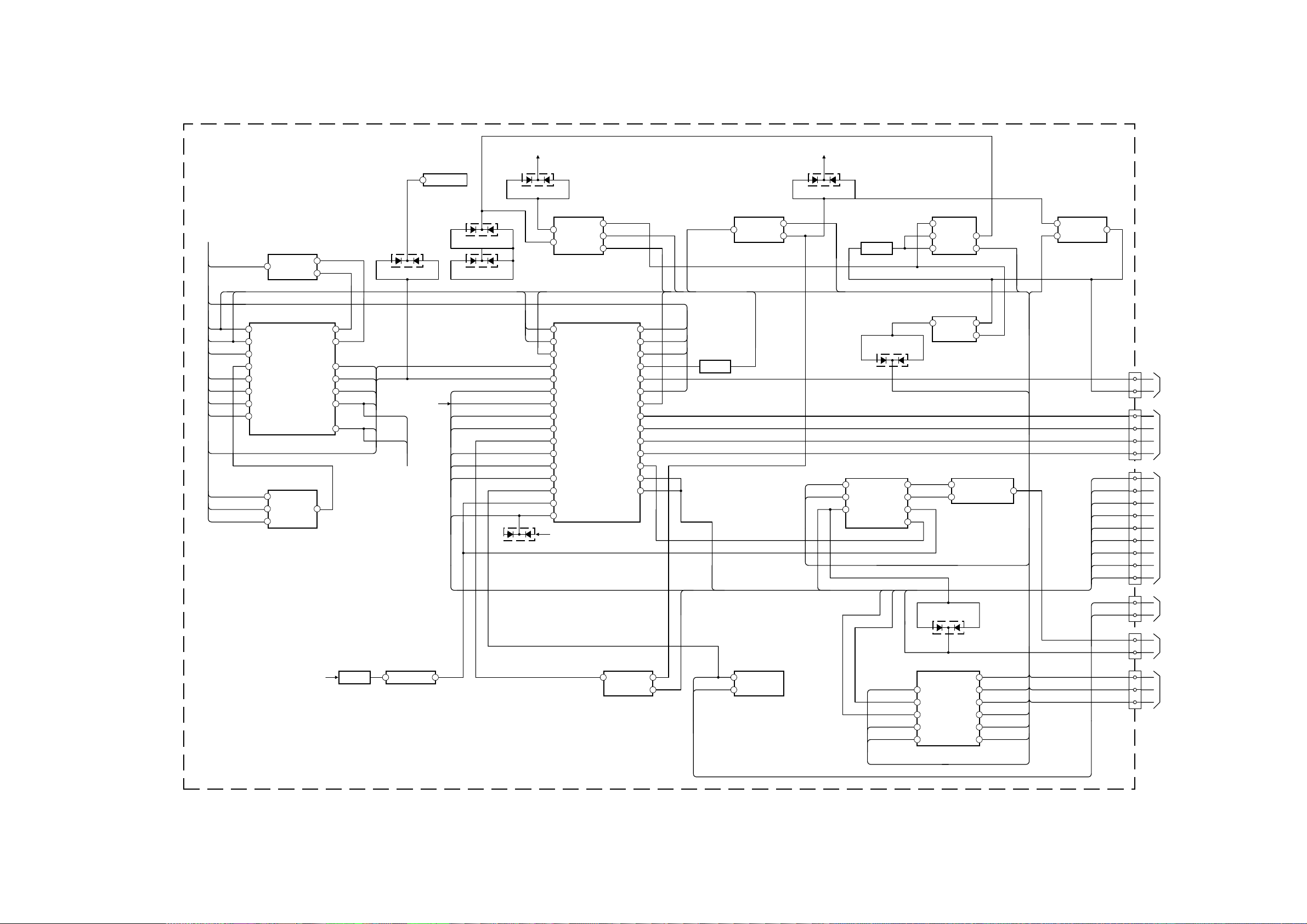
5-1. BLOCK DIA GRAMS (2)
CN1803
VM
TO VM BOARD
CN5602
1
4
QP-
CN1804
Q1809
+12V
4
11
IC1803
D/A CONVERTER
9
DQP AC MOD
HC DC
12
7
58
10
D1814
R OUT
TO C BOARD
CN5400
1
3
G OUT
B OUT
5
8
IK
CN1805
DF PARA
TO D BOARD
CN8620
1
2
MP PARA
3
E/W
4
HC PARA
5
H DRIVE
6
AFC PULSE
ABL
7
X-RAY
8
ZOOM COMP
10
CN1901
VM
TO ROT COIL
1
3
QP-
CN1902
CY +
TO CY
1
3
CY-
CN1807
PRE RGB
TO D BOARD
CN8810
1
2
DF DRIVE
3
H CENTRE
3 20
H CENTRE
DQP V PARABOLA
AC AMP SET LEVEL
SCL
21
SDA
DF FOCUS PHASE
MP DC
DQP DC LEVEL
DQP VDC MOD
HC PARA
MP PARA
2
IC1809
CONVERGENCE AMPLIFIER
3
6
17
5
IC1806
DYNAMIC CONVERGENCE CONTROL
16
6
10
2
3
SCL
SDA
AFC PULSE
ABL
2
IC1804
QP CONTROL
3
1
D1814
DQP VDC MOD
1
IC1808
QP CONTROL
5
2
DQP DC LEVEL
2
IC1811
QP OUTPUT AMPLIFIER
4
7
6
1
AC AMP SET LEVEL
2
IC1805
6
5
DQP AC MOD
D1803
DQP V PARABOLA
1
IC1801
DF, DQP PHASE CONTROL
6
7
3
5
DF DRIVE
DF FOCUS PHASE
D1802
D1801
+5V
D1811
25
IC1402
BACKEND BLOCK RESPONSIBILITY
20
SDA Y IN
26 21
SCL CB IN
27 22
SCP CR IN
28
15
HS IN
VM MOD
34
14
HPROT
VM OUT
35
12
VPROT
DPOT OFF
39
60
HP IN
PRE RGB
40
64
H DRV
R OUT
43
63
HC PARA
G OUT
45
62
MP PARA
B OUT
46
58
DF PARA
IK IN
47
52
EW DRV
V DRV-
51
37
VSAW 1
VCOMP IN
53
36
V DRV+
HCOMP IN
56
42
ABL IN
VS IN
Y 100
U 100
V 100
DPIC
PRE RGB
Q1405
SWITCH
ZOOM COMP
D1403
+9V
X-RAY PROT
AFC PULSE
H DRIVE
SIGN1736
EW
ABL
V-
V SYNC 100
H SYNC 100
D1401
2
IC1401
BACKEND BLOCK
RESPONSIBILITY
IC1905
ROTATION (N/S)
6
5
ROT-
ROT+
IC1802
PARABOLA AMPLIFIER
5 1
3
DF PARA
IC1701
VERTICAL DEFLEC TION
OUTPUT
5 7
Q1701
AMP
V+
2 69
SDA IF IN 2
3 67
SCL IF IN 1
21
60
POWER ON RESET
MONO IN (AM)
33 57
SC2 OUT R SC1 IN R
34 56
SC 2 OUT L SC1 IN L
36 54
SC1 OUT R SC2 IN R
37
53
SC1 OUT L
SC2 IN L
30
SUBWOOFER OUT
IC1231
AUDIO ALEX
AM
MAIN R
MAIN L
DTV R
DTV L
ATV L
ATV R
TV L
TV R
AUDIO RESET
IC1270
OUTPUT AMP
1
37
8
AUDIO WOOFER
AUDIO LEFT
AUDIO RIGHT
FL1270
4
1
QSS
3
TO SHEET 3
TO SHEET 1
A 2/3 ( )
PIC/SOUND
QP OUTPUT
SWITCHING FET
- 30 -
 Loading...