

Page 1

SERVICE MANUAL
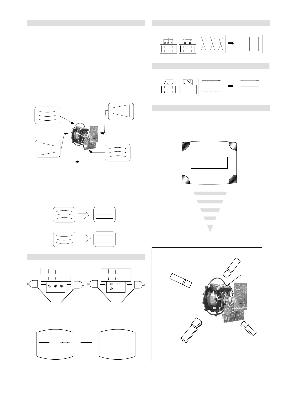
FE-2D
CHASSIS
MODEL
KD-28DL11U
COMMANDER DEST CHASSIS NO.
RM-949 UK SCC-Q52X-A
KD-28DL11
- 1 -
RM-949
Page 2

TABLE OF CONTENTS
Section Title Page Section Title Page
Caution .................... 3
Specifications .................... 4
Connectors .................... 5
Self Diagnostic Software .................... 6
1. GENERAL
Automatically Tuning the TV .................... 7
Finding the Video Channel .................... 7
Selecting digital and analogue mode ............. 7
Digital Text .................... 7
Analogue Text .................... 8
The Digital electronic programme guide ....... 8
Using the TV Menu System .................... 9
Detail Set-up Menu .................... 10
Connecting other Equipment to the TV ........ 10
Viewing pictures from a connected VCR ...... 10
Viewing pictures from equipment
connected to the rear sockets .................... 10
Viewing pictures from equipment
connected to the front sockets .................... 10
Specifications .................... 11
Troubleshooting .................... 11
2. DISASSEMBLY
2-1. Rear Cover Removal .................... 12
2-2. Chassis Removal and Refitting .................... 12
2-3. A Board Removal [Step 1] .................... 13
2-4. A Board Removal [Step 2] .................... 13
2-5. F3 Board Removal .................... 13
2-6. A1 Board Removal .................... 14
2-7. Service Position .................... 14
2-8. N Board Removal .................... 14
2-9. Picture Tube Removal .................... 15
Bottom Plates .................... 16
3. SET-UP ADJUSTMENTS
3-1. Beam Landing .................... 17
3-2. Convergence .................... 18
3-3. Focus Adjustment .................... 20
3-4. Screen (G2), White Balance .................... 20
4. CIRCUIT ADJUSTMENTS
4-1. Electrical Adjustments .................... 21
4-2. Test Mode 2 .................... 23
5. DIAGRAMS
5-1. Block Diagrams (1) .................... 24
Block Diagrams (2) .................... 25
Block Diagrams (3) .................... 26
5-2. Circuit Board Location .................... 27
5-3. Schematic Diagrams and
Printed Wiring Boards .................... 27
* A Board PWB .................... 29
* A Board Schematic .................... 30
* A1 Board PWB .................... 34
* A1 Board Schematic .................... 35
* B1 Board PWB .................... 38
* B1 Board Schematic .................... 37
* F3 Board PWB .................... 38
* F3 Board Schematic .................... 39
* H9 Board PWB .................... 38
* H9 Board Schematic .................... 39
* C Board PWB .................... 41
* C Board Schematic .................... 40
* D2 Board PWB .................... 41
* D2 Board Schematic .................... 40
* VM Board PWB .................... 41
* VM Board Schematic .................... 42
5-4. Semiconductors .................... 43
5-5. IC Blocks .................... 44
6. EXPLODED VIEWS
6-1. Chassis .................... 45
6-2. Picture Tube .................... 46
7. ELECTRICAL PARTS LIST .................... 47
ATTENTION
APRES AVOIR DECONNECTE LE CAP DE’LANODE,
COURT-CIRCUITER L’ANODE DU TUBE CATHODIQUE ET
CELUI DE L’ANODE DU CAP AU CHASSIS METALLIQUE DE
L’APPAREIL, OU AU COUCHE DE CARBONE PEINTE SUR LE
TUBE CATHODIQUE OU AU BLINDAGE DU TUBE
CATHODIQUE.
CAUTION
SHORT CIRCUIT THE ANODE OF THE PICTURE TUBE AND THE
ANODE CAP TO THE METAL CHASSIS, CRT SHIELD, OR THE
CARBON PAINTED ON THE CRT, AFTER REMOVAL OF THE
ANODE CAP.
WARNING !!
AN ISOLATION TRANSFORMER SHOULD BE USED DURING
ANY SERVICE WORK TO AVOID POSSIBLE SHOCK HAZARD
DUE TO LIVE CHASSIS, THE CHASSIS OF THIS RECEIVER IS
DIRECTLY CONNECTED TO THE POWER LINE.
SAFETY-RELATED COMPONENT WARNING !!
COMPONENTS IDENTIFIED BY SHADING AND MARKED
THE SCHEMATIC DIAGRAMS, EXPLODED VIEWS AND IN THE
PARTS LIST ARE CRITICAL FOR SAFE OPERATION. REPLACE
THESE COMPONENTS WITH SONY PARTS WHOSE PART
NUMBERS APPEAR AS SHOWN IN THIS MANUAL OR IN
SUPPLEMENTS PUBLISHED BY SONY.
ON
ATTENTION !!
AFIN D’EVITER TOUT RISQUE D’ELECTROCUTION
PROVENANT D’UN CHÁSSIS SOUS TENTION, UN
TRANSFORMATEUR D’ISOLEMENT DOIT ETRE UTILISÈ LORS
DE TOUT DÈPANNAGE LE CHÁSSIS DE CE RÈCEPTEUR EST
DIRECTMENT RACCORDÈ Á L’ALIMENTATION SECTEUR.
ATTENTION AUX COMPOSANTS RELATIFS Á
LES COMPOSANTS IDENTIFIÈS PAR UNE TRAME ET PAR UNE
MARQUE
EXPLOSÈES ET LES LISTES DE PIECES SONT D’UNE IMPOR-
TANCE CRITIQUE POUR LA SÈCURITÈ DU FONCTIONNEMENT,
NE LES REMPLACER QUE PAR DES COMPSANTS SONY DONT
LE NUMÈRO DE PIÈCE EST INDIQUÈ DANS LE PRÈSENT
MANUEL OU DANS DES SUPPLÈMENTS PUBLIÈS PAR SONY.
SUR LES SCHÈMAS DE PRINCIPE, LES VUES
LA SECURITÈ!!
- 2 -
Page 3
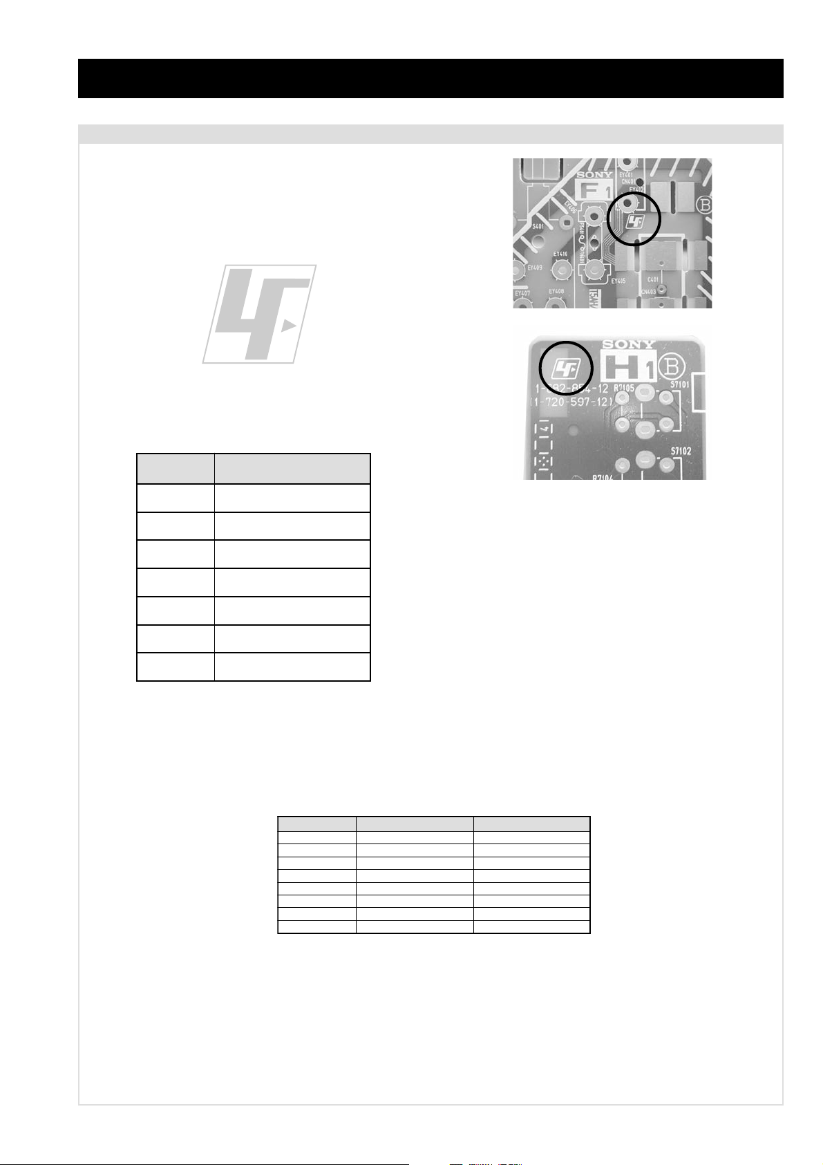
CAUTION
Lead Free Soldered Boards
The circuit boards listed below [Table 1] used in these models may
have been processed using Lead Free Solder. The boards are
identified by the LF logo located close to the board designation e.g.
F1, H1 etc [ see examples ]. The servicing of these boards requires
special precautions to be taken as outlined below.
Table 1
draoB noitcnuF
example 1
example 2
AoiduA,oediV,noitcelfeD,ylppuSrewoP
1AgnissecorPdnEtnorFlatigiD
1BgnihctiwSV,U,Y
CtuOB,G,R
2DnoitcelfeDedoMtramS
3FesuF/tupnICA
MVnoitaludoMyticoleV
It is strongly recommended to use Lead Free Solder material in order to guarantee optimal quality of new solder joints. Lead Free Solder is
available under the following part numbers :
rebmuntraP retemaiD skrameR
91-500-046-7mm3.0gK52.0
02-500-046-7mm4.0gK05.0
12-500-046-7mm5.0gK05.0
22-500-046-7mm6.0gK52.0
32-500-046-7mm8.0gK00.1
42-500-046-7mm0.1gK00.1
52-500-046-7mm2.1gK00.1
62-500-046-7mm6.1gK00.1
Due to the higher melting point of Lead Free Solder the soldering iron tip temperature needs to be set to 370 degrees centigrade. This requires
soldering equipment capable of accurate temperature control coupled with a good heat recovery characteristics.
For more information on the use of Lead Free Solder, please refer to http://www.sony-training.com
- 3 -
Page 4
LEDOMMETI metsySnoisiveleT metsySoeretS egarevoClennahC metsySroloC
UT-BVD/IoeretSMACIN96B-12B:FHUI
LAP
34.4CSTN,85.3CSTN
)NIOEDIV(
LM@PM2-GEPM
ebuTerutciP
skcaJonohP
latigiD
kcajenohpdaeHkcajinimoerets
stupnioiduAskcajonohp
stupnioediVskcajonohp
tupnioediVSNIDnip4
nortinirTDFyalpsiDtalF
)sehcni82(mc17xorppA
.)yllanogaid
]RAER[slanimreTtuptuO/tupnI
rotcennocoruEnip-12:1
)dradnatsCELENEC(
rotcennocoruEnip-12:2
slangiS
.BGRrofstupnI
.slangis
.oediVSrofstupnI
)elbatceles(
kcaJmedoM
AICMCP
]TNORF[slanimreTtuptuO/tupnI
derusaemerutcipmc66xorppA(
.slangisoediVdnaoiduArofstupnI
oiduAdnaoediVVTfostuptuO
.slangisoediVdnaoiduArofstupnI
.slangisoiduAdnaoediVVTfostuptuO
oiduArofelbairavsrotcennoCtuptuO
tuptuodnuoS
rekaepstfeLdnathgiR)SMR(W7x2)rewoPcisuM(W41x2
snoitacificepSlareneG
stnemeriuqeRrewoPV042-022
noitpmusnoCrewoPW79
snoisnemiDmm525x515x097xorppA
thgieWgk34xorppA
seirosseccAdeilppuS
serutaeFrehtO
stnemeriuqerrewoP
)1(rednammoCetomeR949-MR
)2(yrettab6RdetangisedCEI
,txeteleT,FD&PQD,noitcudeResioNotuA
.gninuTputratSotuA,lebaLotuA,kniltramS
lortnoCderarfnI:metsySlortnoCetomeR
cdV3
noitangisedCEIseirettab2
)AAezis(6R
.ecitontuohtiwegnahcottcejbuserasnoitacificepsdnangiseD
metI
emaNledoM
bmoClaPFFO
PIPFFO
ytiroirPBGRNO
xoBrefooWFFO
1tracSNO
2tracSNO
)3(nitnorFNO
4tracSFFO
rotcejorPFFO
G/BmroNFFO
ImroNNO
K/DmroNFFO
SUAmroNFFO
LmroNFFO
TASmroNFFO
MmroNFFO
txeteleTNO
oeretSmaciNNO
WARNING (UK Models only)
U11LD82-DK
The flexible mains lead is supplied connected to a B.S. 1363 fused
plug having a fuse of 5 AMP rating. Should the fuse need to be
replaced, use a 5AMP FUSE approved by ASTA to BS 1362, ie one
that carries the
IF THE PLUG SUPPLIED WITH THIS APPLIANCE IS NOT SUITABLE FOR THE OUTLET SOCKETS IN YOUR HOME, IT SHOULD
BE CUT OFF AND AN APPROPRIATE PLUG FITTED. THE PLUG
SEVERED FROM THE MAINS LEAD MUST BE DESTROYED AS A
PLUG WITH BARED WIRES IS DANGEROUS IF ENGAGED IN A
LIVE SOCKET.
When an alternative type of plug is used, it should be fitted with a
5 AMP FUSE, otherwise the circuit should be protected by a 5AMP
FUSE at the distribution board.
ASA
T
mark.
How to replace the fuse.
Open the fuse compartment with
a screwdriver blade and replace
the fuse.
FUSE
- 4 -
Page 5
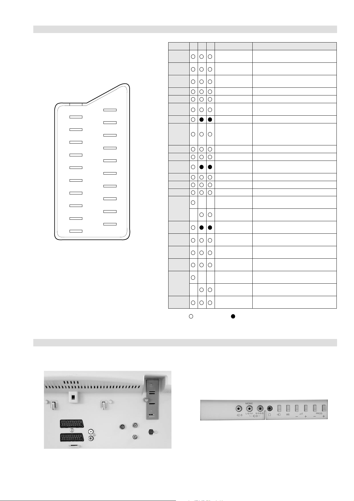
21 pin connector
21
19
17
15
13
11
9
7
5
3
1
20
18
16
14
12
10
8
6
4
2
Pin No 1 2 4 Signal Signal level
1 Audio output B
2
3
4 Ground (audio)
5 Ground (blue)
6 Audio input A
7 Blue input 0.7 +/- 3dB, 75 ohms positive
8 Function select
9 Ground (green)
10 Open
11 Green Green signal : 0.7 +/- 3dB, 75 ohms,
12 Open
13 Ground (red)
14 Ground (blanking)
15
_ (S signal Chroma
16 Blanking input
17 Ground (video
18 Ground (video
19 Video output 1V +/- 3dB, 75ohms, positive sync 0.3V
20
_ Video input
21 Common ground
(right)
Audio output B
(right)
Audio output A
(left)
(left)
(AV control)
_ _ Red input 0.7 +/- 3dB, 75 ohms, positive
input)
(Ys signal)
output)
input)
_ _ Video input 1V +/- 3dB, 75ohms, positive sync 0.3V
Y (S signal)
(plug, shield)
Standard level : 0.5V rms
Output impedence : Less than 1kohm*
Standard level : 0.5V rms
Output impedence : More than 10kohm*
Standard level : 0.5V rms
Output impedence : Less than 1kohm*
Standard level : 0.5V rms
Output impedence : More than 10kohm*
High state (9.5-12V) : Part mode
Low state (0-2V) : TV mode
Input impedence : More than 10K ohms
Input capacitance : Less than 2nF
positive
0.3 +/- 3dB, 75 ohms, positive
High state (1-3V) Low state (0-0.4V)
Input impedence : 75 ohms
(-3+10dB)
(-3+10dB)
1V +/- 3dB, 75ohms, positive sync 0.3V
(-3+10dB)
Connected Not Connected (open) * at 20Hz - 20kHz
Rear Connection Panel Front Connection Panel
- 5 -
Page 6
FE-2D SELF DIAGNOSTIC SOFTWARE
The identification of errors within the FE-2D chassis is triggered in one of two ways :- 1: Busy or 2: Device failure to respond to IIC. In the
event of one of these situations arising the software will first try to release the bus if busy (Failure to do so will report with a continuous
flashing LED) and then communicate with each device in turn to establish if a device is faulty. If a device is found to be faulty the relevant
device number will be displayed through the LED (Series of flashes which must be counted) See table 1., non fatal errors are reported using this
method.Each time the software detects an error it is stored within the NVM. See Table 2.
Table 1
egasseMrorrE
rorreoN00
devreseR10
)noitcetorPtnerruCrevO(PCO20
desUtoN30
cnySlacitreVoN40
norewoptarorrERKI50
norewoptaegdelwonkcasubCIIonMVN70
desUtoN80
norewoptaegdelwonkcaonrenuT90
rorrErossecorPdnuoS01
rorrestlov8rellortnocelgnuJ11
Flash Timing Example : e.g. error number 3
StBy LED
ON
ON ON
norewoptawolsenilatadro/dnakcolcsubCII60
How to enter into Table 2
DEL
edoC
1. Turn on the main power switch of the TV set and enter into
the ‘Standby Mode’.
2. Press the following sequence of buttons on the Remote
Commander.
i+
(ON SCREEN (DIGIT 5) (VOLUME -) (TV)
DISPLAY)
5
-
3. The following table will be displayed indicating the error
count.
Table 2
UNEMRORRE
OFF
OFF
:20E
:30E
:40E
:50E
:60E
:70E
:80E
:90E
:01E
:11E
:21E
:31E
:41E
EMITGNIKROW
SRUOH
SETUNIM
PCO
A/NPVO
CNYSV
RKI
CII
MVN
ELGNUJ
RENUT
PDNUOS
V8
AMME
XETROP
CTR
)552,0(
0
)552,0(
0
)552,0(
0
)552,0(
0
)552,0(
0
)552,0(
0
)552,0(
0
)552,0(
0
)552,0(
0
)552,0(
0
)552,0(
0
)552,0(
0
)552,0(
0
1
22
Note: To clear the error count data press ‘80’ on the Remote
commander.
- 6 -
Page 7
SECTION 1 GENERAL
Many broadcasters now provide a digital text service. Digital text services offer all
the familiar information that analogue (conventional) text services provide but with
the look and feel of a graphically rich website.
The appearance, content and navigation methods of all digital text services are
decided by the broadcaster. For example, digital text from the BBC may look
Digital text
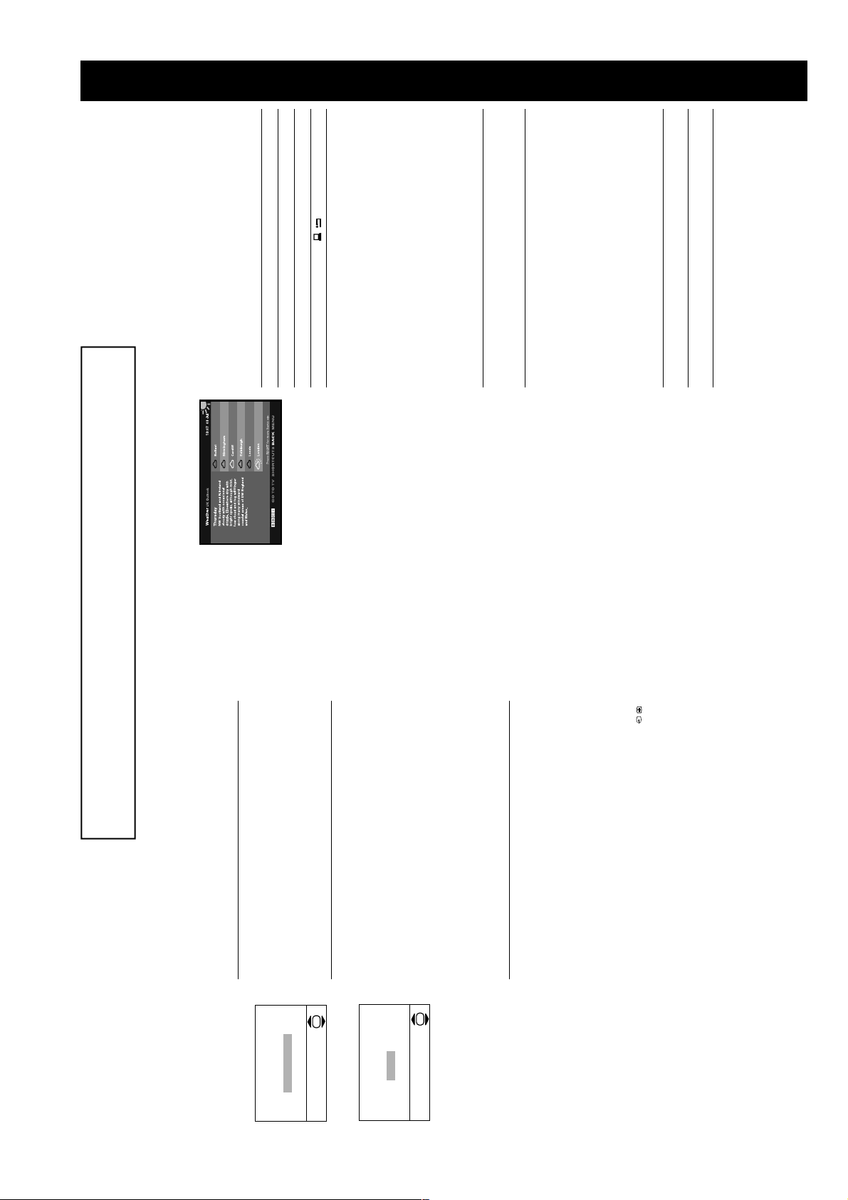
An example of digital text.
or the numbered buttons on the remote control. If you are instructed to
Select a digital channel which provides a text service.2.Press the / button to access the digital text service.3.Follow the on screen instructions.4.Once the text information is displayed, you can access the required
Select items on screen... OK and Numbered buttons.
Cancel a selection/go back a step... / button.
To Press
Load or exit digital text... / button.
different from digital text from ITV. Most of the digital text services currently
available use simple navigation methods based on the following buttons:
Move around the screen... V, v, B or b buttons.
Access shortcuts... Coloured buttons.
Viewing digital text
There are two ways to view digital text, either while watching a digital channel or by
accessing a dedicated digital text channel.
a) Digital text from digital channels
(depending on availability of service)
1.
press ‘OK’ or ‘Select’ when viewing the text pages, press the OK button.
information by using the V, v, B or b buttons, the coloured buttons and/
When you have finished viewing the text service, press the / button to
exit.
5.
b) Digital text from a dedicated digital text channel
(depending on availability of service)
Some broadcasters provide a separate channel for accessing their digital text
service.
Select the programme number that is broadcasting the dedicated digital
text channel by using the numbered buttons on the remote control. If you
1.
do not know the channel number of a dedicated digital text channel, you
this manual).
can use the ‘EPG menu’ to find one (please refer to the ‘EPG’ section of
Once the text page is displayed, follow the on-screen instructions to
2.
obtain your required selection.3.If you are instructed to press ‘OK’ or ‘Select’ when viewing the text pages,
press the OK button.
When you have finished viewing the text service, press the / button to
return to the text front page, or press the PROG+/- button to return to
normal TV operation.
4.
The operating instructions mentioned here are partial abstracts from the ‘Operating
Instruction Manual’. The page numbers of the ‘Operating Instruction Manual’ remain
as in the manual.
The TV has now tuned
in all the available channels
necessary’. Press the OK button to continue.
‘Adjust now’. Press the OK button to continue. Press the V or v button
the remote control to highlight the language you require then press the
OK button to confirm. From now on all menus appear in your chosen
language.
When you switch on the TV for the first time a language menu appears
on screen with the word ‘English’ highlighted. Press the V or v buttons on
The picture rotation prompt now appears asking you to check if the
picture is slanted. (Sometimes the Earth’s natural magnetism can cause
the screen to look slanted.)
a) If no correction is required, press the V or v button to highlight ‘Not
1.
2.
Automatically tuning the TV
adjust picture rotation
If picture slants, please
The ‘Picture Rotation’ menu.
to correct the slant. Press the OK button to store.
b) If some correction is required, press the V or v button to highlight
The autotune prompt appears. Press the OK button to select ‘Yes’. The
autotune procedure begins.
The digital autotune display appears on screen and the TV starts to
search for all the available digital channels. This may take some time,
please be patient and do not press any buttons on the TV or remote
control.
When the digital autotune is complete, the analogue autotune starts to
search for all the available analogue channels.
If no digital or analogue channels are found, a message appears asking
you to confirm that the aerial is connected correctly. Check all the aerial
connections and press the OK button to start the autotune procedure
again.
Once all available digital and analogue channels have been stored, the
TV returns to normal operation, displaying the digital channel stored on
programme number 1. If no digital channels are found, the analogue
channel stored on programme number 1 is displayed.
3.
OK
Adjust now
Not necessary
Do you want to start
The ‘Autotune’ prompt.
OK
No
Ye s
automatic tuning?
Finding your video channel
If you have connected a VCR to your TV when following the ‘Connecting
an aerial and a VCR to the TV’ instructions, you now need to find your
video channel. Press the PROG+/- button until the picture from the pre-
recorded tape appears on screen.
If you have connected your VCR using a scart lead, press the /
button repeatedly until the picture from the pre-recorded tape appears on
screen.
1.
Press the DIGITAL button to switch to digital mode.
In digital mode, an information banner appears briefly on screen when
you change the TV channels.2.Press the a button to switch to analogue mode.
In analogue mode, the channel number appears in green lettering when
you change the TV channels.
1.
Selecting digital and analogue mode
- 7 -
Page 8

RED button (previous), GREEN
button (next).
(see previous page).
The Digital Electronic
The Digital Electronic Programme Guide (EPG) allows you to:
Programme Guide
a) view programme information for all digital channels,
b) sort programme information by category,
c) set reminders for the TV to automatically switch to a programme when it starts,
(EPG)
Display the previous/next five
With the TV in digital mode, press the button to display the EPG.
To Press
1.
d) record programmes
The EPG is only available in digital mode.
The ‘Digital EPG’.
channels in the list...
Move around the menu... V, v, B and b buttons.
Press the button to return to normal TV operation.
2.
3.
*If you have set a Parental Control age limit in the
Main Menu, and the programme exceeds that
limit, you will be asked to enter your PIN before
the preview is allowed. Programmes that exceed
the age limit are identified by a symbol.
Initially the PIN code is preset to 1234. Refer to
‘PIN Code’ on page 20 for more information.
The Category pop-up list
Favourite Contains all the channels you have stored as a favourite
The Category pop-up list allows you to display channels in the EPG by category.
All Categories Contains all available channels.
The categories available include:
The ‘Category pop-up list’.
News Contains all news channels.
With the EPG on screen, press the BLUE button.2.Press the V, v, B or b buttons to highlight the required category.3.Press the OK button. The EPG now only shows channels from the
1.
category selected. The category name is displayed at the top of the
channel list.
*For Smartlink VCRs only. If your VCR does not
have Smartlink a message will be displayed to
inform you. Press the RED button to set t he TV
a future programme.
With the EPG menu on screen, press the V, v, B or b button to highlight
Press the YELLOW button to display the Timer menu. This menu offers
the following options:
a) Timer REC*
Highlight ‘Timer REC’ and press the OK button to automatically set your
VCR to record the selected programme.
b) Reminder**
Highlight ‘Reminder’ and press OK if you wish your selected future
programme to automatically appear on screen when transmission starts.
When you use this option the timer symbol * appears in the display. If you
are watching another programme just before the transmission is due to
begin, the TV will automatically switch to your selected programme.
1.
2.
Recording
timer. You will now have to manually set your
VCR timer.
When a programme has been set to record, a
solid red bar appears under the time bar in the
EPG for that programme, and the record symbol
* appears in the display. The coloured bar shows
the time allocated for recording and reminds you
that you are unable to record other programmes
during that time period.
Once a recording has begun you can put the TV
into standby mode, but do not switch off
completely or the recording may be cancelled.
**If you have placed the TV into standby, it will
automatically turn itself on when the ‘Reminder’
programme is about to start. If the TV receives
no command, it will return to the standby mode.
Most analogue TV channels broadcast a text service. The index page (usually page
100) provides information on how to use the service. Please ensure that you are
receiving a good signal, or some text errors may occur.
Analogue text
Select an analogue channel that provides a text service.2.Press the / button to access the text service.
1.
Viewing analogue text
An example of analogue text.
PROG +/- buttons to display the
previous or next page).
/ button. Press again to exit the
text service.
cancel.
To Press
Select a page... Numbered buttons. (Press the
Superimpose the text over the TV
picture (mix mode)...
Hold a page... / button. Press again to
Reveal hidden information... / button.4.Press the / button to return to normal TV operation.
3.
Fastext
Fastext allows you to access pages quickly and easily. When Fastext is available,
four coloured items appear at the bottom of the text page. Press the corresponding
Coloured button on the remote control to access the page.
- 8 -
Page 9
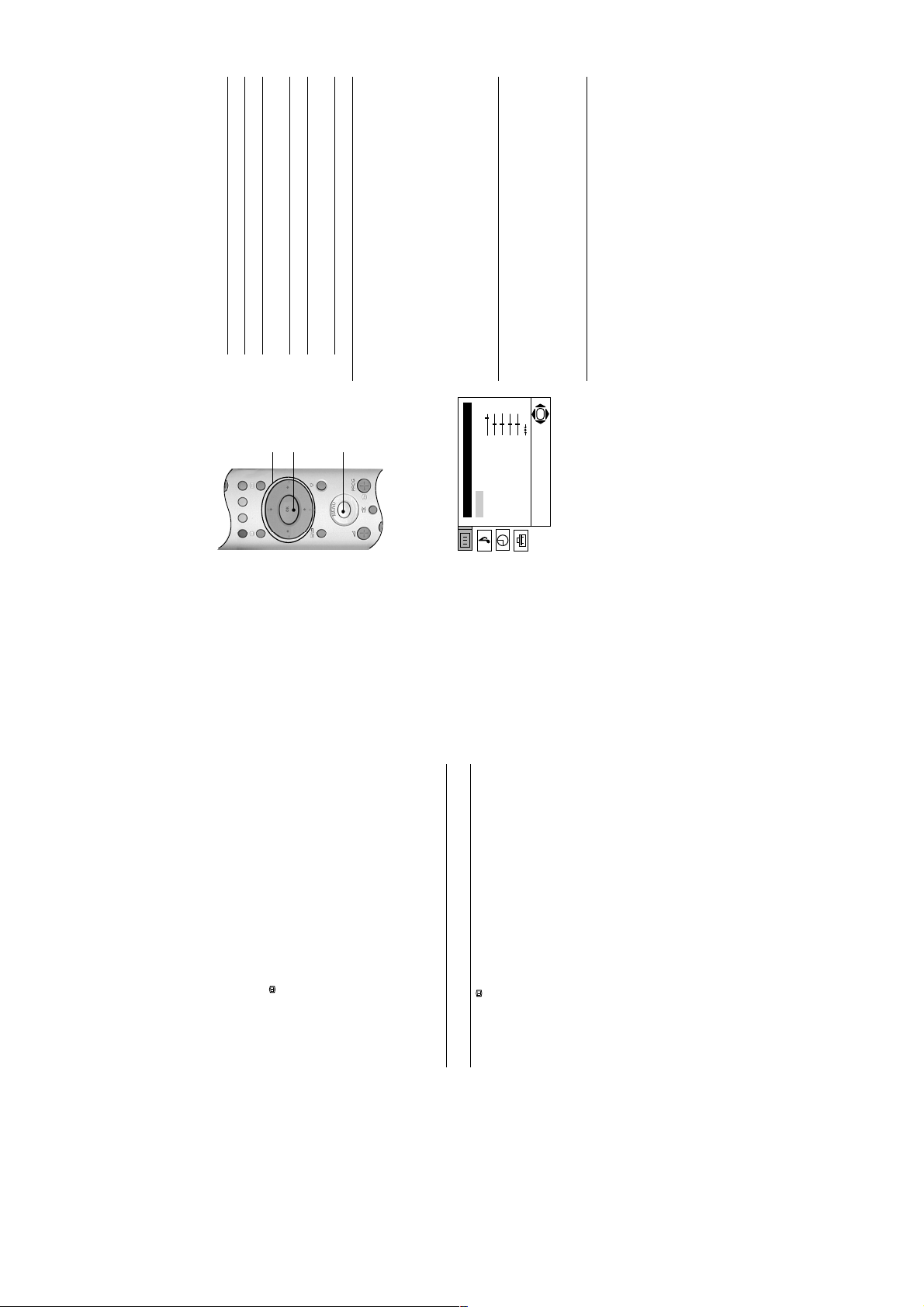
Use the following buttons to operate the TV menu system.
Using the TV menu
system
b button.
V, v, B or b buttons.
To Press
Access the TV menu system... MENU button.
Highlight an option... V or v buttons.
Enter the highlighted menu or
option...
1.
OK
V, v, B, and b
buttons
Store settings/changes... OK button.2.Press the MENU button to return to normal TV operation.
Return to the last menu or option... B button.
Alter the settings of a selected
option...
b button to set the level. Press the OK button to confirm.
Reset
This option resets all picture settings to the factory preset levels.
Mode
This option allows you to choose between three picture mode settings, ‘Live’,
‘Movie’ and ‘Personal’.
With the ‘Mode’ option highlighted, press the b button to adjust. Press the V or
v button to select the required mode. Press the OK button to confirm.
Contrast, Brightness, Colour, Sharpness, Hue
These options allow you to adjust the contrast, brightness, colour, sharpness
and hue.
‘Sharpness’ is not adjustable in digital mode. ‘Hue’ is only available when
viewing an NTSC colour signal, e.g. USA video tapes.
The individual menus are explained on the following pages.
button
MENU
button
Picture Adjustment
Mode: Personal
Contrast
Brightness
Colour
Sharpness
Hue
Picture Adjustment menu
The ‘Picture Adjustment’ menu.
With the required option highlighted, press the b button to adjust. Press the B or
OK
Reset
With the ‘Reset’ option highlighted, press the OK button to restore default picture
settings.
c) Manual timer REC***
Highlight ‘Manual timer REC’ and press OK if you wish to record a future
programme. The Manual Timer display appears.
***The ‘Manual timer REC’ feature only works if
you have connected your VCR to the AV2 socket
Press the V or v button to set the day of recording, then press the b
button to move to the start time. Repeat this procedure to set the start and
stop times and the channel number, then press the OK button to store
and return to the EPG menu.
Press the button to remove the EPG menu. Unless you have a
SMARTLINK VCR, you must now set the timer recording function of your
VCR to switch on and off to correspond with the programme you have
stored for recording.
Press the OK button to display the ‘Timers’ menu.
To cancel a recording
The Timer pop-up menu also has a ‘Timer list’ option. This list appears only after
you have set a programme to record or to wake up. If you highlight ‘Timer list’ and
i2/r on the rear of the TV. After you have
programmed a recording you can put the TV into
standby mode, but do not switch off completely
or the recording will be cancelled. If you put the
TV into standby mode, the standby indicator on
the front of the TV flashes green periodically to
remind you a recording has been programmed.
Press the V or v button to highlight the programme you wish to delete.2.Press the OK button to confirm deletion.3.Press the button when you wish to return to normal TV operation.
set for recording or wake up. To delete one of these programmes, proceed as
1.
follows:
press the OK button, a screen is displayed showing all the programmes you have
- 9 -
Page 10

(audio via o3 sockets, video via t3 socket)
A wide range of equipment can be connected to the TV through the front and rear
Connecting other
sockets. Most equipment can be connected to any of the TV sockets. Refer to the
instruction manual supplied with your equipment to determine the best TV socket
equipment to the TV
i2/r Scart S-Video, Audio/Video, Smartlink*.
i1/ Scart RGB, Audio/Video.
TV Sockets Socket type(s) Inputs supported
to use. This TV supports the following inputs:
o3 and t3 Phono (x3) Audio/Video.
*Smartlink is a direct link between the TV and a
compatible VCR or DVD recorder. Ensure that
your VCR/DVD recorder is connected to the
scart socket labelled i2/r, using a fully wired
21 pin scart lead. For more information on
Smartlink, refer to the instruction manual
supplied with your Smartlink VCR/DVD recorder.
If you have used a fully wired 21-pin scart lead to connect the VCR:
Viewing pictures from
If you have not used a fully wired 21-pin scart lead to connect the VCR:
Refer to ‘Viewing pictures from equipment connected to the rear sockets’, below.
a connected VCR
You will need to find the video channel:
Insert a pre-recorded tape into the VCR and press the ‘PLAY’ button.2.If you inserted a pre-recorded tape and pressed ‘PLAY’ during the
1.
autotune process, as instructed on page 6:
With the TV in analogue mode, press the PROG +/- buttons until the
picture from the pre-recorded tape is displayed on the TV screen.
In future, with the TV in analogue mode, press the Numbered buttons to
directly select the video channel.
If you wish to move your video channel, refer to the ‘Programme Sorting’
on page 23.
If you did not insert a pre-recorded tape and press ‘PLAY’ during the
autotune process, as instructed on page 6:
You will need to manually tune in the VCR signal (ideally to channel 0).
Insert a pre-recorded tape into the VCR and press the ‘PLAY’ button.
manual to manually tune in the VCR signal.
After manually tuning the VCR signal and with the TV in analogue mode,
press the Numbered buttons to directly select the video channel.
Refer to the ‘Manual Programme Preset menu’ section of this instruction
Switch on/press ‘PLAY’ on the connected equipment. The picture (if any)
1.
Viewing pictures from
equipment connected
from the equipment appears on the TV screen.
If the picture does not automatically appear press the / button
to the rear sockets
repeatedly until the picture is displayed on the TV screen.
Press the DIGITAL button or the a button to return to normal TV
operation.
2.
Viewing pictures from
from the equipment appears on the TV screen.
Press the / button repeatedly until the t3 symbol appears on the
TV screen.2.Switch on/press ‘PLAY’ on the connected equipment. The picture (if any)
1.
equipment connected
to the front sockets
Press the DIGITAL button or the a button to return to normal TV
operation.
3.
Auto Format
This TV can detect the type of screen format being transmitted by the
broadcaster (only if the specific signals are transmitted with the program). This
option allows the TV to automatically switch to the correct screen mode.
Detail Set Up menu
The ‘Detail Set Up’ menu.
With the ‘Auto Format’ option highlighted, press the b button to adjust. Press the
V or v button to select ‘On’ or ‘Off. Press the OK button to store.
Noise Reduction
On
Auto
A-TV00
Detail Set Up
Auto Format:
Noise Reduction:
AV2 Output:
the V or v button to select ‘Auto’ or ‘Off. Press the OK button to store.
Sometimes a weak signal can produce a snowy picture (called picture noise).
This option can help to reduce this effect.
With the ‘Noise Reduction’ option highlighted, press the b button to adjust. Press
Off
RGB Centring:
Picture Rotation:
Radio Mode:
r3 socket.
only available when the TV is receiving an RGB signal)
i2/r socket on the rear of the TV. Set the ‘AV2 Output’ option to ‘AV3 ’. Press
‘PLAY’ on the camcorder. The picture is sent through the AV2 socket to the VCR.
Change the channel on the VCR until the picture from the camcorder appears.
Press ‘RECORD’ on the VCR.
Connect a camcorder to the t3 sockets on the front of the TV and a VCR to the
AV3 Outputs signals from equipment connected to the t3 socket.
AV1 Outputs signals from equipment connected to the i1/ socket.
YC3 Outputs signals from equipment connected to the
A-TV Outputs an analogue TV broadcast.
D-TV Outputs a digital TV broadcast
can then record from equipment connected to other sockets of the TV.
AV2 Output
This option allows you to set a signal to be output through the socket labelled
i2/r on the rear of the TV. If you connect a VCR to the i2/r socket, you
z For example, to record from a camcorder to a video tape:
OK
With the ‘AV2 Output’ option highlighted, press the b button to adjust. Press the
V or v button to select ‘D-TV’, ‘AUTO’, ‘A-TV’, ‘YC3’, ‘AV3’ or ‘AV1’. Press the
OK button to confirm.
AUTO Outputs whatever is being viewed on the TV screen.
Setting Function
RGB Centring (
When viewing an RGB signal from equipment connected to the i1/ socket
(e.g. DVD player, PlayStation), the picture may need some adjusting. This option
allows you to adjust the horizontal picture position so that the picture is in the
middle of the TV screen.
With the ‘RGB Centring’ option highlighted, press the b button to adjust. Press
OK button to store.
Picture Rotation
the V or v button to adjust the fine tuning over a range of -10 to +10. Press the
Due to the Earth’s natural magnetism, the picture might look slanted. This option
OK button to store.
Radio Mode
allows you to cancel this effect.
When set to ‘Auto’, this feature is intended to automatically reduce the picture
With the ‘Picture Rotation’ option highlighted, press the b button to adjust. Press
the V or v button to adjust the fine tuning over a range of -5 to +5. Press the
V or v button to select ‘Auto’ or ‘Off’ then press the OK button to store. If set to
‘Auto’, the brightness and contrast levels will automatically reduce after 1
minute, Use only the 2 +/- volume buttons during this time, otherwise the
With the ‘Radio Mode’ option highlighted, press the b button to adjust. Press the
normal picture settings will be restored.
settings to an acceptable level when a digital radio service is being broadcast
from the TV.
- 10 -
Page 11

channels. Refer to the section
‘Manual Programme Preset’. Contact
a local installer to find out when
digital transmissions begin in your
area.
transmitter.
the TV (not through other
‘Colour’ and ‘Contrast’ settings.
TV I/1 button on the remote control.
• Plug in the TV.
• If the 1 indicator is lit, press the
• Press the ! button on the front of the
menu and adjust the ‘Brightness’,
TV.
• Check aerial connection.
• Tune in all available analogue
• Ensure aerial is correctly aligned to
equipment).
• Ensure aerial is plugged directly into
transmission details
• Upgrade to a higher gain aerial.
• Upgrade to a higher gain aerial.
• Contact the broadcaster for
qualified personnel.
Service Centre.
• Do not open the cabinet, refer to
• Contact your nearest
• Refer to the EPG section of this
on the remote control.
manual.
• If % is displayed, press the % button
• Set TV speakers to ‘On’ in the Detail
• Press the 2 + button on the remote
DVD player etc.)
menu and adjust the ‘Colour’ setting.
Adjustment menu.
control.
• TV in standby.
• Aerial disconnected.
• No digital transmissions in your area.
• Low picture settings. • Access the ‘Picture Adjustment’
• Weak signal.
• Unsuitable aerial.
• Channel used only for data (no
picture or sound).
Record’ (regular flash)
• Digital programme set for ’Timer
• TV speakers turned ‘Off’.
• Connected equipment switched on. • Switch off external equipment (VCR,
personnel or contact the UK Digital HelpLine on 0870 600 1717.
• If you continue to have these problems, have your TV serviced by qualified
• NEVER open the casing yourself.
Problem Cause Solution
Remote control does not work. • Batteries low. • Replace batteries.
Distorted picture when changing
No picture on any channel after digital
Troubleshooting
No picture, no sound. • Power off.
Here are some simple solutions to problems which may affect the picture and sound.
tuning.
Poor or no picture (screen is dark), good
sound.
Some channels are blank. • Channel not being transmitted.
Standby indicator flashing. • Fault (irregular flashing).
Good picture, no sound • Low or muted volume
No colour on colour programmes. • Low colour level settings. • Access the ‘Picture Adjustment’
programmes or selecting text.
standard) including audio/video input,
RGB input, TV audio/video output.
standard) including audio/video input,
S-VIDEO input, selectable audio/
video output.
RF In (DIGITAL)
RF In (ANALOGUE)
RF Out
Audio output - phono jacks.
PCMCIA (for future use only).
I/DVB-T
PAL
NTSC 3.58, 4.43 (only Video In)
MPEG-2 MP@ML
UHF: B21-B69
FD Trinitron WIDE Approx. 71cm (28inches)
Left/Right: 2x14W (music power), 2x7W (RMS)
97W
Approx. 790 x 515 x 525 mm
Approx. 43kg
i1/ 21-pin Euro connector (CENELEC
i2/r 21-pin Euro connector (CENELEC
MODEM MODEM jack (for future use only).
i Headphone jack - minijack stereo.
r3 S-Video input - 4 pin DIN
t3 Video input - phono jack.
o3 Audio input - phono jack.
RM-949 remote control (1)
IEC designated size AA (R06) battery (2)
RF Lead.
Design and specification are subject to change without notice.
TV System
Colour System
Channel Coverage
Picture Tube
Sound Output
Power Consumption
Dimensions (w x h x d)
Weight
Rear Terminals
Front Terminals
Supplied Accessories
Specifications
- 11 -
Page 12
2-1. Rear Cover Removal
SECTION 2 DISASSEMBLY
=>
<=
=>
=>
=>
<=
=>
=>
=>
Remove the rear cover fixing screws indicated and withdraw the rear cover from the Beznet.
2-2. Chassis Removal and Refitting
To remove lift the main bracket rear slightly and slide the
chassis away from the beznet. Ensure that the interconnecting
leads are released from their purse locks to prevent damage
being caused.
When refitting the chassis ensure that the main
bracket is located in the beznet guide slots before
sliding the chassis forwards. Refit the
interconnecting leads in their respective purse locks.
- 12 -
Page 13
2-3. A Board Removal [ Step 1 ] 2-4. A Board Removal [ Step 2 ]
Clip.
Screw.
Remove the 3 screws securing the PWB to the main bracket.
1 can be seen in the photo above and the other 2 are either
side of the FBT assembly.
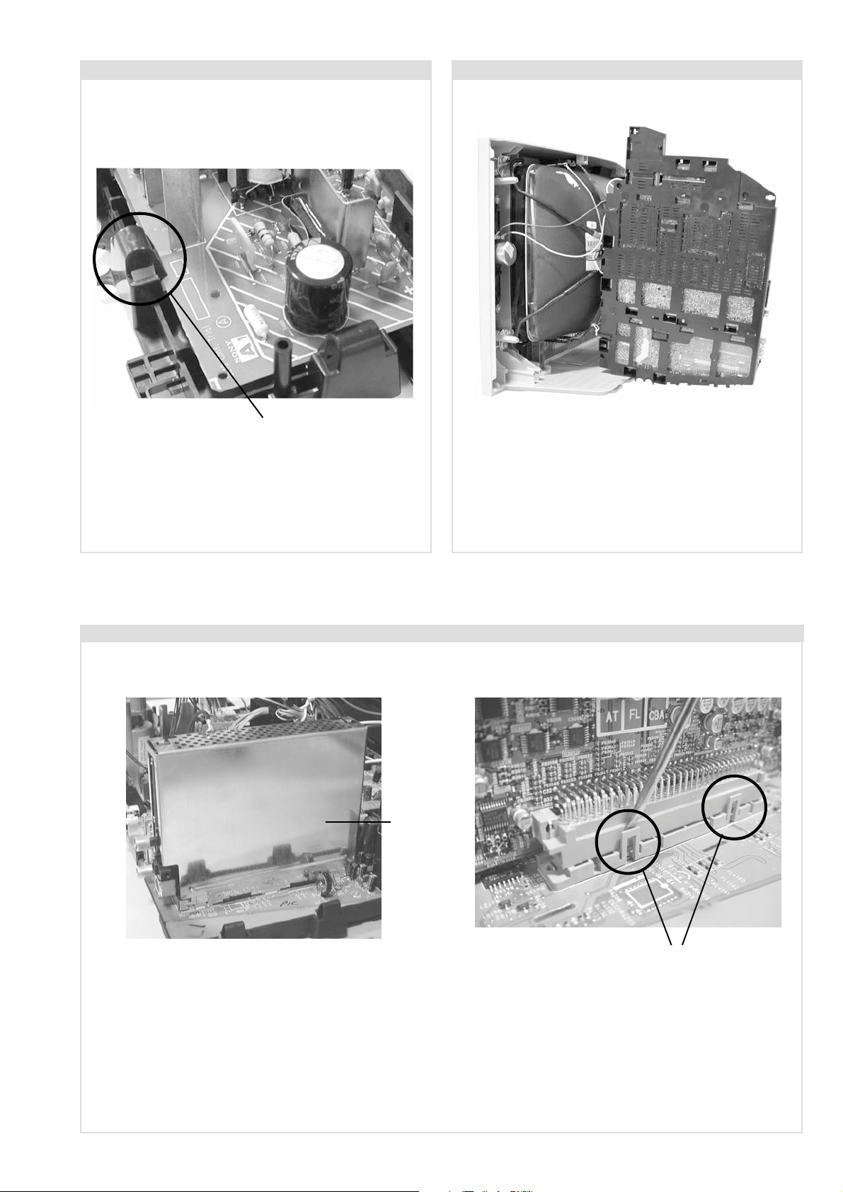
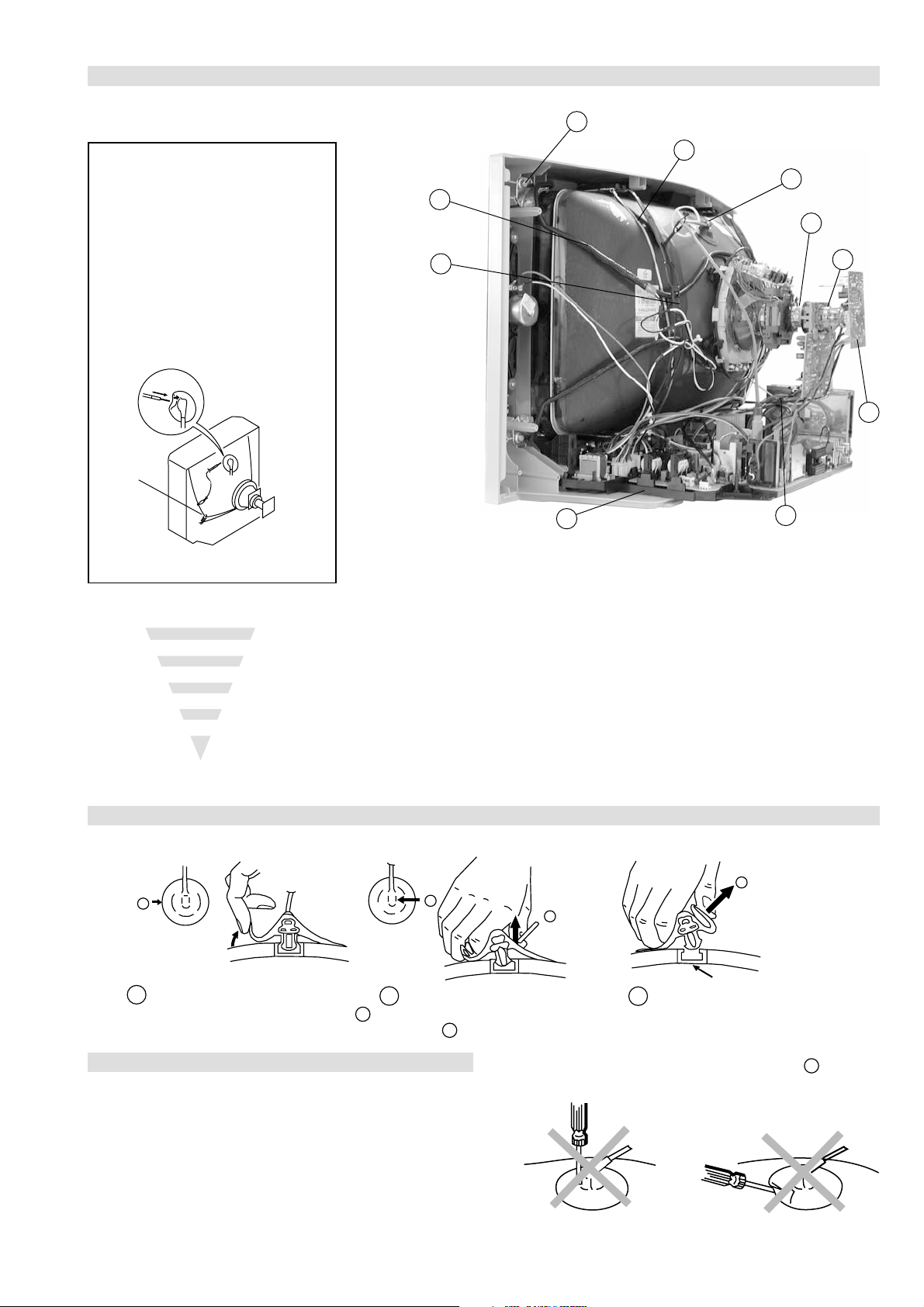
2-5. F3 Board Removal
Release the 5 securing clips located around the side of the
chassis and slide the PWB clear of the bracket.
Clip.
Release the 2 securing clips located along the side of the
chassis and slide the PWB clear of the bracket.
- 13 -
Page 14
2-6. A1 Board Removal 2-7. Service Position
Clip.
Release the 4 securing clips located around the side of the
chassis and slide the PWB clear of the bracket.
2-8. N Board Removal
Position the chassis as indicated to access the solder side
of the PWB’s. To gain access to the A Board follow the
instructions on page 16. [Removal and Replacement of the
main bracket bottom plates ].
Shield
case
Clips
Remove the shield case by pulling vertically until it is clear of the N Board. Release the N board socket retaining clips, circled, by
gently prising them with a screwdriver and carefully lift the N Board vertically.
- 14 -
Page 15
2-9. Picture Tube Removal
10
WARNING:
BEFORE REMOVING
THE ANODE CAP
High voltage remains in the CRT even
after the power is disconnected. To
avoid electric shock, discharge CRT
before attempting to remove the anode
cap. Short between anode and CRT
coated earth ground strap.
Coated Earth
Ground Strap
9
8
7
4
1. Discharge the anode of the CRT and remove the anode cap.
2. Unplug all interconnecting leads from the Deflection yoke, neck
assy, degaussing coils and CRT grounding strap.
3. Remove the C Board from the CRT.
4. Remove the chassis assembly.
5. Loosen the Neck assembly fixing screw and remove.
6. Loosen the Deflection yoke fixing screw and remove.
7. Place the set with the CRT face down on a cushion and remove
the Degaussing Coil holders.
8. Remove the Degaussing Coils.
9. Remove the CRT grounding strap and spring tensioners.
10. Unscrew the four CRT fixing screws [ located on each CRT
corner ] and remove the CRT.
[Take care not to handle the CRT by the neck.]
1
6
5
3
2
Removal of the Anode-Cap
* REMOVING PROCEDURES.
a
1
Turn up one side of the rubber cap in
the direction indicated by the arrow a
b
2 Using a thumb pull up the rubber cap
firmly in the direction indicated by the
arrow b
How to handle the Anode-Cap
1. To prevent damaging the surface of the anode-cap do not use
sharp materials.
2. Do not apply too great a pressure on the rubber, as this may cause
damage to the anode connector.
3. A metal fitting called a shatter hook terminal is fitted inside the
rubber cap.
4. Do not turn the rubber foot over excessively, this may cause
damage if the shatter hook sticks out.
c
b
Anode button
3 When one side of the rubber cap is
separated from the anode button, the
anode-cap can be removed by turning
up the rubber cap and pulling it up in
the direction of the arrow c
- 15 -
Page 16

For safety reasons, on no account should the plates be re-
moved and not refitted after servicing.
(2) REFITTING THE PLATES
Because the plates differ in size it is important that the correct plates are refitted in their original
location.
Please note that the plates need to be rotated 180 degrees from their cut position to allow the tabs to
be fitted into their catch positions.
Catch
Ta b
REMOVAL AND REPLACEMENT OF THE MAIN-BRACKET
BOTTOM PLATES.
Only remove the necessary plate to gain access to the printed wiring board.
In the event of servicing being required to the solder side of the A Board printed wiring board, the
bottom plates fitted to the main chassis bracket require to be removed.
This is performed by cutting the gates with a sharp wire cutter at the locations indicated by the
arrows.
(1) REMOVING THE PLATES
Note : There are 2 plates fitted to the main bracket.
- 16 -
Page 17
SECTION 3 SET-UP ADJUSTMENTS
• When complete readjustment is necessary or a new picture
tube is installed, carry out the following adjustments.
• Unless there are specific instructions to the contrary, carry
out these adjustments with the rated power supply.
• Unless there are specific instructions to the contrary, set the
controls and switches to the following settings :
Contrast .................... 80% [or remote control normal]
Brightness ................... 50%
Preparation:
1. In order to reduce the influence of geomagnetism on the
set’s picture tube, face it in an easterly or westerly direction.
2. Switch on the set’s power and degauss with the degausser.
3-1. Beam Landing
1. Input an all white signal from the pattern generator. Set the
Contrast and Brightness to normal.
2. Set the pattern generator raster signal to Red.
3. Move the deflection yoke forward and adjust with the
purity control so that the Red is at the centre and the Blue
and Green take up equally sized areas on each side of the
screen. [See Fig.3-1 - 3-3].
4. Move the deflection yoke backwards and adjust so that the
entire screen becomes Red. [See Fig.3-1]
5. Switch the raster signal to Blue, then to Green and verify
the condition.
6. When the position of the deflection yoke has been
determined, fasten the deflection yoke with the screws.
7. If the beam does not land correctly in all the corners, use a
magnet to correct it. [See Fig.3-4]
Carry out the adjustments in the following order :
3-1. Beam Landing.
3-2. Convergence.
3-3. Focus.
3-4. White Balance.
Note : Test equipment required.
1. Color bar/pattern generator.
2. Degausser.
3. Oscilloscope.
4. Digital multimeter.
Fig. 3-2.
Purity
Fig. 3-3.
GREEN
RED
BLUE
Disk magnets or
rotatable disk
Purity control corrects
this area
magnets correct
these areas (a-d)
Fig. 3-1.
Caution :
High voltages are present on the Deflection yoke terminals
- take care when handling the Deflection yoke whilst carrying
out adjustments.
- 17 -
Fig.3-4
ab
c
Deflection yoke positioning
corrects these areas
Disk Magnets
d
Page 18
GBR
GBR
GBR
G
B
R
GBR
G
B
R
3-2. Convergence
B
G
R
a
b
R
G
B
b
a
Preparation:
4. If the V.STAT magnet is moved in the direction of the (a)
and (b) arrows, the Red, Green and Blue points move as
indicated below.
• Before starting this adjustment, adjust the focus, horizontal
size and vertical size.
• Minimize the Brightness setting.
• Input a dot pattern from the pattern generator.
Horizontal and Vertical Static Convergence
Center dot
R
G
B
H STAT
convergence
control
R
G
B
V.STAT Vertical Static Magnet
C Board
RV702 (H STAT)
H STAT Convergence
(on mount side)
a
b
a
a
b
a
b
B
G
R
R
R
b
B
G
R
a
B
G
b
B
G
Fig.3-5
1. [Moving horizontally], adjust the H.STAT control so that
the Red, Green and Blue points are on top of each other at
the centre of the screen.
Operation of the BMC (Hexapole) magnet.
2. [Moving vertically], adjust the V.STAT magnet so that the
Red, Green and Blue points are on top of each other at the
centre of the screen.
3. If the H.STAT variable resistor is unable to bring the Red,
Green and Blue points together at the centre of the screen,
adjust the horizontal convergence with the H.STAT variable
resistor and the V.STAT magnet in the manner indicated
below.
[In this case, the H.STAT variable resistor and the V.STAT
magnet influence each other].
• Tilt the V.STAT magnet and adjust the static convergence by
opening or closing the V.STAT magnet.
The movement of the magnets interact with each other and so
the respective dot position should be monitored while carrying
out this adjustment.
Use the H.STAT VR to adjust the Red, Green and Blue dots so
that they coincide at the centre of the screen
(by moving the dots in the horizontal direction).
- 18 -
Page 19
+++
TLV VR 28"
Deflection Yoke
+
++
TLV VR 32"
Deflection Yoke
Geometry Adjustment.
a
b
d
Permalloy Assy
c
Install the permalloy assembly
for the area that needs correcting.
X-4387-214-1
Convergence adjustment with permalloy
APH circuit
harness
YCH Adjustment
Preparation:
Before starting this adjustment, adjust the horizontal and
vertical static convergence.
1. Remove the deflection yoke spacer.
2. Tilt the deflection yoke as indicated in the figure below and
optimise the geometry.
Tilting the DY Up and Down a small amount will balance
the upper and lower pin adjustment.
3. Re-install the deflection yoke spacers. Ensure 4 DY spacers are
reinserted
Tilt Direction
YCH VR 28"
Deflection Yoke
YCH VR 32"
+
+++
++
Deflection Yoke
TLV Adjustment
Screen Corner Convergence
If you are unable to adjust the corner convergence properly,
this can be corrected with the use of permalloy magnets.
a
a-d: screen-corner
convergence defect
b
4. The H-Trap and T-B Pin may not achieve a good level due
to a small tilt allowance on the square DY. Keep the DY in
a straight position and adjust H-Trap pot (See diagram for
HTIL Adjustment) and Y-Mg for T-B Pin, as below.
HTIL Adjustment
Deflection Yoke
H-Trap YCH TLV
TLH Piece
28” 32”
HTIL correction can be performed by adding
correction assembly to the Deflection yoke.
Deflection Yoke
YCH
TLV
H-Trap
TLH Piece
one TLH
c
d
• APH Convergence parameter is electrically controlled. For this
reason a TLH piece may not be required.
(APH = Red vertical lines on the edge of the screen).
- 19 -
Page 20

Layout of each control
V.STAT
Purity
BMC (Hexapole)
3-3. Focus Adjustment
1. Receive a television broadcast signal.
2. Normalize the picture setting.
3. Adjust the focus control located on the flyback transformer
to obtain the best focus at the centre of the screen.
Bring only the centre area of the screen into focus, the
magenta-ring appears on the screen. In this case, adjust the
focus to optimize the screen uniformly.
3-4. Screen (G2), White Balance
[Adjustment in the service mode using the remote
commander]
G2 adjustment
1. Input a dot signal from the pattern generator.
2. Set the Picture, Brightness and Colour to minimum.
3. Apply 165V DC from an external power supply to the R, G
and B cathodes of the CRT.
4. Whilst watching the picture, adjust the G2 control [SCREEN]
located on the flyback transformer to the point just before the
flyback return lines disappear.
White balance adjustment for TV mode
1. Input an all-white signal from the pattern generator.
2. Set the TV set or operation in Service Mode.
[ See Page 21 ].
3. Select ‘Service’ from the on screen menu display and press
‘Right Arrow’.
4. The ‘Service’ menu will appear on the screen.[See Page 21]
5. Set the ‘Subcont’ to MAX.
6. Set the ‘R-Drive’ to 50.
7. Adjust the ‘G-Drive’ and the ‘B-Drive’ so that the white
balance becomes optimum.
8. Press the ‘OK’ button to write the data for each item.
9. Set the ‘Subcont’ to MIN.
10. Adjust the ‘Cutoff Br.’ with the left and right buttons on the
remote commander so that the white balance becomes optimum.
11. Press the ‘OK’ button to write the data.
Focus
Screen
- 20 -
Page 21

SECTION 4 CIRCUIT ADJUSTMENTS
4-1. Electrical Adjustments
Service adjustments to this model can be performed using the
supplied remote Commander RM-949.
How to enter into the Service Mode
1. Turn on the main power switch and enter into the stand-by mode.
2. Press the following sequence of buttons on the Remote
Commander.
i+
(ON SCREEN (DIGIT 5) (VOLUME +) (TV)
DISPLAY)
5
‘TT—’ will appear in the upper right corner of the screen.
Other status information will also be displayed.
3. Press ‘MENU’ on the remote commander to obtain the following
menu on the screen.
ecivreS
ngiseD
sutatS
dnuoS
4. Move to the corresponding adjustment item using the
up or down arrow buttons on the Remote Commander.
5. Press the right arrow button to enter into the required menu item.
6. Press the ‘Menu’ button on the Remote Commander to quit the
Service Mode when all adjustments have been completed.
Note :
• After carrying out the service adjustments, to prevent the
customer accessing the ‘Service Menu’ switch the TV set OFF
and then ON.
+
yrtemoeG
tsujdAFI
unemrorrE
90.1vtxeND2-EF
h96h10atadyrotcaF
G1143PSM:eciveDPSM
ECIVRES
R-tesffO
G-tesffO
evirD-R
evirD-G
evirD-B
qerF-kaeP
yaleD-amuL
0CS
kaeP-etihW
tnocbuS
thgirbuS
locbuS
prahsbuS
.rBffotuC
DSOrB
TXTrB
YRTEMOEG
ytiraeniL-V
llorcS-V
klBH-tfeL
klBH-thgiR
elgnA-V
woB-V
ertneC-H
eziS-H
pmA-niP
niP-renroC-U
niP-renroC-L
esahPniP
epolS-V
eziS-V
noitcerroC-S
ertneC-V
mooZ-V
atnegaM
tliT-YD
)36,0(
)36,0(
)36,0(
)36,0(
)36,0(
)3,0(
)51,0(
)3,0(
)51,0(
)51,0(
)36,0(
)36,0(
)36,0(
)36,0(
)51,0(
)51,0(
)36,0(
)36,0(
)51,0(
)51,0(
)36,0(
)36,0(
)36,0(
)36,0(
)36,0(
)36,0(
)36,0(
)36,0(
)36,0(
)36,0(
)36,0(
)36,0(
)36,0(
)36,0(
)83,52(
jdA
jdA
13
jdA
jdA
0
8
3
51
8
03
jdA
52
13
01
7
jdA
23
01
7
jdA
jdA
jdA
jdA
jdA
jdA
jdA
jdA
04
jdA
jdA
jdA
72
13
13
UNEMRORRE
20E
30E
40E
50E
60E
70E
80E
90E
01E
11E
21E
31E
41E
GNIKROW
EMIT
SRUOH
SETUNIM
PCO
A/NPVO
CNYSV
RKI
CII
MVN
ELGNUJ
RENUT
PDNUOS
V8
AMME
XETROP
CTR
)552,0(
0
)552,0(
0
)552,0(
0
)552,0(
0
)552,0(
0
)552,0(
0
)552,0(
0
)552,0(
0
)552,0(
0
)552,0(
0
)552,0(
0
)552,0(
0
)552,0(
0
7
22
TSUJDAFI
tsujdACGA
etumotuA
niaGoiduA
gnitaGL
)51+,61-(0+
1
0
1
- 21 -
Page 22

Deflection System Adjustment
Sub Brightness Adjustment
1. Set the TV set or operation in Service Mode [ See Page 21 ]
and enter into the ‘Geometry’ service menu.
2. Select and adjust each item in order to obtain the optimum image.
V SIZE
V LIN
AFC BOW
V POSITION
H POSITION
H SIZE
PIN AMP
TRAPEZIUM
UP CORNER PIN
1. Input a Monoscope pattern.
2. Set the TV set or operation in Service Mode. [ See Page 21 ].
3. Select ‘Service’ from the on screen menu display and press
‘Right Arrow’.
4. The ‘Service’ menu will appear on the screen. [See Page 21].
5. Adjust the ‘Sub-Brightness’ data so that there is barely a
difference between the 0 IRE and 10 IRE signal levels.
Sub Contrast Adjustment
1. Input a video signal that contains a small 100% white area on a
black background.
2. Connect an digital voltmeter to Pin 10 of J701 [C Board].
3. Set the TV set or operation in Service Mode.
[ See Page 21 ].
4. Select ‘Service’ from the on screen menu display and press
‘Right Arrow’.
5. The ‘Service’ menu will appear on the screen.[See Page 21]
6. Adjust the Sub-Contrast to obtain a voltage of 105 +/- 5V.
Sub Colour Adjustment
1. Receive a PAL colour bar signal.
2. Connect an oscilloscope to Pin 5 of CN003 [A Board].
3. Set the TV set for operation in Service Mode.
[ See Page 21 ].
4. Select ‘Service’ from the on screen menu display and press
‘Right Arrow’.
5. The ‘Service’ menu will appear on the screen.[See Page 21]
6. Adjust the ‘Sub Colour’ sothat the Cyan, Magenta and Blue
colour bars are of equal levels as indicated below.
AFC ANGLE
LO CORNER PIN
B-Out Waveform
YRTEMOEG
ytiraeniL-V
llorcS-V
klBH-tfeL
klBH-thgiR
elgnA-V
woB-V
ertneC-H
eziS-H
pmA-niP
niP-renroC-U
niP-renroC-L
esahPniP
epolS-V
eziS-V
noitcerroC-S
ertneC-V
mooZ-V
atnegaM
tliT-YD
)36,0(
)36,0(
)51,0(
)51,0(
)36,0(
)36,0(
)36,0(
)36,0(
)36,0(
)36,0(
)36,0(
)36,0(
)36,0(
)36,0(
)36,0(
)36,0(
)36,0(
)36,0(
)83,52(
jdA
23
01
7
jdA
jdA
jdA
jdA
jdA
jdA
jdA
jdA
04
jdA
jdA
jdA
72
13
13
Same Level
- 22 -
Page 23

4-2. TEST MODE 2:
Test Mode 2 is available by programming the TV set for operation in Service Mode [ As shown on Page 21 ], OSD ‘TT’ appears. The functions
described below are available by selecting the two numbers. To release the ‘Test mode 2’, press 00, 10, 20 ... twice or switch the TV set into
Stand-by mode. In ‘TT Menu’ mode, it is possible to remove the Menu from the screen by pressing the Speaker OFF button once. Pressing the
Speaker OFF button a second time will cause the Menu to reappear. The function is kept even when the menu is not displayed on screen.
00
10
20
30
40
50
60
70
80
11
21
31
41
51
61
91
12
22
32
42
52
62
72
82
13
63
14
34
44
54
64
84
94
35
55
95
86
37
47
87
97
78
99
ffoedom'TT'
mumixamerutciP
muminimerutciP
%53otemuloVenohpdaeh/rekaepsteS
%05otemuloVenohpdaeh/rekaepsteS
%56otemuloVenohpdaeh/rekaepsteS
%08otemuloVenohpdaeh/rekaepsteS
edomgniegA
noitidnoCgnippihS
tnemtsujdaerutcipbuS
tnemtsujdaruolocbuS
tnemtsujdassenthgirBbuS
tnemtsujdanoitisoPHtxeT
tseTlioCnoitatoR
%05levelerutciP
elbasiD/elbanEedoMyrotcaF
RKEDAnoitanitseD
LBnoitanitseD
RKEDAnoitanitseD
UnoitanitseD
RKEDAnoitanitseD
LBnoitanitseD
RKEDAnoitanitseD
RKEDAnoitanitseD
elbasiD/elbanEffotuhSotuA
tsetNO/FFO)MV(noitaludoMyticoleV
MVNesilaitini-eR
dnuosAlauDtceleS
dnuosBlauDtceleS
dnuosonoMtceleS
dnuosoeretStceleS
nigrivnonsaMVNteS
nigrivsaMVNteS
elbasiD/elbanEnoitaludomrevOMF
)SPLA/YNOS(noitcelesrenuT
stracS2roPIP+stracS3ledoMtceleS
)melborpN(erusaemretnuoc62XelbasiD/elbanE
)47.6/5.6(metsys2K/DnotiewZelbanE
)47.5/5.6(metsys3K/DnotiewZelbanE
thgirllufecnalaB
tfelllufecnalaB
tsetsyeklacoL
unememiTgnikroWdnarorrEyalpsiD
- 23 -
Page 24

5-1. BLOCK DIAGRAMS (1)
A1 ( )
DIGITAL FRONT
END PROCESSING
CN4101
TO
N BOARD
IC4104
A/D VIDEO
SWITCH
12
SWITCH
Q4124
5
2
RIGHT
TO
B1 BO ARD
CN8401
6
SDA-TV X
SWITCH
Q4115
SWITCH
Q4117
INVERTER
Q4118
10
INVERTER
Q4119
11
INVERTER
Q4120
15
4
14
SWITCH
Q4107
3
4
5
Y
Z
14
15
5
62
1
X4101
XTAL
SCL-TV
SWITCH
Q4113
SWITCH
Q4112
SDA-TV
SCL-TV
CVBS-A/D
IC4102
RTC
C (Z)
B (Y)
A (X)
SCL (TV)
SDA (TV)
Y0
Z0
A (X)
D CVBS
RY
GC
LEFT MPEG
RIGHT MPEGRIGHT-DIGITAL
LEFT-DIGITAL
C-DIGITAL
Y-DIGITAL/CVBS-A
10
CN4104
11
15
5
6
1
2
IC4105
PORT EXPANDER
A22
A7
A6
A5
A4
A3
C1
B1
A1
LEFT
MUTE
FBLK
CVBS
B
G/C
R/Y
SCL (TV)
SDA (TV)
PTEN
FE RESET
FE LOCK
SCL (N)
SDA (N)
N RESET
PT CLK
PT SYNC
TS6
TS7
TS4
TS5
TS2
TS3
TS0
TS1
B22
A24
A25
B25
A26
B26
C26
A28
B28
A29
B29
A30
B30
A31
B31
A32
B32
2
1
3
4
GREEN/U
RED/Y
BLUE/V
FBLK
CN4103
52
53
5
6
7
8
11
12
13
14
15
16
17
18
SCL-N3V3
PT CLK
PT EN
PT SYNC
TS (0)
TS (1)
TP ERROR
TS (2)
TS (3)
AC IN
2
1
CN4601
IC4601
AC IN
TO
A BOARD (2/2)
CN607
2
3
CN4602
1
2
TO
A BOARD (1/2)
CN642
UNREG 5V
EPG STBY
IC4608
COMPARATOR
7
SWITCH
Q4601
RY4601
BRIDGE
RECTIFIER
D4601
8
1
2
3
9
4
1
8
I
IC4604
REGULATOR
O
+5V
I O
IC4611
5V REGULATOR
5VA
5VD
4
IC4607
3.3V REGULATOR
2
3.3V
IC4602
PHOTOCOUPLER
C
IC4603
ERROR AMPLIFIER
I O
1
9V
D4603
T4601
TO
A BOARD (1/2)
CN301
SWITCH
Q4106
3
1
SWITCHES
Q4114
Q4116
Z1
Y1
13
8
7
AGC
AM
QSS
SCL
SDA
AGC
FM/AM
QSS
VIDEO
TUNER
TU4102
TUNER
TU4800
16
15
14
1
5
4
IC4606
REGULATOR
IC4300
SDA-N3V3
TS (4)
TS (5)
TS (6)
TS (7)
57
58
59
53
54
IF AGC
SDA
SCL
DIGITAL IF
DIGITAL IF
1
10
9
5
2
SWITCH
Q4608
AMP
Q4605
Q4606
Q4607
4
SWITCH
Q4604
N RESET
IC4610
DIGITALLY
CONTROLLED
ANALOGUE SWITCH
DCVBS
2VPP-AORD-CVBS
AORD-CVBS
CN4603
TO A BOARD (1/2)
CN302
1
3
AV2 SCART
AV2 UOC
O
15
9
14
117
TO
A BOARD (1/2)
CN1200
WOOFER MUTE
TO
A BOARD (1/2)
CN406
TO
A BOARD (1/2)
CN405
TO
A BOARD (2/2)
CN606
CN3601
AC IN
AC IN
LIGHTNING
1
2
F3 ( )
CN8401
Y IN
1
TO
A1 BO ARD
CN4103
2 U IN
3 V IN
4 FBLK IN
B1 ( )
R9
L
Y/CVBS
KEY
SIRCS
LED76
AC OUT
SWITCHES
S900 - S905
IC7150
SIRCS RECEIVER
2
SWITCH
Q7150
SWITCH
Q7151
S7601
POWER
INPUT, SIRCS RECEIVER
CN908
1
2
R IN
3
R OUT
5
L OUT
6
L IN
CN906
6
4
1
CN7150
CN7601
15AC OUT
H9 ( )
FUSE
F3601
AC INPUT, FUSE
BUFFER AMP
Q8402, Q8405
BUFFER AMP
Q8403, Q8406
BUFFER AMP
Q8404, Q8407
SWITCH
Q8401
Y, U, V SWITCHING
Y/C AND FRONT AV INPUT
Y/C, FRONT AV
LED AND SIRCS RESPONSE
RG
LINE FILTER
43
D7150
AC INPUT
T3602
21
IC8401
YUV SWITCH
2
Y0
5
Z0
12
X0
9
C
10
B
11
A
T3601
LINE FILTER
43
14
X
4
Z
15
Y
1
Y1
3
Z1
13
X1
21
AC OUT
AC OUT12
V OUT 1
U OUT
Y OUT
Y IN
U IN
V IN
AC IN
AC IN
V
L
R
CN8402
2
3
5
6
7
2
1
CN3603
J901
CN7602
TO
H9 BOARD
CN7602
TO
A BOARD (1/2)
CN002
TO
F3 BOARD
CN3603
J900
HEADPHONES
- 24 -
Page 25

1
CN002
J401(1/2)
63
IC001
MICRO, VIDEO
PROCESSOR, ROM, AUDIO,
VIDEO SWITCH
XTAL OUT
RED
AUDIO 3/V OUT
TO SPEAKERS
A 1/2 ( )
POWER SUPPLY,
DEFLECTION, VIDEO, AUDIO
5
2
CN1201
64
XTAL IN
+
-
IC1201
STEREO AMP WITH MUTE
MUTE
1
IN W
10 14
OUT/L
68
IC401 AV LINK
69
R0
56
B10
7
6
5
2
G0
57
B0
58
IK
55
GREEN
BLUE
IK
EWD 17
VD-
18
VD+
19
ABL
54
TO
C BOARD
CN703
CN003
J401 (2/2)
SDA
6
SCL
5
7
WP
72
SCL
71
SDA
28
CVBS2/
CVBSY2
2KEY
3AGC
53 B2/UIN
1 MODE1
80 MODE2
52 G2/YIN
51 R2/VIN
38 -/C4
50 INSSW2
32 CVBS1
37 -/CVBS4Y4
8
11
7
29
15
16
41
36
20
BLUE
MODE
MODE
GREEN
RED
C2 IN
BLK
V IN 1
Y/V IN 2
BUFFER
Q401, Q411
A19
MUTE SW
Q212
CN406
STBY
70
41
77
TO A 2/2
23
FREE 1 MAGENTA
VD+
V-PULSE
MAGENTA
CN510
TO
VM BO ARD
CN1701
VM OUT
AVL OUT
AVL IN
34
5
INR
12
CVBS3
28
29
46
47
36
33
53
50
37
34
52
49
1
22
2
23
3
24
6
27
R OUT 1
R OUT 2
R IN 1
R IN 2
L OUT 1
L OUT 2
L IN 1
L IN 2
SC1 OUT R
SC2 OUT R
SC1 IN R
SC2 IN R
SC1 OUT L
SC2 OUT L
SC1 IN L
SC2 IN L
DACMR
DACML
SC3 IN L
SC3 IN R
73EPG STBY
3
CN642
EPG STBY
TO
A1 BO ARD
CN4602
9
6
4
1
KEY
CVBS/Y
R
L
TO
H9 BOARD
CN906
10
9
55
58
44
43
SCL
SDA
ANA-IN1+
MONO IN
AMPLIFIER
Q202, Q203
SC4-IN-R
SC4-IN-L
IC201
MSP3411G
SOUND PROCESSOR
5
15
11
10
7
8
2
1
YD/CVBS
CN301
CVBS/AD
SCL
SDA
QSS
AM
RIGHT D
RIGHT L
TO
A1 BO ARD
CN4104
67
6
5
2
3
4
7
6
2
3
5
6
7
45
46
47
48
49
V OUT
U OUT
Y OUT
Y IN
V IN
U IN
TO
B1 BO ARD
CN8402
AUDIO 1 U IN
Y IN
Y OUT
U OUT
CN405
LED
SIRCS
KEY
TO
H9 BOARD
CN7150
SERVICE
CN001
75
6
5
2
3
+
-
1
7
19
76
FBISO
SSCP 7
10
9
BUFFER AMP
Q1233
BUFFER AMP
Q1232
J404
R OUT
L OUT
3
6
L IN
R IN
1
4
CN1200
R AUDIO
L AUDIO
TO
H9 BOARD
CN908
OUT/R
X001
LOW B
LED
SIRCS
NVM WP
FREE 1 DEF SW
IC004
4HP PLUGGED
HP
PLUGGED
1
4
65
RESET
CS
SCL
SDA
AGC
31
6
IN/INL
SWITCH
Q1230
SWITCH
Q1231
DACM-SUB
CN302
1
3
TO
A1 BO ARD
CN4603
AV2 SCART
FROM U OC
30
AMPLIFIER
Q409
40
AV2 SCART
CVBS 0
5-1. BLOCK DIAGRAMS (2)
TO C BOARD
CN1802
TO A BOARD (1/2)
CN510
SMART
TO
A BOARD (2/2)
CN1902
CN1701
SWITCH
CN512
CN703
TO
A BOARD
CN003
10 MAGENTA
CN1802
TO
VM BO ARD
CN1902
3 V PULSE
V PULSE
9
7 NS CORRECT
VM ( )
CN8801
6
2
HDY-
8
6
5
7
2
1
3
R, G, B OUT
C ( )
G IN
B IN
R IN
IK
NS CORRECT
V-PULSE
AMP
Q1901
VELOCITY
MODULATION
SWITCH
Q8802
Q8803
OPERATIONAL
COMPARATOR
3
5
IC1902
AMP
IC1901
+8V
13
2
IC8801
SMART MODE
D8802
DEFLECTION
D2 ( )
IC701
R.G.B. DRIVE
1
2
3
5
1
2
3
IC1801
ROTATION AMP
AMP
Q1801, Q1802,
Q1803
72
7
8
BUFFER
Q1906
AMP
Q1840
Q1841
SWITCH
Q1902
G OUT
9
B OUT
8
R OUT
7
7
6
4
+200V
SMART MODE
DEFLECTION
ROT (-)
ROT (+)
AMPLIFIER
Q1907
AMP
Q1903
MOSFET
SWITCH
Q8801
CN707
1H2
G2
3
CN706
1
J701
6
3
9
8
10
CN1801
3
1
T1901
TO A BOARD (2/2)
CN508
TO A BOARD (2/2)
T511 FBT
TO ROTATION COIL
CY- 1
CY+
QP-
QP+
DF 1
PICTURE TUBE
CN1901
TO DY
3
CN1718
1
2
5
6
CN1809
TO A BOARD (2/2)
NECK ASSY
CN509
- 25 -
Page 26

5-1. BLOCK DIAGRAMS (3)
TO
H9 BOARD
CN7601
FOR CHECK
DGC
TO PFC
TO A1 BOARD
CN4601
CN606
CN603
CN602
CN605
CN607
1
2
1
2
1
2
3
1
1
2
AC IN
AC IN
DGC CHECK
DGC CHECK
DGC
DGC
PFC
PFC3
AC OUT
AC OUT
STBY
SWITCH MODE
POWER SUPPLY
4
5
RELAY
SWITCH
Q601
IC609
IC501
HP
PROTECT
VERTICAL DEFLEC TION
VD+
7
IN
VP
3
BOOST
VD-
1
REF
PIN CORRECTION
EW
65+
3
2
+B
BOOSTER
IC531
-
+
-
OUT
CN501
6
5
SW532
PIN O UT
7
Q532
1
T511
FBT
1
4
2
5
6
HV
G2
FV
13
12
ABL
11
10
9
8
7
V- DY+
V- DY-
H- DY-
H- DY-
H- DY+
H- DY+
H- DY-
SMART
SW
DF
D513
+15V RECT
D514
-15V RECT
H1
200V
5
4
3
2
1
CN512
8
6
2
CN509
1
CN508
1
3
TO DY
TO D2 BOARD
CN8801
TO PICTURE
TUBE
TO C BOARD
CN706
TO VM BOARD
CN1809
TO C BOARD
CN707
PH601
ISOLATOR
4
MAIN RECT
7
8
5
D601
IC601
POWER SUPPLY
2
FB
1
VSENSE
CT
3
4
RT
6
TIMER
7
SS
9
OCP
8
VC1
D632
3
18
VD
16
VGCH
VG(G)
I
12
15
VS
IC608
3.3V REG
Q607
O
Q606
+3.3V
D608
9
8
7
6
RELAY
RY601
REG
D614
1
T602
2
1
4
3
T603
(PIT)
1
2
10
11
17
15
16
18
12
LOW B
IC602
D619
D618
D638
ERROR AMP
1
QCP
DETECT
Q602, Q603
HD
2
AUDIO VCC
LOW B
H-DRIVE
Q535
T531
HDT
H-OUT
Q533
RECT
D625
3
1
2
3
RECT
D625
TO A 1/2
POWER SUPPLY,
A 2/2 ( )
DEFLECTION, VIDEO, AUDIO
ABL
- 26 -
Page 27

5-2. CIRCUIT BOARD LOCATION
Reference Information
C Board
C
C
N
VM Board
VM
F3 Board
B1 Board
D2
D
D2 Board
N Board
S1 Board
A
A Board
CVM Board
H
A
H9 Board
D1
A Board
5-3. SCHEMATIC DIAGRAMS AND
PRINTED WIRING BOARDS
Note :
• All capacitors are in µF unless otherwise noted.
• pF : µµF 50WV or less are not indicated except for
electrolytic types.
• Indication of resistance, which does not have one for
rating electrical power, is as follows.
Pitch : 5mm
Electrical power rating : 1/4W
• Chip resistors are 1/10W
• All resistors are in ohms.
k = 1000 ohms, M = 1000,000 ohms
• : nonflammable resistor.
• : fusible resistor.
• : internal component.
• : panel designation or adjustment for repair.
• All variable and adjustable resistors have
characteristic curve B, unless otherwise noted.
• All voltages are in Volts.
• Readings are taken with a 10Mohm digital mutimeter.
• Readings are taken with a color bar input signal.
• Voltage variations may be noted due to normal production
tolerences.
•: B + bus.
J
A2
A1 Board
A1
RESISTOR RN
RC
FPRD
FUSE
RS
RB
RW
COIL LF-8L
CAPACITOR TA
PS
PP
PT
MPS
MPP
ALB
ALT
ALR
Note :
The components identified by shading
and marked are critical for safety.
Replace only with the part numbers
specified in the parts list.
Note :
Les composants identifiés par une trame et
par une marque sont d'une importance
critique pour la sécurité. Ne les remplacer
que par des pièces de numéro spécifié.
specified.
: METAL FILM
: SOLID
: NON FLAMMABLE CARBON
: NON FLAMMABLE FUSIBLE
: NON FLAMMABLE METAL OXIDE
: NON FLAMMABLE CEMENT
: NON FLAMMABLE WIREWOUND
: ADJUSTMENT RESISTOR
: MICRO INDUCTOR
: TANTALUM
: STYROL
: POLYPROPYLENE
: MYLAR
: METALIZED POLYESTER
: METALIZED POLYPROPYLENE
: BIPOLAR
: HIGH TEMPERATURE
: HIGH RIPPLE
• : B - bus.
• : RF signal path.
• : earth - ground.
• : earth - chassis.
- 27 -
Page 28

~ A Board IC Voltage Table~
1.83 Vp-p (V)
20us/div
TP7
20us/div
1.88 Vp-p (H)
TP1
5ms/div
TP8
488 mVp-p (V)
20us/div
1.86 Vp-p (H)
TP3
20us/div
1.84 Vp-p (H)
TP2
20us/div
6.0 Vp-p (H)
TP4
20us/div
5.4 Vp-p (H)
TP5
20us/div
TP6
16.8 Vp-p (H)
5ms/div
50.8 Vp-p (V)
TP11
5ms/div
49.8 Vp-p (V)
TP9
20us/div
TP10
1.06 kVp-p (H)
~ A Board Waveforms ~
oNfeR
100CI
oNniP )V(egatloV
10
22.3864.0
39.2960
50 070
60.2170
83.2270
90.8371.7
010.5470.5
210 571.8
310 675.3-
410.4770
614.1872.3
715.1972.3
810 080
910
028.336.21-
128.352.0
220.569.31
620 7 3.0
825.3
926.323.2
039.138.1
133.054.2
236.366.1
439.174.6
534.1
639.325.08-
838.132.08-
043.342.08-
243.355.18-
344.166.18540 7 8.77640 9 8.18-
746.30167-
848.2119.18-
943.2214.97-
052.0415.61
155.25111
255.2614.41
355.2814.68
451.2
552.539.4
650.350
751.360
851.373.11
952.393.0
260 010
360 210
460 4153.11
560
oNfeR
100CI
105CI
135CI
106CI
1021CI
oNniP )V(egatloV
768.4
13.0
14.1
14.08-
111
~
A Board Semiconductor Voltage Table ~
feR )e( )b( )c( feR )e( )b( )c(
310Q07.00 406Q005.2
610Q003.3806Q006.5
212Q07.00 906Q6.56.50
104Q8.42.48.1
114Q1.17.12.4
106Q6.58.43.5606Q9.015.417.68
206Q2.411.58 706Q4.28-9.97-9.01
306Q880 535Q05.22.59
feR )s( )g( )d(
- 28 -
Page 29

ABCDE F
NOTE:
Portions of the circuit marked as shown are high
voltage areas. Use care to prevent electric shock
during inspection or repair.
EDOID
124D2-C136D7-L
100D2-I224D2-C236D5-K
200D3-I324D2-C336D5-L
300D2-K424D2-M836D6-I
400D4-M724D4-A046D5-L
600D8-M824D3-C
ROTSISNART
700D1-K924D3-D310Q3-I
800D3-L534D2-A410Q1-L
010D2-G634D2-A940Q3-J
110D2-F105D9-D202Q3-E
310D1-M205D9-D302Q2-F
610D2-J305D2-I212Q5-I
810D3-I405D2-I104Q1-C
020D8-M505D2-M904Q1-G
120D2-L605D4-D114Q2-D
220D2-J705D2-M235Q4-D
530D3-K215D8-D335Q6-A
630D3-K315D9-D535Q4-B
150D3-L415D9-C106Q5-K
101D1-B435D5-E206Q5-G
301D1-E535D6-E306Q5-G
401D2-E635D6-B406Q5-H
501D1-A735D4-C606Q01-G
601D1-B835D6-E706Q9-G
701D2-B935D5-B806Q6-J
702D3-F145D5-F906Q6-J
012D5-I375D5-F0121Q3-H
112D5-I106D9-I1121Q3-H
212D5-I206D5-J0321Q3-B
822D4-E406D9-F1321Q3-B
632D3-D806D8-F2321Q3-B
932D3-D016D5-J3321Q2-C
204D3-E116D5-G
S'CI
304D2-B216D5-G100CI2-K
404D3-I316D6-J200CI8-M
504D2-B416D8-K400CI2-H
604D2-B516D5-H104CI3-I
704D2-B816D6-H105CI01-E
804D2-B916D6-H135CI4-F
014D2-C026D5-M106CI01-F
114D3-C126D5-J206CI7-F
214D3-D226D7-H406CI5-H
314D3-C326D5-J806CI5-L
414D2-B526D6-H906CI6-L
814D3-B726D7-K1021CI4-H
914D2-E826D7-L
024D2-B926D7-L
G
HIJKLMN
~ A Board Semiconductor
1
2
3
4
Location Table ~
5
6
7
8
9
10
~ A Printed Wiring Board ~
11
- 29 -
Page 30

ABCDE F
G
HIJKLMN
1
2
A..-28DL11
A
1/4
POWER SUPPLY
3
R603
0.1
0uH
0uH
0uH
C606
220
450V
C633
1000p
C636
C623
1500p
2kV
C622
1500p
2kV
1/2W
C645
1000p
12kR609
4.7C608
1000pC611
50V
R636
50V10C607
R650
100
R649
9.1k
50V
50V0.1C615
0.1
470
100V
R648
R610
330k
330k
VSENSE
F/B
CT
RT
GND
TIMER
SS
87654321
VC1
9
OCP
IC601
MCZ3001D
R615
33
D614
G2SBA60L-5700
VG(H)
VG(L)
P-GND
TH601
C638
450V
R633
VC2
JR613
10
330k
VD
NC
VS
VB
NC
XX
R632
1k
2SK2640-01MR-F122
1/4W
18 16 15 14 12 11
D605
R624
XX
10
1/10W
D626
XX
C609
XX
D604
10
FUF4005
D603
XX
1/10W
D630
1
JR612
JR610
XX
0
R627
4.7
1/4W
FPRD
C649
0.1
25V
C648
4700p
1kV
JW643
10
R613
C603
8.2M
2200p
1W
250V
RN
0.1
R658
1.8
10W
JW606
XX
R606
T601
XX
XX
JW631
XX
JW644
10
XX
3
4
C602
2
JW604
10
JW605
10
JR419
XX
VIDEOAUDIO
FRONTALFRONTAL
XX
1
C600
2200p
250V
D613
1SS119
RY601
C604
2200p
250V
CN606
2P
1
TO H9 BOARD
4
CN7601
TO FRONT END
FOR MONO
5
6
TO A1 BOARD
CN4601
7
TO A1 BOARD
CN4602
AC IN
AC IN
XX
CN601
AC IN
AC IN
CN604
XX
LIGHTINING
2P
CN603
CHECK 1
CHECK 2
CN602
3P
DGC
DGC
DGC
CN607
2P
AC out
AC out
CN605
3P
WHT
PFC
PFC
CN642
3P
WHT
EPG STBY
STBY UN 5V
GND
SG602
XX
2
1
2
1
1
2
1
2
3
1
2
3
1
3
2
1
JW628
XX
C614
4700p
250V
JW41
30MM
C642
100
25V
FH601
XX
SG601
R651
0.47
1/2W
8
JW629
XX
F601
XX
JW650
XX
7.5MM
C625
JW651
7.5MM
RF
JW645
10
VDR601
XX
JW602
10
JW603
10
S601
XX
C601
JW632
10
THP601
JW630
XX
COMPONENTS MARKED AS XX ARE NOT FITTED ON THIS MODEL
C612
2kV
C613
1500p
2kV
1500p
D601
D4SB60L-F
1.8R602
JW611
XX
JW612
XX
10W
FB603
FB606
FB607
R629
1/10W
R654
10
C637
50V
10k
47
C635
0.1
50V
XX
Q606
1/10W
D649
C640
R622
10k
XX
47
35V
C621
470p
500V
S
C619
470p
500V
Q607
2SK2640-01MR-F122
C620
0.033
800V
R634
0.05
S
IC609
TOP209P
STAND-BY
POWER
4321
C
2W
R635
4.7
1/2W
FPRD
D608
1E3-TB
C618
S
S
S
D
220
35V
JW601
XX
8765
T603
6
7
8
9
D628
P6KE200ASY
D629
FUF4005
FB602
1.1uH
D639
FB601
1.1uH
D2S4MF
D2S4MF
FB604
FB605
1.1uH
FMW-2109
D619
D618
D622XX
D624XX
1.1uH
D638
XX
C616
470p
500V
R628
1/4W
C631
1000
C634
XX
C629
470p
500V
JW613
22
L603
6.8uH
25V
15
PS1201
5A
C657
1000
35V
LOW_B
JR605
JR606
XX
R631
XX
R638
XX
`
D625
FB1U4D7M1
D631
MTZJ-7.5B
AUDIO_VCC
XX
VM_VCC
C643
470p
500V
C617
470p
500V
C639
100
25V
D617
XX
R616
150k
1/10W
R617
120k
1/10W
R600
390
D616
XX
C630
220
160V
R656
0.47
2W
D627
1E3-TB
OCP DETECT
KRA104M-AT
R621
470k
D611
1SS133
R601
470
C647
XX
+B
8V
R612
10k
PH601
PC123F2
Q603
D612
1SS133
C626
47
1
2
4
3
50V
T602
2
3
1
11
10
12
13
14
15
16
17
18
R611
R608
10k
2.7k
1/10W
1/10W
R625
10k
R623
4.7k
1/10W
Q602
2SC2785-HFE
A 3/4
A 4/4
R630
XX
9
C644
XX
8
D632
1E3-TB
7
6
C641
470
25V
5
MTZJ-7.5B
Q601
2SA1037AK-T146-QR
C627
10
50V
R071
1k
1/10W
R637
470
1/10W
D640
KRC104M-AT
L602
47uH
Q604
D606
R660
100
XX
1/4W
IO
G
D620
RD5.1ESB2
L78L33ABZ-AP
C624
470
16V
D633
RD3.6ESB2
D602
1SS119-25TD
R619
4.7k
IC608
L601
10uH
C632
10
50V
STBY_5V
STBY_3.3V
R626
XX
LOW_B
IC604
XX
R642
100
1/4W
FPRD
R639
22k
1/10W
IC603
XX
IO
G
IO
G
123
RD15ES-B2
C628
D623
1SS119-25TD
C610
XX
C605
XX
IC602
SE135N-LF4
ERROR AMP
Q609
2SA1037AK
D610
50V4.7
D615
XX
D600
XX
R647
4.7K
R643
47k
RD5.6ESB2
D621
R641
100k
1/10W
R640
100k
1/10W
8V
5V
R645
10k
R605
1k
Q608
2SC1623
10
11
9
~ A Board Schematic Diagram [ Power Supply ] Page 1/4 ~
- 30 -
Page 31

1
1P
CN506
1
1P
CN509
7.5
JW532
1/4W
FPRD
0.47
R514
1/4W
FPRD
0.47
R515
25V
220
C515
JW530
XX
XX
R560
1/4W
1.2
R512
EL1Z
D512
350V
22
C513
1
2
3
4
5
6
7
8
8P
CN512
XX
C521
200V
0.01
C509
160V
33
C525
47uH
L507
200V
0.022
C518
1/10W
470k
R510
SW532
EU-2
D535
EU-2
D538
10mH
L533
3.3mH
L532
PDZ22B-115
D502
1/4W
2.2
R504
50V0.47
C505
25V
0.01
C506
1/10W
3.9k
R506
25V
0.01
C580
2W
220
R503
1W
RS
1
R507
100V
0.1
C504
1/10W
3.9k
R509
XX
R567
25V
0.1
C502
XX
R564
XX
R566
Q576
XX
XX
R588
XX
JR516
XX
JR517
4.7uH
L503
160V
33
C550
13
4
10mH
L535
1/4W
FPRD
1
R553
D506
XX
XX
L538
CHIP
0
JR601
CHIP
0
JR609
PDZ9.1B-115
D537
S
IRF614-037
Q535
1
2
3
4
6
T531
500V
820p
C552
200V
0.047
C541
D540
XX
XX
C535
MM3Z4V7T1
D573
2W
RS
10
R550
2kV
470p
C548
12.5
JW502
47uH
L501
50V
10
C531
XX
R545
XX
R519
XX
R554
2.2k
R525
25V
0.1
C520
25V
0.1
C545
1/10W
100k
R528
XX
C533
XX
R563
RU4AM-T3
D539
XX
R559
50V
100
C503
630V
PT
0.033
C540
S
IRF614-037
Q532
17.5
R539
50V
100
C501
+B
8V
8V
87
6
5
4321
IC531
LM393DT
PIN CORRECTION
L504
5
D541
0
C516
XX
10
9
7
5
6
13
11
12
HV
2
8
4
1
SCREEN
FOCUS
T511
XX
C544
JW531
XX
500V
680p
C537
100V
0.015
C553
25V
220
C517
2kV
470p
C543
1W
2.2k
R551
2W
1k
R591
1/10W
2.7k
R555
3.3k
R500
1/10W
4.7k
R544
1/10W
12k
R524
1/10W
15k
R527
1/10W
15k
R533
1/10W
100k
R522
1M
R523
CHIP
0
JR505
1/4W
0.47
R595
1/4W
FPRD
3.3
R548
22uH
L502
270uH
L505
R547
7.5
1
2
3
4
5
WHT
5P
CN508
RH4FLFL1
D536
EL1Z
D534
EGP20G
D501
EGP20G
D513
EGP20G
D514
BU2515DX-127
Q533
50V
1000p
C519
50V
1000p
C583
R520
47
2W
1/10W
10k
R502
1/10W
10k
R529
33k
R530
47k
R526
1/10W
56k
R501
1/10W
180k
R552
100
L534
2.2k
R531
1
C539
160
C547
0.56
250V
56K
R516
2.7K
R518
10k
R583
1
2
3
XX
CN503
1234567
STV9379
IC501
V OUTPUT
R556
1.5k
3W
RS
R546
1.5k
3W
RS
R568
1.5k
3W
RS
0.39
C536
630V
PP
0.027
C546
1
47
10
9
T532
6.8K
R505
8.2K
R508
1M
R542
680K
R561
39K
R562
CHIP
0
R589
CHIP
0
JR508
0.047
C508
8.2K
R532
0
R541
220K
C522
560PF
C530
50V
0.01
C532
1/10W
100
R045
18K
R517
17000PF
C555
0.001
C542
1
2
3
4
5
6
6P
CN501
220K
R513
0.047
R521
100K
R534
560K
R535
150PF
C582
1
2
4
3
5
T533
XX
R590
R549
7.5MM
3W
RS
220
R1239
R538
100
3W
RS
R540
150
DY
H.DY H.DY V. DY V.DY
GND
N.C.
GND
H SYNC
DF
NC
GND
+200V
NC
H1
+15VPULSE
1200V
1200V
-15V
ABL
DF
C
+B
H1
110V
110V
V.D Y+
V.D Y-
H.DY-
H.DY-
H.DY+
H.DY+
+8V
SW
GND
GND
NC
SMART
NC
H.DY-
REF
+15V
BOOST
-15V
OUT
VCC
IN
350V
200V
VIDEO
AUDIO
POWER
1200V
CN707
TO C BOARD
CN1809
TO VM BOARD
COMPONENTS MARKED AS XX ARE NOT FITTED ON THIS MODEL
A..-28DL11
2/4
A
DEFLECTION
TP5
TP6
TP8
TP9
TP10
TP11
TO D2 BOARD
CN8801
3W
ABCDE F
G
HIJKLMN
1
2
3
4
10
11
5
6
7
8
9
~ A Board Schematic Diagram [ Deflection ] Page 2/4 ~
- 31 -
Page 32

ABCDE F
G
HIJKLMN
10
CVBS A/D
15
8V
JW238
7.5
8V
2SC2412K
C224
100p
10
C232
10
16V
C236
16V
0
50V
10
C237
50V
C247
XX
C250
XX
8V
R059
XX
1/10W
R234
R235
R251
R253
22
R233
6.8k
2.2k
6.8k
100
C211
0.01
Q202
6.8k
AGC
JR414
XX
JW230
L205
1uH
20
25V0.1C233
C238
100p
C243
C246
TO A1 BOARD
CN4104
SCL
GND
1011121314
5V
SDA
SCL
JR401
0
R211
22k
R214
0
R213
22k
1/10W
R215
330
1/10W
5V
R236
2.2k
R252
6.8k
R254
100
L207
1uH
50V
JW228
12.5
XX
JW227
XX
CD IN
QSS
AM5VSDA
JR213
0
L201
C213
5
0
C230
0.33
25V
FRONT_R
JW1233
8V
D207
MM3Z9V1ST1
5
YD/CVBSA
JR209
C214
120p
50V
L202
JR217
XX
12.5
GND
JW218
22.5MM
0
C218
XX
GND
2SC2412K
0
L203
8.2uH
RIGHT D
123456789
LEFT_D
RIGHT_D
Q203
R220
R221
470
1/8W
LEFT D
JW217
22.5MM
C104
XX
47
CN102
1P
D1201
XX
1/10W
R217
10k
GND_A1BRD
1
JW201
7.5
C253
XX
R212
6.8k
1/10W
C216
100p
RIGHT_D
A
50V
LIGHTNING
1
JW214
25
3/4
CN101
1P
JW232
XX
VIDEO
JW222
JR215
JR408
20
XX
XX
SC1_OUT-LSC1_OUT-L
SC1_OUT-R
SC2_OUT-L
SC2_OUT-R
D107
UDZS-5.6B
SC1_OUT-L
SC2_OUT-R
SC2_OUT-L
SC1_OUT-R
SC1_OUT-L
AVL_IN
R429
AVL_OUT,AVL_IN
AVL_OUT
C424
1000p
50V
SCART
AUDIO
GROUND
TU101
XX
AGCASSCL
L103
C101
4.7uH
XX
R105
JR101
0uH
C109
XX
D105
UDZS-5.6B
R420
10k
1/10W
R428
1/10W
47k
R430
10k
1/10W
R433
10k
1/10W
C427
1000p
50V
SCART
SCART SCART
VIDEO
AUDIO
GROUNDGROUND GROUND
D409
XX
D415
XX
XX
XX
C110
JR105
0
R107
100
1/10W
SCL
10k
4321
VIDEO
FRONT REAR
D416
XX
D417
XX
SDA
L104
4.7uH
R100
XX
C103
XX
C111
XX
UDZS-5.6B
R108
100
1/10W
SDA
MM3Z6V8T1
D412
MM3Z6V8T1
D413
DTZ-TT11-6.8B
IC401
LM393DT
AV LINK
C429
1000p
50V
SCARTSCART
VIDEOAUDIO
GROUNDGROUND
IF
+33V
C112
XX
R106
D101
XX
XX
D104
UDZS-5.6B
D106
D428
DTZ-TT11-6.8B
D429
DTZ-TT11-6.8B
D401
DTZ-TT11-6.8B
D402
C415
DTZ-TT11-6.8B
DTZ-TT11-6.8B
C414
8765
R434
10k
1/10W
C430
470p
50V
DEFLECTIONSCART
AUDIO GROUND
GROUND
IF
GND
JR114
XX
C107
XX
+B
D103
MM3Z6V8T1
JW403
JW1234
JW226
C446
R404
470k
1
D411
JR403
XX
D410
R427
1
470k
16V
1/10W
C416
D404
10
RD5.6ESB2
50V
C420
XX
R431
10k
1/10W
STBY_5V
R453
75
1/8W
D435
MM3Z9V1ST1
+5V
R109
XX
R1215
10
R1214
5
10
50V
50V
R406
C402
0
FM/AM
QSS
1k
R1235
10k
1k
5
R1236
10k
1/10W
R417
470k
1/10W
R418
R403
10C401
XX
C407
R423
C409
470k
10
50V
C412
B_IN
MODE_1
MODE_2
DTZ-TT11-6.8B
G_IN
R_IN
C2_IN
BLK
V1_IN
CVBS4
VIDEO
C100
100
C108
16V
R444
3.3k
Q411
2SC2412K
VM_VCC
LOW_B
JW72
XX
Q1233
2SA1037AK
C1236
C1235
Q1232
2SA1037AK
10C445
50V
R450
470
R451
470
470k
R402
470k
470
R401
1uH
R413
470k
1
1/10W
R416
120
1/10W
R424
470k
1
C421
XX
R409
1/10W
D414
MM3Z6V8T1
D422
R410
100
D423
MM3Z6V8T1
MM3Z9V1ST1
MM3Z6V8T1
5V
D419
XX
5V
R
G
B
IK
NSCORRECT
MONO
STEREO
C106
C105
100
10V
XX
1/10W
R440
1k
JW233
XX
R1233
1
50V
R1230
R1231
50V1
C417
0.01
C447
0.01
C404
0.01
25V
C403
XX
D407
MM3Z6V8T1
100
R412
100
1/10W
D418
D406
UDZS-5.6B
D421
XX
JR418
0
D403
UDZS-5.6B
8V
C538
0.1
50V
0.01
25V
D102
R454
R421
10
1k
1/10W
Q401
2SA1037AK
R441
JW410
1.2k
1/10W
JW617
JW626
JR506
470k
R1232
470
470
470k
D1230
BAS316-115
FB410
0uH
FB411
0uH
L401
1uH
C405
1000p
L410
50V
100
C410
0.01
25V
R422
C411
4.7k
1000p
R408
75
1/10W
R425
R426
33k
10k
R443
R442
10k
33k
R411
75
1/10W
D408
DTZ-TT11-6.8B
D405
MM3Z6V8T1
R414
75
C419
1000p
50V
D420
JR423
0
C423
MM3Z9V1ST1
R013
L101
56uH
L102
47uH
XX
15
XX
5
JR3
XX
D442
XX
R438
75
1/10W
C408
0.22
0.22
16V
D436
1/10W
XX
C400
1/10W
C422
R461
JW409
0
XX
R405
4.7k
XX
D427
JR406
MM3Z12VT1
R415
1/10W
R435
0
R419
75
R407
75
75
R432
D503
UDZS-5.6B
C435
4700p
75
XX
50V
5V
17.5
+B
JW407
JW408
27.5
C507
DTC143TKA
DTC143TKA
JR404
C425
XX
XX
L404
1uH
C436
4700p
50V
XX
Q1231
Q1230
FB412
C510
470p
L403
1uH
17.5
0uH
50V
J404
1
L OUT
2
R OUT
3
CN510
10P
+B
1
3
VM VCC
4
NC
5
GND
6
LOW B
TO VM BOARD
7
SSCP
8
VM OUT
9
V-PULSE
10
MAGENTA
CN1701
XX
J401
42P
R OUT 1
1
R IN 1
2468101214161820
L OUT 1
3
GND
GND
5
L IN 1
BLUE
791113151719
MODE
GND
AVL
GREEN
NC
GND
GND
RED
BLK
GND
GND
V OUT 1
V IN 1
GND
21
R OUT 2
22
R IN 2
23
L OUT 2
24
GND
25
GND
26
L IN 2
27
NC
28
MODE
29
GND
30
AVL
31
NC
32
NC
33
GND
34
GND
35
C2 IN
36
NC
37
GND
38
GND
39
V OUT 2
40
Y/V IN 2
41
GND
42
4.7uHL430
CN302
3P
1
From UOC
2
GND
3
AV2 OUT
7
6
5
4
3
2
1
NSCORRECT
GND
CN003
7P
WHT
TO A1 BOARD
CN4603
R
G
B
TO C BOARD
+8V
CN703
IK
SERVICE
1
A..-28DL11
SDA
SCL
GND
12345
AGC
CS
CN001
5P
WHT
CN301
15P
JW411
7.5MM
2
R061
R060
100
100
1/10W
1/10W
3
JW4
30
4
5
JW223
C227
6
R003
4.7k
1/10W
100p
50V
7
C245
1000p
50V
8
JW12
JW19
JW59
XX
XX
XX
9
Q409
2SC2412K-T-146-R
JW240
10
JW94
12.5
C418
1
16V
R460
1k
AUDIO VCC
R455
0
JW207
XX
C413
XX
JR206
0
CHIP
D211
MM3Z9V1ST1
R250
22k
1/10W
2PD601AR-115
7.5
JR207
1/10W
5V
Q212
SDA,SCL
SCL
SDA
0
R202
33k
C234
0.47
16V
D214
L206
5
JR208
XX
C204
0.22
25V
R246
4.7k
1/2W
D210
UDZS-5.6B
5V
FL201
EMI
0
SCL
1/10W
SDA
JW1202
7.5
D203
UDZS-5.6B
R203
100
1/10W
R201
100
1/10W
R232
100
1/10W
C231
XX
C229
C228
22
4700p
50V
50V
D228
UDZS-5.6B
JR201
0
JR203
XX
JR205
0
CHIP
UDZS-5.6B
R238
100
C235
0.47
25V
D213
D212
DAN202K-T-146
D235
XX
C242
1000p
50V
D215
XX
SDA,SCL
IC201
MSP3411G-PP-B8V3
ICDTV564
NC
AUDIO_CL_OUT
XTAL_OUT
NC
XTAL_IN
NC
HP PLUGGED IN
TESTEN
D_CLR_OUT0
ANA_INZ+
654321
ADR-SEL
ANA_IN-
7
STDBYQ
ANA_IN1+
NC
AVSUP
SCL
AVSS
SDA
MONO_IN
111098
I2S_CL
VREFTOP
SC1_IN_R
I2S_WS
I2S_DA_OUT
SC1_IN_L
I2S_DA_IN1
141312
ASG1
ADR_DA
15
SC2_IN_R
ADR_WS
16 17 18 19 20
SC2_IN_L
ADR_CL
ASG2
DVSUP
SC3_IN_R
DVSS
SC3_IN_L
I2S_DA_IN2
ASG4
21 22 23
NC
SC4_IN_R
NC
SC4_IN_L
NC
AGNDC
24 25
RESETQ
AHVSS
DACA_R
CAPL-M
DACA_L
AHVSUP
VREF2
CAPL-A
DACM_R
SC1_OUT_L
DACM_L
SC1_OUT_R
NC
VREF1
31302926 27 28
DACM_SUB
SC2_OUT_L
32
NC
SC2_OUT_R
R248
10k
1/4W
R249
100k
1/10W
JW239
7.5
X201
18.43MHz
C220
C221
596061626364
C222
5758
56
C226
0.1
25V
SCART1
52535455
5051
SCART2
FRONT
44 434546474849
DIGITAL
4142
D236
MM3Z9V1ST1
40
D239
3839
37
SCART_OUT
JR211
JR204
33343536
R216
100k
C2171.5p
XX
47p
100p
C223
22
50V
XX
C239
10
16V
0
C215
1.5p
C225
16V
11
COMPONENTS MARKED AS XX ARE NOT FITTED ON THIS MODEL
~ A Board Schematic Diagram [ Video ] Page 3/4 ~
- 32 -
Page 33

10
ABCDE F
G
TO H9 BOARD
CN908
HIJKLMN
A..-28DL11
1
CN1202
5
1
16V
0.022C043
C042
4700p
D036
50V
R439
Q016
XX
R032
1/10W
R030
1/10W
0.022
C038
0.1
25V
8V
XX
R1202
10k
1/10W
3.3k
JR9
0
CHIP
1k
R102
100k
C045
0.22
16V
UDZS-5.6B
C1204
1000
L1200
C1205
SCL
JW54
XX
R569
10K
C027
R018
39k
1/10W
RN-CP
R017
100
1/10W
R039
4.7k
1/10W
C031
XX
5V
C1228
XX
0.1
25V
R024
XXC008
35V
R026
1/10W
100
100
XX
XX
XX
2SC2412K
C039
IC1201
TDA7495S
AUDIO AMP
2
AUDIO_VCC
R1208
3
XX
IN/INL
/VCC W
/OUT W
XX
R1209
XX
XX
Q1210
AUDIO_VCC
C1208
XX
XX
R015
XX
C1232
XX
C1230
JW1206
R1212
Q1211
220p
50V
R1210
1/10W
XX
XX
/PW GND
15k
20
198765432 151413121110
JW1209
C1229
220p
50V
R1207
15k
1/10W
C1207
1
50V
D1205
XX
R1211
Q014
XX
JR26
XX
/INR
C1231
220p
50V
C1210
50V
/IN W
SVR
C1220
XX
C1219
220
25V
R1203
1k
1/10W
JW1208
15
C1202
1
R042
100
1/10W
C018
0.01
25V
4
IC002
XX
OUT
VCC
GND
R004
220
1/10W
C001
XX
C003
D020
D006
5
XX
XX
6
CN405
7P
WHT
1
MONO: 2P
STEREO: 3P
GND
STBY +5V
GND
KEY
GND
LED
SIRCS
J402
XX
CN002
8P
VOUT
UOUT
YOUT
GND_ANALOG
YIN
UIN
VIN
+8V
R
GND
GND
L
GND
CVBS/Y
GND
C
KEY
CN406
9P
WHT
2
3
4
5
6
7
V
L446
0
L
R
CHIP
JW406
XX
L448
CHIP
1
2
3
4
5
6
7
8
1
2
3
4
5
6
7
8
9
7
TO H9 BOARD
CN7150
8
9
TO B1 BOARD
CN8402
TO H9 BOARD
CN906
RD5.6ESB2
S001
XX
S002
XX
S003
XX
S004
XX
S005
XX
S006
XX
C448
XX
0
R448
470k
JR21
R445
XX
75
JR16
C428
1000P
R062
R064
STBY_5V
0
JR17
0
CHIP
R446
470k
JR25
XX
CHIP
R449
D023
XX
R067
XX
XX
XXR063
XX
XXR066
0
JR24
XX
C442
XX
C426
1000p
STBY_3.3V
D004
XX
R033
10k
1/10W
L406
5
C438
R447
CHIP
16V
1
8V
STBY_3.3V
0
R072
0.22
16V
D426
JW3
XX
10
R025
100
1/10W
R023
270
1/10W
A 1/4
Q049
2SC1623-L5L6
D009
XX
C011
470p
50V
R053
15K
JW7
10
D424
MM3Z9V1ST1
JW15
10
SG GND
STDBY/M.W
JW1220
R1213
1k
1/10W
XX
C1218
1
10V
C016
XX
D018
RD3.6ESB2
8V
C052
XX
R056
22k
1/10W
D022
UDZS-5.6B
R014
6.8k
1/10W
JW37
R050
100
1/10W
XX
47uH
7.5
L006
R089
MUTE
XX
C441
/PW GND
DAN202K-T-146
D1204
UDZS-5.6B
R090
2.2k
C102
XX
R049
1k
1/10W
R070
100
1/10W
L405
XX
VCC
/OUT R
OUT/OUTL
C1221
0.1
50V
C1201
1000
35V
C1215
1000
35V
C1217
D1203
XX
R047
100
1/10W
8765
WP
SCL
VCC
IC004
M24C32-WMN6T(A)
R044
10k
R091
R092
22k
10k
1/10W
C010
Q013
2SC2412K-T-146-R
D012
HZS9.1NB2
C047
470
16V
C044
1
16V
C035
1000p
50V
D035
AFC
UDZS-5.6B
EW
R543
4.7k
1/10W
JW1
10
D017
XX
C437
5
1
16V
D425
XX
PW GND
C1203
AUDIO_VCC
C1213
L1203 5MM
C1216
XX
D001
UDZS-5.6B
R041
100
1/10W
SDA
4321
0.47
R101
68k
C046
R020
15k
4700pC040
C036
1000p
R055
100
1/10W
R557
5.6k
1/10W
R1217
XX
SDA
UDZS-5.6B
R570
Q570
R095
4.7k
1/10W
JW53
7.5
C/P
AT/DJ
2.2
0.1C037
1/10W
D002
570
1000p
R040
220
R036
27k
1/10W
C030
50V
GND
NC
123
R571
270
R073
2.2k
1
MODE1
234
KEY
AGC
VSSC/P
567
AUDIO MUTE
LED
VSSA
8
DOSDEC
9 1011121314151617181920212223
DOSSUB
SECAMPLL
VP2
DECDIG
PH2LF
PH1LF
GND3
DECBG
EWD
VD-
VD+
IREF
VSC
AGC DEF
FBISO
24
HOUT
TP4
WOOFER
C028
1000p
50V
R046
100
80
252627
R572
390
C570
2.2
50V
FREE | MODE2
TP7
GND2
CN1201
4P
L
GND
GND
R
WHT
123
4
C1209
0.022
50V
SDA,SCL
L027
0
CHIP
JR10
0
CHIP
100
R094
76
777879
C6
NVM WP
RESET MSP
ETH0-OCP
- | C2
EPG STBY
FREE | DEF-SW.
ROTATION COIL
FREE | MAGENTA
IC001
TDA9394H/N1/5/1446
MICRO, VIDEO PROCESSOR,
ROM, AUDIO, VIDEO SWITCH
VP1
VP3
CVBS0 | CVBS10
CVBS20 | CVBS2/Y2
CVBS1
2930313233343536373839
28
C449
C021
100
0.022
1/10W
50V
C026
0.01
25V
L OUT
6
LEFT/MONO
R027
100
1/10W
R028
100
1/10W
SDA
SCL
CVBS30 | CVBS3/Y3
GND
L IN
R005
470
1/10W
STBY
- | C3
R052
C1211
0.022
50V
RIGHT
SDA
0
GND
R IN
100R1216
SCL
RD5.6ESB2
C033
1000p
50V
AVL_IN
AVL IN
AVL OUT
GND
- | CVBS4/Y4
C025
R011
0
R035
150k
1/10W
R OUT
12345
JW1216
L1201 5
D010
BAS316-115
D011
BAS316-115
D016
AVL_OUT
SIRCS
TP1
TP2
TP3
B2/U | B2/U/CB-2
G2/Y | G2/Y/Y-2
R2/V | R2/V/CR-2
AUDIO3 | VOUT
WHTSTR
- | C4
470
16V
D005
HZS9.1NB2
R034
R012
CN1200
6P
HP PLUGGED
WHT
JW1232
XX
XX
XXC1200
C1212
XX
L1202
XX
JW1226
5
R074
10k
R048
10k
1/10W
JW30
XX
R558
2.2k
1/10W
SMART
WIDE
4:3
R031
3.3k
1/10W
R029
1/10W
D014
0
JW79
6566676869707172737475
VDDP
RESET
XTALOUT
XTALIN
OSCGND
VDDC
VPE
VDDA
BO
GO
RO
IK
ABL
INSSW2
UOUT
YOUT
YIN
AUDIO1 | UIN
AUDIO2 | VIN
AVL | REFO
VM OUT
AUDIO(F)
AUDOUT
40
C053
L004
47uH
1M
1M
JW1227XX
JW1217
XX
C1206
XX
JW1222
C1214
XX
3.3k
JW89
XX
JW48
12.5
D015
5758596061626364
4950515253545556
42434445464748
41
25V0.1
XX
C524
0.022
50V
10
XX
R1201
XX
R1200
WOOFER
8V
JW91
7.5
IC003
XX
C004
0.022
50V
X001
12MHz
R007
XX
C024
XX
C041
XX
1kR009
R536
1/10W
VCC
R565
D505
D507
100
CHIP
XX
XX
XX
GND
100R006
1/10W100R008
J1200
XX
C1224
XX
JW49
30
OUT
R069
XX
15JW68
D003
RD3.6ESB2
C002
18p
50V
C006
18p
50V
1/10W
1/10W100
R022
47K
JW95
XX
D504
BAS316-115
C1227
XX
C1223
XX
C1225
XX
C009
C015
C014
0.1
25V
IK
C019
B
G
R
JR6
XX
R103
3.3k
1/10W
C012
4.7
50V
22p
C055
1
50V
25JW204
C005
1000
D007
UDZS-5.6B
0.01
25V
25V
0.01
25V
0.01C013
JW40
6.3V
JW11
L002
JW10
30
R096
10k
1/10W
R016
XX
XX
R057
XX
XX
JW202
XX
47uH
L001
C023
47uH
XX
C022
470
RD3.6ESB2
10V
D021
DTZ-TT11-6.8B
XXR093
XX
R068
C017
XX
JW1204
XX
C1226
C007
XX
L003
XX
STBY_3.3V
D013
JW208
R1204
XX
R1205
XX
R1206
XX
XX
0JR4
JR7
R051
D051
MM3Z6V8T1
D008
BAS316-115
D019
DTZ-TT11-6.8B
COMPONENTS MARKED AS XX ARE NOT FITTED ON THIS MODEL
A
4/4
AUDIO
R010
BLK
R_IN
G_IN
MODE_2
1/10W
1k
B_IN
XX
C020
0.1
25V
C2_IN
CVBS4
V1_IN
0
0
C049
XX
DTC114EKA
JR5
0
MODE_1
NSCORRECT
Q002
11
~ A Board Schematic Diagram [ Audio ] Page 4/4 ~
- 33 -
Page 34

ABCDE F
EDOID
3064CI4-E
3014D2-L4064CI1-D
1064D4-B6064CI1-E
2064D2-C7064CI2-F
3064D4-C8064CI5-D
4064D4-C0164CI2-J
5064D4-C1164CI1-G
6064D4-F
ROTSISNART
7064D2-E3014Q4-K
8064D4-F6014Q3-K
9064D3-F7014Q3-L
0164D5-E2114Q3-H
1164D5-C3114Q3-I
2164D2-G4114Q1-H
3164D5-D5114Q2-H
5084D5-I6114Q2-H
6084D5-I7114Q2-H
7084D5-H8114Q2-H
8084D5-H9114Q2-I
0184D4-J0214Q2-I
CI
3214Q2-I
2014CI2-K4214Q2-I
4014CI2-H1064Q5-C
5014CI3-H2064Q1-F
0054CI5-I3064Q2-F
1064CI3-C9064Q2-I
2064CI4-D0164Q2-J
EDOID
3084D11-A
1064D01-M4084D11-B
2064D8-K
CI
3064D9-K1064CI9-M
4064D9-L2064CI01-K
5064D9-L3064CI01-I
6064D01-I6064CI7-I
7064D8-J7064CI8-I
8064D9-I1164CI7-H
9064D8-I
ROTSISNART
1164D01-J1064Q01-K
4164D8-D4064Q8-E
5164D8-D5064Q7-E
0084D11-B6064Q8-F
1084D01-B7064Q7-E
2084D01-A8064Q8-E
~ A1 Printed Wiring Board Conductor Side A ~
G
HIJKLMN
1
~ A1 Board Semiconductor
Location Table (Side A) ~
2
3
4
5
6
7
10
11
8
9
~ A1 Printed Wiring Board Conductor Side B ~
~ A1 Board Semiconductor
Location Table (Side B) ~
- 34 -
Page 35

ABCDE F
8765
4321
PCF8593/T118
IC4102
XTAL
XTAL
#RESET
VSS SDA
SCL
#INT
VDD
S
Q4106
2SK2036
S
Q4107
2SK2036
XX
R4194
XX
R4191
XX
R4192XXR4200
0
R4190
XX
R4159
0
R4158
CHIP
XX
R4198
47k
R4136
10k
R4165
CHIP
10k
R4167
CHIP
2.2k
R4199
CHIP
100
R4139
16 15 14 13 12 11
10 9
87
654321
IC4105
CXA1875AM-T4
N/C
N/C
X
Y
Z
PWR
RESET#
GND
NC
NC
SA2
SA1
SA0
SDA
SCL
VCC
PWR
N.RESET#
SCL-TV
SCL-TV
SDA-TV
SDA-TV
SCL-TV
SDA-TV
N.RESET#
SDA-TV
SCL-TV
5VD
5VA
5VA
3.3V
9V
3.3V
2.5V
5VA
9V
5VA
8V
8V
3.3V
12VA
3.3V
XX
R4205
15k
R4156
CHIP
15k
R4152
32.768MHz
X4101
CHIP
0
R4204
CHIP
0
R4145
CHIP
0
R4144
1/2W
680k
R4604
1/4W
47k
R4617
0.45uH
FB4603
D4601
GBU4JL-6088
5mm
FB4606
1/2W
RF
0.47
R4603
2.5V
XX
R4615
PWR
100
R4614
1/4W
1.5k
R4613
1/4W
1.2k
R4612
9V
5mm
FB4605
1/4W
47k
R4616
5VD
3.3V
12VA
1.1uH
L4600
8V
1/4W
2.2k
R4607
33V
1234
PQ3RF33
IC4607
16 15 14 13 12 11 10 9
87654321
MC14053 BDR2
IC4104
Y1
Y0
Z1
Z
Z0
INH
VEE
VSS
C(Z)
B(Y)
A(X)
X0
X1
X
Y
VDD
0uH
FB4111
0uH
FB4110
0uH
FB4109
BZX84C4V7LT1G
D4613
8765
4321
LM393PS-E20
IC4608
OUT(1)
- (1)
+ (1)
GND
+ (2)
- (2)
OUT (2)
VCC
2.2k
R4618
2.2k
R4619
2.2k
R4620
1.5k
R4621
2.2k
R4622
1k
R4623
100
R4624
PWR
0
R4202
1/2W
220k
R4625
PS4603
2.5A
PS4605
4A
CO
G
SE-012N-LF4
IC4603
1
10 9
876 32
STR-L474-LF429
IC4601
1/4W
1.8k
R4626
1/4W
1.5k
R4610
1/2W
270k
R4602
1
710
11
98
12
134
14
15
16
T4601
50V
10
C4130
68p
C4167
3.3uH
L4603
EMI
FL4108
0UH
35V
47
C4133
0.1
C4633
16V
2200
C4615
16V
1
C4630
1
2
3
WHT
3P
CN4602
GND
UNREG +5V
EPG STD-BY
Q4118
DTC144EKA
C4603
450V
68
50V
0.01
C4165
2W
RS
47
R4605
25V
0.1
C4149
RK34-LF-C4
D4607
35V
47
C4135
EMI
FL4103
0UH
EMI
FL4102
0UH
16V
1
C4127
2W
RS
0.56
R4609
50V
33
C4150
Q4120
DTC144EKA
250V
4700p
F
C4601
50V
10
C4632
D4602
SARS01V0
250V
4700p
F
C4602
50V
20p
C4119
1/4W
FPRD
680
R4608
50V
MPS
0.1
C4619
1SS133
D4611
2W
RB
1
R4601
Q4114
2SA1162-G
50V
10
C4137
5
FB4602
BYW29G-200-TR
D4612
35V
47
C4146
EMI
FL4104
0UH
25V
100
C4624
0.22
C4121
16V
0.1
C4631
25V
2200
C4618
2SC2785-HFE
Q4601
Q4113
2SA1162-G
D4103
DAN202K-T-146
50V
MPS
0.1
C4616
BYW29G-200-TR
D4610
50V
MPS
0.1
C4613
EMI
FL4101
0UH
5.5V
1F
C4120
1
C4131
25V
100
C4628
C4611
100V
PT
0.1
D4606
AG01ZV0
35V
47
C4134
AG01ZV0
D4605
Q4117
2SA1162-G
Q4119
DTC144EKA
D4608
RK46LF-T2
50V
MPS
0.1
C4625
3.3uH
L4604
4.7uH
L4102
5
PS4604
3.3uH
L4602
50V
0.01
C4148
Q4123
2SA1162-G
50V
47
C4609
1/4W
FPRD
68
R4611
5mm
FB4604
0.22
C4118
16V
1
2
3
4
5
6
7
8
9
10
11
12
13
14
15
CN4104
15P
WHT
LEFT-DIGITAL
RIGHT-DIGITAL
GND
GND
Y-DIGITAL/CVBS-A
C-DIGITAL
QSS
AM
+5V
SDA-TV
SCL-TV
GND
AGC
+8V
CVBS-A/D
DTC144EKA
Q4603
500V
1000p
B
C4607
A1
B1
A2
B2
A3
B3
A4
A5
A6
B4
B5
B6
A7
B7
A8
B8
A9
B9
A10
B10
A11
B11
A12
B12
A13
B13
A14
B14
A15
B15
A16
B16
A17
B17
A18
B18
A19
B19
A20
B20
A21
B21
A22
B23
B27
B24
B25
A28
B28
A29
B29
A24
A25
A26
A23
A30
B30
B26
A27
C7
C12
A32
C1
A31
B31
C14
C15
C2
C8
C11
B32
C10
C5
C16
C9
C13
C6
B22
C3
C4
C21
C20
C17
C19
C18
C24
C23
C22
C27
C25
C30
C29
C26
C28
C31
C32
96P
CN4101
Q4115
2SA1162-G
DTC144EKA
Q4602
50V
0.01
C4163
50V
MPS
0.1
C4621
25V
100
C4617
IO
G
LM2940T-9.0
IC4606
16V
1
C4126
Q4112
2SA1162-G
EMI
FL4105
0UH
50V
MPS
0.1
C4627
68p
CH
C4166
1/4W
FPRD
47
R4606
50V
10
C4142
35V
47
C4136
2kV
220p
C4608
16V
2200
C4612
1
2
3
4
5
6
CN4103
6P
WHT
RED/Y
GREEN/U
BLUE/V
FBLK
+8V
GND
25V
100
C4626
5
FB4601
50V
MPS
0.1
C4629
D4603
AG01ZV0
RY4601
500V
470p
B
C4606
C4604
2kV
4700p
25V
0.1
C4152
50V
0.01
C4164
4.7uH
L4103
D4604
AG01ZV0
50V
220
C4151
2W
RS
0.47
R4627
25V
100
C4620
C4610
100V
PT
0.1
25V
100
C4614
RJ43-LF-T2
D4609
Q4116
2SA1162-G
5
PS4601
16V
1
C4128
50V
10
C4605
Q4124
2SA1162-G
AGC
AS
SCL
SDA
+33V
GND
+5V
FM/AM
QSS
VIDEO
IF
NC
TU4102
1
3
4
5
9
12
13
14
15
16
17
11
16 15 14 13 12 11 10 9
87654321
MC14053 BDR2
IC4610
Y1
Y0
Z1
Z
Z0
IH1
VEE
VSS
C(Z)
B(Y)
A(X)
X0
X1
X
Y
VDD
DTC144EKA
Q4604
9V
10V
1
C4635
25V
0.01
C4636
9V
2SA1162-G
Q4605
2SC1623
Q4606
25V
100
C4637
1/10W
470
R4638
2SC1623
Q4607
1/10W
1k
R4639
16V
0.22
C4639
10uH
L4606
16V
0.22
C4640
35V
47
C4641
50V
10p
C4638
9V
1
2
3
WHT
3P
CN4603
AV2-UOC
GND
AV2SCART2
AV2-UOC
AV2-UOC
AV2-SCART2
AV2-SCART2
A/D/CVBS-sw-AV2
FE-RESET
TPERROR,PTCLK,PTEN,PTSYNC,SCL-N3V3,SDA-N3V3,TS[0-7]
2VPP-AorD.CVBS
DTC144EKA
Q4608
16V
0.22
C4813
ACVBS
ACVBS
AorD.CVBS-SW
A/D/CVBS-sw-AV2
2VPP-AorD.CVBS
AorD.CVBS-SW
XX
R4828
XX
R4829
10k
R4173
1/16W
10k
R4143
10k
R4172
1/16W
10k
R4141
1/16W
10k
R4142
1/16W
10k
R4140
10k
R4170
1/16W
10k
R4153
1/16W
10k
R4187
1/16W
10k
R4157
1/16W
10k
R4189
1/16W
47k
R4164
1/16W
47k
R4160
1/16W
47k
R4188
1/16W
47k
R4186
47k
R4162
1/16W
4.7k
R4176
1/16W
4.7k
R4178
1/16W
4.7k
R4161
1/16W
4.7k
R4163
1/16W
4.7k
R4168
1/16W
100
R4137
1/16W
100
R4825
100
R4183
1/16W
100
R4195
1/16W
100
R4196
1/16W
100
R4138
100
R4184
1/16W
100
R4826
10k
R4201
1/16W
1k
R4177
1/16W
1k
R4171
1/16W
1k
R4169
1/16W
1k
R4827
1/16W
1k
R4206
1/16W
1k
R4185
1/16W
1k
R4155
1/16W
1k
R4151
1
2
2P
CN4601
AC IN
AC IN
PC123FR
IC4602
PHOTO COUPLER
33V
5VA
50V
MPS
0.1
C4623
25V
100
C4622
1/10W
1k
R4874
1/10W
3.3k
R4876
1/10W
39k
R4875
XX
R4877
UDZS-TE17-33B
D4809
1/10W
10k
R4855
Q4609
2SC1623-L5L6
1/16W
1k
R4873
5VA
16V
0.1
C4838
35V
47
C4837
1/10W
10k
R4856
UDZS-TE17-9.1B
D4614
UDZS-TE17-9.1B
D4615
XX
R4207
XXR4213
XX
R4203
10V
0.1
C4139
10V
0.1
C4138
10V
0.1
C4147
L4605
10uH
1/10W
10k
R4824
1/10W
10k
R4628
5VD
12345
PQ070XZ01ZP
IC4604
VCC
GND
OUT
BA05T
IC4611
0uH
FB4803
16V
0.01
C4839
16V
100
C4840
16V0.1
C4841
16V
4.7
C4842
6.8k
R4629
1/10W
3.3k
R4631
1/10W
100
R4634
2SC1623-L5L6
Q4610
1/16W
1k
R4889
1/16W
47k
R4166
1/10W
560
R4636
R/Y
G/C
PTEN
R/Y
G/C
B
F.BLK
R/Y
G/C
B
A.CVBS/D.Y
A.CVBS/D.Y
RIGHT.D
D.CVBS
D.CVBS
D.CVBS
AorD.CVBS
D.CVBS
LEFT.MPEG
LEFT.D
RIGHT.D
RIGHT.MPEG
TPERROR
AorD.CVBS
PORT EXPANDER
22KHZTONE
TS1
TS0
13/18V
TS3
TS2
LNBOVL
TS5
TS4
LNBPWR
TS7
TS6
NC(GPIO)
PTSYNC
PTCLK
GND
GND
GND
NRESET#
SDA(N)
SCL(N)
TSSELECT
FELOCK
FERESET
NC(GPIO)
TPERROR
PTEN
GND
GND
GND
GND
SDA(TV)
SCL(TV)
GND
GND
GND
3V3
3V3
3V3
GND
GND
GND
2V5
2V5
2V5
5VD
5VD
GND
GND
GND
AC3CLK
CLK
GND
GND
GND
CSYNC
AC3SW
VSYNC
HSYNC
AC3RESETD7D6
AC3BOOTD5D4
AC3INTD3D2
GNDD1D0
SPDIF
GND
GND
GND
5VA
GND
R/Y
GND
GND
G/C
12VA
GND
B
GND
GND
CVBS
MODE
GND
FBLKNCGND
GND
MUTE
LEFT
RIGHT
A1
TO A BOARD
CN302
CN8401
TO B1 BOARD
CN301
TO A BOARD
TO A BOARD
CN607
TO A BOARD
CN642
COMPONENTS MARKED AS XX ARE NOT FITTED ON THIS MODEL
A1.-28DL11
1/2
DIGITAL FRONT END PROCESSING
ANALOGUE SWITCH
A/D VIDEO SW
REGULATOR
+5V REGULATOR
+9V REGULATOR
+3.3V REGULATOR
ERROR AMPLIFIER
COMPARATOR
TO N BOARD
G
HIJKLMN
1
2
3
4
5
6
7
8
9
10
11
- 35 -
~ A1 Board Schematic Diagram [ Digital Front End Processing ] Page 1/2 ~
Page 36

ABCDE F
G
HIJKLMN
A1.-28DL11
TU4800
1
2/2
A1
10
R4805
470
CHIP
XX
IFAGC
C4323
100
16V
C4812
100
16V
R4806
47k
5VAEMI
L4802
10uH
R4833
100
1/10W
R4834
100
1/10W
5VA
33V
C4324
16V
0.1
D4801
RB501V-40TE-17
D4802
RB501V-40TE-17
D4804
RB501V-40TE-17
D4803
RB501V-40TE-17
TunerSDA
FL4301
0UH
EMI
5VAEMI
TunerSCL
TunerSCL
C4300
1000p
50V
TunerSDA
C4301
1000p
50V
C4305
22p
50V
L4300
0.47uH
C4303
82p
50V
3.3VEMI
D4807
RB501V-40TE-17
D4808
RB501V-40TE-17
C4306
22p
50V
C4302
100
16V
FB4300
0uH
C4307
82p
50V
3.3V
3.3VEMI
FB4301
0uH
R4831
1/16W
IFAGC
C4309
1000p
50V
C4500
16V
10k
C4310
1000p
50V
100
R4848
2.2k
1/16W
C4304
0.1
16V
3.3V_IIC
FL4300
EMI
FB4302
0uH
R4832
10k
1/16W
C4832
1.8VFILTER
3.3VAVdd
R4849
2.2k
1/16W
SDA-N3V3
R4836
R4835
100
100
1/16W
1/16W
FB4303
0uH
100p
50V
C4311
C4313
R4303
0.1uH
C4312
0.01
16V
3.3VAVdd
PQ070XZ01ZP
REGULATOR
12345
C4501
0.1
16V
C4834
SCL-N3V3
XX
3.3VFILTER+
FB4304
0uH
R4305
10k
1/16W
R4837
XX
FB4305
0uH
0.01
0.01
16V
R4308
0.1uH
IC4500
C4502
100
16V
C4315
0.01
16V
64
A0
63
SCL
62
SDA
61
TESTMODE
60
RFAGC/GPO
59
QSDA
58
QSCLK
57
IFAGC
56
CVss
55
CVdd
54
AINN
53
AINP
52
AVss
51
AVdd
50
AVdd
49
AVss
C4314
0.01
16V
R4311
47k
1/10W
RN-CP
R4504
390
R4879
47
1/10W
C4504
0.1
16V
FE-RESET
R4851
100
1/16W
PTEN
PTCLK
C4824
0.1
10V
12345678
DVss
DVdd
AVdd
AVss
R4313
1.5k
R4503
1k
1/10W
100R4819
47
R4821
100
100
R4820
R4312
TSCLK
RESETN
TSVALID
INTRPTN
CXD1976R-T6
DAREFP
REXT
DAREFN
VCM
0.1
0.1
C4821
C4822
0.1
C4820
1.8VFILTER
R4315
47k
1/10W
RN-CP
3.3VEMI
1.8VEMI
D4806
RB501V-40TE-17
D4805
RB501V-40TE-17
PTSYNC
TPERRORTPERROR
C4321
0.01
100
16V
R4320
100
R4818
TSERR
TSSYNC
IC4300
REF1 VIN
CVdd
41 42 43 44 45 46 47 48
C4823
0.1
10V
TUNER LOCK
R4116
XX
TS[0]
TS[1]
1.8VFILTER
910111213
CVss
TSD0
CVdd
TSD1
TCK
TMS
CVss
TRSTN
C4320
0.01
16V
FB4501
0uH
FB4502
0uH
3.3V
TS[2]
TS[3]
TSD2
TDI
3.3VFILTER
C4506
16V
3.3VAVdd
C4507
R4129
XX
D4810
XX
Q4103
XX
RB001
100
141516
TSD3
TDO
0.1
0.1
16V
TSD4
DVdd
33 34 35 36 37 38 39 40
TSD5
TSD6
TSD7
DVdd
DVss
CVdd
CVss
CVdd
CVss
XTALI
XTALO
CVss
CVdd
CVss
CVdd
CVss
CVdd
DVss
C4322
0.01
16V
3.3VFILTER+
L4801
10uH
17
18
19
20
21
22
23
24
25
26
27
28
29
30
31
32
C4327
3.3V_IIC
0.01
16V
C4325
0.01
16V
R4830
C4326
0.01
16V
C4328
0.01
1M
C4330
16V
C4329
0.01
16V
0.01
16V
RB002
100
X001
20.48MHz
R4847
100
3.3VFILTER+
R4333
0.1uH
R4332
0uH
1.8VFILTER
R4506
CHIP
R4880
XX
R4881
XX
R4886
R4887
R4883
XX
R4888
R4884
XX
R4885
R4882
XX
TS[4]
TS[5]
TS[6]
TS[7]
3.3VFILTER
1.8VEMI
C4814
27p
50V
C4815
27p
50V
0
0
0
0
0
TPERROR,PTCLK,PTEN,PTSYNC,SCL-N3V3,SDA-N3V3,TS[0-7]
2
FB4801
0uH
C4819
0.01
25V
C4817
0.01
3
+5V
SPLITTER
25V
C4825
0.1
16V
FB4802
0uH
C4828
0.1
16V
+5V B1
FB4800
C4816
0.01
25V
0uH
C4818
0.01
25V
+32V VC
4
RF AGC MONI
C4807
33
50V
D4800
UDZS-TE17-33B
R4804
SDA
SCL
5
AS
(ANALOGUE
IF)
(ANALOGUE
IF)
6
IF AGC
C4833
0.1
16V
R4839
10k
1/10W
R4838
10k
CHIP
C4830
0.1
16V
5VAEMI
R4842
XX
R4843
XX
R4850
1/10W
1k
DIGITAL IF
DIGITAL IF
7
8
9
CN4703
1P
GND
CN4702
TAB(CONTACT)
GND
CN4700
1P
GND
CN4701
XX
LIGHTNING
1
1
1
1
11
~ A1 Board Schematic Diagram [ Digital Front End Processing ] Page 2/2 ~
- 36 -
Page 37

ABCDE F
G
HIJKLMN
1
2
B1.-28DL11
C8405
3
R8412
10k
R8414
10k
R8416
10k
R8411
15k
R8413
15k
R8415
15k
R8417
1k
R8418
1k
R8419
1k
R8404
470
470
470
C8404
R8406
470
C8402
R8408
470
C8403
10
50V
10
50V
10
50V
Q8402
2SC2412K-T-146-R
AMP
R8401
4
CN8401
6P
WHT
1
5
TO A1 BOARD
CN4103
6
Y IN
U IN
V IN
FBLK IN
+8V
GND
2
3
4
C8401
47
35V
8V
5
6
100
1/10W
R8405
Q8403
2SC2412K-T-146-R
AMP
R8402
100
1/10W
2SC2412K-T-146-R
R8403
1/10W
Q8404
AMP
100
R8407
R8409
470
7
0.1
16V
B
8V
Q8405
2SC2412K-T-146-R
AMP
C8406
0.1
16V
B
8V
Q8406
2SC2412K-T-146-R
AMP
C8407
0.1
16V
B
8V
Q8407
2SC2412K-T-146-R
AMP
IC8401
MC14053 BDR2
YUV SWITCH
Y1
Y0
Z1
Z
Z0
GND
GND
87654321
GND
VDD
X0
X1
8V
C8408
0.1
16V
8V
B
CN8402
8P
1
V OUT
2
U OUT
3
Y OUT
4
GND
5
Y IN
6
U IN
7
V IN
8
+8V
TO A BOARD
CN002
16 15 14 13 12 11 10 9
Y
X
A
B
C
10
11
8V
R8410
4.7k
8
9
Q8401
DTC114EKA
SWITCH
B1
COMPONENTS MARKED AS XX ARE NOT FITTED ON THIS MODEL
Y,U,V SWITCHING
~ B1 Board Schematic Diagram [ Y,U,V Switching ] ~
- 37 -
Page 38

ABCDE F
1
2
3
4
G
HIJKLMN
~ B1 Printed Wiring Board ~
5
6
7
8
9
10
11
~ F3 Printed Wiring Board ~
~ H9 Printed Wiring Board ~
- 38 -
Page 39

1/4W
470k
R909
1/4W
1.5k
R911
1/4W
470k
R910
D905
1/4W
120
R904
1/4W
6.8k
R901
1/4W
15k
R914
1/4W
120
R915
1/4W
100
R917
HZS9.1NB2
D903
1/4W
3.3k
R913
RD6.8ESB2
D904
1/4W
120
R916
D902
J900
1/4W
10k
R902
1/4W
100
R918
MTZJ-9.1
D908
1/4W
120
R903
RD5.6ESB2
D7152
1/10W
220
R7150
1/10W
330
R7156
1/10W
4.7k
R7153
1/10W
2.2k
R7154
CHIP
D7151
XX
1/10W
220
R7151
1/10W
47k
R7152
G
R
L-59SRSGC-CC
D7150
1/10W
100
R7155
Q7151
C908
100p
C909
100p
1mH
L904
10uH
L902
10uH
L903
5
L901
5
L900
5
R912
50V
1
C907
50V
1
C906
50V
220
C7150
XX
C901
XX
R906
XX
C903
XX
C902
XX
C912
XX
C911
XX
C900
XX
R905
1
2
3
4
5
6
7
WHT
7P
CN7150
GND
STBY 5V
GND
KEY
GND
LED
SIRCS
DTA144EKA
Q7150
123
SBX3081-51(30)
IC7150
S7601
1
3
5
5P
CN7601
AC OUT
NC
AC OUT
1
2
2P
CN7602
AC-IN
AC-IN
S905
S904
S903
S902
S901
S900
L
R
V
J901
1
2
3
4
56789
WHT
9P
CN906
KEY
C
GND
Y/CVBS
GNDLGND
GND
R
12345
6
WHT
6P
CN908
WOOFERMUTE
R IN
R OUT
GND
L OUT
L IN
LED AND SIRCS RESPONSE
AC INPUT
PROG +
PROG -
VOLUME +
VOLUME -
TUNE
AV
H9.-28DL11
H9
COMPONENTS MARKED AS XX ARE NOT FITTED ON THIS MODEL
RECEIVER
Y/C AND FRONT AV INPUT
Y/C, FRONT AV INPUT, SIRCS RECEIVER
DTC114EK
CN405
TO A BOARD
CN606
TO A BOARD
CN3603
TO F3 BOARD
CN1200
TO A BOARD
CN406
TO A BOARD
HZS9.1NB2
RD6.8ESB2
CHANGE CONNECTOR
1
2
3
4
5
6
7
ABCDE F
F3.-28DL11
3
JW3602
1
4
JW3604
XX
4
T3604
XX
1
2
XX
JW3601
XX
23
T3601
JW3603
XX
AC INPUT, FUSE
F3
T3603
TO LIGHTENING
CN3601
2P
AC IN
AC IN
CN3602
1P
1
2
1
DISCHARGE
TO LIGHTENING
DISCHARGE
C3601
4700p
250V
E
R3601
1M
1/2W
RC
C3602
0.1
275V
PP
FH3601
F3601
5A
250V
VD3601
COMPONENTS MARKED AS XX ARE NOT FITTED ON THIS MODEL
~ F3 Board Schematic Diagram [ AC Input,Fuse ] ~
XX
3
4
1
2
1
23
C3603
0.1
275V
PP
4
T3602
G
CN3603
2P
1
AC OUT
2
AC OUT
TO H9 BOARD
CN7602
HIJKLMN
8
9
10
11
~ H9 Board Schematic Diagram [ Y/C,Front AV Input,Sircs Receiver ] ~
- 39 -
Page 40

ABCDE F
SMART MODE
DEFLECTION
SMART MODE DEFLECTION
TO A BOARD
CN512
oNfeR
oNniP )V(egatloV
oNfeR
oNniP )V(egatloV
107CI
10.3
1081CI
18.3
26.228.3
31.338.3
47.040
53.650.4
699160.4
75.33172.4
84.45180.8
92.631
10ms/div
TP7
20us/div
20us/div
20us/div
20us/div
20us/div
20us/div
2.32 Vp-p (H) 2.32 Vp-p (H)
2.32 Vp-p (H)
116 Vp-p (H) 102 Vp-p (H)
TP1
TP2
TP3
TP4
2.68 Vp-p (H)
116 Vp-p (H)
TP4
TP5
TP6
G
HIJKLMN
1
2
3
4
5
CN702
1P
GND
6
7
8
9
10
11
TO A BOARD
CN003
TO VM BOARD
CN1902
CN703
7P
WHT
R IN
G IN
B IN
+8V
GND
NS CORRECT
CN1802
3P
RED
LOW_B
GND
V_PULSE
1K
~ C Board Schematic Diagram [ R-G-B Out ] ~
C..-28DL11
1
7
6
5
4
3
2
1
TP7
1
R1818
2
10k
3
Q1801
2SA933AS-QRT
~ C Board Semiconductor Voltages ~ ~ C Board IC Voltages ~
feR edonA edohtaC feR edonA edohtaC feR edonA edohtaC
107D7.00 607D8.1314.991017D06.2
207D4.4514.991707D7.6314.9911081D00.8
307D00 807D01.32081D08.3
507D07.0907D00.33081D02.4
COMPONENTS MARKED AS XX ARE NOT FITTED ON THIS MODEL
C
RV702
110M
D710
RD6.8ESB2
TP1
R1817
1/10W
TP2
4.7k
D709
RD6.8ESB2
JW1805
TP3
R1806
R1805
10k
1/4W
1/10W
Q1802
2SC2785-HFE
R1816
10k
R1815
1/4W
1/10W
XX
330k
2.2k
R,G,B OUT
4
35
1
13
11
J701
TP4
12 9876543
C1803
0.022
50V
F
R1813
R1811
2.2k
2.2k
1/10W
1/10W
RV1801
47k
0.1W
Q1803
2SA933AS-QRT
6
7
8
9
10
SG702
SG701
XX
TDA6108JF/N1B
R,G,B DRIVE
D701
1SS133
D708
RD6.8ESB2
R1812
15k
1/10W
C1806
10
25V
R1814
2.2k
1/10W
XX
IC701
SG703
XX
1
C703
XX
R1802
TP5
R705
1k
1W
C701
0.1
250V
PT
0.01
50V
F
4
M5216P
ROTATION AMP
5
R1808
10k
R1807
10k
C702
10
50V
3
IC1801
6
R1809
10k
TP6
2
7
C1804
10
50V
R718
33k
1/2W
R712
1
8
R704
15MM
D704
1k
1W
RS
R
G
B
XX
R703
1/4W
R702
10k
1/4W
1M
R726
1k
1W
RS
R1801
1/10W
D703
EL1Z
R706
330
1/4W
47k
D1801
RD15ESB2
C708
4700p
C704
250V
2kV
E
R722
XX
D706
1SS83TA
RD15ESB2
2.2
D1802
R1804
100K
R1803
100K
R1810
10k
1/10W
330R716
RV701
XX
R728
5.6
1/4W
D705
EL1Z
R724
XX
D707
1SS83TA
D1803
RD15ESB2
R727
C1805
47p
50V
CH
330
1/4W
R709
~ C Board Waveforms ~
CN704
XX
1
H2
2
NC
3
GND
4
NC
5
+200V
CN707
5P
WHT
1
H2
2
NC
3
C706
0.001
500V
B
XX
1
+200V
4
NC
5
GND
CN706
1
G2
CN701
4P
1
+1000V
2
GND
3
+200V
4
H2
TO A BOARD
CN508
1P
TO FBT
KG KB G2
L704
10uH
H
C710
10
250V
C711
R741
100
1/2W
R701
1M
1/4W
XX
RC
C705
0.001
500V
B
D702
1SS83TA
CN1801
3P
WHT
ROT (-)
3
2
1
NC
ROT (+)
TO ROTATION COIL
CV KR G1 G4
TO A BOARD HV (T511)
TO COATING EARTH
W66LWS000X
HV
V901
PICTURE
TUBE
CN8801
H DY-
NC
SMART
NC
GND
GND
SW
+8V
CN8802
XX
SW
GND
+8V
8P
D2.-28DL11
D2
C8806
XX
JW8802
10
D8801
MTZJ-9.1
D8802
EL1Z
C8804
0.047
630V
L8802
8
7
6
5
4
3
2
1
1
2
3
220uH
C8802
0.1
400V
PP
R8802
XX
S
C8803
0.33
250V
PP
Q8801
STP19NB20
COMPONENTS MARKED AS XX ARE NOT FITTED ON THIS MODEL
R8803
100k
1/4W
IC8801
PC123F2
JR8801
0
CHIP
R8811
Q8802
DTC144EKA
XX
D8803
MTZJ-4.7B
R8810
XX
Q8805
XX
Q8804
XX
R8805
10k
1/10W
R8804
2.2k
Q8803
DTC144EKA
R8808
XX
R8809
XX
R8812
1/10W
R8807
XX
R8806
100
1/10W
22k
~ D2 Board Schematic Diagram [ Smart Mode Deflection ] ~
- 40 -
Page 41

ABCDE F
1
2
3
G
HIJKLMN
4
5
6
7
~ D2 Printed Wiring Board ~
10
11
8
9
~ C Printed Wiring Board ~
~ VM Printed Wiring Board ~
- 41 -
Page 42

ABCDE F
G
HIJKLMN
1
VM.-28DL11
10
D1909
1SS133
32
IC1902
76
C1955
XX
R1961
100
25V
135V
R1931
18K
33k
R1904
CHIP
10k
C1953
3300p
R1956
1
8
R1919
RN-CP
R1917
56k
CHIP
R1954
50V
8.2M
10k
330k
CHIP
R1957
10k
CHIP
2SC2412K-T-146-R
R1964
100
CHIP
9V
R1846
Q1840
2SA1175-HFE
L1902
1uH
C1902
0.047
50V
32
4
IC1901
LA6393DLL
COMPARATOR
5
6
C1906
0.01
25V
B
2.2k
CHIP
9V
C1957
Q1906
7
R1916
50V
4.7k
10
R1848
C1908
1
8
R1914
2.2k
22K
2W
R1847
22K
2W
0.47
160V
R1905
100k
CHIP
R1906
10k
CHIP
R1907
100k
CHIP
R1908
220
CHIP
D1902
1SS133
R1842
100
1/10W
R1915
4.7k
C1916
16V
R1965
470
CHIP
R1959
3.9k
CHIP
1
L1843
10mH
D1840
Q1841
IRF620
C1904
2200p
R1913
1k
CHIP
R1958
CHIP
EL1Z
100
R1909
680k
1/4W
D1903
1SS133
C1905
0.047
C1903
50V
10
R1968
XX
Q1907
2SB734-T-34
C1844
0.015
630V
S
D1904
1SS133
R1912
1M
D1905
RD15ESB2
Q1902
2SC2412K-T-146-R
R1966
XX
C1958
0.22
MPS
R1910
0
CHIP
R1911
10k
L1901 C1914
10MH
D1906
ERA38-06TP1
Q1903
2SC3840K
C1959
0.22
MPS
C1848
4700p
630V
C1845
0.082
400V
C1911
XX
C1917
330PF
500V
R1918
4.7k
3W
RS
ERA38-06TP1
L1959
22MH
R1922
2.2K
3W
330PF
500V
D1908
1N4937RL
D1907
R1967
1.2k
2W
RS
C1912
100PF
500V
R1921
6.8K
3W
C1913
0.0022
630V
R1969
C1915
0.022
630V
CN1901
3P
WHT
1
CY-
2
NC
3
L1904
150uH
T1901
L1903
100uH
JW1902
5MM
C1732
0
4
6
C1918
0.22
50V
MPS
820
2W
RS
3
2
1
R1923
100k
CHIP
R1924
100k
CHIP
R1925
100k
CHIP
CY+
CN1718
8P
1
QP-
2
QP-
3
NC
4
NC
5
QP+
6
QP+
7
NC
8
NC
9
GND
10
GND
11
VM
12
VM
CN1809
1
DF
TO NECK ASSY
TO A BOARD
CN509
R1953
270k
CHIP
C1954
0.01
25V
C1952
10
50V
B
R1955
220k
CHIP
4
5
R1960
10k
R1962
CHIP
LM358N
OP AMP
33k
2
VM
VELOCITY MODULATION
C1951
10
50V
3
4
CN1902
3P
RED
1
TO C BOARD
CN1802
LOW_B
GND
V_PULSE
2
3
5
CN1701
9P
MAGENTA
V_PULSE
CN510
NS CORRECT
TO A BOARD
6
VM OUT
LOW B
GND
NC
VM VCC
+135V
10
9
8
7
6
5
4
3
1
135V
FB1701
5
L1701
10uH
C1704
100
25V
IC1701
BA09T
+9V REG
VCC
GND
9V
OUT
9V
C1701
7
R1903
10k
CHIP
R1926
0
8
CN1702
XX
+15V PULSE
GND
3
2
NC
1
9
COMPONENTS MARKED AS XX ARE NOT FITTED ON THIS MODEL
CHIP
R1901
47k
R1902
XX
D1901
1SS133
R1920
0
CHIP
C1901
100p
50V
Q1901
2SC2412K-T-146-R
C1907
XX
11
~ VM Board Schematic Diagram [ Velocity Modulation ] ~
- 42 -
Page 43

5-4. SEMICONDUCTORS
CXA1875AM-T4
L78L33ABZ-AP
LA6393DLL
16 9
1
( TOP VIEW )
MSP3411G-PP-B8V3
132
8
NJM082M
TDA6108JF/NIB
3364
TDA7495S
NJM4556AD
PCF8591T
PCF8593/T118
TDA9394H/N1/5/0716
64
65
41
40
PC123F2
80
25
LA6500
LM2940T-9.0
LM358N
LM393DT
M24128-BWMN6T
M24C32-WMN6T(A)
MC14053 BDR2
8
1
( TOP VIEW )
1
TOP VIEW
8 PIN SOP
PQ05RF11
1
( MARKING SIDE VIEW )
24
PQ3RF33
BA09T
TLP721(D4-G)
SE-012N-LF4
IN
OUT
GND
7
6
5
SE-135N
TOP209P
SE135N-LF4
2
3
4
3
1V
2V
3 GND
OUT
IN
2
1
( TOP VIEW )
TSOP1740KS
STR-L474-LF429
MCZ3001D
1
18
1
10
9
STV9379
10
1
7
UPC2405AHF
- 43 -
Page 44

5-5. IC BLOCK DIAGRAMS
A BOARD IC501 STV9379A A BOARD IC401/IC531 LM393DT
2 6 3
1
FLYBACK
GENERATOR
1
7
-
POWER
AMPLIFIER
+
5
THERMAL
PROTECTION
4
A BOARD IC601 MCZ3001D
18
8
-
+
2
-
3
+
7
6
5
Remote
1
Vsense
5
SS
DVLD
15v/8v
7
Osc
4 3 2
Internal
ref 5v
F/B
Latch
Centre
OFF
Sel=34v
Timer
Driver
Reg. 10v
TSD
Level
Shift
Control
Logic
OCP
6
14
16
15
10
12
11
9
A BOARD IC1201 TDA7495S
2
VOLUME
1
30K
OP AMP
14
MUTE/STBY
PROTECTIONS
VOLUME
5
30K
43
OP AMP
60K
9
10
12
- 44 -
Page 45

SECTION 6
EXPLODED VIEWS
NOTE :
Items with no part number and no description are not
stocked because they are seldom required for routine
service.
The construction parts of an assembled part are indicated
with a collation number in the remarks column.
Items marked “*” are not stocked
since they are seldom required for
routine service. Some delay should
be anticipated when ordering these
items.
6-1. CHASSIS
REF.NO. PART.NO DESCRIPTION REMARK REF.NO. PART.NO DESCRIPTION REMARK
- 45 -
13 *4-095-892-21 REAR COVER
14 7-685-648-79 SCREW +BVTP 3X12 TYPE2 IT-3
15 7-685-663-79 SCREW +BVTP 4X16 TYPE2 IT-3
16 4-206-493-13 PCMCIA COVER
17 1-693-557-14 FRONTEND (TUNER+IF)
18 8-597-929-00 TUNER, FSS BTP-DU601
19 *A-1054-142-A N BOARD, COMPLETE
20 *4-206-219-01 SHIELD
21 *A-1415-653-A A1 BOARD, COMPLETE
22 4-036-188-01 SCREW, SELF TAPPING
23 1-529-988-11 SPEAKER (4.2X24CM)
1 *A-1405-525-A H9 BOARD, COMPLETE
2 £ 1-571-433-21 SWITCH, PUSH (AC POWER)
3 *4-095-436-01 BRACKET, H
4 *4-095-435-01 BRACKET, MAIN
5 £ *1-424-733-11 COIL, PFC CHOKE 65MMH
6 £ *1-776-204-11 CORD, POWER (FILTER)
7 *4-202-531-01 AC CORD LOCK (SC)
8 *A-1415-640-A F3 BOARD, COMPLETE
9 £ 1-453-308-41 TRANSFORMER ASSY, FLYBACK (NX-4521//Z2B4)
10 *A-1302-978-A A BOARD, COMPLETE (HX/DX/DL)
11 *A-1302-976-A D2 BOARD, COMPLETE
12 *A-1415-639-A B1 BOARD, COMPLETE
13
22
21
20
5
6
7
2
8
22
23
19
18
17
12
11
10
9
4
3
1
23
14
15
16
Page 46

6-2. PICTURE TUBE
REF.NO. PART.NO DESCRIPTION REMARK REF.NO. PART.NO DESCRIPTION REMARK
- 46 -
51 *X-4043-196-1 BEZNET ASSY 52-56
52 4-093-657-01 SPRING, METAL
53 4-093-660-01 DOOR, CONTROL
54 4-093-662-51 WINDOW, ORNAMENTAL
55 4-093-659-01 BUTTON, POWER
56 4-205-375-11 GUIDE LIGHT
57 £ 8-737-794-05 PICTURE TUBE (W66LWS000X)
58 £ 8-451-540-11 DEFLECTION YOKE (Y28VECP-L)
59 1-452-896-61 COIL, NA ROTATION (RT-200)
60 £ *8-453-021-21 NECK ASSEMBLY NA2919-M2
61 *A-1302-977-A VM BOARD, COMPLETE
62 *A-1063-719-A C BOARD, COMPLETE
63 4-200-433-01 SPRING, EXTENSION
64 £ 1-416-466-21 COIL, DEMAGNETIC
65 *4-203-390-71 CUSHION, DGC
66 *4-093-607-01 HOLDER, DGC
67 4-202-693-01 HOLDER, HV CABLE
68 £ 1-251-946-11 CAP ASSY, HIGH VOLTAGE
69 4-086-199-02 SPACER, DY
70 4-384-096-01 SCREW, (4X12), TAPPING, +P
71 4-308-870-00 CLIP, LEAD WIRE
72 1-452-094-00 MAGNET, ROTATABLE DISK; 15MM Ø
73 1-425-032-00 MAGNET, DISK; 10MM Ø
74 X-4387-214-1 PERMALLOY ASSY, CORRECTION
75 3-701-007-00 BAND BINDING
75
74
73
72
71
70
66
65
65
64
69
68
63
62
61
60
59
58
57
51
53
54
55
52
56
67
Page 47

SECTION 7
ELECTRICAL PARTS LIST
PARTS LISTING TABLE OF CONTENTS
Note : Items marked “*” are not stocked since they are seldom required for routine service.
Some delay should be anticipated when ordering these items.
Parts indicated (XX) on the Schematic Diagram are not used in this model and
therefore do not appear in the Parts List.
- 47 -
Page
D2 BOARD COMPLETE Parts List : .................................................................................................... 48
VM BOARD COMPLETE Parts List : .................................................................................................... 48
A BOARD COMPLETE Parts List : .................................................................................................... 49
H9 BOARD COMPLETE Parts List : .................................................................................................... 57
B1 BOARD COMPLETE Parts List : .................................................................................................... 58
F3 BOARD COMPLETE Parts List : .................................................................................................... 58
C BOARD COMPLETE Parts List : .................................................................................................... 58
A1 BOARD COMPLETE Parts List : .................................................................................................... 59
MISCELLANEOUS : .................................................................................................... 64
ACCESSORIES AND PACKAGING MATERIALS : .................................................................................... 64
REMOTE COMMANDER : ................................................................................................... 64
Page 48

REF.NO. PART.NO DESCRIPTION REMARK REF.NO. PART.NO DESCRIPTION REMARK
- 48 -
* A-1302-976-A D2 Board Complete
< CAPACITOR >
C8802 1-117-660-21 FILM 0.12UF 5.00% 250V
C8803 1-117-665-11 FILM 0.33UF 5.00% 250V
C8804 1-136-207-11 MYLAR 0.047UF 5.00% 630V
< CONNECTOR >
CN8801 * 1-778-770-11 CONNECTOR,BOARD TO BOARD(PLUG)
< DIODE >
D8801 8-719-923-60 DIODE MTZJ-T-77-9.1A
D8802 8-719-302-43 DIODE EL1Z
D8803 8-719-921-40 DIODE MTZJ-4.7C
< IC >
IC8801 8-749-010-64 PHOTO COUPLER PC123F2
< COIL >
L8802 1-406-979-11 INDUCTOR 220UH
< TRANSISTOR >
Q8801 6-550-878-01 TRANSISTOR STP19NB20
Q8802 1-801-806-11 TRANSISTOR DTC144EKA
Q8803 1-801-806-11 TRANSISTOR DTC144EKA
< RESISTOR >
JR8801 1-216-864-11 SHORT CHIP 0
R8803 1-249-441-11 CARBON 100K 5% 1/4W
R8804 1-216-825-11 METAL CHIP 2.2K 5% 1/10W
R8805 1-216-833-11 METAL CHIP 10K 5% 1/10W
R8806 1-216-809-11 METAL CHIP 100 5% 1/10W
R8812 1-218-879-11 METAL CHIP 22K 0.5% 1/10W
* A-1302-977-A VM Board Complete
< CAPACITOR >
C1701 1-104-665-11 ELECT 100UF 20.00% 25V
C1704 1-104-665-11 ELECT 100UF 20.00% 25V
C1732 1-216-295-91 SHORT CHIP 0
C1844 1-129-716-00 FILM 0.015UF 5.00% 630V
C1845 1-129-725-00 FILM 0.082UF 5.00% 400V
C1848 1-136-601-11 FILM 0.01UF 5.00% 630V
C1901 1-162-927-11 CERAMIC CHIP 100PF 5.00% 50V
C1902 1-137-374-11 MYLAR 0.047UF 5.00% 50V
C1903 1-126-964-11 ELECT 10UF 20.00% 50V
C1904 1-130-475-00 MYLAR 0.0022UF 5.00% 50V
C1905 1-137-374-11 MYLAR 0.047UF 5.00% 50V
C1906 1-162-970-11 CERAMIC CHIP 0.01UF 10.00% 25V
C1908 1-109-954-11 ELECT 0.47UF 20.00% 160V
C1913 1-129-898-00 FILM 0.0022UF 5.00% 630V
C1914 1-102-030-00 CERAMIC 330PF 10.00% 500V
C1915 1-136-205-11 MYLAR 0.022UF 5.00% 630V
C1916 1-127-573-11 CERAMIC CHIP 1UF 10% 16V
C1917 1-102-157-00 CERAMIC 560PF 10.00% 500V
C1918 1-137-190-91 FILM 0.22UF 5.00% 50V
C1951 1-126-964-11 ELECT 10UF 20.00% 50V
C1952 1-126-964-11 ELECT 10UF 20.00% 50V
C1953 1-137-367-11 MYLAR 0.0033UF 5.00% 50V
C1954 1-162-970-11 CERAMIC CHIP 0.01UF 10.00% 25V
C1957 1-126-964-11 ELECT 10UF 20.00% 50V
C1958 1-137-190-91 FILM 0.22UF 5.00% 50V
C1959 1-137-190-91 FILM 0.22UF 5.00% 50V
< CONNECTOR >
CN1701 1-691-771-11 PLUG (MICRO CONNECTOR) 9P
CN1718 * 1-770-747-11 CONNECTOR, BOARD TO BOARD 12P
CN1809 1-695-915-11 TAB (CONTACT)
CN1901 * 1-564-506-11 PLUG, CONNECTOR 3P
CN1902 * 1-564-506-11 PLUG, CONNECTOR 3P
< DIODE >
D1840 8-719-302-43 DIODE EL1Z
D1901 8-719-991-33 DIODE 1SS133T-77
D1902 8-719-991-33 DIODE 1SS133T-77
D1903 8-719-991-33 DIODE 1SS133T-77
D1904 8-719-991-33 DIODE 1SS133T-77
D1905 8-719-110-41 DIODE RD15ESB2
D1906 8-719-970-87 DIODE ERA38-06
D1907 8-719-970-87 DIODE ERA38-06
D1908 6-500-953-01 DIODE 1N4937RL
D1909 8-719-991-33 DIODE 1SS133T-77
< FERRITE BEAD >
FB1701 1-535-303-00 LEAD, JUMPER (5.0MM)
< IC >
IC1701 8-759-394-36 IC BA09T
IC1901 8-759-659-67 IC LA6393DLL
IC1902 8-759-008-70 IC LM358N
< COIL >
L1701 1-408-603-31 INDUCTOR 10UH
L1843 1-406-989-21 INDUCTOR 10MH
L1901 1-406-677-11 INDUCTOR 10MH
L1902 1-414-177-11 INDUCTOR 1UH
L1903 1-412-547-21 INDUCTOR 680UH
L1904 1-412-539-11 INDUCTOR 150UH
L1959 1-406-677-11 INDUCTOR 10MH
VM
D2
Page 49

REF.NO. PART.NO DESCRIPTION REMARK REF.NO. PART.NO DESCRIPTION REMARK
- 49 -
< TRANSISTOR >
Q1840 8-729-119-76 TRANSISTOR 2SA1175-HFE
Q1841 8-729-926-76 TRANSISTOR IRF620
Q1901 8-729-901-81 TRANSISTOR 2SC2412K-T-146-R
Q1902 8-729-901-81 TRANSISTOR 2SC2412K-T-146-R
Q1903 8-729-043-95 TRANSISTOR 2SC3840(3)
Q1906 8-729-901-81 TRANSISTOR 2SC2412K-T-146-R
Q1907 8-729-140-97 TRANSISTOR 2SB734-34
< RESISTOR >
R1842 1-216-809-11 METAL CHIP 100 5% 1/10W
R1846 1-216-825-11 METAL CHIP 2.2K 5% 1/10W
R1847 1-243-533-21 METAL OXIDE 150 5% 3W
R1848 1-243-534-21 METAL OXIDE 180 5% 3W
R1903 1-216-833-11 METAL CHIP 10K 5% 1/10W
R1904 1-216-833-11 METAL CHIP 10K 5% 1/10W
R1905 1-216-845-11 METAL CHIP 100K 5% 1/10W
R1906 1-216-833-11 METAL CHIP 10K 5% 1/10W
R1907 1-216-845-11 METAL CHIP 100K 5% 1/10W
R1908 1-216-813-11 METAL CHIP 220 5% 1/10W
R1909 1-215-489-00 METAL 680K 1% 1/4W
R1910 1-216-864-11 SHORT CHIP 0
R1911 1-216-833-11 METAL CHIP 10K 5% 1/10W
R1912 1-216-857-11 METAL CHIP 1M 5% 1/10W
R1913 1-216-821-11 METAL CHIP 1K 5% 1/10W
R1914 1-216-825-11 METAL CHIP 2.2K 5% 1/10W
R1915 1-216-829-11 METAL CHIP 4.7K 5% 1/10W
R1916 1-216-667-11 METAL CHIP 4.7K 0.5% 1/10W
R1917 1-216-842-11 METAL CHIP 56K 5% 1/10W
R1918 1-215-921-11 METAL OXIDE 4.7K 5% 3W
R1919 1-218-871-11 METAL CHIP 10K 0.5% 1/10W
R1920 1-216-864-11 SHORT CHIP 0
R1921 1-215-922-11 METAL OXIDE 6.8K 5% 3W
R1922 1-215-919-11 METAL OXIDE 2.2K 5% 3W
R1923 1-216-845-11 METAL CHIP 100K 5% 1/10W
R1924 1-216-845-11 METAL CHIP 100K 5% 1/10W
R1925 1-216-845-11 METAL CHIP 100K 5% 1/10W
R1926 1-216-295-91 SHORT CHIP 0
R1931 1-218-881-11 METAL CHIP 27K 0.5% 1/10W
R1953 1-216-850-11 METAL CHIP 270K 5% 1/10W
R1954 1-216-851-11 METAL CHIP 330K 5% 1/10W
R1955 1-216-849-11 METAL CHIP 220K 5% 1/10W
R1956 1-218-463-11 RES-CHIP 8.2M 5% 1/10W
R1957 1-216-833-11 METAL CHIP 10K 5% 1/10W
R1958 1-216-809-11 METAL CHIP 100 5% 1/10W
R1959 1-216-828-11 METAL CHIP 3.9K 5% 1/10W
R1960 1-216-833-11 METAL CHIP 10K 5% 1/10W
R1961 1-216-839-11 METAL CHIP 33K 5% 1/10W
R1962 1-216-839-11 METAL CHIP 33K 5% 1/10W
R1964 1-216-809-11 METAL CHIP 100 5% 1/10W
R1965 1-216-817-11 METAL CHIP 470 5% 1/10W
R1967 1-243-576-21 METAL OXIDE 1K 5% 2W
R1968 1-243-564-21 METAL OXIDE 100 5% 2W
R1969 1-243-576-21 METAL OXIDE 1K 5% 2W
< TRANSFORMER >
T1901 1-433-849-12 TRANSFORMER, FERRITE (DFT)
* A-1302-978-A A Board Complete
4-382-854-01 SCREW (M3X8), P, SW (+)
< CAPACITOR >
C002 1-163-233-91 CERAMIC CHIP 18PF 5.00% 50V
C004 1-163-037-11 CERAMIC CHIP 0.022UF 10.00% 50V
C005 1-126-916-11 ELECT 1000UF 20.00% 6.3V
C006 1-163-233-91 CERAMIC CHIP 18PF 5.00% 50V
C009 1-164-004-11 CERAMIC CHIP 0.1UF 10.00% 25V
C010 1-164-005-11 CERAMIC CHIP 0.47UF 25V
C011 1-163-005-91 CERAMIC CHIP 470PF 10.00% 50V
C012 1-126-963-11 ELECT 4.7UF 20.00% 50V
C013 1-162-970-11 CERAMIC CHIP 0.01UF 10.00% 25V
C014 1-162-970-11 CERAMIC CHIP 0.01UF 10.00% 25V
C015 1-162-970-11 CERAMIC CHIP 0.01UF 10.00% 25V
C018 1-162-970-11 CERAMIC CHIP 0.01UF 10.00% 25V
C019 1-162-919-11 CERAMIC CHIP 22PF 5.00% 50V
C020 1-164-004-11 CERAMIC CHIP 0.1UF 10.00% 25V
C021 1-163-037-11 CERAMIC CHIP 0.022UF 10.00% 50V
C022 1-126-925-91 ELECT 470UF 20.00% 10V
C025 1-126-935-11 ELECT 470UF 20.00% 16V
C026 1-162-970-11 CERAMIC CHIP 0.01UF 10.00% 25V
C027 1-164-004-11 CERAMIC CHIP 0.1UF 10.00% 25V
C028 1-163-009-91 CERAMIC CHIP 0.001UF 10.00% 50V
C030 1-163-009-91 CERAMIC CHIP 0.001UF 10.00% 50V
C033 1-163-009-91 CERAMIC CHIP 0.001UF 10.00% 50V
C035 1-163-009-91 CERAMIC CHIP 0.001UF 10.00% 50V
C036 1-163-009-91 CERAMIC CHIP 0.001UF 10.00% 50V
C037 1-136-244-11 FILM 0.1UF 2.00% 50V
C038 1-163-038-91 CERAMIC CHIP 0.1UF 25V
C039 1-164-505-11 CERAMIC CHIP 2.2UF 16V
C040 1-163-017-00 CERAMIC CHIP 0.0047UF 10.00% 50V
C042 1-162-625-11 CERAMIC CHIP 0.0047UF 5.00% 50V
C043 1-163-037-11 CERAMIC CHIP 0.022UF 10.00% 50V
C044 1-164-346-11 CERAMIC CHIP 1UF 16V
C045 1-164-489-11 CERAMIC CHIP 0.22UF 10.00% 16V
C046 1-163-037-11 CERAMIC CHIP 0.022UF 10.00% 50V
C047 1-126-935-11 ELECT 470UF 20.00% 16V
C053 1-164-004-11 CERAMIC CHIP 0.1UF 10.00% 25V
C055 1-126-960-11 ELECT 1UF 20.00% 50V
C100 1-126-933-11 ELECT 100UF 20.00% 16V
A
VM
Page 50

REF.NO. PART.NO DESCRIPTION REMARK REF.NO. PART.NO DESCRIPTION REMARK
- 50 -
C105 1-162-970-11 CERAMIC CHIP 0.01UF 10.00% 25V
C106 1-126-933-11 ELECT 100UF 20.00% 16V
C204 1-115-340-11 CERAMIC CHIP 0.22UF 10.00% 25V
C211 1-162-970-11 CERAMIC CHIP 0.01UF 10.00% 25V
C213 1-216-295-91 SHORT CHIP 0
C214 1-163-253-11 CERAMIC CHIP 120PF 5.00% 50V
C215 1-163-084-00 CERAMIC CHIP 1.5PF 0.25PF 50V
C216 1-163-117-00 CERAMIC CHIP 100PF 5.00% 50V
C217 1-163-084-00 CERAMIC CHIP 1.5PF 0.25PF 50V
C218 1-216-295-91 SHORT CHIP 0
C221 1-163-109-00 CERAMIC CHIP 47PF 5.00% 50V
C222 1-163-117-00 CERAMIC CHIP 100PF 5.00% 50V
C223 1-126-965-91 ELECT 22UF 20.00% 50V
C224 1-163-117-00 CERAMIC CHIP 100PF 5.00% 50V
C225 1-126-157-11 ELECT 10UF 20.00% 16V
C226 1-164-004-11 CERAMIC CHIP 0.1UF 10.00% 25V
C227 1-163-117-00 CERAMIC CHIP 100PF 5.00% 50V
C228 1-126-965-91 ELECT 22UF 20.00% 50V
C229 1-163-017-00 CERAMIC CHIP 0.0047UF 10.00% 50V
C230 1-164-336-11 CERAMIC CHIP 0.33UF 25V
C232 1-126-157-11 ELECT 10UF 20.00% 16V
C233 1-164-004-11 CERAMIC CHIP 0.1UF 10.00% 25V
C234 1-107-823-11 CERAMIC CHIP 0.47UF 10.00% 16V
C235 1-164-005-11 CERAMIC CHIP 0.47UF 25V
C236 1-126-157-11 ELECT 10UF 20.00% 16V
C237 1-126-965-91 ELECT 22UF 20.00% 50V
C238 1-163-117-00 CERAMIC CHIP 100PF 5.00% 50V
C239 1-126-157-11 ELECT 10UF 20.00% 16V
C242 1-163-009-91 CERAMIC CHIP 0.001UF 10.00% 50V
C245 1-163-009-91 CERAMIC CHIP 0.001UF 10.00% 50V
C401 1-126-964-11 ELECT 10UF 20.00% 50V
C404 1-162-970-11 CERAMIC CHIP 0.01UF 10.00% 25V
C405 1-163-009-91 CERAMIC CHIP 0.001UF 10.00% 50V
C407 1-164-346-11 CERAMIC CHIP 1UF 16V
C408 1-127-715-91 CERAMIC CHIP 0.22UF 10% 16V
C409 1-126-964-11 ELECT 10UF 20.00% 50V
C410 1-162-970-11 CERAMIC CHIP 0.01UF 10.00% 25V
C411 1-163-009-91 CERAMIC CHIP 0.001UF 10.00% 50V
C412 1-164-346-11 CERAMIC CHIP 1UF 16V
C414 1-164-346-11 CERAMIC CHIP 1UF 16V
C415 1-164-346-11 CERAMIC CHIP 1UF 16V
C416 1-126-964-11 ELECT 10UF 20.00% 50V
C417 1-162-970-11 CERAMIC CHIP 0.01UF 10.00% 25V
C418 1-164-346-11 CERAMIC CHIP 1UF 16V
C419 1-162-964-11 CERAMIC CHIP 0.001UF 10.00% 50V
C423 1-127-715-91 CERAMIC CHIP 0.22UF 10% 16V
C424 1-163-009-91 CERAMIC CHIP 0.001UF 10.00% 50V
C426 1-163-009-91 CERAMIC CHIP 0.001UF 10.00% 50V
C427 1-163-009-91 CERAMIC CHIP 0.001UF 10.00% 50V
C428 1-163-009-91 CERAMIC CHIP 0.001UF 10.00% 50V
D1 A
C429 1-163-009-91 CERAMIC CHIP 0.001UF 10.00% 50V
C430 1-102-114-00 CERAMIC 470PF 10.00% 50V
C435 1-163-017-00 CERAMIC CHIP 0.0047UF 10.00% 50V
C436 1-163-017-00 CERAMIC CHIP 0.0047UF 10.00% 50V
C437 1-164-346-11 CERAMIC CHIP 1UF 16V
C438 1-164-346-11 CERAMIC CHIP 1UF 16V
C445 1-126-964-11 ELECT 10UF 20.00% 50V
C446 1-126-964-11 ELECT 10UF 20.00% 50V
C447 1-162-970-11 CERAMIC CHIP 0.01UF 10.00% 25V
C449 1-216-025-11 RES-CHIP 100 5% 1/10W
C501 1-126-968-11 ELECT 100UF 20.00% 50V
C502 1-163-038-91 CERAMIC CHIP 0.1UF 25V
C503 1-126-968-11 ELECT 100UF 20.00% 50V
C504 1-106-220-00 MYLAR 0.1UF 10.00% 100V
C505 1-137-194-81 FILM 0.47UF 5.00% 50V
C506 1-162-970-11 CERAMIC CHIP 0.01UF 10.00% 25V
C508 1-163-035-00 CERAMIC CHIP 0.047UF 50V
C509 1-107-364-11 MYLAR 0.01UF 10.00% 200V
C510 1-163-005-91 CERAMIC CHIP 470PF 10.00% 50V
C513 1-107-662-11 ELECT 22UF 20.00% 350V
C515 1-104-666-11 ELECT 220UF 20.00% 25V
C517 1-115-781-11 ELECT 220UF 20.00% 25V
C518 1-106-375-12 MYLAR 0.022UF 5.00% 200V
C519 1-163-275-11 CERAMIC CHIP 0.001UF 5.00% 50V
C520 1-163-038-91 CERAMIC CHIP 0.1UF 25V
C522 1-137-374-11 MYLAR 0.047UF 5.00% 50V
C524 1-163-037-11 CERAMIC CHIP 0.022UF 10.00% 50V
C525 1-123-024-21 ELECT 33UF 160V
C530 1-163-135-00 CERAMIC CHIP 560PF 5.00% 50V
C531 1-126-964-11 ELECT 10UF 20.00% 50V
C532 1-163-021-91 CERAMIC CHIP 0.01UF 10.00% 50V
C536 1-117-666-11 FILM 0.39UF 5.00% 250V
C537 1-102-002-00 CERAMIC 680PF 10.00% 500V
C538 1-165-319-11 CERAMIC CHIP 0.1UF 50V
C539 1-111-230-11 ELECT 1UF 20.00% 160V
C540 1-136-206-11 MYLAR 0.033UF 5.00% 630V
C541 1-106-383-00 MYLAR 0.047UF 10.00% 200V
C542 1-161-754-00 CERAMIC 0.001UF 10.00% 2KV
C543 1-162-134-11 CERAMIC 470PF 10.00% 2KV
C545 1-164-004-11 CERAMIC CHIP 0.1UF 10.00% 25V
C546 1-129-719-61 FILM 0.027UF 5.00% 630V
C547 1-115-519-11 FILM 0.56UF 5.00% 250V
C548 1-162-134-11 CERAMIC 470PF 10.00% 2KV
C550 1-107-638-11 ELECT 33UF 20.00% 160V
C552 1-102-212-00 CERAMIC 820PF 10.00% 500V
C553 1-137-417-11 MYLAR 0.015UF 10.00% 100V
C555 1-136-086-00 FILM 17000PF 3.00% 1.2KV
C570 1-126-961-11 ELECT 2.2UF 20.00% 50V
C580 1-162-970-11 CERAMIC CHIP 0.01UF 10.00% 25V
C582 1-163-255-11 CERAMIC CHIP 150PF 5.00% 50V
Page 51

REF.NO. PART.NO DESCRIPTION REMARK REF.NO. PART.NO DESCRIPTION REMARK
- 51 -
C1215 1-126-952-11 ELECT 1000UF 20.00% 35V
C1218 1-109-982-11 CERAMIC CHIP 1UF 10.00% 10V
C1219 1-104-666-11 ELECT 220UF 20.00% 25V
C1221 1-115-339-11 CERAMIC CHIP 0.1UF 10.00% 50V
C1228 1-126-952-11 ELECT 1000UF 20.00% 35V
C1229 1-163-001-11 CERAMIC CHIP 220PF 10.00% 50V
C1230 1-163-001-11 CERAMIC CHIP 220PF 10.00% 50V
C1231 1-163-001-11 CERAMIC CHIP 220PF 10.00% 50V
C1235 1-126-960-11 ELECT 1UF 20.00% 50V
C1236 1-126-960-11 ELECT 1UF 20.00% 50V
< CONNECTOR >
CN001 * 1-816-976-51 PLUG, CONNECTOR 5P
CN002 * 1-770-723-11 CONNECTOR, BOARD TO BOARD 8P
CN003 * 1-816-978-51 PLUG, CONNECTOR 7P
CN101 1-695-915-11 TAB (CONTACT)
CN102 1-695-915-11 TAB (CONTACT)
CN301 * 1-564-596-11 PLUG, CONNECTOR 15P
CN302 * 1-564-506-11 PLUG, CONNECTOR 3P
CN405 * 1-816-978-51 PLUG, CONNECTOR 7P
CN406 * 1-564-512-11 PLUG, CONNECTOR 9P
CN501 * 1-785-270-12 PIN, DY CONNECTOR (PC BOARD)
CN506 1-695-915-11 TAB (CONTACT)
CN508 * 1-816-976-51 PLUG, CONNECTOR 5P
CN509 1-695-915-11 TAB (CONTACT)
CN510 1-691-771-11 PLUG (MICRO CONNECTOR) 9P
CN512 * 1-770-723-11 CONNECTOR, BOARD TO BOARD 8P
CN602 £ 1-508-765-13 PIN, CONNECTOR (5MM PITCH) 3P
CN603 £ * 1-508-786-00 PIN, CONNECTOR (5MM PITCH) 2P
CN605 £ * 1-691-960-11 PIN, CONNECTOR (PC BOARD) 3P
CN606 £ * 1-695-292-11 PIN, CONNECTOR (POWER)
CN607 £ * 1-580-843-11 PIN, CONNECTOR (POWER)
CN642 * 1-816-974-51 PLUG, CONNECTOR 3P
CN1200 * 1-816-977-51 PLUG, CONNECTOR 6P
CN1201 * 1-816-975-51 PLUG, CONNECTOR 4P
< DIODE >
D001 8-719-069-55 DIODE UDZSTE-175.6B
D002 8-719-069-55 DIODE UDZSTE-175.6B
D003 8-719-109-69 DIODE RD3.6ESB2
D005 8-719-929-15 DIODE HZS9.1NB2
D006 8-719-109-89 DIODE RD5.6ESB2
D007 8-719-069-55 DIODE UDZSTE-175.6B
D008 8-719-074-43 DIODE BAS316-115
D010 8-719-074-43 DIODE BAS316-115
D011 8-719-074-43 DIODE BAS316-115
D012 8-719-929-15 DIODE HZS9.1NB2
D013 8-719-109-69 DIODE RD3.6ESB2
D014 1-216-295-91 SHORT CHIP 0
D016 8-719-109-89 DIODE RD5.6ESB2
F4 A
C583 1-163-009-91 CERAMIC CHIP 0.001UF 10.00% 50V
C600 £ 1-119-888-51 CERAMIC 2200PF 20.00% 250V
C601 £ 1-137-999-11 FILM 0.1UF 275V
C603 £ 1-119-888-51 CERAMIC 2200PF 20.00% 250V
C604 £ 1-119-888-51 CERAMIC 2200PF 20.00% 250V
C606 1-117-751-11 ELECT(BLOCK) 220UF 20.00% 450V
C607 1-126-964-11 ELECT 10UF 20.00% 50V
C608 1-126-963-11 ELECT 4.7UF 20.00% 50V
C611 1-163-009-91 CERAMIC CHIP 0.001UF 10.00% 50V
C612 £ 1-104-571-91 CERAMIC 0.0015UF 10.00% 2KV
C613 £ 1-104-571-91 CERAMIC 0.0015UF 10.00% 2KV
C614 £ 1-161-964-51 CERAMIC 0.0047UF 250V
C615 1-115-339-11 CERAMIC CHIP 0.1UF 10.00% 50V
C616 1-165-127-11 CERAMIC 470PF 10.00% 500V
C617 1-165-127-11 CERAMIC 470PF 10.00% 500V
C618 1-126-949-11 ELECT 220UF 20.00% 35V
C619 1-165-127-51 CERAMIC 470PF 10.00% 500V
C620 1-137-990-22 FILM 33000PF 3% 800V
C621 1-165-127-51 CERAMIC 470PF 10.00% 500V
C622 £ 1-104-571-91 CERAMIC 0.0015UF 10.00% 2KV
C623 £ 1-104-571-91 CERAMIC 0.0015UF 10.00% 2KV
C624 1-126-935-11 ELECT 470UF 20.00% 16V
C626 1-126-967-11 ELECT 47UF 20.00% 50V
C627 1-126-964-11 ELECT 10UF 20.00% 50V
C628 1-126-963-11 ELECT 4.7UF 20.00% 50V
C629 1-165-127-11 CERAMIC 470PF 10.00% 500V
C630 1-107-641-11 ELECT 220UF 20.00% 160V
C631 1-126-942-61 ELECT 1000UF 20.00% 25V
C632 1-126-964-11 ELECT 10UF 20.00% 50V
C633 1-163-009-91 CERAMIC CHIP 0.001UF 10.00% 50V
C635 1-136-497-81 FILM 0.1UF 5.00% 50V
C636 1-136-479-11 FILM 0.001UF 5.00% 100V
C637 1-126-967-11 ELECT 47UF 20.00% 50V
C638 1-107-679-91 ELECT 10UF 20.00% 450V
C639 1-104-665-11 ELECT 100UF 20.00% 25V
C640 1-126-947-11 ELECT 47UF 20.00% 35V
C641 1-115-785-11 ELECT 470UF 20.00% 25V
C642 1-104-665-11 ELECT 100UF 20.00% 25V
C643 1-165-127-11 CERAMIC 470PF 10.00% 500V
C645 1-164-004-11 CERAMIC CHIP 0.1UF 10.00% 25V
C648 1-125-782-91 CERAMIC 4700PF 10.00% 1KV
C649 1-163-038-91 CERAMIC CHIP 0.1UF 25V
C657 1-126-952-11 ELECT 1000UF 20.00% 35V
C1201 1-126-952-11 ELECT 1000UF 20.00% 35V
C1203 1-535-303-00 LEAD,JUMPER (5.0MM)
C1207 1-126-960-11 ELECT 1UF 20.00% 50V
C1209 1-163-033-91 CERAMIC CHIP 0.022UF 50V
C1210 1-126-960-11 ELECT 1UF 20.00% 50V
C1211 1-163-033-91 CERAMIC CHIP 0.022UF 50V
C1213 1-164-346-11 CERAMIC CHIP 1UF 16V
A
Page 52

REF.NO. PART.NO DESCRIPTION REMARK REF.NO. PART.NO DESCRIPTION REMARK
- 52 -
D018 8-719-109-69 DIODE RD3.6ESB2
D019 8-719-978-33 DIODE DTZ-TT11-6.8B
D021 8-719-978-33 DIODE DTZ-TT11-6.8B
D022 8-719-069-55 DIODE UDZSTE-175.6B
D035 8-719-069-55 DIODE UDZSTE-175.6B
D036 8-719-069-55 DIODE UDZSTE-175.6B
D051 8-719-081-98 DIODE MM3Z6V8T1
D103 8-719-081-98 DIODE MM3Z6V8T1
D104 8-719-069-55 DIODE UDZSTE-175.6B
D105 8-719-069-55 DIODE UDZSTE-175.6B
D106 8-719-069-55 DIODE UDZSTE-175.6B
D107 8-719-069-55 DIODE UDZSTE-175.6B
D203 8-719-069-55 DIODE UDZSTE-175.6B
D207 6-500-028-01 DIODE MM3Z9V1ST1
D210 8-719-069-55 DIODE UDZSTE-175.6B
D211 6-500-028-01 DIODE MM3Z9V1ST1
D212 8-719-914-43 DIODE DAN202K
D228 8-719-069-55 DIODE UDZSTE-175.6B
D235 8-719-069-55 DIODE UDZSTE-175.6B
D236 6-500-028-01 DIODE MM3Z9V1ST1
D401 8-719-978-33 DIODE DTZ-TT11-6.8B
D402 8-719-081-98 DIODE MM3Z6V8T1
D403 8-719-069-55 DIODE UDZSTE-175.6B
D404 8-719-109-89 DIODE RD5.6ESB2
D405 8-719-081-98 DIODE MM3Z6V8T1
D406 8-719-081-98 DIODE MM3Z6V8T1
D407 8-719-081-98 DIODE MM3Z6V8T1
D408 8-719-978-33 DIODE DTZ-TT11-6.8B
D410 8-719-978-33 DIODE DTZ-TT11-6.8B
D411 8-719-978-33 DIODE DTZ-TT11-6.8B
D412 8-719-081-98 DIODE MM3Z6V8T1
D413 8-719-978-33 DIODE DTZ-TT11-6.8B
D414 8-719-081-98 DIODE MM3Z6V8T1
D418 6-500-028-01 DIODE MM3Z9V1ST1
D420 8-719-069-55 DIODE UDZSTE-175.6B
D422 8-719-978-33 DIODE DTZ-TT11-6.8B
D423 8-719-081-98 DIODE MM3Z6V8T1
D424 6-500-028-01 DIODE MM3Z9V1ST1
D427 8-719-082-01 DIODE MM3Z12VT1
D428 8-719-978-33 DIODE DTZ-TT11-6.8B
D429 8-719-978-33 DIODE DTZ-TT11-6.8B
D435 6-500-028-01 DIODE MM3Z9V1ST1
D436 6-500-028-01 DIODE MM3Z9V1ST1
D501 8-719-979-85 DIODE EGP20G
D502 8-719-081-90 DIODE PDZ22B-115
D503 8-719-069-55 DIODE UDZSTE-175.6B
D504 8-719-074-43 DIODE BAS316-115
D512 8-719-302-43 DIODE EL1Z
D513 8-719-979-85 DIODE EGP20G
D514 8-719-979-85 DIODE EGP20G
D534 8-719-302-43 DIODE EL1Z
D535 1-806-326-11 DIODE EU-2
D536 6-500-951-01 DIODE RH4FLFL1
D537 8-719-070-62 DIODE PDZ9.1B-115
D538 1-806-326-11 DIODE EU-2
D539 8-719-312-10 DIODE RU4AM-T3
D541 1-216-295-91 SHORT CHIP 0
D573 8-719-082-00 DIODE MM3Z4V7T1
D601 8-719-510-53 DIODE D4SB60L
D602 8-719-991-33 DIODE 1SS133T-77
D604 8-719-083-94 DIODE FUF4005
D608 6-500-175-01 DIODE 1E3-TB
D610 8-719-110-41 DIODE RD15ESB2
D611 8-719-991-33 DIODE 1SS133T-77
D612 8-719-991-33 DIODE 1SS133T-77
D613 8-719-991-33 DIODE 1SS133T-77
D614 6-500-465-01 DIODE G2SBA60L-5700
D618 8-719-022-97 DIODE D2S4MF
D619 8-719-022-97 DIODE D2S4MF
D620 8-719-109-85 DIODE RD5.1ESB2
D621 8-719-109-89 DIODE RD5.6ESB2
D623 8-719-991-33 DIODE 1SS133T-77
D625 6-500-246-01 DIODE FBIU4D7M1-B-4
D627 6-500-175-01 DIODE 1E3-TB
D628 6-500-954-01 DIODE P6KE200ARL
D629 8-719-083-94 DIODE FUF4005
D631 8-719-921-63 DIODE MTZJ-7.5B
D632 6-500-175-01 DIODE 1E3-TB
D633 8-719-109-69 DIODE RD3.6ESB2
D638 6-500-069-01 DIODE FMW-2109LF654
D640 8-719-921-63 DIODE MTZJ-7.5B
D1203 8-719-914-43 DIODE DAN202K
D1204 8-719-069-55 DIODE UDZSTE-175.6B
D1230 8-719-074-43 DIODE BAS316-115
< FERRITE BEAD >
FB410 1-414-760-21 FERRITE 0UH
FB411 1-414-760-21 FERRITE 0UH
FB412 1-414-760-21 FERRITE 0UH
FB601 1-469-578-11 FERRITE 1.1UH
FB602 1-469-578-11 FERRITE 1.1UH
FB603 1-412-911-11 FERRITE 0UH
FB604 1-469-578-11 FERRITE 1.1UH
FB605 1-469-578-11 FERRITE 1.1UH
FB606 £ 1-412-911-11 FERRITE 0UH
FB607 £ 1-412-911-11 FERRITE 0UH
< FILTER >
FL201 1-239-803-11 FILTER, EMI
D2 A
Page 53

REF.NO. PART.NO DESCRIPTION REMARK REF.NO. PART.NO DESCRIPTION REMARK
- 53 -
L533 1-406-989-21 INDUCTOR 10MH
L534 1-216-025-11 RES-CHIP 100 5% 1/10W
L535 1-419-633-21 INDUCTOR 10MH
L601 1-408-603-31 INDUCTOR 10UH
L602 1-408-611-31 INDUCTOR 47UH
L603 1-412-523-41 INDUCTOR 6.8UH
L1201 1-535-303-00 LEAD, JUMPER (5.0MM)
L1203 1-535-303-00 LEAD, JUMPER (5.0MM)
< PHOTOCOUPLER >
PH601 £ 8-749-010-64 PHOTO COUPLER PC123F2
< PROTECTOR MODULE >
PS1201 £ 1-533-597-31 IC LINK 5A 90V
< TRANSISTOR >
Q002 8-729-027-43 TRANSISTOR DTC114EKA-T146
Q013 8-729-901-81 TRANSISTOR 2SC2412K-T-146-R
Q049 8-729-120-28 TRANSISTOR 2SC1623-L5L6
Q202 8-729-901-81 TRANSISTOR 2SC2412K-T-146-R
Q203 8-729-901-81 TRANSISTOR 2SC2412K-T-146-R
Q212 8-729-422-33 TRANSISTOR 2SD601A-Q-TX
Q401 8-729-026-49 TRANSISTOR 2SA1037AK-T146-R
Q409 8-729-901-81 TRANSISTOR 2SC2412K-T-146-R
Q411 8-729-901-81 TRANSISTOR 2SC2412K-T-146-R
Q532 8-729-053-33 TRANSISTOR IRF614-037
Q533 8-729-049-08 TRANSISTOR BU2515DX-127
Q535 8-729-053-33 TRANSISTOR IRF614-037
Q570 8-729-901-81 TRANSISTOR 2SC2412K-T-146-R
Q601 8-729-026-49 TRANSISTOR 2SA1037AK-T146-R
Q602 8-729-119-78 TRANSISTOR 2SC2785-HFE
Q603 8-729-037-17 TRANSISTOR KRA104M-AT
Q604 8-729-036-60 TRANSISTOR KRC104M-AT
Q606 8-729-053-36 TRANSISTOR 2SK2640-01MR-F122
Q607 8-729-053-36 TRANSISTOR 2SK2640-01MR-F122
Q608 8-729-120-28 TRANSISTOR 2SC1623-L5L6
Q609 8-729-026-49 TRANSISTOR 2SA1037AK-T146-R
Q1230 8-729-027-56 TRANSISTOR DTC143TKA-T146
Q1231 8-729-027-56 TRANSISTOR DTC143TKA-T146
Q1232 8-729-026-49 TRANSISTOR 2SA1037AK-T146-R
Q1233 8-729-026-49 TRANSISTOR 2SA1037AK-T146-R
< RESISTOR >
JR4 1-216-295-91 SHORT CHIP 0
JR7 1-216-295-91 SHORT CHIP 0
JR9 1-216-295-91 SHORT CHIP 0
JR10 1-216-295-91 SHORT CHIP 0
JR16 1-216-296-11 SHORT CHIP 0
JR17 1-216-295-91 SHORT CHIP 0
JR105 1-216-295-91 SHORT CHIP 0
< IC >
IC001 6-804-536-01 IC TDA9394H/N1/5/1446
IC004 8-759-682-41 IC M24C32-WMN6T(A)
IC201 6-700-411-02 IC MSP3411G-PP-B8V3
IC401 8-759-665-11 IC LM393DT
IC501 8-759-696-71 IC STV9379A
IC531 8-759-665-11 IC LM393DT
IC601 8-759-670-30 IC MCZ3001D
IC602 8-749-016-19 IC SE135N-LF4
IC608 8-759-591-02 IC L78L33ABZ-AP
IC609 8-759-468-89 IC TOP209P
IC1201 8-759-831-57 IC TDA7495S
< SOCKET >
J401 * 1-766-296-41 CONNECTOR, DUAL SCART
J404 1-793-987-11 JACK, PIN 2P
< COIL >
L001 1-408-611-31 INDUCTOR 47UH
L002 1-414-187-11 INDUCTOR 47UH
L004 1-408-611-31 INDUCTOR 47UH
L006 1-408-611-31 INDUCTOR 47UH
L027 1-216-295-91 SHORT CHIP 0
L101 1-412-534-31 INDUCTOR 56UH
L102 1-408-611-31 INDUCTOR 47UH
L103 1-412-002-31 INDUCTOR 4.7UH
L104 1-412-002-31 INDUCTOR 4.7UH
L201 1-535-303-00 LEAD, JUMPER (5.0MM)
L203 1-408-602-31 INDUCTOR 8.2UH
L205 1-408-591-11 INDUCTOR 1UH
L206 1-535-303-00 LEAD, JUMPER (5.0MM)
L207 1-408-591-11 INDUCTOR 1UH
L401 1-410-993-42 INDUCTOR 1UH
L403 1-410-993-42 INDUCTOR 1UH
L404 1-410-993-42 INDUCTOR 1UH
L405 1-535-303-00 LEAD, JUMPER (5.0MM)
L406 1-535-303-00 LEAD, JUMPER (5.0MM)
L410 1-216-025-11 RES-CHIP 100 5% 1/10W
L430 1-412-002-31 INDUCTOR 4.7UH
L446 1-216-295-91 SHORT CHIP 0
L448 1-216-295-91 SHORT CHIP 0
L501 1-414-187-11 INDUCTOR 47UH
L502 1-412-529-11 INDUCTOR 22UH
L503 1-412-521-31 INDUCTOR 4.7UH
L504 1-535-303-00 LEAD, JUMPER (5.0MM)
L505 1-412-542-41 INDUCTOR 270UH
L507 1-412-533-21 INDUCTOR 47UH
L532 1-412-553-11 INDUCTOR 3.3MH
A
Page 54

REF.NO. PART.NO DESCRIPTION REMARK REF.NO. PART.NO DESCRIPTION REMARK
- 54 -
R041 1-216-025-11 RES-CHIP 100 5% 1/10W
R042 1-216-025-11 RES-CHIP 100 5% 1/10W
R044 1-216-073-91 RES-CHIP 10K 5% 1/10W
R045 1-216-025-11 RES-CHIP 100 5% 1/10W
R046 1-216-025-11 RES-CHIP 100 5% 1/10W
R047 1-216-025-11 RES-CHIP 100 5% 1/10W
R048 1-216-073-91 RES-CHIP 10K 5% 1/10W
R049 1-216-049-11 RES-CHIP 1K 5% 1/10W
R050 1-216-025-11 RES-CHIP 100 5% 1/10W
R051 1-216-295-91 SHORT CHIP 0
R052 1-216-295-91 SHORT CHIP 0
R053 1-216-077-91 RES-CHIP 15K 5% 1/10W
R055 1-216-025-11 RES-CHIP 100 5% 1/10W
R056 1-216-081-00 RES-CHIP 22K 5% 1/10W
R060 1-216-025-11 RES-CHIP 100 5% 1/10W
R061 1-216-025-11 RES-CHIP 100 5% 1/10W
R070 1-216-025-11 RES-CHIP 100 5% 1/10W
R071 1-216-049-11 RES-CHIP 1K 5% 1/10W
R072 1-127-715-91 CERAMIC CHIP 0.22UF 10% 16V
R073 1-216-057-00 RES-CHIP 2.2K 5% 1/10W
R074 1-216-073-91 RES-CHIP 10K 5% 1/10W
R090 1-216-057-00 RES-CHIP 2.2K 5% 1/10W
R091 1-216-081-00 RES-CHIP 22K 5% 1/10W
R092 1-216-073-91 RES-CHIP 10K 5% 1/10W
R094 1-216-025-11 RES-CHIP 100 5% 1/10W
R095 1-216-065-91 RES-CHIP 4.7K 5% 1/10W
R096 1-216-073-91 RES-CHIP 10K 5% 1/10W
R101 1-216-093-91 RES-CHIP 68K 5% 1/10W
R102 1-216-097-11 RES-CHIP 100K 5% 1/10W
R103 1-216-061-91 RES-CHIP 3.3K 5% 1/10W
R105 1-414-813-11 FERRITE 0UH
R107 1-216-025-11 RES-CHIP 100 5% 1/10W
R108 1-216-025-11 RES-CHIP 100 5% 1/10W
R201 1-216-025-11 RES-CHIP 100 5% 1/10W
R202 1-216-085-91 RES-CHIP 33K 5% 1/10W
R203 1-216-025-11 RES-CHIP 100 5% 1/10W
R211 1-216-081-00 RES-CHIP 22K 5% 1/10W
R212 1-216-069-00 RES-CHIP 6.8K 5% 1/10W
R213 1-216-081-00 RES-CHIP 22K 5% 1/10W
R214 1-216-295-91 SHORT CHIP 0
R215 1-216-037-00 RES-CHIP 330 5% 1/10W
R216 1-216-097-11 RES-CHIP 100K 5% 1/10W
R217 1-216-073-91 RES-CHIP 10K 5% 1/10W
R220 1-216-017-91 RES-CHIP 47 5% 1/10W
R221 1-216-190-00 RES-CHIP 470 5% 1/8W
R232 1-216-025-11 RES-CHIP 100 5% 1/10W
R233 1-216-069-00 RES-CHIP 6.8K 5% 1/10W
R234 1-216-069-00 RES-CHIP 6.8K 5% 1/10W
R235 1-216-057-00 RES-CHIP 2.2K 5% 1/10W
R236 1-216-057-00 RES-CHIP 2.2K 5% 1/10W
JR201 1-216-295-91 SHORT CHIP 0
JR204 1-216-296-11 SHORT CHIP 0
JR205 1-216-296-11 SHORT CHIP 0
JR206 1-216-295-91 SHORT CHIP 0
JR207 1-216-295-91 SHORT CHIP 0
JR208 1-216-295-91 SHORT CHIP 0
JR209 1-216-295-91 SHORT CHIP 0
JR211 1-216-296-11 SHORT CHIP 0
JR213 1-216-295-91 SHORT CHIP 0
JR401 1-216-295-91 SHORT CHIP 0
JR418 1-216-296-11 SHORT CHIP 0
JR423 1-216-296-11 SHORT CHIP 0
JR505 1-216-295-91 SHORT CHIP 0
JR506 1-216-296-11 SHORT CHIP 0
JR508 1-216-295-91 SHORT CHIP 0
JR601 1-216-295-91 SHORT CHIP 0
JR609 1-216-295-91 SHORT CHIP 0
JR610 1-216-295-91 SHORT CHIP 0
R003 1-216-065-91 RES-CHIP 4.7K 5% 1/10W
R004 1-216-033-00 RES-CHIP 220 5% 1/10W
R005 1-216-041-00 RES-CHIP 470 5% 1/10W
R006 1-216-025-11 RES-CHIP 100 5% 1/10W
R007 1-216-025-11 RES-CHIP 100 5% 1/10W
R008 1-216-025-11 RES-CHIP 100 5% 1/10W
R009 1-216-049-11 RES-CHIP 1K 5% 1/10W
R010 1-216-049-11 RES-CHIP 1K 5% 1/10W
R011 1-216-295-91 SHORT CHIP 0
R012 1-216-121-11 RES-CHIP 1M 5% 1/10W
R014 1-216-069-00 RES-CHIP 6.8K 5% 1/10W
R017 1-216-025-11 RES-CHIP 100 5% 1/10W
R018 1-208-820-11 METAL CHIP 39K 0.5% 1/10W
R020 1-216-077-91 RES-CHIP 15K 5% 1/10W
R022 1-216-089-91 RES-CHIP 47K 5% 1/10W
R023 1-216-035-00 RES-CHIP 270 5% 1/10W
R024 1-216-025-11 RES-CHIP 100 5% 1/10W
R025 1-216-025-11 RES-CHIP 100 5% 1/10W
R026 1-216-025-11 RES-CHIP 100 5% 1/10W
R027 1-216-025-11 RES-CHIP 100 5% 1/10W
R028 1-216-025-11 RES-CHIP 100 5% 1/10W
R029 1-216-061-91 RES-CHIP 3.3K 5% 1/10W
R030 1-216-821-11 METAL CHIP 1K 5% 1/10W
R031 1-216-061-91 RES-CHIP 3.3K 5% 1/10W
R032 1-216-061-91 RES-CHIP 3.3K 5% 1/10W
R033 1-216-073-91 RES-CHIP 10K 5% 1/10W
R034 1-216-121-11 RES-CHIP 1M 5% 1/10W
R035 1-216-101-00 RES-CHIP 150K 5% 1/10W
R036 1-216-083-00 RES-CHIP 27K 5% 1/10W
R039 1-216-065-91 RES-CHIP 4.7K 5% 1/10W
R040 1-216-033-00 RES-CHIP 220 5% 1/10W
A
Page 55

REF.NO. PART.NO DESCRIPTION REMARK REF.NO. PART.NO DESCRIPTION REMARK
- 55 -
R238 1-216-025-11 RES-CHIP 100 5% 1/10W
R246 1-260-107-11 CARBON 4.7K 5% 1/2W
R248 1-249-429-11 CARBON 10K 5% 1/4W
R249 1-216-097-11 RES-CHIP 100K 5% 1/10W
R250 1-216-081-00 RES-CHIP 22K 5% 1/10W
R251 1-216-069-00 RES-CHIP 6.8K 5% 1/10W
R252 1-216-069-00 RES-CHIP 6.8K 5% 1/10W
R253 1-216-025-11 RES-CHIP 100 5% 1/10W
R254 1-216-025-11 RES-CHIP 100 5% 1/10W
R401 1-410-993-42 INDUCTOR 1UH
R402 1-216-041-00 RES-CHIP 470 5% 1/10W
R403 1-216-113-00 RES-CHIP 470K 5% 1/10W
R404 1-216-113-00 RES-CHIP 470K 5% 1/10W
R405 1-216-829-11 METAL CHIP 4.7K 5% 1/10W
R406 1-216-296-11 SHORT CHIP 0
R407 1-216-022-00 RES-CHIP 75 5% 1/10W
R408 1-216-022-00 RES-CHIP 75 5% 1/10W
R409 1-216-025-11 RES-CHIP 100 5% 1/10W
R410 1-216-025-11 RES-CHIP 100 5% 1/10W
R411 1-216-022-00 RES-CHIP 75 5% 1/10W
R412 1-216-025-11 RES-CHIP 100 5% 1/10W
R413 1-216-113-00 RES-CHIP 470K 5% 1/10W
R414 1-216-022-00 RES-CHIP 75 5% 1/10W
R415 1-216-022-00 RES-CHIP 75 5% 1/10W
R416 1-216-027-00 RES-CHIP 120 5% 1/10W
R417 1-216-113-00 RES-CHIP 470K 5% 1/10W
R418 1-216-113-00 RES-CHIP 470K 5% 1/10W
R419 1-216-022-00 RES-CHIP 75 5% 1/10W
R420 1-216-073-91 RES-CHIP 10K 5% 1/10W
R421 1-216-049-11 RES-CHIP 1K 5% 1/10W
R422 1-216-829-11 METAL CHIP 4.7K 5% 1/10W
R423 1-216-113-00 RES-CHIP 470K 5% 1/10W
R424 1-216-113-00 RES-CHIP 470K 5% 1/10W
R425 1-216-085-91 RES-CHIP 33K 5% 1/10W
R426 1-216-073-91 RES-CHIP 10K 5% 1/10W
R427 1-216-113-00 RES-CHIP 470K 5% 1/10W
R428 1-216-073-91 RES-CHIP 10K 5% 1/10W
R429 1-216-089-91 RES-CHIP 47K 5% 1/10W
R430 1-216-073-91 RES-CHIP 10K 5% 1/10W
R431 1-216-073-91 RES-CHIP 10K 5% 1/10W
R433 1-216-073-91 RES-CHIP 10K 5% 1/10W
R434 1-216-073-91 RES-CHIP 10K 5% 1/10W
R435 1-216-295-91 SHORT CHIP 0
R438 1-216-022-00 RES-CHIP 75 5% 1/10W
R440 1-216-049-11 RES-CHIP 1K 5% 1/10W
R441 1-216-051-00 RES-CHIP 1.2K 5% 1/10W
R442 1-216-085-91 RES-CHIP 33K 5% 1/10W
R443 1-216-073-91 RES-CHIP 10K 5% 1/10W
R444 1-216-061-91 RES-CHIP 3.3K 5% 1/10W
R445 1-216-022-00 RES-CHIP 75 5% 1/10W
R446 1-216-113-00 RES-CHIP 470K 5% 1/10W
R447 1-216-295-91 SHORT CHIP 0
R448 1-216-113-00 RES-CHIP 470K 5% 1/10W
R449 1-216-295-91 SHORT CHIP 0
R450 1-216-041-00 RES-CHIP 470 5% 1/10W
R451 1-216-041-00 RES-CHIP 470 5% 1/10W
R453 1-216-171-00 RES-CHIP 75 5% 1/8W
R454 1-216-001-00 RES-CHIP 10 5% 1/10W
R455 1-216-295-91 SHORT CHIP 0
R460 1-216-049-11 RES-CHIP 1K 5% 1/10W
R461 1-216-022-00 RES-CHIP 75 5% 1/10W
R462 1-216-178-00 RES-CHIP 150 5% 1/8W
R500 1-216-061-91 RES-CHIP 3.3K 5% 1/10W
R501 1-216-091-00 RES-CHIP 56K 5% 1/10W
R502 1-216-073-91 RES-CHIP 10K 5% 1/10W
R503 1-215-888-00 METAL OXIDE 220 5% 2W
R504 1-249-385-11 CARBON 2.2 5% 1/4W
R505 1-218-867-11 METAL CHIP 6.8K 0.5% 1/10W
R506 1-216-665-11 METAL CHIP 3.9K 0.5% 1/10W
R507 1-216-349-00 METAL OXIDE 1 5% 1W
R508 1-218-869-11 METAL CHIP 8.2K 0.5% 1/10W
R509 1-216-665-11 METAL CHIP 3.9K 0.5% 1/10W
R510 1-216-113-00 RES-CHIP 470K 5% 1/10W
R512 1-249-382-11 CARBON 1.2 5% 1/4W
R513 1-216-105-91 RES-CHIP 220K 5% 1/10W
R514 1-249-377-11 CARBON 0.47 5% 1/4W
R515 1-249-377-11 CARBON 0.47 5% 1/4W
R516 1-214-907-00 METAL 56K 1% 1/2W
R517 1-215-451-00 METAL 18K 1% 1/4W
R518 1-216-059-00 RES-CHIP 2.7K 5% 1/10W
R520 1-215-884-11 METAL OXIDE 47 5% 2W
R521 1-216-105-91 RES-CHIP 220K 5% 1/10W
R522 1-216-097-11 RES-CHIP 100K 5% 1/10W
R523 1-216-121-11 RES-CHIP 1M 5% 1/10W
R524 1-216-075-00 RES-CHIP 12K 5% 1/10W
R525 1-216-057-00 RES-CHIP 2.2K 5% 1/10W
R526 1-216-089-91 RES-CHIP 47K 5% 1/10W
R527 1-216-077-91 RES-CHIP 15K 5% 1/10W
R528 1-216-097-11 RES-CHIP 100K 5% 1/10W
R529 1-216-073-91 RES-CHIP 10K 5% 1/10W
R530 1-216-085-91 RES-CHIP 33K 5% 1/10W
R531 1-216-057-00 RES-CHIP 2.2K 5% 1/10W
R532 1-216-071-00 RES-CHIP 8.2K 5% 1/10W
R533 1-216-077-91 RES-CHIP 15K 5% 1/10W
R534 1-216-097-11 RES-CHIP 100K 5% 1/10W
R535 1-216-115-00 RES-CHIP 560K 5% 1/10W
R536 1-216-025-11 RES-CHIP 100 5% 1/10W
R538 1-243-531-21 METAL OXIDE 100 5% 3W
R539 1-535-143-41 LEAD, JUMPER (17.5MM)
R540 1-215-912-11 METAL OXIDE 150 5% 3W
A
Page 56

REF.NO. PART.NO DESCRIPTION REMARK REF.NO. PART.NO DESCRIPTION REMARK
- 56 -
A
R541 1-216-295-91 SHORT CHIP 0
R452 1-216-121-11 RES-CHIP 1M 5% 1/10w
R543 1-216-065-91 RES-CHIP 4.7K 5% 1/10W
R544 1-216-065-91 RES-CHIP 4.7K 5% 1/10W
R546 1-215-918-00 METAL OXIDE 1.5K 5% 3W
R547 1-535-143-71 LEAD, JUMPER (7.5MM)
R548 1-249-387-11 CARBON 3.3 5% 1/4W
R549 1-535-143-71 LEAD, JUMPER (7.5MM)
R550 1-215-880-00 METAL OXIDE 10 5% 2W
R551 1-215-871-11 METAL OXIDE 2.2K 5% 1W
R552 1-216-848-11 METAL CHIP 180K 5% 1/10W
R553 1-249-381-11 CARBON 1 5% 1/4W
R555 1-216-059-00 RES-CHIP 2.7K 5% 1/10W
R556 1-215-918-00 METAL OXIDE 1.5K 5% 3W
R557 1-216-067-00 RES-CHIP 5.6K 5% 1/10W
R558 1-216-057-00 RES-CHIP 2.2K 5% 1/10W
R561 1-216-117-00 RES-CHIP 680K 5% 1/10W
R562 1-216-689-11 METAL CHIP 39K 0.5% 1/10W
R568 1-215-918-00 METAL OXIDE 1.5K 5% 3W
R569 1-216-073-91 RES-CHIP 10K 5% 1/10W
R570 1-216-049-11 RES-CHIP 1K 5% 1/10W
R571 1-216-035-00 RES-CHIP 270 5% 1/10W
R572 1-216-039-00 RES-CHIP 390 5% 1/10W
R583 1-216-073-91 RES-CHIP 10K 5% 1/10W
R589 1-216-295-91 SHORT CHIP 0
R591 1-215-892-11 METAL OXIDE 1K 5% 2W
R595 1-249-377-11 CARBON 0.47 5% 1/4W
R600 1-218-837-11 METAL CHIP 390 0.5% 1/10W
R601 1-218-839-11 METAL CHIP 470 0.5% 1/10W
R602 £ 1-202-961-11 CEMENTED 1.8 5% 10W
R603 £ 1-202-933-61 FUSIBLE 0.1 10% 1/2W
R605 1-216-049-11 RES-CHIP 1K 5% 1/10W
R608 1-216-073-91 RES-CHIP 10K 5% 1/10W
R609 1-218-873-11 METAL CHIP 12K 0.5% 1/10W
R610 1-215-481-00 METAL 330K 1% 1/4W
R611 1-216-059-00 RES-CHIP 2.7K 5% 1/10W
R612 1-249-429-11 CARBON 10K 5% 1/4W
R613 £ 1-218-265-11 METAL 8.2M 5% 1W
R615 1-215-385-00 METAL 33 1% 1/4W
R616 1-216-101-00 RES-CHIP 150K 5% 1/10W
R617 1-216-099-00 RES-CHIP 120K 5% 1/10W
R619 1-216-065-91 RES-CHIP 4.7K 5% 1/10W
R621 1-216-113-00 RES-CHIP 470K 5% 1/10W
R622 1-216-073-91 RES-CHIP 10K 5% 1/10W
R623 1-216-065-91 RES-CHIP 4.7K 5% 1/10W
R624 1-216-001-00 RES-CHIP 10 5% 1/10W
R625 1-216-073-91 RES-CHIP 10K 5% 1/10W
R627 1-249-389-11 CARBON 4.7 5% 1/4W
R628 1-247-791-91 CARBON 22 5% 1/4W
R629 1-216-073-91 RES-CHIP 10K 5% 1/10W
R632 1-249-417-11 CARBON 1K 5% 1/4W
R633 1-215-481-00 METAL 330K 1% 1/4W
R634 1-217-625-00 METAL 0.05 10% 2W
R635 1-260-300-11 CARBON 4.7 5% 1/2W
R636 1-249-413-11 CARBON 470 5% 1/4W
R637 1-216-041-00 RES-CHIP 470 5% 1/10W
R639 1-208-814-91 METAL CHIP 22K 0.5% 1/10W
R640 1-208-830-11 METAL CHIP 100K 0.5% 1/10W
R641 1-216-097-11 RES-CHIP 100K 5% 1/10W
R642 1-249-405-11 CARBON 100 5% 1/4W
R643 1-216-089-91 RES-CHIP 47K 5% 1/10W
R645 1-216-073-91 RES-CHIP 10K 5% 1/10W
R647 1-216-065-91 RES-CHIP 4.7K 5% 1/10W
R648 1-215-481-00 METAL 330K 1% 1/4W
R649 1-208-805-11 METAL CHIP 9.1K 0.5% 1/10W
R650 1-208-758-11 METAL CHIP 100 0.5% 1/10W
R651 £ 1-220-926-11 FUSIBLE 0.47 10% 1/2W
R654 1-216-001-00 RES-CHIP 10 5% 1/10W
R656 1-216-365-00 METAL OXIDE 0.47 5% 2W
R658 £ 1-202-961-11 CEMENTED 1.8 5% 10W
R660 1-247-807-31 CARBON 100 5% 1/4W
R1202 1-216-073-91 RES-CHIP 10K 5% 1/10W
R1203 1-216-049-11 RES-CHIP 1K 5% 1/10W
R1207 1-216-077-91 RES-CHIP 15K 5% 1/10W
R1210 1-216-077-91 RES-CHIP 15K 5% 1/10W
R1213 1-216-049-11 RES-CHIP 1K 5% 1/10W
R1214 1-216-049-11 RES-CHIP 1K 5% 1/10W
R1215 1-216-049-11 RES-CHIP 1K 5% 1/10W
R1216 1-216-025-11 RES-CHIP 100 5% 1/10W
R1230 1-216-041-00 RES-CHIP 470 5% 1/10W
R1231 1-216-113-00 RES-CHIP 470K 5% 1/10W
R1232 1-216-041-00 RES-CHIP 470 5% 1/10W
R1233 1-216-113-00 RES-CHIP 470K 5% 1/10W
R1235 1-216-073-91 RES-CHIP 10K 5% 1/10W
R1236 1-216-073-91 RES-CHIP 10K 5% 1/10W
< RELAY >
RY601 £ 1-755-388-11 RELAY (AC POWER)
< SWITCH >
SW532 1-572-707-11 SWITCH, LEVER
< TRANSFORMER >
T511 £ 1-453-308-41 TRANSFORMER ASSY FLYBACK NX-4521//Z2B4
T531 1-437-210-11 TRANSFORMER, HORIZONTAL DRIVE
T532 1-435-802-21 TRANSFORMER, PIN MODULATION
T533 1-437-812-31 TRANSFORMER, HORIZONTAL LINEAR
T602 £ 1-431-732-31 TRANSFORMER, CONVERTER (SRT)
T603 £ 1-435-976-12 TRANSFORMER, CONVERTER (PIT)
Page 57

REF.NO. PART.NO DESCRIPTION REMARK REF.NO. PART.NO DESCRIPTION REMARK
- 57 -
B1
H9A
< THERMISTOR >
TH601 1-803-586-41 THERMISTOR
THP601 £ 1-803-951-11 THERMISTOR, PTC
< CRYSTAL >
X001 1-578-774-71 VIBRATOR, CRYSTAL
X201 1-760-628-11 VIBRATOR, CRYSTAL
* A-1405-525-A H9 Board Complete
4-205-711-01 HOLDER, LED
< CAPACITOR >
C906 1-126-960-11 ELECT 1UF 20.00% 50V
C907 1-126-960-11 ELECT 1UF 20.00% 50V
C908 1-102-106-00 CERAMIC 100PF 10.00% 50V
C909 1-102-106-00 CERAMIC 100PF 10.00% 50V
C7150 1-126-969-11 ELECT 220UF 20.00% 50V
< CONNECTOR >
CN906 * 1-564-512-11 PLUG, CONNECTOR 9P
CN908 1-564-509-11 PLUG, CONNECTOR 6P
CN7150 * 1-564-510-11 PLUG, CONNECTOR 7P
CN7601 £ * 1-691-291-11 PIN, CONNECTOR (PC BOARD) 5P
CN7602 £ * 1-580-843-11 PIN, CONNECTOR (POWER)
< DIODE >
D902 8-719-929-15 DIODE HZS9.1NB2
D903 8-719-929-15 DIODE HZS9.1NB2
D904 8-719-109-97 DIODE RD6.8ESB2
D905 8-719-109-97 DIODE RD6.8ESB2
D908 8-719-923-60 DIODE MTZJ-T-77-9.1A
D7150 8-719-081-56 DIODE L-59SRSGC-CC
D7152 8-719-109-89 DIODE RD5.6ESB2
< IC >
IC7150 8-742-180-30 HYB IC SBX3081-51(30)
< SOCKET >
J900 1-750-264-31 JACK
J901 1-770-329-13 JACK, PIN 3P
< COIL >
L900 1-535-303-00 LEAD, JUMPER (5.0MM)
L901 1-535-303-00 LEAD, JUMPER (5.0MM)
L902 1-408-603-31 INDUCTOR 10UH
L903 1-408-603-31 INDUCTOR 10UH
L904 1-410-119-11 INDUCTOR 1MH
< TRANSISTOR >
Q7150 8-729-027-38 TRANSISTOR DTA144EKA-T146
Q7151 8-729-027-43 TRANSISTOR DTC114EKA-T146
< RESISTOR >
R901 1-249-427-11 CARBON 6.8K 5% 1/4W
R902 1-249-429-11 CARBON 10K 5% 1/4W
R903 1-249-406-11 CARBON 120 5% 1/4W
R904 1-249-406-11 CARBON 120 5% 1/4W
R909 1-247-895-91 CARBON 470K 5% 1/4W
R910 1-247-895-91 CARBON 470K 5% 1/4W
R911 1-249-419-11 CARBON 1.5K 5% 1/4W
R912 1-535-303-00 LEAD, JUMPER (5.0MM)
R913 1-247-843-11 CARBON 3.3K 5% 1/4W
R914 1-249-431-11 CARBON 15K 5% 1/4W
R915 1-249-406-11 CARBON 120 5% 1/4W
R916 1-249-406-11 CARBON 120 5% 1/4W
R917 1-247-807-31 CARBON 100 5% 1/4W
R918 1-247-807-31 CARBON 100 5% 1/4W
R7150 1-216-813-11 METAL CHIP 220 5% 1/10W
R7151 1-216-813-11 METAL CHIP 220 5% 1/10W
R7152 1-216-841-11 METAL CHIP 47K 5% 1/10W
R7153 1-216-829-11 METAL CHIP 4.7K 5% 1/10W
R7154 1-216-825-11 METAL CHIP 2.2K 5% 1/10W
R7155 1-216-809-11 METAL CHIP 100 5% 1/10W
R7156 1-216-815-11 METAL CHIP 330 5% 1/10W
< SWITCH >
S900 1-692-431-21 SWITCH, TACTILE
S901 1-692-431-21 SWITCH, TACTILE
S902 1-692-431-21 SWITCH, TACTILE
S903 1-692-431-21 SWITCH, TACTILE
S904 1-692-431-21 SWITCH, TACTILE
S905 1-692-431-21 SWITCH, TACTILE
S7601 £ 1-571-433-21 SWITCH, PUSH (AC POWER)
* A-1415-639-A B1 Board Complete
< CAPACITOR >
C8401 1-126-947-11 ELECT 47UF 20.00% 35V
C8402 1-126-964-11 ELECT 10UF 20.00% 50V
C8403 1-126-964-11 ELECT 10UF 20.00% 50V
C8404 1-126-964-11 ELECT 10UF 20.00% 50V
C8405 1-107-826-11 CERAMIC CHIP 0.1UF 10.00% 16V
C8406 1-107-826-11 CERAMIC CHIP 0.1UF 10.00% 16V
C8407 1-107-826-11 CERAMIC CHIP 0.1UF 10.00% 16V
C8408 1-107-826-11 CERAMIC CHIP 0.1UF 10.00% 16V
Page 58

REF.NO. PART.NO DESCRIPTION REMARK REF.NO. PART.NO DESCRIPTION REMARK
- 58 -
C
F3B1H9
< CONNECTOR >
CN8401 * 1-564-521-11 PLUG, CONNECTOR 6P
CN8402 * 1-778-770-11 CONNECTOR,BOARD TO BOARD(PLUG)
< IC >
IC8401 8-759-385-77 IC MC14053 BDR2
< TRANSISTOR >
Q8401 8-729-027-43 TRANSISTOR DTC114EKA-T146
Q8402 8-729-901-81 TRANSISTOR 2SC2412K-T-146-R
Q8403 8-729-901-81 TRANSISTOR 2SC2412K-T-146-R
Q8404 8-729-901-81 TRANSISTOR 2SC2412K-T-146-R
Q8405 8-729-901-81 TRANSISTOR 2SC2412K-T-146-R
Q8406 8-729-901-81 TRANSISTOR 2SC2412K-T-146-R
Q8407 8-729-901-81 TRANSISTOR 2SC2412K-T-146-R
< RESISTOR >
R8401 1-216-809-11 METAL CHIP 100 5% 1/10W
R8402 1-216-809-11 METAL CHIP 100 5% 1/10W
R8403 1-216-809-11 METAL CHIP 100 5% 1/10W
R8404 1-216-817-11 METAL CHIP 470 5% 1/10W
R8405 1-216-817-11 METAL CHIP 470 5% 1/10W
R8406 1-216-817-11 METAL CHIP 470 5% 1/10W
R8407 1-216-817-11 METAL CHIP 470 5% 1/10W
R8408 1-216-817-11 METAL CHIP 470 5% 1/10W
R8409 1-216-817-11 METAL CHIP 470 5% 1/10W
R8410 1-216-829-11 METAL CHIP 4.7K 5% 1/10W
R8411 1-216-835-11 METAL CHIP 15K 5% 1/10W
R8412 1-216-833-11 METAL CHIP 10K 5% 1/10W
R8413 1-216-835-11 METAL CHIP 15K 5% 1/10W
R8414 1-216-833-11 METAL CHIP 10K 5% 1/10W
R8415 1-216-835-11 METAL CHIP 15K 5% 1/10W
R8416 1-216-833-11 METAL CHIP 10K 5% 1/10W
R8417 1-216-821-11 METAL CHIP 1K 5% 1/10W
R8418 1-216-821-11 METAL CHIP 1K 5% 1/10W
R8419 1-216-821-11 METAL CHIP 1K 5% 1/10W
* A-1415-640-A F3 Digital Board Complete
* 4-374-846-01 COVER, CAPACITOR, CAP TYPE
< CAPACITOR >
C3601 1-113-924-11 CERAMIC 0.0047UF 20.00% 250V
C3602 £ 1-137-999-11 FILM 0.1UF 275V
C3603 £ 1-137-999-11 FILM 0.1UF 275V
< CONNECTOR >
CN3601 £ * 1-580-843-11 PIN, CONNECTOR (POWER)
CN3602 1-695-915-11 TAB (CONTACT)
CN3603 £ * 1-580-843-11 PIN, CONNECTOR (POWER)
< FUSE >
F3601 £ 1-576-232-21 FUSE (H.B.C.) 5A/250V
FH3601 £ 1-533-725-11 FUSE HOLDER
< RESISTOR >
R3601 £ 1-202-719-00 SOLID 1M 10% 1/2W
< TRANSFORMER >
T3601 £ 1-433-488-31 TRANSFORMER, LINE FILTER
T3602 £ 1-433-488-31 TRANSFORMER, LINE FILTER
< VARISTOR >
VD3601 £ 1-803-830-31 VARISTOR (ERZV14D621)
* A-1063-719-A C Board Complete
4-382-854-01 SCREW (M3X8), P, SW (+)
< CAPACITOR >
C701 1-136-189-00 MYLAR 0.1UF 10.00% 250V
C702 1-126-964-11 ELECT 10UF 20.00% 50V
C703 1-101-004-00 CERAMIC 0.01UF 50V
C704 1-107-651-11 ELECT 4.7UF 20.00% 250V
C705 1-162-318-11 CERAMIC 0.001UF 10.00% 500V
C706 1-162-318-11 CERAMIC 0.001UF 10.00% 500V
C708 1-115-350-51 CERAMIC 0.0047UF 2KV
C710 1-107-652-11 ELECT 10UF 20.00% 250V
C1803 1-101-005-00 CERAMIC 0.022UF 50V
C1804 1-126-964-11 ELECT 10UF 20.00% 50V
C1805 1-163-243-11 CERAMIC CHIP 47PF 5.00% 50V
C1806 1-165-875-11 CERAMIC CHIP 10UF 10% 10V
< CONNECTOR >
CN702 1-695-915-11 TAB (CONTACT)
CN703 * 1-564-510-11 PLUG, CONNECTOR 7P
CN706 1-695-915-11 TAB (CONTACT)
CN707 * 1-564-508-11 PLUG, CONNECTOR 5P
CN1801 * 1-564-506-11 PLUG, CONNECTOR 3P
CN1802 * 1-564-506-11 PLUG, CONNECTOR 3P
< DIODE >
D701 8-719-991-33 DIODE 1SS133T-77
D702 8-719-901-83 DIODE 1SS83
D703 8-719-302-43 DIODE EL1Z
D705 8-719-302-43 DIODE EL1Z
D706 8-719-901-83 DIODE 1SS83
D707 8-719-901-83 DIODE 1SS83
D708 8-719-109-97 DIODE RD6.8ESB2
D709 8-719-109-97 DIODE RD6.8ESB2
Page 59

REF.NO. PART.NO DESCRIPTION REMARK REF.NO. PART.NO DESCRIPTION REMARK
- 59 -
D710 8-719-109-97 DIODE RD6.8ESB2
D1801 8-719-110-41 DIODE RD15ESB2
D1802 8-719-110-41 DIODE RD15ESB2
D1803 8-719-110-41 DIODE RD15ESB2
< IC >
IC701 8-759-562-43 IC TDA6108JF/N1B
IC1801 8-759-603-37 IC M5216P
< SOCKET >
J701 £ 1-251-732-11 SOCKET, CRT
< COIL >
L704 1-414-183-41 INDUCTOR 10UH
< TRANSISTOR >
Q1801 8-729-026-39 TRANSISTOR 2SA933AS-QT
Q1802 8-729-119-78 TRANSISTOR 2SC2785-HFE
Q1803 8-729-026-39 TRANSISTOR 2SA933AS-QT
< RESISTOR >
R701 1-247-903-00 CARBON 1M 5% 1/4W
R702 1-249-429-11 CARBON 10K 5% 1/4W
R703 1-247-903-00 CARBON 1M 5% 1/4W
R704 1-535-143-31 LEAD, JUMPER (15.0MM)
R705 1-215-869-11 METAL OXIDE 1K 5% 1W
R706 1-249-411-11 CARBON 330 5% 1/4W
R712 1-215-869-11 METAL OXIDE 1K 5% 1W
R716 1-249-411-11 CARBON 330 5% 1/4W
R718 1-202-814-11 SOLID 33K 10% 1/2W
R726 1-215-869-11 METAL OXIDE 1K 5% 1W
R727 1-249-411-11 CARBON 330 5% 1/4W
R728 1-249-390-11 CARBON 5.6 5% 1/4W
R741 1-202-549-00 SOLID 100 20% 1/2W
R1801 1-216-841-11 METAL CHIP 47K 5% 1/10W
R1805 1-216-833-11 METAL CHIP 10K 5% 1/10W
R1806 1-247-891-00 CARBON 330K 5% 1/4W
R1807 1-216-833-11 METAL CHIP 10K 5% 1/10W
R1808 1-216-833-11 METAL CHIP 10K 5% 1/10W
R1809 1-216-833-11 METAL CHIP 10K 5% 1/10W
R1810 1-216-833-11 METAL CHIP 10K 5% 1/10W
R1811 1-216-825-11 METAL CHIP 2.2K 5% 1/10W
R1812 1-216-835-11 METAL CHIP 15K 5% 1/10W
R1813 1-216-825-11 METAL CHIP 2.2K 5% 1/10W
R1814 1-216-825-11 METAL CHIP 2.2K 5% 1/10W
R1815 1-216-825-11 METAL CHIP 2.2K 5% 1/10W
R1816 1-216-833-11 METAL CHIP 10K 5% 1/10W
R1817 1-216-829-11 METAL CHIP 4.7K 5% 1/10W
R1818 1-216-833-11 METAL CHIP 10K 5% 1/10W
A1
C
< RESISTOR VARIABLE >
RV702 1-241-656-11 RES, ADJ, METAL FILM 110M
RV1801 1-238-019-11 RES, ADJ, CARBON 47K
* A-1415-653-A A1 Board Complete
4-202-373-01 SPRING, IC
* 4-206-218-01 SHIELD BASE
4-382-854-11 SCREW (M3X10), P, SW (+)
< CAPACITOR >
C4118 1-127-715-91 CERAMIC CHIP 0.22UF 10% 16V
C4119 1-164-160-11 CERAMIC CHIP 20PF 5.00% 50V
C4120 1-110-489-11 CAPACITOR 1F 5.5V
C4121 1-127-715-91 CERAMIC CHIP 0.22UF 10% 16V
C4126 1-164-346-11 CERAMIC CHIP 1UF 16V
C4127 1-164-346-11 CERAMIC CHIP 1UF 16V
C4128 1-164-346-11 CERAMIC CHIP 1UF 16V
C4130 1-126-964-11 ELECT 10UF 20.00% 50V
C4131 1-164-346-11 CERAMIC CHIP 1UF 16V
C4133 1-126-947-11 ELECT 47UF 20.00% 35V
C4134 1-126-947-11 ELECT 47UF 20.00% 35V
C4135 1-126-947-11 ELECT 47UF 20.00% 35V
C4136 1-126-947-11 ELECT 47UF 20.00% 35V
C4137 1-126-964-11 ELECT 10UF 20.00% 50V
C4138 1-125-777-11 CERAMIC CHIP 0.1UF 10.00% 10V
C4139 1-125-777-11 CERAMIC CHIP 0.1UF 10.00% 10V
C4142 1-126-964-11 ELECT 10UF 20.00% 50V
C4146 1-126-947-11 ELECT 47UF 20.00% 35V
C4147 1-125-777-11 CERAMIC CHIP 0.1UF 10.00% 10V
C4148 1-162-974-11 CERAMIC CHIP 0.01UF 50V
C4149 1-164-156-11 CERAMIC CHIP 0.1UF 25V
C4150 1-126-966-11 ELECT 33UF 20.00% 50V
C4151 1-126-969-11 ELECT 220UF 20.00% 50V
C4152 1-164-156-11 CERAMIC CHIP 0.1UF 25V
C4163 1-162-974-11 CERAMIC CHIP 0.01UF 50V
C4164 1-162-974-11 CERAMIC CHIP 0.01UF 50V
C4165 1-162-974-11 CERAMIC CHIP 0.01UF 50V
C4166 1-162-925-11 CERAMIC CHIP 68PF 5.00% 50V
C4167 1-162-925-11 CERAMIC CHIP 68PF 5.00% 50V
C4300 1-162-964-11 CERAMIC CHIP 0.001UF 10.00% 50V
C4301 1-162-964-11 CERAMIC CHIP 0.001UF 10.00% 50V
C4302 1-117-681-11 ELECT CHIP 100UF 20.00% 16V
C4303 1-162-926-11 CERAMIC CHIP 82PF 5.00% 50V
C4304 1-107-820-51 CERAMIC CHIP 0.1UF 16V
C4305 1-162-919-11 CERAMIC CHIP 22PF 5.00% 50V
C4306 1-162-919-11 CERAMIC CHIP 22PF 5.00% 50V
C4307 1-162-926-11 CERAMIC CHIP 82PF 5.00% 50V
C4309 1-164-937-11 CERAMIC CHIP 0.001UF 10.00% 50V
C4310 1-164-937-11 CERAMIC CHIP 0.001UF 10.00% 50V
C4311 1-164-943-11 CERAMIC CHIP 0.01UF 10.00% 16V
Page 60

REF.NO. PART.NO DESCRIPTION REMARK REF.NO. PART.NO DESCRIPTION REMARK
- 60 -
A1
C4312 1-164-943-11 CERAMIC CHIP 0.01UF 10.00% 16V
C4313 1-164-943-11 CERAMIC CHIP 0.01UF 10.00% 16V
C4314 1-164-943-11 CERAMIC CHIP 0.01UF 10.00% 16V
C4315 1-164-943-11 CERAMIC CHIP 0.01UF 10.00% 16V
C4320 1-164-943-11 CERAMIC CHIP 0.01UF 10.00% 16V
C4321 1-164-943-11 CERAMIC CHIP 0.01UF 10.00% 16V
C4322 1-164-943-11 CERAMIC CHIP 0.01UF 10.00% 16V
C4323 1-117-681-11 ELECT CHIP 100UF 20.00% 16V
C4324 1-107-820-51 CERAMIC CHIP 0.1UF 16V
C4325 1-164-943-11 CERAMIC CHIP 0.01UF 10.00% 16V
C4326 1-164-943-11 CERAMIC CHIP 0.01UF 10.00% 16V
C4327 1-164-943-11 CERAMIC CHIP 0.01UF 10.00% 16V
C4328 1-164-943-11 CERAMIC CHIP 0.01UF 10.00% 16V
C4329 1-164-943-11 CERAMIC CHIP 0.01UF 10.00% 16V
C4330 1-164-943-11 CERAMIC CHIP 0.01UF 10.00% 16V
C4500 1-117-681-11 ELECT CHIP 100UF 20.00% 16V
C4501 1-107-820-51 CERAMIC CHIP 0.1UF 16V
C4502 1-117-681-11 ELECT CHIP 100UF 20.00% 16V
C4504 1-107-820-51 CERAMIC CHIP 0.1UF 16V
C4506 1-107-820-51 CERAMIC CHIP 0.1UF 16V
C4507 1-107-820-51 CERAMIC CHIP 0.1UF 16V
C4601 1-161-964-91 CERAMIC 0.0047UF 250V
C4602 1-161-964-91 CERAMIC 0.0047UF 250V
C4603 1-137-635-41 ELECT(BLOCK) 68UF 20% 450V
C4604 1-127-568-51 CERAMIC 4700PF 10% 2KV
C4605 1-126-964-11 ELECT 10UF 20.00% 50V
C4606 1-102-228-00 CERAMIC 470PF 10.00% 500V
C4607 1-162-318-11 CERAMIC 0.001UF 10.00% 500V
C4608 1-165-602-91 CERAMIC 220PF 10 2KV
C4609 1-126-967-11 ELECT 47UF 20.00% 50V
C4610 1-130-777-00 MYLAR 0.1UF 5.00% 100V
C4611 1-130-777-00 MYLAR 0.1UF 5.00% 100V
C4612 1-115-766-51 ELECT 0.0022F 20.00% 16V
C4613 1-136-497-81 FILM 0.1UF 5.00% 50V
C4614 1-104-665-11 ELECT 100UF 20.00% 25V
C4615 1-115-766-51 ELECT 0.0022F 20.00% 16V
C4616 1-136-497-81 FILM 0.1UF 5.00% 50V
C4617 1-104-665-11 ELECT 100UF 20.00% 25V
C4618 1-115-792-11 ELECT 0.0022F 20.00% 25V
C4619 1-136-497-81 FILM 0.1UF 5.00% 50V
C4620 1-104-665-11 ELECT 100UF 20.00% 25V
C4621 1-136-497-81 FILM 0.1UF 5.00% 50V
C4622 1-104-665-11 ELECT 100UF 20.00% 25V
C4623 1-136-497-81 FILM 0.1UF 5.00% 50V
C4624 1-104-665-11 ELECT 100UF 20.00% 25V
C4625 1-136-497-81 FILM 0.1UF 5.00% 50V
C4626 1-104-665-11 ELECT 100UF 20.00% 25V
C4627 1-136-497-81 FILM 0.1UF 5.00% 50V
C4628 1-104-665-11 ELECT 100UF 20.00% 25V
C4629 1-136-497-81 FILM 0.1UF 5.00% 50V
C4630 1-164-346-11 CERAMIC CHIP 1UF 16V
C4631 1-164-156-11 CERAMIC CHIP 0.1UF 25V
C4632 1-126-964-11 ELECT 10UF 20.00% 50V
C4633 1-164-156-11 CERAMIC CHIP 0.1UF 25V
C4635 1-165-908-11 CERAMIC CHIP 1UF 10% 10V
C4636 1-162-970-11 CERAMIC CHIP 0.01UF 10.00% 25V
C4637 1-104-665-11 ELECT 100UF 20.00% 25V
C4638 1-162-915-11 CERAMIC CHIP 10PF 0.50PF 50V
C4639 1-127-715-91 CERAMIC CHIP 0.22UF 10% 16V
C4640 1-127-715-91 CERAMIC CHIP 0.22UF 10% 16V
C4641 1-126-947-11 ELECT 47UF 20.00% 35V
C4807 1-126-966-11 ELECT 33UF 20.00% 50V
C4812 1-117-681-11 ELECT CHIP 100UF 20.00% 16V
C4813 1-127-715-91 CERAMIC CHIP 0.22UF 10% 16V
C4814 1-162-920-11 CERAMIC CHIP 27PF 5.00% 50V
C4815 1-162-920-11 CERAMIC CHIP 27PF 5.00% 50V
C4816 1-162-970-11 CERAMIC CHIP 0.01UF 10.00% 25V
C4817 1-162-970-11 CERAMIC CHIP 0.01UF 10.00% 25V
C4818 1-162-970-11 CERAMIC CHIP 0.01UF 10.00% 25V
C4819 1-162-970-11 CERAMIC CHIP 0.01UF 10.00% 25V
C4820 1-125-777-11 CERAMIC CHIP 0.1UF 10.00% 10V
C4821 1-125-777-11 CERAMIC CHIP 0.1UF 10.00% 10V
C4822 1-125-777-11 CERAMIC CHIP 0.1UF 10.00% 10V
C4823 1-125-777-11 CERAMIC CHIP 0.1UF 10.00% 10V
C4824 1-125-777-11 CERAMIC CHIP 0.1UF 10.00% 10V
C4825 1-107-826-11 CERAMIC CHIP 0.1UF 10.00% 16V
C4828 1-107-826-11 CERAMIC CHIP 0.1UF 10.00% 16V
C4830 1-107-826-11 CERAMIC CHIP 0.1UF 10.00% 16V
C4832 1-164-874-11 CERAMIC CHIP 100PF 5.00% 50V
C4833 1-107-826-11 CERAMIC CHIP 0.1UF 10.00% 16V
C4837 1-126-947-11 ELECT 47UF 20.00% 35V
C4838 1-107-820-11 CERAMIC CHIP 0.1UF 16V
C4839 1-164-943-11 CERAMIC CHIP 0.01UF 10.00% 16V
C4840 1-117-681-11 ELECT CHIP 100UF 20.00% 16V
C4841 1-107-826-11 CERAMIC CHIP 0.1UF 10.00% 16V
C4842 1-164-506-11 CERAMIC CHIP 4.7UF 16V
< CONNECTOR >
CN4101 * 1-794-730-11 SOCKET, PC CONNECTOR (PC BOARD
CN4103 * 1-564-509-11 PLUG, CONNECTOR 6P
CN4104 * 1-564-596-11 PLUG, CONNECTOR 15P
CN4601 * 1-580-843-11 PIN, CONNECTOR (POWER)
CN4602 * 1-564-506-11 PLUG, CONNECTOR 3P
CN4603 * 1-564-506-11 PLUG, CONNECTOR 3P
CN4700 1-695-915-11 TAB (CONTACT)
CN4702 1-695-915-11 TAB (CONTACT)
CN4703 1-695-915-11 TAB (CONTACT)
< DIODE >
D4103 8-719-914-43 DIODE DAN202K
Page 61

REF.NO. PART.NO DESCRIPTION REMARK REF.NO. PART.NO DESCRIPTION REMARK
- 61 -
D4601 8-719-025-88 DIODE GBU4JL-6088
D4602 8-719-080-26 DIODE SARS01V0
D4603 8-719-075-11 DIODE AG01ZV0
D4604 8-719-075-11 DIODE AG01ZV0
D4605 8-719-075-11 DIODE AG01ZV0
D4606 8-719-075-11 DIODE AG01ZV0
D4607 6-500-081-01 DIODE RK34-LF-C4
D4608 8-719-059-21 DIODE RK46LF-T2
D4609 6-500-082-01 DIODE RJ43-LF-T2
D4610 6-500-958-01 DIODE BYW29G-200-TR
D4611 8-719-991-33 DIODE 1SS133T-77
D4612 6-500-958-01 DIODE BYW29G-200-TR
D4613 6-500-957-01 DIODE BZX84C4V7LT1G
D4614 8-719-069-60 DIODE UDZSTE-179.1B
D4615 8-719-069-60 DIODE UDZSTE-179.1B
D4800 8-719-083-87 DIODE UDZS-TE17-33B
D4801 8-719-058-24 DIODE RB501V-40TE-17
D4802 8-719-058-24 DIODE RB501V-40TE-17
D4803 8-719-058-24 DIODE RB501V-40TE-17
D4804 8-719-058-24 DIODE RB501V-40TE-17
D4805 8-719-058-24 DIODE RB501V-40TE-17
D4806 8-719-058-24 DIODE RB501V-40TE-17
D4807 8-719-058-24 DIODE RB501V-40TE-17
D4808 8-719-058-24 DIODE RB501V-40TE-17
D4809 8-719-083-87 DIODE UDZS-TE17-33B
< FERRITE BEAD >
FB4109 1-469-869-21 FERRITE 0UH
FB4110 1-469-869-21 FERRITE 0UH
FB4111 1-469-869-21 FERRITE 0UH
FB4300 1-400-244-11 FERRITE 0UH
FB4301 1-400-244-11 FERRITE 0UH
FB4302 1-400-244-11 FERRITE 0UH
FB4303 1-400-244-11 FERRITE 0UH
FB4304 1-400-244-11 FERRITE 0UH
FB4305 1-400-244-11 FERRITE 0UH
FB4501 1-469-458-91 FERRITE 0UH
FB4502 1-469-458-91 FERRITE 0UH
FB4601 1-535-465-11 LEAD, JUMPER (5.0MM)
FB4602 1-535-465-11 LEAD, JUMPER (5.0MM)
FB4603 1-410-396-41 FERRITE 0.45UH
FB4604 1-535-465-11 LEAD, JUMPER (5.0MM)
FB4605 1-535-465-11 LEAD, JUMPER (5.0MM)
FB4606 1-535-465-11 LEAD, JUMPER (5.0MM)
FB4800 1-469-869-21 FERRITE 0UH
FB4801 1-469-869-21 FERRITE 0UH
FB4802 1-469-869-21 FERRITE 0UH
FB4803 1-469-458-91 FERRITE 0UH
A1
< FILTER >
FL4101 1-239-899-21 FERRITE 0UH
FL4102 1-239-899-21 FERRITE 0UH
FL4103 1-239-899-21 FERRITE 0UH
FL4104 1-239-899-21 FERRITE 0UH
FL4105 1-239-899-21 FERRITE 0UH
FL4108 1-239-899-21 FERRITE 0UH
FL4300 1-239-899-21 FERRITE 0UH
FL4301 1-239-899-21 FERRITE 0UH
< IC >
IC4102 8-759-478-44 IC PCF8593/T118
IC4104 8-759-385-77 IC MC14053 BDR2
IC4105 8-752-072-94 IC CXA1875AM-T4
IC4300 8-753-212-44 IC CXD1976R-T6
IC4500 8-759-712-65 IC PQ070XZ01ZP
IC4601 6-700-292-01 IC STR-L474-LF429
IC4602 8-749-010-64 PHOTO COUPLER PC123F2
IC4603 6-700-293-01 IC SE-012N-LF4
IC4604 8-759-712-65 IC PQ070XZ01ZP
IC4606 8-759-267-25 IC LM2940T-9.0
IC4607 8-759-473-67 IC PQ3RF33
IC4608 8-759-988-13 IC LM393PS
IC4610 8-759-385-77 IC MC14053 BDR2
IC4611 8-759-450-47 IC BA05T
< COIL >
L4102 1-412-002-31 INDUCTOR 4.7UH
L4103 1-412-002-31 INDUCTOR 4.7UH
L4300 1-469-842-21 INDUCTOR 0.47UH
L4600 1-410-397-21 FERRITE 1.1UH
L4602 1-412-519-11 INDUCTOR 3.3UH
L4603 1-412-519-11 INDUCTOR 3.3UH
L4604 1-412-519-11 INDUCTOR 3.3UH
L4605 1-412-006-31 INDUCTOR 10UH
L4606 1-412-006-31 INDUCTOR 10UH
L4801 1-412-006-31 INDUCTOR 10UH
L4802 1-412-006-31 INDUCTOR 10UH
< PROTECTOR MODULE >
PS4601 1-535-465-11 LEAD, JUMPER (5.0MM)
PS4603 £ 1-801-550-21 IC LINK 2.5A MP250
PS4604 1-535-465-11 LEAD, JUMPER (5.0MM)
PS4605 £ 1-801-549-21 IC LINK 4A MP250
< TRANSISTOR >
Q4106 8-729-028-28 TRANSISTOR 2SK2036(TE85L)
Q4107 8-729-028-28 TRANSISTOR 2SK2036(TE85L)
Q4112 8-729-216-22 TRANSISTOR 2SA1162-G
Q4113 8-729-216-22 TRANSISTOR 2SA1162-G
Page 62

REF.NO. PART.NO DESCRIPTION REMARK REF.NO. PART.NO DESCRIPTION REMARK
- 62 -
Q4114 8-729-216-22 TRANSISTOR 2SA1162-G
Q4115 8-729-216-22 TRANSISTOR 2SA1162-G
Q4116 8-729-216-22 TRANSISTOR 2SA1162-G
Q4117 8-729-216-22 TRANSISTOR 2SA1162-G
Q4118 1-801-806-11 TRANSISTOR DTC144EKA
Q4119 1-801-806-11 TRANSISTOR DTC144EKA
Q4120 1-801-806-11 TRANSISTOR DTC144EKA
Q4123 8-729-216-22 TRANSISTOR 2SA1162-G
Q4124 8-729-216-22 TRANSISTOR 2SA1162-G
Q4601 8-729-119-78 TRANSISTOR 2SC2785-HFE
Q4602 1-801-806-11 TRANSISTOR DTC144EKA
Q4603 1-801-806-11 TRANSISTOR DTC144EKA
Q4604 1-801-806-11 TRANSISTOR DTC144EKA
Q4605 8-729-216-22 TRANSISTOR 2SA1162-G
Q4606 8-729-120-28 TRANSISTOR 2SC1623-L5L6
Q4607 8-729-120-28 TRANSISTOR 2SC1623-L5L6
Q4608 1-801-806-11 TRANSISTOR DTC144EKA
Q4609 8-729-120-28 TRANSISTOR 2SC1623-L5L6
Q4610 8-729-120-28 TRANSISTOR 2SC1623-L5L6
< RESISTOR >
R4136 1-216-841-11 METAL CHIP 47K 5% 1/10W
R4137 1-218-941-11 RES-CHIP 100 5% 1/16W
R4138 1-218-941-11 RES-CHIP 100 5% 1/16W
R4139 1-216-809-11 METAL CHIP 100 5% 1/10W
R4140 1-218-965-11 RES-CHIP 10K 5% 1/16W
R4141 1-218-965-11 RES-CHIP 10K 5% 1/16W
R4142 1-218-965-11 RES-CHIP 10K 5% 1/16W
R4143 1-218-965-11 RES-CHIP 10K 5% 1/16W
R4144 1-216-864-11 SHORT CHIP 0
R4145 1-216-864-11 SHORT CHIP 0
R4151 1-218-953-11 RES-CHIP 1K 5% 1/16W
R4152 1-216-835-11 METAL CHIP 15K 5% 1/10W
R4153 1-218-965-11 RES-CHIP 10K 5% 1/16W
R4155 1-218-953-11 RES-CHIP 1K 5% 1/16W
R4156 1-216-835-11 METAL CHIP 15K 5% 1/10W
R4157 1-218-965-11 RES-CHIP 10K 5% 1/16W
R4158 1-216-864-11 SHORT CHIP 0
R4160 1-218-973-11 RES-CHIP 47K 5% 1/16W
R4161 1-218-961-11 RES-CHIP 4.7K 5% 1/16W
R4162 1-218-973-11 RES-CHIP 47K 5% 1/16W
R4163 1-218-961-11 RES-CHIP 4.7K 5% 1/16W
R4164 1-218-973-11 RES-CHIP 47K 5% 1/16W
R4165 1-216-833-11 METAL CHIP 10K 5% 1/10W
R4166 1-218-973-11 RES-CHIP 47K 5% 1/16W
R4167 1-216-833-11 METAL CHIP 10K 5% 1/10W
R4168 1-218-961-11 RES-CHIP 4.7K 5% 1/16W
R4169 1-208-683-11 METAL CHIP 1K 0.5% 1/16W
R4170 1-218-965-11 RES-CHIP 10K 5% 1/16W
R4171 1-208-683-11 METAL CHIP 1K 0.5% 1/16W
R4172 1-218-965-11 RES-CHIP 10K 5% 1/16W
A1
R4173 1-218-965-11 RES-CHIP 10K 5% 1/16W
R4176 1-218-961-11 RES-CHIP 4.7K 5% 1/16W
R4177 1-208-683-11 METAL CHIP 1K 0.5% 1/16W
R4178 1-218-961-11 RES-CHIP 4.7K 5% 1/16W
R4183 1-218-941-11 RES-CHIP 100 5% 1/16W
R4184 1-218-941-11 RES-CHIP 100 5% 1/16W
R4185 1-208-683-11 METAL CHIP 1K 0.5% 1/16W
R4186 1-218-973-11 RES-CHIP 47K 5% 1/16W
R4187 1-218-965-11 RES-CHIP 10K 5% 1/16W
R4188 1-218-973-11 RES-CHIP 47K 5% 1/16W
R4189 1-218-965-11 RES-CHIP 10K 5% 1/16W
R4190 1-216-864-11 SHORT CHIP 0
R4195 1-218-941-11 RES-CHIP 100 5% 1/16W
R4196 1-218-941-11 RES-CHIP 100 5% 1/16W
R4199 1-216-825-11 METAL CHIP 2.2K 5% 1/10W
R4201 1-218-965-11 RES-CHIP 10K 5% 1/16W
R4202 1-216-864-11 SHORT CHIP 0
R4204 1-216-864-11 SHORT CHIP 0
R4206 1-208-683-11 METAL CHIP 1K 0.5% 1/16W
R4303 1-410-981-42 INDUCTOR 0.1UH
R4305 1-218-965-11 RES-CHIP 10K 5% 1/16W
R4308 1-410-981-42 INDUCTOR 0.1UH
R4311 1-218-887-11 METAL CHIP 47K 0.5% 1/10W
R4312 1-218-941-11 RES-CHIP 100 5% 1/16W
R4313 1-218-851-11 METAL CHIP 1.5K 0.5% 1/10W
R4315 1-218-887-11 METAL CHIP 47K 0.5% 1/10W
R4320 1-218-941-11 RES-CHIP 100 5% 1/16W
R4332 1-414-772-11 FERRITE 0UH
R4333 1-410-981-42 INDUCTOR 0.1UH
R4503 1-216-821-11 METAL CHIP 1K 5% 1/10W
R4504 1-216-816-11 METAL CHIP 390 5% 1/10W
R4506 1-216-864-11 SHORT CHIP 0
R4601 1-217-155-00 METAL 1 10% 2W
R4602 1-260-128-91 CARBON 270K 5% 1/2W
R4603 1-217-418-00 FUSIBLE 0.47 10% 1/2W
R4604 1-260-133-11 CARBON 680K 5% 1/2W
R4605 1-215-884-11 METAL OXIDE 47 5% 2W
R4606 1-249-401-11 CARBON 47 5% 1/4W
R4607 1-249-421-11 CARBON 2.2K 5% 1/4W
R4608 1-249-415-11 CARBON 680 5% 1/4W
R4609 1-216-366-00 METAL OXIDE 0.56 5% 2W
R4610 1-249-419-11 CARBON 1.5K 5% 1/4W
R4611 1-249-403-11 CARBON 68 5% 1/4W
R4612 1-249-418-11 CARBON 1.2K 5% 1/4W
R4613 1-249-419-11 CARBON 1.5K 5% 1/4W
R4614 1-247-807-31 CARBON 100 5% 1/4W
R4616 1-249-437-11 CARBON 47K 5% 1/4W
R4617 1-249-437-11 CARBON 47K 5% 1/4W
R4618 1-216-825-11 METAL CHIP 2.2K 5% 1/10W
R4619 1-216-825-11 METAL CHIP 2.2K 5% 1/10W
Page 63

REF.NO. PART.NO DESCRIPTION REMARK REF.NO. PART.NO DESCRIPTION REMARK
- 63 -
R4889 1-208-683-11 METAL CHIP 1K 0.5% 1/16W
< RESISTOR CHIP >
RB001 1-233-576-11 RES, CHIP NETWORK 100 (3216)
RB002 1-233-576-11 RES, CHIP NETWORK 100 (3216)
< RELAY >
RY4601 £ 1-755-388-11 RELAY (AC POWER)
< TRANSFORMER >
T4601 1-437-445-11 TRANSFORMER, CONVERTER (SRT)
< TUNER >
TU4102 1-693-557-14 FRONTEND (TUNER+IF)
TU4800 8-597-929-00 TUNER, FSS BTP-DU601
< CRYSTAL >
X001 1-760-095-21 VIBRATOR, CRYSTAL
X4101 1-760-105-11 VIBRATOR, CRYSTAL
A1
R4620 1-216-825-11 METAL CHIP 2.2K 5% 1/10W
R4621 1-216-823-11 METAL CHIP 1.5K 5% 1/10W
R4622 1-216-825-11 METAL CHIP 2.2K 5% 1/10W
R4623 1-216-821-11 METAL CHIP 1K 5% 1/10W
R4624 1-216-809-11 METAL CHIP 100 5% 1/10W
R4625 1-260-127-11 CARBON 220K 5% 1/2W
R4626 1-249-420-11 CARBON 1.8K 5% 1/4W
R4627 1-216-365-00 METAL OXIDE 0.47 5% 2W
R4628 1-216-833-11 METAL CHIP 10K 5% 1/10W
R4629 1-218-867-11 METAL CHIP 6.8K 0.5% 1/10W
R4631 1-216-827-11 METAL CHIP 3.3K 5% 1/10W
R4634 1-218-823-11 METAL CHIP 100 0.5% 1/10W
R4636 1-216-818-11 METAL CHIP 560 5% 1/10W
R4638 1-218-839-11 METAL CHIP 470 0.5% 1/10W
R4639 1-216-821-11 METAL CHIP 1K 5% 1/10W
R4805 1-216-817-11 METAL CHIP 470 5% 1/10W
R4806 1-216-841-11 METAL CHIP 47K 5% 1/10W
R4818 1-218-941-11 RES-CHIP 100 5% 1/16W
R4819 1-218-941-11 RES-CHIP 100 5% 1/16W
R4820 1-218-941-11 RES-CHIP 100 5% 1/16W
R4821 1-218-937-11 RES-CHIP 47 5% 1/16W
R4824 1-216-833-11 METAL CHIP 10K 5% 1/10W
R4825 1-218-941-11 RES-CHIP 100 5% 1/16W
R4826 1-218-941-11 RES-CHIP 100 5% 1/16W
R4827 1-208-683-11 METAL CHIP 1K 0.5% 1/16W
R4830 1-218-989-11 RES-CHIP 1M 5% 1/16W
R4831 1-218-965-11 RES-CHIP 10K 5% 1/16W
R4832 1-218-965-11 RES-CHIP 10K 5% 1/16W
R4833 1-216-809-11 METAL CHIP 100 5% 1/10W
R4834 1-216-809-11 METAL CHIP 100 5% 1/10W
R4835 1-218-941-81 RES-CHIP 100 5% 1/16W
R4836 1-218-941-81 RES-CHIP 100 5% 1/16W
R4838 1-216-833-11 METAL CHIP 10K 5% 1/10W
R4839 1-216-833-11 METAL CHIP 10K 5% 1/10W
R4847 1-218-941-81 RES-CHIP 100 5% 1/16W
R4848 1-218-957-11 RES-CHIP 2.2K 5% 1/16W
R4849 1-218-957-11 RES-CHIP 2.2K 5% 1/16W
R4850 1-216-821-11 METAL CHIP 1K 5% 1/10W
R4851 1-218-941-11 RES-CHIP 100 5% 1/16W
R4855 1-216-833-11 METAL CHIP 10K 5% 1/10W
R4856 1-216-833-11 METAL CHIP 10K 5% 1/10W
R4873 1-218-953-11 RES-CHIP 1K 5% 1/16W
R4874 1-216-821-11 METAL CHIP 1K 5% 1/10W
R4875 1-216-840-11 METAL CHIP 39K 5% 1/10W
R4876 1-216-827-11 METAL CHIP 3.3K 5% 1/10W
R4879 1-216-805-11 METAL CHIP 47 5% 1/10W
R4885 1-216-864-11 SHORT CHIP 0
R4886 1-216-864-11 SHORT CHIP 0
R4887 1-216-864-11 SHORT CHIP 0
R4888 1-216-864-11 SHORT CHIP 0
Page 64

REF.NO. PART.NO DESCRIPTION REMARK REF.NO. PART.NO DESCRIPTION REMARK
- 64 -
MISCELLANEOUS
£ 1-571-433-21 SWITCH, PUSH (AC POWER)
£ 1-424-733-11 COIL,PFC CHOKE 65MMH
£ 1-776-204-11 CORD, POWER (FILTER)
£ 1-453-308-41 TRANSFORMER ASSY, FLYBACK (NX-4521//Z2B4)
1-693-557-14 FRONTEND (TUNER+IF)
8-597-929-00 TUNER, FSS BTP-DU601
1-529-988-11 SPEAKER (4.2X24CM)
£ 8-737-794-05 PICTURE TUBE (W66LWS000X)
£ 8-451-540-11 DEFLECTION YOKE (Y28VECP-L)
1-452-896-61 COIL, NA ROTATION (RT-200)
£ 8-453-021-21 NECK ASSY, (NA2919-M2)
£ 1-416-466-21 COIL, DEMAGNETIC
£ 1-251-946-11 CAP ASSY, HIGH-VOLTAGE
1-452-094-00 MAGNET, ROTATABLE DISK; 15MM Ø
1-425-032-00 MAGNET, DISK; 10MM Ø
ACCESSORIES AND PACKAGING MATERIALS
1-790-643-13 CABLE ASSY
*4-094-983-01 INDIVIDUAL CARTON
*4-094-984-03 CUSHION UPPER
*4-094-985-02 CUSHION LOWER
4-395-957-01 BAG, PROTECTION
4-103-178-11 INSTRUCTION MANUAL (ENGLISH)
REMOTE COMMANDER
1-478-651-21 REMOTE COMMANDER (RM-949)
Page 65

A new TV Repair Assistance Tool that combines ease of use and powerful PC software tools to
allow you to save valuable time during many TV repairs.
The TRACE interface connects to the PC's serial port. It provides
connection to the TV's I2C bus and can be provided with an InfraRed
transmitter (optional).
The interface is powered by a standard 9V PP3 battery for portable
use, and can also be powered by an external 9V/25mA DC power
supply.
The TRACE software that is supplied with the interface allows you to:
•
Read, restore and compare NVM contents via the I2C bus
Acknowledge check of all I2C devices in the TV set
•
Read Error Codes (emulation of the Error Reader tool)
•
With the optional IRAdd-on kit, the following features can be added:
Remote Commander emulation
•
User programmable Functional Check through Infrared
•
Fast and documented Test Mode setting of all Sony TV chassis
•
Additional features such as Adjustments and Troubleshooting are
available in chassis-dependent software modules. Please contact your
local Sony Service organisation for the latest information.
Note: For workshops already using the existing I2C Link parallel port interface (9-948-320-30), this software can be used as well, replacing the
TV Data Handling software (9-948-340-50), but Error Reader and IR functions can only be accessed with the TRACE interface.
Partnumbers: TRACE Starter Kit (TRACE interface + software): 9-948-320-70
TRACE Software (for users of the I2C Link interface): 9-948-340-80
TRACE IRAdd-on (IR interface + Remote Commander software): 9-948-320-80
PC requirements: IBM-compatible PC with operating system Windows95, Windows98, or WindowsNT*.
* WindowsNT only supported with TRACE interface
Sony Corporation
Sony UK
9-927-494-01
Service Promotions Dept.
English
05EP7100-1
Printed in U.K.
© 2004.05
 Loading...