

Page 1

HISTORY INFORMATION FOR THE FOLLOWING MANUAL:
SERVICE MANUAL
MODEL NAME REMOTE COMMANDER DESTINATION CHASSIS NO.
KD-27FS170
KD-32FS170
KD-36FS170
RM-YD006 US SCC-S61Y-A
RM-YD006 US SCC-S81A-A
RM-YD006 US SCC-S81B-A
BA-6
CHASSIS
ORIGINAL MANUAL ISSUE DATE: 2/2006
REVISION DATE SUBJECT
2/2006 No revisions or updates are applicable at this time.
TRINITRON® COLOR TELEVISION
9-965-996-01
Page 2
Self Diagnosis
Supported model
SERVICE MANUAL
MODEL NAME REMOTE COMMANDER DESTINATION CHASSIS NO.
KD-27FS170
KD-32FS170
KD-36FS170
RM-YD006 US SCC-S61Y-A
RM-YD006 US SCC-S81A-A
RM-YD006 US SCC-S81B-A
BA-6
CHASSIS
9-965-996-01
KD-32FS170 RM-YD006
TRINITRON® COLOR TELEVISION
Page 3

KD-27FS170/32FS170/36FS170
TABLE OF CONTENTS
SECTION TITLE PAGE SECTION TITLE PAGE
Specifi cations ........................................................................... 4
Warnings and Cautions ............................................................ 5
Safety Check-Out ..................................................................... 6
Self-Diagnostic Function .......................................................... 7
SECTION 1: DISASSEMBLY ................................................................. 9
1-1. Rear Cover Removal ........................................................ 9
1-2. Chassis Assembly Removal ............................................. 9
1-3. Service Position .............................................................. 10
1-4. Picture Tube Removal .....................................................11
Anode Cap Removal Procedure ......................................11
Cable Wire Dressing ...................................................... 12
KD-27FS170 Models Only ....................................... 12
KD-32FS170 Models Only ....................................... 19
KD-36FS170 Models Only ....................................... 25
SECTION 2: SET-UP ADJUSTMENTS ................................................ 31
2-1. Beam Landing ................................................................ 31
2-2. Convergence .................................................................. 32
2-3. Focus .............................................................................. 33
2-4. Screen (G2) .................................................................... 34
SECTION 3: SAFETY RELATED ADJUSTMENTS ............................. 35
3-1.
X
R529, R530, R531, R577 Confi rmation Method
(HV Hold-Down Confi rmation) and Readjustments ........ 35
3-2. B+ Voltage Confi rmation and Adjustment ....................... 35
SECTION 5: DIAGRAMS ..................................................................... 81
5-1. Circuit Boards Location .................................................. 81
5-2. Printed Wiring Board
and Schematic Diagram Information .............................. 81
5-3. Block Diagrams and Schematics .................................... 82
Signal Flow Block Diagram ............................................ 82
A Board Schematic Diagram (1 of 3) ............................. 83
A Board Schematic Diagram (2 of 3) ............................. 84
A Board Schematic Diagram (3 of 3) ............................. 85
CV Board Schematic Diagram ....................................... 87
HS Board Schematic Diagram ....................................... 89
M Board Schematic Diagram (1 of 5) ............................. 90
M Board Schematic Diagram (2 of 5) ............................. 91
M Board Schematic Diagram (3 of 5) ............................. 92
M Board Schematic Diagram (4 of 5) ............................. 93
M Board Schematic Diagram (5 of 5) ............................. 94
VD Board Schematic Diagram
(KD-32FS170/36FS170 ONLY) ............................... 96
5-4. Semiconductors .............................................................. 97
SECTION 6: EXPLODED VIEWS ........................................................ 98
6-1. Chassis ........................................................................... 98
6-2. Picture Tube ................................................................... 99
SECTION 7: ELECTRICAL PARTS LIST .......................................... 100
SECTION 4: CIRCUIT ADJUSTMENTS .............................................. 36
4-1. Remote Adjustment Buttons and Indicators ................... 36
4-2. Accessing the Service Adjustment Mode ....................... 36
4-3. Confi rming Service Adjustment Changes ....................... 37
4-4. White Balance Adjustments ............................................ 38
4-5. A Board Adjustments ...................................................... 38
4-6. Service Data Lists .......................................................... 41
KD-27FS170 Models Only ............................................. 41
KD-32FS170 Models Only ............................................. 57
KD-36FS170 Models Only ............................................. 70
KD-27FS170/32FS170/36FS170
3
Page 4
KD-27FS170/32FS170/36FS170
)
SPECIFICATIONS
KD-27FS170 KD-32FS170 KD-36FS170
Power Requirements 120V, 60Hz 120V, 60Hz 120V, 60Hz
Number of Inputs/Outputs
S Video
Y,PB, P
Speaker Output(W
Power Consumption (W)
In Use (Max) 130W 160W 160W
In Standby (Max)
Dimensions (W x H x D)
Mass
1)
Video
Audio
ATSC
RF
2)
3)
R
4)
5)
2
1
1
3
1
1
5W x 2
5)
mm 768 x 590 x 497 mm 898 x 696 x 576 mm 985 x 776 x 633 mm
30
in
<1W <1W <1W
1/4
x 23
1/4
x 19
5/8
in 35
3/8
x 27
3/8
x 22
5/8
in 38
3/4
x 30
1/2
kg 44.5 kg 72 kg 98 kg
lbs 98 lbs 158.5 lbs 215.5 lbs
1)
1 Vp-p 75 ohms unbalanced, sync negative
2)
Y: 1 Vp-p 75 ohms unbalanced, sync negative
C: 0.286 Vp-p (Burst signal), 75 ohms
3) Y: 1.0 Vp-p, 75 ohms, sync negative; PB: 0.7 Vp-p, 75 ohms;
PR Vp-p, 75 ohms.
4)
500 mVrms (100% modulation), Impedance: 47 kilohms
5)
This specifi cation is the maximum wattage.
x 24
7/8
in
Television system
American TV standard, NTSC
ATSC Compliant 8VSB, ATSC (8VSB terrestrial)
Channel coverage
Analog: VHF: 2-69/CATV: 1-125
Digital: VHF: 2-69
Antenna
75-ohm external antenna terminal for VHF/UHF
Picture tube
FD Trinitron® tube
Visible screen size
27-inch picture measured diagonally
(KD-27FS170 Only)
32-inch picture measured diagonally
(KD-32FS170 Only)
36-inch picture measured diagonally
(KD-36FS170 Only)
Actual screen size
29-inch picture measured diagonally
(KD-27FS170 Only)
34-inch picture measured diagonally
(KD-32FS170 Only)
38-inch picture measured diagonally
(KD-36FS170 Only)
Supplied Accessories
Remote Commander RM-YD006
Two Size AA (R6) Batteries
Optional Accessories
TV Stand SU-27FS2 (KD-27FS170 Only)
SU-32FS2 (KD-32FS170 Only)
SU-36FS2 (KD-36FS170 Only)
As an ENERGY STAR® Partner, Sony
Corporation has determined that this
product meets the ENERGY STAR
guidelines for energy efficiency.
ENERGY STAR
mark.
Manufactured under license from Dolby
Laboratories Licensing Corporation.
Dolby and the double-D symbol are
trademarks of Dolby Laboratories.
®
is a U.S. registered
®
KD-27FS170/32FS170/36FS170
Design and specifi cations are subject to change without notice.
4
Page 5

KD-27FS170/32FS170/36FS170
WARNINGS AND CAUTIONS
CAUTION
Short circuit the anode of the picture tube and the anode cap to the metal chassis, CRT shield, or carbon painted on the CRT, after
removing the anode.
WARNING!!
An isolation transformer should be used during any service to avoid possible shock hazard, because of live chassis. The chassis of this
receiver is directly connected to the AC power line.
! SAFETY-RELATED COMPONENT WARNING!!
Components identifi ed by shading and ! mark on the schematic diagrams, exploded views, and in the parts list are critical for safe
operation. Replace these components with Sony parts whose part numbers appear as shown in this manual or in supplements published
by Sony. Circuit adjustments that are critical for safe operation are identifi ed in this manual. Follow these procedures whenever critical
components are replaced or improper operation is suspected.
ATTENTION!!
Apres avoir deconnecte le cap de l’anode, court-circuiter l’anode du tube cathodique et celui de l’anode du cap au chassis metallique de
l’appareil, ou la couche de carbone peinte sur le tube cathodique ou au blindage du tube cathodique.
Afi n d’eviter tout risque d’electrocution provenant d’un chássis sous tension, un transformateur d’isolement doit etre utilisé lors de tout
dépannage. Le chássis de ce récepteur est directement raccordé à l’alimentation du secteur.
! ATTENTION AUX COMPOSANTS RELATIFS A LA SECURITE!!
Les composants identifi es par une trame et par une marque ! sur les schemas de principe, les vues explosees et les listes de pieces
sont d’une importance critique pour la securite du fonctionnement. Ne les remplacer que par des composants Sony dont le numero
de piece est indique dans le present manuel ou dans des supplements publies par Sony. Les reglages de circuit dont l’importance est
critique pour la securite du fonctionnement sont identifi es dans le present manuel. Suivre ces procedures lors de chaque remplacement
de composants critiques, ou lorsqu’un mauvais fonctionnement suspecte.
KD-27FS170/32FS170/36FS170
5
Page 6
SAFETY CHECK-OUT
KD-27FS170/32FS170/36FS170
After correcting the original service problem, perform the following
safety checks before releasing the set to the customer:
1. Check the area of your repair for unsoldered or poorly soldered
connections. Check the entire board surface for solder splashes and
bridges.
2. Check the interboard wiring to ensure that no wires are “pinched” or
touching high-wattage resistors.
3. Check that all control knobs, shields, covers, ground straps, and
mounting hardware have been replaced. Be absolutely certain that
you have replaced all the insulators.
4. Look for unauthorized replacement parts, particularly transistors,
that were installed during a previous repair. Point them out to the
customer and recommend their replacement.
5. Look for parts which, though functioning, show obvious signs of
deterioration. Point them out to the customer and recommend their
replacement.
6. Check the line cords for cracks and abrasion. Recommend the
replacement of any such line cord to the customer.
7. Check the B+ and HV to see if they are specifi ed values. Make sure
your instruments are accurate; be suspicious of your HV meter if
sets always have low HV.
8. Check the antenna terminals, metal trim, “metallized” knobs,
screws, and all other exposed metal parts for AC leakage. Check
leakage as described below.
Leakage Test
The AC leakage from any exposed metal part to earth ground and from
all exposed metal parts to any exposed metal part having a return to
chassis, must not exceed 0.5 mA (500 microamperes). Leakage current
can be measured by any one of three methods.
1. A commercial leakage tester, such as the Simpson 229 or RCA
WT-540A. Follow the manufacturers’ instructions to use these
instructions.
2. A battery-operated AC milliampmeter. The Data Precision 245
digital multimeter is suitable for this job.
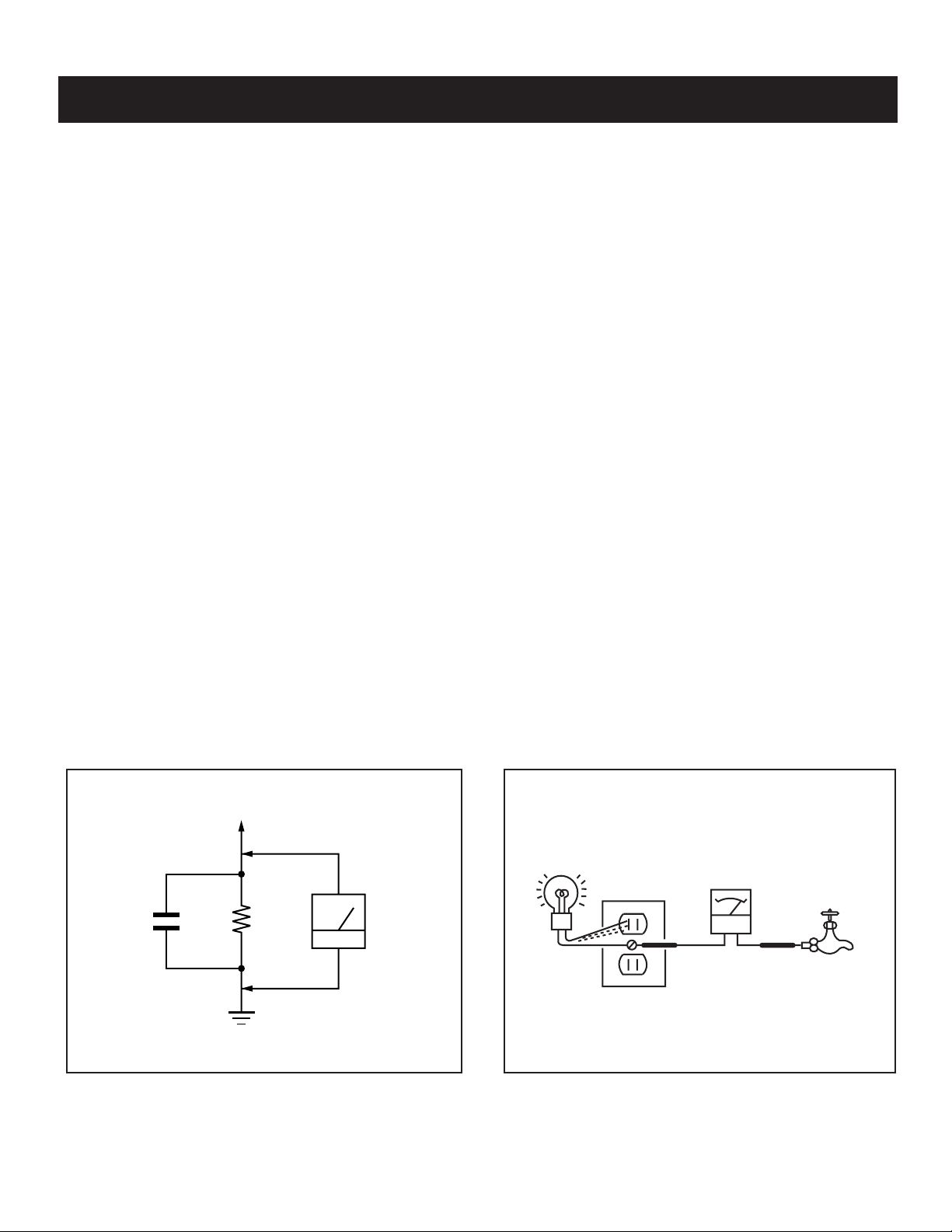
3. Measuring the voltage drop across a resistor by means of a VOM
or battery-operated AC voltmeter. The “limit” indication is 0.75 V,
so analog meters must have an accurate low voltage scale. The
Simpson’s 250 and Sanwa SH-63TRD are examples of passive
VOMs that are suitable. Nearly all battery-operated digital
multimeters that have a 2 VAC range are suitable (see Figure A).
How to Find a Good Earth Ground
A cold-water pipe is a guaranteed earth ground; the cover-plate
retaining screw on most AC outlet boxes is also at earth ground. If the
retaining screw is to be used as your earth ground, verify that it is at
ground by measuring the resistance between it and a cold-water pipe
with an ohmmeter. The reading should be zero ohms.
If a cold-water pipe is not accessible, connect a 60- to 100-watt troublelight (not a neon lamp) between the hot side of the receptacle and the
retaining screw. Try both slots, if necessary, to locate the hot side on
the line; the lamp should light at normal brilliance if the screw is at
ground potential (see Figure B).
To Exposed Metal
Parts on Set
0.15 F
1.5 K Ω
Earth Ground
Figure A. Using an AC voltmeter to check AC leakage. Figure B. Checking for earth ground.
KD-27FS170/32FS170/36FS170
AC
Voltmeter
(0.75 V)
Trouble Light
AC Outlet Box
Ohmmeter
Cold-water Pipe
6
Page 7
KD-27FS170/32FS170/36FS170
SELF-DIAGNOSTIC FUNCTION
Self Diagnosis
Supported model
The units in this manual contain a self-diagnostic function. If an error occurs, the STANDBY/TIMER LED will automatically begin to fl ash. The number of
times the LED fl ashes translates to a probable source of the problem. A defi nition of the STANDBY/TIMER LED fl ash indicators is listed in the instruction
manual for the user’s knowledge and reference. If an error symptom cannot be reproduced, the Remote Commander can be used to review the failure
occurrence data stored in memory to reveal past problems and how often these problems occur.
Diagnostic Test Indicators
When an error occurs, the STANDBY/TIMER LED will fl ash a set number of times to indicate the possible cause of the problem. If there is more than one
error, the LED will identify the fi rst of the problem areas.
Results for all of the following diagnostic items are displayed on screen. No error has occurred if the screen displays a “0”.
Diagnostic Item Descrip-
tion
Power does not turn on
+B overcurrent (OCP)*
I-Prot
IK (AKB)
No. of times
STANDBY/ TIMER
lamp fl ashes
Does not light
2 times
4 times
5 times
Self-Diagnositc
Display/ Diagnos-
tic Result
2:0 or 2:1
4:0 or 4:1
5:0 or 5:1
Probable Cause Location
• Power cord is not plugged in.
• Fuse is burned out (F601). (A Board)
• H.OUT (Q502) is shorted. (A Board)
• IC702 is shorted. (CV Board)
• +13V is not supplied. (A Board)
• IC561 is faulty. (A Board)
• IC001 is faulty. (A Board)
• Screen (G2) is improperly adjusted.**
Detected Symptoms
• Power does not come on.
• No power is supplied to the TV.
• AC Power supply is faulty.
• Power does not come on.
• Load on power line is shorted.
• Has entered standby state after horizontal raster.
• Vertical defl ection pulse is stopped.
• Power line is shorted or power supply is stopped.
• No raster is generated.
• CRT Cathode current detection reference pulse
output is small.
*If a +B overcurrent is detected, stoppage of the vertical defl ection is detected simultaneously. The symptom that is diagnosed fi rst by the mircrocontroller
is displayed on the screen.
**Refer to Screen (G2) Adjustments in Section 2-4. of this manual.
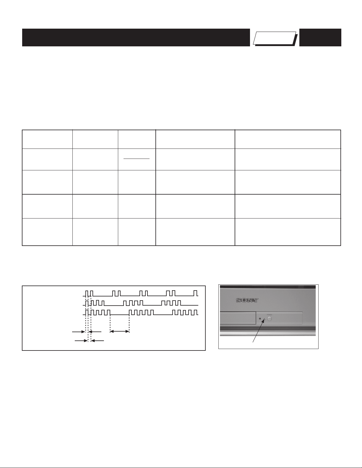
Display of Standby/Timer LED Flash Count
2 times
4 times
5 times
LED ON 0.3 sec.
LED OFF 0.3 sec.
LED OFF
3 sec.
Standby/Timer LED
Diagnostic Item Flash Count*
+B Overcurrent 2 times
I-Prot 4 times
IK (AKB) 5 times
*One fl ash count is not used for self-diagnostic.
Stopping the Standby/Timer LED Flash
Turn off the power switch on the TV main unit or unplug the power cord from the outlet to stop the STANDBY/TIMER LAMP from fl ashing.
KD-27FS170/32FS170/36FS170
7
Page 8

KD-27FS170/32FS170/36FS170
Self-Diagnostic Screen Display
For errors with symptoms such as “power sometimes shuts off” or “screen sometimes goes out” that cannot be confi rmed, it is possible to bring up past
occurrences of failure on the screen for confi rmation.
To Bring Up Screen Test
In standby mode, press buttons on the Remote Commander sequentially, in rapid succession, as shown below:
DISPLAY
Self-Diagnostic Screen Display
Handling of Self-Diagnostic Screen Display
Since the diagnostic results displayed on the screen are not automatically cleared, always check the self-diagnostic screen during repairs. When you
have completed the repairs, clear the result display to “0”.
Unless the result display is cleared to “0”, the self-diagnostic function will not be able to detect subsequent faults after completion of the repairs.
Clearing the Result Display
To clear the result display to “0”, press buttons on the Remote Commander sequentially when the diagnostic screen is displayed, as shown below:
Channel 8
Quitting the Self-Diagnostic Screen
To quit the entire self-diagnostic screen, turn off the power switch on the Remote Commander or the main unit.
Channel
SELF DIAGNOSTIC
2: +B OCP 0
3: +B OVP N/A
4: VSTOP 0
5: AKB 1
101: WDT N/A
ENTER
5
Sound Volume -
Numeral “0” means that no fault was detected.
Numeral “1” means a fault was detected one time only.
POWER
Note that this differs from entering the Service Mode (Sound Volume
+
).
Self-Diagnostic Circuit
FROM
CV BOARD
IC702 PIN 5
A BOARD
IC001
Y/CHROMA JUNGLE
51
IK-AKBIN
A BOARD
IC561
V. OUT
REF
3
A BOARD
IC001
SYSTEM
IO-BDAT
78
I-Prot
53
A BOARD
IC002
MEMORY
5
BDA
FROM
72
A BOARD
IC501
PIN 1
+B overcurrent (OCP)
Occurs when an overcurrent on the +B (135V) line is detected by pin 72 of IC001 (A Board). If the voltage of pin 72 of IC001 (A Board) is less than 1V
when V.SYNC is more than seven verticals in a period, the unit will automatically turn off.
I-Prot
Occurs when an absence of the vertical defl ection pulse is detected by pin 78 of IC001 (A Board). Power supply will shut down when waveform interval
exceeds 2 seconds.
IK (AKB)
If the RGB levels* do not balance within 2 seconds after the power is turned on, this error will be detected by IC001 (A Board). TV will stay on, but there
will be no picture.
I-HLDWN
O-LED
1
DISPLAY
*(Refers to the RGB levels of the AKB detection Ref pulse that detects IK).
KD-27FS170/32FS170/36FS170
8
Page 9
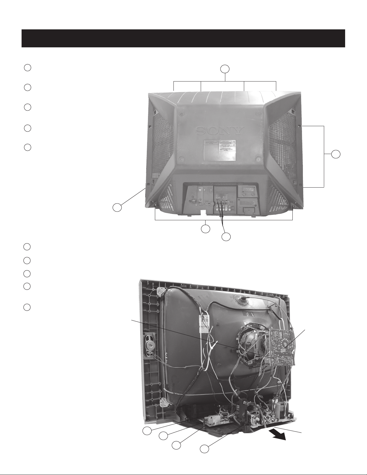
1-1. REAR COVER REMOVAL
1
Remove screws from top of cover.
4 Screws
2
Remove screws from sides of cover.
4 Screws
3
Remove screws from bottom of cover.
2 Screws
Remove screws from back of cover.
4
3 Screws
Remove rear cover
5
SCREW +BVTP 4X16 TYPE2 TT (B)
SCREW +BVTP 4X16 TYPE2 TT (B) - 2
SCREW +BVTP 4X16 TYPE2 TT (B)
SCREW +BVTP 3X12 TYPE2 TT (B)
KD-27FS170/32FS170/36FS170
SECTION 1: DISASSEMBLY
1
each side
2
5
1-2. CHASSIS ASSEMBLY REMOVAL
1
Release the M Board.
Release the A Board wires from Clip Holder.
2
Press on catch tab to release the A Board.
3
4
Remove Power Cable Holders by gently
rocking to release clips.
Gently pull the chassis forward.
5
VD Board
3
4
CV Board
KD-27FS170/32FS170/36FS170
4
3
2
1
Chassis Assembly
9
Page 10
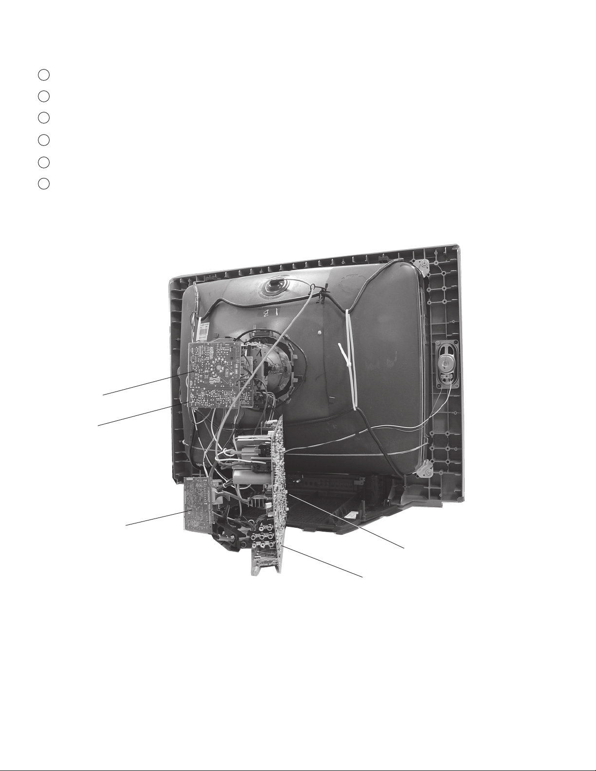
1-3. SERVICE POSITION
1
Release the M Board.
2
Release the A Board wires from Clip Holder.
3
Press on catch tab to release A Board.
Remove Power Cable Holders by gently rocking to release clips.
4
Gently pull the A Board forward until the HS Board has cleared the bracket.
5
Gently continuing pulling the A Board and HS Board forward to place in service position.
6
KD-27FS170/32FS170/36FS170
CV Board
VD Board
M Board
HS Board
A Board
KD-27FS170/32FS170/36FS170
10
Page 11
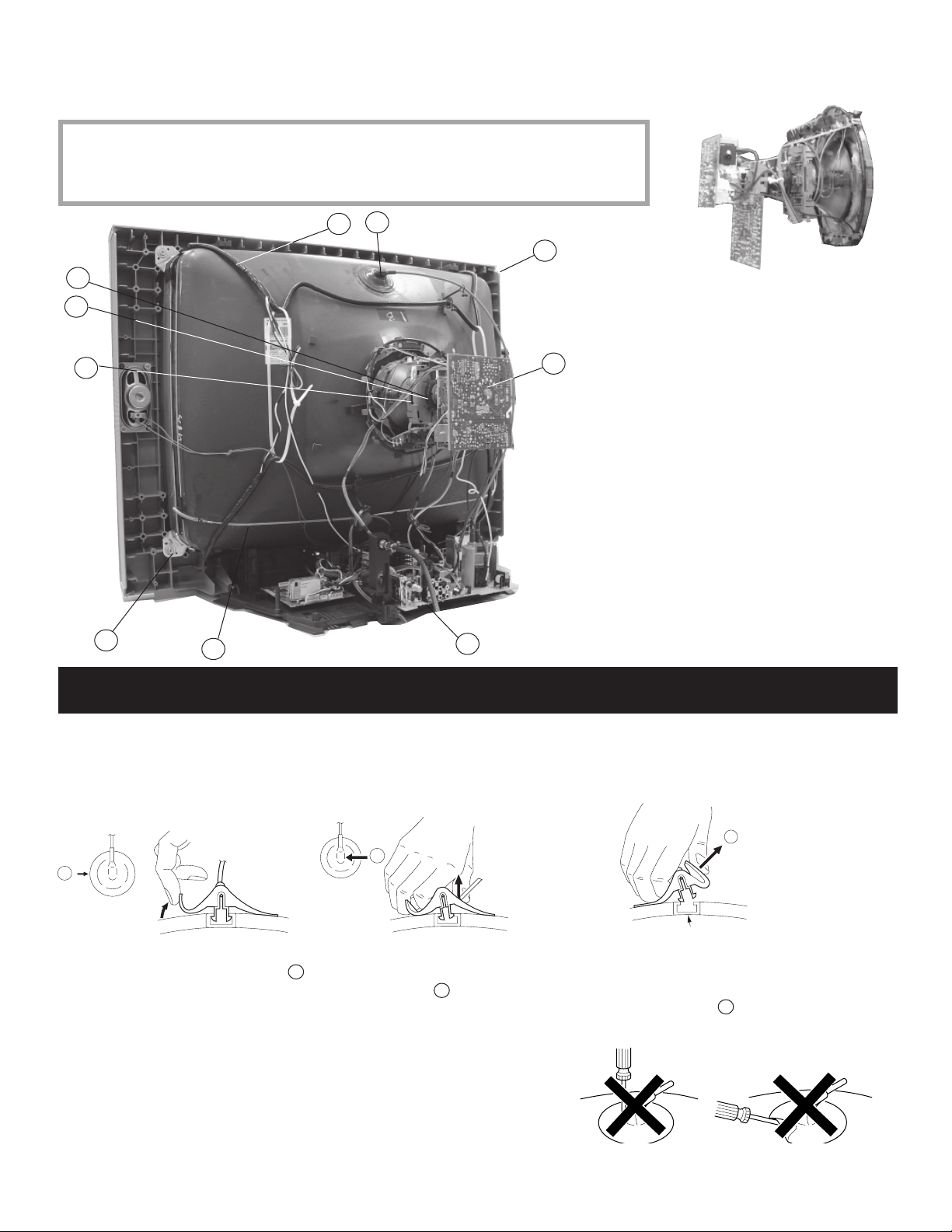
1-4. PICTURE TUBE REMOVAL
WARNING: BEFORE REMOVING THE ANODE CAP
High voltage remains in the CRT even after the power is disconnected. To avoid electric shock,
discharge CRT before attempting to remove the anode cap. Short between anode and CRT
coated earth ground strap.
1
8
7
KD-27FS170/32FS170/36FS170
2
5
6
10
9
4
3
1. Discharge the anode of the CRT and remove
the anode cap.
2. Unplug all interconnecting leads from the
defl ection yoke, neck assembly, degaussing
coils and CRT grounding strap.
3. Remove the CV Board from the CRT.
4. Remove the chassis assembly.
5. Loosen the neck assembly fi xing screw and
remove.
6. Loosen the defl ection yoke fi xing screw and
remove.
7. Place the set with the CRT face down on
a cushion and remove the degaussing coil
holders.
8. Remove the degaussing coils.
9. Remove the CRT grounding strap and spring
tension devices.
10. Unscrew the four CRT fi xing screws [located on
each CRT corner] and remove the CRT [Take
care not to handle the CRT by the neck].
ANODE CAP REMOVAL PROCEDURE
WARNING: High voltage remains in the CRT even after the power is disconnected. To avoid electric shock, discharge CRT before attempting to remove
the anode cap. Short between anode and coated earth ground strap of CRT.
NOTE: After removing the anode cap, short circuit the anode of the picture tube and the anode cap to either the metal chassis, CRT shield, or carbon
painted on the CRT.
REMOVAL PROCEDURES
c
b
a
Anode Button
Turn up one side of the rubber cap in
the direction indicated by arrow a .
HOW TO HANDLE AN ANODE CAP
1. Do not use sharp objects which may cause damage to the surface of the
anode cap.
2. To avoid damaging the anode cap, do not squeeze the rubber covering too
hard. A material fi tting called a shatter-hook terminal is built into the rubber.
3. Do not force turn the foot of the rubber cover. This may cause the shatterhook terminal to protrude and damage the rubber.
KD-27FS170/32FS170/36FS170
Use your thumb to pull the rubber
cap fi rmly in the direction indicated
by arrow b .
When one side of the rubber cap separates from
the anode button, the anode cap can be removed
by turning the rubber cap and pulling it in the
direction of arrow c .
11
Page 12
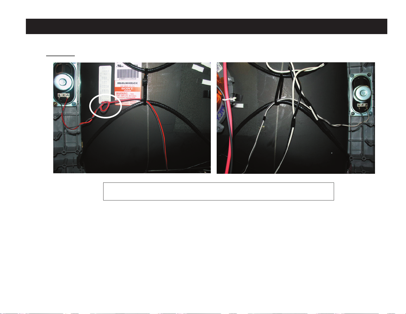
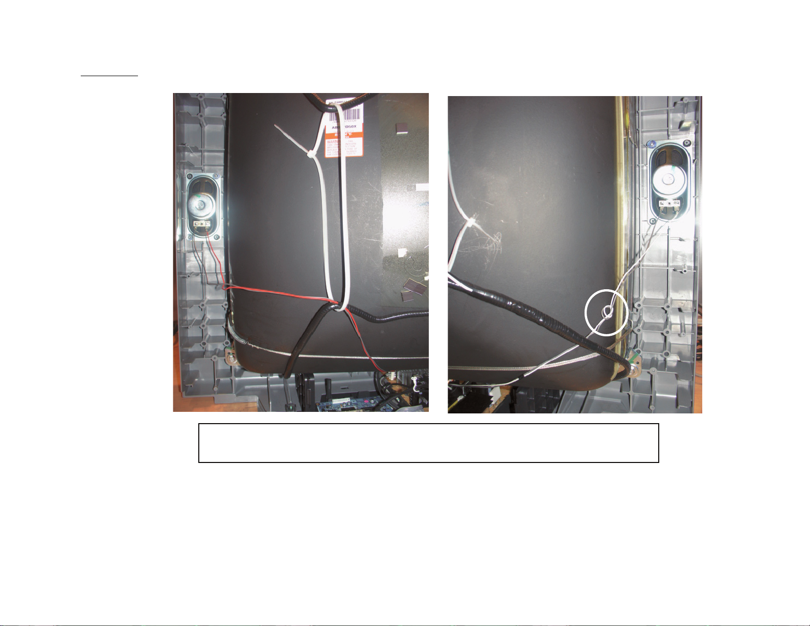
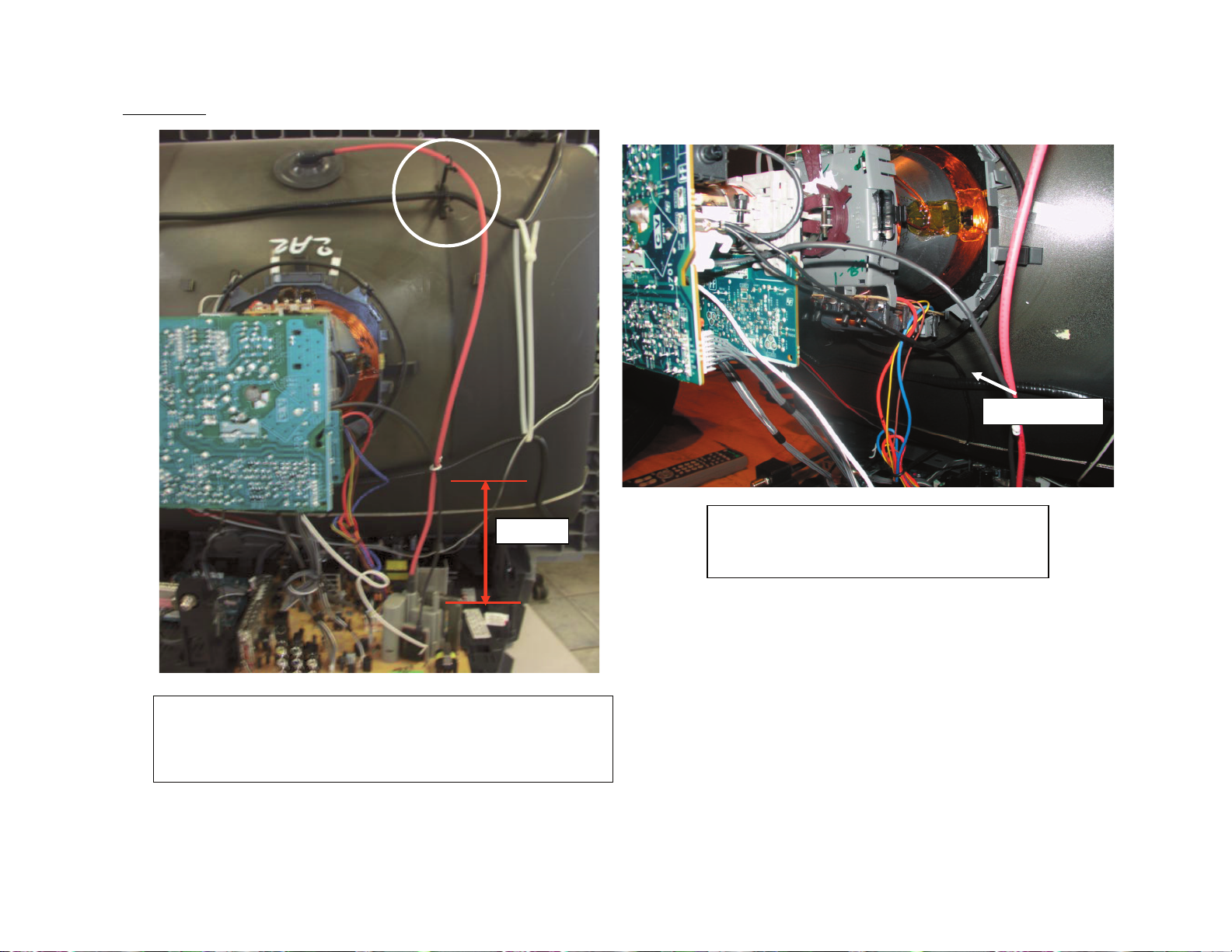
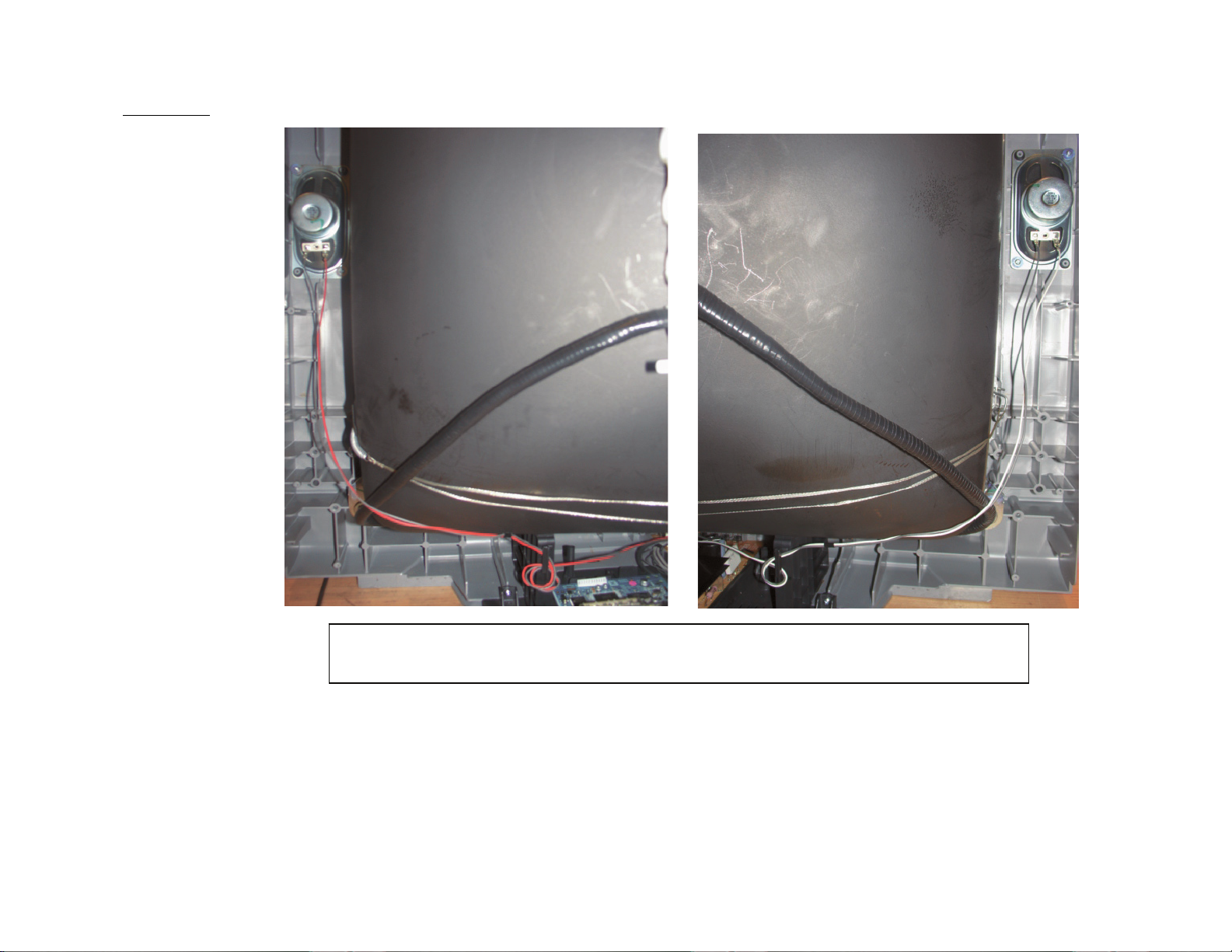
CABLE WIRE DRESSING
KD-27FS170 MODELS ONLY
KD-27FS170
KD-27FS170/32FS170/36FS170
KD-27FS170/32FS170/36FS170
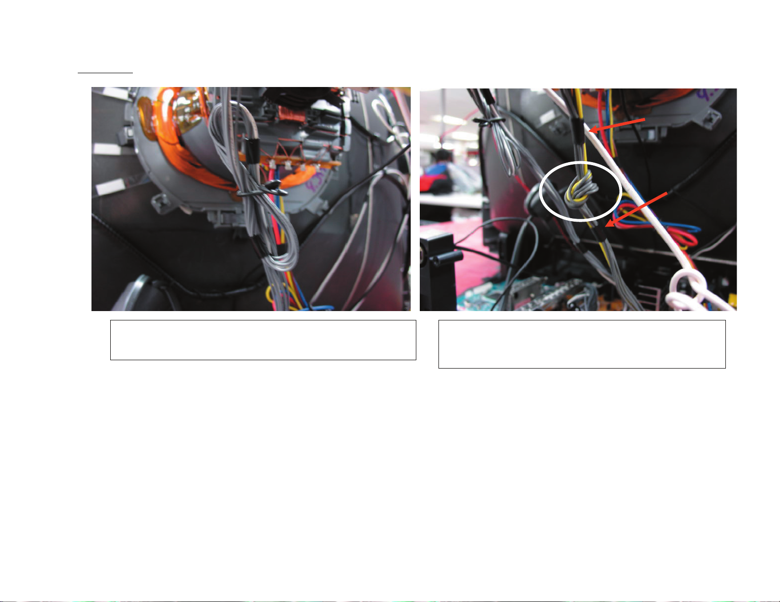
- Dress Right & left speaker wire through DGC's tie wrap as picture shows.
- Make a knot in Right speaker wire as shown in picure
12
Page 13
KD-27FS170
KD-27FS170/32FS170/36FS170
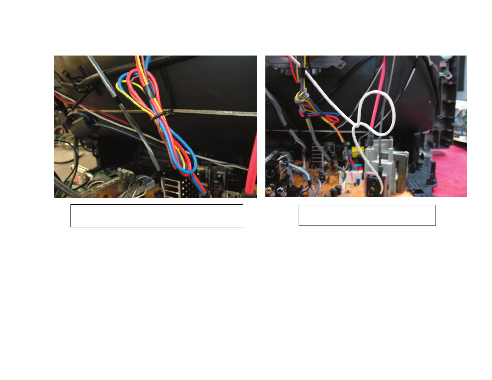
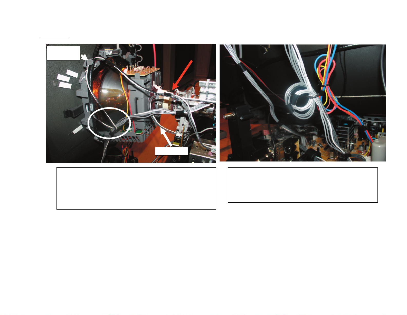
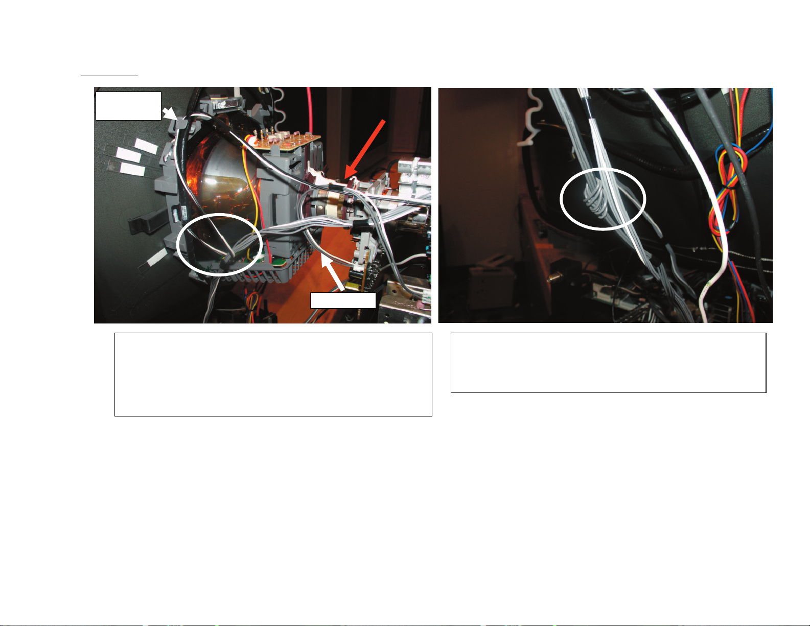
Dress RGB harness (A/CN301~ C/CN705) using a 9mm
purse lock (3-703-982-02).
KD-27FS170/32FS170/36FS170
Make a knot in Heater (A/CN503~C/CN901) harness
between black tapes as shown in picture.
13
Page 14
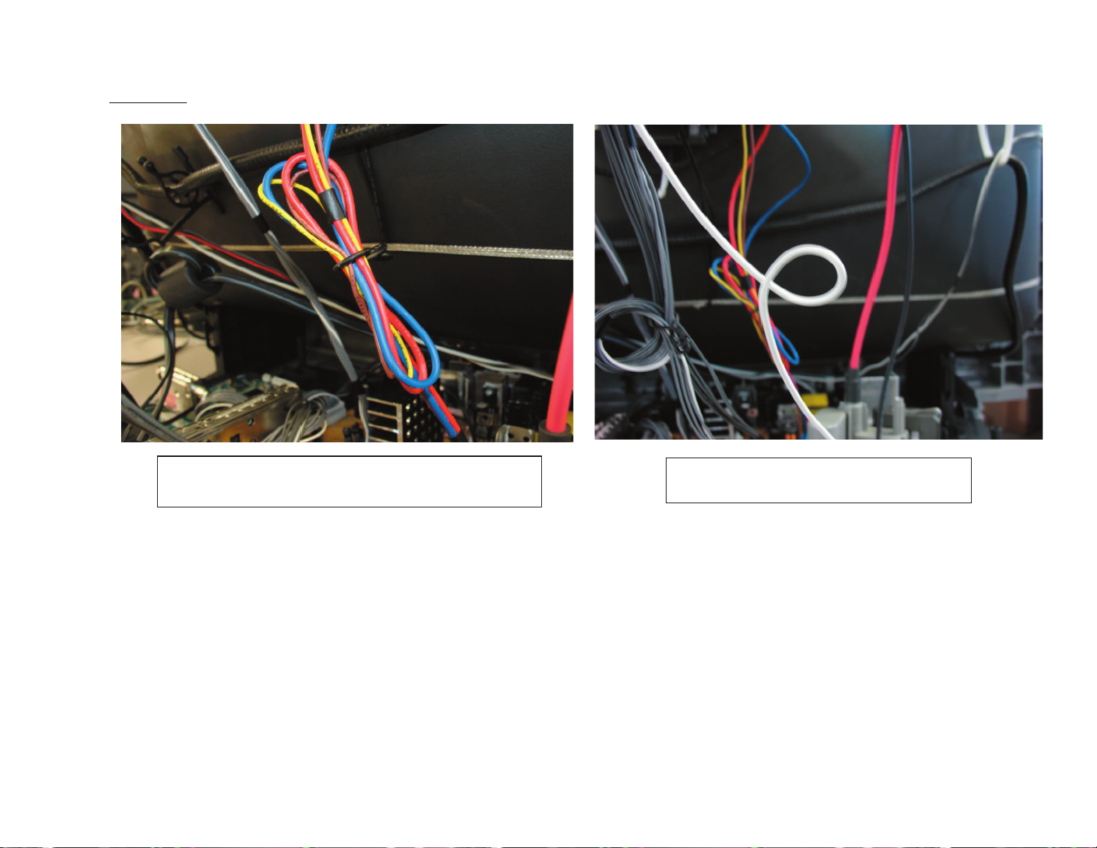
KD-27FS170
KD-27FS170/32FS170/36FS170
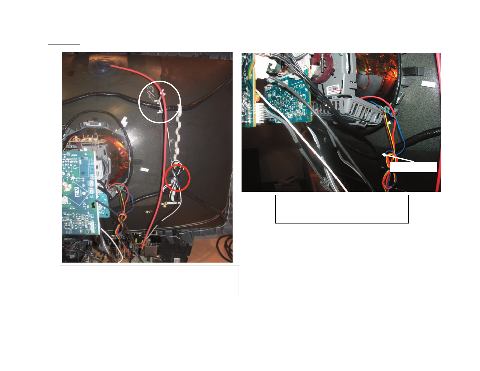
Dress DY's lead wire using a 9mm purse lock (3703-982-02).
KD-27FS170/32FS170/36FS170
Dress G2 wire twist once as picture
shown, do not over stress wire.
14
Page 15

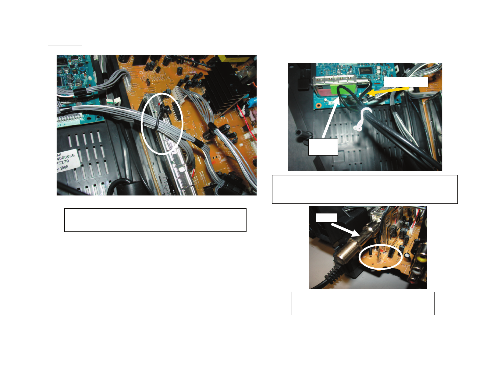
KD-27FS170
KD-27FS170/32FS170/36FS170
Coaxial cable
Ground
cable
9P harness
Dress 9P harness (A/CN004~M/CN1100) & 12P
(HS/CN1004~A/CN303 using a 9mm purse lock (3-703-982-02) &
pass over analog tuner as shown in picture.
Dress ground & coaxial cable of digital module using
a 5mm purse lock (3-703-981-02) as shown in picture.
F-Pin
Connect ground cable in plug CN612 & pass
beside F-Pin as shown in picture.
KD-27FS170/32FS170/36FS170
15
Page 16
KD-27FS170
KD-27FS170/32FS170/36FS170
12P harness
Wire Holder
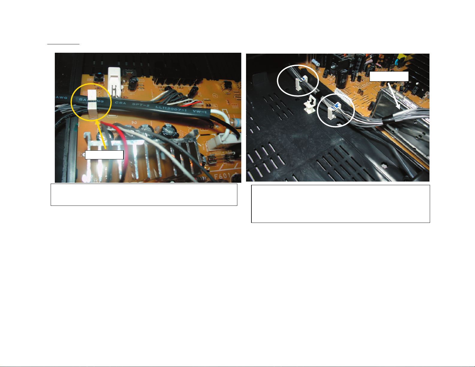
- Fix 12P harness (HS/CN1004~A/CN303) ,Lightening
cable & AC-Cord using a wire holder (4-065-850-11)
KD-27FS170/32FS170/36FS170
- Fix12P (HS/CN1004~A/CN303) harness, lightening
cable & AC-Cord using 2 wire holder (4-065-850-11). Pass 12P (HS/CN1004~A/CN303) over tuner as shown
in picture.
16
Page 17

KD-27FS170
KD-27FS170/32FS170/36FS170
30 ±1 cm
Behind DGC
15 ±1 cm
Dress focus lead and HV cable together using 5mm purse lock
(3-703-981-02)
KD-27FS170/32FS170/36FS170
Dress CRT ground behind DGC & pass
through CV board hook as shown in
picture.
17
Page 18
KD-27FS170
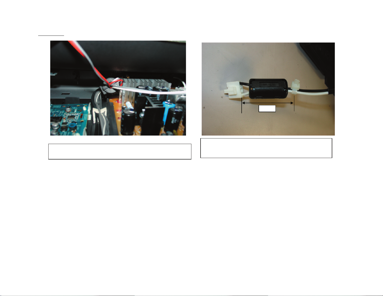
Pass audio ferrite beside heat sink as shown in picture (left side
of heat sink back view)
KD-27FS170/32FS170/36FS170
50mm
Install Chisilin ferrite core 1-500-586-11 on DGC
and use a cable tie 4-041-041-11 to avoid movement of
ferrite as shown in picture.
KD-27FS170/32FS170/36FS170
18
Page 19
KD-32FS170 MODELS ONLY
KD-32FS170
KD-27FS170/32FS170/36FS170
KD-27FS170/32FS170/36FS170
- Dress Right speaker wire through DGC's tie wrap.
- Dress Left speaker wire under DGC and make a knot as picture shows.
19
Page 20
KD-32FS170
Rotation coil
wire.
KD-27FS170/32FS170/36FS170
VM harness
- Pass RGB harness (A/CN301~ C/CN705) through
rotation coil using.
- Install rotation coil lead wire under DY clip.
- Pass VM harness over rotation coil lead & RGB
harness as shown in picture.
KD-27FS170/32FS170/36FS170
Dress Heater (A/CN503~C/CN901) & Dinamic focus
(A/CN502~VD/CN800) harness, make a loop using a
9mm purse lock (3-703-982-02) as shown in picture.
20
Page 21
KD-32FS170
KD-27FS170/32FS170/36FS170
Dress DY's lead wire using a 9mm purse lock (3703-982-02).
KD-27FS170/32FS170/36FS170
Dress G2 wire twist once as picture
shown, do not over stress wire.
21
Page 22

KD-32FS170
KD-27FS170/32FS170/36FS170
12P harness
Wire Holder
- Fix 12P harness (HS/CN1004~A/CN303) ,Lightening
cable & AC-Cord using a wire holder (4-065-850-11)
KD-27FS170/32FS170/36FS170
- Fix12P (HS/CN1004~A/CN303) harness, lightening
cable & AC-Cord using 2 wire holder (4-065-850-11). Pass 12P (HS/CN1004~A/CN303) over tuner as shown
in picture.
22
Page 23
KD-32FS170
9P harness
9P harness
KD-27FS170/32FS170/36FS170
Coaxial cable
Ground
cable
Dress ground & coaxial cable of digital module using
a 5mm purse lock (3-703-981-02) as shown in picture.
Dress 9P harness (A/CN004~M/CN1100) & 12P
(HS/CN1004~A/CN303 using a 9mm purse lock (3-703-982-02) &
pass over analog tuner as shown in picture.
KD-27FS170/32FS170/36FS170
F-Pin
Connect ground cable in plug CN612 & pass
beside F-Pin as shown in picture.
23
Page 24
KD-32FS170
KD-27FS170/32FS170/36FS170
Behind DGC
Install purse lock (4-081-411-02) using carbon paint as reference.
Dress focus lead and HV cable together using 5mm purse lock
(3-703-981-02)
KD-27FS170/32FS170/36FS170
15 ±1 cm
Dress CRT ground behind DGC & pass
beside VD board and under Focus lead
as shown in picture.
24
Page 25
KD-36FS170 MODELS ONLY
KD-36FS170
KD-27FS170/32FS170/36FS170
KD-27FS170/32FS170/36FS170
- Dress Right speaker wire using CRT's hook (2 loops).
- Dress Left speaker wire using CRT's hook (1 loop) as picture shows.
25
Page 26
KD-36FS170
Rotation coil
wire.
KD-27FS170/32FS170/36FS170
VM harness
- Pass RGB harness (A/CN301~ C/CN705) through
rotation coil using.
- Install rotation coil lead wire under DY clip.
- Pass VM harness over rotation coil lead & RGB
harness as shown in picture.
KD-27FS170/32FS170/36FS170
Make a knot in Heater harness (A/CN503~C/CN901)
and interlace once with Dinamic focus
(A/CN502~VD/CN800) harness, as shown in picture.
26
Page 27

KD-36FS170
KD-27FS170/32FS170/36FS170
Dress DY's lead wire using a 9mm purse lock (3703-982-02).
KD-27FS170/32FS170/36FS170
Dress G2 & Focus wire as shown in
picture, G2 wire behind VD board &
Focus wire beside VD board.
27
Page 28

KD-36FS170
KD-27FS170/32FS170/36FS170
12P harness
Wire Holder
- Fix 12P harness (HS/CN1004~A/CN303) ,Lightening
cable & AC-Cord using a wire holder (4-065-850-11)
KD-27FS170/32FS170/36FS170
- Fix12P (HS/CN1004~A/CN303) harness, lightening
cable & AC-Cord using 2 wire holder (4-065-850-11). Pass 12P (HS/CN1004~A/CN303) over tuner as shown
in picture.
28
Page 29

KD-36FS170
9P harness
9P harness
9P harness
KD-27FS170/32FS170/36FS170
Coaxial cable
Ground
cable
Dress ground & coaxial cable of digital module using
a 5mm purse lock (3-703-981-02) as shown in picture.
Dress 9P harness (A/CN004~M/CN1100) & 12P
(HS/CN1004~A/CN303 using a 9mm purse lock (3-703-982-02) &
pass over analog tuner as shown in picture.
KD-27FS170/32FS170/36FS170
F-Pin
Connect ground cable in plug CN612 & pass
beside F-Pin as shown in picture.
29
Page 30
KD-36FS170
KD-27FS170/32FS170/36FS170
Behind DGC
- Fix HV Cable using a purse lock (4-089-469-11) take carbon
paint as reference.
- Fix DGC lead wire to DGC's tie wrap with a 9mm purse lock (3703-982-02)
KD-27FS170/32FS170/36FS170
Dress CRT ground behind DGC & pass
beside VD board as shown in picture.
30
Page 31

SECTION 2: SET-UP ADJUSTMENTS
KD-27FS170/32FS170/36FS170
The following adjustments should be made when a complete realignment
is required or a new picture tube is installed.
These adjustments should be performed with rated power supply voltage
unless otherwise noted.
Set the controls as follows unless otherwise noted:
VIDEO MODE: Pro
PICTURE CONTROL: Normal
BRIGHTNESS CONTROL: Normal
2-1. BEAM LANDING
Before beginning adjustment procedure:
1. Feed in the white pattern signal.
Adjustment Procedure
1. Input a raster signal with the pattern generator.
2. Loosen the defl ection yoke mounting screw, and set the purity
control to the center as shown below:
Purity Control
Perform the adjustments in order as follows:
1. Beam Landing
2. Convergence
3. Focus
4. Screen (G2)
5. White Balance
Note Test Equipment Required:
1. Color Bar Pattern Generator
2. Degausser
3. DC Power Supply
4. Digital Multimeter
6. Switch over the raster signal to red and blue and confi rm the
condition.
7. When the position of the defl ection yoke is determined, tighten it
with the defl ection yoke mounting screw.
8. If landing at the corner is not right, adjust by using the disk
magnets.
3. Turn the raster signal of the pattern generator to green.
4. Move the defl ection yoke backward, and adjust with the purity
control so that green is in the center and red and blue are even on
both sides.
Blue Red
Green
5. Move the defl ection yoke forward, and adjust so that the entire
screen becomes green.
KD-27FS170/32FS170/36FS170
Purity control
corrects this area.
Disk magnets
or rotatable disk
magnets correct
these areas (a-d).
Deflection yoke positioning
b
d
a
b
cd
corrects these areas.
a
c
31
Page 32

KD-27FS170/32FS170/36FS170
2-2. CONVERGENCE
Before starting convergence adjustments:
1 Perform FOCUS, VLIN and VSIZE adjustments.
2. Set BRIGHTNESS control to minimum.
3. Feed in dot pattern.
Vertical Static Convergence
1. Adjust V. STAT magnet to converge red, green and blue dots in the
center of the screen.
Center dot
RV701
R
B
G
H.STAT
R
G
B
Horizontal Static Convergence
If the blue dot does not converge with the red and green dots, perform
the following:
1. Move H STAT VR magnet (a) to correct insuffi cient H.Static
convergence.
V. STAT
BMC MAGNET
PURITY
V.STAT magnet
2. Tilt the V. STAT magnet and adjust static convergence to open or
close the V. STAT magnet.
When the V. STAT magnet is moved in the direction of arrow a and
b, red, green, and blue dots move as shown below:
1
a
b
2
a
a
b
B
G
R
b
b
B
G
R
a
RGB
b
BGR
3
b
a
a
R
G
b
KD-27FS170/32FS170/36FS170
b
B
G
B
R
32
Page 33

Dynamic Convergence Adjustment
Before performing this adjustment, perform Horizontal and Vertical Static
Convergence Adjustment.
1. Slightly loosen defl ection yoke screw.
2. Remove defl ection yoke spacers.
3. Move the defl ection yoke for best convergence as
shown below:
G
B
R
R
G
B
BGR
B
G
R
R
B
G
R
B
G
KD-27FS170/32FS170/36FS170
B R R B
(R)(B) (B)(R)
4. Adjust XCV core to balance X axis.
5. Adjust YCH VR to balance Y axis.
6. Adjust vertical red and blue convergence with V.TILT (TLV VR.)
Note: Perform adjustment 3-6 while tracking items 1 and 2.
TLH+
TLH-
Screen-Corner Convergence
BGR
B
G
R
B
G
R
B
R
G
B
R
G
R
GB
4. Tighten the defl ection yoke screw.
5. Install the defl ection yoke spacers.
TLH Plate Adjustment
1. Input crosshatch pattern.
2. Adjust PICTURE QUALITY to standard, PICTURE and
BRIGHTNESS to 50%, and OTHER to standard.
3 Adjust the Horizontal Convergence of red and blue dots by tilting
the TLH plate on the defl ection yoke.
RV701
V.STAT
TLH Plate
1. Affi x a permalloy assembly corresponding to the misconverged
areas:
b
a
ba
a-d: screen-corner
misconvergence
c
d
c
d
2-3. FOCUS
1. Adjust FOCUS control for best pictures.
Focus (FV)
Screen (G2)
C
Board
(TLV)
KD-27FS170/32FS170/36FS170
XCV
YCH
TLV
33
Page 34

2-4. SCREEN (G2)
1. Input a dot pattern.
2. Set the PICTURE and BRIGHTNESS controls at minimum and
COLOR control at normal.
3. Adjust SBRT, GCUT, BCUT in service mode with an oscilloscope as
shown below so that voltages on the red, green, and blue cathodes
are 170 ± 2VDC.
±
170 ± 2VDC
Ground
4. Observe the screen and adjust SCREEN (G2) VR in FBT to obtain
the faintly visible background of dot signal.
Pedestal
KD-27FS170/32FS170/36FS170
KD-27FS170/32FS170/36FS170
34
Page 35

SECTION 3: SAFETY RELATED ADJUSTMENTS
KD-27FS170/32FS170/36FS170
3-1. X R529, R530, R531, R577
CONFIRMATION METHOD
(HV HOLD-DOWN CONFIRMATION) AND
READJUSTMENTS
Hold-Down Readjustment
If the setting indicated in Step 2 of Hold-Down Operation Confi rmation
cannot be met, readjustment should be performed by altering the
resistance value of R529, R530, R531 and R577 component marked with
X
The following adjustments should always be performed when replacing
the following components which are marked with
Y
on the schematic
diagram:
Part Replaced ( ) Adjustment ( )
C507, C511, C513, D519,
D520, D521, IC001, IC501,
Y
HV HOLD-DOWN
R529, R530, R531, R577
IC601, IC602, PH601, R529,
R530, R531, R577, T502,
T503 (FBT), T505
Preparation Before Confi rmation
1. Using a Variac, apply AC input voltage: 120 +/- 2.0 VAC.
2. Turn the POWER switch ON.
3. Input a white signal and set the PICTURE and BRIGHT controls to
maximum.
4. Confi rm that the voltage of more than 23.0 VDC appears between
TP85 and ground on the A Board.
3-2. B+ VOLTAGE CONFIRMATION AND
Hold-Down Operation Confi rmation
.
R529 R577
R531
DC Power Supply
ADJUSTMENT
digital multimeter
+
-
TP85
TP85
R530
+
-
Figure 1
T503
FBT
FBT
ammeter
3mA DC range
A
+
-
1. Connect the current meter between Pin 11 of the FBT (T503) and
the PWB land where Pin 11 would normally attach. (See Figure 1).
2. Input a dot signal and set PICTURE and BRIGHTNESS to
minimum: IABL = 2175 + 100/ -325 µA.
3. Confi rm the voltage of A Board TP91 is 134.6 ± 1.0 VDC.
4. Connect the digital voltmeter and the DC power supply to TP85 and
ground. (See Figure 1).
5. Increase the DC power voltage gradually until the picture blanks
out.
6. Turn DC power source off immediately.
7. Read the digital voltmeter indication:
Standard = 24.78 + 0.0/ - 0.1 VDC.
8. Input a white signal and set PICTURE and BRIGHTNESS to
maximum: IABL = 2175 + 100/ -325 µA.
9. Repeat steps 4 to 7.
Always perform the following adjustments when replacing the following
components, which are marked with
Y
on the schematic diagram on the
A Board:
Adjustment (Y)
A BOARD
IC600, PH602
1. Using a Variac, apply AC input voltage: 130 + 2.0/-0.0 VAC
2. Input a monoscope signal.
3. Set the PICTURE control and the BRIGHT control to
minimum.
4. Confi rm the voltage on A Board between TP23 and ground is less
than 136.5 VDC.
5. If step 4 is not satisfi ed, replace R529, R530, R531 and R577 on A
Board and repeat the above steps.
KD-27FS170/32FS170/36FS170
35
Page 36

SECTION 4: CIRCUIT ADJUSTMENTS
Electrical Adjustments by Remote Commander
Use the Remote Commander (RM-YD006) to perform the circuit adjustments in this section.
Test Equipment Required: 1. Pattern generator 2. Frequency counter 3. Digital multimeter 4. Audio oscillator
KD-27FS170/32FS170/36FS170
4-1. REMOTE ADJUSTMENT BUTTONS AND
INDICATORS
MUTING
(Enter into
memory)
1
Display next
Item
2
Display next
Category
4
Display previous
Item
8
(Initialize)
VOLUME (+)
(Service Mode)
POWER
(Service Mode)
DISPLAY
(Service Mode)
3
Increase
Data value
6
Decrease
Data value
5
Display previous
Category
ENTER
(Enter into
memory)
0
(Remove from
memory)
4-2. ACCESSING THE SERVICE
ADJUSTMENT MODE
1. Standby mode (Power off).
2. Press the following buttons on the remote commander within a
second of each other:
DISPLAY
POWER
The screen displays the fi rst service data category item.
1. On the Remote Commander press 2 or 5 to select the category.
2. Press 1 or 4 to select the item.
3. Press 3 or 6 to change the data value.
4. Press
Display
Item
Display
Data
Channel
Category
Display
Item
Display
Data
MUTING
Category
HSIZ 1:35 NVM:OK
HSIZ 1:35 NVM:OK
M65586MK-056FP D1.0
then
5
Sound Volume +
ENTER
Signal
Type
NTSC WRITEDEF
Signal
Type
NTSC VIDEO1DEF
to write into memory.
Channel
Type
Channel
Type
Text
changes to
“WRITE” and
changes
colors from
green to red
RM-YD006
KD-27FS170/32FS170/36FS170
M65586MK-056FP D1.0
36
Page 37

KD-27FS170/32FS170/36FS170
Service Adjustment Mode Memory
4-3. CONFIRMING SERVICE ADJUSTMENT
Use the following procedure when adjusting IDs 0-7 and when replacing
and adjusting IC002.
1. Access Service Adjustment Mode.
2. Press 8 then
Category
Display
Item
Display
Data
ENTER
HSIZ 1:35 NVM:OK
M65586MK-056FP D1.0
on the Remote Commander to initialize.
Signal
Type
NTSC RESETDEF
Channel
Type
Text
changes to
“RESET”
and changes
colors from
green to red
1. After completing adjustments, pull out the plug from the AC outlet,
2. Access Service Adjustment Mode.
3. Using the buttons on the Remote Commander, locate the adjusted
The TV powers off after completing the initialization process.
CHANGES
then replace the plug in the AC outlet again.
items again to confi rm they were adjusted.
KD-27FS170/32FS170/36FS170
37
Page 38

4-4. WHITE BALANCE ADJUSTMENTS
1. Input an entire white signal with burst.
2. Access Service Adjustment Mode.
3. Set the PICTURE and BRIGHTNESS to minimum.
4. Adjust with SBRT if necessary.
5. Press
6. Press 1 or 4 to display the GCUT item.
7. Press 3 or 6 to adjust for the best white balance.
8. Press 1 or 4 to display the BCUT item.
9. Press 3 or 6 to adjust for the best white balance.
10. Set the PICTURE and BRIGHTNESS to maximum.
11. Press 1 or 4 to display the GDRV item.
12. Press 3 or 6 to adjust for the best white balance.
13. Press 1 or 4 to display the BDRV item.
14. Press 3 or 6 to adjust for the best white balance.
15. Press
2
or 5 to select the VP1 category.
ENTER
MUTING
then
to save into the memory.
4-5. A BOARD ADJUSTMENTS
H. Frequency (Free Run) Check
1. Input a TV mode (RF) with no signal.
2. Connect a frequency counter to base of Q501
(TP-25 H. DRIVE) on the A Board.
3. Check H. Frequency for 15735 ± 200 Hz.
KD-27FS170/32FS170/36FS170
80 + 2Vpp
12. Repeat steps 5 thru 8 to reset GON and BON values to “1”.
R ON: ON (1)
G ON: ON (1)
B ON: ON (1)
13. Press
MUTING
then
ENTER
to write into memory.
Display Position Adjustment (DISP)
1. Input a color-bar signal.
2. Access Service Adjustment Mode.
3. Press 2 or 5 to select the Microprocessor category.
4. Press 1 or 4 to display the DISP item.
5. Press 3 or 6 to adjust characters to the center.
6. Press
7. Check to see if the text is displayed on the screen.
MUTING
then
ENTER
to write into memory.
Sub Bright Adjustment (SBRT)
V. Frequency (Free Run) Check
1. Select video 1 with no signal input.
2. Set the conditions for a standard setting.
3. Connect the frequency counter to TP-27 (V OUT) or CN501 pin
(V DY+) and ground on the A Board .
4. Check that V. Frequency shows 60 ± 4 Hz.
6
Drive (SCON)
1. Input a color-bar signal and set the level to 75%.
2. Set in Pro mode + PICTURE MAX.
3. Access Service Adjustment Mode.
4. Press 2 or 5 to select the VP1 category.
5. Press 1 or 4 to display the GON item.
6. Press 3 or 6 to adjust to 0.
7. Press 1 or 4 to display the BON item.
8. Press 3 or 6 to adjust to 0.
Note: Leave RON set to “1”.
R ON: ON (1)
G ON: OFF (0)
B ON: OFF (0)
9. Connect an oscilloscope probe to C Board, CN705 pin3 (KR).
10. Press 1 or 4 to display the SCON item.
11. Press 3 or 6 to adjust the value of SCON to 80 ± 2Vpp.
1. Input a monoscope signal.
2. Access Service Adjustment Mode.
3. Set the PICTURE and BRIGHTNESS to minimum.
4. Press 2 or 5 to select the VP1 category.
5. Press 1 or 4 to display the SBRT item.
6. Press 3 or 6 to obtain a faintly visible 20 IRE mark, after that
increase +3 steps.
7. Press
MUTING
then
ENTER
to write into memory.
KD-27FS170/32FS170/36FS170
38
Page 39

KD-27FS170/32FS170/36FS170
Sub Hue, Sub Color Adjustment (SHUE, SCOL)
1. Input color-bar signal at 75%.
2. Access Service Adjustment Mode.
3. Set (PIC) to Max and (COL) to 50%.
4. Connect an oscilloscope probe to C Board, CN705 pin 4 (Blue
Out).
5. Press 2 or 5 to select the VP1 category.
6. Press 1 or 4 to display the SHUE or SCOL item.
7. While showing the SHUE item, adjust the waveform by pressing 3
or 6 until the second and third bars show the same level
(V2 = V3 < 0.15Vp-p). Set Sub Hue -2 Step.
8. While showing the SCOL item, adjust the waveform by pressing 3
or 6 until the fi rst and fourth bars show the same level
(V1 = V4 < 0.15Vp-p). Set Sub Col + 2 Step.
V2 V3
9. Press
MUTING
then
V1
ENTER
V4
to write into memory.
V. Size Adjustment (VSIZ)
H. Center Adjustment (HPOS)
Perform this adjustment after performing H. Frequency (Free Run)
Check.
1. Input a crosshatch signal.
2. Access Service Adjustment Mode.
3. Press 2 or 5 to select the DEF category.
4. Press 1 or 4 to display the HPOS item.
5. Adjust the value of HPOS by pressing 3 or 6 for the best horizontal
center.
6. Press
MUTING
then
ENTER
to write into memory.
H. Size Adjustment (HSIZ)
1. Input a monoscope signal.
2. Access Service Adjustment Mode.
3. Press 2 or 5 to select the DEF category.
4. Press 1 or 4 to display the HSIZ item.
5. Adjust value of HSIZ by pressing 3 or 6 for the best horizontal
size.
6. Press
MUTING
then
ENTER
to write into memory.
1. Input a crosshatch signal.
2. Access Service Adjustment Mode.
3. Press 2 or 5 to select the DEF category.
4. Press 1 or 4 to display the VSIZ item.
5. Adjust value of VSIZ by pressing 3 or 6 for the best vertical size.
6. Press
MUTING
then
ENTER
to write into memory.
V. Center Adjustment (VPOS)
Perform this adjustment after performing H. Frequency
(Free Run) Check.
1. Input a crosshatch signal.
2. Access Service Adjustment Mode.
3. Press 2 or 5 to select the DEF category.
4. Press 1 or 4 to display the VPOS item.
5. Adjust value of VPOS by pressing 3 or 6 for the best vertical
center.
6. Press
MUTING
then
ENTER
to write into memory.
KD-27FS170/32FS170/36FS170
39
Page 40

KD-27FS170/32FS170/36FS170
V. Linearity (VLIN), V. Correction (SCOR), PIN
Amp (PAMP), and Trapezoid (TRAP)
Adjustments
1. Input a crosshatch signal.
2. Access Service Adjustment Mode.
3. Press 2 or 5 to select the DEF category.
4. Press 1 or 4 to display the VLIN item.
5. Adjust the value of VLIN by pressing 3 or 6 for the best horizontal
size.
6. Repeat steps 4 and 5 for SCOR, PAMP, and TRAP.
7. Press
MUTING
V LINEARITY (VLIN)
V CORRECTION (SCOR)
PIN AMP (PAMP)
then
ENTER
to write into memory.
V. Angle (VANG), V. Bow (VBOW), Upper PIN
(UPIN) and Low PIN (LPIN) Adjustments
1. Input a crosshatch signal.
2. Access Service Adjustment Mode.
3. Press 2 or 5 to select the DEF category.
4. Press 1 or 4 to display the VANG item.
5. Adjust the value of VANG by pressing 3 or 6 for the best picture.
6. Repeat steps 4 and 5 for VBOW, UPIN, and LPIN.
7. Press
MUTING
V ANGLE (VANG)
V BOW (VBOW)
UPPER PIN (UPIN)
LOW PIN (LPIN)
then
ENTER
to write into memory.
TRAPEZOID (TRAP)
Reading Adjustments to Memory
1. After completing all adjustments, 0 then
memory.
Signal
Type
NTSC READDEF
Display
Item
Display
Data
Category
HSIZ 1:35 NVM:OK
M65586MK-056FP D1.0
ENTER
Channel
Type
to read into
Text
changes to
“READ” and
changes
colors from
green to red
KD-27FS170/32FS170/36FS170
40
Page 41

4-6. SERVICE DATA LISTS
KD-27FS170/32FS170/36FS170
KD-27FS170 MODELS ONLY
( = ) Means not memorized in NVM
Version 1.0
NTSC Video YUV Digital
Service
Group
Fix/
Var
Name
No. Description
Init Init Init Init
Data Data Data Data
VERSION Fix 0 ====
DEF
VAR
1HSIZ
VAR
2 HPOS H POSITION 25 25 25 18
VAR
3 VSIZ V RAMP SIZE 41
VAR
4VPOS
VAR
5VLIN
VAR
6SCOR
VAR
7VBOW
VAR
8VANG
VAR
9TRAP
VAR
10 PAMP
VAR
11 UPIN
VAR
12 LPIN
VAR
13 TROT TROT 109
VAR
14 HBLK
VAR
15 RBLK
VAR
16 LBLK
VAR
17 VBLK
FIX
18 HMSK
FIX
19 HDW
FIX
20 AFC
FIX
21 AFC1
FIX
21 AFC1
FIX
22 AFCW
FIX
23 CDMD V DET WINDOW SW TIMING 1
H SIZE(EW DC)
V POSITION(RAMP DC) 30 30 30 30
V LINEARITY
S CORRECTION
BOW
ANGLE
EW TRAPESIUM
EW PIN
UPPER PIN
LOWER PIN
H BLK mode select
HBLK rear timing
HBLK front timing
V BLK width
TOP VEND(when MACROVISION)prevent OFF 0
H PULSE WIDTH(25u 19u)
AFC GAIN
AFC1 TIME CONSTANT
AFC1 TIME CONSTANT 33 3
AFC1 PULL IN WIDE
24 24 24 26
41 41 41
38
51
32
19
35
32
31
30
0
29
59
3
1
0
3
1
31 31 31
60 60 60
KD-27FS170/32FS170/36FS170
41
Page 42

KD-27FS170 MODELS ONLY
KD-27FS170/32FS170/36FS170
Service
Group
DEF16:9
Fix/
No. Description
Var
FIX
24 HSS
FIX
25 VSS
FIX
26 SLUD
FIX
27 JPSW
FIX
28 HOSC
FIX
29 EHT EHT 4
FIX
30 EHTG EHT MODE 1
FIX
31 SLOH
FIX
32 SLOV
FIX
33 SLOP
FIX
34 SLVC
FIX
35 SLHC
FIX
36 VF50 VFREERUN 50Hz 0
FIX
37 VSET V FREQ SET 50\60 AUTO 0
VAR
1VSIZ
VAR
2VPOS
VAR
3VLIN
VAR
4SCOR
VAR
5TRAP
VAR
6PAMP
VAR
7UPIN
VAR
8LPIN
VAR
9ABLG
VAR
10 SCON
VAR
11 VPW
Name
SYNC SLICE LEVEL(H sepa)
SYNC SLICE LEVEL(V sepa)
Auto Slice level UP DOWN
Jump SW
H VCO fo offset ADJUST OFFSET
LPF SYNC H
LPF SYNC V
LPF SYNC
LPF SYNC VCOIN OFF
LPF SYNC HCOIN OFF 0
V RAMP SIZE
V POSITION(RAMP DC)
V LINEARITY
S CORRECTION 24
EW TRAPESIUM
EW PIN
UPPER PIN
LOWER PIN
ABL GAIN
SUB CONTRAST LEVEL
Jump Pulse Width
NTSC Video YUV Digital
Init Init Init Init
Data Data Data Data
0
3
0
0
7
1
3
3
0
45
34
35
31
15
31
31
1
8
1
KD-27FS170/32FS170/36FS170
42
Page 43

KD-27FS170 MODELS ONLY
KD-27FS170/32FS170/36FS170
Service
Group
VP1
Fix/
No. Description
Var
VAR
1RDRV
VAR
2GDRV
VAR
3BDRV
VAR
4 RCUT Hardware AKB(R) CMP DATA
VAR
5 GCUT Hardware AKB(G) CMP DATA when Color Temp. is "Cool" and "Neutral" 52 52
VAR
5 GCUT Hardware AKB(G) CMP DATA when Color Temp. is "Cool" and "Neutral"
VAR
6 BCUT Hardware AKB(B) CMP DATA when Color Temp. is "Cool" and "Neutral" 57
VAR
6 BCUT Hardware AKB(B) CMP DATA when Color Temp. is "Cool" and "Neutral"
VAR
7 SCON SUB CONTRAST LEVEL 12
VAR
8 SHUE SUB TINT(HUE) 11
VAR
9 SCOL SUB COLOR LEVEL for Not NR 4
VAR
10 SBRT SUB BRIGHTNESS 11
VAR
11 RON R OUTPUT ON ( 0:R Output OFF 1:R Output ON ) 1
VAR
12 GON G OUTPUT ON ( 0:G Output OFF 1:G Output ON ) 1
VAR
13 BON B OUTPUT ON ( 0:B Output OFF 1:B Output ON ) 1
FIX
14 BLLV BLUE STRETCH(00:no <-> 11:deep) only Color Temp "Cool" 1
FIX
15 BLLM BLUE STRETCH Y LEREL LIMIT LEVEL 0
FIX
16 MTRX
FIX
17 AXIS
FIX
18 GYG
FIX
19 GYP
FIX
20 SSHO SUB SHARPNESS GAIN(OVER) RF VIDEO 16
FIX
21 SSHP SUB SHARPNESS GAIN(PRE) RF VIDEO 21
FIX
22 SHPF SHRPNESS fo(00:2 CLK <-> 11:5 CLK) 0
FIX
22 SHPF SHRPNESS fo(00:2 CLK <-> 11:5 CLK)
FIX
23 SHCL SHARPNESS CORING LEVEL 1
FIX
24 SHMX SHARPNESS LIMITTER LEVEL 15
Name
R DRIVE
G DRIVE when Color Temp. is "Cool" and "Neutral"
B DRIVE when Color Temp. is "Cool" and "Neutral"
MATRIX RATIO SELECT
R-Y PHASE OFFSET
G-Y Gain
G-Y PHASE 0
NTSC Video YUV Digital
Init Init Init Init
Data Data Data Data
84
63 63 62 62
61
100
1
52
0
61 62 62
53 53
57
57 57
78 7
525 4
11 13 15
16 2 16
21 13 21
01
KD-27FS170/32FS170/36FS170
43
Page 44

KD-27FS170 MODELS ONLY
KD-27FS170/32FS170/36FS170
Service
Group
VP1
Fix/
No. Description
Var
Name
Init Init Init Init
Data Data Data Data
FIX
25 AKBD AKB Self Diagnostic Counter(@1sec) 5
FIX
26 AKBS AKB Switch ( 0 : AKB OFF 1 : H W AKB ON ) 1
NTSC Video YUV Digital
FIX
27 REFP
FIX
28 YNRC YNR LIMITER LEVEL 15
FIX
29 VYNR VYNR LIMITER LEVEL 0
FIX
30 BKON BLACK STRETCH ON 1
FIX
31 BKRC BLACK STRETCH DETECTOR TIME CONSTANT1 252
FIX
32 BKDP BLACK STRETCH START POINT 3
FIX
33 BKSP BLACK STRETCH POINT
VAR
34 UOFS
VAR
35 VOFS
FIX
36 TAKE BPF F0 UP 0
FIX
36 TAKE BPF F0 UP 00
FIX
37 TAKW BPF F0 UP WIDTH 0
FIX
37 TAKW BPF F0 UP WIDTH 00
AKB REFPLS timing ( "0"Fix when 16:9On )
U IN OFFSET 32 78 78
V IN OFFSET
32
0
2
74 74
KD-27FS170/32FS170/36FS170
44
Page 45

KD-27FS170 MODELS ONLY
KD-27FS170/32FS170/36FS170
Service
Group
VP2
Fix/
No. Description
Var
FIX
1VMOF
FIX
2VMLO
FIX
3VMHI
FIX
4VMDL
FIX
5VMPL
FIX
6VMWD
FIX
7VMCL
FIX
8VMMX
FIX
9CKLV
FIX
10 CKON FORCE KILLER 0
FIX
11 VACL V APERTURE CORING LEVEL 0
FIX
12 VAGA V APERTURE GAIN LEVEL 7
FIX
13 VAMX V APERTURE LIMITER LEVEL 15
FIX
14 GAMM
FIX
15 YDLY
FIX
16 CDLY
FIX
17 BGPP
FIX
18 NRBP NOISE DET BPF
FIX
19 NRLS NOISE DET POS 0
FIX
20 NRDT NOISE DET CORING LEVEL 0
FIX
21 GDOF G DRIVE OFFSET only Color Temp. "Warm" 18
FIX
22 BDOF B DRIVE OFFSET only Color Temp. "Warm" 31
FIX
23 GCOF GCUT CMP DATA OFFSET only Color Temp. "Warm" 2
FIX
24 BCOF BCUT CMP DATA OFFSET only Color Temp. "Warm" 4
Name
VM LEVEL at "Off" Setting
VM LEVEL at "Low" Setting
VM LEVEL at "High" Setting
VM DELAY 11 11 7 11
VM PORALITY
VM WIDTH
VM CORING LEVEL
VM LIMITER LEVEL
COLOR KILLER VTH
GAMMA(00:no <-->11:deep)
Y DELAY TIME
C DELAY
BGP(for C DECODER)TIMING
NTSC Video YUV Digital
Init Init Init Init
Data Data Data Data
2
5
11
1
0
0
15
1
2
3
2
11
0
KD-27FS170/32FS170/36FS170
45
Page 46

KD-27FS170 MODELS ONLY
KD-27FS170/32FS170/36FS170
Service
Group
VP2NR Y C
Fix/
No. Description
Var
FIX
25 GDOC G DRIVE OFFSET only Color Temp. "Cool" 0
FIX
26 BDOC B DRIVE OFFSET only Color Temp. "Cool" 0
FIX
27 GCOC GCUT CMP DATA OFFSET only Color Temp. "Cool" 0
FIX
28 BCOC BCUT CMP DATA OFFSET only Color Temp. "Cool" 0
FIX
29 DCTV DCTRANSFER VTH 3
FIX
30 DCTG DCTRANSFER GAIN 12
FIX
1 ALFA ADAPTIVE DET SENSITIVITY 1
FIX
2 YCMD YC SEPA FORCE SELECT(00:ADAPTIVE 01:H 10:V 11:HV) 0
FIX
1 SCOL SUB COLOR LEVEL for NR 7
FIX
2 SHCL SHARPNESS NOISE CORING LEVEL for NR 15
FIX
3 SHMX SHARPNESS LIMITTER LEVEL for NR 7
FIX
4 YNRC YNR LIMITER LEVEL for NR
FIX
5VMHI
FIX
6VMCL
FIX
7VMMX
FIX
8 VAGA V APERTURE GAIN LEVEL for NR 0
FIX
9GAMM
FIX
10 YNRS YNR ON for NR 1
FIX
11 WSTH
FIX
12 WSVA
FIX
13 WSCA
Name
VM LEVEL at "High" Setting for NR
VM CORING LEVEL for NR
VM LIMITER LEVEL for NR
GAMMA(00:no <-->11:deep) for NR
WEAK_SIGNAL VTH for NR
WEAK SIGNAL VIDEO ATT for NR
WEAK SIGNAL CHROMA ATT for NR
NTSC Video YUV Digital
Init Init Init Init
Data Data Data Data
7
7
0
7
0
7
0
5
KD-27FS170/32FS170/36FS170
46
Page 47

KD-27FS170 MODELS ONLY
KD-27FS170/32FS170/36FS170
Service
Group
VIVID
PALLET
Fix/
No. Description
Var
FIX
1 VPIC Picture(VIVID) 63
FIX
2 VBRI Brightness(VIVID) 32
FIX
3 VCOL Color(VIVID) 30
FIX
4 VHUE Hue(VIVID)
FIX
5 VSHA Sharpness(VIVID) 35
FIX
6 VVM VM(VIVID) 2
FIX
7 VTRI Color Temp(VIVID) 0
FIX
8 VAPA Aperture G(VIVID) 7
FIX
9 VGMA Gamma(VIVID) 2
FIX
10 VDCT DCT LV(VIVID) 12
FIX
11 BKDP BLACK STRETCH DEPTH(VIVID) 3
FIX
12 BKRC BLACK ST TIME1 , BLACK ST TIME2(VIVID) 252
FIX
13 BKSP BLACK STRETCH POINT(VIVID) 2
FIX
14 CONO CONTRAST OFFSET for RF(VIVID) 0
FIX
15 COOF Contrast Offset 0
Name
NTSC Video YUV Digital
Init Init Init Init
Data Data Data Data
31
KD-27FS170/32FS170/36FS170
47
Page 48

KD-27FS170 MODELS ONLY
KD-27FS170/32FS170/36FS170
Service
Group
STD
PALLET
Fix/
No. Description
Var
FIX
1 VPIC Picture(STD) 58
FIX
2 VBRI Brightness(STD) 31
FIX
3 VCOL Color(STD) 31
FIX
4VHUE Hue(STD)
FIX
5 VSHA Sharpness(STD) 37
FIX
6 VVM VM(STD) 1
FIX
7 VTRI Color Temp(STD) 1
FIX
8 VAPA Aperture G(STD) 4
FIX
9 VGMA Gamma(STD) 1
FIX
10 VDCT DCT LV(STD) 9
FIX
11 BKDP BLACK STRETCH DEPTH(STD) 2
FIX
12 BKRC BLACK ST TIME1 , BLACK ST TIME2(STD) 252
FIX
13 BKSP BLACK STRETCH POINT(STD) 1
FIX
14 CONO CONTRAST OFFSET for RF(STD) 0
FIX
15 COOF Contrast Offset 0
Name
NTSC Video YUV Digital
Init Init Init Init
Data Data Data Data
31
KD-27FS170/32FS170/36FS170
48
Page 49

KD-27FS170 MODELS ONLY
KD-27FS170/32FS170/36FS170
Service
Group
MOVIE
PALLET
Fix/
No. Description
Var
FIX
1 VPIC Picture(MOVIE) 45
FIX
2 VBRI Brightness(MOVIE) 28
FIX
3 VCOL Color(MOVIE) 31
FIX
4 VHUE Hue(MOVIE)
FIX
5 VSHA Sharpness(MOVIE) 34
FIX
6 VVM VM(MOVIE) 1
FIX
7 VTRI Color Temp(MOVIE) 2
FIX
8 VAPA Aperture G(MOVIE) 3
FIX
9 VGMA Gamma(MOVIE) 1
FIX
10 VDCT DCT LV(MOVIE) 9
FIX
11 BKDP BLACK STRETCH DEPTH(MOVIE) 1
FIX
12 BKRC BLACK ST TIME1 , BLACK ST TIME2(MOVIE) 252
FIX
13 BKSP BLACK STRETCH POINT(MOVIE) 1
FIX
14 CONO CONTRAST OFFSET for RF(MOVIE) 0
FIX
15 COOF Contrast Offset 0
Name
NTSC Video YUV Digital
Init Init Init Init
Data Data Data Data
31
KD-27FS170/32FS170/36FS170
49
Page 50

KD-27FS170 MODELS ONLY
KD-27FS170/32FS170/36FS170
Service
Group
PRO
PALLET
Fix/
No. Description
Var
FIX
1 VPIC Picture(PRO) 39
FIX
2 VBRI Brightness(PRO) 31
FIX
3 VCOL Color(PRO) 31
FIX
4 VHUE Hue(PRO)
FIX
5 VSHA Sharpness(PRO) 31
FIX
6 VVM VM(PRO) 0
FIX
7 VTRI Color Temp(PRO) 1
FIX
8 VAPA Aperture G(PRO) 0
FIX
9 VGMA Gamma(PRO) 0
FIX
10 VDCT DCT LV(PRO) 2
FIX
11 BKDP BLACK STRETCH DEPTH(PRO) 1
FIX
12 BKRC BLACK ST TIME1 , BLACK ST TIME2(PRO) 252
FIX
13 BKSP BLACK STRETCH POINT(PRO) 0
FIX
14 CONO CONTRAST OFFSET for RF(PRO) 0
FIX
15 COOF Contrast Offset 0
Name
NTSC Video YUV Digital
Init Init Init Init
Data Data Data Data
31
KD-27FS170/32FS170/36FS170
50
Page 51

KD-27FS170 MODELS ONLY
(
)
KD-27FS170/32FS170/36FS170
Service
Group
ASIC
Fix/
No. Description
Var
FIX
1
FIX 2 CLPS
FIX
3
FIX
4
FIX
5
FIX
6
FIX
7
FIX
8
FIX
9
FIX
10
FIX
11
FIX
12
FIX
13
FIX
14
FIX
15
FIX
16
FIX
17
FIX 18 ABLG ABL GAIN 4
FIX 19 AKBP AKB PULSE HEIGHT
FIX 20 AALG ANALOG ACL GAIN CONTROL
FIX 21 AALS ANALOG ACL ON/OFF CONTROL
FIX 22 UVDT UVIN DITHER TEST
FIX 23 YDT Y DITHER LEVEL
FIX 24 HFFR AFC1 FORCE FREERUN
Name
YNRS YNR ON
CLAMP CONTROL SW
0:CLAMP OFF
1:CLAMP AUTO1 mode (usual procedure)
2:CLAMP ON mode
3: CLAMP AUTO2 mode
VMG2 MODULATOR FEEDBACK GAIN CONTROL
CLPT CLAMP AUTO ON KEEP TIMER COUNT (@100ms) 15
AASL C DECODER TIME CONSTANT(32,16,8,1H)
BASL ACC TIME CONSTANT
ACTH ROM HYS
AVAV AVE SEL AV
B2TH B2COMP
CORL R CUTOFF lower
CORH R CUTOFF upper
COGL G CUTOFF lower when Color Temp. is "Cool" and "Neutral"
COGH G CUTOFF upper when Color Temp. is "Cool" and "Neutral"
COBL B CUTOFF lower when Color Temp. is "Cool" and "Neutral"
COBH B CUTOFF upper when Color Temp. is "Cool" and "Neutral"
ALSP ACL SPEED
ALAS ACL ATACK SPEED
Newprocedure
NTSC Video YUV Digital
Init Init Init Init
Data Data Data Data
0
1
1
2
0
95
3
0
0
1
0
1
0
1
0
146
10
0
1
12
0
0
KD-27FS170/32FS170/36FS170
51
Page 52

KD-27FS170 MODELS ONLY
KD-27FS170/32FS170/36FS170
Service
Group
ASIC
Fix/
No. Description
Var
FIX 25 HFUP H FREERUN FREQUENCY UP(700Hz)
FIX 26 JSWW Jump Pulse Width
FIX 27 XF0A VCXO FREERUN ADJUST
FIX 28 BGST BGP(for PLL) TIMING
FIX 29 XPHA VCXO PHASE ADJUST
FIX 30 HRMP AFC2 TIME CONSTANT
FIX 31 RPLU REF PLL TIME CONSTANT
FIX 32 RPLB REF PLL TIME CONSTANT
FIX 33 XF0B VCXO Fo ADJUST
FIX 34 RPLS REF VCO FB LOOP SELECT
FIX 35 SSM SyncSepaMasking CONTROL 0
FIX 36 VSAG V-SAG prevent ON
FIX 37 AFC2 AFC2 GAIN CONTROL
FIX 38 XPLU ACP TIME CONSTANT
FIX 39 AAPC APC TIME CONSTANT BW SLOW
FIX 40 CDM2 V_LOGIC SW
FIX 41 MHDL BGP SEL
FIX 42 HRPP FRAMP RRAMP H OUT CONTROL RANGE
FIX 43 DSCK DS DAC CLK SW for only Not YUV (YUV:"1"Fix)
FIX 44 VPW V Pulse Wide
FIX 45 DTH DITHER THRESHOLD LEVEL CONTROL at IIC AUTOD=ON
FIX 46 YOFF Y OUTPUT MUTE
FIX 47 VSSW SYNC SLICE LEVEL(V) Wide Window
FIX 48 AF2S AFC2 timing SW
FIX 49 VSL2 Digital V_SYNC_LPF(fall)
Name
NTSC Video YUV Digital
Init Init Init Init
Data Data Data Data
0
0
0
16
8
3
3
1
0
0
0
0
1
0
1
1
2
0
1
1
0
0
0
1
16 6 16
00 0
KD-27FS170/32FS170/36FS170
52
Page 53

KD-27FS170 MODELS ONLY
KD-27FS170/32FS170/36FS170
Service
Group
ASIC
Fix/
No. Description
Var
Name
Init Init Init Init
Data Data Data Data
NTSC Video YUV Digital
FIX 50 VSL1 Digital V_SYNC_LPF(rise)
FIX 51 VSHE V-SHRINK MODE for AV-NoSync
FIX 52 DSCS CLOCK DIV SEL 0010
FIX 53 14HI 4fsc(Skew)CLK POLARITY
FIX 54 14HD 4fscCLK(Skew)CLK DELAY ADJUST
FIX 55 DSI 8fscCLK POLARITY
FIX 56 DSD 8fscCLK DELAY ADJUST
FIX 57 ADCD ADC CLK DELAY ADJUST
FIX 58 WSTH WEAK_SIGNAL VTH
FIX 59 WSVA WEAK SIGNAL VIDEO ATT
FIX 60 WSCA WEAK SIGNAL CHROMA ATT
FIX 61 VREF AD REFERNCE SELECT(VZ)
FIX 62 DCCK AD REFERNCE SELECT(VZ)
FIX 63 OSDC OSD COMP
FIX 64 HLM1 H/W AKB LIM1
FIX 65 HLM2 H/W AKB LIM2
FIX 66 HLM3 H/W AKB LIM3
FIX 67 HAD1 H/W AKB SPEED1
FIX 68 HAD2 H/W AKB SPEED2
FIX 69 HAKE H/W AKB MANUAL (MCU)/HARD 1
FIX 70 HASP H/W AKB SPEED
FIX 71 HERL H/W AKB ERROR DET THRESH
FIX 72 HLMC H/W AKB ERROR DET TIME
FIX 73 HPWL H/W AKB POWER ON TRESH
FIX 74 HPWC H/W AKB POWER ON TIME
12
12
21
10
15
0
0
1
0
1
0
1
0
0
0
0
12 0 12
0
4
2
6
3
4
2
KD-27FS170/32FS170/36FS170
53
Page 54

KD-27FS170 MODELS ONLY
KD-27FS170/32FS170/36FS170
Service
Group
ASICFEATURE
MICROPR
OCESSOR
Fix/
No. Description
Var
FIX 75 HFMT POWER ON H/W AKB2 HOLD TIMER(@100msec) [ 0 : No Hold ]
FIX 76 SPMT AKB POWER ON MUTE EXIT TIMER(@100msec)
FIX 77 Y16M YUV 16M
FIX 78 PCLP Pedestal Clamp
FIX
1
FIX
2
FIX
3
FIX
4
FIX
5
FIX
6
FIX
7
FIX
8
FIX
9
FIX
10
FIX
11
FIX
12
FIX
13
FIX
14
VAR
1
VAR
2
VAR
3
VAR
4
VAR
5
VAR
6
VAR
7
VAR
8
Name
DISP OSD horizontal position
MEDP Menu display postion
HRLW Low limit of H-pulse counting window (RF)
HRHG High limit of H-pulse counting wondow (RF) 64
HSDT H-pulse Detection(S-Video)
STPI Gradual CONTRAST Increase Starting level
RAPI Gradual CONTRAST Increase Vsync counter
ABLT ABL protection counter
OSLR R OSD level
OSLG G OSD level
OSLB B OSD Level
DIOF Digital Input Offset
PDL1 Turn on the Power Relay
HLDD Counter for Hold Down detection for OCP SelfDiagnosis
ID0 Language related
ID1 Video ralated
ID2 Audio related
ID3 Miscellaneous 32
ID4 Miscellaneous
ID5 Miscellaneous
ID6 Miscellaneous
ID7 Miscellaneous
NTSC Video YUV Digital
Init Init Init Init
Data Data Data Data
20
120
1
0
88
110
16
8
40
10
3
27
27
27
60
2
0
73
7
3
0
0
0
33
KD-27FS170/32FS170/36FS170
54
Page 55

KD-27FS170 MODELS ONLY
KD-27FS170/32FS170/36FS170
Service
Group
QM
Fix/
Var
FIX
FIX
FIX
FIX
FIX
FIX
FIX
FIX
FIX
FIX
FIX
FIX
FIX
FIX
FIX
FIX
FIX
FIX
FIX
FIX
FIX
FIX
FIX
FIX
FIX
No. Description
Name
INFO Service Information Display ( For Engineering Use)
1
GFXX Graphics Origin X Offset
2
CFXY Graphics Origin Y Offset
3
CGBRT Closed Caption Brigthness 80
4
CGCON Closed Caption Contrast 50
5
MBRT MENU Brightness
6
MCON MENU Contrast
7
UCNT1 User Default Picture Contrast ( YCbCr side output)
8
UBRT1 User Dafault Picture Brighteness ( YCbCr side output)
9
UCOL1 User Default Picture Color (YCbCr side output)
10
UTNT1 User Default Picture Tint (YCbCr side output)
11
UCLO2 User Default Picture Color (Y/C side output)
12
UTNT2 User Default Pincture Tint ( Y/C side output)
13
PFXX Picture and Graphics Origin X Offset
14
PFXY Picture and Graphics Origin Y Offset
15
CRADJ Adjust Croma control
16
CRLT Croma Adjust Top Limit ( use at CRADJ=1)
17
CRLB Croma Adjust Bottom Limit ( use at CRADJ=1)
18
CRLF Croma Adjust Fix value ( use at CRADJ=2 )
19
SNRT0 Video Mute Timing by SNR(db) value in 8VSB
20
SNRT1 Video Mute Timing by SNR(db) value in 64QAM (QAM only)
21
SNRT2 Video Mute Timing by SNR(db) value in 256QAM (QAM only)
22
ERRT Video Mute Timing by Error value
23
FONT Display front
24
H-BLK Half blank control
25
NTSC Video YUV Digital
Init Init Init Init
Data Data Data Data
0
114
36
80
80
128
124
70
64
0
0
117
18
0
406
90
256
14
14
14
3
0
0
KD-27FS170/32FS170/36FS170
55
Page 56

KD-27FS170 MODELS ONLY
KD-27FS170/32FS170/36FS170
Service
Group
QT
Fix/
Var
FIX
FIX
FIX
FIX
FIX
FIX
FIX
FIX
FIX
FIX
FIX
FIX
No. Description
Name
CVSB Service Information Display ( For Engineering Use)
1
WSC0 Graphics Origin X Offset
2
WSC1 Graphics Origin Y Offset
3
WSC2 Closed Caption Brigthness 0
4
WSC3 Closed Caption Contrast 0
5
WSC4 MENU Brightness
6
WSC5 MENU Contrast
7
WSC6 User Default Picture Contrast ( YCbCr side output)
8
WSC7 User Dafault Picture Brighteness ( YCbCr side output)
9
WSC8 User Default Picture Color (YCbCr side output)
10
WSC9 User Default Picture Tint (YCbCr side output)
11
CADTV User Default Picture Color (Y/C side output)
12
NTSC Video YUV Digital
Init Init Init Init
Data Data Data Data
0
0
0
0
0
0
0
0
0
0
KD-27FS170/32FS170/36FS170
56
Page 57

KD-32FS170 MODELS ONLY
g
g
KD-27FS170/32FS170/36FS170
( = ) Means not memorized in NVM
Version 1.0
Service
Group
Fix/
Var
No. Name Description
Init Init Init Init
Data Data Data Data
VERSION Fix 0 === =
NTSC Video YUV Digital
DEF
1HSIZ
VAR
2 HPOS H POSITION 22 24 23 16
VAR
3 VSIZ V RAMP SIZE 28
VAR
4 VPOS
VAR
5VLIN
VAR
6SCOR
VAR
7 VBOW
VAR
8 VANG
VAR
9TRAP
VAR
10 PAMP
VAR
11 UPIN
VAR
12 LPIN
VAR
13 TROT TROT 128
VAR
14 HBLK
VAR
15 RBLK
VAR
16 LBLK
VAR
17 VBLK
VAR
18 HMSK
FIX
19 HDW
FIX
20 AFC
FIX
21 AFC1
FIX
21 AFC1
FIX
22 AFCW
FIX
FIX
23 CDMD V DET WINDOW SW TIMING 1
FIX
24 HSS
H SIZE(EW DC)
V POSITION(RAMP DC) 33 33 34 35
V LINEARITY
S CORRECTION
BOW
ANGLE
EW TRAPESIUM
EW PIN
UPPER PIN
LOWER PIN
H BLK mode select
HBLK rear timin
HBLK front timin
V BLK width
TOP VEND(when MACROVISION)prevent OFF 0
H PULSE WIDTH(25u 19u)
AFC GAIN
AFC1 TIME CONSTANT
AFC1 TIME CONSTANT 33 3
AFC1 PULL IN WIDE
SYNC SLICE LEVEL(H sepa)
33 33 34 33
28 30 28
38
51
30
29
34
30
28
28
0
28
58
3
1
0
3
1
0
28 28 28
58 58 58
KD-27FS170/32FS170/36FS170
57
Page 58

KD-32FS170 MODELS ONLY
KD-27FS170/32FS170/36FS170
Service
Group
DEF16:9
Fix/
Var
FIX
FIX
FIX
FIX
FIX
FIX
FIX
FIX
FIX
FIX
FIX
FIX
FIX
VAR
VAR
VAR
VAR
VAR
VAR
VAR
VAR
VAR
VAR
VAR
NTSC Video YUV Digital
No. Name Description
Init Init Init Init
Data Data Data Data
25 VSS
26 SLUD
27 JPSW
28 HOSC
29 EHT EHT 4
30 EHTG EHT MODE 1
31 SLOH
32 SLOV
33 SLOP
34 SLVC
35 SLHC
36 VF50 VFREERUN 50Hz 0
37 VSET V FREQ SET 50\60 AUTO 0
1VSIZ
2 VPOS
3VLIN
4SCOR
5TRAP
6PAMP
7UPIN
8LPIN
9ABLG
10 SCON
11 VPW
SYNC SLICE LEVEL(V sepa)
Auto Slice level UP DOWN
Jump SW
H VCO fo offset ADJUST OFFSET
LPF SYNC H
LPF SYNC V
LPF SYNC
LPF SYNC VCOIN OFF
LPF SYNC HCOIN OFF 0
V RAMP SIZE
V POSITION(RAMP DC)
V LINEARITY
S CORRECTION 24
EW TRAPESIUM
EW PIN
UPPER PIN
LOWER PIN
ABL GAIN
SUB CONTRAST LEVEL
Jump Pulse Width
3
0
0
3
1
3
3
0
30
36
35
30
14
30
31
1
10
1
KD-27FS170/32FS170/36FS170
58
Page 59

KD-32FS170 MODELS ONLY
g
KD-27FS170/32FS170/36FS170
Service
Group
VP1
Fix/
Var
VAR
VAR
VAR
VAR
VAR
VAR
VAR
VAR
VAR
VAR
VAR
VAR
VAR
VAR
VAR
FIX
FIX
FIX
FIX
FIX
FIX
FIX
FIX
FIX
FIX
FIX
FIX
FIX
FIX
FIX
FIX
FIX
NTSC Video YUV Digital
No. Name Description
Init Init Init Init
Data Data Data Data
1 RDRV
2 GDRV
3 BDRV
4 RCUT Hardware AKB(R) CMP DATA
5 GCUT Hardware AKB(G) CMP DATA when Color Temp. is "Cool" and "Neutral" 62 62
5 GCUT Hardware AKB(G) CMP DATA when Color Temp. is "Cool" and "Neutral"
6 BCUT Hardware AKB(B) CMP DATA when Color Temp. is "Cool" and "Neutral" 65
6 BCUT Hardware AKB(B) CMP DATA when Color Temp. is "Cool" and "Neutral"
7 SCON SUB CONTRAST LEVEL 16
8 SHUE SUB TINT(HUE) 14
9 SCOL SUB COLOR LEVEL for Not NR 4
10 SBRT SUB BRIGHTNESS 12
11 RON R OUTPUT ON ( 0:R Output OFF 1:R Output ON ) 1
12 GON G OUTPUT ON ( 0:G Output OFF 1:G Output ON ) 1
13 BON B OUTPUT ON ( 0:B Output OFF 1:B Output ON ) 1
14 BLLV BLUE STRETCH(00:no <-> 11:deep) only Color Temp "Cool" 1
15 BLLM BLUE STRETCH Y LEREL LIMIT LEVEL 0
16 MTRX
17 AXIS
18 GYG
19 GYP
20 SSHO SUB SHARPNESS GAIN(OVER) RF VIDEO 12
21 SSHP SUB SHARPNESS GAIN(PRE) RF VIDEO 17
22 SHPF SHRPNESS fo(00:2 CLK <-> 11:5 CLK) 0
22 SHPF SHRPNESS fo(00:2 CLK <-> 11:5 CLK)
23 SHCL SHARPNESS CORING LEVEL 1
24 SHMX SHARPNESS LIMITTER LEVEL 15
25 AKBD AKB Self Diagnostic Counter(@1sec) 5
26 AKBS AKB Switch ( 0 : AKB OFF 1 : H W AKB ON ) 1
27 REFP
28 YNRC YNR LIMITER LEVEL 15
29 VYNR VYNR LIMITER LEVEL 0
R DRIVE
G DRIVE when Color Temp. is "Cool" and "Neutral"
B DRIVE when Color Temp. is "Cool" and "Neutral"
MATRIX RATIO SELECT
R-Y PHASE OFFSET
G-Y Gain
G-Y PHASE 0
AKB REFPLS timin
( "0"Fix when 16:9On )
84
67 67 71 67
49
100
1
52
0
0
49 52 49
65
10 8 10
12 13 15
14 2 16
19 13 21
61 62
68 65
525 4
10 1
KD-27FS170/32FS170/36FS170
59
Page 60

KD-32FS170 MODELS ONLY
g
g
g
g
KD-27FS170/32FS170/36FS170
Service
Group
VP1VP2
Fix/
Var
FIX
FIX
FIX
FIX
VAR
VAR
FIX
FIX
FIX
FIX
FIX
FIX
FIX
FIX
FIX
FIX
FIX
FIX
FIX
FIX
FIX
FIX
FIX
FIX
FIX
FIX
FIX
FIX
FIX
FIX
FIX
FIX
FIX
FIX
NTSC Video YUV Digital
No. Name Description
Init Init Init Init
Data Data Data Data
30 BKON BLACK STRETCH ON 1
31 BKRC BLACK STRETCH DETECTOR TIME CONSTANT1 252
32 BKDP BLACK STRETCH START POINT 3
33 BKSP BLACK STRETCH POINT
34 UOFS
35 VOFS
36 TAKE BPF F0 UP 0
36 TAKE BPF F0 UP 00
37 TAKW BPF F0 UP WIDTH 0
37 TAKW BPF F0 UP WIDTH 00
1VMOF
2VMLO
3VMHI
4VMDL
5VMPL
6VMWD
7VMCL
8VMMX
9CKLV
10 CKON FORCE KILLER 0
11 VACL V APERTURE CORING LEVEL 0
12 VAGA V APERTURE GAIN LEVEL 7
13 VAMX V APERTURE LIMITER LEVEL 15
14 GAMM
15 YDLY
16 CDLY
17 BGPP
18 NRBP NOISE DET BPF
19 NRLS NOISE DET POS 0
20 NRDT NOISE DET CORING LEVEL 0
21 GDOF G DRIVE OFFSET only Color Temp. "Warm" 18
22 BDOF B DRIVE OFFSET only Color Temp. "Warm" 31
23 GCOF GCUT CMP DATA OFFSET only Color Temp. "Warm" 2
24 BCOF BCUT CMP DATA OFFSET only Color Temp. "Warm" 4
U IN OFFSET 32 100 78
V IN OFFSET
VM LEVEL at "Off" Settin
VM LEVEL at "Low" Settin
VM LEVEL at "Hi
VM DELAY 11 11 7 11
VM PORALITY
VM WIDTH
VM CORING LEVEL
VM LIMITER LEVEL
COLOR KILLER VTH
GAMMA(00:no <-->11:deep)
Y DELAY TIME
C DELAY
BGP(for C DECODER)TIMING
h" Settin
32
11
15
11
2
89 74
2
5
1
0
0
1
2
3
2
0
KD-27FS170/32FS170/36FS170
60
Page 61

KD-32FS170 MODELS ONLY
g
KD-27FS170/32FS170/36FS170
Service
Group
VP2NR Y C
Fix/
Var
FIX
FIX
FIX
FIX
FIX
FIX
FIX
FIX
FIX
FIX
FIX
FIX
FIX
FIX
FIX
FIX
FIX
FIX
FIX
FIX
FIX
NTSC Video YUV Digital
No. Name Description
Init Init Init Init
Data Data Data Data
25 GDOC G DRIVE OFFSET only Color Temp. "Cool" 0
26 BDOC B DRIVE OFFSET only Color Temp. "Cool" 0
27 GCOC GCUT CMP DATA OFFSET only Color Temp. "Cool" 0
28 BCOC BCUT CMP DATA OFFSET only Color Temp. "Cool" 0
29 DCTV DCTRANSFER VTH 3
30 DCTG DCTRANSFER GAIN 12
1 ALFA ADAPTIVE DET SENSITIVITY 1
2 YCMD YC SEPA FORCE SELECT(00:ADAPTIVE 01:H 10:V 11:HV) 0
1 SCOL SUB COLOR LEVEL for NR 7
2 SHCL SHARPNESS NOISE CORING LEVEL for NR 15
3 SHMX SHARPNESS LIMITTER LEVEL for NR 7
4 YNRC YNR LIMITER LEVEL for NR
5VMHI
6VMCL
7VMMX
8 VAGA V APERTURE GAIN LEVEL for NR 0
9GAMM
10 YNRS YNR ON for NR 1
11 WSTH
12 WSVA
13 WSCA
VM LEVEL at "Hi
VM CORING LEVEL for NR
VM LIMITER LEVEL for NR
GAMMA(00:no <-->11:deep) for NR
WEAK_SIGNAL VTH for NR
WEAK SIGNAL VIDEO ATT for NR
WEAK SIGNAL CHROMA ATT for NR
h" Setting for NR
7
7
0
7
0
0
0
5
KD-27FS170/32FS170/36FS170
61
Page 62

KD-32FS170 MODELS ONLY
KD-27FS170/32FS170/36FS170
Service
Group
VIVID
PALLET
STD
PALLET
Fix/
Var
FIX
FIX
FIX
FIX
FIX
FIX
FIX
FIX
FIX
FIX
FIX
FIX
FIX
FIX
FIX
FIX
FIX
FIX
FIX
FIX
FIX
FIX
FIX
FIX
FIX
FIX
FIX
FIX
FIX
FIX
NTSC Video YUV Digital
No. Name Description
Init Init Init Init
Data Data Data Data
1 VPIC Picture(VIVID) 63
2 VBRI Brightness(VIVID) 32
3 VCOL Color(VIVID) 30
4 VHUE Hue(VIVID)
5 VSHA Sharpness(VIVID) 35
6 VVM VM(VIVID) 2
7 VTRI Color Temp(VIVID) 0
8 VAPA Aperture G(VIVID) 7
9 VGMA Gamma(VIVID) 2
10 VDCT DCT LV(VIVID) 12
11 BKDP BLACK STRETCH DEPTH(VIVID) 3
12 BKRC BLACK ST TIME1 , BLACK ST TIME2(VIVID) 252
13 BKSP BLACK STRETCH POINT(VIVID) 2
14 CONO CONTRAST OFFSET for RF(VIVID) 0
15 COOF Contrast Offset 0
1 VPIC Picture(STD) 58
2 VBRI Brightness(STD) 31
3 VCOL Color(STD) 31
4 VHUE Hue(STD)
5 VSHA Sharpness(STD) 37
6 VVM VM(STD) 1
7 VTRI Color Temp(STD) 1
8 VAPA Aperture G(STD) 4
9 VGMA Gamma(STD) 1
10 VDCT DCT LV(STD) 9
11 BKDP BLACK STRETCH DEPTH(STD) 2
12 BKRC BLACK ST TIME1 , BLACK ST TIME2(STD) 252
13 BKSP BLACK STRETCH POINT(STD) 1
14 CONO CONTRAST OFFSET for RF(STD) 0
15 COOF Contrast Offset 0
31
31
KD-27FS170/32FS170/36FS170
62
Page 63

KD-32FS170 MODELS ONLY
KD-27FS170/32FS170/36FS170
Service
Group
MOVIE
PALLET
PRO
PALLET
Fix/
Var
FIX
FIX
FIX
FIX
FIX
FIX
FIX
FIX
FIX
FIX
FIX
FIX
FIX
FIX
FIX
FIX
FIX
FIX
FIX
FIX
FIX
FIX
FIX
FIX
FIX
FIX
FIX
FIX
FIX
FIX
NTSC Video YUV Digital
No. Name Description
Init Init Init Init
Data Data Data Data
1 VPIC Picture(MOVIE) 45
2 VBRI Brightness(MOVIE) 28
3 VCOL Color(MOVIE) 31
4 VHUE Hue(MOVIE)
5 VSHA Sharpness(MOVIE) 34
6 VVM VM(MOVIE) 1
7 VTRI Color Temp(MOVIE) 2
8 VAPA Aperture G(MOVIE) 3
9 VGMA Gamma(MOVIE) 1
10 VDCT DCT LV(MOVIE) 9
11 BKDP BLACK STRETCH DEPTH(MOVIE) 1
12 BKRC BLACK ST TIME1 , BLACK ST TIME2(MOVIE) 252
13 BKSP BLACK STRETCH POINT(MOVIE) 1
14 CONO CONTRAST OFFSET for RF(MOVIE) 0
15 COOF Contrast Offset 0
1 VPIC Picture(PRO) 39
2 VBRI Brightness(PRO) 31
3 VCOL Color(PRO) 31
4 VHUE Hue(PRO)
5 VSHA Sharpness(PRO) 31
6 VVM VM(PRO) 0
7 VTRI Color Temp(PRO) 1
8 VAPA Aperture G(PRO) 0
9 VGMA Gamma(PRO) 0
10 VDCT DCT LV(PRO) 2
11 BKDP BLACK STRETCH DEPTH(PRO) 1
12 BKRC BLACK ST TIME1 , BLACK ST TIME2(PRO) 252
13 BKSP BLACK STRETCH POINT(PRO) 0
14 CONO CONTRAST OFFSET for RF(PRO) 0
15 COOF Contrast Offset 0
31
31
KD-27FS170/32FS170/36FS170
63
Page 64

KD-32FS170 MODELS ONLY
(
)
KD-27FS170/32FS170/36FS170
Service
Group
ASIC
Fix/
Var
FIX
FIX 2 CLPS
FIX
FIX
FIX
FIX
FIX
FIX
FIX
FIX
FIX
FIX
FIX
FIX
FIX
FIX
FIX
FIX 18 ABLG ABL GAIN 4
FIX 19 AKBP AKB PULSE HEIGHT
FIX 20 AALG ANALOG ACL GAIN CONTROL
FIX 21 AALS ANALOG ACL ON/OFF CONTROL
FIX 22 UVDT UVIN DITHER TEST
FIX 23 YDT Y DITHER LEVEL
FIX 24 HFFR AFC1 FORCE FREERUN
No. Name Description
1
YNRS YNR ON
CLAMP CONTROL SW
0:CLAMP OFF
1:CLAMP AUTO1 mode (usual procedure)
2:CLAMP ON mode
3: CLAMP AUTO2 mode
3
VMG2 MODULATOR FEEDBACK GAIN CONTROL
4
CLPT CLAMP AUTO ON KEEP TIMER COUNT (@100ms) 15
5
AASL C DECODER TIME CONSTANT(32,16,8,1H)
6
BASL ACC TIME CONSTANT
7
ACTH ROM HYS
8
AVAV AVE SEL AV
9
B2TH B2COMP
10
CORL R CUTOFF lower
11
CORH R CUTOFF upper
12
COGL G CUTOFF lower when Color Temp. is "Cool" and "Neutral"
13
COGH G CUTOFF upper when Color Temp. is "Cool" and "Neutral"
14
COBL B CUTOFF lower when Color Temp. is "Cool" and "Neutral"
15
COBH B CUTOFF upper when Color Temp. is "Cool" and "Neutral"
16
ALSP ACL SPEED
17
ALAS ACL ATACK SPEED
New procedure
NTSC Video YUV Digital
Init Init Init Init
Data Data Data Data
0
1
1
2
0
95
3
0
0
1
0
1
0
1
0
146
10
0
1
12
1
0
KD-27FS170/32FS170/36FS170
64
Page 65

KD-32FS170 MODELS ONLY
KD-27FS170/32FS170/36FS170
Service
Group
ASIC
Fix/
Var
FIX 25 HFUP H FREERUN FREQUENCY UP(700Hz)
FIX 26 JSWW Jump Pulse Width
FIX 27 XF0A VCXO FREERUN ADJUST
FIX 28 BGST BGP(for PLL) TIMING
FIX 29 XPHA VCXO PHASE ADJUST
FIX 30 HRMP AFC2 TIME CONSTANT
FIX 31 RPLU REF PLL TIME CONSTANT
FIX 32 RPLB REF PLL TIME CONSTANT
FIX 33 XF0B VCXO Fo ADJUST
FIX 34 RPLS REF VCO FB LOOP SELECT
FIX 35 SSM SyncSepaMasking CONTROL 0
FIX 36 VSAG V-SAG prevent ON
FIX 37 AFC2 AFC2 GAIN CONTROL
FIX 38 XPLU ACP TIME CONSTANT
FIX 39 AAPC APC TIME CONSTANT BW SLOW
FIX 40 CDM2 V_LOGIC SW
FIX 41 MHDL BGP SEL
FIX 42 HRPP FRAMP RRAMP H OUT CONTROL RANGE
FIX 43 DSCK DS DAC CLK SW for only Not YUV (YUV:"1"Fix)
FIX 44 VPW V Pulse Wide
No. Name Description
NTSC Video YUV Digital
Init Init Init Init
Data Data Data Data
0
0
0
16
8
3
3
1
0
0
0
0
1
0
1
1
2
0
1
16 6 16
00 0
KD-27FS170/32FS170/36FS170
65
Page 66

KD-32FS170 MODELS ONLY
KD-27FS170/32FS170/36FS170
Service
Group
ASIC
Fix/
Var
No. Name Description
Init Init Init Init
Data Data Data Data
NTSC Video YUV Digital
FIX 45 DTH DITHER THRESHOLD LEVEL CONTROL at IIC AUTOD=ON
FIX 46 YOFF Y OUTPUT MUTE
FIX 47 VSSW SYNC SLICE LEVEL(V) Wide Window
FIX 48 AF2S AFC2 timing SW
FIX 49 VSL2 Digital V_SYNC_LPF(fall)
FIX 50 VSL1 Digital V_SYNC_LPF(rise)
FIX 51 VSHE V-SHRINK MODE for AV-NoSync
FIX 52 DSCS CLOCK DIV SEL 001 0
FIX 53 14HI 4fsc(Skew)CLK POLARITY
FIX 54 14HD 4fscCLK(Skew)CLK DELAY ADJUST
FIX 55 DSI 8fscCLK POLARITY
FIX 56 DSD 8fscCLK DELAY ADJUST
FIX 57 ADCD ADC CLK DELAY ADJUST
FIX 58 WSTH WEAK_SIGNAL VTH
FIX 59 WSVA WEAK SIGNAL VIDEO ATT
FIX 60 WSCA WEAK SIGNAL CHROMA ATT
FIX 61 VREF AD REFERNCE SELECT(VZ)
FIX 62 DCCK AD REFERNCE SELECT(VZ)
FIX 63 OSDC OSD COMP
FIX 64 HLM1 H/W AKB LIM1
12
1
0
0
0
1
0
0
1
0
1
0
1
0
0
0
0
12 0 12
0
4
KD-27FS170/32FS170/36FS170
66
Page 67

KD-32FS170 MODELS ONLY
y
g
g
g
y
g
y
g
KD-27FS170/32FS170/36FS170
Service
Fix/
Group
ASICMICROPROCESSOR
NTSC Video YUV Digital
Var
No. Name Description
Data Data Data Data
FIX 65 HLM2 H/W AKB LIM2
FIX 66 HLM3 H/W AKB LIM3
FIX 67 HAD1 H/W AKB SPEED1
FIX 68 HAD2 H/W AKB SPEED2
FIX 69 HAKE H/W AKB MANUAL (MCU)/HARD 1
FIX 70 HASP H/W AKB SPEED
FIX 71 HERL H/W AKB ERROR DET THRESH
FIX 72 HLMC H/W AKB ERROR DET TIME
FIX 73 HPWL H/W AKB POWER ON TRESH
FIX 74 HPWC H/W AKB POWER ON TIME
FIX 75 HFMT POWER ON H/W AKB2 HOLD TIMER(@100msec) [ 0 : No Hold ]
FIX 76 SPMT AKB POWER ON MUTE EXIT TIMER(@100msec)
FIX 77 Y16M YUV 16M
FIX 78 PCLP Pedestal Clamp
FIX
FIX
FIX
FIX
FIX
FIX
FIX
FIX
FIX
FIX
FIX
FIX
FIX
FIX
DISP OSD horizontal position
1
2
MEDP Menu displa
3
HRLW Low limit of H-pulse countin
4
HRHG Hi
5
HSDT H-pulse Detection(S-Video)
6
STPI Gradual CONTRAST Increase Startin
7
RAPI Gradual CONTRAST Increase Vs
8
ABLT ABL protection counter
9
OSLR R OSD level
10
OSLG G OSD level
11
OSLB B OSD Level
12
DIOF Di
13
PDL1 Turn on the Power Rela
14
HLDD Counter for Hold Down detection for OCP SelfDia
h limit of H-pulse counting wondow (RF) 64
ital Input Offset
postion
window (RF)
level
nc counter
nosis
Init Init Init Init
12
21
2
6
3
10
15
4
2
20
120
1
0
88
110
16
8
40
10
3
27
27
27
60
2
0
KD-27FS170/32FS170/36FS170
67
Page 68

KD-32FS170 MODELS ONLY
y
g
g
g
g
g
g
g by
g by
g by
g by
y
KD-27FS170/32FS170/36FS170
Service
Group
FEATUREQM
Fix/
Var
VAR
VAR
VAR
VAR
VAR
VAR
VAR
VAR
FIX
FIX
FIX
FIX
FIX
FIX
FIX
FIX
FIX
FIX
FIX
FIX
FIX
FIX
FIX
FIX
FIX
FIX
FIX
FIX
FIX
FIX
FIX
FIX
FIX
No. Name Description
1
ID0 Language related
2
ID1 Video ralated
3
ID2 Audio related
4
ID3 Miscellaneous 32
5
ID4 Miscellaneous
6
ID5 Miscellaneous
7
ID6 Miscellaneous
8
ID7 Miscellaneous
1
INFO Service Information Displa
2
GFXX Graphics Ori
CFXY Graphics Origin Y Offset
3
4
CGBRT Closed Caption Bri
5
CGCON Closed Caption Contrast 50
6
MBRT MENU Bri
7
MCON MENU Contrast
8
UCNT1 User Default Picture Contrast ( YCbCr side output)
9
UBRT1 User Dafault Picture Bri
10
UCOL1 User Default Picture Color (YCbCr side output)
11
UTNT1 User Default Picture Tint (YCbCr side output)
12
UCLO2 User Default Picture Color (Y/C side output)
13
UTNT2 User Default Pincture Tint ( Y/C side output)
14
PFXX Picture and Graphics Ori
15
PFXY Picture and Graphics Ori
16
CRADJ Adjust Croma control
17
CRLT Croma Adjust Top Limit ( use at CRADJ=1)
18
CRLB Croma Adjust Bottom Limit ( use at CRADJ=1)
19
CRLF Croma Adjust Fix value ( use at CRADJ=2 )
20
SNRT0 Video Mute Timin
21
SNRT1 Video Mute Timin
22
SNRT2 Video Mute Timin
23
ERRT Video Mute Timin
24
FONT Displa
25
H-BLK Half blank control
in X Offset
htness
front
( For Engineering Use)
thness 80
hteness ( YCbCr side output)
in X Offset
in Y Offset
SNR(db) value in 8VSB
SNR(db) value in 64QAM (QAM only)
SNR(db) value in 256QAM (QAM only)
Error value
NTSC Video YUV Digital
Init Init Init Init
Data Data Data Data
73
7
3
128
16
0
33
0
114
36
80
80
128
124
70
64
0
0
117
18
0
406
90
256
14
14
14
3
0
0
KD-27FS170/32FS170/36FS170
68
Page 69

KD-32FS170 MODELS ONLY
g
g
g
g
KD-27FS170/32FS170/36FS170
Service
Group
QT
Fix/
Var
FIX
FIX
FIX
FIX
FIX
FIX
FIX
FIX
FIX
FIX
FIX
FIX
No. Name Description
1
CVSB Service Information Display ( For Engineering Use)
2
WSC0 Graphics Ori
WSC1 Graphics Origin Y Offset
3
4
WSC2 Closed Caption Bri
5
WSC3 Closed Caption Contrast 0
6
WSC4 MENU Bri
7
WSC5 MENU Contrast
8
WSC6 User Default Picture Contrast ( YCbCr side output)
9
WSC7 User Dafault Picture Bri
10
WSC8 User Default Picture Color (YCbCr side output)
11
WSC9 User Default Picture Tint (YCbCr side output)
CADTV User Default Picture Color (Y/C side output)
12
in X Offset
thness 0
htness
hteness ( YCbCr side output)
NTSC Video YUV Digital
Init Init Init Init
Data Data Data Data
0
0
0
0
0
0
0
0
0
0
KD-27FS170/32FS170/36FS170
69
Page 70

KD-27FS170/32FS170/36FS170
(
)
(
)
K
K
g
K
g
K
K
(
)
KD-36FS170 MODELS ONLY
( = ) Means not memorized in NVM
Version 1.0
Service
Group
VERSION Fix 0 ====
DEF
Fix/
Var
No. Name Description
1HSIZ
VAR
2 HPOS H POSITION 19 20 20 11
VAR
3 VSIZ V RAMP SIZE 27
VAR
4 VPOS
VAR
5VLIN
VAR
6SCOR
VAR
7 VBOW
VAR
8 VANG
VAR
9TRAP
VAR
10 PAMP
VAR
11 UPIN
VAR
12 LPIN
VAR
13 TROT TROT 109
VAR
14 HBL
VAR
15 RBL
VAR
16 LBL
VAR
17 VBL
VAR
18 HMS
FIX
19 HDW
FIX
20 AFC
FIX
21 AFC1
FIX
21 AFC1
FIX
22 AFCW
FIX
FIX
23 CDMD V DET WINDOW SW TIMING 1
FIX
24 HSS
FIX
25 VSS
FIX
26 SLUD
FIX
27 JPSW
FIX
28 HOSC
FIX
29 EHT EHT 4
FIX
30 EHTG EHT MODE 1
FIX
31 SLOH
FIX
32 SLOV
H SIZE
EW DC
V POSITION
V LINEARITY
S CORRECTION
BOW
ANGLE
EW TRAPESIUM
EW PIN
UPPER PIN
LOWER PIN
H BLK mode select
HBLK rear timin
HBLK front timin
V BLK width
TOP VEND(when MACROVISION)prevent OFF 0
H PULSE WIDTH
AFC GAIN
AFC1 TIME CONSTANT
AFC1 TIME CONSTANT 33 3
AFC1 PULL IN WIDE
SYNC SLICE LEVEL(H sepa)
SYNC SLICE LEVEL(V sepa)
Auto Slice level UP DOWN
Jump SW
H VCO fo offset ADJUST OFFSET
LPF SYNC H
LPF SYNC V
RAMP DC
25u 19u
NTSC Video YUV Digital
Init Init Init Init
Data Data Data Data
28 29 29 29
28 29 26
32 32 32 30
38
51
45
37
33
31
28
28
0
29
59
3
1
0
3
1
0
3
0
0
3
1
3
29 29 21
59 59 54
KD-27FS170/32FS170/36FS170
70
Page 71

KD-36FS170 MODELS ONLY
(
)
p
p
p
KD-27FS170/32FS170/36FS170
Service
Group
DEF16:9VP1
Fix/
Var
No. Name Description
FIX
33 SLOP
FIX
34 SLVC
FIX
35 SLHC
FIX
36 VF50 VFREERUN 50Hz 0
37 VSET V FREQ SET 50\60 AUTO 0
FIX
1VSIZ
VAR
2VPOS
VAR
3VLIN
VAR
4SCOR
VAR
5TRAP
VAR
6PAMP
VAR
7UPIN
VAR
8LPIN
VAR
9ABLG
VAR
10 SCON
VAR
11 VPW
VAR
1RDRV
VAR
2GDRV
VAR
3BDRV
VAR
4 RCUT Hardware AKB(R) CMP DATA
VAR
5 GCUT Hardware AKB(G) CMP DATA when Color Temp. is "Cool" and "Neutral" 55 55
VAR
5 GCUT Hardware AKB(G) CMP DATA when Color Temp. is "Cool" and "Neutral"
VAR
6 BCUT Hardware AKB(B) CMP DATA when Color Temp. is "Cool" and "Neutral" 60
VAR
6 BCUT Hardware AKB(B) CMP DATA when Color Temp. is "Cool" and "Neutral"
VAR
7 SCON SUB CONTRAST LEVEL 17
VAR
8 SHUE SUB TINT(HUE) 11
VAR
9 SCOL SUB COLOR LEVEL for Not NR 5
VAR
10 SBRT SUB BRIGHTNESS 11
VAR
11 RON R OUTPUT ON ( 0:R Output OFF 1:R Output ON ) 1
VAR
12 GON G OUTPUT ON ( 0:G Output OFF 1:G Output ON ) 1
VAR
13 BON B OUTPUT ON ( 0:B Output OFF 1:B Output ON ) 1
VAR
14 BLLV BLUE STRETCH(00:no <-> 11:deep) only Color Temp "Cool" 1
FIX
15 BLLM BLUE STRETCH Y LEREL LIMIT LEVEL 0
FIX
LPF SYNC
LPF SYNC VCOIN OFF
LPF SYNC HCOIN OFF 0
V RAMP SIZE
V POSITION
V LINEARITY
S CORRECTION 24
EW TRAPESIUM
EW PIN
UPPER PIN
LOWER PIN
ABL GAIN
SUB CONTRAST LEVEL
Jum
Pulse Width
R DRIVE
G DRIVE when Color Tem
B DRIVE when Color Tem
RAMP DC
. is "Cool" and "Neutral"
. is "Cool" and "Neutral"
NTSC Video YUV Digital
Init Init Init Init
Data Data Data Data
3
0
32
33
35
28
12
32
32
1
10
1
84
76 76 68 76
91
100
91 97 91
54 55
60
45 60
78 7
423 5
11 14 16
KD-27FS170/32FS170/36FS170
71
Page 72

KD-36FS170 MODELS ONLY
g(
)
g
g
g
g
(
p)
KD-27FS170/32FS170/36FS170
Service
Group
VP2 VP1
Fix/
Var
No. Name Description
NTSC Video YUV Digital
Init Init Init Init
Data Data Data Data
16 MTRX
FIX
17 AXIS
FIX
18 GYG
FIX
19 GYP
FIX
20 SSHO SUB SHARPNESS GAIN(OVER) RF VIDEO 12
FIX
21 SSHP SUB SHARPNESS GAIN(PRE) RF VIDEO 17
FIX
22 SHPF SHRPNESS fo(00:2 CLK <-> 11:5 CLK) 0
FIX
22 SHPF SHRPNESS fo(00:2 CLK <-> 11:5 CLK)
FIX
23 SHCL SHARPNESS CORING LEVEL 1
FIX
24 SHMX SHARPNESS LIMITTER LEVEL 15
FIX
25 AKBD AKB Self Diagnostic Counter(@1sec) 5
FIX
26 AKBS AKB Switch ( 0 : AKB OFF 1 : H W AKB ON ) 1
FIX
27 REFP
FIX
28 YNRC YNR LIMITER LEVEL 15
FIX
29 VYNR VYNR LIMITER LEVEL 0
FIX
30 BKON BLACK STRETCH ON 1
FIX
31 BKRC BLACK STRETCH DETECTOR TIME CONSTANT1 252
FIX
32 BKDP BLACK STRETCH START POINT 3
FIX
33 BKSP BLACK STRETCH POINT
FIX
34 UOFS
VAR
35 VOFS
VAR
36 TAKE BPF F0 UP 0
FIX
36 TAKE BPF F0 UP 00
FIX
37 TAKW BPF F0 UP WIDTH 0
FIX
37 TAKW BPF F0 UP WIDTH 00
FIX
1VMOF
FIX
2VMLO
FIX
3VMHI
FIX
4VMDL
FIX
5VMPL
FIX
6VMWD
FIX
7VMCL
FIX
8VMMX
FIX
9CKLV
FIX
10 CKON FORCE KILLER 0
FIX
11 VACL V APERTURE CORING LEVEL 0
FIX
12 VAGA V APERTURE GAIN LEVEL 7
FIX
13 VAMX V APERTURE LIMITER LEVEL 15
FIX
14 GAMM
FIX
MATRIX RATIO SELECT
R-Y PHASE OFFSET
G-Y Gain
G-Y PHASE 0
AKB REFPLS timin
U IN OFFSET 32 72 78
V IN OFFSET
VM LEVEL at "Off" Settin
VM LEVEL at "Low" Settin
VM LEVEL at "Hi
VM DELAY 11 11 7 11
VM PORALITY
VM WIDTH
VM CORING LEVEL
VM LIMITER LEVEL
COLOR KILLER VTH
GAMMA
00:no <-->11:dee
"0"Fix when 16:9On
h" Settin
52
32
11
15
1
0
14 2 16
19 13 21
10 1
0
2
76 74
2
5
1
0
0
1
2
KD-27FS170/32FS170/36FS170
72
Page 73

KD-36FS170 MODELS ONLY
(
g
(
KD-27FS170/32FS170/36FS170
Service
Group
VP2Y CNR
Fix/
Var
No. Name Description
15 YDLY
FIX
16 CDLY
FIX
17 BGPP
FIX
18 NRBP NOISE DET BPF
FIX
19 NRLS NOISE DET POS 0
FIX
20 NRDT NOISE DET CORING LEVEL 0
FIX
21 GDOF G DRIVE OFFSET only Color Temp. "Warm" 18
FIX
22 BDOF B DRIVE OFFSET only Color Temp. "Warm" 31
FIX
FIX
23 GCOF GCUT CMP DATA OFFSET only Color Temp. "Warm" 2
FIX
24 BCOF BCUT CMP DATA OFFSET only Color Temp. "Warm" 4
FIX
25 GDOC G DRIVE OFFSET only Color Temp. "Cool" 0
FIX
26 BDOC B DRIVE OFFSET only Color Temp. "Cool" 0
FIX
27 GCOC GCUT CMP DATA OFFSET only Color Temp. "Cool" 0
FIX
28 BCOC BCUT CMP DATA OFFSET only Color Temp. "Cool" 0
FIX
29 DCTV DCTRANSFER VTH 3
FIX
30 DCTG DCTRANSFER GAIN 10
1 ALFA ADAPTIVE DET SENSITIVITY 1
FIX
2 YCMD YC SEPA FORCE SELECT(00:ADAPTIVE 01:H 10:V 11:HV) 0
FIX
1 SCOL SUB COLOR LEVEL for NR 7
FIX
2 SHCL SHARPNESS NOISE CORING LEVEL for NR 15
FIX
3 SHMX SHARPNESS LIMITTER LEVEL for NR 7
FIX
4 YNRC YNR LIMITER LEVEL for NR
FIX
5VMHI
FIX
6VMCL
FIX
7VMMX
FIX
8 VAGA V APERTURE GAIN LEVEL for NR 0
FIX
9GAMM
FIX
10 YNRS YNR ON for NR 1
FIX
11 WSTH
FIX
12 WSVA
FIX
13 WSCA
FIX
Y DELAY TIME
C DELAY
BGP
for C DECODER)TIMING
VM LEVEL at "Hi
VM CORING LEVEL for NR
VM LIMITER LEVEL for NR
GAMMA
WEAK_SIGNAL VTH for NR
WEAK SIGNAL VIDEO ATT for NR
WEAK SIGNAL CHROMA ATT for NR
00:no <-->11:deep) for NR
h" Setting for NR
NTSC Video YUV Digital
Init Init Init Init
Data Data Data Data
3
2
11
0
7
7
0
7
0
7
0
5
KD-27FS170/32FS170/36FS170
73
Page 74

KD-36FS170 MODELS ONLY
KD-27FS170/32FS170/36FS170
Service
Group
VIVID
PALLET
STD
PALLET
Fix/
Var
No. Name Description
1 VPIC Picture(VIVID) 63
FIX
2 VBRI Brightness(VIVID) 28
FIX
3 VCOL Color(VIVID) 33
FIX
4 VHUE Hue(VIVID)
FIX
5 VSHA Sharpness(VIVID) 35
FIX
6 VVM VM(VIVID) 2
FIX
7 VTRI Color Temp(VIVID) 0
FIX
8 VAPA Aperture G(VIVID) 7
FIX
9 VGMA Gamma(VIVID) 2
FIX
10 VDCT DCT LV(VIVID) 10
FIX
11 BKDP BLACK STRETCH DEPTH(VIVID) 3
FIX
12 BKRC BLACK ST TIME1 , BLACK ST TIME2(VIVID) 252
FIX
13 BKSP BLACK STRETCH POINT(VIVID) 2
FIX
14 CONO CONTRAST OFFSET for RF(VIVID) 0
FIX
15 COOF Contrast Offset 0
FIX
FIX
1 VPIC Picture(STD) 58
2 VBRI Brightness(STD) 31
FIX
3 VCOL Color(STD) 31
FIX
4VHUEHue(STD)
FIX
5 VSHA Sharpness(STD) 37
FIX
6 VVM VM(STD) 1
FIX
7 VTRI Color Temp(STD) 1
FIX
8 VAPA Aperture G(STD) 4
FIX
9 VGMA Gamma(STD) 1
FIX
10 VDCT DCT LV(STD) 9
FIX
11 BKDP BLACK STRETCH DEPTH(STD) 2
FIX
12 BKRC BLACK ST TIME1 , BLACK ST TIME2(STD) 252
FIX
13 BKSP BLACK STRETCH POINT(STD) 1
FIX
14 CONO CONTRAST OFFSET for RF(STD) 0
FIX
15 COOF Contrast Offset 0
FIX
NTSC Video YUV Digital
Init Init Init Init
Data Data Data Data
31
31
KD-27FS170/32FS170/36FS170
74
Page 75

KD-36FS170 MODELS ONLY
KD-27FS170/32FS170/36FS170
Service
Group
MOVIE
PALLET
PRO
PALLET
Fix/
Var
No. Name Description
1 VPIC Picture(MOVIE) 45
FIX
2 VBRI Brightness(MOVIE) 28
FIX
3 VCOL Color(MOVIE) 31
FIX
4 VHUE Hue(MOVIE)
FIX
5 VSHA Sharpness(MOVIE) 34
FIX
6 VVM VM(MOVIE) 1
FIX
7 VTRI Color Temp(MOVIE) 2
FIX
8 VAPA Aperture G(MOVIE) 3
FIX
9 VGMA Gamma(MOVIE) 1
FIX
10 VDCT DCT LV(MOVIE) 9
FIX
11 BKDP BLACK STRETCH DEPTH(MOVIE) 1
FIX
12 BKRC BLACK ST TIME1 , BLACK ST TIME2(MOVIE) 252
FIX
13 BKSP BLACK STRETCH POINT(MOVIE) 1
FIX
14 CONO CONTRAST OFFSET for RF(MOVIE) 0
FIX
15 COOF Contrast Offset 0
FIX
FIX
1 VPIC Picture(PRO) 39
2 VBRI Brightness(PRO) 31
FIX
3 VCOL Color(PRO) 31
FIX
4 VHUE Hue(PRO)
FIX
5 VSHA Sharpness(PRO) 31
FIX
6 VVM VM(PRO) 0
FIX
7 VTRI Color Temp(PRO) 1
FIX
8 VAPA Aperture G(PRO) 0
FIX
9 VGMA Gamma(PRO) 0
FIX
10 VDCT DCT LV(PRO) 2
FIX
11 BKDP BLACK STRETCH DEPTH(PRO) 1
FIX
12 BKRC BLACK ST TIME1 , BLACK ST TIME2(PRO) 252
FIX
13 BKSP BLACK STRETCH POINT(PRO) 0
FIX
14 CONO CONTRAST OFFSET for RF(PRO) 0
FIX
15 COOF Contrast Offset 0
FIX
NTSC Video YUV Digital
Init Init Init Init
Data Data Data Data
31
31
KD-27FS170/32FS170/36FS170
75
Page 76

KD-36FS170 MODELS ONLY
(
)
(
)
(
)
pp
p
pp
p
pp
KD-27FS170/32FS170/36FS170
Service
Group
ASICASIC
Fix/
Var
No. Name Description
NTSC Video YUV Digital
Data Data Data Data
1
FIX
FIX 2 CLPS
FIX
FIX
FIX
FIX
FIX
FIX
FIX
FIX
FIX
FIX
FIX
FIX
FIX
FIX
FIX
FIX 18 ABLG ABL GAIN 4
FIX 19 AKBP AKB PULSE HEIGHT
FIX 20 AALG ANALOG ACL GAIN CONTROL
FIX 21 AALS ANALOG ACL ON/OFF CONTROL
FIX 22 UVDT UVIN DITHER TEST
FIX 23 YDT Y DITHER LEVEL
FIX 24 HFFR AFC1 FORCE FREERUN
FIX 25 HFUP H FREERUN FREQUENCY UP(700Hz)
FIX 26 JSWW Jump Pulse Width
FIX 27 XF0A VCXO FREERUN ADJUST
FIX 28 BGST BGP(for PLL) TIMING
FIX 29 XPHA VCXO PHASE ADJUST
YNRS YNR ON
3
VMG2 MODULATOR FEEDBACK GAIN CONTROL
4
CLPT CLAMP AUTO ON KEEP TIMER COUNT
5
AASL C DECODER TIME CONSTANT
6
BASL ACC TIME CONSTANT
7
ACTH ROM HYS
8
AVAV AVE SEL AV
9
B2TH B2COMP
10
CORL R CUTOFF lower
11
CORH R CUTOFF u
12
COGL G CUTOFF lower when Color Tem
13
COGH G CUTOFF u
14
COBL B CUTOFF lower when Color Tem
15
COBH B CUTOFF u
16
ALSP ACL SPEED
17
ALAS ACL ATACK SPEED
CLAMP CONTROL SW
0:CLAMP OFF
1:CLAMP AUTO1 mode (usual procedure)
2:CLAMP ON mode
3: CLAMP AUTO2 mode
er
er when Color Temp. is "Cool" and "Neutral"
er when Color Temp. is "Cool" and "Neutral"
Newprocedure
@100ms
32,16,8,1H
. is "Cool" and "Neutral"
. is "Cool" and "Neutral"
Init Init Init Init
0
1
1
15
2
0
95
3
0
0
1
0
1
0
1
0
146
10
0
1
12
1
0
0
0
0
16
8
16 6 16
KD-27FS170/32FS170/36FS170
76
Page 77

KD-36FS170 MODELS ONLY
(
KD-27FS170/32FS170/36FS170
Service
Group
ASIC
Fix/
Var
No. Name Description
NTSC Video YUV Digital
Init Init Init Init
Data Data Data Data
FIX 30 HRMP AFC2 TIME CONSTANT
FIX 31 RPLU REF PLL TIME CONSTANT
FIX 32 RPLB REF PLL TIME CONSTANT
FIX 33 XF0B VCXO Fo ADJUST
FIX 34 RPLS REF VCO FB LOOP SELECT
FIX 35 SSM SyncSepaMasking CONTROL 0
FIX 36 VSAG V-SAG prevent ON
FIX 37 AFC2 AFC2 GAIN CONTROL
FIX 38 XPLU ACP TIME CONSTANT
FIX 39 AAPC APC TIME CONSTANT BW SLOW
FIX 40 CDM2 V_LOGIC SW
FIX 41 MHDL BGP SEL
FIX 42 HRPP FRAMP RRAMP H OUT CONTROL RANGE
FIX 43 DSCK DS DAC CLK SW for only Not YUV (YUV:"1"Fix)
FIX 44 VPW V Pulse Wide
FIX 45 DTH DITHER THRESHOLD LEVEL CONTROL at IIC AUTOD=ON
FIX 46 YOFF Y OUTPUT MUTE
FIX 47 VSSW SYNC SLICE LEVEL(V) Wide Window
FIX 48 AF2S AFC2 timing SW
FIX 49 VSL2 Digital V_SYNC_LPF(fall)
FIX 50 VSL1 Digital V_SYNC_LPF(rise)
FIX 51 VSHE V-SHRINK MODE for AV-NoSync
FIX 52 DSCS CLOCK DIV SEL 0010
FIX 53 14HI 4fsc(Skew)CLK POLARITY
FIX 54 14HD 4fscCLK
Skew)CLK DELAY ADJUST
3
3
1
0
0
0
0
1
0
1
1
2
0
1
1
0
0
0
1
0
0
1
0
00 0
KD-27FS170/32FS170/36FS170
77
Page 78

KD-36FS170 MODELS ONLY
KD-27FS170/32FS170/36FS170
Service
Group
ASIC
Fix/
Var
No. Name Description
NTSC Video YUV Digital
Data Data Data Data
FIX 55 DSI 8fscCLK POLARITY
FIX 56 DSD 8fscCLK DELAY ADJUST
FIX 57 ADCD ADC CLK DELAY ADJUST
FIX 58 WSTH WEAK_SIGNAL VTH
FIX 59 WSVA WEAK SIGNAL VIDEO ATT
FIX 60 WSCA WEAK SIGNAL CHROMA ATT
FIX 61 VREF AD REFERNCE SELECT(VZ)
FIX 62 DCCK AD REFERNCE SELECT(VZ)
FIX 63 OSDC OSD COMP
FIX 64 HLM1 H/W AKB LIM1
FIX 65 HLM2 H/W AKB LIM2
FIX 66 HLM3 H/W AKB LIM3
FIX 67 HAD1 H/W AKB SPEED1
FIX 68 HAD2 H/W AKB SPEED2
FIX 69 HAKE H/W AKB MANUAL (MCU)/HARD 1
FIX 70 HASP H/W AKB SPEED
FIX 71 HERL H/W AKB ERROR DET THRESH
FIX 72 HLMC H/W AKB ERROR DET TIME
FIX 73 HPWL H/W AKB POWER ON TRESH
FIX 74 HPWC H/W AKB POWER ON TIME
FIX 75 HFMT POWER ON H/W AKB2 HOLD TIMER(@100msec) [ 0 : No Hold ]
FIX 76 SPMT AKB POWER ON MUTE EXIT TIMER(@100msec)
FIX 77 Y16M YUV 16M
FIX 78 PCLP Pedestal Clamp
Init Init Init Init
1
0
1
0
0
0
0
12
0
4
12
21
2
6
3
10
15
4
2
20
120
1
0
12 0 12
KD-27FS170/32FS170/36FS170
78
Page 79

KD-36FS170 MODELS ONLY
playp
p
)
g
)
p
)
g
y
p
g
y
g
guag
KD-27FS170/32FS170/36FS170
Service
Group
MICROPROCESSORFEATURE
Fix/
Var
FIX
FIX
FIX
FIX
FIX
FIX
FIX
FIX
FIX
FIX
FIX
FIX
FIX
FIX
VAR
VAR
VAR
VAR
VAR
VAR
VAR
VAR
No. Name Description
DISP OSD horizontal position
1
2
MEDP Menu dis
3
HRLW Low limit of H-
4
HRHG Hi
5
HSDT H-
6
STPI Gradual CONTRAST Increase Startin
7
RAPI Gradual CONTRAST Increase Vs
8
ABLT ABL
9
OSLR R OSD level
10
OSLG G OSD level
11
OSLB B OSD Level
12
DIOF Di
13
PDL1 Turn on the Power Rela
14
HLDD Counter for Hold Down detection for OCP SelfDia
1
ID0 Lan
2
ID1 Video ralated
3
ID2 Audio related
4
ID3 Miscellaneous 32
5
ID4 Miscellaneous
6
ID5 Miscellaneous
7
ID6 Miscellaneous
8
ID7 Miscellaneous
h limit of H-pulse counting wondow (RF
ulse Detection(S-Video
rotection counter
ital Input Offset
ostion
ulse counting window (RF
level
nc counter
nosis
e related
NTSC Video YUV Digital
Init Init Init Init
Data Data Data Data
88
110
16
64
8
40
10
3
27
27
27
60
2
0
73
7
3
128
16
0
33
KD-27FS170/32FS170/36FS170
79
Page 80

KD-36FS170 MODELS ONLY
)
p
p
p
g
(
)
g
)
(
)
(
)
(
)
(
)
p
p
j
j
)
j
)
j
)
g by
g by
y)
g by
y)
g by
play
K
play(
)
p
p
p
g
(
)
g
)
(
)
(
)
KD-27FS170/32FS170/36FS170
Service
Group
QT QM
Fix/
Var
FIX
FIX
FIX
FIX
FIX
FIX
FIX
FIX
FIX
FIX
FIX
FIX
FIX
FIX
FIX
FIX
FIX
FIX
FIX
FIX
FIX
FIX
FIX
FIX
FIX
FIX
FIX
FIX
FIX
FIX
FIX
FIX
FIX
FIX
FIX
FIX
FIX
No. Name Description
1
INFO Service Information Display( For Engineering Use
2
GFXX Gra
CFXY Graphics Origin Y Offset
3
4
CGBRT Closed Ca
5
CGCON Closed Ca
6
MBRT MENU Bri
7
MCON MENU Contrast
8
UCNT1 User Default Picture Contrast
9
UBRT1 User Dafault Picture Bri
10
UCOL1 User Default Picture Color
11
UTNT1 User Default Picture Tint
12
UCLO2 User Default Picture Color
13
UTNT2 User Default Pincture Tint
14
PFXX Picture and Gra
15
PFXY Picture and Gra
16
CRADJ Ad
17
CRLT Croma Ad
18
CRLB Croma Ad
19
CRLF Croma Ad
20
SNRT0 Video Mute Timin
21
SNRT1 Video Mute Timin
22
SNRT2 Video Mute Timin
23
ERRT Video Mute Timin
24
FONT Dis
25
H-BL
1
CVSB Service Information Dis
2
WSC0 Gra
WSC1 Graphics Origin Y Offset
3
4
WSC2 Closed Ca
5
WSC3 Closed Ca
6
WSC4 MENU Bri
7
WSC5 MENU Contrast
8
WSC6 User Default Picture Contrast
9
WSC7 User Dafault Picture Bri
10
WSC8 User Default Picture Color
11
WSC9 User Default Picture Tint
CADTV User Default Picture Color (Y/C side output)
12
hics Origin X Offset
tion Brigthness 80
tion Contrast 50
htness
YCbCr side output
hteness( YCbCr side output
YCbCr side output
YCbCr side output
Y/C side output
Y/C side output
hics Origin X Offset
hics Origin Y Offset
ust Croma control
ust Top Limit ( use at CRADJ=1
ust Bottom Limit ( use at CRADJ=1
ust Fix value ( use at CRADJ=2
SNR(db) value in 8VSB
SNR(db) value in 64QAM (QAM onl
SNR(db) value in 256QAM (QAM onl
Error value
front
Half blank control
For Engineering Use
hics Origin X Offset
tion Brigthness 0
tion Contrast 0
htness
YCbCr side output
hteness( YCbCr side output
YCbCr side output
YCbCr side output
NTSC Video YUV Digital
Init Init Init Init
Data Data Data Data
0
114
36
80
80
128
124
70
64
0
0
117
18
0
406
90
256
14
14
14
3
0
0
0
0
0
0
0
0
0
0
0
0
KD-27FS170/32FS170/36FS170
80
Page 81

5-1. CIRCUIT BOARDS LOCATION
VD Board
SECTION 5: DIAGRAMS
CV Board
The components identifi ed by shading and
safety. Replace only with part number specifi ed.
The symbol indicates a fast operating fuse and is displayed on
the component side of the board. Replace only with fuse of the same
rating as marked.
KD-27FS170/32FS170/36FS170
!
symbol are critical for
A Board
5-2. PRINTED WIRING BOARD AND
All capacitors are in µF unless otherwise noted. pF : µµF 50WV or less
HS Board
M Board
SCHEMATIC DIAGRAM INFORMATION
The components identifi ed by X in this basic schematic diagram have
been carefully factory-selected for each set in order to satisfy regulations
regarding X-ray radiation. Should replacement be necessary, replace only
with the value originally used.
are not indicated except for electrolytics and tantalums.
All electrolytics are in 50V unless otherwise specifi ed.
All resistors are in ohms. k=1000, M=1000k
Indication of resistance, which does not have one for rating electrical
power, is as follows: Pitch : 5mm Rating electrical power :
1
/
W in resistance, 1/
4
W and 1/
10
W in chip resistance.
8
: nonfl ammable resistor.
: fusible resistor.
When replacing components identifi ed by
adjustments as indicated. If the results do not meet the specifi ed value,
change the component identifi ed by
the specifi ed value is achieved.
(Refer to Section 3: Safety Related Adjustments on Page 35.)
When replacing the parts listed in the table below, it is important to
perform the related adjustments.
: internal component.
: panel designation and adjustment for repair.
: earth ground
: earth-chassis
All variable and adjustable resistors have characteristic curve B, unless
otherwise noted.
Readings are taken with a color-bar signal input.
Readings are taken with a 10M digital multimeter.
Voltages are DC with respect to ground unless otherwise noted.
Voltage variations may be noted due to normal production tolerances.
All voltages are in V.
S : Measurement impossibillity.
: B+line.
: B-line.
(Actual measured value may be different).
: signal path. (RF)
Circled numbers are waveform references.
Les composants identifi es per un trame et une marque
pour la securite. Ne les remplacer que par une piece portant le numero
specifi e.
Le symbole indique une fusible a action rapide. Doit etre remplace
par une fusible de meme yaleur, comme maque.
Y
, make the necessary
X
and repeat the adjustment until
Part Replaced ( ) Adjustment ( )
C507, C511, C513, D519,
D520, D521, IC001, IC501,
Y
HV HOLD-DOWN
R529, R530, R531, R577
IC601, IC602, PH601, R529,
R530, R531, R577, T502,
T503 (FBT), T505
REFERENCE INFORMATION
RESISTOR
: RN METAL FILM
: RC SOLID
: FPRD NONFLAMMABLE CARBON
: FUSE NONFLAMMABLE FUSIBLE
: RW NONFLAMMABLE WIREWOUND
: RS NONFLAMMABLE METAL OXIDE
: RB NONFLAMMABLE CEMENT
: ADJUSTMENT RESISTOR
COIL
: LF-8L MICRO INDUCTOR
CAPACITOR
: TA TANTALUM
: PS STYROL
: PP POLYPROPYLENE
: PT MYLAR
: MPS METALIZED POLYESTER
: MPP METALIZED POLYPROPYLENE
: ALB BIPOLAR
: ALT HIGH TEMPERATURE
: ALR HIGH RIPPLE
!
sont critiques
KD-27FS170/32FS170/36FS170
81
Page 82

KD-27FS170/32FS170/36FS170
5-3. BLOCK DIAGRAMS AND SCHEMATICS
SIGNAL FLOW BLOCK DIAGRAM
㪫㫆㩷㪝㫉㫆㫅㫋㩷㪠㫅㫇㫌㫋 㪫㫆㩷㪚㩷㪙㫆㪸㫉㪻
㪚㪥㪊㪇㪈㪚㪥㪇㪇㪊
㪣㪆㪩
㪘
㪩㪝㩷
㪭㫀㪻㪼㫆㩷㪉
㪚㪭㪙㪪
㪛㪤㪶㪩㪪㪫
㪛㪫㪭
㪠㪚㪊㪇㪊㩷
㪥㪡㪤㪉㪌㪊㪋
㪭㫀㪻㪼㫆㩷㪪㪮
㪭㫀㪻㪼㫆㩷㪈
㪰㪆㪚
㪚㪥㪇㪇㪋
㪫㫆㩷㪛㫀㪾㫀㫋㪸㫃㩷㪤㫆㪻㫌㫃㪼
㪣㪆㪩
㪣㪆㪩
㪭㫀㪻㪼㫆㩷㪈
㪰㪬㪭
㪣㪆㪩
㪭㫀㪻㪼㫆㩷㪊
㪚㪭㪙㪪
㪠㪠㪚
㪚㪭㪙㪪
㪈㪍㩷㪤㪘㪠㪥㪶㪫㪭㪶㪠㪥
㪈㪏㩷㪰㪶㪠㪥㩷㩿㪰㪚㪈㪀
㪈㪐㩷㪚㪶㪠㪥㩷㩿㪚㪈㪀
㪉㪊㩷㪰㪶㪠㪥㩷㩿㪰㪚㪉㪀
㪉㪋㩷㩷㪚㪶㪠㪥㩷㩿㪚㪉㪀
㪉㪌㩷㪰㪶㪠㪥㩷㩿㪰㪬㪭㪀
㪉㪍㩷㪬㪶㪠㪥
㪉㪎㩷㪭㪶㪠㪥
㪌㪋㩷㪪㪛㪘㪫㩷㩿㪠㪠㪚㪀
㪌㪍㩷㪪㪚㪣㪢㩷㩿㪠㪠㪚㪀
㪫㪬㪥㪜㪩
㪩㪶㪦㪬㪫㩷㪊㪈
㪞㪶㪦㪬㪫㩷㪊㪊
㪙㪶㪦㪬㪫㩷㪊㪌
㪟㪶㪦㪬㪫㩷㪌㪇
㪭㪛㪄㪶㪭㪩㪘㪤㪧㩷㪋㪋
㪭㪛㪂㪶㪭㪩㪘㪤㪧㩷㪋㪌
㪜㪮㪶㪦㪬㪫㩷㪋㪎
㪝㪙㪧㪶㪠㪥㩷㪋㪐
㪩
㪞
㪙
㪟㪦㪬㪫
㪭㪄㪩㪘㪤㪧
㪭㪂㪩㪘㪤㪧
㪜㪮
㪠㪄㪟㪧
㪧㫉㪼㪄㪘㪤㪧
㪚㪥㪈㪇㪈
㪫㫆㩷㪛㫀㪾㫀㫋㪸㫃㩷㪤㫆㪻㫌㫃㪼
㪠㪥㪫㪶㪛㪤
㪣㫆㫎㩷
㪙
㪊㪉㪭
㪛㪫㪭㩷㪆㩷㪣
㪭㪊㩷㪆㩷㪩㩷
㪛㪫㪭㩷㪆㩷㪩
㩷㩷㩷㩷㩷㪠㪚㪋㪇㪋
㪥㪡㪤㪉㪌㪉㪈
㪘㫌㪻㫀㫆㩷㪪㪮
㩷㩷㩷㩷㩷㩷㩷㩷㪠㪚㪋㪇㪍
㪭㪊㩷㪆㩷㪣㩷
㪦㫌㫋㩷㩷
㪭㪊㪆㪛㪫㪭㩷
㩷㩷㪥㪡㪤㪉㪎㪌㪇
㩷㩷㩷㩷㪠㪚㪋㪇㪌
㪘㫌㪻㫀㫆㩷㪪㪮
㪫㫌㫅㪼㫉㩷㪩㩽㪣
㪍㪌㩷㪦㪄㪛㪤㪄㪩㪜㪪㪜㪫
㪎㪐㩷㪦㪄㪠㪥㪫㪄㪛㪤
㪍㪏㩷㪦㪄㪪㪜㪣㪇
㪍㪎㩷㪦㪄㪪㪜㪣㪈
㪏㪇㩷㪦㪄㪪㪜㪣㪉
㪥㪡㪤㪉㪌㪉㪈
R & L
㪠㪚㪇㪇㪈
㪤㪍㪌㪯㪯㪯㪤㪝
㪤㪼㫅㫌㩷㩽㩷㪢㪼㫐㩷㪎㪌
Menu & Key
㪘㪤㪧
㩷㩷㪘㫌㪻㫀㫆㩷㪪㪮
KD-27FS170/32FS170/36FS170
㪭㪈㩷㪆㩷
㪩㩽㪣
㪭㪉㩷㪆㩷
㪩㩽㪣
82
Page 83

A BOARD SCHEMATIC DIAGRAM (1 OF 3)
KD-27FS170/32FS170/36FS170
A
—
B
—
C
—
D
—
E
—
F
—
G
—
H
—
I
—
J
—
K
—
L
—
M
—
N
—
O
—
1 | 2 | 3 | 4 | 5 | 6 | 7 | 8 | 9 | 10 | 11 | 12 | 13 | 14 | 15 | 16 | 17 | 18 | 19 | 20 | 21 | 22 | 23 |
TO M BOARD
CN1103
INT-DTVS
32V
DM VCC
DM VCC
GND
GND
SCL
SDA
RESET
FOR JIG
TO CV BOARD
5V SET
CN705
CN301
8P
TU001
BTF-WA421
T
U
C
O
G
A
D
F
A
L
V
S
D
C
V
0
V
9
C016
0.1
C017
470
32V
A
S
S
5
3
R022
100
C018
C020
10
100
R023
C024
100
0.1
C030
100000p
R099
4.7k
5.2
Q006
2SD601A-QRS-TX
AGC
I
F
V
R
C025 R024
4700p 22k
V
9
0.0
T
N
F
G
A
R054
33k
2SA1037AK-T146-Q
BUFFER
Q008
2
T
T
D
U
U
O
N
D
O
O
N
I
N
E
O
I
T
T
D
M
P
E
E
O
A
T
D
D
M
F
S
S
R026
100
R025
560
R051
470
5.5
ATV-VID
R052
100
4.9
T
T
U
E
U
O
T
O
C
U
C
N
M
L
R
N
C001
0.33
R012
6.8k
C002
0.33
D
N
K
G
R
I
2
1
3
FB302
1UH
A
R
T
S
-
/
M
H
N
V
G
B
4
6
5
7
8
ATV-R
ATV-L
R085
4.7k
:CHIP
R011
100
4.4
:CHIP
R010
1k
C057
10
1/10W
50V
Y1
R084
680
1/10W
C056
220p
50V
CH
C055
0.047
R082
16V
1M
1/10W
4.7
4.6
5.0
B
R063
4.7k
1/10W
DM VCC
D005
MTZJ-T-77-2.2A
D006
MA111-TX
R064
R066
C031
4.7k
10
Q009
2SA1235TP-1EF
IC303
NJM2534M-TE2
VIDEO SW
1
V1
2
SEL1
V2
3
SEL2
4
10k
R065
10k
5.0
SW
ATV-VID
8
GND
7
OUT
3.9
VCC
6
C399
C414
10
TU
5
4.6
47
8.8
R560
1.2k
:CHIP
1.7
R053
22k
:CHIP
R077
1k
:CHIP
C3666
100
25V
2SC1623-L5L6
R527
330
:CHIP
R505
10k
1/16W
1.1
:CHIP
Q505
R037
10k
1/10W
4.7k
1/10W
R001
4.7k
100000p
R3058
C597
R017
100
CHIP
R014
100
CHIP
AUDIO GND
AUDIO VCC
DM VCC
IC302
AN15932A
VIDEO BUFF
3.6
1
R321
22k
R323
22k
R322
8.2k
ODGC
0
.
+
5
V
1
C402
0.1
C401
-2 -2
123456789
PS401
C437
PS
R IN
2
FO
R325
NC
3
10k
4
P OUT
3.7
5
G-IN
6
NC
7
GND
3.6
8
BIN
R426
5MM
+
-
L
L
K
D
K
B
2
2
P
N
P
T
.
.
S
G
S
S
7
7
R401
47k
C403 C404
R402
100k
C438
R403
68k
1.5
6
1
R-OUT
NC
VCC
G-OUT
P-OUT
NC
NC
B-OUT
-2
IC401
AN17820A
AUDIO AMP
L
5
-
6
.
N
.
1
I
5
0.22
C701
5
1
0.01
4
1
1.4
3
1
2
1
1
1
0
1
1.3
9
R427
-2
10
-
D
N
G
R404
100k
R
R
K
D
5
1
5
P
N
C
N
.
.
.
I
V
S
G
0
7
1
10 11 12
-2
C439 C440
C405
0.22
R
C702
G
B
C348
+
R
1
K
.
P
7
S
C407
0.22
R412
R411
68k
R
100k
2SC3052EF-T1-1EF
R080
10k
1/10W
Q004
BUFFER
3.8
R3085
0
+5V
R083
150k 1/10W
Q005
2SA1235TP-1EF
SYNC-SEP
5.1
0.8
R081
47k
1/10W
C3054
1
16V
:CHIP
CN101
10P
1
2
3
4
5
6
7
8
9
10
NC
CN401
4P
R+
1
R-
2
L-
3
L+
4
L
C409
0.22
9V
+9V
5.0
C424
1
C430
1
ATV-VID
ABL-ACL
C429
L
1
I HOLDOWN
VIDEO3-YUV
J303
3P
AUDIO-VIDEO3
R421
PDZ7.5B-115
R423
10k
1k
0.7
2SC3052EF-T1-1EF
C301
0.1
R397
75
CHIP
Q400
MUTE
C393
0.1
C416
0.22
C417
0.22
C304
10 16V :CHIP
C419
0.22
C420
0.22
0.1
C396
0.1
C398
0.1
C361
0.1
UDZSTE-179.1B
PDZ9.1B-115
UDZSTE-179.1B
D332
D400
C415
0.22
R315
75
CHIP
R363
75
CHIP
R364
75
CHIP
R413
100k
R414
100k
R306
75
CHIP
R417
100k
R418
100k
R422
680
C426 C425
10 10
C412
0.22
IPROT
J204
2P
R398
75
VIDEO1
CHIP
SW
1342
V
J301
L
R
9109
10
R419
2.2k
0.0
R420
4.7k
UDZSTE-179.1B
UDZSTE-179.1B
UDZSTE-179.1B
PDZ9.1B-115
D402
D331
UDZSTE-179.1B
PDZ9.1B-115
2SC3052EF-T1-1EF
D311
D308
D401
D330
PDZ9.1B-115
D404
5.6
Q401
MUTE
C422
0.22
C423
0.22
D309
R
L
ATV-L
5
5
5
ATV-R
12345678
4.5
0
5
.
.
5
4
V3-R
D403
DTV-R
6.0
1
IC404 IC405
NJM2521M-TE1
AUDIO SW
3.4
2
5.9
3
4
C431
0.22
V3-L
8
5.2
7
6
5
5
.
.
.
.
4
4
4
4
10111213141516
IC406
NJM2750M-TE2
AUDIO BUFF
5
0
5
5
.
.
.
.
4
5
4
4
DTV-L
R
6.0
3.4
5.9
C434 C435
0.01 0.01
C433
C436
25V
4.5
C410
47
9
5
.
4
C432
0.22
NJM2521M-TE1
AUDIO SW
8
5.2
7
6
5
1
2
3
4
47
R048R049
4.7k
1/10W
R019
100
CHIP
10k :CHIP
R016
100
CHIP
R013
100
CHIP
R086
10k
1/10W
TO M BOARD
R027
CHIP
R021
100
CHIP
R018
100
CHIP
R554
10k
;CHIP
UDZSTE-175.6B
CN1106
CN004
DTV-PB/ C
L020
:CHIP
C080
16V
C047
470p 50V CH
R093
47k
1/10W
R409
R406
8.2k
0
R028
100
CHIP
R029
100
CHIP
4.9
65
0-RESET
0.0
66
O-RELAY
0.1
67
0.1
100
68
O-SEL0
2.4
I-AFT
69
5.0
70
I-SIRCS
5.0
71
I-PWR
0.1
72
I-HLDWN
0.0
73
O-AGCMUTE
5.0
74
I-KEY
75
MENU
5.0
76
0.1
77
I-HSYNC
0.0
78
I-PROT
4.9
79
4.9
O-SEL2
80
D501 C508
:CHIP
C
/
B
P
Y
D
D
-
-
N
N
V
V
G
G
T
9P
T
D
D
1
2
4
3
DTV-Y
DTV-R
C048
100
25V
R038
220
:CHIP
R039
220
:CHIP
0.0
2SC3052EF-T1-1EF
CONVERGENCE
C406
22
R030
100
CHIP
4.9
O-SEL1
O-MONO
INT-DTV
5.0
0.047
16V
B
9V
MA111-TX
D020
MA111-TX
5.4
Q002
1/10W
R425
10k
D407
MA111-TX
C051
82p
R033
R031
CHIP
100
100
R032
CHIP
100
CHIP
4
0
0
0
.
.
.
.
1
0
0
0
P
L
T
S
A
O
N
N
S
V
I
-
-
-
B
O
O
O
I
7
T
D
U
N
E
S
O
I
L
S
-
-
-
V
X
X
0
123456789
2
R604
2
.
.
2
2
X001
C005
C003
0.0022
22p
50V
50V
B
CH
C004
47p
50V
CH
R002
0
STBY 5V
D
N
G
5
D021
R041
4.7k
1/10W
R040
4.7k
UDZSTE-1710B
R034
100
CHIP
0
.
0
C
E
G
T
D
U
M
O
O
U
C
M
-
S
S
V
0
C006
:CHIP
C007
470p
50V
CH
L
CN102
-
D
R
D
V
N
-
N
T
G
V
G
D
T
D
6
7
9
8
T
4P
N
I
D
-
N
G
B
1
2
DTV-L
R353
4.7k
47k
1/10W
1/10W
R354
2SC3052EF-T1-1EF
0
:CHIP
1.5
C390
0.01
25V
B
R358
D390
MA111-TX
1/10W
R356
2.2k
1/10W
1.5
Q391
2SC3052EF-T1-1EF
D3509
:CHIP
C3509
10
Q533
2SA1235TP-1EF
R862
220
1/16W
:CHIP
100
R056
100
CHIP
R047
100
CHIP
8
8
2
0
5
.
.
.
.
.
4
4
1
2
1
T
T
T
N
A
N
A
D
S
O
I
1/10W
1/10W
0
.
5
C012
0.0047
50V
R006
4.7k
R115
470
D
B
O
I
V
3
G
.
I
3
D
-
-
C
S
C
S
V
V
B
470k 1/10W
PST9143NL
STBY 5V RESET
I
I
L
B
C
K
A
A
-
-
L
K
B
I
A
T
U
O
O
E
D
R
I
E
V
T
-
L
R
I
O
F
T
_
I
T
N
C
O
D
M
1
R005
.
3
0UH
C091
47
25V
C116
0.1
CHIP
I
M
E
3.3V
L3003
R116
R015
10k
1/10W
123
IC003
U
O
H
K
L
C
B
O
IC001
T
N
E
I
S
E
V
R
C
10 11 12 13 14 15 16 17 18 19 20 21 22 23 24
1
.
2
470
C115
560p
50V
CH
:CHIP
V
5
C
C
V
2
0
0
D
16V
C023
UDZSTE-1710B
D045
R035
100
CHIP
2
0
.
.
5
0
P
A
S
I
T
L
I
F
0
.
0
B
6
.
P
5
I
7
H
1
C
:
E
T
S
Z
D
U
C009
220p
50V
I
M
E
470
16V
D044
:CHIP
T
R
P
L
B
A
F
L
H
0
.
C011
2
0.001
CH
:CHIP
R003
1/10W
C008
0.1
16V
:CHIP
L002
UDZSTE-175.6B
R046
CHIP
R036
100
CHIP
8
8
.
.
4
4
K
L
C
S
O
M65585MK-056FP
MICRO/Y-C-J/COMB
D
L
O
H
V
3
.
0
50V
B
R004
1/10W
C010
1
16V
1k
D052
:CHIP
D
E
D
L
E
Y
L
B
S
R
T
T
K
A
L
D
C
C
-
-
/
B
N
B
3
4
5
STBY SW
R050
4.7k
:CHIP
D101
UDZSTE-176.2B
R044R045
4.7k
1/10W
Q390
C041
1.9
R555
3.3k
R556
2.2k
:CHIP
C552
0.1 16V B
4
3
5
R
3
.
2
SET_5V
T
U
O
W
E
)
N
I
C
N
Y
S
C
(
N
I
Y
0.5
C360
10
10
50V
R357
10k
1/10W
10
R3527
2.2k
1/10W
C3554
0.01
25V
B
C3553
W
0
1
/
1
0
6
6
5
R301
7
.
.
.
4
0
1
1
0
O
C
P
C
P
P
M
V
M
M
A
H
A
A
R
R
R
V
V
-
+
-
V
D
D
V
V
XTAL-PAL-N(VM)
XTAL-PAL-M(EHT)
VM-OUT(VZ OUT)
5
N
I
1
C
O
Y
E
N
D
I
T
D
I
-
R
N
V
C
V
G
100
C364
0.1
16V
:CHIP
C389
0.1
16V
B
0.8
R365
4.7k
560
1/10W
0.6
5
0
5
.
.
.
1
1
0
C
N
-
I
W
-
E
P
B
F
1
6
N
I
-
V
V
3
T
.
-
3
N
-
I
C
A
C
M
V
P
I
H
C
:
B
0
5
.
.
1
1
V
6
R008
1
0UH
1
4
1
0
C
I
M
E
L001
C
3
1
3
0
.
1
1
6
V
:
C
H
I
P
5.0
C022
50V
45
3.3V
R043
1/10W
IC002
BR24L16F-WE2
MEMORY
1234
R575
6.8k
1/10W
C536
0.01
1.8
25V
414243444546474849505152535455565758596061626364
1
C
V
F
3
A
.
3
C
C
V
XTAL-NTSC
GND-DEF
4
B-OUT
VCC-3.3V
3
G-OUT
GND-OUT
R-OUT
2
VCC-3.3V
)
N
I
2
C
VZOUT(V)
/
2
Y
V-IN(U)
2
)
U-IN(Y)
Y
N
(
I
N
I
2
-
C
2
/
O
2
E
Y
D
(
I
2
V
C
7
5
.
.
1
DTV-PB/ C
0
DTV-Y
C3638
100
25V
R042
220
1/10W220
8
8
.
.
4
4
5678
D536
UDZSTE-175.6B
:CHIP
C391
47
25V
C524
10000p
:CHIP
C325
C543
0.0033
1
50V
16V
B
:CHIP
B
APC
)
B
R
V
(
N
I
Y
2.0
40
0.1
39
0.0
38
1.8
37
R372
36
35
2.9
34
2.8
33
32
2.9
31
30
2.8
29
2.1
28
0.0
27
0.0
26
0.5
25
2SC3052EF-T1-1EF
FL001
1.1UH
EMI
EW OUT
22p 50V CH
R337
1/16W
R326
0UH
R007
R378
3.3M
VM
Q316
BUFF
R324
1k
C337
22
3.3k 1/10W
L011
0UH
0.01
R382
3.3M
14.318MHz
1/10W
C094
25V
B
C375
0.1
16V
B
X301
R370
2.2k
EMI
E
M
I
T
O
1
R3529
2SC3052EF-T1-1EF
C326
:CHIP
B
JR101
0
:CHIP
L3609
10k
0.0
D250
R
S
W
P
V
M
5
-
-
O
O
2
3
UDZSTE-173.3B
0.0
Q503
H-OUT
:CHIP
47 25V
D351
:CHIP
R3595
R540
10k
R371
220k
R3308
C380
C
R
I
S
I
4
R314
10k
1/10W
R312
6.8k
1/10W
10k
R3541
5.6k
2.4
2SC3052EF-T1-1EF
*
L006
+9V
C571
16V
R
E
W
O
P
I
5
:CHIP
5.3
R112
4.7k
R309
R3534
D
N
G
6
R351
4.7k
Q504
H-OUT
*
R3535
5.6k
15k
R3570
47k
:CHIP
2
O
E
Y
D
E
I
K
D
V
-
N
-
I
G
I
8
7
9
D004
UDZSTE-176.2B
3.0
0.0
2SC3052EF-T1-1EF
R310
*
B
G
C095
47 25V
C385
0.1
:CHIP
R3537
680k
:CHIP
R3550
1k
1/10W
C575
0.0022
50V
B
R3533
8.2k
:CHIP
C570
0.01
25V
TO HS BOARD
R
L
CN1004
2
2
O
CN003
O
I
12P
I
D
D
U
U
A
D
A
N
-
-
G
I
I
0
1
2
1
1
1
CN612
1P
C3501
R316
10
75
CHIP
3.6
Q301
2DA1235TP-1EF
IK-BUFF
2.1
R311
220
1/10W
R352
470k
25V
Q3300
B
V
5
0.6
*
4.6
1/16W
:CHIP
1000p
:CHIP
R557
2.2k
1/10W
R3571
68k
3.4
3.4
2.1
1.0
R579
10k
1-16W
:CHIP
330k
R3317
220 1/10W
R3536
*
C576
1
2
3
4
5
6
7
C351
470p
50V
CH
R526
1/16W
:CHIP
R3590R3591
220k
1/16W
0.0022
5
6
5
C
I
1/10W
C355
0.01
R3525
1k
1/16W
:CHIP
Q507
I-HP
VM OUT
C330
0.1
25V
R
R3530
5.6k
B
1.0
D360
UDZSTE-179.1B
C392
0.1
R385
150
1/10W
R515
100k
:CHIP
0.0
R513
100k
:CHIP
22k
C3995
22
L007
R3315
220
1/10W
C579
50V
B
C577
820p
:CHIP
1.6
4
1
3
1
F
F
2
1
U
T
B
-
1.6
M
E
1
2
1
V
0
I
9
R
1.6
2
D
0
M
1
J
T
N
R
E
9
V
1.6
8
MA111-TX
MA111-TX
R562
100k
MA111-TX
MA111-TX
R320
2.2k
1/10W
3.6
R319
220
1/10W
R341
*
4.8
R342
*
0.0
V- RAMP
V+ RAMP
D512
D513
R559
100k
2SSC3052EF-T1-1E
D591
D592
R343
*
5.3
R344
*
2SC3052EF-T1-1EF
0.0
Q583
C596
10
2SA1235TP-1EF
2.7
4.2
0.0
Q307
*
SW
3.3V
Q515
SW
D550
MA111-TX :CHIP
R3551
4.7k
2.9
3.0
TUNING CONTROL
C595
16V
C594
R318
2.2k
1/10W
3.6
R399
2.2k
1/10W
3.6
TUNER/IF
10K
2SA1235TP-1EF
2SA1235TP-1EF
C3519
47000p
Q310
BUFFER
Q305
BUFFER
C3511
50V
Q303
BUFFER
Q306
*
SW
C397
0.1
R391
150
1/10W
L520
R3517
*
IHP
H OUT
1
GND
AUDIO
MICRO
5V SET
Y/C/J
A BOARD WAVEFORMS
3.2 Vp-p (H) 1.2 Vp-p (H ) 0.9 Vp-p (H )
4
1.0 Vp-p (H ) 1.0 Vp-p (V)
7
4.7 Vp-p (H )
5 6
321
) 1 .4 Vp-p (V)
P
KD-27FS170/32FS170/36FS170
9-965-996-01<BA6>A-P1
83
Page 84

A BOARD SCHEMATIC DIAGRAM (2 OF 3)
KD-27FS170/32FS170/36FS170
A
—
B
—
C
—
D
—
E
—
F
—
G
—
H
—
I
1 | 2 | 3 | 4 | 5 | 6 | 7 | 8 | 9 | 10 | 11 | 12 | 13 | 14 | 15 |
C512
I HOLDOWN
H OUT
470p
:CHIP
R541
47k
:CHIP
D508
MA111-TX
R504
H-PULSE
0.047
C506
0.0022
:CHIP
5.0
C528
7.2
R503
4.7k
C504
470p
1
.
3
C532
22
MTZJT-77-7.5X
*
R552
T501
C505
470p
D535
:HDT
C520
0.0015
R506
47
0.8
2SC4159-E
PIN-OUT
C530
2200p
NJM2903M-TE2
PIN-CONTROL
R529
82k
R530
*
R532
120
C519
220p
Q512
IC501
DEF PROT
UDZS-5.6B
4
5
6
FB502
D551
2SD2645-YB
0.2
0UH
R577
*
*
1
3
+12V
C522
1.0
R519
330
MA111-TX
2
.
0
5678
C
C
V
R531
*
D521
D502
MA111-TX
C502
0.47
ODGC
8.7
C501
220
9.0
R511
10k
0.0
2SA1235TP-1EF
H-OUT
R501
47k
Q506
HDRIVE
Q501
EW OUT
MTZJ-2.2A
E/W DRIVE
B
+
R533
47k
D595
2SC3209LK
H-DRIVE
R521
*
C503
470p
:CHIP
R581
1k
D594
MA111-TX
2SC3052EF-T1-1EF
PIN-DRIVE
R359
10k
:CHIP
R1511
10k
0.0
:CHIP
D526
MA111-TX
D525
MA111-TX
123.6
0.0
R502
1
4.7k
R545
3.3
:FPRD
R517
Q511
R518
:CHIP
C534
47
+
C
C
V
1234
8.2
R1510
10k
D522
:CHIP
MA111-TX
D520
MA111-TX
2
680
10k
0
.
0
3
Q502
PR1004GT
R508
10k
1/10W
:CHIP
4
R525
8.2k
:CHIP
22 25V
MA111-TX
C510
0.01
100V
:PT
P
C
F
A
R524
10k
1/10W
D518
MA111-TX
C529
D589
R587
22k
1/10W
2SC3052EF-T1-1EF
C509
680p
2kV
B
C527
680p
2kV
B
V- RAMP
0.0
2SC3052EF-T1-1EF
C563
+B
R584
10k
OCP-LATCH
220
25V
R574
Q530
ERC06-15S
C511
C513
:CHIP
1.8
*
*
R566
6.8k
R586
:CHIP
Q564
OCP
MA111-TX
D500
R563
68k
D590
R599
2.2k
:CHIP
1.8
EL1Z-V1
C507
0.001
R507
47
FB501
0UH
PIN
L511
FB503
8mH
0UH
D515
D593
PR1004GT
PIN-OUT
C526
22
250V
R523
*
D516
MA111-TX
R528
22k
H.PRT
TP85
C531
4.7
D519
R561
10k
R583
4.7k
:CHIP
0.0
R542
10k
:CHIP
D504
RU4AM-T3
2SC3052EF-T1-1EF
4.4
4.4
C535
:CHIP
R544
1k
:CHIP
0.0
4
3
5
1
3
47
D503
ERC06-15S
E
V
I
R
D
1234567
5
.
1
R565
330
R589
4.7k
:CHIP
R570
4.4
10k
:CHIP
0.0
Q561
NECK-PROT
R593
*
R595
330k
Q531
2SA1235TP-1EF
OCP-LATCH
R500
R597
220
0
0.0
:CHIP
R598
6.8k
:CHIP
7.7
2SC3052EF-T1-1EF
T505
*
T502
5
IC STV9325
+
C
C
V
2SA1235TP-1EF
8.8
R571
10k
:CHIP
C590
25V
133.8
IHP
Q582
I-HP
R509
1k
2
1
10
9
8
IC561
V-OUT
F
E
R
C565
220
0
.
2
C561
1
-
JL501
Q562
I-PROT
8.3
R572
10k
:CHIP
R592
0.33
1W
10
133.6
R596
100k
OCP-LATCH
:CHIP
47
R594
10k
KTA1279
C523
0.001
C515
0.75
C
C
V
Q532
S501
R512
D505 D506
GP08D GP08D
L502
2.2mH
:LHL08
6
OUT
3
.
0
C568
0.22
:MPS
R567
2.2
:FPRD
R590
10k
:CHIP
R573
12k
:CHIP
D588
MA111-TX
C588
D580
1SS133T
-77
R564
470k
OCP
C518
*
C516
2
.
4
1
*
C517
*
7
D561
1N4003GA
V-BOOST
5V SET
9V
TO CV BOARD
CN901
CN503
7P
+B
1
2
200V
NC
3
4
GND
HEATER
5
6
GND
9V
7
+15V
8
-15V
9
CN501
6P
WHT
:DY
1
H.DY(+)
2
9
H.DY(+)
3
H.DY(-)
H.DY(-)
4
5
V.DY(-)
6
V.DY(+)
H.DY H.DY V.DY V.DY
-15V
-15V
L501
10mH
:HCC
R520
*
R510
33
2.2
)
(
Y
D
.
H
+
E
V
I
R
D
R569
10k
;CHIP
4
.
1
R568
6.8k
:CHIP
V DRIVE
-15V
+12V
TP99
D530
PG154R
C537
470
25V
+12V
C539
470mF
TP52
R546
25V
*
R547
18k
R548
12k
R576
10k
H.PROT
R536
0.47
1/2W
D531
PG154R
R537
0.47
1/2W
D534
PG154R
R543
0.47
C540
100
C541
160V
22
R553
0.47
R551
4.7k
L517
2.2mH
C545
TP96
R538
220k
H.DY(+)
200V
TP94
TP94
200V
R549
2.2k
1/4W
V+ RAMP
ABL-ACL
C
1
200V
4
B+
2
6
H
5
*
HV
T503
*
FV
12
13
SV
13
12
11
10
+15V
9
8
-15V
7
C546C547
*
R580
100k
:CHIP
L503
*
C514
*
209.7
R514
6.8k
Q509
2SC3209LK
T506
*
1
2
3
4
209.1
0.0
209.8
5
6
7
8
Q508
KTA1279
200V REG
R516
220k
0.6
R535
47k
R522
22k
JW501
5MM
8
TO-DY
IPROT
DEFLECTION
A BOARD WAVEFORMS
1
2.6V p-p (H)) 2 12.5V p-p (H)
4
348 V p-p (H
)
7 8 9
0.5V p-p (V
)
2
5 6
28.2V p-p (V
52.8V p-p (V)
)
3
48.1V p-p (H)
52.8V p-p (V
281.5V p-p (H
)
)
—
J
TO VD BOARD
CN800
4
1
2
3
9-965-996-01<BA6>A-P2
CN502
4P
V
D
P
C
5
N
B
N
1
G
F
KD-27FS170/32FS170/36FS170
84
Page 85

A BOARD SCHEMATIC DIAGRAM (3 OF 3)
1 | 2 | 3 | 4 | 5 | 6 | 7 | 8 | 9 | 10 | 11 | 12 | 13 | 14 | 15 | 16 | 17 | 18 |
KD-27FS170/32FS170/36FS170
A
—
B
—
C
—
D
—
E
—
F
—
G
—
H
—
IC605
BA50BCOFP-E2
5V REG
OUTVCC
PS605
2A
C641 R640
47 680
G
R636
3.3k
1/4W
GND
D621
SB140
OUTVCC
GND
R641
1.1UH
R637
100
R631
4.7k
0.0
2SC3052
R634
4.7k
IC604
NJM2391DL1-33
3.3V REG
D632
EZ0150AV1
Q606
0.7
C646
47
C643
100
IC603
Q607
5V REG
MTZJ-T-77-5.6
R633
4.7k
IO
G
C650
100
D619
R639
15k
PQ09RD21JOOH
9V REG
D629
15MM
1.00 AMPS
C647
47
R632
2.2k
3.6
Q609
2SC3052
SW
C639
2200
MTZJ-T-77-33B
R650
100k
CHIP
0.0
R647
1k
C640
2200
KSC2383-O
L602
C633
470
C645
1000p
D618
SB140
R643
10
0.85 AMPS
2.3
R648
100k
C626
PS603
D5LC20U-4012
5A
470p
D617
FCQ06A04
13E-TB
D630
L605
C648
1000
D616
C630
4700
FB608
1.1UH
C631
4700
FB607
0UH
C652
4700
MTZJ-T-77-3.9B
FB605
1.1UH
C649
1000
C627
470p
C651
470p
L607
7.5mm
T602
L601
CN601
3P
DGC
DGC
DGC
NC
DGC
CN602
AC IN
AC IN
3
2
1
1
2
C601
0.22
THP601
ODGC
LOW B
FH602
FH601
SG601
3.0MM
SG602
3.0MM
SG605
F601
VDR603
VDR604
VDR601
C602
R607
8.2M
2SC3052EF-T1
RELAY-DRIVE
10.2
Q601
RY601
D602
D3SB60F3
D601
MA111-TX
D624
1A5G
R602
2.2k
0.0
R601
10k
T601
2
1
R606
3
4
R603
0.22
C612
C607
1M
2200p
C605
C606
2200p
Q604
2SD2114KT146
R644 R645
47k2W47k
2W
D623
1A5G
R610
2.2
D627
TF541M
10
8.0
R611
MTZJ-T-77-18
68
R613
D625
10k
8.2
R612
100k
8.2
C614
680p
C613
470p
R614
1M
6
1
*
6
C
MTZJ-T-77-33B
0.22
3W
D608
MTZJ-T-77-15
R646
0.1
FB604
1.1UH
IC601
STR-W6735-LF2011
SWITCHING REG
1
-
5
8
5
.
.
0
7
1234567
D626
PS604
C618
470p
R615
33k
R617R616
0.47
3W
R620
100
R621
R652
100k
1
0
.
7
9
1
1
6
C
0
1
2
.
6
0
C
0
7
.
9
D607
MTZJ-T-77-3.9B
IC601HS
FB601
1.1UH
FB602
1.1UH
FB603
1.1UH
C623
7
6
.
.
6
8
D633
MTZJ-T-77-9.1B
D605
MTZJ-T-77-30
D610
1E3-TB
D606
1E3-TB
D609
R623
220
D611
1E3-TB
R624
1k
C625
1500p
CHIP
D612
MTZJ-T-77-6.2B
1E3-TB
8
1
7
6
3
5
4
5
22
2
7
1
8
9
R625
10
PH601
K1010HB01
R626
4
1k
3
18
PS601
5A
10
17
9
16
PS602
5A
11
15
12
14
13
13
12
14
11
16
10
R629
1
2
0
C634
1500p
FMU-G16S
D614
D613
1.70 AMPS
C632
3300
Q605
2SC3052
0.0
0.70 AMPS
JW601
7.5MM
Q608
2SC3052
STBY SW
IC602
SE135N-LF38
ERROR-DET
OC
D631
C635
1SS83TD
100
R651
1k
R630
1k
19.8
STBY 5V
3.3V
9V
5V SET
AUDIO VCC
AUDIO GND
LOW B
DM VCC
32V
D620
+B
STBY 5V
R649
220k
CHIP
STBY SW
DEF PROT
I
—
J
MAIN POWER SUPPLY
9-965-996-01<BA6>A-P3
KD-27FS170/32FS170/36FS170
85
Page 86

[TUNER/IF, TUNING CONTROL, AUDIO, MICRO, Y/C/J, DEFLECTION, MAIN POWER SUPPLY]
A
COMPONENT SIDE
[TUNER/IF, TUNING CONTROL, AUDIO, MICRO, Y/C/J, DEFLECTION, MAIN POWER SUPPLY]
A
CONDUCTOR SIDE
KD-27FS170/32FS170/36FS170
A
B
C
D
E
F
G
H
1
1
5
6
J
W
1
C
2
6
4
E
Y
9
8
C
7
6
2
I
J
6
9
0
0
1
6
6
W
W
J
J
6
0
9
C
E
Y
6
3
C
W
J
D
6
0
2
6
Y
E
7
0
6
C
H
6
0
6
7
R
6
0
0
4
6
R
V
D
0
3
6
R
V
D
5
0
6
G
S
3
0
6
C
9
7
Y
E
5
E
3
1
6
N
C
4
9
0
6
B
F
R
E
P
R
3
C
C
4
C
4
4
L
+
L
-
R
-
+
R
1
1
S
C
6
0
5
0
0
W
2
J
9
9
1
W
J
R
6
0
6
E
Y
T
6
0
1
J
W
V
D
R
6
2
0
6
C
7
8
2
Y
E
CN602
8
Y
9
1
0
1
6
B
F
6
A
.
M
3
P
K
S
I
R
E
I
F
F
O
R
M
A
A
D
K
E
S
E
A
C
L
0
1
P
S
4
2
.
7
A
4
3
7
3
8
3
9
1
0
4
N
C
C
4
4
0
A
2345678910111213
E
D
O
C
R
A
C
5
4
6
2
5
C
S
V
T
D
T
N
I
1
D
L
O
C
0
9
0
5
R
0
F
2
B
5
2
1
5
Q
E
B
C
2
1
5
S
H
F
6
2
5
1
2
W
1
J
W
J
0
9
C
5
2
2
7
5
1
4
5
5
R
R
C
5
3
4
C
5
3
W
J
C
8
3
6
3
A
R
T
C
5
9
5
H
9
8
4
1
W
J
3
5
W
1
J
0
4
C
1
W
J
7
6
1
W
J
6
6
5
1
6
W
1
J
W
J
C
3
0
1
8
N
6
6
1
1
W
W
J
J
F
9
E
Y
3
R
6
R
8
6
Y
E
7
2
6
D
3
0
6
R
6
1
4
R
6
1
C
6
1
0
1
0
2
2
1
6
E
Y
-
6
0
6
4
8
Y
E
E
8
5
9
8
1
0
1
N
I
C
A
N
I
C
A
E
Y
8
6
5
C
4
2
1
1
0
4
C
I
2
1
0
0
S
4
H
Y
E
9
2
1
6
1
0
E
Y
6
D
6
2
5
1
1
E
6
R
6
1
6
C
1
D
6
2
4
D
6
2
6
0
C
9
5
E
Y
2
0
6
R
D
V
Y
8
2
1
0
4
C
J
W
9
J
W
4
J
J
6
2
4
R
6
9
1
J
W
7
Y
6
5
E
Y
6
6
6
4
4
R
3
8
E
2
0
6
H
F
1
0
6
H
F
2
0
3
9
1
W
9
1
W
1
0
6
Y
4
5
0
0
5
+
E
Y
7
3
E
Y
8
5
B
B
F
F
E
Y
7
8
7
E
Y
7
9
E
Y
8
1
C
6
4
9
1
0
6
F
5
0
6
L
6
D
7
2
4
R
8
3
Y
E
W
J
C
4
2
6
C
4
0
3
3
3
5
R
6
2
9
4
1
J
W
W
9
J
B
6
8
0
0
6
2
D
6
R
6
5
Y
E
E
Y
5
D
8
G
C
C
N
C
1
0
6
P
H
T
E
Y
1
0
6
Y
R
1
7
6
H
S
S
6
H
3
0
1
5
6
C
B
6
F
2
4
0
3
R
6
4
1
3
6
0
C
7
W
J
3
4
2
2
6
6
R
R
0
1
6
D
D
6
1
1
R
6
4
6
5
R
6
4
H
O
T
N
6
0
1
E
Y
5
D
7
G
8
0
A
5
F
B
0
3
8
0
B
6
F
8
8
E
Y
C
3
C
6
0
1
1
0
6
L
5
4
E
Y
C
6
4
8
P
T
1
0
6
A
U
D
S
P
6
0
7
1
6
D
C
6
0
I
5
C
6
2
6
E
7
0
6
L
6
2
8
E
Y
3
9
5
1
6
D
6
8
1
W
J
1
0
4
W
J
C
6
T
0
3
6
6
C
4
S
T
6
C
1
1
2
3
6
6
D
C
T
P
9
V
D
6
1
8
T
3
0
5
0
D
C
R
6
1
7
R
6
1
6
3
4
1
1
6
C
5
5
2
Y
0
E
6
B
F
2
A
0
5
6
S
P
7
2
6
C
6
1
6
D
J
W
2
0
3
C
C
V
O
4
Y
4
7
3
2
5
C
6
Y
E
J
J
W
3
2
S
6
0
P
P
5
V
Y
B
1
9
1
W
J
I
C
6
0
3
4
6
C
P
.
3
V
E
6
C
F
B
6
0
3
2
0
6
T
E
Y
8
3
R
6
3
0
A
6
5
S
P
C
6
3
3
5
C
6
3
0
5
Y
E
T
P
7
1
4
7
1
1
+
B
W
W
J
J
D
6
2
0
9
3
6
R
5
Y
9
E
5
1
8
W
4
8
1
1
0
6
W
J
5
6
4
1
R
F
B
6
1
1
G
O
I
3
8
8
1
J
W
C
6
D
C
6
1
9
8
0
6
R
3
7
Y
E
Y
7
2
I
C
6
0
1
9
D
6
0
1
0
6
B
F
D
6
0
6
9
E
Y
5
3
7
0
8
6
B
F
3
9
E
Y
8
4
E
Y
2
3
D
6
E
Y
4
1
5
Y
E
2
9
5
R
2
4
R
Y
5
9
3
E
B
E
7
4
6
C
8
4
W
1
J
3
8
1
W
J
6
3
C
5
C
5
0
4
6
C
D
6
1
9
5
0
C
6
J
W
2
2
7
3
0
6
S
H
6
0
2
W
J
9
8
1
W
J
3
9
7
0
0
6
2
D
6
3
3
6
D
6
3
1
W
J
R
6
2
5
E
Y
9
0
E
Y
5
2
6
Y
4
E
4
3
9
6
4
C
Y
E
4
1
6
D
7
4
Y
E
3
2
1
J
W
1
3
W
1
J
0
2
0
6
L
E
Y
4
1
E
Y
4
5
R
0
D
5
8
R
4
9
5
R
0
9
5
C
2
3
Q
5
6
9
5
R
8
8
R
6
E
0
1
8
8
1
1
W
W
J
J
1
E
C
D
6
1
2
C
6
2
3
F
B
6
0
4
6
2
6
5
D
0
6
D
4
0
6
S
P
3
4
P
H
2
1
3
1
6
D
6
3
5
R
6
3
6
1
R
3
6
D
W
1
J
I
C
6
0
2
0
4
1
W
J
W
1
J
1
4
5
6
4
5
5
9
6
2
2
W
J
0
1
2
J
W
1
0
5
C
5
W
1
J
1
1
5
W
J
7
0
4
0
J
1
5
W
6
Q
7
1
J
W
B
5
1
J
7
W
6
2
9
D
T
P
1
7
W
J
5
V
1
2
6
W
J
6
4
1
C
W
J
T
P
V
C
D
C
M
2
8
J
W
2
7
2
1
W
J
9
7
1
7
8
W
7
7
1
1
J
W
W
J
J
C
N
V
D
D
2
C
C
N
N
3
C
C
G
G
V
V
M
M
D
D
5
7
Y
E
4
7
Y
E
9
E
Y
6
0
1
2
4
1
W
J
6
3
6
C
6
Y
9
E
1
6
9
2
1
W
J
W
2
J
9
2
5
C
C
5
3
2
3
3
5
R
D
5
2
1
J
W
2
1
4
0
2
C
5
5
4
1
W
J
0
2
4
3
7
6
1
W
J
8
2
1
L
0
0
F
1
0
7
9
1
6
W
1
J
W
J
1
0
1
L
T
A
C
D
E
S
S
S
E
R
B
6
7
Y
E
4
5
6
3
3
1
0
1
W
W
5
J
J
C
0
4
C
5
3
E
0
1
5
1
0
5
Q
E
2
0
5
T
3
2
5
C
E
R
5
0
6
5
1
9
3
9
5
D
C
5
2
5
D
5
1
5
B
5
0
3
1
0
5
L
J
W
9
1
5
R
9
D
5
1
D
5
6
J
1
0
1
3
4
4
1
W
J
M
V
8
5
7
C
0
4
6
6
1
1
W
W
J
J
5
0
5
C
B
2
6
Y
2
8
Y
E
Y
3
0
E
Y
Y
3
1
E
E
Y
1
1
5
L
2
2
5
5
6
5
C
5
0
2
W
1
4
3
1
J
W
W
J
1
9
1
8
1
C
5
1
W
J
7
1
1
W
J
9
0
5
3
C
D
S
N
/
G
R
B
G
N
C
1
N
3
0
W
1
J
4
5
2
0
7
6
5
C
1
W
J
0
8
0
8
5
1
W
J
6
6
6
3
C
9
2
2
W
J
0
1
3
3
2
2
W
W
J
J
6
2
1
W
J
G
0
R
5
T
E
Y
2
5
9
1
Y
2
7
E
Y
E
8
1
Y
E
2
9
5
0
5
T
6
1
5
C
4
0
3
2
5
D
0
C
5
2
1
C
5
7
6
7
1
K
1
5
5
1
W
J
9
8
W
J
0
9
W
J
9
3
1
W
J
E
Y
1
7
L
5
0
2
R
8
I
C
5
9
9
3
C
1
8
9
E
6
5
R
5
3
4
8
2
2
1
6
1
W
5
W
J
J
C
5
6
1
1
2
6
5
S
H
J
5
1
1
W
C
5
6
1
6
1
1
W
J
1
J
W
0
0
I
C
3
0
2
C
3
4
8
8
8
3
7
W
8
8
J
W
W
J
J
0
5
7
C
E
Y
3
5
Y
3
6
6
8
W
J
R
5
5
2
E
3
Y
2
2
2
E
E
Y
2
4
7
1
5
C
5
1
2
7
6
5
R
C
5
6
0
1
1
R
5
6
9
9
W
J
1
6
1
6
2
W
J
9
5
1
1
W
8
J
W
2
J
8
W
J
4
5
8
8
H
W
W
J
J
Y
1
0
5
B
F
E
Y
2
1
0
2
Y
E
7
0
5
R
5
1
5
C
C
5
1
3
E
Y
1
6
5
2
0
R
0
R
5
1
S
5
0
1
2
2
1
J
W
1
W
J
1
2
R
5
7
4
R
5
6
3
3
1
1
W
J
4
1
1
W
J
J
W
2
0
3
1
0
W
J
2
0
1
J
W
1
W
J
9
6
J
W
7
9
3
1
W
2
J
W
J
9
7
W
J
C
4
0
6
0
8
W
J
7
7
W
8
J
7
W
J
W
6
9
J
3
1
5
0
4
R
5
1
0
C
2
2
9
0
0
0
5
5
S
5
Q
H
C
E
C
0
1
Y
E
B
C
5
0
7
5
0
3
D
E
Y
1
4
D
5
0
0
3
E
Y
1
E
Y
1
5
C
5
6
D
5
0
D
5
0
5
Q
5
0
9
B
5
0
2
W
J
L
0
0
5
1
1
W
1
J
0
1
1
W
J
2
2
0
3
2
0
C
8
1
0
J
J
9
0
1
W
J
C
J
W
1
2
0
0
L
4
0
W
1
J
J
5
J
W
9
4
J
W
9
W
9
3
W
9
8
5
7
3
W
7
J
W
J
4
7
W
J
C
3
9
2
0
C
J
W
6
8
I
3
3
1
W
J
7
2
5
C
E
Y
6
Y
7
E
E
Y
8
E
Y
9
E
Y
5
E
Y
4
3
5
5
Y
1
1
E
1
2
E
Y
1
1
E
L
0
0
6
J
W
6
0
0
C
W
2
0
7
J
W
9
1
2
1
7
7
W
W
J
J
1
9
9
C
T
2
1
R
4
3
5
D
1
0
5
N
C
C
5
6
4
5
R
7
4
5
R
8
4
5
R
V
D
0
N
C
0
+
G
N
2
B
0
1
8
0
1
J
W
0
9
5
C
C
3
6
3
0
0
1
3
9
L
0
C
0
5
1
1
0
0
X
J
W
3
2
1
2
6
6
W
W
J
0
J
7
W
J
D
E
D
Y
L
E
B
L
S
T
R
C
S
E
R
R
M
W
I
V
I
P
S
5
T
M
-
-
-
1
0
0
0
N
0
0
3
3
6
W
U
0
0
1
J
8
3
5
R
4
1
J
W
5
Q
E
C
N
5
0
3
1
7
5
R
R
E
T
D
A
V
N
E
9
G
H
0
7
0
1
W
J
W
5
9
J
0
6
W
J
8
5
W
J
R
E
U
W
N
O
E
P
M
-
-
1
1
0
2
0
C
5
1
J
4
0
8
6
5
1
+
1
1
W
J
J
L
Y
E
K
1
J
W
5
5
R
5
3
B
R
5
5
R
5
5
1
-
2
1
W
J
9
1
J
W
7
5
W
J
D
N
G
8
1
0
C
6
J
W
5
0
1
6
7
8
W
3
2
J
2
W
J
2
0
5
W
C
5
J
4
1
W
J
6
4
3
1
1
W
J
3
5
6
5
W
J
2
O
E
D
I
D
V
N
-
G
1
1
1
6
W
1
J
W
J
9
8
6
1
-
1
3
W
C
3
J
C
5
5
2
J
W
3
7
J
W
3
6
R
W
3
8
J
2
O
I
D
J
W
3
U
A
1
J
W
4
0
L
1
J
W
4
2
O
I
D
U
A
-
2
1
J
W
1
J
W
C
0
2
8
4
J
W
5
3
2
2
W
J
J
W
5
2
J
6
T
5
0
3
5
4
6
C
4
1
5
C
7
4
5
C
J
W
2
6
0
5
T
Y
E
3
J
W
0
0
3
E
Y
1
E
Y
2
F
1
3
T
P
1
0
W
5
J
D
5
3
0
1
5
V
-
9
1
5
D
3
7
T
P
H
.
P
R
T
7
1
5
W
8
1
J
1
9
W
W
1
J
J
W
J
0
9
0
-
1
0
3
X
9
1
C
C
3
5
0
1
1
9
J
W
4
6
8
4
C
0
1
7
9
4
J
W
5
4
6
6
W
1
K
R
5
3
7
J
W
7
C
N
V
5
1
4
3
4
5
C
5
0
2
W
J
-
7
6
W
J
4
1
4
D
N
G
1
0
N
C
R
3
9
6
W
J
1
1
5
3
C
1
1
2
W
J
D
N
G
C
4
0
N
0
3
1
4
J
W
2
W
J
2
5
J
W
J
W
J
W
J
W
3
J
W
T
T
K
A
N
L
D
I
C
C
-
-
N
B
B
B
W
3
4
J
5
2
E
1
4
0
C
J
W
3
3
4
C
J
W
5
0
7
4
W
J
1
J
W
5
J
W
6
4
J
W
6
5
D
+
1
T
P
5
0
2
D
C
N
R
N
5
G
1
P
B
F
R
5
4
9
L
5
1
7
C
3
8
0
L
0
1
1
D
D
C
Y
N
N
/
-
G
G
B
V
P
T
-
D
V
T
J
W
2
3
3
D
4
0
2
J
2
7
2
8
9
2
0
3
3
2
Y
4
5
E
3
0
3
J
2
2
0
Y
E
1
0
3
J
0
1
4
0
3
5
C
0
1
4
C
4
4
W
J
Y
3
E
L
0
3
5
L
2
V
5
1
C
5
4
5
2
3
2
W
6
5
9
C
J
L
D
D
V
N
N
T
G
G
D
2
J
W
2
R
V
J
0
L
2
T
J
W
2
3
D
0
6
2
Y
E
0
2
5
Y
E
0
4
2
Y
3
0
2
E
Y
2
0
2
W
J
W
4
3
J
6
3
4
C
1
6
N
C
E
Y
3
3
1
1
6
N
C
4
A
B
C
T
B
D
3
1
0
0
9
9
6
8
9
1
E
F
G
H
I
2
9
9
Y
E
M
J
1
0
0
-
-
9
9
6
6
9
9
-
-
8
8
1
1
T
T
5
5
0
0
6
6
R
R
D
D
5
5
5
5
2
2
4
4
0
0
2
2
8
8
2
2
6
6
5
5
R
R
2
2
5
5
9
9
C
C
D
D
Q
Q
R
R
3
3
5
5
3
3
5
5
Q
Q
8
8
5
5
0
0
5
5
2
2
6
6
9
9
0
0
7
7
Q
Q
3
3
9
9
2
2
5
5
3
3
5
5
R
R
R
R
1
1
3
3
3
3
R
R
7
7
3
3
5
5
5
5
7
7
9
9
7
7
R
R
5
5
3
3
R
R
5
5
5
5
0
R
R
R
R
3
3
C
C
3
3
5
5
5
5
5
5
5
5
7
7
3
3
3
3
5
5
3
3
R
R
3
3
7
7
8
8
8
8
1
1
7
7
5
5
3
3
R
R
R
R
1
1
5
5
3
3
3
3
R
R
7
7
7
7
5
5
C
C
3
3
5
5
7
7
9
9
5
5
C
C
7
7
5
5
C
C
6
6
3
3
6
6
2
2
5
5
3
3
R
R
5
5
C
C
5
5
4
4
5
5
C
C
5
5
9
9
6
6
D
D
5
5
9
9
1
1
D
D
5
5
9
9
2
2
9
9
D
D
4
4
0
0
1
1
J
J
2
2
0
0
4
4
7
7
1
1
R
R
4
4
D
D
4
4
0
0
3
3
J
J
3
3
0
0
4
4
R
R
1
1
2
1
6
C
N
2
1
6
C
N
E
E
D
D
U
U
I
I
G
G
S
S
S
S
R
R
E
E
P
P
1
1
1
6
N
C
1
6
N
C
U
U
R
R
N
N
T
T
E
E
0
J
J
2
2
R
R
9
9
4
4
3
3
5
5
3
3
R
R
R
R
3
3
5
5
3
3
0
0
J
J
R
R
9
9
8
8
1
1
3
3
5
5
3
3
R
R
R
R
C
C
C
C
3
3
5
5
5
5
5
5
7
7
7
7
Q
Q
7
7
0
0
5
5
3
3
0
0
9
9
0
0
R
R
C
C
C
C
R
R
3
3
3
3
5
5
3
3
5
5
5
5
9
9
5
5
4
4
R
R
1
1
4
4
1
1
3
3
9
9
7
7
5
5
5
5
D
D
5
5
3
3
L
L
1
1
5
5
0
0
3
3
1
1
R
R
5
5
5
5
1
1
5
5
4
4
3
3
R
R
7
7
5
5
1
1
L
L
C
Q
C
Q
3
5
3
5
L
L
0
0
8
8
8
8
0
0
0
3
0
3
6
6
1
1
1
1
0
0
L
L
8
8
5
5
3
3
R
R
4
N
0
C
4
N
0
C
0
0
6
6
1
1
C
C
4
4
C
C
7
7
1
1
4
4
3
3
1
1
R
R
4
4
3
3
6
6
3
3
R
R
D
D
3
3
0
0
9
9
R
R
3
3
1
1
5
5
R
R
3
3
6
6
4
4
R
R
3
3
C
C
9
9
4
4
7
7
1
1
9
9
C
C
4
4
2
2
D
D
0
0
4
4
0
0
4
4
D
D
4
4
0
0
C
C
3
3
3
3
3
3
0
0
C
C
5
4
0
5
4
0
C
I
C
I
4
4
1
1
0
0
C
C
4
4
3
3
6
6
5
5
3
3
4
4
C
C
2
2
3
3
C
C
4
4
2345678910111213
3
3
1
1
6
6
R
1
1
0
0
4
4
4
4
C
C
4
4
0
0
3
3
3
3
D
D
F
F
B
B
5
5
0
0
4
4
JR38
JR38
R
R
4
4
2
2
7
7
2
2
2
2
4
4
R
R
R
R
D
D
4
4
4
4
0
0
2
2
0
0
3
3
0
0
4
4
R
R
C
C
0
0
5
5
2
2
R
6
6
2
2
5
5
0
0
Q
Q
4
4
6
6
D
D
6
6
2
2
2
2
3
3
D
D
6
6
C
C
6
6
0
0
8
8
+
+
JR39
JR39
F
F
H
H
6
6
0
0
2
2
F601
F601
F
F
H
H
6
6
0
0
1
1
C
C
C
4
4
0
0
1
1
1
1
2
2
4
4
R
R
Q
Q
R
R
4
4
4
4
0
0
2
2
0
0
0
0
Q
Q
4
4
0
0
1
1
1
1
4
4
1
1
R
R
R
R
9
9
R
R
6
6
1
1
2
2
D
D
6
6
2
2
7
7
R
R
6
6
1
1
1
1
6
6
1
1
R
R
C
C
6
6
1
1
1
1
4
4
2
2
6
6
0
0
R
R
V
V
D
D
C
6
C
6
0
5
0
5
R
R
6
6
0
0
6
6
1
1
T
T
6
6
0
0
JR41
JR41
JR40
JR40
0
1
6
R
V
D
0
1
6
R
V
D
0
0
2
2
C
C
6
6
C
4
4
2
2
0
0
C
C
4
4
2
2
5
5
1
1
R
R
4
4
1
1
9
9
1
1
4
4
0
0
R
R
3
3
4
4
0
0
R
R
2
2
0
0
R
R
4
4
C
C
4
4
2
2
4
4
1
1
R
R
0
0
5
5
6
6
2
2
4
4
1
1
2
2
C
C
6
6
1
1
2
2
4
4
R
R
6
6
0
0
3
3
C
C
6
6
0
0
9
9
C
C
6
6
1
1
0
0
D
D
6
6
0
0
2
2
C
C
6
6
0
0
7
7
-
-
6
6
0
0
6
6
C
C
0
0
7
7
6
6
R
R
6
0
R
V
6
D
0
R
V
D
4
4
D
D
3
3
0
0
R
R
6
6
V
V
C
C
6
6
0
0
3
3
CN602
CN602
C
C
N
N
6
6
1
1
3
3
F
F
F
F
B
B
B
B
6
6
6
6
0
0
1
1
9
9
0
0
P
P
2
2
S
S
.
.
4
4
7
7
0
0
A
A
1
1
C
C
4
4
3
3
7
7
I
I
C
C
4
4
0
0
1
1
C
C
4
4
3
3
8
8
4
4
4
4
0
0
C
C
0
0
4
4
4
4
R
R
R
R
4
4
0
0
6
6
9
9
C
C
4
4
3
3
4
4
C
C
N
N
4
4
0
0
1
1
C
C
4
4
4
4
0
0
1
1
R
R
6
6
1
1
7
3
3
-
-
1
1
0
0
T
T
B
B
F
C
C
5
5
4
4
6
6
C
C
5
5
C
C
1
1
5
5
4
4
4
4
7
7
R
R
5
5
8
8
0
0
R
R
5
5
3
3
9
9
A
B
A
L
B
L
C
/
C
/
N
N
5
+
V
1
5
+
V
1
D
F
D
F
G
N
G
G
N
G
D
N
D
0
0
9
9
C
C
3
3
R
R
R
R
3
3
3
3
6
6
5
5
5
5
8
8
5
5
R
R
5
5
5
5
R
R
D
D
Q
Q
5
5
3
3
5
5
5
5
9
9
3
3
6
6
0
0
3
3
R
R
5
5
3
3
7
7
C
C
N
N
5
5
0
0
2
2
4
4
5
5
3
3
9
9
C
C
R
R
5
5
4
4
9
9
R
R
5
5
3
3
1
1
R
R
5
5
2
2
1
1
D
D
5
5
6
6
2
2
D
D
5
5
1
1
3
3
C
C
C
C
2
2
3
3
9
9
C
C
4
4
0
0
7
7
R
R
4
4
1
1
4
4
D
D
3
3
1
1
1
1
C
C
3
3
9
9
8
8
C
C
3
3
9
9
6
6
D
D
C
C
3
3
3
3
0
0
9
9
8
8
3
3
4
4
5
5
8
8
9
9
6
4
0
C
I
6
4
0
C
I
5
5
1
1
Q
Q
5
5
C
C
3
3
5
5
1
1
1
1
1
1
9
9
R
R
3
3
1
1
R
R
R
R
3
3
R
R
3
3
3
3
3
3
3
3
0
0
7
7
7
7
8
8
7
7
3
3
3
3
C
C
1
1
9
9
7
7
3
3
4
4
3
3
2
2
R
R
C
C
C
C
7
7
2
2
R
R
R
J
R
J
3
3
3
3
3
3
2
2
2
2
7
7
6
6
3
3
C
C
5
5
5
5
6
6
2
2
C
C
3
3
0
0
3
3
9
9
1
1
5
5
3
3
R
R
D
D
4
4
0
0
2
2
8
8
J
J
3
3
0
0
0
0
3
3
3
3
C
C
I
I
1
1
3
3
C
C
3
3
R
R
3
3
9
9
8
8
R
R
0
0
4
4
3
3
C
C
3
3
R
R
D
D
3
3
3
3
2
2
1
1
4
4
8
8
4
4
C
C
4
4
2
2
4
4
C
C
5
5
1
1
0
0
D
D
3
3
3
3
1
1
R
R
R
R
R
R
R
R
0
0
0
0
0
0
0
0
4
4
4
4
4
4
9
9
4
4
2
2
5
5
3
3
1
1
6
6
J
J
R
R
4
4
6
6
3
3
0
0
C
C
4
4
0
0
C
C
9
9
0
0
4
4
1
1
1
1
4
4
0
C
4
4
I
0
C
I
3
3
3
3
C
C
4
4
8
8
4
4
3
C
4
3
C
4
5
5
3
3
1
1
3
3
0
0
4
4
C
C
1
1
6
6
N
C
C
N
N
C
C
D
D
5
5
1
1
9
9
0
0
5
5
9
9
3
3
R
R
9
5
9
5
5
R
5
R
Q
Q
R
R
3
3
Q
Q
3
3
1
1
3
3
3
3
0
0
0
0
1
1
5
5
5
5
8
8
C
C
3
3
8
8
1
1
R
R
3
3
R
R
3
3
7
7
0
0
X
X
3
3
0
0
1
1
C
C
4
4
1
1
4
4
9
9
0
0
R
R
3
3
2
2
2
2
3
3
C
C
3
3
R
R
5
5
D
D
3
3
6
6
0
0
4
4
2
1
2
0
1
N
0
N
C
C
0
0
5
5
3
3
C
C
1
1
J
J
R
R
8
8
5
8
5
8
1
1
4
4
2
2
9
9
4
4
C
C
0
2
0
I
0
C
2
0
I
C
3
3
3
3
R
R
J
J
2
2
2
2
C
C
4
4
C
C
0
0
1
1
7
7
1
1
6
6
0
0
C
C
0
0
R
R
2
2
2
2
0
0
R
R
1
1
F
T
T
O
O
U
U
H
H
C
C
3
3
T
T
5
5
0
0
H
H
D
D
5
-
V
1
5
-
V
1
R
R
5
5
3
3
6
6
D
D
5
5
3
3
0
0
5
5
0
0
3
3
J
J
R
R
1
1
5
5
3
3
7
7
5
5
R
R
C
C
Q
Q
0
0
3
3
9
9
C
C
0
0
4
4
3
3
R
R
3
3
1
1
9
9
1
1
3
3
3
3
R
R
7
7
2
2
6
6
4
4
C
C
5
5
7
7
5
5
5
5
R
R
C
C
3
3
5
5
5
5
R
R
3
3
1
1
0
0
9
9
1
1
3
3
C
C
2
2
5
5
5
5
C
C
C
C
5
5
2
2
4
4
3
3
4
4
5
5
R
R
1
1
6
6
2
2
8
8
R
R
2
2
1
1
8
8
0
0
2
2
C
C
3
3
2
2
3
3
2
2
C
C
4
4
4
4
0
0
4
4
D
D
J
J
R
R
0
0
0
0
3
3
C
C
2
2
1
1
4
4
0
0
2
2
C
C
6
6
V
3
(
)
5
1
V
3
(
)
5
1
+
B
+
B
V
V
2
2
0
0
0
0
E
E
A
A
T
T
E
E
R
R
R
R
5
5
5
D
D
G
G
N
N
R
R
5
5
3
3
8
8
B
B
R
R
5
5
5
5
0
0
R
R
5
5
1
1
6
6
7
7
3
3
7
7
8
8
C
C
8
8
5
5
3
3
7
7
0
0
0
0
R
R
J
J
R
R
R
R
3
3
J
J
2
2
8
8
2
2
R
R
2
2
6
6
3
3
R
R
0
0
4
4
6
6
7
7
2
2
3
3
5
5
R
R
0
0
5
5
6
6
C
C
0
0
0
0
4
4
R
R
3
3
5
5
R
R
5
5
0
0
4
4
4
4
7
7
R
R
0
0
4
4
1
1
C
C
0
0
1
1
R
8
8
3
1
6
5
5
4
4
0
0
D
D
1
1
1
1
5
3
3
D
D
5
5
3
3
4
4
+
+
)
)
(
(
D
D
Y
Y
.
.
H
H
C
C
5
5
4
4
1
1
4
4
1
1
R
R
5
5
R
R
5
5
4
4
6
6
E
E
8
Q
5
0
R
R
8
Q
5
0
5
5
4
4
7
7
1
1
R
R
5
5
4
4
8
8
6
6
5
5
7
7
R
R
3
3
7
7
5
5
R
R
0
0
3
3
6
6
R
R
0
0
3
3
5
5
1
1
5
5
0
0
C
C
R
R
0
0
8
8
5
5
C
C
C
C
0
0
2
2
R
0
0
3
1
6
C
C
N
N
9
9
3
3
8
8
C
C
6
6
3
3
1
1
Q
Q
R
R
0
0
0
0
8
8
C
C
3
3
1
1
3
3
C
C
3
3
R
R
3
3
J
J
C
C
0
0
9
9
1
1
C
C
3
3
6
6
R
R
C
C
4
4
0
0
0
0
0
0
1
1
5
5
4
4
I
I
1
1
0
0
C
C
0
0
1
1
2
2
0
0
C
C
R
R
0
0
4
4
8
8
R
R
0
0
2
2
1
R
R
0
0
3
3
1
1
N
N
1
9
9
4
4
R
R
0
0
9
9
2
2
0
0
R
R
R
R
0
0
3
3
0
0
4
4
3
3
0
0
R
R
0
0
R
R
2
2
0
0
3
3
R
R
0
0
0
0
3
3
J
J
R
R
5
5
R
R
R
R
0
0
1
1
5
5
1
1
0
0
2
2
D
D
0
0
0
0
4
4
D
D
1
1
0
0
9
9
9
9
0
0
R
R
1
1
5
5
1
1
C
C
R
R
R
R
0
0
0
0
0
0
2
2
5
5
2
2
5
5
4
4
4
4
R
R
5
5
0
0
4
4
5
5
1
1
0
0
C
C
C
C
5
5
2
2
R
R
D
7
7
D
D
H
H
.
.
D
D
.
.
H
H
.
.
D
D
H
H
D
D
.
.
V
V
.
.
D
D
V
V
5
0
1
5
0
1
L
L
0
0
0
0
1
1
L
L
3
3
0
0
0
0
3
3
0
0
6
6
C
C
0
0
9
9
0
0
X
X
0
0
0
0
4
4
0
0
C
C
0
0
1
1
R
R
R
R
0
0
0
0
2
2
2
2
8
8
7
7
3
3
0
0
0
0
C
C
1
1
9
9
0
0
R
R
7
7
R
R
0
0
4
4
0
0
1
1
6
6
R
R
1
1
R
R
4
4
5
5
5
5
R
R
D
D
0
0
5
5
6
6
4
4
5
5
0
0
3
3
C
C
0
0
3
3
1
1
1
1
0
0
8
8
R
R
1
1
R
R
0
0
2
2
3
3
0
0
5
5
R
R
5
5
R
R
0
0
5
5
5
5
6
0
0
Q
6
0
0
Q
8
8
0
0
0
0
Q
Q
R
R
0
0
5
5
2
2
2
2
1
1
D
5
5
5
5
C
C
0
0
5
5
5
5
8
8
1
1
0
0
9
9
E
E
B
B
C
C
5
5
0
0
7
7
D
D
5
5
0
0
3
3
D
D
5
5
0
0
0
0
C
C
1
1
5
5
1
1
)
)
Y
Y
(
(
+
+
D
D
5
5
0
0
6
6
-
-
)
)
(
(
Y
Y
)
)
(
(
-
-
Y
Y
5
5
0
0
5
5
D
D
-
-
)
)
(
(
Y
Y
)
)
(
(
+
+
Y
Y
B
E
B
E
Q
Q
5
5
0
0
9
9
L
L
0
0
0
0
5
5
R
R
1
1
J
J
9
9
R
R
1
1
J
J
C
C
5
5
5
5
J
J
R
R
2
2
2
2
1
1
5
5
9
9
C
C
0
0
3
0
C
0
I
3
0
C
0
I
C
C
0
0
2
2
2
2
7
7
C
C
5
5
0
0
8
8
R
R
5
5
5
5
1
1
R
R
0
0
L
L
0
0
1
1
0
0
2
2
C
C
5
5
0
0
0
0
C
C
0
0
0
0
6
6
D
D
0
0
0
0
2
2
2
2
0
0
R
R
0
0
9
9
0
0
0
0
R
R
3
3
0
0
1
1
R
R
R
R
0
0
8
8
2
2
5
5
0
0
0
0
Q
Q
R
R
0
0
8
8
0
R
R
R
0
0
0
1
1
R
R
8
8
R
R
0
0
0
0
1
1
R
R
0
0
7
7
3
3
1
1
0
0
5
5
8
8
C
C
3
3
9
9
9
9
1
1
5
5
R
R
0
0
R
R
7
7
R
R
3
3
J
J
0
0
1
1
1
1
6
6
0
0
2
2
R
2
2
1
1
R
R
0
0
T
T
U
U
0
0
0
0
1
1
2
2
5
5
R
R
5
5
F
F
B
B
5
5
0
0
1
1
R
R
5
5
0
0
7
7
C
C
5
5
1
1
5
Q
Q
5
5
0
0
2
2
R
R
5
5
2
2
0
0
R
R
5
5
1
1
0
0
R
R
5
5
1
1
C
C
5
5
0
0
2
2
3
3
R
R
0
0
6
6
0
0
C
C
6
6
1
1
1
1
2
2
2
2
5
5
1
1
1
1
R
R
5
5
1
1
1
1
C
C
1
1
1
1
0
0
C
C
4
4
0
0
0
0
R
R
D
D
0
0
3
3
0
0
0
0
R
R
5
5
2
2
4
4
0
0
6
6
R
R
R
R
2
2
8
8
J
J
R
R
5
5
9
9
0
0
C
C
4
4
0
0
6
6
7
7
4
4
0
0
D
D
C
C
0
0
2
2
9
9
4
0
0
Q
4
0
0
Q
C
C
0
0
0
0
2
2
5
C
C
5
5
1
1
3
3
C
C
5
5
1
1
6
6
C
C
5
5
1
1
7
1
1
0
0
1
1
S
S
5
5
0
0
1
1
6
6
1
1
R
R
1
1
0
0
9
9
0
0
C
C
C
C
1
1
0
0
0
0
0
0
7
7
0
0
C
C
0
0
8
8
0
0
C
C
J
J
R
R
6
6
9
9
9
9
R
R
3
3
C
C
5
5
9
9
7
7
B
B
3
3
F
F
C
C
5
5
1
1
C
C
4
4
0
0
0
0
1
1
7
5
5
1
1
2
2
R
R
R
R
R
R
5
5
7
7
4
4
R
R
5
5
6
6
3
3
C
C
J
J
R
R
1
1
R
R
5
5
6
6
1
1
2
2
I
I
4
1
4
1
J
J
R
R
7
7
J
J
R
R
1
1
4
4
0
0
2
2
3
3
R
R
1
1
8
8
3
3
1
1
R
R
R
R
3
3
R
R
2
2
3
3
6
6
1
1
1
1
2
2
3
3
0
0
2
2
3
3
C
C
I
I
R
R
4
4
2
2
5
5
2
2
0
0
R
R
3
3
1
1
0
0
0
0
R
R
1
1
2
2
4
4
C
C
1
1
3
3
C
C
5
5
0
0
6
6
C
C
5
5
0
0
4
4
R
R
5
5
0
0
EB
EB
3
3
C
C
5
5
0
T
T
5
5
0
0
1
1
L
L
5
5
0
0
2
2
5
5
6
6
5
5
R
R
C
C
5
5
5
5
6
6
6
6
7
7
8
8
R
6
6
5
R
6
6
5
1
R
1
5
1
R
5
1
5
5
1
1
2
2
5
5
6
6
0
0
C
C
5
5
6
6
5
5
8
8
3
3
1
1
5
5
3
3
5
5
R
R
5
5
3
3
2
2
R
R
3
3
3
3
R
R
8
8
4
4
3
3
C
C
0
0
C
C
7
7
R
R
5
5
3
3
5
5
8
8
4
4
0
0
R
R
5
5
8
8
0
0
C
C
6
6
0
0
5
5
C
C
0
0
5
5
7
7
0
5
5
T
T
5
5
0
0
2
2
T
T
5
5
0
0
5
D
D
5
5
0
0
4
4
I
I
5
5
C
C
S
S
5
5
H
H
C
C
5
5
R
R
3
3
5
5
3
3
5
5
L
L
0
0
0
0
7
7
5
5
D
D
2
2
R
R
1
1
1
1
C
C
0
0
5
5
5
5
5
0
0
2
2
5
5
C
C
5
5
R
R
L
L
5
5
1
1
1
1
D
C
C
5
5
1
1
8
8
6
6
1
1
1
1
6
6
1
1
6
6
C
C
3
3
9
9
9
9
5
5
0
0
2
2
2
2
3
3
R
R
R
R
0
0
8
8
3
3
D
L
L
5
5
0
0
5
5
6
6
5
5
C
C
R
R
8
8
6
6
5
5
5
5
R
R
5
5
8
8
1
1
R
R
J
J
7
7
7
7
6
6
R
R
5
5
D
D
6
6
8
8
5
5
R
R
1
1
5
5
9
9
9
9
4
4
5
0
5
R
5
0
5
R
R
R
5
5
6
6
5
0
5
0
5
Q
5
Q
0
0
R
R
5
5
2
2
7
7
1
1
7
7
C
C
5
5
2
2
J
J
R
R
0
0
1
1
R
R
J
J
1
1
1
1
C
C
N
N
3
3
0
0
1
1
1
1
C
C
D
D
7
7
0
0
0
0
8
8
2
2
2
2
1
1
3
3
0
0
3
3
C
C
9
9
2
2
0
0
L
L
3
3
1
1
3
3
C
C
1
1
1
1
3
3
R
R
R
R
Q
Q
3
3
3
3
1
1
3
3
4
4
0
0
0
0
1
1
3
3
4
4
R
R
3
3
4
4
1
1
3
3
R
R
C
C
3
3
6
6
6
6
6
6
C
C
5
5
4
4
0
0
Q
Q
5
5
0
0
1
1
C
C
R
R
5
5
5
5
0
0
0
0
3
3
2
2
R
R
5
5
2
2
1
1
C
C
O
O
L
L
C
C
5
5
2
2
3
3
D
D
R
R
5
5
0
0
9
9
0
0
F
F
2
2
B
B
5
5
H
H
S
S
5
5
1
1
E
E
2
2
Q
Q
5
D
D
5
5
9
9
6
6
0
0
3
3
1
1
9
9
5
5
C
C
5
5
2
2
5
5
C
C
5
5
1
1
5
5
F
F
B
B
5
5
0
0
3
3
1
1
R
R
5
5
1
1
9
9
5
5
D
D
5
5
9
9
1
1
6
6
5
5
D
D
R
R
5
5
4
4
5
5
R
R
J
J
3
3
R
R
5
5
2
2
9
9
3
3
C
C
5
5
3
3
4
4
R
R
5
5
R
R
R
R
2
2
5
5
5
5
9
9
7
7
7
7
3
3
7
7
R
R
5
5
4
4
4
4
8
8
7
7
R
R
5
5
1
1
0
0
3
3
R
R
C
C
R
R
D
D
3
3
0
0
0
0
5
5
3
3
2
2
0
0
8
8
0
0
9
9
Q
Q
9
9
8
8
3
3
4
4
0
0
0
0
R
R
0
0
0
0
2
2
0
0
9
9
8
8
0
0
R
R
0
0
8
8
0
0
C
C
7
7
4
4
0
0
C
C
R
R
3
3
R
R
4
4
0
0
4
4
3
3
7
7
6
8
0
R
6
8
0
R
6
6
3
3
R
R
J
J
8
8
1
1
R
R
J
J
5
1
1
2
2
B
B
C
C
5
5
2
2
6
6
C
C
5
5
J
J
R
R
2
2
R
R
5
5
2
2
2
2
2
2
4
4
3
3
Q
Q
5
5
1
1
1
1
R
R
5
5
1
1
7
7
8
8
D
D
5
5
2
2
6
6
8
8
5
5
1
1
R
R
I
I
C
C
5
5
0
0
1
1
1
1
D
D
5
5
2
2
2
2
1
1
3
3
5
5
R
R
5
5
C
C
1
1
3
3
2
2
0
0
6
6
3
3
L
L
9
9
3
3
5
5
R
R
0
0
5
5
C
C
Q
Q
5
8
8
3
3
5
6
6
3
3
C
C
0
0
3
3
R
R
J
J
R
R
5
5
R
R
4
4
1
1
L
L
0
0
3
3
5
5
2
2
0
0
D
D
5
5
5
5
0
0
JR20
JR20
2
2
5
5
3
3
R
R
C
C
D
D
5
5
5
5
9
9
3
3
5
5
6
6
5
5
9
9
5
5
R
R
3
3
D
D
8
8
3
3
5
5
1
1
2
2
1
1
3
3
R
R
1
1
0
0
3
3
Q
Q
7
0
3
Q
7
0
3
Q
R
R
3
3
4
4
2
2
F
F
L
L
8
8
0
0
8
8
R
R
0
0
1
1
R
R
6
6
5
5
2
2
C
C
6
6
2
2
0
0
R
R
6
6
2
2
6
6
F
F
B
B
6
6
H
H
O
O
T
T
0
0
1
1
P
P
H
H
6
6
2
2
R
R
8
8
2
2
6
6
2
2
2
2
R
R
J
J
6
0
6
Q
0
Q
6
6
3
3
R
R
4
4
6
6
3
3
C
C
6
6
7
7
R
R
6
6
3
3
0
0
3
3
6
6
R
R
3
3
5
5
3
3
6
6
R
R
R
R
5
5
6
6
1
1
C
C
6
6
3
3
6
6
I
I
C
C
6
6
0
0
2
2
C
C
R
R
5
5
5
5
2
2
2
2
8
8
4
4
D
D
5
5
1
1
4
4
5
5
R
R
3
3
5
5
C
C
2
2
1
1
5
5
3
3
0
0
5
5
C
C
4
4
8
8
5
5
C
C
2
2
8
8
R
R
5
5
D
D
5
5
1
1
5
5
8
8
C
C
5
5
2
2
9
9
J
J
2
2
3
3
R
R
7
7
D
D
R
R
5
5
5
5
2
2
0
0
3
3
5
5
R
R
3
3
0
0
3
3
3
3
5
5
C
C
2
2
1
1
2
2
5
5
D
D
1
1
0
0
5
5
1
1
R
R
1
1
0
0
5
5
R
R
2
2
0
0
5
5
C
C
6
6
0
0
Q
Q
5
5
5
5
3
3
1
1
4
4
9
9
Q
5
0
4
C
C
R
Q
Q
3
3
0
0
6
6
0
0
0
0
R
R
1
1
1
1
5
5
R
R
R
R
1
1
D
D
5
5
1
1
5
5
1
1
0
0
2
2
1
1
3
3
R
R
J
J
Q
5
0
8
8
9
9
5
5
R
R
4
0
0
3
3
R
R
J
J
5
5
5
5
C
3
3
1
1
5
5
C
3
3
1
1
5
5
R
3
3
R
R
3
3
5
5
2
2
9
2
9
2
6
6
D
D
3
3
3
3
0
0
R
R
1
1
2
2
0
0
0
0
J
J
R
R
3
3
4
4
5
5
3
R
3
R
J
J
C
C
D
D
6
6
0
0
7
7
R
R
6
6
2
2
1
1
6
6
D
D
2
2
1
1
3
3
2
2
6
6
C
C
4
4
0
0
D
D
6
6
2
2
6
6
D
D
6
6
C
C
0
0
6
6
5
5
2
2
4
4
R
R
6
6
P
P
S
S
6
6
0
0
4
4
3
3
4
4
R
R
1
1
6
6
2
2
9
9
5
5
0
0
6
6
Q
Q
D
D
6
6
1
1
3
3
R
R
6
6
3
3
6
6
D
D
C
C
6
6
6
6
3
3
3
3
1
1
4
4
R
R
D
D
5
5
5
5
2
2
1
1
5
5
6
6
Q
Q
4
4
5
5
6
6
R
R
5
5
5
5
9
9
R
R
R
R
6
6
5
5
0
0
4
4
9
9
6
6
R
R
5
5
2
2
D
D
5
5
1
1
R
R
R
R
5
5
5
5
9
9
0
0
7
7
0
0
R
R
5
5
9
9
C
C
Q
Q
8
8
5
5
5
5
3
3
3
3
5
5
0
0
Q
Q
5
5
R
R
6
6
5
5
2
2
7
7
2
2
0
0
4
4
6
6
R
R
B
B
Q
Q
6
6
0
0
7
7
R
R
5
5
8
8
4
4
0
5
0
5
6
6
C
C
6
C
6
C
R
R
6
6
6
6
0
0
1
1
8
8
9
9
3
3
3
3
6
6
D
D
5
5
6
6
8
8
1
1
C
C
6
6
5
5
1
1
R
R
6
6
D
D
6
6
0
0
9
9
D
D
6
6
0
0
6
6
2
2
5
5
R
R
6
6
3
3
1
1
1
1
6
6
C
C
6
6
2
2
9
9
F
F
B
B
6
6
0
0
7
7
D
D
6
6
1
1
4
4
2
2
3
3
D
D
6
6
J
J
R
R
6
6
0
0
1
1
L
L
6
6
0
0
2
2
9
9
0
0
6
6
R
R
6
6
3
3
2
2
4
4
1
1
9
9
R
R
5
5
2
2
5
5
8
8
D
D
0
0
5
5
9
9
R
R
3
3
R
R
5
5
9
9
4
4
0
0
9
9
5
5
C
C
6
6
R
R
1
1
J
J
2
3
2
5
3
Q
5
Q
E
E
B
B
Q
Q
5
5
3
3
1
1
R
R
5
5
9
9
9
9
9
9
5
5
R
R
6
6
6
6
5
5
8
8
R
R
D
D
5
5
8
8
9
9
7
7
8
8
R
R
5
5
6
6
3
3
5
5
C
C
R
R
5
5
R
Q
R
Q
8
8
5
5
5
5
3
3
7
6
7
6
1
1
1
1
D
D
D
D
5
5
5
5
8
8
9
9
8
8
0
0
7
7
5
5
R
R
0
0
E
E
8
8
8
5
8
5
C
C
9
9
6
6
1
1
D
D
1
1
C
C
N
N
1
1
0
0
1
1
7
R
R
R
6
6
1
1
3
3
I
C
6
I
0
C
6
0
4
4
7
7
1
1
F
F
F
F
B
B
B
B
6
6
6
6
0
0
0
0
3
3
1
1
T
T
0
0
2
2
6
6
8
8
R
R
6
6
3
3
R
R
6
6
3
3
7
7
C
C
6
6
3
3
3
3
C
C
6
6
3
3
5
5
R
R
6
6
3
3
9
9
2
2
0
0
6
6
D
D
C
C
4
4
7
7
6
6
Q
Q
5
5
6
6
4
4
C
C
6
6
4
4
0
0
F
F
R
R
6
6
8
8
6
6
0
0
Q
Q
G
G
R
R
6
6
4
4
8
8
R
R
6
6
4
4
7
7
C
C
6
6
3
3
9
9
R
6
6
6
6
2
2
C
C
1
1
C
C
C
C
6
6
6
6
1
1
1
1
3
3
4
4
F
F
B
B
6
6
0
0
2
2
P
P
S
S
6
6
0
0
3
3
5
5
A
A
D
D
6
6
1
1
6
6
C
C
6
6
5
5
2
2
P
P
S
S
6
6
0
0
5
5
B
B
6
6
1
1
1
1
1
1
4
4
O
O
I
I
C
C
6
6
4
4
3
3
R
R
6
6
6
6
2
2
2
2
4
4
3
3
5
5
1
1
D
D
6
6
1
1
R
R
6
6
4
4
6
6
9
9
P
P
S
S
6
6
5
5
0
0
A
A
2
2
C
C
6
6
4
4
8
8
C
C
6
6
2
2
7
7
F
F
B
B
6
6
0
0
5
5
C
C
6
6
2
2
6
6
L
L
6
6
0
0
7
7
D
D
6
6
1
1
7
7
C
C
6
6
2
2
8
8
D
D
6
6
1
1
5
5
C
C
6
6
3
3
2
2
C
C
6
6
4
4
6
6
R
R
6
6
5
5
5
5
D
D
I
I
6
6
C
C
2
2
6
6
1
1
0
0
5
5
4
4
0
0
6
6
I
I
C
C
D
D
8
8
6
6
1
1
0
0
R
R
1
1
3
3
C
C
0
0
I
I
C
C
6
6
0
0
3
3
5
5
0
0
0
0
D
D
R
R
6
6
2
2
0
0
D
D
6
6
0
0
8
8
D
D
6
6
1
1
0
0
R
R
6
6
4
4
5
5
C
C
N
N
6
6
0
0
1
1
C
C
D
D
G
G
L
L
6
6
0
0
1
1
R
R
Y
Y
6
6
0
0
1
1
P
P
5
5
S
S
A
A
6
6
0
0
1
1
0
0
3
3
6
6
D
D
6
6
0
0
B
B
F
F
F
F
B
B
6
6
0
0
6
6
4
4
5
5
6
6
R
R
C
C
6
6
3
3
0
0
C
C
6
6
3
3
1
1
R
R
6
6
4
4
3
3
6
6
6
6
6
6
0
0
0
0
D
D
6
6
R
R
C
C
6
6
1
1
6
6
R
R
6
6
G
G
C
C
D
D
C
C
N
N
F
F
B
B
5
5
0
0
5
5
C
C
6
6
0
0
1
1
T
T
H
H
P
P
6
6
0
0
1
1
0
0
6
6
D
D
1
1
9
9
C
C
6
6
4
4
Q
Q
6
6
0
0
1
1
R
R
6
6
0
0
2
2
R
R
1
1
0
0
6
6
L
L
6
6
0
0
5
5
C
C
6
6
5
5
1
1
8
8
C
C
4
4
2
2
6
6
D
D
6
6
2
2
8
8
4
4
5
5
6
6
C
C
5
5
6
6
R
R
D
D
6
6
2
2
2
2
4
4
0
0
6
6
R
R
Q
Q
R
R
0
0
0
0
0
0
6
6
9
9
5
5
SG605
SG605
A BOARD LOCATOR LIST
CONDUCTOR SIDE
DIODE IC
D002 D505 D601 IC003 F-5 Q400
D004 D506 D602 IC302
D005 D508 D605 IC303
D006 D512 D606 IC401
D020 D513 D607 IC404
D021 D515 D608 IC405
D044 D516 D609 IC406
D045 D518 D610 IC501
D052 D519 D611 IC561
D101 D520 D612 IC565
G-5
I-4
J-11
J-11
H-7
H-7
I-3
I-4
G-5
I-4
D250 D521 D613 IC601
D308 D522 D614 IC602
D309 D525 D616 IC603
D311 D526 D617 IC604
D330 D530 D618 IC605
D331 D531 D619 Q531
D332 D534 D620 Q002
D351 D535 D621 Q004
D360 D536 D623 Q005
D390 D550 D624 Q006
D400 D551 D625 Q008 I-4 Q564
D401 D561 D626 Q009 I-11 Q582
D402 D580 D627 Q301 H-8 Q583
D403 D588 D630 Q303 F-3 Q601
D404 D589 D631 Q305 F-3 Q604
D407 D590 D632 Q306 H-8 Q605
D500 D591 D633 Q307 I-8 Q606
D501 D592 D3509 Q310 F-3 Q607
D502 D593 Q316 F-4 Q608
D503 D594 IC001 Q390 C-1 Q609
D504 D595 IC002 Q391 C-1 Q3300
H-2
G-1
G-2
I-2
H-2
H-2
H-8
G-3
D-2
H-12
F-1
G-2
H-1
I-1
I-6
C-5
H-4
G-8
C-5
C-6
D-5
D-5
B-1
F-2
F-2
E-7
F-9
F-8
E-3
F-8
G-8H-6
F-8
G-9
F-8
D-3
D-2
C-4
E-8
G-8
G-7
A-5
F-7
F-9
H-9
G-9
H-9
F-1
F-1
D-7
F-7
E-7
IC
E-11
C-12
B-8
B-9
A-9
A-11
B-9
A-11
B-10
B-9
D-9
E-9
E-10
E-10
I-10
H-9
F-10
I-11
B-12
B-12
A-12
B-9
A-12
G-10
D-9
E-9
A-9
C-1
G-4
I-3
H-6 Q401
H-2 Q501
A-13 Q502
I-2 Q503
I-5 Q504
J-2 Q505
F-8 Q506
F-6 Q507
F-6 Q508
A-10 Q509
E-8 Q511
J-10 Q512
I-10 Q515
I-11 Q530
TRANSISTORS
H-7 Q532
I-4 Q533
H-5 Q561
I-4 Q562
TRANSISTORSDIODE DIODE
H-12
H-12
A-7
B-5
G-8
H-8
F-7
G-8
C-1
D-4
E-5
F-7
D-8
F-2
G-9
G-9
G-9
C-2
H-9
H-9
H-9
C-1
F-1
F-11
A-12
D-9
D-8
H-9
I-9
F-9
I-7
KD-27FS170/32FS170/36FS170
86
Page 87

KD-27FS170/32FS170/36FS170
CV BOARD SCHEMATIC DIAGRAM
1 | 2 | 3 | 4 | 5 | 6 | 7
A
—
TO A BOARD
(T505)
(1P)
G2
1
CN704
0P
R717
R761
0.22
0.47
2W
R718
0.22
2W
C715 C716
4700p 4700p
B
—
C
L701
CN705
—
D
TO CN303
A BOARD
8P
IK
1
2
GND
R
3
B
4
G
5
N/S
6
VM
7
8
H-TRAP
13
R722
100
1/4W
R723
100 1/4W
R724
100 1/4W
2
R716
100
RV701
110M
TDA6108JF/N1B
N
N
N
I
I
I
B
R
G
123456789
3
3
.
.
1
1
C705
C734
10
1000p
250V
C706
250V
3
.
1
0.1
CRT DRIVE
D
N
G
CV BOARD WAVEFORMS
1 2 3
CRT EARTH
CRT
HV
4.10 p-p (H) 3.50V p-p (H) 3.50V p-p (H)
4 5 6
164.1V p-p (H) 145.3 V p-p (H) 134.4V p-p (H)
H
CRT EARTH
J701
G4
G2
35
G1-1
6
CV
G1-3
IC702
65
4
T
T
T
U
U
U
O
O
D
O
K
D
V
I
R
B
G
R710
183.6
6
0
100
8
.
.
.
3
1/4W
3
7
8
8
1
1
R708
100
1/4W
7
1
H1
H2
8
13
9
G1-2
101112
KB
KR
KG
R715
560k
1/2W
D704
PG104R
R714
100
1/2W
C711
0.001
50V
B
R713R712
R711
1k
1k
1/2W
R709
100
1/4W
1SS83TD
1k
1/2W
1/2W
D701
1SS83TD
D703D702
1SS83TD
SG701
CV KR G1 G4
CN703
0P
1
E
E
1
CN702
*
—
E
—
F
—
G
—
H
—
I
TO N/S COIL
N/S
N/S
TO A BOARD
C704
10
R760
47
C732
*
COIL-
1
2
COIL+
3
CN701
*
R758
*
C914
*
R923
*
R932
C913
*
R917
*
R916
CN901
7P
B+
1
200V
2
NC
3
GND
4
HEATER
5
GND
6
9V
7
CN503
*
D903
R915
*
*
L901
C909
*
1.7
*
R914
*
R936
C908
*
*
R909
*
R908
*
*
R935
*
D905
*
D906
*
C931
R919
*
*
D907
*
D908
*
Q904
*
AMP
R933
8.8
*
Q903
1.1
R913
R912
R907
*
*
*
C907
*
R911
Q902
*
*
VM DRIVE 1
133.4
67.0
D902
132.9
R938
*
R906
*
C905
*
5.5
5678
1
R754
N
*
I
D
N
G
R755
*
6.6
R921
*
R918
C930
*
*
Q908
4.1
*
1.8
C911
JW910
*
*
1.2
*
R931
*
*
C906
*
C901
R910
C910
*
Q901
*
VM DRIVER
R905
*
67.0
D901
R930
*
*
R904
*
C904
*
*
R751
*
C731
*
4.0
4.5
Q701
*
RV702
R752
*
5
.
5
2
+
N
I
R757
*
3.8
R753
1
N
I
0
.
5
*
C733
*
1
T
U
O
2
N
I
*
2
T
U
IC701
O
*
NS AMP
2
T
U
O
1234
4.8
0
.
5
R756
*
9V
Q907
*
5.9
5.3
4.8
0.0
*
R902
0.8
1.4
C902
*
C912
*
Q906
*
VM OUT
R922
*
Q905
*
VM OUT
*
C903
*
R901
*
R903
*
CRT DRIVE
RGB DRIVE
VELOCITY MODULATION
3
2
1
TO VD BOARD
CN802
CN902
*
VM
NC
E
—
9-965-996-01<BA6>CV
KD-27FS170/32FS170/36FS170 87
Page 88

KD-27FS170/32FS170/36FS170
[CRT DRIVE, RGB DRIVE, VELOCITY MODULATION]
CVCV
COMPONENT SIDE
1
R
T
O
T
A
+
-
S
S
C
/
/
/
N
N
N
1
0
1
7
C
A
B
C
D
N
P
A
R
8
T
H
5
7
0
N
C
H
S
7
0
2
4
2
7
R
2
1
P
M
A
2
T
0
B
U
0
O
P
G
B
T
R
8
9
0
0
7
7
R
R
4
0
7
W
J
7
3
D
4
3
2
7
D
3
7
3
D
3
R
7
R
7
5
2
2
3
6
0
7
W
J
7
C
M
S
N
/
G
B
G
R
V
C
7
0
0
3
7
J
W
0
3
D
7
2
2
7
R
4
7
3
C
3
2
7
R
6
0
C
7
2
7
I
0
C
1
T
0
3
7
0
D
U
0
O
P
R
T
1
0
D
7
0
1
7
R
0
2
7
D
S
0
1
7
G
E
2345
O
I
L
C
V
I
C
O
O
I
N
L
8
0
-
1
6
2
-
9
2
9
1
0
7
I
C
W
7
5
4
5
8
5
1
K
D
N
I
5
8
0
7
W
J
7
1
R
1
7
1
R
2
7
1
R
R
V
J
1
R
7
5
8
C
C
1
3
K
G
1
K
7
-
A
7
7
1
7
8
2
7
R
1
7
0
L
D
7
5
0
7
0
7
W
J
8
9
G
1
9
B
K
0
1
R
2
1
1
G
3
1
1
3
0
1
7
D
0
3
7
C
N
3
1
1
-
1
7
1
1
1
4
C
7
3
1
1
3
3
3
5
7
R
0
4
7
C
8
1
7
C
4
7
D
0
7
1
R
5
8
H
1
2
H
9
5
7
R
1
J
0
7
P
S
R
A
P
A
G
U
O
R
G
A
-
-
2
1
6
1
4
7
2
7
1
0
A
6
6
B
5
3
7
W
J
2
7
J
W
5
0
0
7
V
R
1
1
C
7
4
1
7
R
R
7
1
7
R
7
1
8
C
7
1
7
K
D
N
6
1
G
6
G
2
5
2
0
7
C
N
N
9
C
D
1
N
G
W
7
J
6
R
7
1
1
7
0
W
J
2
7
0
W
J
0
5
7
R
7
R
1
6
4
M
0
2
B
3
C
M
N
V
1
5
0
1
9
R
2
G
T
4
B
0
F
7
N
C
O
T
7
0
C
7
5
1
7
C
0
6
7
R
J
W
7
Q
9
0
1
C
9
1
0
2
0
9
R
R
9
B
2
0
9
Q
C
9
0
5
J
0
2
9
C
5
0
9
J
W
9
1
C
5
2
A
#
I
E
D
3
0
9
6
0
W
9
J
R
R
9
2
2
9
0
W
9
J
C
2
9
3
1
1
9
C
9
0
W
J
6
3
R
9
4
3
9
1
C
1
4
0
1
2
1
9
9
9
R
R
W
J
R
J
7
9
C
3
1
O
T
B
O
E
3
1
0
9
R
0
1
9
D
5
0
9
R
1
3
E
7
0
9
R
1
2
9
W
R
C
7
9
0
1
1
9
W
J
3
9
C
8
9
1
2
C
5
3
9
W
9
0
7
0
N
9
C
V
D
9
R
N
E
G
T
A
D
R
A
E
H
0
9
C
1
0
9
C
4
9
0
C
2
0
D
9
4
0
9
6
R
0
9
C
6
0
R
9
8
0
R
9
0
9
9
8
0
9
C
0
0
2
R
9
C
9
0
9
5
3
7
C
1
9
0
L
1
D
N
G
1
+
C
V
B
N
0
0
2
A
B
C
9
0
6
0
R
9
0
R
9
0
R
9
C
0
9
Q
0
9
Q
9
R
D
L
9
0
1
1
E
[CRT DRIVE, RGB DRIVE, VELOCITY MODULATION]
CONDUCTOR SIDE
1
Q
9
0
1
E
3
0
C
9
R
R
9
9
0
C
1
0
9
0
1
D
9
4
0
C
9
2
9
0
D
R
9
0
4
6
8
9
C
9
0
8
9
0
Q
6
7
2
3
C
2
R
9
0
9
D
0
9
D
C
9
0
9
C
9
3
R
7
3
5
9
N
C
2
N
B
0
C
+
0
V
0
1
2
R
9
E
3
0
R
9
0
7
C
9
0
7
5
8
9
0
Q
0
3
9
C
9
3
1
0
8
9
0
D
5
6
1
2
9
C
R
5
9
3
4
1
0
G
G
H
9
N
N
E
V
D
D
A
T
E
R
2345
G
N
V
N
C
M
D
3
B
1
C
9
0
5
9
0
R
3
1
9
R
Q
9
0
B
2
R
9
3
8
5
0
C
9
2
0
C
9
R
9
0
3
2
2
9
R
2
9
3
C
R
9
3
3
7
9
0
D
R
9
C
9
7
0
9
2
C
Q
9
0
3
1
9
2
R
1
8
9
R
C
9
9
9
1
R
1
1
R911
6
3
R
9
R
9
2
4
2
9
1
R
Q
9
R
0
9
4
2
3
3
9
1
R
4
1
4
1
9
C
3
0
D
9
3
1
6
1
R
9
5
1
R
9
7
9
1
R
N
C
2
9
0
R
9
1
0
7
6
1
R
R
7
5
0
G
2
C
N
7
0
4
G
2
7
1
6
R
0
7
7
C
C
7
1
5
R
7
6
0
1
0
7
J
6
5
7
5
R
7
5
1
1
8
1
6
-
1
J
R
7
5
0
2
0
-
2
9
9
-
1
6
1
4
7
2
7
#
I
E
D
1
J
5
R
7
1
7
C
1
1
7
R
1
R
7
7
1
6
C
6
5
G
4
K
A
R
P
S
A
P
G
N
D
U
R
O
G
G
C
7
3
2
R
7
1
4
7
8
2
C
R
O
U
1
R
7
C
3
3
7
R
7
1
0
Q
7
5
2
0
V
7
R
3
C
7
1
8
4
0
7
C
4
7
0
D
1
5
7
R
8
7
1
H
2
H
G
1
N
7
0
2
N
D
1
G
B
K
K
G
R
K
1
G
R
7
5
9
0
3
C
N
7
G
R
O
U
N
D
R
1
5
1
8
C
I
R
7
2
8
0
7
L
0
7
D
D
7
3
1
4
R
7
5
7
R
7
5
7
0
1
R
7
5
4
1
C
7
1
7
I
K
1
C
7
5
0
5
C
7
C
7
C
7
R
8
9
9
0
1
1
3
7
R
1
1
7
R
1
2
1
7
R
1
3
S
G
1
7
0
N
C
3
5
8
C
7
3
2
7
0
N
C
G
R
N
D
D
7
3
0
7
3
4
3
0
0
6
0
3
3
0
D
7
0
D
7
1
1
7
D
2
0
1
7
R
1
C
C
N
O
O
C
I
I
L
L
-
+
R
7
5
2
5
B
1
0
8
H
T
R
A
P
V
N
G
/
M
S
S
7
0
2
H
R
R
R
7
7
7
2
2
2
2
4
3
2
1
2
0
7
C
I
R
7
R
R
1
7
7
0
0
0
8
9
2
4
3
D
7
3
2
7
D
3
3
D
7
1
7
0
V
KD-27FS170/32FS170/36FS170 88
Page 89

HS BOARD SCHEMATIC DIAGRAM
1 | 2 | 3 | 4 | 5 |
HS
KD-27FS170/32FS170/36FS170
[FRONT A/V, MENU KEY, IR DETECTOR]
COMPONENT SIDE
A
—
B
—
C
—
D
—
E
—
F
—
TO A BOARD
CN002
CN1004
12P
LED-TMR
MPWR-LED
5V STBY
SIRCS
POWER ON
VIDEO 2
AUDIO 2L
AUDIO 2R
1
FRONT
VIDEO2
J1231
3P
V
L
C1235
R1235 R1236
220
100k
1/4W
R1237
1/4W
220
R1238
1/4W
100k
1/4W
R1008
R
R1012
6.8k
47k
1
1
680
S1005
S1003
S1004
VOL +CH-
VOL-
S1007
MENU
D1235
RD9.1EW-T1
D1236
RD9.1EW-T1
B
6
.
5
4
-
0
7
0
7
1
-
D
T
1
2
J
Z
T
M
3
4
C1234
R1009 R1010 R1011
2.2k 820
5
GND
KEY
GND
6
7
8
S1001
S1002
CH + TV-V
9
GND
10
11
12
R1007
100
IC1001
SBX3081-71
SIRCS
OUT VCC
GND
S1006
A
B
HS
A
A
1
8
1
6
7
9
2
-
B
7
A
9
4
6
0
0
1
6
3
7
1
-
2
1
2
[FRONT A/V, MENU KEY, IR DETECTOR]
CONDUCTOR SIDE
1
1
8
6
1
7
9
2
B
-
A
7
9
6
4
0
0
1
6
3
7
-
1
1
2
2
B
C1001
R1004
1k
100
2345678910
A
A
G
V
G
K
P
L
S
5
M
U
U
D
D
I
I
O
O
R
L
2
C
L
S
1
7
-
1
1
1
-
1
5
A
A
D
I
E
#
S
1
0
0
5
-
0
8
0
R
1
V
V
-
T
1
0
1
1
R
-
L
V
O
S
1
0
0
4
0
0
1
1
R
+
O
L
V
S
1
0
0
3
S
1
0
0
2
0
0
3
J
4
0
0
1
D
9
0
1
0
R
-
C
H
H
+
C
S
1
0
0
1
2
0
0
1
C
N
J
W
1
0
1
9
0
0
W
1
J
W
1
0
0
2
0
3
0
W
1
J
4
0
1
0
W
J
0
R
1
0
1
2
S
1
0
0
7
M
E
N
U
/
S
E
L
D
1
2
3
6
0
1
J
W
2
D
1
2
3
5
1
2
C
0
6
1
2
3
4
D
1
2
3
3
3
1
2
R
J
1
2
3
1
N
N
I
N
E
O
E
I
V
P
C
D
D
D
Y
W
D
R
E
O
2
C
N
R
1
2
3
5
3
1
2
R
4
V
W
E
C
S
R
R
S
T
T
M
B
L
O
R
Y
E
N
D
1
0
6
1
0
4
C
1
2
3
5
1
0
1
2
W
J
8
2
3
1
R
7
2
3
1
R
L
R
C
L
S
0
0
2
4
0
0
1
R
1
0
0
1
C
8
0
1
0
W
J
7
0
0
1
J
W
1
0
0
C
1
I
O
C
C
V
C
L
S
0
0
1
1
0
1
0
D
D
1
0
0
2
R
1
C
N
1
0
3
0
1
0
D
0
1
0
7
0
S
1
0
0
6
R
E
O
W
P
23456789
T
V
V
S
1
0
0
5
V
O
L
-
S
1
0
0
4
R1008
V
O
L
+
S
1
0
0
3
R1011
C
H
-
S
1
0
0
2
R1010
DIE#
C
H
+
S
1
0
0
1
R1009
D1004
C
L
S
0
0
3
S
1
0
0
7
T
O
P
R1012
C
1
N
0
2
0
J
1
2
3
1
D
1
2
3
3
D
D
1
1
12
2
2
3
3
6
5
A
U
D
I
O
R
2
L
R1234
R1236
R
C
1
1
2
2
3
3
5
4
P
V
A
K
G
G
N
O
I
U
E
N
N
C
W
D
D
Y
D
D
E
E
I
O
L
2
R
O
O
2
N
RV
R1237
C
1
2
3
5
CN1004
1
S
5
M
L
I
V
P
E
R
-
W
D
C
S
R
-
S
T
-
T
B
L
M
Y
E
R
D
IC1001
R1238
C
L
S
0
0
2
VCC
O
C1001
R1004
S1006
POWER
C
N
1
0
D
1
0
0
2
R1007
D1003
D1001
0
1
C
L
S
0
0
1
D1002
G
9-965-996-01<BA6>HS
KD-27FS170/32FS170/36FS170 89
Page 90

M BOARD SCHEMATIC DIAGRAM (1 OF 5)
1 | 2 | 3 | 4 | 5 | 6 | 7 | 8 | 9 | 10 | 11 | 12 | 13 | 14 | 15 | 16 | 17 | 18 | 19 | 20 | 21 | 22 |
A
KD-27FS170/32FS170/36FS170
—
B
—
C
—
D
—
E
—
F
—
G
—
H
TU1100
ET-55HT
y
T
T
T
l
U
U
U
p
C
G
A
C
U
F
N
T
R
L1105
JL1101
JL1100
32V
SW5V
C1282
22
16V
B:3225
L1103
C1111
100
16V
:AL-CP
Q1105
SSM6N15FU(TE85R)
L1114
G2
D1 S2
C1230
22
IO3.3V
R1263
10k
DAP202K
1/16W
:CHIP
R1262
100
1/16W
:CHIP
R1261
100
1/16W
:CHIP
D1121
R1264
10k
1/16W
:CHIP
D1122
DAN202K
SCL
SDA
G1S1 D2
16V
R1265 R1266
10k
1/16W
:CHIP
:CHIP
C1283
22
16V
B:3225
10k
1/16W
:CHIP
SICL0
SIDA0
C1139
0.1
25V
B:1608
C1118
B:1608
SW5V
3.3V
0.1
25V
R1269 R1270
10k
1/16W
:CHIP
R1111
1k
C1115
:AL-CP
C1119
220p
25V
B:1608
10k
1/16W
:CHIP
L1109
C1175
0.1
25V
B:1608
C1176
0.01
25V
B:1608
JL1102 JL1103JL1105
JL1161
JL1106
C1245
1000p
B:1608
10
50V
SDA
SCL
D1 S2
L
A
C
D
S
S
JL1107
22p
CH:1608
G2
G1S1 D2
O
C
O
O
p
G
u
1
A
1
2
S
A
L
D
V
JL1109
JL1108
F
F
I
I
R1103
100
1/10W
:1608
Q1106
SSM6N15FU(TE85R)
D
F
F
I
I
JL1110
JL1111
L1143 C1345
0.082 150p
L1136
L1132
0.22
C1323
56p
L1133
0.22
CH:1608
CH:1608
C1324
56p
C1105
20p
C1116
20p
X1100
25MHz
R1273 R1274
00
IFAGC
R1106
C1109C1110
100
22p
1/10W
CH:1608
:1608
R1107
100
1/10W
:1608
V
3
.
3
IIC_SW
O
I
L
L
A
A
T
T
X
X
1.8V
R1271 R1272
00
0.1
C1329
C1327
120p
220p
C1328
220p
L1137
0.1
XTALO
R1105
1M
1/10W
:CHIP
XTALI
L1144 C1346
0.068 180p
L1138
0.56
C1330
120p
L1139
0.56
C1333
0.01
C1334
0.01
IFN
IFP
T
B
—
I
—
J
—
K
—
L
—
A1.8V
0
9
7
8
6
5
4
0
3
2
1
9
8
7
6
4
3
1
2
0
9
9
9
9
9
9
9
9
9
C1103
0.1
25V
B:1608
R1145
A1.8V
C1198
0.1
25V
3.3V
C1179
0.1
25V
B:1608
1.8V
0.1
25V
B:1608
C1196
0.1
25V
B:1608
B:1608
C1180 C1181 C1182
0.1
0.1
25V
B:1608
C1191 C1192 C1193 C1194
0.1
25V
B:1608
0.1
25V
25V
B:1608
B:1608
0.1
25V
B:1608
C1183C1184C1185C1186 C1187C1188C1189C1190
0.1
0.1
25V
25V
B:1608
B:1608
0.1
0.1
25V
25V
B:1608
B:1608
0.1
0.1
0.1
25V
25V
B:1608
0.1
25V
B:1608
25V
B:1608
B:1608
C1195
0.1
0.1
25V
25V
B:1608
B:1608
C1204
0.1
25V
B:1608
IFP
IFN
R1101 R1102
IFAGC
:CHIP
R1104
0
C1101
0.01
25V
B:1608
6.2k
6.2k
C1100
0.01
25V
B:1608
C1177
C1178
L1102
0.1 25V B:1608
0.1 25V B:1608
3k
C1113
220p 100
1
L
0
E
D
A
S
S
D
T
N
S
V
A
I
V
D
D
D
D
1
VREFN
2
VREFP
3
REF
4
BIAS
5
AVDD
6
CMDC
7
INP
8
INN
9
AVSS
0
AVSS
1
1
AVD33
1
2
AGND
1
3
TRST
1
4
VSS
1
5
TMS
1
6
VDD
1
7
TCK
1
8
TDI
1
9
VDD
1
0
TDO
2
1
VDD33
2
2
IFAGC
2
3
RFAGC
2
4
VSS
2
5
VSS33
2
R1114
:CHIP
0
L
A
E
T
T
S
A
S
C
S
D
R
2
S
P
N
I
V
T
6
7
8
9
2
2
2
2
R1169
10k
1/10W
:CHIP
9
5
3
4
3
3
2
1
A
A
T
T
A
A
D
D
1
2
A
A
T
T
A
A
D
D
D
P
P
D
T
T
V
0
1
3
3
A
3
A
3
A
T
S
T
D
T
A
S
A
D
A
D
V
D
V
D
IC1107
LGDT3303
3
5
4
A
A
A
T
T
T
3
A
A
A
3
D
D
D
D
P
P
P
D
T
T
T
V
2
3
4
5
6
3
3
3
3
3
5
8
8
8
8
8
7
6
A
A
D
T
S
T
D
D
A
S
A
D
V
D
V
D
V
6
7
A
A
T
3
T
R
A
3
A
R
D
S
S
D
E
P
S
S
P
P
T
V
V
T
T
7
8
9
0
1
3
3
3
4
4
0
9
8
7
8
8
8
8
9
8
S
A
A
S
D
T
T
V
D
A
A
V
D
D
D
I
P
L
O
A
S
S
D
V
P
S
D
P
V
V
T
T
2
3
4
5
4
4
4
4
6
8
7
7
7
7
3
1
O
3
L
L
S
S
S
A
A
S
S
S
T
T
V
V
V
X
X
K
L
C
D
L
P
D
C
T
V
S
6
7
8
4
4
4
5
VDD33
7
4
VDD
7
3
NC
7
2
XM
7
1
OPM
7
R1191
0
TD0
7
10k
1/10W
9
TD1
6
:CHIP
8
VDD
6
7
TD2
6
6
VSS
6
5
TD3
6
4
TD4
6
3
VDD
6
2
TD5
6
1
VDD33
6
0
TD6
6
9
VSS33
5
8
VSS
5
7
TD7
5
6
TD8
5
5
VDD
5
4
TD9
5
3
VSS
5
2
TD10
5
1
TD11
5
Q
A
R
D
I
S
N
9
0
4
5
R1100
0
:CHIP
R1159
100
1/10W
:1608
C1206
10
6.3V
B:2012
R1158
100
1/10W
:1608
C1217 C1218
22p
CH:1608
CH:1608
SCL
SDA
22p
M
—
N
—
O
—
P
KD-27FS170/32FS170/36FS170
CRESET_N
TO DTV-S
R1170
47
1/10W
:CHIP
0
T
A
D
S
T
TO DTV-S
R1171 R1172
47
1/10W
:CHIP
D
I
L
A
V
TO DTV-S
S
T
47
1/10W
:CHIP
K
L
C
S
T
DIGITAL TUNER
9-965-996-01<BA6>M-P1
90
Page 91

M BOARD SCHEMATIC DIAGRAM (2 OF 5)
1 | 2 | 3 | 4 | 5 | 6 | 7 | 8 | 9 | 10 | 11 | 12 | 13 | 14 | 15 | 16 | 17 | 18 | 19 | 20
A
—
B
—
C
—
CRESET_N
DAN202K
KD-27FS170/32FS170/36FS170
IO3.3V
R1185
10k
1/16W
CHIP
R1186
100
1/16W
:CHIP
G2
D1 S2
Q1104
IO3.3V
D1118
R1184
10k
1/16W
:CHIP
SSM6N15FU
G1S1 D2
D
—
E
—
F
—
G
—
H
—
I
—
J
TCK
TRST_N
ASEBRKAK_N
RESETP_N
ASEMD0
CN1101
S:MICRO
ASEMD0
R1187
100
1/16W
:CHIP
DAN202K
D1114
DAP202K
IO3.3V
R1236
10k
1/16W
D1106
ADATAO
:CHIP
R1238
100
1/16W
:CHIP
BCKO
LRCKO
D1 S2
Q1103
SSM6N15FU(TE85R)
G2
G1S1 D2
R1138
100
1/10W
:1608
R1123
100
1/10W
:1608
R1139
100
1/10W
:1608
IO3.3V
R1180
R1119
100
1/10W
:1608
100 1/10W :1608
10k
SCLK0
STXD0
SRXD0
IIC_SW
SICL0
SIDA0
W3
Y2
AA2
AA8
V9
W9
Y9
AA9
W10
AA11
Y11
AA10
AA12
Y12
AA13
Y13
IC1104(1/8)
R8A66950BG
47
RB1105
78
56
11P
JL1124
1
JL1125
2
JL1126
3
TDO
TMS
TDI
GND
VCC
JL1127
4
JL1128
5
JL1129
6
JL1130
7
NC
8
JL1131
9
JL1132
10
JL1133
11
34
12
TCK
TRST_N
TDO
ASEBRKAK_N
R1267
TMS
TDI
R1268
4.7k
47
RB1106
78
56
34
12
FLWP
ASEMD0
3.3V
0
:CHIP
CRESET_N
SCIRXD0
SCITXD0
99
22
28
SCLK0
236
STXD0
175
SRXD0
106
NF
29
NF
176
NF
31
NF
108
NF
30
NF
32
SICL0
109
SIDA0
SICL1
SIDA1
R1120
33
110
169
SCISCK0
R1176
1/16W
FB1106
HM601
220
CN1103
10P
1
32V
2
LOW B
LOW B
3
4
5
6
7
8
RESET
9
INT-DTVS
10
CN1104
3.3V
1
SCITXD0
2
SCIRXD0
3
GND
4
TO A BOARD
GND
GND
SCL
SDA
NC
4P
CN101
1/16W :CHIP
JL1112
32V
LOW_B
JL1115
HM601
FB1107
R1219
220
HM601
FB1108
R1220
220
1/16W :CHIP
JL1113
JL1114
JL1116
JL1117
JL1118
JL1104
3.3V
R1229
0
R1225
0
JL1140
JL1119
JL1120
JL1121
—
K
—
L
—
M
—
N
—
O
CH:1608
CH:1608
C1127
10
10V
B:3216
C1126
10
10V
B:3216
R1182
270k
1/16W
:CHIP
FB1101
CH:1608
HM601
FB1105
CH:1608
HM601
C1207
100p
C1208
100p
L1111
:CHIP
C1211
100p
L1110
:CHIP
C1210
100p
R1179
560
1/16W
:CHIP
R1183
270k
1/16W
:CHIP
C1215
3300p
50V
B:1608
JL1134
R1178
560
1/16W
:CHIP
C1216
3300p
50V
B:1608
FB1104
HM601
FB1103
HM601
JL1135
JL1136
JL1137
JL1138
JL1139
DIGITAL A/V OUT
CN1106
9P
GND
1
DTV-PB/C
2
3
DTV-Y
4
5
DTV-R
6
7
8
DTV-L
9
1
GND
2
GND
3
YPBPR_PR
4
GND
5
YPBRP_PB
6
GND
7
YPBPR_Y
8
GND
9
AUDIO_R
10
GND
11
AUDIO_L
12
GND
TO A BOARD
GND
GND
GND
GND
CN004
CN1100
9P
22 1/10W :1608
SRXD0
SCLK0
STXD0
ACLK
CRESET_N
IC1102
MM1509XNRE
VIDEO BUFF
R1136
0
R1133
R1223
0
:CHIP
COUT
R1221
0
:CHIP
YCVBSOUT
180
R1137
0
R1134
180
C1311
0.1
C1108
10
4
6
IN
5
5
GND
4
P/S
4
6
IN
5
5
GND
4
P/S
IC1103
MM1509XNRE
VIDEO BUFF
SAG
OUT
VCC
SAG
OUT
VCC
1
1
2
2
36
3
1
1
2
2
36
3
C1134 C1135
100
6.3V
:AL-CP
R1117
150
1/10W
:CHIP
0.1
25V
B:1608
YPBPR_PB
R1118
150
1/10W
:CHIP
YPBPR_Y
A5V
R1140
R1142
R1141
R1143
A5V
22 1/10W :1608
22 1/10W :1608
22 1/10W :1608
B:2012
C1147
6.3V
YPBPR_Y
10
YPBPR_PB
1
2
3
4
5
6
SMUTE
7
8
C1239
0.1
25V
B:1608
C1148
10
6.3V
B:2012
MCLK
BICK
SDTI
LRCK
PDN
DIF0
ACKS
DIG AUDIO DAC
AOUTL
AOUTR
AK4384ET
6
DZFL
1
5
DZFR
1
4
VDD
1
3
VSS
1
2
VCOM
1
1
1
0
1
9
P/S
IC1111
—
KD-27FS170/32FS170/36FS170
9-965-996-01<BA6>M-P2
91
Page 92

M BOARD SCHEMATIC DIAGRAM (3 OF 5)
1 | 2 | 3 | 4 | 5 | 6 | 7 | 8 | 9 | 10 | 11 | 12 | 13 | 14 | 15 | 16 | 17 | 18 | 19 | 20 | 21 | 22 |
KD-27FS170/32FS170/36FS170
A
—
B
—
C
—
D
—
E
—
F
—
G
—
H
—
I
—
J
—
K
—
L
SSDDQ150
SSDDQ0
65
SDDQ0
A17
B16
A16
A15
A14
A13
B12
A12
C11
D12
C13
D13
D14
B14
C15
D16
A11
D11
D10
A10
B10
SDDQ1
SDDQ2
SDDQ3
SDDQ4
SDDQ5
SDDQ6
SDDQ7
SDDQ8
B8
SDDQ9
A8
SDDQ10
A7
SDDQ11
A6
SDDQ12
A5
SDDQ13
B4
SDDQ14
A4
SDDQ15
A3
C3
D4
D5
C5
D6
B6
C7
D8
A2
A9
C9
H3
G2
E2
E1
H4
F1
G1
H1
J1
K1
L1
L2
K4
K3
J2
C1
B1
D1
F4
F3
D3
C2
D9
IC1104(7/8)
R8A66950BG
SDVREF
SDDQS0
SDDQS1
SDCLKN
SDDQM1
SDDQM0
NF
NF
NF
NF
NF
NF
NF
NF
NF
NF
NF
NF
NF
NF
NF
NF
NF
NF
SDBA1
SABA0
SDA12
SDA11
SDA10
SDA9
SDA8
SDA7
SDA6
SDA5
SDA4
SDA3
SDA2
SDA1
SDA0
SDCLK
SDCKE
SDCS
SDRAS
SDCAS
SDWE
NF
NF
139
66
67
68
69
143
70
147
74
75
76
77
151
78
79
153
217
272
215
271
149
213
269
209
265
207
264
263
141
205
261
80
71
73
211
266
158
86
84
5
221
6
7
8
9
10
11
90
223
160
88
3
2
4
219
156
154
82
267
268
72
145
R1234
100 :1608
SSDDQ10
SSDDQ11
SSDDQ12
SSDDQ13
SSDDQ14
SSDDQ15
SSDDQ1
SSDDQ2
SSDDQ3
SSDDQ4
SSDDQ5
SSDDQ6
SSDDQ7
SSDDQ8
SSDDQ9
DA3.3V
DAT150
R1146
RB1110
47
120
M32TRST_N
ASEBRKAK_N
CRESET_N
IC1104(3/8)
R8A66950BG
MDSEL2
MDSEL1
MDSEL0
M32TCK
M32TMS
M32TDI
M32TDO
ASEMD0
TRST_N
D0
188
D1
45
D2
121
D3
189
D4
46
D5
122
D6
190
D7
47
D8
123
D9
48
D10
124
D11
49
D12
50
D13
51
D14
126
D15
166
TEST0
18
TEST1
19
97
167
111
NMI_N
178
IRQ0
238
IRQ1
96
165
17
95
16
12
162
92
164
TCK
14
TMS
15
TDI
94
TDO
13
179
TEST2
53
CLKIN
U20
T19
U21
T20
R19
T21
R20
P19
R21
P20
P21
N20
N21
SSDA120
M21
L21
L20
T3
V1
W1
V2
U3
Y14
W12
V11
U2
R3
U1
T2
T1
M1
M3
N2
P3
P1
R1
R2
N1
W13
J21
SW2.5V
C1221
0.1
25V
B:1608
C1203
0.1
VREF
25V
R1154
47 1/10W :CHIP
47 1/10W :1608
47 1/10W :1608
47 1/10W :1608
47 1/10W :1608
B:1608
47 1/10W :CHIP
47
RB1103
SSDCLK
SSDCLKN
SSDCKE
SSDCS
SSDRAS
SSDCAS
SSDWE
SSDDQM0
SSDDQM1
SSDBA1
SSDBA0
SSDDQS0
SSDDQS1
R1233
100
:1608
47
RB1119
47
RB1104
R1155
R1156
R1157
R1192
R1193
47
RB1108
47
RB1107
SSDA12
SSDA11
SSDA10
SSDA9
SSDA8
SSDA7
SSDA6
SSDA5
SSDA4
SSDA3
SSDA2
SSDA1
SSDA0
SSDBA10
56
34
78
12
RB1112
47
RB1113
47
R1121
100k
1/10W
:CHIP
R1144
100k
1/10W
:CHIP
R1164
100k
1/10W
:CHIP
ASEBRKAK_N
ASEMD0
TRST_N
TCK
TMS
TDI
TDO
R1113
100
C1112
220p
R1160
160
SW5V
3.3V
L1116
:CHIP
C1285
22
16V
B:3225
RB1111
34
78
56
12
12
34
78
56
27MHZ VCXO
VC
47
FLRP
CRESET_N
IC1106
L1106
:CHIP
C1286
DAT10
DAT11
DAT12
DAT13
DAT14
DAT15
47
4V
DAT0
DAT1
DAT2
DAT3
DAT4
DAT5
DAT6
DAT7
DAT8
DAT9
3.3V
R1122
100k
1/10W
:CHIP
3.3V
VDD
OUTGND
C1200
47
16V
C1199
0.1
25V
B:1608
A5V
C1197
47
6.3V
C1140 C1141 C1142 C1143
0.1
25V
B:1608
0.1
0.1
25V
25V
B:1608
B:1608
A18
C17
B18
A19
A20
B19
C18
D18
C19
D19
C20
B21
E19
D20
C21
F19
E20
D21
H19
G20
G21
H20
K21
U19
W8
AA7
V21
V20
W21
Y8
K13
J13
U18
V12
Y21
J20
K20
H21
1
6.3V
B:1608
3.3V
L1107
:CHIP
L1104
:CHIP
L1108
:CHIP
0.1
25V
B:1608
IO3.3V
A22
A21
A20
A19
A18
A17
A16
A15
A14
A13
A12
A11
A10
A9
A8
A7
A6
A5
A4
A3
A2
A1
A0
CS0_N
NF
NF
RD_N
WE0_N
NF
WAIT_N
NF
NF
NF
NF
PLLTHROUGH
PLLTEST
VCNT
NF
IC1104(8/8)
R8A66950BG
R1166
2.2k
1/16W
:RN-CP
DA3.3V
0
DAD3.3
22
1/10W
:1608
64
22 1/10W :1608
R1147
203
22 1/10W :1608
R1148
137
63
62
136
202
259
201
200
134
60
199
133
59
198
132
58
196
130
55
129
52
187
174
R1150
27
1/10W
:1608
44
119
R1151
43
1/10W
105
:1608
284
285
246
239
42
128
127
54
R1165
330
C1136 C1137 C1138
0.01
0.01
25V
25V
B:1608
B:1608
ADR22
ADR21
ADR20
ADR19
RB1114
22
RB1116
22
22
C1201C1202
1500p
CH:1608
C1296
1500p
CH:1608
47
4V
34
ADR18
78
ADR17
56
ADR16
12
56
12
RB1115
22
78
34
22
34
56
RB1117
78
12
ADR15
ADR14
ADR13
ADR12
ADR11
78
ADR10
12
34
56
22
RB1118
22
34
56
78
12
22 1/10W :1608
R1149
RD
WE0
R1153
47k
CHIP
P3.3V
R1167
1/10W
:CHIP
ADR2210
C1150
ADR90
C1151
47
4V
ADR9
ADR8
ADR7
ADR6
ADR5
ADR4
ADR3
ADR2
ADR1
3.3V
4.7k
CS0
FLWP
7.5k
7.5k
:RN-CP
:RN-CP
C1158
47
4V
C1163
100
10V
DAD3.3
C1157
C1156
0.1
0.1
25V
25V
B:1608
B:1608
R1127R1128R1130
7.5k
:RN-CP
R1131
7.5k
:RN-CP
C1159 C1160 C1161 C1162
B:1608
C1164 C1165 C1166 C1167 C1168 C1169
0.1
0.1
25V
25V
B:1608
B:1608
DAD3.3
C1170
47
4V
TSCLK
TSVALID
TSDAT0
C1149
47
4V
SW2.5V
C1152 C1153 C1154 C1155
0.1
0.1
25V
25V
B:1608
B:1608
3.3V
0.1
0.1
25V
25V
B:1608
B:1608
C1.2V
0.1
0.1
25V
25V
B:1608
B:1608
C1171
P3.3V
0.1
25V
B:1608
C1172
47
4V
R1126
22
1/10W
:1608
0.1
25V
B:1608
0.1
0.1
25V
25V
B:1608
B:1608
0.1
0.1
25V
25V
B:1608
0.1
25V
B:1608
B:1608
B:1608
R1125
22
R1124
1/10W
22
:1608
1/10W
:1608
LRCKO
BCKO
COUT
YCVBSOUT
PROUT
PBOUT
YOUT
241
DAC33VCC
245
DAC33VCC
81
VCCQ25
155
VCCQ25
157
VCCQ25
159
VCCQ25
161
VCCQ25
216
VCCQ25
214
VCCQ25
212
VCCQ25
210
VCCQ25
208
VCCQ25
206
VCCQ25
204
VCCQ25
98
VCCQ
163
VCCQ
172
VCCQ
177
VCCQ
35
VCCQ
197
VCCQ
191
VCCQ
186
VCCQ
135
VCCQ
41
VCCQ
218
VDD
220
VDD
222
0.1
25V
C1173
0.1
25V
SPDIFO
ADATAO
VDD
224
VDD
226
VDD
228
VDD
230
VDD
168
VDD
232
VDD
270
VDD
240
VDD
262
VDD
258
VDD
256
VDD
254
VDD
252
VDD
250
VDD
248
VDD
152
NC
37
VCCADA10D
182
VSSADA10D
184
VSSADA10D
57
PLL33VCC
195
PLL33VCC
193
PLL33VCC
192
PLL33VSS
194
PLL33VSS
56
PLL33VSS
IC1104(4/8)
R8A66950BG
ACLK
V14
V18
B2
E3
G3
J3
L3
C4
C6
C8
C10
C12
C14
C16
W2
N3
W6
W11
AA15
G19
N19
V19
B20
AA21
E4
G4
J4
L4
N4
R4
U4
V3
V5
D7
V13
D15
E18
G18
J18
L18
N18
R18
B3
AA17
W16
W18
E21
J19
L19
M19
K19
F21
100
TSCLK
TSCLK
23
TSVALID
170
TSDATA0
TSDATA0
181
REXT1
REXT1
242
CBU1
CBU1
244
REXT2
REXT2
243
CBU2
CBU2
24
NF
NF
171
NF
NF
101
NF
NF
25
ACLKO
103
SPDIFO
104
ADATAO
173
LRCKO
26
BCKO
40
COUT
116
YCVBCOUT
38
PROUT
114
PBOUT
36
YOUT
IC1104(2/8)
R8A66950BG
Y3
AA3
W4
W15
V15
V17
V16
AA4
W5
Y4
AA5
Y6
Y7
W7
AA6
AA20
Y19
AA18
Y17
AA16
IC1104(5/8)
R8A66950BG
183
DAC33VSS
185
DAC33VSS
112
DAC33VSS
113
DAC33VSS
115
DAC33VSS
117
DAC33VSS
39
DAC33VSS
1
VSS
20
VSS
21
VSS
83
VSS
85
VSS
87
VSS
89
VSS
91
VSS
93
VSS
225
VSS
227
VSS
229
VSS
231
VSS
150
VSS
102
VSS
233
VSS
148
VSS
234
VSS
235
VSS
146
VSS
273
VSS
274
VSS
275
VSS
276
VSS
277
VSS
288
VSS
289
VSS
290
VSS
291
VSS
278
VSS
237
VSS
107
VSS
144
VSS
287
VSS
296
VSS
297
VSS
292
VSS
279
VSS
286
VSS
295
VSS
294
VSS
293
VSS
280
VSS
142
VSS
283
VSS
282
VSS
281
VSS
180
VSS
34
VSS
140
VSS
138
VSS
260
VSS
257
VSS
255
VSS
253
VSS
251
VSS
249
VSS
247
VSS
131
VSS
125
VSS
118
VSS
61
VSS
IC1104(6/8)
R8A66950BG
W17
W19
Y15
Y16
Y18
Y20
AA19
A1
Y1
AA1
D2
F2
H2
K2
M2
P2
M4
P4
T4
V4
B5
Y5
V6
B7
V7
V8
B9
J9
K9
L9
M9
N9
J10
K10
L10
M10
N10
V10
Y10
B11
J11
K11
L11
M11
N11
J12
K12
L12
M12
N12
B13
L13
M13
N13
W14
AA14
B15
B17
D17
F18
H18
K18
M18
P18
T18
F20
M20
W20
A21
—
M
—
N
—
SW2.5V
C1124
0.1
25V
VREF
B:1608
C1125
0.1
25V
B:1608
R1162
1k
1/10W
:CHIP
R1163
1k
1/10W
:CHIP
VIDEO PROCESSOR
9-965-996-01<BA6>M-P3
KD-27FS170/32FS170/36FS170
92
Page 93

M BOARD SCHEMATIC DIAGRAM (4 OF 5)
1 | 2 | 3 | 4 | 5 | 6 | 7 | 8 | 9 | 10 | 11 | 12 | 13 | 14 | 15 | 16 | 17 | 18 | 19 | 20 | 21 | 22 | 23
A
—
B
KD-27FS170/32FS170/36FS170
—
C
—
D
—
E
—
F
—
G
—
H
—
I
—
J
SSDDQ150
SSDDQ0
SSDDQ1
SSDDQ2
SSDDQ3
SSDDQ4
SSDDQ5
SSDDQ6
SSDDQ7
SSDDQ8
SSDDQ9
SSDDQ10
SSDDQ11
SSDDQ12
SSDDQ13
SSDDQ14
SSDDQ15
RB1100
RB1101
RB1109
RB1102
47
B:1608
SW2.5V
0.1
25V
ADR2210
C1120
B:2012
SW2.5V
10
6.3V
SW2.5V SW2.5V
C1121
0.1
25V
B:1608
ADR90
RD
WE0
C1122
B:1608
SW2.5V
C1123
ADR10
ADR11
ADR12
ADR13
ADR14
ADR15
ADR16
ADR17
ADR18
ADR19
ADR20
ADR21
ADR22
B:1608
0.1
25V
DAT150
IC1105
M5M29KB
FLASH
DAT10
DAT11
DAT12
DAT13
DAT14
DAT15
DAT0
DAT1
DAT2
DAT3
DAT4
DAT5
DAT6
DAT7
DAT8
DAT9
R1115
:CHIP
3.3V
R1161
33k
1/10W
:1608
0
FLRP
FLWP
CS0
3.3V
C1174
B:1608
0.1
25V
ADR1
ADR2
ADR3
ADR4
ADR5
ADR6
ADR7
ADR8
ADR9
25
1
A0
24
2
A1
23
3
A2
22
4
A3
21
5
A4
20
6
A5
19
7
A6
18
8
A7
8
9
A8
7
0
A9
1
6
1
A10
1
5
2
A11
1
4
3
A12
1
3
4
A13
1
2
5
A14
1
1
6
DQ15/A-1
A15
1
48
7
A16
1
17
8
1
16
9
1
9
0
2
10
1
2
13
2
2
28
3
2
11 27
4
2
RY/BY
A17
A18
A19
A20
A21
OE
WE
DQ10
DQ11
DQ13
DQ14
BYTE
DQ0
DQ1
DQ2
DQ3
DQ4
DQ5
DQ6
DQ7
DQ8
DQ9
DQ12
VCC
GND
GND
8
4
7
4
6
4
5
4
4
4
3
4
2
4
1
4
0
4
9
3
8
3
7
3
6
3
5
3
4
3
3
3
2
3
1
3
0
RP
3
9
WP
2
8
CE
2
7
2
6
2
5
2
29
31
33
35
38
40
42
44
30
32
34
36
39
41
43
45
47
15
12
14
26
37
46
0.1
25V
SW2.5V SW2.5V
C1219 C1220
VREF
SSDDQM1
SSDCLKN
SSDCLK
SSDCKE
B:1608
0.1
25V
C1117
10
6.3V
B:2012
47
1DQ0
1DQ1
1DQ2
1DQ3
1DQ4
1DQ5
1DQ6
1DQ7
47
47
1DQ10
1DQ11
1DQ12
1DQ13
1DQ14
1DQ15
SSDDQS0
SSDDQM0
SSDWE
SSDCAS
SSDRAS
SSDCS
1DQ0
1DQ8
1DQ1
1DQ9
1DQ2
1DQ3
1DQ4
1DQ5
1DQ6
1DQ7 1DQ8
SSDBA0
SSDBA1
SSDA10
SSDA0
SSDA1
SSDA2
SSDA3
SW2.5V
1
2
3
4
5
6
7
8
9
0
1
1
1
2
1
3
1
4
1
5
1
6
1
7
1
8
1
9
1
0
2
1
2
2
2
3
2
4
2
5
2
6
2
7
2
8
2
9
2
0
3
1
3
2
3
3
3
VDD
DQ0
VDDQ
DQ1
DQ2
VSSQ
DQ3
DQ4
VDDQ
DQ5
DQ6
VSSQ
DQ7
NC
VDDQ
LDQS
NC
VDD
NC
LDM
/WE
/CAS
/RAS
/CS
NC
BA0
BA1
A10(AP)
A0
A1
A2
A3
VDD
IC1100
HYB25D256160CE-6
DRAM
DQ15
VSSQ
DQ14
DQ13
VDDQ
DQ12
DQ11
VSSQ
DQ10
VDDQ
VSSQ
UDQS
VREF
AC12
AC11
6
VSS
6
5
6
4
6
3
6
2
6
1
6
0
6
9
5
8
5
7
5
6
DQ9
5
5
5
4
DQ8
5
3
NC
5
2
5
1
5
0
NC
5
9
4
8
VSS
4
7
UDM
4
6
/CK
4
5
CK
4
4
CKE
4
3
NC
4
2
4
1
4
0
AC9
4
9
AC8
3
8
AC7
3
7
AC6
3
6
AC5
3
5
AC4
3
4
VSS
3
SW2.5V
SSDA12
SSDA11
SSDA9
SSDA8
SSDA7
SSDA6
SSDA5
SSDA4
1DQ15
1DQ14
1DQ13
1DQ12
1DQ11
1DQ10
1DQ9
SSDDQS1
R1129
110
:CHIP
—
K
—
L
—
M
—
N
SSDBA10
SSDA120
DRAM AND FLASH
9-965-996-01<BA6>M-P4
KD-27FS170/32FS170/36FS170
93
Page 94

M BOARD SCHEMATIC DIAGRAM (5 OF 5)
1 | 2 | 3 | 4 | 5 | 6 | 7 | 8 | 9 | 10 | 11 | 12 | 13 | 14 | 15 | 16 | 17 | 18 | 19 | 20 | 21 | 22 |
A
—
B
—
KD-27FS170/32FS170/36FS170
JL1148 JL1149 JL1150 JL1151 JL1152 JL1153 JL1154 JL1155 JL1156 JL1157 JL1158 JL1159
LOW_B
C
—
D
—
E
—
F
—
C1312
JL1142
3.3V
JL1145
100
16V
C1307
0.1
25V
B:1608
SW2.5V
3.3V
3.3V
SW2.5V
1.0A
C1274
B:3225
22
16V
C1277
B:1608
C1299
22
0.1
16V
16V
B:3225
10.5V
C1280
22
16V
B:3225
100
C1231
220
4V
:AL-CP
SW2.5V
SW2.5V
SW5V
SW5V
D1119
MA111-TX
IC1113
R1256
:CHIP
R1257
:CHIP
NJM2391DL1-33
3.3V REG
OUTVCC
GND
0
0
C1102
22
16V
B:3225
SW5V
R1258
1
C1302
22
16V
B:3225
D1120
MA111-TX
IC1114
2.5V REG
GND
C1279
B:1608
C1287
0.1
25V
B:1608
OUTVCC
C1305
100
16V
0.1
25V
C1306
100
16V
C1303 C1304
100
16V
C1226
0.1
25V
B:1608
G
—
H
—
I
—
J
—
K
—
L
—
M
—
1.55A
C1261
B:1608
FB1110
0.1
25V
:2012
0
R1214
3.3
1/10W
:1608
FDS6986S_NL
1
S1
2
G1
3
S2
4
G2
Q1100
C1295
100
FB1112
0
:2012
1
S1
2
G1
3
S2
4
G2
FDS6986S_NL
FB1111
0
:2012
8
D1
7
D1
6
D2
D2
C1263
22
5
16V
B:3225
Q1101
C1300
C1268
10
10
10V
B:3216
D1
D1
D2
D2
10V
B:3216
8
7
6
C1267
5
22
16V
B:3225
L1129
C1271
22
16V
B:3225
C1272
B:1608
1.1A
0.1
16V
C1289 C1290
0.1
16V
B:1608
SW5V
SW5V
C1275
0.1
16V
B:1608
B:1608
C1291
0.1
16V
C1297
B:3225
C1232
0.1
220
16V
4V
B:1608
C1222
0.1
25V
B:1608
L1113
455MA
:CHIP
C1227
1
6.3V
JL1160
22
16V
C1298
B:3225
22
16V
B:1608
C1228
6.3V
B:1608
1
5
6
7
MM1561JFBE
1.8V REG
COUT
SUB
VIN
IC1109
JL1143
4
CIN
3
GND
NC
2
VOUT
210mA
1
C1224
2.2
6.3V
B:2012
B:1608
150mA
C1223
2.2
6.3V
B:2012
C1225
C1292
10
6.3V
470p
B:2012
L1124
JL1144
A1.8V
1.8V
C1.2V
C1.2V
C1293
100
C1294
100
R1203
2.2k
C1252
1/10W
220p
:RN-CP
CH:1608
1.0A
F1100
FUSE
3.15A
R1195
10k
1/10W
:CHIP
R1232
100k
1/10W
CHIP
R1196
5.1k
:RN-CP
C1243
CH:1608
33p
CH:1608
R1198
15k
1/10W
:RN-CP
0.1 25V B:1608
C1241
1000p
B:1608
C1244
33p
C1250
0.015
25V
B:1608
C1249
CH:1608
C1242
C1248
0.22 16V B:1608
C1247
0.015 25V B:1608
R1201
1/10W
:RN-CP
C1251
1000p
B:1608
22p
C1246
1000p
B:1608
R1202
1/10W
:CHIP
22k
R1205
100
100k
1/10W
:RN-CP
SWITCHING REG
1
INV1
2
FB1
3
SOFTSTART1
4
N/C
5
CT
6
N/C
7
GND
8
REF
9
STBY1
0
STBY2
1
1
FLT
1
2
N/C
1
3
SOFTSTART2
1
4
FB2
1
5
INV2
1
R1200
33k
1/10W
:RN-CP
IC1112
TPS5124
OUTGND1
REG5V_IN
OUTGND2
OUT1_U
OUT1_D
OUT2_D
OUT2_U
R1208
47
1/10W
:CHIP
C1254
22
16V
B:3225
C1258
1
10V
B:1608
0
LH1
3
9
2
8
LL1
2
7
2
6
2
5
TRIP1
2
4
VCC
2
3
TRIP2
2
R1210
0
2
VREF5
2
1
2
0
2
9
1
8
LL2
1
7
1
6
LH2
1
C1257
0.1 25V B:1608
C1256
0.1 25V B:1608
C1288
1
10V
B:1608
C1255
1
10V
B:1608
B:1608
C1259
R1212
8.2k
1/10W
:RN-CP
R1211
8.2k
1/10W
:RN-CP
C1260
1
B:2012
1
16V
10V
N
—
O
—
P
KD-27FS170/32FS170/36FS170
R1197
1/10W
:RN-CP
R1213
R1199
120k
1/10W
:RN-CP
120k
R1204
1/10W
:CHIP
R1207
100
100k
1/10W
:RN-CP
R1206
2.2k
1/10W
:RN-CP
CH:1608
C1253
R1209
47
1/10W
:CHIP
220p
1/10W
:1608
3.3
L1128
C1265
B:3216
2.0A
C1234
220
C1233
C1301
10
10V
C1269
B:1608
10
0.1
10V
16V
B:3216
AL-CP
4V
220
AL-CP
4V
POWER REGS
9-965-996-01<BA6>M-P5
94
Page 95

KD-27FS170/32FS170/36FS170
M
[DIGITAL TUNER, DIGITAL A/V OUT, VIDEO PROCESSOR, DRAM AND FLASH, POWER REGS]
COMPONENT SIDE
1
1-869-904-12
(1-727-276-12)
C1111
CN1103
10
C1226
11
C1119
1
C1118
L1103
C1282
CN1106
C1245
9
1
14
CN1104
C1115
D1110
L1105
R1111
1
C1304
C1306
IC1113
C1307
IC1114
C1303
R1255
C1305
R1258
A
1
CN1100
B
12
A-1171-
C
D
E
2345
2nd Reflow
IC1101
FL1103
R1173
I1
R1174
I2
G
O1
O2
SF1100
C1108
C1110
R1103
C1109
R1106
C1295
TU1100
RESET
D1102
D1101
D1115
FL1108
D1106
C1286
DAT
C1106
FL1102
L1132
FB1101
C1104
R1186
R1185
Q1104
IRQ1
R1237
R1235
D1109
C1294
FB1113
C1197
FL1101
FL1107
IO
C1345
C1342
C1341
L1143
L1133
R1134
C1147
C1146
R1137
R1221
L1138
L1136
C1329
C1327
C1330
C1328
L1139
L1137
L1104
C1158
D1113
FL1100
D1118
D1114
R1220
Q1103
IC1106
D1107
48
IC1105
R1236
1
C1231
2.5V
R1238
3.3V
C1276
C1293
G
IC1108
C1144
C1145
R1136
C1107
R1133
L1144
C1333
C1337
C1346
C1334
C1338
R1101
R1143
C1148
R1142
R1222
R1180
C1134
R1141
C1149
RB1112
C1296
R1166
C1200
C1201
R1165
R1160
C1202
RB1116RB1117
25
C1172
L1107
1.2V
24
C1232
C1234
R1189
C1310
R1190
L1128
R1188
5V
L1129
C1298
R1108
R1132
R1135
R1223
R1224
C1101
R1104
R1168
R1114
C1170 IC1107
RB1113
C1138
R1216
R1270
C1339
Q1106
R1109
C1299
100
1
C1103
L1101
C1100
R1102
25
26
RB1100
RB1107
R1148
1
R1146
C1137
C1136
C1233
C1123
C1254
Q1100
R1213
C1256
C1264
C1259
C1257
R1214
Q1101
C1105
R1105
R1171 R1172
R1170
C1255
C1258
R1208
C1116
X1100
C1227
C1191
76
75
IC1109
C1225
C1190
C1189
C1229
C1188
C1218
R1159
R1155
C1253
R1207
3.15A
51
C1203
F1100
C1251
R1196
C1223
IC1110
FB1114
C1283
C1228
C1230
C1163
IC1104
L1113
C1151
RB1119
RB1103
A1
R1154
R1199
R1197
C1244
R1206
R1204
IC1112
2006BA6
R1200
C1246
A
C1312
>EP GW<
D1108
C1242
C1249
C1250
IC1115
R1201
R1158
C1217
RB1109
RB1101RB1102
66
RB1108
IC1100
C1221
R1129
3433
C1248
R1198
C1243
R1202
R1205
C1252
R1203
M
[DIGITAL TUNER, DIGITAL A/V OUT, VIDEO PROCESSOR, DRAM AND FLASH, POWER REGS]
CONDUCTOR SIDE
1
A
1
CN1105
1
B
CN1101
11
C
1
JL1122
JL1123
1
C1240
JL1124
R1254
JL1125
R1253
JL1126
D1103
JL1127
FB1109
FL1109
JL1128
JL1129
JL1130
1
L
J
1
4
1
JL1131
JL1140
JL1133
11
JL1132
D
C13
16
E
L1124
JL1148
JL1143
D1122
C1224
C1292
C1206
Q1105
R1262
R1263
R1252
R1250
R1251
Q1102
3.3V
L1114
R1153
R1125
R12
68
GND
RB1105
R1234
RB1106
R1233
R1157
C1112
R1192
R1193
R1113
R1267
2006BA6
C1300
C1247
2
1
C
8
1
2
C
1
8
C13
14
R12
32
C13
13
C13
15
2345
1st Reflow
R11
R12
69
C1195
C1196
C1198
C1182
R1191
R1100
C1192
C1177
JL1144
C1178
C1194
D1121
R1264
C1181
R1261
R1266
R1265
R1126
C1139
R1225
R1124
R1152
R1121
RB1104
R1156
C1290
C1120
C1122
0
R1210
C1241
R1195
C1261
C1176
C1193
C1175
JL1159
L1102
C1187
C1186
L1109
C1180
R1169
R1119
C1185
R1120
C1168
C1167
C1164
DDRVREF
C1288
C1260
C1113
R1144
R1229
C1171
R1164
R1122
R1130
C1160
R1128
C1161
C1150
C1155
C1165
C1169
R1131
T1
R1127
T2
C1152
C1153
C1154
C1166
R1147
C1117
R1163
C1125
R1162
C1124
C1289
C1220
C1291
R1209
C1262
D1111
R1211
FB1111
C12
R1212
63
FB1110
D1117
FB1112
D1112
IC1102
07
C1236
C1204
R1145
C
1
3
2
C1183
2
R1138
C1184
R1139
C1205
R1123
C1179
R1140
C1156
C1162
R1149
R1167
C1157
RB1110
RB1111
C1173
RB1118
C1159
RB1114
RB1115
C1219
C1269
C1265
C1266
C1121
C12
73
C12
C1275
71
C1301
D1116
R1215
C12
67
(1-727-276-12)
C1235
R1244
R1245
C
1
3
1
1
L1120
C
C
1
1
3
3
2
1
0
9
C1237
C1238
L1121
C
1
3
2
1
1
8
IC1111
L1108
R1151
R1150
R1116
C1212
R1117
C1211
L1111
C1208
R
C
1
1
2
3
7
4
C
2
3
1
3
3
5
3
1
C
3
2
C
1
R
3
1
3
2
6
C
7
1
1
3
4
C1239
16
4
C
1
3
2
4
9
R1182
C1126
C1127
R1179
C1135
R1183
FB1103
D1105
D1104
C1199
>EP GW<
R1161
B
JL1146
C1174
D1123
C1114
R1115
JL1150
JL1142
C1268
C1270
3
1
C
7
1
C1309
3
1
C
2
1
C
7
9
C1278
R1184
R1187
R1247
C1143
L1116
C1141
C12
85
C1222
C1272
JL1145
C1277
JL1155
G
1
8
1-869-904-12
JL1153
L1119
C1209
FB1102
I1
R
1
2
7
I2
3
G
1
C
I
6
1
1
2
1
R
4
7
R
1
O1
2
7
5
O2
C
1
1
L
2
4
1
3
4
0
IC1103
C1216
FL1105
R1178
L1110
FB1104
C1207
C1215
R1175
FB1105
FL1106
FL1104
L1106
R1230
R1176
FB1106
R1231
R1177
FB1100
R1219
FB1107
R1246
FB1108
C1142
C1140
JL1149
2
1
C
4
7
IO
IFD2
11
JL1110
JL1111
JL1154
IFD1
IF
JL1109
IFA1
JL1103
JL1108
Vsupply
JL1161
R1118
C1210
BTL
JL1107
JL1160
SDA
JL1106
SCL
JL1102
JL1101
JL1100
JL1156
1
JL1157
1
1
C
2
0
C1287
D1119
R1256
R1257
L1125
D1120
C1279
R1259
R1260
1
JL1134
JL1135
JL1158
1
JL1136
JL1137
JL1152
JL1138
JL1151
JL1139
9
12
1
JL1119
JL1120
JL1121
32V
JL1112
1
3
1
C
2
0
GG
PR
G
PB
G
Y
G
R
G
L
G
3.3V
TX
RX
GND
4
JL1105
JL1113
LOWB
JL1114
GND
JL1115
SCL
JL1116
SDA
JL1117
RST
JL1118
INT
NC
JL1104
10
KD-27FS170/32FS170/36FS170 95
Page 96

VD BOARD SCHEMATIC DIAGRAM
(KD-32FS170/36FS170 ONLY)
1 | 2 | 3 | 4 | 5 | 6 | 7
VD
KD-27FS170/32FS170/36FS170
[VELOCITY MODULATION]
COMPONENT SIDE
A
—
B
—
C
—
D
—
E
—
F
—
G
—
TO A BOARD
CN502
CN800
TO CV BOARD
3
2
1
1
2
3
4
5
6
7
8
CN902
CN802
3P
VM
NC
E
TO NECK ASSY
CN801
8P
QP-
QP-
QP+
QP+
E
E
VM
VM
A
B
VD
C814
0.056
C801
L803
0.1
3.3mmH
D800
RGP10GPKG23
L800
10mmH
R802
10k
R806
2.2k
R805
R800
100
100k
R804
2.7k
R803
10k
4P
15V
4
GND
3
NC
2
FBP
1
C800
47
D801
1SS119-25TD
0.015
R807
1.8k
KTC3199GR-TP
C802
JW801
Q801
2SC2958-L
Q800
L804
15mmH
C807
0.47
R818
330
5MM
VD BOARD
VELOCITY MODULATION
A
1
N
(
E
T
O
D800
Q801
EB
O
0
I
0
C
8
JW803
D801
I
8
0
3
L
E
R807
B
R
8
0
6
Q800
5
R
8
0
C805
[VELOCITY MODULATION]
CONDUCTOR SIDE
1
V
N
E
M
C
3
1
C
N
8
0
2
L
8
0
4
9-965-996-01<BA6>VD
4
C
8
1
B
L
8
0
8
1
6
-
7
-
1
E
0
Q
8
0
1
-
1
1
9
9
0
-
1
1
-
5
7
2
-
7
2
234
C
C
JW801
1
N
8
0
C
1
A
S
K
S
Y
)
QP-
QP-
QP+
QP+
A
-
1
8
0
JW805
R
C812
D803
C
4
8
0
C800
C
JW806
C
1
N
8
0
FBPNCGND
8
J
W
8
0
2
0
15V
4
1
8
VM
NC
VM
VM
E
E
1
1
7
-
1
1
1
6
C810
C808
8
1
1
0
2
R800
R803
-
1
9
0
6
-
9
8
5
7
2
-
7
2
7
-
1
L
8
R
8
8
1
C807
C
8
0
9
D
8
0
2
R802
R
8
0
8
1
1
-
1
1
-
E
1
0
4
C
8
B
E
Q
8
0
2
234
Q
Q
Q
Q
E
E
V
V
M
8
C
N
8
0
1
8
R
8
1
C
C
8
0
9
C
8
0
7
Q
8
0
3
B
2
R
8
0
8
8
R
0
8
8
0
9
1
R
1
8
Q
8
0
R
8
1
0
R
R
8
8
0
0
2
D
0
8
0
2
P
P
P
M
R
8
1
2
4
R
8
0
3
P
+
+
-
-
1
C
8
0
I
1
C
8
0
D
8
C
0
8
3
1
0
R
8
1
4
R
8
1
5
R
8
1
3
C
8
1
1
C
8
0
2
J
L
1
4
5
1
V
1
L
8
0
3
D
Q
8
8
R
8
1
6
C
8
1
2
C
8
0
0
C
N
8
0
0
G
F
N
1
N
B
C
D
P
0
0
0
R
8
1
7
0
R
4
8
1
E
D
8
0
1
I
I
C
B
E
B
Q
8
0
0
O
0
0
8
3
2
0
C
N
8
1
4
L
8
0
0
R
8
0
7
R
8
0
6
R
8
0
5
C
8
0
5
KD-27FS170/32FS170/36FS170
96
Page 97

A
5-4. SEMICONDUCTORS
KD-27FS170/32FS170/36FS170
2SB709A-QRS-TX
2SD601A-QRS-TX
C
B
E
2SA1091O-TPE2
E
C
B
ERA38-06TP1
ERA82-004TP5
1SS133T-77
D1NS0R-TA
MTZJ-T-77-12C
MTZJ-T-77-15B
MTZJ-T-77-33B
MTZJ-T-77-39
2SB734-T-34
2SC3209LK-TP
2SA1309A-QRSTA
2SC3311A-QRSTA
2SD2144S-TP-UVW
LETTER SIDE
E
C
B
E
C
B
IRF614 2SK2663 2SD2578-YB2SC4793
G
D
S
G
D
S
RU-1P
ERB44-06TP1
1SS83TD
GP08DPKG23
CATHODE
RGP10GPKG23
RU4AM-T3
CATHODE
CATHODE
ERC06-15S
EGP20DPKG23
MTZJ-T-77-5.1C
MTZJ-T-77-5.6C
MTZJ-T-77-7.5A
MTZJ-T-77-10B
ANODE
MTZJ-T-77-30D
RGP10-GPKG3
RGP02-17PKG23
ANODE
ANODE
RGP15GPKG23
2SC3840K
LETTER SIDE
E
C
B
2SA1837
B
1
2
RD9.1EW-T1 MA111-TX
UDZ-TE-17.5.1B
UDZ-TE-17.91B
NODE
C
E
3
CATHODE
D2SB60A-F04 DAP202K-T-146 D4SB60L-F
3
{
+
~
~
-
D5LC20U
MARKING SIDE VIEW
CATHODE
ANODE
CATHODE
2
2
TF541M
CATHODE
ANODE
1
3
1
GATE
KD-27FS170/32FS170/36FS170
’
’
{
’
’
97
Page 98

SECTION 6: EXPLODED VIEWS
KD-27FS170/32FS170/36FS170
Components not identifi ed by a part number or
description are not stocked because they are seldom
required for routine service.
NOTE: The components identifi ed by shading and
Replace only with part number specifi ed.
The component parts of an assembly are indicated by the
reference numbers in the far right column of the parts list
and within the dotted lines of the diagram.
!
mark are critical for safety.
6-1. CHASSIS
4-046-765-12 SCREW, TAPPING 7+CROWN WASHER
3-682-691-00 NUT, WASHER HEXAGON
10
15
16
14
Items marked with an asterisk are not stocked since
*
they are seldom required for routine service. Expect
some delay when ordering these components.
NOTE: Les composants identifi es per un trame et une marque
la securite. Ne les remplacer que par une piece portant le numero specifi e.
!
sont critiques pour
10
9
11
12
7
8
13
6
5
4
REF. NO. PART NO. DESCRIPTION [ASSEMBLY INCLUDES] REF. NO. PART NO. DESCRIPTION [ASSEMBLY INCLUDES]
1 A-1171-115-A HS BOARD, MOUNTED
* 2 4-076-951-01 HINGE, PWB
* 3 4-089-054-61 BOARD, BOTTOM
* 3 4-089-054-71 BOARD, BOTTOM
!
4 1-832-394-11 AC CORD WITH CONNECTOR
13 A-1172-012-A A BOARD, COMPLETE
(KD-27FS170 ONLY)
The high-voltage leads associated with the FBT on this A board are not
included and must be ordered separately. (See 10-12)
13 A-1172-013-A A BOARD, COMPLETE
(KD-32FS170/36FS170 ONLY)
5 A-1171-117-A M BOARD, MOUNTED
* 6 1-832-393-11 P-F CABLE
!
7 1-766-374-11 PLUG, F-PIN
!
8 8-598-593-70 TUNER, FSS BTF-WA421
!
9 1-453-480-11 FBT ASSY NX-4910//X4A4 [10-12]
(KD-27FS170 ONLY)
!
9 1-453-481-11 FBT ASSY NX-4900//X4J4 [10-12]
(KD-32FS170/36FS170 ONLY)
The high-voltage leads associated with the FBT on this A board are not
included and must be ordered separately. (See 10-12)
14 4-089-469-11 STANDOFF, HV
(KD-36FS170 ONLY)
15 A-1171-113-A CV (COM) BOARD, MOUNTED
15 A-1171-119-A CV (VAR) BOARD, MOUNTED
(KD-32FS170/36FS170 ONLY)
16 A-1171-116-A VD BOARD, MOUNTED
(KD-32FS170/36FS170 ONLY)
!
10 1-417-665-41 HIGH-VOLTAGE CAP ASSY
(KD-32FS170/36FS170 ONLY)
!
10 1-417-665-11 HIGH-VOLTAGE CAP ASSY
(KD-27FS170 ONLY)
!
11 1-900-805-22 CONNECTOR ASSY, G2 HV
!
12 1-900-800-82 WIRE ASSY, FOCUS
1
3
2
KD-27FS170/32FS170/36FS170 98
Page 99

NOTE: The components identifi ed by shading and
NOTE: The components identifi ed by shading and
Replace only with part number specifi ed.
Replace only with part number specifi ed.
6-2. PICTURE TUBE
!
!
mark are critical for safety.
mark are critical for safety.
NOTE: Les composants identifi es per un trame et une marque
la securite. Ne les remplacer que par une piece portant le numero specifi e.
!
sont critiques pour
KD-27FS170/32FS170/36FS170
4-046-765-12 SCREW, TAPPING 7+CROWN WASHER
7-685-663-79 SCREW +BVTP 4X16 TYPE2 TT(B)
7-685-648-79 SCREW +BVTP 3X12 TYPE2 TT(B)
4-388-477-01 SCREW(3X16),TAPPING,+BV WASHER
53
37
30
36
35
31
32
33
34
52
37
51
50
47
49
40
41
48
46
45
38
42
44
39
KD-32FS170
KD-36FS170
43
42
54
REF. NO. PART NO. DESCRIPTION [ASSEMBLY INCLUDES] REF. NO. PART NO. DESCRIPTION [ASSEMBLY INCLUDES]
30 X-2108-755-1 BEZNET ASSY [31-36]
(KD-27FS170 ONLY)
30 X-2108-756-1 BEZNET ASSY [31-36]
(KD-32FS170 ONLY)
30 X-2108-757-1 BEZNET ASSY [31-36]
(KD-36FS170 ONLY)
31 4-046-160-31 EMBLEM, SONY NO.9
32 4-089-056-21 DOOR
33 4-089-016-21 LABEL, DOOR
34 4-089-057-21 BUTTON, POWER
35 4-089-058-01 GUIDE, LED
* 36 4-083-303-01 SPRING, METAL
37 1-825-206-12 LOUDSPEAKER (6X12CM)
43 4-082-640-01 HOOK, GROUND WIRE
(KD-32FS170/36FS170 ONLY)
!
44 1-419-156-22 COIL, DEGAUSSING
(KD-27FS170 ONLY)
!
44 1-428-988-31 DEGAUSSING COIL (32 INCH 120V)
(KD-32FS170 ONLY)
!
44 1-456-011-21 COIL, DEGAUSSING
(KD-36FS170 ONLY)
45 4-100-433-01 TUBE, DGC (A)
(KD-32FS170 ONLY)
45 4-098-344-01 TUBE, DGC (B)
(KD-36FS170 ONLY)
* 46 4-074-576-01 CUSHION, DGC
47 1-500-586-11 FILTER, CLAMP (FERRITE CORE)
!
38 1-452-896-11 COIL, NA ROTATION (RT-200)
(KD-32FS170/36FS170 ONLY)
39 4-089-062-11 SUPPORTER, CRT
(KD-27FS170 ONLY)
39 4-089-063-12 SUPPORTER, CRT
(KD-32FS170 ONLY)
39 4-089-064-03 SUPPORTER, CRT
(KD-36FS170 ONLY)
!
40 8-735-041-05 CRT 29RSN M68LNH010X
(KD-27FS170 ONLY)
!
40 8-735-066-05 CRT 34RSN(SDP) A80LPD50X
(KD-32FS170 ONLY)
!
40 8-735-048-05 CRT 38RSN A90LPW80X
(KD-36FS170 ONLY)
48 4-083-414-01 PIECE A(110), CONV CORRECT
(KD-27FS170/32FS170 ONLY)
48 4-085-128-01 PIECE A (100), CONV. CORRECT
(KD-36FS170 ONLY)
49 1-452-885-11 MAGNET, LANDING
!
50 8-453-020-21 NECK ASSEMBLY NA327-M2
(KD-32FS170/36FS170 ONLY)
* 51 4-062-970-12 CLIP (29RSN), DGC
(KD-27FS170 ONLY)
51 4-102-284-11 CLIP, DGC
(KD-32FS170 ONLY)
51 4-065-895-21 HOLDER, DGC
(KD-36FS170 ONLY)
52 4-046-600-11 SPACER, DY
!
41 8-451-494-81 DY Y29RSA-V3
(KD-27FS170 ONLY)
!
41 8-451-499-41 DY Y34RSA-V
(KD-32FS170 ONLY)
!
41 8-451-506-22 DY Y38RSA-V
(KD-36FS170 ONLY)
42 4-036-329-01 SPRING (B), TENSION
(KD-27FS170 ONLY)
42 4-082-641-01 SPRING, 45MM
(KD-32FS170/36FS170 ONLY)
53 4-081-170-01 PLATE, TLH CORRECTION
(KD-27FS170/32FS170 ONLY)
53 2-163-920-01 PLATE, TLH CORRECTION
(KD-36FS170 ONLY)
54 2-671-472-01 COVER, REAR
(KD-27FS170 ONLY)
54 2-671-474-01 COVER, REAR
(KD-32FS170 ONLY)
54 4-089-052-71 COVER, REAR
(KD-36FS170 ONLY)
KD-27FS170/32FS170/36FS170 99
Page 100

SECTION 7: ELECTRICAL PARTS LIST
KD-27FS170/32FS170/36FS170
NOTE: The components identifi ed by shading
!
mark are critical for safety. Replace only
and
with part number specifi ed.
NOTE: Les composants identifi es per un trame et
une marque
Ne les remplacer que par une piece portant le
numero specifi e.
REF. NO. PART NO. DESCRIPTION VALUES
!
sont critiques pour la securite.
A
A-1172-012-A A BOARD, COMPLETE
(KD-27FS170 ONLY)
A-1172-013-A A BOARD, COMPLETE
(KD-32FS170/36FS170 ONLY)
4-382-854-11 SCREW (M3X10), P, SW (+)
The high-voltage leads associated with the FBT on these A boards are not included and
must be ordered separately. Order the following leads when requesting these A Boards:
!
1-417-665-11 HIGH-VOLTAGE CAP ASSY
(KD-27FS170 ONLY)
!
1-417-665-41 HIGH-VOLTAGE CAP ASSY
(KD-32FS170/36FS170 ONLY)
!
1-900-800-82 WIRE ASSY, FOCUS
!
1-900-805-22 CONNECTOR ASSY, G2 HV LEAD
The components in this manual identifi ed by the following
symbol: indicate parts that have been carefully factoryselected to satisfy regulations regarding X-ray radiation
for each set.
Should replacement be required for one of these
components, replace only with the value originally used.
Items marked with an asterisk are not stocked since they
*
are seldom required for routine service. Expect some delay
when ordering these components.
REF. NO. PART NO. DESCRIPTION VALUES
C023 1-126-935-11 ELECT 470µF 20% 16V
C024 1-107-826-11 CERAMIC CHIP 0.1µF 10% 16V
C025 1-162-968-11 CERAMIC CHIP 0.0047µF 10% 50V
C030 1-107-826-11 CERAMIC CHIP 0.1µF 10% 16V
C031 1-126-964-11 ELECT 10µF 20% 50V
C041 1-126-964-11 ELECT 10µF 20% 50V
C047 1-164-315-11 CERAMIC CHIP 470pF 5% 50V
C048 1-104-665-11 ELECT 100µF 20% 25V
C051 1-162-926-11 CERAMIC CHIP 82pF 5% 50V
C055 1-165-176-11 CERAMIC CHIP 0.047µF 10% 16V
C056 1-164-230-11 CERAMIC CHIP 220pF 5% 50V
C057 1-126-964-11 ELECT 10µF 20% 50V
C080 1-126-933-11 ELECT 100µF 20% 16V
C091 1-126-947-11 ELECT 47µF 20% 35V
C094 1-162-970-11 CERAMIC CHIP 0.01µF 10% 25V
RESISTORS
• All resistors are in ohms
• F : nonfl ammable
• All variable and adjustable resistors
have characteristic curve B, unless
otherwise noted.
When ordering parts by reference
number, please include the board name.
A
CAPACITOR
C001 1-128-934-91 CERAMIC CHIP 0.33µF 20% 10V
C002 1-128-934-91 CERAMIC CHIP 0.33µF 20% 10V
C003 1-162-919-11 CERAMIC CHIP 22pF 5% 50V
C004 1-162-923-11 CERAMIC CHIP 47pF 5% 50V
C005 1-162-966-11 CERAMIC CHIP 0.0022µF 10% 50V
C006 1-126-767-11 ELECT 1000µF 20% 16V
C007 1-164-315-11 CERAMIC CHIP 470pF 5% 50V
C008 1-107-826-11 CERAMIC CHIP 0.1µF 10% 16V
C009 1-164-230-11 CERAMIC CHIP 220pF 5% 50V
C010 1-127-573-11 CERAMIC CHIP 1µF 10% 16V
C011 1-162-964-11 CERAMIC CHIP 0.001µF 10% 50V
C012 1-162-968-11 CERAMIC CHIP 0.0047µF 10% 50V
C014 1-127-573-11 CERAMIC CHIP 1µF 10% 16V
C016 1-107-826-11 CERAMIC CHIP 0.1µF 10% 16V
C017 1-126-935-11 ELECT 470µF 20% 16V
C018 1-126-964-11 ELECT 10µF 20% 50V
C020 1-126-933-11 ELECT 100µF 20% 16V
C022 1-126-964-11 ELECT 10µF 20% 50V
KD-27FS170/32FS170/36FS170
C095 1-126-947-11 ELECT 47µF 20% 35V
C115 1-164-739-11 CERAMIC CHIP 560pF 5% 50V
C116 1-107-826-11 CERAMIC CHIP 0.1µF 10% 16V
C301 1-107-826-11 CERAMIC CHIP 0.1µF 10% 16V
C304 1-126-964-11 ELECT 10µF 20% 50V
C313 1-107-826-11 CERAMIC CHIP 0.1µF 10% 16V
C325 1-162-967-11 CERAMIC CHIP 0.0033µF 10% 50V
C326 1-164-505-11 CERAMIC CHIP 2.2µF 16V
C330 1-107-826-11 CERAMIC CHIP 0.1µF 10% 16V
C337 1-162-919-11 CERAMIC CHIP 22pF 5% 50V
C348 1-126-933-11 ELECT 100µF 20% 16V
C351 1-164-315-11 CERAMIC CHIP 470pF 5% 50V
C355 1-162-970-11 CERAMIC CHIP 0.01µF 10% 25V
C360 1-126-933-11 ELECT 100µF 20% 16V
C361 1-107-826-11 CERAMIC CHIP 0.1µF 10% 16V
C364 1-107-826-11 CERAMIC CHIP 0.1µF 10% 16V
C375 1-107-826-11 CERAMIC CHIP 0.1µF 10% 16V
C380 1-126-947-11 ELECT 47µF 20% 35V
C385 1-107-826-11 CERAMIC CHIP 0.1µF 10% 16V
C389 1-107-826-11 CERAMIC CHIP 0.1µF 10% 16V
100
 Loading...