

Sony Ipela SNC-CH140, Ipela SNC-DH140, Ipela SNC-DH180 User Manual

4-174-237-11 (1)
Network Camera
User’s Guide
Software Version 1.0
Before operating the unit, please read this manual thoroughly
and retain it for future reference.
SNC-CH140
SNC-DH140
© 2009 Sony Corporation

Table of Contents
Overview
Features .................................................................. 4
How to Use This User’s Guide .............................. 5
System Requirements ............................................ 5
Preparation
Assigning the IP Address to the Camera ............ 6
Assigning an IP address using SNC toolbox ..... 6
When using Windows XP Service Pack 2 or
later ................................................................... 8
When using Windows Vista ............................. 10
Accessing the Camera Using the Web
Browser ................................................................. 13
Basic Configuration by the Administrator ....... 15
Operating the Camera
Administrator and User ...................................... 16
Logging in to System ........................................... 17
Logging in as a user ......................................... 17
About Viewers .................................................. 17
Configuration of Main Viewer ........................... 18
Main menu ....................................................... 18
Control panel section ....................................... 18
Monitor image .................................................. 19
Plug-in free viewer ........................................... 19
Using the Trigger Button ................................... 21
Sending a monitor image via e-mail ................ 21
Sending a monitor image to an FTP server ...... 21
Recording a camera image as a still image ...... 21
Controlling Alarm out 1, 2 ............................... 21
Controlling the Day/Night function ................. 21
Playing an audio file stored in the camera ....... 21
Switching TCP/UDP Transmission Mode ......... 22
Using the System Utility ...................................... 23
SNC viewer ...................................................... 23
SNC Desktop viewer ........................................ 24
Administrating the Camera
Basic Operations of the Administrator
Menu .....................................................................26
How to setup the Administrator menu ..............26
Configuration of the Administrator menu ........27
Configuring the System — System Menu ..........28
System Tab ........................................................28
Date & time Tab ................................................28
Superimpose Tab ..............................................29
Installation Tab .................................................29
Initialize Tab .....................................................30
System log Tab .................................................31
Access log Tab ..................................................31
Setting the Camera Image and Audio
— Camera Menu ..................................................31
Common Tab ....................................................31
Focus tab — Adjusting the Focus
(SNC-CH140 only) .........................................32
Focus/Zoom tab — Adjusting the focus/zoom
(SNC-DH140 only) .........................................32
Picture Tab ........................................................32
Privacy masking tab ..........................................34
Day/Night Tab ..................................................35
Video codec Tab ...............................................36
Streaming Tab ...................................................37
Configuring the Network — Network Menu .....38
Network Tab .....................................................38
Wireless Tab — Setting of wireless connection
(SNC-CH140 only) .........................................39
QoS Tab ............................................................42
Dynamic IP address notification Tab
— Notifying the IP Address ...........................44
Setting the SSL function — SSL Menu ..............46
SSL tab .............................................................46
CA certificate tab — Adding the CA certificate
for client authentication ..................................48
How to install the CA certificate ......................49
To remove an installed CA certificate ..............50
Using the 802.1X Authentication Function
— 802.1X Menu ....................................................51
System configuration of 802.1X network ........51
Common Tab – Basic setting of 802.1X
authentication function ...................................51
Client certificate Tab .........................................52
CA certificate Tab .............................................53
Setting the 802.1X authentication function
– Example of Windows Server 2003 ..............54
Setting the User — User Menu ...........................57
Setting the Security — Security Menu ...............58
2
Table of Contents

Sending an Image via E-mail — e-Mail (SMTP)
Menu ..................................................................... 58
Common Tab — Setting the e-Mail (SMTP)
Function .......................................................... 58
Alarm sending Tab — Setting the
e-mail sending mode when detecting the
alarm ............................................................... 60
Periodical sending Tab — Setting the periodical
e-mail sending mode ......................................60
Sending Images to FTP Server
— FTP client Menu .............................................61
Common Tab — Setting the FTP client
function .......................................................... 61
Alarm sending Tab — Setting the FTP client
action when detecting the alarm ..................... 62
Periodical sending Tab — Setting the periodical
FTP client activity .......................................... 63
Recording Images in Memory
— Image memory Menu ..................................... 64
Common Tab — Setting the image memory
function .......................................................... 64
Alarm recording Tab — Setting the Image
memory function when detecting the
alarm ............................................................... 66
Periodical recording Tab — Setting the periodical
recording mode ............................................... 66
Folder structure of image memory ................... 67
Downloading Images from the Camera
— FTP server Menu ............................................ 68
Setting the Alarm Output
— Alarm output Menu ........................................ 68
Alarm out 1, 2 Tab ............................................ 68
Outputting Audio Linked to Alarm Detection
— Voice alert Menu ............................................. 69
Voice alert 1, 2, 3 Tab ....................................... 69
Setting the Operations from the Viewer
— Trigger Menu ..................................................70
Setting the Schedule — Schedule Menu ............ 72
Setting the Alarm Buffer
— Alarm buffer Menu ........................................ 72
Setting the Sensor input/Camera tampering
detection/Motion detection
— Event detection Menu ..................................... 73
Sensor input tab — Set the sensor input .......... 73
Camera tampering detection tab
— Set the camera tampering detection .......... 73
Motion detection tab — Set the motion/VMF
detection ......................................................... 73
What are VMF functions .................................. 73
Setting items for motion detection ................... 74
VMF settings .................................................... 76
Configuring the Viewer
— Viewer Menu ...................................................79
Layout tab .........................................................79
HTML output tab ..............................................81
Others
Using the SNC toolbox .........................................82
Starting SNC toolbox ........................................82
How to use SNC toolbox ..................................82
Registering in My device ..................................84
Changing the Device list display method .........85
Setting SNC toolbox options ............................86
Using Privacy Masking
— Masking a Camera Image ..........................87
Using the Custom Homepage
— Setting the customized homepage .............88
Using the Firmware Upgrade ............................88
Using the Schedule Task ...................................89
Configuring the device setting ..........................91
Device restart and initialization ........................93
Using the SNC audio upload tool — Transmitting
Audio to Camera ..................................................93
Installing the SNC audio upload tool ................93
Connecting the Camera to the Computer ..........94
Using the SNC audio upload tool .....................94
Using the SNC video player — Playing a Video/
Audio File Recorded with the Camera ...............99
Installing the SNC video player ........................99
Using the SNC video player .............................99
Assigning the IP Address to the Camera Using
ARP Commands .................................................100
Using the SNMP .................................................101
1. Inquiry Commands .....................................101
2. Setting Commands ......................................101
Glossary ..............................................................102
Index ....................................................................105
Table of Contents
3

Overview
Overview
Features
NOTICE TO USERS
© 2009 Sony Corporation. All rights reserved. This
manual or the software described herein, in whole or in
part, may not be reproduced, translated or reduced to
any machine readable form without prior written
approval from Sony Corporation.
• High-quality HD (720P) live images from camera can
be monitored at a maximum frame rate of 30 fps.
• Live images can be streamed in high-quality with
maximum SXGA (1280 × 1024) image size.
• Exmor CMOS sensor enables high-quality images for
streaming.
• View-DR and Visibility Enhancer enable clearer
images for streaming in the high contrast environment.
• XDNR enables clearer images for streaming in the
low lightness environment.
• Three video compression modes (video codecs)
JPEG/MPEG4/H.264 are supported.
• Single codec mode and dual codec mode are available.
• Easy Focus enables easier focus adjustment when it is
installed. (SNC-CH140, DH140)
• Easy Zoom function enables remote adjustment of
view angle after installation. (SNC-DH140)
• Inserting the optional wireless card SNCA-CFW5*
enables wireless transmission of camera images.
(SNC-CH140)
• An optional CF memory card allows you to save
images. (SNC-CH140)
• Intelligent motion detection and camera tampering
detection alarm functions are provided.
• Up to 10 users can view images from one camera at
the same time.
• Date/time can be superimposed on the image.
• PoE (Power over Ethernet) compliant.
* SNCA-CFW5 is not available in some countries and
areas. For details, contact your authorized Sony
dealer.
SONY CORPORATION PROVIDES NO
WARRANTY WITH REGARD TO THIS MANUAL,
THE SOFTWARE OR OTHER INFORMATION
CONTAINED HEREIN AND HEREBY EXPRESSLY
DISCLAIMS ANY IMPLIED WARRANTIES OF
MERCHANTABILITY OR FITNESS FOR ANY
PARTICULAR PURPOSE WITH REGARD TO THIS
MANUAL, THE SOFTWARE OR SUCH OTHER
INFORMATION. IN NO EVENT SHALL SONY
CORPORATION BE LIABLE FOR ANY
INCIDENTAL, CONSEQUENTIAL OR SPECIAL
DAMAGES, WHETHER BASED ON TORT,
CONTRACT, OR OTHERWISE, ARISING OUT OF
OR IN CONNECTION WITH THIS MANUAL, THE
SOFTWARE OR OTHER INFORMATION
CONTAINED HEREIN OR THE USE THEREOF.
Sony Corporation reserves the right to make any
modification to this manual or the information
contained herein at any time without notice.
The software described herein may also be governed by
the terms of a separate user license agreement.
• “IPELA” and are trademarks of
Sony Corporation.
• is trademark of Sony Corporation.
• “Exmor” and are trademarks of Sony
Corporation.
• Microsoft, Windows, Internet Explorer and
Microsoft DirectX are registered trademarks of
Microsoft Corporation in the United States and/or
other countries.
• Java is a trademark of Sun Microsystems, Inc. in the
United States and other countries.
• Intel and Pentium are registered trademarks of Intel
Corporation or its subsidiaries in the United States
and other countries.
• Adobe, Adobe Reader and Adobe Flash are
trademarks of Adobe Systems Incorporated in the
United States and/or other countries.
• CompactFlash and CF are trademarks of SanDisk
Corporation, registered in the United States and other
countries.
All other company and product names are trademarks
or registered trademarks of the respective companies or
their respective makers.
4
Features

How to Use This User’s
System Requirements
Guide
This User’s Guide explains how to operate the Network
Camera from a computer.
The User’s Guide is designed to be read on the computer
display.
This section gives tips on making the most of the User’s
Guide-read it before you operate the camera.
Jumping to a related page
When you read the User’s Guide on the computer
display, you can click on a sentence to jump to a related
page.
Software display examples
Note that the displays shown in the User’s Guide are
explanatory examples. Some displays may be different
from the ones that appear in actual use.
The illustrations of the camera and menu display in the
User’s Guide show the SNC-CH140 or SNC-DH140 as
an example.
Printing the User’s Guide
Depending on your system, certain displays or
illustrations in the User’s Guide, when printed out, may
differ from those that appear on your screen.
The following computer environment is necessary for
the computer to display images and the controls of the
camera.
(December 2009)
CPU
Intel Core 2 Duo, 2 GHz or higher.
Memory
1 GB or more.
OS
Microsoft Windows XP, Windows Vista (32-bit version
only)
Microsoft DirectX 9.0c or higher
Web Browser
Microsoft Internet Explorer Ver 6.0 or 7.0
Display
1600 × 1200 pixels or higher.
Overview
Installation Manual (printed matter)
The supplied Installation Manual describes the names
and functions of parts and controls of the Network
Camera, connection examples, and how to set up the
camera. Be sure to read the Installation Manual before
hand.
How to Use This User’s Guide
5

Preparation
Assigning an IP address using SNC toolbox
Preparation
The Preparation section explains what the administrator
has to prepare for monitoring images after installation
and connection of the camera.
Assigning the IP Address to the Camera
To connect the camera to a network, you need to assign
a new IP address to the camera when you install it for the
first time.
You can assign an IP address in two ways:
• Using SNC toolbox stored in the supplied CD-ROM
(see this page)
• Using the ARP (Address Resolution Protocol)
commands (see page 100)
This section explains how to assign an IP address to the
camera using the SNC toolbox and how to configure the
network.
Before starting, connect the camera, referring to
“Connecting the Camera to a Local Network” in the
supplied Installation Manual.
Consult the administrator of the network about the
assigned IP address.
Notes
• SNC toolbox may not operate correctly if you use a
personal firewall or antivirus software in your
computer. In that case, disable the software or assign
an IP address to the camera using another method. For
example, see “Assigning the IP Address to the Camera
Using ARP Commands” on page 100.
• If you are using Windows XP Service Pack 2 or later,
or Windows Vista, disable the Windows Firewall
function. Otherwise SNC toolbox will not operate
correctly. For the setting, see “Configuring Windows
Firewall” in “When using Windows XP Service Pack
2 or later” on page 9 or “Configuring Windows
Firewall” in “When using Windows Vista” on
page 11.
1
Insert the CD-ROM in your CD-ROM drive.
A cover page appears automatically in your Web
browser.
If it does not appear automatically in the Web
browser, double-click the index.htm file on the
CD-ROM.
When you are using Windows Vista, the “Auto
play” pop-up may appear. For details, see
“Installing software” in “When using Windows
Vista” on page 10.
2
Click the Setup icon of SNC toolbox.
The File Download dialog opens.
When you are using Windows XP Service Pack 2 or
later, or Windows Vista, a message regarding the
active contents may appear. For details, see
“Installing software” in “When using Windows XP
Service Pack 2 or later” on page 8 or “Installing
software” in “When using Windows Vista” on
page 10.
3
Click File Open.
Note
If you click “Save” on the “File Download” dialog,
you will not be able to perform set up correctly.
Delete the downloaded file, and click the Setup
icon again.
4
Install SNC toolbox on your computer using the
wizard.
If the Software License Agreement is displayed,
read it carefully and click Accept to continue with
the installation.
5
Start SNC toolbox.
When you are using Windows Vista, the message
“User Account Control – An unidentified program
wants access to your computer” may appear. In this
case, click Allow.
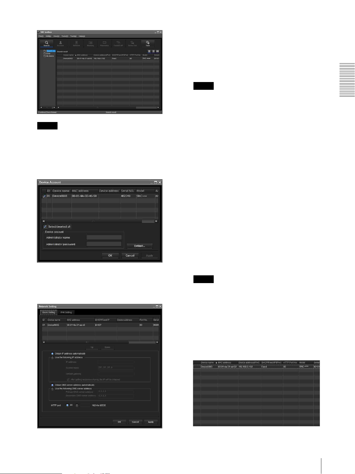
6
Click Search.
SNC toolbox detects the network cameras
connected to the local network and lists them.
6
Assigning the IP Address to the Camera
9
Set the IP address.
To obtain the IP address automatically from a
DHCP server:
Select Obtain an IP address automatically.
The IP address, Subnet mask and Default gateway
are assigned automatically.
Note
Tip
The factory setting of the camera network is DHCP
mode for both LAN and Wireless LAN.
7
Select a camera you want to assign an IP address
from the list and click Network.
The account settings screen is displayed.
When you select Obtain an IP address
automatically, make sure that the DHCP server is
operating on the network.
To specify the IP address manually:
Select Use the following IP address, and type the
IP address, Subnet mask and Default gateway in the
relevant boxes.
10
Set the DNS server address.
To obtain the DNS server addresses
automatically:
Select Obtain DNS server address automatically.
To specify the DNS server addresses manually:
Select Use the following DNS server address, and
type the Primary DNS server address and
Secondary DNS server address in the relevant
boxes.
11
Set the HTTP port No.
Normally, select 80 for the HTTP port No. To use
another port number, type a port number between
1024 and 65535 in the text box.
Preparation
8
Register the name and password of the
administrator and click OK.
The factory settings for both items are “admin”.
The Network Setting screen is displayed.
Note
When using a port number other than 80, check
with the network administrator first.
12
Confirm that all items are correctly set, then click
OK.
If “Setting OK” is displayed, the IP address is
correctly assigned.
13
When setting is finished, to access the camera
directly, double-click the camera name in the list.
Assigning the IP Address to the Camera
7
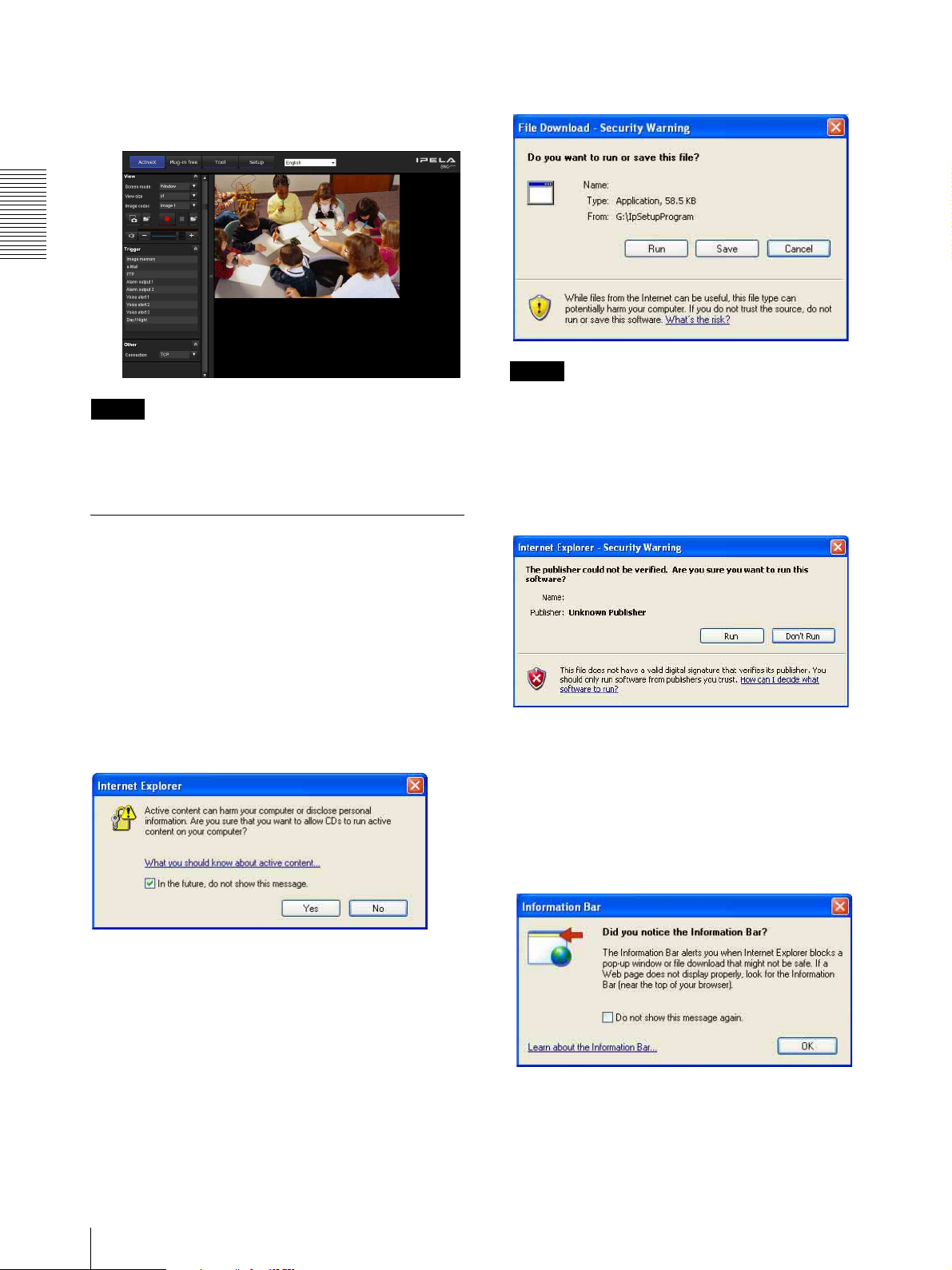
Preparation
The viewer screen of the network camera is
displayed on the Web browser.
Display sample
Note
If the IP address is not set correctly, the viewer does not
appear after step 13. In that case, try to set the IP address
again.
When using Windows XP Service
If the message “File Download – Security Warning”
appears, click Run.
Program name
Note
If you select Save in the “File Download – Security
Warning” dialog, you will not be able to perform the
installation correctly. Delete the downloaded file, and
click the Setup icon again.
If the message “Internet Explorer – Security Warning”
appears, click Run.
Pack 2 or later
Installing software
A warning message regarding the active contents may
appear when you install software such as SNC toolbox
from CD-ROM. In this case, operate as follows:
Example: In case of SNC toolbox
If message “Internet Explorer” appears, click Ye s .
Program name
The software installation starts.
Installing ActiveX Control
During installation of ActiveX Control, the
“Information Bar” or “Security Warning” may appear.
In this case, operate as follows:
If the message “Information Bar” appears, click OK.
8
Assigning the IP Address to the Camera

If the information bar appears, click on the bar and select
Install ActiveX Control….
If “ Internet Explorer – Security Warning” appears, click
Install.
Program name
The installation of ActiveX Control starts. When
installation is completed, the main viewer or the Motion
detection menu appears.
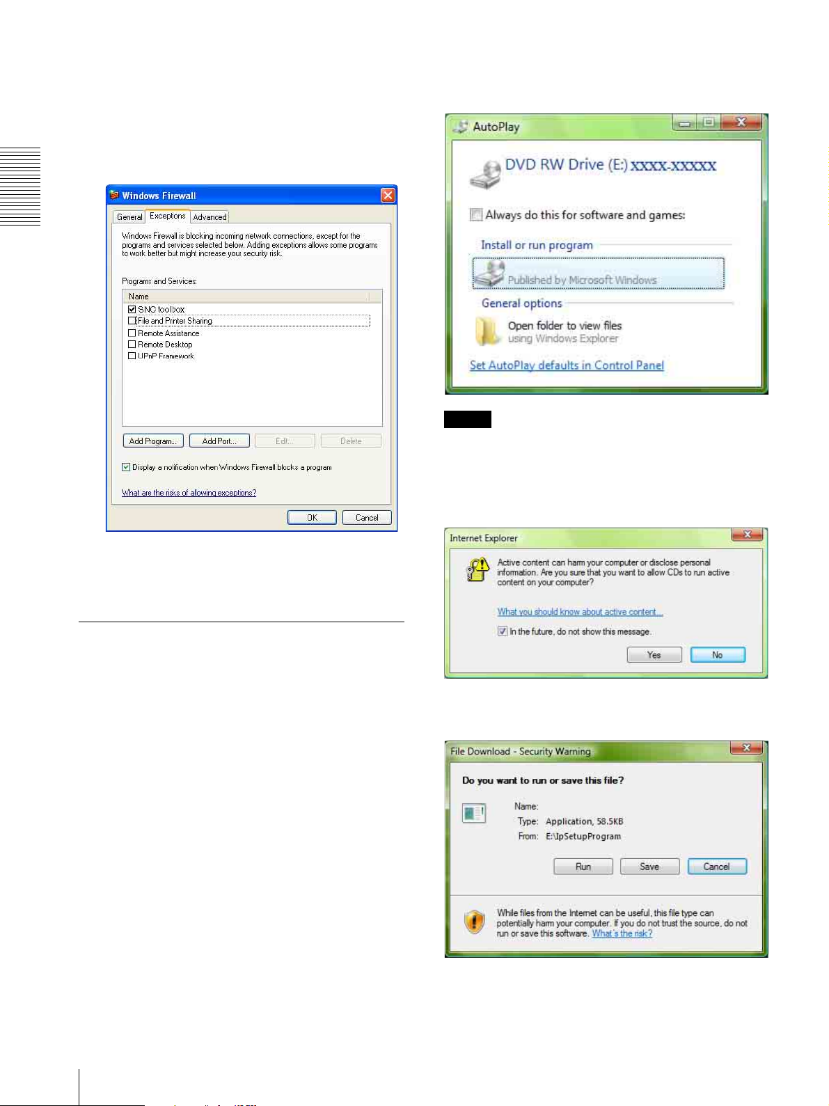
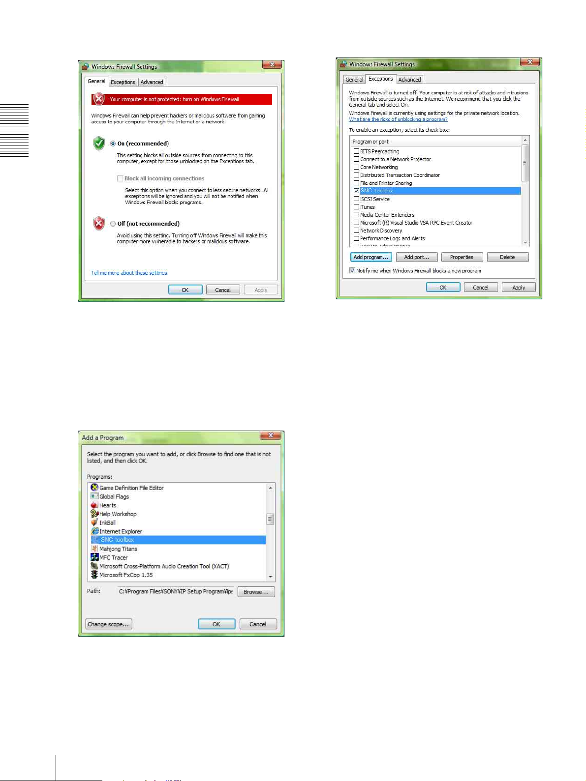
Configuring Windows Firewall
SNC toolbox or SNC audio upload tool may not operate
correctly depending on the configuration of Windows
Firewall. (No cameras are shown in the list even if they
are detected.) In this case, confirm the Windows
Firewall configuration as follows:
3
Select Off in the Windows Firewall dialog.
The camera will be displayed in the list.
If you want to keep Windows Firewall On, continue
with the following steps.
4
Select the Exceptions tab.
Preparation
Example: In case of SNC toolbox
1
Select Control Panel from the Start menu of
Windows.
2
Select Security Center of the working field.
5
Click Add Program….
Assigning the IP Address to the Camera
9
Preparation
6
In the Add Program dialog, select SNC toolbox and
click OK.
SNC toolbox is added to the Programs and Services
list.
7
Click OK.
If the pop-up “AutoPlay” appears when a CD-ROM is
inserted into the CD-ROM drive, click Install or run
program.
Program name
Note
If you click Open folder to view files, the Web browser
will not open automatically. In this case, double-click
the “index.htm” file in the CD-ROM.
When the above procedure is completed, the
camera connected in the local network are
displayed in SNC toolbox.
When using Windows Vista
Installing software
A warning message regarding the active contents may
appear when you install software such as SNC toolbox
from the CD-ROM. In this case, operate as follows:
Example: In case of SNC toolbox
If the message “Internet Explorer” appears, click Ye s .
If the message “File Download – Security Warning”
appears, click Run.
Program name
10
Assigning the IP Address to the Camera
Note
If you select Save in the “File Download – Security
Warning” dialog, you will not be able to perform
installation correctly. Delete the downloaded file, and
click the Setup icon again.
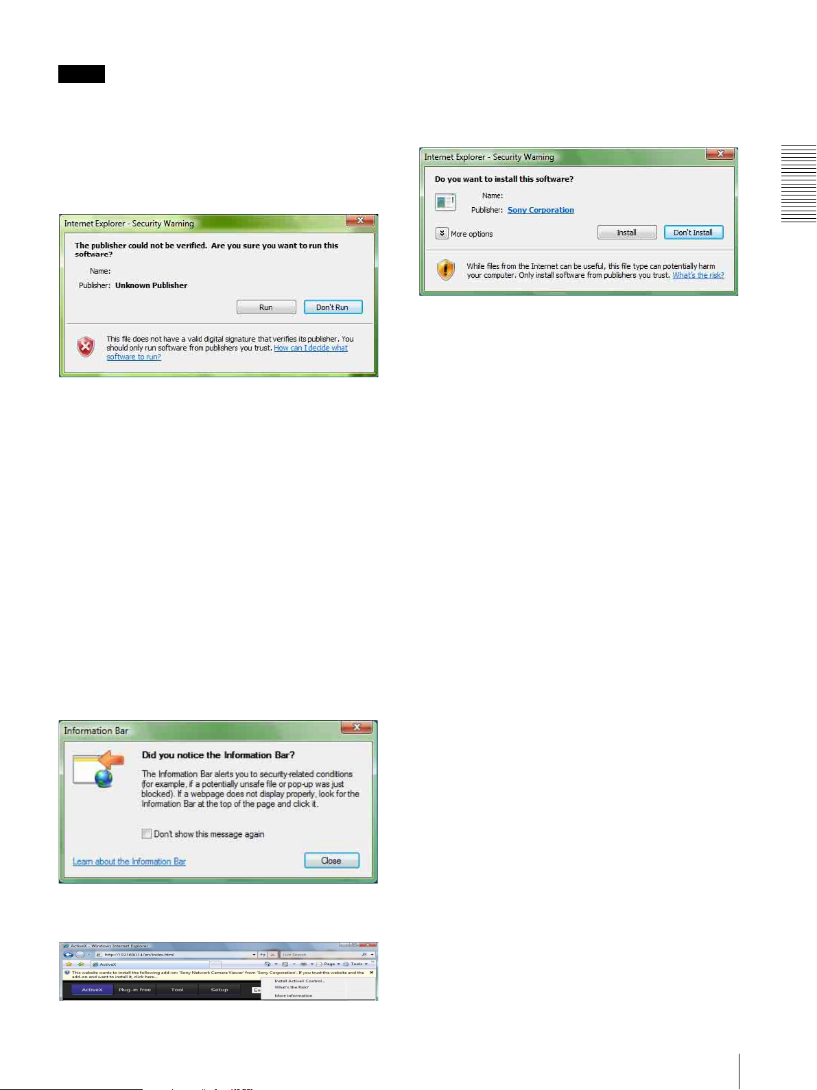
If the message “Internet Explorer – Security Warning”
appears, click Run.
Program name
If the message “User Account Control – An unidentified
program wants access to your computer” appears, click
Allow.
The software installation starts.
If the message “User Account Control – Windows needs
your permission to continue” appears, click Continue.
If “Internet Explorer – Security Warning” appears, click
Install.
Program name
Preparation
The installation of ActiveX Control starts. When
installation is completed, the main viewer or the Motion
detection menu appears.
Configuring Windows Firewall
SNC toolbox or SNC audio upload tool may not operate
correctly depending on the configuration of Windows
Firewall. (No cameras are shown in the list even if they
are detected.) In this case, confirm the Windows
Firewall configuration as follows:
Starting the software
When you start software such as SNC toolbox, the
message “User Account Control – An unidentified
program wants access to your computer” may appear. In
this case, click Allow.
Installing ActiveX Control
During installation of ActiveX Control, the information
bar or “Security Warning” may appear. In this case,
operate as follows:
If the message “Information Bar” appears, click Close.
Example: In the case of SNC toolbox
1
Select Control Panel from the Start menu of
Windows.
2
Click Windows Firewall.
3
Select Turn Windows Firewall on or off.
“User Account Control – Windows needs your
permission to continue” may appear. In this case,
click Continue.
If the information bar appears, click on the bar and select
Install ActiveX Control….
Assigning the IP Address to the Camera
11
Preparation
4
Select Off in the General tab.
8
Click OK.
The cameras will be displayed in the list.
If you want to keep Windows Firewall On, continue
with the following steps.
5
Select the Exceptions tab.
6
Click Add Program….
7
If the Add Program dialog appears, select SNC
toolbox and click OK.
When the above procedure is completed, the
cameras connected in the local network are
displayed in SNC toolbox.
SNC toolbox is added to the Program or port list.
12
Assigning the IP Address to the Camera
Accessing the Camera Using the Web Browser
After the IP address has been assigned to the camera,
check that you can actually access the camera using the
Web browser installed on your computer.
Use Internet Explorer as a Web browser.
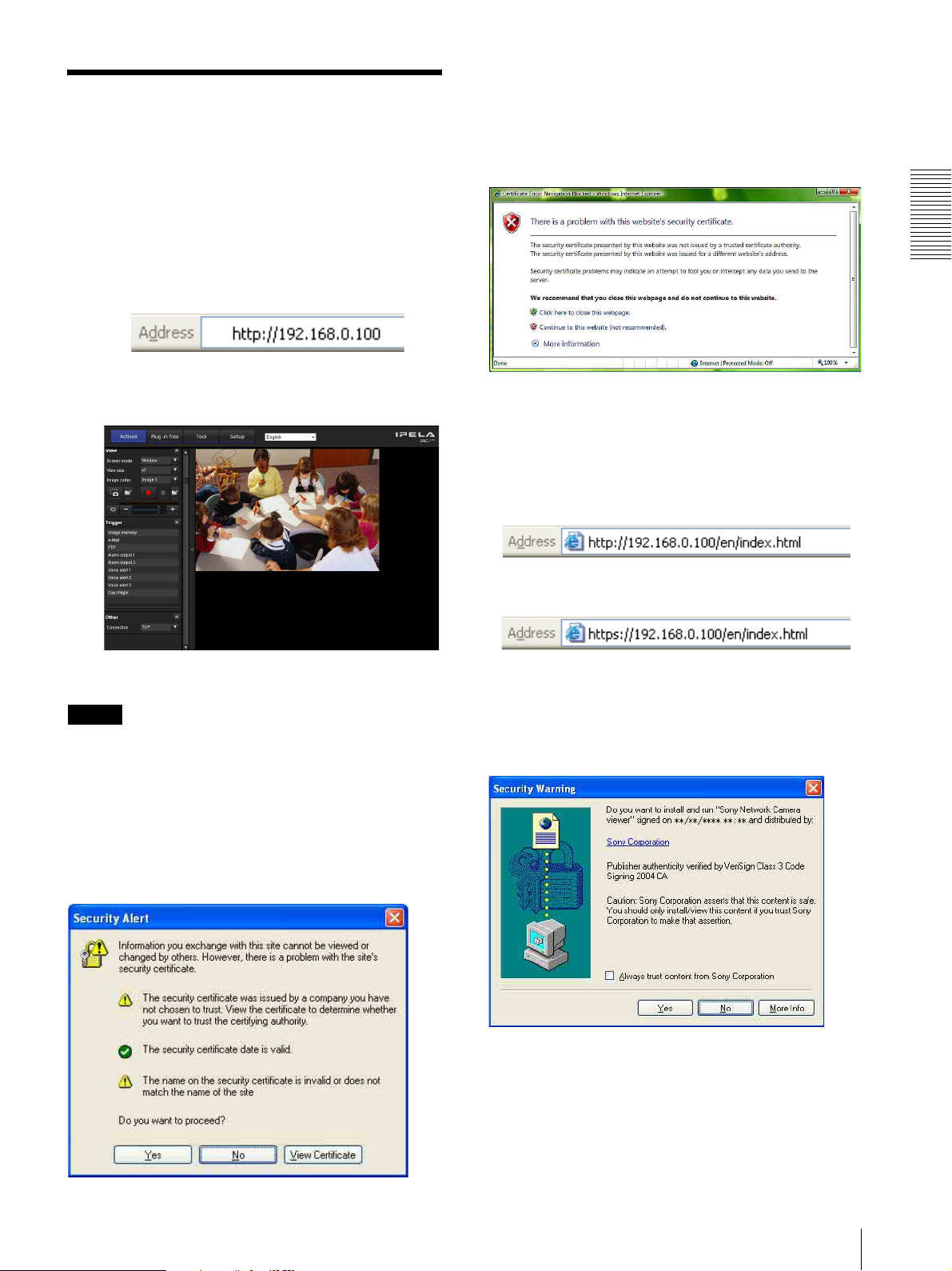
When Internet Explorer 7 is used
When you enter the camera IP address, “Certificate
Error” may appear according to the status of the
certificate set on the camera. In this case, click Continue
to this website (not recommended). to continue.
The welcome page appears (in SSL communication).
1
Start the Web browser on the computer and type the
IP address of the camera in the URL address bar.
The viewer window is displayed.
Display sample
Using the SSL function
Note
The model on sale in China does not support the SSL
function.
Preparation
When “Allow HTTP connection for some
clients” (page 46) is checked
To use HTTP and SSL connections separately to access,
enter the following in the address box of the browser.
For HTTP connection
For SSL connection
When the viewer of the camera is
displayed for the first time
“Security Warning” is displayed. When you click Ye s ,
ActiveX control is installed and the viewer is displayed.
When Internet Explorer 6 is used
“Security Alert” dialog may appear according to the
status of the certificate. In this case, click Ye s to
continue.
The viewer window is displayed (in SSL
communication).
Accessing the Camera Using the Web Browser
13

Preparation
Notes
• If Automatic configuration is enabled in the Local
Area Network (LAN) settings of Internet Explorer, the
image may not be displayed. In that case, disable
Automatic configuration and set the Proxy server
manually. For the setting of the Proxy server, consult
your network administrator.
• When you install ActiveX Control, you should be
logged in to the computer as Administrator.
• If you are using Windows XP Service Pack 2 or later,
or Windows Vista, the information bar or “Security
Warning” may appear. For details, see “Installing
ActiveX Control” in “When using Windows XP
Service Pack 2 or later” on page 8 or “Installing
ActiveX Control” in “When using Windows Vista” on
page 11.
Tip
The software is optimized for Internet Explorer using
medium font.
To display the viewer correctly
To operate the viewer correctly, set the security level of
Internet Explorer to Medium or lower, as follows:
1
Select Too ls from the menu bar for Internet
Explorer, then select Internet Options and click
the Security tab.
2
Click the Internet icon (when using the camera via
the Internet), or Local intranet icon (when using
the camera via a local network).
3
Set the slider to Medium or lower. (If the slider is
not displayed, click Default Level.)
When using antivirus software, etc., on
the computer
• When you use antivirus software, security software,
personal firewall or pop-up blocker on your computer,
the camera performance may be reduced, for example,
the frame rate for displaying the image may be lower.
• The Web page displayed when you log in to the
camera uses JavaScript. The display of the Web page
may be affected if you use antivirus software or other
software described above on your computer.
14
Accessing the Camera Using the Web Browser

Basic Configuration by the Administrator
You can monitor the camera image by logging in with
the initial conditions set for this network camera. You
can also set various functions according to the installing
position, network conditions or purpose of the camera.
We recommend you configure the following items
before monitoring images from the camera.
Setting contents Setting menu
Set the format of the image sent from the camera. Video codec Tab (page 36)
Select the White Balance mode according to the installation position. White balance (page 34)
Preparation
Select the brightness of the image sent from the camera. Exposure (page 33)
Select the quality of the image sent from the camera. Video codec Tab (page 36)
Select the view size of the image. View size (page 18)
Select whether the audio from the external microphone is sent or not. Microphone (page 31)
Synchronize the date and time of the camera with those of the computer. Date & time Tab (page 28)
Make the setting for sending the monitor image attached to an e-mail. e-Mail (SMTP) Menu (page 58)
Set the user access right for the camera. User Menu (page 57)
Brightness (page 34)
Basic Configuration by the Administrator
15

Operating the Camera
Administrator and User
This network camera identifies those who log in as the
This section explains how to monitor the image from the
camera using your Web browser (Internet Explorer).
Administrator or User.
The Administrator can use all the functions of this
network camera, including camera settings. The User
The functions of the camera should be set by the
Administrator. For the setting of the camera, see
“Administrating the Camera” on page 26.
can use the functions for monitoring the image and
audio from the camera, and control the camera. The
Viewer mode setting is used to restrict the user’s access
rights. There are three types of users.
Each type of user can use the corresponding functions below.
Operating the Camera
Function Administrator
Monitor a live image z zzz
View the date and time z zzz
Control the frame rate (JPEG mode only) zz––
Control the image view size zzz–
Save a still image and movie in the computer zzz–
Send an image file to the FTP server zz––
Send an image attached to an e-mail zz––
Record an image in the memory zz––
Control the alarm output of the I/O port on the camera zz––
Switch the Day/Night function mode zz––
Play an audio file (Voice alert) zz––
Switch the TCP/UDP transmission mode (Available in MPEG4/
H.264 mode only)
Receive audio z zzz
Select the codec mode zzz–
Control the setting menu z –––
zz––
Full Light View
User
z Usable function
– Not usable function
The access rights of the administrator and the user can
be set in “Setting the User — User Menu” of the
Administrator menu on page 57.
16
Administrator and User
Logging in to System
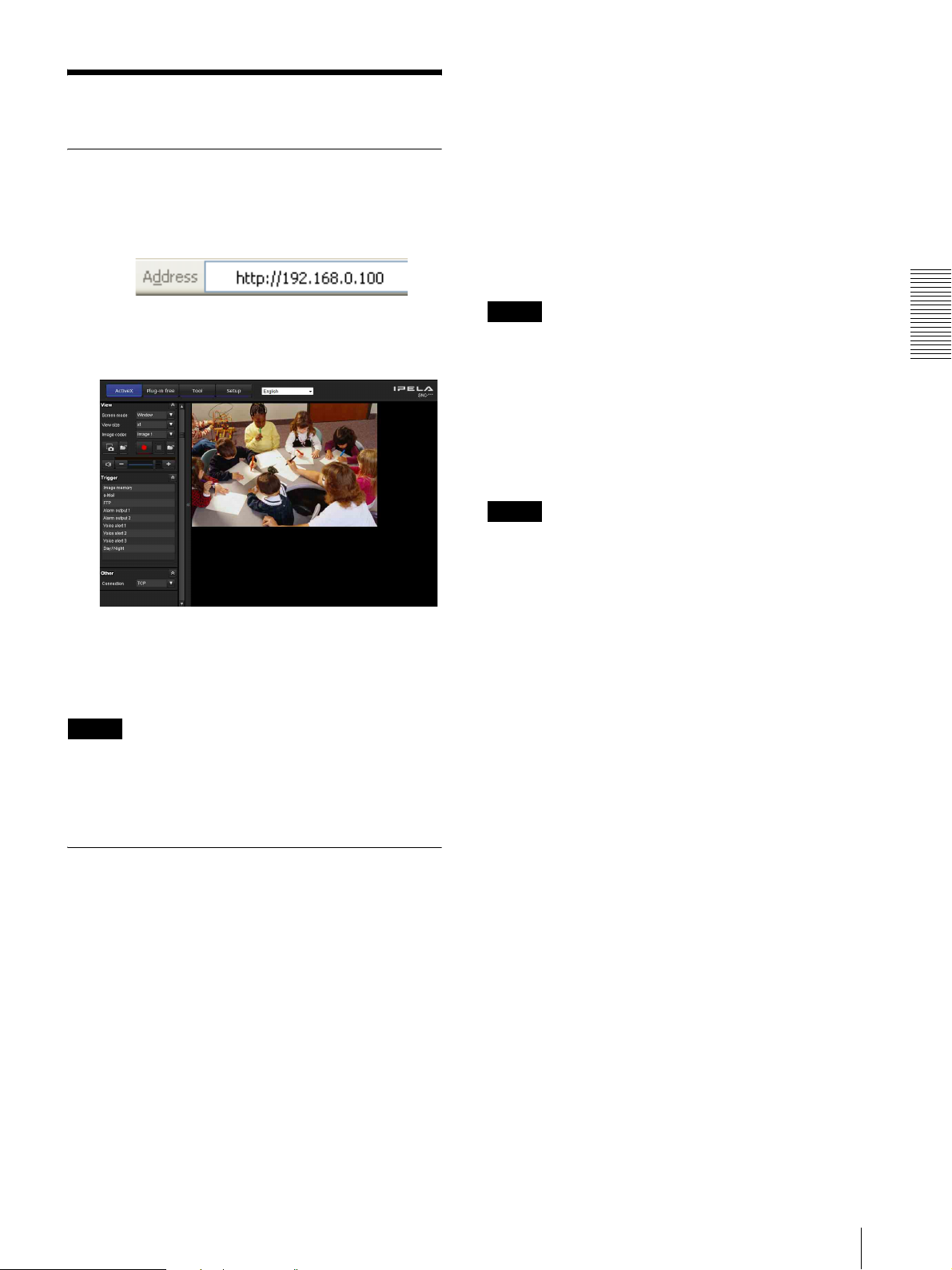
Logging in as a user
1
Start the Web browser on your computer and type
the IP address of the camera you want to monitor.
Plug-in free viewer
This viewer allows the user to select from three image
display methods: JPEG, JPEG/FLASH or ActiveX
viewer.
JPEG method: JPEG images will be displayed in
sequence.
JPEG/FLASH method: JPEG images will be displayed
in sequence. Adobe Flash is required to display the
image.
ActiveX viewer method: The image can be viewed when
the image display is set to JPEG, MPEG4 or H.264.
The viewer is displayed.
Display sample:
Three types of viewer are available: ActiveX
viewer, Plug-in free viewer and custom homepage.
By default, ActiveX viewer is displayed. To switch
the viewer, make changes to the Viewer menu
(page 79).
Note
If the main viewer does not start correctly, the security
level of the Internet Explorer may be set to higher than
Medium. See “To display the viewer correctly” on
page 14 and check the security level.
Notes
• If Automatic configuration is enabled in the Local
Area Network (LAN) Settings of Internet Explorer,
the camera image may not be displayed. In that case,
disable Automatic configuration and set the Proxy
server manually. For the setting of the Proxy server,
consult your network administrator.
• When you install ActiveX Control, you should be
logged in to the computer as the Administrator.
Tip
Every page of this software is optimized for Internet
Explorer in Medium font.
Operating the Camera
About Viewers
You can use the following viewers.
ActiveX viewer
This viewer can monitor the camera image in any of the
JPEG, MPEG4 and H.264 video codecs.
You must install this viewer when you access the main
viewer for the first time.
When you display the main viewer of the
camera for the first time
When you access the network camera using ActiveX
viewer for the first time, the Security Warning appears.
Click Ye s and install ActiveX Control. You can use all
the functions of the viewer with ActiveX Control.
Logging in to System
17
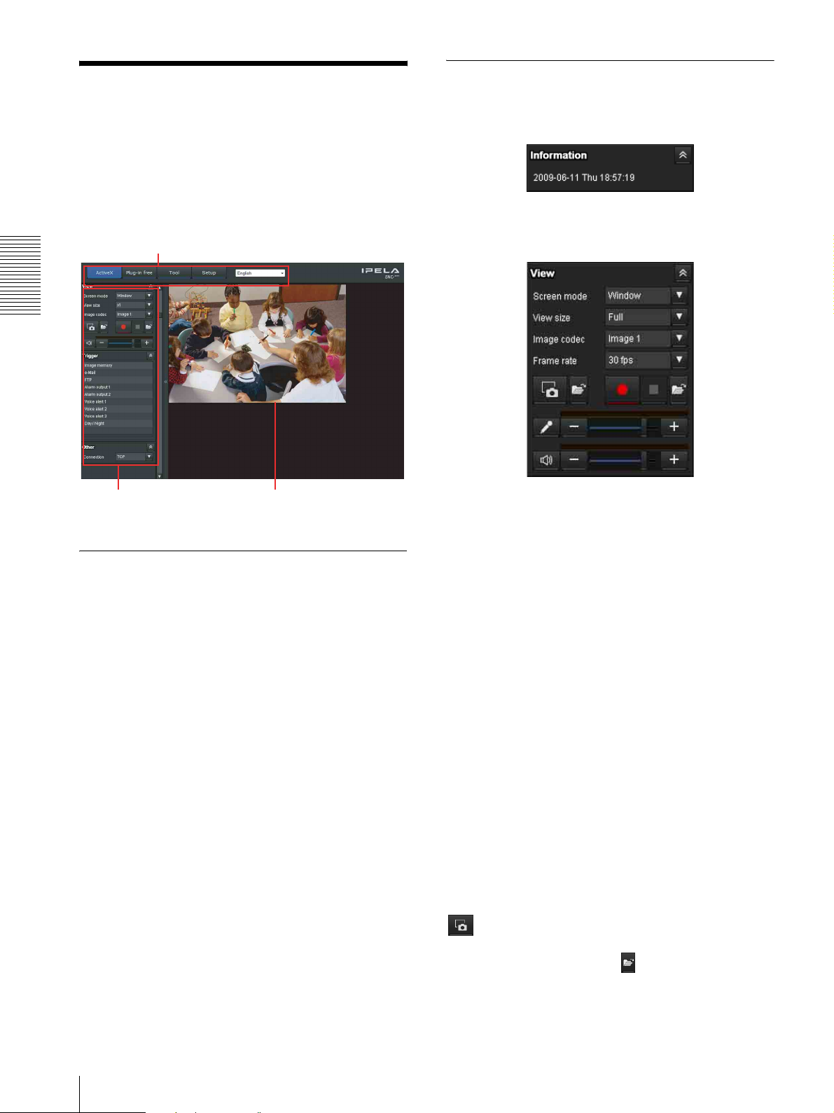
Configuration of Main
Control panel section
Viewer
This section explains the functions of the parts and
controls of the main viewer. For a detailed explanation
on each part or control, see the specified pages.
Main viewer using ActiveX viewer
Main menu
Operating the Camera
Control panel
section
Main menu
Monitor image
section
Information panel
Check the date and time here.
View panel
You can change the screen mode, size of the image,
image codec mode and frame rate. Also, still images and
movies can be saved (movie saving can also be stopped)
from here. Microphone and audio output levels can be
adjusted.
ActiveX
Displays the ActiveX viewer.
Plug-in free
Displays the Plug-in free viewer.
Tool
You can download system utility from here. (page 23)
This operation is only available when you are logged in
as administrator.
Setup
Click to display the Administrator menu. (page 26)
You can operate this function only when logging in as
the administrator.
Screen Mode
Select Window or Full Screen.
View size
Selects the view size to be displayed.
Click View size list box to select the view size.
Select x1 to display images set in Image size of the
Camera menu. (page 36)
Select Full to display images according to the view size.
Select Fit to display images according to the view size,
with fixed aspect ratio.
Image Codec
Select an image codec mode.
Frame rate
(Displayed only when the camera image is in JPEG.)
Selects the frame rate to transmit images.
(Capture)
Click to capture a still image shot by the camera and to
store it in the computer. Click to open the folder to be
saved.
18
Configuration of Main Viewer
(Run)/ (Stop Save Video)
Runs and stops Save Video. Click to open the folder
to be saved.
Volume
Use the slide bar to adjust the volume for sound output
level.
When you click , the icon changes to and the
output from the speaker stops. To output sound from the
speaker, click again.
Microphone volume
This is displayed when Microphone (page 31) in the
Common tab of the Camera menu is set to On, and a user
with audio enabled in the User Menu accesses the
device.
Use the slide bar to adjust the microphone volume.
When you click , the icon changes to and the
microphone input stops. To input the microphone, click
again.
Others panel
(Displayed only when the camera image is in MPEG4 or
H.264.)
You can switch between TCP and UDP (Unicast/
Multicast).
Each click switches the transmission mode of the video/
audio data between TCP mode, UDP (Unicast) mode,
and UDP (Multicast) mode (page 22).
Operating the Camera
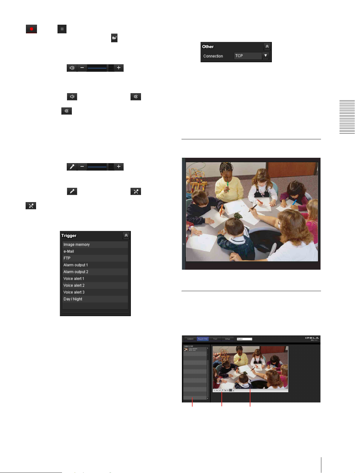
Monitor image
Trigger panel
The above is displayed only when Viewer mode
(page 57) is set to Full, and one or more triggers are
enabled in the Trigger menu (page 70).
The configured functions are displayed as buttons on
this panel.
Click the function button you want to use on the Trigger
panel. The selected function is activated. The selectable
functions are as follows:
• send still image files attached to an e-mail (page 21)
• send still image files to an FTP server (page 21)
• Record still image files (page 21)
• control the alarm output (page 21)
• switch the Day/Night function on/off (page 21)
• play the audio file stored in the camera (page 21)
The image shot by the camera is shown here.
Plug-in free viewer
Main viewer using Plug-in free viewer
Display sample:
Camera list
Control bar
Monitor screen
Configuration of Main Viewer
19

Monitor screen
(Pan/tilt/zoom functions are not available for this
model.)
The image shot by the camera is shown here.
There are two modes for on-screen pan/tilt/zoom
operation using a mouse: Area zoom mode and Vector
dragging mode. A control bar is displayed on the screen.
In the Area zoom mode, clicking will pan or tilt the
camera towards the center of the image. The Area zoom
will move the camera in the direction that displays the
area selected by the operator and zooms in at the same
time. The operator can choose a part of the image to
view and zoom in by surrounding the area with a frame
by dragging the mouse.
In the Vector dragging mode, the camera pans or tilts in
Operating the Camera
the dragged direction. How long you drag the mouse
determines the speed. Releasing the button on the mouse
after dragging stops the panning or tilting of the camera.
You can also use the tool bar to pan or tilt. The zoom
operation using the mouse wheel is available in all
modes.
Save still image button
Captures still images taken by the camera and saves
them to the computer.
Audio output volume slider
Use the slider to adjust the volume. Clicking the
button will stop sound output.
(Displayed only when ActiveX is set for
Streaming method in Setting, and Microphone
in the Camera Menu (page 31) is set to On.)
Control waiting time and control time for exclusive
control
Exclusive control button (Not available with this
product.)
Camera list
The camera list is displayed when Camera list is set to
On in the viewer menu, and at least one camera is
registered.
Control bar
The following operation buttons are available.
Setting
You can set the streaming method, image size,
frame rate, PTZ operation mode (Not available with
this product), and trigger selection.
Streaming start button
Starts streaming. (Appears while stops streaming.)
Streaming stop button
Stops streaming. (Appears while streaming.)
Trigger run button
Runs the selected trigger.
Preset (Not available with this product.)
Select a preset position to move the camera to the
registered preset position.
(Displayed only when a camera preset position is
registered.)
20
Configuration of Main Viewer

Using the Trigger Button
You can execute various functions by clicking their
respective buttons on the Trigger panel.
Sending a monitor image via e-mail
You can send a captured still image by attaching it to an
e-mail.
To use this function, you need to make e-Mail (SMTP)
active and set the address in the Trigger menu of the
Administrator menu properly (page 70).
1
Click e-Mail (SMTP) on the Trigger panel.
The still image of the moment you click is captured,
and your e-mail with the image file attached is sent
to the specified mail address.
Controlling Alarm out 1, 2
You can control Alarm out 1, 2.
To use this function, you need to make Alarm out 1 or
Alarm out 2 active in the Trigger menu of the
Administrator menu (page 71).
1
Click Alarm out 1 or Alarm out 2 on the Trigger
panel.
The alarm output is switched by clicking.
The alarm output mode can be selected from
To gg le or Timer of Alarm out 1, 2 in the Trigger
menu (page 71).
Tip
For the connection of peripheral devices to the alarm
output of the I/O port, see the supplied Installation
Manual.
Operating the Camera
Sending a monitor image to an FTP server
You can send a captured still image to the FTP server.
To use this function, you need to make FTP active and
set the address in the Trigger menu of the Administrator
menu properly (page 71).
1
Click FTP client on the Trigger panel.
The still image of the moment you click is captured,
and the image file is sent to the FTP server.
Recording a camera image as a still image
You can capture a camera image as a still picture and
record it.
SNC-CH140 can record images in its built-in memory or
CF memory card (not supplied). SNC-DH140 can only
record images in its built-in memory.
To use this function, you need to make Image memory
active and set the details in the Trigger menu of the
Administrator menu (page 71).
1
Click Image memory on the Trigger panel.
The still image of the moment you click is captured,
and the image file is recorded.
Controlling the Day/Night function
You can set the Day/Night function to On (night mode)
and Off (day mode).
To use this function, you need to make Day/Night active
in the Trigger menu of the Administrator menu
(page 71).
1
Click Day/Night on the Trigger panel.
Each click switches the Day/Night function
alternately between On (night mode) and Off (day
mode).
Note
If Day/Night in the Trigger-Day/Night menu (page 71)
is set to Auto, you cannot control the Day/Night
function by clicking Day/Night.
Playing an audio file stored in the camera
You can play an audio file previously stored in the
camera using the SNC audio upload tool.
To use this function, you need to make Voice alert1,
Voice alert2 and Voice alert3 active in the Trigger menu
of the Administrator menu (page 71).
1
Click Voice alert1, Voice alert2 or Vo i ce al e rt 3 on
the Trigger panel.
Playback of the selected audio file starts and the
playback sound is output from the speaker
connected to the camera.
Using the Trigger Button
21
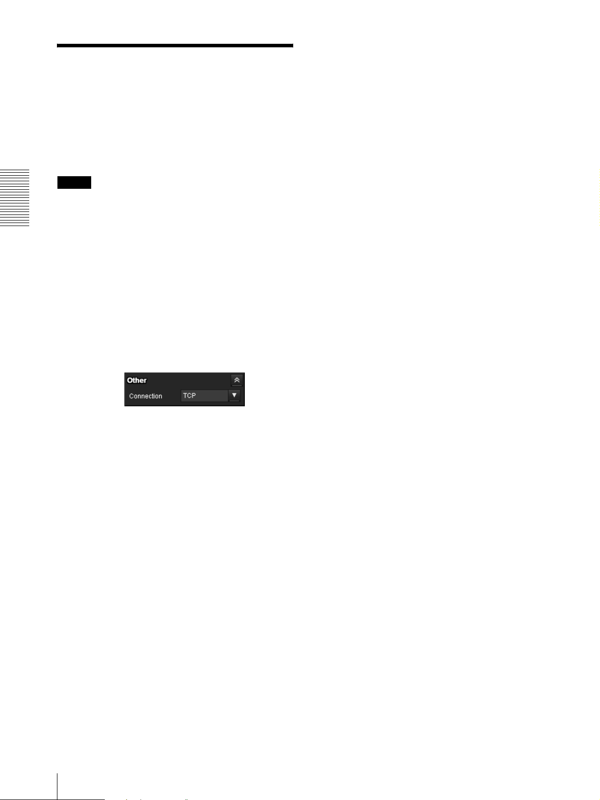
UDP (Multicast): This protocol is selectable when
Switching TCP/UDP Transmission Mode
You can select TCP or UDP as the communication port
for video/audio data.
This function can be used when Mode (video codec
mode) is set to MPEG4 or H.264 and the ActiveX
viewer is used.
Notes
• The function may not operate correctly if you use
personal firewall software or antivirus software on
Operating the Camera
your computer. In that case, disable the software or
select the TCP mode.
• If you are using Windows XP Service Pack 2 or later,
or Windows Vista, disable “Windows Firewall.” For
details, see “Configuring Windows Firewall” in
“When using Windows XP Service Pack 2 or later” on
page 9, or “Configuring Windows Firewall” in “When
using Windows Vista” on page 11.
1
Select TCP, UDP (Unicast) or UDP (Multicast)
from the Connection drop-down list in the Others
panel.
Multicast streaming (page 38) is On. When UDP
(Multicast) is selected as the transmission port,
RTP (Real-time Transport Protocol) and UDP
multicast techniques are adopted for video/audio
transmission. By selecting it, the network
transmission load of the camera can be reduced. If
a router that does not correspond to a multicast or
firewall is installed between the camera and the
computer, video/audio may not play back properly.
In this case, select TCP or UDP (Unicast).
TCP: This is normally selected.
When TCP is selected as the communication port,
HTTP communication is adopted for video/audio
communications.
HTTP is the protocol used for reading the usual
Web page.
In an environment capable of reading Web pages,
you can watch or listen to video/audio by selecting
the TCP port.
UDP (Unicast): When UDP (Unicast) is selected
as the communication port, RTP (Real-time
Transport Protocol) is adopted for video/audio
communications. Since RTP is the protocol for
running video/audio data, the video/audio playback
is smoother than when TCP (HTTP) is selected. If
a firewall is installed between the camera and the
computer, or depending on the network
environment, video/audio may not play back
properly when UDP (Unicast) is selected. In this
case, select TCP.
22
Switching TCP/UDP Transmission Mode
Using the System Utility
You can download system utility from the tools tab on
the main menu.
To use the utility, click Download to begin download.
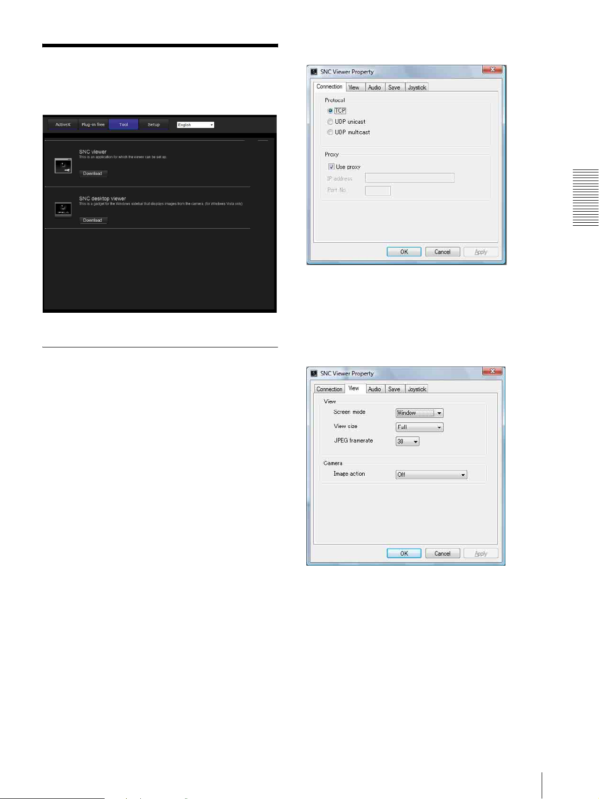
Connection tab
Operating the Camera
You can set the connection method.
Select the start-up connection from: TCP, UDP
Unicast, and UDP Multicast.
If TCP connection is selected, you can configure proxy
settings by selecting Use proxy.
SNC viewer
SNC viewer is an application which allows you to set the
initial state of the viewer.
Installing the SNC viewer
1
Execute the downloaded SNCViewer.msi file.
2
Install the SNC viewer following the instructions
on the wizard.
When the license agreement policies are displayed,
agree after reading them carefully and install the
SNC viewer.
Using the SNC viewer
Click SNC viewer in the control panel.
View tab
Screen mode
You can select Window or Full.
View size
You can select the view size.
JPEG framerate
You can set the frame rate for JPEG.
Image action
Select from the image operation modes Area zoom,
Vector dragging and Off.
Using the System Utility
23
Tip
This device is not equipped with operational functions
for images.
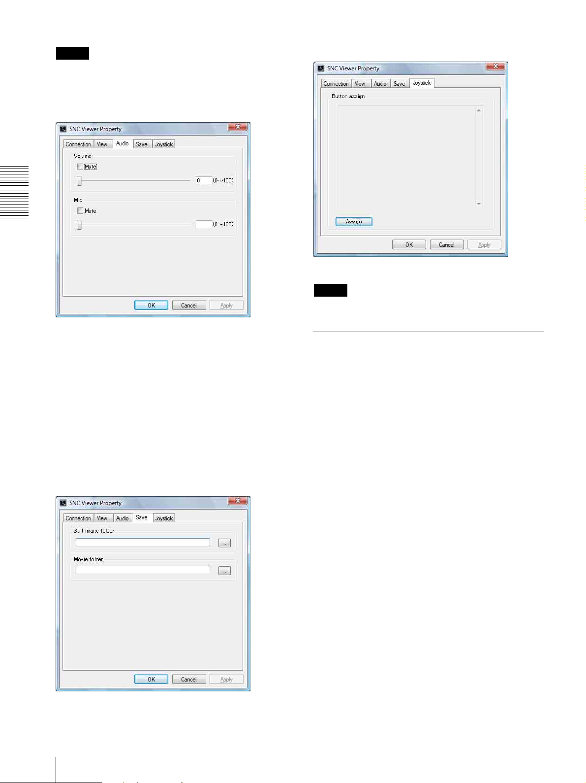
Joystick tab
Audio tab
Operating the Camera
You can assign the joystick buttons here.
Tip
This device is not equipped with Joystick functions.
Volume
Mute: Select this option for muting the sound at
start-up.
Use the slide bar to set the volume for start-up sound
output.
Mic
Mute: Select this option for muting the microphone
sound at start-up.
Use the slide bar to set the volume for start-up
microphone input.
Save tab
SNC Desktop viewer
This is a gadget that displays the camera image in the
side bar of Windows Vista.
Installing the SNC desktop viewer
1
Click Download.
When the license agreement policies are displayed
on the SNC desktop viewer download screen, agree
after reading them carefully and download the SNC
desktop viewer.
2
Execute the downloaded SncDesktopViewer.gadjet
file.
Specify a folder to save the still images and movies to.
24
Using the System Utility
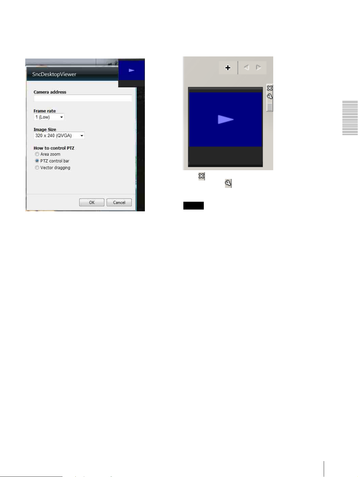
Using the SNC desktop viewer
When the SNC desktop viewer is successfully installed,
it will appear on the side bar of Windows Vista.
How to control PTZ
Select the PTZ operation mode for the Gadget screen
from the options Area zoom, PTZ control bar, and
Vector dragging.
Operating the Camera
Click (Exit) to exit Gadget.
When you click (Set), you will see the following
setting screen.
Camera address
Set the IP address for the camera to display on the
Gadget.
Frame rate
Select the frame rate for the image to display on the
Gadget.
Image size
Select the image size for the image to display on the
Gadget.
Tip
This device is not equipped with operational functions
for PTZ.
Using the System Utility
25
Administrating the Camera
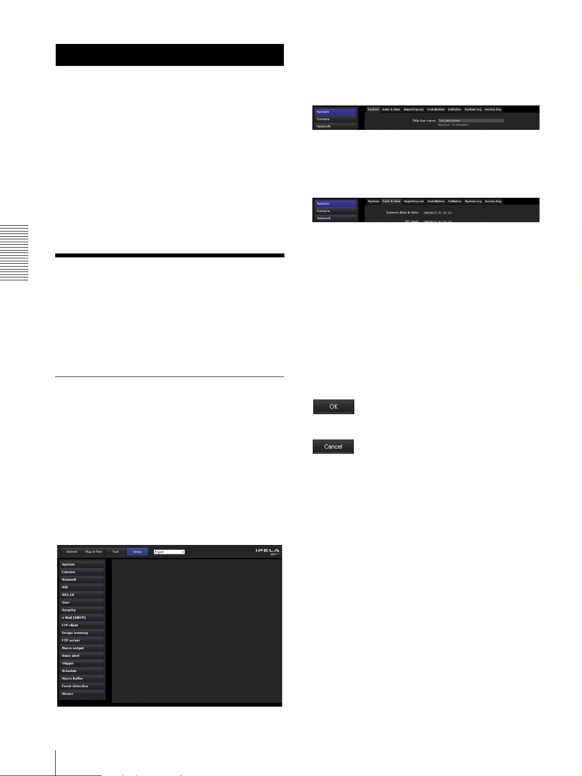
3
Click the menu name (example: System) on the left
side of the Administrator menu.
The clicked menu appears.
This section explains how to set the functions of the
camera by the Administrator.
For details about monitoring the camera image, see
“Operating the Camera” on page 16.
This section explains the basic operations and each
option of the Administrator menu.
Note on the display of menu options
The setting menus of this unit will clearly display only
the setting options that you can currently select. Grayed
out options cannot be selected.
Basic Operations of the
Administrating the Camera
Example: “System” menu
4
Select the required tab above the menu, and set each
setting option in the tab.
Example: “Date & time” tab of “System” menu
See pages 28 to 81 for details of the menu tabs and
setting options.
5
After setting, click OK.
The settings you have made become active.
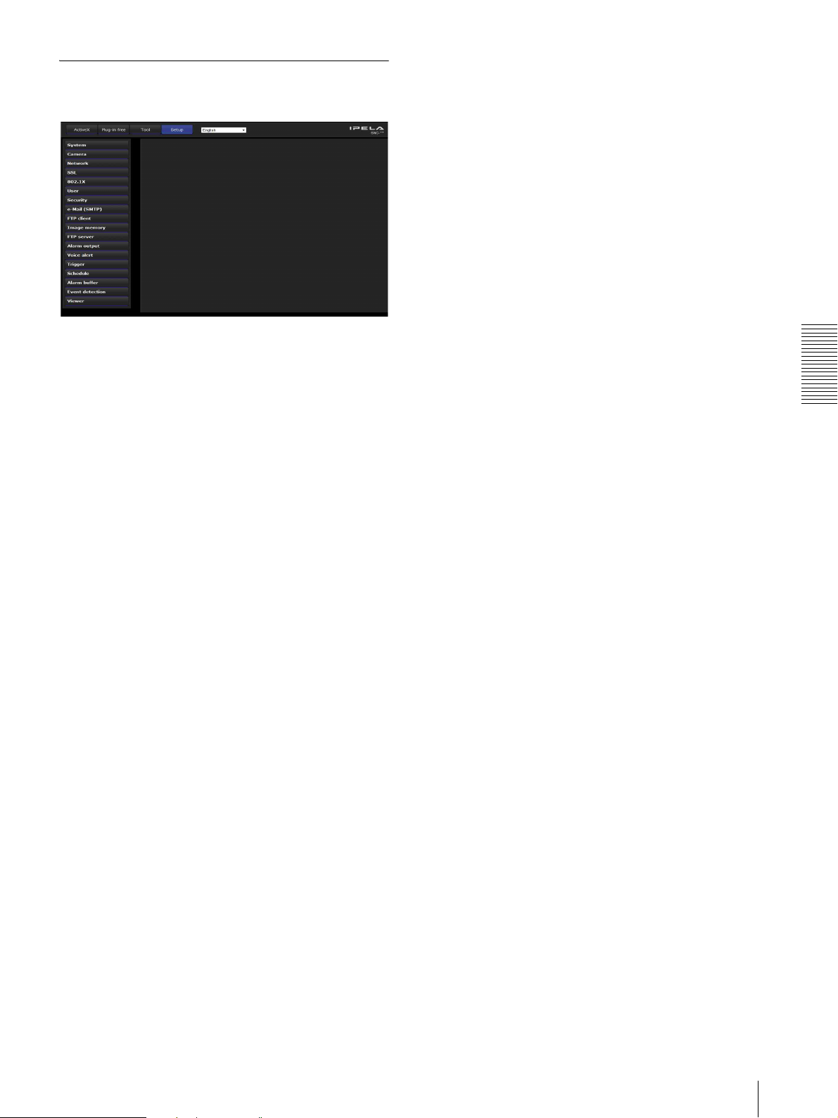
Administrator Menu
Click Cancel to nullify the set values and return to
You can use the Administrator menu to set all functions
to suit the user’s needs.
Click Setting in the viewer to display the Administrator
menu.
How to set up the Administrator
the previous settings.
Buttons common to every menu
The following buttons are displayed on all the menus.
The functions of the buttons are the same on every
menu.
menu
1
Log in to the homepage to display the viewer.
For details, see “Logging in as a user” on page 17.
2
Click Setting on the main menu.
The authentication dialog appears. Enter the user
name and password for Administrator.
The user name “admin” and password “admin” are
set at the factory for the Administrator.
The Administrator menu appears.
Click this button to confirm the settings.
Click this button to nullify the set values and return to
the previous settings.
General notes on menus
• One-byte katakana character is not valid for any text
field, such as User name.
• After changing a setting on a menu, wait at least 10
seconds before turning off the power of the camera.
If the power is turned off immediately, the new setting
may not be stored correctly.
• If the camera settings are changed while watching the
main viewer, some settings cannot be restored. To
reflect the change on the opening main viewer, click
Refresh on the Web browser.
26
Basic Operations of the Administrator Menu
Configuration of the Administrator menu
System
Displays the System menu. For details, see
“Configuring the System — System Menu” (page 28).
FTP client
Displays the FTP client menu for sending an image/
audio file, etc., to an FTP server. (“Sending Images to
FTP Server — FTP client Menu” on page 61)
Image memory
Displays the Image memory menu for recording an
image/audio file, etc. (“Recording Images in Memory
— Image memory Menu” on page 64)
FTP server
Displays the FTP server menu for setting the FTP server
function of the camera. (“Downloading Images from the
Camera — FTP server Menu” on page 68)
Alarm output
Displays the Alarm output menu for setting the alarm
output terminal of the camera. (“Setting the Alarm
Output — Alarm output Menu” on page 68)
Camera
Displays the Camera menu for setting the camera image
and audio. For details, see “Setting the Camera Image
and Audio — Camera Menu” (page 31).
Network
Displays the Network menu for setting the network
connection. For details, see “Configuring the Network
— Network Menu” (page 38).
SSL
Displays the SSL menu for performing SSL
communication between the client device and camera.
(“Setting the SSL function — SSL Menu” on page 46)
802.1X
Displays the 802.1X menu for connecting the camera to
a network configured in compliance with the 802.1X
standard for port authentication. (“Using the 802.1X
Authentication Function — 802.1X Menu” on page 51)
User
Displays the User menu for setting the log in user name
and password. (“Setting the User — User Menu” on
page 57)
Voice alert
Displays the Voice alert menu for playing an audio file
stored in the camera in synchronization with alarm
detection by the sensor input or the motion detection
function. (“Outputting Audio Linked to Alarm
Detection — Voice alert Menu” on page 69)
Trigg er
Displays the Trigger menu for designating the operation
to execute when you run a trigger. (“Setting the
Operations from the Viewer — Trigger Menu” on page
70)
Schedule
Displays the Schedule menu for the Day/Night function,
e-Mail (SMTP) function, FTP client function, Image
memory function and Alarm output function, Voice alert
function, etc. (“Setting the Schedule — Schedule Menu”
on page 72)
Alarm buffer
Displays the Alarm buffer menu for the buffer for
storing the image and audio related to alarm detection.
(“Setting the Alarm Buffer — Alarm buffer Menu” on
page 72)
Administrating the Camera
Security
Displays the Security menu for specifying a computer
that is allowed to connect to the camera. (“Setting the
Security — Security Menu” on page 58)
e-Mail (SMTP)
Displays the e-Mail (SMTP) menu for sending an email. (“Sending an Image via E-mail — e-Mail (SMTP)
Menu” on page 58)
Event Detection
Displays the setting menu for all built-in detection
functions. (“Setting the Sensor input/Camera tampering
detection/Motion detection — Event detection Menu”
on page 73)
Viewer
Displays the Viewer menu from which you can select the
viewer to use and configure advanced settings.
(“Configuring the Viewer — Viewer Menu” on page 79)
Basic Operations of the Administrator Menu
27

Date & time format
Configuring the System
— System Menu
When you click in the Administrator menu,
the System menu appears.
Use this menu to perform the principal settings of the
software.
The System menu has seven tabs: System, Date & time,
Superimpose, Installation, Initialize, System log and
Access log.
System Tab
Title bar name
Type a name of up to 48 characters to be displayed on the
title bar. The characters typed here are displayed on the
title bar of the Web browser.
Administrating the Camera
Serial number
The serial number of the camera is displayed.
Software version
The software version of this camera is displayed.
System
Select the format of date and time to be displayed in the
main viewer from the drop-down list.
You can select the format between yyyy-mm-dd
hh:mm:ss (year-month-day hour:minutes:seconds),
mm-dd-yyyy hh:mm:ss (month-day-year
hour:minutes:seconds), and dd-mm-yyyy hh:mm:ss
(day-month-year hour:minutes:seconds).
Adjust
Select how to set the day and time.
Keep current setting: Select if you do not need to set
the date and time.
Synchronize with PC: Select if you want to
synchronize the camera’s date and time with the
computer.
Manual setting: Select if you want to set the camera’s
date and time manually.
Select the year, month, date, hour, minutes and
seconds from each drop-down list.
Synchronize with NTP: Select if you want to
synchronize the camera’s date and time with those of
the time server called NTP server (Network Time
Protocol).
Set the NTP server when Synchronize with NTP is
selected.
OK/Cancel
See “Buttons common to every menu” on page 26.
Date & time Tab
Current date & time
Displays the date and time set on the camera.
Note
After you have purchased the camera, be sure to check
the date and time of the camera and set as necessary.
PC clock
Displays the date and time set on your computer.
Use the following NTP server address: Synchronize
with the selected NTP server address.
NTP server 1: Enter the first choice for NTP server
address.
NTP server 2: Enter the second choice for NTP
server address.
NTP server 3: Enter the third choice for NTP server
address.
DHCP server: Select DHCP server when you need to
get NTP server information from DHCP server.
Multicast: Select Multicast when you search for an
NTP server with Multicast.
Time zone
Set the time difference from Greenwich Mean Time in
the area where the camera is installed.
Select the time zone in the area where the camera is
installed from the drop-down list.
Automatically adjust the clock for daylight
saving time changes
When selected, the clock is automatically adjusted
according to the daylight saving time of the selected
time zone.
Note
If the time zone selected in Time zone is different from
that set on the computer, the time is adjusted using the
time zone difference and set on the camera.
28
Configuring the System — System Menu

OK/Cancel
See “Buttons common to every menu” on page 26.
Superimpose Tab
Select whether to superimpose the camera ID, date &
time and other information on the image or not.
The camera ID is also superimposed on images recorded
by the Pre-alarm or Post-alarm function.
Superimpose
On/Off
When using the Superimpose function, select On.
Font size
Set the font size.
Superimpose format
Click Edit to edit the content to superimpose over each
display position.
Only one Date and one Camera ID can be specified for
the Superimpose format.
You can set the content to superimpose in the bottom
left, bottom right, top left, top right, center, top middle,
and bottom middle parts, respectively. However, if you
specify the top middle, superimposed content will not
appear on the top left or top right. Similarly, if you
specify bottom middle, superimposed content will not
appear on the bottom left or bottom right.
Click Date & Time, Camera ID, Codec or Event to
insert the corresponding tag into the string.
OK/Cancel
See “Buttons common to every menu” on page 26.
Style
Set the items to superimpose and the format to display
in. Superimpose settings are available for the following
items:
• Date: Set the display settings for date and time.
• Camera ID: Set the display settings for Camera ID
and string.
• Event: Configure the display setting for when an
event occurs.
• Codec: Configure the bit rate and frame rate display
settings. Displays the codec information for Image 1.
• Custom string: Set Custom string to display the text
of your choice.
Display format, including color, can be individually set
for each item.
Color: Select the font color of the superimposed text.
Blink: Select On to enable blinking for the
superimposed text. However, the blinking display is
not available for Date.
String Effect: Enable a string effect for displayed text.
Advanced: Click the Setting button in Date to
configure the format of date/time and the separator.
Click the Setting button in Camera ID to configure
the Camera ID string setting and upload Logo.
Images that can be used as a Logo must be in gif89a
format with an image size up to 640 × 120. The
number of pixels horizontally is even numbered and
the maximum file size is approximately 50 KB. The
Camera ID string and logo can not be used at the
same time.
Installation Tab
You can perform settings related to installation.
Maximum image size
1280 × 720: Image will have an aspect ratio of 16:9, and
an image size up to 1280 × 720 can be specified for
the video codec.
1280 × 1024: Image will have an aspect ratio of 5:4, and
an image size up to 1280 × 1024 can be specified for
the video codec.
Notes
• The camera restarts when the Maximum image size is
changed. It takes about 2 minutes.
• The settings below are changed when the Maximum
image size is changed.
– Camera menu-privacy mask tab: returns to the
factory setting.
– Camera menu-video codec tab: returns to the factory
setting except:
– Image size of image1: to be 1280 × 720 when set
to 1280 × 720, or 1280 × 1024 when set to
1280 × 1024.
– Frame rate of image1: to be 30fps when set to
1280 × 720, or 20fps when set to 1280 × 1024
– Alarm buffer menu: returns to the factory setting.
– Event detection menu- motion detection tab: returns
to the factory setting except:
– Maximum detection size of motion diction: to be
width of 1280 and height of 720 when set to
1280 × 720, or 1280 and height of 1024 when set
to 1280 × 1024.
Administrating the Camera
Configuring the System — System Menu
29

– Maximum detection size of VMF: to be width of
1280 and height of 720 when set to 1280 × 720 or
1280 and height of 1024 when set to 1280 × 1024.
Video out
You can configure the output setting for the analog
image output terminal of the camera. Select On to
output an NTSC or PAL signal.
Note
The output signal format is determined according to the
setting of the camera’s NTSC/PAL switch.
OK/Cancel
See “Buttons common to every menu” on page 26.
Initialize Tab
Restore setting
Loads the stored setting data of the camera.
Click Browse and select the file in which the setting data
is stored. Click OK, and the camera is adjusted
according to the loaded data, and restarted.
Notes
•With Restore setting, some items in the Network
menu (page 38) cannot be restored.
• The following items cannot be stored or restored with
Backup setting data or Restore setting.
– audio files uploaded using SNC audio upload tool
– a homepage created using Custom Homepage of
SNC toolbox
– a client certificate and CA certificate to be used in
the 802.1X authentication function
– Header logo
– superimpose logo
Administrating the Camera
Reboot
Used when rebooting the system.
Click Reboot, and the message “This System will be
rebooted. Are you sure?” appears. Click OK to reboot
the camera. It takes about two minutes to restart.
Factory default
Resets the camera to the factory settings.
Retain current network settings
When this item is checked, only the current network
settings will be retained after reset.
Click Factory default, and the message “Setup data will
be initialized. Are you sure?” appears. When you click
OK, the network indicator on the camera starts to blink.
After adjustments of the default settings have finished,
the camera reboots automatically. Do not turn off the
camera until the camera reboots.
Tip
The camera can also be reset to the factory settings by
turning on the power of this unit while pressing the reset
button on the camera. For details, see the supplied
Installation Manual.
Backup setting data
Saves the setting data of the camera in a file.
Click Save, and follow the instructions on the Web
browser to specify the folder and save the setting data of
the camera. The file name preset at the factory is “sncch140.cfg” for SNC-CH140.
Format CF memory card (SNC-CH140
only)
Click Format to format the CF memory card (not
supplied) inserted into the CF card slot of the camera.
The files and folders stored in the CF memory card are
deleted while formatting.
Notes
• Before formatting, disable the image memory
function and FTP server function to protect the CF
memory card from writing.
• Do not activate the Format CF memory card
function when no card is inserted into the CF card slot.
Delete custom homepage
Click Delete to delete the homepages recorded in the
flash memory of the camera with Custom Homepage of
SNC toolbox (page 88).
Delete voice alert file
Click Delete to delete all the audio files stored in the
camera using SNC audio upload tool (page 93).
Notes
• Clicking Delete deletes all the stored audio files
simultaneously. To delete a specified audio file only,
perform deletion of the audio file in the corresponding
Voice alert tab of the Voice alert menu (page 69).
• Before deleting the audio file, set Voice alert to Off in
each tab of the Voice alert menu (page 69).
Delete header logo
Click Delete to delete the header logo set in the Viewer
menu.
30
Configuring the System — System Menu
 Loading...