

Sony Ipela RM-NS1000 User Manual

4-160-013-11 (2)
System Controller
User’s Guide
Before operating the unit, please read this manual thoroughly
and retain it for future reference.
RM-NS1000
© 2009 Sony Corporation

Table of Contents
Chapter 1 Introduction
Function Overview...........................................................................5
Precautions and Limitations...........................................................7
Supported Systems .........................................................................7
Names of Parts.................................................................................8
Control Panel......................................................................................... 8
Left Side .............................................................................................. 10
Rear ..................................................................................................... 11
Bottom ................................................................................................. 11
Chapter 2 Operations in RM-NS1000 Mode
Overview.........................................................................................12
Logging On to the System ............................................................12
Viewing and Using the LCD ..........................................................14
Viewing the LCD ................................................................................ 14
Operating the Multi Function Menu.................................................... 14
Switching Modes ...........................................................................15
Operations in the Main Screen.....................................................16
Selecting a Monitor Frame............................................................18
Selecting a Camera........................................................................19
Assigning Cameras to Monitoring Frames .................................19
Switching between Monitoring Live Images and Playing
Recorded Images ....................................................................20
Setting the Joystick to Mouse Mode............................................21
Controlling Cameras .....................................................................21
Performing Pan, Tilt, and Zoom Operations ....................................... 21
Returning All Cameras to Preset Position 1........................................ 22
Using the Digital Zoom....................................................................... 22
Using Manual Focus............................................................................ 23
Using Auto Focus................................................................................ 23
Adjusting the Brightness of Images .................................................... 23
Setting Image Brightness Adjustment to Auto Mode ......................... 23
Using Camera Presets...................................................................24
Moving a Camera to a Preset Position ................................................ 24
Setting a New Preset Position ............................................................. 24
Performing a Camera Tour ...........................................................25
Performing Camera Tours ................................................................... 25
Performing Shadow Tours................................................................... 26
2
Table of Contents

Performing a Layout Tour.............................................................27
Outputting Audio to the Camera ..................................................28
Recording, Searching for, and Playing Back Images.................29
Recording Live Images ....................................................................... 29
Using the Jog/Shuttle Dial................................................................... 30
Playing Back Recorded Images........................................................... 31
Operations in the Search Screen.......................................................... 35
Searching for Recorded Images .......................................................... 36
Playing Back Recorded Images from Search Results ......................... 38
Exporting Recorded Images .........................................................38
Exporting Recorded Images ................................................................ 38
Exporting Recorded Images as Still Images........................................ 41
Locking Operation .........................................................................41
To Lock Operation .............................................................................. 41
To Unlock the Lock............................................................................. 42
Setting the System Controller to the Off State ...........................42
Adjusting the Brightness of the LCD...........................................43
Adjusting the Brightness and Contrast................................................ 43
Turning On/Off the code number indication....................................... 43
Multi Function Menu......................................................................44
Monitor Layout.................................................................................... 45
Device.................................................................................................. 45
Volume ................................................................................................ 47
System Lock ........................................................................................ 48
Button Confirmation............................................................................ 50
System Menu....................................................................................... 51
Chapter 3 Operations in Pelco Mode
Overview.........................................................................................52
Viewing and Using the LCD ..........................................................52
Viewing the LCD ................................................................................ 52
Operating the Multi Function Menu.................................................... 53
Switching Modes ...........................................................................53
Selecting a Camera........................................................................54
Controlling Cameras .....................................................................55
Performing Pan, Tilt, and Zoom Operations ....................................... 55
Using Manual Focus............................................................................ 55
Adjusting the Brightness of Images .................................................... 55
Locking Operation .........................................................................56
To Lock Operation .............................................................................. 56
To Unlock the Lock............................................................................. 56
Setting the System Controller to the Off State ...........................57
Table of Contents
3

Adjusting the Brightness of the LCD...........................................57
Multi Function Menu......................................................................58
Protocol ............................................................................................... 59
Baudrate............................................................................................... 59
System Lock ........................................................................................ 60
System Menu....................................................................................... 62
Chapter 4 Other Information
Screen Index ..................................................................................63
RM-NS1000 Mode .............................................................................. 63
Pelco Mode.......................................................................................... 68
I/O Port............................................................................................70
Troubleshooting................................................................................... 70
Specifications ................................................................................71
Dimensions ....................................................................................71
4
Table of Contents
Trademarks
• “IPELA” and are trademarks of Sony Corporation.
Other products or system names appearing in this document are trademarks or registered
trademarks of their respective owners.
Further, the ®‚ or ™ symbols are not used in the text.
Introduction
Chapter
1
Function Overview
The RM-NS1000 system controller is a system controller for remotely operating various functions of a surveillance
system. Connect it to the surveillance server or the computer used for remote operations in order to perform operations
such as monitoring or searching for and playing back recorded images.
The system controller has RM-NS1000 mode, and Pelco mode to select from in accordance with your surveillance server,
software, and cameras.
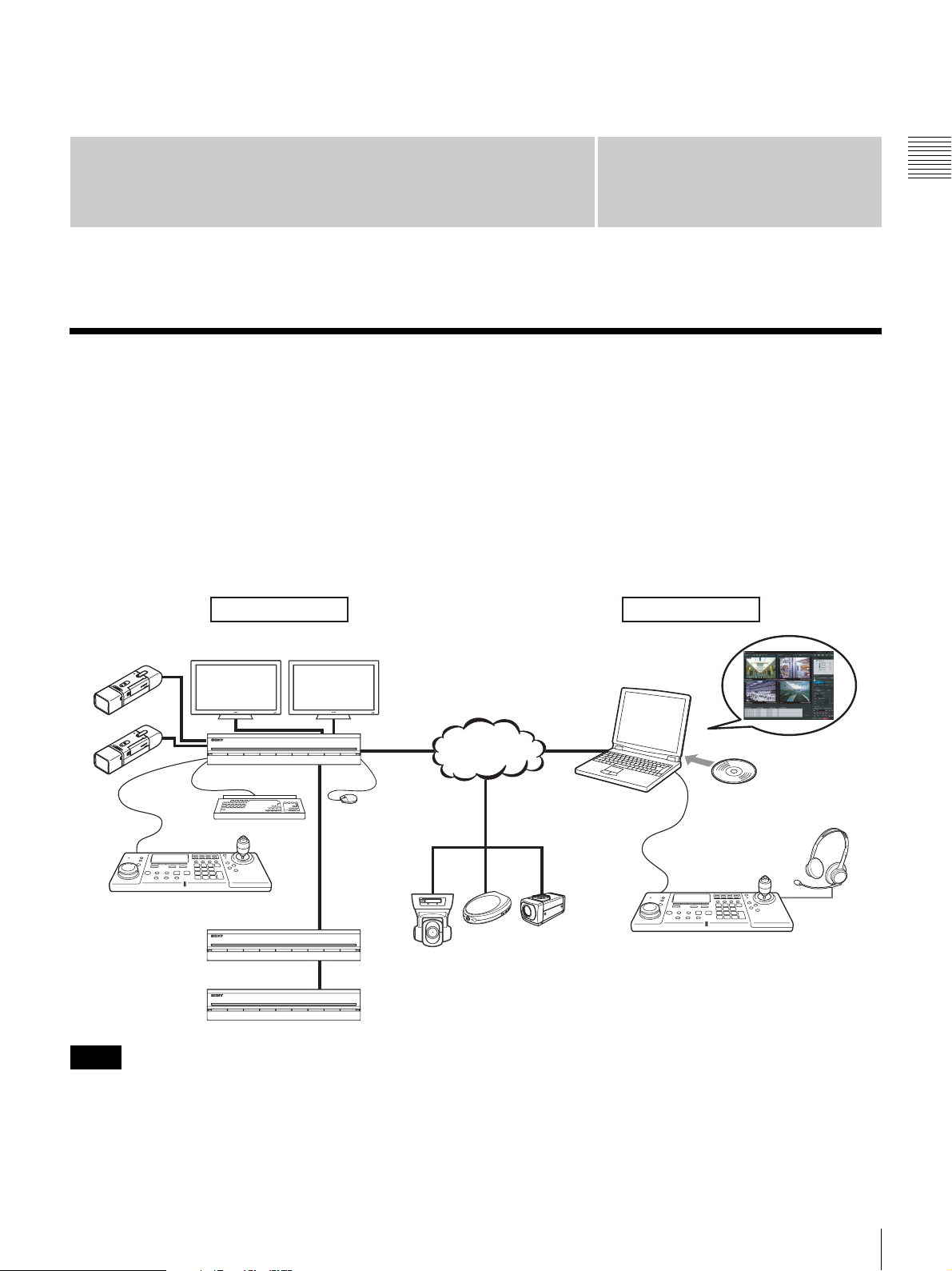
Configuration example in RM-NS1000 mode:
When using the NSR-1000 series or RealShot Manager Advanced, perform operation in RM-NS1000 mode.
Machine room Surveillance room
Chapter 1 Introduction
Analog cameras
NSR-1000 Series
system controller
RM-NS1000
NSRE-S200
NSRE-S200
Note
A keyboard and mouse are required when logging on to the NSR-1000 series or RealShot Manager Advanced.
Monitors
Network
Mouse
Keyboard
Surveillance camera
Monitoring and configuration via
system controller with RealShot
Manager Advanced Client.
Install
Windows
Computer
RealShot Manager Advanced
Monitoring software
system controller
RM-NS1000
Headphones
Function Overview
5
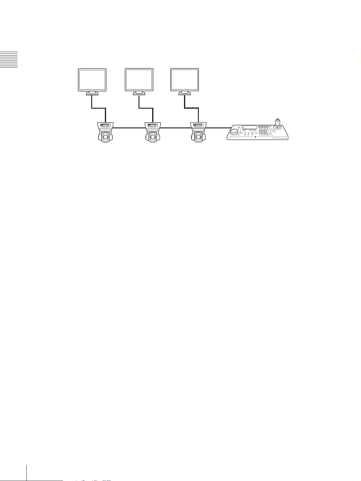
Configuration example in Pelco mode:
When connecting a Pelco-D or -P protocol camera directly to the system controller via the RS-485 port to perform pan,
tilt, and zoom control, perform operation in Pelco mode.
Chapter 1 Introduction
Monitors
Video Out Video Out Video Out
Pelco-D or -P protocol camera
system controller
RM-NS1000
6
Function Overview

Highly functional system controller with support
for two modes
The system controller is provided with RM-NS1000 mode,
and Pelco to select from in accordance with your
surveillance server, software, and cameras. You can
operate various functions remotely such as monitoring,
searching, and playback.
Changing the screen (layout)
You can change the screen layout when your are
monitoring live images or playing back recorded images.
Selecting a camera
You can use the numeric keypad or joystick to select the
camera to control.
Camera control
You can perform operations such as panning, tilting, and
zooming, adjusting the focus and iris, and presetting
camera positions.
Panning, tilting, and zooming are performed by moving
the joystick up, down, left, and right.
Recording images, and playing back and
searching for recorded images
You can remotely perform operations such as recording
images and playing back, pausing, and frame-by-frame
forwarding recorded images. It is also possible, for
example, to switch the screen display (live/playback)
mode and search for and export recorded images.
Precautions and Limitations
Chapter 1 Introduction
• The joystick is a precision part, so do not use excessive
force when operating it. Doing so may result in a
malfunction.
• The system controller is designed to be used indoors.
Refrain from using it outdoors.
• Use in locations with excessive smoke, steam, moisture,
or dust may result in a malfunction.
Supported Systems
The system controller supports the following systems.
• Sony NSR-1000-Series Network Surveillance Server
(Version 1.1 or later)
• A computer on which RealShot Manager Advanced
(Version 1.1 or later), an application software with
controls compatible with this equipment, is installed
System controller operation lock
When, for instance, you leave your seat during operation,
you can lock system controller operation to prevent other
people performing operations.
Precautions and Limitations / Supported Systems
7
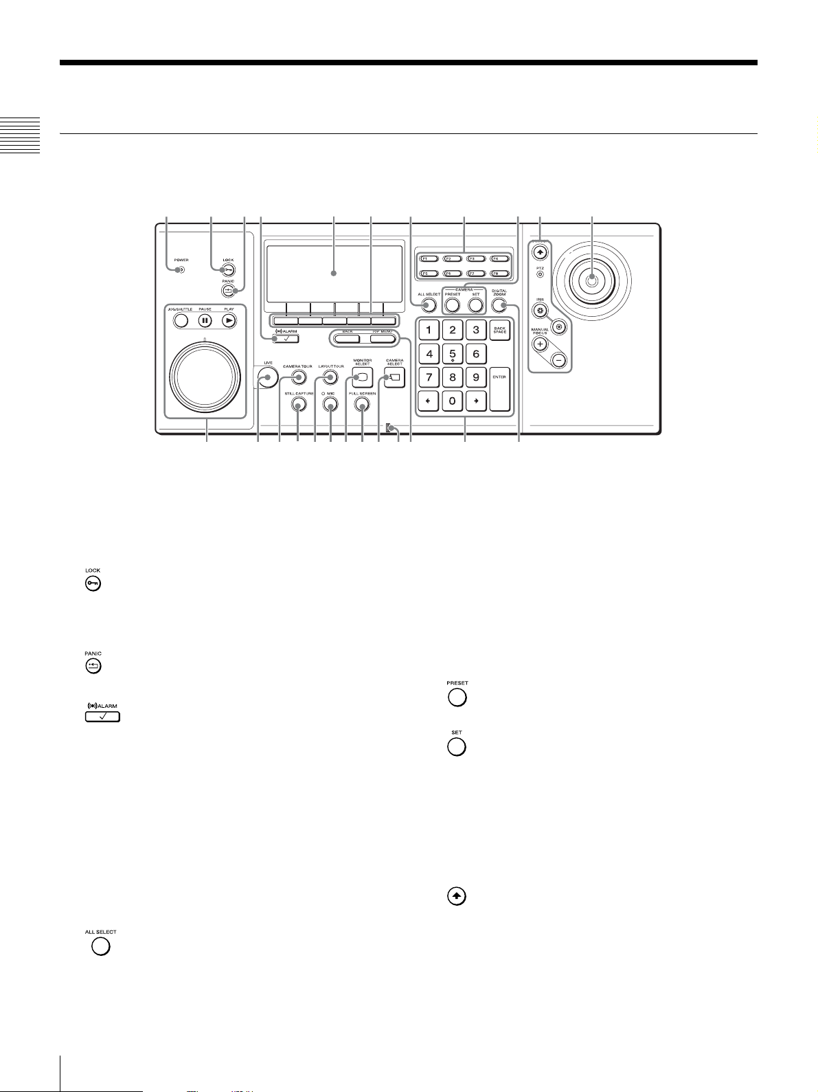
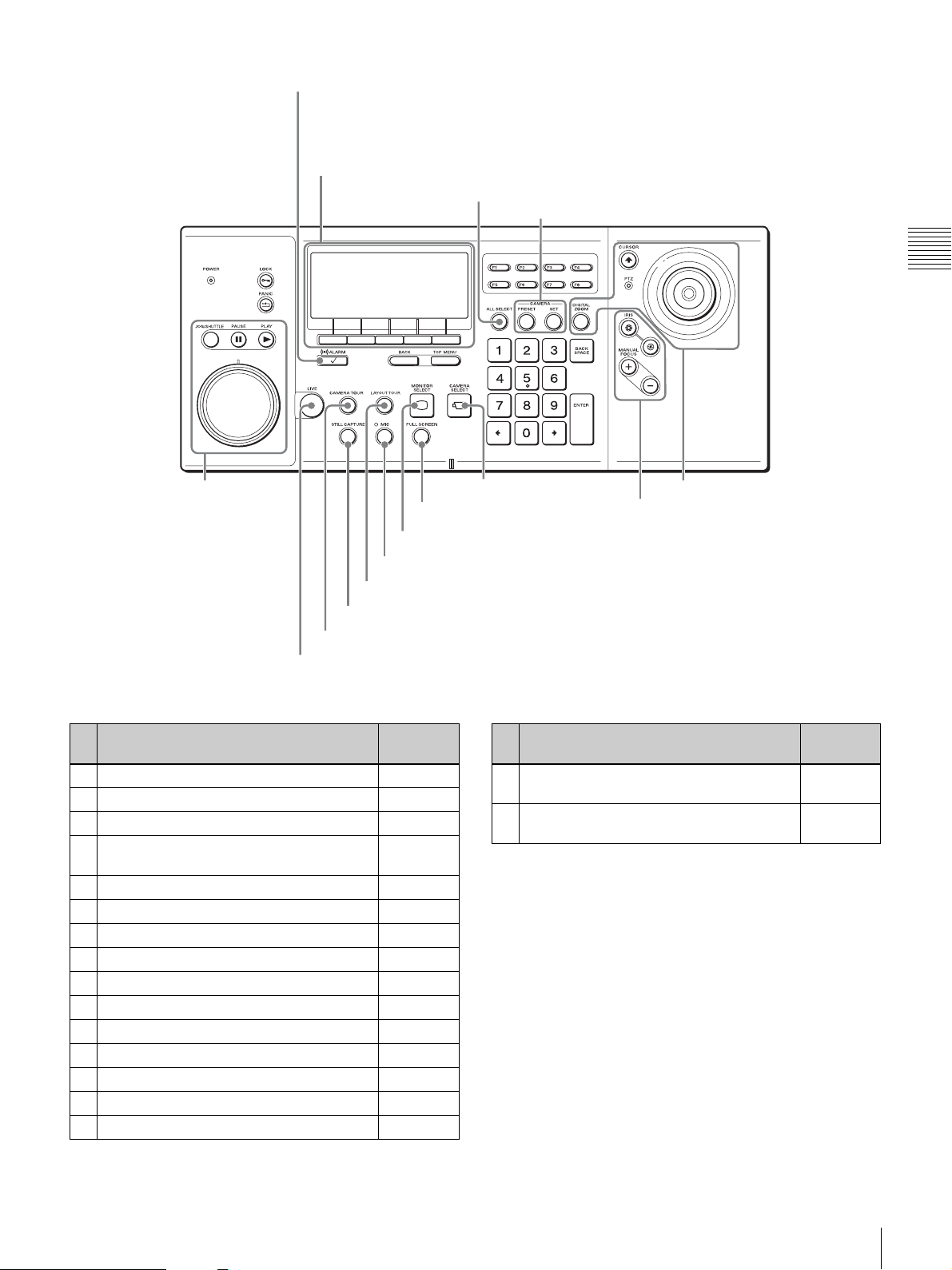
Names of Parts
qdqfqgqhqjqkqlw;waw
w
q
w
Control Panel
Chapter 1 Introduction
23165478
s
A POWER LED
Lights green when the AC adapter is connected to an
outlet.
B (LOCK) button
Locks or unlocks system controller operation.
For the operating procedure, see “Locking Operation”
(page 41).
C (PANIC) button
Returns all cameras to preset position 1.
D (ALARM) button
Used when you use the joystick to select the alarm
history.
E LCD
Used to check the current status and operate each of
the items in the multi function menu.
F Multi function buttons
Used to select/execute each of the items in the multi
function menu.
For the operating procedure, see “Viewing and Using
the LCD” (page 14).
G (ALL SELECT) button
Selects all monitor frames.
09qa
s
H Custom function buttons
I Camera preset area
J Camera control area
d
Used to access pre-registered functions.
F1: Sets image brightness adjustment to auto mode.
F2: Turns the auto focus on.
F3: Turns the DIRECT operations on or off.
F4 to F8: These buttons are not used.
Used to move cameras to preset positions, and
configure preset positions.
(PRESET) button
Moves the selected camera to the preset position.
(SET) button
The current camera position is set as the preset
position.
Used to control cameras.
For the operating procedure, see “Controlling
Cameras” (page 21).
(CURSOR) button/LED
Sets the joystick to mouse mode.
If mouse mode is set, the joystick can be operated in
the same way as a mouse.
In mouse mode, the LED is lit green.
f
8
Names of Parts
PTZ LED
This LED is lit green when pan, tilt, and zoom
operations can be performed.
IRIS buttons
Adjusts the aperture of the currently selected camera
to change the brightness.
Adjust the aperture in the direction to make the
images brighter, and adjust it in the direction to
make the images darker.
MANUAL FOCUS buttons
Adjust the focus of the camera currently selected.
Press when you want to focus on an object in the
distance and press when you want to focus on an
object nearby.
K Joystick
Used to select monitor frames and cameras, and
perform camera pan, tilt, and zoom operations.
You can use the top button as follows.
When PTZ LED is lit: Return selected cameras to
preset position 1.
When PTZ LED is not lit: Confirm selections and
operations.
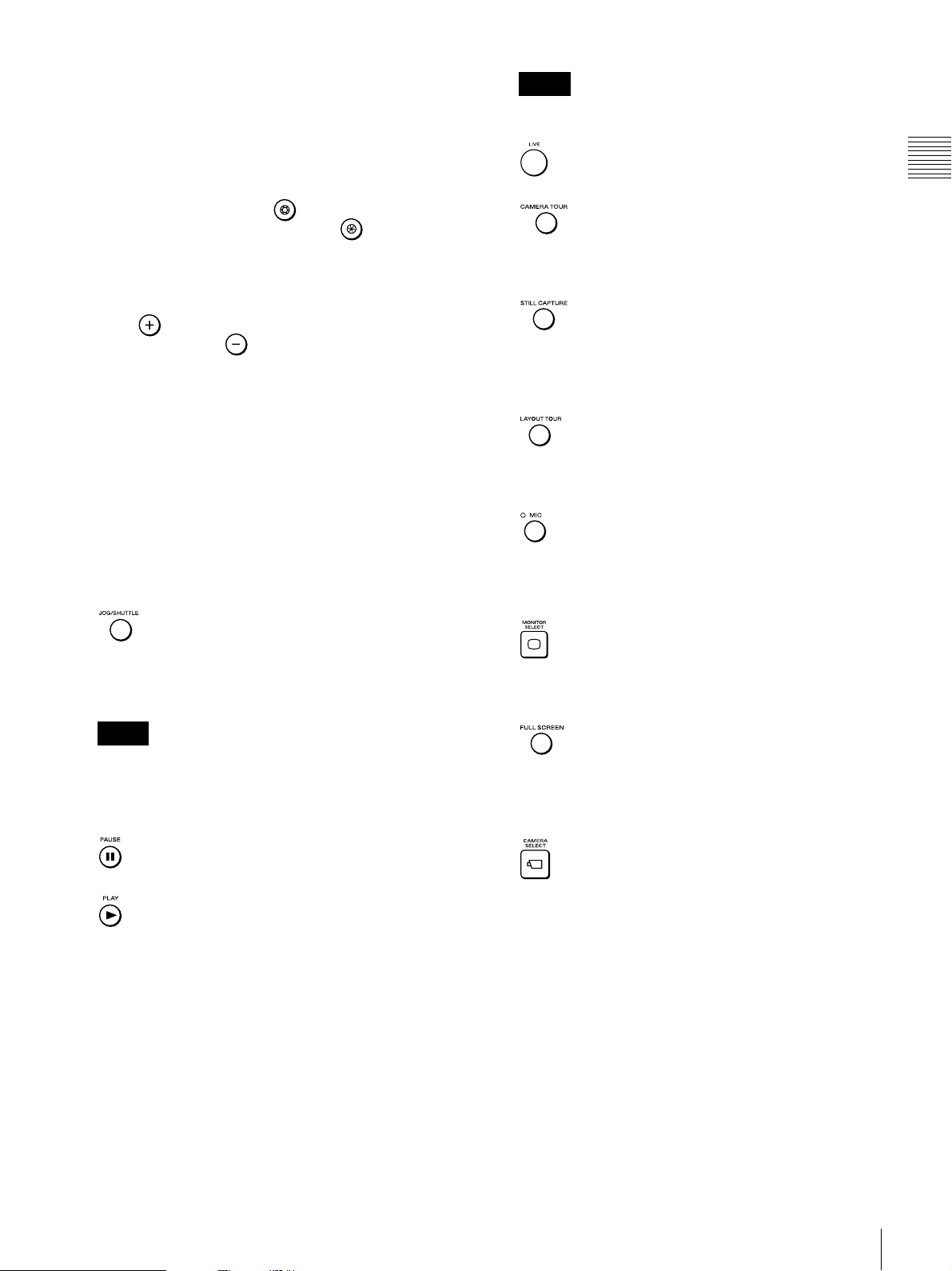
L Search and playback area
Used to search for and play back recorded images.
(JOG/SHUTTLE) button/LED
Enables or disables the jog/shuttle dial.
When lit: Enabled
When not lit: Disabled
Note
If the button is pressed to turn on the LED when the
currently selected monitor frame is PLAYBACK, the
recorded images are paused or played back at +/- speed
according to the position of the shuttle ring.
Note
The jog dial and shuttle ring can only be used when the
JOG/SHUTTLE LED is lit.
M (LIVE) button
Switches the selected monitor frame to live images.
N (CAMERA TOUR) button
Starts or stops the camera tour.
For the operating procedure, see “Performing a
Camera Tour” (page 25).
O (STILL CAPTURE) button
Captures one scene of recorded or live images and
exports it as a still image file.
For the operating procedure, see “Exporting Recorded
Images as Still Images” (page 41).
P (LAYOUT TOUR) button
Starts or stops a registered layout tour.
For the operating procedure, see “Performing a
Camera Tour” (page 25).
Q (MIC) button
While this button is pressed, the LED is lit green and
audio is sent to the camera.
(This function is only available with RealShot
Manager Advanced.)
R (MONITOR SELECT) button
Used to select the monitor frame.
For the operating procedure, see “Selecting a Monitor
Frame” (page 18).
S (FULL SCREEN) button
Displays the current layout (monitor frame
arrangement) over the whole screen.
Switching to full screen hides the pane, control
buttons, and other items.
Chapter 1 Introduction
(PAUSE) button
Pauses playback.
(PLAY) button
Plays the recorded images of the selected monitor
frame.
Jog/shuttle dial
Used to change the playback speed and to frame-byframe forward/rewind during the playback of recorded
images.
The top part is the jog dial and the bottom part is the
shuttle ring.
For how to use the jog dial and shuttle ring, see “Using
the Jog/Shuttle Dial” (page 30).
T (CAMERA SELECT) button
Used to assign a camera to a monitor frame.
For the operating procedure, see “Selecting a
Camera” (page 19).
U Microphone
This is the built-in microphone.
Names of Parts
9
V BACK button/TOP MENU button
231
Displays the multi function menu that is shown on the
LCD.
(This function is only available with RealShot
Manager Advanced.)
Chapter 1 Introduction
For the operating procedure, see “Viewing and Using
the LCD” (page 14).
(BACK) button
Redisplays the previous multi function menu screen.
(TOP MENU) button
Redisplays the top menu.
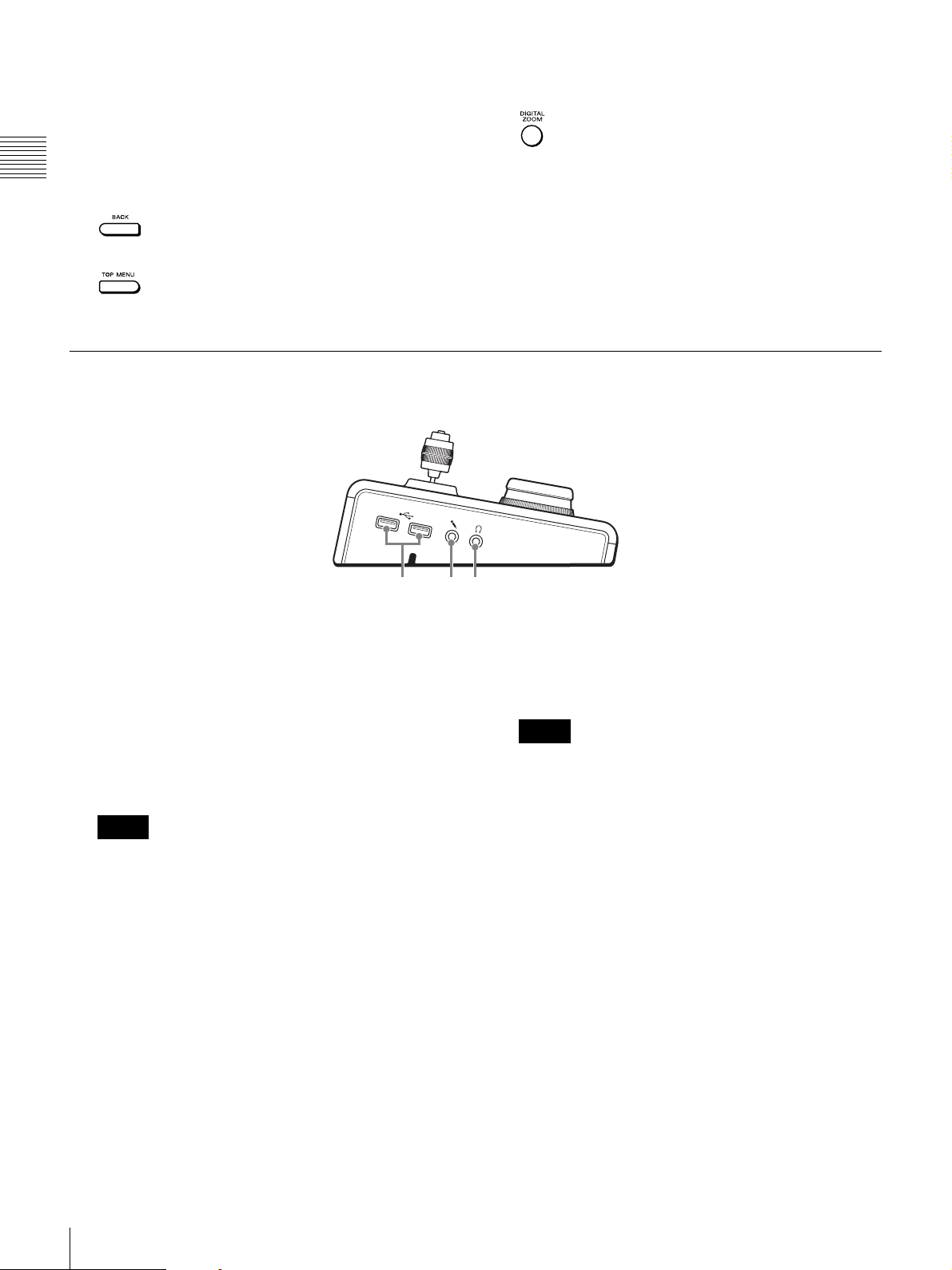
Left Side
W Numeric keypad
Used to enter numbers.
X (DIGITAL ZOOM) button
Turns the digital zoom on or off.
A USB ports
Connect a USB keyboard, USB mouse, or USB flash
memory.
B Microphone input jack
Input audio from a microphone.
This jack supports plug-in-power microphones.
Note
This jack functions only with RealShot Manager
Advanced.
C Headphone jack
Connect headphones.
Note
This jack functions only with RealShot Manager
Advanced.
10
Names of Parts
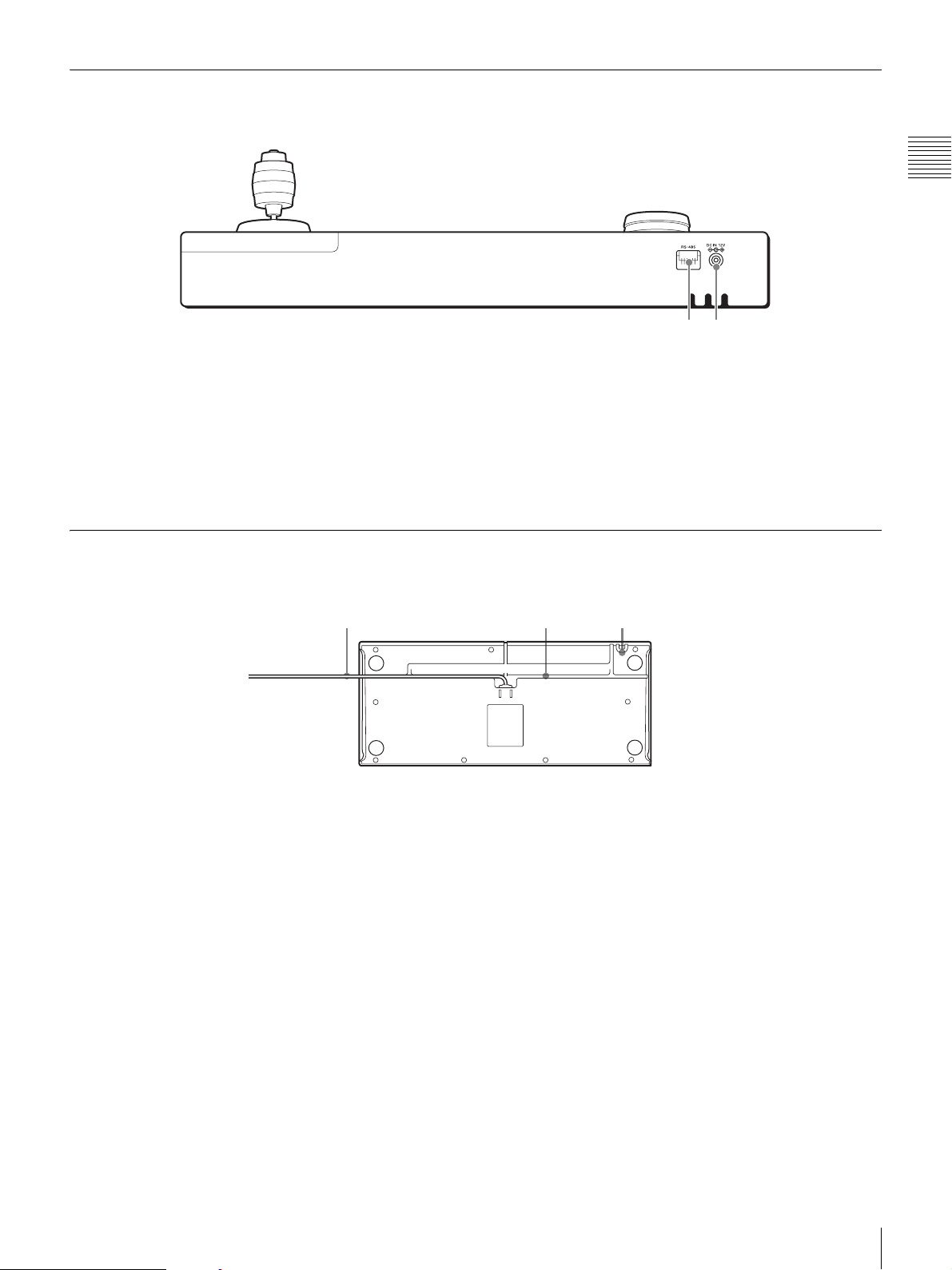
Rear
21
Chapter 1 Introduction
A RS-485 port
Used to control Pelco-D or -P protocol cameras.
For the connection procedure, see “I/O Port”
(page 70).
Bottom
1 23
A USB cable
Connect this cable to a USB port of the NSR-1000
series or a computer with RealShot Manager
Advanced installed.
B Power supply connector
Connect the supplied AC adapter.
C AC cord holder
Wrap the AC adapter cord around the holder to secure
the cord.
B USB cable holder
Thread the USB cable through the groove in
accordance with the location that the system controller
is placed.
Names of Parts
11
Operations in RM-NS1000
Mode
Chapter 2 Operations in RM-NS1000 Mode
Overview
RM-NS1000 mode is for when you are operating the
NSR-1000 series or RealShot Manager Advanced.
This chapter describes the following operations in
RM-NS1000 mode.
• Logging On to the System (page 12)
• Viewing and Using the LCD (page 14)
• Switching Modes (page 15)
• Operations in the Main Screen (page 16)
• Selecting a Monitor Frame (page 18)
• Selecting a Camera (page 19)
• Assigning Cameras to Monitoring Frames (page 19)
• Switching between Monitoring Live Images and Playing
Recorded Images (page 20)
• Controlling Cameras (page 21)
• Using Camera Presets (page 24)
• Performing a Camera Tour (page 25)
• Performing a Layout Tour (page 27)
• Outputting Audio to the Camera (page 28)
• Recording, Searching for, and Playing Back Images
(page 29)
• Exporting Recorded Images (page 38)
• Locking Operation (page 41)
• Setting the System Controller to the Off State (page 42)
• Adjusting the Brightness of the LCD (page 43)
• Multi Function Menu (page 44)
Chapter
2
Logging On to the System
Turn on the power of the system controller, and log on to
the NSR-1000 series or RealShot Manager Advanced.
Note
A keyboard and mouse are required when logging on to the
NSR-1000 series or RealShot Manager Advanced. If the
user name and password consist only of numbers, you can
use the numeric keypad of the system controller to log on.
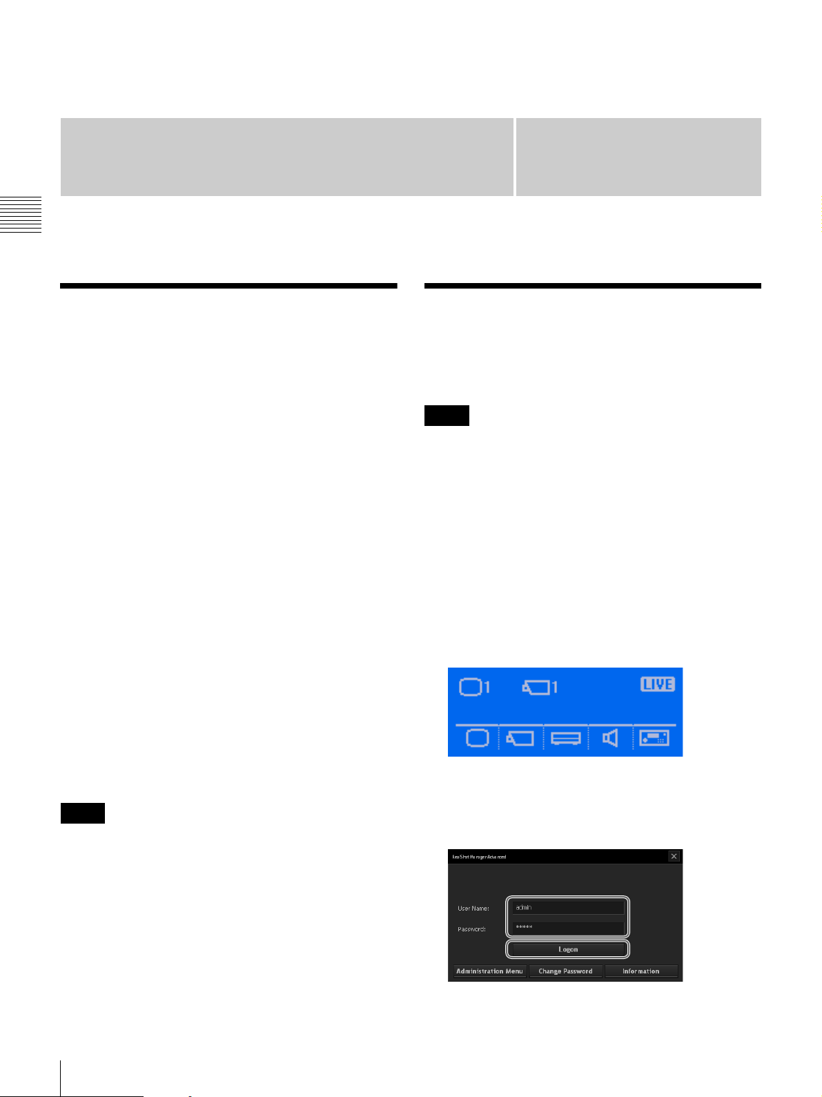
When a password is not set for the system
controller
1
Connect the AC adapter of the system controller to an
outlet.
The power of the system controller turns on and the top
screen appears.
2
Log on to the system.
Note
In this chapter, mainly the screens of RealShot Manager
Advanced are used for the explanations. These screens are
subject to change without notice.
Overview / Logging On to the System
12
Use the keyboard to enter your user name and
password, and click [Logon].
If authentication is successful, the Main screen
appears.
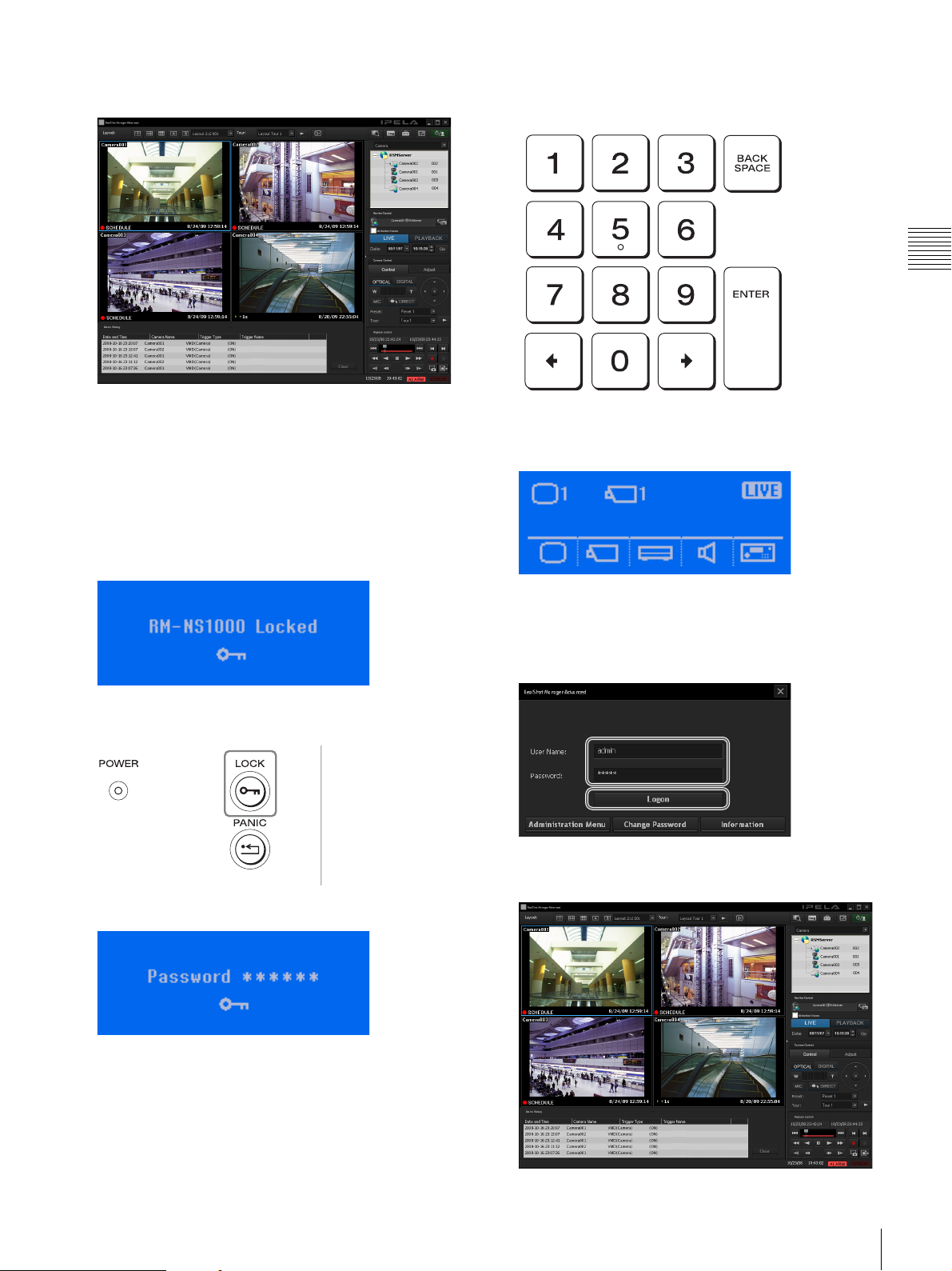
3
Enter the system controller password with the numeric
keypad, and press the ENTER key.
Chapter 2 Operations in RM-NS1000 Mode
When a password is set for the system
controller
1
Connect the AC adapter of the system controller to an
outlet.
When the power turns on, the following screen appears
and the system controller enters a locked state.
2
Press the LOCK button.
If the password is authenticated, the top screen
appears.
4
Log on to the system.
Use the keyboard to enter your user name and
password, and click [Logon].
If authentication is successful, the Main screen
appears.
A screen requesting you to enter the password appears.
Logging On to the System
13
Viewing and Using the LCD
On the LCD, you can check the current status and operate
the multi function menu.
Chapter 2 Operations in RM-NS1000 Mode
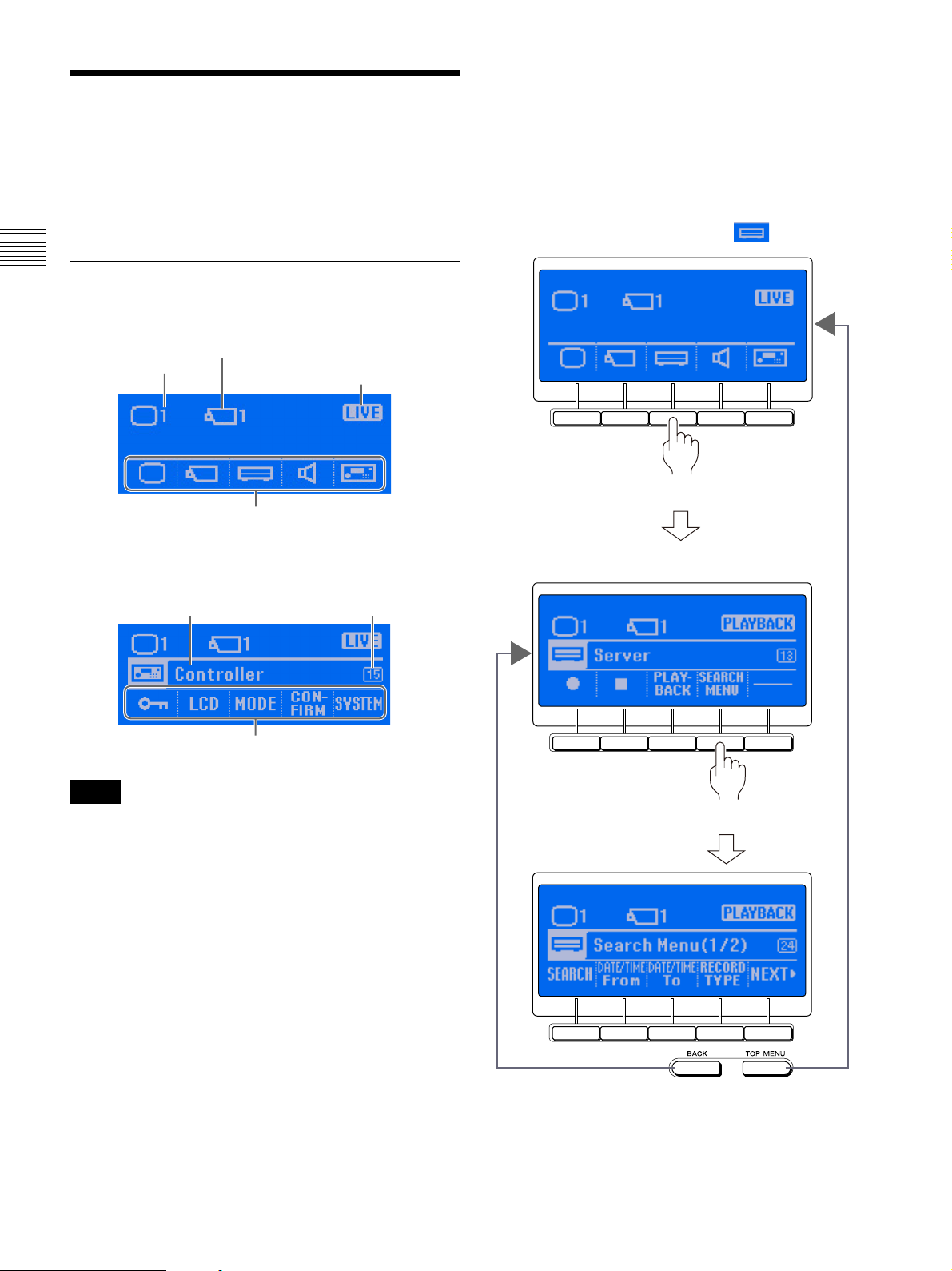
Viewing the LCD
Top screen
Operating the Multi Function Menu
Each item of the multi function menu corresponds to one
of the multi function buttons below the LCD.
When you want to select or operate an item of the multi
function menu, press the button directly below the item to
display a screen that corresponds with that item.
Example: When operating the menu
Currently selected
monitor frame number
Currently selected camera ID
Current monitor frame status
Multi function menu
When you have entered the multi function menu
Example: Controller screen
Menu name
Submenu
Note
Code number
Code numbers are numbers to help you refer to this guide.
For details on how to use code numbers, see “Screen
Index” (page 63).
Press the button
The Server screen appears
Press the button
14
Viewing and Using the LCD
Return to the
previous screen
Return to the
top screen
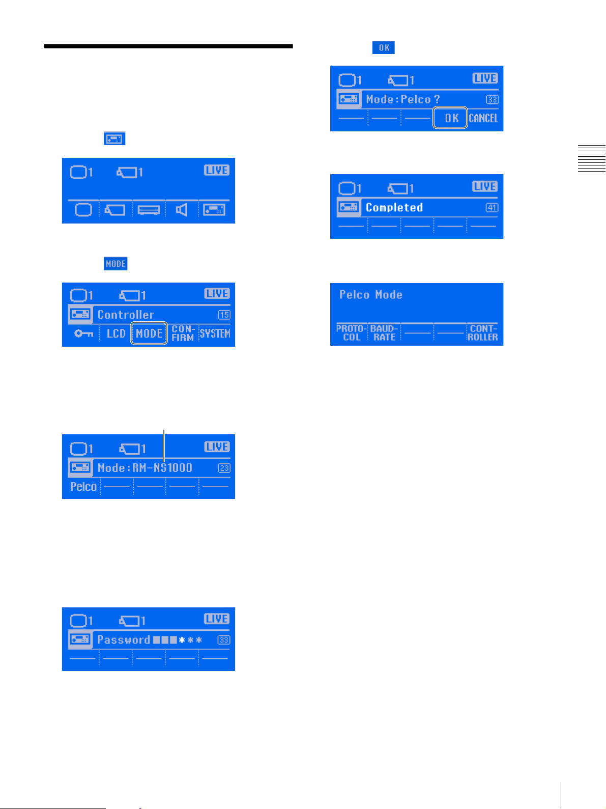
Switching Modes
Switch to RM-NS1000 mode or Pelco mode in accordance
with the devices you are using.
1
Press the button.
The Controller menu screen appears.
2
Press the (MODE) button.
5
Press the (OK) button.
The setting complete screen appears, and the
“Completed” indication appears.
The mode is switched, and the top screen of the
selected mode appears.
Chapter 2 Operations in RM-NS1000 Mode
The Mode screen appears.
3
Press the button for the mode to which you want to
switch.
Current mode
If a password is set, a screen requesting you to enter
the password appears. Go to step 4.
If a password is not set, a confirmation screen appears.
Go to step 5.
4
Enter the password with the numeric keypad, and press
the ENTER key.
If the password is authenticated, a confirmation screen
appears.
Switching Modes
15
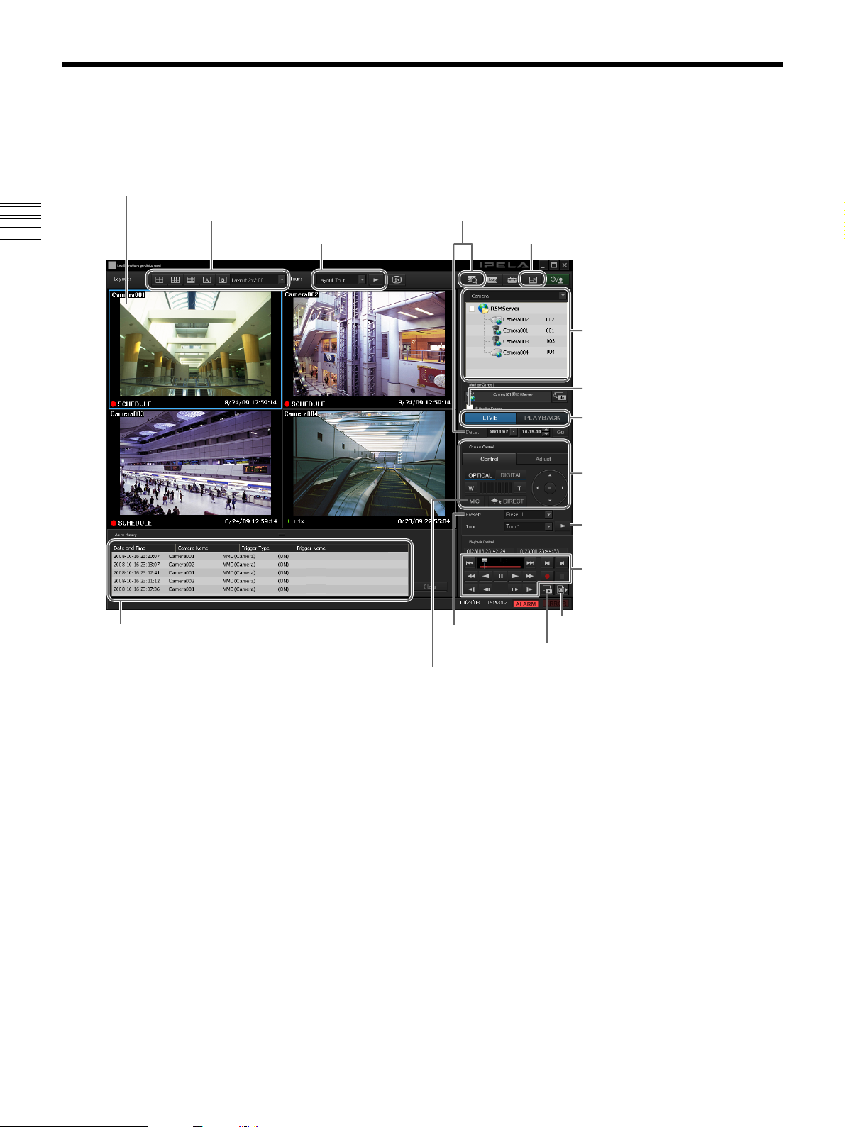
Operations in the Main Screen
The Main screen of the NSR-1000 series and RealShot Manager Advanced and the system controller are linked as shown
below.
1Selecting a monitor frame
2Selecting a layout
Chapter 2 Operations in RM-NS1000 Mode
qjPlaying back recorded images from the
alarm history
3Layout tour
4Searching and playing back
5Full screen display
6Selecting a camera
7All monitor frames
8Switching live / playback
9Camera control
0Adjusting the camera
qaCamera tour
qsPlayback operations
qgMoving to a
preset position
qhMicrophone input (RealShot Manager Advanced only)
qdExporting recorded images
qfCapturing still images
16
Operations in the Main Screen
qjPlaying back recorded images from the alarm history
2Selecting a layout
4Specifying a date and time and then playing back recorded images
qsPlayback operations
qdExporting recorded images
7All monitor frames
qgMoving to a preset position
Chapter 2 Operations in RM-NS1000 Mode
qsPlayback
operations
3Performing a layout tour
qfCapturing still images
qaPerforming a camera tour
8Switching live / playback
5Full screen display
1Selecting a monitor frame
qhMicrophone input (RealShot Manager Advanced only)
For details on the operations, see the following pages.
Operation Reference
Page
1 Selecting a monitor frame 18, 19
2 Selecting a layout 45
3 Performing a layout tour 27
4 Specifying a date and time and then
playing back recorded images
5 Full screen display 18
6 Selecting a camera 19
7 All monitor frames 8
8 Switching live / playback 20
9 Camera control 21
0 Adjusting the camera 21
qa Performing a camera tour 25
qs Playback operations 31
qd Exporting recorded images 38
qf Capturing still images 41
qg Moving to a preset position 24
32
6Selecting a camera
9Camera control
0Adjusting the camera
Operation Reference
qh Microphone input (RealShot Manager
Advanced only)
qj Playing back recorded images from the
alarm history
Page
28
33
Operations in the Main Screen
17
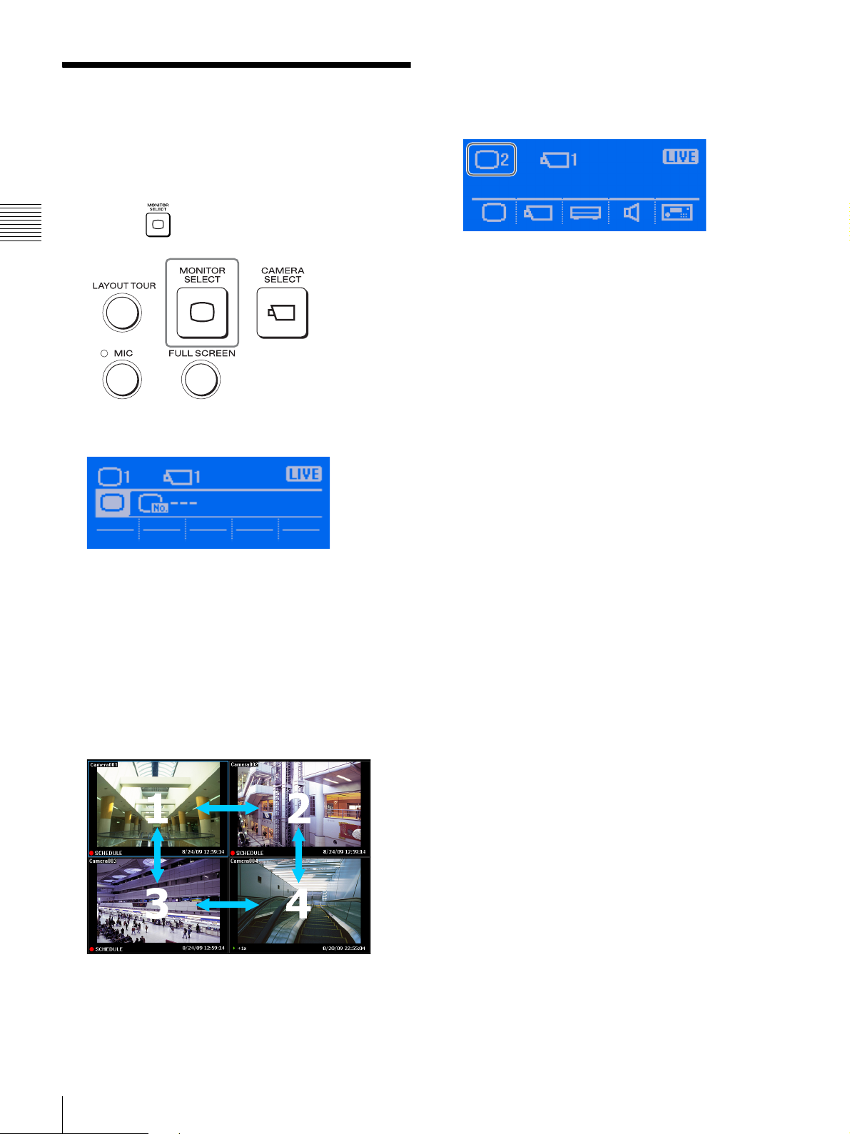
Selecting a Monitor Frame
Use the numeric keypad or joystick to select a monitor
frame.
1
Chapter 2 Operations in RM-NS1000 Mode
Press the (MONITOR SELECT) button.
The following screen appears.
The light blue frame moves to the selected monitor
frame, and the selected monitor frame number appears
in the screen on the LCD.
Example: When monitor frame 2 is selected
At the same time, a monitor frame number appears in
each of the monitor frames in the Main screen.
2
Select a monitor frame.
To select with the numeric keypad:
Enter the monitor frame number, and press the
ENTER key.
To select with the joystick:
Move the joystick left or right to select the monitor
frame, and press the top button.
18
Selecting a Monitor Frame
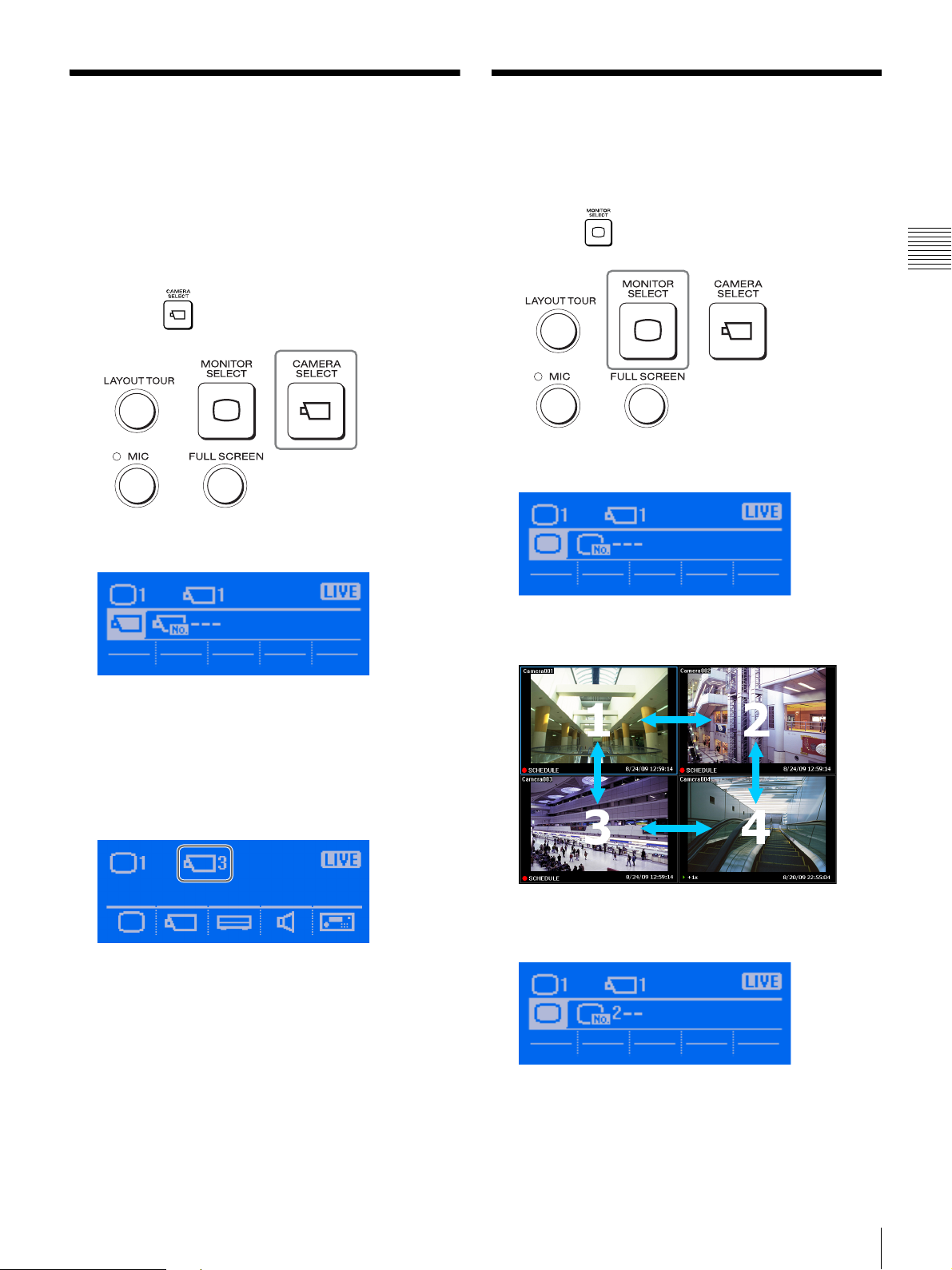
Selecting a Camera
Select the camera for the live images you want to monitor
or recorded images you want to play.
You can use the joystick or numeric keypad to select the
camera.
1
Select the monitor frame in which to display the
camera images.
2
Press the (CAMERA SELECT) button.
The following screen appears.
Assigning Cameras to Monitoring Frames
You can select a monitor frame and assign a camera.
1
Press the (MONITOR SELECT) button.
The following screen appears.
Chapter 2 Operations in RM-NS1000 Mode
3
Enter the camera ID with the numeric keypad, and
press the ENTER key.
The images of the selected camera appear in the
monitor frame, and the selected camera ID appears in
the screen on the LCD.
Example: When “003” is entered and selected
At the same time, a monitor frame number appears in
each of the monitor frames in the Main screen.
2
Enter the monitor frame number with the numeric
keypad.
Assign a camera next.
Selecting a Camera / Assigning Cameras to Monitoring Frames
19

3
Press the (CAMERA SELECT) button.
Switching between Monitoring Live Images and Playing Recorded Images
Chapter 2 Operations in RM-NS1000 Mode
The light blue frame moves to the selected monitor
frame, and the next screen appears.
4
Enter the camera ID with the numeric keypad.
5
Press the ENTER key.
The camera is assigned to the monitor frame.
You can switch the status of the selected monitor frame
(monitoring live images and playing recorded images).
Switching to live images
Press the LIVE button.
Switching to playing recorded images
Press the PLAY button.
20
Switching between Monitoring Live Images and Playing Recorded Images
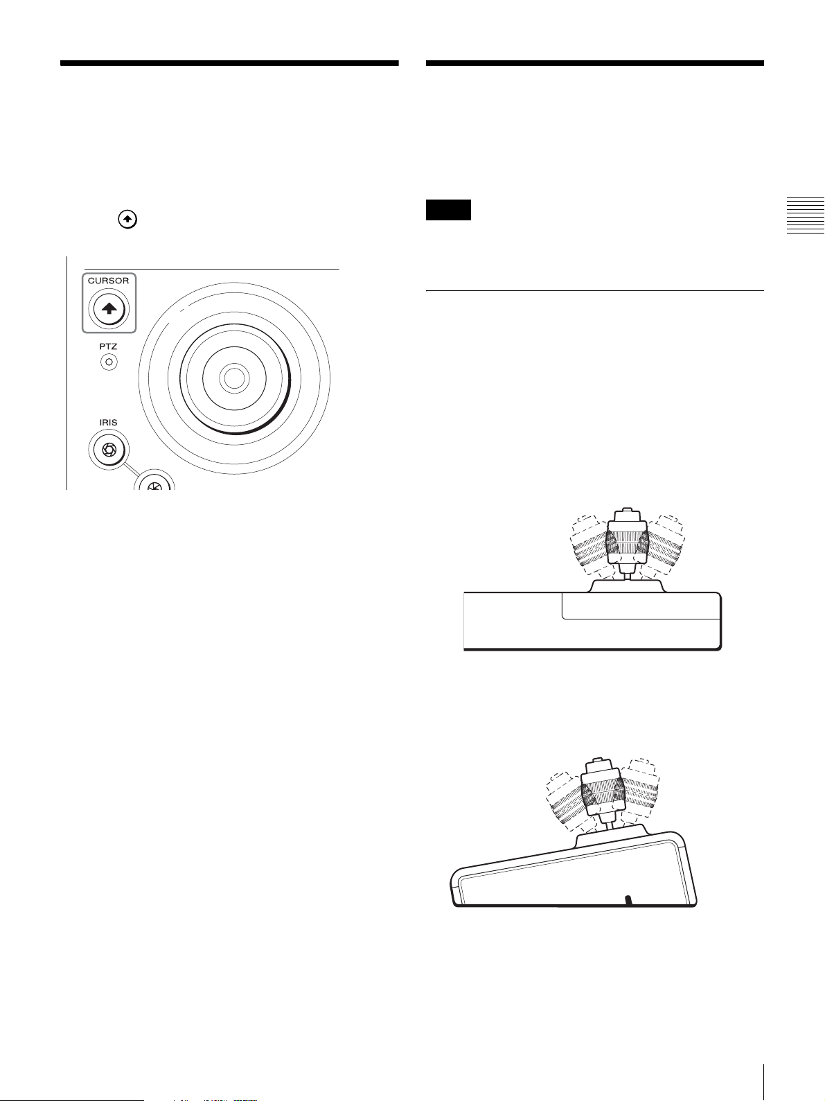
Setting the Joystick to Mouse Mode
If the mouse mode is set, you can perform mouse
operations using the joystick.
Controlling Cameras
For a camera equipped with pan and tilt functions, you can
monitor the images from the camera while performing
operations such as panning, tilting, and zooming.
Press the (CURSOR) button.
The LED is lit green, and the joystick enters mouse mode.
Note
The PTZ LED on the system controller lights green when
pan, tilt, and zoom operations can be performed.
Performing Pan, Tilt, and Zoom Operations
The panning and tilting operations are achieved by moving
the joystick in the direction in which you want the camera
to face.
Panning
Move the joystick right or left.
Front view
Chapter 2 Operations in RM-NS1000 Mode
Tilting
Move the joystick up or down.
Right view
Setting the Joystick to Mouse Mode / Controlling Cameras
21
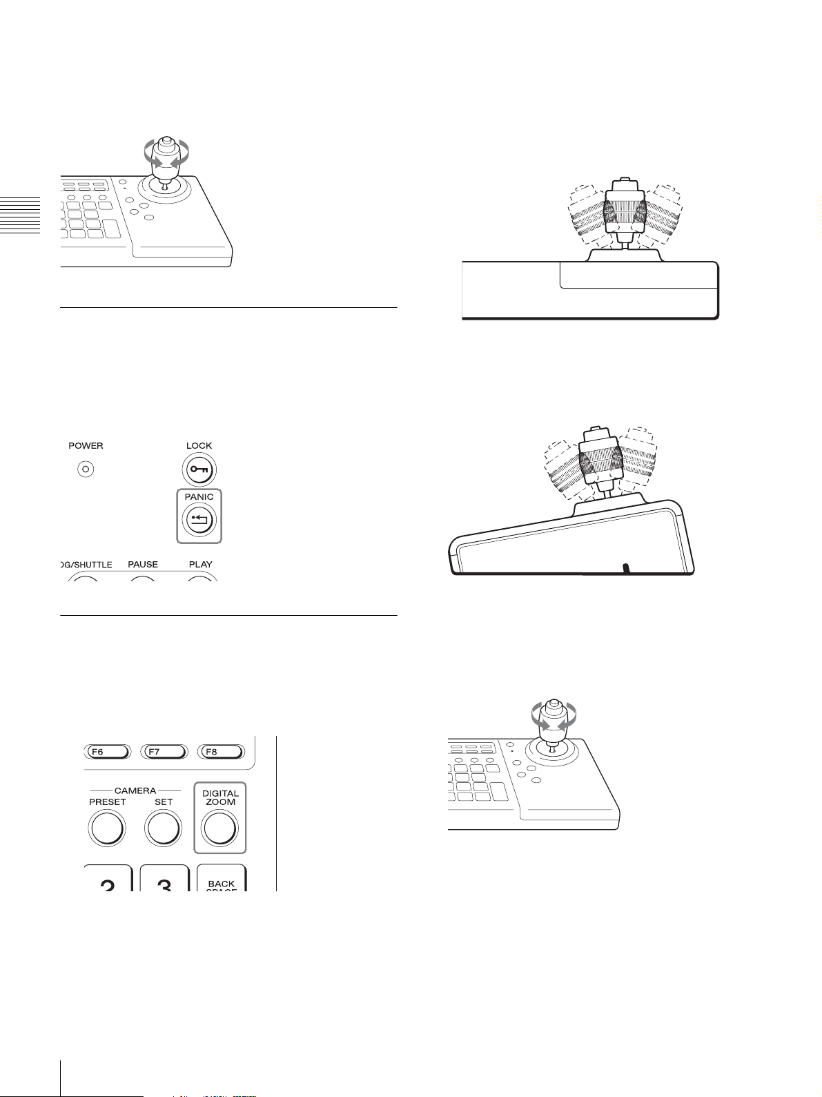
Zooming
Rotate the z-axis of the joystick clockwise to zoom in
(Tele), and rotate it counterclockwise to zoom out (Wide).
Chapter 2 Operations in RM-NS1000 Mode
Returning All Cameras to Preset
2
Use the joystick to operate pan, tilt, and zoom.
Panning
Move the joystick right or left.
Front view
Position 1
Press the PANIC button to return all PTZ cameras that are
displayed in the camera tree on the NSR-1000 series or
RealShot Manager Advanced to preset position 1.
Using the Digital Zoom
You can also perform digital pan and tilt during digital
zoom.
1
Press the DIGITAL ZOOM button.
Tilting
Move the joystick up or down.
Right view
Zooming
Rotate the z-axis of the joystick clockwise to zoom in
(Tele), and rotate it counterclockwise to zoom out
(Wide).
22
Controlling Cameras
Returning to optical zoom
Press the DIGITAL ZOOM button again.
If the [Camera Control] pane is displayed, [DIGITAL]
lights.
 Loading...