

Sony Ipela PCS-XG55,Ipela PCS-XG80,Ipela PCS-XG80S,Ipela PCS-XG55S Integration Manual

HD VISUAL COMMUNICATION SYSTEM
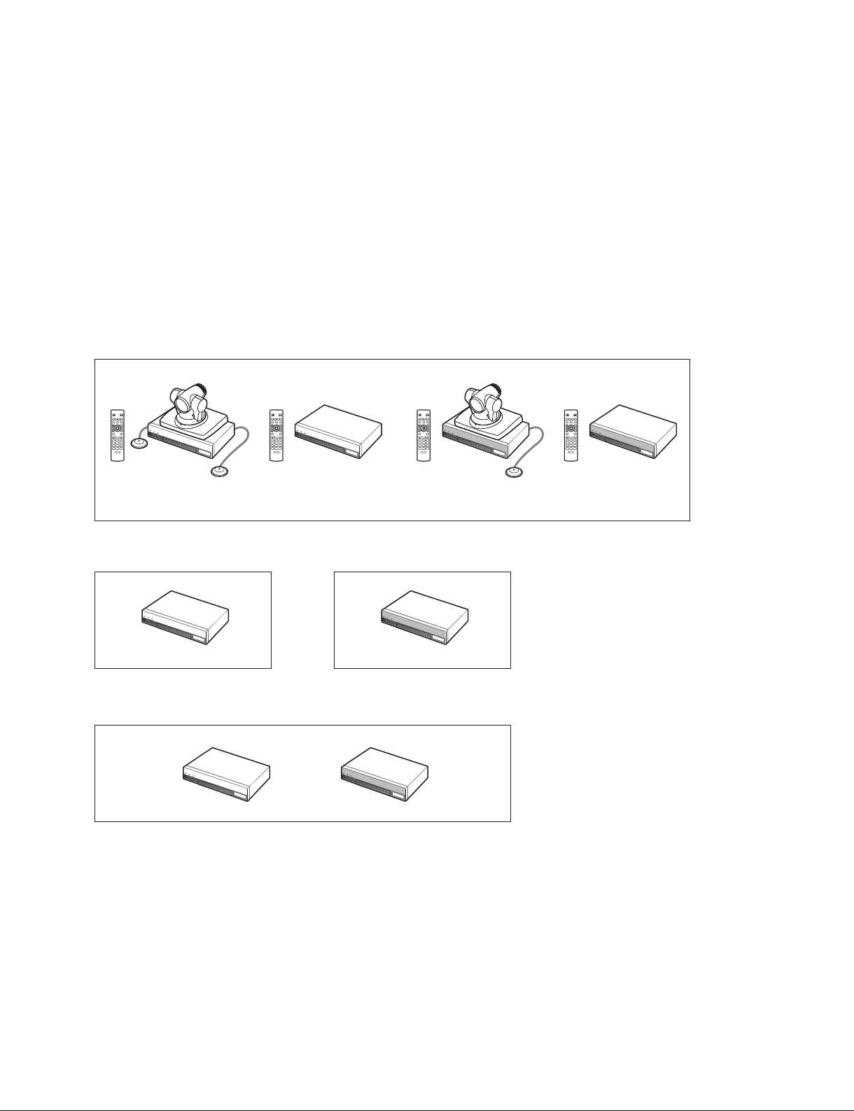
PCS-XG80
PCS-XG80S
PCS-XG55
PCS-XG55S
SYSTEM INTEGRATION MANUAL
1st Edition (Revised 1)
Version 2.0 and Later (PCS-XG80)
Version 2.1 and Later (PCS-XG55)

!警告
このマニュアルは,サービス専用です。
お客様が,このマニュアルに記載された設置や保守,点検,修理などを行うと感電や火災,
人身事故につながることがあります。
危険をさけるため,サービストレーニングを受けた技術者のみご使用ください。
! WARNING
This manual is intended for qualifi ed service personnel only.
To reduce the risk of electric shock, fi re or injury, do not perform any servicing other than that
contained in the operating instructions unless you are qualifi ed to do so. Refer all servicing to
qualifi ed service personnel.
! WARNUNG
Die Anleitung ist nur für qualifi ziertes Fachpersonal bestimmt.
Alle Wartungsarbeiten dürfen nur von qualifi ziertem Fachpersonal ausgeführt werden. Um die
Gefahr eines elektrischen Schlages, Feuergefahr und Verletzungen zu vermeiden, sind bei
Wartungsarbeiten strikt die Angaben in der Anleitung zu befolgen. Andere als die angegeben
Wartungsarbeiten dürfen nur von Personen ausgeführt werden, die eine spezielle Befähigung
dazu besitzen.
! AVERTISSEMENT
Ce manual est destiné uniquement aux personnes compétentes en charge de l’entretien. Afi n
de réduire les risques de décharge électrique, d’incendie ou de blessure n’effectuer que les
réparations indiquées dans le mode d’emploi à moins d’être qualifi é pour en effectuer d’autres.
Pour toute réparation faire appel à une personne compétente uniquement.
PCS-XG80

Table of Contents
1. Installation
1-1. Layout Information for PCS-XG Series Models ............. 1-3
1-1-1. Simple Connection .................................................1-3
1-1-2. Camera Connection................................................ 1-4
1-1-3. Microphone Connection ...................................... 1-10
1-1-4. Audio Specifi cations and Settings .......................1-13
1-1-5. Echo Canceller ..................................................... 1-19
1-1-6. Monitor Connection ............................................. 1-20
1-1-7. Pen Tablet.............................................................1-21
1-1-8. Remote Commander and Pairing .........................1-22
1-1-9. Two Serial Ports on PCS-XG Series Main Unit ... 1-24
1-2. System Connections ...................................................... 1-26
1-2-1. System Connection via a LAN and a SIP ............ 1-26
1-2-2. PCS-XG Series Models Connection Using SIP ... 1-27
1-2-3. System Connection via an ISDN ......................... 1-28
1-2-4. System Confi guration Using Two IP Connections
(PCS-XG80/XG80S only) ...................................1-29
1-2-5. IPv6 ...................................................................... 1-30
1-2-6. Multipoint Connection (Example of Connection)
(Main terminal: PCS-XG80/XG80S only) ..........1-30
1-2-7. Multipoint Connection (Screen Display)
(Main terminal: PCS-XG80/XG80S only) ..........1-33
1-2-8. To Connect a Video Equipment for Input ............ 1-41
1-3. Difference between PCS-XG80/XG80S and PCS-XG55/
XG55S ........................................................................... 1-42
2. Setup/Alignment and Video Mode
3. Maintenance
3-1. Firmware Update ............................................................. 3-1
3-1-1. Firmware Update by Using WEB Control ............. 3-2
3-1-2. Firmware Update by Using Memory Stick ............ 3-6
3-1-3. Firmware Update by Using Service Menu ............3-8
3-1-4. Upgrading Using FTP (No Support) .................... 3-10
3-2. Optional Software Installation ......................................3-10
3-3. Confi rmation Procedure of Local Terminal Operation
Using Self-Loop ............................................................ 3-11
3-4. Description on Status Menu .......................................... 3-13
3-4-1. Network Routing Check ......................................3-13
3-4-2. Communication Mode Status...............................3-14
3-4-3. LAN Line Status .................................................. 3-15
3-4-4. Machine Information ...........................................3-16
3-4-5. Peripheral Status .................................................. 3-18
3-5. Description on Service Menu ........................................ 3-19
3-5-1. Displaying the Service Menu ............................... 3-19
3-5-2. Description on Service Menu ..............................3-20
3-6. How to Take Logs .........................................................3-23
3-6-1. Supported Logs ....................................................3-23
3-6-2. System Log .......................................................... 3-23
3-6-3. Operation Log ......................................................3-25
3-6-4. Call Log ............................................................... 3-26
3-7. Network Trouble Check ................................................ 3-27
3-7-1. Test Procedure ...................................................... 3-27
3-7-2. Description of Each Test ...................................... 3-28
3-8. Replacing the Batteries.................................................. 3-32
2-1. Turning the System On/Off ............................................. 2-1
2-1-1. Turning On the System .......................................... 2-1
2-1-2. Turning Off the System .........................................2-1
2-2. Initial Setup and Other Setup .......................................... 2-2
2-2-1. Setup of Your First Time Power-On ...................... 2-2
2-2-2. Other Setup ............................................................ 2-6
2-3. Video Mode and Bandwidth ............................................2-9
2-3-1. 1080i Mode (PCS-XG80/XG80S only) .................2-9
2-3-2. 720P and Other Mode .......................................... 2-10
2-4. Important Information About Installation and Setting of
Connection Using IP Line of Two Networks (PCS-XG80/
XG80S only) .................................................................2-12
PCS-XG80
1

Section 1
Installation
This section describes the typical system connections. Refer to the Operating Instructions supplied with
the PCS-XG Series models.
The difference between PCS-XG80/XG80S and PCS-XG55/XG55S is described in Section 1-3.
This system integration manual defi nes and uses words as below. (See below Fig.)
“PCS-XG Series models” means the four models, that is, PCS-XG80, PCS-XG80S, PCS-XG55 and PCS-XG55S.
“PCS-XG80 main unit” means the codec box of both PCS-XG80 and PCS-XG80S.
“PCS-XG55 main unit” means the codec box of both PCS-XG55 and PCS-XG55S.
“PCS-XG Series main unit” or “main unit” means both “PCS-XG80 main unit” and “PCS-XG55 main unit”.
PCS-XG Series models
/
T
W
PCS-XG80
/
T
W
PCS-XG80S
/
T
W
PCS-XG55
PCS-XG80 main unit PCS-XG55 main unit
“PCS-XG Series main unit” or “main unit”
/
T
W
PCS-XG55S
n
The PCS-XG Series main unit, PCS-RF1 and PCSA-CXG80 all incorporate an RF (radio frequency)
transmitting and receiving module.
For notes on RF waves, refer to the operating instructions supplied with PCS-XG series model.
Position the camera and microphone appropriately in the video conferencing room.
c
You must turn off the power to the PCS-XG Series main unit before attempting to connect the camera to
the main unit using the supplied camera cable. Otherwise, the camera and/or main unit may be damaged,
or the picture may not be displayed.
PCS-XG80
1-1
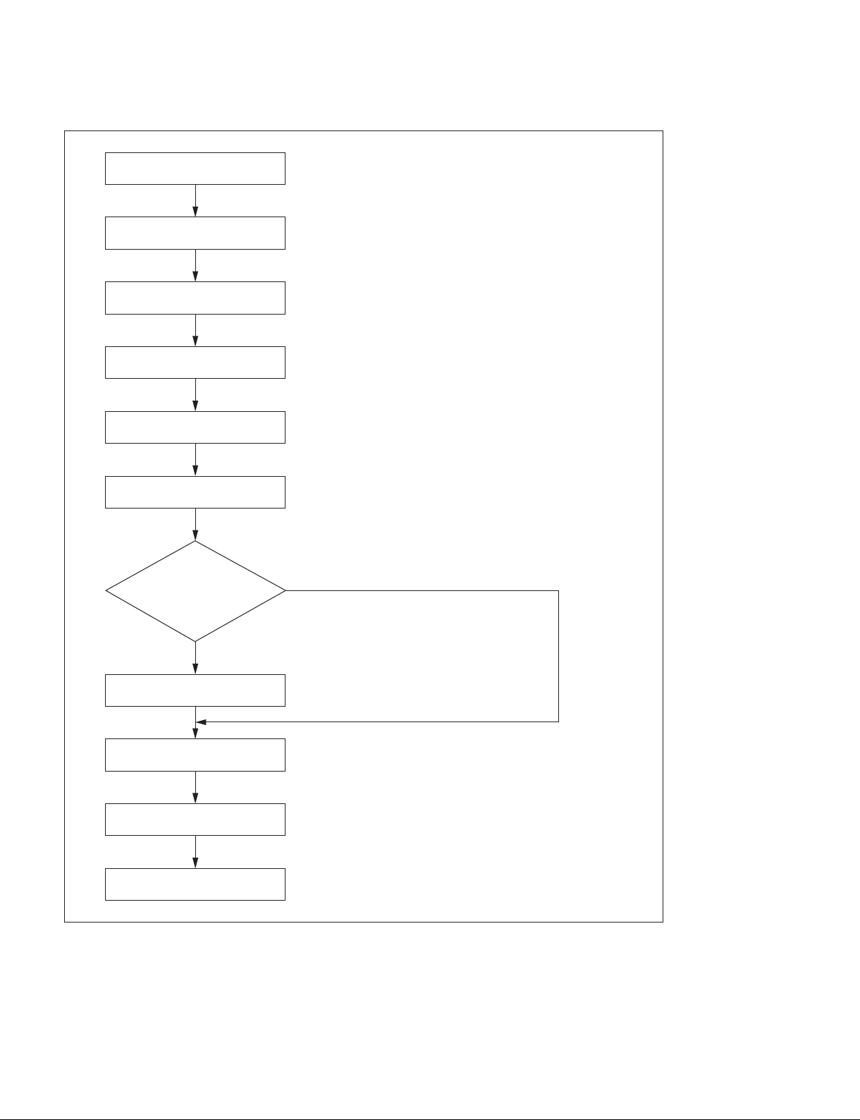
Installation Flowchart
Preparation at
location of installation
Unpacking
Check of supplied accessories
System connections
Turn on the power to the system
and perform initialization
Other setup, if needed
<Refer to “1-1. Layout information for PCS-XG Series models”>
<Refer to “1-1-1. Simple Connection”>
<Refer to “3-8. Replacing the Batteries”>
<Refer to “1-2. System Connections”>
<Refer to “2-1-1. Turning On the System”>
<Refer to “2-2-1. Setup of Your First Time Power-On”>
<Refer to “2-2-2. Other Setup”>
Are/Is the firmware
update and/or the optional
software installation
performed?
Yes
. Firmware update
. Optional software installation
Operation test and confirmation
Turn off the system <Refer to “2-1-2. Turning Off the System”>
End
No
<Refer to “3-1. Firmware Update”>
<Refer to “3-2. Optional Software Installation”>
1-2
PCS-XG80
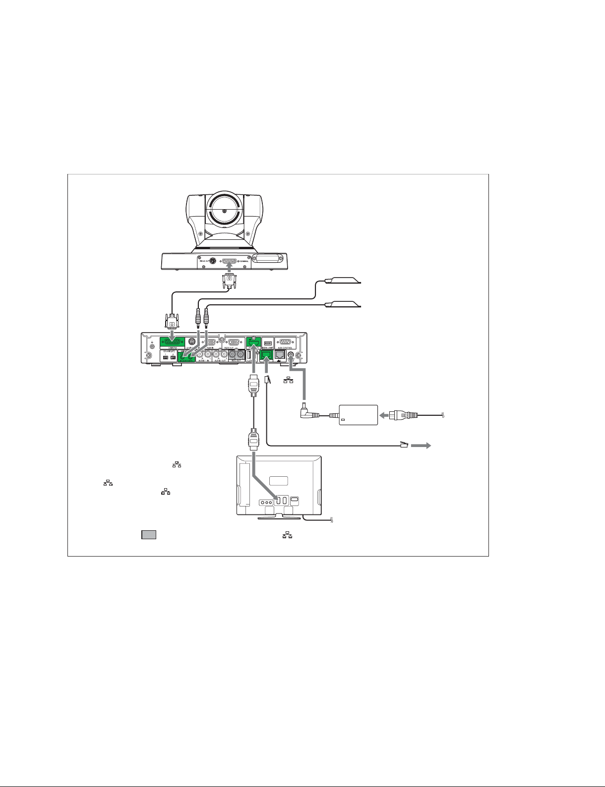
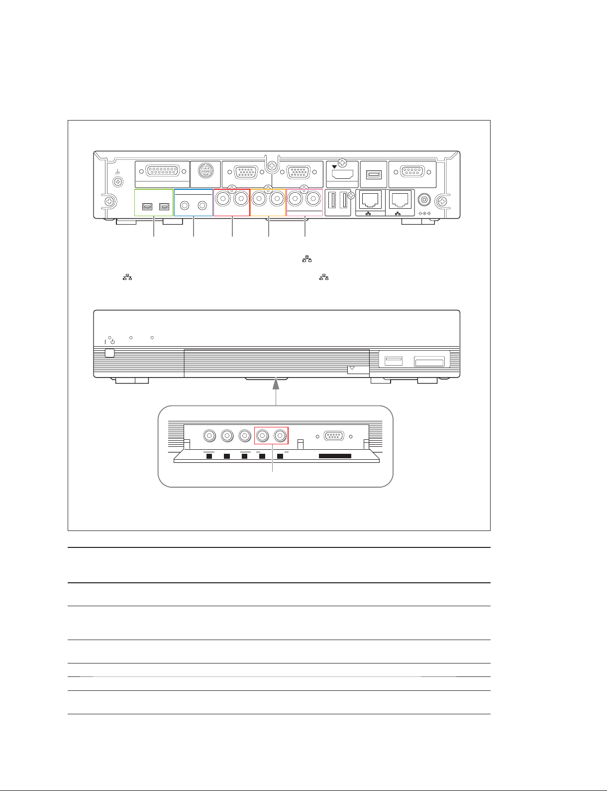
1-1. Layout Information for PCS-XG Series Models
1-1-1. Simple Connection
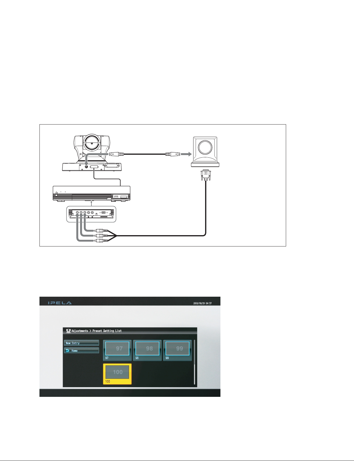
Making a “simple connection”
To start video conferencing by making a “simple connection”, connect the cables to the green connectors,
as shown below.
3 Supplied
2 Supplied cable
3 Supplied
Rear panel
1
Supplied cable
The S VIDEO IN, EC-MIC (A7) 1/2,
AUDIO 1 IN, EXT 1/2, and 2 connectors
are not available on the PCS-XG55 main unit.
* The 1 connector on the PCS-XG80 main
unit corresponds to the connector on the
PCS-XG55 main unit.
Connector caps for REC OUT and 2, indicated by the shading, are fitted at the factory.
to 1
4 Not supplied
1 Connect the HDMI cable. (HD video and stereo audio)
2 Connect the camera cable.
3 Connect the microphones.
4 Connect the network cable.
5 Connect the AC power adaptor.
*
5 Supplied
Not supplied
to LAN
PCS-XG80
1-3
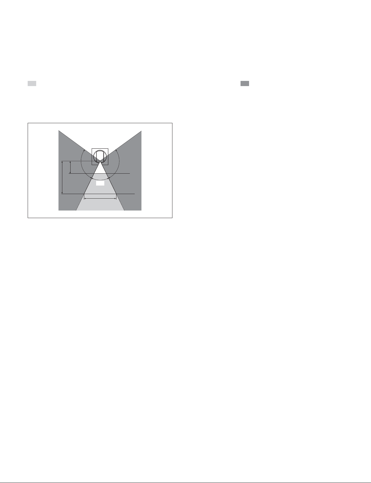
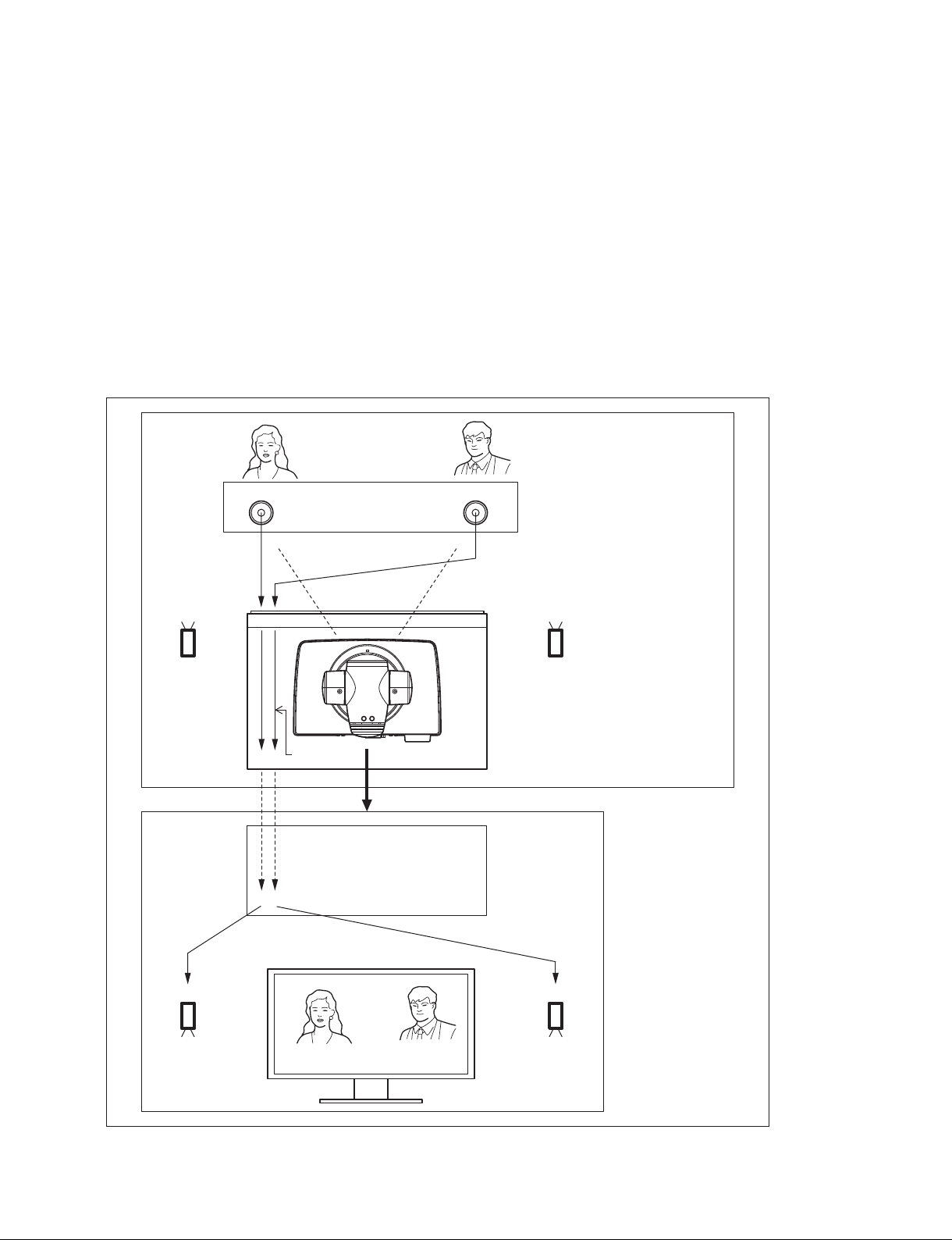
1-1-2. Camera Connection
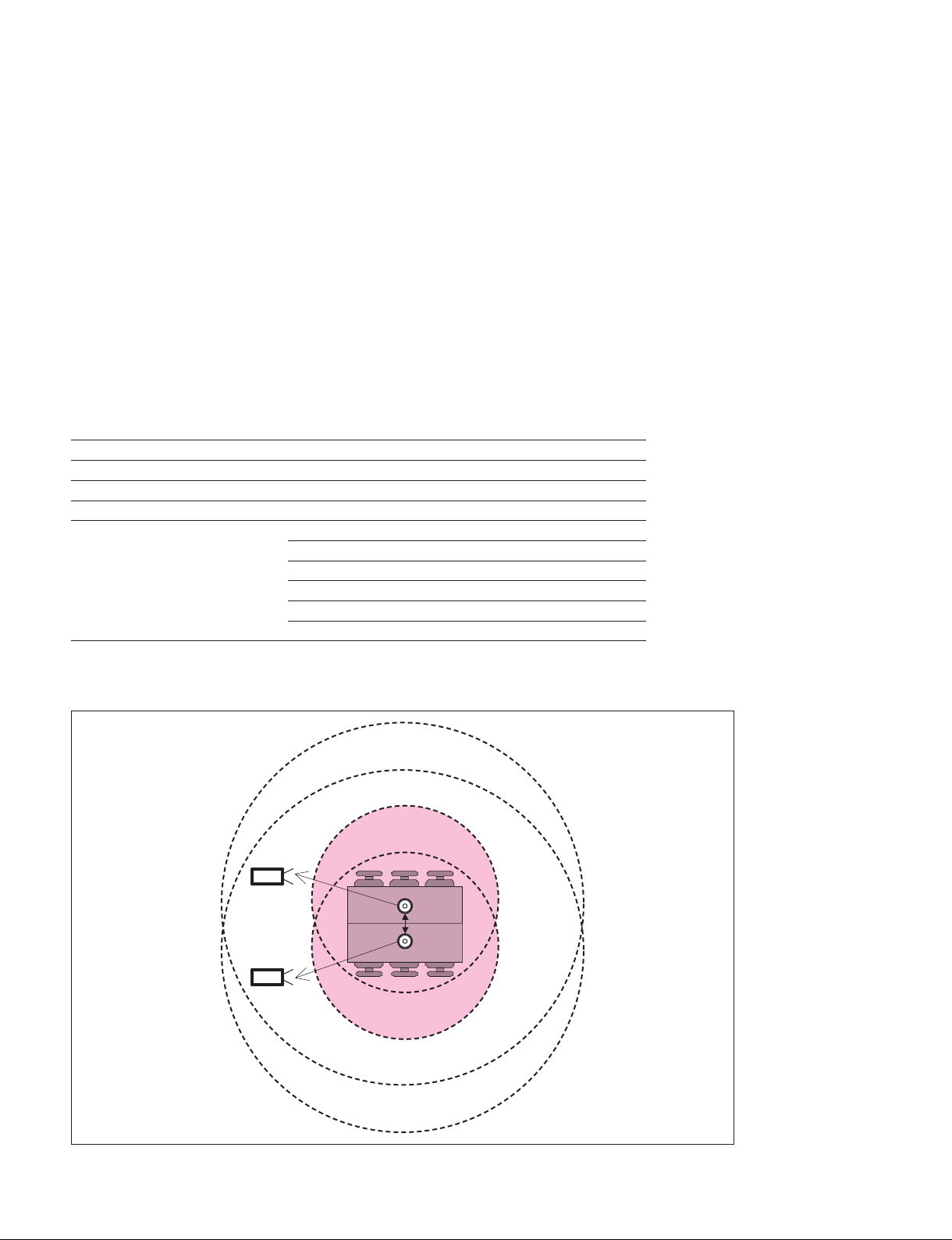
Shooting range of camera unit
Be sure to position the camera and microphone appropriately in your video conferencing room.
represents the shooting area of the camera when the zoom has been extended fully. indicates the
shooting area of the camera when the angling function is fully utilized. Use the measurements shown
below as a guide for the layout of your video conferencing room.
Top view (horizontal range at maximum zoom-out)
1.5 m
(4.92 ft)
100d
100d
4 m
(13.12 ft)
70d
5.6 m (18.37 ft)
Installing the camera on a desk
Place the camera on a fl at surface whenever possible. In extreme circumstances, you may place the cam-
era on an inclined surface provided the inclination does not exceed ?15 degrees, to ensure that the pan/tilt
operates correctly.
1-4
PCS-XG80
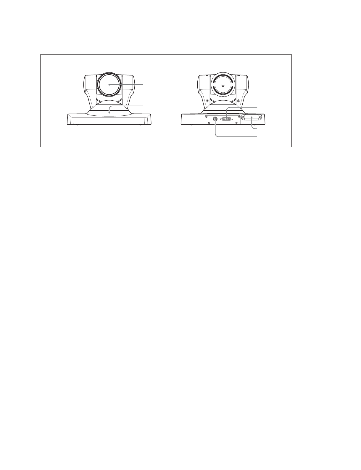
Location and function of camera parts
Front Rear
1
POWER/STANDBY
2
TERMINALVISCA OUT
3
4
5
1 Lens
This is a 10-magnifi cation optical zoom lens.
2 POWER/STANDBY indicator
3 TERMINAL connector
Connect to the CAMERA connector on the PCS-XG Series main unit.
4 Receiver of the RF Remote Commander
The Remote Commander and the PCS-XG Series main unit are paired at the factory.
If the PCS-XG Series main unit is located apart from the Remote Commander, it may not be con-
trolled due to the condition of reception. In this case, perform the procedure to pair the Camera Unit
with the Remote Commander. Refer to the Operating Instructions or “1-1-8. Remote Commander and
Pairing”.
Operable distance of RF-Remote Commander is 10 m (30 ft.). Depending on the circumstances, a
longer operable distance may be possible.
5 VISCA OUT connector
This is used for VISCA connection to 2nd camera. When the 2nd camera is connected with the PCS-
XG Series main unit, connect the VISCA cable from the 1st camera with the VISCA IN of the 2nd
camera. Please refer to “Connecting HD camera as 2nd Camera”. (page 1-9)
PCS-XG80
1-5
Camera cable length
. The PCSA-CXG80 is provided with a 3 m (10 ft.) camera cable as standard.
. If you need to extend the camera cable, refer to “Camera connector pin assignments/cable wiring,”
shown below.
The camera cable line, corresponding to pin numbers 1 to 6, must be made up using coaxial cable (75 Z).
For pin numbers 1 to 6 and 9, the characteristics, structure, and line gauge must be as shown below. You
can extend the camera cable up to a maximum length of 20 m (60 ft.). Test the cable before attempting
to use it.
Camera connector pin assignments/cable wiring
The camera connector pin assignments/cable wiring are as shown below.
Main unit side Camera side
18
18
9
D-sub 15-pin Male
Pin
1
Y_CAM
2
Y_CAM(RET)
3
Pb_CAM
4
Pb_CAM(RET)
5
Pr_CAM
6
Pr_CAM(RET)
7
TXD(for external camera)
8
RXD(for external camera)
9
+19.5 V
10
LVD S_RXD+
11
LVD S_RXD_
12
13
LVD S_TXD+
14
LVD S_TXD_
15
GND
15
(Plug)
Signal
Shell
Coaxial cable 75 Z
1.5C-2 V
Coaxial cable 75 Z
1.5C-2 V
Coaxial cable 75 Z
1.5C-2 V
AWG #24
Twisted pair
AWG #28
Twisted pair
AWG #28
AWG #24
Shield Shield
9
D-sub 15-pin Male
(Plug)
Pin
1
2
3
4
5
6
7
8
9
10
11
12
13
14
15
Signal
Y_CAM
Y_CAM(RET)
Pb_CAM
Pb_CAM(RET)
Pr_CAM
Pr_CAM(RET)
+19.5 V
LVD S_TXD+
LVD S_TXD_
LVD S_RXD+
LVD S_RXD_
GND
Shell
15
1-6
PCS-XG80
Supported cameras
The PCS-XG Series main unit can be connected to the following cameras.
As the 1st camera, PCSA-CXG80, PCSA-CG70, EVI-HD1, BRC-H700/Z700.
As the 2nd camera, EVI-HD1, BRC-H700/Z700. (BRC-Z700 is supported by Ver. 2.0 and later.)
Camera image fl ip
Allows you to rotate the camera image through 180 degrees when the 1st or the 2nd camera is installed in
a ceiling. This is done from the setting menu. For an explanation of the settings, refer to the operating
instructions supplied with the PCS-XG Series models.
This function is supported only by the BRC-H700/Z700. It is not supported by any other camera models.
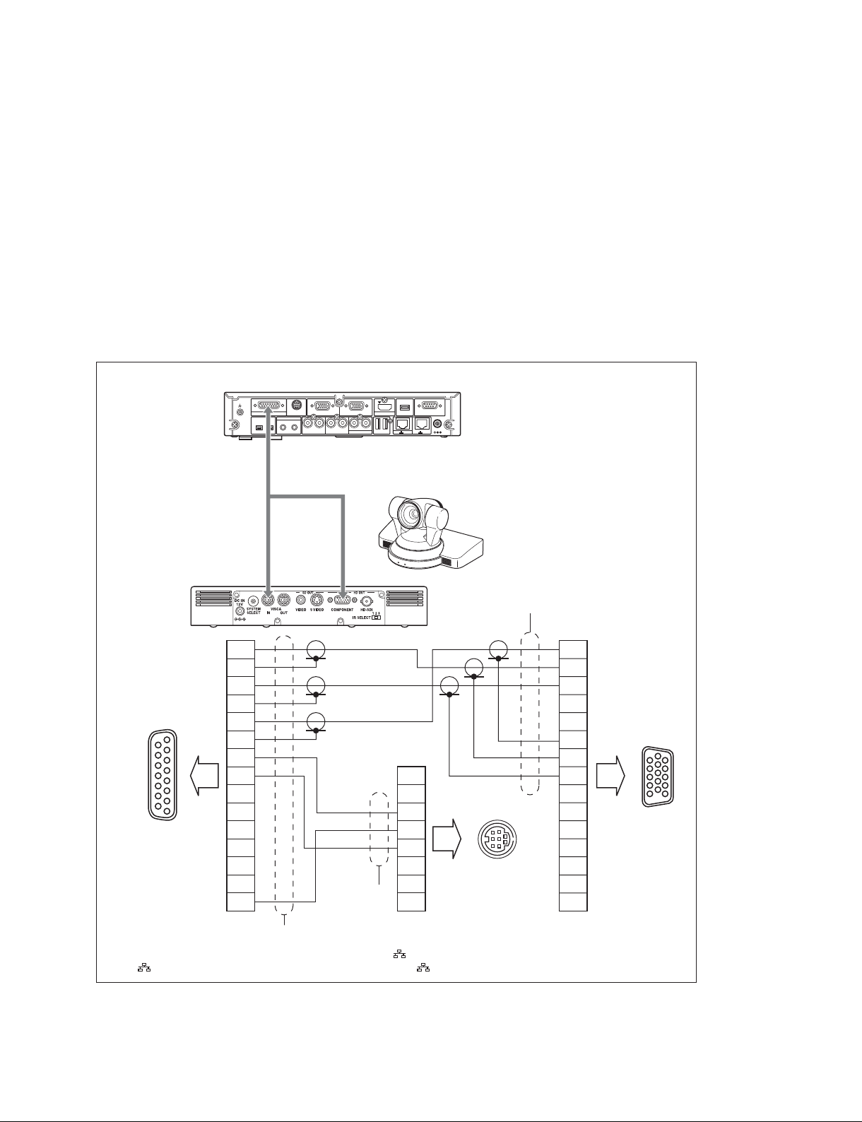
Connecting an EVI-HD1 as 1st camera
Connecting an EVI-HD1 as 1st camera is as below.
1
9
15
8
to PCS-XG Series
main unit
PCS-XG Series main unit rear panel
S VIDEO IN RGB IN RGB OUT HDMI OUT
CAMERA
EC-MIC(A7) MIC(A1/A3)
1(R)
2(L)
1
2
RLRLRL
(PLUG IN POWER)
ISDN UNIT
1
-
EXT-2REC OUTAUDIO OUTAUDIO 1 IN
1
Breakout cable is separately required.
(For detail, contact your local Sony Sales Office/Service Center.)
Breakout
cable
1
2
3
4
5
AWG#28
AWG#28
AWG#28
6
7
8
9
10
11
12
AWG#26
AWG#26
AWG#26
13
14
15
Shell
1
2
3
4
5
6
7
8
*
AUX CONTROL
DC 19.5V
2
EVI-HD1
Shell
1
2
3
4
5
1
6
6
11
7
8
9
3
6
1
7
10
11
15
10
5
to EVI-HD1
12
2
8
5
to EVI-HD1
13
14
15
Shell
* The S VIDEO IN, EC-MIC (A7) 1/2, AUDIO 1 IN, EXT 1/2, and 2 connectors are not available on the PCS-XG55 main unit.
The 1 connector on the PCS-XG80 main unit corresponds to the connector on the PCS-XG55 main unit.
n
When using a camera other than PCSA-CXG80, you should not set the “RF Remote Control Reception”
to “Camera”.
PCS-XG80
1-7
Connecting a BRC-H700/Z700 as the 1st camera
A BRC-H700/Z700 is connected as the 1st camera as described below.
You can use the breakout cable as explained in “Connecting an EVI-HD1 as the 1st camera”.
n
Confi gure the cameras so that a COMPONENT signal is output from their RGB/COMPONENT outputs.
When using a camera other than the PCSA-CXG80, do not set “RF Remote Control Reception” to “Camera”.
PCS-XG Series main unit rear panel
S VIDEO IN RGB IN RGB OUT HDMI OUT
CAMERA
EC-MIC(A7) MIC(A1/A3)
1(R)
2(L)
1
2
RLRLRL
(PLUG IN POWER)
ISDN UNIT
1
-
EXT-2REC OUTAUDIO OUTAUDIO 1 IN
1
Breakout cable is separately required.
(For detail, contact your local Sony Sales
Office/Service Center.)
Breakout
cable
BRC-H700 BRC-Z700
1 2 3 4 5 6 7 8 9
VISCA RS-422
IN VISCA RS-232C OUT
OFF ON
75
EXT SYNC IN
R
DC IN 12V
RGB/COMPONENT
1 2 3
IR SELECT
OFF ON
DATA MIX
*
AUX CONTROL
2
DC 19.5V
PCS-XG Series main unit rear panel
S VIDEO IN RGB IN RGB OUT HDMI OUT
CAMERA
EC-MIC(A7) MIC(A1/A3)
1(R)
2(L)
1
2
RLRLRL
(PLUG IN POWER)
ISDN UNIT
1
-
EXT-2REC OUTAUDIO OUTAUDIO 1 IN
1
Breakout
cable
R
OFF ON
1 2 3 4 5 6 7 8 9
DATA MIX
OFF ON
VISCA RS-422
75
IN VISCA RS-232C OUT S VIDEO
EXT SYNC IN VIDEO
1 2 3
IR SELECT
RGB/COMPONENT
DC IN 12V
*
AUX CONTROL
2
DC 19.5V
* The S VIDEO IN, EC-MIC (A7) 1/2, AUDIO 1 IN, EXT 1/2, and 2 connectors are not available on the PCS-XG55 main unit.
The 1 connector on the PCS-XG80 main unit corresponds to the connector on the PCS-XG55 main unit.
1-8
PCS-XG80
Connecting PCSA-CG70 as 1st camera
When using the PCSA-CG70 as the 1st camera, use the camera cable provided with the camera and
connect this cable to the PCS-XG Series main unit.
n
When using a camera other than PCSA-CXG80, you should not set the “RF Remote Control Reception”
to “Camera”.
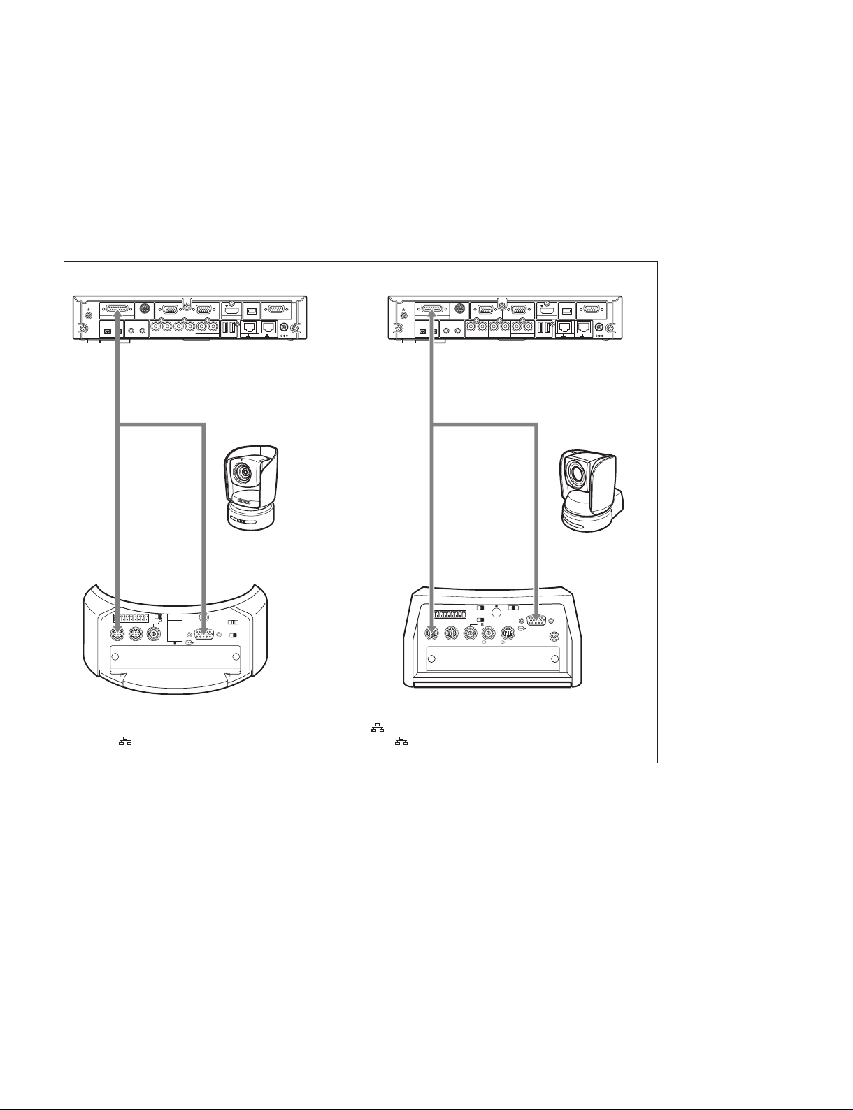
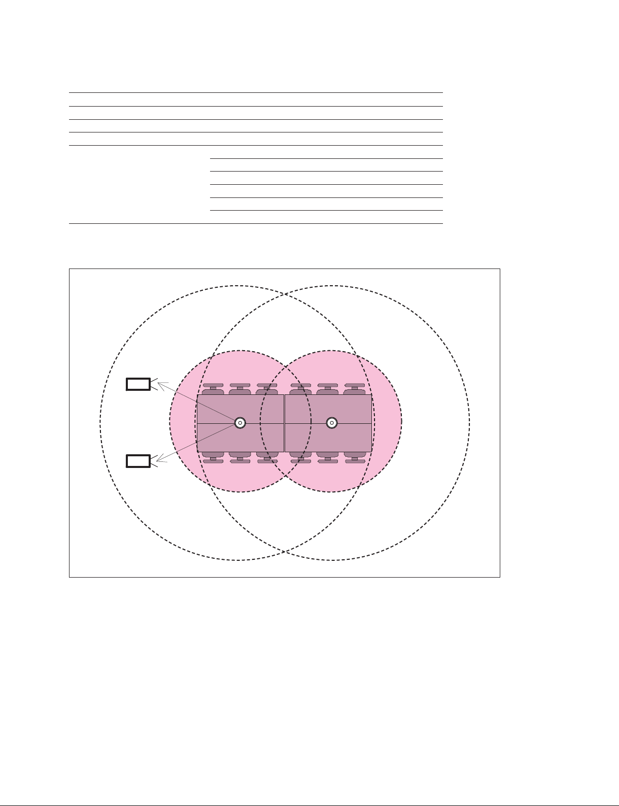
Connecting HD camera as 2nd camera
Connecting HD camera as 2nd Camera is as below.
1st HD camera
2nd HD camera
EVI-HD1,
VISCA cable
* Commercially available
VISCA OUT
TERMINAL
Camera cable
BRC-H700/Z700
(BRC-Z700 is supported
since Ver. 2.0 release)
D-sub 15 pin
* Supplied with camera
/
VIDEO IN AUDIO 2 IN
YPbPrLR
MAINTENANCE
OPEN
VIDEO
(Y, Pb, Pr)
IN
Component cable
* Commercially available
Registration of up to 100 preset camera settings
Up to 100 camera angle/zoom settings can be registered in the preset memory of the PCS-XG Series main
unit.
For an explanation of how to register a preset, refer to the Operating Instructions supplied with the PCSXG Series models.
For both the 1st and 2nd camera, up to 100 settings in total can be stored in the PCS-XG Series main unit.
Ver. 2.0 and later support the saving of thumbnails together with the camera preset settings.
When the preset settings are recalled from the PCS-XG Series main unit, it automatically switches from
the 1st to the 2nd camera (or from the 2nd to the 1st camera).
PCS-XG80
1-9
1-1-3. Microphone Connection
The PCS-A1 and PCSA-A3 microphones can be connected to the input of the PCS-XG Series main unit.
In PCS-XG80/XG80S, the PCSA-A7 can also be used as the input. Up to two PCS-A1 and PCSA-A3
microphones, and up to 80 PCSA-A7 microphones (PCS-XG80/XG80S only, cascaded connection 40 +
cascaded connection 40) can be connected. When you connect the microphone(s) to the PCS-XG Series
main unit, pay careful attention to the positioning guidelines of each microphone described below.
PCS-A1, PCSA-A3 microphone layout
The positioning of the PCS-A1, PCSA-A3 microphones with the PCS-XG Series main unit is the same as
with other models in the PCS series. For details, refer to the Operating Instructions.
Two recommended audio setups (Case1 and Case2) are shown below.
Case1
Microphone PCS-A1 x 2
Suggested number 4 to 6 persons
Input audio mode (microphone) Stereo
Output audio mode (loud speaker) Stereo
Setup menu confi guration Communication: Audio mode MPEG4
Audio 1: Audio Input MIC
Audio 1: Input select (MIC) MIC (A1/A3)
Audio 1: Input Mode Stereo
Audio 1: Output Mode Stereo
Audio 1: Echo canceller On
*1
*1
*1
*1
n *1 “Stereo or Monaural” depends on the setting of Input Mode/Output Mode of far end point.
* Place each loud speaker at least 1.5 m from the PCS-A1.
Loud
speaker
R
1 m to 1.5 m
Loud
speaker
L
0.5 m to 1.5 m
PCS-A1 x 2
3 m or less
1-10
PCS-XG80
Case2
Microphone PCS-A1 x 2
Suggested number 10 to 14 persons
Input audio mode (microphone) Monaural
Output audio mode (loud speaker) Stereo
*1
Setup menu confi guration Communication: Audio mode MPEG4
Audio 1: Audio Input MIC
Audio 1: Input select (MIC) MIC (A1/A3)
Audio 1: Input Mode Monaural
Audio 1: Output Mode Stereo
*1
Audio 1: Echo canceller On
n
*1 “Stereo or Monaural” depends on the setting of Input Mode/Output Mode of far end point.
3 m or less
Loud
speaker
R
Loud
speaker
L
* Place each loud speaker at least 1.5 m from the PCS-A1.
0.5 m to 1.5 m
PCS-A1 x 2
PCS-XG80
1-11
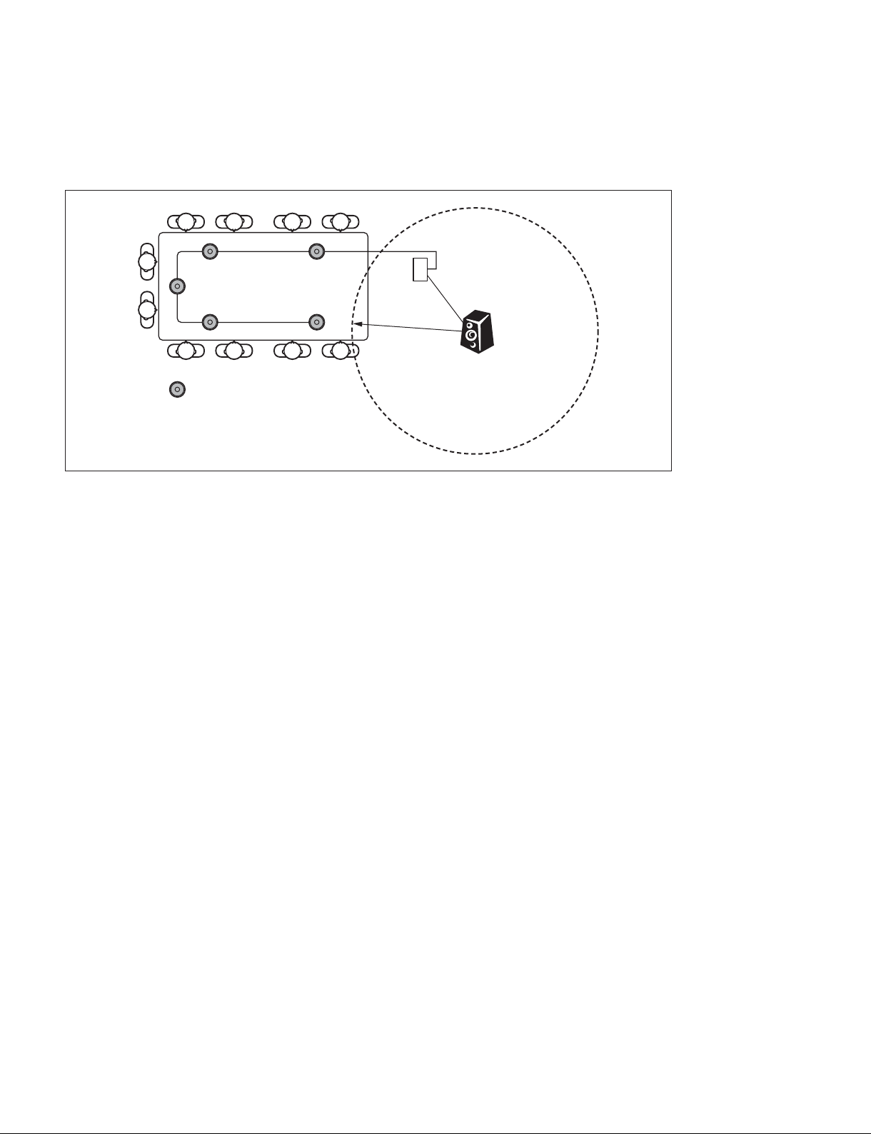
PCSA-A7 microphone layout (PCS-XG80/XG80S only)
Be particularly careful when setting up the PCSA-A7 microphones, referring to the layout shown below.
Position the PCSA-A7 microphone at least 1.5 m (5 ft.) from the loud speaker. Otherwise echo is likely
to be a problem.
PCS-XG80/XG80S
1.5 m
Loud speaker
PCSA-A7
n
Notes on placing the PCSA-A7 microphones
. PCS-XG55/XG55S can not be used.
. Position the microphones about 50 cm (1.6 ft) from the participants.
. For details on the cascade layout and the power supply of the PCSA-A7, refer to the Operating Instruc-
tions.
1-12
PCS-XG80
1-1-4. Audio Specifi cations and Settings
Audio and microphone input/output signal specifi cation
PCS-XG Series main unit rear panel
CAMERA
EC-MIC(A7) MIC(A1/A3)
1
2
S VIDEO IN RGB IN RGB OUT HDMI OUT
1(R)
2(L)
(PLUG IN POWER)
*1
RLRLRL
ISDN UNIT
-
EXT-2REC OUTAUDIO OUTAUDIO 1 IN
1
1
AUX CONTROL
DC 19.5V
2
1 2 345
*1 The S VIDEO IN, EC-MIC (A7) 1/2, AUDIO 1 IN, EXT 1/2, and 2 connectors are not available on the PCS-XG55
main unit.
The 1 connector on the PCS-XG80 main unit corresponds to the connector on the PCS-XG55 main unit.
PCS-XG Series main unit front panel
LAN 1 ALERT LAN 2 ALERT
/
*2
OPEN
VIDEO IN AUDIO 2 IN
YPbPrL R
MAINTENANCE
6
*2 The LAN 2 ALERT LED on PCS-XG80 main unit is labeled ON LINE LED on PCS-XG55 main unit,
and AUDIO 2 IN is labeled AUDIO IN on PCS-XG55 main unit.
No. Connector name Type I/O I/O level
specifi cation
(MAX)
1 EC-MIC (A7)
1/2
2 MIC (A1/A3)
Special 10
pin
mini jack I A1/A3 Special A1/A3 microphone
I/O A7 Special A7 Special 16 kHz Digital I/F
*
L/R
I/O level
specifi cation
(STANDARD)
sensitivity
_33 dBs@34 dBspl
3 AUDIO 1 IN L/R
*
RCA Male I
+9 dBs max
_11 dBs
(max: clip level)
4 AUDIO OUT L/R RCA Male O
5 REC OUT L/R RCA Male O
6 AUDIO 2 IN L/R
**
RCA Male I
+6 dBs _14 dBs
+6 dBs _14 dBs
+9 dBs max
_11 dBs
(max: clip level)
*: It is equipped only for PCS-XG80/XG80S.
**: For PCS-XG55/55S, it is labeled AUDIO IN.
OPEN
Bandwidth
(max)
16 kHz 4.8 kZ
22 kHz 47 kZ or more,
22 kHz 1 kZ or less
22 kHz 1 kZ or less
22 kHz 47 kZ or more,
Specifi cation
(input/output
impedance, etc)
12 V power supply
(Plug in
power 2.5 V)
unbalanced
unbalanced
PCS-XG80
1-13
Notice of external microphone usage
n
For PCS-XG55 main unit, AUDIO 1 IN connector is not equipped and AUDIO 2 IN connector is named
to AUDIO IN connector.
If you connect external microphones with “AUDIO 1 IN” or “AUDIO 2 IN”, you need to use Mic Mixer
and adjust its output level to line level, and this output should be inputted to “AUDIO 1 IN” or “AUDIO 2
IN”.
Adjust the audio level by watching the level meter displayed on the monitor to prevent level clipping. The
level meter can be displayed by setting “On” of “Setup → Home Menu 3 → Audio Level Meter”.
When “AUDIO 1 IN” and “AUDIO 2 IN” are used as AUX which can be selected in Setup menu (Setup
→ Audio 1 → Audio Input), up to 22 kHz input signal can be passed through, but echo canceling function
cannot be used.
When “AUDIO 1 IN” and “AUDIO 2 IN” are used as MIC which can be selected in Setup menu
(Setup → Audio 1 → Audio Input), echo canceling function can be used (but input frequency is
limited.).
For details of Menu settings, refer to “To set up audio input and echo canceller” in 2-2-2.
Adjusting the volume from the remote party’s audio by viewing the volume level of the
Communication System and adjusting the volume on the TV monitor
Before adjusting the volume on the TV monitor, set the volume on the Communication System to the
appropriate position.
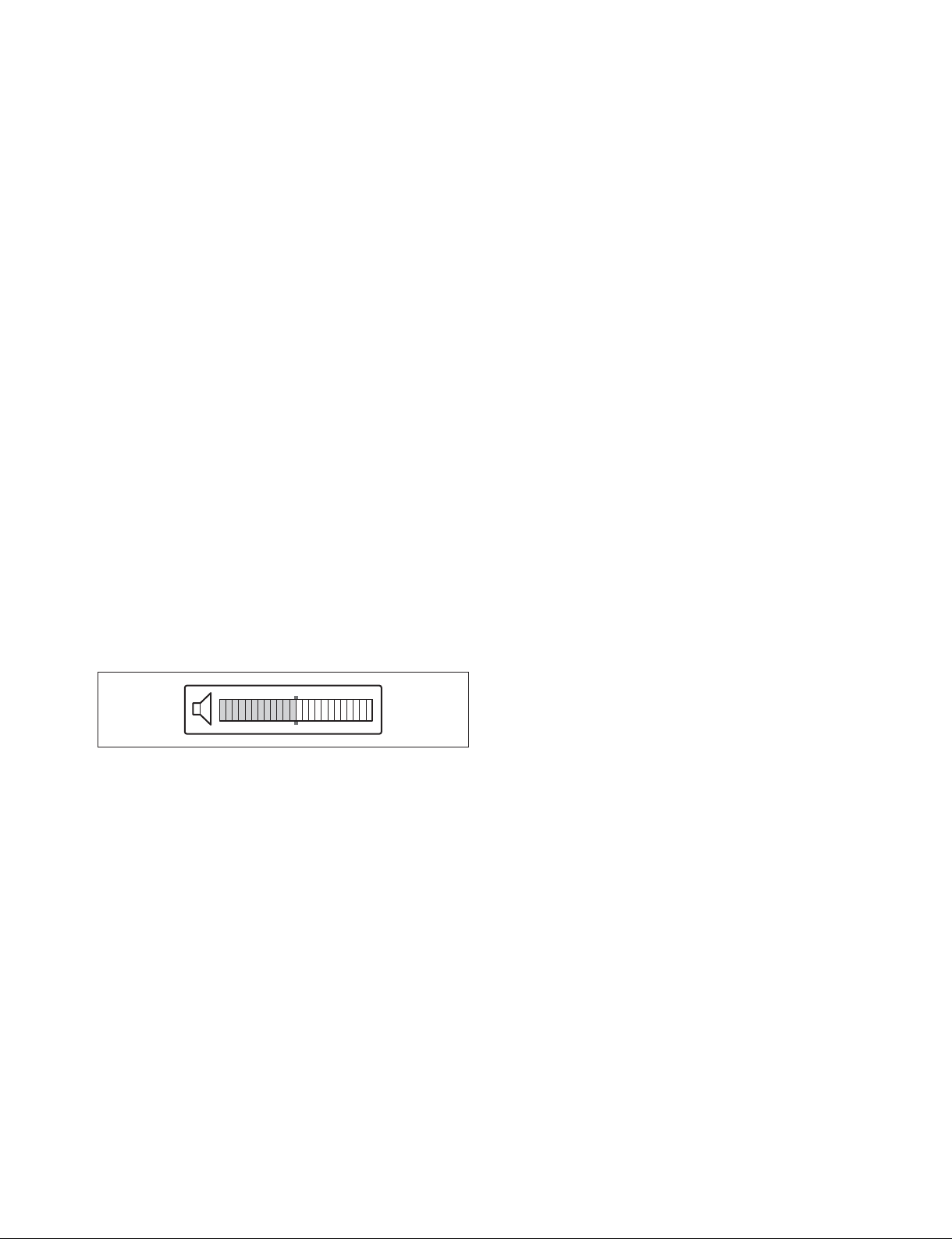
1. To display the volume meter, confi rm its setting. (Setup → Home Menu 3 → Volume)
2. Press the VOLUME [+]/[_] buttons on the remote commander to set the volume level, such that the
bar displayed on the screen is adjusted to the middle position.
3. Adjust the volume on the TV monitor so that you can clearly hear a remote party speaking.
n
Do not activate the TV’s surround sound feature as it may prevent the echo canceller of the Commu-
nication System from functioning properly and thus produce an unexpected sound. During communication, set the volume on the Communication System to the appropriate level, and do not adjust the
volume on the TV monitor.
1-14
PCS-XG80
Setting the audio mode and determining the current mode
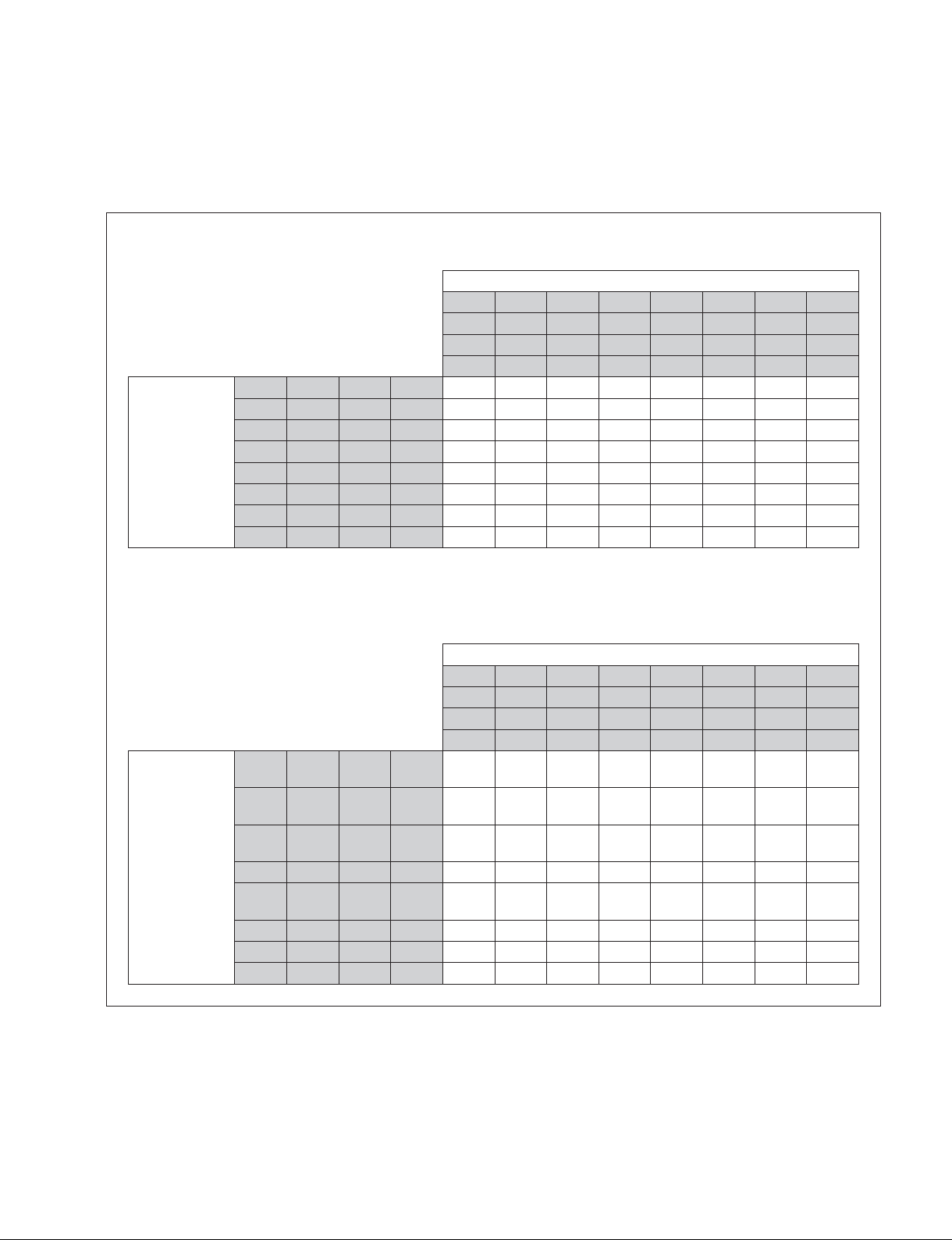
The following table shows the relationship between the “Audio mode” setting under the Communication
Mode menu, confi gured for each terminal at the transmission and reception sides, as well as the negotiated
mode.
When the communication bit rate exceeds 128 kbps:
“Audio mode” setting at Receiver Side (Communication Setup Menu)
MPEG MPEG MPEG MPEG
G.722 G.722 G.722 G.722
G.728 G.728 G.728 G.728
G.711 G.711 G.711 G.711 G.711 G.711 G.711 G.711
MPEG G.722 G.728 G.711
MPEG G.722 G.711
“Audio mode”
setting at Sender
Side
(Communication
Setup Menu)
*1: When the communication bit rate exceeds 768 kbps, the audio mode is AAC Stereo, and when it is between 128kbps-768kbps, AAC Monaural.
MPEG G.728 G.711
G.722 G.728 G.711 G.722 G.722 G.728 G.722 G.711 G.722 G.728 G.711
MPEG G.711
G.722 G.711 G.722 G.722 G.711 G.722 G.711 G.722 G.711 G.711
G.728 G.711 G.728 G.711 G.728 G.728 G.711 G.711 G.728 G.711
G.711 G.711 G.711 G.711 G.711 G.711 G.711 G.711 G.711
*1 *1 *1
*1 *1 *1
*1 *1 *1
*1 *1 *1
G.722
G.722
G.728
G.711
G.722 G.728 G.711
*1
G.722 G.711 G.711
*1
G.711 G.728 G.711
*1
G.711 G.711 G.711
*1
When the communication bit rate is 128 kbps or less:
MPEG G.722 G.728 G.711 G.728
MPEG G.722 G.711
“Audio mode”
setting at Sender
Side
(Communication
Setup Menu)
MPEG G.728 G.711 G.728
G.722 G.728 G.711 G.728 G.722 G.728 G.728 G.711 G.722 G.728 G.711
MPEG G.711
G.722 G.711 G.722 G.722 G.711 G.722 G.711 G.722 G.711 G.711
G.728 G.711 G.728 G.711 G.728 G.728 G.711 G.711 G.728 G.711
G.711 G.711 G.711 G.711 G.711 G.711 G.711 G.711 G.711
“Audio mode” setting at Receiver Side (Communication Setup Menu)
MPEG MPEG MPEG MPEG
G.722 G.722 G.722 G.722
G.728 G.728 G.728 G.728
G.711 G.711 G.711 G.711 G.711 G.711 G.711 G.711
AAC
Mono
AAC
Mono
AAC
Mono
AAC
Mono
AAC
Mono
AAC
Mono
G.728 G.728
AAC
Mono
G.728 G.728
AAC
Mono
G.722
G.711
AAC
Mono
AAC
Mono
AAC
Mono
AAC
Mono
G.722 G.728 G.711
G.722 G.711 G.711
G.711 G.728 G.711
G.711 G.711 G.711
PCS-XG80
1-15
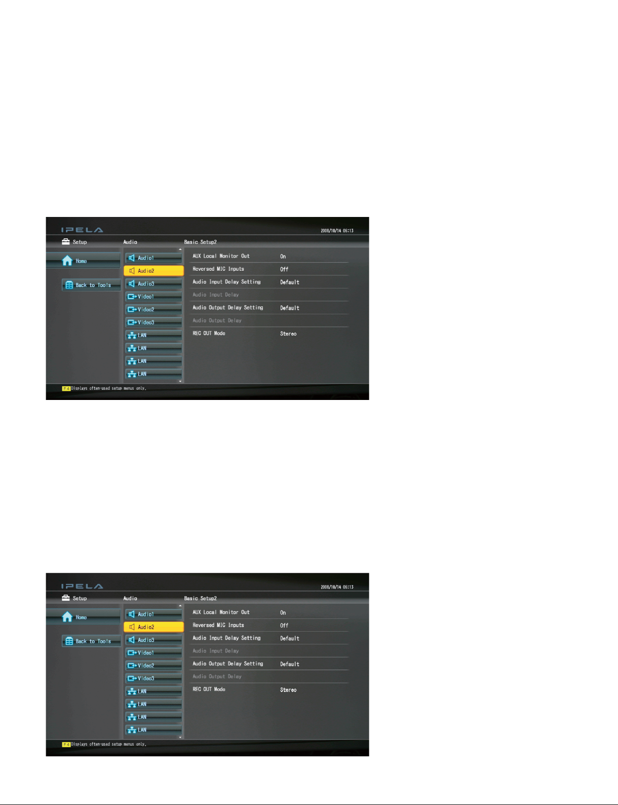
Audio output delay setting
Using the Lip Sync function closely synchronizes the audio and video signals. Even with the Lip Sync
function, however, there still may be a slight time lag, but this can be eliminated by setting a value in
“Audio Output Delay Setting”.
Note that, when the audio signal is fed to an audio system other than that built into the video display, even
using Lip Sync function will not be eliminate the time lag between the audio and video. The time lag can
also be eliminated by setting a delay in “Audio Output Delay Setting”. “Default” is that value with which
the audio is almost synchronized with the video. You can select “Default”, “Default ?50 ms”, and “Default ?100 ms”. When you select “Custom”, an audio output delay between 0 ms and 500 ms can be set as
an absolute delay (Ver.2.01 and later), which has no relation to the Default value.
Audio input delay setting
When there is a time lag between the input audio and input video, a delay can be set in “Audio Input
Delay” to adjust the audio to the video.
An identical delay is set for all the microphones and all the external lines of the PCS-XG Series models.
After setting up the audio and video system to operate with the PCS-XG Series models, setting “Audio
Input Delay”, but then disconnecting the audio and video system from the PCS-XG Series models, restore
the original values or set the “Default” value.
“Audio Delay from Video Picture at Remote Party” contains “Audio Input Delay” set for the local party
and the “Audio Output Delay” set for the remote party. The optimum “Audio Output Delay” setting is
adjusted for each remote party according to the individual usage circumstances, so it is recommended to
use the “Default” value for “Audio Input Delay Setting”.
1-16
PCS-XG80
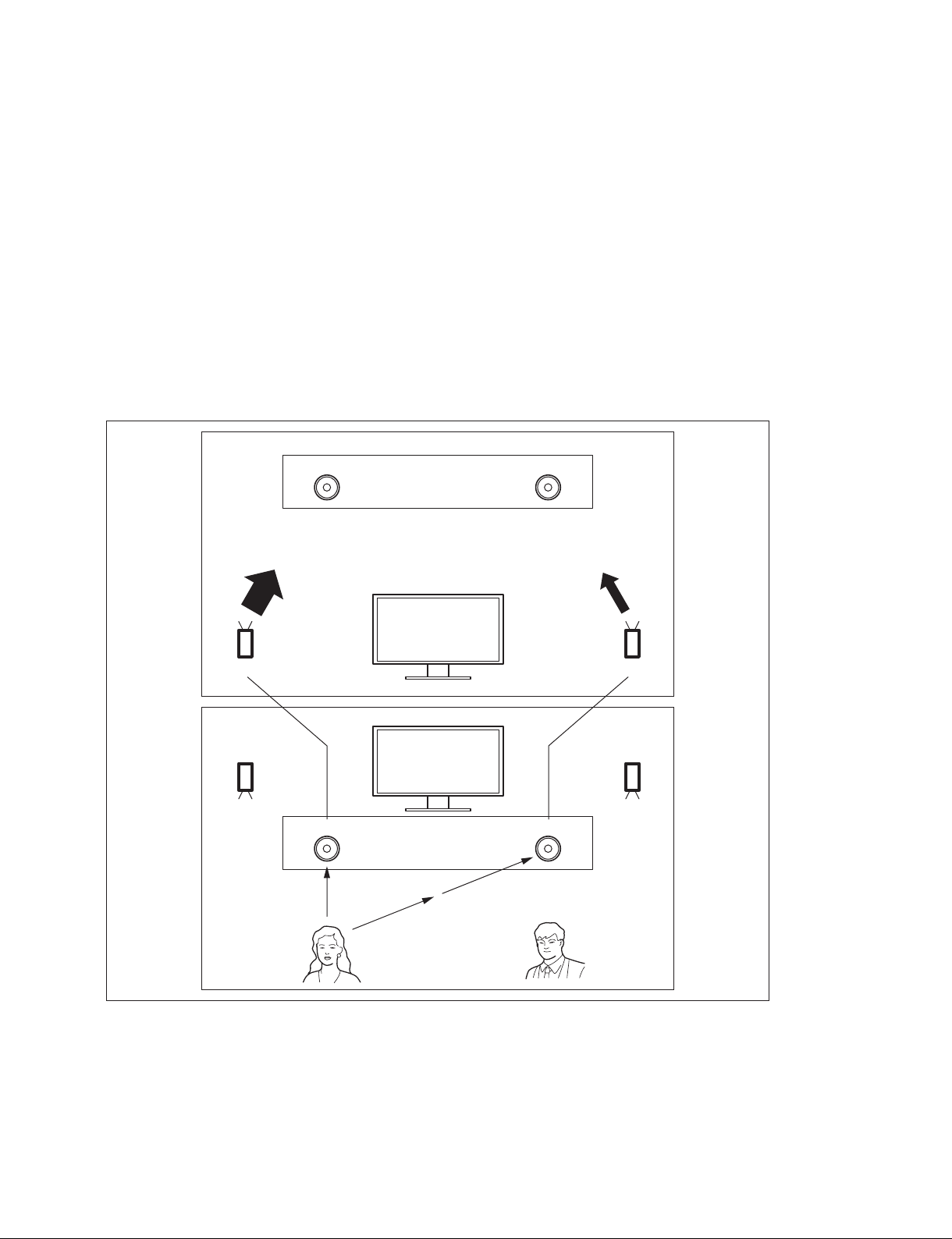
Reversed MIC inputs function
This function allows you to select whether to transmit the audio input from the microphone with right and
left reversed to a remote party. Due to the reversed audio, participants at the remote site can match the
right and left of the camera image and the audio.
n
To reverse the audio, set “Reversed MIC Inputs” of “Audio 2” in the Audio Setup Menu to “On”. (The
initial setting is “Off”.)
You cannot use reversed audio with AUDIO 1 IN/AUDIO 2 IN (PCS-XG80 main unit), or AUDIO IN
(PCS-XG55 main unit) when these inputs are used for AUX, but it can be used with AUDIO 1 IN/AUDIO
2 IN when these inputs are used for MIC. For details on the MIC and AUX settings, refer to “2-2-2 Other
Setup: To set up audio input and echo canceller”.
Right and left can be reversed (Setting of “Audio Input” = MIC)
R
Loud Speaker
Sender side
Receiver side
A
R L
R L
Reversed
L R
Transmitting
PCS-XG Series main unit
L R
B
Camera
PCS-XG Series
main unit
MIC (A1/A3),
AUDIO 1 IN, AUDIO 2 IN
L
Loud Speaker
Monitor
Loud Speaker
L
AB
Loud Speaker
R
n For PCS-XG55 main unit, AUDIO 1 IN connector is not equipped and AUDIO 2 IN connector
PCS-XG80
is named to AUDIO IN connector.
1-17
Right and left not reversed (Setting of “Audio Input” = AUX)
R
Loud Speaker
Sender side
Receiver side
R
R L
R L
R L
Not reversed
PCS-XG Series main unit
Camera
PCS-XG Series
main unit
Transmitting
AUDIO 1 IN, AUDIO 2 IN
L
L
Loud Speaker
Monitor
Loud Speaker
R
AB
Loud Speaker
L
n
For PCS-XG55 main unit, AUDIO 1 IN connector is not equipped and AUDIO 2 IN connector is named
to AUDIO IN connector.
1-18
PCS-XG80
1-1-5. Echo Canceller
Stereo echo canceller’s learning principle
When there is only one sound source, the stereo echo canceller cannot learn four different echo paths,
because:
. The balance of the volume from each of the L and R channels is constant.
. The arrival time interval (Δt) between the sounds from the L and R channels is constant.
To achieve adequate learning by the stereo echo canceller, the sounds from multiple sound sources of the
remote party must reach the echo canceller. This is the essential difference from the monaural echo
Canceller.
If all of the participants stay in their respective fi xed positions and speak, however, the stereo echo cancel-
ler can produce its maximum effect.
If the speaker moves, the stereo echo canceller learning process may take a long time and an echo may
remain.
Receiver side
Microphone Microphone
The stereo echo canceller cannot learn four different paths produced by
two microphones and two speakers, because the two microphones and
the two speakers maintain a constant relation.
Monitor
Loud Speaker
Monitor
Loud Speaker Loud Speaker
Microphone
LR
Sender side
Microphone
Δt
Loud Speaker
AUDIO 1 IN, AUDIO 2 IN and echo canceling function
A stereo echo canceller function is supported for external inputs “AUDIO 1 IN” and “AUDIO 2 IN”.
Refer to “Notice of external microphone usage” in “1-1-4. Audio Specifi cations and Settings” and “To set
up audio input and echo canceller” in “2-2-2. Other Setup”.
n
For PCS-XG55 main unit, AUDIO 1 IN connector is not equipped and AUDIO 2 IN connector is named
to AUDIO IN connector.
PCS-XG80
1-19
Echo canceller function for multipoint connection
For a multipoint connection, the stereo echo canceller function cannot be used because monaural audio
signals are collected. When a multipoint connection is established, the system automatically switches to
the monaural echo canceller function.
1-1-6. Monitor Connection
HDMI monitor and RGB one can be connected with PCS-XG Series main unit.
To connect a monitor or a projector
PCS-XG Series main unit has 3 video output modes. “HDMI” and “RGB” and “HDMI + RGB” are
supported. “HDMI” and “RGB” are same as single monitor mode of current model. “HDMI + RGB” is
same as dual monitor mode of current model.
About HDMI, it enables transmission of high-resolution digital video signals and high-quality digital
audio signals through a single cable.
HDMI cable (3 m) (10 ft) is supplied as accessories.
You can connect to a monitor of any HDMI version.
Maximum length of HDMI cable is limited to 5 m (15 ft.) without a use of repeater.
To extend an HDMI cable beyond its maximum length, HDMI extension cable/adapter, or HDMI repeater
that conforms to HDMI standard is commercially available. Verifi cation is needed before use.
About RGB, “SXGA” or “XGA” or “WXGA” can be selected. (To set up “RGB Monitor Output Format”,
“Setup → Video1 → RGB Monitor Output Format”). Refer to “To set up video output” in 2-2-1.
Monitor
VISCA OUT
TERMINAL
to HDMI IN
to HDMI OUT
S VIDEO IN RGB IN RGB OUT HDMI OUT
CAMERA
EC-MIC(A7) MIC(A1/A3)
1(R)
2(L)
1
2
RLRLRL
(PLUG IN POWER)
to RGB OUT
ISDN UNIT
AUX CONTROL
1
-
DC 19.5V
EXT-2REC OUTAUDIO OUTAUDIO 1 IN
2
1
HDMI cable (supplied)
PCS-XG Series main unit rear panel
*
Monitor, projector, etc.
to RGB IN
D-sub 15 pin cable (Commercially available)
* The S VIDEO IN, EC-MIC (A7) 1/2, AUDIO 1 IN, EXT 1/2, and 2 connectors are not available on the PCS-XG55
main unit.
The 1 connector on the PCS-XG80 main unit corresponds to the connector on the PCS-XG55 main unit.
n
Using a monitor with DVI:
DVI-HDMI conversion adaptor/cable (commercially available) is required.
Use a conversion adaptor/cable that conforms to HDMI standard.
Verifi cation is needed before use.
DVI cannot transmit digital audio signal through a single cable, so connect the audio output to the loudspeaker input.
1-20
PCS-XG80
Notes on monitor connections and settings
. When you wish to use an HDMI monitor, it must have a 1080i INPUT connection. A monitor without
the 1080i INPUT connection cannot display the menu.
. When you are using a 60-Hz monitor but the “Video1 → Frequency” is set to “50 Hz”, the menu cannot
be displayed on the monitor and you cannot perform any menu operations.
In this case, access the Communication System by using a Web Browser and restore “Frequency” under
“Video:Basic” in the Setup Menu to “60 Hz”.
Otherwise, restore the Frequency value to 60 Hz by connecting a serial cable to the AUX CONTROL port on the
rear of the Communication System and sending an external control command “setup save video frequency-60hz”.
. When “Video1 → Monitor Output” is set to “HDMI + RGB”, the picture from the camera or PC con-
nected to the RGB IN connector is displayed on the RGB monitor. If only the RGB monitor is connected, you cannot perform any menu operations.
In this case, also connect an HDMI monitor.
If an HDMI monitor is not available, access the Communication System by using a Web Browser and
set “Monitor Output” under “Video:Basic” in the Setup Menu to “RGB”.
Otherwise, restore the “Monitor Output” to “RGB” by connecting a serial cable to the AUX CONTROL port on
the rear of the Communication System and sending an external control command “setup save video monout-rgb”.
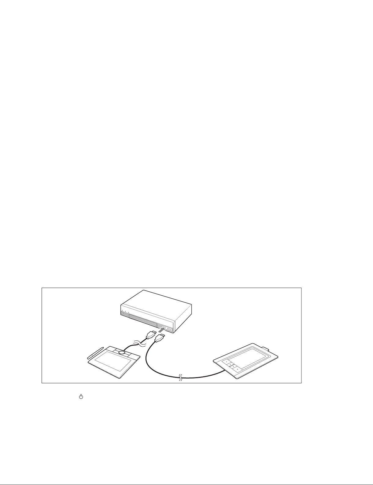
1-1-7. Pen Tablet
To use the function of Drawing and Pointing in communication, the pen tablet is needed.
To connect a Pen Tablet
1. Pen tablet is not a supplied accessories. So, prepare a pen tablet separately. About the pen tablet, refer
to the Notes as shown below.
2. Turn off the main unit.
3. Connect the pen tablet to the TABLET connector (PCS-XG80 main unit)/OPTION connector (PCSXG55 main unit) on the front panel of the main unit before power-on.
To TABLET connector (PCS-XG80 main unit)/
OPTION connector (PCS-XG55 main unit)
1.5 m (5 ft.) supplied cable with
“Bamboo” (MTE-450) or
cable connected with
“Bamboo” (CTH-460)
“Bamboo” (MTE450)
“Bamboo” (CTH-460)
4. Press the I/ (power) switch to turn on the main unit.
m
. Supported TABLET models are Wacom “Bamboo” (MTE450) and “Bamboo” (CTH-460). “Bamboo”
(CTH-460) is usable in Ver.2.1 and later. When you use it, perform the upgrade to Ver.2.1 and later.
. The cable length which is supplied with “Bamboo” (MTE450) is 1.5 m (5 ft.). The USB cable length of
“Bamboo” (CTH-460) is 1.5 m (5 ft.).
. If you use another longer cable except the attached one, use the USB Hub, or extend the USB cable,
perform the verifi cation before use.
PCS-XG80
1-21
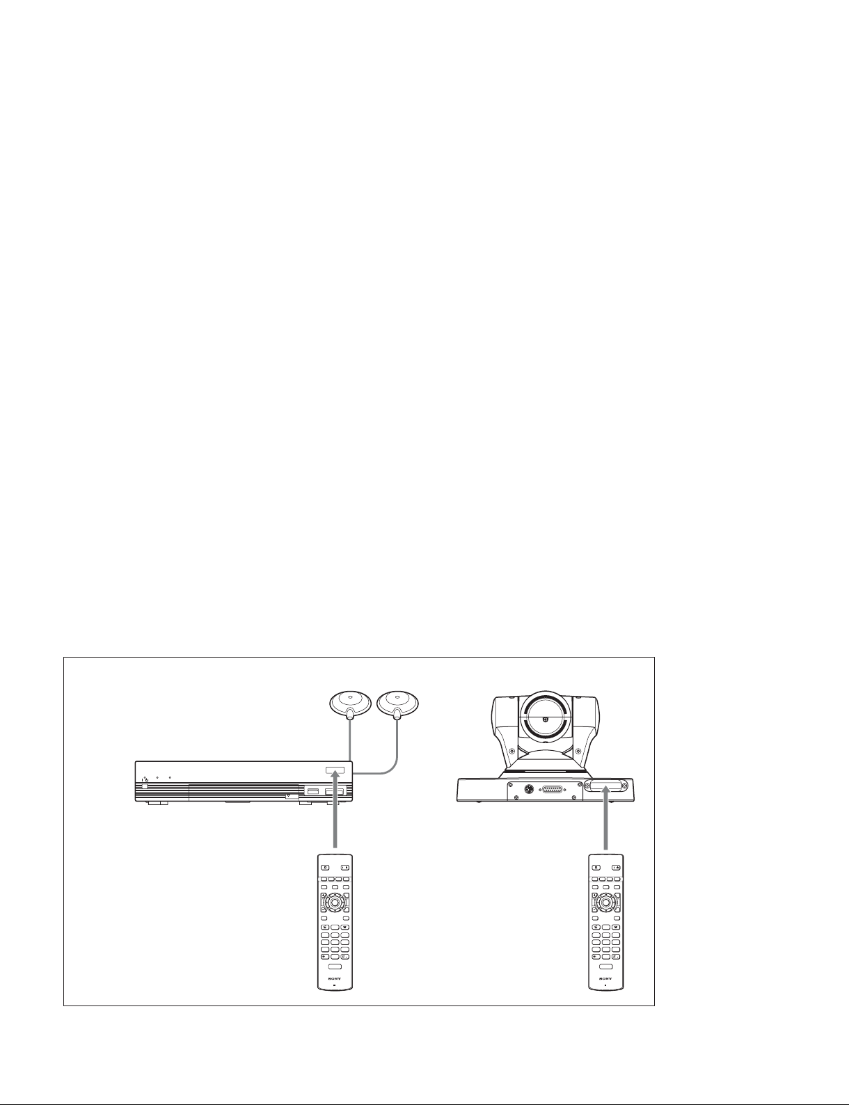
1-1-8. Remote Commander and Pairing
RF (Radio Frequency) Remote Commander
The supplied Remote Commander controls the main unit (or its Camera Unit) by using the radio frequency of 2.4 GHz.
The remote commander can be paired with either the main unit or its Camera Unit, such that this remote
commander will not accidentally operate another main unit or its Camera Unit.
The range of the remote commander is 10 m (30 ft.). Depending on the circumstances, a longer range may
be possible.
Up to fi ve RF remote commanders can be paired with one PCS-XG Series models.
The oldest pairing information is overwritten when a sixth remote commander is paired.
When an additional remote commander is paired, a new commander which is a replacement for a lost or
broken one is paired, or the RF remote control reception (main unit or Camera Unit) is changed because,
for example, it has failed, pairing must be performed. The pairing procedure is as described below.
Before the Pairing Procedure
The Remote Commander and the main unit are paired at the factory.
If the reception conditions are diffi cult, you can change the pairing target from the main unit to the Cam-
era Unit. (Refer to “RF Remote Control Reception” in 2-2-2.)
When you are performing pairing, turn off any other main unit that may be located nearby.
If another main unit is turned on, the Remote Commander may be paired with that main unit (or its Camera Unit).
The remote commander can be paired with the main unit or its Camera Unit, so that this remote commander cannot accidentally operate another main unit or its Camera Unit.
When you are performing the pairing procedure, aim the head of the Remote Commander at the main unit
(or receiver on the Camera Unit). The distance between the Remote Commander and the main unit must
not exceed 20 cm (8 inches).
When performing the pairing procedure
/
Within 20 cm (8 inch) Within 20 cm (8 inch)
PRESENTATION
/
F1 F2 F3 F4
LAYOUT
VIDEO INPUT CAMERA
VOLUME ZOOM
T
ENTER
W
RETURN
TOOLS
BACK
SPACE
CONNECT
DISCONNECT
ABC DEF
123
GHI JKL MNO
456
WXYZ
PQRS TUV
789
TONE DOT
0
ON/OFF
MIC
PCS-RF1
RF
VISCA OUT
TERMINAL
PRESENTATION
F1 F2 F3 F4
VIDEO INPUT CAMERA
LAYOUT
VOLUME ZOOM
ENTER
RETURN
BACK
SPACE
CONNECT
ABC DEF
123
GHI JKL MNO
456
PQRS TUV
789
TONE DOT
0
ON/OFF
MIC
PCS-RF1
RF
DISCONNECT
/
T
W
TOOLS
WXYZ
1-22
PCS-XG80
Pairing Procedures
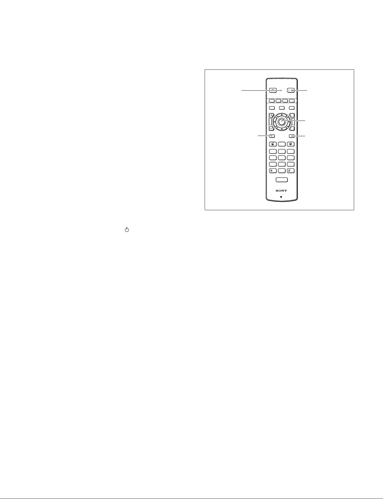
To pair the main unit or Camera with the Remote Commander again, follow the procedure below.
1. Turn on the main unit.
2. Under “General 1” of the General setup menu, set “RF
Remote Control Reception” to “System” or “Camera”.
Refer to “RF Remote Control Reception” in 2-2-2
3. Within three minutes of turning the power on, position
the Remote Commander close to the main unit (within
20 cm (8 inches)), and then press the [RETURN] and
[TOOLS] buttons at the same time. The LED indicator fl ashes rapidly.
LED
[RETURN] button
PRESENTATION
F1 F2 F3 F4
LAYOUT
VIDEO INPUT CAMERA
VOLUME ZOOM
ENTER
RETURN
BACK
SPACE
CONNECT
4. Press the [ENTER] button on the Remote Command-
ABC DEF
er.
If the LED indicator fl ashes more slowly, pairing
between the units has succeeded.
123
GHI JKL MNO
456
PQRS TUV
789
TONE DOT
0
ON/OFF
MIC
m
PCS-RF1
. If pairing fails, the LED indicator on the Remote Com-
RF
mander will continue to fl ash rapidly. In this case, press
the [ENTER] button on the Remote Commander and try
the pairing operation again.
. To cancel pairing, press the I/ (power) switch on the
main unit.
. Once pairing is established between the units, it will not
be erased even when the batteries in the remote commander are replaced.
. If you have lost the remote commander or if it no longer
works, obtain a replacement and perform pairing again.
. When the camera unit is to be paired with the Remote
Commander and then installed in a high location, perform the pairing before the installation.
/
T
W
TOOLS
DISCONNECT
WXYZ
I/O button
[ENTER] button
[TOOLS] button
PCS-XG80
1-23
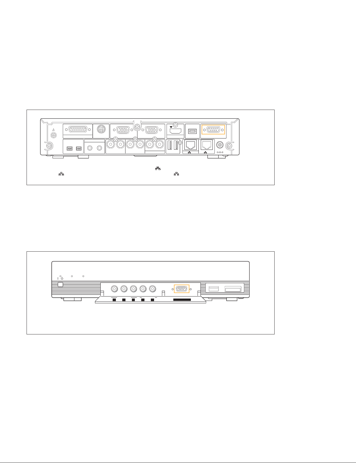
1-1-9. Two Serial Ports on PCS-XG Series Main Unit
Rear and front ports
Unlike previous models, the PCS-XG Series main unit has two serial ports. One is on the front of the
main unit and is intended for maintenance. The other is on the rear and is for external control. The baud
rates and the locations of the ports are as shown below.
Rear: AUX CONTROL port
CAMERA
EC-MIC(A7) MIC(A1/A3)
1
S VIDEO IN RGB IN RGB OUT HDMI OUT
1(R)
2
2(L)
(PLUG IN POWER)
RLRLRL
ISDN UNIT
-
EXT-2REC OUTAUDIO OUTAUDIO 1 IN
1
AUX CONTROL
DC 19.5V
2
1
The S VIDEO IN, EC-MIC (A7) 1/2, AUDIO 1 IN, EXT 1/2, and 2 connectors are not available on the PCS-XG55 main
unit. The 1 connector on the PCS-XG80 main unit corresponds to the connector on the PCS-XG55 main unit.
For external control
. bps: 38400
. Data bit: 8
. Parity: None
. Stop bit: 1
Front: MAINTENANCE port
LAN 1 ALERT LAN 2 ALERT
/
OPEN
VIDEO IN AUDIO 2 IN
YPbPr L R
MAINTENANCE
OPEN
The LAN 2 ALERT LED on PCS-XG80 main unit is labeled ON LINE LED on PCS-XG55 main unit,
and AUDIO 2 IN is labeled AUDIO IN on PCS-XG55 main unit.
For taking a debug log/For engineering maintenance
. bps: 115200
. Data bit: 8
. Parity: None
. Stop bit: 1
1-24
PCS-XG80
 Loading...