

Sony Ipela PCS-XG100, Ipela PCS-XG100S, Ipela PCS-XG77, Ipela PCS-XG77S Installation Manual
LAN1-ALERT-LAN2 ONLINE
CAMERA
1080 60P
I
N
O
U
T
HDMI
DVI-I OUT ISDN UNIT AUX CONTROL MAINTENANCE
REC OUT
LRLRLRLR
AUDIO OUTAUDIO 2 INAUDIO 1 IN
MIC(A1)
1(R) 2(R) 3(R) 4(L) 5(L)26(L)
DVI-I 1 DVI-I 2(PC)
HDMI-2
HDMI-1
1
HD Visual Communication System
PCS-XG100/XG77/XG100S/XG77S
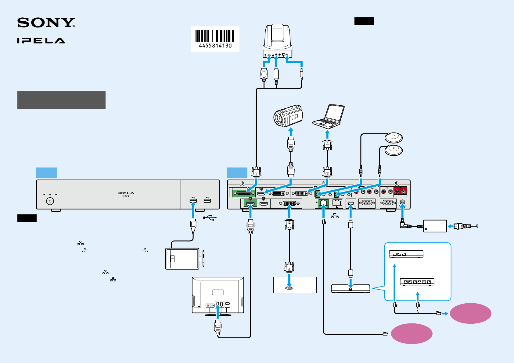
Installation Guide
Connections
1)
Supplied
2)
Supplied (two PCS-A1 microphones are supplied with the
PCS-XG100/XG100S, and one is supplied with the PCS-XG77/XG77S)
3)
Supplied with the PCS-XG100/XG77
4)
Supplied (Japan only)
5)
Not supplied
6)
Output to HDMI monitors under default settings. When outputting to a non-HDMI monitor,
refer to the “To change the ‘Monitor Output’ setting” section on the reverse side.
Front Rear
Notes
The PCS-XG77/XG77S is not equipped with the following connectors ˎ
and indicators:
HDMI IN, HDMI-2 OUT, and 2 connectors, and LAN 2 ALERT indicator
On the PCS-XG77/XG77S, the ˎ 1 connector is named the
connector, and the LAN 1 ALERT indicator is named the LAN ALERT
indicator.
Normally, connect the UTP cable to the ˎ 1 connector (indicated in
green). If the UTP cable is connected to the 2 connector, some of the
functions of the system may be restricted.
For details, refer to the Operating Instructions supplied with the system.
The REC OUT jack is used to make an audio recording of a ˎ
communication, for example. It is not used during regular
communication.
We recommend using Sony’s HDMI cable. ˎ
© 2013 Sony Corporation
Printed in China
to
(USB) port
TV monitor
4-455-814-13 (1)
Pen tablet
5)
(Wacom)
5) 6)
to HDMI IN
SRG-120DH
HD Camera Unit
to HDMI to VISCA
IN
Camera cable
1)
VCR, etc.
to HDMI-1
OUT
DVI cable
Projector, etc.
HDMI cable
1)
HDMI
cable
to HDMI INto CAMERA
OUT
to DC 12V
Computer
5)
5)
Notes
3)
DVI cable
to DVI-I 2
(PC) IN
to
1
ISDN unit
UTP cable (category 6,
straight)
Be sure to turn off all the equipment before making any connections. ˎ
Do not connect/disconnect the camera cable, interface cable, or pen ˎ
tablet with the power on. Doing so may damage the camera unit,
Communication System, or ISDN unit.
For safety, do not connect the 1000BASE-T connector to a network ˎ
that will apply excess voltage to this connector.
When used with an ISDN unit for the first time, ˎ the
Communication System may automatically upgrade the software
of the connected equipment. Follow the instructions on the
monitor screen to upgrade the software. Do not turn off the
Communication System or disconnect the cable during upgrade.
Doing so may cause a malfunction of the system.
ISDN support is planned for version 2.0. ˎ
5)
to ISDN UNITto DVI-I
Interface
cable
(supplied
with ISDN
unit)
to TERMINAL
5)
5)
PCS-A1 microphone
Connecting two microphones allows pickup
of stereo sound.
to MIC (A1) 1 (R) / 4 (L)
to DC 19.5 V
PCSA-B384S
5)
to ISDN 1 to 3
or
PCSA-B768S
to ISDN 1 to 6
ISDN modular cable
LAN
AC adaptor
5)
5)
2)
Power cord
to power outlet
1)
ISDN
line
Continued on
reverse side
4)
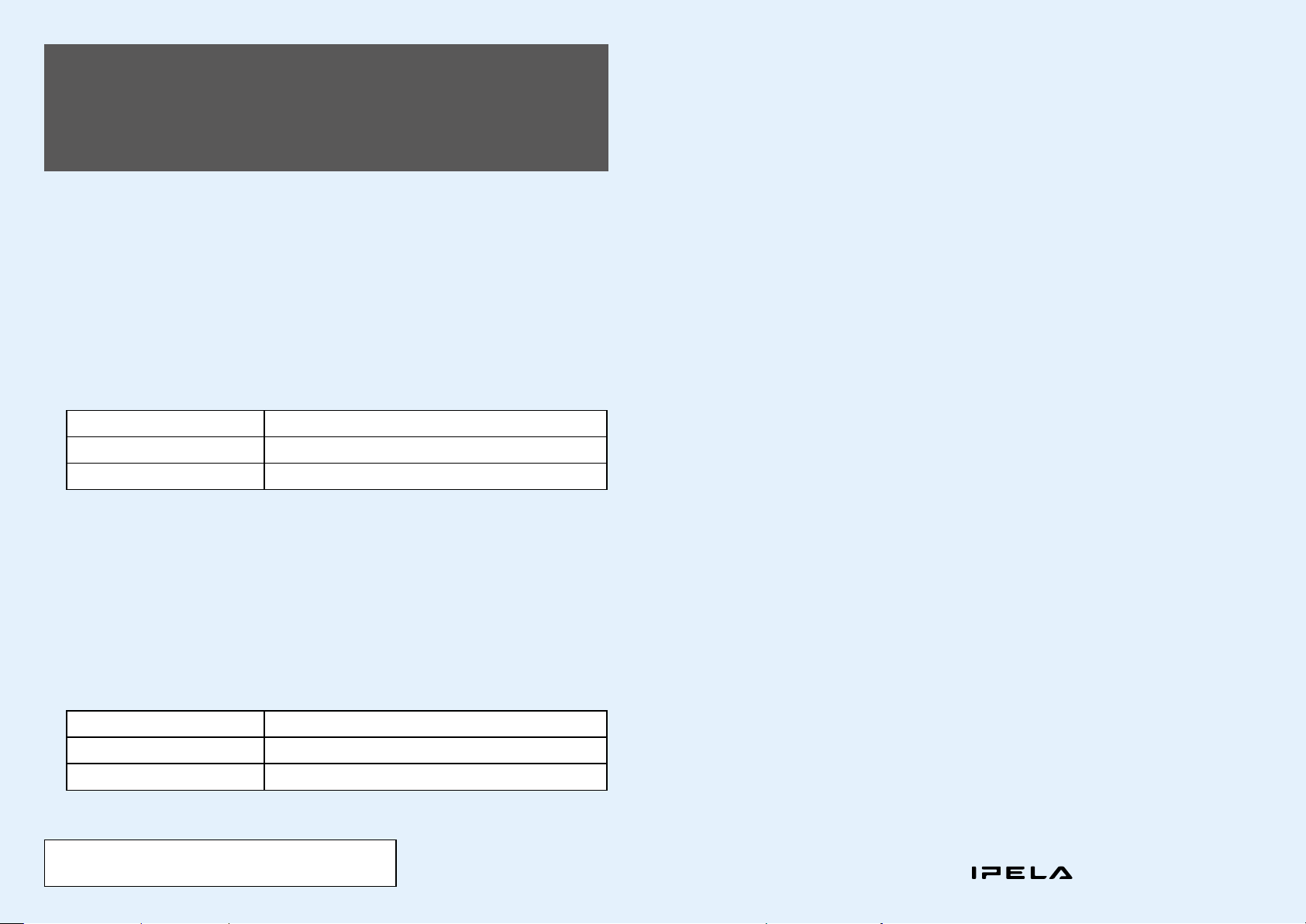
Changing the “Monitor Output” and
“Frequency” Settings with the Remote
Commander
If the “Monitor Output” and “Frequency” settings in the Video setup menu are configured incorrectly, pictures
will not be displayed on the monitor. In such cases, use the (power) switch on the Communication System
and the buttons on the Remote Commander to configure the correct settings.
To change the “Monitor Output” setting
After verifying that the (power) switch indicator on the system is lit, perform the following.
Press the (power) switch on the Communication System.
Within five seconds after you pressed the switch, press the buttons on the
Remote Commander as follows, based on the desired “Monitor Output.”
Desired “Monitor Output” On the Remote Commander, press:
HDMI 1
DVI-I OUT
The “Monitor Output” setting is changed, and the picture appears on the monitor connected to the system.
VIDEO INPUT button (once) Number button 3 (three times)
VIDEO INPUT button (once) Number button 4 (three times)
To change the “Frequency” setting
After rebooting the system and verifying that the (power) switch indicator changes from blinking to
remaining steadily lit, perform the following.
Press the (power) switch on the Communication System.
Within five seconds after you pressed the switch, press the buttons on the
Remote Commander as follows, based on the desired “Frequency.”
Desired “Frequency” On the Remote Commander, press:
60 Hz
50 Hz
The “Frequency” setting is changed, and the system reboots.
Note
The Remote Commander cannot be paired with cameras.
VIDEO INPUT button (once) Number button 1 (three times)
VIDEO INPUT button (once) Number button 2 (three times)
“IPELA” and
are trademarks of Sony Corporation.
 Loading...