

Sony Ipela PCS-XC1, PCS-XC1 Operating Instructions Manual

4-545-839-11 (1)
HD Visual
Communication
System
Operating Instructions (Version 1.0)
Before operating the unit, please read this manual thoroughly and retain it for
future reference.
PCS-XC1
© 2014 Sony Corporation

Table of Contents
Chapter 1: Installation and Preparation
Using This Manual .....................................................................................................7
Features ......................................................................................................................8
System Components ................................................................................................10
Basic System Components .................................................................................10
Optional Equipment ...........................................................................................11
System Configuration ..............................................................................................12
System Configuration via a LAN .......................................................................12
System Configuration via a SIP .........................................................................13
System Installation ...................................................................................................14
Desktop Installation ...........................................................................................14
Using a Tripod ....................................................................................................14
Using Fixing Screws ..........................................................................................15
System Connections .................................................................................................16
System Connection via a LAN ...........................................................................17
System Connection via a SIP .............................................................................18
Preparing the System ...............................................................................................19
Inserting Batteries into the Remote Commander ...............................................19
Pairing the Remote Commander with the Unit ..................................................20
Turning the Unit On/Off ..........................................................................................22
Turning On .........................................................................................................22
Standby Mode Function .....................................................................................23
Setting the Unit to Standby Mode ......................................................................23
Turning Off ........................................................................................................24
Adjusting the Volume on the TV Monitor .........................................................24
Setting Up the System Immediately after the
Installation – Initial Setup Wizard ...........................................................................26
Using the Menus ......................................................................................................29
Identifying the Home Menu ...............................................................................29
Operation Using the Menu .................................................................................35
Entering Characters Using the Remote Commander .........................................38
Entering Characters Using the On-Screen Keyboard .........................................39
Chapter 2: Registration and Setup for System
Administrators
Registering Local Information .................................................................................41
Opening the Setup Menu ....................................................................................41
2

Line Interface Setup Menu ................................................................................ 45
Dial Setup Menu ................................................................................................ 45
Answer Setup Menu .......................................................................................... 45
Communication Setup Menu ............................................................................. 45
Audio Setup Menu ............................................................................................. 47
Video Setup Menu ............................................................................................. 49
LAN Setup Menu .............................................................................................. 49
QoS Setup Menu ............................................................................................... 51
TOS Setup Menu ............................................................................................... 53
SIP Setup Menu ................................................................................................. 53
Annotation Setup Menu ..................................................................................... 54
General Setup Menu .......................................................................................... 54
Home Menu Setup Menu .................................................................................. 56
Administrator Setup Menu ................................................................................ 57
Encryption Setup Menu ..................................................................................... 62
Shared Phone Book Setup Menu ....................................................................... 63
Displaying the Machine Status ............................................................................... 64
Displaying the Machine Status Menu ............................................................... 64
Machine Information ......................................................................................... 66
Peripheral Status ................................................................................................ 66
Communication Mode Status ............................................................................ 66
LAN Line Status ................................................................................................ 67
Network Routing Check .................................................................................... 67
Restrictions on the Use of IPv6 ............................................................................... 68
Setting Up the Network Configurations .................................................................. 69
LAN Connection via DHCP .............................................................................. 69
LAN Connection through a Router ................................................................... 70
LAN Connection through a Gatekeeper ............................................................ 71
LAN Connection through NAT ......................................................................... 72
LAN Connection with H.460 Firewall Traversal .............................................. 73
LAN Connection Using PPPoE ......................................................................... 75
About the Network Routing Check ......................................................................... 76
Adding Optional Software ...................................................................................... 77
Confirming that the Installation of the Optional Software is Complete ............ 78
Chapter 3: Basic Connection
Starting a Connection by Calling a Remote Party .................................................. 79
Turning On the Power ....................................................................................... 79
Calling a Remote Party by Using the Connect Menu ....................................... 80
Calling a Remote Party by Entering Their Address or Number Directly (Direct
Dial) ....................................................................................................... 81
Calling a Remote Party Using the One-Touch Dial Buttons ............................. 83
3

Calling a Remote Party by Selecting Them in the History List .........................84
Calling a Remote Party Registered in the Phone Book ......................................85
Calling a Remote Party Not Registered in the Phone Book ...............................87
Receiving a Call from a Remote Party ....................................................................89
Answering Calls (Manual/Auto Answer Mode) ................................................89
Answering a Call from a Remote Party .............................................................89
Ending the Connection .............................................................................................91
Registering a Remote Party – Phone Book ..............................................................92
Registering a New Remote Party .......................................................................92
Editing the Contents of the Phone Book ............................................................95
Copying a Registered Party in the Phone Book .................................................95
Deleting the Registered Remote Party ...............................................................95
Creating a Group in the Phone Book (Group Edit) ............................................96
Creating a Private Phone Book ..........................................................................98
Using the Shared Phone Book ..........................................................................100
Adjusting the Sound ...............................................................................................102
Adjusting the Volume of the Received Sound .................................................102
Turning Off the Sound Momentarily – Muting Function ................................102
Turning Off the Sound on Answering – Mic on Answer Function ..................103
Synchronizing Audio and Video – Lip Sync Function ....................................103
Reducing Echo – Echo Canceller .....................................................................103
Adjusting the Camera ............................................................................................104
Adjusting the Camera Angle and Zoom ...........................................................104
Adjusting the Brightness ..................................................................................105
Using the Preset Function ................................................................................107
Adjusting the Camera in the Detailed Setup Menu ..........................................109
Selecting the Input Picture and Sound ...................................................................112
Switching the Displayed Picture between the Local and Remote Pictures ......112
Selecting the Input Picture ...............................................................................112
Selecting the Video Input Using the F1 to F4 (Function) Buttons on the
Remote Commander .............................................................................113
Switching the Picture from the Remote System ..............................................113
Switching the Picture Displayed on the Monitor Screen .......................................114
Capturing the Screen ..............................................................................................116
Chapter 4: Connection with Optional Equipment
Using a Tools Menu ...............................................................................................118
Using the Computer Picture for Presentation ........................................................120
Connecting a Computer ....................................................................................120
Making a Presentation ......................................................................................120
Streaming a Communication .................................................................................122
4

Recording a Visual Communication ..................................................................... 124
Using the Annotation Function ............................................................................. 126
Connecting a Pen Tablet .................................................................................. 126
Using the Annotation Function while in Communication .............................. 127
Using the Microphone ........................................................................................... 131
Sending Video from External Equipment to a Remote Party ............................... 132
Viewing the Picture from the Unit on a Monitor or Projector .............................. 134
Controlling the Remote System with the Tone Signal – DTMF Transmission .... 135
Accessing the Unit ................................................................................................ 136
Using a Web Browser ...................................................................................... 136
Using Telnet .................................................................................................... 136
Using SSH ....................................................................................................... 136
Chapter 5: Encrypted Connection
Preparing for an Encrypted Connection via LAN ................................................. 138
Starting an Encrypted Connection ........................................................................ 140
Chapter 6: Web Control Function
Opening the Web Page .......................................................................................... 143
Identifying a User .................................................................................................. 144
Selecting a Menu ................................................................................................... 146
How to Use [Home] Menu .................................................................................... 147
How to Use [Download] Menu ............................................................................. 148
How to Use [Remote Commander] Menu ............................................................ 149
Selecting a Tool .................................................................................................... 150
How To Configure KIOSK Mode ................................................................... 151
How to Use [Version Up] Page ............................................................................. 152
How to Use [Streaming] Page ............................................................................... 153
How to Use [Monitor] Page .................................................................................. 154
Appendix
Location and Function of Parts and Controls ........................................................ 155
PCS-XC1 HD Visual Communication System ............................................... 155
RF Remote Commander (Supplied) ................................................................ 157
Indicators ............................................................................................................... 159
On-Screen Messages ............................................................................................. 161
Troubleshooting .................................................................................................... 163
5

Specifications .........................................................................................................166
PCS-XC1 HD Visual Communication System ................................................166
PCS-RFZ1 Remote Commander (Supplied) ....................................................167
VGP-AC19V45 AC Adaptor (Supplied) .........................................................167
PCS-A1 Microphone (Supplied) ......................................................................167
Dimensions .......................................................................................................168
Acceptable HDMI Output Signals ...................................................................169
Acceptable HDMI IN (PC) Input Signals ........................................................169
Pin Assignments ...............................................................................................170
Pan/Tilt Range ..................................................................................................170
List of Port Numbers Used on the PCS-XC1 ........................................................171
Meeting Room Layout ...........................................................................................172
USB Storage ..........................................................................................................172
Glossary .................................................................................................................173
Menu Configuration ...............................................................................................175
Index .....................................................................................................................185
“IPELA” and are trademarks of Sony Corporation.
6

Chapter 1:
Chapter 6: Web Control Function
This chapter shows you how to control the
unit or set it up via a Web browser.
Installation and
Preparation
Using This Manual
The chapters cover the following contents;
please read the chapters that may be required
for your type of communication.
Chapter 1: Installation and Preparation
This chapter provides information on using
the unit for the first time and guides you
through system configuration, installation,
connections, turning the unit on, basic menu
operations, etc. Read this chapter to gain an
understanding of the system as a whole.
Chapter 2: Registration and Setup for
System Administrators
This chapter describes how to register and
set up all the necessary items for system
administrators, using the on-screen menus.
Appendix
The appendix identifies the parts of each
system component and provides a message
list, troubleshooting list, specifications,
glossary, and other information. Read this
section if problems occur.
Chapter 1: Installation and Preparation
Chapter 3: Basic Connection
This chapter guides you through the basic
operations and settings for connecting to a
remote party. You will learn how to start
connection to finish it. It is recommended
that this chapter be read by participants in a
communication.
Chapter 4: Connection with Optional
Equipment
This chapter shows advanced
communication using the optional
equipment, and functions such as streaming,
recording, presentation and annotation.
Chapter 5: Encrypted Connection
This chapter shows how to connect to a
remote party using an encrypted video and
audio data, and encrypted data from a
computer.
7Using This Manual

Features
The PCS-XC1 HD Visual Communication
System is a compact video conferencing
system with a built-in camera. The unit
allows face-to-face communications with a
remote party by transmitting and receiving
images and sound via LAN (Local Area
Network) connections.
Supports ITU-T international
standard
The unit complies with ITU-T
recommendations defined by WTSC for
easy connection with remote parties
overseas.
ITU: International Telecommunication
Union
WTSC: World Telecommunications
Standardization Committee
Transmission and reception of
high-definition images enabled
The unit supports the H.264 Baseline Profile
and High Profile video encoding format,
enabling transmission and reception of 1280
× 720 video at 60 frames per second.
Note
Installing the PCSA-RXC1 HD Upgrade
Software (not supplied) allows transmission
and reception of 1920 × 1080 progressive
video at a maximum of 60 frames per second.
Wide-range transmission and
reception of monaural sound
The unit’s audio compression format
supports 22 kHz MPEG4 AAC (Advanced
Audio Coding) monaural sound, allowing
high-quality audio transmission and
reception. The built-in echo canceller
supports up to 11 kHz.
High transmission speeds and
high-quality picture capability
The unit supports a LAN communication bit
rate of up to 4 Mbps.
Wide range of video/audio
compression format selectable
The unit supports the H.264, H.263+, and
MPEG4* video compression formats. It also
supports the MPEG4 AAC, G.722, G.728,
and G.711 audio compression formats.
* Supports MPEG4 only for connection using
SIP.
Annotation capability
The annotation function allows you to write
letters or graphics on the screen or point with
a pointer during communication using the
optional pen tablet.
Up to 100 preset camera settings
Up to 100 settings for camera angle and
zoom can be registered in the preset memory
of the unit. You can easily switch the
shooting area only by recalling the preset
position.
RF (Radio Frequency) Remote
Commander adopted
The supplied Remote Commander controls
the unit using the radio frequency of
2.4 GHz. The Remote Commander can be
programmed for pairing with the unit on a
one-to-one basis to prevent interference
from other systems.
On-screen keyboard
The on-screen keyboard displayed on the
monitor screen allows you to input a
number, address, etc. without moving your
eyes away from the screen.
Supports data communication
Image output from a computer can be
transmitted simultaneously with camera
images.
8 Features
QoS (Quality of Service) function
for optimization of bandwidth and
traffic packet through network
The unit includes “Packet Resend Request”,
“Adaptive Rate Control”, and “Forward

Error Correction” functions. Depending on
the network status, these functions are used
in hybrid to guarantee consistent, highquality communications.
HDMI connectors
Connection to an HDMI-compatible display is
easy.
In addition, an HDMI IN (PC) connector
allows video inputs from a computer.
Note
Audio cannot be input to the HDMI IN (PC)
connector. For details, consult your Sony
dealer.
Supports USB storage
The unit is equipped with USB ports,
allowing you to create a Private Phone
Book, store customized settings, etc. on
USB storage devices.
Notes
• For details on supported USB storage
devices, consult your Sony dealer.
• Do not connect small USB devices to the
USB port on the front of the unit, as they may
become impossible to remove. Connect
small devices to the USB port on the rear of
the unit.
Supports a connection using SIP
The unit allows connection to a remote party
with an IP phone, etc. using SIP (Session
Initiation Protocol).
Supports encrypted connection
The unit allows you to make a strictly
confidential connection using standard
encryption, which complies with H.235
standardized by the ITU-T.
Supports KIOSK mode
You can simplify operations and make
calling with one-touch dial the only
available operation.
Chapter 1: Installation and Preparation
HD recording
Video and audio can be recorded to a USB
storage device and can be viewed on a
computer later.
Note
Do not connect small USB devices to the USB
port on the front of the unit, as they may
become impossible to remove. Connect small
devices to the USB port on the rear of the unit.
HD streaming
You can broadcast streaming video and
audio. This allows people who cannot attend
the communication to watch the proceedings
via the web using a computer. You can also
select whether to broadcast both video and
audio or audio only.
9Features
System Components
The PCS-XC1 HD Visual Communication System is composed of basic
system components for basic communications, and optional equipment for
enhanced communications.
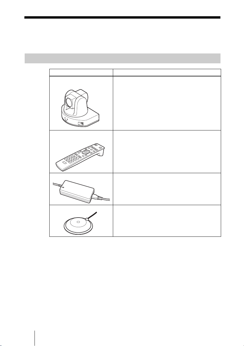
Basic System Components
Unit Description
PCS-XC1 HD Visual
Communication System
Consists of a camera, a codec block for processing,
transmitting, and receiving video and audio signals,
an echo canceller, a network interface block, and a
system control block.
PCS-RFZ1
Remote Commander
W
F
1
F
2
F
3
T
Use this to control the unit after pairing it with the
unit.
/
F
4
VGP-AC19V45 AC adaptor Supplies power to the unit.
PCS-A1 Microphone Omni-directional microphone that picks up sound
relatively from all directions, allowing participants to
speak from any location. It is recommended to use in
a quiet situation.
10 System Components

Optional Equipment
Optional equipment especially designed for use with the unit
The following optional devices are used to enhance your videoconference.
Unit Description
PCSA-RXC1 HD Upgrade
Software
PCSA-SAG1 Mobile Access
Software
Install this to enable transmission and reception of
1920 × 1080 progressive video at a maximum of
60 frames per second.
Use this to connect the unit to a mobile terminal.
Chapter 1: Installation and Preparation
11System Components
System Configuration
The unit has various system configuration capabilities using the basic
components and optional equipment. This section describes the capabilities
and necessary equipment for some typical configuration examples.
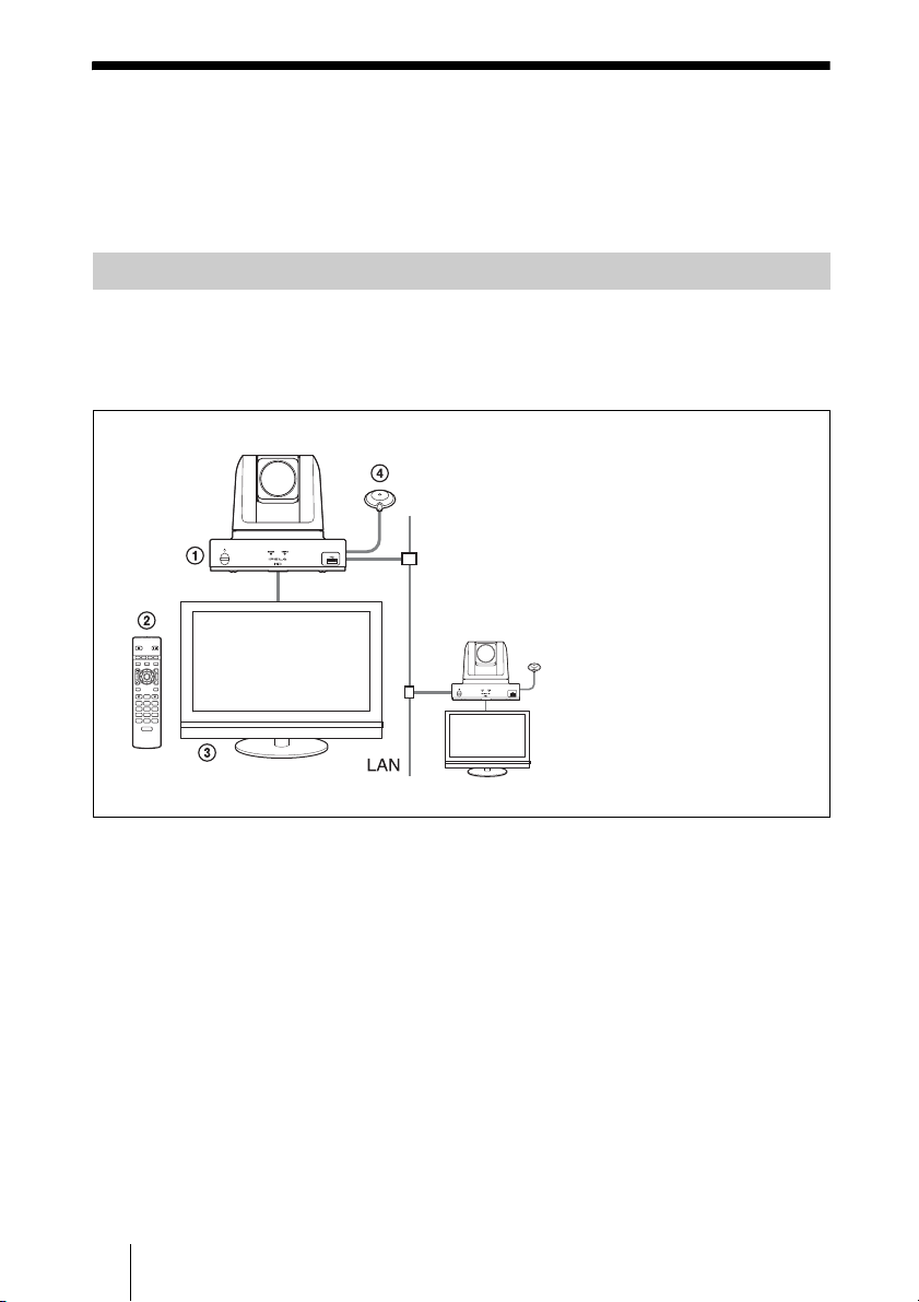
System Configuration via a LAN
This allows you to:
Have a point-to-point HD visual communication over LAN.
System configuration
/
T
W
1 Unit
2 Remote Commander (supplied)
3 TV monitor (not supplied)
4 Microphone (supplied)
12 System Configuration
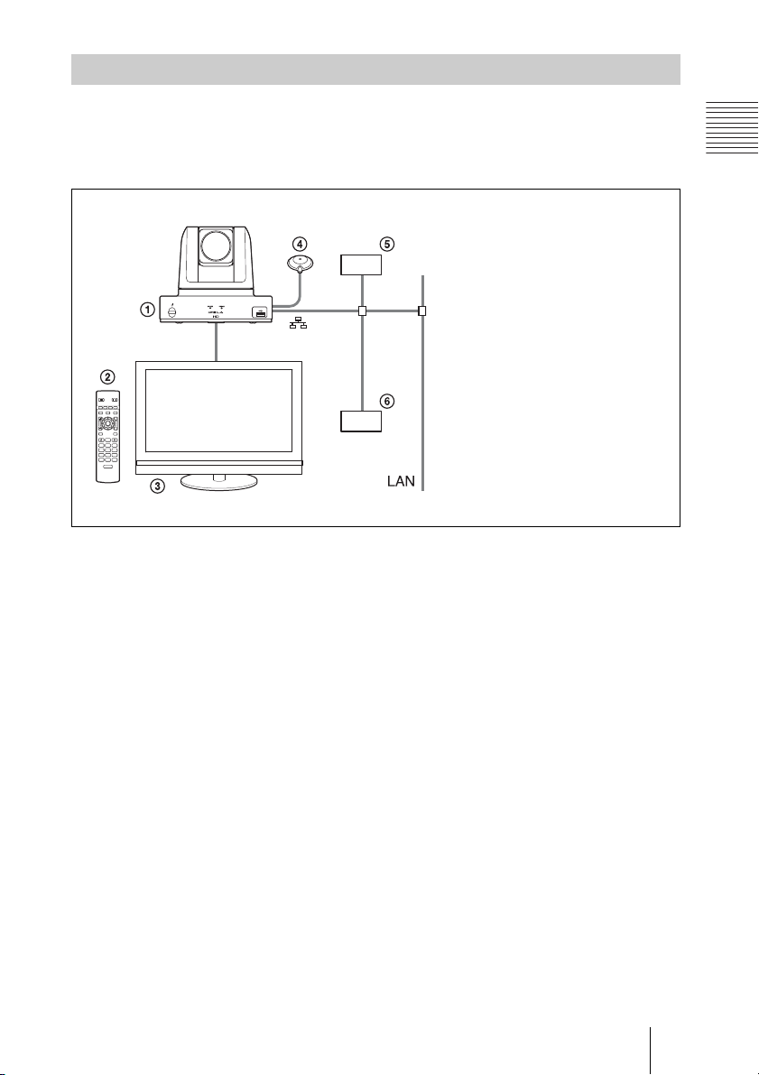
System Configuration via a SIP
This allows you to:
Have an HD visual communication with an IP telephone, etc. using SIP.
System configuration
/
T
W
Chapter 1: Installation and Preparation
1 Unit
2 Remote Commander (supplied)
3 TV monitor (not supplied)
4 Microphone (supplied)
5 SIP server
6 IP telephone, etc.
13System Configuration
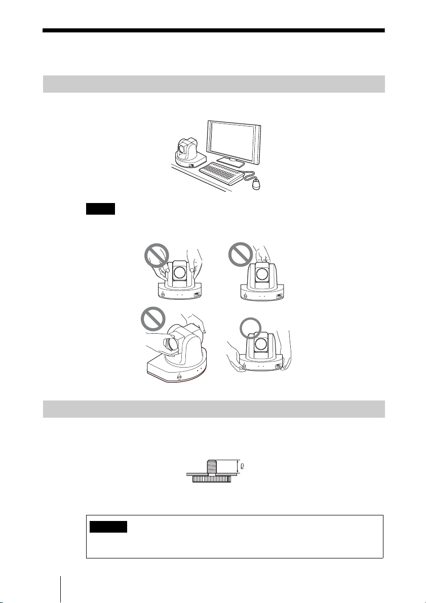
System Installation
Desktop Installation
Place the unit on a flat surface.
Notes
• Do not grasp the unit by the camera head when carrying the unit.
• Do not turn the camera head by hand. Doing so may result in a camera malfunction.
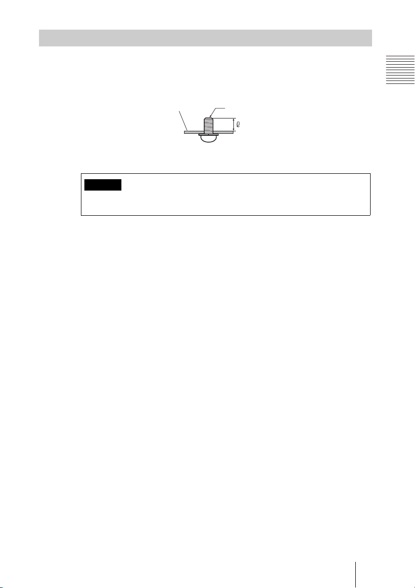
Using a Tripod
Use a screwdriver to tighten the tripod attachment screw while using the
following as a guide for the amount of protrusion (4) from the attachment surface.
Caution
Do not install the unit in high locations (shelves, ceilings, etc.) when using a tripod
screw.
14 System Installation
4 = 4.5 – 7 mm
4 = 0.18 – 0.27 inches
Using Fixing Screws
Secure the unit using the three M3 fixing screw holes located on the bottom of
the unit. Use M3 screws with the following specifications to attach the unit to
a fitting with a flat surface.
Fixing plate (not supplied)
Caution
Do not use parts that do not match the above specifications. Doing so may result in
damage to internal parts.
Chapter 1: Installation and Preparation
M3 screw
4 = 3 – 6 mm
4 = 1/8 – 1/4 inches
15System Installation

System Connections
This section describes the typical system connections.
Notes
• Be sure to turn off all the equipment before making any connections.
• For safety, do not connect the 1000BASE-T connector to a network that applies
excess voltage via the 1000BASE-T connector.
• We recommend using Sony HDMI cables.
16 System Connections
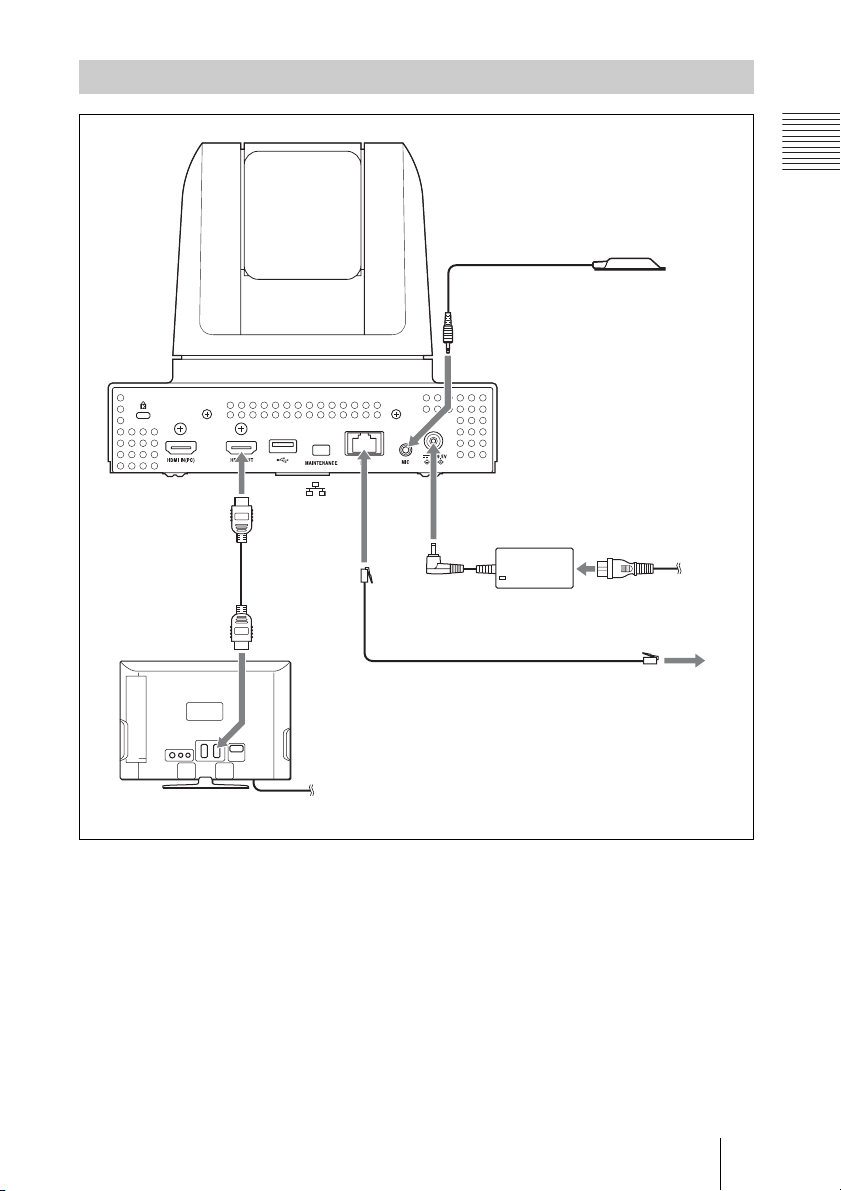
System Connection via a LAN
Chapter 1: Installation and Preparation
Microphone (supplied)
to MICto MIC
Unit
to HDMI
OUT
HDMI cable
(supplied)
to HDMI IN
to
TV monitor
(not supplied)
to a wall outlet
to DC19.5V
Power cord (supplied
only in Japan)
AC adaptor
(supplied)
UTP cable (category 6, straight, not supplied)
to a wall outlet
to LAN
17System Connections
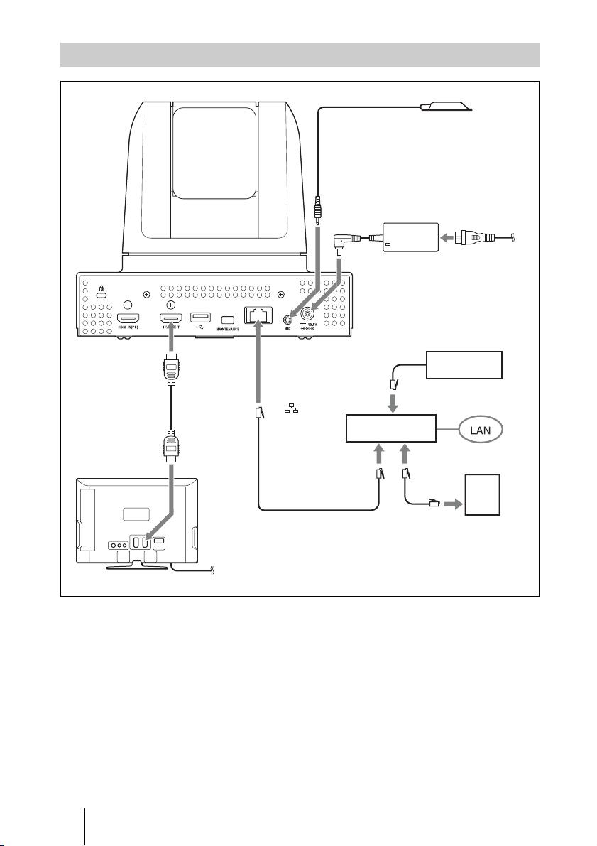
System Connection via a SIP
Microphone (supplied)
to HDMI
OUT
HDMI cable
(supplied)
to HDMI IN
Unit
to
UTP cable (category 6,
straight, not supplied)
TV monitor (not supplied)
to a wall outlet
to MIC
to
DC19.5V
to LAN
connector
AC adaptor
(supplied)
to LAN
connector
to LAN
connector
Power cord
(supplied only
in Japan)
to a wall outlet
SIP server
IP telephone,
etc.
18 System Connections
Preparing the System
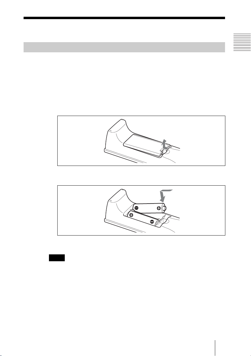
Inserting Batteries into the Remote Commander
CAUTION
Danger of explosion if battery is incorrectly replaced.
Replace only with the same or equivalent type recommended by the manufacturer.
When you dispose of the battery, you must obey the law in the relative area or country.
Most of the operations with the unit can be controlled with the supplied
Remote Commander.
1 Remove the battery compartment cover.
2 Insert two size AA (R6) batteries with correct polarities into the battery
compartment.
Chapter 1: Installation and Preparation
3 Replace the cover.
Note
Be sure to insert the batteries E side first. Inserting them forcibly e side first may
damage the insulated film covering the batteries and cause a short circuit.
Battery life
When the batteries are exhausted, the LED indicator does not light if you press
any button and the Remote Commander does not function properly. Replace
both batteries with new ones.
Notes on batteries
To avoid damage from possible battery leakage or corrosion, observe the
following:
19Preparing the System
• Make sure to insert the batteries with the polarities in the correct direction.
• Do not mix old and new batteries, or different types of batteries.
• Do not attempt to charge the batteries.
• If you do not intend to use the Remote Commander for a long period of time,
remove the batteries.
• If battery leakage occurs, clean the battery compartment and replace all the
batteries with new ones.
Installing batteries
Two size AA (R6) batteries are required to operate the supplied Remote
Commander.
To avoid risk of explosion, use size AA (R6) manganese or alkaline batteries.
Pairing the Remote Commander with the Unit
The supplied Remote Commander controls the unit using the radio frequency
of 2.4 GHz. The Remote Commander and the unit are paired to prevent
interference from other Remote Commanders and systems.
Pairing between the Remote Commander and the unit is programmed at the
factory.
Note
When performing a pairing procedure, be sure to turn off other HD Visual
Communication Systems located nearby that are not targets for pairing. If multiple
devices are turned on, the Remote Commander might pair with a device other than the
target one.
You can use the following procedure if you need to perform pairing with the
unit again.
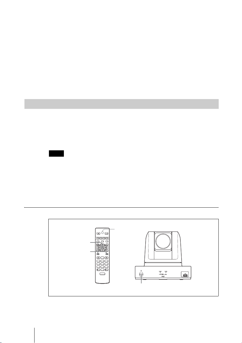
To pair the Remote Commander with the unit
VIDEO INPUT CAMERA
ENTER
BACK
SPACE
DISCONNECT
ABC DEF
0
ON/OFF
MIC
TOOLS
LED indicator
/
/
T
W
WXYZ
PRESENTATION
F1 F2 F3 F4
LAYOUT
VOLUME ZOOM
3
RETURN
2
CONNECT
123
GHI JKL MNO
456
PQRS TUV
789
TONE DOT
1 Press the 1 (power) switch on the unit to turn it on.
The POWER indicator lights when the unit turns on.
20 Preparing the System
1

2 Within 5 minutes after the power is on, locate the Remote Commander
closer to the unit, and press the RETURN and TOOLS buttons at the same
time.
The LED indicator flashes rapidly.
3 Press the ENTER button on the Remote Commander.
If the LED indicator flashes slowly 2 times
succeeded.
When pairing has failed
After about 30 seconds, the LED indicator on the Remote Commander flashes
slowly 5 times and then begins flashing rapidly. In this case, press the ENTER
button on the Remote Commander again.
To cancel pairing
When the LED indicator on the Remote Commander is flashing rapidly, press
1 (power) switch on the unit.
the
Notes
• When the LED indicator does not flash even if you press any button on the Remote
Commander, the batteries might be exhausted. Replace both batteries with new ones.
• Once pairing is established between the units, it will not be erased even if the batteries
are replaced.
• The operating range for the Remote Commander is 10 m. Depending on conditions,
this range may be larger.
, pairing between the units has
Chapter 1: Installation and Preparation
21Preparing the System
Turning the Unit On/Off
This section describes how to turn on or off the unit.
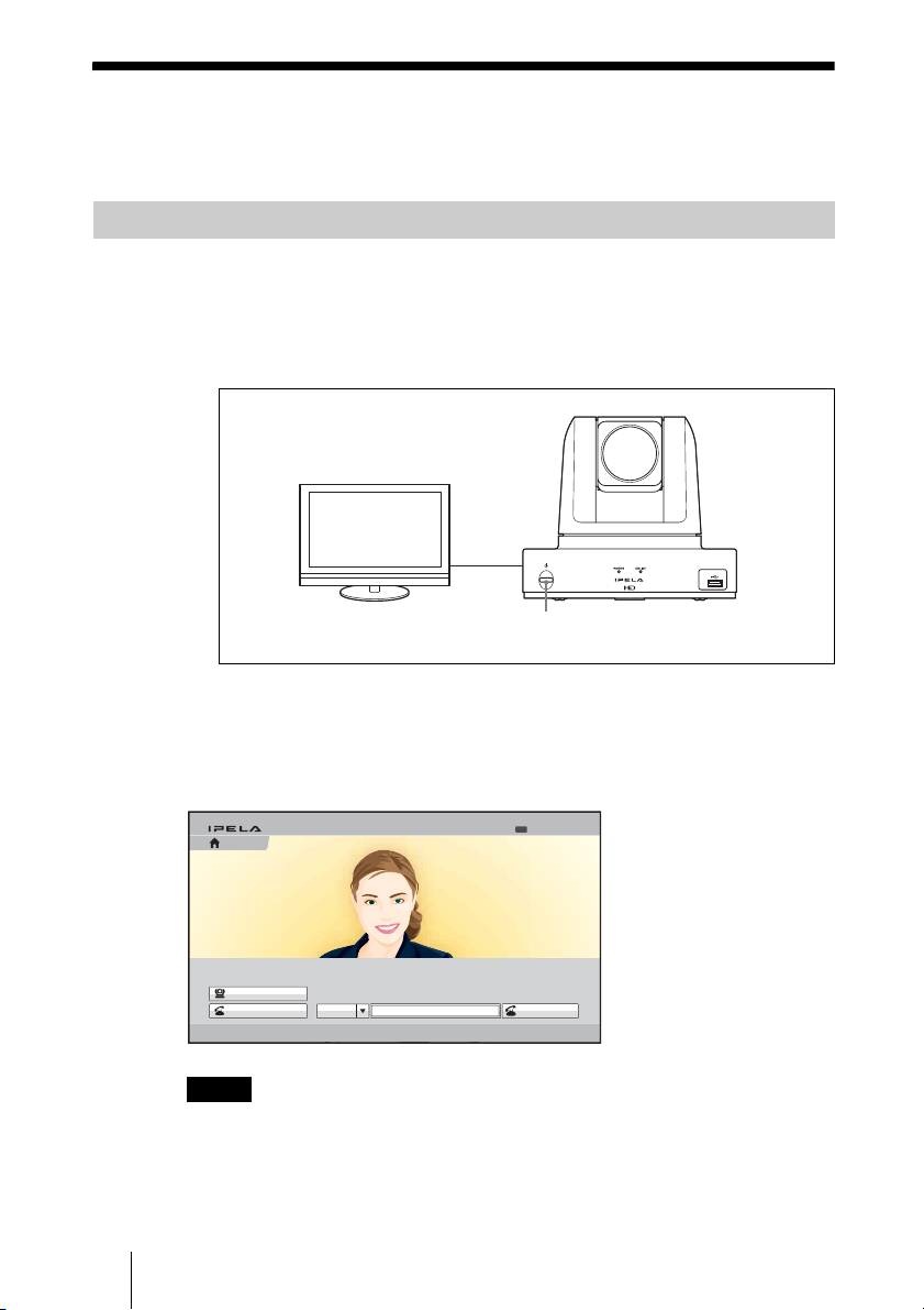
Turning On
1 Turn on the TV monitor.
2 Turn on the power of any other equipment to be used for this connection.
3 Press the 1 (power) switch on the unit to turn it on.
The POWER indicator lights when the unit turns on.
The Home menu will appear on the monitor screen and the picture shot by
the local camera will also appear in the Home menu.
1 (power) switch
Home menu
Camera
Connect
AAA
Home
Notes
• After the power is turned on, the camera moves automatically for trial operation. Be
careful not to catch your finger.
• If you use force to prevent the camera from moving, the camera may stop moving and
the picture may not be displayed. In this case, turn off the unit, and turn it on again.
22 Turning the Unit On/Off
Ready
5/11/2008 13:00IP:XXX.XXX.XXX.XXX
IP
Dial

• When you turn on the power of the unit for the first time after installation, the setup
wizard will appear after the self-diagnosis is completed. Set up your system following
the wizard.
For setups using the wizard, see “Setting Up the System Immediately after
the Installation – Initial Setup Wizard” on page 26.
• You can check the version of the unit, optional dedicated equipment connected, and
the application software installed using the Machine Status menu.
For details on the Machine Status menu, see page 64.
Standby Mode Function
To save power, the unit will enter standby mode if you do not operate it for a
specified period of time. When the unit is in standby mode, the POWER
indicator blinks slowly (about once every 5 sec.).
You can turn on the unit with any button on the Remote Commander if the unit
is in standby mode.
Once the unit receives a call, the standby mode is automatically released.
Setting the Unit to Standby Mode
1 Display the Home menu on the monitor screen, then press the @/1 button
on the Remote Commander.
The message “Power off?” appears on the monitor screen.
Chapter 1: Installation and Preparation
2 Press the V, v, B or b button on the Remote Commander to select OK, then
press the ENTER button.
Alternatively, you can press the
The unit enters standby mode, and the POWER indicator blinks slowly
(about once every 5 sec.).
To cancel setting the unit to standby
Select “Cancel” with the V, v, B or b button on the Remote Commander, then
press the ENTER button in step 2 above.
To release the standby mode
Press any button on the Remote Commander.
To specify the standby time
Specify the time that you want the unit to remain on before entering into
standby mode (1 to 99 minutes) by setting “Standby Time” of the Device Setup
page of the General setup menu. If you do not want the unit to enter the standby
mode, set “Standby Mode” to “Off”.
For the settings, see “Standby Time” and “Standby Mode” in the General
setup menu on page 54.
@/1 button on the Remote Commander.
23Turning the Unit On/Off

Turning Off
1 Press the 1 (power) switch on the unit.
The message “Power off?” appears on the monitor screen.
2 Press the V, v, B or b button on the Remote Commander to select “Power
off”, and press the ENTER button.
You can power off the unit by pressing the
Remote Commander.
The unit turns off.
3 Turn off the power of other equipment used for the communication.
Notes
• Turn off the power switch on the unit when the unit will not be used for an extended
period. While the power switch is off, you cannot receive a call from a remote party.
• Be sure to unplug the power cord after the power of the unit is turned off completely.
• If the unit is left unplugged for about one week or longer, the clock setting of the
system may reset. In such cases, set the date and time again in the Clock Set page of
the General setup menu.
Adjusting the Volume on the TV Monitor
The procedure for volume adjustment during system setup differs from the
procedure during communication.
Adjust the volume on the TV monitor during system setup, and adjust the
system volume during communication.
@/1 (power) button on the
Volume adjustment during setup
Adjust the system volume before adjusting the volume on the TV monitor.
1 Press the VOLUME +/– buttons on the Remote Commander to set the
volume level on the adjustment bar displayed on the screen to the middle
position.
2 Adjust the volume on the TV monitor so that you can properly hear a
remote party’s speaking.
24 Turning the Unit On/Off
11

Note
Do not activate the TV’s surround sound feature as it may cause the echo canceller of
the unit to not function properly and make strange sounds.
Volume adjustment during communication
Press the VOLUME +/– buttons on the Remote Commander to adjust the
system volume during communication.
Chapter 1: Installation and Preparation
25Turning the Unit On/Off
Setting Up the System Immediately
after the Installation – Initial Setup
Wizard
When you turn on the unit for the first time after installation and the selfdiagnosis is completed, the setup wizard appears on the monitor screen.
Register your local system data with the setup wizard using the Remote
Commander.
You can change the settings made with the setup wizard later using the setup
menus.
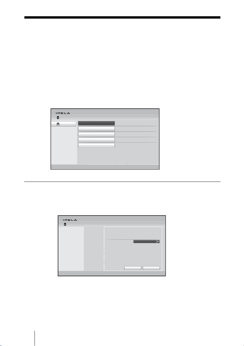
Wizard
Home
Back to Tools
Select Language
Set Region and Clock
Select Line I/F
Set up LAN
Set up SIP
To select the on-screen language
1 Use the V, v, B or b button on the Remote Commander to select “Select
Language” in the setup wizard, then press the ENTER button.
Wizard Select Language
Select Language
English
2007.11.29 14:21
IP
XXX.XXX.XXX.XXX
Select the on-screen language.
English
5/11/2008 13:00IP:192.168.0.11
5/11/2008 13:00IP:192.168.0.11
CancelSave
2 Use the V, v, B or b button on the Remote Commander to select the
language to be used for the on-screen menus and messages.
Select from among English, French, German, Japanese, Spanish, Italian,
Simplified Chinese, Portuguese, Traditional Chinese, Korean, Dutch,
26 Setting Up the System Immediately after the Installation – Initial Setup Wizard
Danish, Swedish, Finnish, Polish, Russian, Arabic, Thai, Turkish,
Norwegian, Welsh, Czech and Hungarian.
3 Use the V, v, B or b button on the Remote Commander to select “Save”,
then press the ENTER button.
The setup wizard is restored.
To set the region and clock
1 Use the V, v, B or b button on the Remote Commander to select “Set
Region and Clock” in the setup wizard, then press the ENTER button.
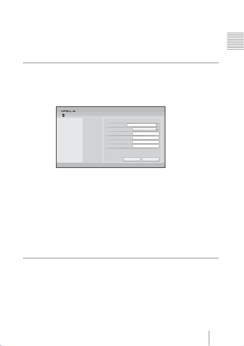
2 Set the region and clock items.
Wizard
Set Region and Clock
Set Region and Clock
Select the region: Select the country or region where the unit is used.
Select the display pattern: Select the display pattern of year, month and
day.
Enter the year, Enter the month, Enter the day, Enter the time: Enter
the date and time using the number buttons on the Remote
Commander.
Select the region
Select the display pattern
Enter the year
Enter the month
Enter the day
Enter the time
Chapter 1: Installation and Preparation
Year/Month/Day
CancelSave
For the procedure to enter the numbers using the Remote Commander, see
“Entering Characters Using the Remote Commander” on page 38.
3 Use the V, v, B or b button on the Remote Commander to select “Save”,
then press the ENTER button.
The setup wizard is restored.
To select the line interface
1 Use the V, v, B or b button on the Remote Commander to select “Select
Line I/F” in the setup wizard, then press the ENTER button.
27Setting Up the System Immediately after the Installation – Initial Setup Wizard

2 Select the line interface to be used.
Select Line I/F
Wizard
Which is your Line I/F?: Select from IP and SIP.
Which is your primary Line I/F?: If you selected more than one interface
in “Which is your Line I/F?”, select the interface you use the most here.
3 Use the V, v, B or b button on the Remote Commander to select “Save”,
then press the ENTER button.
The setup wizard appears.
To set up a LAN connection
Select “Set up LAN” in the setup wizard, then set up a LAN connection.
To set up a SIP
Select “Set up SIP” in the setup wizard, then set up a SIP connection.
Which is your Line I/F? (Multiple selection available)
Select Line I/F
IP
Which is your primary Line I/F?
IP
SIP
SIP
CancelSave
28 Setting Up the System Immediately after the Installation – Initial Setup Wizard
Using the Menus
1
q
23 4 5 6
q
q
q
The unit uses the on-screen menus to make various adjustments and settings.
This section explains how to adjust or set the items in the menus and gives a
brief introduction to the menus.
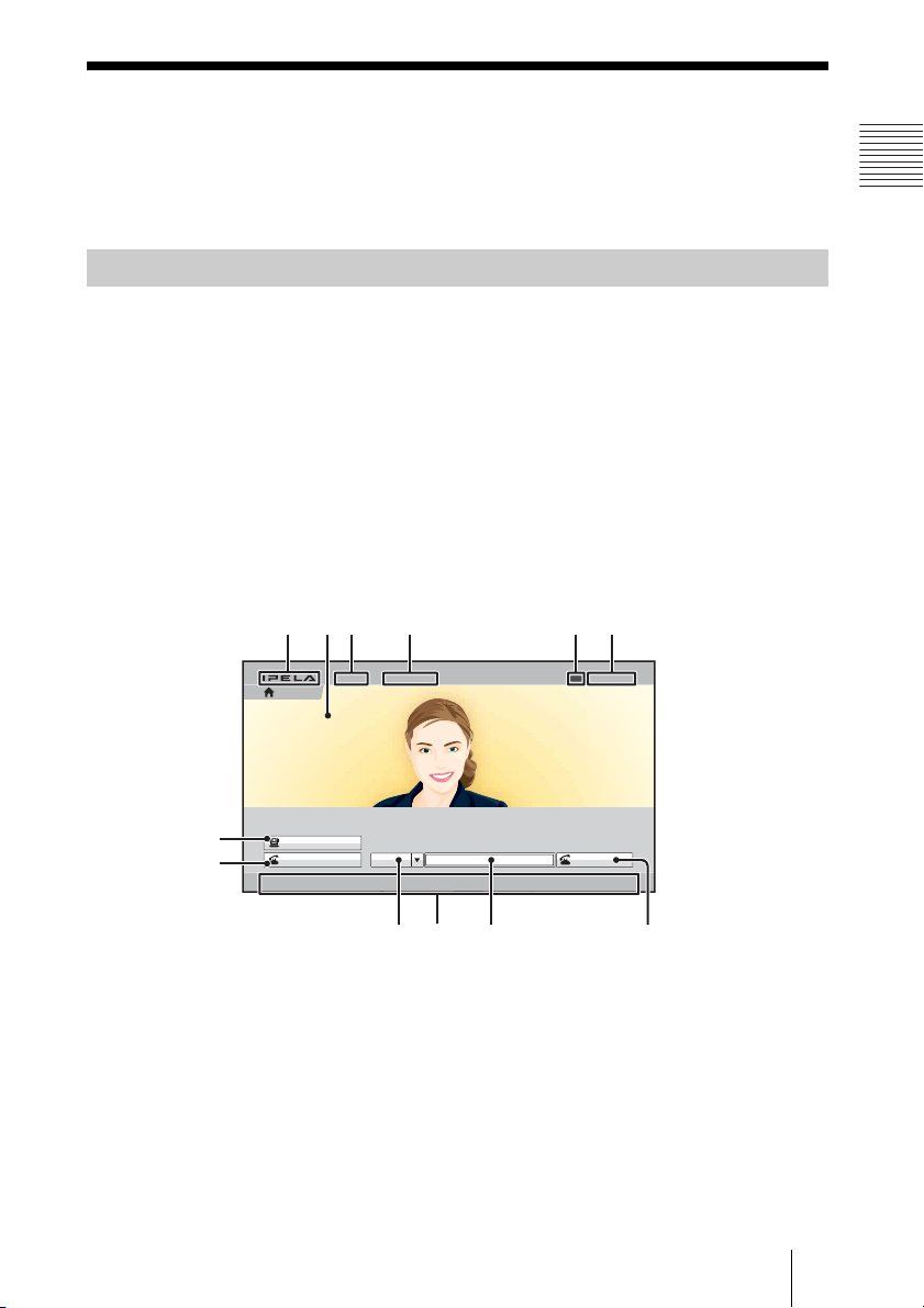
Identifying the Home Menu
The Home menu is displayed on the monitor screen when the unit is
turned on and has not been connected to a remote party. The Home menu
displays the image shot by the local camera, local system name, current date
and time and buttons to open the menus.
You can select the items shown in the Home menu using the Home Menu1 to
Home Menu3 pages in the Home Menu setup menu.
The descriptions of the items displayed in the Home menu are given below
using the default menu and the menu with all items shown, as the examples.
For details on the Home Menu setup menu, see page 56.
Home menu (default)
Chapter 1: Installation and Preparation
Home
7
qa
Camera
Connect
AAA
IP
IP
d
f
g
Ready
5/11/2008 13:00IP:XXX.XXX.XXX.XXXIP:XXX.XXX.XXX.XXX
Dial
Dial
h
29Using the Menus
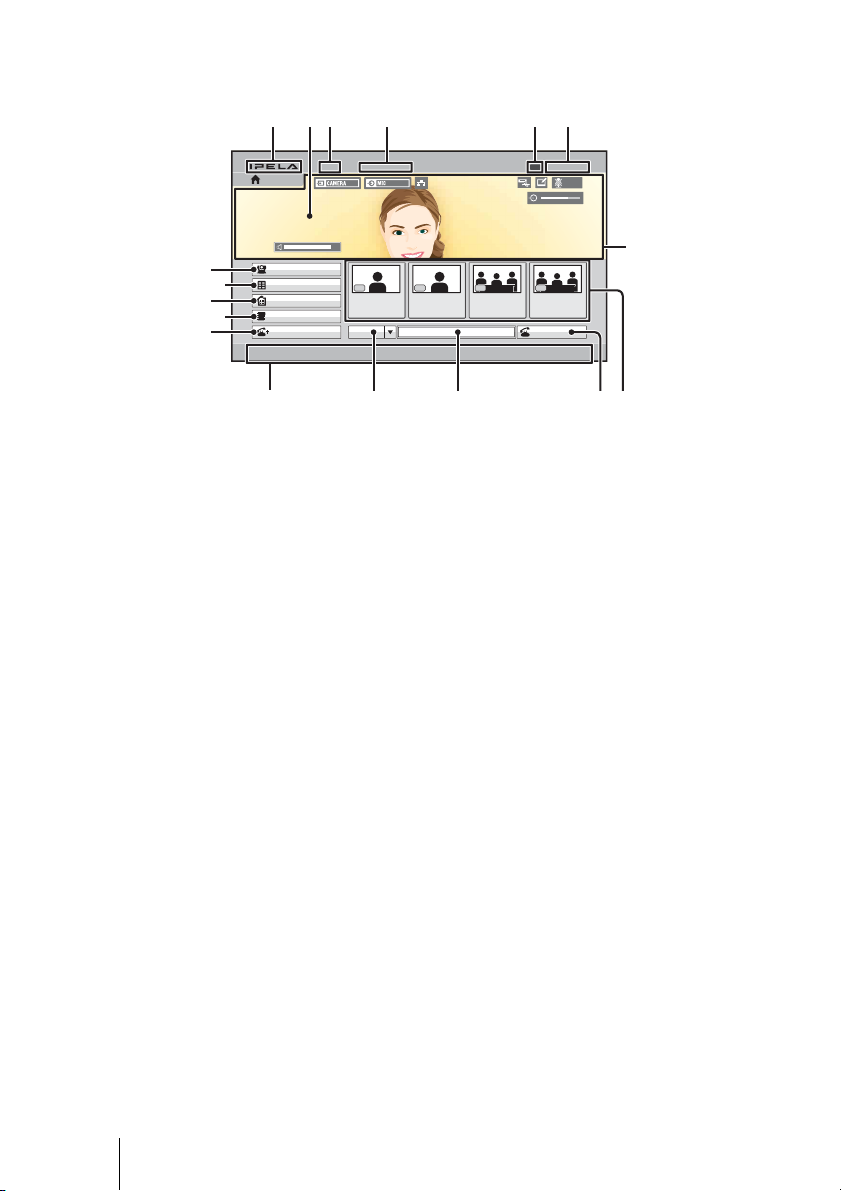
Home menu (with all items shown)
1
356
2 4
Home
AAA
Ready
5/11/2008 13:00IP:XXX.XXX.XXX.XXX
NEAR
qk
7
9
qs
8
0
Camera
Tools
History
Phone Book
Detailed Dial
F1 F3 F4
Room 101
IP
F2
Office EOffice ARoom 201
Dial
qd qf qg qh qj
1 IPELA logo
B Background screen
Image shot by the camera is displayed.
C Local terminal name
The local terminal name set in the menu is displayed.
D IP address of the local system
The IP address of the local terminal is shown.
By changing the “Number Display” setting (page 56) on the Home Menu1
page of the Home Menu setup menu, you can display the gatekeeper’s user
name and user number, NAT address, etc. instead of the IP address.
E Local system status
The status on the local terminal is shown.
F Date and time
The current date and clock are displayed.
G Camera button
The Camera menu opens when you select the button and press the ENTER
button on the Remote Commander.
The Camera menu is used to adjust the camera angle or brightness, or to
preset the camera adjustments and to move the camera to the preset
position.
30 Using the Menus
 Loading...