

Sony IPELA PCS-TL33, IPELA PCS-TL30 User Manual

Video
Communication
System
3-992-426-32 (1)
IPELA VC Link Guide
PCS-TL33/TL30
© 2006 Sony Corporation
Connecting to an external server with the IPELA VC Link
function enables you to use the IPELA VC Link service.
This guide describes the procedures and settings needed to
use the IPELA VC Link service.
Preparing for a
Videoconference With the
IPELA VC Link service is only available in Japan.
For more about the IPELA VC Link service, consult your
Sony dealer.
IPELA VC Link Function
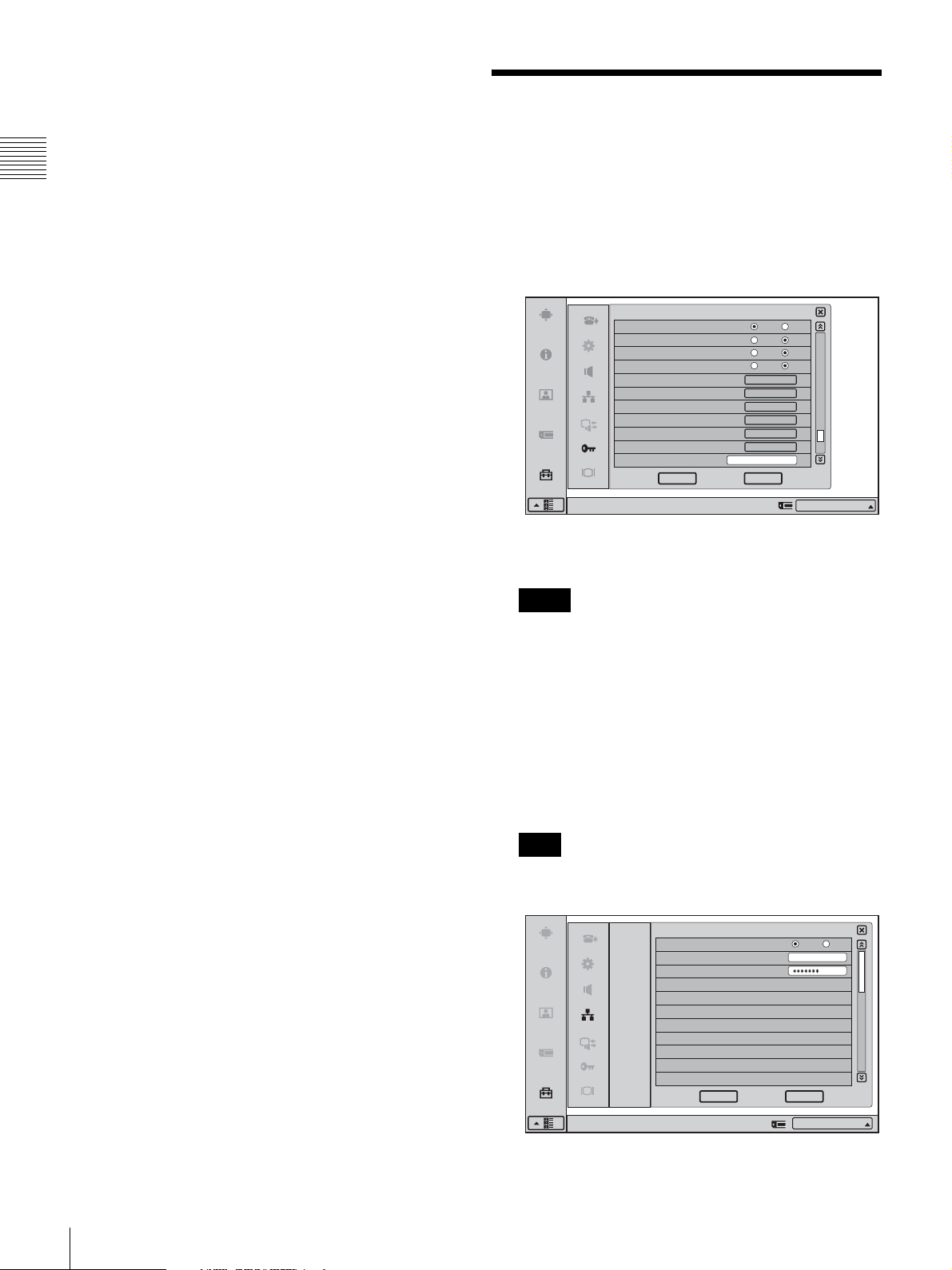
1
Enter an extension command with “Function
Extension Command” on Page 10 of the
Administrator Setup menu, and click [OK].
Administrator Setup
Capture remote image
Ringer with headphones
Display DTMF button
Auto Restore
Restore factory defaults
Save Application Software
Update software
Memory Stick Format
Save Setup
Load Setup
Function Extension Command
Right-click the mouse to display a help message.
The Network Setup menu switches to the “IPELA VC
Link” screen.
Notes
• For details on obtaining the “Function Extension
Command,” consult your Sony dealer.
• If the “SIP Server Mode” setting is set to “On” on
Page 1 of SIP on the Network Setup menu, an error
message appears, and IPELA VC Link does not
activate. Set “SIP Server Mode” to “Off” before
entering the “Function Extension Command” again.
On Off
On Off
On Off
On Off
Start
Save
Start
Start
Save
Load
CancelOK
10/11
IP:012.345.678.912
2
Preparing for a Videoconference With the IPELA VC Link Function
2
Set “Use IPELA VC Link” to “On,” and enter an
“IPELA VC Link Number” and “Password.”
Note
For details on acquiring an IPELA VC Link number
and password, consult your Sony dealer.
IPELA VC Link
LAN
IPELA VC Link
SIP
Right-click to display the help file.
Enable IPELA VC Link
IPELA VC Link Number
Passwo rd
On Off
12345678
CancelOK
IP:
012.345.678.912
1/3
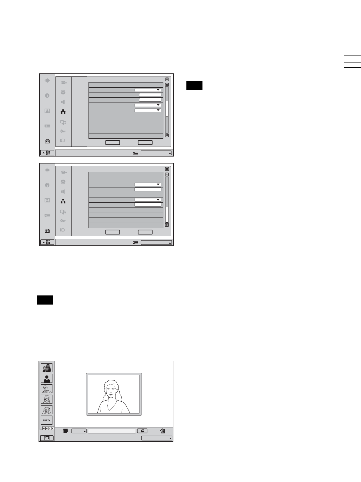
When “Enable IPELA VC Link” is set to “On,” the
“NAT Mode” item on Page 2 of the IPELA VC Link
menu automatically switches to “Auto (UPnP),” and
“Line I/F” and “Number Display” switch to “IPELA
VC Link.” In addition, the “LAN Bandwidth” item on
Page 3 automatically switches to “512 kbps.”
CancelOK
IP:
012.345.678.912
2/3
IPELA VC Link
LAN
IPELA VC Link
SIP
Right-click to display the help file.
IPELA VC Link Setup
NAT Mode
WAN IP Address
Port Number
Line I/F
Number Display
Auto (UPnP)
0.0.0.0
5060
IPELA VC Link
IPELA VC Link :
To confirm activation of the IPELA VC Link
function
See Page 4 of the Status & Info menu.
When the IPELA VC Link function is activated, the
IPELA VC Link setting and status appear on Page 4 of the
Status & Info menu.
Note
If no communications have been held since the power was
turned on, the IPELA VC Link setting and status appear on
Page 2.
IPELA VC Link
LAN
IPELA VC Link Setup
3
Click [OK].
IPELA VC Link
Right-click to display the help file.
Dial
SIP
LAN Bandwidth
Input LAN Bandwidth
Answer
LAN Bandwidth
Input LAN Bandwidth
512kbps
512
512kbps
512
CancelOK
IP:
012.345.678.912
The message “The NAT settings, line interface, and
LAN Bandwidth will be changed. Disabling the Web
Access setting is recommended.” appears.
Note
The Web Access setting can be changed on the
Administrator Setup menu.
4
Click [OK] in the message dialog box.
3/3
The first time the settings are configured the system
resets and the launcher menu appears.
IPELA VC Link
Point to and click on the icon with the mouse. IPELA VC Link :
12345678
Preparing for a Videoconference With the IPELA VC Link Function
3
 Loading...